ML11 SERIES SCISSOR LIFTS - Forward Lift | car lift, … SAFETY INSTRUCTIONS • Always keep area...
28
© April 2016 by Vehicle Service Group. All rights reserved. CO9757 OM50034 Rev. B 4/18/2016 ML11 SERIES SCISSOR LIFTS OPERATION & MAINTENANCE MANUAL IMPORTANT SAFETY INSTRUCTIONS ENCLOSED. READ ALL INSTRUCTIONS AND SAVE THESE INSTRUCTIONS WITH THE LIFT
Transcript of ML11 SERIES SCISSOR LIFTS - Forward Lift | car lift, … SAFETY INSTRUCTIONS • Always keep area...

© April 2016 by Vehicle Service Group. All rights reserved. CO9757 OM50034 Rev. B 4/18/2016
ML11 SERIESSCISSOR LIFTS
OPERATION & MAINTENANCE MANUAL
IMPORTANT SAFETY INSTRUCTIONS ENCLOSED. READ ALL INSTRUCTIONS AND SAVE THESE
INSTRUCTIONS WITH THE LIFT

2
The Owner/Employer:
• The Owner/Employer shall ensure that lift operators are qualified and that they are trained in the safe use and operation of the lift us-ing the manufacturer’s operating instructions; ALI/SM 93-1, ALI Lifting it Right safety manual; ALI/ST-90 ALI Safety Tips card; ANSI/ALI ALOIM-2008, American National Standard for Automotive Lifts-Safety Requirements for Operation, Inspection and Maintenance; ALI/WL Series, ALI Uniform Warning Label Decals/Placards; and in the case of frame engaging lifts, ALI/LP-GUIDE, Vehicle Lifting Points/Quick Reference Guide for Frame Engaging Lifts.
• The Owner/Employer shall establish procedures to periodically inspect the lift in accordance with the lift manufacturer’s instructions or ANSI/ALI ALOIM-2008, American National Standard for Automotive Lifts-Safety Requirements for Operation, Inspection and Mainte-nance; and The Employer Shall ensure that lift inspectors are qualified and that they are adequately trained in the inspection of the lift.
• The Owner/Employer shall establish procedures to periodically maintain the lift in accordance with the lift manufacturer’s instruc-tions or ANSI/ALI ALOIM-2008, American National Standard for Automotive Lifts-Safety Requirements for Operation, Inspection and Maintenance; and The Employer Shall ensure that lift maintenance personnel are qualified and that they are adequately trained in the maintenance of the lift.
• The Owner/Employer shall maintain the periodic inspection and maintenance records recommended by the manufacturer or ANSI/ALI ALOIM-2008, American National Standard for Automotive Lifts-Safety Requirements for Operation, Inspection and Maintenance.
• The Owner/Employer shall display the lift manufacturer’s operating instructions; ALI/SM 93-1, ALI Lifting it Right safety manual; ALI/ST-90 ALI Safety Tips card; ANSI/ALI ALOIM-2008, American National Standard for Automotive Lifts-Safety Requirements for Operation, Inspection and Maintenance; and in the case of frame engaging lifts, ALI/LP-GUIDE, Vehicle Lifting Points/Quick Reference Guide for Frame Engaging Lifts; in a conspicuous location in the lift area convenient to the operator.
• The Owner/Employer shall provide necessary lockout/tagout means for energy sources per ANSI Z244.1-1982 (R1993), Safety Re-quirements for the Lockout/Tagout of Energy Sources, before beginning any lift repairs.
• The Owner/Employer shall not modify the lift in any manner without the prior written consent of the manufacturer.
SAFETY INSTRUCTIONS
• Daily inspect your lift. Never operate if it malfunctions or if it has been broken or damaged parts. Use only qualified lift service personnel and genuine OEM parts to make repairs.
• Thoroughly train all employees in the use and care of lift and wheels free device, using manufacturer’s instructions and “Lifting It Right” and “Safety Instructions” supplied with the lift.
• DO NOT permit employees or customers on lift when it is either being raised or lowered.
• Never allow unauthorized or untrained persons to operate lift or wheels free device.
• Prohibit customers or non-authorized persons from being in shop area while lift is in use.
• DO NOT stand in front or behind lift while vehicle is being driven onto or backed off the lift.
• Load vehicle on lift carefully, align vehicle with runways before driving on.
• DO NOT allow rear tires or portion of vehicle to interfere with ramp/chocks.
• Never allow front wheels to strike the front wheel stops.
• Never raise or lower the lift while the vehicle is supported by the wheels free device. Only raise or lower the lift when all 4 tires of the vehicle are supported by the runway.
• Always stand clear of lift when raising or lowering and observe “Pinch Points” Warning.
• Never overload lift: capacity of lift is 11,000 lbs. (5,500 lbs. per axle.) CAPACITY SHOULD NOT BE EXCEEDED.
• Always engage parking brake and use the rear wheel chocks to keep the vehicle from rolling freely on the runways.
• Always lower lift on locks before working on vehicle.
If you are working under vehicle, lift should be raised high enough for locking latches to engage.
CAUTION

3
SAFETY INSTRUCTIONS• Always keep area around lift clean of tools, debris, grease, and oil.
• Always keep runway clean.
• Replace all caution, warning, or safety related decals on the lift when unable to read or missing.
• For Wheels Free Device Safety Instructions see Wheels Free Device Installation, Operation and Maintenance Instructions in the wheels free device box.
• DO NOT perform any maintenance on the power unit, control valves, air or fluid lines, hydraulic cylinders, or check fluid level until lift has been fully lowered and all pressure has been re-leased from system. Follow OSHA Lockout/Tagout procedures as they apply, reference ANSI Z244.1.
• DO NOT block open or override self-closing lift controls, they are designed to return to the off or neutralposition when released.
• Clean area if vehicle is in danger of falling.
• Remove tools, and other equipment from on or below lift before lowering lift.
Lowering lift legs onto an obstruction may
cause damage to lift.
CAUTION
Do not operatea damaged lift.
©
SAFETYINSTRUCTIONS
WARNING
Remain clear of liftwhen raising or lowering vehicle.
©
Proper maintenanceand inspection is necessary for safe operation. ©
SAFETYINSTRUCTIONS
WARNING
Keep clear of pinch points when lift is moving.
©
WARNING
Clear area if vehicle is in danger of falling.
©
Keep feet clear of lift while lowering.
©
WARNING
Read operating
before using lift.©
SAFETYINSTRUCTIONS
and safety manuals
WARNING
Chock wheel to prevent vehicle movement.
©
CAUTION
Lift to be used by trained operatorONLY.
©
? ??
WARNING
Do not overrideself-closinglift controls.
©
CAUTION
Authorized personnel only in lift area.
©
4
Purpose
This procedure establishes the minimum requirements for the lockout of energy that could cause injury to personnel by the operation of lifts in need of repair or being serviced. All employees shall comply with this procedure.
Responsibility
The responsibility for assuring that this procedure is followed is binding upon all employees and service personnel from outside service companies (i.e., Authorized Rotary Installers, contactors, etc.). All employees shall be instructed in the safety significance of the lockout procedure by the facility owner/manager. Each new or transferred employee along with visiting outside service personnel shall be instructed by the owner/manager (or assigned designee) in the purpose and use of the lockout procedure.
Preparation
Employees authorized to perform lockout shall ensure that the appropriate energy isolating device (i.e., circuit breaker, fuse, disconnect, etc.) is for the lift being locked out. Other such devices for other equipment may be located in close proximity of the appropriate energy isolating device. If the identity of the device is in question, see the shop supervisor for resolution. Assure that proper authorization is received prior to performing the lockout procedure.
Sequence of Lockout Procedure
1) Notify all affected employees that a lockout is being performed and the reason for it.2) Unload the subject lift. Shut it down and assure the disconnect switch is “OFF” on the lift.3) The authorized lockout person operates the main energy isolation device removing power to the subject lift.
• If this is a lockable device, the authorized lockout person places the assigned padlock on the device to prevent its unintentional reactivation. An appropriate tag is applied stating the person’s name, at least 3” x 6” in size, an easily noticeably color, and states not to operate device or remove tag.
• If this device is a non-lockable circuit breaker or fuse, replace with a “dummy” device and tag it appropriately as mentioned above.
4) Attempt to operate lift to assure the lockout is working. Be sure to return any switches to the “OFF” position.5) The equipment is now locked out and ready for the required maintenance or service.
Restoring Equipment to Service
1) Assure the work on the lift is complete and the area is clear of tools, vehicles, and personnel.2) At this point, the authorized person can remove the lock (or dummy circuit breaker or fuse) & tag and activate
the energy isolating device so that the lift may again be placed into operation.
Rules for Using Lockout Procedure
Use the Lockout Procedure whenever the lift is being repaired or serviced, waiting for repair when current operation could cause possible injury to personnel, or for any other situation when unintentional operation could injure personnel. No attempt shall be made to operate the lift when the energy isolating device is locked out.
LIFT LOCKOUT/TAGOUT PROCEDURE
Lift is not intended for outdoor use and has an operating ambient temperature range of 41º-104ºF (5º-40ºC).
OPERATING CONDITIONS
5
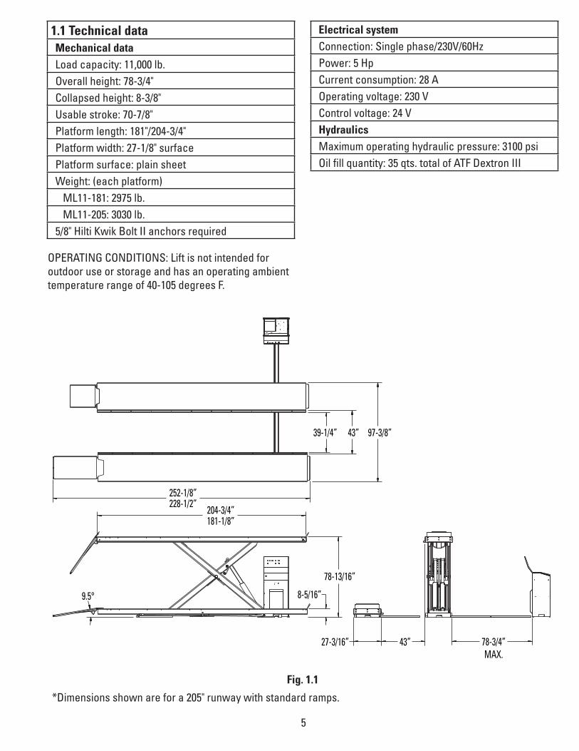
1.1 Technical data Mechanical dataLoad capacity: 11,000 lb.Overall height: 78-3/4"Collapsed height: 8-3/8"Usable stroke: 70-7/8"Platform length: 181"/204-3/4"Platform width: 27-1/8" surfacePlatform surface: plain sheetWeight: (each platform) ML11-181: 2975 lb. ML11-205: 3030 lb.5/8" Hilti Kwik Bolt II anchors required
39-1/4”
252-1/8”228-1/2”
204-3/4”181-1/8”
78-13/16”
8-5/16”
27-3/16” 43” 78-3/4”MAX.
9.5°
43” 97-3/8”
Electrical systemConnection: Single phase/230V/60HzPower: 5 Hp Current consumption: 28 AOperating voltage: 230 VControl voltage: 24 VHydraulicsMaximum operating hydraulic pressure: 3100 psiOil fill quantity: 35 qts. total of ATF Dextron III
Fig. 1.1
*Dimensions shown are for a 205" runway with standard ramps.
OPERATING CONDITIONS: Lift is not intended for outdoor use or storage and has an operating ambient temperature range of 40-105 degrees F.

6
1.2 Proper use The machine lifts vehicles continuously to any ergonomically favorable height. The permissible load capacity may not be exceeded (see load capacity plate, type plate or Chap. 1.1 "Technical data", page 5).
The machine may only be used as intended! Severe injuries or equipment damage can result from improper use! This is not the responsibility of the manufacturer of the machine, but of the operating company!
The machine is designed for the performance of work underneath the load-bearing equipment and the vehicle. It is not approved for supporting or transporting persons.
The following is especially prohibited:
• Transport of persons.
• Standing on the platform.
• Operating in areas at risk of explosion.
• Operating in areas requiring a protection type for the electrical equipment higher than IP 54.
• Automatic release of the mechanical locking latches is prohibited.
1.3 Warning and safety notices used Warning and safety notices contain information designed to point out the unavoidable residual risks involved in handling the machine. The hazards apply to the following:
• Persons
• Machine
• Equipment
• Environment
1.3.1 Structure of the warning notices The warning notices of this operating manual have an identical basic structure.
Icon Danger sign Signal word
Type and source of danger
Possible consequences of non-observance
• Avoidance: measures / prohibitions
1.3.2 Explanation of the warning levels Warning level Consequences of non-observance
Immediate danger of severe injuries or death
WARNING Severe injuries or death are possible
CAUTION Minor injuries are possible
Equipment damage
7
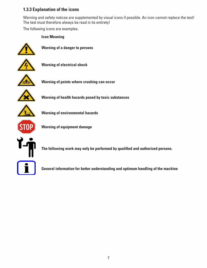
1.3.3 Explanation of the icons
Warning and safety notices are supplemented by visual icons if possible. An icon cannot replace the text! The text must therefore always be read in its entirety!
The following icons are examples.
Icon Meaning
Warning of a danger to persons
Warning of electrical shock
Warning of points where crushing can occur
Warning of health hazards posed by toxic substances
Warning of environmental hazards
Warning of equipment damage
The following work may only be performed by qualified and authorized persons.
General information for better understanding and optimum handling of the machine
8
1.4 Technical condition of the equipment
Safe operation places particular demands on the technical condition of the machine.
• Rebuilding, manipulation or making modifications to the machine is not permitted. This also applies to the use of replacement parts that are not supplied by us.
• Care and maintenance should be performed at the specified intervals.
• Regular inspections are to be carried out.
• Complete and proper functioning of the safety devices during operation must be ensured at all times.
• Connection and setting values must correspond to the specifications.
• Load specifications must be observed.
1.5 Obligations of the operating company The highest possible level of safety can only be achieved in operating practice if all measures required for it have been taken. It is the responsibility of the operating company to plan these measures and monitor their implementation.
The operating company must ensure the following in particular:
• The machine is only used as intended (Chap. 1.2 "Proper use", page 6).
• The machine is only operated in technically flawless and functional condition.
• The safety devices are regularly checked for proper functioning. The safety devices may not be disabled nor have their functions restricted.
• The maintenance and inspection intervals specified in this operating manual are observed (Chap. 5.1 "Main-tenance and inspections", page 20).
• All safety and warning notices attached to the machine are present and in legible condition. Notices on the machine that have become damaged or illegible are to be replaced immediately.
• Only qualified and authorized personnel may operate service and inspect the machine.
• These persons must be regularly instructed in all applicable aspects of work safety and environmental protection, as well as be familiar with and follow the operating manual and the safety instructions contained within it.
• The required personal protective equipment for operating, maintenance and inspection personnel must be made available and used.
• The operating manual should be complete and in legible condition and readily accessible where the machine is in use.
• Further risks must be determined in a risk assessment and the respective danger zone must be identified under consideration of the special work conditions where the machine is in use.
• All additional instructions and safety notices must be summarized in a company directive based on the risk assessment of the workstations on the machine.

9
1.6 General work safety
When the machine is used, dangers due to incorrect operation or misuse may pose a hazard to persons, equip-ment or the environment.
• The machine may only be operated, serviced and inspected by qualified and authorized personnel who have read the operating manual and perform their work accordingly.
• Only operate the machine in technically flawless and functional condition.
• If damage is detected, immediately switch off the machine, attach a sign informing others that switching back on is prohibited and then inform your supervisor.
• Maintain the cleanliness of the machine and its surroundings.
• Wear personal protective equipment.
1.7 Safety instructions in regard to specific energy systems
1.7.1 Electrical system
The machine is equipped with an electrical system that operates with high voltage.
• Prior to beginning work, inspect the electrical system for visible signs of damage. Immediately replace damaged components.
• Before performing maintenance work, switch off the current to the electrical system and prevent it from being accidentally switched back on.
• Always keep the control boxes closed.
• Lay lines so that they do not pose a stumbling hazard and so that damage due to falling objects, pinching or abrasion is avoided.
• Do not lay lines around moving components and ensure that the lines cannot catch on any moving com-ponents.
• Protect the electrical system from penetration by water or other liquids.
• Regularly inspect lines, especially after maintenance work, for secure fit.
1.7.2 Hydraulic system
Hydraulic oil, lubricants and other substances, such as solvents or cleansers, can lead to irritation of the skin, eyes or respiratory tract. These also pose a hazard to the environment.
• Observe the safety instructions of the manufacturer.
• Use personal protective equipment.
• Use a breathing protection mask if necessary.
• Avoid contact with the skin. Should contact with skin arise, wash thoroughly.
• In the event of contact with eyes, rinse and consult a physician.
• Ensure that no substances contaminate the ground or enter the sewer system.
• Dispose of hydraulic oil, lubricants and cleansers in accordance with environmental regulations.

10
1.7.3 Mechanical system
When using and working on the machine, mechanical hazards are present. These hazards are posed in the area of the mechanics underneath the platform.
• Do not reach into or enter the danger zone.
• Avoid standing in the danger zone.
• Remove any foreign objects from the danger zone.
Fig. 1.0 Mechanical danger zones
11
1.8 Safety devices on the machine
1.8.1 Deadman control The deadman control of the machine ensures that the function is only carried out as long as the operator holds the respective control pressed on the control device.
1.8.2 Independent hydraulic circuits Two hydraulic circuits independent of one another prevent the unintended lowering of the platform. In the event of a break in a hydraulic line in one of the hydraulic circuits, the other hydraulic circuit holds the plat-form.
1.8.4 Main switch The main switch turns the current supply to the machine on and off. Padlock the switch to prevent unauthor-ized personnel from using the lift.
1.8.5 Pressure limiting valve The pressure limiting valve prevents overloading of the hydraulic system. It is factory preset and may not be adjusted by the operating company. When overloaded, the platform can no longer be raised.
1.8.6 Line breakage protection in the cylinder connection The line-break safety device in the cylinder connection interrupts the flow if a break occurs in the hydraulic lines.
1.9 Safety and warning notices The machine is labeled with various notices. The notices should always be present and in legible condition.
11,000 lb.CAPACITYPROTATA
CAPACITE’TRAGFÄHIGLEIT
NOTE!Maximum load capacity.

12
1.10 Safety instructions for personnel
1.10.1 Personnel and qualifications All persons working with the machine must read the operating manual prior to beginning the work and confirm with their signature that they have understood what they have read and agree to observe it.
• Only persons of at least 18 years of age who have been instructed in the machine's operation, and have demonstrated their ability in this regard to the employer, may be delegated with operation of the machine.
• The assignment to the task of operating the machine must be given in writing.
• The respective authorizations of the person must be defined.
• Trainees must receive instruction. The instruction may only be performed by experienced persons autho-rized to do so and using this operating manual as a basis.
• Instructed persons confirm in writing the scope of instruction received and their successful completion of it.
1.11 Safety instructions for auxiliary materials and consumables
1.11.1 Hydraulic oils, lubricants and cleansers Hydraulic oil, lubricants and other substances, such as solvents or cleansers, can lead to irritation of the skin, eyes or respiratory tract. These also pose a hazard to the environment.
• Observe the safety instructions of the manufacturer.
• Use personal protective equipment.
• Use a breathing protection mask if necessary.
• Avoid contact with the skin. Should contact with skin arise, wash thoroughly.
• In the event of contact with eyes, rinse and consult a physician.
• Ensure that no substances contaminate the ground or enter the sewer system.
• Dispose of hydraulic oil, lubricants and cleansers in accordance with environmental regulations.

13
• Starting up
2.1 Basic safety instructions
Prior to the initial commissioning, a safety inspection must be performed by a qualified and authorized person. This person must confirm and document the technically flawless functioning of the machine.
In Germany, inspection according to GUV-G 945 must be carried out. For this, use the inspection log book in the appendix of this operating manual.
The following is to be checked:
• correct installation
• proper functioning of safety devices
• operational readiness
2.2 Initial commissioning
Prior to initial commissioning
10 Inspect the machine for visible signs of damage. If damage is detected:
• Do not switch on the machine.
• Attach or erect a notice sign prohibiting switching on the machine.
• Notify your supervisor of the detected damage.
• Only use the machine if all damage has been repaired.
• Remove any foreign objects from the danger zone (Fig. 1.0, page10).
• Remove materials and objects from the work area if they are not required.
• Check and ensure that all safety devices are functioning flawlessly.
The preparations are completed.
Before starting the machine, check and ensure the following:
• Only authorized persons are in the work area of the machine.
• No one will be endangered by the starting up of the machine.
• Measures have been taken to prevent unintended changes in the position of the load.
• A clear view is available of the load, the machine and particularly the danger zone (Fig. 1.0, page 10).
• Avenues of escape are available in the event of danger.

14
2.2.2 Bleeding the hydraulic system
• After positioning the lift as specified and performing electric and hydraulic connections, the lift can be oper-ated by following the specific procedure.
• Move the master switch to the "1" position and press the lifting button. If the lift does not operate but the motor runs regularly, check the motor for proper direction of rotation and switch the phases on the power supply line if necessary. Press the button again until platforms are fully lifted.
• Hold the switch "up" for 2-3 seconds in the upper position.
• Open the bleed screws (1) on the slave cylinder as shown in Fig. 2.1 and close them again after bleeding air from the cylinders. Press the lifting button again, then open the bleed screws again (1) Fig. 2.1 to bleed air from the cylinders.
• After tightening the bleed screws, repeat the operation to make sure there is no air in the circuit.
• Lower the lift to the ground, and perform several cycles with the lift unloaded to check there are no oil leaks and platforms are properly leveled.
• Press the lowering button to lower the lift.
• Perform the lifting/lowering operations 4/5 times.
• After bleeding the system, lower the lift fully and fill the hydraulic system to the top line in the sight glass gauge.
• Bleed the system again after any hoses have changed.
Fig. 2.1
Check the following after the first startup:
10 All hydraulic hoses for any leaks.
Bleeder Screw

15
2.2.3 Checking the hydraulic hoses
For hydraulic hoses, a yearly inspection of operationally safe condition is prescribed. The inspection must be performed by a qualified and authorized specialist!
Hydraulic hoses conforming to DIN EN 853/2SN or DIN EN 856/4SP are built into the machine.
Checking the hydraulic hoses
Perform a visual check of the hydraulic hoses:
• Is any damage on the exterior, such as cracks, kinks, cuts, stripped points, areas of abrasion, brittleness, etc., detectable?
• Are there any deformations of the hose in either depressurized or pressurized condition?
• Are there any leaks between hose and fittings?
• Are the fittings loose on the hose?
• Replace hydraulic hoses if damage is detected, but after every 6 years at the latest.
The inspection is completed.

16
Operation
3.1 Basic safety instructions
WARNING
Scissors and castors
Crushing or amputation of limbs
• Do not reach or step into the danger zone (Fig. 1.0, page 10).
WARNING
Improper placement of the load
• Death or severe injuries from falling loads
• Observe the permissible load capacity of the machine (see load capacity plate, type plate or Chap. 1.1 "Tech-nical data", page 5).
• Only place loads of the permissible type on the machine.
• The load may not protrude beyond the platform.
• Prevent unintended changes in the position of the load.
Incorrect operation
Severe damage to the machine
• Avoid repeated, sudden jolts when lifting and lowering the platform.
Before beginning each work shift
10 Inspect the machine for visible signs of damage. If damage is detected:
• Do not switch on the machine.
• Attach or erect a notice sign prohibiting switching on the machine.
• Notify your supervisor of the detected damage.
• Only use the machine if all damage has been repaired.
• Remove any foreign objects from the danger zone (Fig. 1.0, page 10).
• Remove materials and objects from the work area if they are not required.
• Check and ensure that all safety devices are functioning flawlessly.
The preparations are completed.

17
Before operating the machine each time, check and ensure the following:
• Only authorized persons are in the work area of the machine.
• No one will be endangered by the starting up of the machine.
• Measures have been taken to prevent unintended changes in the position of the load.
• A clear view is available of the load, the machine and particularly the danger zone (Fig. 1.0, page 10).
• Avenues of escape are available in the event of danger.
3.2 Description of the controls
Fig. 3.2 Control device
1. Control: «Main switch»
Setting the switch to "1" switches on the power supply - control lamp (A) lights up.
Setting the switch to "0" switches off the power supply - control lamp (A) goes dark.
The «main switch» can be locked with a padlock. This secures the machine against unintentional operation.
2. Control: «Lift»
By pressing the «Lift» control, the platform raises.
The movement stops as soon as the control is no longer held pressed (deadman control).
3. Control: «Lower»
By pressing the «Lower» control, the platform lowers.
The movement stops as soon as the control is no longer held pressed (deadman control).
When the Euro Stop is reached, the lowering motion stops in order to prevent crushing and other hazards. If the lowering motion is to be resumed, press the «Lower» control again. The platform continues to lower and a warning signal sounds.
4. «Lower to latched position» control
By pressing the «Lower to latched position», control, the platform lowers into the latched position.
After every raising or lowering, the lift platform should be moved into the latched position. A. «Lamp Provides operating status of the lift. If solid normal operation. If flashing then equalization sensor is ignored.
2A
3
4
1

18
3.3 Lifting and lowering the vehicle
Incorrect driving on the platform.
Risk of damaging the scissor lift platform or the vehicle.
• The platform must be completely lowered.
• Only drive onto the platform slowly and with caution.
• Avoid sudden braking.
• For lifting, the vehicle must be centered on the platform.
Moving the platform and lifting the vehicle
• Lower the platform completely.
• Drive the vehicle slowly and cautiously to the middle of the platform.
• Press the «Lift» control and continue raising the platform.
The vehicle can now be raised to the desired height and lowered onto the nearest lock.
Lowering the platform and bringing off the vehicle
• Press the «Lower» control and lower the platform. When the Euro Stop sensor is reached, the lowering mo-tion stops.
• Press the «Lower» control again. The platform continues lowering with a warning tone.
• Lower the platform completely.
The vehicle can now be driven slowly and carefully off the platform.
19
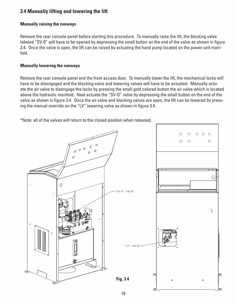
3.4 Manually lifting and lowering the lift
Manually raising the runways
Remove the rear console panel before starting this procedure. To manually raise the lift, the blocking valve labeled “SV-0” will have to be opened by depressing the small button on the end of the valve as shown in figure 3.4. Once the valve is open, the lift can be raised by actuating the hand pump located on the power unit mani-fold.
Manually lowering the runways
Remove the rear console panel and the front access door. To manually lower the lift, the mechanical locks will have to be disengaged and the blocking valve and lowering valves will have to be actuated. Manually actu-ate the air valve to disengage the locks by pressing the small gold colored button the air valve which is located above the hydraulic manifold. Next actuate the “SV-O” valve by depressing the small button on the end of the valve as shown in figure 3.4. Once the air valve and blocking valves are open, the lift can be lowered by press-ing the manual override on the “LV” lowering valve as shown in figure 3.4.
*Note: all of the valves will return to the closed position when released.
Fig. 3.4

20
Shutting down
WARNING
High electrical voltage
Severe injury or death from electrical shock
• Only trained electricians may work on the electrical system.
4.1 Temporary shutdown
Shutting down at the end of a work shift
• Lower the platform completely.
• Turn the main switch to "0".
Shutting down for storage
• Lower the platform completely.
• Disconnect the machine from the mains electricity supply.
• Transport it to the storage site.
• Carry out corrosion protection measures appropriate for the storage conditions and length of time to be stored.
• When putting the machine back into operation, perform commissioning and an additional inspection (Chap. 2.1"Starting up", page 13, Chap. 5.4.2 "Additional inspections", page 23).
4.2 Permanent shutdown The handling and disposal of mineral-based oils is subject to legal regulations. Bring used oil to an authorized collection point. For more information, contact the responsible administrative offices. Take care not to spill any hydraulic oil. Take measures to prevent spills of hydraulic oil (oil-tight tarp, catch pan).
Proceed as follows:
• Clean the machine of coarse dirt.
• Lower the platform completely.
• Disconnect the machine from the mains electricity supply.
The machine can now be transported.

21
Maintenance and inspections
5.1 Basic safety instructions
CAUTION
Hydraulic oils, lubricants and cleansers
Irritation or chemical burning of eyes, skin or respiratory tract
• Observe the safety instructions of the manufacturer.
• Use personal protective equipment.
• Use a breathing protection mask if necessary.
• Avoid contact with the skin. Should contact with skin arise, wash thoroughly.
• In the event of contact with eyes, rinse and consult a physician.
Foreign objects in the danger zone (Fig. 1.0, page 10)
Damage to the machine
• Remove any foreign objects from the danger zone.
Before any maintenance work or inspections
• Chap. 1.0 "Basic safety instructions", page 3 should be read.
• Block unauthorized persons from accessing the work area of the machine.
• Attach or erect a notice sign prohibiting switching on the machine and informing that the machine is under-going maintenance.
• Remove the load.
• Secure the machine against unintended switching on.
• Have collection containers and oil-bonding agent ready to ensure that no hydraulic oils, lubricants or cleans-ers contaminate the floor or enter the sewer system.
The preparations are completed.
After any maintenance work or inspections
• Remove all used materials, tools or other objects from the danger zone (Fig. 1.0, page 10).
• Check the machine according to the inspection list (Chap. 5.4.3 "Inspection list", page 24).
• Ensure that all safety devices are functioning flawlessly and without restriction (Chap. 1.8 "Safety devices on the machine", page 11).
• Dispose of hydraulic oil, lubricants and cleansers in accordance with environmental regulations.
The work is completed.

22
5.2 Inspecting the bearings
Inspecting the bearings
Perform a visual check for wear. The inspection is completed.
Fig. 5.1 Bearing locations on the machine
5.3 Servicing the hydraulic system
The handling and disposal of mineral-based oils is subject to legal regulations. Bring used oil to an authorized collection point. For more information, contact the responsible administrative offices. Take care not to spill any hydraulic oil. Take measures to prevent spills of hydraulic oil (oil-tight tarp, catch pan).
5.3.1 Checking the hydraulic oil level
Checking the hydraulic oil level
• Lower the platform completely.
• The oil level should be at the top of the sight glass gauge.
• Top off the oil if needed.
The check of the hydraulic oil level is completed.
5.3.2 Changing the hydraulic oil
Changing the hydraulic oil
• Raise the platform and secure it.
• Place oil collection containers under the hydraulic cylinders.
• Detach the hydraulic hoses on the hydraulic cylinders and place the open ends in the oil collection con-tainers.
• Press the «Lift» control on the control device (Fig. 3.2, page 17) until no more hydraulic oil runs out of the hoses.
• Reattach the hydraulic hoses to the hydraulic cylinders.
• Remove the filler/breather from the tank.
• Fill up the hydraulic oil. Fill quantity: Chap. 1.1 "Technical data", page 5.
• Screw the filler/breather on the tank.
• Bleed the hydraulic system (Chap. 2.2.2 "Bleeding the hydraulic system", page 14)
The hydraulic oil change is completed.

23
5.4 Inspections
5.4.1 Regular inspections
Regular inspections of the machine are to be performed by a qualified and authorized specialist at intervals of a year at the longest.
Performing the inspection
• Copy the inspection list (Chap. 5.4.3 "Inspection list", page 24).
• Inspect every item and check it off if OK.
• Only put the machine back into operation if all points have been checked off.
• After completing the inspection, file the inspection list behind the appendix in this operating manual.
The inspection is completed.
5.4.2 Additional inspections
Additional inspections of the machine are to be performed by a qualified and authorized specialist after each servicing and every repair of a malfunction. An additional inspection is likewise re-quired if the machine is to be restarted after being temporarily put out of service.
In Germany, inspection according to GUV-G 945 must be carried out. For this, use the inspection log book in the appendix of this operating manual.
Performing the inspection
• Copy the inspection list (Chap. 5.4.3 "Inspection list", page 24).
• Inspect every item and check it off if OK.
• Only put the machine back into operation if all points have been checked off.
• After completing the inspection, file the inspection list behind the appendix in this operating manual.
The inspection is completed.

24
5.4.3 Inspection list
Sequential no.:Machine type:Machine no.:Inspector:
Mechanical system
Cylinder studs securedScissors bolts securedMachine in clean conditionNotices present and legibleWelded points undamagedAll screw connections are tightResting bolts secured at proper height (4-3/4”)
Hydraulic system
No leaks in the hydraulic systemOil level is sufficient No damage of the hosesHydraulic hoses not more than 6 years oldMachine holds load at least 10 minutes in the highest position
Electrical system
Cables and cable grips tightCables are secured No damage of the cablesUpper position sensor stops the lifting motionEuro Stop sensor stops the lowering motion

25
6.1 Help for malfunctions
Please contact our customer service department. This prevents damage due to improperly performed work, saves time and avoids unnecessary costs.
6.2 Machine does not lift
6.3 Machine does not reach the full lift height
6.4 Electric motor does not run
Cause Solution
Machine overloaded Reduce the loadLeak in hydraulic system • Tighten screw connections
• Reseal hydraulic cylinders • Replace hydraulic cylinders • Replace hydraulic hoses
Pump does not build up any pressure Replace hydraulic unit Motor turning in wrong direction Check the rotational direction of the
voltage supply (only for rotary current)Factory supplies a right-rotating field
Top sensor position was reached Lower platformSwitching valve defective Replace switching valve Solenoid on lowering valve defectiveLowering valve defective Solenoid valve plug defectiveController fuse defective Replace controller fuse
Replace the solenoidReplace lowering valve Replace solenoid valve plug
Cause Solution
lio pu poTAdjust sensor
wol oot level liOSensor not correctly set
Cause Solution
Current supply interrupted• Check fuse• Check supply line
• Check motor protection switch tinu ciluardyh ecalpeRevitcefed rotoM

26
6.5 Machine does not lower (completely down)
6.7 Oil leak
6.8 Machine deflects heavily when load is changed
Cause Solution
Obstacle (dirt) in the area of the roller bearings
Clean the area of the roller bearings
Solenoid on lowering valve defective Replace the solenoid Lowering valve defective Replace lowering valve Solenoid valve plug defective Replace solenoid valve plugController fuse defective Replace controller fuseLine-break safety device triggered Identify and replace the defective
component
6.6 Machine does not lower at all
Cause Solution
Diode(s) have failed, causing PLC switches to short
Replace all diodes on PLC with FA9194
Cause Solution
Leak in hydraulic system • Tighten screw connections• Reseal hydraulic cylinders • Replace hydraulic cylinders • Replace hydraulic hoses
Cause Solution
Air in hydraulic system Bleed hydraulic system

27
VAS6131-9802-6VAS6131-9802-6
ML50-9802-12
ML50-9802-12
ML50-9802-7
ML50-9801-920 L=450
ML50-9801-930 L=500
ML50-9801-920 L=450
ML50-9801-920= L450
ML50-9801-930= L500
ML50-9801-920 L=450
ML50-9802-3
ML50-9802-3
ML50-9802-3
ML50-9802-10
ML50-9802-10
ML50-9802-13
ML50-9802-13
ML50-9802-3
ML50-9801-A2 L=3000
ML50-9801-B2 L=3000
ML50-9802-12
CB
A
ML50-9802-12 M
L50-9802-12
ML50-9802-13
ML50-9801-B1 L=3000
ML50-9801-E L=1535
ML50-9801-F L=1645
ML50-9801-A1 L=4590
ML50-9802-7
ML50-9802-7
ML50-9802-7

Vehicle Service GroupSM
2700 Lanier DriveMadison, IN 47250, USA1-800-640-5438www.vsgdover.com
© Vehicle Service GroupSM
All Rights Reserved. Unless otherwise indicated, Vehicle Service GroupSM, and all other trademarks are property of Dover Corporation and its affiliates.
SM