MKS Type PDR 2000 Dual Capacitance Diaphragm Gauge...
54
129097-P1 Rev A, 04/01 Instruction Manual MKS Type PDR 2000 Dual Capacitance Diaphragm Gauge Controller Six Shattuck Road Andover, MA 01810-2449 (800) 227-8766 or (978) 975-2350 Fax: (978) 975-0093 E-mail: [email protected] Web site: http://www.mksinst.com
Transcript of MKS Type PDR 2000 Dual Capacitance Diaphragm Gauge...

129097-P1
Rev A, 04/01
Instruction Manual
MKS Type PDR 2000Dual Capacitance Diaphragm
Gauge Controller
Six Shattuck Road
Andover, MA 01810-2449
(800) 227-8766 or (978) 975-2350
Fax: (978) 975-0093
E-mail: [email protected]
Web site: http://www.mksinst.com

WARRANTYType PDR 2000 Equipment
MKS Instruments, Inc. (M KS) warrants that for two years from the date of shipmentthe equipment described above (the “equipment”) manufactured by M KS shall befree from defects in materials and workmanship and will correctly perform all date-related operations, including without limitation accepting data entry, sequencing,sorting, comparing, and reporting, regardless of the date the operation is performedor the date involved in the operation, provided that, if the equipment exchangesdata or is otherwise used with equipment, software, or other products of others,such products of others themselves correctly perform all date-related operationsand store and transmit dates and date-related data in a format compatible withM KS equipment. THIS W ARRANTY IS M KS’ SOLE W ARRANTY CONCERNINGDATE-RELATED OPERATIONS.
For the period commencing with the date of shipment of this equipment and endingtwo years later, M KS will, at its option, either repair or replace any part which isdefective in materials or workmanship or with respect to the date-related operationswarranty without charge to the purchaser. The foregoing shall constitute theexclusive and sole remedy of the purchaser for any breach by M KS of thiswarranty.
The purchaser, before returning any equipment covered by this warranty, which isasserted to be defective by the purchaser, shall make specific written arrange-ments with respect to the responsibility for shipping the equipment and handlingany other incidental charges with the M KS sales representative or distributor fromwhich the equipment was purchased or, in the case of a direct purchase from M KS ,with the M KS home office in Andover, Massachusetts, USA.
This warranty does not apply to any equipment which has not been installed andused in accordance with the specifications recommended by M KS for the properand normal use of the equipment. M KS shall not be liable under any circumstancesfor indirect, spec ial, consequential, or incidental damages in connection with, orarising out of, the sale, performance, or use of the equipment covered by thiswarranty.
M KS recommends that all M KS pressure and flow products be calibratedperiodically (typically every 6 to 12 months) to ensure accurate readings. W hen aproduct is returned to M KS for this periodic re-calibration it is considered normalpreventative maintenance not covered by any warranty.
THIS W ARRANTY IS IN LIEU OF ALL OTHER RELEVANT W ARRANTIES,EXPRESSED OR IMPLIED, INCLUDING THE IMPLIED W ARRANTY OFMERCHANTABILITY AND THE IMPLIED W ARRANTY OF FITNESS FOR APARTICULAR PURPOSE, AND ANY W ARRANTY AGAINST INFRINGEMENT OFANY PATENT.
04/01 129097-P1 Rev A

MKS Type PDR 2000Dual Capacitance Diaphragm
Gauge Controller

Copyright © 2001 by MKS Instruments, Inc.
All rights reserved. No part of this work may be reproduced or transmitted in any form or by any means,electronic or mechanical, including photocopying and recording, or by any information storage orretrieval system, except as may be expressly permitted in writing by MKS Instruments, Inc.
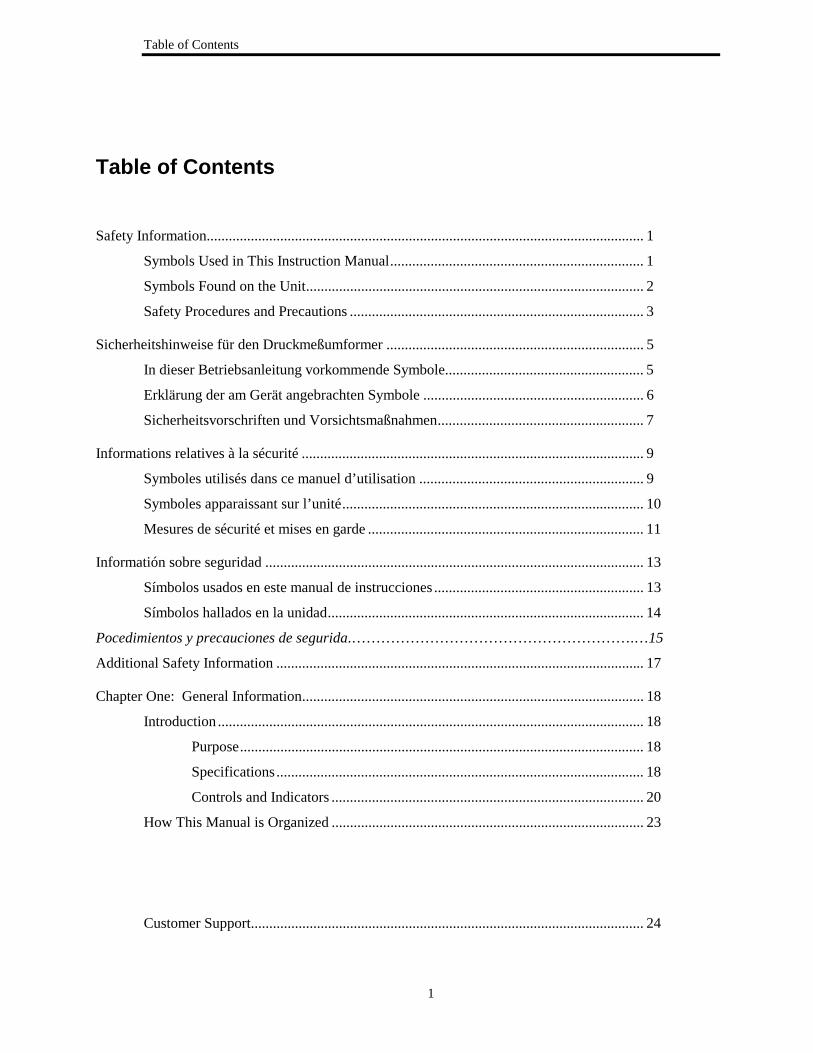
Table of Contents
1
Table of Contents
Safety Information....................................................................................................................... 1
Symbols Used in This Instruction Manual..................................................................... 1
Symbols Found on the Unit............................................................................................ 2
Safety Procedures and Precautions ................................................................................ 3
Sicherheitshinweise für den Druckmeßumformer ...................................................................... 5
In dieser Betriebsanleitung vorkommende Symbole...................................................... 5
Erklärung der am Gerät angebrachten Symbole ............................................................ 6
Sicherheitsvorschriften und Vorsichtsmaßnahmen........................................................ 7
Informations relatives à la sécurité ............................................................................................. 9
Symboles utilisés dans ce manuel d’utilisation ............................................................. 9
Symboles apparaissant sur l’unité.................................................................................. 10
Mesures de sécurité et mises en garde ........................................................................... 11
Informatión sobre seguridad ....................................................................................................... 13
Símbolos usados en este manual de instrucciones ......................................................... 13
Símbolos hallados en la unidad...................................................................................... 14
Pocedimientos y precauciones de segurida.………………………………………………….…15
Additional Safety Information .................................................................................................... 17
Chapter One: General Information............................................................................................. 18
Introduction .................................................................................................................... 18
Purpose.............................................................................................................. 18
Specifications.................................................................................................... 18
Controls and Indicators ..................................................................................... 20
How This Manual is Organized ..................................................................................... 23
Customer Support........................................................................................................... 24


Table of Contents
2
Chapter Two: Installation........................................................................................................... 25
How To Unpack the PDR 2000 Controller .................................................................... 25
Unpacking Checklist ......................................................................................... 25
Mounting the Controller................................................................................................. 26
Selecting the CDG.......................................................................................................... 26
Connecting the CDG...................................................................................................... 26
Attaching the CDG Cable .............................................................................................. 26
Making Accessory Connections........................................................................ 29
Checking Supply Voltage ................................................................................. 30
Attaching the Power Cord................................................................................. 30
Chapter 3: Operation................................................................................................................... 31
Sequence After Power Being Turned On....................................................................... 31
Front Panel Controls ...................................................................................................... 31
Description of Parameter Selection and Adjustment ..................................................... 32
Set Pt 1 High ..................................................................................................... 32
Set Pt 1 Low...................................................................................................... 32
Set Pt 2 High ..................................................................................................... 33
Set Pt 2 Low...................................................................................................... 33
Units mTorr/Torr/kTorr—Bar/mBar/microBar—Pascal/kPascal—Arb .......... 33
Calibrate ............................................................................................................ 33
Full Scale........................................................................................................... 34
Zero ................................................................................................................... 34
Reset of Stored (Default) Values ...................................................................... 35
Set Point Operation ........................................................................................... 35
Reading Pressure............................................................................................... 36
Analog Output................................................................................................... 37
Serial Interface .................................................................................................. 38
The Commands Used in the PDR 2000: ........................................................................ 38
Pressure ............................................................................................................. 38
Full Scale Of the Gauges .................................................................................. 40
Units of Measurement....................................................................................... 41
Set Point #1 ....................................................................................................... 41
Set Point #2 ...................................................................................................... 41
Model and Software Revision........................................................................... 41

3
Chapter Four: Maintenance and Troubleshooting ..................................................................... 42
Changing Fuses .............................................................................................................. 42
Schematic Diagrams....................................................................................................... 42
Trouble Shooting............................................................................................................ 42
Index............................................................................................................................................ 44
4
List of Figures and Tables
Figures
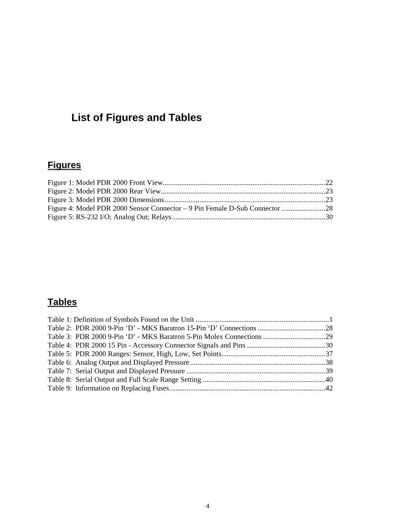
Figure 1: Model PDR 2000 Front View.........................................................................................22Figure 2: Model PDR 2000 Rear View..........................................................................................23Figure 3: Model PDR 2000 Dimensions........................................................................................23Figure 4: Model PDR 2000 Sensor Connector – 9 Pin Female D-Sub Connector ........................28Figure 5: RS-232 I/O; Analog Out; Relays ....................................................................................30
Tables
Table 1: Definition of Symbols Found on the Unit .........................................................................1Table 2: PDR 2000 9-Pin ‘D’ - MKS Baratron 15-Pin ‘D’ Connections .....................................28Table 3: PDR 2000 9-Pin ‘D’ - MKS Baratron 5-Pin Molex Connections ..................................29Table 4: PDR 2000 15 Pin - Accessory Connector Signals and Pins ...........................................30Table 5: PDR 2000 Ranges: Sensor, High, Low, Set Points.........................................................37Table 6: Analog Output and Displayed Pressure ..........................................................................38Table 7: Serial Output and Displayed Pressure ............................................................................39Table 8: Serial Output and Full Scale Range Setting ...................................................................40Table 9: Information on Replacing Fuses .....................................................................................42
Safety information Symbols used in This Instructions manual
5
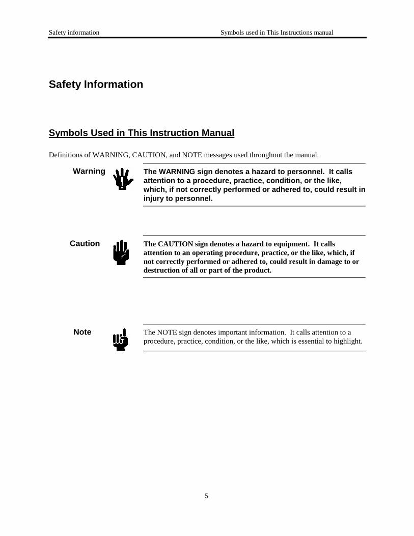
Safety Information
Symbols Used in This Instruction Manual
Definitions of WARNING, CAUTION, and NOTE messages used throughout the manual.
Warning The WARNING sign denotes a hazard to personnel. It callsattention to a procedure, practice, condition, or the like,which, if not correctly performed or adhered to, could result ininjury to personnel.
Caution The CAUTION sign denotes a hazard to equipment. It callsattention to an operating procedure, practice, or the like, which, ifnot correctly performed or adhered to, could result in damage to ordestruction of all or part of the product.
Note The NOTE sign denotes important information. It calls attention to aprocedure, practice, condition, or the like, which is essential to highlight.
Safety information Symbols used in This Instructions manual
6
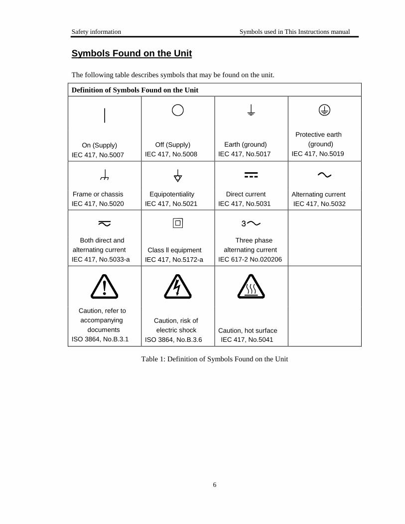
Symbols Found on the Unit
The following table describes symbols that may be found on the unit.
Definition of Symbols Found on the Unit
|
On (Supply) IEC 417, No.5007
Off (Supply)IEC 417, No.5008
Earth (ground) IEC 417, No.5017
Protective earth (ground)
IEC 417, No.5019
Frame or chassis IEC 417, No.5020
Equipotentiality IEC 417, No.5021
Direct current IEC 417, No.5031
Alternating currentIEC 417, No.5032
Both direct andalternating currentIEC 417, No.5033-a
Class ll equipment IEC 417, No.5172-a
Three phasealternating current
IEC 617-2 No.020206
Caution, refer toaccompanying
documentsISO 3864, No.B.3.1
Caution, risk ofelectric shock
ISO 3864, No.B.3.6Caution, hot surfaceIEC 417, No.5041
Table 1: Definition of Symbols Found on the Unit
Safety information Safety Procedures and Precautions
7
Safety Procedures and Precautions
The following general safety precautions must be observed during all phases of operation of thisinstrument. Failure to comply with these precautions or with specific warnings elsewhere in thismanual violates safety standards of intended use of the instrument and may impair the protectionprovided by the equipment. MKS Instruments, Inc. assumes no liability for the customer’s failureto comply with these requirements.
DO NOT SUBSTITUTE PARTS OR MODIFY INSTRUMENT
Do not install substitute parts or perform any unauthorized modification to the instrument. Return theinstrument to an MKS Calibration and Service Center for service and repair to ensure that all safetyfeatures are maintained.
SERVICE BY QUALIFIED PERSONNEL ONLY
Operating personnel must not remove instrument covers. Component replacement and internaladjustments must be made by qualified service personnel only.
GROUNDING THE PRODUCT
This product is grounded through the grounding conductor of the power cord. To avoid electrical shock,plug the power cord into a properly wired receptacle before connecting it to the product input or outputterminals. A protective ground connection by way of the grounding conductor in the power cord isessential for safe operation.
DANGER ARISING FROM LOSS OF GROUND
Upon loss of the protective-ground connection, all accessible conductive parts (including knobs andcontrols that may appear to be insulating) can render an electrical shock.
GROUND AND USE PROPER ELECTRICAL FITTINGS
Dangerous voltages are contained within this instrument. All electrical fittings and cables must be of thetype specified, and in good condition. All electrical fittings must be properly connected and grounded.
USE THE PROPER POWER CORD
Use only a power cord that is in good condition and which meets the input power requirements specifiedin the manual.
Use only a detachable cord set with conductors that have a cross-sectional area equal to or greater than0.75 mm2. The power cable should be approved by a qualified agency such as VDE, Semko, or SEV

8
USE THE PROPER POWER SOURCEThis product is intended to operate from a power source that does not apply more voltage betweenthe supply conductors, or between either of the supply conductors and ground, than that specifiedin the manual
USE THE PROPER FUSEUse only a fuse of the correct type, voltage rating, and current rating, as specified for your product
DO NOT OPERATE IN EXPLOSIVE ATMOSPHERESTo avoid explosion, do not operate this product in an explosive environment unless it has beenspecifically certified for such operation.
HIGH VOLTAGE DANGERHigh voltage is present in the cable, and in the sensor when the controller is turned on.

9
Sicherheitshinweise
In dieser Betriebsanleitung vorkommende Symbole
Definition der mit WARNUNG!, VORSICHT! und HINWEIS überschriebenen Abschnitte in dieserBetriebsanleitung.
Warnung! Das Symbol WARNUNG! weist auf eine Gefahrenquelle hin. Esmacht auf einen Arbeitsablauf, eine Arbeitsweise, einenZustand oder eine sonstige Gegebenheit aufmerksam, derenunsachgemäße Ausführung bzw. ungenügendeBerücksichtigung zu Körperverletzung führen kann.
Vorsicht! Das Symbol VORSICHT! weist auf eine Gefahrenquelle hin. Esmacht auf einen Bedienungsablauf, eine Arbeitsweise oder einesonstige Gegebenheit aufmerksam, deren unsachgemäße Ausführungbzw. Ungenügende Berücksichtigung zu einer Beschädigung oderZerstörung des Produkts oder von Teilen des Produkts führen kann.
Hinweis Das Symbol HINWEIS weist auf eine wichtige Mitteilung hin, die aufeinen Arbeitsablauf, eine Arbeitsweise, einen Zustand oder eine sonstigeGegebenheit von besonderer Wichtigkeit aufmerksam macht.
Sicherheitsinweise Am Gerät angebrachte Symbole
10
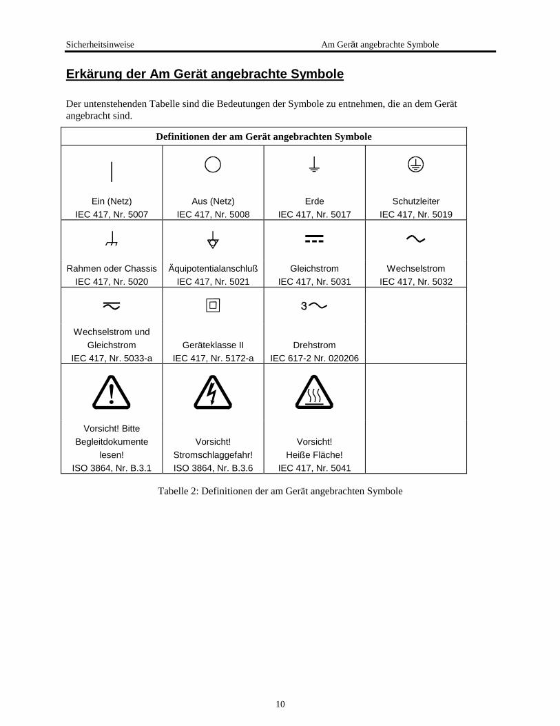
Erkärung der Am Gerät angebrachte Symbole
Der untenstehenden Tabelle sind die Bedeutungen der Symbole zu entnehmen, die an dem Gerätangebracht sind.
Definitionen der am Gerät angebrachten Symbole
|Ein (Netz)
IEC 417, Nr. 5007Aus (Netz)
IEC 417, Nr. 5008Erde
IEC 417, Nr. 5017Schutzleiter
IEC 417, Nr. 5019
Rahmen oder ChassisIEC 417, Nr. 5020
ÄquipotentialanschlußIEC 417, Nr. 5021
GleichstromIEC 417, Nr. 5031
WechselstromIEC 417, Nr. 5032
Wechselstrom undGleichstrom
IEC 417, Nr. 5033-aGeräteklasse II
IEC 417, Nr. 5172-aDrehstrom
IEC 617-2 Nr. 020206
Vorsicht! BitteBegleitdokumente
lesen!ISO 3864, Nr. B.3.1
Vorsicht!Stromschlaggefahr!ISO 3864, Nr. B.3.6
Vorsicht!Heiße Fläche!
IEC 417, Nr. 5041
Tabelle 2: Definitionen der am Gerät angebrachten Symbole

11
Sicherheitsvorschriften und Vorsichtsmaßnahmen
Die untenstehenden allgemeinen Sicherheitsvorschriften sind bei allen Betriebs-phasen diesesInstruments zu befolgen. Jede Mißachtung dieser Sicherheits-vorschriften oder sonstigerspezifischer Warnhinweise in dieser Betriebsanleitung stellt eine Zuwiderhandlung der für diesesInstrument geltenden Sicherheits-standards dar und kann die an diesem Instrument vorgesehenenSchutzvor-richtungen unwirksam machen. MKS Instruments, Inc. haftet nicht für eineMißachtung dieser Sicherheitsvorschriften seitens des Kunden.
Keine Teile austauschen und keine Veränderungen vornehmen!
Bauen Sie in das Instrument keine Ersatzteile ein, und nehmen Sie keine eigenmächtigen Änderungen amGerät vor! Schicken Sie das Instrument zu Wartungs- und Reparatur-zwecken an einen MKS-Kalibrierungs- und -Kundendienst ein! Dadurch wird sicher-gestellt, daß alle Sicherheitseinrichtungenvoll funktionsfähig bleiben.
Wartung nur durch qualifizierte Fachleute!
Das Gehäuse des Instruments darf vom Bedienpersonal nicht geöffnet werden. Das Auswechseln vonBauteilen und das Vornehmen von internen Einstellungen ist nur von qualifizierten Fachleutendurchzuführen.
Produkt erden!
Dieses Produkt ist mit einer Erdleitung und einem Schutzkontakt am Netzstecker versehen. Um derGefahr eines elektrischen Schlages vorzubeugen, ist das Netzkabel an einer vorschriftsmäßig geerdetenSchutzkontaktsteckdose anzuschließen, bevor es an den Eingangs- bzw. Ausgangsklemmen des Produktsangeschlossen wird. Das Instrument kann nur sicher betrieben werden, wenn es über den Erdleiter desNetzkabels und einen Schutzkontakt geerdet wird.
Gefährdung durch Verlust der Schutzerdung!
Geht die Verbindung zum Schutzleiter verloren, besteht an sämtlichen zugänglichen Teilen ausstromleitendem Material die Gefahr eines elektrischen Schlages. Dies gilt auch für Knöpfe und andereBedienelemente, die dem Anschein nach isoliert sind.

Sicherheitsvorschriften und VorsichtsmaBnahmen sicherheitshinweise
12
Erdung und Verwendung geeigneter elektrischer Armaturen!
In diesem Instrument liegen gefährliche Spannungen an. Alle verwendeten elektrischen Armaturen undKabel müssen dem angegebenen Typ entsprechen und sich in einwand-freiem Zustand befinden. Alleelektrischen Armaturen sind vorschriftsmäßig anzubringen und zu erden.
Richtiges Netzkabel verwenden!
Das verwendete Netzkabel muß sich in einwandfreiem Zustand befinden und den in derBetriebsanleitung enthaltenen Anschlußwerten entsprechen.
Das Netzkabel muß abnehmbar sein. Der Querschnitt der einzelnen Leiter darf nicht weniger als 0,75mm2 betragen. Das Netzkabel sollte einen Prüfvermerk einer zuständigen Prüfstelle tragen, z.B. VDE,Semko oder SEV.
Richtige Stromquelle verwenden!
Dieses Produkt ist für eine Stromquelle vorgesehen, bei der die zwischen den Leitern bzw. zwischenjedem der Leiter und dem Masseleiter anliegende Spannung den in dieser Betriebsanleitung angegebenenWert nicht überschreitet.
Richtige Sicherung benutzen!
Es ist eine Sicherung zu verwenden, deren Typ, Nennspannung und Nennstromstärke den Angaben fürdieses Produkt entsprechen.
Gerät nicht in explosiver Atmosphäre benutzen!
Um der Gefahr einer Explosion vorzubeugen, darf dieses Gerät nicht in der Nähe explosiver Stoffeeingesetzt werden, sofern es nicht ausdrücklich für diesen Zweck zertifiziert worden ist.
Hochspannungsgefahr!
Bei eingeschaltetem Steuerteil liegt im Kabel und im Sensor Hochspannung an.
13
Informations relatives à la sécurité Pour le trangdueteur depression
Symboles utilisés dans ce manuel d’utilisation
Définition des indications AVERTISSEMENT, ATTENTION et REMARQUE utilisées dans ce manuel.
Avertissement L’indication AVERTISSEMENT signale un danger potentiel. Elleest destinée à attirer l’attention sur une procédure, uneutilisation, une situation ou toute autre chose présentant unrisque de blessure en cas d’exécution incorrecte ou de non-respect des consignes.
Attention L’indication ATTENTION signale un danger potentiel. Elle estdestinée à attirer l’attention sur une procédure, une utilisation, unesituation ou toute autre chose présentant un risque d’endommagementou de dégât d’une partie ou de la totalité de l’appareil en casd’exécution incorrecte ou de non-respect des consignes.
Remarque L’indication REMARQUE signale des informations importantes. Elle estdestinée à attirer l’attention sur une procédure, une utilisation, une situationou toute autre chose présentant un intérêt particulier.
Informations relatives à la sécurité Symboles apparaissant sur l’ appareil
14
Symboles apparaissant sur l’appareil
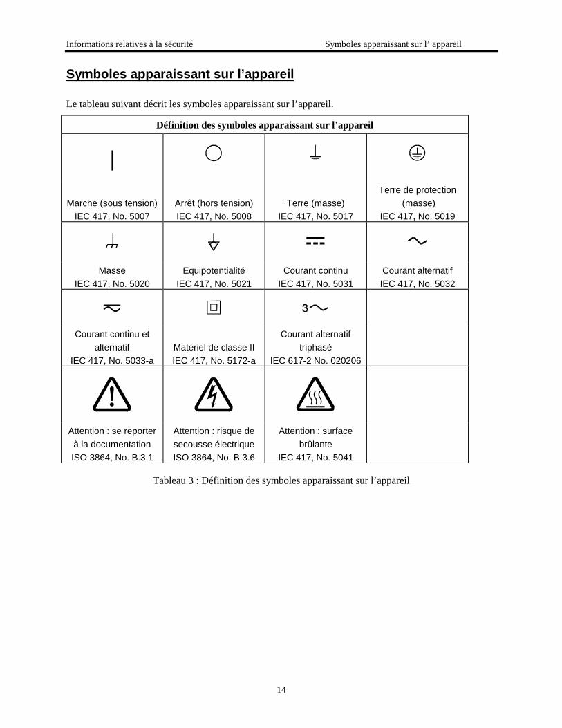
Le tableau suivant décrit les symboles apparaissant sur l’appareil.
Définition des symboles apparaissant sur l’appareil
|
Marche (sous tension)IEC 417, No. 5007
Arrêt (hors tension)IEC 417, No. 5008
Terre (masse)IEC 417, No. 5017
Terre de protection (masse)
IEC 417, No. 5019
MasseIEC 417, No. 5020
EquipotentialitéIEC 417, No. 5021
Courant continuIEC 417, No. 5031
Courant alternatifIEC 417, No. 5032
Courant continu etalternatif
IEC 417, No. 5033-aMatériel de classe IIIEC 417, No. 5172-a
Courant alternatiftriphasé
IEC 617-2 No. 020206
Attention : se reporterà la documentationISO 3864, No. B.3.1
Attention : risque desecousse électriqueISO 3864, No. B.3.6
Attention : surfacebrûlante
IEC 417, No. 5041
Tableau 3 : Définition des symboles apparaissant sur l’appareil
15
Mesures de sécurité et mises en garde
Prendre toutes les précautions générales suivantes pendant toutes les phases d’utilisation de cetappareil. Le non-respect de ces précautions ou des avertissements contenus dans ce manuelentraîne une violation des normes de sécurité relatives à l’utilisation de l’appareil et le risque deréduire le niveau de protection fourni par l’appareil. MKS Instruments, Inc. ne prend aucuneresponsabilité pour les conséquences de tout non-respect des consignes de la part de ses clients.
NE PAS SUBSTITUER DES PIÈCES OU MODIFIER L’APPAREIL
Ne pas utiliser de pièces détachées autres que celles vendues par MKS Instruments, Inc. ou modifierl’appareil sans l’autorisation préalable de MKS Instruments, Inc. Renvoyer l’appareil à un centred’étalonnage et de dépannage MKS pour tout dépannage ou réparation afin de s’assurer que tous lesdispositifs de sécurité sont maintenus.
DÉPANNAGE EFFECTUÉ UNIQUEMENT PAR UN PERSONNEL QUALIFIÉ
L’opérateur de l’appareil ne doit pas enlever le capot de l’appareil. Le remplacement des composants etles réglages internes doivent être effectués uniquement par un personnel d’entretien qualifié.
MISE À LA TERRE DE L’APPAREIL
Cet appareil est mis à la terre à l’aide du fil de terre du cordon d’alimentation. Pour éviter tout risque desecousse électrique, brancher le cordon d’alimentation sur une prise de courant correctement câblée avantde le brancher sur les bornes d’entrée ou de sortie de l’appareil. Une mise à la terre de protection à l’aidedu fil de terre du cordon d’alimentation est indispensable pour une utilisation sans danger de l’appareil.
DANGER LIÉ À UN DÉFAUT DE TERRE
En cas de défaut de terre, toutes les pièces conductrices accessibles (y compris les boutons de commandeou de réglage qui semblent être isolés) peuvent être source d’une secousse électrique.
MISE À LA TERRE ET UTILISATION CORRECTE D’ACCESSOIRES ÉLECTRIQUES
Des tensions dangereuses existent à l’intérieur de l’appareil. Tous les accessoires et les câbles électriquesdoivent être conformes au type spécifié et être en bon état. Tous les accessoires électriques doivent êtrecorrectement connectés et mis à la terre.
Mesures de sécurité et mises en garde Informations relatives à la sécurité
16
UTILISATION D’UN CORDON D’ALIMENTATION APPROPRIÉ
Utiliser uniquement un cordon d’alimentation en bon état et conforme aux exigences de puissanced’entrée spécifiées dans le manuel.
Utiliser uniquement un cordon d’alimentation amovible avec des conducteurs dont la section est égale ousupérieure à 0,75 mm2. Le cordon d’alimentation doit être approuvé par un organisme compétent tel queVDE, Semko ou SEV.
UTILISATION D’UNE ALIMENTATION APPROPRIÉE
Cet appareil est conçu pour fonctionner en s’alimentant sur une source de courant électrique n’appliquantpas une tension entre les conducteurs d’alimentation, ou entre les conducteurs d’alimentation et leconducteur de terre, supérieure à celle spécifiée dans le manuel.
UTILISATION D’UN FUSIBLE APPROPRIÉ
Utiliser uniquement un fusible conforme au type, à la tension nominale et au courant nominal spécifiéspour l’appareil.
NE PAS UTILISER DANS UNE ATMOSPHÈRE EXPLOSIVE
Pour éviter tout risque d’explosion, ne pas utiliser l’appareil dans une atmosphère explosive à moins qu’iln’ait été approuvé pour une telle utilisation.
DANGER DE HAUTE TENSION
Une haute tension est présente dans le câble et dans le capteur lorsque le contrôleur est sous tension.
17
Información sobre seguridad
Símbolos usados en el manual de instrucciones
Definiciones de los mensajes de ADVERTENCIA, PRECAUCIÓN Y OBSERVACIÓN usados en elmanual.
Advertencia El símbolo de ADVERTENCIA indica un riesgo. Pone derelieve un procedimiento, práctica, condición, etc., que, de norealizarse u observarse correctamente, podría causar lesionesa los empleados.
Precaución El símbolo de PRECAUCIÓN indica un riesgo. Pone de relieve unprocedimiento, práctica, etc., de tipo operativo que, de no realizarseu observarse correctamente, podría causar desperfectos alinstrumento, o llegar incluso a causar su destrucción total o parcial.
Observación El símbolo de OBSERVACIÓN indica información de importancia. Ponede relieve un procedimiento, práctica, condición, etc., cuyo conocimientoresulta esencial.
Información sobre seguridad Símbolos gue aparecen en la unidad
18
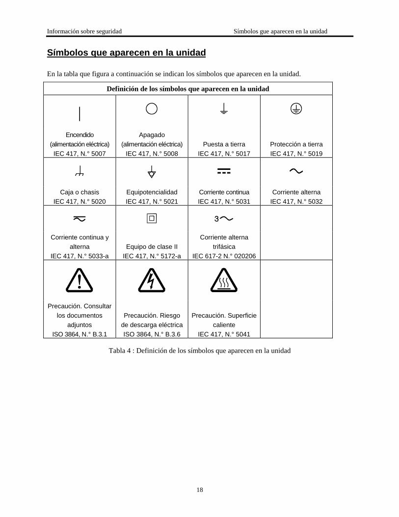
Símbolos que aparecen en la unidad
En la tabla que figura a continuación se indican los símbolos que aparecen en la unidad.
Definición de los símbolos que aparecen en la unidad
|Encendido
(alimentación eléctrica)IEC 417, N.° 5007
Apagado(alimentación eléctrica)
IEC 417, N.° 5008Puesta a tierra
IEC 417, N.° 5017Protección a tierraIEC 417, N.° 5019
Caja o chasisIEC 417, N.° 5020
EquipotencialidadIEC 417, N.° 5021
Corriente continuaIEC 417, N.° 5031
Corriente alternaIEC 417, N.° 5032
Corriente continua yalterna
IEC 417, N.° 5033-aEquipo de clase II
IEC 417, N.° 5172-a
Corriente alternatrifásica
IEC 617-2 N.° 020206
Precaución. Consultarlos documentos
adjuntosISO 3864, N.° B.3.1
Precaución. Riesgode descarga eléctricaISO 3864, N.° B.3.6
Precaución. Superficiecaliente
IEC 417, N.° 5041
Tabla 4 : Definición de los símbolos que aparecen en la unidad
19
Procedimientos y precauciones de seguridad
Las precauciones generales de seguridad que figuran a continuación deben observarse durantetodas las fases de funcionamiento del presente instrumento. La no observancia de dichasprecauciones, o de las advertencias específicas a las que se hace referencia en el manual,contraviene las normas de seguridad referentes al uso previsto del instrumento y podría impedir laprotección que proporciona el instrumento. MKS Instruments, Inc., no asume responsabilidadalguna en caso de que el cliente haga caso omiso de estos requerimientos.
NO UTILIZAR PIEZAS NO ORIGINALES NI MODIFICAR EL INSTRUMENTO
No se debe instalar piezas que no sean originales ni modificar el instrumento sin autorización. Paragarantizar que las prestaciones de seguridad se observen en todo momento, enviar el instrumento alCentro de servicio y calibración de MKS cuando sea necesaria su reparación y servicio demantenimiento.
REPARACIONES EFECTUADAS ÚNICAMENTE POR TÉCNICOS ESPECIALIZADOS
Los operarios no deben retirar las cubiertas del instrumento. El cambio de piezas y los reajustes internosdeben efectuarlos únicamente técnicos especializados.
PUESTA A TIERRA DEL INSTRUMENTO
Este instrumento está puesto a tierra por medio del conductor de tierra del cable eléctrico. Para evitardescargas eléctricas, enchufar el cable eléctrico en una toma debidamente instalada, antes de conectarlo alas terminales de entrada o salida del instrumento. Para garantizar el uso sin riesgos del instrumentoresulta esencial que se encuentre puesto a tierra por medio del conductor de tierra del cable eléctrico.
PELIGRO POR PÉRDIDA DE LA PUESTA A TIERRA
Si se pierde la conexión protectora de puesta a tierra, todas las piezas conductoras a las que se tieneacceso (incluidos los botones y mandos que pudieran parecer estar aislados) podrían producir descargareléctricas.
PUESTA A TIERRA Y USO DE ACCESORIOS ELÉCTRICOS ADECUADOS
Este instrumento funciona con voltajes peligrosos. Todos los accesorios y cables eléctricos deben ser deltipo especificado y mantenerse en buenas condiciones. Todos los accesorios eléctricos deben estarconectados y puestos a tierra del modo adecuado.
Información sobre seguridad
20
USAR EL CABLE ELÉCTRICO ADECUADO
Usar únicamente un cable eléctrico que se encuentre en buenas condiciones y que cumpla los requisitosde alimentación de entrada indicados en el manual.
Usar únicamente un cable desmontable instalado con conductores que tengan un área de seccióntransversal equivalente o superior a 0,75mm². El cable eléctrico debe estar aprobado por una entidadautorizada como, por ejemplo, VDE, Semko o SEV.
USAR LA FUENTE DE ALIMENTACIÓN ELÉCTRICA ADECUADA
Este instrumento debe funcionar a partir de una fuente de alimentación eléctrica que no aplique másvoltaje entre los conductores de suministro, o entre uno de los conductores de suministro y la puesta atierra, que el que se especifica en el manual.
USAR EL FUSIBLE ADECUADO
Usar únicamente un fusible del tipo, clase de voltaje y de corriente adecuados, según lo que se especificapara el instrumento.
EVITAR SU USO EN ENTORNOS EXPLOSIVOS
Para evitar el riesgo de explosión, no usar este instrumento o en un entorno explosivo, a no ser que hayasido certificado para tal uso.
PELIGRO POR ALTO VOLTAJE
Cuando el controlador está encendido, se registra alto voltaje en el cable y en el sensor.
Additional Safety Information
21
Warning Explosive GasesDo not use the Model PDR 2000 Dual Capacitance DiaphragmGauge Controller to measure the pressure of combustible gasmixtures. The gauge normally operates at low temperatures, but itis possible that momentary transients or controller malfunction maycause ignition of combustible mixtures, which then might explodeand cause damage to equipment and injury to personnel.
Warning Limitation on Use of Compression MountsDo not use a compression mount (quick-connect) for attaching thegauge tube to the vacuum system in applications that may developpositive pressures. Positive pressures may cause the tube to be blownout of a compression fitting and damage equipment and injurepersonnel.
Warning ChemicalsMany organic cleaning solvents, such as acetone, produce fumesthat are toxic or flammable. Use such solvents only in areas that arewell ventilated to the outdoors and away from electronic equipment,open flames, or other potential ignition sources.
Please Let Us Know...
MKS Instruments products are the most advance instruments of their type available from anymanufacturer. We have made this Instruction Manual as complete and clear as possible. Let us know ifyou have any comments that can make this manual or our products more useful.
Chapter One: General Information Introduction
22
Chapter One: General Information
IntroductionPurposeThe MKS Instruments Model PDR 2000 Dual Capacitance Diaphragm Gauge (CDG) Controllerdisplays vacuum pressure as measured from capacitance diaphragm gauges. The PDR 2000supplies �15 volts at up to 0.75 amp; this is sufficient to operate most heated capacitancediaphragm gauges. The PDR 2000 precisely measures the 0 to 10 volt signal from the CDG todetermine pressure. The Model PDR 2000 controller covers full scale ranges from 20 mTorr to10,000 Torr. The PDR 2000 is housed in a 1/8 DIN enclosure and is simple to operate.Figure 1 displays the PDR 2000 front view; Figure 2 displays the rear view and Figure 3displays the dimensions.
SpecificationsThe PDR 2000 Dual Capacitance Diaphragm Gauge has the following specifications:
Useful Measuring Range
4 decades; full scale of 20 mTorr to 10.00 ktorr; full scale range selection is entered on the frontpanel by the user.
• Display Range
• -9.9 torr to 10.00 ktorr; pressures higher than 10.00 ktorr display OFF.
• Display Resolution
Varies according to full scale range, from 0.01 mTorr to 1 Torr
Gauge Interface
The PDR 2000 incorporates a high-resolution input circuit, which allows the use of the capacitancediaphragm gauge over its entire 4 decades.
• Input to the PDR 2000 Controller
0 to 10 volts for full scale of the gauge
• Units of Display
Torr (mtorr), mBar(Bar), arb (no units), Kpa, and (Pa) user selectable
• Full Scale
User selectable range to match CDG: 20, 50, 100mTorr; 1, 2, 10, 100, 1000, 5,000 and 10,000 torr
• Calibration Adjust
• For calibration of display; allows user to multiply CDG response by 0.50 to 2.00.
•
23
• Vacuum Gauge
One or two capacitance diaphragm gauges which require up to 0.75 amp total from � 15 voltsupplies; this is sufficient to operate most heated gauges.
• Operating Temperature Range
+2 to +50 deg. Celsius
• Process Control Set Points
Two, with independent High and Low set points for each relay, for flexible control of hysteresis
• Process Control Relays
Two relays; contacts rated at 2 amp/240 VAC, 30 VDC
• Nonvolatile Memory
For all user specified parameters
• Analog Output
Logarithmic, 0.5 volts/decade; 0.10 mTorr=0.5 volts
• Output Power
+15 at 0.75 amp and –15 volts at 0.75 amp; sufficient to operate temperature-controlled gauges
• Mounting
The PDR 2000 may be used as a bench-top instrument or it may be mounted in an instrument panel.Clips are provided for panel mounting.
• RS-232 Input/Output
Allows user to read pressure and set points; 9600 baud, 8-N-1; available through the accessoryconnector.
• Operating Voltage
The Model PDR 2000 has a universal power supply, which operates on input voltages from 90 VACto 265 VAC 47 to 65 Hz; input is through a standard IEC 320 instrument power input receptacle onthe rear panel; input power is protected by fuses in both lines of the input power.
• Weight Model PDR 2000 only; does not include cable or CDG 0.9 lb. /0.4 kg.
•
Controls and Indicators• GAUGE SELECT Button

Chapter One: General Information Introduction
24
This button allows the user to select either of the two gauges that are shown on the digital display.
• SELECT Button
This button allows the user to select parameters to be adjusted, e.g. Set Points.
• RAISE and LOWER Buttons
These buttons allow the user to adjust the gauge and instrument parameters.
• Digital Display
This is a 4-digit 7-segment bright red LED, 10 mm high.
• Display Indicators
This is a bright red individual LED for miscellaneous indicators.

25
Figure 1: Model PDR 2000 Front View
Chapter One: General Information Introduction
26
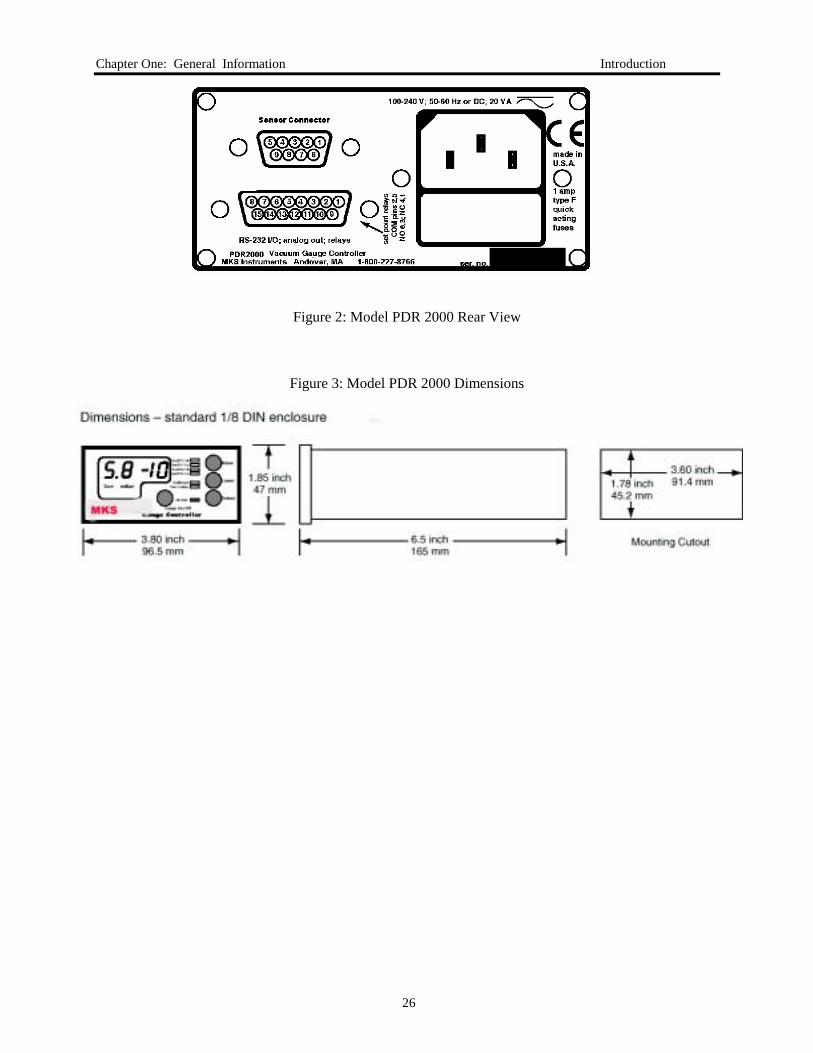
Figure 2: Model PDR 2000 Rear View
Figure 3: Model PDR 2000 Dimensions

27
How This Manual is Organized
This manual is designed to provide instructions on how to set up, install, and operate a Type PDR 2000unit.
Before installing your Type PDR 2000 unit in a system and/or operating it, carefully read andfamiliarize yourself with all precautionary notes in the Safety Messages and Procedures section atthe front of this manual. In addition, observe and obey all WARNING and CAUTION notes providedthroughout the manual.
Chapter One, General Information, (this chapter) introduces the product and describes the organizationof the manual.
Chapter Two, Installation, explains the environmental requirements and describes how to mount theinstrument in your system.
Chapter Three, Operation, describes how to use the instrument and explains all the functions andfeatures.
Chapter Four, Maintenance and Troubleshooting, lists any maintenance required to keep the instrumentin good working condition, and provides a checklist for reference should the instrument malfunction.
Chapter One: General Information
28
Customer Support
Standard maintenance and repair services are available at all of our regional MKS Calibration andService Centers, listed on the back cover. MKS also accepts the instruments of other manufacturers forrecalibration using the Primary and Transfer Standard calibration equipment at our regional servicecenters. If any difficulties arise using the Type PDR 2000 instrument, or to obtain information aboutcompanion products MKS offers, contact any authorized MKS Calibration and Service Center.
If you need to return the gauge controller to MKS Instruments for service:
1. Contact MKS Instruments to get a ERA (Equipment Return Authorization) number.
2. Pack the instrument securely.
3. Use the original packaging if it is available.
4. If the MKS Instruments PDR 2000 was shipped with a cable and/or CDG sensor, diagnosis andrepair will be more efficient if all components are returned together. If this is not convenient, pleaseconsult with your MKS Instruments Customer Service Representative
5. If you do not have appropriate packing materials, commercial packing and shipping firm can providethem.
6. Be sure to mark the ERA number on the outside of the package.
Warning All returns to MKS Instruments must be free of harmful,corrosive, radioactive, and toxic materials.

29
.
Chapter Two: Installation
How To Unpack the PDR 2000 Controller
MKS has carefully packed the Type PDR 2000 unit to reach you in perfect operating order. On receivingthe unit, however, you should check for defects, cracks, broken connectors, etc., making sure that theType PDR 2000 was not damaged during shipment.
Note Do not discard any packing materials until you have completed yourinspection and are sure the unit is intact.
If you find any damage, notify your carrier and MKS immediately. See Customer Support on page 12.Please refer to the last page of this supplement for a list of MKS Calibration and Service Centers.
Unpacking Checklist• Type PDR 2000 Unit
• Type PDR 2000 Manual (this document)
• power cord
• mounting clips
• D-sub 15 accessory connector
Caution Do not plug the power cord in yet.
Chapter Two: Installation
30
Mounting the Controller
You can rest the controller unit on a bench, tabletop, or shelf, or you can mount it on a rack or cabinet.The controller unit is housed in a standard 1/8 DIN box. If you are mounting the unit in a panel, thecutout dimensions are 1.78 inch by 3.60 inch (45.2 mm by 91.4 mm). One mounting clip attaches to eachof the ides of the controller unit. To attach the clip, slide the beveled surfaces of the clip under the cutouton the side of the box and push the clip toward the back of the unit.
Note Be sure to mount the unit with adequate space around it for proper aircirculation..
Note Be sure to leave enough clearance at the back of the controller unit foreasy access to cable connections.
Selecting the CDG
The Model PDR 2000 controller is designed to work with standard capacitance diaphragm gauges, whichoperate on ±15 volts. If you have difficulty obtaining a CDG, please contact us at MKS Instruments.
Caution Use of a CDG other than those, which operate from ± 15 volts, may causedamage to the CDG.
Connecting the CDG
Make sure that the CDG is securely connected to the vacuum system, using good vacuum practice.
Attaching the CDG Cable
The CDG cable has a 9-pin D-sub connector on one end, which plugs into the PDR 2000. There are avariety of conventions for connection to the CDG. You may assemble or modify the cable to adapt to theCDG as needed. Connect the 9-pin D-sub plug of the gauge cable to the 9-pin connector on the back ofthe PDR 2000 controller unit. Push the plug onto the connector until it
is firmly in place. Tighten the retaining screws to make certain the connector remains in place. Looseconnections can cause a faulty reading.
31
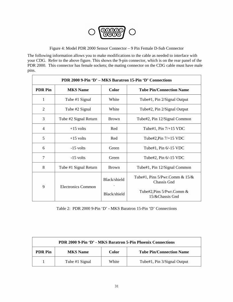
Figure 4: Model PDR 2000 Sensor Connector – 9 Pin Female D-Sub Connector
The following information allows you to make modifications to the cable as needed to interface withyour CDG. Refer to the above figure. This shows the 9-pin connector, which is on the rear panel of thePDR 2000. This connector has female sockets; the mating connector on the CDG cable must have malepins.
PDR 2000 9-Pin ‘D’ – MKS Baratron 15-Pin ‘D’ Connections
PDR Pin MKS Name Color Tube Pin/Connection Name
1 Tube #1 Signal White Tube#1, Pin 2/Signal Output
2 Tube #2 Signal White Tube#2, Pin 2/Signal Output
3 Tube #2 Signal Return Brown Tube#2, Pin 12/Signal Common
4 +15 volts Red Tube#1, Pin 7/+15 VDC
5 +15 volts Red Tube#2,Pin 7/+15 VDC
6 -15 volts Green Tube#1, Pin 6/-15 VDC
7 -15 volts Green Tube#2, Pin 6/-15 VDC
8 Tube #1 Signal Return Brown Tube#1, Pin 12/Signal Common
9 Electronics Common
Black/shield.
Black/shield
Tube#1, Pins 5/Pwr.Comm & 15/&Chassis Gnd
Tube#2,Pins 5/Pwr.Comm &15/&Chassis Gnd
Table 2: PDR 2000 9-Pin ‘D’ - MKS Baratron 15-Pin ‘D’ Connections
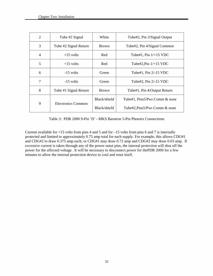
PDR 2000 9-Pin ‘D’ - MKS Baratron 5-Pin Phoenix Connections
PDR Pin MKS Name Color Tube Pin/Connection Name
1 Tube #1 Signal White Tube#1, Pin 3/Signal Output
Chapter Two: Installation
32
2 Tube #2 Signal White Tube#2, Pin 3/Signal Output
3 Tube #2 Signal Return Brown Tube#2, Pin 4/Signal Common
4 +15 volts Red Tube#1, Pin 1/+15 VDC
5 +15 volts Red Tube#2,Pin 1/+15 VDC
6 -15 volts Green Tube#1, Pin 2/-15 VDC
7 -15 volts Green Tube#2, Pin 2/-15 VDC
8 Tube #1 Signal Return Brown Tube#1, Pin 4/Output Return
9 Electronics CommonBlack/shield
Black/shield
Tube#1, Pins5/Pwr.Comm & none
Tube#2,Pins5/Pwr.Comm & none
Table 3: PDR 2000 9-Pin ‘D’ - MKS Baratron 5-Pin Phoenix Connections
Current available for +15 volts from pins 4 and 5 and for –15 volts from pins 6 and 7 is internallyprotected and limited to approximately 0.75 amp total for each supply. For example, this allows CDG#1and CDG#2 to draw 0.375 amp each; or CDG#1 may draw 0.72 amp and CDG#2 may draw 0.03 amp. Ifexcessive current is taken through any of the power outut pins, the internal protection will shut off thepower for the affected voltage. It will be necessary to disconnect power for thePDR 2000 for a fewminutes to allow the internal protection device to cool and reset itself.
33
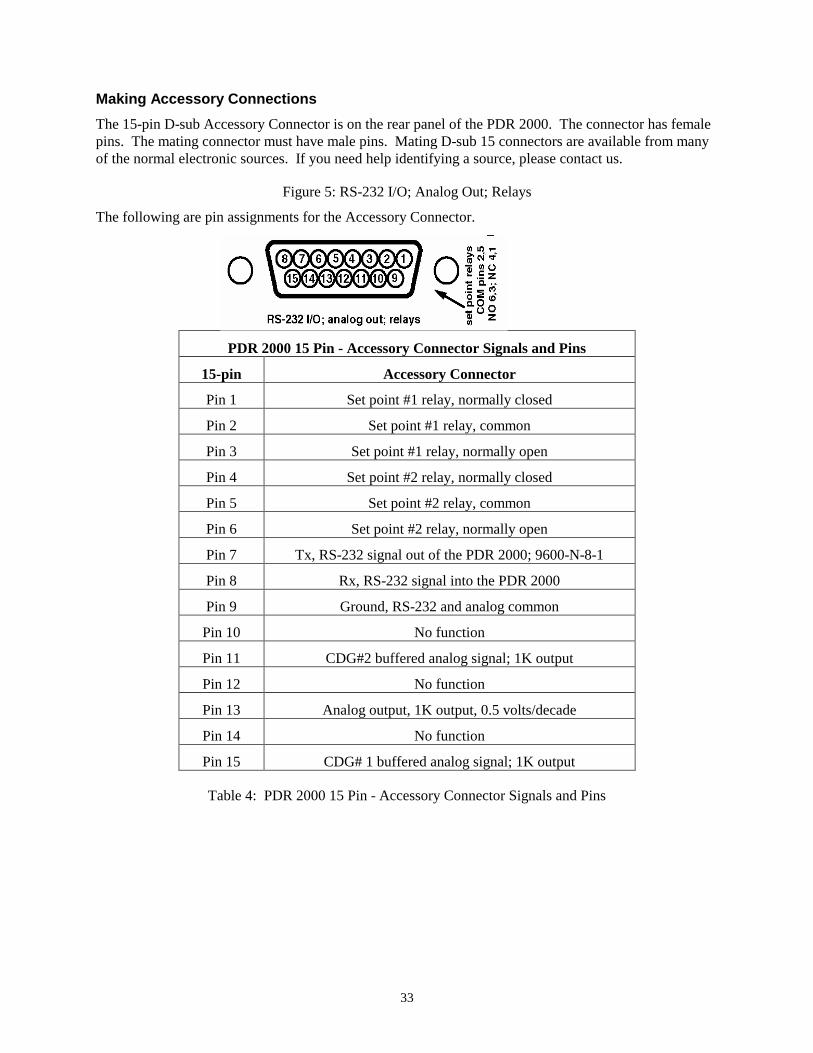
Making Accessory ConnectionsThe 15-pin D-sub Accessory Connector is on the rear panel of the PDR 2000. The connector has femalepins. The mating connector must have male pins. Mating D-sub 15 connectors are available from manyof the normal electronic sources. If you need help identifying a source, please contact us.
Figure 5: RS-232 I/O; Analog Out; Relays
The following are pin assignments for the Accessory Connector.
PDR 2000 15 Pin - Accessory Connector Signals and Pins
15-pin Accessory Connector
Pin 1 Set point #1 relay, normally closed
Pin 2 Set point #1 relay, common
Pin 3 Set point #1 relay, normally open
Pin 4 Set point #2 relay, normally closed
Pin 5 Set point #2 relay, common
Pin 6 Set point #2 relay, normally open
Pin 7 Tx, RS-232 signal out of the PDR 2000; 9600-N-8-1
Pin 8 Rx, RS-232 signal into the PDR 2000
Pin 9 Ground, RS-232 and analog common
Pin 10 No function
Pin 11 CDG#2 buffered analog signal; 1K output
Pin 12 No function
Pin 13 Analog output, 1K output, 0.5 volts/decade
Pin 14 No function
Pin 15 CDG# 1 buffered analog signal; 1K output
Table 4: PDR 2000 15 Pin - Accessory Connector Signals and Pins
Chapter Two: Installation
34
Checking Supply VoltageThe Model PDR 2000 incorporates a universal power supply. This allow the PDR 2000 to operate onany input voltage from 90 VAC to 265 VAC, 47 to 65 Hz.
Attaching the Power CordPlug the power cord into the receptacle in the power module on the rear of the PDR 2000.
35
Chapter 3: Operation
Sequence After Power Being Turned On
Plug the AC power end of the power cord into an electrical outlet. The loudspeaker will “beep” and testall indicators while the controller executes its self test. After being turned on, the instrument will gothrough the following sequence:
1. “beeper”
2. indicators for TORR, MTORR, MBAR, µBAR, Kpa, and Pa
3. 10 LED indicators for set points and other functions
4. all four digits will light, including decimal points
5. display shows the model number of the instrument, 908A
6. display shows software version, e.g. 1.10
The PDR 2000 will go into normal operation and begin measuring pressure. If the CDG is not connected,the display will show OFF. If the system pressure is greater than 10.00 ktorr, the display will show OFF.
Front Panel Controls
The Model PDR 2000 allows flexible configuration of operation using simple entry from the front panelbuttons labeled GAUGE SELECT, SELECT, RAISE and LOWER. Parameters, which you may adjust,are selected by scrolling through list that begins with SET PT 1 HIGH. Each time the SELECT button ispushed, the led indicator advances to the next parameter. The LED indicators will be lit to indicate whichparameter is being adjusted, and the digital display will flash to indicate the value of the parameter beingadjusted.
Each push of a button will give a short “beep” from the loudspeaker to confirm that the button waspushed. If you have reached the limit of adjustment or if the button push is not allowed, the loudspeakerwill give a long “beep”.
Chapter Three: Operation
36
Description of Parameter Selection and Adjustment
Set Pt 1 HighDefault Value: OFF
This sets the high limit of the set point. Above this pressure, the set point relay will be de-energized.Press the RAISE or LOWER buttons to enter the value desired. The minimum value is OFF; this shuts theset point off. The next increment is 0.2% of the full scale range. For example, if the full scale range is 1torr, the increment sequence is OFF, 2.0 mTorr, 3.0 mTorr, etc.
When the RAISE or LOWER buttons are pressed, the display will change slowly at first. If you hold thebutton down for a few seconds, the rate of change will increase to allow you to make large changes morequickly.
SET PT 1 HIGH operates in conjunction with SET PT 1 LOW. While the PDR 2000 is in this mode, theset point may be assigned to either GAGE 1 or GAGE 2 by pressing the GAUGE SELECT button.
Set Pt 1 LowDefault Value: OFF
This sets the low limit of the set point. This is the pressure at which the set point relay will be energized.Operation is similar to that of SET PT 1 HIGH above. The minimum value is OFF; this shuts the setpoint off. The next increment is 0.1% of the full scale range. For example, if the full scale range is 1 torr,the increment sequence is OFF, 1.0 mTorr, 2.0 mTorr, etc.
Note SET PT 1 LOW operates in conjunction with SET PT 1 HIGH.
Note The High and Low set point allow the user to set the hysteresis of the setpoint operation. As the system is pumped down, the set point relay willbe energized (set point turns on) as the pressure drops below SET PT 1LOW. The relay will remain energized until the pressure rises above SETPT 1 HIGH.
It is not possible to adjust the High set point to be lower than the Low set point. If you adjust the High setpoint below the pressure previously selected for the Low set point, the PDR 2000 will automaticallyreduce the value for the Low set point so that it is the next increment lower than that of the High setpoint.

37
Set Pt 2 HighDefault Value: OFF
This operates in the same manner as SET PT 1 HIGH, described above.
Set Pt 2 LowDefault Value: OFF
This operates in the same manner as SET PT 1 LOW, described above.
Units mTorr/Torr/kTorr—Bar/mBar/microBar—Pascal/kPascal—ArbDefault Value: Torr
This allows selection of the units to be used in display of the pressure. Press either the RAISE orLOWER buttons to alternate between Torr, mBar and Pascal. You will notice that both the GAGE 1andGAGE 2 indicators will be lit also. This is to let you know that the units of measure apply to both gauges;it is not possible to select Torr for one gauge and mBar for the other gauge. The “Arb” value allowsarbitrary units to be used; the value displayed is the same as for Torr units, and can be adjusted using the“Full Scale” and “Calibrate” functions.
CalibrateDefault Value: 1.00 (Internal value)
This allows the user to modify the reading for either gauge by multiplying by a value between 0.500 and2.000. This is convenient for calibration of the CDG. The CDGs are calibrated by the manufacturerbefore shipment; we suggest you use this adjustment only if you have reliable calibration data. Themultiplier is internal and is not seen by the user. The digital display shows the result of the pressuremultiplied by the internal multiplier.
This adjustment may also be used to set the display to some value that is unique to your application orexperiment.
NoteThis adjustment is applicable to either gauge; please select theappropriate gauge by pressing GAUGE SELECT until the desired gaugeis indicated. Use RAISE and LOWER as described above to set to thedesired value.
The CALIBRATE function may be adjusted only when the CDG pressure is at 50% of full scale or higher.
Full ScaleDefault Value: 1.00 Torr
Chapter Three: Operation
38
This adjustment is applicable to either gauge; please select the gauge by pressing GAUGE SELECT until thedesired gauge is indicated. Use RAISE and LOWER as described above to set to the desired value.
This allows the user to select the full scale range for each CDG. Press RAISE or LOWER to set the desiredfull scale range. The full scale ranges available are 20 mTorr, 50 mTorr, 100 mTorr, 1 Torr, 2 Torr, 10Torr, 100 Torr, 1000 Torr, 5000 Torr and 10,000 Torr.
ZeroDefault Value: 0.0 (internal value)
This allows the user to adjust the zero for each CDG. Before making this adjustment, the CDG should beconnected to a vacuum system at a pressure lower than 0.1% of the full scale for the CDG. Thisadjustment may also be used to set the display to a specific value if you know the pressure through othermeans. For example, if the CDG to be adjusted is attached to a system that has another CDG, which hasbeen independently calibrated, the CDG may be made to read the same as the calibrated gauge.
The ZERO function may be adjusted only when the CDG pressure is at 10% of full scale or lower.
NotePressing the [ZERO] key only adjusts the display! It does not adjust theoutput of the gauge or the buffered analog output.
Note INITIAL ZEROWhen installing a CDG for the first time, it is good practice to reset thePDR 2000 internal settings. This will prevent errors in set up; e.g., if theCDG has not had its internal zero properly adjusted.
To reset the PDR 2000, see Reset of Stored Values, just below.
To adjust the zero, the vacuum system to which the CDG is connectedshould be at a pressure lower than 0.001 times the full-scale range of theCDG. For example, for a 10 Torr CDG, the system should be at apressure lower than 0.01 torr, or 10 -2 torr.
Adjust the zero adjustment on the CDG (usually a trimpot) until the PDR 2000 display shows a valueclose to zero. After this initial adjustment, the display may be conveniently set to zero using front panelcontrols on the Model PDR 2000.
37
Note HEATED CDGsWhen using heated or temperature-controlled CDGs, you should wait fourhours before adjusting the PDR 2000 or the CDG. This will allow theCDG to come to its regulated temperature. When you are confident theCDG is at a stable temperature, adjust the zero adjustment on the CDGuntil the PDR 2000 display shows a value close to zero.
Reset of Stored (Default) ValuesThis allows you to recover the factory (default) settings for all stored values and resets the SET POINTS tooff. For a system that is far out of calibration, the factory settings provide a good starting point for re-calibrating or adjusting the gauge controller.
To recover the factory settings:
1. Unplug the PDR 2000 from its power source.
2. Press and hold the RAISE and LOWER buttons at the same time.
3. Plug in the power cord, while holding the depressed RAISE and LOWER buttons.
You will hear a few short ‘chirps’ from the loudspeaker confirming the factory settings have beenentered. The digital display will show RST to confirm the reset has been entered.
Set Point OperationWhen pressure values have been entered for a set point (1 or 2) and assigned to a gauge (1 or 2), the setpoint relay operates as follows:
• As the pressure on the assigned gauge falls through the chosen “Set Point N Low” pressure, therelay actuates, either opening (if the Normally Closed pin has been used on the Auxiliary I/Oconnector) or closing (if the Normally Open pin has been used on the Auxiliary I/O connector).
• Likewise, as the pressure on the assigned gauge rises through the chosen “Set Point N High”pressure, the relay de-actuates, either closing (if the Normally Closed pin has been used on theAuxiliary I/O connector) or opening (if the Normally Open pin has been used on the Auxiliary I/Oconnector).
•
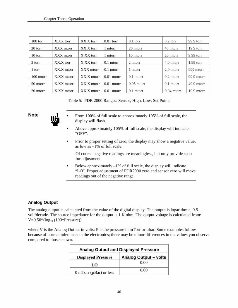
Reading PressurePressure display and ranging are automatic in the PDR 2000. Most readings will take place between zeropressure and the full scale of the PDR 2000. Table 5 that follows, will help explain the operation.
PDR 2000 Ranges: Sensor, High, Low, Set PointsSensorRangeFull-Scale
PDR 2000Lowest Scale
PDR 2000HighestScale
HighestResolution
LowestRecommendedReliable Value
Lowest SetPoint
HighestSet Point
1000 torr XX.X torr XXX torr 0.1 torr 1 torr 2 torr 999 torr
Chapter Three: Operation
40
100 torr X.XX torr XX.X torr 0.01 torr 0.1 torr 0.2 torr 99.9 torr
20 torr XXX mtorr XX.X torr 1 mtorr 20 mtorr 40 mtorr 19.9 torr
10 torr XXX mtorr X.XX torr 1 mtorr 10 mtorr 20 mtorr 9.99 torr
2 torr XX.X torr X.XX torr 0.1 mtorr 2 mtorr 4.0 mtorr 1.99 torr
1 torr XX.X mtorr XXX mtorr 0.1 mtorr 1 mtorr 2.0 mtorr 999 mtorr
100 mtorr X.XX mtorr XX.X mtorr 0.01 mtorr 0.1 mtorr 0.2 mtorr 99.9 mtorr
50 mtorr X.XX mtorr XX.X mtorr 0.01 mtorr 0.05 mtorr 0.1 mtorr 49.9 mtorr
20 mtorr X.XX mtorr XX.X mtorr 0.01 mtorr 0.1 mtorr 0.04 mtorr 19.9 mtorr
Table 5: PDR 2000 Ranges: Sensor, High, Low, Set Points
Note • From 100% of full scale to approximately 105% of full scale, thedisplay will flash.
• Above approximately 105% of full scale, the display will indicate“OFF”.
• Prior to proper setting of zero, the display may show a negative value,as low as –1% of full scale.
Of course negative readings are meaningless, but only provide spanfor adjustment.
• Below approximately –1% of full scale, the display will indicate“LO”. Proper adjustment of PDR2000 zero and sensor zero will movereadings out of the negative range.
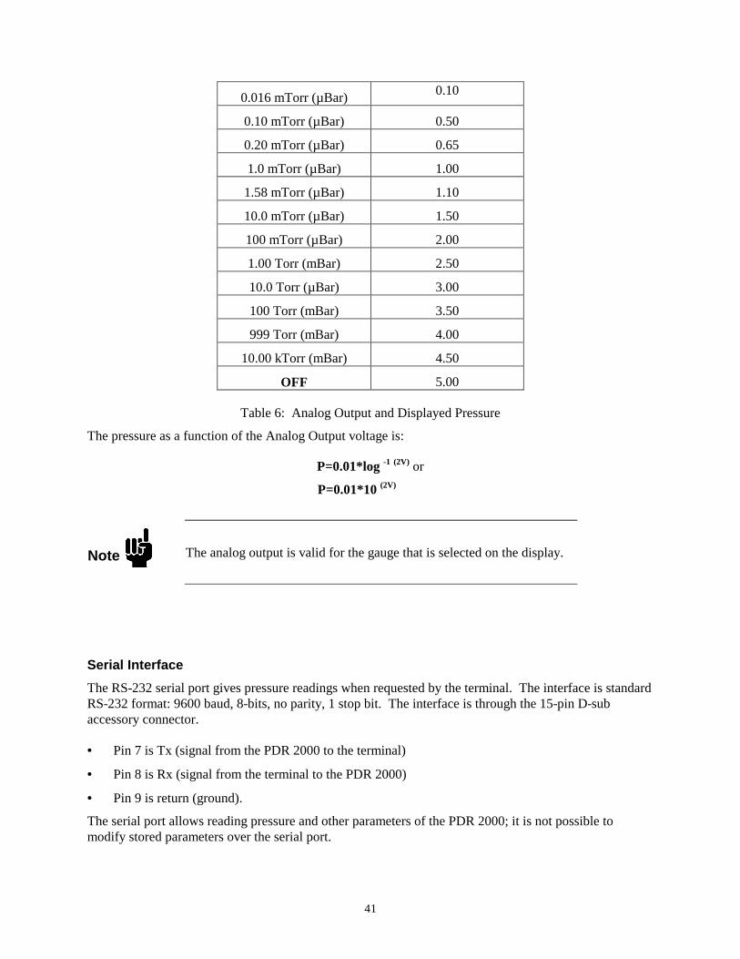
Analog OutputThe analog output is calculated from the value of the digital display. The output is logarithmic, 0.5volt/decade. The source impedance for the output is 1 K ohm. The output voltage is calculated from:V=0.50*(log10 (100*Pressure))
where V is the Analog Output in volts; P is the pressure in mTorr or µbar. Some examples followbecause of normal tolerances in the electronics; there may be minor differences in the values you observecompared to those shown.
Analog Output and Displayed PressureDisplayed Pressure Analog Output – volts
LO 0.00
0 mTorr (µBar) or less 0.00
41
0.016 mTorr (µBar) 0.10
0.10 mTorr (µBar) 0.50
0.20 mTorr (µBar) 0.65
1.0 mTorr (µBar) 1.00
1.58 mTorr (µBar) 1.10
10.0 mTorr (µBar) 1.50
100 mTorr (µBar) 2.00
1.00 Torr (mBar) 2.50
10.0 Torr (µBar) 3.00
100 Torr (mBar) 3.50
999 Torr (mBar) 4.00
10.00 kTorr (mBar) 4.50
OFF 5.00
Table 6: Analog Output and Displayed Pressure
The pressure as a function of the Analog Output voltage is:
P=0.01*log -1 (2V) or
P=0.01*10 (2V)
Note The analog output is valid for the gauge that is selected on the display.
Serial InterfaceThe RS-232 serial port gives pressure readings when requested by the terminal. The interface is standardRS-232 format: 9600 baud, 8-bits, no parity, 1 stop bit. The interface is through the 15-pin D-subaccessory connector.
• Pin 7 is Tx (signal from the PDR 2000 to the terminal)
• Pin 8 is Rx (signal from the terminal to the PDR 2000)
• Pin 9 is return (ground).
The serial port allows reading pressure and other parameters of the PDR 2000; it is not possible tomodify stored parameters over the serial port.
Description of Parameter Selection and Adjustment Chapter Three: Operation
42
The Commands Used in the PDR 2000:
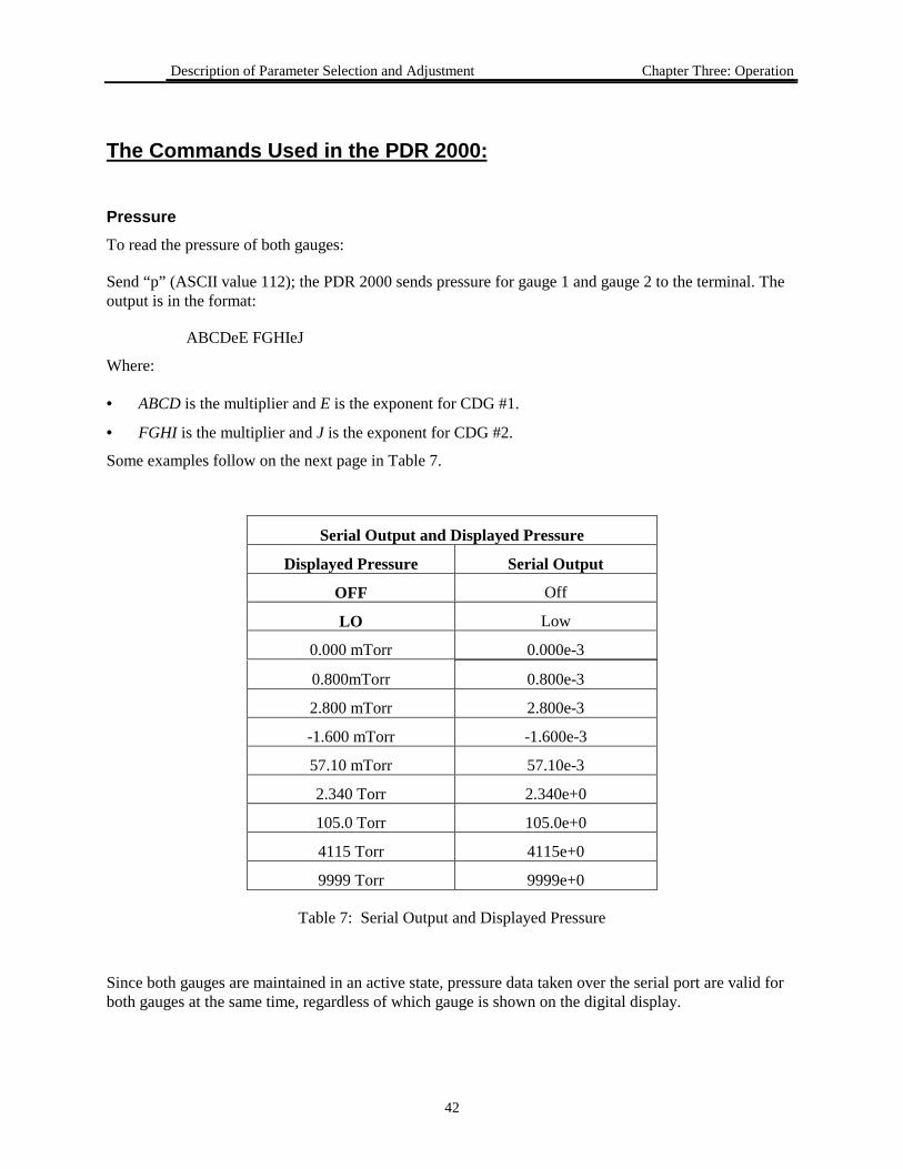
PressureTo read the pressure of both gauges:
Send “p” (ASCII value 112); the PDR 2000 sends pressure for gauge 1 and gauge 2 to the terminal. Theoutput is in the format:
ABCDeE FGHIeJ
Where:
• ABCD is the multiplier and E is the exponent for CDG #1.
• FGHI is the multiplier and J is the exponent for CDG #2.
Some examples follow on the next page in Table 7.
Serial Output and Displayed Pressure
Displayed Pressure Serial Output
OFF Off
LO Low
0.000 mTorr 0.000e-3
0.800mTorr 0.800e-3
2.800 mTorr 2.800e-3
-1.600 mTorr -1.600e-3
57.10 mTorr 57.10e-3
2.340 Torr 2.340e+0
105.0 Torr 105.0e+0
4115 Torr 4115e+0
9999 Torr 9999e+0
Table 7: Serial Output and Displayed Pressure
Since both gauges are maintained in an active state, pressure data taken over the serial port are valid forboth gauges at the same time, regardless of which gauge is shown on the digital display.
43
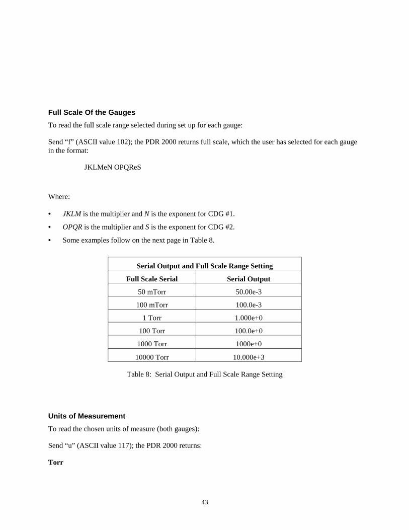
Full Scale Of the GaugesTo read the full scale range selected during set up for each gauge:
Send “f” (ASCII value 102); the PDR 2000 returns full scale, which the user has selected for each gaugein the format:
JKLMeN OPQReS
Where:
• JKLM is the multiplier and N is the exponent for CDG #1.
• OPQR is the multiplier and S is the exponent for CDG #2.
• Some examples follow on the next page in Table 8.
Serial Output and Full Scale Range Setting
Full Scale Serial Serial Output
50 mTorr 50.00e-3
100 mTorr 100.0e-3
1 Torr 1.000e+0
100 Torr 100.0e+0
1000 Torr 1000e+0
10000 Torr 10.000e+3
Table 8: Serial Output and Full Scale Range Setting
Units of MeasurementTo read the chosen units of measure (both gauges):
Send “u” (ASCII value 117); the PDR 2000 returns:
Torr
Chapter Three: Operation
44
or
mBar
or
Pascal
or
Arb
Set Point #1To read the setting and status of set point #1:
Send “1” (ASCII value 49); the PDR 2000 returns information for set point #1 in the format:
STUVeW XYZAeBCD
where:
• STUV is the multiplier and W is the exponent for set point #1 high
• XYZA is the multiplier and B is the exponent for set point #1 low
• C is set point relay status; 0= relay is not energized, 1=relay is energized.
• D is the gauge to which the set point #1 has been assigned: either 1 or 2
Set Point #2To read the setting and status of set point #2:
Send “2” (ASCII value 50); the PDR 2000 returns information for set point #2 in the same format as forset point #1, above.
Model and Software RevisionTo read the software identification:
Send “v” (ASCII value 118); the PDR 2000 returns the model number of the instrument and the revisionnumber, as in the following example 908A ver 1.10
Chapter Four: Maintenance and Troubleshooting
45
Changing Fuses
The controller contains two fuses. Both fuses are held in the fuse assembly that is part of the powermodule located on the back panel of the controller.
To change fuses, do the following:
1. Unplug the line cord from the power entry module at the rear of the PDR2000.
2. Locate the fuse block immediately below the line cord socket.
3. Press the tab of the fuse assembly and withdraw the fuse assembly from the power module.
4. Turn the fuse assembly around so that the fuses are facing you.
5. Check both fuses; replace the burnt-out fuse with a fuse of the appropriate rating (refer to ChapterOne for specifications information).
6. Reinsert the fuse assembly into the power module; push it in until the ears click into place.
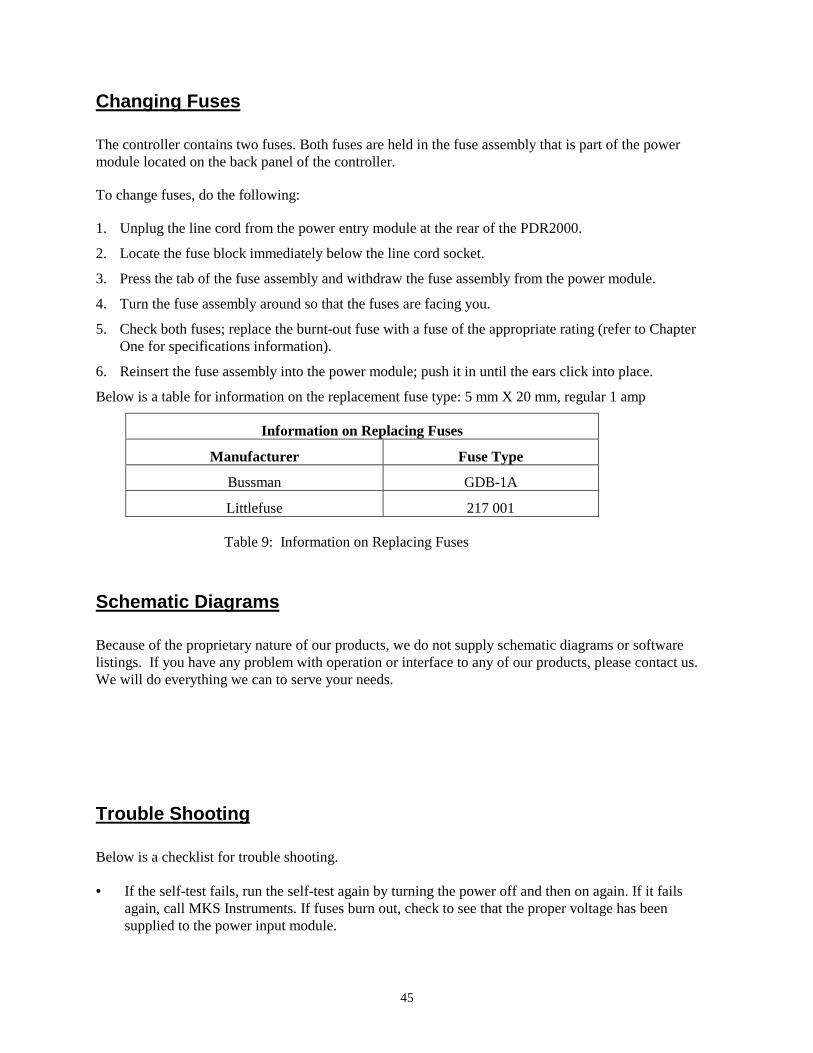
Below is a table for information on the replacement fuse type: 5 mm X 20 mm, regular 1 amp
Information on Replacing Fuses
Manufacturer Fuse Type
Bussman GDB-1A
Littlefuse 217 001
Table 9: Information on Replacing Fuses
Schematic Diagrams
Because of the proprietary nature of our products, we do not supply schematic diagrams or softwarelistings. If you have any problem with operation or interface to any of our products, please contact us.We will do everything we can to serve your needs.
Trouble Shooting
Below is a checklist for trouble shooting.
• If the self-test fails, run the self-test again by turning the power off and then on again. If it failsagain, call MKS Instruments. If fuses burn out, check to see that the proper voltage has beensupplied to the power input module.
46
• If fuses burn out repeatedly, call MKS Instruments.
• If the digital display consistently shows -LO or OFF, it may be that one of the internal power supplyprotection devices has removed power to the CDG. You may check this by measuring the voltage atthe connector or cable for the unaffected gauge. Since power for both gauges use the sameprotection device, either connector will show the power supply voltages. Normal range for thevoltages is 14.5 to 15.5 volts for both +15 volts and -15 volts. +15 may be measured on the red wire;-15 is on the green wire; power return is on the black wire. If the power supply protection has shutthe power off, you will typically measure less than 4 volts on the affected supply.
• If you verify that either power supply is shut off, remove power from the CDG for a few minutes toallow the protection device to reset itself. The protection device does not need to be replaced; it is areusable thermal fuse.
• You may wish to determine the cause for the loss of power supply voltage before applying poweragain. The PDR 2000 will protect itself if it finds excessive power draw again.
• It is normal for the PDR 2000 to feel warm to touch along the left side of the case. This is especiallytrue when operating heated CDGs because of the greater power they require.
•
Index
AAttaching the CDG Cable, 26Attaching the Power Cord, 30CChecking Supply Voltage, 30
Connecting the CDG, 26Controls and Indicators, 20DDescription of Parameter Selection and
Adjustment, 32

47
FFront Panel Controls, 31HHow To Unpack the PDR 2000 Controller, 25MMaking Accessory Connections, 29Manual organization, 23Mounting the Controller, 26
RReturning the product, 18SSafety procedures and precautions, 3–4Selecting the CDG, 26Sequence After Power Being Turned On, 31Specifications, 18