MKS PDR-C, 1C/2C Manual - MKS Instruments, Inc
52
110180-P1 Rev D, 12/97 MKS Type PDR-C-1C/2C Power Supply Digital Readout
Transcript of MKS PDR-C, 1C/2C Manual - MKS Instruments, Inc

110180-P1Rev D, 12/97
MKS Type PDR-C-1C/2CPower Supply
Digital Readout

Copyright © 1997 by MKS Instruments, Inc.
All rights reserved. No part of this work may be reproduced or transmitted in any form or byany means, electronic or mechanical, including photocopying and recording, or by anyinformation storage or retrieval system, except as may be expressly permitted in writing by MKSInstruments, Inc.
Baratron is a registered trademark of MKS Instruments, Inc., Andover, MA
Table of Contents
iii
Table of Contents
Safety Information.......................................................................................................................1
Symbols Used in This Instruction Manual.....................................................................1
Symbols Found on the Unit............................................................................................2
Safety Procedures and Precautions ................................................................................3
Sicherheitshinweise.....................................................................................................................5
In dieser Betriebsanleitung vorkommende Symbole .....................................................5
Am Gerät angebrachte Symbole ....................................................................................6
Sicherheitsvorschriften und Vorsichtsmaßnahmen........................................................7
Informations relatives à la sécurité .............................................................................................9
Symboles utilisés dans ce manuel d'utilisation ..............................................................9
Symboles apparaissant sur l'appareil..............................................................................10
Mesures de sécurité et mises en garde ...........................................................................11
Información sobre seguridad.......................................................................................................13
Símbolos usados en el manual de instrucciones ............................................................13
Símbolos que aparecen en la unidad ..............................................................................14
Procedimientos y precauciones de seguridad.................................................................15
Chapter One: General Information.............................................................................................17
Introduction ....................................................................................................................17
How This Manual is Organized......................................................................................18
Customer Support...........................................................................................................18
Chapter Two: Installation...........................................................................................................19
How To Unpack the Type PDR-C-1C/2C Unit..............................................................19
Unpacking Checklist .........................................................................................19
Product Location and Requirements ..............................................................................20
Operating Environmental Requirements...........................................................20
Dimensions.....................................................................................................................20
Setup...............................................................................................................................22
Grounds .............................................................................................................22

Table of Contents
iv
Chapter Three: Overview ...........................................................................................................23
Rear Panel Connections and Controls ............................................................................23
Pressure Sensor Connector................................................................................23
Decimal Point Selector......................................................................................23
Power Interface Connector................................................................................24
Interface Connector (J118)................................................................................24
BCD Output Connector .....................................................................................24
Set point Channel Select Switches ....................................................................24
Front Panel Controls and Indicators...............................................................................25
Power Switch.....................................................................................................25
Display (DVM)..................................................................................................25
Zero Adjust Control...........................................................................................25
Set Point Adjust Controls..................................................................................25
Read Set Point Switch .......................................................................................25
Set Point Relay Indicator Lamps.......................................................................25
Engineering Units Selection Switch..................................................................25
x10-3 Lamp.........................................................................................................25
Channel Select/Remote/Auto Switch ................................................................26
Interface Connector (J118) Pinout .................................................................................27
Pressure Sensor Terminal Block Connections ...............................................................28
Chapter Four: Theory of Operation............................................................................................29
Pressure Signal ...............................................................................................................29
Set Points........................................................................................................................29
Overrange Comparator ...................................................................................................29
Power Supply..................................................................................................................29
Pressure Level Comparators...........................................................................................30
Channel Selector / Function Switch ...............................................................................30
Chapter Five: Maintenance ........................................................................................................31
General Information .......................................................................................................31
Fault Isolation.................................................................................................................31
Power Supply ....................................................................................................32
Pressure Signal Amplification and Readout .....................................................32
Table of Contents
v
Set Point Circuits...............................................................................................35
Channel Selection Circuits ................................................................................35
Appendix A: Product Specifications ..........................................................................................37
Physical Specifications...................................................................................................37
Environmental Specifications ........................................................................................37
Electrical Specifications.................................................................................................37
Set Point Specifications..................................................................................................38
Appendix B: Model Code Explanation ......................................................................................39
Model Code ....................................................................................................................39
Appendix C: BCD Option ..........................................................................................................41
General Information .......................................................................................................41
Index............................................................................................................................................43

Table of Contents
vi
List of Figures and Tables
vii
List of Figures and Tables
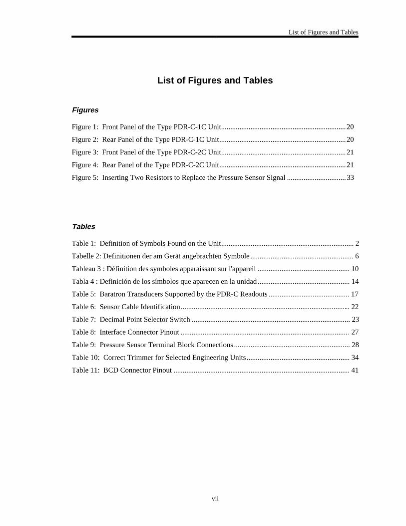
Figures
Figure 1: Front Panel of the Type PDR-C-1C Unit....................................................................20
Figure 2: Rear Panel of the Type PDR-C-1C Unit.....................................................................20
Figure 3: Front Panel of the Type PDR-C-2C Unit....................................................................21
Figure 4: Rear Panel of the Type PDR-C-2C Unit.....................................................................21
Figure 5: Inserting Two Resistors to Replace the Pressure Sensor Signal ................................33
Tables
Table 1: Definition of Symbols Found on the Unit........................................................................ 2
Tabelle 2: Definitionen der am Gerät angebrachten Symbole ........................................................ 6
Tableau 3 : Définition des symboles apparaissant sur l'appareil .................................................. 10
Tabla 4 : Definición de los símbolos que aparecen en la unidad.................................................. 14
Table 5: Baratron Transducers Supported by the PDR-C Readouts ............................................ 17
Table 6: Sensor Cable Identification............................................................................................ 22
Table 7: Decimal Point Selector Switch ...................................................................................... 23
Table 8: Interface Connector Pinout ............................................................................................ 27
Table 9: Pressure Sensor Terminal Block Connections............................................................... 28
Table 10: Correct Trimmer for Selected Engineering Units........................................................ 34
Table 11: BCD Connector Pinout ................................................................................................ 41

List of Figures and Tables
viii

Safety Information
1
Safety Information
Symbols Used in This Instruction Manual
Definitions of WARNING, CAUTION, and NOTE messages used throughout the manual.
Warning The WARNING sign denotes a hazard. It calls attention to aprocedure, practice, condition, or the like, which, if notcorrectly performed or adhered to, could result in injury topersonnel.
Caution The CAUTION sign denotes a hazard. It calls attention to anoperating procedure, practice, or the like, which, if not correctlyperformed or adhered to, could result in damage to or destruction ofall or part of the product.
Note The NOTE sign denotes important information. It calls attention to aprocedure, practice, condition, or the like, which is essential to highlight.
Safety Information
2
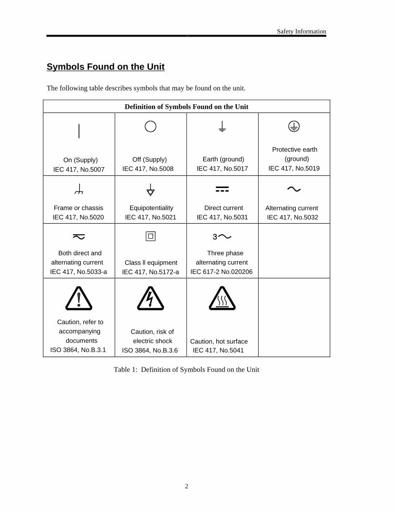
Symbols Found on the Unit
The following table describes symbols that may be found on the unit.
Definition of Symbols Found on the Unit
|
On (Supply) IEC 417, No.5007
Off (Supply)IEC 417, No.5008
Earth (ground) IEC 417, No.5017
Protective earth (ground)
IEC 417, No.5019
Frame or chassis IEC 417, No.5020
Equipotentiality IEC 417, No.5021
Direct current IEC 417, No.5031
Alternating currentIEC 417, No.5032
Both direct andalternating current
IEC 417, No.5033-aClass ll equipment
IEC 417, No.5172-a
Three phasealternating current
IEC 617-2 No.020206
Caution, refer toaccompanying
documentsISO 3864, No.B.3.1
Caution, risk ofelectric shock
ISO 3864, No.B.3.6Caution, hot surfaceIEC 417, No.5041
Table 1: Definition of Symbols Found on the Unit
Safety Information
3
Safety Procedures and Precautions
The following general safety precautions must be observed during all phases of operation of thisinstrument. Failure to comply with these precautions or with specific warnings elsewhere inthis manual violates safety standards of intended use of the instrument and may impair theprotection provided by the equipment. MKS Instruments, Inc. assumes no liability for thecustomer’s failure to comply with these requirements.
DO NOT SUBSTITUTE PARTS OR MODIFY INSTRUMENT
Do not install substitute parts or perform any unauthorized modification to the instrument.Return the instrument to an MKS Calibration and Service Center for service and repair to ensurethat all safety features are maintained.
SERVICE BY QUALIFIED PERSONNEL ONLY
Operating personnel must not remove instrument covers. Component replacement and internaladjustments must be made by qualified service personnel only.
GROUNDING THE PRODUCT
This product is grounded through the grounding conductor of the power cord. To avoidelectrical shock, plug the power cord into a properly wired receptacle before connecting it to theproduct input or output terminals. A protective ground connection by way of the groundingconductor in the power cord is essential for safe operation.
DANGER ARISING FROM LOSS OF GROUND
Upon loss of the protective-ground connection, all accessible conductive parts (including knobsand controls that may appear to be insulating) can render an electrical shock.
GROUND AND USE PROPER ELECTRICAL FITTINGS
Dangerous voltages are contained within this instrument. All electrical fittings and cables mustbe of the type specified, and in good condition. All electrical fittings must be properly connectedand grounded.
USE THE PROPER POWER CORD
Use only a power cord that is in good condition and which meets the input power requirementsspecified in the manual.
Use only a detachable cord set with conductors that have a cross-sectional area equal to orgreater than 0.75 mm2. The power cable should be approved by a qualified agency such as VDE,Semko, or SEV.

Safety Information
4
USE THE PROPER POWER SOURCE
This product is intended to operate from a power source that does not apply more voltagebetween the supply conductors, or between either of the supply conductors and ground, than thatspecified in the manual.
USE THE PROPER FUSE
Use only a fuse of the correct type, voltage rating, and current rating, as specified for yourproduct.
DO NOT OPERATE IN EXPLOSIVE ATMOSPHERES
To avoid explosion, do not operate this product in an explosive environment unless it has beenspecifically certified for such operation.
HIGH VOLTAGE DANGER
High voltage is present in the cable, and in the sensor when the controller is turned on.

Sicherheitshinweise
5
Sicherheitshinweise
In dieser Betriebsanleitung vorkommende Symbole
Definition der mit WARNUNG!, VORSICHT! und HINWEIS überschriebenen Abschnitte indieser Betriebsanleitung.
Warnung! Das Symbol WARNUNG! weist auf eine Gefahren quelle hin. Esmacht auf einen Arbeitsablauf, eine Arbeitsweise, einenZustand oder eine sonstige Gegebenheit aufmerksam, derenunsachgemäße Ausführung bzw. ungenügendeBerücksichtigung zu Körperverletzung führen kann.
Vorsicht! Das Symbol VORSICHT! weist auf eine Gefahrenquelle hin. Esmacht auf einen Bedienungsablauf, eine Arbeitsweise oder einesonstige Gegebenheit aufmerksam, deren unsachgemäße Ausführungbzw. Ungenügende Berücksichtigung zu einer Beschädigung oderZerstörung des Produkts oder von Teilen des Produkts führen kann.
Hinweis Das Symbol HINWEIS weist auf eine wichtige Mitteilung hin, die aufeinen Arbeitsablauf, eine Arbeitsweise, einen Zustand oder eine sonstigeGegebenheit von besonderer Wichtigkeit aufmerksam macht.
Sicherheitshinweise
6
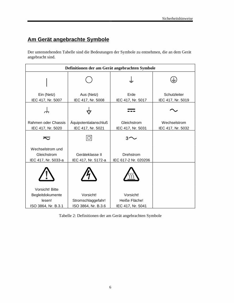
Am Gerät angebrachte Symbole
Der untenstehenden Tabelle sind die Bedeutungen der Symbole zu entnehmen, die an dem Gerätangebracht sind.
Definitionen der am Gerät angebrachten Symbole
|Ein (Netz)
IEC 417, Nr. 5007
Aus (Netz)
IEC 417, Nr. 5008
Erde
IEC 417, Nr. 5017
Schutzleiter
IEC 417, Nr. 5019
Rahmen oder Chassis
IEC 417, Nr. 5020
Äquipotentialanschluß
IEC 417, Nr. 5021
Gleichstrom
IEC 417, Nr. 5031
Wechselstrom
IEC 417, Nr. 5032
Wechselstrom und
Gleichstrom
IEC 417, Nr. 5033-a
Geräteklasse II
IEC 417, Nr. 5172-a
Drehstrom
IEC 617-2 Nr. 020206
Vorsicht! Bitte
Begleitdokumente
lesen!
ISO 3864, Nr. B.3.1
Vorsicht!
Stromschlaggefahr!
ISO 3864, Nr. B.3.6
Vorsicht!
Heiße Fläche!
IEC 417, Nr. 5041
Tabelle 2: Definitionen der am Gerät angebrachten Symbole

Sicherheitshinweise
7
Sicherheitsvorschriften und Vorsichtsmaßnahmen
Die untenstehenden allgemeinen Sicherheitsvorschriften sind bei allen Betriebs-phasendieses Instruments zu befolgen. Jede Mißachtung dieser Sicherheits-vorschriften odersonstiger spezifischer Warnhinweise in dieser Betriebsanleitung stellt eineZuwiderhandlung der für dieses Instrument geltenden Sicherheits-standards dar und kanndie an diesem Instrument vorgesehenen Schutzvor-richtungen unwirksam machen. MKSInstruments, Inc. haftet nicht für eine Mißachtung dieser Sicherheitsvorschriften seitensdes Kunden.
Keine Teile austauschen und keine Veränderungen vornehmen!
Bauen Sie in das Instrument keine Ersatzteile ein, und nehmen Sie keine eigenmächtigenÄnderungen am Gerät vor! Schicken Sie das Instrument zu Wartungs- und Reparatur-zweckenan einen MKS-Kalibrierungs- und -Kundendienst ein! Dadurch wird sicher-gestellt, daß alleSicherheitseinrichtungen voll funktionsfähig bleiben.
Wartung nur durch qualifizierte Fachleute!
Das Gehäuse des Instruments darf vom Bedienpersonal nicht geöffnet werden. Das Auswechselnvon Bauteilen und das Vornehmen von internen Einstellungen ist nur von qualifiziertenFachleuten durchzuführen.
Produkt erden!
Dieses Produkt ist mit einer Erdleitung und einem Schutzkontakt am Netzstecker versehen. Umder Gefahr eines elektrischen Schlages vorzubeugen, ist das Netzkabel an einer vorschriftsmäßiggeerdeten Schutzkontaktsteckdose anzuschließen, bevor es an den Eingangs- bzw.Ausgangsklemmen des Produkts angeschlossen wird. Das Instrument kann nur sicher betriebenwerden, wenn es über den Erdleiter des Netzkabels und einen Schutzkontakt geerdet wird.
Gefährdung durch Verlust der Schutzerdung!
Geht die Verbindung zum Schutzleiter verloren, besteht an sämtlichen zugänglichen Teilen ausstromleitendem Material die Gefahr eines elektrischen Schlages. Dies gilt auch für Knöpfe undandere Bedienelemente, die dem Anschein nach isoliert sind.
Sicherheitshinweise
8
Erdung und Verwendung geeigneter elektrischer Armaturen!
In diesem Instrument liegen gefährliche Spannungen an. Alle verwendeten elektrischenArmaturen und Kabel müssen dem angegebenen Typ entsprechen und sich in einwand-freiemZustand befinden. Alle elektrischen Armaturen sind vorschriftsmäßig anzubringen und zu erden.
Richtiges Netzkabel verwenden!
Das verwendete Netzkabel muß sich in einwandfreiem Zustand befinden und den in derBetriebsanleitung enthaltenen Anschlußwerten entsprechen.
Das Netzkabel muß abnehmbar sein. Der Querschnitt der einzelnen Leiter darf nicht weniger als0,75 mm2 betragen. Das Netzkabel sollte einen Prüfvermerk einer zuständigen Prüfstelle tragen,z.B. VDE, Semko oder SEV.
Richtige Stromquelle verwenden!
Dieses Produkt ist für eine Stromquelle vorgesehen, bei der die zwischen den Leitern bzw.zwischen jedem der Leiter und dem Masseleiter anliegende Spannung den in dieserBetriebsanleitung angegebenen Wert nicht überschreitet.
Richtige Sicherung benutzen!
Es ist eine Sicherung zu verwenden, deren Typ, Nennspannung und Nennstromstärke denAngaben für dieses Produkt entsprechen.
Gerät nicht in explosiver Atmosphäre benutzen!
Um der Gefahr einer Explosion vorzubeugen, darf dieses Gerät nicht in der Nähe explosiverStoffe eingesetzt werden, sofern es nicht ausdrücklich für diesen Zweck zertifiziert worden ist.
Hochspannungsgefahr!
Bei eingeschaltetem Steuerteil liegt im Kabel und im Sensor Hochspannung an.
Informations relatives à la sécurité
9
Informations relatives à la sécurité
Symboles utilisés dans ce manuel d'utilisation
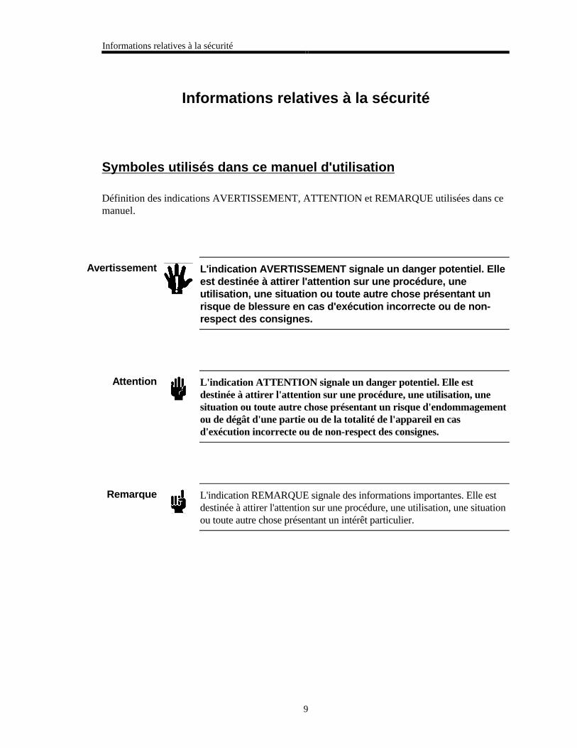
Définition des indications AVERTISSEMENT, ATTENTION et REMARQUE utilisées dans cemanuel.
Avertissement L'indication AVERTISSEMENT signale un danger potentiel. Elleest destinée à attirer l'attention sur une procédure, uneutilisation, une situation ou toute autre chose présentant unrisque de blessure en cas d'exécution incorrecte ou de non-respect des consignes.
Attention L'indication ATTENTION signale un danger potentiel. Elle estdestinée à attirer l'attention sur une procédure, une utilisation, unesituation ou toute autre chose présentant un risque d'endommagementou de dégât d'une partie ou de la totalité de l'appareil en casd'exécution incorrecte ou de non-respect des consignes.
Remarque L'indication REMARQUE signale des informations importantes. Elle estdestinée à attirer l'attention sur une procédure, une utilisation, une situationou toute autre chose présentant un intérêt particulier.
Informations relatives à la sécurité
10
Symboles apparaissant sur l'appareil
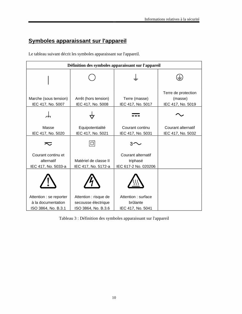
Le tableau suivant décrit les symboles apparaissant sur l'appareil.
Définition des symboles apparaissant sur l'appareil
|
Marche (sous tension)
IEC 417, No. 5007
Arrêt (hors tension)
IEC 417, No. 5008
Terre (masse)
IEC 417, No. 5017
Terre de protection
(masse)
IEC 417, No. 5019
Masse
IEC 417, No. 5020
Equipotentialité
IEC 417, No. 5021
Courant continu
IEC 417, No. 5031
Courant alternatif
IEC 417, No. 5032
Courant continu et
alternatif
IEC 417, No. 5033-a
Matériel de classe II
IEC 417, No. 5172-a
Courant alternatif
triphasé
IEC 617-2 No. 020206
Attention : se reporter
à la documentation
ISO 3864, No. B.3.1
Attention : risque de
secousse électrique
ISO 3864, No. B.3.6
Attention : surface
brûlante
IEC 417, No. 5041
Tableau 3 : Définition des symboles apparaissant sur l'appareil
Informations relatives à la sécurité
11
Mesures de sécurité et mises en garde
Prendre toutes les précautions générales suivantes pendant toutes les phases d'utilisation decet appareil. Le non-respect de ces précautions ou des avertissements contenus dans cemanuel entraîne une violation des normes de sécurité relatives à l'utilisation de l'appareil et lerisque de réduire le niveau de protection fourni par l'appareil. MKS Instruments, Inc. neprend aucune responsabilité pour les conséquences de tout non-respect des consignes de lapart de ses clients.
NE PAS SUBSTITUER DES PIÈCES OU MODIFIER L'APPAREIL
Ne pas utiliser de pièces détachées autres que celles vendues par MKS Instruments, Inc. oumodifier l'appareil sans l'autorisation préalable de MKS Instruments, Inc. Renvoyer l'appareil àun centre d'étalonnage et de dépannage MKS pour tout dépannage ou réparation afin de s'assurerque tous les dispositifs de sécurité sont maintenus.
DÉPANNAGE EFFECTUÉ UNIQUEMENT PAR UN PERSONNEL QUALIFIÉ
L'opérateur de l'appareil ne doit pas enlever le capot de l'appareil. Le remplacement descomposants et les réglages internes doivent être effectués uniquement par un personneld'entretien qualifié.
MISE À LA TERRE DE L'APPAREIL
Cet appareil est mis à la terre à l'aide du fil de terre du cordon d'alimentation. Pour éviter toutrisque de secousse électrique, brancher le cordon d'alimentation sur une prise de courantcorrectement câblée avant de le brancher sur les bornes d'entrée ou de sortie de l'appareil. Unemise à la terre de protection à l'aide du fil de terre du cordon d'alimentation est indispensablepour une utilisation sans danger de l'appareil.
DANGER LIÉ À UN DÉFAUT DE TERRE
En cas de défaut de terre, toutes les pièces conductrices accessibles (y compris les boutons decommande ou de réglage qui semblent être isolés) peuvent être source d'une secousse électrique.
MISE À LA TERRE ET UTILISATION CORRECTE D'ACCESSOIRES ÉLECTRIQUES
Des tensions dangereuses existent à l'intérieur de l'appareil. Tous les accessoires et les câblesélectriques doivent être conformes au type spécifié et être en bon état. Tous les accessoiresélectriques doivent être correctement connectés et mis à la terre.
Informations relatives à la sécurité
12
UTILISATION D'UN CORDON D'ALIMENTATION APPROPRIÉ
Utiliser uniquement un cordon d'alimentation en bon état et conforme aux exigences depuissance d'entrée spécifiées dans le manuel.
Utiliser uniquement un cordon d'alimentation amovible avec des conducteurs dont la section estégale ou supérieure à 0,75 mm2. Le cordon d'alimentation doit être approuvé par un organismecompétent tel que VDE, Semko ou SEV.
UTILISATION D'UNE ALIMENTATION APPROPRIÉE
Cet appareil est conçu pour fonctionner en s'alimentant sur une source de courant électriquen'appliquant pas une tension entre les conducteurs d'alimentation, ou entre les conducteursd'alimentation et le conducteur de terre, supérieure à celle spécifiée dans le manuel.
UTILISATION D'UN FUSIBLE APPROPRIÉ
Utiliser uniquement un fusible conforme au type, à la tension nominale et au courant nominalspécifiés pour l'appareil.
NE PAS UTILISER DANS UNE ATMOSPHÈRE EXPLOSIVE
Pour éviter tout risque d'explosion, ne pas utiliser l'appareil dans une atmosphère explosive àmoins qu'il n'ait été approuvé pour une telle utilisation.
DANGER DE HAUTE TENSION
Une haute tension est présente dans le câble et dans le capteur lorsque le contrôleur est soustension.
Información sobre seguridad
13
Información sobre seguridad
Símbolos usados en el manual de instrucciones
Definiciones de los mensajes de ADVERTENCIA, PRECAUCIÓN Y OBSERVACIÓN usadosen el manual.
Advertencia El símbolo de ADVERTENCIA indica un riesgo. Pone derelieve un procedimiento, práctica, condición, etc., que, de norealizarse u observarse correctamente, podría causar lesionesa los empleados.
Precaución El símbolo de PRECAUCIÓN indica un riesgo. Pone de relieve unprocedimiento, práctica, etc., de tipo operativo que, de no realizarseu observarse correctamente, podría causar desperfectos alinstrumento, o llegar incluso a causar su destrucción total o parcial.
Observación El símbolo de OBSERVACIÓN indica información de importancia. Ponede relieve un procedimiento, práctica, condición, etc., cuyo conocimientoresulta esencial.
Información sobre seguridad
14
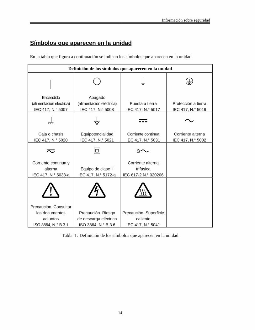
Símbolos que aparecen en la unidad
En la tabla que figura a continuación se indican los símbolos que aparecen en la unidad.
Definición de los símbolos que aparecen en la unidad
|Encendido
(alimentación eléctrica)
IEC 417, N.° 5007
Apagado
(alimentación eléctrica)
IEC 417, N.° 5008
Puesta a tierra
IEC 417, N.° 5017
Protección a tierra
IEC 417, N.° 5019
Caja o chasis
IEC 417, N.° 5020
Equipotencialidad
IEC 417, N.° 5021
Corriente continua
IEC 417, N.° 5031
Corriente alterna
IEC 417, N.° 5032
Corriente continua y
alterna
IEC 417, N.° 5033-a
Equipo de clase II
IEC 417, N.° 5172-a
Corriente alterna
trifásica
IEC 617-2 N.° 020206
Precaución. Consultar
los documentos
adjuntos
ISO 3864, N.° B.3.1
Precaución. Riesgo
de descarga eléctrica
ISO 3864, N.° B.3.6
Precaución. Superficie
caliente
IEC 417, N.° 5041
Tabla 4 : Definición de los símbolos que aparecen en la unidad
Información sobre seguridad
15
Procedimientos y precauciones de seguridad
Las precauciones generales de seguridad que figuran a continuación deben observarsedurante todas las fases de funcionamiento del presente instrumento. La no observancia dedichas precauciones, o de las advertencias específicas a las que se hace referencia en elmanual, contraviene las normas de seguridad referentes al uso previsto del instrumento ypodría impedir la protección que proporciona el instrumento. MKS Instruments, Inc., noasume responsabilidad alguna en caso de que el cliente haga caso omiso de estosrequerimientos.
NO UTILIZAR PIEZAS NO ORIGINALES NI MODIFICAR EL INSTRUMENTO
No se debe instalar piezas que no sean originales ni modificar el instrumento sin autorización.Para garantizar que las prestaciones de seguridad se observen en todo momento, enviar elinstrumento al Centro de servicio y calibración de MKS cuando sea necesaria su reparación yservicio de mantenimiento.
REPARACIONES EFECTUADAS ÚNICAMENTE POR TÉCNICOS ESPECIALIZADOS
Los operarios no deben retirar las cubiertas del instrumento. El cambio de piezas y los reajustesinternos deben efectuarlos únicamente técnicos especializados.
PUESTA A TIERRA DEL INSTRUMENTO
Este instrumento está puesto a tierra por medio del conductor de tierra del cable eléctrico. Paraevitar descargas eléctricas, enchufar el cable eléctrico en una toma debidamente instalada, antesde conectarlo a las terminales de entrada o salida del instrumento. Para garantizar el uso sinriesgos del instrumento resulta esencial que se encuentre puesto a tierra por medio del conductorde tierra del cable eléctrico.
PELIGRO POR PÉRDIDA DE LA PUESTA A TIERRA
Si se pierde la conexión protectora de puesta a tierra, todas las piezas conductoras a las que setiene acceso (incluidos los botones y mandos que pudieran parecer estar aislados) podríanproducir descargar eléctricas.
PUESTA A TIERRA Y USO DE ACCESORIOS ELÉCTRICOS ADECUADOS
Este instrumento funciona con voltajes peligrosos. Todos los accesorios y cables eléctricos debenser del tipo especificado y mantenerse en buenas condiciones. Todos los accesorios eléctricosdeben estar conectados y puestos a tierra del modo adecuado.

Información sobre seguridad
16
USAR EL CABLE ELÉCTRICO ADECUADO
Usar únicamente un cable eléctrico que se encuentre en buenas condiciones y que cumpla losrequisitos de alimentación de entrada indicados en el manual.
Usar únicamente un cable desmontable instalado con conductores que tengan un área de seccióntransversal equivalente o superior a 0,75mm². El cable eléctrico debe estar aprobado por unaentidad autorizada como, por ejemplo, VDE, Semko o SEV.
USAR LA FUENTE DE ALIMENTACIÓN ELÉCTRICA ADECUADA
Este instrumento debe funcionar a partir de una fuente de alimentación eléctrica que no apliquemás voltaje entre los conductores de suministro, o entre uno de los conductores de suministro yla puesta a tierra, que el que se especifica en el manual.
USAR EL FUSIBLE ADECUADO
Usar únicamente un fusible del tipo, clase de voltaje y de corriente adecuados, según lo que seespecifica para el instrumento.
EVITAR SU USO EN ENTORNOS EXPLOSIVOS
Para evitar el riesgo de explosión, no usar este instrumento o en un entorno explosivo, a no serque haya sido certificado para tal uso.
PELIGRO POR ALTO VOLTAJE
Cuando el controlador está encendido, se registra alto voltaje en el cable y en el sensor.

Chapter One: General Information Introduction
17
Chapter One: General Information
Introduction
The MKS Type PDR-C-1C and PDR-C-2C are power supply and digital readouts which arepackaged in standard half-rack mount units. The PDR-C-2C is designed to provide power for,and accept the outputs from two pressure sensors. The PDR-C-1C is identical to the -2C exceptthe -1C is designed for operation with one pressure sensor.
The power supply for both the -1C and -2C is capable of providing ±15 VDC at up to 600 mA.This will provide enough power for two MKS Baratrons, including those listed in Table 5, or forany electronic manometer with similar input requirements.
Baratron Transducers Supported by the PDR-C Readouts
121 223 624
122 224 625
124 422 626
127 427 627
128 622 628 (only one)
221 623 722
Table 5: Baratron Transducers Supported by the PDR-C Readouts
The unit contains two set point-operated, single pole relays which may be controlled by eitherpressure channel in the -2C. Set point adjustment is accomplished by front panel COARSE andFINE controls which cover the entire range of the gauge in use. The relays’ status is indicated byfront panel lamps. “Failsafe” relay operation is standard, that is, the relays are not energized atpressures higher than the set point settings. The relays can be latched in the energized state bymeans of an external logic line to the rear panel Interface connector.
The readout is a 4½ place digital panel meter which indicates the output of the attached pressuresensor(s). Engineering units for the readout (mmHg, psi, kPa, mbar, inHg, inH2O, cmH2O) can beselected by a front panel switch. The meter also reads the current set point values in the sameengineering units by means of another front panel switch. The PDR-C-2C has an additional frontpanel switch which is used to select display of channel 1, display of channel 2, remote channelselection, or automatic channel selection. In automatic channel selection, the PDR-C-2C willdisplay Channel 1 sensor as long as it is less than 100%. If Channel 1 is greater than 100%,Channel 2 will be displayed.

How This Manual is Organized Chapter One: General Information
18
How This Manual is Organized
This manual is designed to provide instructions on how to set up, install, and operate a TypePDR-C-1C/2C unit.
Before installing your Type PDR-C-1C/2C unit in a system and/or operating it, carefullyread and familiarize yourself with all precautionary notes in the Safety Messages andProcedures section at the front of this manual. In addition, observe and obey all WARNING
and CAUTION notes provided throughout the manual.
Chapter One, General Information, (this chapter) introduces the product and describes theorganization of the manual.
Chapter Two, Installation, explains the environmental requirements and describes how to mountthe instrument in your system.
Chapter Three, Overview, gives a brief description of the instrument and its functionality.
Chapter Four, Operation, describes how to use the instrument and explains all the functions andfeatures.
Chapter Five, Maintenance, lists any maintenance required to keep the instrument in goodworking condition.
Chapter Six, Troubleshooting, provides a checklist for reference should the instrumentmalfunction.
Appendix A, Product Specifications, lists the specifications of the instrument.
Appendix B, Model Code Explanation, describes the model code.
Customer Support
Standard maintenance and repair services are available at all of our regional MKS Calibrationand Service Centers, listed on the back cover. In addition, MKS accepts the instruments of othermanufacturers for recalibration using the Primary and Transfer Standard calibration equipmentlocated at all of our regional service centers. Should any difficulties arise in the use of yourType PDR-C-1C/2C instrument, or to obtain information about companion products MKS offers,contact any authorized MKS Calibration and Service Center. If it is necessary to return theinstrument to MKS, please obtain an ERA Number (Equipment Return Authorization Number)from the MKS Calibration and Service Center before shipping. The ERA Number expediteshandling and ensures proper servicing of your instrument.
Please refer to the inside of the back cover of this manual for a list of MKS Calibration andService Centers.
Warning All returns to MKS Instruments must be free of harmful,corrosive, radioactive, or toxic materials.

Chapter Two: Installation How To Unpack the Type PDR-C-1C/2C Unit
19
Chapter Two: Installation
How To Unpack the Type PDR-C-1C/2C Unit
MKS has carefully packed the Type PDR-C-1C/2C unit so that it will reach you in perfectoperating order. Upon receiving the unit, however, you should check for defects, cracks, brokenconnectors, etc., to be certain that damage has not occurred during shipment.
Note Do not discard any packing materials until you have completed yourinspection and are sure the unit arrived safely.
If you find any damage, notify your carrier and MKS immediately. If it is necessary to return theunit to MKS, obtain an ERA Number (Equipment Return Authorization Number) from the MKSService Center before shipping. Please refer to the inside of the back cover of this manual for alist of MKS Calibration and Service Centers.
Caution Only qualified individuals should perform the installation and anyuser adjustments. They must comply with all the necessary ESD andhandling precautions while installing and adjusting the instrument.Proper handling is essential when working with all highly sensitiveprecision electronic instruments.
Unpacking Checklist
Standard Equipment:
• Type PDR-C-1C/2C Unit
• Type PDR-C-1C/2C Instruction Manual (this book)
Optional Equipment:
• Electrical Connector Accessories Kit - PDR-C-1C-K1 or PDR-C-2C-K1
• Interface cables
Product Location and Requirements Chapter Two: Installation
20
Product Location and Requirements
Operating Environmental Requirements
• Ambient Operating Temperature: 0° C to 50° C
• Ventilation requirements include sufficient air circulation
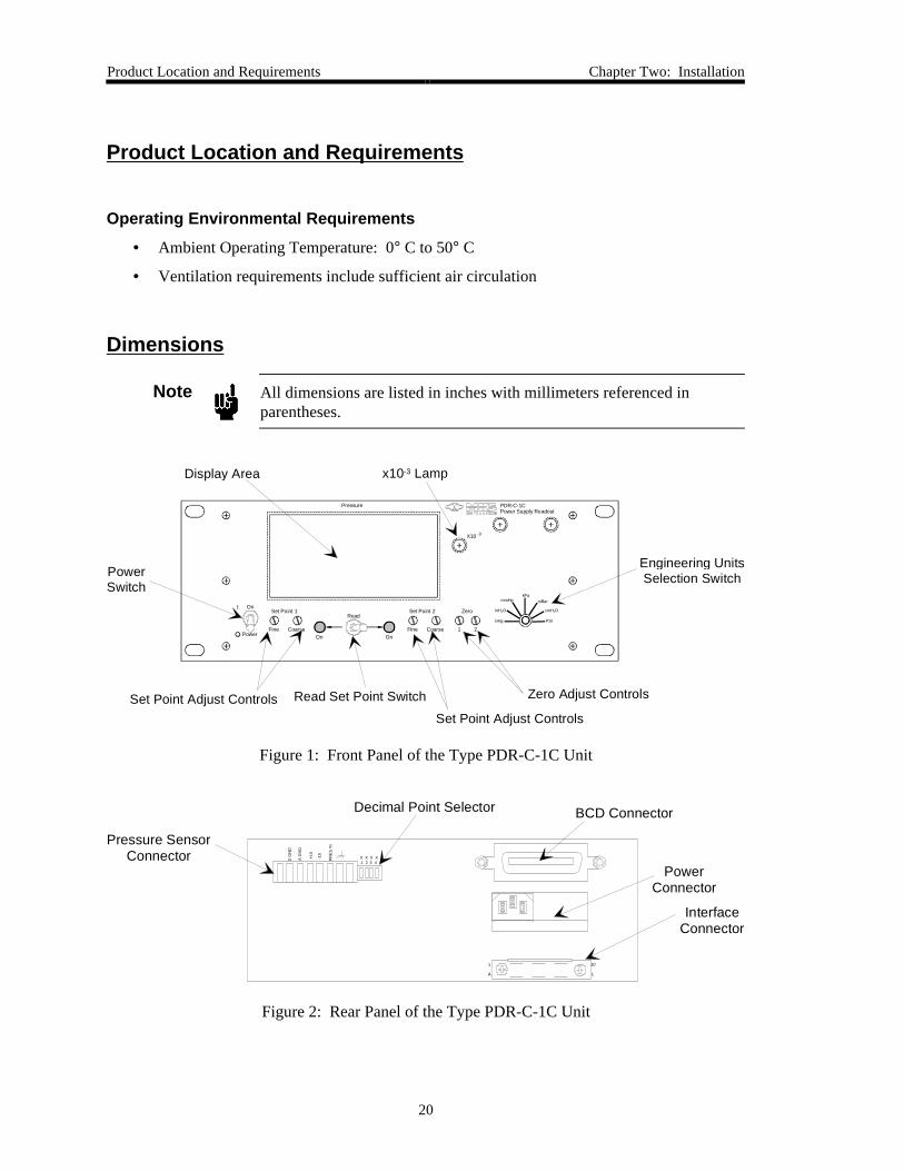
Dimensions
Note All dimensions are listed in inches with millimeters referenced inparentheses.
1 2
Zero
PDR-C-1C Power Supply Readout
CoarseFineOn
Set Point 1
OnCoarseFine
Set Point 2On
Power
kPa
inHg
-3X10
mBar
Pressure
Read
Display Area
PowerSwitch
Zero Adjust ControlsSet Point Adjust Controls
Set Point Adjust Controls
Read Set Point Switch
Engineering UnitsSelection Switch
x10-3 Lamp
inH2O
mmHg
cmH2O
PSI
Figure 1: Front Panel of the Type PDR-C-1C Unit
1
A
10
L
D G
ND
A G
ND
+15
-15
PR
ES
IN
X X X X 1 2 3 4
Pressure SensorConnector
Decimal Point Selector BCD Connector
PowerConnector
Interface Connector
Figure 2: Rear Panel of the Type PDR-C-1C Unit
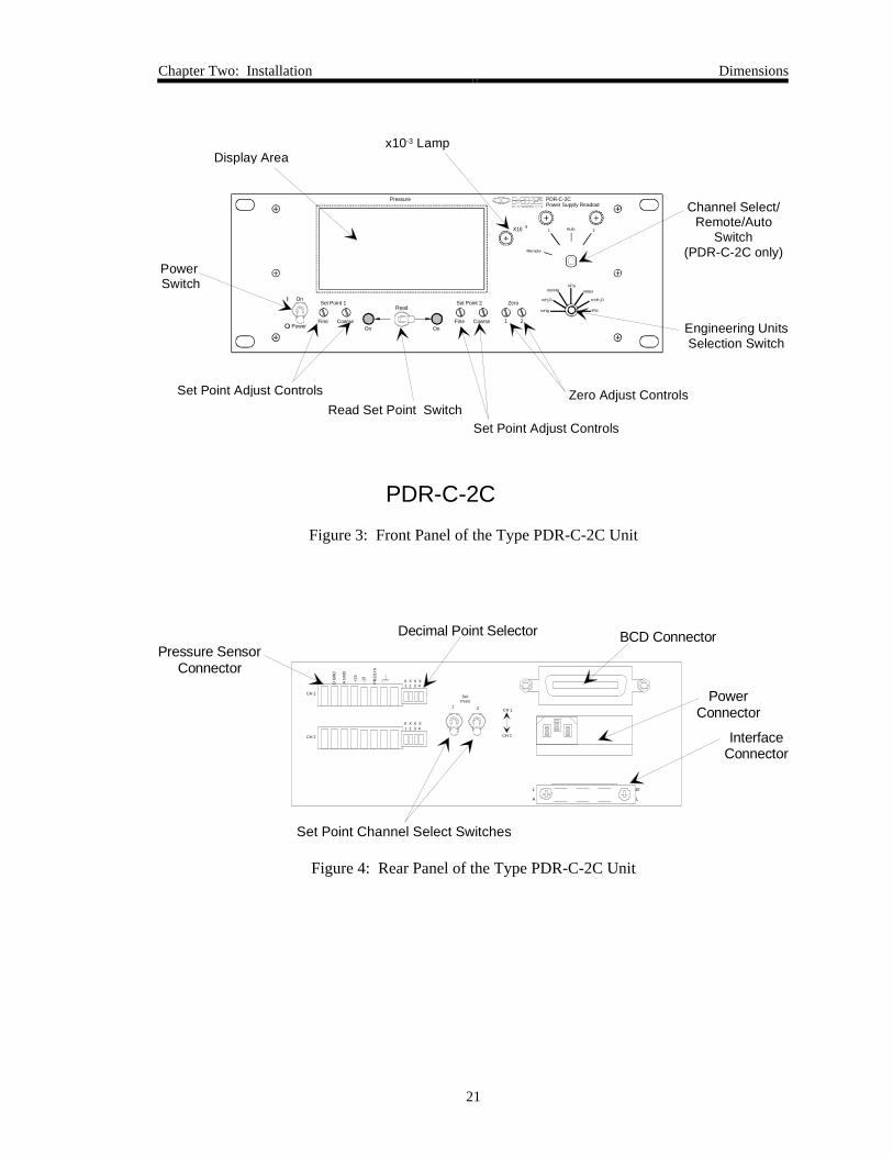
Chapter Two: Installation Dimensions
21
Auto
1 2
Zero
Remote
1 2
PDR-C-2C Power Supply Readout
CoarseFineOn
Set Point 1
OnCoarseFine
Set Point 2On
Power
-3X10
Pressure
Read
Display Area
Power Switch
Zero Adjust ControlsSet Point Adjust Controls
Set Point Adjust ControlsRead Set Point Switch
Engineering UnitsSelection Switch
Channel Select/Remote/Auto
Switch (PDR-C-2C only)
x10-3 Lamp
PDR-C-2C
kPa
inHg
mBar
inH2O
mmHg
cmH2O
PSI
Figure 3: Front Panel of the Type PDR-C-2C Unit
1
A
10
L
D G
ND
A G
ND
+15
-15
PR
ES
IN
X X X X 1 2 3 4
Pressure SensorConnector
Decimal Point Selector BCD Connector
PowerConnector
Interface Connector
X X X X 1 2 3 4
CH 1
CH 2
Set Point
1 2 CH 1
CH 2
Set Point Channel Select Switches
Figure 4: Rear Panel of the Type PDR-C-2C Unit
Setup Chapter Two: Installation
22
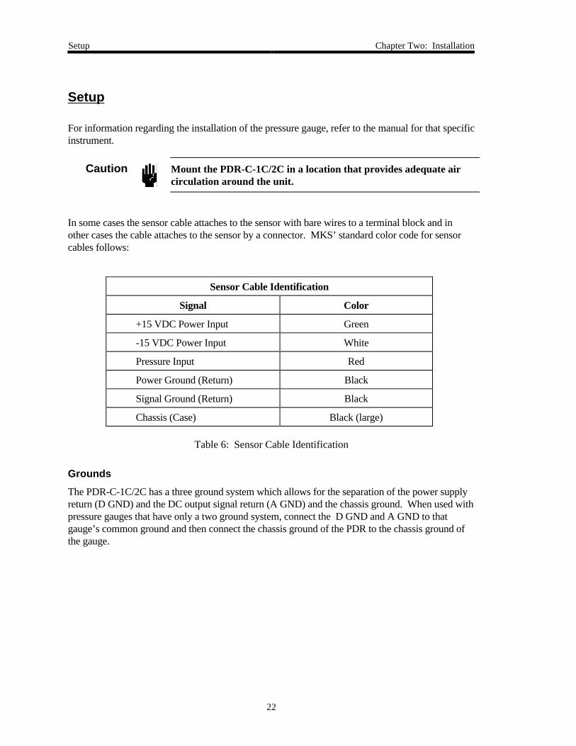
Setup
For information regarding the installation of the pressure gauge, refer to the manual for that specificinstrument.
Caution Mount the PDR-C-1C/2C in a location that provides adequate aircirculation around the unit.
In some cases the sensor cable attaches to the sensor with bare wires to a terminal block and inother cases the cable attaches to the sensor by a connector. MKS’ standard color code for sensorcables follows:
Sensor Cable Identification
Signal Color
+15 VDC Power Input Green
-15 VDC Power Input White
Pressure Input Red
Power Ground (Return) Black
Signal Ground (Return) Black
Chassis (Case) Black (large)
Table 6: Sensor Cable Identification
Grounds
The PDR-C-1C/2C has a three ground system which allows for the separation of the power supplyreturn (D GND) and the DC output signal return (A GND) and the chassis ground. When used withpressure gauges that have only a two ground system, connect the D GND and A GND to thatgauge’s common ground and then connect the chassis ground of the PDR to the chassis ground ofthe gauge.

Chapter Three: Overview Rear Panel Connections and Controls
23
Chapter Three: Overview
Rear Panel Connections and Controls
Pressure Sensor Connector
These connectors are used to interface the PDR with the pressure gauge(s). They provide powerto gauges requiring it, and receive the pressure signal back from the gauge. Refer to Table 9,page 28, for the connections.
Decimal Point Selector
These are 4PST rocker switches used to set the display decimal point to the appropriate position forthe pressure range being measured. The following chart shows switch settings for various full scalepressure values.
Decimal Point Selector Switch
Gauge F.S. Switch Selection
1 2 3 4
1 MM ON OFF OFF OFF
10 MM OFF ON OFF OFF
100 MM OFF OFF ON OFF
1000 MM OFF OFF OFF ON
10000 MM OFF OFF OFF OFF
Table 7: Decimal Point Selector Switch
Note Closing more than one switch (per channel) will produce multiple decimalpoints and cause interaction between channels.
Rear Panel Connections and Controls Chapter Three: Overview
24
Power Interface Connector
This module accepts a standard power cord, and contains a line fuse, filter, and input voltageselector. The selected line voltage is visible on a small PC board mounted behind the plasticwindow. To change this voltage proceed as follows:
1. Remove the line cord and slide the plastic window to the left.
2. Pull the fuse lever outward to eject the fuse.
3. Insert a small probe in the hole in the PC card and remove the card.
4. Position the PC board so that the voltage desired is readable from the rear.
5. Plug the card back into the module.
6. Insert the proper value fuse (1 ASB @ 120 VAC or ½ ASB @ 240 VAC).
7. Slide the window to the right.
8. Plug in the line cord.
Interface Connector (J118)
This 20 pin connector is used for external access to the PDR. Refer to Interface Connector(J118), page 27, for the pinout of the connector. Set point relay connections (NC, NO,COMMON) are available on the connector as well as 0 to 10 Volt full scale analog outputswhich are equal to the incoming pressure signal including zero correction. Also available on thisconnector are the LATCH control lines used to remotely hold the set point relays in theenergized state, and a 0 to 1 Volt analog output voltage line whose voltage is equal to the frontpanel display DVM input voltage. Analog and digital grounds are also brought out. ThePDR-C-2C uses three additional lines; two for identification of which channel is currently beingdisplayed and one line for remote selection of which channel is to be displayed.
BCD Output Connector
Optional Feature
This connector provides 5 Volt BCD logic lines directly from the front panel DVM. It is usedfor remote pressure reading and it outputs the same quantity as shown on the DVM. The BCDlines are updated approximately every 0.5 seconds, as is the display.
Set point Channel Select Switches
PDR-C-2C only
These switches are used to select which pressure signal is applied to each of the two set pointcomparators.

Chapter Three: Overview Front Panel Controls and Indicators
25
Front Panel Controls and Indicators
Power Switch
In the “On” position, the power switch applies power to the PDR unit.
Display (DVM)
The 4½ place voltmeter accepts 1.9999 Volts full scale. This meter contains its own power supply,and provides display information in BCD form to the rear panel. Decimal point information for thedisplay is obtained from rear panel range rocker switches and internal decoding circuits used inconjunction with the engineering units switch.
Zero Adjust Control
These controls are used as fine zero adjustments for the pressure gauge. An absolute pressuregauge must be pumped down below its resolution before this adjustment can be made; differentialgauges should be cross-ported. The zero control on the pressure sensor is used as a coarse zero.
Set Point Adjust Controls
These controls are used to adjust the desired set point level. Range is from 0 to 100% of the fullscale pressure.
Read Set Point Switch
This switch connects the pressure signal to the engineering units circuit and ultimately to thedisplay when it is in the center position. When it is switched toward one side or the other itconnects the appropriate set point level through the engineering units circuit to the DVM. Thus theset point level is displayed in the same pressure units as the gauge being used. The switch is springloaded to return to the center position when released.
Set Point Relay Indicator Lamps
These LED’s are illuminated when the set point relay is energized. This will occur when thepressure signal is below the set point value.
Engineering Units Selection Switch
This rotary switch is used for selecting which engineering units should be used with the front paneldisplay. Changing this switch will automatically scale the display to the right value and move thedecimal point to the appropriate location in the display.
x10-3 Lamp
This LED indicates when the display is showing units requiring multiplication by 1/1000.
Front Panel Controls and Indicators Chapter Three: Overview
26
Channel Select/Remote/Auto Switch
PDR-C-2C only
If this switch is set in either the “1” or “2” position, the chosen channel’s pressure value will bedisplayed (unless the READ switch is used).
If this switch is set to the “AUTO” position, then the display will monitor channel 2 at highpressures (it is assumed that channel 2 is connected to a sensor having higher range) until thepressure reading of channel 1’s sensor falls to 90% of its full scale value. The display will continueto monitor channel 1 until channel 1’s pressure reaches 100% of full scale of its pressure gauge, atwhich time it will automatically switch to monitoring channel 2.
If set for the “REMOTE” position, then an external 5 Volt logic line may be used to select eitherchannel 1 or 2 to be displayed. If a high signal is sent to this line, or if left unconnected, channel1 will be selected. A low signal voltage will select channel 2.
Chapter Three: Overview Interface Connector (J118) Pinout
27
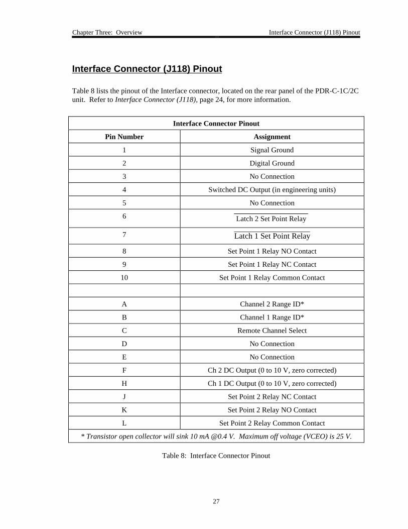
Interface Connector (J118) Pinout
Table 8 lists the pinout of the Interface connector, located on the rear panel of the PDR-C-1C/2Cunit. Refer to Interface Connector (J118), page 24, for more information.
Interface Connector Pinout
Pin Number Assignment
1 Signal Ground
2 Digital Ground
3 No Connection
4 Switched DC Output (in engineering units)
5 No Connection
6 Latch 2 Set Point Relay
7 Latch 1 Set Point Relay
8 Set Point 1 Relay NO Contact
9 Set Point 1 Relay NC Contact
10 Set Point 1 Relay Common Contact
A Channel 2 Range ID*
B Channel 1 Range ID*
C Remote Channel Select
D No Connection
E No Connection
F Ch 2 DC Output (0 to 10 V, zero corrected)
H Ch 1 DC Output (0 to 10 V, zero corrected)
J Set Point 2 Relay NC Contact
K Set Point 2 Relay NO Contact
L Set Point 2 Relay Common Contact
* Transistor open collector will sink 10 mA @0.4 V. Maximum off voltage (VCEO) is 25 V.
Table 8: Interface Connector Pinout
Pressure Sensor Terminal Block Connections Chapter Three: Overview
28
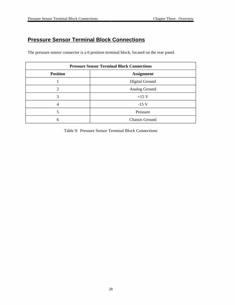
Pressure Sensor Terminal Block Connections
The pressure sensor connector is a 6 position terminal block, located on the rear panel.
Pressure Sensor Terminal Block Connections
Position Assignment
1 Digital Ground
2 Analog Ground
3 +15 V
4 -15 V
5 Pressure
6 Chassis Ground
Table 9: Pressure Sensor Terminal Block Connections
Chapter Four: Theory of Operation Pressure Signal
29
Chapter Four: Theory of Operation
Pressure Signal
The pressure signal is received from the pressure gauge at the rear panel terminal block and isapplied to the input amplifier (U1) where the fine zero correction is added. The output from thisamplifier then goes to the output buffer amplifiers (U2, U3) and to the rear panel Interfaceconnector. The output from the input amplifier also goes to the set point switching circuits(through the rear panel Channel Select switches on the PDR-C-2C) and to the Engineering Unitsscaling circuit (through the DVM selection relay on the PDR-C-2C) which leads ultimately to thedisplay DVM.
Set Points
Two independent set point relays and their respective switching circuits are included in both thePDR-C-1C and -2C. In the -2C these set points can be selected to monitor either incoming pressuresignal by means of rear panel channel selection switches.
The set point circuit compares the incoming pressure signal with an adjustable reference voltagewhich is set using the front panel Coarse and Fine adjustment controls. The relay logic is such thata no-power condition produces the same relay states that a high-pressure situation will produce.Either set point value may be read on the display DVM in engineering units by toggling the frontpanel READ switch toward the appropriate side. Asserting either LATCH line on rear panelconnector J118 will hold the set point relays de-energized once that state has been reached.
Overrange Comparator
This circuit monitors the input to the engineering units circuit and causes the display to blank whena pressure signal of approximately 11 or more Volts occurs.
Power Supply
The power supply provides ±15 Volts for internal circuits as well as for the attached pressuregauge. The + and - supplies are identical and are internally protected against shorts andoverheating. This supply also generates the precision reference voltage used by the comparators.The display DVM provides its own +5 Volt source which is also used as the supply for 5 Volt logicon the main PC board.

Pressure Level Comparators Chapter Four: Theory of Operation
30
Pressure Level Comparators
PDR-C-2C only
The channel 1 pressure signal is applied to two comparators.
One of these is set to trip at 90% of full scale pressure while the other is set for 100%. Thecomparator outputs are connected to logic whose output goes to the front panel ChannelSelector/Function Switch.
Channel Selector / Function Switch
PDR-C-2C only
This switch is used to determine which channel’s output is displayed by the front panel DVM bychoosing which logic level or input is applied to the channel select relay (K1). If the AUTO switchposition is chosen then the logic output from the pressure level comparators is applied to the relayswitching transistor. Front panel LEDs are used to indicate which channel is being displayed.When the Channel Selector/Function Switch is set to the REMOTE position the user can remotelyselect which channel is being displayed by inserting the appropriate logic level on pin C of the rearpanel Interface connector.
Chapter Five: Maintenance General Information
31
Chapter Five: Maintenance
General Information
Periodically check for wear on the cables and inspect the enclosure for visible signs of damage.
Should any difficulties be encountered in the use of your instrument, refer to Customer Support,page 18, for instructions on how to return the product to MKS.
Should it become necessary to attempt repair in the field, the first step is to isolate the source of theproblem to the pressure gauge or the PDR. Any repair made to the pressure gauge will usuallyrequire a recalibration. The PDR-C-1C/2C may be repaired without recalibration as long as none ofthe calibration adjustments have been tampered with.
Fault Isolation
The first step in troubleshooting is to isolate the problem to one of the sections of the PDR. Oncethis is done the problem can usually be easily located and corrected. The PDR-C-1C/2C can bebroken down into the following sections:
• Power Supply
• Pressure Signal Amplification and Readout
• Set Point Circuits
• Channel Selection Circuits (PDR-C-2C only)
Since a problem in the power supply will effect the performance of all sections, it is important to begin faultisolation at this point.
Fault Isolation Chapter Five: Maintenance
32
Power Supply
1. Measure the ±15 Volt supplies on the rear panel pressure gauge connector with respectto P GND.
The voltages should be within the range of 14.8 to 15.2 Volts and the AC ripple shouldbe less than 10 mV peak-to-peak. If the voltages appear to be normal, then proceed tocheck the next section. If supply voltages are incorrect, continue with the step 2.
2. Disconnect the pressure gauge and retest the supply voltages.
If the supplies now appear to be normal, the fault is with the pressure sensor. If thesupplies are not normal after removing the pressure sensor, continue with step 3.
3. Remove the power supply jumpers (E1-E2 and E3-E4) in order to isolate the powersupply from the rest of the PDR circuits.
If the supplies now are normal, the fault is probably a short circuit in the PDR circuits.If the supplies continue to appear abnormal, contact MKS for assistance.
Pressure Signal Amplification and Readout
1. Set up the PDR so that it is displaying the output in mmHg from a connected pressuregauge.
2. At the rear panel terminal block, connect an external voltmeter between Signal GND andthe Pressure Input.
If this voltage closely tracks1 (±0.2 V) the voltage that is displayed on the front panelDVM but is not representing the correct pressure, the pressure gauge is in error and thePDR unit is operating normally.
If the voltage does not track, continue to troubleshoot the PDR unit.
To troubleshoot the signal path of the PDR-C-1C/2C, disconnect the pressure gauge andreplace it with two resistors connected in the following manner:
Note If you have a PDR-C-2C, connect the resistors to Channel 1 and placechannel selector to Channel 1.
1 A voltage of above approximately 10.8 Volts will cause the digital panel meter to overrange and blank. Thisis to be considered normal.
Chapter Five: Maintenance Fault Isolation
33
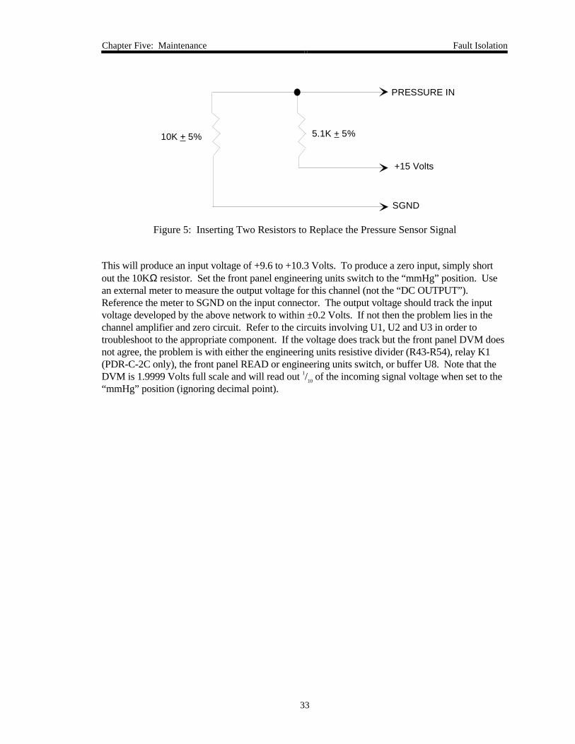
PRESSURE IN
+15 Volts
SGND
10K + 5% 5.1K + 5%
Figure 5: Inserting Two Resistors to Replace the Pressure Sensor Signal
This will produce an input voltage of +9.6 to +10.3 Volts. To produce a zero input, simply shortout the 10KΩ resistor. Set the front panel engineering units switch to the “mmHg” position. Usean external meter to measure the output voltage for this channel (not the “DC OUTPUT”).Reference the meter to SGND on the input connector. The output voltage should track the inputvoltage developed by the above network to within ±0.2 Volts. If not then the problem lies in thechannel amplifier and zero circuit. Refer to the circuits involving U1, U2 and U3 in order totroubleshoot to the appropriate component. If the voltage does track but the front panel DVM doesnot agree, the problem is with either the engineering units resistive divider (R43-R54), relay K1(PDR-C-2C only), the front panel READ or engineering units switch, or buffer U8. Note that theDVM is 1.9999 Volts full scale and will read out 1/10 of the incoming signal voltage when set to the“mmHg” position (ignoring decimal point).

Fault Isolation Chapter Five: Maintenance
34
How To Calibrate the Engineering Units Circuit
Equipment Required:
1 DVM, 5½ place
1 Precision Variable Voltage Source, 10 Volts
Miscellaneous Bus Wire
Schematic
PC Layout
1. Turn off power to the PDR-C unit.
2. Short the Pressure Input to the Signal GND terminal on the rear panel terminal block(CH 1).
3. Attach the DVM between Analog GND and the zeroed CH 1 signal, available at front panelswitch S3 or at one end of R43.
4. Apply power to the PDR unit.
5. Adjust the front panel ZERO trimmer for a 0.000 ±0.0005 Volt DVM reading.
6. Shut off power to the PDR.
7. Attach the voltage source between the Pressure Input and Signal GND terminals.
8. Apply power and a voltage source of 10.0000 ±0.0005 Volts, as measured by the DVM.
9. Ignore the decimal point on the front panel display and use Table 10 to set the appropriatetrimmer for a correct display of the chosen engineering units.
Correct Trimmer for Selected Engineering Units
Engineering Units Trimmer Front Panel DVM
mbar R47 13332
kPa R47 13332
mmHg R49 10000
psi R44 19337
cmH2O R55 13597
inH2O R51 5353
in Hg R53 3937
Table 10: Correct Trimmer for Selected Engineering Units
Chapter Five: Maintenance Fault Isolation
35
Set Point Circuits
With the input section zeroed and 10 Volts input applied as described above in “Calibrationof Engineering Units” (place PDR-C-2C rear panel SET POINT switches in “CH 1”position), check voltages at U20 pin 5 and U16 pin 3 to be 10.000 Volts. If not, checkcontinuity from R5 and R6 through jumpers E7-E8 and E9-E10 (PDR-C-1C) or throughrear panel switches S7 and S8 (PDR-C-2C).
If 10 Volts is read at U20 and U16 then check the voltage at U20 pin 3 and verify it withthe front panel DVM, with engineering units set to “mmHg” position. Do this by movingthe front panel SET POINT switch to the left for CH 1. Similarly check U16 pin 5 to bethe same as the front panel display with the SET POINT switch to the right (CH2).Varying the COARSE and FINE set point trimmers should vary the display voltagesaccordingly.
By changing the incoming “pressure” signal from the voltage source to be close to the set pointvoltage, the outputs of both set point comparators (U18A pin 1 and U18B pin 7) should switchbetween the positive and negative supply rails. This in turn should cause U17 pins 10 and 4 to varyinversely between 0 Volts and the positive supply (be sure the LATCH lines are in a high state-U17pin 12 and pin 1). Next check the outputs from U19 pins 1 and 7 to ensure switching between rails.If the above all works, any problem must be with the relay drivers Q5 and Q6 or relays K2 and K3and associated components.
Channel Selection Circuits
PDR-C-2C only
If no channel selection is indicated, check J113 pin 2 to be connected to digital ground andJ113 pin 1 to be +5 Volts. If digital ground is at fault, check continuity back to the powersupply. If +5 Volts is at fault, check wiring from the front panel DVM (+5 Volt supplycomes from the DVM!). If both are fine and no channel switching occurs, check thecollector voltages of Q1 and Q2 to verify that one is at 0 Volts and the other is at +15Volts. If this is correct check that relay K1 is switching when changing channel selectionfrom CH 1 to CH 2 and back. If remote channel selection malfunctions, check U6 pin 4 tobe switching inversely to an applied +5 Volt logic signal on rear panel Interface connector(J118) pin C.
If problems exist with the AUTO channel selection circuit, first select AUTO operation and attachthe voltage source to channel 1 Pressure Input as previously described. While monitoring thevoltage at U4 pin 1, vary the incoming voltage from approximately 8 Volts up to 11 Volts notingthat U4 pin 1 should switch high at approximately 10 Volts input. If not, check circuit or adjustR16. Next do the same test while monitoring U4 pin 7, noting that switching should occur withapproximately 9 Volts input. If this all checks out, next measure U5 pin 4 to be switching high atapproximately 10 Volts as the input increases from 8 Volts. Next decrease from 11 Volts and noteU5 pin 4 to be switching low as the input voltage equals approximately 9 Volts. If this ishappening and automatic channel selection is not occurring, the relay (K1) driver circuits are atfault.

Fault Isolation Chapter Five: Maintenance
36
This page intentionally left blank.
Appendix A: Product Specifications Physical Specifications
37
Appendix A: Product Specifications
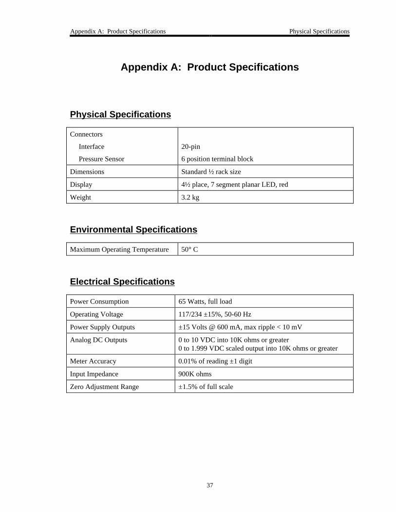
Physical Specifications
Connectors
Interface
Pressure Sensor
20-pin
6 position terminal block
Dimensions Standard ½ rack size
Display 4½ place, 7 segment planar LED, red
Weight 3.2 kg
Environmental Specifications
Maximum Operating Temperature 50° C
Electrical Specifications
Power Consumption 65 Watts, full load
Operating Voltage 117/234 ±15%, 50-60 Hz
Power Supply Outputs ±15 Volts @ 600 mA, max ripple < 10 mV
Analog DC Outputs 0 to 10 VDC into 10K ohms or greater0 to 1.999 VDC scaled output into 10K ohms or greater
Meter Accuracy 0.01% of reading ±1 digit
Input Impedance 900K ohms
Zero Adjustment Range ±1.5% of full scale
Set Point Specifications Appendix A: Product Specifications
38
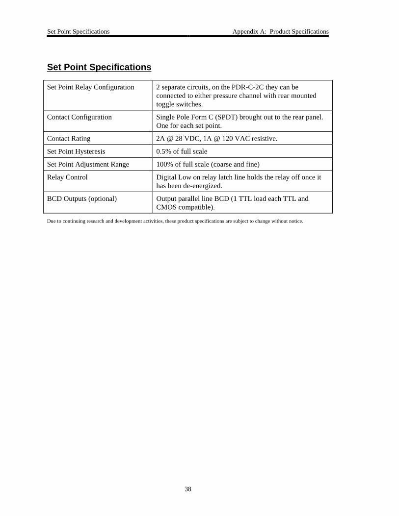
Set Point Specifications
Set Point Relay Configuration 2 separate circuits, on the PDR-C-2C they can beconnected to either pressure channel with rear mountedtoggle switches.
Contact Configuration Single Pole Form C (SPDT) brought out to the rear panel.One for each set point.
Contact Rating 2A @ 28 VDC, 1A @ 120 VAC resistive.
Set Point Hysteresis 0.5% of full scale
Set Point Adjustment Range 100% of full scale (coarse and fine)
Relay Control Digital Low on relay latch line holds the relay off once ithas been de-energized.
BCD Outputs (optional) Output parallel line BCD (1 TTL load each TTL andCMOS compatible).
Due to continuing research and development activities, these product specifications are subject to change without notice.
Appendix B: Model Code Explanation Model Code
39
Appendix B: Model Code Explanation
Model Code
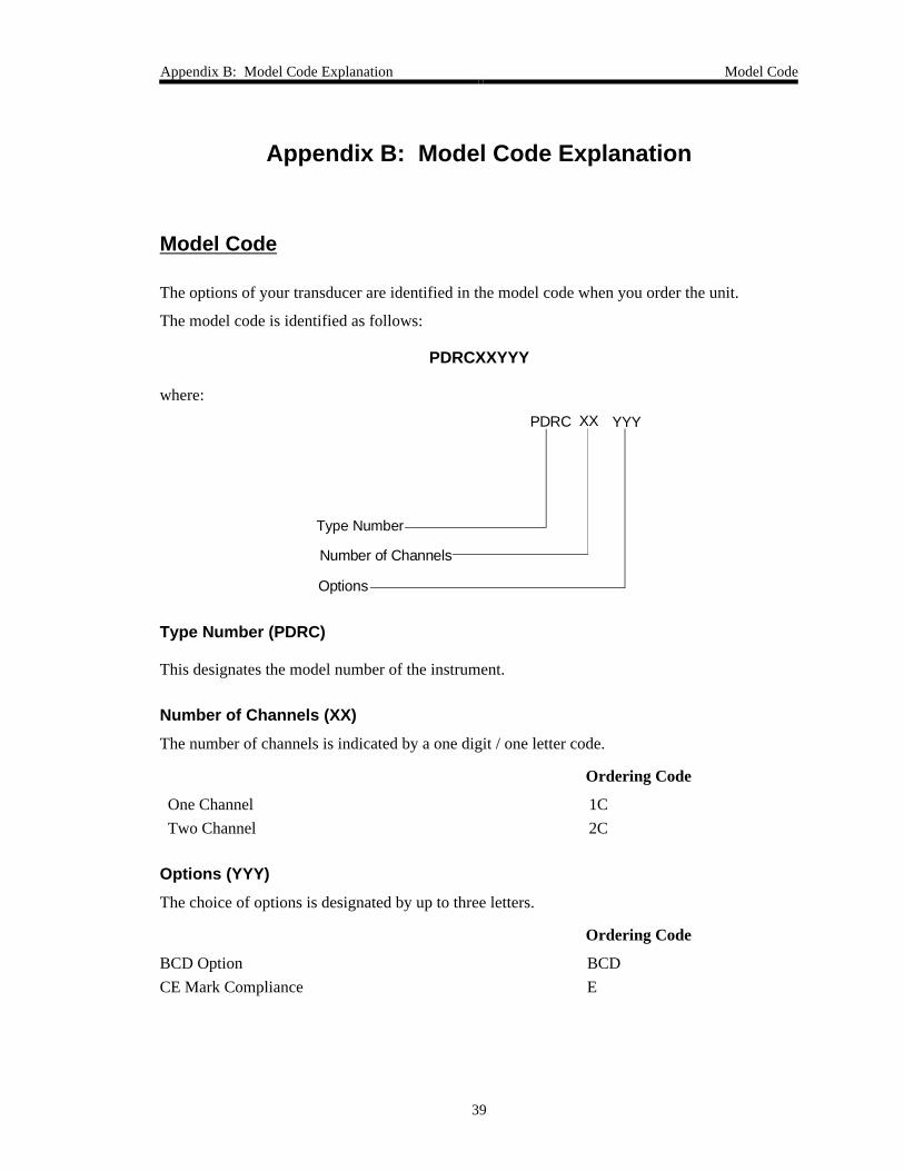
The options of your transducer are identified in the model code when you order the unit.
The model code is identified as follows:
PDRCXXYYY
where:
Type Number
Number of Channels
Options
XX YYYPDRC
Type Number (PDRC)
This designates the model number of the instrument.
Number of Channels (XX)
The number of channels is indicated by a one digit / one letter code.
Ordering Code
One Channel 1C
Two Channel 2C
Options (YYY)
The choice of options is designated by up to three letters.
Ordering Code
BCD Option BCD
CE Mark Compliance E

Model Code Appendix B: Model Code Explanation
40
This page intentionally left blank.
Appendix C: BCD Option General Information
41
Appendix C: BCD Option
General Information
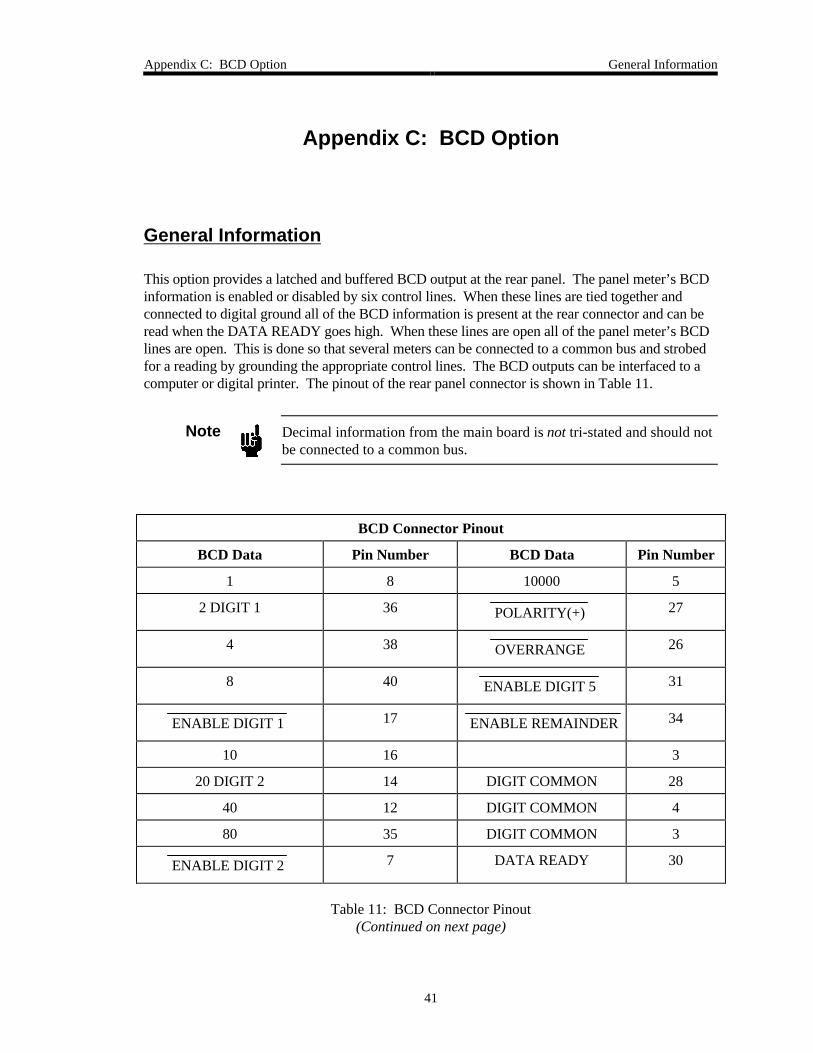
This option provides a latched and buffered BCD output at the rear panel. The panel meter’s BCDinformation is enabled or disabled by six control lines. When these lines are tied together andconnected to digital ground all of the BCD information is present at the rear connector and can beread when the DATA READY goes high. When these lines are open all of the panel meter’s BCDlines are open. This is done so that several meters can be connected to a common bus and strobedfor a reading by grounding the appropriate control lines. The BCD outputs can be interfaced to acomputer or digital printer. The pinout of the rear panel connector is shown in Table 11.
Note Decimal information from the main board is not tri-stated and should notbe connected to a common bus.
BCD Connector Pinout
BCD Data Pin Number BCD Data Pin Number
1 8 10000 5
2 DIGIT 1 36 POLARITY(+) 27
4 38 OVERRANGE 26
8 40 ENABLE DIGIT 5 31
ENABLE DIGIT 1 17 ENABLE REMAINDER 34
10 16 3
20 DIGIT 2 14 DIGIT COMMON 28
40 12 DIGIT COMMON 4
80 35 DIGIT COMMON 3
ENABLE DIGIT 2 7 DATA READY 30
Table 11: BCD Connector Pinout(Continued on next page)
General Information Appendix C: BCD Option
42
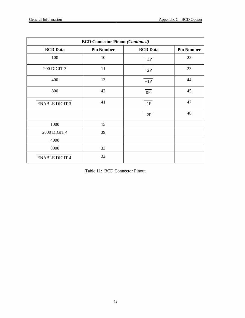
BCD Connector Pinout (Continued)
BCD Data Pin Number BCD Data Pin Number
100 10 +3P 22
200 DIGIT 3 11 +2P 23
400 13 +1P 44
800 42 0P 45
ENABLE DIGIT 3 41 -1P 47
-2P 48
1000 15
2000 DIGIT 4 39
4000
8000 33
ENABLE DIGIT 4 32
Table 11: BCD Connector Pinout
Index
43
Index
B
BCD, 24, 25, 39, 41–42
C
Cables, 22
CE compliance, 39
Channels
two, 26, 35
Channels, number, 39
Chassis ground, 22
Connector
Interface, 24, 27, 29
Power, 24
Pressure Sensor, 23, 28
Customer support, 18
D
Decimal point, 23
Display, 17, 23, 25, 37
E
Engineering units, 17, 25
F
Failsafe, 17
Fault isolation, 31
Fuses, 24
G
Ground, 22
I
Interface cables, 22
Interface connector, 24, 27, 29
M
Manual organization, 18
Model code, 39
O
Options, 39
Overrange, 29
P
Power connector, 24
Power consumption, 37
Power supply, 17, 29, 32
Pressure Sensor connector, 23, 28
Pressure units, 17, 25
R
Relay, 17, 24, 27, 29, 38
Remote, 26, 30
Returning the product, 18, 19
S
Set point, 17, 24, 25, 27, 29, 35, 38
T
Temperature, 20
Index
44
U
Units, 17, 25
V
Ventilation, 20, 22
Z
Zero, 25