
mjmyachts@verizon · 401-862-4367 . [email protected] May 2015 Dear 50z Owner: Congratulations...
72
401-862-4367 . [email protected] May 2015 Dear 50z Owner: Congratulations on becoming Captain and Owner of the world’s best built and most fuel efficient yacht of its size. This 50z Owner’s Manual should further contribute to your enjoyment and proficiency afloat. This manual was created jointly with Zurn Yacht Design, Boston BoatWorks and MJM Yachts. Our experience with the first 190 boats (all models included) has been incorporated to make this manual as useful and relevant as possible. Keep in mind that there maybe some variances or custom additions to your boat which were installed after printing of this manual. And, from time-to-time we will change specifications to keep pace with changes made to improve the boat. When addressing a problem with a specific piece of equipment, this 50z Owner’s Manual is to be regarded only as a preliminary source of information. The equipment manufacturer’s own manual with trouble-shooting procedures, etc. is the primary source and authority. And starting with the 50z , in addition to two large binders with hard copies of equipment manuals, you will find a CD disc with a digital copies you can access on your computer, carry around with you and consult when convenient… like when commuting on AMTRAK instead of reading the morning paper. A Small Craft Owner’s Manual accompanies, and forms part of, this 50z Owner Manual. This booklet has universal handling and operating tips worth reviewing. This 50z Owner’s Manual is designed to be a living document, not only for builder updates but for your own use and record. Each boat is provided with a copy of the current Manual organized in a STAPLES “Mini-Ring” type binder that allows you to add pages as needed. One of the great advantages of purchasing a series-built or semi-custom design is that owners have the benefit of learning from one another. So, with your continued input and comments we can keep adding useful information and helpful hints to this manual. Part of the ISO CE Mark Certification Program is confirmation by the owner that the manual has been received. Please sign the extra page No. 3 included in the Manual as a receipt and return it in the stamped envelope provided. Best wishes for fair winds and sunny skies. On behalf of the builder and designer, we are most appreciative, and I am particularly honored, that you have chosen the 50z. Robert L. Johnstone Founder & CEO Note: This manual is published in accordance with ISO standard 10240:1995E Small Craft - Owner’s Manual
Transcript of mjmyachts@verizon · 401-862-4367 . [email protected] May 2015 Dear 50z Owner: Congratulations...

401-862-4367 . [email protected]
May 2015 Dear 50z Owner:
Congratulations on becoming Captain and Owner of the world’s best built and most fuel efficient yacht of its size. This 50z Owner’s Manual should further contribute to your enjoyment and proficiency afloat. This manual was created jointly with Zurn Yacht Design, Boston BoatWorks and MJM Yachts. Our experience with the first 190 boats (all models included) has been incorporated to make this manual as useful and relevant as possible. Keep in mind that there maybe some variances or custom additions to your boat which were installed after printing of this manual. And, from time-to-time we will change specifications to keep pace with changes made to improve the boat. When addressing a problem with a specific piece of equipment, this 50z Owner’s Manual is to be regarded only as a preliminary source of information. The equipment manufacturer’s own manual with trouble-shooting procedures, etc. is the primary source and authority. And starting with the 50z , in addition to two large binders with hard copies of equipment manuals, you will find a CD disc with a digital copies you can access on your computer, carry around with you and consult when convenient… like when commuting on AMTRAK instead of reading the morning paper. A Small Craft Owner’s Manual accompanies, and forms part of, this 50z Owner Manual. This booklet has universal handling and operating tips worth reviewing. This 50z Owner’s Manual is designed to be a living document, not only for builder updates but for your own use and record. Each boat is provided with a copy of the current Manual organized in a STAPLES “Mini-Ring” type binder that allows you to add pages as needed. One of the great advantages of purchasing a series-built or semi-custom design is that owners have the benefit of learning from one another. So, with your continued input and comments we can keep adding useful information and helpful hints to this manual. Part of the ISO CE Mark Certification Program is confirmation by the owner that the manual has been received. Please sign the extra page No. 3 included in the Manual as a receipt and return it in the stamped envelope provided. Best wishes for fair winds and sunny skies. On behalf of the builder and designer, we are most appreciative, and I am particularly honored, that you have chosen the 50z.
Robert L. Johnstone Founder & CEO
Note: This manual is published in accordance with ISO standard 10240:1995E Small Craft - Owner’s Manual
BOAT%INFORMATION%%%MODEL% % % % 50z%Downeast%HIN%NUMBER%% % % EOU50z04C516%DESIGN%PATENT% % % US%D475%338S%(3%June%2003)%DELIVERY%DATE% % % May%2015%REGISTRATION%NO.% % % ________________________________%%ENGINES% % % % VolvoPPenta%MODEL% % % % IPS%600%D6%435D%%%EVC%E%SERIAL%NOS.%%%%%%%%%%%%%%%%%%%%%%%%%%%%%%%%%%%%%%%%%%A364865,%A364866,%A364867%VOLVO%24%HR%SERVICE% % 877P747P3682%VOLVO%MJM%CONTACT% % Joel%Rumelhart%207P632P6868%%DRIVES% % % % VolvoPPenta%MODEL% % % % IPS%Transmission%1.82:1%SERIAL%NO.% % % % 3940016632,%3940016988%&%%3940016989%PROPELLOR% % % % T6%Props%Part%#3861104%%MJM%YACHTS%LLC% % % Robert%L.%Johnstone%PHONE% % % % 401P862P4367%Mobile%EMAIL%% % % % [email protected]%ADDRESS% % % % Box%8,%Newport%RI%02840%%ZURN%YACHT%DESIGN% % Doug%Zurn%PHONE% % % % 781P639P0678%ADDRESS% % % % 89%Front%St.,%Marblehead%MA%01945%%BOSTON%BOATWORKS%LLC% % Scott%Smith%&%Mark%Lindsay%PHONES% % % % 207P252P7190%% % % % % 617P561P9111%EMAIL%% % % % [email protected]%ADDRESS% % % % 256%Marginal%St.,%East%Boston%MA%02128%%BBW%SERVICE%REP% % % Erik%Rochelle%PHONE% % % % 207P400P7182%EMAIL%% % % % [email protected]%%DEALER% % % % MJM%YACHTS%%BROKER% % % % Bob%Johnstone%PHONE% % % % (above)%EMAIL%% % % % %% % % % %

®
50z Owner’s Manual
LOA - Length Overall w/Swim Platform & Bow Roller & Rail 55’ 3” LOD - Length On Deck 50’ 0” Beam 15’ 0” Draft Twin IPS 2’ 11” Triple I/0 3’ 3” Triple IPS 3’ 10” Displacement – ½ Load 32,850 lbs. Fuel Tankage - Two 260 Gallon Tanks 520 gals. Fresh Water Tankage – Including Hot Water Tank 170 gals. Holding Tank w/Macerator Overboard Discharge 30 gals. Air Height over Water w/Radar Mounted on Hard Top 10’ 6” Headroom Bridgedeck 7’ 0” Wheel 6’ 4”- 6’ 8” Belowdecks 6’ 4” – 6’ 5”
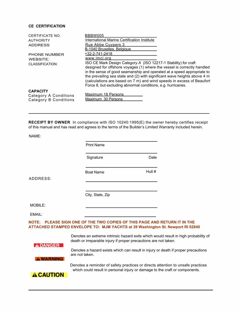
CE CERTIFICATION CERTIFICATE NO. AUTHORITY ADDRESS PHONE NUMBER
WEBSITE: CLASSIFICATION:
CAPACITY Category A Condit ions
Category B Condit ions
-------------------------------------------------------------------------------------------------------------------------------------------- RECEIPT BY OWNER In compliance with ISO 10240:1995(E) the owner hereby certifies receipt of this manual and has read and agrees to the terms of the Builder’s Limited Warranty included herein.
Print Name
Boat Name
City, State, Zip
NOTE: PLEASE SIGN ONE OF THE TWO COPIES OF THIS PAGE AND RETURN IT IN THE ATTACHED STAMPED ENVELOPE TO: MJM YACHTS at 39 Washington St. Newport RI 02840
Denotes an extreme intrinsic hazard exits which would result in high probability of death or irreparable injury if proper precautions are not taken.
Denotes a hazard exists which can result in injury or death if proper precautions are not taken.
Denotes a reminder of safety practices or directs attention to unsafe practices
which could result in personal injury or damage to the craft or components.
International Marine Certification Institute Rue Abbe Cuypers 3 B-1040 Bruxelles, Belgique +32-2-741-2418
ISO CE Mark Design Category A (ISO 12217-1 Stability) for craft designed for offshore voyages (1) where the vessel is correctly handled in the sense of good seamanship and operated at a speed appropriate to the prevailing sea state and (2) with significant wave heights above 4 m (calculations are based on 7 m) and wind speeds in excess of Beaufort Force 8, but excluding abnormal conditions, e.g. hurricanes.
Maximum 18 Persons Maximum 30 Persons
BBBW005
www.imci.org
NAME:
Signature Date
Hull #
ADDRESS:
MOBILE: EMAIL:
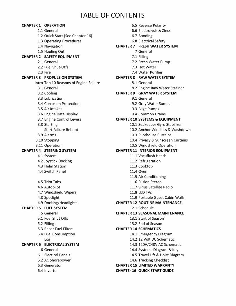
! !!!!!!!!!!!!!!!!!!!!TABLE!OF!CONTENTSCHAPTER(1( OPERATION 6.5 Reverse!Polarity
1.1 General 6.6 Electrolysis!&!Zincs1.2 Quick!Start!(See!Chapter!16) 6.7 Bonding1.3 Operating!Procedures 6.8 Electrical!Safety1.4 Navigation CHAPTER(7 FRESH(WATER(SYSTEM1.5 Hauling!Out 7 General
CHAPTER(2 SAFETY(EQUIPMENT 7.1 Filling2.1 General 7.2 Fresh!Water!Pump2.2 Fuel!ShutSOffs 7.3 Hot!Water2.3 Fire 7.4 Water!Purifier
CHAPTER(3 PROPULSION(SYSTEM CHAPTER(8 RAW(WATER(SYSTEMIntro Top!10!Reasons!of!Engine!Failure 8.1 General3.1 General 8.2 Engine!Raw!Water!Strainer3.2 Cooling CHAPTER(9 GRAY(WATER(SYSTEM3.3 Lubrication 9.1 General3.4 Corrosion!Protection 9.2 Gray!Water!Sumps3.5 Air!Intakes 9.3 Bilge!Pumps3.6 Engine!Data!Display 9.4 Common!Drains3.7 Engine!Control!Levers CHAPTER(10 SYSTEMS(&(EQUIPMENT3.8 Starting 10.1 Seakeeper!Gyro!Stabilizer
Start!Failure!Reboot 10.2 Anchor!Windlass!&!Washdown3.9 Alarms 10.3 Pilothouse!Curtains3,10 Stopping 10.4 Privacy!&!Sunscreen!Curtains3,11 Operation 10.5 Windshield!Operation
CHAPTER(4 STEERING(SYSTEM CHAPTER(11 INTERIOR(EQUIPMENT4.1 System 11.1 Vacuflush!Heads4.2 Joystick!Docking 11.2 Refrigeration4.3 Helm!Station 11.3 Cooktop4.4 Switch!Panel 11.4 Oven
11.5 Air!Conditioning4.5 Trim!Tabs 11.6 Fusion!Stereo4.6 Autopilot 11.7 Sirius!Satellite!Radio4.7 Windshield!Wipers 11.8 LED!TVs4.8 Spotlight 11.9 Portable!Guest!Cabin!Walls4.9 Docking/Headlights! CHAPTER(12 ROUTINE(MAINTENANCE
CHAPTER(5 FUEL(SYSTEM 12.1 Schedule5 General CHAPTER(13 SEASONAL(MAINTENANCE
5.1 Fuel!Shut!Offs 13.1 Start!of!Season5.2 Filling 13.2 End!of!Season5.3 Racor!Fuel!Filters CHAPTER(14 SCHEMATICS5.4 Fuel!Consumption! 14.1 Emergency!Diagram
Log 14.2 12!Volt!DC!SchematicCHAPTER(6 ELECTRICAL(SYSTEM 14.3 120V/240V!AC!Schematic
6 General 14.4 Systems!Diagram!&!Key6.1 Electical!Panels 14.5 Travel!Lift!&!Hoist!Diagram6.2 AC!Shorepower 14.6 Trucking!Checklist6.3 Generator CHAPTER(15 LIMITED(WARRANTY6.4 Inverter CHAPTEr(16 QUICK(START(GUIDE

DIGITAL'LIBRARY'of'MJM'50z'EQUIPMENT'MANUALS'CONTENT'of'CD'DISC''!!1A.!MJM!50z!Equipment!Manual!Intro!Letter.doc!1B.!50z!#1!Northern!Lights!Generator!Serial!Number!Sheet.pdf!1C.!50z!#1!Volvo!435HP!IPS!600!Engines!Serial!Number!Sheet.pdf!1D.!MJM!50z!#1!Gelcoat!&!AWLCRAFT!&!Bottom!Paint!Page!IPS.doc!1E.!MJM!50z!Equipment!Registration!Info!(Except!Imtra!&!Seake.xls!1F.!Imtra!Warranty!Statement.pdf!1G.!Seakeeper!Limited!Warranty!Policy!2013!X!2000!HOURS.pdf!1H.!Port!Supply!Battery!Warranty!Jan!29!2008.pdf!1I.!50z!Preliminary!AC!Diagram!Rev3!X!07X24X14.pdf!1J.!50z!Preliminary!DC!Schematic.pdf!Airmar!DT800!Transducer.pdf!Armstrong!Ladder!Care!&!Maint!Sheet!Jan!16!2009.pdf!Aspen!Pumps!Mini!&!Maxi!Orange!Condensate!Pumps.pdf!Attwood!6556X7!LED!Transom!Light.pdf!Attwood!7836S1!Pole!Light.pdf!Awlgrip!Maintenance!of!Topcoats!Sheet.pdf!Barnegat!QLX3294XLED!Headlights.pdf!Blue!Sea!7622!Automatic!Charging!Relay.pdf!Blue!Sea!7700!Remote!Battery!Switch.pdf!Blue!Sea!9012!Solenoid!Switch.pdf!Bomar!50z!Hull!Port.pdf!Bose!Acoustimass!IV!Series!3!Speakers.pdf!Bosworth!Guzzler!500!Manual!Bilge!Pump.pdf!Corian!Care!!Maintenance!Data!Mar!31!2011.pdf!Dometic!36z!&!50z!Holding!System!Parts!Diagrams.pdf!Dometic!500+!and!700!Series!Toilet.pdf!Dometic!506+!Toilet!Parts!Diagram.pdf!Dometic!Tank!Manager.pdf!Dometic!Vacuum!Generator!for!Blackwater!System.pdf!Esthec!Care!&!Cleaning!Instructions!Feb!19!2013.pdf!Florida!Marine!Tanks!Warranty!Statement!Mar!29!2010.doc!Fusion!MSXAV700i!Stereo.pdf!Fusion!MSXDA51600!Amplifier.pdf!Fusion!MSXFR702!Speaker.pdf!General!Ecology!Seagull!IV!XX1F!Water!Filter.pdf!Glendinning!CRRX50!(Use!for!CRMX50).pdf!Groco!ARG!Series!Strainer.pdf!HXP!Products!Dirt!Devil!CV1500!Central!Vacuum.pdf!Indel!Isotemp!Water!Heater.pdf!Jabsco!33ALA!Bilge!Alarm.pdf!Jabsco!98A!Shower!Drain!Box.pdf!

Jabsco!44411X2045!Water!Inlet!Regulator.pdf!Jabsco!63022X0012!Spotlight.pdf!Jabsco!RM1100A!Electric!Bilge!Pump.pdf!Johnson!10X13409X01!Aqua!Jet!Duo!Water!Pressure!Pump.pdf!Kahlenberg!DX0A!Air!Horn.pdf!Kenyon!Lite!Touch!Cooktop.pdf!Lewmar!hatches!and!portlights.pdf!Marine!Air!AHXPassport!IO.pdf!Marine!Air!CW!System.pdf!Marine!Air!DDC.pdf!Muir!VRC!850,1250,2200!Windlass.pdf!Northern!Lights!M773LW3.3!Generator!Operation.pdf!Ocean!Air!Rollershade!Care!&!Maint!Sheet!Jan!15!2009.pdf!Ocean!Air!Skyscreen!Care!&!Maint!Sheet!Jan!15!2009.pdf!ProMariner!FS!Galvanic!Isolator.pdf!Racor!200RMAM!Fuel!Filter!and!Separator.pdf!Racor!500MA!Fuel!Filter!and!Separator.pdf!Racor!LG100!Separator.pdf!Racor!RK19492!Shut!Off!Valve!Kit!Jul!8!2009.pdf!Ritchie!Compass.pdf!Roca!532003!Wiper!Control.pdf!SeaXFire!ESRSXMARK!V!Fire!Suppression!System.pdf!SeaXFire!FDXFG!Fire!Extinguisher.pdf!Seakeeper!9!Gyroscopic!Stabilizer.pdf!Sharp!RX820JS!Microwave.pdf!Sirius!SXV200V!Satellite!Radio!Module.pdf!Stidd!500N!&!500W!Piloting!Seats.pdf!Stidd!1200!&!1200W!Piloting!Seats.pdf!Stratglass!Care!Instructions!Aug!14!2008.pdf!Victron!Centaur!Battery!Charger.pdf!Victron!Phoenix!Inverter!Manual.pdf!Vitrofrigo!DW!180!Refrigerator/Freezer/Icemaker!Vizio!E231iXB1!&!E241iXB1!Television.pdf!Vizio!M321iXA2!Television.pdf!Volvo!Penta!Anode!Installation!Instructions.pdf!Volvo!Penta!IPS!Engines!with!Interceptor!System.pdf!
1.1
1.2
1.3 1.4
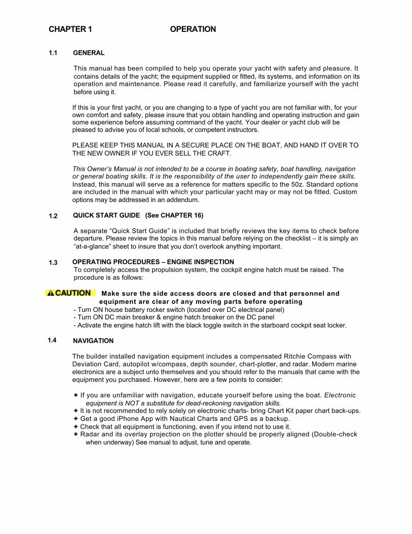
OPERATION GENERAL
This manual has been compiled to help you operate your yacht with safety and pleasure. It contains details of the yacht; the equipment supplied or fitted, its systems, and information on its operation and maintenance. Please read it carefully, and familiarize yourself with the yacht before using it. If this is your first yacht, or you are changing to a type of yacht you are not familiar with, for your own comfort and safety, please insure that you obtain handling and operating instruction and gain some experience before assuming command of the yacht. Your dealer or yacht club will be pleased to advise you of local schools, or competent instructors. PLEASE KEEP THIS MANUAL IN A SECURE PLACE ON THE BOAT, AND HAND IT OVER TO THE NEW OWNER IF YOU EVER SELL THE CRAFT. This Owner’s Manual is not intended to be a course in boating safety, boat handling, navigation or general boating skills. It is the responsibility of the user to independently gain these skills. Instead, this manual will serve as a reference for matters specific to the 50z. Standard options are included in the manual with which your particular yacht may or may not be fitted. Custom options may be addressed in an addendum.
QUICK START GUIDE (See CHAPTER 16)
A separate “Quick Start Guide” is included that briefly reviews the key items to check before departure. Please review the topics in this manual before relying on the checklist – it is simply an “at-a-glance” sheet to insure that you don’t overlook anything important.
OPERATING PROCEDURES – ENGINE INSPECTION To completely access the propulsion system, the cockpit engine hatch must be raised. The procedure is as follows:
Make sure the side access doors are closed and that personnel and equipment are clear of any moving parts before operating
- Turn ON house battery rocker switch (located over DC electrical panel) - Turn ON DC main breaker & engine hatch breaker on the DC panel - Activate the engine hatch lift with the black toggle switch in the starboard cockpit seat locker.
NAVIGATION The builder installed navigation equipment includes a compensated Ritchie Compass with Deviation Card, autopilot w/compass, depth sounder, chart-plotter, and radar. Modern marine electronics are a subject unto themselves and you should refer to the manuals that came with the equipment you purchased. However, here are a few points to consider: + If you are unfamiliar with navigation, educate yourself before using the boat. Electronic
equipment is NOT a substitute for dead-reckoning navigation skills. + It is not recommended to rely solely on electronic charts- bring Chart Kit paper chart back-ups. + Get a good iPhone App with Nautical Charts and GPS as a backup. + Check that all equipment is functioning, even if you intend not to use it. + Radar and its overlay projection on the plotter should be properly aligned (Double-check
when underway) See manual to adjust, tune and operate.
CHAPTER 1

CHAPTER 1
Compass Heading There are 3 heading references for navigation on the 50z: (1) The compass on the dash, (2) Autopilot digital compass, and (3) GPS COG (Course Over Ground). All of these headings should be within a degree or so of each other when underway. If not, it is recommended that differences be recorded on a deviation card. Use COG as the primary reference at a time when you are not influenced by wind/wave/tidal set.
Boat Speed Rather than a paddle wheel or sonic device, the Raymarine C120 plotter is used to generate SOG (Speed Over Ground) that is displayed by the chart-plotter and may also be shown in larger digits on the Autopilot display. Eventually, you will learn to approximate boat speed through the water by relating it to RPM on the tachometer.
1.5 Hauling & Blocking A facility that is unfamiliar with the 50z may require information before hauling the boat with a Travelift or crane & straps. Refer to the illustration included at the back of this manual. The keel (centerline of the boat) and chines (edges) should be used to position weight-bearing supports. You will note that the fore and aft lift points are located approximately at either end of the pilothouse... e.g. abeam of the windshield and the aft end of the hard top.
Point loading flat areas other than centerline and chine or setting the weight of the hull on supports of insufficient area may result in damage to the hull.
OPERATION
Avoid storing steel or iron items such as tools nearby any compass.
2.1
SAFETY EQUIPMENT
GENERAL
Spend time reviewing where your safety equipment is and how it functions BEFORE you need it. Remember, the best way to protect yourself and others from accidents is to eliminate potential causes of accidents before they occur. Good seamanship and common sense go a long way in this endeavor. Here is a safety checklist derived in part from the USCG Vessel Check List. State Regulations may vary: PFD’s A wearable USCG approved personal flotation device (life-jacket) must be provided for each person aboard. On the 50z, these can be types I, II, III or V. Also, one type IV throwable PFD must be immediately available for use. Children under 13 years of age are required to wear a USCG life jacket that fits when underway unless they are in an enclosed cabin or belowdecks. Visual Distress Signals (VDS) You must carry VDS’s aboard. If operating between sunset and sunrise, they must be suitable for night use and be within the age dates marked on the side of the flares. A minimum of 3 day/night use combination pyrotechnic flares are required. For a list of USCG approved devices, see the USCG recreational checklist. Fire Extinguisher In addition to the automatic fire suppression system fitted in the engine space, you are required to carry at least two type B-1 extinguishers aboard, which are located in the galley and outboard of the starboard helm seat. This should be checked regularly. EPIRB Especially if operating offshore, an EPIRB (electronic position indicating radio beacon) is recommended. Ships Papers & Registration You should carry the vessel’s registration papers and number plate. Pollution Regulation Plaques 5”x8” Oil Discharge Plaque and a 4”x9” Waste Discharge Placard should be fixed were visible. Charts & Light Lists Charts, light lists and a USCG required copy of the Inland “Rules of the Road” Navigation Rules Horn or Whistle Recommended to signal intentions or signal position. For instance, when in a narrow channel or the Intracoastal Waterway: To signal which side of another boat you will pass on, blow 1 blast if you are passing to their starboard side and 2 blasts if passing on their port side. The Kahlenburg horn has a repetitive automatic fog signal that can be activated for either underway or at anchor. Life Raft If you plan to be coastal cruising out of sight of land, it is prudent to carry a Coastal Life Raft which come in compact sizes that can be stored in one of the aft cockpit lockers. Heaving Line These floating lines are available and handy to have ready in case of emergency or to simply trail behind the boat when swimming, .with the end attached to one of the stern cleats.
CHAPTER 2

2.2
2.3
SAFETY EQUIPMENT
First Aid Kit Not a place to scrimp. It is advisable to carry a good, comprehensive, and well-organized (by injury) marine first-aid kit with manual. We recommend that it be stored in the head and that everyone onboard be informed of its location. To deal with cuts that may require stitches in most instances, Dermabond capsules are a good quick substitute. (Remember, you may be the one in need of it!) Companionway Hatch Board or Closure A sliding companionway hatch is provided to close off the interior of the vessel. We recommned keeping this closed when not in use at all times underway… not only to to comply with ISO requirements for cockpit draining but for quieter operation and to prevent anyone from being pitched below if the boat deaccelerates for any reason. With the lid closed as well, it’s a perfect place for a Chart Kit navigation surface. FUEL SHUT-OFF VALVES
The fuel shut-off valves are located on top of the fuel tanks and are accessible through pilothouse settee lockers. Make sure you know how to shut off the fuel valve. In case of a fuel fire, STOP any machinery and close the valves to the engine and genset to cut the supply of fuel to the fire/engine. If you should ever see fuel in the bilges, turn off the valves, clean the bilges, and find the source of the leak immediately. Also note that there are fuel shut off valves, normally left open, on the lower inboard aft corner of the fuel tanks, which connect the two tanks together at the bottom for self-leveling.
FIRE
Fire aboard a boat is a serious matter, and fire safety begins with fire prevention. You can reduce the risk of fire by following common sense guidelines:
+ Do not allow debris or oily rags to collect in bilges or machinery spaces. + Understand your electrical system, allow only qualified marine electricians to work on it, and shut
down as many circuits as practical when leaving the boat. Do not leave appliances running while unattended.
+ Have your fire suppression equipment inspected regularly and learn how to use it. An automatic fire suppression system is installed on every boat in the engine space. It is heat activated. Read the information that comes with the equipment. The system can also be manually activated at the helm station. [See Helm Console Section] Because a diesel engine would evacuate the suppression agent from the affected space, the system will shut down the engine (and generator) when it discharges. If manually activating the system, the engine should be shut down first. After the situation has stabilized, the shut-down feature can be over-ridden to restart the engine. A loud warning alarm will sound when the system has been activated. The hand-held fire extinguishers mounted in the galley, usually under the sink, and outboard of the starboard helm seat is rated to fight type A, B & C fires. To extinguish a fire, the most effective method is to cut the source of fuel to the fire. In the case of a diesel fuel fire, the fuel tank valves should be closed. In the case of an electrical fire, the main battery switches or main disconnect breakers should be turned off. Fire needs oxygen to burn, so if a fire should occur in an enclosed area, the best course of action may be to exit the area and seal it from the outside by closing all means of air intake
CHAPTER 2
CHAPTER 3
INTRO - THE TOP 10 CAUSES OF ENGINE FAILURE
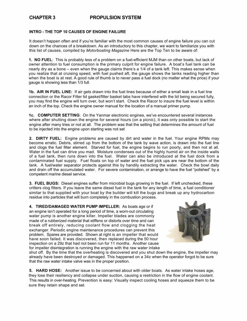
It doesn’t happen often and if you’re familiar with the most common causes of engine failure you can cut down on the chances of a breakdown. As an introductory to this chapter, we want to familiarize you with this list of causes, compiled by Motorboating Magazine Here are the Top Ten to be aware of: 1. NO FUEL: This is probably less of a problem on a fuel-efficient MJM than on other boats, but lack of owner attention to fuel consumption is the primary culprit for engine failure. A boat’s fuel tank can be nearly dry as a bone – even when the gauge claims there’s a 1/4 of a tank left. This makes sense when you realize that at cruising speed, with fuel pushed aft, the gauge shows the tanks reading higher than when the boat is at rest. A good rule of thumb is to never pass a fuel dock (no matter what the price) if your gauge is showing less than 1/3 full. 1b. AIR IN FUEL LINE: If air gets drawn into the fuel lines because of either a small leak in a fuel line connection or the Racor Filter lid gasket/filter basket tabs have interfered with the lid being secured fully, you may find the engine will turn over, but won’t start. Check the Racor to insure the fuel level is within an inch of the top. Check the engine owner manual for the location of a manual primer pump. 1c. COMPUTER SETTING: On the Yanmar electronic engines, we’ve encountered several instances where after shutting down the engine for several hours (on a picnic), it was only possible to start the engine after many tries or not at all. The problem was that the setting that determines the amount of fuel to be injected into the engine upon starting was not set 2. DIRTY FUEL: Engine problems are caused by dirt and water in the fuel. Your engine RPMs may become erratic. Debris, stirred up from the bottom of the tank by wave action, is drawn into the fuel line and clogs the fuel filter element. Starved for fuel, the engine begins to run poorly, and then not at all. Water in the fuel can drive you mad. Moisture condenses out of the highly humid air on the inside walls of a fuel tank, then runs down into the fuel. Water can also be introduced at the fuel dock from a contaminated fuel supply. Fuel floats on top of water and the fuel pick ups are near the bottom of the tank. A fuel/water separator protects against this by handily extracting the water. Check the bowl daily and drain off the accumulated water. For severe contamination, or arrange to have the fuel “polished” by a competent marine diesel service. 3. FUEL BUGS: Diesel engines suffer from microbial bugs growing in the fuel. If left unchecked, these critters clog filters. If you leave the same diesel fuel in the tank for any length of time, a fuel conditioner similar to that supplied with your boat by the builder will kill the bugs and break up any hydrocarbon residue into particles that will burn completely in the combustion process. 4. TIRED/DAMAGED WATER PUMP IMPELLER: As boats age or if an engine isn’t operated for a long period of time, a worn-out circulating water pump is another engine killer. Impeller blades are commonly made of a rubberized material that stiffens or distorts over time and can break off entirely, reducing coolant flow and clogging the heat exchanger. Periodic engine maintenance procedures can prevent this problem. Spares are provided. Shown at right is an impeller that would have soon failed. It was discovered, then replaced during the 50 hour inspection on a 29z that had not been run for 11 months. Another cause for impeller disintegration is running the engine with the raw water intake shut off. By the time that the overheating is discovered and you shut down the engine, the impeller may already have been destroyed or damaged. This happened on a 34z when the operator forgot to be sure that the raw water intake valve was in the proper position. 5. HARD HOSE: Another issue to be concerned about with older boats. As water intake hoses age, they lose their resiliency and collapse under suction, causing a restriction in the flow of engine coolant. This results in over-heating. Prevention is easy: Visually inspect cooling hoses and squeeze them to be sure they retain shape and set.
PROPULSION SYSTEM
CHAPTER 3
6. CLOGGED INTAKE: Floating debris in the water is another culprit. Things like discarded plastic baggies, weeds, etc. can plug up the raw-water intake. You can avoid this problem by visually inspecting the strainer basket. When removing debris, be sure to properly replace the seal, otherwise the pump will lose suction. Smearing the seal with Vaseline or other marine-grade grease helps. No Water Circulation…If upon starting the engine at idle you don’t see water circulating in the strainer: (1) Stop the engine (2) Check to see that both intake and raw water outgo valves are open at the drives (3) Fill the strainer basket container with water, re-seal the strainer and turn on the engine again to deal with a possible air lock, (4) race the engine in neutral momentarily, (4) dive over the side to see if a plastic bag or other debris is covering the intake, (5) Inspect the impeller which pumps water through the engine. 7. HARD KNOCKS: Collision with an underwater obstacle that damages the propulsion system. Often you can still operate the boat at low RPM to return to port, being careful to avoid excessive vibration that might otherwise compound the damage by damaging the transmission. The problem may be corrected in a day or so without hauling by an experienced diver who has access to a prop shop where the blades can be repaired and the prop re-balanced, then re-installed. 8. BAD BATTERY: Marine starting batteries die from old age and neglect. Keep the terminals and posts clean from that green corrosion that builds up, restricting the flow of current – preventing them from fully charging. Periodically have your batteries tested to determine their condition and expected longevity. The 50z is equipped with a “parallel” switch which can be turned on to employ the 400 ampere-hour house bank in starting the engine. 9. STALE GASOLINE: Not applicable 10. SAGGING BELT: As V-belts wear, they stretch and begin to slip. Consequently, alternators and water pumps don’t spin to their full speed. Batteries may not fully charge and coolant circulates sluggishly. The solution is to check belt tension regularly and tighten belts when necessary. Drive belts can also snap. The only way to avoid this malady is to replace them once they begin to show wear. Spare belts are provided in the Yanmar spares kit
PROPULSION SYSTEM

!"#$%&'()(*%+(,"#-',)%!')"%./(01%23#$%45-(0%6-(5% To run well, a diesel engine requires only clean fuel, clean lubricating oil, coolant, and lots of air. Below are ten important maintenance issues that diesel mechanics wish their customers knew: 1. Don’t baby the engine. Diesels don’t like to idle in neutral, or even in gear at low speeds; they do like to work hard under load. What’s cruising RPM? Generally, 75-80% of the maximum RPM. Excessive idling leads to gradual build-up of detrimental varnish on the cylinders, and deposits soot and carbon on the engine’s valves and in the exhaust system, particularly at the manifold injection elbow where raw cooling water exiting the engine mates with the exhaust gases. Run it hard. However...after running at cruising RPM for several hours, a brief cool-down at idle speed, with no load, is beneficial. A few minutes is enough.
2. Give your engine clean fuel. Fuel is “contaminated” when it contains water, sediment, other solids, or biological organisms, some of which thrive in diesel fuel. To minimize contamination, don’t store your boat for the winter or let it sit around for weeks at a time with fuel tanks only partly full. A full tank minimizes condensation of water vapor on the tank’s interior and the growth of micro-organisms. Fuel filters trap sediment, sludge, water and organic material and should be changed at periodic intervals.
3. Be conservative in your estimate of fuel consumption. When under way, do not delay re-fueling to the point where you have expended nearly all the fuel in the tank. The last 20% should be held in reserve. To suck up the last few gallons is to chance sucking up water (tank condensate), sludge, and other contaminants - perhaps even air - into your fuel lines.
4. Know how to vent (“bleed”) the air out of your fuel system. Air locks in diesel fuel systems are a fact of life. The typical diesel fuel system operates with a lift pump (a vacuum pump) that lifts or sucks fuel out of the tank, draws it through the pump, then sends it to the filters and injectors, where the injector pump sends fuel to the individual cylinders for combustion. Whenever you open the fuel line between the tank and the engine (for example, to change a filter element) air enters the line. Air may also be sucked into the fuel line through cracked seals and gaskets, poorly fitted connectors and clamps, via the pick-up tube in the fuel tank, etc. This air must be removed, because even a tiny air bubble in the fuel line will block the flow of fuel, and without fuel, the engine will not start; if running, air in the fuel line will cause it to stop.
To clear your fuel line of air, you must vent or “bleed” it out. Consult your engine’s manual to identify the bleeding nuts; paint them with white nail polish so you can easily find them again, in the dark, at sea. Given decent access to the engine, bleeding or venting air is a simple procedure that everyone should be able to perform. Using the engine manual, teach yourself how to do this.
5. Be diligent about checking your lube oil and oil filter. Diesel engines are rough on oil and usually require more frequent oil and oil filter changes than comparable gasoline engines. Follow the engine manual’s recommendation for service intervals. Carry spares on board. Between oil changes, use the dipstick to check the oil level. Top it off as necessary from your on-board lube oil inventory, but do not exceed the “full” mark on the dipstick; more is NOT better.
6. Minimize risk of fire. Diesel engines vibrate a lot, and the typical marine diesel has a lot of wiring and hoses attached to it, crossing it, behind it and near it. Over time, as the engine vibrates, the fasteners may loosen and fail, the wiring and hoses droop or fall. One hates to see a loose hose or wire (such as the primary wiring harness, or the power supply to your fuel pump, or a hose to the hydraulic pump) cross and contact a hot exhaust manifold, for example; this could be a prescription for fire due to abrasion of insulation around wire, or chafing through the wall of a hose. From time to time, inspect your engine compartment for these potential risks. Add chafing protection, replace worn insulation, and supplement the fasteners if necessary. Consider re-routing wires and hoses where appropriate.

7. Know how to trouble-shoot the cooling system. Since overheating is a common problem familiarize yourself with engine’s cooling systems: the raw water (sea-water) system, as well as the fresh water (internal circulating coolant) system. The most likely causes of overheating are:
* Raw-water valve closed.
* Raw-water through-hull blocked externally. Check for a plastic bag, or a clump of sea grass or other material, covering or plugging the inlet.
* Raw-water filter / strainer clogged with sediment, sand, goo, grass, or living critters such as barnacles, jelly fish, and algae.
* Defective or destroyed impeller in raw water pump. The impeller should be replaced every year or two, as the rubber vanes become brittle with age and may snap off.
* Heat exchanger dirty or clogged up with sediment and other deposits. The entire raw water cooling system should be flushed periodically to remove salt and sediment deposits.
* Exhaust elbow restricted by carbon deposits or other solids, reducing discharge of cooling water and exhaust gases. Routinely run the boat at high RPM for several minutes to clear.
* Thermostat stuck closed; likely will require removal or replacement. (Note: Some diesel engines operate OK - temporarily - without a thermostat.) Coolant temperature of 170-180o F is normal.
* Low level of coolant (50-50 mix of antifreeze-water). Coolant levels should be checked routinely at the expansion tank, adding more as needed.
* Broken or slipping V-belt, which drives the water pumps and the alternator. Even a new belt deserves re-tensioning and inspection. Suspect slippage or wear if you see dark “belt dust” settling at the engine’s base. Belt tension is OK if pressure deflects the belt by about 1/2 inch.
* Overloading of the engine: Rope wrapped around propeller shaft, dirty bottom, fouled propeller, or air leaks in the raw water cooling system. Cracked or collapsed hose? Hose clamps tight?
8. Know your fuel additives. When crude oil is refined as diesel fuel, it acquires additives to reduce smoke, prevent pre-ignition (“knocking”), improve its cetane rating, etc. Few additives further enhance fuel. Some diesel mechanics actually recommend: Biocides, such as Killem and Biobor, lubricants, such as Lubricity and Stanadyne Performance Formula, and fuel stabilizers, such as Sta-Bil and Pri-D. BUT 1) Follow the instructions on the container. 2) Routinely, a little bit is better than a lot.and 3) Be guided by your mechanic’s advice.
9. Monitor for exhaust leaks. From time to time, when the engine is operating, inspect the complete exhaust system from the engine to the through-hull and overboard discharge. Look for leaks, both exhaust (air) and water. Major leaks will be obvious, but early signs of leaks due to hairline cracks in hoses and water pot muffler systems may not be. Diesel exhaust contains acidic sulfur and other gasses that may poison the air within the boat. To detect air leaks, look for tell-tale traces of black soot. Water leaks should also be immediately repaired. Leaks never resolve spontaneously; they must be addressed as quickly as possible.
10. Properly dispose of hazardous waste. Be sure to properly dispose of used coolant, used engine oil and transmission fluid, contaminated fuel, old filters soaked with fuel and oil, etc. These fluids are generally poisonous to people, pets, wildlife, and the environment, and some of them can be recycled.
Edited from an article by Captain Bernie Weiss at www.AtlanticYachtDelivery.com.

3.0 PROPULSION SYSTEM PROPULSION SYSTEM 3.1 GENERAL Your 50z is propelled by twin or triple Volvo diesel 435 HP D6 engines with 24 overhead valves, turning (via IPS transmission) forward facing duo-prop propellers. The dual-lever electronic control acts as a combination throttle and gear selector. Care should be taken when shifting. Always allow the transmission to engage the new gear before throttling up. If the two levers are set to within 200 RPM of one another, they will automatically synchronize. The engine should never be running when swimmers are near the boat.
NEW ENGINE BREAK-IN While running the engine for the first time and after shut-down, check for proper engine oil pressure, diesel fuel leaks, engine oil leaks, coolant leaks, proper operation of the indicators and gauges, proper exhaust color, engine vibrations and sounds, If temperature is high (a) Is the raw water intake seacock open at the base of the IPS drives? (b) Are the raw water strainers clogged? The engine may seize if it is operated when seawater intake is restricted or if load is applied without allowing the water temperature (engine) to warm up. During the first 10 hours of operation, full load should only be applied for short periods. Never run the engine for a long period at a constant RPM during this period. Higher oil consumption is typical at this time, so carefully observe oil pressure and engine temperature, exhaust color and check engine oil and coolant levels frequently... i.e. daily.
Fuel Filter w/bleeding pump & nipple
Raw Water Intake Strainers
Oil Level Dipstick Unscrew Cap when engine cold to check Cooland Level
Drive Oil Dipstick behind drive

CHAPTER 3
3.2
Your engine passes seawater (raw water) through an intake in the IPS drive unit under the hull through a heat exchanger where it cools the engine’s coolant. This coolant is circulated through the engine and returns to the heat exchanger. For the engine to keep cool, it must have an adequate supply of raw water and coolant. Periodically check to be sure it’s clean and check the coolant level by opening the caps on top of the engine. Coolant should be close to the top of the reservoir on top of the front port corner of the engines.
Do not attempt to remove the coolant cap of a hot engine.
For details on what type of coolant to use, consult the engine operator’s manual or the maintenance schedule included in this manual. As the water and exhaust exit out the back of the drives, it is not as easy to check raw water flow. It is recommended to pay close attention to water temperature (167°-194° F is normal) at the outset.
3.3
Both the engine and transmission use oil for lubrication. The transmission will tend to use less oil than the engine, but both should be checked frequently. For the proper type of oils to use (which may depend on the service area and conditions) consult the engine manufacturer’s operator’s manual. The engine oil may be checked between the engines by pulling up the red dipsticks, at least ½ hour after running of the engines to allow the oil to drain down from the upper part of the engine. The transmission dipstick is red and unscrews. It is difficult to find and reach as one must get down between engines aft, move aft then reach behind the IPS drives to unscrew these caps. A small price to pay perhaps for the wonders of how well the IPS operates.
Be sure not to overfill this reservoir as damage to the engine could result. 3.4
Read the Volvo Operators Manual (VOM) carefully.
In addition to transom zincs, there are two engine zincs plus an iron anode in the exhaust cavity of the drive and care must be taken of the drive housing and coating of the propulsion unit. The props and propulsion unit have “PropSpeed” applied when delivered. Be sure to inspect and recoat if there are any scratches or whenever the boat is hauled. The timing for replacing zincs varies depending on the characteristics of the seawater, the amount of electrical current in marinas, or could indicate (if excessive wear is noted) an electrical short on the boat, etc. Inspect the engine zinc periodically at the time of oil changes and remove the corroded area on the surface, replacing them when deteriorated to less than 50% of original size. Otherwise corrosion-cooling system will occur and water leakage or parts breakage will result. Be sure to close the raw water intakes at the base of drives, before removing a plug to replace a zinc.
COOLING
LUBRICATION (IPS Drive Shown)
CORROSION PROTECTION
PROPULSION SYSTEM
Transmission Dipstick (Hidden aft of IPS Drives)
RAW WATER INTAKE VALVE Shown OPEN

CHAPTER 3
3.5
Diesel engines use a large quantity of air for combustion. The engines of the 50z gets this air thru grills under the cockpit coaming, both port and starboard. Be sure that these aren’t blocked with gear on deck when underway.
3.6
The EVC Control Panel allows the operator to perform settings and choose information displayed on the engine LCD Display screen below. See Volvo Operator’s Manual for settings and options.
PROPULSION SYSTEM
ENGINE AIR INTAKES
ENGINE CONTROL/DISPLAY PANEL

PROPULSION SYSTEM
3.7 ENGINE CONTROL LEVERS There 5 positions (front to back). FORWARD
IDLE FORWARD NEUTRAL
IDLE REVERSE REVERSE
Port & Stbd(including middle) engine RPMs will synch automatically when within 200 RPM of each other. Emergency Shifting If a fault occurs which prevents electronic gear shifting with the control levers; it is possible to shift manually using the procedure outlined in the the VPOM.
SUDDEN MOVEMENT HAZARD This control lever governs both throttle and shifting functions. The boat may start to move abruptly when the marine gear is engaged: Ensure the boat is clear of all obstacles forward and aft. Cautiously shift to the IDLE FORWARD position then quickly back to NEUTRAL position. Observe whether the boat moves as you expect. Before starting the engine, make sure (1) the raw water intake seacock over the IPS drive flange is in the OPEN position (2) the raw water strainer is clean (3) the engine has sufficient oil and coolant (4) transmission fluid is at the proper level (5) there are no restrictions to the air intake grills (6) the fuel valves over the tanks are OPEN (8) the HOUSE and BOTH ENGINE battery banks are turned ON (9) the throttle is in the neutral position (9) no one is in the water near the boat and (10) all machinery space hatches are closed.
3.8 STARTING
PUSH TOP ENGINE IGNITION button then wait until the Engine data appears on the control screen. A long continuous beep indicates that the self-test function has failed. START ENGINES by pushing the START/STOP button. Note: If you can’t hear the engines (These are quiet boats), look at the RPM on the display to see that it climbs to 600-700. The engine will not start unless the shift levers are in NEUTRAL.
Never engage the starter motor while the engine is running. This may damage the pinion and/or ring gear.
IF BATTERY VOLTAGE is low and you have difficulty turning over the engine, a momentary. Parallel Switch is located between House & Genset Battery Switches on the electrical panel belowdecks. By pushing this switch on, you add the capacity of the house bank to the start battery. Once started, turn OFF the Parallel Switch. It is for emergency use only. TO REV THE ENGINES out of gear. See Volvo Penta Owner Manual.
CHAPTER 3
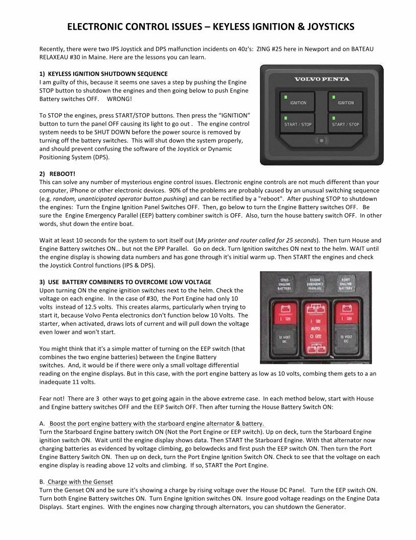
ELECTRONIC)CONTROL)ISSUES)–)KEYLESS)IGNITION)&)JOYSTICKS!!Recently,!there!were!two!IPS!Joystick!and!DPS!malfunction!incidents!on!40z's:!!ZING!#25!here!in!Newport!and!on!BATEAU!RELAXEAU!#30!in!Maine.!Here!are!the!lessons!you!can!learn.!!1)))KEYLESS)IGNITION)SHUTDOWN)SEQUENCE!I!am!guilty!of!this,!because!it!seems!one!saves!a!step!by!pushing!the!Engine!STOP!button!to!shutdown!the!engines!and!then!going!below!to!push!Engine!Battery!switches!OFF.!!!!!WRONG!!!!!To!STOP!the!engines,!press!START/STOP!buttons.!Then!press!the!“IGNITION”!button!to!turn!the!panel!OFF!causing!its!light!to!go!out!.!!!The!engine!control!system!needs!to!be!SHUT!DOWN!before!the!power!source!is!removed!by!turning!off!the!battery!switches.!!This!will!shut!down!the!system!properly,!and!should!prevent!confusing!the!software!of!the!Joystick!or!Dynamic!Positioning!System!(DPS).!!!!2))))REBOOT!!!!!This!can!solve!any!number!of!mysterious!engine!control!issues.!Electronic!engine!controls!are!not!much!different!than!your!computer,!iPhone!or!other!electronic!devices.!!90%!of!the!problems!are!probably!caused!by!an!unusual!switching!sequence!(e.g.!random,(unanticipated(operator(button(pushing)!and!can!be!rectified!by!a!"reboot".!!After!pushing!STOP!to!shutdown!the!engines:!!Turn!the!Engine!Ignition!Panel!Switches!OFF.!!Then,!go!below!to!turn!the!Engine!Battery!switches!OFF.!!!Be!sure!the!!Engine!Emergency!Parallel!(EEP)!battery!combiner!switch!is!OFF.!!Also,!turn!the!house!battery!switch!OFF.!!In!other!words,!shut!down!the!entire!boat.!!Wait!at!least!10!seconds!for!the!system!to!sort!itself!out!(My(printer(and(router(called(for(25(seconds).!!Then!turn!House!and!Engine!Battery!switches!ON…!but!not!the!EPP!Parallel.!!!Go!on!deck.!Turn!Ignition!switches!ON!next!to!the!helm.!WAIT!until!the!engine!display!is!showing!data!numbers!and!has!gone!through!it's!initial!warm!up.!Then!START!the!engines!and!check!the!Joystick!Control!functions!(IPS!&!DPS).!!3)))USE))BATTERY)COMBINERS)TO)OVERCOME)LOW)VOLTAGE!Upon!turning!ON!the!engine!ignition!switches!next!to!the!helm.!Check!the!voltage!on!each!engine.!!In!the!case!of!#30,!!the!Port!Engine!had!only!10!volts!!instead!of!12.5!volts.!!This!creates!alarms,!particularly!when!trying!to!start!it,!because!Volvo!Penta!electronics!don't!function!below!10!Volts.!!The!starter,!when!activated,!draws!lots!of!current!and!will!pull!down!the!voltage!even!lower!and!won't!start.!!You!might!think!that!it's!a!simple!matter!of!turning!on!the!EEP!switch!(that!combines!the!two!engine!batteries)!between!the!Engine!Battery!switches.!!And,!it!would!be!if!there!were!only!a!small!voltage!differential!reading!on!the!engine!displays.!But!in!this!case,!with!the!port!engine!battery!as!low!as!10!volts,!combing!them!gets!to!a!an!inadequate!11!volts.!!!!Fear!not!!!There!are!3!!other!ways!to!get!going!again!in!the!above!extreme!case.!!In!each!method!below,!start!with!House!and!Engine!battery!switches!OFF!and!the!EEP!Switch!OFF.!Then!after!turning!the!House!Battery!Switch!ON:!!A.!!!Boost!the!port!engine!battery!with!the!starboard!engine!alternator!&!battery.!!!!Turn!the!Starboard!Engine!battery!switch!ON!(Not!the!Port!Engine!or!EEP!switch).!Up!on!deck,!turn!the!Starboard!Engine!ignition!switch!ON.!!Wait!until!the!engine!display!shows!data.!Then!START!the!Starboard!Engine.!With!that!alternator!now!charging!batteries!as!evidenced!by!voltage!climbing,!go!belowdecks!and!first!push!the!EEP!switch!ON.!Then!turn!the!Port!Engine!Battery!Switch!ON.!!Then!up!on!deck,!turn!the!Port!Engine!Ignition!Switch!ON.!Check!to!see!that!the!voltage!on!each!engine!display!is!reading!above!12!volts!and!climbing.!!If!so,!START!the!Port!Engine.!!!!B.!!Charge!with!the!Genset!Turn!the!Genset!ON!and!be!sure!it's!showing!a!charge!by!rising!voltage!over!the!House!DC!Panel.!!!Turn!the!EEP!switch!ON.!Turn!both!Engine!Battery!switches!ON.!!Turn!Engine!Ignition!switches!ON.!!Insure!good!voltage!readings!on!the!Engine!Data!Displays.!!Start!engines.!!With!the!engines!now!charging!through!alternators,!you!can!shutdown!the!Generator.!!!!!!
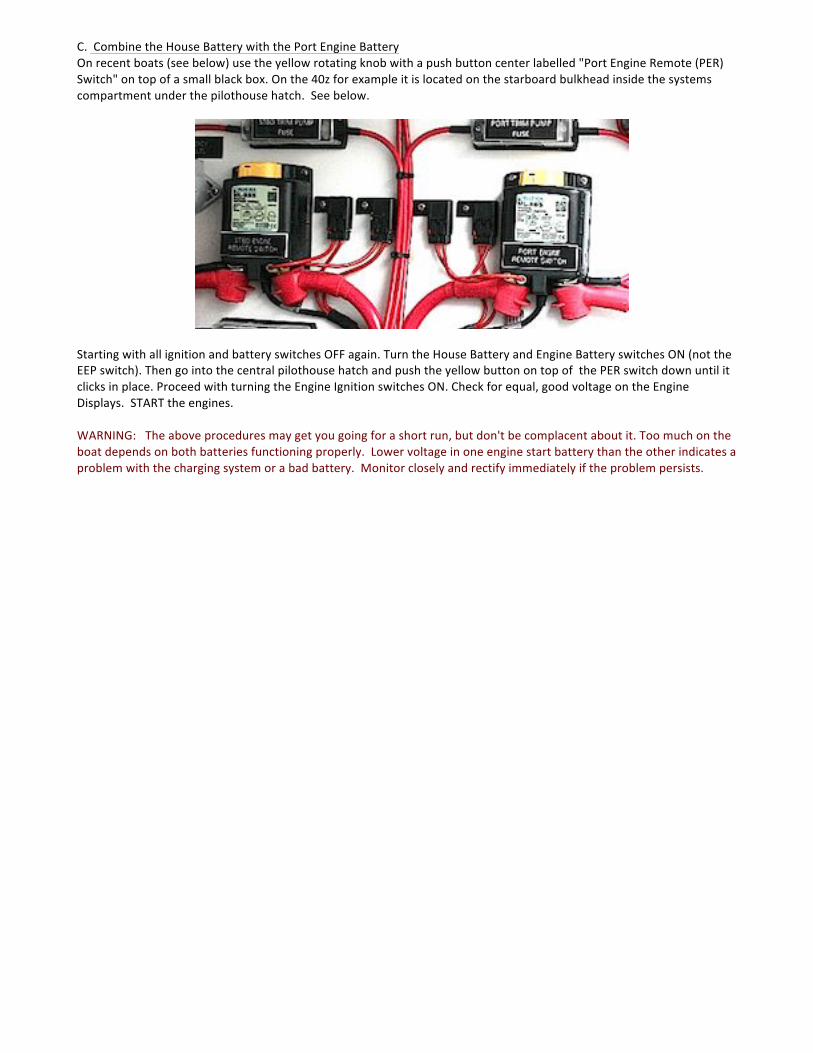
C.!!Combine!the!House!Battery!with!the!Port!Engine!Battery!On!recent!boats!(see!below)!use!the!yellow!rotating!knob!with!a!push!button!center!labelled!"Port!Engine!Remote!(PER)!Switch"!on!top!of!a!small!black!box.!On!the!40z!for!example!it!is!located!on!the!starboard!bulkhead!inside!the!systems!compartment!under!the!pilothouse!hatch.!!See!below.!!
!!Starting!with!all!ignition!and!battery!switches!OFF!again.!Turn!the!House!Battery!and!Engine!Battery!switches!ON!(not!the!EEP!switch).!Then!go!into!the!central!pilothouse!hatch!and!push!the!yellow!button!on!top!of!!the!PER!switch!down!until!it!clicks!in!place.!Proceed!with!turning!the!Engine!Ignition!switches!ON.!Check!for!equal,!good!voltage!on!the!Engine!Displays.!!START!the!engines.!!WARNING:!!!The!above!procedures!may!get!you!going!for!a!short!run,!but!don't!be!complacent!about!it.!Too!much!on!the!boat!depends!on!both!batteries!functioning!properly.!!Lower!voltage!in!one!engine!start!battery!than!the!other!indicates!a!problem!with!the!charging!system!or!a!bad!battery.!!Monitor!closely!and!rectify!immediately!if!the!problem!persists.!!!!!!
PROPULSION SYSTEM
3.9 ALARM DISPLAY When the ignition button is first pushed to the ON position, you may hear an audible alarm signal and see a “Stop Sign” appear on the Display, indicating that the diagnostic function has registered a malfunction. Please refer to Volvo Operator’s Manual chapters for detailed information about FAULTS and recommended action.
3.10 STOPPING
Put both engine controls in NEUTRAL. PUSH the Start/Stop button until the engine stops. If unsuccessful, there’s a clearly labeled “Emergency Shutdown” button in the upper middle of the engine. Make sure to push OFF the Engine Ignition button and the Engine Battery Switches on the electrical panel when leaving the boat. Engine Stop & Restart after Crash-Stop If the engine otherwise stops, the following reboot procedure for re-start must be followed. 1. Put control lever in NEUTRAL
2. Acknowledge any ALARM
3. PUSH engine ignition button until all lamps have gone out.
4. Then TURN back on the ignition system (not the engine Start) position only.
5. Acknowledge any ALARM
6. START the engine by pushing the engine START/STOP.
7. STOP the engine, TURN OFF the Ignition. Wait again until all lamps have gone out.
8. RESTART the Engine.
3.11 OPERATING PARAMETERS
While it’s good to run the engine at top speed periodically for short periods of time of 15 mnutes or so, “Max Cruising Speed” is about 200 RPM below full throttle. 3250 seems to work fine on ZING, producing a speed of 35 knots. While running, pay attention to the engine gauges on the LCD display or read on the Raymarine data bar. A significant change in oil or coolant temperature, oil pressure, or voltage should nvestigated immediately before the engine is damaged. OIL PRESSURE – Normally ______________________ except lower when idling COOLANT TEMPERATURE – Normally 185 degrees F. CHARGING – Normally 13-14 Volts when underway. Depending on hull structure and engine installation, engine and hull resonance may be greater at some speeds than others. This is normal and you will learn to pick the sweet spots. If you hear any abnormal sounds, stop the engine and inspect.
If any warning lights or buzzers activate, stop the engine immediately. Determine the cause and repair the problem before continuing to operate.
CHAPTER 3
4.1
4.2
STEERING CONTROL SYSTEM STEERING SYSTEM
The 50z has an integrated, electronically controlled power steering system which through electric motors rotate the two outer (not middle) IPS pod drives. When running, the 50z is steered as w outboards or sterndrives. Thrust of the propellers is directed more immediately and precisely from side to side through a 26° arc to steer the boat.... rather than bouncing the prop wash from a conventional straight shaft propulsion unit off a rudder. When the throttle/shift levers are put in (N) neutral and a button pushed to activate the IPS joystick: Control of the pod drives is transferred from the throttle/shift and wheel to IPS computer controlled joystick. When the joystick is activated, the steering wheel locks and no longer functions. Do not try to force it or damage may occur. Emergency Alignment If a fault occurs which prevents one or both of the propulsion units from being operated with the steering wheel, it is possible to align the faulty propulsion unit(s) so that its aimed straight ahead (and won’t act like a rudder), so as not to impair operation of either the remaining propulsion unit or the steering of the boat with the two engines. See the VPOM. Emergency Steering These controls are attached to the engine with cables, so if the electronic steering ever failed on both propulsion units, a steering method using the two engines can be employed. This is outlined on pages 60-61 of the VPOM.
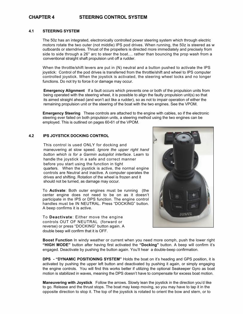
IPS JOYSTICK DOCKING CONTROL
This control is used ONLY for docking and maneuvering at slow speed. Ignore the upper right hand button which is for a Garmin autopilot interface. Learn to handle the joystick in a safe and correct manner before you start using the function in tight quarters. When the joystick is active, the normal engine controls are Neutral and inactive. A computer operates the drives and shifting. Rotation of the wheel is frozen and it should not be turned, as damage may occur.
To Activate: Both outer engines must be running (the center engine does not need to be on as it doesn’t participate in the IPS or DPS function. The engine control handles must be IN NEUTRAL. Press “DOCKING” button. A beep confirms it is active. To Deactivate : Either move the engine controls OUT OF NEUTRAL (forward or reverse) or press “DOCKING” button again. A double beep will confirm that it is OFF. Boost Function In windy weather or current when you need more oomph, push the lower right “HIGH MODE” button after having first activated the “Docking” button. A beep will confirm it’s engaged. Deactivate by pushing the button again. You’ll hear a double-beep confirmation. DPS - “DYNAMIC POSITIONING SYSTEM” Holds the boat on it’s heading and GPS position, it is activated by pushing the upper left button and deactivated by pushing it again, or simply engaging the engine controls. You will find this works better if utilizing the optional Seakeeper Gyro as boat motion is stabilized in waves, meaning the DPS doesn’t have to compensate for excess boat motion. Maneuvering with Joystick Follow the arrows. Slowly lean the joystick in the direction you’d like to go. Release and the thrust stops. The boat may keep moving, so you may have to tap it in the opposite direction to stop it. The top of the joystick is rotated to orient the bow and stern, or to
CHAPTER 4
4.3
2-E165 GPS Plotter/Radar
IPS Joysticke
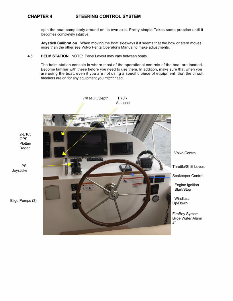
STEERING CONTROL SYSTEM spin the boat completely around on its own axis. Pretty simple Takes some practice until it becomes completely intuitive. Joystick Calibration When moving the boat sideways if it seems that the bow or stern moves more than the other see Volvo Penta Operator’s Manual to make adjustments. HELM STATION NOTE: Panel Layout may vary between boats.
The helm station console is where most of the operational controls of the boat are located. Become familiar with these before you need to use them. In addition, make sure that when you are using the boat, even if you are not using a specific piece of equipment, that the circuit breakers are on for any equipment you might need.
i70 Multi/Depth
Volvo Control Panel
Throttle/Shift Levers Seakeeper Control
Engine Ignition Start/Stop
Windlass Up/Down
FireBoy System Bilge Water Alarm 4”
CHAPTER 4
P70R Autopilot
Bilge Pumps (3)
CHAPTER 4

STEERING CONTROL SYSTEM 4.4 CONSOLE SWITCH PANEL
With the exception of the Anchor Washdown which is activated along with the “Windlass” breaker (and must have the “Water Pressure” switch ON as does the washer function of the “Wiper” switch) functions of this panel on the console are activated by turning on their respective breaker switches on the DC Electrical Panel in the main saloon. ns of the panel rocker switches are described below the corresponding switch:
Press to Sound HORN 4.5 INTERCEPTOR TRIM TAB SYSTEM The trim tab breaker on the DC panel must be ON. The percent applied Port & Starboard is displayed on the Volvo Penta EVC panel. Trim is adjusted using the 3 rocker buttons on the face of the throttle/shift control and on the side of the port handle. Either the center button on the face or the rocker switch on the port handle adjust both tabs at the same time. The 50z uses the Volvo version of the Humphries Interceptor system which has plates the move vertical at the aft outer edges of the transom. Normally tabs are adjusted simultaneously with 2 fingers. Trim tabs aren’t necessary at low speeds or high speeds other than for wind compensation. At speeds over 8 knots, trim tabs allow you to trim the boat from side to side to compensate for crew location, gear placement or to counteract wind pressure. The boat leans into the breeze. They are useful in lowering the bow for better visibility or for powering into waves without pounding. Don’t hesitate to apply maximum tabs in the 15-22 knot range. At higher speeds in smooth water, when the boat naturally runs flatter or when running downsea into the back of waves, it’s advisable to raise the trim tabs for dry running and control, allowing the bow to lift.
AUTO HORN FWD Underway 1 Blast AFT at Anchor 2 Blasts
NAV LTS FWD Underway AFT At Anchor
WIPERS
Press when Cockpit Wash Rode, Table Chain & Anchor with Fresh Water
WASHERS Read Instr Booklet.
CHAPTER 4
4.6
STEERING CONTROL SYSTEM
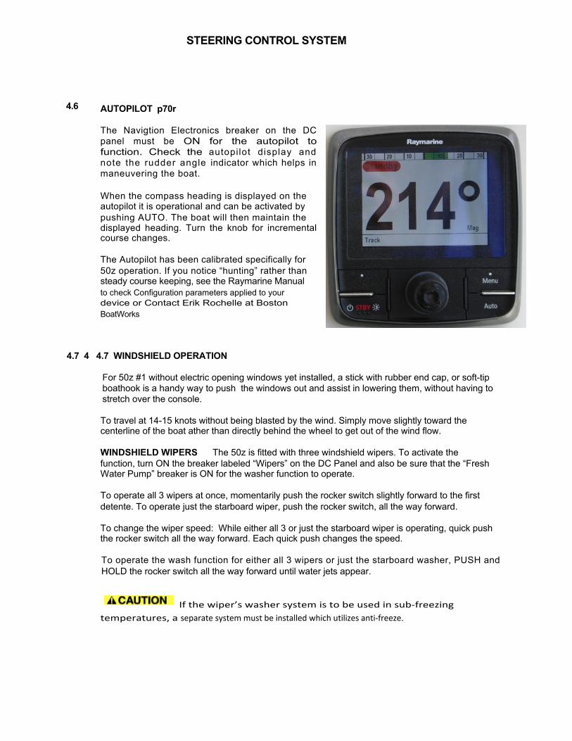
AUTOPILOT p70r The Navigtion Electronics breaker on the DC panel must be ON for the autopilot to function. Check the autopilot display and note the rudder angle indicator which helps in maneuvering the boat. When the compass heading is displayed on the autopilot it is operational and can be activated by pushing AUTO. The boat will then maintain the displayed heading. Turn the knob for incremental course changes. The Autopilot has been calibrated specifically for 50z operation. If you notice “hunting” rather than steady course keeping, see the Raymarine Manual to check Configuration parameters applied to your device or Contact Erik Rochelle at Boston BoatWorks
4.7 4 4.7 WINDSHIELD OPERATION
For 50z #1 without electric opening windows yet installed, a stick with rubber end cap, or soft-tip boathook is a handy way to push the windows out and assist in lowering them, without having to stretch over the console. To travel at 14-15 knots without being blasted by the wind. Simply move slightly toward the centerline of the boat ather than directly behind the wheel to get out of the wind flow.
WINDSHIELD WIPERS The 50z is fitted with three windshield wipers. To activate the function, turn ON the breaker labeled “Wipers” on the DC Panel and also be sure that the “Fresh Water Pump” breaker is ON for the washer function to operate. To operate all 3 wipers at once, momentarily push the rocker switch slightly forward to the first detente. To operate just the starboard wiper, push the rocker switch, all the way forward. To change the wiper speed: While either all 3 or just the starboard wiper is operating, quick push the rocker switch all the way forward. Each quick push changes the speed. To operate the wash function for either all 3 wipers or just the starboard washer, PUSH and HOLD the rocker switch all the way forward until water jets appear. If#the#wiper’s#washer#system#is#to#be#used#in#sub5freezing#temperatures,#a#separate#system#must#be#installed#which#utilizes#anti5freeze.#!
#
4.8 4.9
STEERING CONTROL SYSTEM SPOTLIGHT
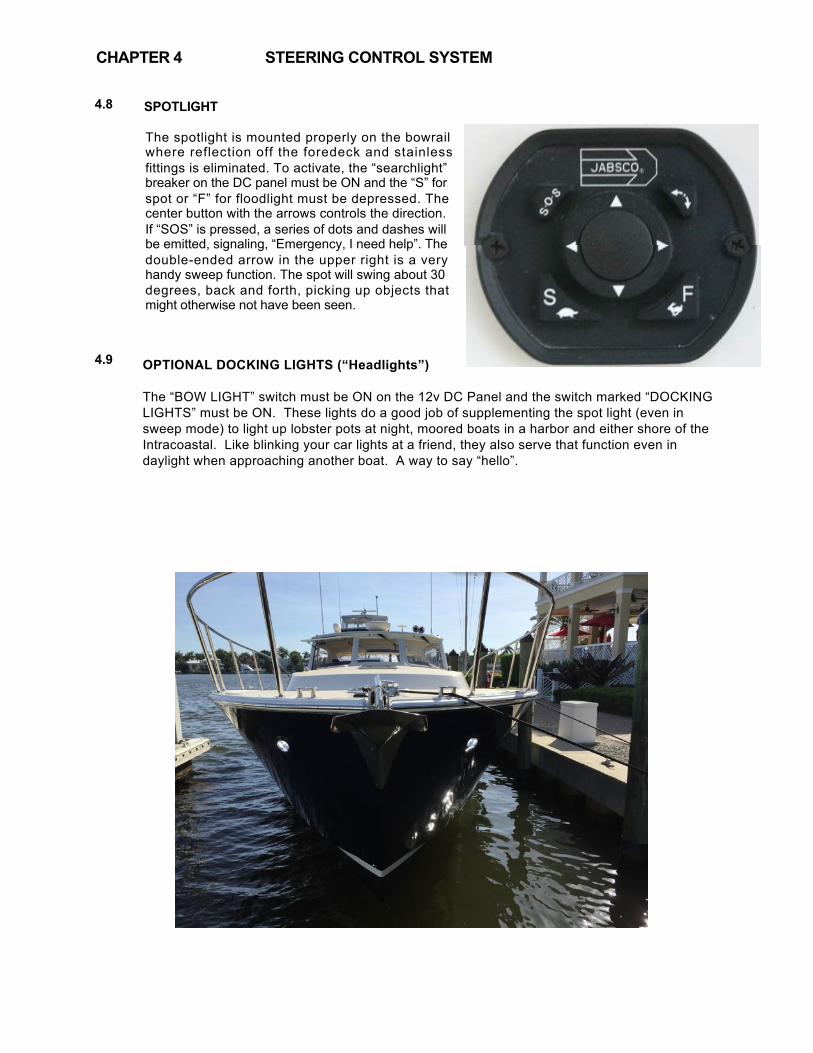
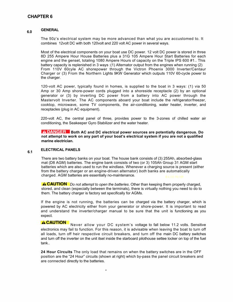
The spotlight is mounted properly on the bowrail where reflection off the foredeck and stainless fittings is eliminated. To activate, the “searchlight” breaker on the DC panel must be ON and the “S” for spot or “F” for floodlight must be depressed. The center button with the arrows controls the direction. If “SOS” is pressed, a series of dots and dashes will be emitted, signaling, “Emergency, I need help”. The double-ended arrow in the upper right is a very handy sweep function. The spot will swing about 30 degrees, back and forth, picking up objects that might otherwise not have been seen. OPTIONAL DOCKING LIGHTS (“Headlights”) The “BOW LIGHT” switch must be ON on the 12v DC Panel and the switch marked “DOCKING LIGHTS” must be ON. These lights do a good job of supplementing the spot light (even in sweep mode) to light up lobster pots at night, moored boats in a harbor and either shore of the Intracoastal. Like blinking your car lights at a friend, they also serve that function even in daylight when approaching another boat. A way to say “hello”.
CHAPTER 4

5.0
5.1
5.2
FUEL SYSTEM GENERAL
It is important to understand the fuel system aboard your boat. Diesel fuel is different than gasoline. In most respects it is safer, however precautions need to be taken to maintain the safety of your boat. Please study the safety precautions in the NMMA publication “Sportfish, Cruisers, Yachts – Owner’s Manual.” Diesel engines need to intake more fuel than they burn, and so they differ from gasoline engines in that they return excess fuel to the tank. Both feed & return of port and starboard engines are to their respective 260-gallon fuel tanks. The two fuel tanks are connected at the bottom by a “compensating” fuel line with isolating shut-off valves at both aft inboard corners.
FUEL SHUT-OFF VALVES
These valves are located on top of the fuel tanks aft and are accessed through pilothouse seat lockers. In the photo of the port tank below the valves for the port tank and the generator are shown in the open position,.
These valves should be shut down if inspecting a Racor filter, in an emergency or in case of a fire in the engine compartment.
FILLING THE TANKS Deck fills are mounted on the side decks, port & starboard, and are labeled “DIESEL.” Each one services only its respective tank, although with the connecting fuel line valve open, you will get some transfer to the opposite tank. As the tank is filled, vapor escapes the tank thru the vent.
Care should be taken while filling. Check the fuel level gauges and listen for the rise in pitch at the deck fill, as fuel reaches the top. Shut off the nozzle immediately. Do not attempt to top off” the tanks. Have an absorbent cloth handy to prevent any overboard spillage. Variations in temperature as well as trim angle could cause overflow or vent-line blockage.
CHAPTER 5

CHAPTER 5
5.3
Racor Filters for each of the engines plus the genset are your first line of defense against bad fuel and are installed on the aft face of the forward engine room bulkhead. Check these filters regularly for any accumulation of water or contamination. Water will appear as a dirty gray, cloudy substance in the clear bowl. You should be able to see thru the pink fuel in the bowl at all times. Also, you should not see bubbles passing through the filter while running. This would indicate a leak on the suction side of the fuel system.
FILTER ACCESS LID – Be sure to close fuel
shut-off valve before opening. Be careful to seal properly without pinching gasket.
CLEAR GLASS INSPECTION BOWL
WATER DRAIN PETCOCK – If water seen in bowl, hold a paper cup under the petcock and drain until clear fuel seen.
5.4 FUEL CONSUMPTION
You can learn some things from the MJM fuel efficiency chart on the next page. It’s the Horsepower Applied. Assuming similar hull designs, fuel efficiency is a function of HP applied to overcome resistance. You can see there is very little difference in fuel efficiency between the twin IPS 600 and the triple IPS 600. Lighter, narrower boats are easier to push through the water and are more efficient. Range of Efficient Operation It’s interesting to note that it doesn’t particularly matter whether you are going 19 knots or 30 knots on a 50z, nautical miles per gallon remain fairly constant. Cruising Speed Volvo Penta suggest that given suitable conditions, 200 RPM below wide open throttle, or about 3250 RPM, producing a 30 knots on the twin IPS 600 and 35 knots on the triple IPS 600. is a high cruise speed.
RACOR PRIMARY FUEL FILTERS (4)
FUEL SYSTEM

MJM FUEL CONSUMPTION LOG
DATE LOCATIONENG+HRS
HRS+since+LAST+FILL
GALS+to+FILL GPH COMMENTS

CHAPTER 5
Sour Spot The 50z seems to have a huge “Sweet Spot” and just one small “Sour Spot” to avoid at about 1600-1700 rpm where the most power is applied in overcoming resistance prior to the boat jumping up on a plane at just over 10 knots. You can see that the boat is no more efficient at that point than at 30 knots. Acceleration Tests Volvo technicians commented, “This is a Ferrari!” as I mashed the throttles forward to hit 20 knots in 5.3 seconds from a standstill. No wonder, that’s on a par with some “thunder” boats and about what it takes a Mercedes SL550 to hit 60 mph (52 knots).
CAUTION Remember that fuel level readings when underway, with the fuel pushing back in the tank where the fuel level sensor is located, could be reading ¼ tank more than what’s really there. So, when you get down to 1/3 tank, it’s time to top off.... not roll the dice on finding another fuel dock open later in the day.
FUEL SYSTEM
6.0
6.1
ELECTRICAL SYSTEM
GENERAL The 50z’s electrical system may be more advanced than what you are accustomed to. It combines 12volt DC with both 120volt and 220 volt AC power in several ways. Most of the electrical components on your boat use DC power. 12 volt DC power is stored in three 8D 255 Ampere Hour House Batteries plus a 31G 105 Ampere Hour Start Batteries for each engine and the genset, totaling 1080 Ampere Hours of capacity on the Triple IPS 600 #1.. This battery capacity is replenished in 3 ways :(1) Alternator output from the engines when running (2) From 110V 60cyle AC shorepower through the Victron Phoenix 3000 Inverter/Centaur Charger or (3) From the Northern Lights 9KW Generator which outputs 110V 60-cycle power to the charger. 120-volt AC power, typically found in homes, is supplied to the boat in 3 ways: (1) via 50 Amp or 30 Amp shore-power cords plugged into a shoreside receptacle (2) by an optional generator or (3) by inverting DC power from a battery into AC power through the Mastervolt Inverter. The AC components aboard your boat include the refrigerator/freezer, cooktop, microwave, some TV components, the air-conditioning, water heater, inverter, and receptacles (plug in AC equipment). 220-volt AC, the central panel of three, provides power to the 3-zones of chilled water air conditioning, the Seakeeper Gyro Stabilizer and the water heater.
Both AC and DC electrical power sources are potentially dangerous. Do not attempt to work on any part of your boat’s electrical system if you are not a qualified marine electrician.
ELECTRICAL PANELS
There are two battery banks on your boat. The house bank consists of (3) 255Ah, absorbed-glass mat (D8 AGM) batteries. The engine bank consists of two (or 3) 105Ah Group 31 AGM start batteries which are also used to run the windlass. Whenever a charging source is present (either from the battery charger or an engine-driven alternator) both banks are automatically charged. AGM batteries are essentially no-maintenance.
Do not attempt to open the batteries. Other than keeping them properly charged, stored, and clean (especially between the terminals), there is virtually nothing you need to do to them. The battery charger is factory set specifically for AGMs. If the engine is not running, the batteries can be charged via the battery charger, which is powered by AC electricity either from your generator or shore-power. It is important to read and understand the inverter/charger manual to be sure that the unit is functioning as you expect. Never al low your DC system’s voltage to fall below 11.2 volts. Sensitive electronics may fail to function. For this reason, it is advisable when leaving the boat to turn off all loads, turn off heir respective circuit breakers, and turn off the main DC battery switches and turn off the inverter on the unit itsel inside the starboard pilothouse settee locker on top of the fuel tank.. 24 Hour Circuits The only load that remains on when the battery switches are in the OFF position are the “24 Hour” circuits (shown at right) which by-pass the panel circuit breakers and are connected directly to the batteries.
-
CHAPTER 6
BILGE PUMP
CHAPTER 6
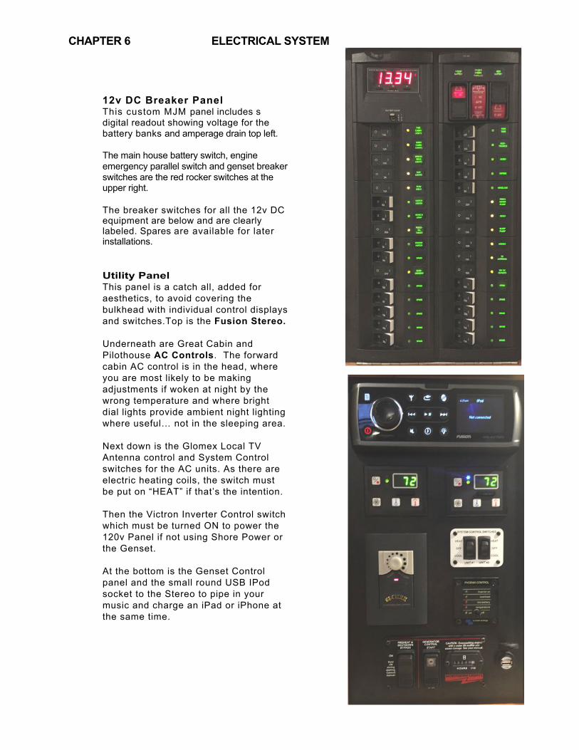
12v DC Breaker Panel This custom MJM panel includes s digital readout showing voltage for the battery banks and amperage drain top left. The main house battery switch, engine emergency parallel switch and genset breaker switches are the red rocker switches at the upper right.
The breaker switches for all the 12v DC equipment are below and are clearly labeled. Spares are available for later installations. Utility Panel This panel is a catch all, added for aesthetics, to avoid covering the bulkhead with individual control displays and switches.Top is the Fusion Stereo. Underneath are Great Cabin and Pilothouse AC Controls. The forward cabin AC control is in the head, where you are most likely to be making adjustments if woken at night by the wrong temperature and where bright dial lights provide ambient night lighting where useful… not in the sleeping area. Next down is the Glomex Local TV Antenna control and System Control switches for the AC units. As there are electric heating coils, the switch must be put on “HEAT” if that’s the intention. Then the Victron Inverter Control switch which must be turned ON to power the 120v Panel if not using Shore Power or the Genset. At the bottom is the Genset Control panel and the small round USB IPod socket to the Stereo to pipe in your music and charge an iPad or iPhone at the same time.
ELECTRICAL SYSTEM
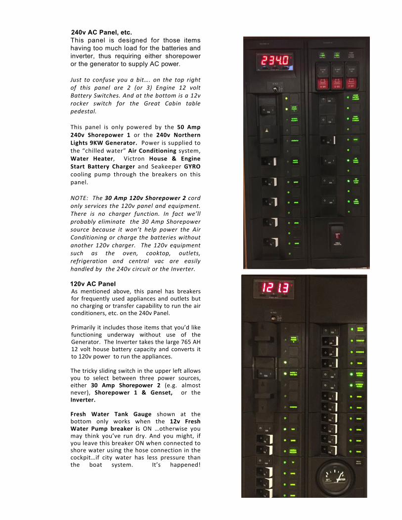
240v AC Panel, etc. This panel is designed for those items having too much load for the batteries and inverter, thus requiring either shorepower or the generator to supply AC power. #Just% to% confuse% you% a% bit….% on% the% top% right%of% this% panel% are% 2% (or% 3)% Engine% 12% volt%Battery%Switches.%And%at%the%bottom%is%a%12v%rocker% switch% for% the% Great% Cabin% table%pedestal.%#This# panel# is# only# powered# by# the# 50! Amp!240v! Shorepower! 1# or# the# 240v! Northern!Lights!9KW!Generator.! #Power#is#supplied#to#the#“chilled#water”#Air!Conditioning# system,#Water! Heater,# # Victron# House! &! Engine!Start! Battery! Charger# and# Seakeeper#GYRO!cooling# pump# through# the# breakers# on# this#panel.##
#NOTE:% %The%30#Amp#120v#Shorepower#2%cord%only%services% the%120v%panel%and%equipment.%There% is% no% charger% function.% In% fact% we’ll%probably% eliminate% % the% 30%Amp% Shorepower%%source% because% it% won’t% help% power% the% Air%Conditioning%or%charge%the%batteries%without%another% 120v% charger.% % The% 120v% equipment%such% as% the% oven,% cooktop,% outlets,%refrigeration% and% central% vac% are% easily%handled%by%%the%240v%circuit%or%the%Inverter.%#
##############################################120v AC Panel As# mentioned# above,# this# panel# has# breakers#for# frequently# used#appliances# and#outlets# but#no#charging#or#transfer#capability#to#run#the#air#conditioners,#etc.#on#the#240v#Panel.####Primarily#it#includes#those#items#that#you’d#like#functioning# underway# without# use# of# the#Generator.##The#Inverter#takes#the#large#765#AH#12# volt# house# battery# capacity# and# converts# it#to#120v#power##to#run#the#appliances.###The#tricky#sliding#switch#in#the#upper#left#allows#you# to# select# between# three# power# sources,#either! 30! Amp! Shorepower! 2# (e.g.# almost#never),# Shorepower! 1! &! Genset,# # or# the#Inverter.####Fresh! Water! Tank! Gauge# shown# at# the#bottom# only# works# when# the! 12v! Fresh!Water! Pump! breaker! is# ON# …otherwise# you#may# think# you’ve# run# dry.# And# you# might,# if#you#leave#this#breaker#ON#when#connected#to#shore#water#using#the#hose#connection#in#the#cockpit…if# city# water# has# less# pressure# than#the# boat# system.# # It’s# happened!
#

ELECTRICAL SYSTEM
Charging The HOUSE battery switch can be turned OFF when the boat is not used, and the batteries will still accept a charge from the 50 Amp 240V Shorepower 1 if HOUSE and ENGINE START CHARGER switches are ON …but not if using only the 30 Amp 120V Shorepower 2. Disconnecting shore power with INVERT left ON will cause discharge of the house battery bank. 6.2 AC SHOREPOWER CONNECTION The primary source of AC power is the 50Amp 240v Shorepower #1 cord on the starboard transom. This is operated with a Glenndinning electric reel. A gap under the door is provided to be able to run the cord out, then close the door for a better appearance.
On hull #1, you have to pull out the cord, usually needing an assist by threading a fender whip through the strap eye attached to the cord. To retract the cord, use the key fob (2 per boat) shown. Future hulls will have an IN and OUT power capability using the same control device
On the port side is found the connection for the 30A 125V Shorepower 2, shown at right next to the TV Cable hook-up. The cover lid springs back open by tapping sharply in at the bottom, SHOPEPOWER BREAKERS These are located in a box outboard over the starboard engine. If you don’t seem to be able to receive shorepower, there’s a good chance there’s been an overload of an AC circuit and one of the two breakers may have tripped. Reset by making sure both switches are ON.
HOT WATER If a shorepower receptacle is not available and you have not operated the boat recently; there won’t be any hot water from the engine’s heat exchanger. You will have to start the Generator then turn ON the hot water breaker on the 240V AC Panel, wait 15 minutes and your shower will be ready. The above Panel is also used to power the Air Conditioners.
CHAPTER 6
CHAPTER 6
6.3 NORTHERN LIGHTS 240V 9KW GENERATOR See Northern Lights Generator Operating Manual. for more information .Break-In Period Change engine oil and filter at 50 hours and again at 100 hours. Oil consumption is greater until piston rings are seated. Maintain at least a 75% load on the generator for the first 100 hours, varying the load to help seat the rings. Generator Racor Fuel Pre-Filter is located to port of the Genset and forward against the bulkhead in the engine room of the triple engine 50z and on the aft bulkhad on the twin. The Groco Rawe Water Strainer should be close by Pre-Start Checks Refer to diagrams of genset on next page. (1) Check coolant is 1” below filler cap (2) Check oil at dipstick (3) Open fuel line lever over port fuel tank. (4) Close the raw water seacock, check & clean sea strainer & reopen seacock (5) Turn ON the GENERATOR BATTERY SWITCH over the 12v DC Panel. Keep this ON whilte running or the battery charging regulator could be damaged. (6) Be sure Breaker on 120V AC Panel that reads Generator/Shorepower 1 is ON. (7) Keep OFF the GENERATOR switch on the 240V AC Panel which activates the Air Conditioning, Hot Water Heater and Gyro.You don’t want to start the generator with any load. (8) Turn OFF the Inverter toggle switch on Victron Phoenix Panel (9) PREHEAT: On the Control Panel, DEPRESS PREHEAT ON and hold for 10 Seconds (10) START: Then, depress START switch while continuing to depress PREHEAT switch. Keep pressing in for a few seconds to be sure the Generator is running. (11) RELEASE both switches. Do not crank for more than 20 seconds at a time. Allow the generator to run for about 15 seconds (12) Tun ON GENERATOR Selection switch on the 240V AC Panel to activate all circuits and be sure that the two HOUSE and ENGINE START BATTERY switches are ON. Check to see that digital meters on Panels are reading volts NOTE: if the generator starts, but no AC voltage is seen, check first that the selector switches (sliding interlocks) are ON. If so, there is a possibility the generator was overloaded and the AC breaker on the generator Control Box has tripped due to a momentary overload. Open the generator cover and reset (pull up) the AC Output Circuit Breaker TO STOP: Turn OFF GENERATOR Selector switch on the 240v AC Panel. Allow the generator to run for a 3-5 minute cool-down period. Depress STOP momentarily on the lower part of the rocker switch. Turn OFF the GENERATOR BATTERY SWITCH over the 12v DC Panel. POWER MANAGEMENT A following page shows the amperage draw of various electrical equipment on the boat as an aid to managing those loads on the generator.. The 9KW Generator is not designed to power all equipment at one time.
ELECTRICAL SYSTEM

OM773LW3 11/13
10
1. Generator Control Box 2. Air Filter 3. Fuel Filter 4. Fuel Lift Pump 5. Crankcase Vent 6. Lube Oil Fill, Top 7. Coolant Fill
Marine Generator Component Locations
8. Fuel Injector 9. Stop Solenoid10. Injection Pump 11. Lube Oil Fill, Side12. Seawater Pump����/XEH�2LO�'UDLQ14. Base frame
26. Starter27. Alternator28. Heat Exchanger End Cap29. Coolant Recovery Tank
����� %ORFN�'UDLQ 16. Fuel Inlet and Return���� 2LO�'LSVWLFN�18. Lube Oil Filter19. Control Panel Plug���� *HQHUDWRU�'DWD�3ODWH�
21. AC Circuit Breaker for AVR���� '&�&LUFXLW�%UHDNHU 23. Expansion Tank24. Wet Exhaust Elbow25. Vibration Mount
Figure 1 & 2: M773LW with PX-309K2 generator
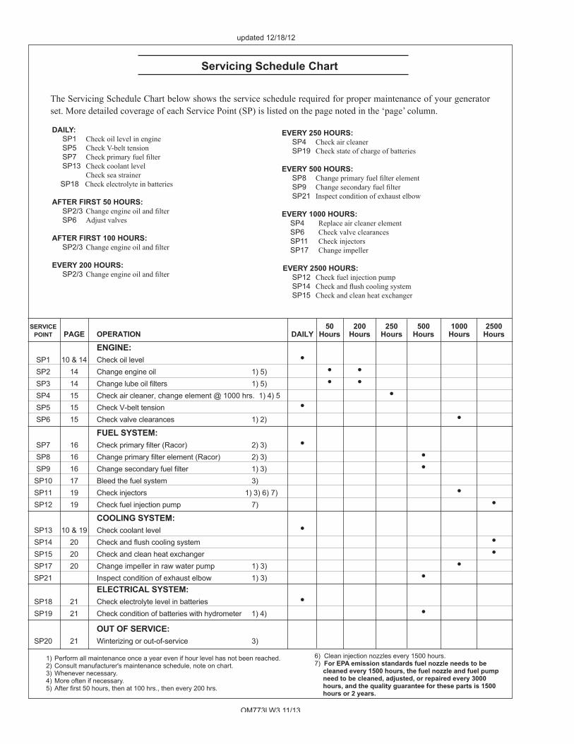
OM773LW3 11/13
16
SERVICE 50 200 250 500 1000 2500 POINT PAGE OPERATION DAILY Hours Hours Hours Hours Hours Hours
ENGINE: SP1 10 & 14 Check oil level • SP2 14 Change engine oil 1) 5) • • SP3 14� &KDQJH�OXEH�RLO�¿OWHUV� �� 5) • •� SP4 15 Check air cleaner, change element @ 1000 hrs. 1) 4) 5 •� �
SP5 15 Check V-belt tension • SP6 15 Check valve clearances 1) 2) • FUEL SYSTEM: SP7 16� &KHFN�SULPDU\�¿OWHU (Racor) 2) 3) • SP8 16� &KDQJH�SULPDU\�¿OWHU�HOHPHQW (Racor) 2) 3) • SP9 16� &KDQJH�VHFRQGDU\�IXHO�¿OWHU� ������ � � • SP10 17 Bleed the fuel system 3) SP11 19 Check injectors 1) 3) 6) 7) • SP12 19 Check fuel injection pump 7) • COOLING SYSTEM: SP13 10 & 19 Check coolant level • SP14 20� &KHFN�DQG�ÀXVK�FRROLQJ�V\VWHP� � � � • SP15 20 Check and clean heat exchanger • SP17 20 Change impeller in raw water pump 1) 3) � • SP21 Inspect condition of exhaust elbow 1) 3) • ELECTRICAL SYSTEM: SP18 21 Check electrolyte level in batteries • SP19 21 Check condition of batteries with hydrometer 1) 4) • OUT OF SERVICE: SP20 21 Winterizing or out-of-service 3)
The Servicing Schedule Chart below shows the service schedule required for proper maintenance of your generator set. More detailed coverage of each Service Point (SP) is listed on the page noted in the ‘page’ column.
DAILY: SP1 Check oil level in engine SP5 Check V-belt tension SP7 &KHFN�SULPDU\�IXHO�¿OWHU SP13 Check coolant level Check sea strainer SP18 Check electrolyte in batteries
AFTER FIRST 50 HOURS: SP2/3 &KDQJH�HQJLQH�RLO�DQG�¿OWHU SP6 Adjust valves
AFTER FIRST 100 HOURS: SP2/3 &KDQJH�HQJLQH�RLO�DQG�¿OWHU
EVERY 200 HOURS: SP2/3 &KDQJH�HQJLQH�RLO�DQG�¿OWHU
EVERY 250 HOURS: SP4 Check air cleaner SP19 Check state of charge of batteries
EVERY 500 HOURS: SP8 &KDQJH�SULPDU\�IXHO�¿OWHU�HOHPHQW SP9 &KDQJH�VHFRQGDU\�IXHO�¿OWHU SP21 Inspect condition of exhaust elbow
EVERY 1000 HOURS: SP4 Replace air cleaner element SP6 Check valve clearances SP11 Check injectors SP17 Change impeller
EVERY 2500 HOURS: SP12 Check fuel injection pump SP14 &KHFN�DQG�ÀXVK�FRROLQJ�V\VWHP SP15 Check and clean heat exchanger
1) Perform all maintenance once a year even if hour level has not been reached.2) Consult manufacturer's maintenance schedule, note on chart.3) Whenever necessary.4) More often if necessary.���$IWHU�¿UVW����KRXUV��WKHQ�DW�����KUV���WKHQ�HYHU\�����KUV�
6) Clean injection nozzles every 1500 hours.7) For EPA emission standards fuel nozzle needs to be
cleaned every 1500 hours, the fuel nozzle and fuel pump need to be cleaned, adjusted, or repaired every 3000 hours, and the quality guarantee for these parts is 1500 hours or 2 years.
Servicing Schedule Chart
updated 12/18/12
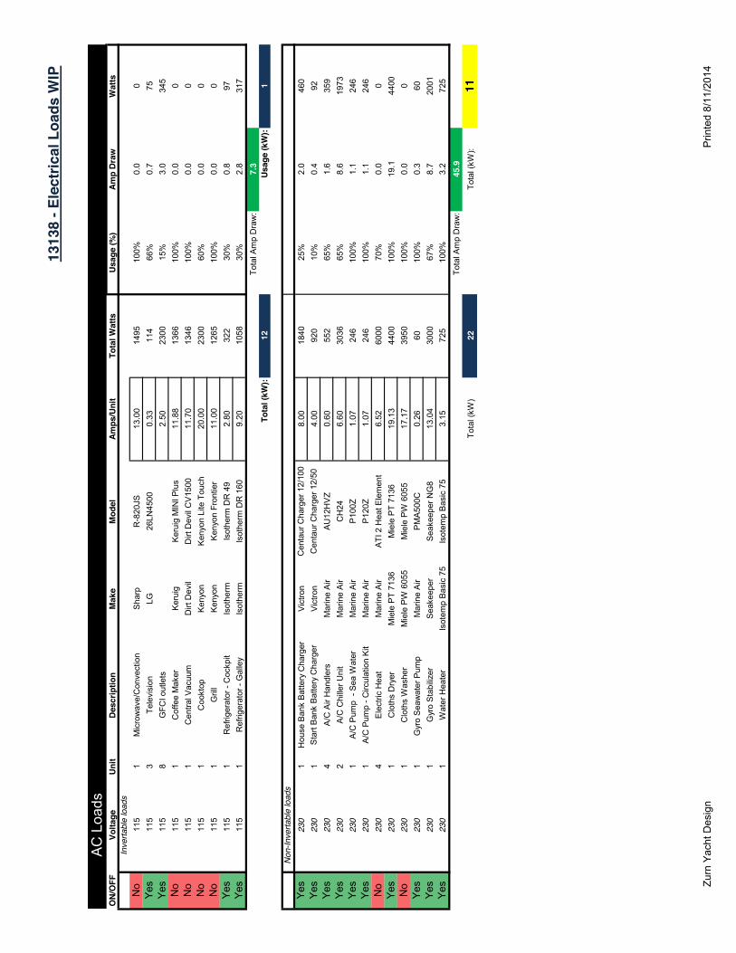
1313
8 - E
lect
rical
Loa
ds W
IP
AC
Loa
dsO
N/O
FFVo
ltage
Unit
Desc
riptio
nM
ake
Mod
elAm
ps/U
nit
Tota
l Wat
tsUs
age
(%)
Amp
Draw
Wat
tsIn
verta
ble
load
sN
o11
51
Mic
row
ave/
Con
vect
ion
Sha
rpR
-820
JS13
.00
1495
100%
0.0
0Ye
s11
53
Tele
visi
onLG
26LN
4500
0.33
114
66%
0.7
75Ye
s11
58
GFC
I out
lets
2.50
2300
15%
3.0
345
No
115
1C
offe
e M
aker
Ker
uig
Ker
uig
MIN
I Plu
s11
.88
1366
100%
0.0
0N
o11
51
Cen
tral V
acuu
mD
irt D
evil
Dirt
Dev
il C
V15
0011
.70
1346
100%
0.0
0N
o11
51
Coo
ktop
Ken
yon
Ken
yon
Lite
Tou
ch20
.00
2300
60%
0.0
0N
o11
51
Gril
lK
enyo
nK
enyo
n Fr
ontie
r11
.00
1265
100%
0.0
0Ye
s11
51
Ref
riger
ator
- C
ockp
itIs
othe
rmIs
othe
rm D
R 4
92.
8032
230
%0.
897
Yes
115
1R
efrig
erat
or -
Gal
ley
Isot
herm
Isot
herm
DR
160
9.20
1058
30%
2.8
317
Tota
l Am
p D
raw
:7.
3To
tal (
kW):
12Us
age
(kW
):1
Non
-Inve
rtabl
e lo
ads
Yes
230
1H
ouse
Ban
k B
atte
ry C
harg
erV
ictro
nC
enta
ur C
harg
er 1
2/10
08.
0018
4025
%2.
046
0Ye
s23
01
Sta
rt B
ank
Bat
tery
Cha
rger
Vic
tron
Cen
taur
Cha
rger
12/
504.
0092
010
%0.
492
Yes
230
4A
/C A
ir H
andl
ers
Mar
ine
Air
AU
12H
VZ
0.60
552
65%
1.6
359
Yes
230
2A
/C C
hille
r Uni
tM
arin
e A
irC
H24
6.60
3036
65%
8.6
1973
Yes
230
1A
/C P
ump
- S
ea W
ater
Mar
ine
Air
P10
0Z1.
0724
610
0%1.
124
6Ye
s23
01
A/C
Pum
p - C
ircul
atio
n K
itM
arin
e A
irP
120Z
1.07
246
100%
1.1
246
No
230
4E
lect
ric H
eat
Mar
ine
Air
ATI
2 H
eat E
lem
ent
6.52
6000
70%
0.0
0Ye
s23
01
Clo
ths
Dry
erM
iele
PT
7136
Mie
le P
T 71
3619
.13
4400
100%
19.1
4400
No
230
1C
loth
s W
ashe
rM
iele
PW
605
5M
iele
PW
605
517
.17
3950
100%
0.0
0Ye
s23
01
Gyr
o S
eaw
ater
Pum
p M
arin
e A
irP
MA
500C
0.26
6010
0%0.
360
Yes
230
1G
yro
Sta
biliz
erS
eake
eper
Sea
keep
er N
G8
13.0
430
0067
%8.
720
01Ye
s23
01
Wat
er H
eate
rIs
otem
p B
asic
75
Isot
emp
Bas
ic 7
53.
1572
510
0%3.
272
5To
tal A
mp
Dra
w:
45.9
Tota
l (kW
)22
Tota
l (kW
):11
Zurn
Yac
ht D
esig
nP
rinte
d 8/
11/2
014

6.4
ELECTRICAL SYSTEM VICTRON PHOENIX AUTOMATIC INVERTER/CHARGER Under normal circumstances there is no need for adjustment or operation besides switching on and off. The purpose of the inverter is to convert stored 12v DC energy in the extensive battery banks into 120v AC power to operate those accessories such as the microwave, hotplate, 120v outlets and TV, etc. that have breakers on the 120V AC Panel. This Victron unit also takes AC power from the 50Amp 240V Shorepower 1 or the Generator to charge both the house battery bank and the engine start batteries. The Phoenix inverter Control shown at right is on the Utilities Panel. INVERTING To source 120V AC (not 240v AC) power when no generator or shore-power is available: (1) Make sure the Shorepower 1/Generator breaker is OFF on the 120v AC Panel. (2) Turn ON the INVERTER breaker on the 120V AC Panel. (3) Turn ON the toggle switch at the bottom of the Phoenix Control above. DO NOT LEAVE THE INVERT SWITCH “ON” IF YOU ARE NOT
INVERTING AS THIS MAY DRAW 10-12 AMPS EVEN IF NO AC DEVICE IS TURNED ON. OR, YOU MAY END UP WITH DEAD BATTERIES (All of them if the Parallel Switch is “ON” too.) IN FACT, ALTHOUGH THIS UNIT CLAIMS TO HAVE AN AUTOMATIC SHUT OFF IF THE VOLTAGE GETS LOW TO PROTECT THE BATTERIES, IT’S BEST NOT TO COUNT ON THAT. IF YOU ARE GOING TO LEAVE THE BOAT ON A MOORING OR STORED ON LAND WITHOUT SHORE POWER, TURN OFF THE INVERTER ON THE TOP OF THE UNIT OVER THE FUEL TANK IN THE STARBOARD PILOTHOUSE SETTEE LOCKER. YOU WILL HAVE TO FEEL THE SWITCH SHOWN BELOW AS THE CLEARANCE UNDER THE DECK IS NOT GREAT.
CHAPTER 6
6.5
6.6
6.7
6.8
6.9
ELECTRICAL SYSTEM
REVERSE POLARITY
As a safety precaution, your AC panel is fitted with reverse polarity indicators. If an AC supply were wired incorrectly, either aboard your boat or shoreside, a dangerous shock situation could exist. Normally, the reverse polarity lights should not be illuminated. If they are, disconnect that source of power and alert the appropriate person.
ELECTROLYSIS & GALVANIC CORROSION
Metallic fittings that are exposed to saltwater are subject to electrolysis and galvanic corrosion. To minimize potential damage, your boat is fitted with a sacrificial zinc at the transom. This zinc is connected to the bonding system of your boat. It should be visually inspected whenever possible and replaced when 1/2 of the zinc has been eroded. Pay special attention to its condition when in new waters and marinas, as environmental conditions affect the rate of deterioration. If the zinc erodes rapidly, current meters can be used to assess possible causes and remedies. See the Volvo Penta Operator’s Manual for sacrificial anode location and inspection on the engine as well as the drives. BONDING
The bonding system of your boat connects all underwater metallic fittings to the sacrificial zinc and the boat’s negative bus bar. In order for the zinc to protect an underwater part, the connection must be clean and secure. The green wires that make up this system are not normally current carrying.
ELECTRICAL SAFETY
Please read and understand the important safety precautions included in the included NMMA publication “Sportfish, Cruisers, Yachts – Owner’s Manual” concerning electrical safety.
FUSE LOCATIONS & SPECIFICATIONS
See the attached Chart of Fuse Descriptions Type and Locations
CHAPTER 6

6.5
6.6
6.7
6.8
6.9
ELECTRICAL SYSTEM
DO NOT LEAVE THE INVERT SWITCH “ON” ON THE MICC PANEL ALONG WITH THE INVERTER/CHARGE SWITCH “ON” ON THE AC PANEL IF YOU ARE NOT INVERTING AS THIS MAY DRAW 10-12 AMPS EVEN IF NO AC DEVICE IS TURNED ON. OR, YOU MAY END UP WITH DEAD BATTERIES (All of them if the Parallel Switch is “ON” too.) Charging Push CHARGER on the MICC panel to activate the charger when SHORE POWER is applied to AC Shore 1 or when the GENERATOR is on. Then be sure the “charger/inverter” breaker is ON on AC Shore 1.
REVERSE POLARITY
As a safety precaution, your AC panel is fitted with reverse polarity indicators. If an AC supply were wired incorrectly, either aboard your boat or shoreside, a dangerous shock situation could exist. Normally, the reverse polarity lights should not be illuminated. If they are, disconnect that source of power and alert the appropriate person.
ELECTROLYSIS & GALVANIC CORROSION
Metallic fittings that are exposed to saltwater are subject to electrolysis and galvanic corrosion. To minimize potential damage, your boat is fitted with a sacrificial zinc at the transom. This zinc is connected to the bonding system of your boat. It should be visually inspected whenever possible and replaced when 1/2 of the zinc has been eroded. Pay special attention to its condition when in new waters and marinas, as environmental conditions affect the rate of deterioration. If the zinc erodes rapidly, current meters can be used to assess possible causes and remedies. See the Volvo Penta Operator’s Manual for sacrificial anode location and inspection on the engine as well as the drives. BONDING
The bonding system of your boat connects all underwater metallic fittings to the sacrificial zinc and the boat’s negative bus bar. In order for the zinc to protect an underwater part, the connection must be clean and secure. The green wires that make up this system are not normally current carrying.
ELECTRICAL SAFETY
Please read and understand the important safety precautions included in the included NMMA publication “Sportfish, Cruisers, Yachts – Owner’s Manual” concerning electrical safety.
FUSE LOCATIONS & SPECIFICATIONS
Item / Fuse Label Bilge Pump 1 Bilge Pump 2
Bilge Pump 3 Bilge Pump 1 Bilge Pump 2 Bilge Pump 3
Amplifier Stereo Memory DVD Memory
ATC High Water Alarm
- 33 -
CHAPTER 6
Emergency Parallel Supply 15 amp
5 amp 5 amp
5 amp 7.5 amp 7.5 amp 7.5 amp 40 amp 15 amp 15 amp
20 amp
Size AGC AGC
AGC ATC ATC ATC ATC ATC ATC
ATC
Fuse Block next to House Battery 1 (Stbd Settee) Fuse Block next to House Battery 1 (Stbd Settee) Fuse Block next to House Battery 1 (Stbd Settee) Fuse Block next to House Battery 1 (Stbd Settee) Fuse Block next to House Battery 1 (Stbd Settee) Fuse Block next to House Battery 1 (Stbd Settee) Fuse Block next to House Battery 1 (Stbd Settee) Fuse Block next to House Battery 1 (Stbd Settee
In the Bilge Pump Switch at the Dash In the Bilge Pump Switch at the Dash
In the Bilge Pump Switch at the Dash
Type

CHAPTER 6
Sea Fire Supply
House Switch Supply
House Remote Supply
Start 1 Switch Supply
Start 1 Remote Supply
Start 2 Switch Supply
Start 2 Remote Supply
Generator Switch Supply
Generator Remote Supply
Combiner 1 Negative
Combiner 2 Negative
Engine Room Blower Engine Room Blower
VacuFlush ATC - Plastic Fuse AGC - Glass Fuse
Item / Fuse Label Horn Fuse
Main Panel Fuse
Start Battery 1 Fuse House Battery 1 Fuse Start Battery 2 Fuse
House Battery 2 Fuse House Bank Fuse
House Parallel Fuse Inverter Charger Fuse
Inverter Fuse Inverter Charger Fuse
Inverter Fuse
10 amp 15 amp
5 amp
15 amp 10 amp
15 amp
10 amp
15 amp
5 amp 15 amp
15 amp
15 amp 15 amp 3 amp
Size Type 40 amps 100 amps ANL
200 amps ANL 200 amps ANL 200 amps ANL 200 amps ANL 250 amps ANL 250 amps ANL 250 amps ANL 250 amps ANL 250 amps ANL 250 amps ANL
- 34 -
House Bus at the Black Fuse Board (Stbd Settee
Hatch) Remote Battery Switch next to House Battery 2
(Port Settee Hatch) Remote Battery Switch next to House Battery 2
(Port Settee Hatch) Remote Battery Switch next to Start Battery 1
(Stbd Settee Hatch)
Remote Battery Switch next to Start Battery 2
(Stbd Settee Hatch) Remote Battery Switch next to Start Battery 2
(Stbd Settee Hatch) Remote Battery Switch next to Generator Battery
(Port Settee Hatch) Remote Battery Switch next to Generator Battery
(Port Settee Hatch) Battery Combiner next to Air Conditioner Control
(Bridge Deck Hatch) Battery Combiner next to Air Conditioner Control
(Bridge Deck Hatch) Behind the dash next to the ignition relay Behind the dash next to the ignition relay Top of the Holding Tank (Port Aft Hatch)
Location Port Settee Hatch (next to the horn compressor)
Stbd Settee Hatch (fuse board)
Stbd Settee Hatch (behind start battery) Stbd Settee Hatch ( next to the house battery)
Stbd Settee Hatch (behind start battery) Port Settee Hatch (next to the house battery) Port Settee Hatch (next to the house battery)
Bridge Deck Hatch (fwd wall off the hatch) Stbd Settee Hatch (fuse board)
Stbd Settee Hatch ( next to the house battery) Stbd Settee Hatch (fuse board)
Stbd Settee Hatch ( next to the house battery)
ELECTRICAL SYSTEM
AGC
AGC
AGC
AGC
AGC Remote Battery Switch next to Start Battery 1 (Stbd Settee Hatch)
AGC
AGC
AGC
AGC
AGC
AGC
AGC AGC AGC
ANL
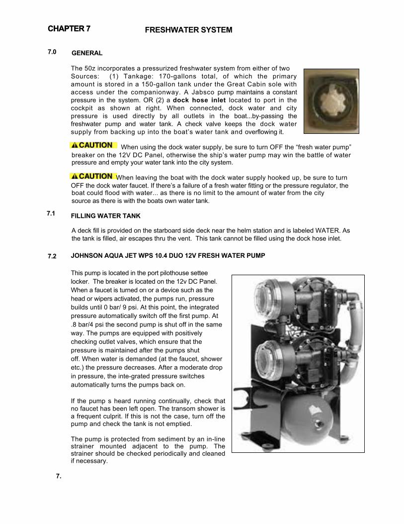
7.0
7.1
7.2
FRESHWATER SYSTEM
GENERAL The 50z incorporates a pressurized freshwater system from either of two Sources: (1) Tankage: 170-gallons total, of which the primary amount is stored in a 150-gallon tank under the Great Cabin sole with access under the companionway. A Jabsco pump maintains a constant pressure in the system. OR (2) a dock hose inlet located to port in the cockpit as shown at right. When connected, dock water and city pressure is used directly by all outlets in the boat...by-passing the freshwater pump and water tank. A check valve keeps the dock water supply from backing up into the boat’s water tank and overflowing it.
When using the dock water supply, be sure to turn OFF the “fresh water pump” breaker on the 12V DC Panel, otherwise the ship’s water pump may win the battle of water pressure and empty your water tank into the city system.
When leaving the boat with the dock water supply hooked up, be sure to turn OFF the dock water faucet. If there’s a failure of a fresh water fitting or the pressure regulator, the boat could flood with water... as there is no limit to the amount of water from the city source as there is with the boats own water tank. FILLING WATER TANK
A deck fill is provided on the starboard side deck near the helm station and is labeled WATER. As the tank is filled, air escapes thru the vent. This tank cannot be filled using the dock hose inlet. JOHNSON AQUA JET WPS 10.4 DUO 12V FRESH WATER PUMP This pump is located in the port pilothouse settee locker. The breaker is located on the 12v DC Panel. When a faucet is turned on or a device such as the head or wipers activated, the pumps run, pressure builds until 0 bar/ 9 psi. At this point, the integrated pressure automatically switch off the first pump. At .8 bar/4 psi the second pump is shut off in the same way. The pumps are equipped with positively checking outlet valves, which ensure that the pressure is maintained after the pumps shut off. When water is demanded (at the faucet, shower etc.) the pressure decreases. After a moderate drop in pressure, the inte-grated pressure switches automatically turns the pumps back on. If the pump s heard running continually, check that no faucet has been left open. The transom shower is a frequent culprit. If this is not the case, turn off the pump and check the tank is not emptied. The pump is protected from sediment by an in-line strainer mounted adjacent to the pump. The strainer should be checked periodically and cleaned if necessary.
7.
CHAPTER 7 CHAPTER 7

7.3 7.4
FRESHWATER SYSTEM
INDEL ISOTEMP 20 GALLON HOT WATER TANK Water in the 20-gallon hot water tank is located in the port pilothouse settee locker. Water in the tank is heated in one of 2 ways (1) whenever the engine is operating or (2) when the engine is not running, by turning on the “Water Heater” breaker on the 240v AC Panel. It is part of the freshwater system and does not need to be filled separately. There is virtually no need for maintenance, but the connections at the tank should be visually inspected occasionally. The coolant lines from the engine to the tank have shut-off valves. These need to be OPEN in order for the engine to heat the water in the tank. For service, or in case or a ruptured line, these valves can be closed to stop this water loop. GENERAL ECOLOGY SEAGULL WATER PURIFIER
[See also Seagull owner’s manual] The galley is fitted with the best available water purifier in the world that probably produces better water than obtained in supermarket bottled water. It is used on 85 airlines.and by the military where the water supply is contaminated by chemical warfare agents. This purifier has a cartridge (in stainless pressure vessel under sink) that should be replaced annually or when either reduced water flow indicates that it has become plugged with sediment or the taste is odd.
It is best to clear the pressure water system of any winter anti-freeze before
running water through the cartridge. The filter is rated for 1000 gallons, which is approximately 15 water tanks’ worth. Replace it at least once per year.
CHAPTER 7
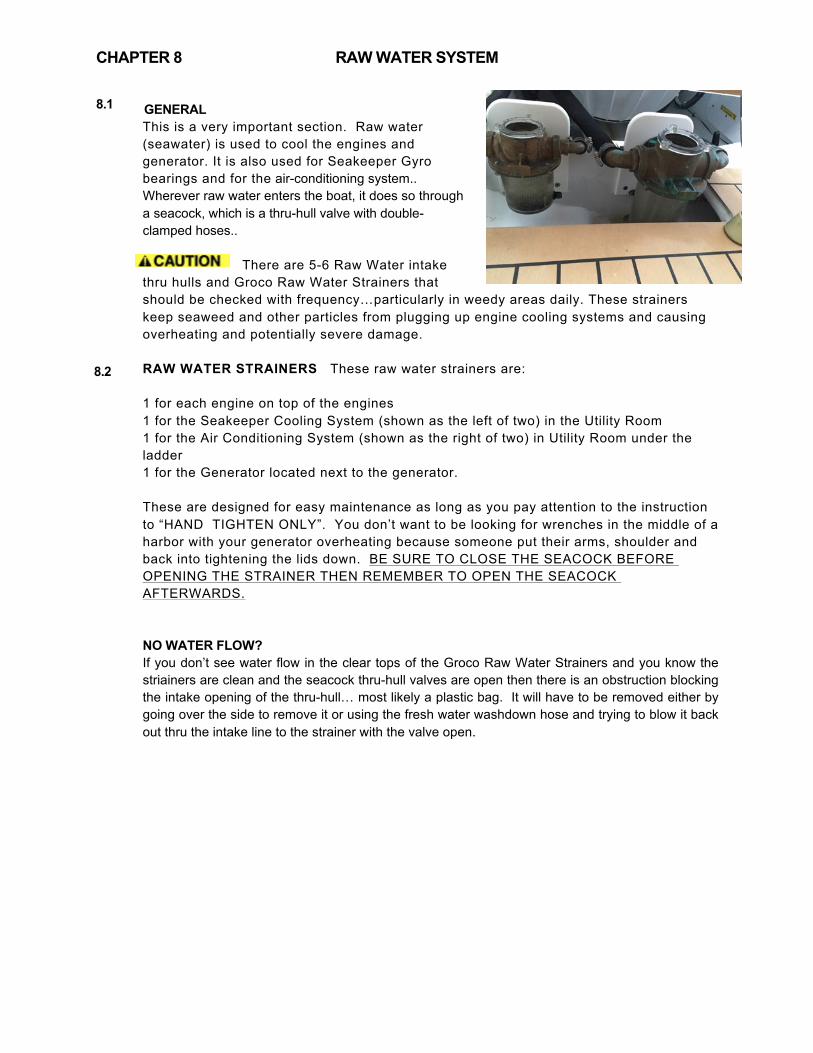
8.1
8.2
GENERAL This is a very important section. Raw water (seawater) is used to cool the engines and generator. It is also used for Seakeeper Gyro bearings and for the air-conditioning system.. Wherever raw water enters the boat, it does so through a seacock, which is a thru-hull valve with double-clamped hoses..
There are 5-6 Raw Water intake
thru hulls and Groco Raw Water Strainers that should be checked with frequency…particularly in weedy areas daily. These strainers keep seaweed and other particles from plugging up engine cooling systems and causing overheating and potentially severe damage. RAW WATER STRAINERS These raw water strainers are: 1 for each engine on top of the engines 1 for the Seakeeper Cooling System (shown as the left of two) in the Utility Room 1 for the Air Conditioning System (shown as the right of two) in Utility Room under the ladder 1 for the Generator located next to the generator. These are designed for easy maintenance as long as you pay attention to the instruction to “HAND TIGHTEN ONLY”. You don’t want to be looking for wrenches in the middle of a harbor with your generator overheating because someone put their arms, shoulder and back into tightening the lids down. BE SURE TO CLOSE THE SEACOCK BEFORE OPENING THE STRAINER THEN REMEMBER TO OPEN THE SEACOCK AFTERWARDS. NO WATER FLOW? If you don’t see water flow in the clear tops of the Groco Raw Water Strainers and you know the striainers are clean and the seacock thru-hull valves are open then there is an obstruction blocking the intake opening of the thru-hull… most likely a plastic bag. It will have to be removed either by going over the side to remove it or using the fresh water washdown hose and trying to blow it back out thru the intake line to the strainer with the valve open.
CHAPTER 8 RAW WATER SYSTEM
9.1
9.2
9.3
9.4
GRAY WATER SYSTEM
GENERAL
Gray water is liquid that can legally be pumped overboard, generally from sink drains, shower drains, and bilges. Your boat also directs deck run-off to of all gray water through common drains (port & starboard) in the transom.
GRAY WATER SUMPS
There are two gray water sump boxes aboard your boat located (a) in the storage compartment under the hatch in the cabin sole between the shower and head and (b) below the bottom companionway step. These collect water from the shower drain, the dish locker drain, and the air- conditioning condenser. The sump pump switch on the DC panel operates a bilge pump with normal float switch to empty the tank when any of the above systems are in use. Periodically, the cover of the tank should be removed and the contents/strainers cleaned.
BILGE PUMPS There are three automatic electric bilge pumps fitted on your boat, plus an emergency manual pump. The manual bilge pump is located under the port piloting seat and is operated by opening the plastic cover, inserting the handle, and pumping up and down. There is a noticeable difference when the bilge has run dry. This pump is most often used as a back-up system to the 3 automatic pumps. Its capacity is 15 gal/min.
The automatic pumps are located forward of the engine and under the companionway steps, are wired directly to the house battery bank. This means that even when the main battery switches are OFF, the bilge pump can continue to function properly. A three-way switch controls the pumps. When held in the manual position, the pump will work regardless of whether there is water in the bilge or not. In the OFF position, the pump will not turn on. In the AUTO position operates if the water level rises. If water is detected, the pump continues to run until the water is gone. Generally, the pump should be left in the AUTO position.
COMMON DRAINS
To eliminate unnecessary thru hull penetrations in the topsides, a common drain system is utilized on both port and starboard sides. Make sure, especially when air-conditioning is running, that the outlets for these drains, located in the transom under the swim platform, are not obstructed. Items that drain into the common drains include: hatch gutters, galley and head sinks, deck drains, sump tank and air-conditioning discharge.
CHAPTER 9

CHAPTER 10
Please see the operating manuals provided with your 50z both in hard copy and CD. A list of which is on the following page.
10.1 SEAKEEPER 9 GYROSTABILIZER GENERAL
The Seakeeper Gyro is a 900 lb sphere that spins at up to 9000 RPM to create a near-immovable force. It is anchored to a reinforced structure over the bottom of the boat to withstand the torque applied to the hull by waves, thus dramatically reducing the boat’s tendency to roll. The Seakeeper must be run from the Generator or the 50 AMP 240V AC Shorepower.
START SEAKEEPER Before starting the Seakeeper, be sure to check the raw water strainter under the ladder to the utility room to be sure that the cooling water intake to the Gyro is not blocked. With the 240V AC Panel activated by either the Generator or Shorepower 1: Turn ON the GYRO Breaker. Then to activate the Seakeeper Control Panel on the Dash, turn ON the GYRO on the 12V DC Panel. Then PUSH the lefthandmost button of the Seakeeper control box on the helm console so the button symbol turns from red to green. The bar then indicates progress of the gyro spooling up. It takes about 35 minutes to reach the point where the 2nd buttom from the left can be pushed to activate the gyro, ACTIVATE SEAKEEPER Seakeeper is activated, once the status bar has disappeared by pushing the 2nd button from the left. You will then see the lock symbol unlock and the gyro start to swivel on the control panel screen. DE-ACTIVATE When underway, you can DEACTIVE the Seakeeper by pushing this button again and you will see the Gyro image stop rotating. You can go back and forth between “GYRO ON” and “GYRO OFF” by continuing to push this 2nd button…it takes maybe 10-15 seconds to respond to either action.
TURNING OFF
Push the lefthandmost button on the Seakeeper control panel. It’s a good idea to do this as early as possible on the way into port to give the unit at least a half hour and preferrably more to spool down. The power to the Seakeeper should remain ON at the panels below, The reason is that it is important to allow the 240v cooling pump to keep on functioning to cool the bearings when at higher RPMs.
CHECK SEAKEEPER STATUS CAUTION Be sure to check the raw water strainer for the Seakeeper for blockage before/after each use to be sure it’s clear, otherwise the temperatures for the bearings could rise high enough to cause damage. To check for the temperature of bearings and the RPM, the procedure is as follows:
With the Seakeeper Control Panel ON, push the 5th button (Gears) – then the 4th button (tools) then the 4th button (right arrow) again. Fill in the Code 4442 when prompted, then hit button 5 (left arrow). Keep hitting button 4 (right arrow) to display: RPM, Upper & Lower Bearing Temp and Drive Temp. Hit button 5 (left arrow) to return.
SYSTEMS & EQUIPMENT

CHAPTER 10
10.2 ANCHOR WINDLASS Refer to the manual for specific operating instructions. The windlass draws power from the engine start battery. It is therefore advisable to only use the windlass when the engine is running, and to allow time for the battery to recharge after windlass use. Never try to move the boat forward with the windlass- it is sized to retrieve the anchoring gear, not to pull the boat forward. If the windlass bogs down, use the boat’s engine to move directly over the anchor. If the anchor has become firmly lodged, use the boat’s engine to free it, then commence retrieval with the windlass. Note: always let the windlass come to a stop before reversing direction; otherwise, the windlass fuse/breaker may blow. To use the windlass, the engine start battery switch and house battery switch must both be ON and the windlass breaker on the panel must be ON.
To avoid chafe on the anchor rode when anchoring, it is advisable to remove the rode from the anchor chute by grabbing it below the roller, then pulling it up directly from the anchor, feeding it through a bow chock to a mooring cleat. Never rely on the windlass itself to hold the anchor rode- the chain stopper or a cleat should be used to take the load so as to avoid damaging the windlass’ gears. When not using the windlass or when underway, we recommend securing the anchor and chain with the anchor hook/lever.This prevents the anchor and rode from inadvertently running free underway and fouling the props. ANCHOR WASHDOWN A spray nozzle to wash saltwater or mud from the anchor rode and chain is located under the anchor roller. It is activated, when raising the anchor, by depressing a rocker switch on the switch panel on the piloting console.
10.3 PILOTHOUSE CURTAINS Do not use any chemicals or brushes to clean, only mild soap. If the curtains become scratched a mild polishing compound (a white cream polishing compound supplied by Strataglass similar to what is used on Awlgrip) can be applied by hand to remove them. Test a small, unobtrusive area first. Always store curtains rolled together and not folded (to avoid creases).
10.4 PRIVACY/SUNSCREEN CURTAINS (OPTION) Fine white mesh allows you to see out but makes it difficult to see in as demonstrated below. When installed at night, these curtains convert the Pilothouse to an additional stateroom. The 8 Curtain set comes rolled up in its own carry bag. The aft and windshield curtains attach by Velcro inside. The two large side curtains are attached inside by shock cord, which enables deployment while the standard StrataGlass curtains are rolled up. The advantage of inside curtains is that they don’t become dirty over time or require storage wet from dew when departing in the morning. Rolling of the curtain is best accomplished by laying first an end of the large side curtains over the top of the pilothouse table so that the end closest to you is just about touching the floor – allowing the rest to bunch up on the port settee or outboard side of the table. Continue to lay all 8 sections on top of each other with the ends together. Then roll all sections up together and place in the storage tube
SYSTEMS & EQUIPMENT
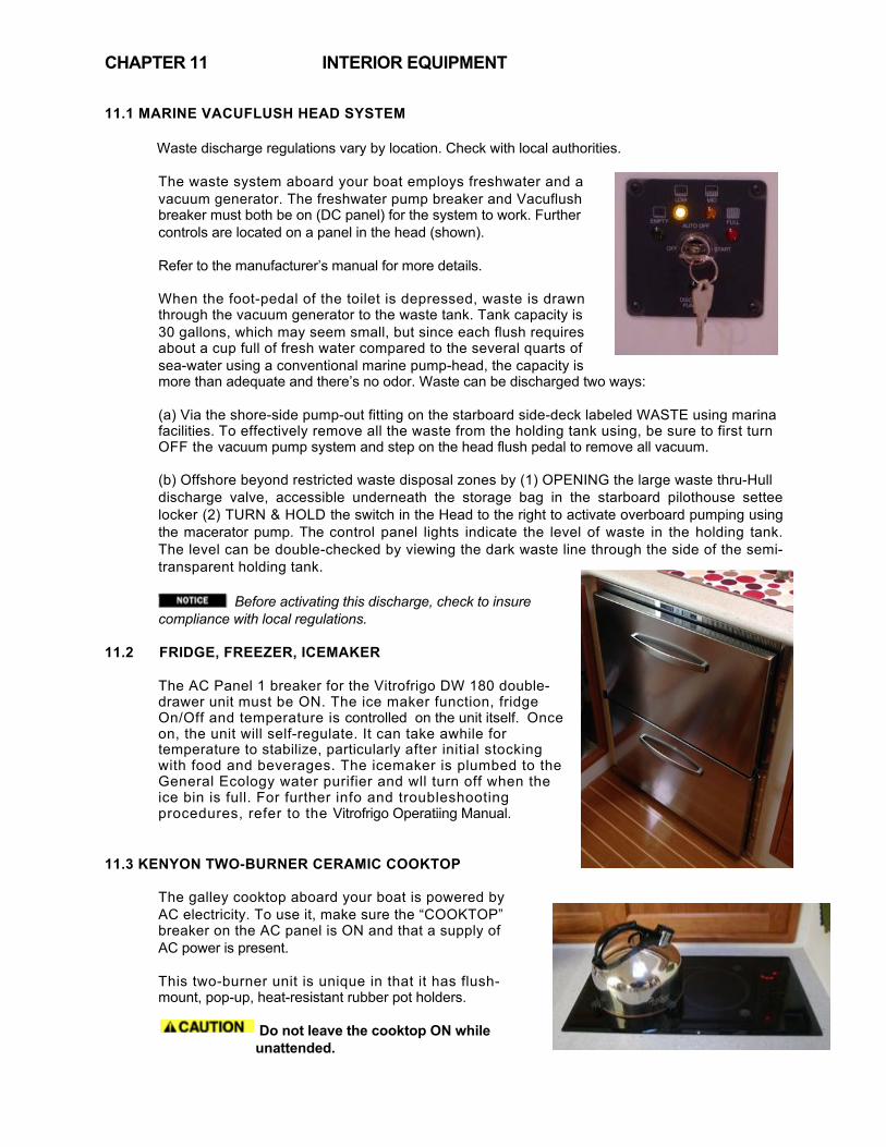
CHAPTER 11
11.1 MARINE VACUFLUSH HEAD SYSTEM
Waste discharge regulations vary by location. Check with local authorities.
The waste system aboard your boat employs freshwater and a vacuum generator. The freshwater pump breaker and Vacuflush breaker must both be on (DC panel) for the system to work. Further controls are located on a panel in the head (shown). Refer to the manufacturer’s manual for more details. When the foot-pedal of the toilet is depressed, waste is drawn through the vacuum generator to the waste tank. Tank capacity is 30 gallons, which may seem small, but since each flush requires about a cup full of fresh water compared to the several quarts of sea-water using a conventional marine pump-head, the capacity is more than adequate and there’s no odor. Waste can be discharged two ways: (a) Via the shore-side pump-out fitting on the starboard side-deck labeled WASTE using marina facilities. To effectively remove all the waste from the holding tank using, be sure to first turn OFF the vacuum pump system and step on the head flush pedal to remove all vacuum. (b) Offshore beyond restricted waste disposal zones by (1) OPENING the large waste thru-Hull discharge valve, accessible underneath the storage bag in the starboard pilothouse settee locker (2) TURN & HOLD the switch in the Head to the right to activate overboard pumping using the macerator pump. The control panel lights indicate the level of waste in the holding tank. The level can be double-checked by viewing the dark waste line through the side of the semi-transparent holding tank. Before activating this discharge, check to insure compliance with local regulations.
11.2 FRIDGE, FREEZER, ICEMAKER
The AC Panel 1 breaker for the Vitrofrigo DW 180 double-drawer unit must be ON. The ice maker function, fridge On/Off and temperature is controlled on the unit itself. Once on, the unit will self-regulate. It can take awhile for temperature to stabilize, particularly after initial stocking with food and beverages. The icemaker is plumbed to the General Ecology water purifier and wll turn off when the ice bin is full. For further info and troubleshooting procedures, refer to the Vitrofrigo Operatiing Manual.
11.3 KENYON TWO-BURNER CERAMIC COOKTOP
The galley cooktop aboard your boat is powered by AC electricity. To use it, make sure the “COOKTOP” breaker on the AC panel is ON and that a supply of AC power is present. This two-burner unit is unique in that it has flush- mount, pop-up, heat-resistant rubber pot holders.
Do not leave the cooktop ON while unattended.
INTERIOR EQUIPMENT

CHAPTER 11
11.4 SHARP DOUBLE GRILL CONVECTION OVEN
This unit offers several cooking modes which maybe operated without shorepower by utilizing the inverter for AC power and turning ON the MICROWAVE switch on the 120V AC Panel. Please refer to the Sharp Users Manual for operating instructions and precautions. The manual is stored nside the oven when the boat i s initially delivered.
11.5 MARINE-AIR AIR-CONDITIONING UNITS
This chilled water air conditioning system consists of chillera under the ladder to the utility room, airhandlers installed throughout, freshwater piping connecting the chiller to the airhandlers, and the seawater system.
In cooling mode, warm cabin air is drawn (or blown) across the airhandler coil by the blower. Heat is removed from the air as it passes across the coil. The cooled air is then blown back into the cabin. The heat from the cabin air is transferred to the fresh water circulating through the coil. The warmed water is pumped back to the chiller. The water is circulated through the chiller's evaporator where the heat is transferred to the refrigerant in the evaporator coil, thus cooling the "chilled" water. The "heated" refrigerant gas is returned to the compressor, compressed, and then circulated through the outer tube in the chiller's condenser coil. Seawater is circulating through the condenser via the seawater system. The heat is transferred from the refrigerant to the seawater and pumped overboard taking the original cabin air heat with it. The circulating, "chilled" water (not seawater) is then pumped back through the piping to the airhandlers in a continuous loop as the cycle repeats. The vessel is heated with electric heat. On the 50z you have to select HEAT or COOL, depending on which mode you prefer on System Control Switches shown at right.
Verify that the Air Conditioner seacock, located below the utility room ladder is open and thet the raw water strainer is clear. Tune ON all 3 Air Condtioner breakers on the 240V AC panel. Turn ON the Passport I/0 Display and select temperature. The forward cabin control is located in the head, where it’s light won’t keep you awake and it is where you are likely to be if woken at night by need for a temperature change. To adjust fan speed range so that the lowest setting “1” is hardly noticeable and high-speed setting “6” is sufficient: Push the Fan Control button until “P1” shows. Then Press Star to select “P2”, Press Up or Down Arrow until reading “65” Press Star to get to “P3” Press Up or Down Arrow until reading “40” The A/C system uses raw water, much like the engine, for heat exchange. There is an intake seacock, strainer & pump located in the Systems Room under the pilothouse. These should be checked frequently, and are the first things to check if the unit fails to deliver cold air.
INTERIOR EQUIPMENT

11.6 FUSION 700 PLAYER (Optional)
This multi-media unit operates on DC power. The STEREO breaker on the DC panel must be ON. See the instruction manual for operating details. It takes some getting used to. This unit is also the CD and DVD player, with a single slot and there’s a USB plug located on the panel where you can plug in your iPad or iPhone and charge it as well
11.7 SIRIUS SATELLITE RADIO ACTIVATION (Optional)
To activate Sirius Satellite Radio services you will need to access the serial number. See instructions in the Fusion Manual:
11.8 LED TELEVISIONS (Optional) TV receivers operate with 120V AC Power. Turn ON the “TV” Breaker on the AC Panel. Click the “Menu” button on the TV remote and select Source. Video signals maybe acquired from the Fusion DVD player, from a dockside cable TV outlet, from a Glomax local TV antenna (this antenna must be turned on for reception), or from the optional KVH satellite dish system.

CHAPTER 12
ITEM ENGINE
Oil Level Daily Check Engine Oil Filters
Air Cleaner Check ea. 50 hrs Drive-Belt Tension/Wear Check ea. 14 days Remove Zincs & Check Every 100 hrs
Check Valve Clearances Turbo Charger Every 200 hrs
Mounts Annually Coolant Level Daily Check
Drive Unit Oil Level Daily Check Valve Clearance & Injectors Check
Oil in Bilge Daily Engine Area & Leakage Daily
FUEL SYSTEM
Tanks/Valves/Connections Monthly Racor Primary Fuel Filter Daily Secondary Engine Filter
Fuel System When necessary Injectors Check ea. 500 hrs
Fuel Injection Pump Check
GENERATOR Oil Level Daily or ea 8 hrs.
Oil Ea. 100 hrs. Fuel Filter/Water Separator Daily or ea 8 hrs.
Fuel Filter Ea 100 hrs. Engine Hoses Weekly
Exhaust System Weekly
RAW WATER COOLINGSYSTEM
Heat Exchanger Every 2400 hrs Sea Water Filter Check ea. 14 days Cooling System Every 500 hrs.
FRESH WATER SYSTEM Water Tank Annually
Water Pump Strainer Monthly or Less Hoses & Valves Daily
Seagull Purifier Cartridge Annually -
ACTION
Change after 1st 50 hrs, then ea. 200 hrs
Clean if necessary and replace oil. Tension if necessary. At each oil change or 6 months Clean Blower Tighten Add if necessary. Do not overfill! Add if necessary. Do not overfill! 500 hrs. Identify source, Correct, Clean-Up Identify source, Correct, Clean-Up
Inspect for leaks and ease of valve operation Clean if necessary. Change ea. 200 hrs. Change ea. 200 hrs. or when necessary. Bleed Every 2400 hrs.
Check and add if necessary Check for contamination and clean Check Drain and replace filter ea 100 hrs. Check that they are hard & tightly secured Inspect for leaks. Check ant-siphon.
Check & clean Clean screen & bowl if necessary Check & Flush Flush clean & disinfect. Remove & clean Observe leaks or note recycling of pressure system Replace cartridge more frequently if reduced flow
12.1 SCHEDULE Refer to the following chart for an approximation of routine maintenance actions. Refer to the Volvo-Penta IPS Operator’ Manual, page 62-64, for more complete instructions on each item.
Perform all maintenance once a year even if hour levels have not been reached. Some of the items you may choose to leave to professionals, but many you can do yourself. In particular, it is a good idea to have a certified mechanic perform check-ups from time to time on the engine, generator, and any other key equipment installed onboard. Volvo Penta & Northern Lights
engines are assumed – check your manuals if your brands differ.
ROUTINE MAINTENANCE
FREQUENCY
Replace after 1st 50 hrs, then ea. 200 hrs
Check after 1st 50 then ea. 500 hrs
Change ( 1st time after 50 hrs.)

CHAPTER 12
GRAY WATER SYSTEM
Sumps Annually Automatic Bilge Pumps (3) Daily Check
Manual Bilge Pump Monthly Bilge Area Daily Check
ELECTRICAL SYSTEM
Batteries Monthly House & Engine Batteries Daily Check
Connections Annually Transom & Drive Zincs Quarterly
MISCELLANEOUS
Trim Tabs Daily Trim Tabs Monthly
Bottom Paint Monthly or Less
12.2 FLUID -
In Main Cabin Floor Hatch & Systems Room Test with manual switch Check operation Inspect and clean as needed
Remove Lids, check for loose cables, clean Voltage Inspect all connections Inspect and replace if necessary
Check Operation Inspect & remove barnacles for proper operation
Remove growth with diver to sustain performance
Engine lube oil – 5.3 gallons 15W40 (SAE viscosity) Transmission oil - 3.7 gallons of VP 1141634 (API GL5 SAE 75W/90) Synthetic. Coolant - Mix 40% “Volvo Penta Coolant” with 60% distilled or deionized water.
ROUTINE MAINTENANCE
CHAPTER 13
13.1 START OF SEASON
[commissioning]
13.2 END OF SEASON
Most facilities will not require additional information before hauling the boat with a Travelift or crane, but if this is the case, use the included Lifting Diagram Figure 14.10. The end of the season is a good time to have the bottom power-washed and to check all thruhulls and seacocks for growth. Careful inspection of all underwater hardware at this point may avoid a potential problem in the future. This is also a good time to check the zincs of the boat and replace as necessary. If the boat is to be stored in a place where the ambient temperature may fall below the freezing point, it must be winterized. Plumbing lines need to be emptied and anti-freeze added where applicable. Consult also the engine operator’s manual.
SEASONAL MAINTENANCE

14.1 - EMERGENCY DIAGRAM
Manual Bilge Pump
Seakeeper Raw Water Intake Thruhull
Fuel Shut-Off Valve (over tanks) Gen Set Raw Water & Separator Discharge Thruhulls Battery Disconnects
Electric Bilge Pump
First Aid Kit
AC Unit Raw Water Intake Thruhull
Fuel Shut-Off Valve (over tanks)
Electric Bilge Pump Electric Bilge Pump
Fireboy Battery Disconnects

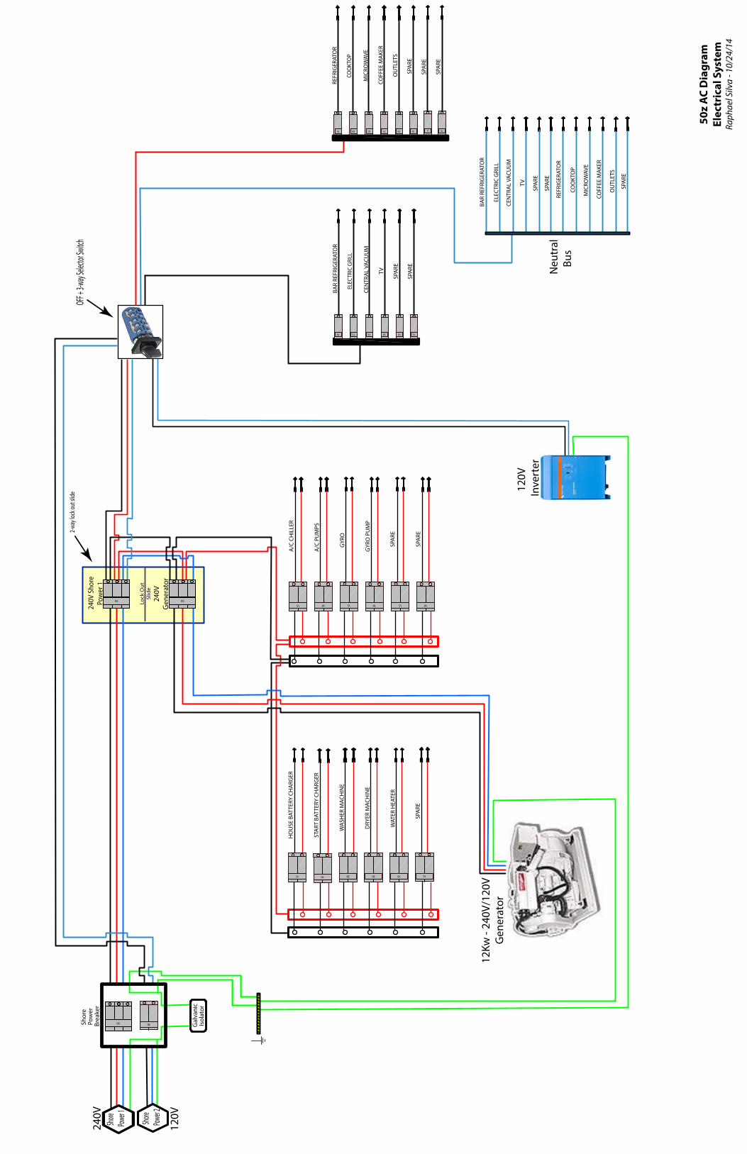
Gal
vani
cIs
olat
or
REFR
IGER
ATO
R
COO
KTO
P
OU
TLET
S
SPAR
E
COFF
EE M
AKER
MIC
ROW
AVE
50z
AC D
iagr
amEl
ectr
ical
Sys
tem
Raph
ael S
ilva
- 10/
24/1
4
Sho
re P
ower
Brea
ker
50
A/C
PUM
PS
10
GYR
O
15
GYR
O P
UM
P
10
A/C
CHIL
LER
15
HO
USE
BAT
TERY
CH
ARG
ER
STAR
T BA
TTER
Y CH
ARG
ER
15
Shore
Pow
er 1
Shore
Pow
er 2
240
VG
ener
ator
240V
Sho
re P
ower
1
10 15
WAT
ER H
EATE
R
30
DRY
ER M
ACH
INE
20
WAS
HER
MAC
HIN
E
SPAR
ESP
ARE
SPAR
E
15 101010 15
BAR
REFR
IGER
ATO
R
ELEC
TRIC
GRI
LL
CEN
TRAL
VAC
UU
M
TV
SPAR
E
SPAR
E
15
5
SPAR
E
SPAR
E
1520 201515 20
REFR
IGER
ATO
R
COO
KTO
P
MIC
ROW
AVE
COFF
EE M
AKER
OU
TLET
S
SPAR
E
10
15 10
30
BAR
REFR
IGER
ATO
R
ELEC
TRIC
GRI
LL
CEN
TRAL
VAC
UU
M
SPAR
E
SPAR
E
TV
10
OFF +
3-way S
electo
r Switch
2-way
lock
out s
lide
Lock
Out
S
lide
5050
120
VIn
vert
er
12Kw
- 24
0V/1
20V
Gen
erat
or
240V
120V
Neu
tral
Bu
s

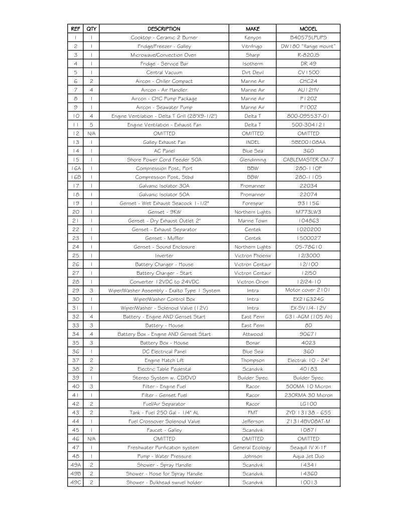
REFREFREFREF QTYQTYQTYQTY DESCRIPTIONDESCRIPTIONDESCRIPTIONDESCRIPTION MAKEMAKEMAKEMAKE MODELMODELMODELMODEL
1 1 Cooktop - Ceramic 2 Burner Kenyon B40575LPUPS
2 1 Fridge/Freezer - Galley Vitrifrigo DW180 “flange mount”
3 1 Microwave/Convection Oven Sharp R-820JS
4 1 Fridge - Service Bar Isotherm DR 49
5 1 Central Vacuum Dirt Devil CV1500
6 2 Aircon - Chiller Compact Marine Air CHC24
7 4 Aircon - Air Handler Marine Air AU12HV
8 1 Aircon - CHC Pump Package Marine Air P120Z
9 1 Aircon - Seawater Pump Marine Air P100Z
10 4 Engine Ventilation - Delta T Grill (28"X9-1/2") Delta T 800-095537-01
11 5 Engine Ventilation - Exhaust Fan Delta T 500-304121
12 N/A OMITTED OMITTED OMITTED
13 1 Galley Exhaust Fan INDEL SBE00108AA
14 1 AC Panel Blue Sea 360
15 1 Shore Power Cord Feeder 50A Glendinning CABLEMASTER CM-7
16A 1 Compression Post, Port BBW 280-110P
16B 1 Compression Post, Stbd BBW 280-110S
17 1 Galvanic Isolator 30A Promariner 22034
18 1 Galvanic Isolator 50A Promariner 22074
19 1 Genset - Wet Exhaust Seacock 1-1/2" Forespar 931156
20 1 Genset - 9KW Northern Lights M773LW3
21 1 Genset - Dry Exhaust Outlet 2" Marine Town 104863
22 1 Genset - Exhaust Separator Centek 1020200
23 1 Genset - Muffler Centek 1500027
24 1 Genset - Sound Enclosure Northern Lights 05-78610
25 1 Inverter Victron Phoenix 12/3000
26 1 Battery Charger - House Victron Centaur 12/100
27 1 Battery Charger - Start Victron Centaur 12/50
28 1 Converter 12VDC to 24VDC Victron Orion 12/24-10
29 3 Wiper/Washer Assembly - Exalto Type 1 System Imtra Motor cover 2101
30 1 Wiper/Washer Control Box Imtra EX216324G
31 1 Wiper/Washer - Solenoid Valve (12V) Imtra EX-SV1/4-12V
32 4 Battery - Engine AND Genset Start East Penn G31-AGM (105 Ah)
33 3 Battery - House East Penn 8D
34 4 Battery Box - Engine AND Genset Start Attwood 90671
35 3 Battery Box - House Bonar 4023
36 1 DC Electrical Panel Blue Sea 360
37 2 Engine Hatch Lift Thompson Electrak 10 - 24"
38 2 Electric Table Pedestal Scandvik 40183
39 1 Stereo System w. CD/DVD Builder Spec Builder Spec
40 3 Filter - Engine Fuel Racor 500MA 10 Micron
41 1 Filter - Genset Fuel Racor 230RMA 30 Micron
42 2 Fuel/Air Separator Racor LG100
43 2 Tank - Fuel 250 Gal - 1/4" AL FMT ZYD 13138 - 655
44 1 Fuel Crossover Solenoid Valve Jefferson Z1314BV08AT-M
45 1 Faucet - Galley Scandvik 10871
46 N/A OMITTED OMITTED OMITTED
47 1 Freshwater Purification system General Ecology Seagull IV X-1F
48 1 Pump - Water Pressure Johnson Aqua Jet Duo
49A 2 Shower - Spray Handle Scandvik 14341
49B 2 Shower - Hose for Spray Handle Scandvik 14360
49C 2 Shower - Bulkhead swivel holder Scandvik 10013


REFREFREFREF QTYQTYQTYQTY DESCRIPTIONDESCRIPTIONDESCRIPTIONDESCRIPTION MAKEMAKEMAKEMAKE MODELMODELMODELMODEL
50 2 Shower - Mixer Scandvik 16201
51 1 Tank - Fresh Water 150 Gal. Builder Spec ZYD 13138 - 665
52 1 Water Heater - 20 Gal. Isotherm Basic 75
53 1 Bilge Strainer Groco BS-1500
54 3 Pump - Bilge Auto Rule 1100
55 1 Pump - Bilge Manual Bosworth GH-M500D (M5V)
56 2 Pump - Sump w/tank Rule 98
57 1 Sink - Galley Scandvik 10220
58 N/A OMITTED OMITTED OMITTED
59 2 Thru-Hull - Bilge Water Auto 1-1/8" Marine Town Builder Spec
60 1 Thru-Hull - Bilge Water Manual 1-1/2" Marine Town Builder Spec
61 1 Seacock - Black Water Discharge Sealand Builder Spec
62 2 Toilet Sealand Vacuflush 506+
63 1 Tank - Black Water Holding 30 Gal. Builder Spec ZYD 13138 - 685
64 2 Vacuum Generator Sealand S-Series Low Profile
65 1 Pump - Black Water Discharge Sealand T-Series
66 1 Filter - Black Water Tank Vent Sealand Sanigard 5/8"
67 1 Seacock - Air Conditioning Intake 1-1/4" Forespar Builder Spec
68 1 Thru-Hull - Air Conditioning Discharge 1" Marine Town Builder Spec
69 1 Seacock - Genset Intake 3/4" Forespar 931143
70 1 Seawater Strainer - Air Conditioning Groco ARG-1250 P
71 1 Seawater Strainer - Genset Groco ARG-755 P
72 1 Air Horn - Compressor Kahlenberg P449-18
73 1 Air Horn - Tank Kahlenberg P449-3
74 4 Fire Extinguisher - Portable Kidde KID-466628
75 1 Fire Suppression System - Engine room Sea-fire FD-450A
76 1 Automatic Engine Shutdown (6 circuit) Sea-fire ESRS V
77 2 Trim Interceptors Volvo Penta IS 900
78 1 Gyro Stabilizer Seakeeper 9
79 1 Active Corrosion Protection Volvo Penta ACP
80 1 Seacock - Gyro Intake 3/4" Forespar Builder Spec
81 1 Seawater Strainer - Gyro Groco ARG-755 P
82 1 Pump - Gyro Cooling Water Marine Air PML500C
83 1 Thru-Hull - Gyro Cooling Water Discharge 3/4" Marine Town Builder Spec
84 1 Black Water Discharge Vented Loop Forespar MF 840
85* 1 Built-In Box Freezer Isotherm BI 53 F
86* 1 Washing Machine Miele PW 6055
87* 1 Clothes Dryer Miele PT 7136
88* 1 Electric Grill Kenyon B70050
89* 1 Sink - Wet Bar Scandvik 10242
90* 1 Faucet - Wet Bar Scandvik 10622
91 1 RESERVED RESERVED RESERVED
92* 1 Sealift - Hydraulic Pump SeaLift TBD
93 2 Faucet - Head Scandvik 10476
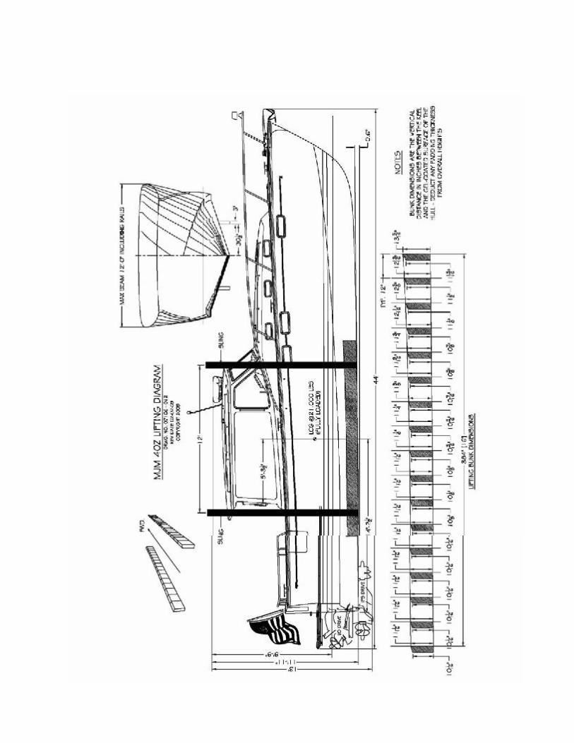
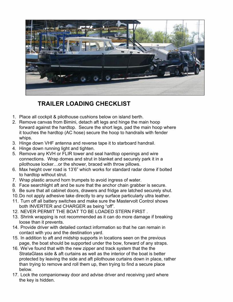
FIRGFIGUREF
TRAILER LOADING CHECKLIST
1. Place all cockpit & pilothouse cushions below on island berth. 2. Remove canvas from Bimini, detach aft legs and hinge the main hoop
forward against the hardtop. Secure the short legs, pad the main hoop where it touches the hardtop (AC hose) secure the hoop to handrails with fender whips.
3. Hinge down VHF antenna and reverse tape it to starboard handrail. 4. Hinge down running light and tighten. 5. Remove any KVH or FLIR tower and seal hardtop openings and wire
connections. Wrap domes and strut in blanket and securely park it in a pilothouse locker…or the shower, braced with throw pillows.
6. Max height over road is 13’6” which works for standard radar dome if bolted to hardtop without strut.
7. Wrap plastic around horn trumpets to avoid ingress of water. 8. Face searchlight aft and be sure that the anchor chain grabber is secure. 9. Be sure that all cabinet doors, drawers and fridge are latched securely shut. 10. Do not apply adhesive take directly to any surface particularly ultra leather. 11. Turn off all battery switches and make sure the Mastervolt Control shows
both INVERTER and CHARGER as being “off”. 12. NEVER PERMIT THE BOAT TO BE LOADED STERN FIRST . 13. Shrink wrapping is not recommended as it can do more damage if breaking
loose than it prevents. 14. Provide driver with detailed contact information so that he can remain in
contact with you and the destination yard. 15. In addition to aft and midship supports in locations seen on the previous
page, the boat should be supported under the bow, forward of any straps. 16. We’ve found that with the new zipper and track system that the the
StrataGlass side & aft curtains as well as the interior of the boat is better protected by leaving the side and aft pilothouse curtains down in place, rather than trying to remove and roll them up, then trying to find a secure place below.
17. Lock the companionway door and advise driver and receiving yard where the key is hidden.
CHAPTER 15 BOSTON BOATWORKS LIMITED WARRANTY
Manufacturer’s Sole and Limited Warranty for Pleasure craft
A. General. This document sets forth the sole and limited warranty, which Boston BoatWorks (“The Manufacturer”) is giving you in connection with the “Vessel” which you are acquiring. It is the only warranty being given by the Manufacturer and should be reviewed carefully together with manuals and other instructional material provided by the Manufacturer before you take delivery of the Vessel.
B. Basic Warranty. The Manufacturer warrants that the Vessel (except for Excluded items described below and when Properly Used, will be free of defects in material and workmanship for a period of twelve (12) months from delivery of the Vessel to you by an Authorized Dealer. If you sell the Vessel during this period, your buyer may receive the benefit of the balance of the warranty by agreeing to be bound by its terms.
C. Extended Warranty for Structure. In addition to the foregoing warranty, the Manufacturer warrants that the stringer systems, structural bulkheads and composite laminates of the Vessel (except for Excluded items) and when the Vessel is Properly Used, will be free of defects in material and workmanship for a period of five (5) years from delivery date by an Authorized Dealer. This warranty may be transferred to your buyer in the same manner as the Basic Warranty.
D. Extended Warranty Against Osmotic Blistering. In addition to the foregoing warranties, the Manufacturer warrants that any gelcoat surfaces of the Vessel below the waterline will not blister when the Vessel is Properly Used for a period of ten (10) years from delivery date by an Authorized Dealer. This warranty may be transferred to your buyer on the same manner as the Basic Warranty.
E. Dealers. The name and address of Authorized Dealers is available from the Manufacturer. The Manufacturer does not authorize the Dealer, or any other person, to assume for the Manufacturer any
liability in connection herewith or any liability or expense incurred in the repairing of its products other than those expressly authorized by the Manufacturer in writing.
F. Excluded Items. The Manufacturer gives no warranty as to:
a. Paints, varnishes, gelcoat (except where included in paragraph D above)a, exterior wood, vinyl, fabrics, glass, chrome plating or anodized or other finishes or surface coatings because of the varying quality of these items manufactured by others and the effect resulting from different climactic and use conditions
b. Engines, mechanical equipment, pumps, batteries, heating, plumbing, refrigeration, electronic components, masts, or other components manufactured by other than the Manufacturer, or the cost of removal or re-installment of the part and disassembly, or reassembly of the unit of which it is a component.
c. All items not installed by the Manufacturer or altered after their installation, and items installed or altered by Authorized Dealers.
d. Other than upon first being delivered, leaks in or around hatches, companionways, deck hardware or other leaks which are above the waterline.
e. Damage to the Vessel (including, but not limited to, wet core) caused by leakage around decks, hardware or other accessories attached to, or incorporated into, the Vessel.
f. Speed, fuel consumption or other performance characteristics, because they are estimated and not guaranteed.
G. Proper Use. The warranties contained herein are expressly conditioned upon your Proper Use of the
Vessel. This means that you must use the Vessel solely as a pleasure craft (no commercial use) and operate it as directed in and after reviewing the Manuals provided by the original equipment manufacturer and the

Manufacturer, and perform maintenance to the Vessel as recommended in the Manuals and as required by periodic inspections by an Authorized Dealer or Service Center.
H. Warranty Claims. To make a claim under this warranty you must do the following
a. Report the defect to the Manufacturer or Authorized Dealer within thirty (30) days of discovering it, and when possible prior to incurring any expense, identifying the Vessel and submitting photographs (email digital preferred).
b. Make the Vessel available for inspection by the Manufacturer or Authorized Dealer when requested.
c. Make the vessel available for repairs, if required, by the Manufacturer or Authorized Dealer. d. Major components, such as engines, generators, air-conditioners, electronics, appliances for
example are warranted by the manufacturer of the component. They have authorized service dealers in most major boating markets. The Manufacturer or Dealer will identify such service dealers upon request.
I. Repair or Replacement. The manufacturer shall perform its obligations under this warranty by, at it option, repairing or replacing (at Manufacturer’s expense) the defective part or component. Parts or components replaced will become the property of the Manufacturer. The replacement of parts o components will not extend the warranty but the replacement parts and components will be covered for the balance of the warranty period. You shall be responsible for returning the Vessel to Manufacturer at its plant or at a designated marina in the State of Massachusetts or to such other repair facility that the Manufacturer shall designate, at your sole expense.
J. Specification Changes. The manufacturer reserves the right to make changes in design, equipment, layout or construction without notice or being obligated to incorporate such changes in previous products.
K. Registration Cards. The Manufacturer recommends that you immediately fill out and return the Warranty Registration Card for the Vessel. The information contained on this card will enable the Manufacturer to more quickly process any warranty claims and to comply with the Federal Boating Safety Act. Should you sell the Vessel, the Manufacturer recommends that your buyer also fill or a Warranty Registration Card.
L. Exclusion of Implied Warranties. The foregoing warranty is intended to be in lieu of all other warranties, express or implied. In part, due to the hazardous, life-threatening environment, capable of overwhelming vessels of any size, that the Vessel will operate in, THE MANUFACTURER OR ITS DEALER DISCLAIMS ALL IMPLIED WARRRANTIES INCLUDING WARANTIES OF MERCHANTABILITY AND FITNESS FOR A PARTICULAR USE. In some jurisdictions, the Manufacturer is prohibited from excluding or limiting implied warranties. In those jurisdictions, the Manufacturer expressly limits any implied warranties to the greatest extent and to the shortest duration allowed by law.
M. Limitation of Damages. THE MANUFACTUER OR ITS DEALER DISCLAIMS ANY LIABILITY TO YOU FOR INCIDENTAL, CONSEQUENTIAL OR INDIRECT DAMAGES TO YOU, including loss of use, loss of revenue, travel expenses, transportation charges, food or lodging charges or loss of personal property. In some jurisdictions, the Manufacturer is prohibited from excluding or limiting implied warranties. In those jurisdictions, the Manufacturer expressly limits any implied warranties to the greatest extent and to the shortest duration allowed by law.
N. Whole Agreement. This warranty is the sole warranty given to you by the Manufacturer. Authorized Dealers are not authorized to make changes to this warranty. Any questions about the warranty should be directed to the Manufacturer. If you do bring a claim against the Manufacturer that is related to the Vessel, you must bring it in the Courts for the State of Massachusetts.

BOSTON BOATWORKS Pre-Approval for Warranty
Please Fax Claim to: (617) 561-9222 Date_______________________ Boat Model_______________Boat Name_________________________Hull #______________
Dealer__________________________Contact Person__________________________________
Phones___________________Fax___________________ Email_________________________
Description of Problem: _________________________________________________________
_____________________________________________________________________________
_____________________________________________________________________________
_____________________________________________________________________________
Description of Resolution: _______________________________________________________________________
_____________________________________________________________________________
_____________________________________________________________________________
_____________________________________________________________________________
____________________________________________________________________________
_____________________________________________________________________________
Estimated Completion Date: ________________ Labor Rate $ _____________________ Total Materials Cost $ _______________________
Total Labor Hours _________________ Total Estimated Cost $ _______________________
AMOUNT APPROVED: $_____________________ APPROVED BY:_________________
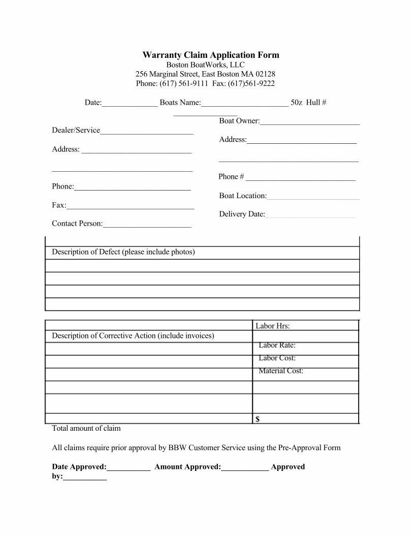
Warranty Claim Application Form Boston BoatWorks, LLC
256 Marginal Street, East Boston MA 02128 Phone: (617) 561-9111 Fax: (617)561-9222
Date:______________ Boats Name:______________________ 50z Hull #
________________
Dealer/Service_______________________
Address: ____________________________
___________________________________
Phone:_____________________________
Fax:_______________________________
Contact Person:______________________
Description of Defect (please include photos)
Description of Corrective Action (include invoices) Labor Rate: Labor Cost: Material Cost:
Total amount of claim
All claims require prior approval by BBW Customer Service using the Pre-Approval Form
Date Approved:___________ Amount Approved:____________ Approved by:___________
Boat Owner:_________________________
Address:____________________________
___________________________________
Phone # ____________________________
Boat Location:_______________________
Delivery Date:_______________________
Labor Hrs:
$
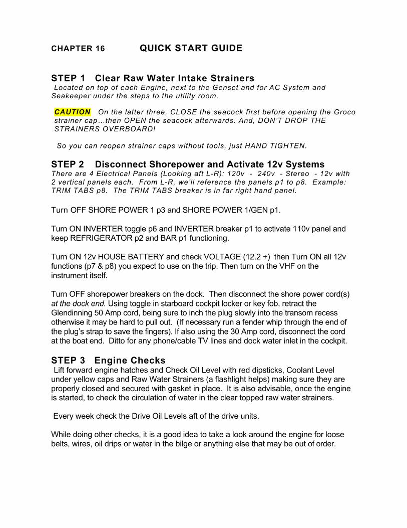
CHAPTER 16 QUICK START GUIDE STEP 1 Clear Raw Water Intake Strainers Located on top of each Engine, next to the Genset and for AC System and
Seakeeper under the steps to the utility room. CAUTION On the latter three, CLOSE the seacock first before opening the Groco strainer cap…then OPEN the seacock afterwards. And, DON’T DROP THE STRAINERS OVERBOARD! So you can reopen strainer caps without tools, just HAND TIGHTEN.
STEP 2 Disconnect Shorepower and Activate 12v Systems There are 4 Electrical Panels (Looking aft L-R): 120v - 240v - Stereo - 12v with 2 vertical panels each. From L-R, we’ll reference the panels p1 to p8. Example: TRIM TABS p8. The TRIM TABS breaker is in far right hand panel. Turn OFF SHORE POWER 1 p3 and SHORE POWER 1/GEN p1.
Turn ON INVERTER toggle p6 and INVERTER breaker p1 to activate 110v panel and keep REFRIGERATOR p2 and BAR p1 functioning. Turn ON 12v HOUSE BATTERY and check VOLTAGE (12.2 +) then Turn ON all 12v functions (p7 & p8) you expect to use on the trip. Then turn on the VHF on the instrument itself. Turn OFF shorepower breakers on the dock. Then disconnect the shore power cord(s) at the dock end. Using toggle in starboard cockpit locker or key fob, retract the Glendinning 50 Amp cord, being sure to inch the plug slowly into the transom recess otherwise it may be hard to pull out. (If necessary run a fender whip through the end of the plug’s strap to save the fingers). If also using the 30 Amp cord, disconnect the cord at the boat end. Ditto for any phone/cable TV lines and dock water inlet in the cockpit. STEP 3 Engine Checks Lift forward engine hatches and Check Oil Level with red dipsticks, Coolant Level
under yellow caps and Raw Water Strainers (a flashlight helps) making sure they are properly closed and secured with gasket in place. It is also advisable, once the engine is started, to check the circulation of water in the clear topped raw water strainers.
Every week check the Drive Oil Levels aft of the drive units. While doing other checks, it is a good idea to take a look around the engine for loose belts, wires, oil drips or water in the bilge or anything else that may be out of order.
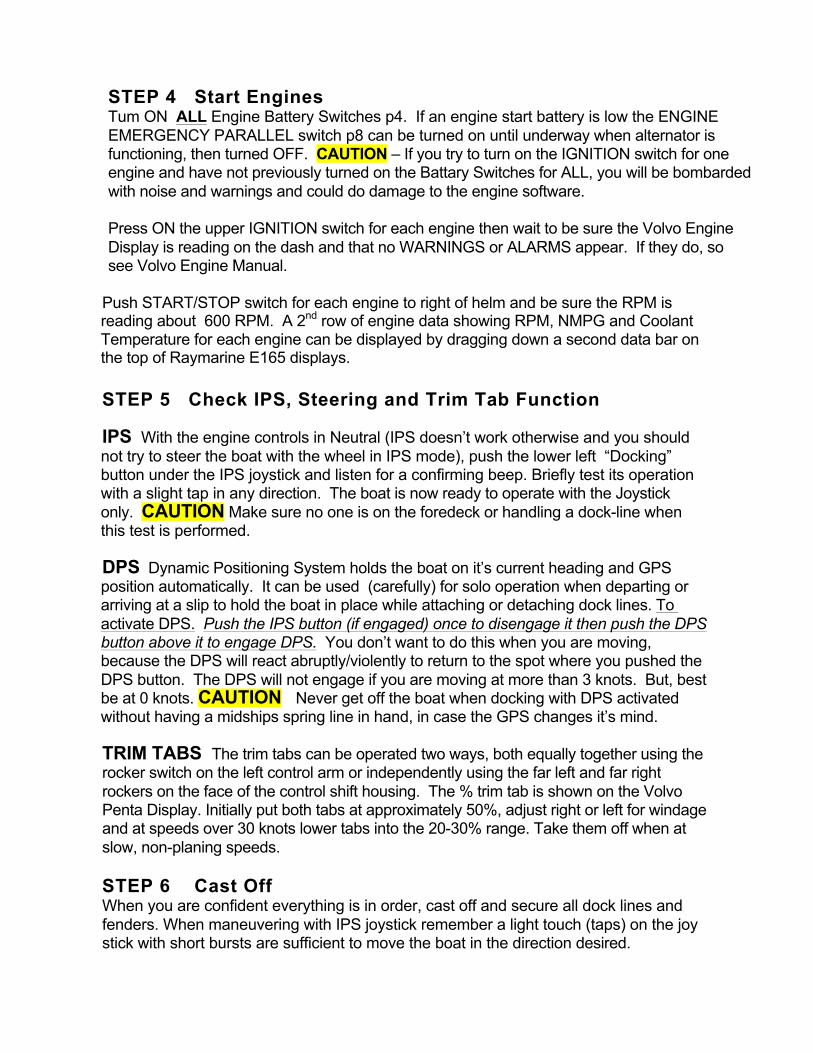
STEP 4 Start Engines
Tum ON ALL Engine Battery Switches p4. If an engine start battery is low the ENGINE EMERGENCY PARALLEL switch p8 can be turned on until underway when alternator is functioning, then turned OFF. CAUTION – If you try to turn on the IGNITION switch for one engine and have not previously turned on the Battary Switches for ALL, you will be bombarded with noise and warnings and could do damage to the engine software. Press ON the upper IGNITION switch for each engine then wait to be sure the Volvo Engine Display is reading on the dash and that no WARNINGS or ALARMS appear. If they do, so see Volvo Engine Manual.
Push START/STOP switch for each engine to right of helm and be sure the RPM is reading about 600 RPM. A 2nd row of engine data showing RPM, NMPG and Coolant Temperature for each engine can be displayed by dragging down a second data bar on the top of Raymarine E165 displays. STEP 5 Check IPS, Steering and Trim Tab Function IPS With the engine controls in Neutral (IPS doesn’t work otherwise and you should not try to steer the boat with the wheel in IPS mode), push the lower left “Docking” button under the IPS joystick and listen for a confirming beep. Briefly test its operation with a slight tap in any direction. The boat is now ready to operate with the Joystick only. CAUTION Make sure no one is on the foredeck or handling a dock-line when this test is performed. DPS Dynamic Positioning System holds the boat on it’s current heading and GPS position automatically. It can be used (carefully) for solo operation when departing or arriving at a slip to hold the boat in place while attaching or detaching dock lines. To activate DPS. Push the IPS button (if engaged) once to disengage it then push the DPS button above it to engage DPS. You don’t want to do this when you are moving, because the DPS will react abruptly/violently to return to the spot where you pushed the DPS button. The DPS will not engage if you are moving at more than 3 knots. But, best be at 0 knots. CAUTION Never get off the boat when docking with DPS activated without having a midships spring line in hand, in case the GPS changes it’s mind. TRIM TABS The trim tabs can be operated two ways, both equally together using the rocker switch on the left control arm or independently using the far left and far right rockers on the face of the control shift housing. The % trim tab is shown on the Volvo Penta Display. Initially put both tabs at approximately 50%, adjust right or left for windage and at speeds over 30 knots lower tabs into the 20-30% range. Take them off when at slow, non-planing speeds.
STEP 6 Cast Off When you are confident everything is in order, cast off and secure all dock lines and fenders. When maneuvering with IPS joystick remember a light touch (taps) on the joy stick with short bursts are sufficient to move the boat in the direction desired.
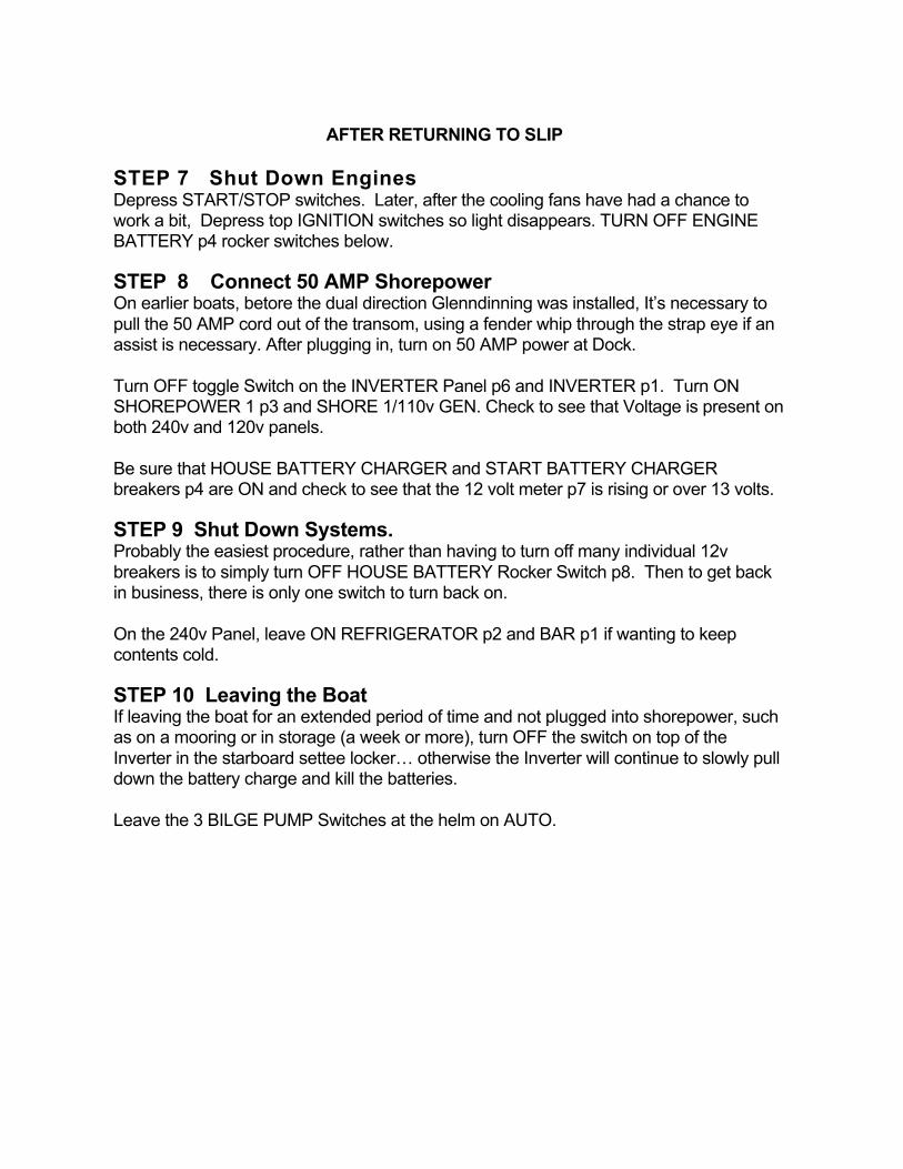
AFTER RETURNING TO SLIP STEP 7 Shut Down Engines Depress START/STOP switches. Later, after the cooling fans have had a chance to work a bit, Depress top IGNITION switches so light disappears. TURN OFF ENGINE BATTERY p4 rocker switches below. STEP 8 Connect 50 AMP Shorepower On earlier boats, betore the dual direction Glenndinning was installed, It’s necessary to pull the 50 AMP cord out of the transom, using a fender whip through the strap eye if an assist is necessary. After plugging in, turn on 50 AMP power at Dock. Turn OFF toggle Switch on the INVERTER Panel p6 and INVERTER p1. Turn ON SHOREPOWER 1 p3 and SHORE 1/110v GEN. Check to see that Voltage is present on both 240v and 120v panels.
Be sure that HOUSE BATTERY CHARGER and START BATTERY CHARGER breakers p4 are ON and check to see that the 12 volt meter p7 is rising or over 13 volts. STEP 9 Shut Down Systems. Probably the easiest procedure, rather than having to turn off many individual 12v breakers is to simply turn OFF HOUSE BATTERY Rocker Switch p8. Then to get back in business, there is only one switch to turn back on. On the 240v Panel, leave ON REFRIGERATOR p2 and BAR p1 if wanting to keep contents cold. STEP 10 Leaving the Boat If leaving the boat for an extended period of time and not plugged into shorepower, such as on a mooring or in storage (a week or more), turn OFF the switch on top of the Inverter in the starboard settee locker… otherwise the Inverter will continue to slowly pull down the battery charge and kill the batteries. Leave the 3 BILGE PUMP Switches at the helm on AUTO.
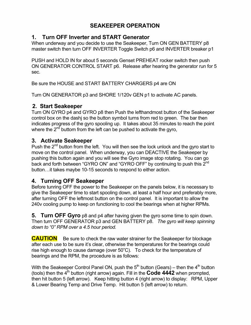
SEAKEEPER OPERATION
1. Turn OFF Inverter and START Generator When underway and you decide to use the Seakeeper, Turn ON GEN BATTERY p8 master switch then turn OFF INVERTER Toggle Switch p6 and INVERTER breaker p1 PUSH and HOLD IN for about 5 seconds Genset PREHEAT rocker switch then push ON GENERATOR CONTROL START p6. Release after hearing the generator run for 5 sec. Be sure the HOUSE and START BATTERY CHARGERS p4 are ON Turn ON GENERATOR p3 and SHORE 1/120v GEN p1 to activate AC panels.
2. Start Seakeeper Turn ON GYRO p4 and GYRO p8 then Push the lefthandmost button of the Seakeeper control box on the dashj so the button symbol turns from red to green. The bar then indicates progress of the gyro spooling up. It takes about 35 minutes to reach the point where the 2nd buttom from the left can be pushed to activate the gyro, 3. Activate Seakeeper Push the 2nd button from the left. You will then see the lock unlock and the gyro start to move on the control panel. When underway, you can DEACTIVE the Seakeeper by pushing this button again and you will see the Gyro image stop rotating. You can go back and forth between “GYRO ON” and “GYRO OFF” by continuing to push this 2nd button…it takes maybe 10-15 seconds to respond to either action. 4. Turning OFF Seakeeper Before tunring OFF the power to the Seakeeper on the panels below, it is necessary to give the Seakeeper time to start spooling down, at least a half hour and preferably more, after turning OFF the leftmost button on the control panel. It is important to allow the 240v cooling pump to keep on functioning to cool the bearings when at higher RPMs. 5. Turn OFF Gyro p8 and p4 after having given the gyro some time to spin down. Then turn OFF GENERATOR p3 and GEN BATTERY p8. The gyro will keep spinning down to “0” RPM over a 4.5 hour period.
CAUTION Be sure to check the raw water strainer for the Seakeeper for blockage after each use to be sure it’s clear, otherwise the temperatures for the bearings could rise high enough to cause damage (over 50”C). To check for the temperature of bearings and the RPM, the procedure is as follows: With the Seakeeper Control Panel ON, push the 5th button (Gears) – then the 4th button (tools) then the 4th button (right arrow) again. Fill in the Code 4442 when prompted, then hit button 5 (left arrow). Keep hitting button 4 (right arrow) to display: RPM, Upper & Lower Bearing Temp and Drive Temp. Hit button 5 (left arrow) to return.