MITSUBISHI CNC M70V Seriesdl.mitsubishielectric.com/.../cnc/.../bnpa1218engf.pdfMITSUBISHI CNC PLC...
13
series M70 V series M70 V MITSUBISHI CNC M70V Series
Transcript of MITSUBISHI CNC M70V Seriesdl.mitsubishielectric.com/.../cnc/.../bnpa1218engf.pdfMITSUBISHI CNC PLC...
seriesM70VseriesM70V
MITSUBISHI CNCM70V Series
CN
C M
70VS
erie
s (EN
GLIS
H)
BN
P-A1218-F[EN
G]
K-KL2-0-C0063-F NA1312 Printed in Japan (MDOC)
Revised publication, effective Dec. 2013.Superseding publication of K-KL2-0-C0063-E Aug. 2013.
Specifications are subject to change without notice.
BNP-A1218-F[ENG](ENGLISH)
1 2
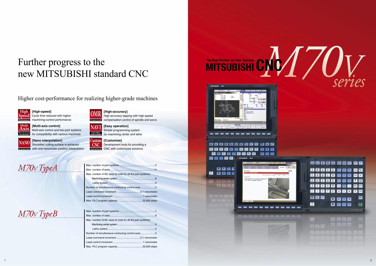
Further progress to thenew MITSUBISHI standard CNC
Higher cost-performance for realizing higher-grade machines
[High-accuracy] High-accuracy tapping with high-speed compensation control of spindle and servo
[Easy operation]Simple programming system for machining center and lathe
[Customize]Development tools for providing a CNC with customized solutions
[Nano interpolation]Smoother cutting surface is achieved with one-nanometer position interpolation
[High-speed] Cycle time reduced with higher machining-control performance
HighSpeedPerformance
[Multi-axis control]Multi-axis control and two-part systems for compatibility with various machines
MultiAxis
Max. number of part systems ...................................................2
Max. number of axes.............................................................. 11
Max. number of NC axes (in total for all the part systems)
Machining center system .....................................................8
Lathe system ...................................................................9
Number of simultaneous contouring control axes ....................4
Least command increment ..................................0.1 micrometer
Least control increment .......................................... 1 nanometer
Max. PLC program capacity................................... 32,000 steps
Max. number of part systems ...................................................1
Max. number of axes................................................................9
Max. number of NC axes (in total for all the part systems)
Machining center system .....................................................5
Lathe system ...................................................................5
Number of simultaneous contouring control axes ....................5
Least command increment ..................................0.1 micrometer
Least control increment .......................................... 1 nanometer
Max. PLC program capacity................................... 20,000 steps
The Best Partner for Your Success
MITSUBISHI CNC
M70V TypeA
M70V TypeB
3 4
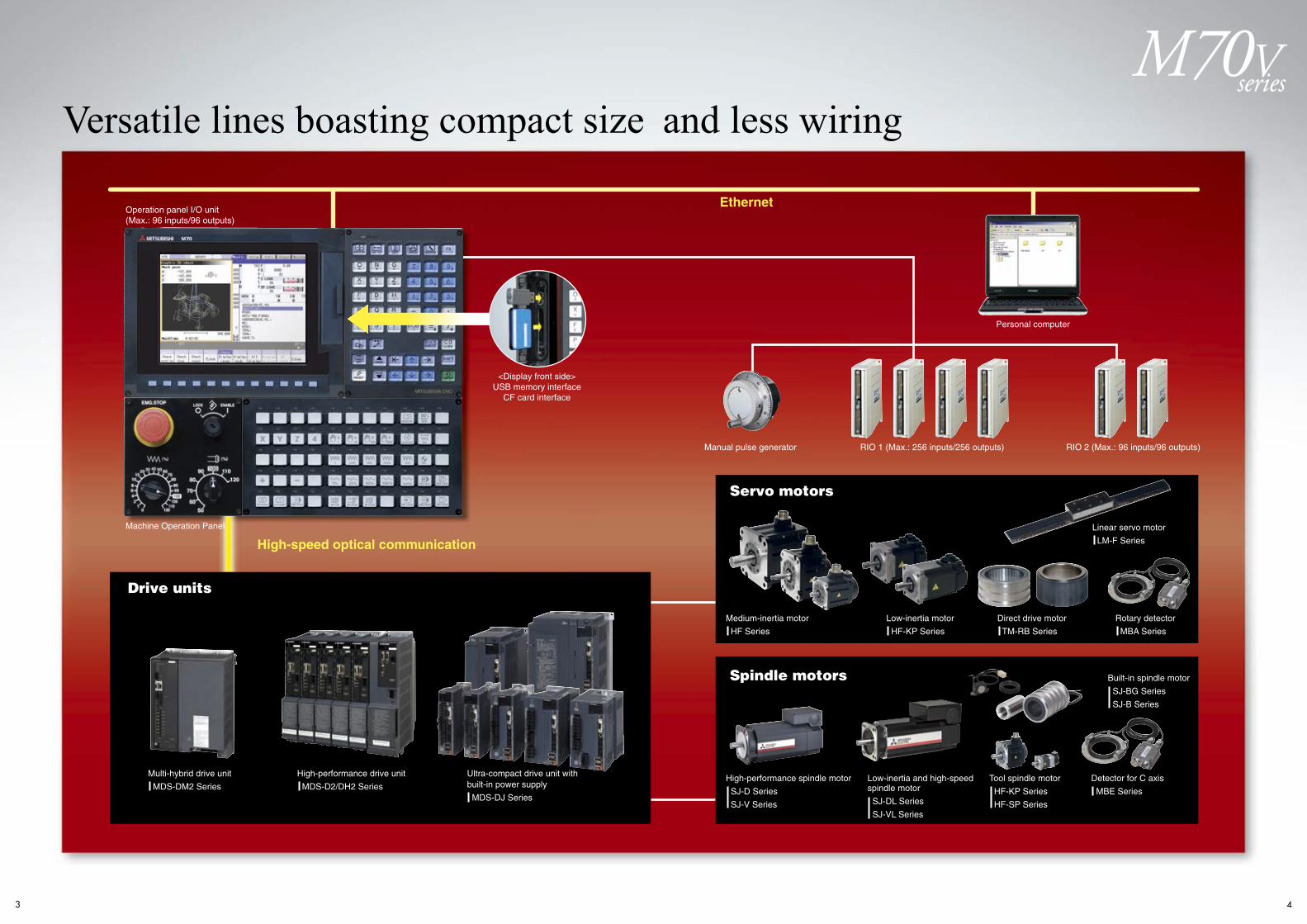
Versatile lines boasting compact size and less wiring
Ethernet
Machine Operation Panel
Manual pulse generator
Personal computer
RIO 1 (Max.: 256 inputs/256 outputs) RIO 2 (Max.: 96 inputs/96 outputs)
High-speed optical communication
seriesM70VseriesM70V
Low-inertia and high-speed spindle motor
SJ-DL Series
SJ-VL Series
Tool spindle motor
HF-KP Series
HF-SP Series
Low-inertia motor
HF-KP Series
Direct drive motor
TM-RB Series
Linear servo motor
LM-F Series
Drive units
Servo motors
Spindle motors
High-performance drive unit
MDS-D2/DH2 Series
Multi-hybrid drive unit
MDS-DM2 Series
Ultra-compact drive unit with built-in power supply
MDS-DJ Series
Operation panel I/O unit (Max.: 96 inputs/96 outputs)
<Display front side>USB memory interface
CF card interface
Medium-inertia motor
HF Series
High-performance spindle motor
SJ-D Series
SJ-V Series
Built-in spindle motor
SJ-BG Series
SJ-B Series
Rotary detector
MBA Series
Detector for C axis
MBE Series
5 6
Deceleration is performed with the maximum torque to minimize
the spindle orientation time.
The spindle's constant position loop control has eliminated the
zero point return time when switching from the spindle to C-axis.
High traceability to command (High-gain control II), which has
been developed in servo axis control, is now available for the
spindles, contributing to shorter machining time and higher
accuracy.
A high-speed error-compensation function is used for controlling
the spindle and servo, enabling accurate tapping.
Spindle drive unit
Directly compensatessynchronization error
Spindle motorServo motor
Servo drive unit
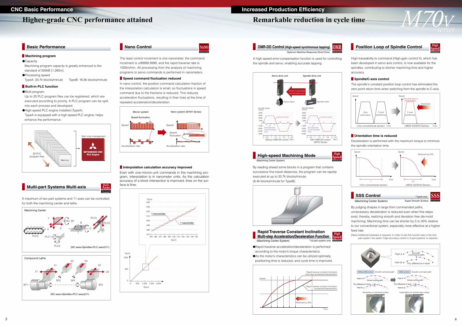
The least control increment is one nanometer, the command
increment is ±99999.9999, and the rapid traverse rate is
1000m/min. All processing from the analysis of machining
programs to servo commands is performed in nanometers.
In nano control, the position command calculation fraction of
the interpolation calculation is small, so fluctuations in speed
command due to the fractions is reduced. This reduces
acceleration fluctuations, resulting in finer lines at the time of
repeated acceleration/deceleration.
Even with one-micron-unit commands in the machining pro-gram, interpolation is in nanometer units. As the calculation accuracy of a block intersection is improved, lines on the sur-face is finer.
A maximum of two part systems and 11 axes can be controlled
for both the machining center and lathe.
Nano system (M70V Series)Micron system
SpeedSpeed
Acceleration rateAcceleration rate
Speed fluctuation
Speed fluctuation
SP1
(NC axes+Spindles+PLC axes≦11)
SP2
SP3 SP4
Z1 Z2
X1 X2
X3 X4
By reading ahead some blocks in a program that contains
successive fine travel distances, the program can be rapidly
executed at up to 33.7k blocks/minute.
(8.4k blocks/minute for TypeB)
Basic Performance Nano Control OMR-DD Control (High-speed synchronous tapping) Position Loop of Spindle Control
High-speed Machining Mode
�Rapid traverse acceleration/deceleration is performed
according to the motor’s torque characteristics.
�As the motor’s characteristics can be utilized optimally,
positioning time is reduced, and cycle time is improved.
Rapid Traverse Constant InclinationMulti-step Acceleration/Deceleration Function
Multi-part Systems Multi-axis
Speed command fluctuation reduced Spindle/C-axis control
Orientation time is reduced
Interpolation calculation accuracy improved
�Capacity
Machining program capacity is greatly enhanced to the
standard of 500kB [1,280m].
�Processing speed
TypeA: 33.7k blocks/minute TypeB: 16.8k blocks/minute
Machining program
�Multi-program
Up to 20 PLC program files can be registered, which are
executed according to priority. A PLC program can be split
into each process and developed.
�High-speed PLC engine installed (TypeA)
TypeA is equipped with a high-speed PLC engine, helps
enhance the performance.
Built-in PLC function
seriesM70VOptimum Machine Response Direct Drive
20 PLCprogram files
Start order management
Memory
MITSUBISHI CNCPLC Engine
Remarkable reduction in cycle timeHigher-grade CNC performance attainedCNC Basic Performance Increased Production Efficiency
seriesM70V
HighSpeedPerformance
HighSpeedPerformance
HighSpeedPerformance
PLC3 PLC1
B
PLC4SP
PLC5
(NC axes+Spindles+PLC axes≦11)
C
PLC2
X Z
Y
MultiAxis
1,000
500
00 500 1,000 1,500 2,000
Y(µm)
X(µm)
1,050
540
530
520
510
500
490
480
470
Y(µm)
X(µm)
1-micrometer
1-nanometer
950 960 970 980 990 1,000 1,010 1,020 1,030 1,040
Machining Center
Compound Lathe
(Machining Center System)
(Machining Center System) *1st part system only
Time Time
C-axispositioning
Zeropoint return
C-axispositioning
SpeedSpeed
Shortened
Zero point return isnot necessary.
<Our conventional series> <MDS-D2/DH2 Series>
Time
Speed Speed
Time
Reduced by 20%
1 0.8
<Our conventional series> <MDS-D2/DH2 Series>
−4000
−3000
0 0.5 1 1.5 2 2.5 3 3.5Without OMR-DD control
Servo/spindlesynchronization error
Spindle speed
Servo/spindlesynchronization error
Spindle speed
With OMR-DD control (M70V Series)
−2000
−1000
1000
20003000
4000
0
−4000
−3000
0 0.5 1 1.5 2 2.5 3 3.5
−2000
−1000
1000
20003000
4000
0
(Sec.) (Sec.)
Spindle speed(r/min)
Spindle speed(r/min)
Speed
Time
Rapid traverse constant inclinationacceleration/deceleration
Rapid traverse constant inclinationmulti-step acceleration/deceleration
Reduced by 30%
(Note) Additional hardware is required. In order to use this function also in the 2nd part system, the option "High-accuracy control in 2 part systems" is required.
* TypeA onlySSS ControlSuper Smooth Surface
By judging shapes in large from commanded paths,
unnecessary deceleration is reduced even when fine steps
exist; thereby, realizing smooth and deviation free die-mold
machining. Machining time can be shorter by 5 to 30% relative
to our conventional system, especially more effective at a higher
feed rate.
Path A
Path B
Smooth command path
Tiny difference in level
Without SSS control
Scratches on machined surface Interpolation for smooth step cutting
SSS control Smooth command path
With SSS controlWithout SSS control
Smooth command path
Actual cutting pathPath A
Path B
Tiny difference in level
Actual cutting pathPath A
Path B
Tiny difference in level
(Machining Center System)
7 8
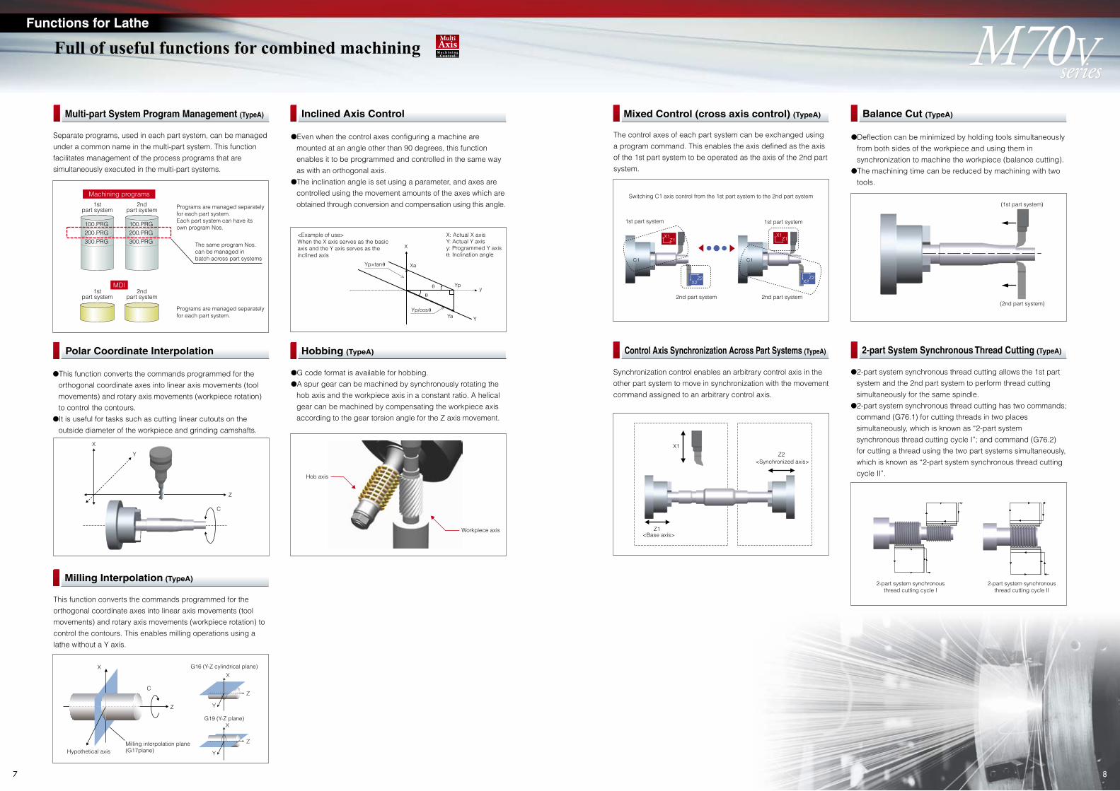
Full of useful functions for combined machiningFunctions for Lathe
MultiAxis
Synchronization control enables an arbitrary control axis in the
other part system to move in synchronization with the movement
command assigned to an arbitrary control axis.
X1Z2
<Synchronized axis>
Z1 <Base axis>
Control Axis Synchronization Across Part Systems (TypeA)
�This function converts the commands programmed for the
orthogonal coordinate axes into linear axis movements (tool
movements) and rotary axis movements (workpiece rotation)
to control the contours.
�It is useful for tasks such as cutting linear cutouts on the
outside diameter of the workpiece and grinding camshafts.
Polar Coordinate Interpolation
This function converts the commands programmed for the
orthogonal coordinate axes into linear axis movements (tool
movements) and rotary axis movements (workpiece rotation) to
control the contours. This enables milling operations using a
lathe without a Y axis.
Y
X
Z
C
Milling Interpolation (TypeA)
�2-part system synchronous thread cutting allows the 1st part
system and the 2nd part system to perform thread cutting
simultaneously for the same spindle.
�2-part system synchronous thread cutting has two commands;
command (G76.1) for cutting threads in two places
simultaneously, which is known as “2-part system
synchronous thread cutting cycle I”; and command (G76.2)
for cutting a thread using the two part systems simultaneously,
which is known as “2-part system synchronous thread cutting
cycle II”.
2-part system synchronousthread cutting cycle I
2-part system synchronousthread cutting cycle II
2-part System Synchronous Thread Cutting (TypeA)
�Deflection can be minimized by holding tools simultaneously
from both sides of the workpiece and using them in
synchronization to machine the workpiece (balance cutting).
�The machining time can be reduced by machining with two
tools.
(1st part system)
(2nd part system)
Balance Cut (TypeA)
�Even when the control axes configuring a machine are
mounted at an angle other than 90 degrees, this function
enables it to be programmed and controlled in the same way
as with an orthogonal axis.
�The inclination angle is set using a parameter, and axes are
controlled using the movement amounts of the axes which are
obtained through conversion and compensation using this angle.
<Example of use>When the X axis serves as the basicaxis and the Y axis serves as theinclined axis
X: Actual X axisY: Actual Y axisy: Programmed Y axisθ: Inclination angle
Yp/cosθ
Yp×tanθ
X
Y
y
Xa
Yp
Ya
θ
θ
Inclined Axis Control
�G code format is available for hobbing.
�A spur gear can be machined by synchronously rotating the
hob axis and the workpiece axis in a constant ratio. A helical
gear can be machined by compensating the workpiece axis
according to the gear torsion angle for the Z axis movement.
Hob axis
Workpiece axis
Hobbing (TypeA)
The control axes of each part system can be exchanged using
a program command. This enables the axis defined as the axis
of the 1st part system to be operated as the axis of the 2nd part
system.
X1Z1
X2Z2
C1
1st part system
2nd part system
Switching C1 axis control from the 1st part system to the 2nd part system
1st part system
C1
X1Z1
X2Z2
2nd part system
Mixed Control (cross axis control) (TypeA)
Separate programs, used in each part system, can be managed
under a common name in the multi-part system. This function
facilitates management of the process programs that are
simultaneously executed in the multi-part systems.
Multi-part System Program Management (TypeA)
100.PRG 200.PRG 300.PRG
1stpart system
100.PRG 200.PRG 300.PRG
2ndpart system Programs are managed separately
for each part system.Each part system can have itsown program Nos.
Programs are managed separately for each part system.
1stpart system
2ndpart system
The same program Nos. can be managed in batch across part systems
Machining programs
MDI
seriesM70VseriesM70V
Hypothetical axisMilling interpolation plane(G17plane)
X
C
Z
G16 (Y-Z cylindrical plane)
G19 (Y-Z plane)
9 10
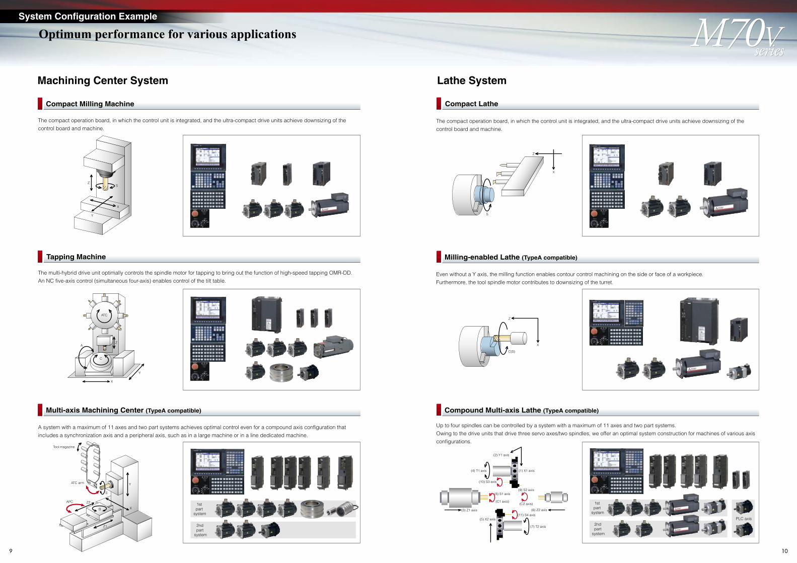
seriesM70VOptimum performance for various applicationsSystem Configuration Example
seriesM70VMachining Center System
The multi-hybrid drive unit optimally controls the spindle motor for tapping to bring out the function of high-speed tapping OMR-DD.
An NC five-axis control (simultaneous four-axis) enables control of the tilt table.
A system with a maximum of 11 axes and two part systems achieves optimal control even for a compound axis configuration that
includes a synchronization axis and a peripheral axis, such as in a large machine or in a line dedicated machine.
The compact operation board, in which the control unit is integrated, and the ultra-compact drive units achieve downsizing of the
control board and machine.
Tapping Machine
Multi-axis Machining Center (TypeA compatible)
Compact Milling Machine
Lathe System
Even without a Y axis, the milling function enables contour control machining on the side or face of a workpiece.
Furthermore, the tool spindle motor contributes to downsizing of the turret.
The compact operation board, in which the control unit is integrated, and the ultra-compact drive units achieve downsizing of the
control board and machine.
Up to four spindles can be controlled by a system with a maximum of 11 axes and two part systems.
Owing to the drive units that drive three servo axes/two spindles, we offer an optimal system construction for machines of various axis
configurations.
Compact Lathe
Compound Multi-axis Lathe (TypeA compatible)
Milling-enabled Lathe (TypeA compatible)
(2) Y1 axis
(1) X1 axis
(5) X2 axis(11) S4 axis
(4) T1 axis
(7) T2 axis
(10) S3 axis
(8) S1 axis
(3) Z1 axis (6) Z2 axis
(C1 axis)(C2 axis)
(9) S2 axis
PLC axis
X
Y
ZS
ZA
ATC
X
Y
C
S
X
Z
C(S)
X
Z
ATC arm
Tool magazine
Y
X
Z1
APC Z2
B
S
1st part
system
2nd part
system
1st part
system
2nd part
system
11 12
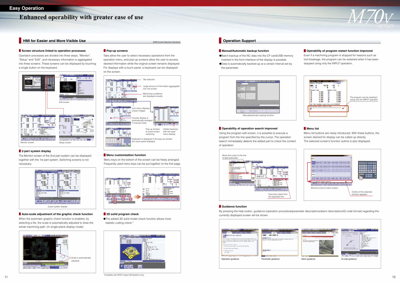
seriesM70VEnhanced operability with greater ease of useEasy Operation
seriesM70V
Tabs allow the user to select necessary operations from the
operation menu, and pop-up screens allow the user to access
desired information while the original screen remains displayed.
For displays with a touch panel, a keyboard can be displayed
on the screen.
Operation processes are divided into three steps, “Monitor”,
“Setup” and “Edit”, and necessary information is aggregated
into three screens. These screens can be displayed by touching
a single button on the keyboard.
Menu keys on the bottom of the screen can be freely arranged.
Frequently used menu keys can be put together on the first page.
Edit screen
Setup screenMonitor screen
Tab selection
Large amount of information aggregatedinto one screen
Machining conditions are displayed visually
Icon menu displaysscreen images
Counter display is automatically enlarged in manual mode
Pop-up windowto avoid screenswitching
Keyboard is displayed in the pop-up window (for touch-panel displays)
Visible hierarchy with two-layer menu display
The Monitor screen of the 2nd part system can be displayed
together with the 1st part system. Switching screens is not
necessary.
2-part system display
HMI for Easier and More Visible Use
Screen structure linked to operation processes Pop-up screens
2-part system display
When the automatic graphic check function is enabled, by
selecting a file, the scale is automatically adjusted to draw the
whole machining path. (In single-plane display mode)
Scale is automatically
adjusted
Auto-scale adjustment of the graphic check function
Menu customization function
�The added 3D solid model check function allows more
realistic cutting check.*
3D solid program check
�Batch-backup of the NC data into the CF card/USB memory
inserted in the front interface of the display is possible.
�Data is automatically backed-up at a certain interval set by
the parameter.
Manual/automatic backup function
Using the program edit screen, it is possible to execute a
program from the line specified by the cursor. The operation
search immediately detects the edited part to check the content
of operation.
By pressing the help button, guidance (operation procedure/parameter descriptions/alarm descriptions/G code format) regarding the
currently displayed screen will be shown.
Move the cursor to the line to start execution
INPUT
Operation guidance Parameter guidance Alarm guidance G-code guidance
Operation Support
Manual/Automatic backup function
Operability of operation search improved
Guidance function
The program can be restarted using only the INPUT operation
Even if a machining program is stopped for reasons such as
tool breakage, the program can be restarted when it has been
stopped using only the INPUT operation.
Operability of program restart function improved
Menu list buttons are newly introduced. With these buttons, the
screen desired for display can be called up directly.
The selected screen’s function outline is also displayed.
Menu list
Execution starts from the specified line
(HMI:Human Machine Interface)
Shortcut icons to each screen
Outline of the selected function appears
*Available with M70V TypeA (M System) only.
13 14
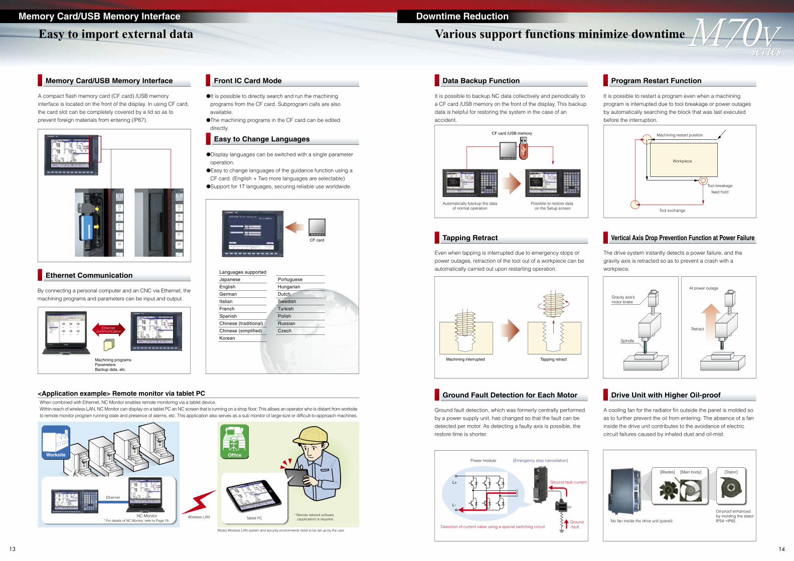
seriesM70VEasy to import external dataMemory Card/USB Memory Interface
Various support functions minimize downtimeDowntime Reduction
seriesM70V
A compact flash memory card (CF card) /USB memory
interface is located on the front of the display. In using CF card,
the card slot can be completely covered by a lid so as to
prevent foreign materials from entering (IP67).
�It is possible to directly search and run the machining
programs from the CF card. Subprogram calls are also
available.
�The machining programs in the CF card can be edited
directly.
�Display languages can be switched with a single parameter
operation.
�Easy to change languages of the guidance function using a
CF card. (English + Two more languages are selectable)
�Support for 17 languages, securing reliable use worldwide.
Memory Card/USB Memory Interface Front IC Card Mode
By connecting a personal computer and an CNC via Ethernet, the
machining programs and parameters can be input and output.
Ethernet Communication
Easy to Change Languages
It is possible to restart a program even when a machining
program is interrupted due to tool breakage or power outages
by automatically searching the block that was last executed
before the interruption.
It is possible to backup NC data collectively and periodically to
a CF card /USB memory on the front of the display. This backup
data is helpful for restoring the system in the case of an
accident.
Machining restart position
Workpiece
Tool exchange
Tool breakage
feed hold
The drive system instantly detects a power failure, and the
gravity axis is retracted so as to prevent a crash with a
workpiece.
Even when tapping is interrupted due to emergency stops or
power outages, retraction of the tool out of a workpiece can be
automatically carried out upon restarting operation.
Ground fault detection, which was formerly centrally performed
by a power supply unit, has changed so that the fault can be
detected per motor. As detecting a faulty axis is possible, the
restore time is shorter.
A cooling fan for the radiator fin outside the panel is molded so
as to further prevent the oil from entering. The absence of a fan
inside the drive unit contributes to the avoidance of electric
circuit failures caused by inhaled dust and oil-mist.
Machining interrupted Tapping retract
CF card /USB memory
Automatically backup the dataof normal operation
Possible to restore data on the Setup screen
Detection of current value using a special switching circuitGround-fault
Ground-fault current
[Emergency stop cancellation]Power module
No fan inside the drive unit (panel)
[Stator]
Oil-proof enhanced by molding the stator IP54�IP65
[Blades] [Main body]
Data Backup Function Program Restart Function
Tapping Retract Vertical Axis Drop Prevention Function at Power Failure
Ground Fault Detection for Each Motor Drive Unit with Higher Oil-proof
Ethernet communication
Machining programsParametersBackup data, etc.
Languages supported
Japanese
English
German
Italian
French
Spanish
Chinese (traditional)
Chinese (simplified)
Korean
CF card
Portuguese
Hungarian
Dutch
Swedish
Turkish
Polish
Russian
Czech
Spindle
Gravity axis’smotor brake
At power outage
Retract
L+
L-
NC Monitor
Ethernet
* For details of NC Monitor, refer to Page 18.
* Remote network software (application) is required.
(Note) Wireless LAN system and security environments need to be set up by the user.
Wireless LAN
OfficeOfficeWorksiteWorksite
Tablet PC
<Application example> Remote monitor via tablet PCWhen combined with Ethernet, NC Monitor enables remote monitoring via a tablet device.Within reach of wireless LAN, NC Monitor can display on a tablet PC an NC screen that is running on a shop floor. This allows an operator who is distant from worksite to remote monitor program running state and presence of alarms, etc. This application also serves as a sub monitor of large-size or difficult-to-approach machines.
15 16
seriesM70VCreate machining programs on a personal computer
Simple programming tools,"NAVI MILL" and "NAVI LATHE"
Simple Programming Functions User Support Tools
seriesM70V
Intuitively view system configuration and machining programs
Machining programs using macro programs enable commands to be added between processes via the editing screen. Machine tool builders can customize the macro program of each process according to machine specifications and machining know-how.
Detects input errors for troubleshooting.
Interface Design with Overall View
Automatic Setting of Cutting Conditions
Checker and Guidance Functions
Customize Machining Programs
Menu
Displays the tool path or machining shape of a program in graphic form.NAVI MILL
Message guidance
Checker
NAVI LATHE
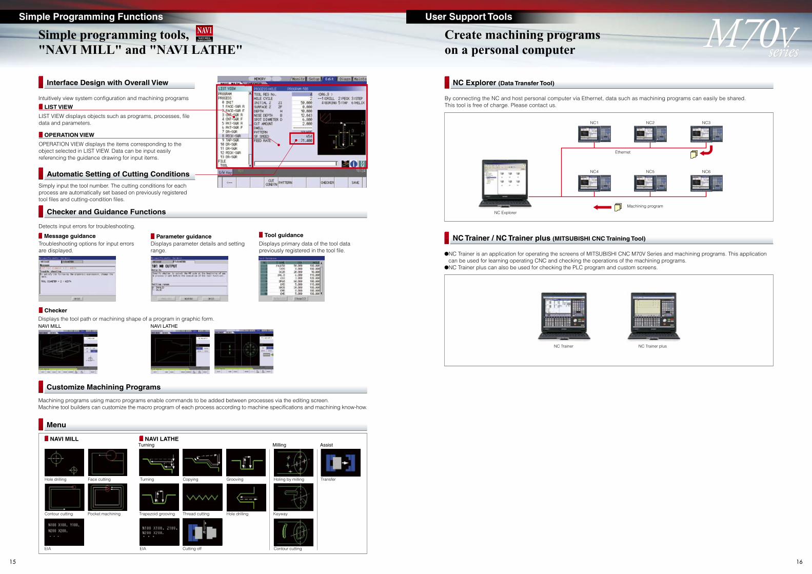
By connecting the NC and host personal computer via Ethernet, data such as machining programs can easily be shared. This tool is free of charge. Please contact us.
NC1 NC2 NC3
NC4
Machining program
Ethernet
NC Explorer
NC5 NC6
NC Explorer (Data Transfer Tool)
�NC Trainer is an application for operating the screens of MITSUBISHI CNC M70V Series and machining programs. This application can be used for learning operating CNC and checking the operations of the machining programs.
�NC Trainer plus can also be used for checking the PLC program and custom screens.
NC Trainer / NC Trainer plus (MITSUBISHI CNC Training Tool)
LIST VIEW displays objects such as programs, processes, file data and parameters.
Troubleshooting options for input errors are displayed.
Parameter guidanceDisplays parameter details and setting range.
Tool guidance
Displays primary data of the tool data previously registered in the tool file.
LIST VIEW
OPERATION VIEW displays the items corresponding to the object selected in LIST VIEW. Data can be input easily referencing the guidance drawing for input items.
Simply input the tool number. The cutting conditions for each process are automatically set based on previously registered tool files and cutting-condition files.
OPERATION VIEW
NAVI MILL NAVI LATHE
Hole drilling Face cutting
Contour cutting Pocket machining
EIA
Turning Milling Assist
Thread cutting Hole drilling
EIA Contour cutting
Transfer
Cutting off
Turning Copying Grooving
Trapezoid grooving
Holing by milling
Keyway
NC Trainer NC Trainer plus�
17 18
seriesM70V<Custom screen development>Make your CNC more user-friendly by developing original screens
<Sequence program development> Editable on both personal computers and HMI screens
Development Tools
<Easy setup>Offering a wide range of support tools, from machine design to setup
seriesM70VMore comfortable development environment
Develop screen configuration
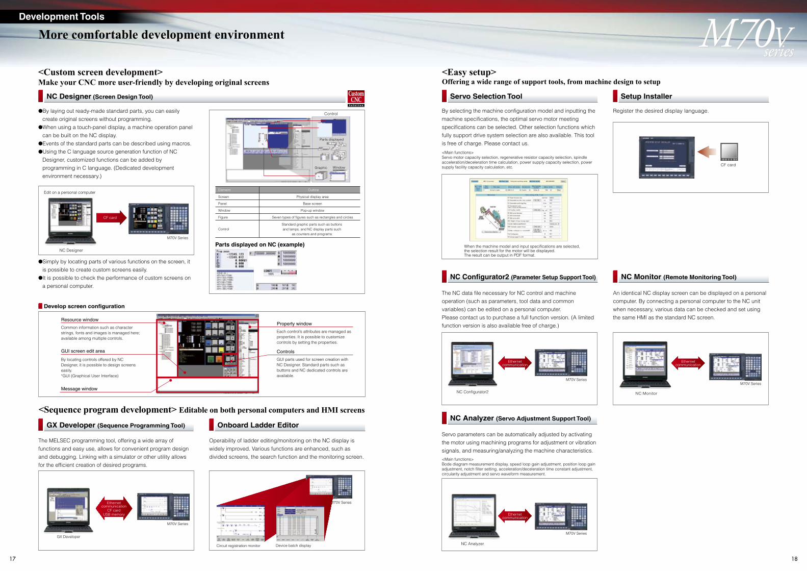
NC Designer (Screen Design Tool)
Onboard Ladder EditorGX Developer (Sequence Programming Tool)
�By laying out ready-made standard parts, you can easily
create original screens without programming.
�When using a touch-panel display, a machine operation panel
can be built on the NC display.
�Events of the standard parts can be described using macros.
�Using the C language source generation function of NC
Designer, customized functions can be added by
programming in C language. (Dedicated development
environment necessary.)
�Simply by locating parts of various functions on the screen, it
is possible to create custom screens easily.
�It is possible to check the performance of custom screens on
a personal computer.
Element Outline
Control
Screen
Panel
Window
Figure
Physical display area
Base screen
Pop-up window
Seven types of figures such as rectangles and circles
Standard graphic parts such as buttonsand lamps, and NC display parts such
as counters and programs
Parts displayed on NC (example)
Resource window
GUI screen edit area
Common information such as character strings, fonts and images is managed here; available among multiple controls.
By locating controls offered by NC Designer, it is possible to design screens easily.*GUI (Graphical User Interface)
Property window
Each control’s attributes are managed as properties. It is possible to customize controls by setting the properties.
Controls
GUI parts used for screen creation with NC Designer. Standard parts such as buttons and NC dedicated controls are available.
Message window
M70V Series
M70V Series
M70V Series
M70V Series
Edit on a personal computer
NC Designer
The MELSEC programming tool, offering a wide array of
functions and easy use, allows for convenient program design
and debugging. Linking with a simulator or other utility allows
for the efficient creation of desired programs.
Operability of ladder editing/monitoring on the NC display is
widely improved. Various functions are enhanced, such as
divided screens, the search function and the monitoring screen.
GX Developer
M70V Series
Circuit registration monitor Device batch display
Servo Selection Tool
NC Configurator2 (Parameter Setup Support Tool)
NC Analyzer (Servo Adjustment Support Tool)
Setup Installer
Register the desired display language.
Servo parameters can be automatically adjusted by activating
the motor using machining programs for adjustment or vibration
signals, and measuring/analyzing the machine characteristics.
<Main functions>Bode diagram measurement display, speed loop gain adjustment, position loop gain adjustment, notch filter setting, acceleration/deceleration time constant adjustment, circularity adjustment and servo waveform measurement.
The NC data file necessary for NC control and machine
operation (such as parameters, tool data and common
variables) can be edited on a personal computer.
Please contact us to purchase a full function version. (A limited
function version is also available free of charge.)
Ethernetcommunication
Ethernetcommunication
NC Analyzer
NC Configurator2
Ethernetcommunication
By selecting the machine configuration model and inputting the
machine specifications, the optimal servo motor meeting
specifications can be selected. Other selection functions which
fully support drive system selection are also available. This tool
is free of charge. Please contact us.
<Main functions>Servo motor capacity selection, regenerative resistor capacity selection, spindle acceleration/deceleration time calculation, power supply capacity selection, power supply facility capacity calculation, etc.
When the machine model and input specifications are selected, the selection result for the motor will be displayed. The result can be output in PDF format.
M70V Series
NC Monitor (Remote Monitoring Tool)
An identical NC display screen can be displayed on a personal
computer. By connecting a personal computer to the NC unit
when necessary, various data can be checked and set using
the same HMI as the standard NC screen.
CF card
Ethernetcommunication
CF cardUSB memory
Control
Parts displayed
WindowGraphic
NC Monitor
CF card
19 20
seriesM70VNetwork Functions / Extendibility
seriesM70V
The optical cable can be extended to a maximum of 90m by
connecting up to two optical servo communication repeater
units between the CNC unit and a servo drive unit.
The NC unit can be connected to a network to serve as the
master/local station of the MELSEC CC-Link.
CC-Link Optical Communication Repeater Unit
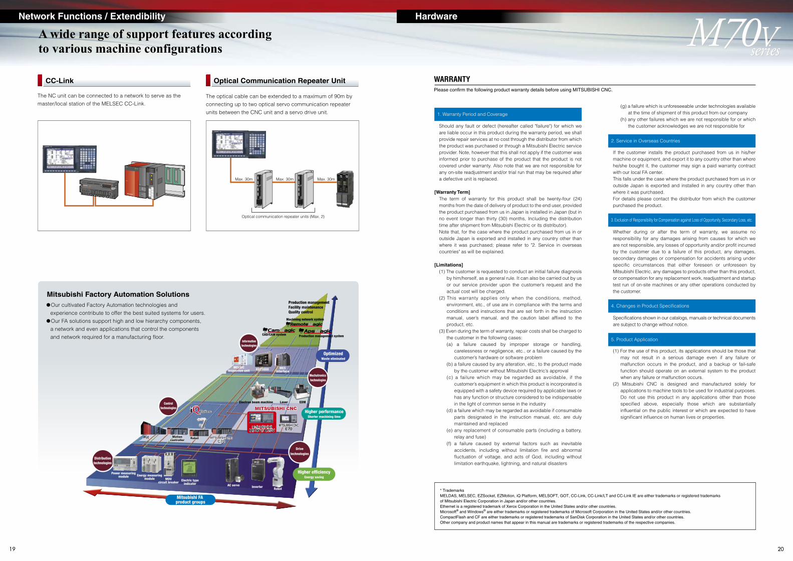
�Our cultivated Factory Automation technologies and
experience contribute to offer the best suited systems for users.�Our FA solutions support high and low hierarchy components,
a network and even applications that control the components
and network required for a manufacturing floor.
Max. 30m
Optical communication repeater units (Max. 2)
Max. 30m Max. 30m
Mitsubishi Factory Automation Solutions
A wide range of support features according to various machine configurations
Hardware
Production management Facility maintenance Quality control
Machining network system
CAD/CAM system
MELQICinspection unit
Electron beam machine
Motioncontroller
Motioncontroller
Power measuringmodule Energy measuring
module MDUcircuit breaker Electric type
indicator AC servo Inverter Robot
RobotRobotPLCPLC
Laser EDM
MESinterface
GOT1000
Informationtechnologies
Controltechnologies
Distributiontechnologies
Mechatronics technologies
Drivetechnologies
OptimizedWaste eliminated
Higher performanceShorter machining time
Production management system
Higher efficiencyEnergy saving
Mitsubishi FA product groups
MITSUBISHI CNCM700V/M70V
MITSUBISHI CNCE70
* TrademarksMELDAS, MELSEC, EZSocket, EZMotion, iQ Platform, MELSOFT, GOT, CC-Link, CC-Link/LT and CC-Link IE are either trademarks or registered trademarks of Mitsubishi Electric Corporation in Japan and/or other countries.Ethernet is a registered trademark of Xerox Corporation in the United States and/or other countries.Microsoft® and Windows® are either trademarks or registered trademarks of Microsoft Corporation in the United States and/or other countries.CompactFlash and CF are either trademarks or registered trademarks of SanDisk Corporation in the United States and/or other countries.Other company and product names that appear in this manual are trademarks or registered trademarks of the respective companies.
WARRANTYPlease confirm the following product warranty details before using MITSUBISHI CNC.
Should any fault or defect (hereafter called "failure") for which we are liable occur in this product during the warranty period, we shall provide repair services at no cost through the distributor from which the product was purchased or through a Mitsubishi Electric service provider. Note, however that this shall not apply if the customer was informed prior to purchase of the product that the product is not covered under warranty. Also note that we are not responsible for any on-site readjustment and/or trial run that may be required after a defective unit is replaced.
[Warranty Term]The term of warranty for this product shall be twenty-four (24) months from the date of delivery of product to the end user, provided the product purchased from us in Japan is installed in Japan (but in no event longer than thirty (30) months, Including the distribution time after shipment from Mitsubishi Electric or its distributor).Note that, for the case where the product purchased from us in or outside Japan is exported and installed in any country other than where it was purchased; please refer to "2. Service in overseas countries" as will be explained.
[Limitations](1) The customer is requested to conduct an initial failure diagnosis
by him/herself, as a general rule. It can also be carried out by us or our service provider upon the customer’s request and the actual cost will be charged.
(2) This warranty applies only when the conditions, method, environment, etc., of use are in compliance with the terms and conditions and instructions that are set forth in the instruction manual, user’s manual, and the caution label affixed to the product, etc.
(3) Even during the term of warranty, repair costs shall be charged to the customer in the following cases:(a) a failure caused by improper storage or handling,
carelessness or negligence, etc., or a failure caused by the customer’s hardware or software problem
(b) a failure caused by any alteration, etc., to the product made by the customer without Mitsubishi Electric’s approval
(c) a failure which may be regarded as avoidable, if the customer’s equipment in which this product is incorporated is equipped with a safety device required by applicable laws or has any function or structure considered to be indispensable in the light of common sense in the industry
(d) a failure which may be regarded as avoidable if consumable parts designated in the instruction manual, etc. are duly maintained and replaced
(e) any replacement of consumable parts (including a battery, relay and fuse)
(f) a failure caused by external factors such as inevitable accidents, including without limitation fire and abnormal fluctuation of voltage, and acts of God, including without limitation earthquake, lightning, and natural disasters
(g) a failure which is unforeseeable under technologies available at the time of shipment of this product from our company
(h) any other failures which we are not responsible for or which the customer acknowledges we are not responsible for
If the customer installs the product purchased from us in his/her machine or equipment, and export it to any country other than where he/she bought it, the customer may sign a paid warranty contract with our local FA center.This falls under the case where the product purchased from us in or outside Japan is exported and installed in any country other than where it was purchased.For details please contact the distributor from which the customer purchased the product.
Whether during or after the term of warranty, we assume no responsibility for any damages arising from causes for which we are not responsible, any losses of opportunity and/or profit incurred by the customer due to a failure of this product, any damages, secondary damages or compensation for accidents arising under specific circumstances that either foreseen or unforeseen by Mitsubishi Electric, any damages to products other than this product, or compensation for any replacement work, readjustment and startup test run of on-site machines or any other operations conducted by the customer.
Specifications shown in our catalogs, manuals or technical documents are subject to change without notice.
(1) For the use of this product, its applications should be those that may not result in a serious damage even if any failure or malfunction occurs in the product, and a backup or fail-safe function should operate on an external system to the product when any failure or malfunction occurs.
(2) Mitsubishi CNC is designed and manufactured solely for applications to machine tools to be used for industrial purposes.Do not use this product in any applications other than those specified above, especially those which are substantially influential on the public interest or which are expected to have significant influence on human lives or properties.
1. Warranty Period and Coverage
2. Service in Overseas Countries
3. Exclusion of Responsibility for Compensation against Loss of Opportunity, Secondary Loss, etc.
4. Changes in Product Specifications
5. Product Application
21 22
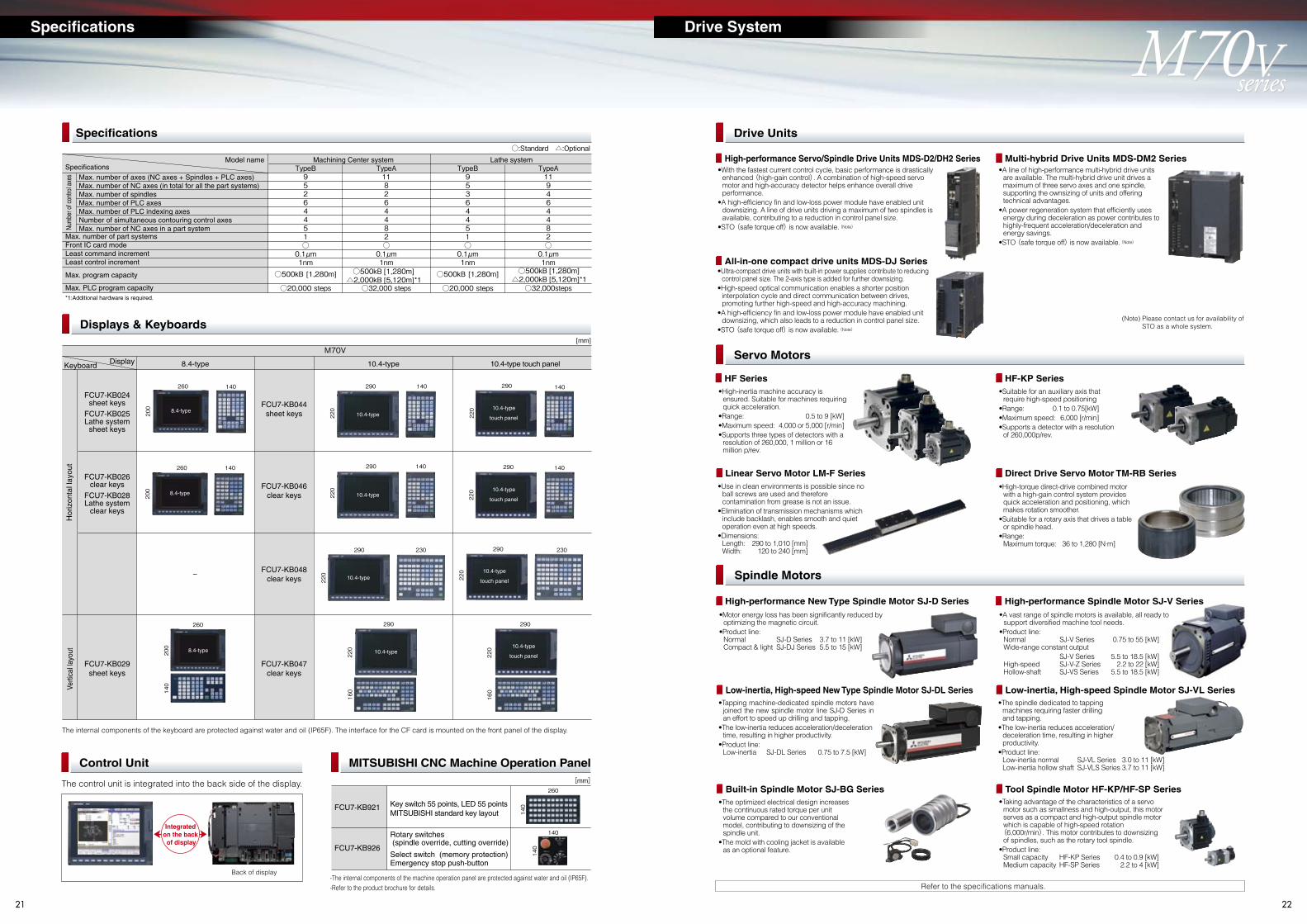
seriesM70VSpecifications
seriesM70VSpecifications
Max. number of axes (NC axes + Spindles + PLC axes)Max. number of NC axes (in total for all the part systems)Max. number of spindlesMax. number of PLC axesMax. number of PLC indexing axesNumber of simultaneous contouring control axesMax. number of NC axes in a part system
Max. number of part systemsFront IC card mode Least command increment Least control increment
Max. program capacity
Max. PLC program capacity
Machining Center system Lathe systemModel nameSpecifications
*1:Additional hardware is required.
TypeB95264451○0.1μm1nm
○500kB [1,280m]
○20,000 steps
TypeB95364451○0.1μm1nm
○500kB [1,280m]
○20,000 steps
TypeA118264482○0.1μm1nm
○32,000 steps
TypeA119464482○0.1μm1nm
○32,000steps
○:Standard △:Optional
Num
ber o
f con
trol a
xes
○500kB [1,280m] △2,000kB [5,120m]*1
○500kB [1,280m] △2,000kB [5,120m]*1
Drive System
Refer to the specifications manuals.
Integrated on the back
of display
Back of display
•With the fastest current control cycle, basic performance is drastically enhanced (high-gain control). A combination of high-speed servo motor and high-accuracy detector helps enhance overall drive performance.
•A high-efficiency fin and low-loss power module have enabled unit downsizing. A line of drive units driving a maximum of two spindles is available, contributing to a reduction in control panel size.
•STO (safe torque off) is now available. (Note)
•A line of high-performance multi-hybrid drive units are available. The multi-hybrid drive unit drives a maximum of three servo axes and one spindle, supporting the ownsizing of units and offering technical advantages.
•A power regeneration system that efficiently uses energy during deceleration as power contributes to highly-frequent acceleration/deceleration and energy savings.
•STO (safe torque off) is now available. (Note)
•Ultra-compact drive units with built-in power supplies contribute to reducing control panel size. The 2-axis type is added for further downsizing.
•High-speed optical communication enables a shorter position interpolation cycle and direct communication between drives, promoting further high-speed and high-accuracy machining.
•A high-efficiency fin and low-loss power module have enabled unit downsizing, which also leads to a reduction in control panel size.
•STO (safe torque off) is now available. (Note)
High-performance Servo/Spindle Drive Units MDS-D2/DH2 Series
All-in-one compact drive units MDS-DJ Series
Multi-hybrid Drive Units MDS-DM2 Series
Drive Units
•High-inertia machine accuracy is ensured. Suitable for machines requiring quick acceleration.
•Range: 0.5 to 9 [kW]•Maximum speed: 4,000 or 5,000 [r/min]•Supports three types of detectors with a
resolution of 260,000, 1 million or 16 million p/rev.
•Suitable for an auxiliary axis that require high-speed positioning
•Range: 0.1 to 0.75[kW]•Maximum speed: 6,000 [r/min]•Supports a detector with a resolution
of 260,000p/rev.
•Use in clean environments is possible since no ball screws are used and therefore contamination from grease is not an issue.
•Elimination of transmission mechanisms which include backlash, enables smooth and quiet operation even at high speeds.
•Dimensions:Length: 290 to 1,010 [mm]Width: 120 to 240 [mm]
•High-torque direct-drive combined motor with a high-gain control system provides quick acceleration and positioning, which makes rotation smoother.
•Suitable for a rotary axis that drives a table or spindle head.
•Range:Maximum torque: 36 to 1,280 [N·m]
•A vast range of spindle motors is available, all ready to support diversified machine tool needs.
•Product line:Normal SJ-V Series 0.75 to 55 [kW]Wide-range constant output
SJ-V Series 5.5 to 18.5 [kW]High-speed SJ-V-Z Series 2.2 to 22 [kW]Hollow-shaft SJ-VS Series 5.5 to 18.5 [kW]
•Motor energy loss has been significantly reduced by optimizing the magnetic circuit.
•Product line:Normal SJ-D Series 3.7 to 11 [kW]Compact & light SJ-DJ Series 5.5 to 15 [kW]
•Tapping machine-dedicated spindle motors have joined the new spindle motor line SJ-D Series in an effort to speed up drilling and tapping.
•The low-inertia reduces acceleration/deceleration time, resulting in higher productivity.
•Product line:Low-inertia SJ-DL Series 0.75 to 7.5 [kW]
•The optimized electrical design increases the continuous rated torque per unit volume compared to our conventional model, contributing to downsizing of the spindle unit.
•The mold with cooling jacket is available as an optional feature.
HF Series
Linear Servo Motor LM-F Series Direct Drive Servo Motor TM-RB Series
High-performance New Type Spindle Motor SJ-D Series High-performance Spindle Motor SJ-V Series
Low-inertia, High-speed New Type Spindle Motor SJ-DL Series
Built-in Spindle Motor SJ-BG Series
HF-KP Series
Servo Motors
Spindle Motors
•The spindle dedicated to tapping machines requiring faster drilling and tapping.
•The low-inertia reduces acceleration/deceleration time, resulting in higher productivity.
•Product line:Low-inertia normal SJ-VL Series 3.0 to 11 [kW]Low-inertia hollow shaft SJ-VLS Series 3.7 to 11 [kW]
Low-inertia, High-speed Spindle Motor SJ-VL Series
•Taking advantage of the characteristics of a servo motor such as smallness and high-output, this motor serves as a compact and high-output spindle motor which is capable of high-speed rotation (6,000r/min). This motor contributes to downsizing of spindles, such as the rotary tool spindle.
•Product line:Small capacity HF-KP Series 0.4 to 0.9 [kW]Medium capacity HF-SP Series 2.2 to 4 [kW]
Tool Spindle Motor HF-KP/HF-SP Series
(Note) Please contact us for availability of STO as a whole system.Displays & Keyboards
MITSUBISHI CNC Machine Operation PanelControl Unit[mm]
FCU7-KB921
FCU7-KB926
The internal components of the keyboard are protected against water and oil (IP65F). The interface for the CF card is mounted on the front panel of the display.
-The internal components of the machine operation panel are protected against water and oil (IP65F).-Refer to the product brochure for details.
The control unit is integrated into the back side of the display.
140
260
140
140
Key switch 55 points, LED 55 pointsMITSUBISHI standard key layout
Rotary switches (spindle override, cutting override)
Select switch (memory protection)Emergency stop push-button
8.4-type
10.4-type
touch panel
10.4-type
touch panel
10.4-type
10.4-type
10.4-type
10.4-type8.4-type
290 140 140
140
290 230
290
220
260
200
8.4-type
260
140
140
200
260
200
140
220
220
220
10.4-type
touch panel
290220
10.4-type
touch panel
290
220
140
290
220
290
220
160
160
290
230
[mm]
FCU7-KB044sheet keys
FCU7-KB024sheet keys
FCU7-KB025Lathe system
sheet keys
FCU7-KB026clear keys
FCU7-KB028Lathe system
clear keys
8.4-type 10.4-type 10.4-type touch panel
M70VDisplayKeyboard
−
FCU7-KB029sheet keys
FCU7-KB047clear keys
FCU7-KB046clear keys
FCU7-KB048clear keys
Hor
izon
tal l
ayou
tVe
rtica
l lay
out
MITSUBISHI CNCM70V Series
CN
C M
70VS
erie
s (EN
GLIS
H)
BN
P-A1218-F[EN
G]
K-KL2-0-C0063-F NA1312 Printed in Japan (MDOC)
Revised publication, effective Dec. 2013.Superseding publication of K-KL2-0-C0063-E Aug. 2013.
Specifications are subject to change without notice.
BNP-A1218-F[ENG](ENGLISH)


![MITSUBISHI CNC M70V Series - Mitsubishi Electric CNC · PDF fileMITSUBISHI CNC M70V Series CNC M70V Series (ENGLISH) BNP-A1218-F[ENG] K-KL2-0-C0063-F NA1312 Printed in Japan (MDOC)](https://static.fdocuments.us/doc/165x107/5a9e449b7f8b9a6a218ced43/mitsubishi-cnc-m70v-series-mitsubishi-electric-cnc-cnc-m70v-series-cnc-m70v-series.jpg)


![MITSUBISHI CNC M70V · PDF fileseries M70V MITSUBISHI CNC M70V Series CNC M70V Series (ENGLISH) BNP-A1218-F[ENG] K-KL2-0-C0063-F NA1312 Printed in Japan (MDOC) Revised publication,](https://static.fdocuments.us/doc/165x107/5aae62e27f8b9a6b308bfab2/mitsubishi-cnc-m70v-m70v-mitsubishi-cnc-m70v-series-cnc-m70v-series-english-bnp-a1218-feng.jpg)


![MITSUBISHI CNC M70V Seriesdl.mitsubishielectric.co.jp/dl/fa/document/catalog/cnc/...series M70V MITSUBISHI CNC M70V Series CNC M70V Series (ENGLISH) BNP-A1218-F[ENG] K-KL2-0-C0063-G](https://static.fdocuments.us/doc/165x107/613c72fc4c23507cb63563e3/mitsubishi-cnc-m70v-series-m70v-mitsubishi-cnc-m70v-series-cnc-m70v-series-english.jpg)