Mitigation strategies for mining in high stress sill ... · to minimise the risk of major ground...
14
Deep Mining 2014 – M Hudyma and Y Potvin (eds) © 2014 Australian Centre for Geomechanics, Perth, ISBN 978-0-9870937-9-0 Deep Mining 2014, Sudbury, Canada 65 Mitigation strategies for mining in high stress sill pillars at Coleman Mine – a case study S Townend Vale Canada Ltd., Canada A Sampson-Forsythe Vale Canada Ltd., Canada Abstract Coleman Mine, a nickel/copper producing mine for Vale in the Sudbury mining district, is a mature mine that has been in continuous production since 1991. This maturity is reflected in the amount of ore that has been mined from several major ore zones and the number of associated sill pillars, many of which are being mined or are about to be mined. In the main nickel orebody one sill pillar is being mined and two more will start to be mined within the next year. In the main copper orebody three sill pillars are being mined with one more about to be mined. With sill pillars, and other diminishing pillars, there are problems with increased stress conditions that have the potential to lead to major seismic events prior to the complete failure of the pillar. This paper describes the different mitigation strategies that have been put in place at Coleman mine to minimise the risk of major ground instabilities caused by high stress conditions associated with sill pillars. 1 Introduction Coleman Mine is located approximately 45 km northwest of Sudbury near the town of Levack. It is one of a series of mines operated by Vale in the Sudbury district on the north rim of the Sudbury Basin (Figure 1). The mine primarily extracts nickel, copper and precious metals from a number of contact orebodies (nickel) and foot wall orebodies (copper and precious metals). Mineralisation is typically associated with discontinuous zones of sublayer norite beneath the south-dipping nickel irruptive structure. The ore lenses are also associated with metamorphosed, re-crystallised and brecciated gneiss and granite breccia. Figure 1 Sudbury Basin map and location of Coleman Mine https://papers.acg.uwa.edu.au/p/1410_02_Townend/
Transcript of Mitigation strategies for mining in high stress sill ... · to minimise the risk of major ground...

Deep Mining 2014 – M Hudyma and Y Potvin (eds) © 2014 Australian Centre for Geomechanics, Perth, ISBN 978-0-9870937-9-0
Deep Mining 2014, Sudbury, Canada 65
Mitigation strategies for mining in high stress sill pillars at Coleman Mine – a case study
S Townend Vale Canada Ltd., Canada
A Sampson-Forsythe Vale Canada Ltd., Canada
Abstract
Coleman Mine, a nickel/copper producing mine for Vale in the Sudbury mining district, is a mature mine that has been in continuous production since 1991. This maturity is reflected in the amount of ore that has been mined from several major ore zones and the number of associated sill pillars, many of which are being mined or are about to be mined. In the main nickel orebody one sill pillar is being mined and two more will start to be mined within the next year. In the main copper orebody three sill pillars are being mined with one more about to be mined. With sill pillars, and other diminishing pillars, there are problems with increased stress conditions that have the potential to lead to major seismic events prior to the complete failure of the pillar. This paper describes the different mitigation strategies that have been put in place at Coleman mine to minimise the risk of major ground instabilities caused by high stress conditions associated with sill pillars.
1 Introduction
Coleman Mine is located approximately 45 km northwest of Sudbury near the town of Levack. It is one of a series of mines operated by Vale in the Sudbury district on the north rim of the Sudbury Basin (Figure 1). The mine primarily extracts nickel, copper and precious metals from a number of contact orebodies (nickel) and foot wall orebodies (copper and precious metals). Mineralisation is typically associated with discontinuous zones of sublayer norite beneath the south-dipping nickel irruptive structure. The ore lenses are also associated with metamorphosed, re-crystallised and brecciated gneiss and granite breccia.
Figure 1 Sudbury Basin map and location of Coleman Mine
https://papers.acg.uwa.edu.au/p/1410_02_Townend/

Mitigation strategies for mining in high stress sill pillars at Coleman Mine S Townend and A Sampson-Forsythe – a case study
66 Deep Mining 2014, Sudbury, Canada
Shaft sinking and level development to access the initial Coleman orebody was carried out between 1966 and 1971. Production began in 1970 and continued until 1982 when the mine was put on standby. The mine was subsequently re-opened in 1987, with the deepening of the shaft to 3440L, and the first ore from Lower Coleman orebody was hoisted in June 1991. Coleman has been in continuous production ever since, bringing into production several other orebodies. As a result of being in production for this length of time, several orebodies have either been completely mined out, such as Lower Coleman, or they have reached a mature stage of development, with more than 65% mined out, such as the top of the Main Orebody (MOB1) and the 153 Orebody. With sill pillars, and other diminishing pillars, there are problems with increased stress conditions that have the potential to lead to major seismic events prior to the complete failure of the pillar.
Presently, Coleman Mine employs two principal mining methods: mechanised cut-and-fill and bulk mining; with cut-and-fill mining as the primary stoping method. Over 70% of Coleman’s production is currently obtained through various cut-and-fill mining techniques, with bulk mining (blasthole/longhole stoping) currently contributing to less than 30% of the overall production. These methods are applied in both the Main Orebody and the 153 Orebody, but with significant differences due to the variation in size and geometry of the two orebodies. Conversion to bulk mining generally occurs during recovery of crown/sill pillars, between mining horizons, or when adverse mining conditions are encountered. This is the case for a number of the Coleman orebodies, specifically dealing with the safe extraction of high stress sill pillars. A number of mitigation strategies have been put in place so as to safely mine these sill pillars.
2 Mitigation strategies
A number of mitigation strategies have been proposed and used at Coleman Mine in the mining of these sill pillars. The main objectives of all these mitigation strategies are to reduce the risk of injury due to worker’s exposure and production loss caused by ground control issues associated with high stresses routinely experienced while mining sill pillars. The mitigation strategies broadly fall into five groups:
Conversion from cut-and-fill to a blasthole stoping method.
Conversion from overhand cut-and-fill to underhand cut-and-fill.
Uppers retreat mining.
De-stress drilling programs.
Combinations of the above four methods, such as conversion to bulk mining plus a de-stress drilling program.
2.1 Conversion from cut-and-fill to blasthole stoping method
The Main Orebody at Coleman Mine was exclusively a post pillar cut-and-fill operation up until 2011 when MOB1 was converted from a post pillar cut-and-fill to a bulk operation, for MOB1 Sill Pillar recovery. From the beginning of cut-and-fill mining, it was recognised that at some point there would be a need to convert to a bulk mining method, as the mining front approached a diminishing sill pillar. The determination of the point of changeover was established early in the life of the orebody (Espley et al. 1996). It was determined that the ground conditions that would be encountered in the upper cuts of the orebody, approaching a previously mined out area above, would increase the risk of injury and/or production loss to an unacceptable level with the continued use of the post pillar cut-and-fill mining method. This transition occurred when the sill pillar had an average vertical thickness of 22 m, a hanging wall to foot wall width that varied between 8 and 110 m at a depth below surface of approximately 1,110 m. Using a different method, such as a bulk blasthole method, with the proper topsill and bottom sill infrastructure in place would sizably reduce the risk of personal injury and production loss. Ideally, for sill pillar recovery, the bulk blasthole mining method can replace cut-and-fill if the dip of the orebody is 55° or greater.
Plenary session
Deep Mining 2014, Sudbury, Canada 67
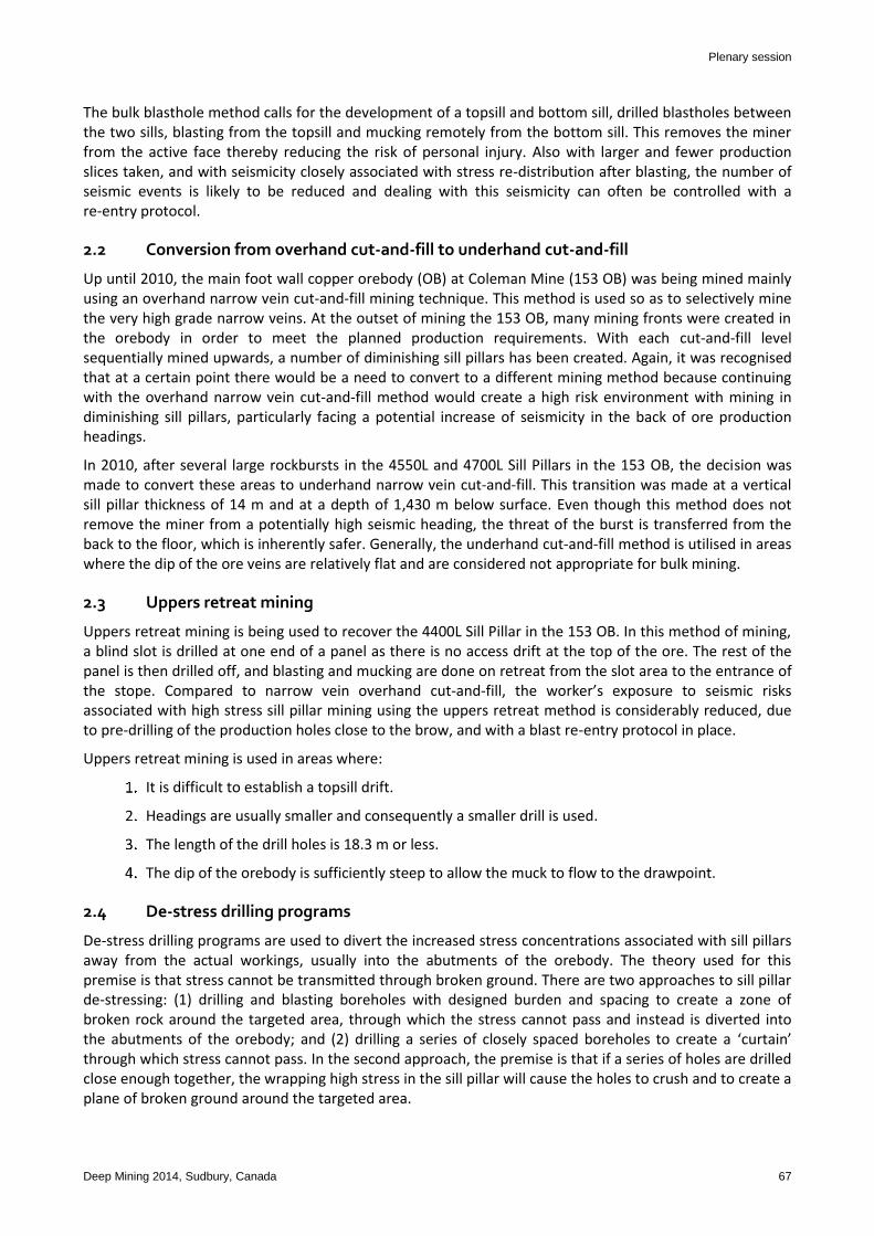
The bulk blasthole method calls for the development of a topsill and bottom sill, drilled blastholes between the two sills, blasting from the topsill and mucking remotely from the bottom sill. This removes the miner from the active face thereby reducing the risk of personal injury. Also with larger and fewer production slices taken, and with seismicity closely associated with stress re-distribution after blasting, the number of seismic events is likely to be reduced and dealing with this seismicity can often be controlled with a re-entry protocol.
2.2 Conversion from overhand cut-and-fill to underhand cut-and-fill
Up until 2010, the main foot wall copper orebody (OB) at Coleman Mine (153 OB) was being mined mainly using an overhand narrow vein cut-and-fill mining technique. This method is used so as to selectively mine the very high grade narrow veins. At the outset of mining the 153 OB, many mining fronts were created in the orebody in order to meet the planned production requirements. With each cut-and-fill level sequentially mined upwards, a number of diminishing sill pillars has been created. Again, it was recognised that at a certain point there would be a need to convert to a different mining method because continuing with the overhand narrow vein cut-and-fill method would create a high risk environment with mining in diminishing sill pillars, particularly facing a potential increase of seismicity in the back of ore production headings.
In 2010, after several large rockbursts in the 4550L and 4700L Sill Pillars in the 153 OB, the decision was made to convert these areas to underhand narrow vein cut-and-fill. This transition was made at a vertical sill pillar thickness of 14 m and at a depth of 1,430 m below surface. Even though this method does not remove the miner from a potentially high seismic heading, the threat of the burst is transferred from the back to the floor, which is inherently safer. Generally, the underhand cut-and-fill method is utilised in areas where the dip of the ore veins are relatively flat and are considered not appropriate for bulk mining.
2.3 Uppers retreat mining
Uppers retreat mining is being used to recover the 4400L Sill Pillar in the 153 OB. In this method of mining, a blind slot is drilled at one end of a panel as there is no access drift at the top of the ore. The rest of the panel is then drilled off, and blasting and mucking are done on retreat from the slot area to the entrance of the stope. Compared to narrow vein overhand cut-and-fill, the worker’s exposure to seismic risks associated with high stress sill pillar mining using the uppers retreat method is considerably reduced, due to pre-drilling of the production holes close to the brow, and with a blast re-entry protocol in place.
Uppers retreat mining is used in areas where:
It is difficult to establish a topsill drift.
Headings are usually smaller and consequently a smaller drill is used.
The length of the drill holes is 18.3 m or less.
The dip of the orebody is sufficiently steep to allow the muck to flow to the drawpoint.
2.4 De-stress drilling programs
De-stress drilling programs are used to divert the increased stress concentrations associated with sill pillars away from the actual workings, usually into the abutments of the orebody. The theory used for this premise is that stress cannot be transmitted through broken ground. There are two approaches to sill pillar de-stressing: (1) drilling and blasting boreholes with designed burden and spacing to create a zone of broken rock around the targeted area, through which the stress cannot pass and instead is diverted into the abutments of the orebody; and (2) drilling a series of closely spaced boreholes to create a ‘curtain’ through which stress cannot pass. In the second approach, the premise is that if a series of holes are drilled close enough together, the wrapping high stress in the sill pillar will cause the holes to crush and to create a plane of broken ground around the targeted area.

Mitigation strategies for mining in high stress sill pillars at Coleman Mine S Townend and A Sampson-Forsythe – a case study
68 Deep Mining 2014, Sudbury, Canada
This paper will focus on the second approach for sill pillar de-stressing. For this de-stress drilling program, the key design parameters are the size of the holes, which may be dependent on the drilling equipment available, and the hole spacing. Optimally closely spaced holes will ensure good results but may require a lot of drilling resources, while widely spaced holes will use less drilling resources but will have a lower likelihood of achieving the purpose of creating the fractured ground.
3 Case studies
3.1 Conversion from cut-and-fill to blasthole stoping method in the main orebody
The upper portion of Coleman’s Main Orebody, known as MOB1, is located immediately below the previously mined Glencore (formerly Falconbridge) Fraser Mine Nickel Zone orebody, and just above MOB2 (Figure 2). An agreement between the then Inco and Falconbridge mining companies created a horizontal mining boundary between the two operations. The stopes above the boundary were mined by Falconbridge, and an engineered sill mat was placed on the floor of the bulk stopes, at the boundary. Inco started mining the orebody below the boundary as a cut-and-fill mining operation, for more than 15 cuts, at which point the mining in MOB1 was converted to a bulk operation. The respective depths below surface of the original sill elevations as shown in figure 2 are Fraser at 1,090 m, MOB1 at 1,210 m, MOB2 at 1,300 m and MOB3 at 1,360 m.
Figure 2 General view of the Main Orebody (MOB1, MOB2 and MOB3) – looking north
Numerical modelling results from a 2007 geomechanics review (Golder Associates Ltd. 2007) concurred with the findings from the initial MOB1 Geomechanics study (Espley et al. 1996), which indicated that an extensive ground support system or an alternative crown recovery method would be required when the thickness of MOB1 Crown, beneath Fraser Mine, was less than or equal to 30 m. When mining on Cut 13 in MOB1, ground control assessments showed that ground conditions were rapidly deteriorating and that a conversion to bulk mining was needed. The cut-and-fill operation was converted to blasthole stoping at Cut 15 on the east side, and Cut 16 in the central part and west side of MOB1. Later modelling of MOB1 Crown/Sill Pillar (Itasca 2012) showed that, with the exception of the west side, for the majority of the pillar there would be no significant high stress issues. The only anticipated high stress and rockbursting potential issues would be with mining of the narrow western limb of the MOB1 Crown (Figure 3).

Plenary session
Deep Mining 2014, Sudbury, Canada 69
Figure 3 MOB1 crown pillar mining model plan view, showing areas of expected high stress at the abutments and in the Western Limb (Itasca 2012)
Figure 4 MOB1 crown pillar mining to date
As indicated in Figure 4, where the dark shaded areas represent stopes that have been mined and filled, bulk mining in MOB1 has progressed with no major ground control issues. Although there has been no substantial mining in the western limb area, there was a moderate increase in stress level after the final blast in the most western stope. As a result, the need to drill a de-stress curtain may still be required and the situation is being monitored.

Mitigation strategies for mining in high stress sill pillars at Coleman Mine S Townend and A Sampson-Forsythe – a case study
70 Deep Mining 2014, Sudbury, Canada
3.2 Conversion from overhand cut-and-fill to underhand cut-and-fill in 153 Orebody
The 153 Orebody is a vein type high value F/W copper deposit that is mined using a narrow vein cut-and-fill mining method. The orebody was initially divided into a number of levels and panels on each level from which mining progressed upwards to the level above. As each overhand cut-and-fill level is mined upwards towards the sill above, the crown is diminished and sill pillars are created (Figure 5).
Figure 5 153 Orebody mining to date showing the remaining sill pillars
Currently there are four sill pillars simultaneously being mined in the 153 OB: 4400L Sill Pillar (bulk mining/uppers) at 1,360 m below surface; the 4550L and 4700L Sill Pillars (underhand cut-and-fill) respectively at 1,400 and 1,450 m below surface, and 4810L Sill (overhand cut-and-fill) at 1,510 m below surface. Recovery of these diminishing sill pillars can be challenging due the high stress problems associated with mining in such pillars. Critical pillar thickness could vary from 14-16 m depending on the dip of the ore. Based on previous experience, with sill pillar mining in narrow vein cut-and-fill stopes, the narrow, single vein ore zones are of major concern because these areas normally take longer to yield. In the case of the 4550L and 4700L Sill Pillars, the core of the pillar in the narrow zones is expected to fail within the last two to three cuts in the crown/sill (i.e. 4.5-8.2 m sill pillar thickness); if it has not already failed.
As a general guideline, when a sill pillar is about 20 m thick the continued suitability of the overhand cut-and-fill mining method should be re-evaluated, although this thickness will vary somewhat depending on the width of the orebody. Reason being that, as overhand cut-and-fill mining progressed upwards, from level to level, the vertical thickness of the crown pillar below the above sill cut becomes progressively smaller. These diminishing pillars will suffer the high horizontal, mining-induced stresses, and the stiff host rock often fails catastrophically, causing major ground control problems and safety issues. Depending on ground conditions, each horizon, or level, may eventually be converted to bulk mining and/or underhand cut-and-fill for sill pillar extraction as these pillars between the mining zones are diminished. If a conversion to underhand cut-and-fill is made then new mining accesses are developed under the previously mined and filled sill cut of the level above and then mining progresses downwards towards the existing overcuts

Plenary session
Deep Mining 2014, Sudbury, Canada 71
coming up from the level below. If the dip of the ore vein is greater than 50°, bulk mining (also known as VRM, blasthole or longhole stoping) is the preferred mining method for these narrow vein ore zones, in high stress conditions.
In 2009, a geomechanics study for the 153 Orebody – 4550 and 4700 Levels – was completed by Itasca and Vale’s Mines Technical Support Group (Itasca 2009) to examine suitable mining strategies for the crown pillars of these two levels. While mining on Cut 14 in 4550L Block 2, it was obvious from the elevated levels of seismic activity that the risk of exposure to a significant seismic event was increasing and that a change of mining method from the regular overhand cut-and-fill was required.
In the case of 4550L Block 2, the mining method was switched from overhand cut-and-fill to underhand cut-and-fill, with the first underhand cut-and-fill horizon on 4550L Cut 17 (Figure 6). The conversion to underhand cut-and-fill was taken when the vertical thickness of the sill pillar had diminished to 11 m. The first underhand cut-and-fill slice was to be mined under a 10:1 cemented sand fill (non-reinforced sill mat), that was placed more than 10 years ago. Therefore, prior to developing beneath the backfill, the strength and integrity of the fill had to be determined. A diamond drill program, for sill mat drilling in the 153 Orebody, was completed in early 2011, and several diamond drill holes were strategically drilled into the sill cuts of 4400L, 4550L and 4810L. The minimum backfill strength (unconfined compressive strength) required for a stable 4.5 m back span is 1.0 MPa (Stone 1993).
To mitigate the risk of potential backfill failure during mining of the first underhand cut-and-fill stope (with no engineered sill mat in the back), the following controls were put in place:
Take short rounds (~1.8 m) at the start of mining under the 10:1 sand fill. The round length could be increased later, if the backfill was found to be sufficiently competent.
Drill back holes ~0.5 m below the 10:1 backfill sill, to reduce blast damage to the backfill.
Maintain a maximum mining width of 4.5 m.
An engineered sill mat would be placed in each heading after completion of mining on the current cut, in preparation of mining subsequent underhand cut-and-fill headings (Figure 7).
Figure 6 Underhand cut-and-fill mining in the 4550L sill pillar in 153 Orebody

Mitigation strategies for mining in high stress sill pillars at Coleman Mine S Townend and A Sampson-Forsythe – a case study
72 Deep Mining 2014, Sudbury, Canada
Figure 7 Mining under the Gabion Sill Mat in 4550L Block 2, Cut 16, underhand cut-and-fill heading in 153 Orebody
Compared to overhand cut-and-fill, the underhand cut-and-fill mining method is generally a safer method when mining in high stress sill pillars because it reduces the risks of worker exposure to high stress conditions, in the back and foot wall shoulder. Also, with an engineered sill mat, underhand mining is safer because the miners are always working beneath reinforced cemented-backfill which is less likely to fail during or after a rockburst. With underhand cut-and-fill mining, the high mining-induced stresses are mainly concentrated in the hanging wall and floor area of the current cut, while the stresses in the immediate foot wall area are relatively low because of shielding. As a result, the main foot wall vein drifts, foot wall shoulder and stope accesses should be stress shadowed and not require the same amount of enhanced ground support as needed in the case of overhand cut-and-fill mining. Mining from foot wall to hanging wall is the preferred mining sequence. In addition, several other mines such as Lucky Friday, Galena and Stillwater in the United States and Xstrata Copper in Canada have successfully used underhand cut-and-fill mining in narrow vein situation to drastically reduce the exposure of workers to significant seismic events (Pakalnis et al. 2005).
Since converting to an underhand method for 4550L Block 2, the stress problems have not disappeared completely and at times extra measures in the form of face de-stress drilling have been employed during mining of Cut 17, which was completed in 2013. Although progress has been slow in 4550L Block 2 and at times the headings were shut down due to seismic activity, with the use of shotcrete as a primary support the first underhand cut has been mined successfully with only a small number of ground control incidents. Mining of Cut 16 (the second underhand cut) has been a bit more challenging with major issues of floor heaving after increased seismicity and two large magnitude events, as the 4550L Sill Pillar continues to yield. Consequently, a decision was made to de-stress the 8.2 m thick sill pillar, to effectively move the stress away from the active mining areas. In the case of the 4700L Block 2 sill pillar, there have been no major stress problems since underhand cut-and-fill mining started about two years ago.
3.3 De-stress drilling program on 4810L in the 153 Orebody
On 4810L the dip of the 153 Orebody is relatively flat, which precludes the use of uppers retreat mining method to recover the sill pillar. This then leaves the practical remaining options of underhand cut-and-fill mining, or overhand cut-and-fill mining, with a de-stress drill curtain to deflect the stresses to the orebody abutments. Based on the known deficiencies of the underhand method compared with the

Plenary session
Deep Mining 2014, Sudbury, Canada 73
overhand method a business case was prepared that showed that drilling a de-stress curtain, even at a cost of CAD1.5 m, and continuing with the overhand method to complete sill pillar mining provided a greater net present value than converting to the underhand method. Due to the high value of the ore on this level any reduction in the production rate has a large impact on cash flow.
Having decided on drilling a de-stress curtain the next question was what should be the size and spacing of the holes, and whether they should be just drill holes or blasted drill holes. It was decided that 165 mm non-blasted relief holes, spaced 0.6 m apart would be used (Figure 8). The basis for the design for the unblasted hole layout was to give each hole a length of influence toward the next hole of three times the diameter of the hole (3 × 16.5 cm) with some degree of overlap. This resulted in a spacing of 0.6m. The lengths and dips of these stress relief holes were variable to match the ore outline at the foot wall, and the holes were drilled just above the floor elevation of 4700L Cut 1. It was essential to have a curtain of closely spaced drilled holes to cut off the high subhorizontal stress in the 4810L Sill Pillar, since the stress relief holes would not be blasted.
Preliminary indications of the high stresses in this area were confirmed by the number of times that the rods and hammers had become stuck, and had to be abandoned due to squeezing ground conditions. Based on observations of the integrity of the drilled holes, and readings from stress cells installed in the foot wall, it was concluded that the de-stress curtain was effective, in that the ground around the holes was crushing (Figure 9), and the stress levels were dropping (Figure 10) after completion of the stress relief holes. Another validation of this conclusion is that there have been no large magnitude events or significant high stress issues in the 4810 Sill Pillar since completion of the stress relief holes in Blocks 4 and 2. The drilling of the de-stress curtain has allowed for the continued use of overhand cut-and-fill, up to the final cut below the sill on 4700L.
With completion of the de-stress drilling program on 4810L, it is expected that the stress will redistribute to the east and west abutments, and below and above the 4810L, to the other sill pillars. As a result, additional controls and enhanced ground support must be strategically installed in the 4945L Access and Kiruna Ramp Intersections prior to mining the next cuts on the 4810 and 4945 Levels.
Figure 8 De-stress drilling in 4810L Block 4 -1W foot wall vein in 153 Orebody

Mitigation strategies for mining in high stress sill pillars at Coleman Mine S Townend and A Sampson-Forsythe – a case study
74 Deep Mining 2014, Sudbury, Canada
Figure 9 De-stress holes in 4810L Block 4 -1W showing evidence of stress relief
Figure 10 Stress change in the foot wall area of 4810L Block 4 -1W, showing significant stress drop after drilling of the stress relief/de-stress holes
3.4 Combination of de-stress drilling and conversion to bulk mining in MOB2 - M2 in the main orebody
The mining geometry for MOB2 is very similar to MOB1 in that at the east side of the orebody the distance from the hanging wall to foot wall is significant enough to create a similar stress condition to that experienced with mining of the MOB1 sill pillar (Figure 3). A geomechanical assessment of the sill pillars in MOB2 and MOB3, conducted in 2010, concluded that “increasing induced stress and confinement in the west ore zones result in burst prone and difficult mining conditions” (Hosseini 2010). The predicted highly
Plenary session
Deep Mining 2014, Sudbury, Canada 75
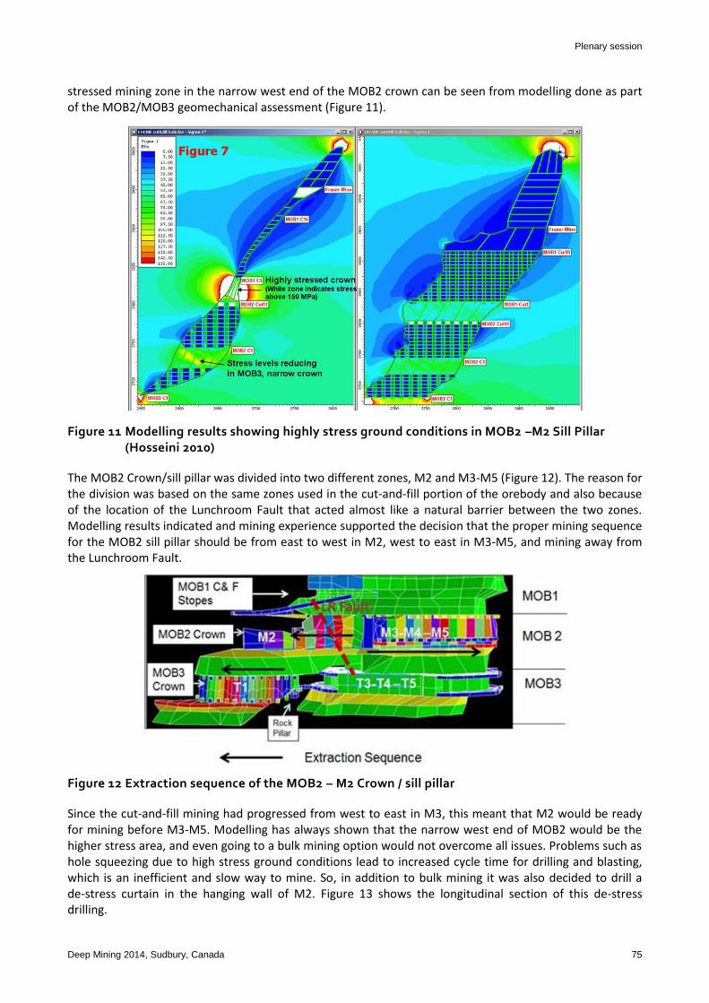
stressed mining zone in the narrow west end of the MOB2 crown can be seen from modelling done as part of the MOB2/MOB3 geomechanical assessment (Figure 11).
Figure 11 Modelling results showing highly stress ground conditions in MOB2 –M2 Sill Pillar (Hosseini 2010)
The MOB2 Crown/sill pillar was divided into two different zones, M2 and M3-M5 (Figure 12). The reason for the division was based on the same zones used in the cut-and-fill portion of the orebody and also because of the location of the Lunchroom Fault that acted almost like a natural barrier between the two zones. Modelling results indicated and mining experience supported the decision that the proper mining sequence for the MOB2 sill pillar should be from east to west in M2, west to east in M3-M5, and mining away from the Lunchroom Fault.
Figure 12 Extraction sequence of the MOB2 – M2 Crown / sill pillar
Since the cut-and-fill mining had progressed from west to east in M3, this meant that M2 would be ready for mining before M3-M5. Modelling has always shown that the narrow west end of MOB2 would be the higher stress area, and even going to a bulk mining option would not overcome all issues. Problems such as hole squeezing due to high stress ground conditions lead to increased cycle time for drilling and blasting, which is an inefficient and slow way to mine. So, in addition to bulk mining it was also decided to drill a de-stress curtain in the hanging wall of M2. Figure 13 shows the longitudinal section of this de-stress drilling.

Mitigation strategies for mining in high stress sill pillars at Coleman Mine S Townend and A Sampson-Forsythe – a case study
76 Deep Mining 2014, Sudbury, Canada
Figure 13 Longitudinal section showing MOB2 – M2 de-stress drilling
Currently (April 2014) the first bulk stope is being mined in the M2 ore zone. Some problems have been associated with drilling and reaming of the raise bore slot for the first stope. This can be partially attributed to some of the stress wrapping around the east end of the de-stress curtain prior to mining out a series of stopes from hanging wall to foot wall, which was a recommendation in the mining sequence that would also neutralise the effect of the Lunchroom Fault.
However some anecdotal evidence of the effect of the de-stress curtain was provided by the lack of stuck rods while drilling the first stope and also an improvement in the conditions in driving the hanging wall bottom sill drift (0846 Sill Drift). Conditions in this drift began to deteriorate while it was being driven and the decision was made to suspend development until after the completion of the de-stress curtain to a point where the remaining drift would fall within the stress shadow. Upon resumption of the development, the ground conditions encountered were much better. It remains to be seen whether this program will be as successful as the program in the 153 Orebody on 4810L. The height differential between these two examples makes it difficult to compare. Although the length of the drill holes are comparable, the shallow dip of the de-stress holes in the 153 Orebody makes the actual vertical height of the 4810L sill pillar much less than M2 sill pillar. A review of the location and magnitude of past and future seismic events will provide a clear indication of the effectiveness of the program.
4 Conclusions
In several areas at Coleman Mine there has been a need to mine highly stressed sill pillars. For each of the case studies cited in this paper a change in mining method was necessary to safely extract the sill pillar. It was recognised that continuing with the established mining method, whether it was post pillar cut-and-fill or narrow vein cut-and-fill, a situation would be reached where the induced stresses would significantly increase the risk of seismicity, broken ground conditions and the possibility of injury or damage to equipment and excavation. This was not an acceptable situation for Management at Coleman; therefore a change in mining method was required.
Initial indications from the mining that has taken place in MOB1 have shown that bulk mining has eliminated the risk of increased seismic activity associated with a diminishing sill pillar compared to the continuation of post pillar cut-and-fill mining. However the west end of MOB1 would be subject to high risk of seismicity due to its geometry and location.

Plenary session
Deep Mining 2014, Sudbury, Canada 77
The conversion from overhand cut-and-fill to underhand cut-and-fill on 4550L and 4700L in the 153 Orebody has reduced the severity of seismic risk by removing the source of the stress from being in the back and shoulders to the floor of the development.
As with the bulk mining in MOB1, the conversion from a cut-and-fill mining method to a bulk mining for the uppers retreat on 4400L in the 153 Orebody has reduced workers’ exposure to major seismicity conditions by mining several cuts at once, which directs the highest risk for seismic activity above the uppers zone.
Based on results from instrumentation and underground observations, it is obvious that the drilling of the de-stress curtain on 4810L in the 153 Orebody has been effective in moving the stress from the active working areas to the orebody abutments. It has also been shown that being able to carry on mining using the more efficient overhand method more than justified the cost of drilling a de-stress curtain.
For the last case study, with M2 sill pillar de-stressing, the preliminary results are inconclusive. However, early indications such as the improved ground conditions in the development of the 0846 Sill Drift and the lack of stuck rods in the stope while drilling suggest that the limited de-stress drilling that has been done so far has been effective.
Acknowledgement
The authors thank Samantha Espley, Steve Runnalls and Andre Lauzon at Vale’s Ontario Operations for granting permission to write this paper. Acknowledgement is also extended to the management and employees of Coleman Mine for their input, consideration and implementation of the stress mitigation methods put in place.
References
Espley, S, Courchesne, T & Castro, L 1996, McCreedy East Mine Main Zone: Rock Mechanics Study, Inco Mines research report, Inco Ltd.
Golder Associates Ltd. 2007, MOB1 – Sill Pillar McCreedy East Mine, report submitted to Vale, Golder Associates Ltd., Sudbury. Hosseini, Z 2010, Geomechanics Study: MOB2 & MOB3 Sill Pillars at Coleman Mine, Vale internal report. Itasca Consulting Canada, Inc. 2009, 153 Orebody Mining and Geotechnical study for 4550 and 4700 Levels Crown Pillar Recovery,
report submitted to Vale, Itasca Consulting Canada, Inc., Sudbury. Itasca Consulting Canada, Inc. 2012, Coleman Mine MOB1 Numerical Modelling Results, report submitted to Vale, Itasca Consulting
Canada, Inc., Sudbury. Pakalnis, R, Caceres, C, Clapp, K, Morin, M, Brady, T, Williams, T, Blake, W & MacLaughlin, M 2005, ‘Design Spans – Underhand
Cut-and-fill Mining’, presentation at the 107th CIM-AGM, Toronto, April 2005. Stone, DMR 1993, ‘The optimization of mix designs for cemented rockfill’, in HW Glen (ed.), Proceedings of the Fifth International
Symposium on Mining with Backfill, South African Institute of Mining and Metallurgy, Johannesburg, pp. 249-253.

Mitigation strategies for mining in high stress sill pillars at Coleman Mine S Townend and A Sampson-Forsythe – a case study
78 Deep Mining 2014, Sudbury, Canada