
Mitigating EMI Signal Injection Attacks against Analog Sensors · PDF fileGhost Talk:...
15
Ghost Talk: Mitigating EMI Signal Injection Attacks against Analog Sensors Denis Foo Kune * , John Backes † , Shane S. Clark ‡ , Daniel Kramer, MD § , Matthew Reynolds, MD ¶ , Kevin Fu * , Yongdae Kim k , and Wenyuan Xu ** * University of Michigan † University of Minnesota, Twin Cities ‡ University of Massachusetts Amherst § Beth Israel Deaconess Medical Center, Harvard Medical School ¶ Harvard Clinical Research Institute k Korea Advanced Institute of Science and Technology (KAIST) ** University of South Carolina Abstract—Electromagnetic interference (EMI) affects cir- cuits by inducing voltages on conductors. Analog sensing of signals on the order of a few millivolts is particularly sensitive to interference. This work (1) measures the susceptibility of analog sensor systems to signal injection attacks by intentional, low-power emission of chosen electromagnetic waveforms, and (2) proposes defense mechanisms to reduce the risks. Our experiments use specially crafted EMI at varying power and distance to measure susceptibility of sensors in implantable medical devices and consumer electronics. Results show that at distances of 1–2 m, consumer electronic devices containing microphones are vulnerable to the injection of bogus audio signals. Our measurements show that in free air, intentional EMI under 10 W can inhibit pacing and induce defibrillation shocks at distances up to 1–2 m on implantable cardiac elec- tronic devices. However, with the sensing leads and medical devices immersed in a saline bath to better approximate the human body, the same experiment decreased to under 5 cm. Our defenses range from prevention with simple analog shielding to detection with a signal contamination metric based on the root mean square of waveform amplitudes. Our con- tribution to securing cardiac devices includes a novel defense mechanism that probes for forged pacing pulses inconsistent with the refractory period of cardiac tissue. Keywords-Attacks and defenses; embedded systems security; hardware security; analog sensors. I. I NTRODUCTION Analog sensors have increasingly become an indispens- able part of many modern systems, ranging from smart- phones to medical devices to closed-loop control systems. The application layer running on these systems makes critical decisions, including actuation based on inputs from sensors including temperature, flow, position, electrocardio- grams, electroencephalograms, and microphones. Unfortu- nately, analog sensors sensitive to electromagnetic interfer- ence (EMI) can provide an unchecked entry point into other- wise protected systems, allowing an attacker to manipulate sensor readings without changing the underlying physical Lead student author: D. Foo Kune Corresponding faculty authors: K. Fu, Y. Kim, W. Xu Device Network Traffic Software Updates Sensor Readings Figure 1. Common device architectures implicitly trust sensed inputs. An attacker controlling sensed inputs can thus manipulate the application layer. phenomena. The modified sensed data can appear directly at a device’s application layer, bypassing common security mechanisms (Figure 1) and giving the attacker some level of control over the system. EMI affects circuits by inducing voltages on conductors — an effect also known as “back-door” coupling [1], where components become unintentional antennas capturing EMI radiation [2], [3]. EMI sources can be divided into inten- tional or unintentional, and low-power or high-power. There is abundant work devoted to unintentional or high-power EMI, but the effect of intentional low-power EMI for analog signal injection has yet to be explored. Unintentional high- power EMI sources, such as lightning strikes, electric trains, transformers [4], and sometimes communicating radios [5] are known to have an impact on modern circuits and analog sensors. Unintentional low-power leaks can allow eavesdrop- ping on a system [6] and unintentional low power sources are also well known and accounted for in circuit designs [2]. In medicine unintentional high power EMI radiated from tools used for procedures like electrocautery [7] and from MRIs [8], [9] can affect cardiac implantable electrical de- vices (CIEDs). In addition, cell phones and other modern transmission devices have been investigated for their effect on CIEDs [10], [11], [12] and risks to patients. Intentional EMI at high power can disable an adversary’s electronic components [13], [1], [14], [15]; intentional EMI
Transcript of Mitigating EMI Signal Injection Attacks against Analog Sensors · PDF fileGhost Talk:...

Ghost Talk: Mitigating EMI Signal Injection Attacks against Analog Sensors
Denis Foo Kune∗, John Backes†, Shane S. Clark‡, Daniel Kramer, MD§, Matthew Reynolds, MD¶,Kevin Fu∗, Yongdae Kim‖, and Wenyuan Xu∗∗
∗University of Michigan†University of Minnesota, Twin Cities‡University of Massachusetts Amherst
§Beth Israel Deaconess Medical Center, Harvard Medical School¶Harvard Clinical Research Institute
‖Korea Advanced Institute of Science and Technology (KAIST)∗∗University of South Carolina
Abstract—Electromagnetic interference (EMI) affects cir-cuits by inducing voltages on conductors. Analog sensing ofsignals on the order of a few millivolts is particularly sensitiveto interference. This work (1) measures the susceptibility ofanalog sensor systems to signal injection attacks by intentional,low-power emission of chosen electromagnetic waveforms, and(2) proposes defense mechanisms to reduce the risks.
Our experiments use specially crafted EMI at varying powerand distance to measure susceptibility of sensors in implantablemedical devices and consumer electronics. Results show thatat distances of 1–2 m, consumer electronic devices containingmicrophones are vulnerable to the injection of bogus audiosignals. Our measurements show that in free air, intentionalEMI under 10 W can inhibit pacing and induce defibrillationshocks at distances up to 1–2 m on implantable cardiac elec-tronic devices. However, with the sensing leads and medicaldevices immersed in a saline bath to better approximate thehuman body, the same experiment decreased to under 5 cm.
Our defenses range from prevention with simple analogshielding to detection with a signal contamination metric basedon the root mean square of waveform amplitudes. Our con-tribution to securing cardiac devices includes a novel defensemechanism that probes for forged pacing pulses inconsistentwith the refractory period of cardiac tissue.
Keywords-Attacks and defenses; embedded systems security;hardware security; analog sensors.
I. INTRODUCTION
Analog sensors have increasingly become an indispens-able part of many modern systems, ranging from smart-phones to medical devices to closed-loop control systems.The application layer running on these systems makescritical decisions, including actuation based on inputs fromsensors including temperature, flow, position, electrocardio-grams, electroencephalograms, and microphones. Unfortu-nately, analog sensors sensitive to electromagnetic interfer-ence (EMI) can provide an unchecked entry point into other-wise protected systems, allowing an attacker to manipulatesensor readings without changing the underlying physical
Lead student author: D. Foo KuneCorresponding faculty authors: K. Fu, Y. Kim, W. Xu
Device
Network Traffic
Software Updates
Sensor Readings
Figure 1. Common device architectures implicitly trust sensed inputs. Anattacker controlling sensed inputs can thus manipulate the application layer.
phenomena. The modified sensed data can appear directlyat a device’s application layer, bypassing common securitymechanisms (Figure 1) and giving the attacker some levelof control over the system.
EMI affects circuits by inducing voltages on conductors— an effect also known as “back-door” coupling [1], wherecomponents become unintentional antennas capturing EMIradiation [2], [3]. EMI sources can be divided into inten-tional or unintentional, and low-power or high-power. Thereis abundant work devoted to unintentional or high-powerEMI, but the effect of intentional low-power EMI for analogsignal injection has yet to be explored. Unintentional high-power EMI sources, such as lightning strikes, electric trains,transformers [4], and sometimes communicating radios [5]are known to have an impact on modern circuits and analogsensors. Unintentional low-power leaks can allow eavesdrop-ping on a system [6] and unintentional low power sourcesare also well known and accounted for in circuit designs [2].In medicine unintentional high power EMI radiated fromtools used for procedures like electrocautery [7] and fromMRIs [8], [9] can affect cardiac implantable electrical de-vices (CIEDs). In addition, cell phones and other moderntransmission devices have been investigated for their effecton CIEDs [10], [11], [12] and risks to patients.
Intentional EMI at high power can disable an adversary’selectronic components [13], [1], [14], [15]; intentional EMI

can also be used to inject faults into digital logic, leadingto security violations [16], but this typically requires sev-eral volts of induced potential to succeed. Analog circuits,however, operating on the order of a few millivolts, can bevulnerable to interference at much lower energy levels andcan allow the injection of forged sensor readings.
This work focuses on the signal injection with intentionallow-power EMI on analog sensors. We analyze the rootcauses that enable signal injection on analog sensors, demon-strate that several commodity sensors are vulnerable to ourEMI attacks, and investigate defense strategies.
Low-Power EMI Attack Analysis. Using back-doorcoupling, we design two types of EMI attacks:1. Baseband EMI attacks inject signals within the samefrequency band as sensor readings. Thus they are effectiveagainst analog sensors equipped with filters that attenuatesignals outside intended frequency bands.2. Amplitude-modulated EMI attacks modulate an attacksignal on a carrier within the frequency band to which thevictim’s analog sensors respond. Since the frequency of theEMI signal can match to the resonant frequency of a sensor,a successful attack requires a lower transmission power thanbaseband EMI attacks.
EMI Attack Validation. We demonstrated EMI attackson medical devices monitoring electrograms and on com-modity electronics using microphones. Specifically, despiteproper filters in CIEDs, we successfully injected forgedsignals in leads in free air, causing pacing inhibition anddefibrillation from 1 to 2 m away by transmitting at about10 W and using a simple whip monopole antenna. With thedevice submerged in saline solution, the results decreasedto under 5 cm. We also found that many commodity deviceslack filters and are vulnerable to high frequency EMI signals.Using a transmitter with a power output of less than 100 mW,we were able to inject audio signals on microphones at adistance of up to 1 to 2 m. Our audio signals consisted ofsimple sinusoids, Dual-Tone Multiple Frequency (DTMF)signals commonly used in modern telephony, and arbitrarywaveforms such as human speech and music.
Mitigation. While defenses against EMI attacks exist, wenonetheless found many devices vulnerable. We applied andmeasured the attenuation of our attack signal by known de-fenses including shielding, filtering and common mode noiserejection. Those techniques ameliorate but do not eliminatethe injected EMI signals. Thus, we propose software-baseddefenses that take advantage of the intended signal’s physicalproximity to the sensor and the ability to elicit feedback todiscriminate between real and forged signals.
II. SENSOR AND EMI ATTACK OVERVIEW
A. Threat model
This work considers an adversary that has prior knowl-edge of the device under attack, including the specific makeand model of the device — information that could be
Zone 2
Zone 1
1
1
0.01 100 10 000
100
0.01
0.001
Zone 3
Frequency (kHz)
Amplitu
de (m
V p-‐p)
Figure 2. Safe zone (Zone 2) for operation of CIEDs from ANSI/AAMIPC69-2007 [17]. Emissions in Zone 1, even at low amplitudes, have a higherrisk of interference because it is the sensing region for those devices.
obtained via other channels including social engineering. Fordevices in widespread use, the attacker may even possess adevice of the same model.
In addition, we assume that an adversary has access tocommodity hardware (e.g., laptops, audio amplifiers, andsignal generators) sufficient to mount attacks from a distanceof several meters. Although the range can be increased withspecialized equipment, this work aims to demonstrate theattack feasibility and focuses on techniques that can bypassfilters and common defenses; we do not directly address thetransmission power. A well-funded adversary could launchlonger-range attacks using high power amplifiers and high-gain antennas.
The adversary’s goal is to manipulate sensor readingsby injecting signals directly into the analog circuit withoutaltering the sensed physical phenomenon. Thus, if s(t) rep-resents the readings produced by the sensor in isolation, theadversary’s goal is to inject a malicious signal, m(t), suchthat the sensor readings become s′(t) = m(t) + s(t), wherem(t) >> s(t), and m(t) dominates with s′(t) ≈ m(t).
B. Sensor background
Sensors are transducers that convert physical phenomenasuch as light, temperature, or sound into electrical signals.Cardiac activity produces electrical signals that can besensed directly. This work considers sensors that producevoltage signals in the Very Low Frequency (VLF) band(1 Hz –30 kHz) or lower. The output is then amplified, pos-sibly filtered, and digitized before delivery to an applicationrunning on the microprocessor (Figure 3). The frequencyrange of the output is the sensor’s baseband. Sensors maybe sensitive to EMI in their baseband and without filters,they may be sensitive to EMI outside of the basebandtoo. This work thus divides sensors into two categories:baseband response and high-frequency response. The restof this paper examines one type of sensor from each of theabove categories.
In Proceedings of the IEEE Symposium on Security and Privacy, 2013. 2

a11
a22
3a3
4a4
b1
b2
b3
b4
5
6
7
8
Vcc1
0
GND
0
Vin
GND
Vref
D1
D4
Sign
ENB
A/D Converter
Microphone
Amplifier Analog to DigitalConverter Microprocessor
ElectromagneticInterference
Audio signal
Audio signal
Audio signal
Baseband EMI
Modulated EMI
Audio signal
V
Time
V
Time
V
Time
V
Time
Time
V
Time
V
Figure 3. The typical components of an audio sensing device. EMI attackstarget the circuit just before amplification, where the signal is the weakest.
1) Cardiac medical devices: Cardiac devices includingexternal electrocardiogram machines (ECGs) and cardiacimplantable electrical devices (CIEDs) measure cardiac sig-nals and may deliver therapies as needed. The measuredsignals, called electrograms, pass through a set of analogfilters to remove unwanted frequency components beforebeing amplified and digitized. As a result, medical de-vices are more resilient against high-frequency interferencebut may still be sensitive to baseband interference. TheANSI/AAMI PC69-2007 [17] electromagnetic compatibilitystandard, summarized in Figure 2 indicates that low fre-quency EM radiation has a significantly greater likelihoodto interfere with CIEDs.
The standard separates EMI into three zones. Zone 2 iswhere many modern devices may emit, including mobilephones [18], [19] and electronic article surveillance (EAS)systems [20]. Zone 1 is the operation and sensing zone forCIEDs which cannot implement aggressive filtering becausethey would also attenuate the intended signal.
2) Microphones: Microphones are part of audio capturecircuits and transform acoustic waves into voltage signals.Those signals are then amplified and digitized by an analog-to-digital converter (ADC) before reaching a microprocessor(Figure 3). Audio capture circuits have a baseband rangingfrom 20 Hz to 20 kHz, but in commodity electronics, theytend to lack filters. In addition, because the expected signalprior to the amplifier is on the order of 1 mV, low-powerEMI can cause injected signals to appear in the circuit beforethe amplification stage. Those signals, if strong enough candominate the legitimate signals.
C. Manipulating sensor readings
Electromagnetic signals can cause voltage differences toappear across conductors placed in the vicinity. An attackercould use this mechanism to inject unwanted signals into asystem. The amplitude of the induced voltage depends on thestrength of the electromagnetic field, with low-power EMItypically causing millivolt fluctuations. Digital componentsare typically well-protected because they operate at multi-volt levels. For example, a microprocessor operating on 2 Vcan represent the bit ‘1’ with voltages above 1 V, and thebit ’0’ with voltages below that threshold. Analog sensors,however, are more sensitive to millivolt fluctuations.
To manipulate sensor readings with EMI, an adversarymust find a suitable emission frequency. Each circuit com-ponent has its own operation frequency band within which
a11
a22
3a3
4a4
b1
b2
b3
b4
5
6
7
8
Vcc1
0
GND
0
Vin
GND
Vref
D1
D4
Sign
ENB
A/D Converter
Microphone
Amplifier Analog to DigitalConverter Microprocessor
ElectromagneticInterference
Audio signal
Audio signal
Audio signal
Baseband EMI
Modulated EMI
Audio signal
V
Time
V
Time
V
Time
V
Time
Time
V
Time
V
Figure 4. Example EMI on the voltage of an audio signal after ampli-fication on the analog circuit. The electromagnetic interference attack canbe high-amplitude baseband (middle) or modulated (bottom). The injectedsignals dominate after amplification with automatic gain control (right).
a signal pass with little attenuation. Circuit components inseries with different operation frequency bands can result inthe elimination of a large portion of the frequency bandssuitable for signal injection attacks. For example, a shortconductor may work well for high-frequency coupling, buta low-pass filter in the downstream path may eliminate allhigh-frequency components. In such a case, injecting EMIsignals in the baseband will likely yield better results.
D. Baseband EMI attacks
Systems that include low-pass filters severely attenuatehigh frequency signals. Thus, to survive those filters, amalicious injected signal m(t) must be in the baseband: theemitted EMI v(t) must be in the same frequency range asm(t), as shown in the center of Figure 4. Baseband injectionrequires relatively high power emission because circuits donot normally respond well to radiation in those frequencies.
Some pacemakers can detect cardiac tissue signalsby looking for large voltage change rates (slew rates),dv/dt [21] and voltage thresholds [22]. Sending a high-amplitude signal could obscure the actual signal due toautomatic threshold or gain control [22]. High-amplitudebut benign sources of radiation in those frequencies havebeen reported to affect some devices [23], [24], but lower-amplitude targetted waveforms have not received muchattention.
E. Amplitude-modulated EMI attacks
Amplitude-modulated EMI attacks target systems lack-ing filters and are thus more likely to respond to high-frequency signals. Circuits may contain components thatcouple efficiently to signals in the MHz and GHz range. Anadversary can thus tune the transmitter to a carrier frequency
In Proceedings of the IEEE Symposium on Security and Privacy, 2013. 3
(fc) that closely matches the receiving circuit’s resonantfrequency and maximize the inducted voltage. The basebandinjection signal m(t), as a function of time t, can then beupconverted to the carrier using amplitude modulation —much like an AM radio. Thus the modulated EMI signalshave the form v(t) = m(t) cos(2πfct). On the receivingside, a vulnerable sensor can behave as an AM receiver anddownconvert v(t), recovering only the baseband signal m(t).As a result, the output of the sensor is s′(t) = s(t) +m(t).The key to mounting a successful modulated attack is tofind a frequency that can induce a large enough voltage v(t),and simultaneously be demodulated by another componentto recover m(t) from v(t).
1) Conducting paths as antennas: To exploit the “back-door” coupling [1] effect, the frequency of the emitted EMIsignal carrier has to be at the resonant frequency of the re-ceiving circuit component in order to maximize the receivedvoltage levels. An approximation to determine the resonantfrequency of a whip antenna in far-field communicationis its length, which is approximately one quarter of thewavelength of the resonant frequency. This rule may notbe applicable to a wire connecting two electric componentsinside a sensor because the impedance of the connectedcomponents is unknown. Thus, the best way to determinethe resonant frequency of a sensor and therefore the carrierfrequency of EMI signals is to obtain a copy of the deviceand sweep through a range of frequencies. We call thismethod reverse-tuning and provide details in section IV.
2) Nonlinear components as demodulators: In commu-nications, the harmonics and cross-products† produced bythe nonlinearity of electric components are typically con-sidered undesirable distortions. An adversary can exploitthose distortions to achieve downconversion and to obtainthe baseband waveform. Ideally the components should belinear devices such as amplifiers that amplify an input signalvin(t) by a gain A. Thus, the output can be described asvout(t) = Avin(t). In practice, amplifiers contain nonlinearcomponents, and the simplest output of a nonlinear amplifiercan contain a quadratic term:
vout(t) = Avin(t) +Bv2in(t), (1)
where B is the gain for the quadratic term v2in. With a craftedinput signal, such a nonlinear amplifier can downconvertthe signal and recover the baseband signal. For instance,an attacker with the goal of injecting m(t) can induce thefollowing voltage signal as the input to the amplifier,
vin(t) = m(t) cos(2πfct) + cos(2πfct). (2)
Without loss of generality, let m(t) be a simple tone, i.e.,m(t) = cos(2πfmt). After applying Eq. (2) to Eq. (1)
†Harmonics are frequencies that are integer multiples of the fundamentalfrequency components, and cross-products are multiplicative or conjunctivecombinations of harmonics and fundamental frequency components.
-
+Low Pass
Filter
826Mhz
1KHz1KHz 1KHz
AMPMic
f
V
f
V
f
V
f
V
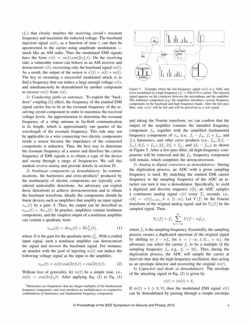
Figure 5. Example where the low-frequency signal m(t) is a 1kHz sinewave modulated on a high frequency (fc = 826MHz) carrier. The injectedsignal appears on the conductor between the microphone and the amplifier.The nonlinear component (e.g. the amplifier) introduces several frequencycomponents in the baseband and high frequency bands. After the low-passfilter, only m(t) will be left and will be perceived as a real signal.
and taking the Fourier transform, we can confirm that theoutput of the amplifier contains the intended frequencycomponent fm together with the amplified fundamentalfrequency components of vin (i.e., fc − fm, fc + fm, andfc), harmonics, and other cross products (i.e., fm, 2(fc −fm), 2(fc + fm), 2fc, 2fc + fm, and 2fc − fm), as shownin Figure 5. After a low-pass filter, all high-frequency com-ponents will be removed and the fm frequency componentwill remain, which completes the downconversion.
3) Analog to digital converters as demodulators: Duringthe digitization process, an ADC with a given samplingfrequency is used. By matching the emitted EMI carrierfrequency to the sampling frequency of the ADC an at-tacker can turn it into a demodulator. Specifically, to yielda digitized and discrete sequence v[k], an ADC samplesa continuous analog signal v(t) every Ts seconds, i.e.,v[k] = v(t)|t=kTs
, k ∈ [1..∞]. Let V (f) be the Fouriertransform of the original analog signal, and let Vs(f) be thesampled signal. Then,
Vs(f) = fs
∞∑n=−∞
V (f − nfs),
where fs is the sampling frequency. Essentially, the samplingprocess creates a duplicated spectrum of the original signalby shifting to f − nfs for n = [−∞..1, 0, .. + ∞]. Anadversary can select the carrier fc to be a multiple of thesampling frequency fs, e.g., fc = 9fs. Thus, during thedigitization process, the ADC will sample the carrier atintervals that skip the high-frequency oscillation, thus actingas an envelope detector and recovering the original m(t).
4) Capacitor and diode as demodulators: The envelopeof the attacking signal in Eq. (2) is given by
e(t) = |m(t) + 1|.
If m(t) + 1 > 0,∀t, then the modulated EMI signal v(t)can be demodulated by passing through a simple envelope
In Proceedings of the IEEE Symposium on Security and Privacy, 2013. 4

detector consisting of a diode and a capacitor, which alsohappen to be a basic building blocks in many circuits.In at least one of the devices we used (the MTS300CBboard for MicaZ motes) we discovered that there are severalcapacitor combinations on the path between the microphoneand the amplifier. While a diode was not present in thatparticular circuit, the amplifier forces the current to flow inone direction through the circuit, thus having the circuit itselfbehave as a diode and making that circuit a good candidatefor extracting the baseband signal m(t).
F. Distance bounds
An important factor is the relationship between the fea-sible attack distance and the strength of an injected electricsignal. In a receiving circuit with resistance Rr, in order toinduce an electric signal with V volts, the received power(denoted by Pr) of an EMI signal is
Pr = V 2
Rr. (3)
Assuming that modulated EMI signals typically operatein the MHz–GHz frequency band and that adversaries are atleast 0.5 meters away, we formulate the signal propagationas far-field communication. Although an accurate radiopropagation model should account for multipath, shadowing,and fading, we utilize the free space propagation model tounderstand the basics of feasible attack distances. Consideran attacker at a distance d from the victim’s circuit whotransmits at a power level of Pt. Then the received power,Pr, is calculated from the Friis transmission equation.
Pr = PtGtGr(λ
4πd )2, (4)
where Gt and Gr are the antenna gains of the transmittingand receiving antennas respectively, and λ is the wavelengthof the signal.
For example, consider an adversary who transmits at100 mW with a 10 dB antenna. Suppose that the victim’sdevice responds well to an 826 MHz carrier with a receivingcircuit of resistance 1.5 kΩ and an extremely low gain of0.01 dB since it was not designed to receive radio signals.To induce 10 mV on the victim’s sensing circuit during anattack, from eq. (4) and eq. (3) the distance between theattacker’s antenna and the victim’s system can be at most11.2 m; this makes the attack practical. Using an antennawith a higher gain of 20 dB and a signal source output of1 W could increase the attack distance to over 50 m.
III. BASEBAND ATTACK METHODS AND EXPERIMENTS
Safety-critical systems such as medical devices commonlyhave low-pass filters that attenuate high-frequency signalswhere the resonant frequency ranges reside. An attackercan still send low frequency signals within the passbandof the filters and compensate for the frequency mismatchwith higher-power signals (around 1 W or more) or reduceddistance.
Peak used in a replay loop for injected signal
Peaks&matching&injected&signal&
Fibrilla4on&signal&
Figure 6. Generated forged heart beat with recognizable peaks at 1.1 Hz(Top). Print-out of the electrocardiogram of the patient simulator configuredto exhibit ventricular fibrillation (Bottom). The induced signal is visible onlead 5 in the middle right. The ECG erroneously reported a 66 bpm pulse.
A. External ECG
An electrocardiogram (ECG) device is designed to moni-tor cardiac activity (around 1 mV) by taking voltage readingsat the skin surface. ECGs connect to patients with conductivepads and leads.
1) Experimental setup: To investigate the effects of EMIon the system, we plugged an ECG to a patient simulator(Bio-Tek Lionheart) configured to exhibit symptoms of ven-tricular fibrillation. We used an arbitrary function generator(AFG) connected with a simple whip monopole antenna toradiate low-power EMI signals. To compensate for the lowtransmission power and the inefficient radiator, we left twoof the leads disconnected and placed them within 5 cm ofthe radiating antenna. Finally, we read the ECG screens todetermine whether the EMI injection was successful.
2) Antenna and vulnerable frequency range: When send-ing high-frequency signals above 1 MHz, no signals wereobserved at the ECG, although an induced voltage of over10 mVp–p was measured at the leads. The results showedthat the pads and leads can serve as the entry point forEMI to alter the sensor readings, but the high frequencyattenuation would make modulated EMI attacks difficult.
3) Baseband EMI attacks: We transmitted a basebandsignal that emulated a cardiac rhythm (heart beats) at 66bpm,as shown in Figure 6 (Top). After a stabilization period of60–120 seconds, we observed that on the right side of theprintout sheet in Figure 6, the peaks of the injected basebandsignals are visible, indicating that our EMI signal affectedthe sensor readings.
B. Cardiac implantable electrical devices (CIEDs)
CIEDs are used to treat cardiac diseases with electricalstimulation. Under most configurations, pacemakers anddefibrillators will send low-energy electrical stimulations(around 10µJ) to pace the cardiac tissue if no cardiac activity
In Proceedings of the IEEE Symposium on Security and Privacy, 2013. 5

2.4 cm
1cm
Figure 7. Illustration of the connector and tip of typical active fixationcorkscrew bipolar pacemaker leads. The central cathode connector isextended further than the external anode and the cathode tip protrudesfurther than the anode ring.
is detected. Additionally defibrillators can be configuredto detect potentially dangerous rhythms such as fibrillationor tachycardia, and deliver a shock (around 25 J) [25] toreset all the electrical cardiac signals so that normal cardiacactivity may resume.
1) EMI coupling on leads: Leads threaded through bloodvessels and into the cardiac chambers connect a CIEDto the cardiac tissue. With the standard lead design, it ispossible to induce a voltage when exposed to EMI [20]. Dueto flexibility requirements, instead of true coaxial designs,leads use wound coaxial designs with the outside conductor(i.e. the anode) tightly wound around the central insulatedconductor (i.e. the cathode). On the lead end that connects tocardiac tissues, the central wire protrudes at what is calledthe cathode tip. That tip is about 2.4 cm longer than theexternal conductor that stops at what is called the anode ring(Figure 7). On the lead end that connects to the CIED, theanode is 1 cm longer than the cathode. This design combinedwith the difference in length between the anode and cathodeconductors allow a voltage to be induced by EMI. Whenradiating a 32 MHz signal at 300 mW from 14 m away, weobserved induced voltages of around 100 mV between theanode and the cathode of a bipolar lead. Signals under1 MHz induced lower voltages.
2) Vulnerable frequency range: CIEDs are designed toamplify specific regions such as the 0.1 Hz–1 kHz range [23]that contain electrogram information. To study their fre-quency response, we first disassembled an implantable pace-maker and measured the output of the first filter that isconnected to the lead. The measurements show that signalsbelow 5 MHz are only attenuated by 4dB, and signalsbeyond 200 MHz and 800 MHz are attenuated by 30 dBand 40 dB respectively, making high-frequency signals apoor choice for an attacker. To obtain the system wide fre-quency response, we ran a sweep in the low-frequency rangebetween 0.1 Hz and 1 kHz and observed the resulting relativesignal amplitude reported on the programmer connected tothe device. Signals in the 100 Hz–300 Hz range from ouramplifier showed the strongest amplitudes.
3) Baseband attack experimental setup: We performedthe experiments under different conditions including:
• Free air, providing conditions to find good candidatewaveforms for injected signals that would have a mea-surable impact on the system;
• Saline bath with a 1.8g/L NaCl concentration, builtfollowing the ANSI/AAMI PC69 specifications forelectromagnetic compatibility testing of cardiac de-vices [17]; and
• Synthetic human with a functioning circulatory system(using saline solution) and partial model of the humanheart [26]. Resistance measurements of the synthetichuman’s tissue showed that it is an approximate matchwith human tissue.
In our experiments we used 3 defibrillators (MedtronicInSync Sentry - 2005, Boston Scientific Cognis 100-D -unknown year, St. Jude Promote - 2007) and one pacemaker(Medtronic Adapta - 2006). For each CIED tested, weattached the same set of bipolar sensing and pacing leads(Pacetronix Model No. 3851 VB) in the Left Ventricle(“LV”) port. Preliminary results with a different set of leads(Guidant Dextrus 4137) showed comparable results. For theattacking waveform frequency in the 0.1 Hz to 1 kHz range,we used an audio amplifier connected to a wire used as asimple whip antenna. The amplifier’s estimated output was10 W, corresponding to 50 volts over a 250 Ω load at the out-put. The effective radiated power was much lower because ofthe mismatched antenna. Nevertheless, our radiating systemwas sufficient to produce noticeable induced signals.
Our goal was to create pacing inhibition (atrial or ven-tricular) and defibrillation shocks. To determine success, weused the electrogram readings displayed by a programmercompatible with the device under test. To inhibit pacing, weinjected a 100 Hz sinusoid signal, a pulsed sinusoid witha 100 ms width at 1 pulse per second, and a waveformfrom the ANSI/AAMI EC13 set amplitude-modulated over100 Hz. To induce fibrillation events, we used the waveformnumber 421 from the MIT-BIH Malignant Ventricular Ec-topy Database, an electrogram recording of a real episodeof ventricular fibrillation.
4) Results: The results are summarized in Table I. Pacinginhibition in free air can be accomplished from the furthestdistance (1.5 m), and pacing inhibition in saline solutionwere the most difficult condition to produce (5 cm or under).In free air, we did 20 trials for all devices except for the St.Jude device where only 8 trials were recorded. The synthetichuman measurements only had 2 trials.
Pacing inhibition. In the free air tests, the pulsed andmodulated sinusoid signals at 30 V p–p effectively stoppedpacing on all tested devices from 0.68 m to 1.57 m. A sampleoutput from the Medtronic programmer is shown in Figure 8(Top) showing a purple Ventricular Sense (VS) marker afterthe onset of our EMI signal.
Testing using saline solution, we used two setups. Wefirst arranged the leads in an arc and completely submergedthe device in the saline solution. We injected signals witha maximum amplitude of 50 V p–p, but we were unable tocause pacing inhibition with submerged devices, althoughour attenuated signal was observed on the EGM. In a second
In Proceedings of the IEEE Symposium on Security and Privacy, 2013. 6

Device Open air Open air (defibrillation) Saline bath Saline (lead tips only) SynDaver
Medtronic Adapta 1.40 m Not applicable No inhibition 0.03 m UntestedMedtronic InSync Sentry 1.57 m 1.67 m No inhibition 0.05 m 0.08 mBoston Scientific Cognis 100-D 1.34 m No defibrillation No inhibition Untested UntestedSt. Jude Promote 0.68 m No defibrillation No inhibition Untested Untested
Table IMEDIAN MAXIMUM DISTANCE AT WHICH A REPONSE (PACING INHIBITION UNLESS OTHERWISE SPECIFIED) FROM THE DEVICE WAS OBSERVED.
DEVICES WERE CONFIGURED IN BIPOLAR MODE. DIFFERENT WAVEFORMS WERE USED FOR THE PACING INHIBITION AND DEFIBRILLATION TESTS.
Onset of EMI signal
Ventricular Sense Markers
Sensed fibrilla-on
Onset of EMI signal
Defibrilla-on shock
Figure 8. Free air interference with the Medtronic InSync Sentryimplantable cardiac defibrillator. After the onset of the EMI signal, thedevice reported ventricular sense (Top) and fibrillation sense (Bottom). TheFD label indicates the point at which the defibrillation shock was delivered.
setup with only the bipolar leads tips in the solution and thedevice in free air, configured to sense in bipolar mode, wecan inhibit pacing at a range of 2 cm to 3 cm.
We also tested the the Medtronic InSync Sentry implantedin the synthetic human. For these tests, a cardiologist usedthe common approach by threading the leads through theaxillary vein under the left clavicle [27]. The tip of thelead was guided inside the model heart. With the salinesolution flowing through the model at approximately 60 bpm,we were able to inhibit pacing only using the modulatedsinusoid signal with an amplitude of 50 V p–p at a rangenot exceeding 8 cm from the leads.
Defibrillation shocks. For the fibrillation test, we usedthe Medtronic InSync Sentry in free air and saline, alongwith the 421 waveform as mentioned above. A snapshot ofthe response as displayed by the programmer is shown inFigure 8 (Bottom) with markers showing fibrillation sense(FS) events and a defibrillation (FD) event after the onsetof the EMI signal. With our 10 W amplifier, the medianmaximum range was 1.67 m in free air, and the results werenegative in saline solution. These results indicate that anattack is possible with the waveform we used, but a powersource greater than 10 W would be needed.
IV. MODULATED ATTACK METHODS AND EXPERIMENTS
Devices lacking low-pass filters are more sensitive toEMI because they do not attenuate signals outside of thebaseband, and thus can act as efficient receivers for high-frequency signals close to the circuit’s resonant frequency.This work focuses on microphones as example of unfiltereddevices; first outlining a reverse AM tuning method to locatethe resonant frequency and then demonstrating the injectionof: DTMF tones, music, speech, and audio test waveforms.We use the Speech Transmission Index [28] and the Shazamservice based on spectral fingerprinting [29] to evaluate thestrength and fidelity of injected signals.
A. Finding the resonant frequency
The conducting path between a microphone and theaccompanying amplification circuit can act as an antenna, asdiscussed in Section II. This creates a likely entry point forsignal injection. To launch a successful attack, an adversarymust find a frequency satisfying two conditions on the targetcircuit: (1) suitable for demodulation of the baseband signal,(2) close enough to the resonant frequency to induce a highvoltage. It is difficult to calculate the frequency responses ofthe conducting path and other circuit components, especiallyif no technical details are available. However, an attacker canmeasure the resonant frequency empirically, possibly withpartial information of the device, such as the length of theconducting path.
Based on the technical details available and analysisnecessary to develop an injected waveform, modulated EMIattacks fall into three categories: black box, gray box, andwhite box. We tested each class of attack using a signalgenerator that operates in the 9.00 kHz–2.02 GHz frequencyrange to modulate and transmit signals. The basebandwaveforms used include a simple 440 Hz sinusoid, and anarbitrary audio waveform called the “Weezer” waveformafter the band that produced the sample [30].
1) Black box with no technical details: We first useda webcam (Logitech Quickcam Ultravision) with a cameraand microphone integrated into a single enclosure. With nodirectly observable indication of the conducting path lengthbetween the microphone and the amplifier, we could notapproximate the resonant frequency. For all experiments, weconnected the webcam to a laptop to capture the audio output
In Proceedings of the IEEE Symposium on Security and Privacy, 2013. 7

700 750 800 850 900 950 1000 1050 11000
0.5
1
1.5
2 x 10⁻³
Transmit Carrier Frequency (MHz)
Pow
er S
pect
ral D
ensi
ty
Figure 9. Power spectral density of the recovered 440Hz tone modulatedon a range of carrier frequencies. The 820 MHz to 840 MHz range showeda high response, indicating that carriers within that band are likely tosuccessfully inject signals.
and fixed the signal generator’s output power at 80 mW. Forshort-range experiments, we used a whip antenna placedwithin 20 cm of the webcam. For longer-range experiments,we used a dipole antenna with higher gain to obtain the sameresults from ∼1 m away.
Results: Figure 9 shows the amplitude of the receivedsignal when modulating a single 440 Hz tone onto a rangeof carrier frequencies. This test revealed that the webcam’sresonant frequency was between 820 MHz and 840 MHz.We next attempted to inject an arbitrary waveform bymodulating the Weezer waveform onto a frequency in theresonant range. The commercial Shazam service, which usesa spectral fingerprinting method to identify audio samples,correctly identified the recovered waveform, indicating thatthe audio was clear enough to be recognized.
2) Gray box with limited technical details: We next foundthe resonant frequency of a Bluetooth headset (PlantronicsVoyager 510) based on partial information of the circuit.A disassembly revealed that the microphone–amplifier con-ducting path was approximately 6 cm, which correspondsto a resonant frequency of approximately 1.25 GHz if wemodel the conducting path as a whip antenna. Thus, insteadof the entire frequency range, we swept the carrier frequencyfrom 1.0 to 1.5 GHz to pinpoint the resonant frequency. Theoutput of the signal generator was fixed at 20 mW and wepositioned the transmitting antenna 10 cm from the headset.
Results: Using the single tone at 440 Hz, we found theresonant frequency of the headset at 1.175 GHz, whichmatches the predicted range. In this case, the length of theconducting path was useful in locating the resonant fre-quency. We then modulated the Weezer waveform onto theresonant frequency and the recovered signal was correctlyidentified by the Shazam service.
3) White box with available technical details: A MicaZmote fitted with an MTS300CB sensor board served asa white box attack target. The manufacturer’s schematicdocuments multiple capacitors in the path between the mi-crophone and the amplifier. These components are analogousto a simple envelope detector, as discussed in Section II-E,and are a likely entry point for injected EMI. To ensurethat the resonant frequency was within the limits of our
transmitting equipment, we modified the circuit by fitting15 cm wires between the microphone and the rest of theboard. We then measured the induced voltage on the leadsas we swept the EMI signals from 9.00 kHz to 2.02 GHzwith the output at 20 mW and the transmitting antenna lessthan 1 m from the the MicaZ mote. The mote digitized themeasured audio from the sensor board and forwarded thedata to a laptop via a second mote acting as a base station.
Results: By first measuring the voltage at the wires, wenoted a peak around 83 MHz and confirmed the suitabilityof this carrier frequency for signal injection by modulatinga single 440 Hz tone and recovering it at the applicationlayer. When we tested the Weezer waveform the recoveredwaveform was recognizable, but the Shazam service wasunable to retrieve the record, possibly due to the change inpitch and speed resulting from the mote’s primitive codec.We also noticed that an efficient whip antenna for 83 MHzshould be about 6 times longer than the wires we used. Thismismatch suggests that estimating the resonant frequencybased only on the length of the conducting path may not be areliable technique. The unknown impedance of the receivingcircuit may alter the expected resonant frequency sufficientlyto require a manual frequency sweep in some cases.
B. Dominating a legitimate signal
It is difficult to inject forged signals that can removelegitimate signals because cancellation requires a high-fidelity model for the waveforms arriving at the sensor.Instead, an attacker can inject a powerful forged signal todominate the legitimate signal. In systems with automaticgain control, powerful injected signals could force the gainto be automatically reduced to avoid circuit saturation. As aresult, the legitimate signal experiences fading.
There are two possible outcomes for an attacker attempt-ing to overwhelm a legitimate signal: (1) The legitimatesignal is low and the injected signal dominates, leadingto a successful attack; (2) The legitimate signal is highand the injected signal cannot completely dominate withoutsaturating the amplifier. In this case, the attack acts as asimple denial of service resulting in distorted audio.
To quantify the effectiveness of modulated EMI attacks,we use the Signal-to-Interference Ratio (SIR) defined as
SIR = 10× log10(PSignal
PInterference) (5)
where PSignal and PInterference are the power levels of themeasured signal and the induced forged signal respectively.The SIR quantifies how much stronger the legitimate signalis relative to the injected signal. A negative SIR indicatesthat the injected signal is stronger than the legitimate oneand the legitimate signal is difficult to recognize.
Results. We used an audio tone (440 Hz) as the legitimatesignal and a single tone (550 Hz) modulated over the reso-nant 826 MHz carrier as the EMI signal. Figure 10 shows the
In Proceedings of the IEEE Symposium on Security and Privacy, 2013. 8

0 10 20 30 40 50 60 70 80−20
−10
0
10
20
30
40
50
60
70
80
Output Power (mW)
Sign
al to
Inte
rfere
nce
Ratio
(dB)
Injected signal dominates in this region
Figure 10. Signal-to-Interference Ratio (SIR) as the transmission poweris increased with 50 Ω at the output. At an SIR below 0 dB, the injectedsignal dominates. The 3 sharp dips were caused by the transmitting signalgenerator switching between power modules.
SIR when varying the output power of the signal generator.As expected, the SIR has an inverse relationship with theoutput power of the signal generator. In the region wherethe SIR < 0, the interfering signal dominates.
C. Transmitting intelligible speech via EMI
To determine the feasibility of reliable intelligible speechtransmission over EMI, we used the Speech Transmission In-dex (STI) [28], a standard measure to predict speech intelli-gibility. The index is computed from the signal-to-noise ratio(SNR) at 8 octave bands covering the range from 125 Hz to8 kHz using the formula STI =
∑ni=1Wi[
SNRi+1530 ], where
n = 8 for most applications, Wi is a predefined weightassigned to each octave band, and SNRi is the receivedaudio SNR at the octave band i. The STI ranges from 0 to1, where 1 indicates a high likelihood of intelligible speechtransmission. We compared results between the injectedaudio over EMI and the legitimate acoustic channel.
Experimental setup. We chose three devices with micro-phones: the Bluetooth headset and webcam used earlier, inaddition to another webcam, a Logitech Quickcam VisionPro. For the audio, we used a standard STI test waveformconsisting of a uniform mixture of frequencies to allowan objective assessment of the response profiles. For theacoustic channel, the STI waveform was played through aMacBook Pro speaker system and recorded by the micro-phone of the device under test. For the EMI channel, wemodulated the STI waveform on the resonant frequencies ofeach device and transmitted the result over the air.
Results. We computed the average STI for the 3 devicesover audio with a mean of 0.69, and over EMI with a meanof 0.72, indicating that both channels are comparable forspeech transmission. Notice that the waveform transmittedvia the EMI channel has a slightly higher STI. The injectedsignal induces voltages on the conducting path between themicrophone and the amplifier and is therefore free of themechanical limits of the microphone itself. That effect isalso apparent in the lower octave bands in Figure 11.
D. Ghost talk use cases
We tested the modulated EMI attacks in a few real-worldscenarios: an automated telephone system, audio phone calls,and video teleconference calls. For all scenarios, we testedthree cases: a Bluetooth headset paired with a phone thatmade calls over cellular networks, a Bluetooth headset pairedwith a laptop that made calls over VoIP (using Skype orGoogle Chat), and a webcam connected to a laptop thatmade calls over VoIP.
Automated dial-in system. Many automated dial-in sys-tems take their customers’ inputs via telephone DTMF (DualTone Multiple Frequency) signals — sending keypad pressesas a unique combination of two audio tones. To demonstratereliable transmission of DTMF tones via EMI, we connectedto the dial-in service of Citibank’s credit card system. Wethen successfully entered the credit card number and zipcode sequences by injecting the corresponding DTMF tonesvia modulated EMI attacks, giving us access to the creditcard information. This result shows that it is possible touse EMI signals to initiate virtual button presses via DTMFduring a victim’s phone session with a remote system.
DoS attacks. To determine if we could overwhelm acous-tic signals to the point where none of the original signal wasapparent, we used the Weezer waveform and increased thepower as far as possible without causing distortion in thedemodulated audio. We then mounted an attack against aSkype session initiated with the Bluetooth headset. Shortlyafter the conversation started, we began transmitting the EMIsignal. The injected signals overwhelmed the acoustic signalto the point where the remote user could not detect the orig-inal acoustic signal. This result demonstrates that blockinga legitimate conversation is possible. For better results, asound-masking noise, such as a source of white noise witha uniform continuous spectrum could be used [31]. We hadsimilar results with a webcam connected to a laptop, as wellas transmission at higher power.
Session hijacking. Instead of completely blocking theacoustic signal, we also tried substituting the acoustic speechsignal with an EMI speech signal. This attack is similar inprinciple to injecting music, but the receiving user insteadhears speech that could plausibly replace the caller. Wetransmitted an EMI signal modulated with a reading ofEdgar Allan Poe: The Raven by James Earl Jones. Wetransmitted the signal immediately after the victim initiateda phone call using the Bluetooth headset. The injectedspeech introduced additive audio signals observable by thecalling party, but it did not completely mask the victim’svoice. To the receiving user, the acoustic signal appeared asbackground noise with the EMI signal coming across clearly.We suspect that it is possible to obscure the victim’s voiceas long as the EMI signal is powerful enough. In our case,we were limited by the signal generator with a maximumoutput power of 80 mW and a low-gain antenna.
In Proceedings of the IEEE Symposium on Security and Privacy, 2013. 9

200 500 1000 2000 5000
05
10
15
Frequency (Hz)
Ave
rag
e S
NR
(d
B)
Audio
EMI
Headset, audio on 1.15GHz EMI
200 500 1000 2000 5000
−1
0−
50
51
0
Frequency (Hz)
Ave
rag
e S
NR
(d
B)
Audio
EMI
Webcam1, audio on 629MHz EMI
200 500 1000 2000 5000
−1
0−
50
51
0
Frequency (Hz)
Ave
rag
e S
NR
(d
B)
Audio
EMI
Webcam2, audio on 829MHz EMI
Figure 11. Frequency responses of acoustic input and EMI signal for the devices tested using the Speech Transmission Index waveform. The high SNRover EMI at low frequencies indicates a better response than the audio signal, possibly due to bypassing mechanical constraints in the microphone.
Analog Defenses
Analog Signal Amp + ADC
Sensing Output +
EMIMonitorEMI Emitter
Signal + Contamination
Adaptive Filter Σ
ContaminationChecker
ref
Safe Default
Normal Logic
Contamination Level Induced
Waveform
Actuator
Analog Digital
Figure 12. Overview of the defenses, integrated in a single system. The signal first goes through a number of analog defenses to attenuate the induced signalbefore conversion into a digital format. A subsystem simultaneously takes readings of the EMI level in the environment to determine the contaminationlevel. Further filtering is then possible based on the estimated EMI level. Active probing can also be used to help discriminate between induced andmeasured signals. Finally, if the probing results indicate a forged waveform capable of forcing improper actuation, we revert to a safe default.
V. DEFENSES
The goal of our defense set is to improve the trustwor-thiness of the sensor readings by attenuating the inducedsignals or at minimum detect EMI attacks. We propose asystem (Figure 12) composed of a series of analog anddigital defenses that can attenuate the EMI on the analogsensor circuit, differentiate between induced and measuredsignals in the digital circuit, remove the induced signalsif possible, and revert to known safe defaults if the inter-fering signal is too strong. Although the analog defensesare known and some are already applied to implantablemedical devices, consumer electronics are less protected. Asthe cost of deploying those defenses is device-specific, weinstead quantified the attenuation which can be used for thecost/benefit analysis. The analog defenses on their own maynot be enough against strong emitters or baseband emitters.Thus in addition, we propose to use some digital defenses:adaptive finite impulse response filters that can improve theSIR, a probing-based method that can distinguish betweeninduced and measured signals, and a safe default mode fordevices in the presence of strong EMI attackers.
A. Analog defenses
In the analog portion of the sensing circuit, there arethree common defenses: shielding, differential comparators,and filters. All of these are used to some extent in modernCIEDs, but not in commodity electronics. In this section weapply those techniques and measure the resulting attenuationwith waveforms used in our modulated attacks. Those resultscan then be used for cost/benefit analysis to improve thedesign of current systems.
1) Shielding: The application of a conducting materialto shield a component from electromagnetic radiation iswell-known but absent from most commodity devices wetested. We coated the exterior of one of our webcamswith a conducting surface leaving large holes for a numberof components. Those include the camera lens, two largebuttons on the side, the microphone and the mechanicalstand. Even with large imperfections in the shield, theattenuation of the recovered EMI signal was over 40 dB,forcing an attacker to transmit 104 times more power tohave the same effect.
In Proceedings of the IEEE Symposium on Security and Privacy, 2013. 10

2) Differential comparator: Where shielding is either notpossible or not sufficient, a reference signal can be usedto remove the common mode voltage using a differentialcircuit, commonly used in analog electronics [32]. By mea-suring the difference in potential between two voltages,the common mode interference present on both signals iseffectively filtered out.
Early designs of pacemakers used unipolar leads (one sin-gle conductor in lead connected to the cardiac tissue), whichwas eventually phased out in favor of the “true bipolar”design [27]. Under similar conditions with a signal injectionwaveform (see Section III) we measured the attenuation ofthe induced signal from a bipolar lead to be 30 dB, showinga significant reduction in EMI induced signal with a simpledefense.
Even with a bipolar design, our results indicate a possibil-ity to induce a differential mode signal across the anode andthe cathode of the leads. In free air, with a 100 Hz sinusoidon an 80 mW source at 20 cm, we measured that the inducedvoltage difference is on the order of 5 mV and the phase shiftis on the order of π/10. The differential voltage and phasedifference became very small with the tips dipped in thesaline solution, leading to a severe drop in the differentialvoltage. We had to significantly increase the transmit powerof our emitter to return the measured differential voltages toaround 5 mV even when dipped in saline solution, indicatingthat the attacker can compensate with increased power.
3) Filters: A filter that attenuates signals outside a sen-sor’s baseband frequency can reduce the vulnerable fre-quency range of that sensor. Such filters are already in usein medical devices, but they seem more sparse in com-modity electronics. Those are therefore more vulnerable tosignal injection attacks with a high frequency carrier, bettermatched to the vulnerable circuit. To test the effectivenessof filters for commodity electronics, we used a custom-builtactive low-pass filter at 500MHz to attenuate high-frequencycomponents while allowing audio signals (below 50 kHz) topass. In the case of the 836 MHz carrier from the attackwaveform we suggested in Section IV, an attenuation ofover 40dB was measured, making it a very good attenuatoragainst our signal.
B. Digital Defenses
Due to physical requirements or packaging limitations ofimplantable medical devices, some of the analog defensesoutlined above may have a limited effect, especially againsta strong emitter. As a result, the output of the sensor may stillcontain injected signals. In addition to the analog attenuationdefenses, we propose techniques on the digitized signal toestimate, track, clean, and verify the state of the signal as itmoves through the system.
1) Signal contamination: A necessary component of oursignal injection attack is an EM wave to carry the signal. Ifa component in the victim’s device is available to capture
only the radiated signal, we can estimate the EMI levelin the environment. We call this estimation the signalcontamination. Components downstream can then use thecontamination level to determine the appropriate defensesto apply.
As a metric of the required conditions for EMI attacks,we use the root mean square of the waveform amplitudein a window of size wms to estimate the EMI level in theenvironment. To compute the contamination level, lc, wecompare the measured level (At) to one calibrated in a quietenvironment(A0).
lc = RMS(At)RMS(A0)
, (6)
where t is the start time for a window of size w underconsideration, and RMS is the root mean square of thewaveform amplitude as defined by
RMS(AT ) =√
1w
∫ T+w
TA2t , (7)
where T < t < T + w.In communicating implantable medical devices, the RF
antenna can be used to estimate the ambient EMI. In non-communicating devices that lack an antenna, a referenceconductor can be used instead. We assume that the monitor-ing component is located close enough to the vulnerable partof the sensor to receive comparable levels of EMI radiation.In the presence of a pulsed EMI signal with increasingpower, similar to the pulse from Section III, the commu-nication antenna on our disassembled CIED recovered thesignal shown in the spectrogram in Figure 13 (Top). The300 Hz pulses with increasing power are clearly visible.The bottom graph shows the computed contamination levelwith a window of size w = 100 ms based on the observedwaveforms. In our free air experiments, a pacing inhibitionwould occur for devices exposed to contamination levels of2.1 and higher.
Figure 13. Top: Increasing strength of attacker signal. Bottom: Computedcontamination level.
In Proceedings of the IEEE Symposium on Security and Privacy, 2013. 11
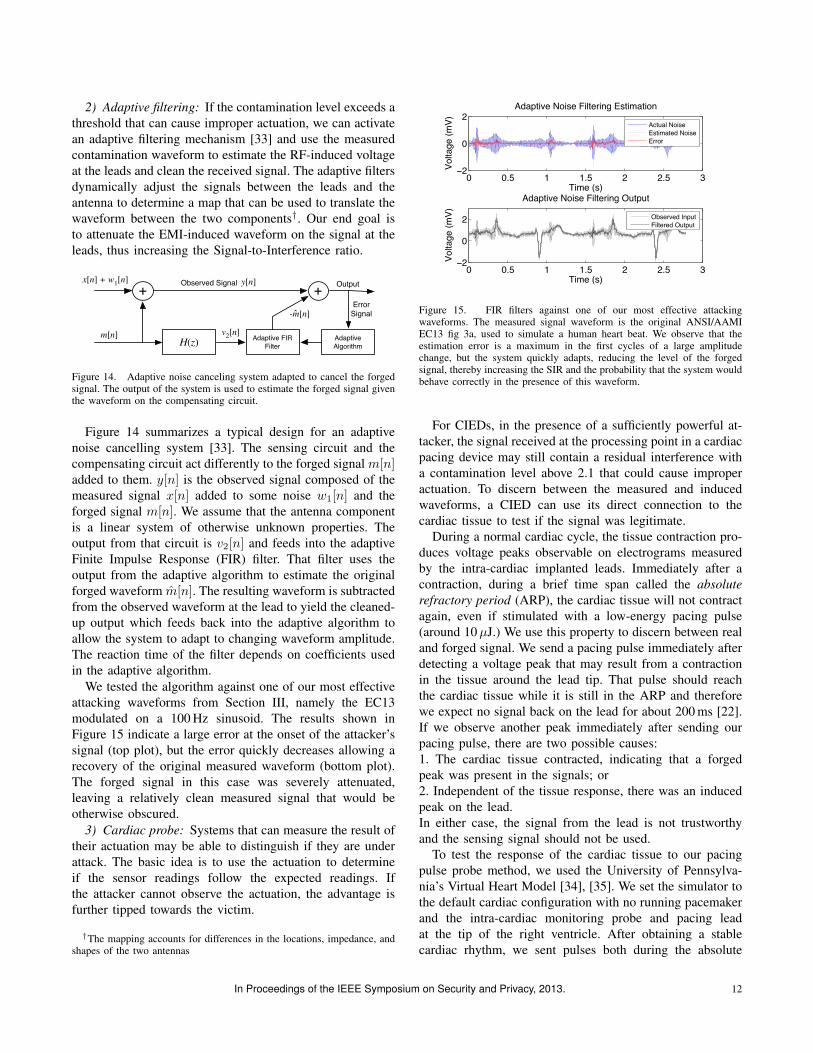
2) Adaptive filtering: If the contamination level exceeds athreshold that can cause improper actuation, we can activatean adaptive filtering mechanism [33] and use the measuredcontamination waveform to estimate the RF-induced voltageat the leads and clean the received signal. The adaptive filtersdynamically adjust the signals between the leads and theantenna to determine a map that can be used to translate thewaveform between the two components†. Our end goal isto attenuate the EMI-induced waveform on the signal at theleads, thus increasing the Signal-to-Interference ratio.
+
H(z) Adaptive FIR Filter
+
Adaptive Algorithm
ErrorSignal
OutputObserved Signalx[n] + w1[n] y[n]
m[n] v2[n]
-m[n]ˆ
Figure 14. Adaptive noise canceling system adapted to cancel the forgedsignal. The output of the system is used to estimate the forged signal giventhe waveform on the compensating circuit.
Figure 14 summarizes a typical design for an adaptivenoise cancelling system [33]. The sensing circuit and thecompensating circuit act differently to the forged signal m[n]added to them. y[n] is the observed signal composed of themeasured signal x[n] added to some noise w1[n] and theforged signal m[n]. We assume that the antenna componentis a linear system of otherwise unknown properties. Theoutput from that circuit is v2[n] and feeds into the adaptiveFinite Impulse Response (FIR) filter. That filter uses theoutput from the adaptive algorithm to estimate the originalforged waveform m[n]. The resulting waveform is subtractedfrom the observed waveform at the lead to yield the cleaned-up output which feeds back into the adaptive algorithm toallow the system to adapt to changing waveform amplitude.The reaction time of the filter depends on coefficients usedin the adaptive algorithm.
We tested the algorithm against one of our most effectiveattacking waveforms from Section III, namely the EC13modulated on a 100 Hz sinusoid. The results shown inFigure 15 indicate a large error at the onset of the attacker’ssignal (top plot), but the error quickly decreases allowing arecovery of the original measured waveform (bottom plot).The forged signal in this case was severely attenuated,leaving a relatively clean measured signal that would beotherwise obscured.
3) Cardiac probe: Systems that can measure the result oftheir actuation may be able to distinguish if they are underattack. The basic idea is to use the actuation to determineif the sensor readings follow the expected readings. Ifthe attacker cannot observe the actuation, the advantage isfurther tipped towards the victim.
†The mapping accounts for differences in the locations, impedance, andshapes of the two antennas
0 0.5 1 1.5 2 2.5 3−2
0
2Adaptive Noise Filtering Estimation
Time (s)
Volta
ge (m
V)
Actual NoiseEstimated NoiseError
0 0.5 1 1.5 2 2.5 3−2
0
2
Adaptive Noise Filtering Output
Time (s)
Volta
ge (m
V)
Observed InputFiltered Output
Figure 15. FIR filters against one of our most effective attackingwaveforms. The measured signal waveform is the original ANSI/AAMIEC13 fig 3a, used to simulate a human heart beat. We observe that theestimation error is a maximum in the first cycles of a large amplitudechange, but the system quickly adapts, reducing the level of the forgedsignal, thereby increasing the SIR and the probability that the system wouldbehave correctly in the presence of this waveform.
For CIEDs, in the presence of a sufficiently powerful at-tacker, the signal received at the processing point in a cardiacpacing device may still contain a residual interference witha contamination level above 2.1 that could cause improperactuation. To discern between the measured and inducedwaveforms, a CIED can use its direct connection to thecardiac tissue to test if the signal was legitimate.
During a normal cardiac cycle, the tissue contraction pro-duces voltage peaks observable on electrograms measuredby the intra-cardiac implanted leads. Immediately after acontraction, during a brief time span called the absoluterefractory period (ARP), the cardiac tissue will not contractagain, even if stimulated with a low-energy pacing pulse(around 10µJ.) We use this property to discern between realand forged signal. We send a pacing pulse immediately afterdetecting a voltage peak that may result from a contractionin the tissue around the lead tip. That pulse should reachthe cardiac tissue while it is still in the ARP and thereforewe expect no signal back on the lead for about 200 ms [22].If we observe another peak immediately after sending ourpacing pulse, there are two possible causes:1. The cardiac tissue contracted, indicating that a forgedpeak was present in the signals; or2. Independent of the tissue response, there was an inducedpeak on the lead.In either case, the signal from the lead is not trustworthyand the sensing signal should not be used.
To test the response of the cardiac tissue to our pacingpulse probe method, we used the University of Pennsylva-nia’s Virtual Heart Model [34], [35]. We set the simulator tothe default cardiac configuration with no running pacemakerand the intra-cardiac monitoring probe and pacing leadat the tip of the right ventricle. After obtaining a stablecardiac rhythm, we sent pulses both during the absolute
In Proceedings of the IEEE Symposium on Security and Privacy, 2013. 12
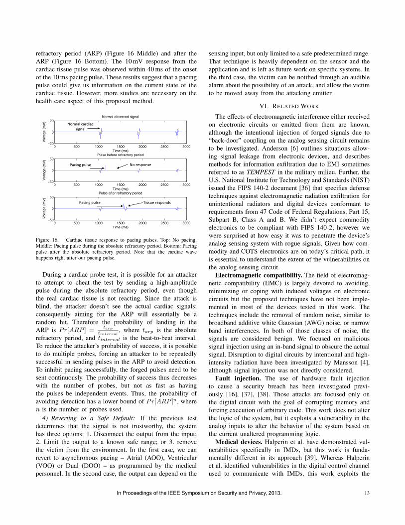
refractory period (ARP) (Figure 16 Middle) and after theARP (Figure 16 Bottom). The 10 mV response from thecardiac tissue pulse was observed within 40 ms of the onsetof the 10 ms pacing pulse. These results suggest that a pacingpulse could give us information on the current state of thecardiac tissue. However, more studies are necessary on thehealth care aspect of this proposed method.
0 500 1000 1500 2000 2500 3000−20
0
20
Time (ms)
Volta
ge (m
V)
Normal observed signal
0 500 1000 1500 2000 2500 3000−50
0
50
Time (ms)
Volta
ge (m
V)
Pulse before refractory period
0 500 1000 1500 2000 2500 3000−50
0
50
Time (ms)
Volta
ge (m
V)
Pulse after refractory period
Normal'cardiac'signal'
Pacing'pulse'
Pacing'pulse'
No'response'
Tissue'responds'
Figure 16. Cardiac tissue response to pacing pulses. Top: No pacing.Middle: Pacing pulse during the absolute refractory period. Bottom: Pacingpulse after the absolute refractory period. Note that the cardiac wavehappens right after our pacing pulse.
During a cardiac probe test, it is possible for an attackerto attempt to cheat the test by sending a high-amplitudepulse during the absolute refractory period, even thoughthe real cardiac tissue is not reacting. Since the attack isblind, the attacker doesn’t see the actual cardiac signals;consequently aiming for the ARP will essentially be arandom hit. Therefore the probability of landing in theARP is Pr[ARP ] =
tarp
tinterval, where tarp is the absolute
refractory period, and tinterval is the beat-to-beat interval.To reduce the attacker’s probability of success, it is possibleto do multiple probes, forcing an attacker to be repeatedlysuccessful in sending pulses in the ARP to avoid detection.To inhibit pacing successfully, the forged pulses need to besent continuously. The probability of success thus decreaseswith the number of probes, but not as fast as havingthe pulses be independent events. Thus, the probability ofavoiding detection has a lower bound of Pr[ARP ]n, wheren is the number of probes used.
4) Reverting to a Safe Default: If the previous testdetermines that the signal is not trustworthy, the systemhas three options: 1. Disconnect the output from the input;2. Limit the output to a known safe range; or 3. removethe victim from the environment. In the first case, we canrevert to asynchronous pacing – Atrial (AOO), Ventricular(VOO) or Dual (DOO) – as programmed by the medicalpersonnel. In the second case, the output can depend on the
sensing input, but only limited to a safe predetermined range.That technique is heavily dependent on the sensor and theapplication and is left as future work on specific systems. Inthe third case, the victim can be notified through an audiblealarm about the possibility of an attack, and allow the victimto be moved away from the attacking emitter.
VI. RELATED WORK
The effects of electromagnetic interference either receivedon electronic circuits or emitted from them are known,although the intentional injection of forged signals due to“back-door” coupling on the analog sensing circuit remainsto be investigated. Anderson [6] outlines situations allow-ing signal leakage from electronic devices, and describesmethods for information exfiltration due to EMI sometimesreferred to as TEMPEST in the military milieu. Further, theU.S. National Institute for Technology and Standards (NIST)issued the FIPS 140-2 document [36] that specifies defensetechniques against electromagnetic radiation exfiltration forunintentional radiators and digital devices conformant torequirements from 47 Code of Federal Regulations, Part 15,Subpart B, Class A and B. We didn’t expect commodityelectronics to be compliant with FIPS 140-2; however wewere surprised at how easy it was to penetrate the device’sanalog sensing system with rogue signals. Given how com-modity and COTS electronics are on today’s critical path, itis essential to understand the extent of the vulnerabilities onthe analog sensing circuit.
Electromagnetic compatibility. The field of electromag-netic compatibility (EMC) is largely devoted to avoiding,minimizing or coping with induced voltages on electroniccircuits but the proposed techniques have not been imple-mented in most of the devices tested in this work. Thetechniques include the removal of random noise, similar tobroadband additive white Gaussian (AWG) noise, or narrowband interferences. In both of those classes of noise, thesignals are considered benign. We focused on malicioussignal injection using an in-band signal to obscure the actualsignal. Disruption to digital circuits by intentional and high-intensity radiation have been investigated by Mansson [4],although signal injection was not directly considered.
Fault injection. The use of hardware fault injectionto cause a security breach has been investigated previ-ously [16], [37], [38]. Those attacks are focused only onthe digital circuit with the goal of corrupting memory andforcing execution of arbitrary code. This work does not alterthe logic of the system, but it exploits a vulnerability in theanalog inputs to alter the behavior of the system based onthe current unaltered programming logic.
Medical devices. Halperin et al. have demonstrated vul-nerabilities specifically in IMDs, but this work is funda-mentally different in its approach [39]. Whereas Halperinet al. identified vulnerabilities in the digital control channelused to communicate with IMDs, this work exploits the
In Proceedings of the IEEE Symposium on Security and Privacy, 2013. 13
analog sensing apparatus of pacemakers and defibrillators.This work also adopts an attack approach that is widelyapplicable to electronics with analog sensing inputs, notconstrained to any particular protocol or specific sensor.
CIEDs have been reported to be affected by static mag-netic fields [40] but only at very short distances of under3 cm, and Low Frequency RFID emissions [24] but thewaveforms were not intentionally crafted to force a mis-sense on the device.
In their work on bounding the distance between the com-munication device and an implantable medical device [41],Rassmussen et al. noted that the receiving microphone wassensitive to electromagnetic interference. Our work goesdeeper in analyzing signal injection using RF waveforms.We offer an analysis of the root causes of the vulnerabilityand develop an attack model using signal injection. Weevaluated our attacks on a number of devices includingcommodity electronics and implantable medical devices.
VII. CONCLUSION
Analog sensors intrinsically trust what they measure, anddigital systems trust the input provided by sensors. Asa result, intentional electromagnetic interference can tricksensors into providing bogus information to higher-levelapplications. Implications range from causing pacemakers tostop pacing to injecting chosen touch-tone numbers duringphone calls with a Bluetooth headset to an automatedbank service center. For distances under 5 cm for an 10 Wadversary, our experiments found no clinically relevant risksfor completely implanted medical devices. In free air, ourexperiments caused measurable interference at 1-2 m. Wedo not believe the current situation reveals an urgent publichealth risk. Our proposed defenses include traditional analogshielding as well as a digital signal contamination metricbased on the root mean square of waveform amplitudes. Ourcardiac defense mechanism detects suspicious sensor inputby checking whether pacing pulses are consistent with therefractory period of cardiac tissue. Secure websites followthe principle of not trusting unvalidated user input, and theanalog of this advice should resonate for sensor systems too.
ACKNOWLEDGMENT
This publication was made possible by CooperativeAgreement No. 90TR0003/01 from the Department ofHealth and Human Services. Its contents are solely theresponsibility of the authors and do not necessarily rep-resent the official views of the HHS. This work was alsosupported by a Sloan Research Fellowship; the Universityof Minnesota Doctoral Dissertation fellowship; the Koreangovernment (MEST) National Research Foundation (NRF)No. 2012-0000979; the Harvard Catalyst/Harvard Clinicaland Translational Science Center MeRIT career developmentaward and the National Science Foundation awards CNS-1035715, CNS-0845671, CNS-0923313, GEO-1124657, and
S121000000211. Any opinions, findings, and conclusions orrecommendations expressed in this material are those of theauthor(s) and do not necessarily reflect the views of theNational Science Foundation. Many thanks to Amir Rahmatifor creating figures and editing; Quinn Stewart for copyediting, Tingyi Wei for running experiments, the members ofthe SPQR Lab, Penn’s PRECISE center, the UMN MedicalDevice Center, and the UMN SCLab for feedback on drafts.
REFERENCES
[1] D. Giri and F. Tesche, “Classification of intentional elec-tromagnetic environments (IEME),” IEEE Transactions onElectromagnetic Compatibility, vol. 46, no. 3, pp. 322–328,2004.
[2] C. R. Paul, Electromagnetic Compatibility. Wiley OnlineLibrary, 2005.
[3] ——, “Introduction to electromagnetic compatibility (WileySeries in Microwave and Optical Engineering),” 2006.
[4] D. Mansson, R. Thottappillil, and M. Backstrom, “Methodol-ogy for classifying facilities with respect to intentional EMI,”IEEE Transactions on Electromagnetic Compatibility, vol. 51,no. 1, 2009.
[5] J.-M. Redoute and M. Steyaert, EMC of analog integratedcircuits. Springer, 2009.
[6] R. Anderson, Security Engineering: A guide to buildingdependable distributed systems. Wiley, 2010.
[7] A. Cheng, S. Nazarian, D. D. Spragg, K. Bilchick, H. Tan-dri, L. Mark, H. Halperin, H. Calkins, R. D. Berger, andC. A. Henrikson, “Effects of surgical and endoscopic electro-cautery on modern-day permanent pacemaker and implantablecardioverter-defibrillator systems,” Pacing and clinical elec-trophysiology, vol. 31, no. 3, pp. 344–350, 2008.
[8] J. Loewy, A. Loewy, and E. J. Kendall, “Reconsideration ofpacemakers and MR imaging,” Radiographics, vol. 24, no. 5,pp. 1257–1267, 2004.
[9] A. Roguin, J. Schwitter, C. Vahlhaus, M. Lombardi, J. Bru-gada, P. Vardas, A. Auricchio, S. Priori, and T. Sommer,“Magnetic resonance imaging in individuals with cardio-vascular implantable electronic devices,” Europace, vol. 10,no. 3, pp. 336–346, 2008.
[10] D. Hayes, P. Wang, D. Reynolds, N. Estes, J. Griffith, R. Stef-fens, G. Carlo, G. Findlay, and C. Johnson, “Interference withcardiac pacemakers by cellular telephones,” New EnglandJournal of Medicine, vol. 336, no. 21, 1997.
[11] K. Hekmat, B. Salemink, G. Lauterbach, R. Schwinger,M. Sudkamp, H. Weber, and U. Mehlhorn, “Interference bycellular phones with permanent implanted pacemakers: anupdate,” Europace, vol. 6, no. 4, pp. 363–369, 2004.
[12] G. Calcagnini, F. Censi, M. Floris, C. Pignalberi, R. Ricci,G. Biancalana, P. Bartolini, and M. Santini, “Evaluation ofelectromagnetic interference of GSM mobile phones withpacemakers featuring remote monitoring functions,” Pacingand clinical electrophysiology, vol. 29, no. 4, 2006.
In Proceedings of the IEEE Symposium on Security and Privacy, 2013. 14

[13] W. A. Radasky, C. E. Baum, and M. W. Wik, “Introductionto the special issue on high-power electromagnetics (HPEM)and intentional electromagnetic interference (IEMI),” IEEETransactions on Electromagnetic Compatibility, vol. 46, no. 3,pp. 314–321, 2004.
[14] M. G. Backstrom and K. G. Lovstrand, “Susceptibility ofelectronic systems to high-power microwaves: Summary oftest experience,” IEEE Transactions on Electromagnetic Com-patibility, vol. 46, no. 3, pp. 396–403, 2004.
[15] J. Delsing, J. Ekman, J. Johansson, S. Sundberg, M. Back-strom, and T. Nilsson, “Susceptibility of sensor networksto intentional electromagnetic interference,” in 17th Interna-tional Zurich Symposium on Electromagnetic Compatibility.IEEE, 2006, pp. 172–175.
[16] S. Govindavajhala and A. Appel, “Using memory errorsto attack a virtual machine,” in Proceedings of the IEEESymposium on Security and Privacy, 2003.
[17] American National Standards Institute/Association for theAdvancement of Medical Instrumentation (ANSI/AAMI),“Active implantable medical devices — Electromagnetic com-patibility — EMC test protocols for implantable cardiacpacemakers and implantable cardioverter defibrillators,” 2007.
[18] W. Irnich, L. Batz, R. Muller, and R. Tobisch, “Electromag-netic interference of pacemakers by mobile phones,” Pacingand clinical electrophysiology, vol. 19, no. 10, 1996.
[19] F. Censi, G. Calcagnini, M. Triventi, E. Mattei, and P. Bar-tolini, “Interference between mobile phones and pacemakers:a look inside,” Ann IST Super Sanita, vol. 43, no. 3, 2007.
[20] W. Kainz, J. Casamento, P. Ruggera, D. Chan, and D. Witters,“Implantable cardiac pacemaker electromagnetic compati-bility testing in a novel security system simulator,” IEEETransactions on Biomedical Engineering, vol. 52, no. 3, 2005.
[21] H. Moses and J. Mullin, A practical guide to cardiac pacing.Lippincott Williams & Wilkins, 2007.
[22] M. Kroll and M. Lehmann, Implantable CardioverterDefibrillator Therapy: The Engineering-Clinical Interface.Springer, 1996, vol. 188.
[23] L. Cohan, F. Kusumoto, and N. Goldschlager, “Environmentaleffects on cardiac pacing systems,” Cardiac Pacing for theClinician, 2008.
[24] S. J. Seidman, R. Brockman, B. M. Lewis, J. Guag, M. J.Shein, W. J. Clement, J. Kippola, D. Digby, C. Barber,and D. Huntwork, “In vitro tests reveal sample radiofre-quency identification readers inducing clinically significantelectromagnetic interference to implantable pacemakers andimplantable cardioverter-defibrillators,” Heart Rhythm, vol. 7,no. 1, p. 99, 2010.
[25] C. Sticherling, T. Klingenheben, D. Cameron, and S. H.Hohnloser, “Worldwide clinical experience with a down-sized active can implantable cardioverier defibrillator in 162consecutive patients,” Pacing and clinical electrophysiology,vol. 21, no. 9, pp. 1778–1783, 2006.
[26] Syndaver Labs, “Torso #02,” http://syndaver.com/productinfo.php?cPath=80&products id=493, Visited Nov 2012.
[27] D. Hayes, M. Lloyd, and P. Friedman, Cardiac pacing anddefibrillation: a clinical approach. Wiley-Blackwell, 2000.
[28] International Electrotechnical Commission, “IEC 60268-16:Sound system equipment-part 16: Objective rating of speechintelligibility by speech transmission index,” 2003.
[29] A. Wang et al., “An industrial strength audio search algo-rithm,” in Proc. Int. Conf. on Music Info. Retrieval ISMIR,vol. 3, 2003.
[30] Weezer, “Island in the sun,” Weezer (The Green Album),Geffen Records, Compact Disc, 2001.
[31] G. A. Miller, “The masking of speech.” Psychological Bul-letin, vol. 44, no. 2, p. 105, 1947.
[32] Razavi and Behzad, Design of Analog CMOS IntegratedCircuits, 1st ed. McGraw-Hill, Inc., 2001.
[33] J. G. Proakis and D. G. Manolakis, Digital Signal Processing:Principles, Algorithms, and Applications, 4th ed. PearsonPrentice Hall, 2007.
[34] Z. Jiang, M. Pajic, A. Connolly, S. Dixit, and R. Mangharam,“Real-time heart model for implantable cardiac device vali-dation and verification,” in 22nd Euromicro Conference onReal-Time Systems (ECRTS), 2010.
[35] Z. Jiang and R. Mangharam, “Modeling cardiac pacemakermalfunctions with the virtual heart model,” in Annual Inter-national Conference on Engineering in Medicine and BiologySociety, EMBC, 2011.
[36] National Institute of Standards and Technology, “140-2: Se-curity requirements for cryptographic modules,” 2001.
[37] J. Karlsson, P. Folkesson, J. Arlat, Y. Crouzet, G. Leber, andJ. Reisinger, “Application of three physical fault injectiontechniques to the experimental assessment of the MARSarchitecture,” Dependable Computing and Fault Tolerant Sys-tems, vol. 10, 1998.
[38] E. Jenn, J. Arlat, M. Rimen, J. Ohlsson, and J. Karlsson,“Fault injection into VHDL models: the MEFISTO tool,”in Twenty-Fourth International Symposium on Fault-TolerantComputing (FTCS-24), 1994.
[39] D. Halperin, T. Heydt-Benjamin, B. Ransford, S. Clark,B. Defend, W. Morgan, K. Fu, T. Kohno, and W. Maisel,“Pacemakers and implantable cardiac defibrillators: Softwareradio attacks and zero-power defenses,” in IEEE Symposiumon Security and Privacy, 2008.
[40] S. Lee, K. Fu, T. Kohno, B. Ransford, and W. Maisel,“Clinically significant magnetic interference of implanted car-diac devices by portable headphones,” Heart Rhythm, vol. 6,no. 10, 2009.
[41] K. Rasmussen, C. Castelluccia, T. Heydt-Benjamin, andS. Capkun, “Proximity-based access control for implantablemedical devices,” in Proceedings of the 16th ACM conferenceon Computer and communications security, 2009.
In Proceedings of the IEEE Symposium on Security and Privacy, 2013. 15