Mitel Smart-1 Dialer Manuals
458
ISSUE 1. JUNE 1988 SECTION 8350-345012-NA SMART-l SMART-l CALL CONTROLLER MANUAL1 HARDWARE INSTALLATION @ Copyright 1988 MITEL INC. All rights reserved. @ Registered Trademark of MITEL Corporation PRINTED IN CANADA
-
Upload
dagskarlsen -
Category
Documents
-
view
137 -
download
12
description
Manuals Smart-1 dialers from Mitel
Transcript of Mitel Smart-1 Dialer Manuals

ISSUE 1. JUNE 1988 SECTION 8350-345012-NA
SMART-l
SMART-l CALL CONTROLLER
MANUAL1
HARDWARE INSTALLATION
@ Copyright 1988 MITEL INC. All rights reserved. @ Registered Trademark of MITEL Corporation
PRINTED IN CANADA
SECTION 8350-345012-NA
MITEL FIELD SERVICE
ISSUE 1, JUNE 1988
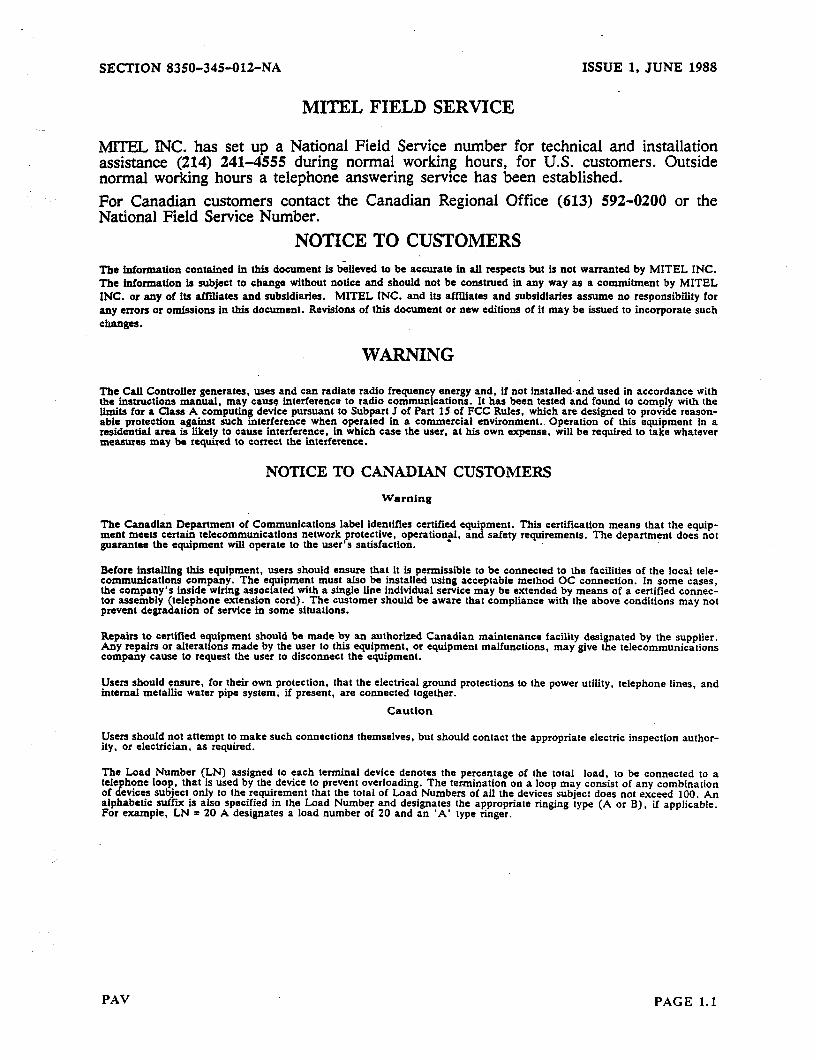
MLTEL INC. has set up a National Field Service number for technical and installation assistance (214) 241-4555 during normal working hours, for U.S. customers. Outside normal working hours a telephone answering service has been established. For Canadian customers contact the Canadian Regional Office (613) 592-0200 or the National Field Service Number.
NOTICE TO CUSTOMERS The information contained in this document is bheved to be accurate in all respects but is not warranted by MITEL INC. The htformation is subject to change without notice and should not be construed in any way as a commitment by MITEL INC. or any of its affiliates and subsidiaries. MITEL INC. and its affihates and subsidiaries assume no responstbility for any errors or omissions in this document. Revisions of this document or new editions of it may be issued to incorporate such changes.
WARNING
The Call Controller generates, uses and can radiate radio frequency energy and, if not installed.and used in accordance with the instructions manual. may cause interference to radio communications. It has been tested and found to comply with the limits for a Class A computing device pursuant to Subpart J of Part IS of FCC Rules, which are designed to provide reason- able protection against such interference when operated in a commercial environment. Operation of this equipment in a residential area is likely to cause interference, in which case the user, at his own expense, will be required to take whatever measures may be required to correct the interference.
NOTICE TO CANADIAN CUSTOMERS
Warning
The Canadian Department of Communications label identifies certified equipment. This certification means that the equip- ment meets certain telecommunications network protective, operation$. and safety requirements. The department does not guarantee the equipment will operate to the user’s satisfaction.
Before installing this equipment, users should ensure that it is permissible to be connected to the facilities of the local tele- communications company. The equipment must also be installed using acceptable method OC connection. In some cases, the company’s inside wiring associated with a single line individual service may be extended by means of a certified connec- tor assembly (telephone extension cord). The customer should be aware that compliance with the above conditions may not prevent degradation of service in some situations.
Repairs to certified equipment should be made by an authorized Canadian maintenance facility designated by the supplier. Any repairs or alterations made by the user to this equipment, or equipment malfunctions, may give the telecommunications company cause to request the user to disconnect the equipment.
Users should ensure, for their own protection, that the electrical ground protections to the power utility, telephone lines, and internal metallic water pipe system; if present, are connected together.
Caution
Users should not attempt to make such connections themselves, but should contact the appropriate electric inspection author- ity, or electrician, as required.
The Load Number (LN) assigned to each terminal device denotes the percentage of the total load, to be connected to a telephone loo?, that is used by the device to prevent overloading. The termination on a loop may consist of any combination of devices SubJect only to the requirement that the total of Load Numbers of all the devices subject does not exceed 100. An alphabetic suffii is also specified in the Load Number and designates the appropriate ringing type (A or B), if applicable. For example, LN = 20 A designates a load number of 20 and an ‘A’ type ringer.
PAV PAGE 1.1
ISSUE 1, JUNE 1988 SECTION 8350-345-012-NA
HEADING . . . . . . . . . . . . . . . . . . . . . . . . . . . . . . . . . . . . . . . . . . . . . . . . . . . . . . . ..~ PAGE
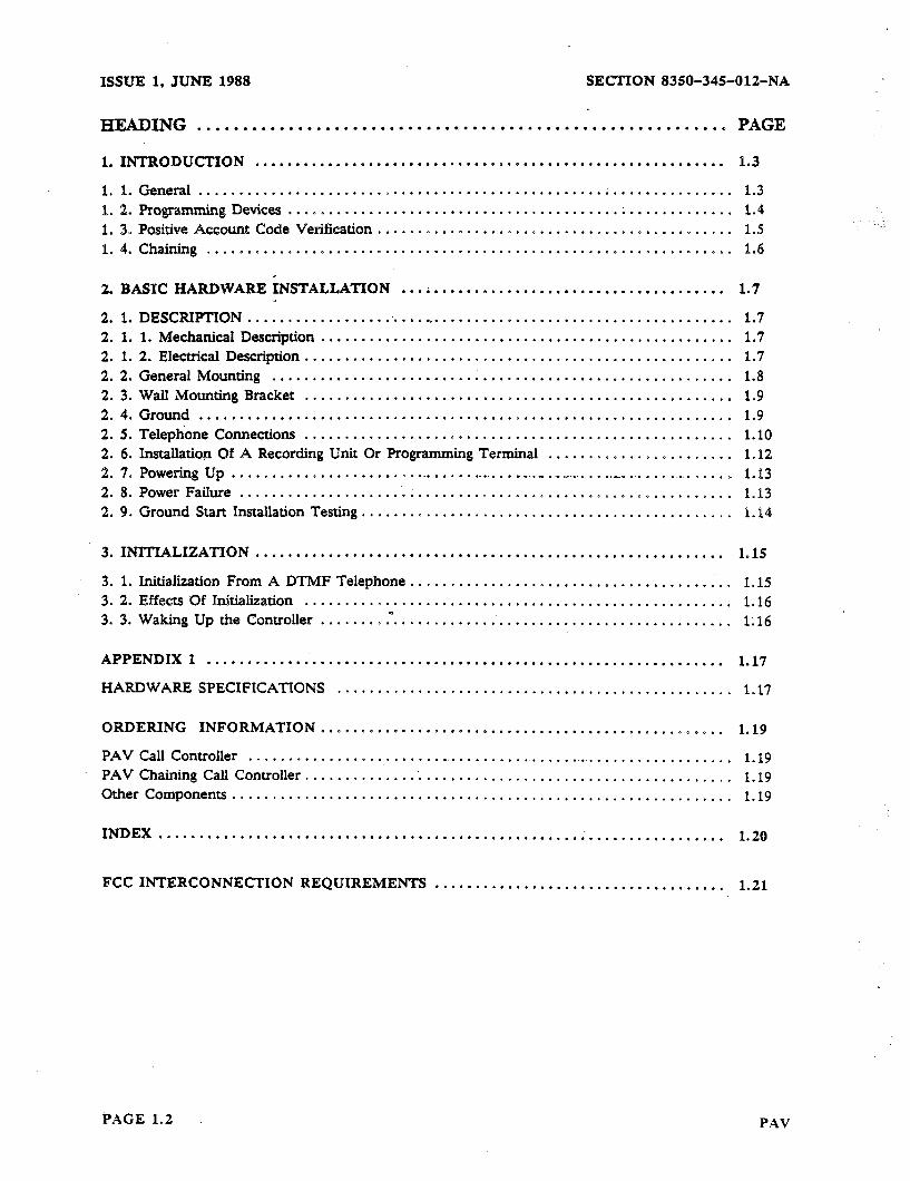
1. INTRODUCTION .......................................................... 1.3
1. 1. General .................................................. . ............... 1.3 1. 2. Programming Devices ....................................................... 1.4 l.3.PositiveAccountCodeVerification ............................................ 1.5 1. 4. Chaining ................................................................. 1.6
2. BASIC HARDWARE INSTALLATION ... . .................................... 1.7
2. 1. DESCRIPTION ............................................................ 1.7 2. 1. I. Mechanical Description ................................................... 1.7 2. 1. 2. Electrical Description ..................................................... 1.7 2. 2. General Mounting .......... . .............................................. 1.8 2. 3. Wall Mounting Bracket ..................................................... 1.9 2. 4. Ground .................................................................. 1.9 2. 5. Telephone Connections ..................................................... 1.10 2. 6.InstallatiosaOfARecordingUnitQrProgrammingTerminal ....................... 1.12 2. 7. Powering Up .......................................... . ........... ._ ................ 1.13 2. 8. Power Failure ............................................................. 1.13 2. 9. Ground Start Installation Testing .............................................. 1.14
3. INITIALIZATION .,...............,....................... . . . . . . . . . . . . . . . . . 1.15
3. 1. Initialization From A DTMF Telephone ........................................ 1.15 3. 2. Effects Of Initialization ..................................................... 1.16 3.3. WakingUptheController.. ..... mP,. ........................................ 1.16
APPENDIX 1 ................................................................ 1.17
HARDWARE SPECIFICATIONS ................................................. 1.17
ORDERING INFORMATION 0.00.00.**90a*00.0..a............... ..D...*.*OODD. 1.19
PAVCall Controller ............................................................ 1.19 PAV Chaining Call Controller ...................................................... 1.19 Other Components .............................................................. 1.19
INDEX . . . . . . . . . . . . . . . . . . . . . . . . . . . . . . . . . . . . . . . . . . . . . . . . . . . . . . . . . ..*.......... 1.20
FCC INTERCONNECTION REQUIREMENTS . . . . . . . . . . . . . . . . . . . . . . . . . . . . . . . . . . . . 1.21
PAGE 1.2 PAV
SECTION 8350-345012-NA ISSUE 1, JUNE 1988
1, INTROlXJCTION _ 1. 1. General
The SMART- 1 Telephone Controller is a simple, compact and versatile telephone con- troller providing:
Versatile Programming Four, or two line, or one line capacity Automatic Route Selection (ARS) Speed Call capacity of either 100, or 1000 Handles Loop Start Or Ground Start Telephone Lines Off-Hook Redial Remote Maintenance And Programming Compatible With Rotary Or DTMP Telephones and Telephone Offices Battery Back-up Of Customer’s Memory Separate Program Access Code To Allow Customer Speed Call Update/Maintenance Progress Tones Available For Call And Route Progress Programmable For Account Code Change On Route Change Compliance with FCC Parts 68 and 15 Separate program entry to allow customer update and maintenance of PAV lists Progress tones programmable on a route by route basis Useable with Centrex Lines Useable behind a PBX/PABX Hot Line operation
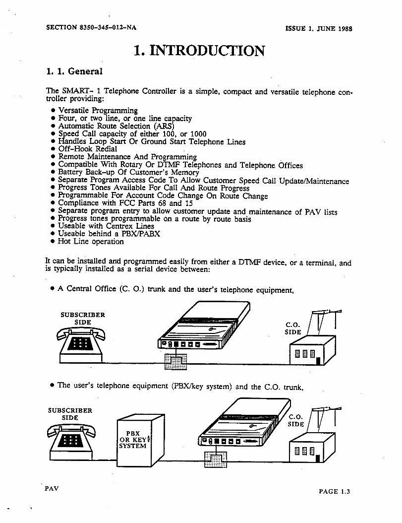
It can be installed and programmed easily from either a DTMP device, or a terminal, and is typically installed as a serial device between:
l A Central Office (C. 0.) trunk and the user’s telephone equipment,
SUBSCRIBER SIDE
l The user’s telephone equipment (PBX/key system) and the C.O. trunk,
n
PAV PAGE 1.3
ISSUE 1, JUNE 1988 SECTION 8350-34%012-NA
1 0
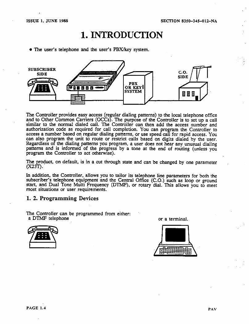
l The user’s telephone and
SUBSCRIBER SIDE
INTRODUCTION the user’s PBXkey system.
The Controller provides easy access (regular dialing patterns) to the local telephone office and to Other Common Carriers (OCCs). The purpose of the Controller is to set up a call similar to the normal dialed call. The Controller can then add the access number and authorizatiow code as required for call completion. You can program the Controller to access a number based on regular dialing patterns, or use speed call for rapid access. You can also program the unit to route or restrict calls based on digits dialed by the user. Regardless of the dialing patterns you program, a user does not hear any unusual dialing patterns and is informed of the progress by a tone at the end of routing (unless you program the Controller to act otherwise).
The product, on .default, is in a cut through state and can be changed by one parameter (x23T). .
In addition, the Controller, allows you to tailor its telephone line parameters for both the subscriber’s telephone equipment and the Central Office (C.O.) such as loop or ground start, and Dual Tone Multi Frequency (DTMF), or rotary dial. This allows you to meet most situations or user requirements.
1. 2, Programming Devices
The Controller can be programmed from either: a DTMF telephone or a terminal.
. . .
PAGE 1.4 PAV

SECTION 8350-345012-NA ISSUE 1, JUNE 1988
1. INTRODUCTION 1. 3. Positive Account Code Verification
The Controller can be programmed to require an Account Code before allowing a call. These Account Codes can be assigned to each individual person using the telephone lines connected to the Controller. These Account Codes can vary according to the route used as selected by the Controller. In addition, the Account Codes will appear on any Call Detail Records (CDR) output by the Controller through its RS-232 port. These records are valu- able when determining billing information, call cost analysis or traffic patterns.
If you wish to assign Account Codes that can be verified to persons using the the tele- phone lines connected’to the Contrcller, you will want to configure the unit as a Control- ler with Positive Account Code Verification (PAV). For call screening/toll control pur- poses this will limit you to one set of tables (Primary). The Alternate tables are used for ike Verifiable Account Codes.
_.
Should you not require Positive Account Code Verification you should configure the as a Controller without PAV. .
For more information on the PAV Controller see POSlTMZ ACCOUNT CODE ‘I-IONS in MANUAL 2.
unit
OP-
PAV PAGE 1.5
ISSUE 1, JUNE 1988 SECTION 835&I-345-012-NA
1. INTRODU~ON’ 1. 4. Chaining
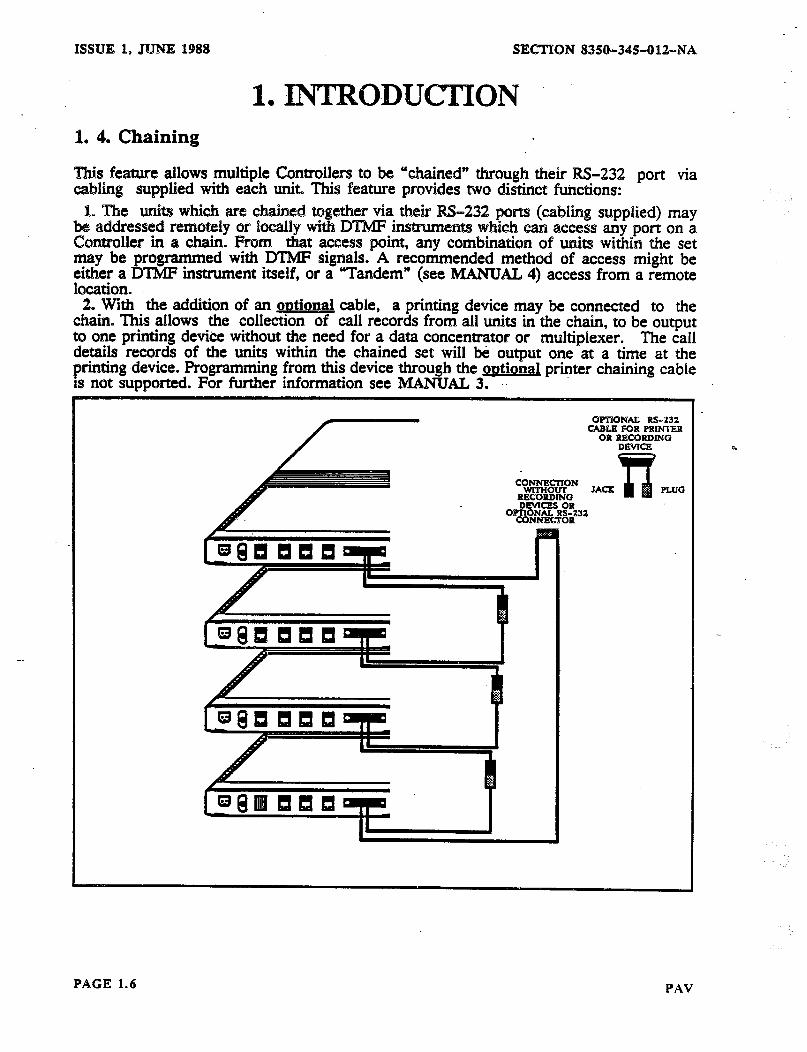
This feature allows multiple Controllers to be “chained” through their M-232 cabling supplied with each unit This feature provides two distinct functions:
port via
1. The units which are chained together via their IS-232 ports (cabhng supplied) may be addressed remotely or %ocally with DTMF instruments which can access any port om a Controller in a chain. From that access point, any combination of units within the set may be programmed with DTMF signals. A recommended method of access might be either a DTMF instrument itself, or a “Tandem” (see MANUAL 4) access from a remote location.
2. With the addition of an outionai cable, a printing device may be connected to the chain. This allows the collection of call records from all units in the chain, to be output to one printing device without the need for a data concentrator or multiplexer. The call details records of the units within the chained set will be output one at a time at the printing .device. Programming from this device through the gwtional printer chaining cable is not supported. For further information see MANUAL 3. ‘.
QmTONAL Rs-532 CABLE FOR PRIMTER
OR RRCORD6NG
JACX PLUG
2
PAGE 1.6 PAV
SECTION
2 l
8350-34%OlZ-NA ISSUE 1, JUNE 1988
BASIC HARDWARE INSTALLATION 2. 1. DESCRIPTION
2. 1. 1. Mechanical Description
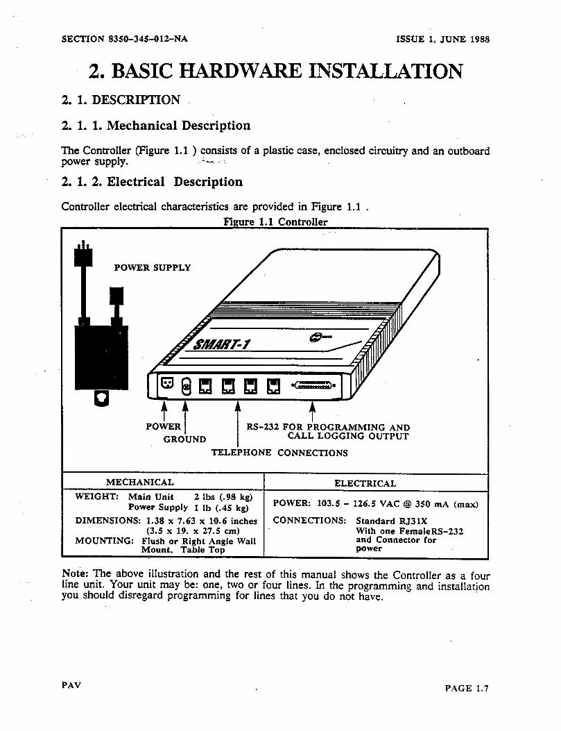
The Controller (Figure 1.1 ) consists of a plastic case, enclosed circuitry and an outboard power supply. .*-. . .
2. 1. 2. Electrical Description
Controller electrical characteristics are provided in Figure 1.1 .
POWER SUPPLY
DIMENSIONS: 1.38 x 7.63 x 10.6 inches CONNECTIONS: Standard RJ3 1X With one FemaleRS-232
MOUNTING: Flush or Right Angle Wall and Connector for Mount, Table Top
Note: The above illustration and the rest of this manual shows the Controller as a four line unit. Your unit may be: one, two or four lines. In the programming and installatjon you should disregard programming for lines that you do not have.
PAV PAGE 1.7
ISSUE 1, JUNE 1988 SECTION 8350~34501%NA
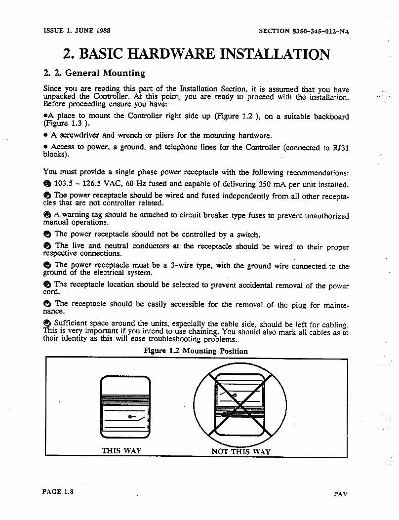
2, BASIC lE!IMtDWARE INSTAlYLA~ON 2. 2. General Mounting
Since you are reading this part of the Installation Section, it is assumed that you have unpacked the Controller. At this point, you are ready to proceed with the installation. Before proceeding ensure you have:
.
oA place to mount the Controller right side up (Figure 1.2 ), on a suitable backboard (Figure 1.3 ). o A screwdriver and wrench or pliers for the mounting hardware. @ Access to power, a ground, and telephone lines for the Controller (connected to RI31 blocks).
You must provide a single phase power receptacle with the following recommendations: @ 103.5 - 126.5 VAC, 60 Hz fused and capable of delivering 350 mA per unit installed. QJ The power receptacle should be wired and fused independently from all other recepta- cles that are not controller related.
A warning tag should be attached to circuit breaker type fuses to prevent unauthorized manual operations. @ The power receptacle should not be controlled by a switch. @ The live and neutral conductors at the receptacle should be respective connections. @ The power receptacle must be a 3-wire type, with the ground ground of the electrical system.
wired to their proper .
wire connected. to the.
@ The receptacle location should be selected to prevent accidental removal of the power cord. @ The receptacle should be easily accessible for the removal of the plug for mainte- nance.
Syfficient space around the units, especially the. cable side, should be left for cabling. This 1s very important if you intend to use chaining. You should also mark all cables as to their identity as this will ease troubleshooting problems..
Plgure I.2 Mounting Position
THIS WAY NOT THT,C WAY
PAGE 1.8 PAV

SECTION 8350-345-012-NA ISSUE 1, JUNE 1988
2. BASIC HARDWARE INSTALLATION For information on installing chaining see MANUAL 3.
The Controller can be mounted in one of two ways as shown in Figure 1.3 using the mounting. bracket shown in Figure 1.4 .
Figure 1.3 Mounting
WALL MOUNT BRACKET RIGHT ANGLE OPTION
(PN 8350-017) R
WALL MOUNTEDUNIT STANDARD FLUSH MOUNT
2. 3. Wall Mounting Bracket
Either mounting bracket has two wood screws and two holes in it to facilitate mounting. You should ensure that you have a solid surface such as l/2 inches (1.27 cm) plywood of sufficient size to mount the unit.
Figure 1.4 Mounting Brackets
FLUSH MOUNT BRACKET RIGHT ANGLE BRACKET
MOUNTING PLUGS
MOUNTING SCREWS FOR BRACKET
2. 4. Ground
You must provide a good proven ground and wire as shown in Figure 1.5 . You should also ensure that all equipment (recording devices, printers, etc.) are grounded at the same point.
PAV PAGE 1.9

ISSUE 1, JUNE 1988 SECTION 8350-345012-NA
2. BASIC HARDWARE INSTALLATION Figure 1.5 Ground Wisisg
2. 5. Telephone Connections
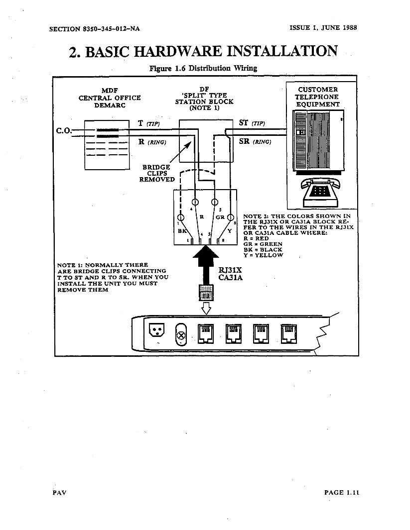
The telephone connections should be made at the distribution block on your side of the telephone protection units, following established procedures and techniques (Figure 1.6 ). Tylxcally, vhen you connect to the modular jacks in your building you will be on the protected sfde of the telephone connections (if you are not sure, you should check). Fngure 1.6 illustrates the USOC RJ3lX Connector and cable assembly as used by the Controller. The FIGURE also illustrates a typical distribution block set up. Note: the cemter bridging clips are not inserted on the station block. This means that the Controller acts as a connector between the left and right connection points on the Station Block in Figure 1.6 D
If you wire the Controller per Figure 1.6 it will when programmed, physically route calls through it, to the C.O.. This is done transnarentlv to the user, but all digits (whether DTI@ or rotary) dialed by the user can be &zreened and routed. This is done by splitting the user from the line when the user goes off-hook.
co. SIDE
Once enough digits have been screened, the Controller decides the routing and dialing patterns. Then the Controller outputs the proper dialing sequence to the CO..
SUBSCRIBER
. Once the digits have been sent to the C.O. the caller will be connected to the C.O..
PAGE 1.10 PAV
SECTION 8350-34%012-NA ISSUE 1, JUNE 1988
2. BASIC HARDWARE INSTmLATION Figure 1.6 Distribution Wtig
MDF CENTRAL OFFICE
DEMARC
’ SPL&YPE STATION BLOCK
(N&E 1)
T (TIP) = (TIP)
NOTE 1: NORMALLY THERE ARE BRIDGE CLIPS CONNECTING T TO ST AND R TO SR. WHEN YOU INSTALL THE UNIT YOU MUST REMOVE THEM
CUSTOMER TELEPHONE EQUIPMENT
NOTE 2: THE COLORS SHOWN IN THE RJ3lX OR CA3lA BLOCK RE- FER TO THE WIRES IN THE RJ31X OR CA31A CABLE WHERE: R=RED CR = GREEN BK = BLACK Y =YELLOW ,
PAV PAGE. 1.11
ISSUE 1. JUNE 1988 SECTION 8350-34%01%NA
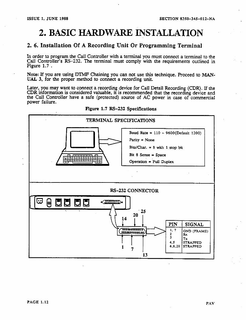
2, BASIC HARDWiiItE INSTALLATION 2. 6. Installation Of A Resording Unit Or Programning Terminal
h order to program the Call Controller with a terminal you must connect 8 termiflal to the Call Controller’s RS-232. The terminal must comply with the requirements outlined in Figure 1.7 D
Note: If you are using DTMF Chaining you can not use. this technique. Proceed to IMAW lL4.L 3, for the proper method to connect a recording unit.
Later, you may want to connect a recording device for Call Detail Recording (CDR). If the CDR information is considered valuable, it is recommended that the recording device and the Call Controller have a safe (protected) source of AC power in case of commercial power failure.
Figure 1.7 RS-232 Specifications
TERMINAL SPECIHCA’XTONS
= 8 with l-stop bit
Bit 8 Sense = Space
W-232 CONNECTOR
PAGE 1.12 PAV

SECTION 8350-345012-NA ISSUE 1, JUNE 1988
2 l BASIC HARDWARE INSTALLATION 2. 7. Powering Up
To power up’ the Controller simply plug it in as shown in Figure I.8 .
Figure 1.8 Powering Up
TO 115 VAC SOCKET POWER SUPPLY
2. 8. Power Failure
Should a power failure occur that disables the Controller (or the Controller fails) the user’s telephone will be directly connected to the CO. line. This means that the user will still have access to the telephone network, but the Controller will not screen or route calls.
SUBSCRIBER C.O. SIDE
PAV PAGE 1.13
ISSUE 1. J?JNE 1988 SECTION 8350-345-012-NA
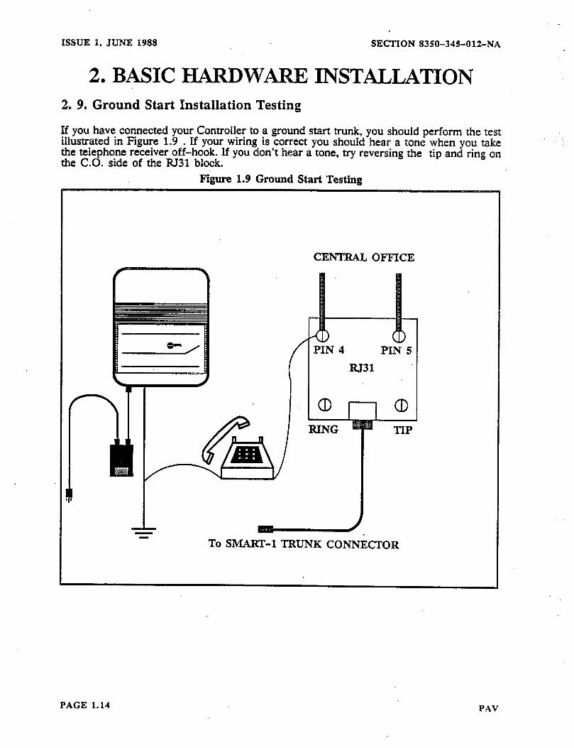
2, BASIC lilAlXDW= INSTALIATION 2. 9. Ground Start Installation Testing
If you have connected your Controller to a ground start trunk, you should perform the test illustrated in Figure 1.9 S If your wiring is correct you should hear a tone when you take the telephone receiver off-hook. If you don’t hear a tone, try reversing the tip and ring on the C.0. side of the RJ31 block.
Figure 1.9 Ground Start Testing
1_ To SMART-1 TRUNK CONN&TOR
PAGE 1.14 PAV
SECTION 8350-345-01%NA ISSUE 1, JUNE 1988
3. INITIALIZATION Before performing any further installation you should power the controller(s) up for 24 hours to allow the back-up batteries to charge filly.
: In~i~~~z program the Con?oiler the first time or YOU wish to reset the Controller to its be a only.
ueq you must inmallze the unit. This can be done from a DTMF telephone
3. 1. Initialization From A DTMF Telephone
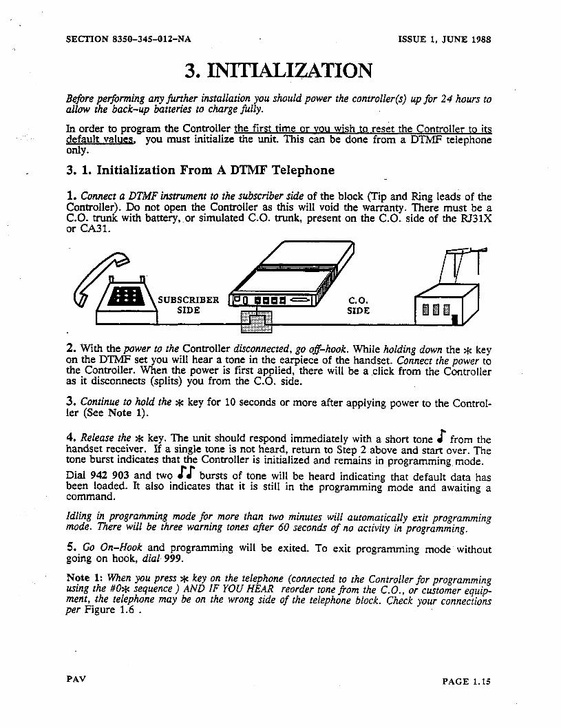
1. Connect a DTMF instrument to the subscriber side of the block (Tin and Ring leads of the Controller). Do not open the Controller as this will void the w&anty. ,Th&e zrtAy with battery, .or simulated C.O. trunk, present on the C.O. side of
.
n
must be a the RJ31X
SUBSCRIBER
2. With the power to the Controller disconnected, go o&hook. While holding down the * key on the DTMF set you will hear a tone in the earpiece of the handset. Connect the ljower to the Controller. When the power is first applied, there will be a click from the Controller as it disconnects (splits) you from the C.O. side.
3. Continue to hold the * key for 10 seconds or more after applying power to the Control- ler (See Note 1).
4. Release the * key. The unit should respond immediately with a short tone E from the handset receiver. If a single tone is not heard, return to Step 2 above and start over. The tone burst indicates that the Controller is initialized and remains in programming. mode. Dial 942 903 and two EE bursts of tone will be heard indicating that default data has &zf;$ed. It also indicates that it is still in the programming mode and awaiting a
.
Idling in programming mode for more than two minutes will automatically exit programming mode. There will be three warning tones after 60 seconds of no activity in programming.
5. Go On-Hook and programming will be exited. To exit programming mode’ without going on hook, dial 999.
Note 1: When you press * key on the telephone (connected to the Controller for programming ustng the #O* sequence ) AND IF YOU HEAR reorder tone from the C.O., or customer equip- ment, the telephone may be on the wrong side of the telephone block. Check your connections per Figure 1.6 .
PAV PAGE 1.15
ISSUE 1, JUNE 1988 SECTION 8350-345012-NA
3. INITIALIZATION 3. 2. Effects Of Initialization
When you have initialized the Controller all dialing will be passed straight through it, to the CC.. The Controller will not attempt to analyze, route or screen calls.
3. 3. Waking Up the Controller
After initializing, you must wakeup the Controller. You murt be in programming mode to w&-up the Controller. If you are not in programmin g mode you should enter # 0 * , or from a terminal a <CR> to enter programming mode. Waking up the Controller for all ,trunks (while in programming), can be done by dialing 5238. This causes the Controller to:
*A E will be heard by the user, when the user makes a call. o Only respond to the programming command of # 0 % from a DTMF telephone or a
carriage return (<CR>) from a terminal. e Set all trunks to loop start, DTMF 8 Route all no-n 1 + (local) calls go via DDD @ Route all 911, f-411, l-555, l-area code-555, l-800 calls go via DDD Q Route all other l+ (long distance) calls go via CCC e Route all local calls after the first digit is dialed e Route all l+ calls after fourth digit dialed.
FOR ADDITIONAL PROGRAMM@=G
LvPROCEED TO ikXANUAL 2~
FOR C-G INSTALLATION AND PROGRAMMING
ePROCEED TO MANUAL 3-a
PAGE 1.16 PAV

SECTION 8350-345-012-NA ISSUE 1, JUNE 1988
APPENDIX 1 TABLE Al-l
HARDWARE SPECIFICATIONS
SPECIFICATION MIN. TYP. MAX. UNITS
FCC RINGER EOUIVALENCE .7 B
IDLE LINE. LOOP START
RINGER IMPEDANCE: 15 - 60 HZ, 70 -1lOVAC 10 20 K n
20 - 3500 HZ, 10 V 1 MQ
RINGING SENS~TWITYZI~ - 60 HZ 40 VOLTS
LEAKAGE: TIP TO RING, 1OOV 20 Ma
TIP TO EARTH, 1OOV 20 Ma
OFF-HOOK CURRENT 15 80 MA
IDLE LINE. GROUND START
SENSING RESISTANCE: Tip to earth 36 40 45 K n
OPBN CIRCUIT VOLTAGE: to Tip Ring -22 -25 -28 VOLTS
GROUNDING VOLTAGE -5 0 +lO VOLTS
TIME TO RECOGNIZE TIP-GROUND 10 150 MS
RESISTANCE: Sending Ring-Ground n/a
BATTERY FEED
OPEN CIRCUIT VOLTAGE 22 24 26 VOLTS
FEED RESISTANCE 550 600 650 n
BALANCE: DC 36 40 DB
SHORT CIRCUIT CURRENT 50 MA
TERMINATION
RESISTANCE: DC, 20 MA 200 300 sz DC, 40 MA 200 300 n AC, 300 - 3000HZ 550 600 650 R
mm Loss: 600 OHMS, 20 MA 20 26 DB
OPERATING CURRENT 13 80 MA
PAV PAGE 1.17
ISSUE 1, JUNE 1988 SECTION 8350-345-012-NA
APPENDIX 1 TBLE Al-l
I-XARDWmE SPECIFICATIONS
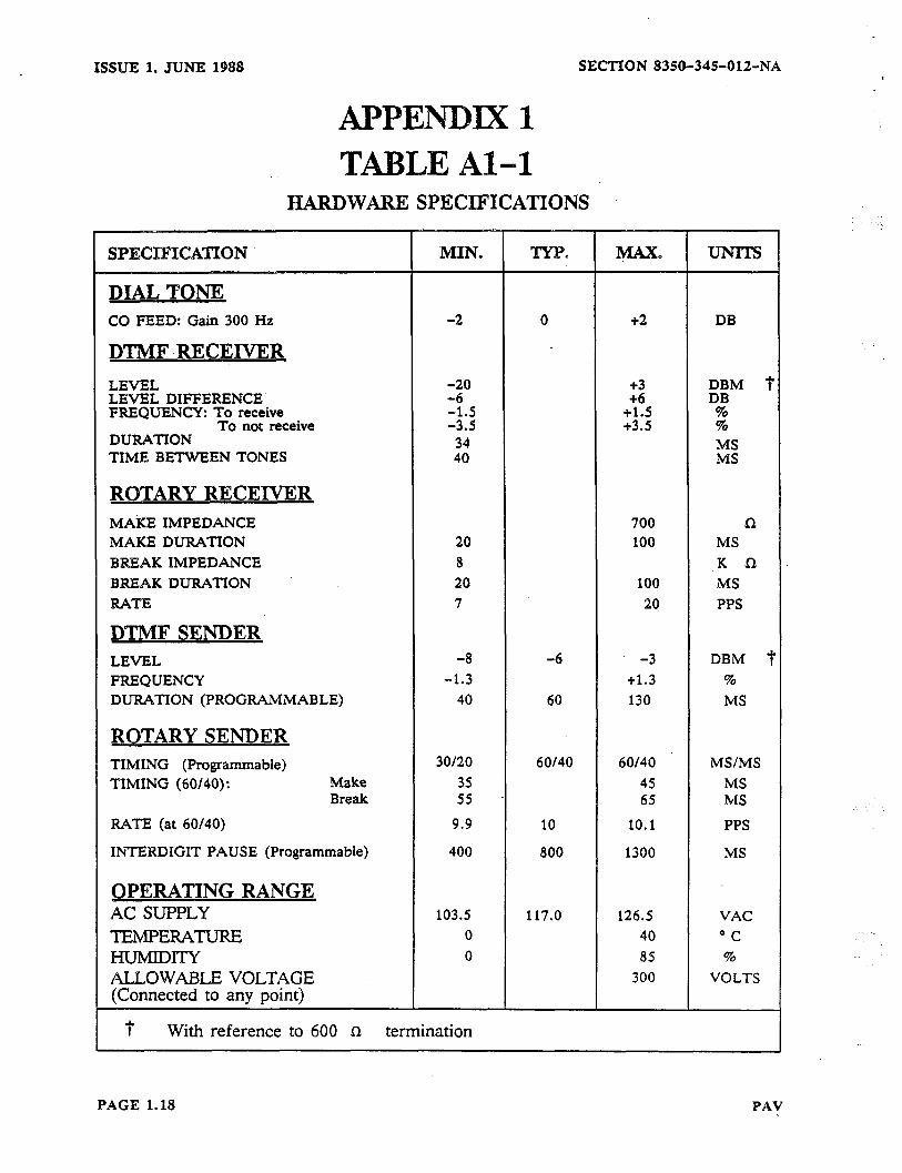
DIAL TONE CO FEED: Gain 300 Hz
DTMF .RECElVER
LEVEL LEVEL DIFFERENCE FREQUENCY: To receive
To not receive DURATION TIME BETWEEN TONES
ROTARY RECEIVElR M&E IMPEDANCE MAKE DURATION BREAK IMPEDANCE BREAK DURATION RATE
DTMF SENDER
20 7
100 20
‘MS PPS
LEVEL -8 -6 -3 DBM j FREQUENCY -1.3 +1.3 % DUIWTION (PROGRAMMABLE) 40 60 130 MS
ROTARY SENDER TIMING (Programmable) TIMING (60/40): Make
Break
RATE (at 60/40)
INTERDIGIT PAUSE (Programmable)
OPERATING RANGE Ac SUPPLY TIZMPERAW mw ALLOWABLE VOLTAGE (Connected to any point)
30120 60140 60140 MS/MS 35 45 MS 5s 65 MS
9.9 10 10.1 PPS
400 800 1300 MS
103.5 117.0 126.5 VAC 0 40 “C 0 85 %
300 VOLTS
With reference to 600 CI termination
PAGE 1.18 PAV

SECTION 8350-345-012-NA ISSUE 1, JUNE 1988
APPENDIX 1 TABLE Al-2
ORDERING INFORMATION The Controller is available as a single or dual or four line unit, complete with power supply, cabling; documentation and can be ordered under the following part numbers:
PAV Call Controller For U.S. applications: SMART-1 Call Controller (four line unit) SMART-l Call Controller (two line unit) SMART-l Call Controller (one line unit) For Canadian applications: SMART-1 Call Controller (four line unit) SMART-l Call Controller (two line unit) SMART-l Call Controller (one line unit)
PAV Chaining Call Controller For U.S. applications: SMART-l Call Controller (four line unit) SMART-l Call Controller (two line unit) SMART-l Call Controller (one line unit) For Canadian applications:
8350-005 8350-006 8350-003-PAVAXX
8350-005-CDN 8350-006-CDN 8350-003-PAVCXX
SMART-l Call Controller (four line unit) SMART-l Call Controller (two line unit) SMART-l Call Controller .(one line unit)
The Call Controller Cables can be ordered as:. SMART-l Call Controller Chain Cable SMART-l Call Controller Chaining Printer Cable
Call Controller documentation is: -_ Hardware Installation General Programming Guide Chaining Installation and Programming Technical Guide
Other Components
8350-OOl-CHNAXX 8350-002-CHNAXX 8350-003-CHNAXX
8350-OOl-CHNCXX 8350-002-CHNCXX 8350-003-CHNCXX
8350-026 8350-027
8350-345-012-NA 8350-345-013-NA 8350-345-014-NA 8350-345-o 15-NA
You can order the- following components: Wall Mount Bracket Right Angle Mounting Bracket Power Pack RJ31X Cable
8350-010 8350-017 8350-O 12 8350-013
PAV PAGE 1.19

ISSUE 1, JUNE 1988
C Chaining, 1.6
Electrical, 1.7, 1.8
FCC, 1.21
HEED SERVICE, 1.1
Ground Start Testing, 1.14
H HARDWARE SPECIFICATIONS, 1.17
I Installation of a Recording Unit, 1.12
Mechanical Description. 1.7
Electrical Description, 1.7
0 ORDERING INFORMATION; 1.19
Positive Account Code Verification, 1.5
Power Failure. See Power Up
Power Up, 1.13
SECTION 8350-34%012-NA >
PAGE 1.20 PAV
SECTION 8350-345012-NA
FCC INTERCONNECFION
ISSUE 1, JUNE 1988
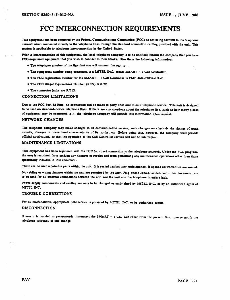
REQUIREMEmS This asuipmant hu been approved by the Federal Communications Cornmiss’ ton (FCC) es not being harmful to the telephone network when connected directly to the telephone lines through the standard connection cabling provided with the unit. This section is applicable to telephone intersottnection in the United States.
Prior to interconnection of this equipment. the local teiephotte company is to be notif3edt Inform tits company that you have FCC-registered equipment that you wish to Connect to their trunks. Give them the foIlowing information:
l The telephone number of the line that you will connect the unit to,
l The equipment number being connected is a MITEL INC. model SMART - 1 Call Controller,
l The FCC registration number for the SMART - 1 Call Controller is EMP 46K-72059-L&E.
l The FCC Ringer Equivalence Number (BEN) is 0.7B,
l The connector jacks are BJ31X.
CONNECTION LXMITATIONS
Due to the FCC Part 68 Rule, no connection can be made to party lines and to coin telephone service. This unit is designed to be used on standard-device telephone lines. If there are any questions about the telephone line, such as how many pieces of equipment may be connected to it, the telephone company will provide this information upon request.
NETWORK CHANGES
The telephone company may make changes to its communication service: such changes may include the change of tNI&
circuits, changes in opwatiod characteristics of its trunks, etc. Before doing this, however, the company shall provide official notification. so that the operation of the Call Controller service will not be interrupted.
MAINTENANCE LIMITATIONS
This equipment has been registered with the FCC for direct connection to the telephonu network. Under the FCC program, the user is restricted from making any changes or repairs and from performing any maintenance operations other than those specifically included in this document.
There are no user repairable parts within the unit. It is sealed against user maintenance. If opened ail warranties are voided.
No cabiing or wiring changes within the unit are permitted by the user. Plug-ended cables, as detailed in this document, are to be used for all external connections between the unit and the unit and the telephone interface jack.
Power supply components and cabling are only to be changed or maintained by MITEL INC. or by an authorized agent of MITEL INC.
TROUBLE CORRECTIONS
For all malfunctions. appropriate field service is provided by MITEL INC. or its authorized agents.
DISCONNECTION
If ever it is decided to permanently disconnect the SMART - 1 Gail Controller from the present line. please notify the telephone company of this change
PAV PAGE 1.21

. . . . . . .._ _ __-.. ;-,-.
ISSUE 2, AUGUST 1988 SECTION 8350-~3%S-O13-F&%~
SMART-1 ,..:.
SMAJXT-1 CALL CONTROLLER ,
MAN&J&L2 i. .
GENERAL PROGRAMMING GUIDE
@ Copyright 19S8 MlTEL INC. All rights rcscrved. @ Regisvxcd Trademark of MITEL Corporation
FfMTED m CANADA
SECTION 8350-345-013rNA ISSUE 2, AUGUST 1988
HEADING . . . . . . . . . . . . . . . . . . . . . . . . . . . . . . . . . . . . . . . . . . . . . . . . . . . . . . . . . . PAGE
I. GENERAL ....................................................... 2.6 1. 1. About This MANUAL ..................................................... 2.6
1. 2. As Outlined In MANUAL 1 ................................................ 2.6
1. 3. Wakeup The Controller .................................................... 2.6
2. GENERAL NOTES ON PROGRAMMING ............................ 2. 1. 2. 2. 2. 3. 2. 4.
2. 5. 2. 6. 2. 7. 2. 8. 2. 9. 2. 2. 2.
3. 3.
4. 4. 4. 4. 4. 4. 4.
4. 4. 4. 4. 4. 4.
4. 4. 4. 4. 4.
Programming With a DTMF Telephone .......................................
Terminating Variable Length Entries ..........................................
Acknowledgment Tones ....................................................
Typical Resulting Controller Action ...........................................
Terminating A Variable Length Entry .........................................
Programming With a Terminal ...............................................
Changing Terminal Program Security Code .....................................
Legal and Illegal Entries ....................................................
TandemMode (942 908)............................. ......................
2.7 2.7 2.7 2.7 2.8 2.9 2.9
2.9 2.9 2.10 2.10 2.10 2.10
10. Cloning (942 906) .......................................................
ll.Data Verification(902) ...................................................
12. Special Functions ........................................................
SELECTING THE CONTROLLER TYPE ............................. 2.12 1. Specifying the Unit As A Call Controller Or A PAV Controller .................... 2.12
SYSTEM WIDE DATA . . . . . . . . . . . . . . . . . . . . . . . . . . . . . . . . . . . . . . . . . 0 0 0 . 1.
2.. 3. 4.
5. 6. 7. 8.
9.
General .................................................................. Programming Speed Calls ...................................................
Defining The Maximum Number Of Speed Calls ................... I. ..........
Setting up a Speed Call Method 1 ...........................................
Setting up a Speed Call Method 2 ...........................................
To Use A Speed Call Number From a DTMF Phone ............................
To Change the Speed Call So It Can Be Accessed From a Rotary Dial Phone .......
If You Wish To Delete The Old Speed Call Access Code ........................
To Use The New Number From a Rotary Dial Phone ............................
10. Re-Order Tone Supplied By the Controller ...................................
11. Trunks To Be Monitored For Call Detail Recording ............................
12.RS-232 Baud Rate ....................................................... 13. Nulls After A Carriage Return ...............................................
14. Print Out Incoming Calls ..................................................
15. Print Format For CDR ....................................................
16. RoutetoMonitorfosCDR ................................................
17. Route Progress Tone Length ...............................................
2.13 2.13 2.13 2.13 2.13 2.15
2.15
2.15 2.15 2.15 2.16 2.16 2.16 2.16 2.16 2.17 2.17 2.17
PAGE - 2.2 PAV

ISSUE 2. AUGUST 1988 SECTION 8350;345-013~NA
HEADING . . . . . . . . . . . . . . . . . . . . . . . . . . . . . . . . . . . . . . . . . . . . . . . . . . . . . . . . . . PAGE
5. LINE AND TRUNK OPTIONS . . . . . . . . . . . . . . . . . . . . . . . . . . . . . . . . . . . . . 2.18 5. 1. General .................................................................
5. 2. Type Of Dialing And Trunk ................................................
5. 3. Rotary Dialing Rates .......................................................
5. 4. DTMF Dialing Rates .......................................................
5. 5. ‘On Hook Time ..............................................................
5. 6. Flash Allowed Time .......................................................
5. 7. Time Between Trunk Release And Next Attempt to Connect. .....................
5. 8. Ground Start Attempts .....................................................
5. 9.GroundStartAttemptTimer.. ..............................................
5. 10. Off-Hook Digit Refusal Time ...............................................
5. 11. User DialTone ..........................................................
5. 12. Interdigit Time Out Subscriber Side .................. :: .....................
5. 13. Interdigit Time Out On 0+ Calls ............................................
5. 14. Interdigit Time Out On Ol+ Calls ...........................................
5. 15. Rotary Interdigit Pause On Calls On Outgoing Dialing ...........................
5. 16. Off-HookTone ..........................................................
5. 17. Incoming Call Detection ............................ .: .....................
5. 18. Controller Operation On Off-Hook ..........................................
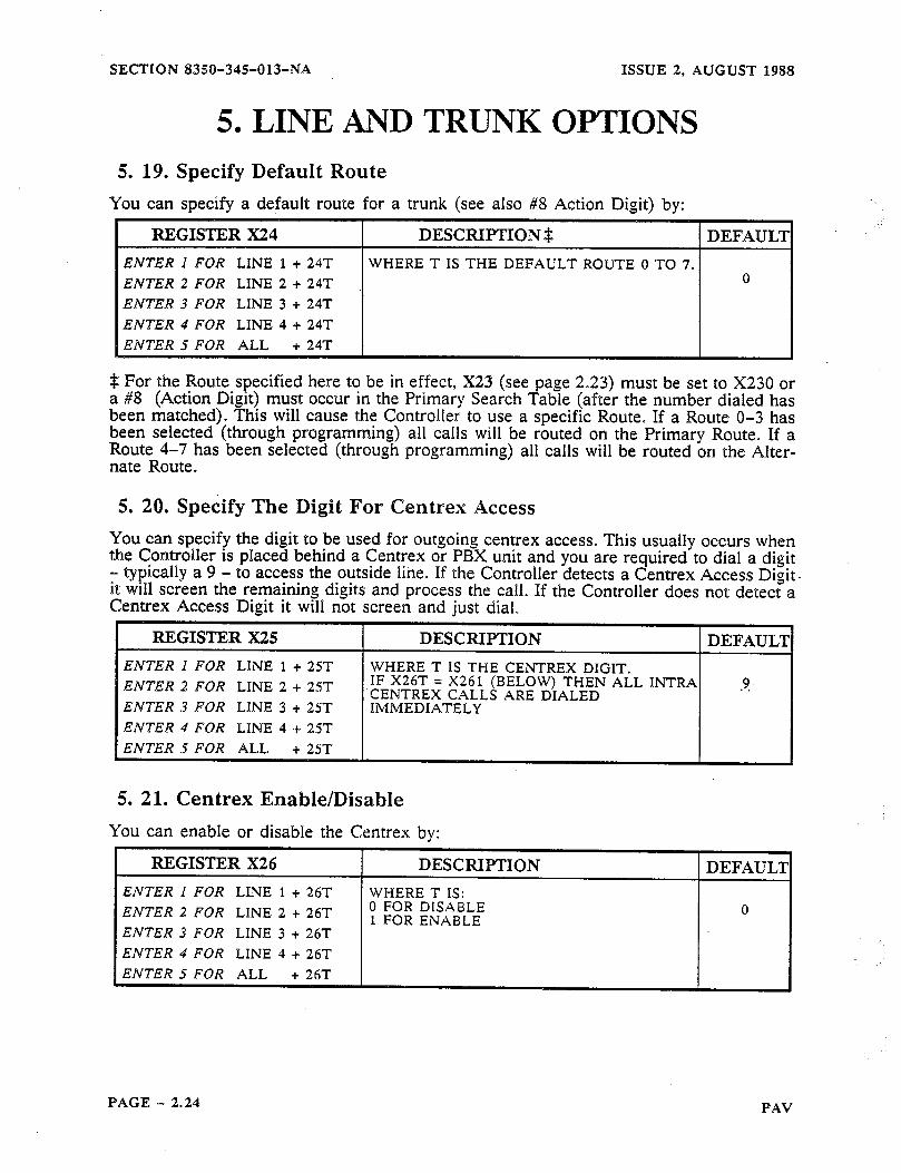
5. 19. Specify Default Route ......................................................
5.20. SpecifyTheDigitForCentrexAccess ........................................
5. 21. Centrex Enable/Disable ................... ! ...............................
5. 22. Time To Auto-Answer .....................................................
5. 23. Wait For Security Code Timer ..............................................
5. 24. Incorrect/Failed Security Code Trunk Lockout Timer ...........................
5. 25. Off-Hook Recognition Timer ...............................................
5. 26. Tip Ground Application Recognition Timer ...................................
5. 27. Digit Recognition On Outgoing Calls .........................................
5. 28. Digit Recognition On Incoming Calls .........................................
5. 29. Tip Ground Removal Timer ................................................
6. PRIMARY SEARCH TABLES ...................................... 6. 1. General ..........................
6. 2. Primary Search Tables ..............
6. 3. Warning ..........................
6. 4. Digits In A Table ..................
6. 5. Default Data ......................
6. 6. Search Tables 801 .................
6. 7. Search Tables 803 .................
6. 8. Search Tables 804 .................
6. 9. Search Tables 807 .................
6. 10. Search Tables 808 ................
2.18
2.18
2.18
2.19
2.19
2.20
2.20
2.20
2.21
2.21
2.21
2.22
2.22
2.22
2.22
2.23
2.23
2.23
2.24
2.24
2.24
2.25
2.25
2.25
2.26
2.26
2.26
2.27
2.27
2.28 ...................................... 2.28
...................................... 2.28
....................................... 2.28
........................... . .......... 2.28
...................................... 2.31
...................................... 2.31
...................................... 2.31
...................................... 2.31
...................................... 2.32
...................................... 2.32
PAV PAGE, - 2.3
SECTION 83§0-34%OIJ-NA ISSUE 2, AUGUST 1988
HEADING .O..e........................ . . . . . . . . ..e.*..*.*....o..e... PAGE 6. 11. SearchTables 810 ....................................................... 2.32
6. 12. Search Tables 811 ....................................................... 2.32
6. 13. Special Note ............................................................ 2.32
6. 14. Warning.............................~ .................................. 2.32
7. COMMON OPTION DATA. o a s e o 0 0 a e o 0 . 0~.~.0~..~~00~0~0~0~~~~~~~~ ~ 2.33 7.1.UserAreaCode .......................................................... 2.33
7. 2. Machine Identifier ........................................................ 2.33
7. 3. Auto-Answer Security Code ................................................ 2.33
7. 4. Terminal Program Security Code ............................................. 2.33
8. ROUTE PARAMETER PROGRAMMING ..o....oo.i....e.........*a. 8. 1. General .................................................................
8. 2. Primary And Alternate Routes ...............................................
8. 3. Primary And Alternate Destination Number Format .............................
8. 4. Route Progress Tones ......................................................
8. 5. NumberofAccountCodeDigits ...............................................
8. 6. Account Code Entry Inter-Digit Timer ........................................
8. 7. AccountCodeType ..................... . .... . ............................
8. 8. Action on Call Failure .....................................................
8. 9. Account Code Warning Tones ...............................................
8. 10. Account Code Confirmation And Reroute Tones . . . _. . . . . . . . . . . . . . . . . . . . . . . . . _ . .
9. CALL CONTROL DATA ENTRY 0~~00~~000~00000.~....~.~~~.~.~~.~~~ 9. 1.
9. 2.
. 9. 3.
9. 4.
9. 5.
9. 6.
9. 7.
9. 8.
9. 9.
General .................................................................
Route Strings.. ............................................................
Access Control Sequences (6RS) .............................................
A and B Dial Tone Timers ............... . .................................
Name Of Route ...........................................................
Access Number For OCC Telephone Network ..................................
Authorization Number .....................................................
Dummy AccountCode ......................................................
2.34 2.34
2.34
2.34
2.35
2.36
2.36
2.37
2.38
2.39
2.40
2.$% 2.41
2.41
2.41
2.43
2.44
2.44
2.44
2.45
Centrex Number . . . . . . . . . . . . . . . ..~.....~.....~............................ 2.45
10. POSITIVE ACCOUNT CODE ORIONS o s s 10. 1. Description ................................
10. 2. Specifying the Unit As A Controller Or PAV .....
10. 3. Number Of Account Codes ...................
10. 4. PAV List Maintenance Code ...................
10. 5. Action Digits ...............................
10. 6. String Data .................................
10. 7. Programming Positive Account Codes ...........
..................... ..e. 2.46 ............................ 2.46
............................ 2.46
............................ 2.46
............................ 2.47
............................ 2.47
............................ 2.48
............. ..r........i ... 2.48
PAGE - 2.4 PAV
ISSUE 2, AUGUST 1988 SECTION 8350-345-013-NA
HEADING ..........................................................
APPENDIX 1 - SYSTEM INFORMATION .............................. Al. 1 GENERAL ..............................................................
Al, 2 Print Format .............................................................
Al. 3 MITEL Format ...........................................................
Al. 4 SMARTFormat ..........................................................
APPENDIX 2 - SITE INFORMATION ..................................
PAGE
2.50 2.50
2.50
2.50
2.50
2.53
CONTROLLERSITE FORM ..................................................... 2.54
SEARCH TABLE .............................................................. 2.56
SEARCH TABLE FORM ........................................................ 2.57
SPEEDCALL .................................................................... 2.58
Setting up a Speed Call Method 1 ................................................. 2.58
Setting up a Speed Call Method 2 .................................................... 2.58
SPEED CALL FORM ........................................................... 2.59
POSITIVE ACCOUNT CODE .................................................... 2.60
Programming Positive Account Codes ............................................... 2.60
POSITIVE ACCOUNT CODE FORM ............................................... 2.61
INDEX ............................................................. 2.62
PAV PAGE - 2.5
SECTION 8350-345013-NA ISSUE 2, AUGUST 1988
1. GENERAL
1. 1. About This MANUAL
This manual shows the Controller as a four line unit. Your unit may be one, two or four lines. While programming you should disregard programming for lines that you do not have.
1. 2. As Outlined In MANUAL 1
In order to program the Controller: You must have powered up the unit for at least 24 hours to charge the memory battery.
You must have initialized the unit if this is an initial installation
You must have either a terminal, or a DTMF telephone-.connected to the Controller.
You must have C.O. trunk with battery present, or a simulated CO.. trunk connected to the line you are programming the Controller with (this is not required if you are using a terminal) D
1. 3. Wakeup The Controller
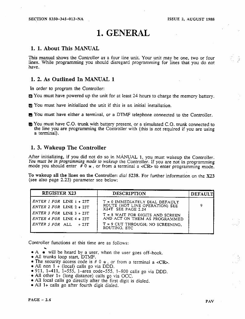
After initializing, if you did not do so in MANLJAL 1, you must wakeup the Controller. You mwf be in paagramnsirog m&e %o wakeup the Controller. If you are not in programming mode you should enter # 0 * s or from a terminal a xCfQ> to enter programming mode.
To wakeup all the lines on the Controller: dial 5238. For further information on the X23 (see also page 2.23) parameter see below:
REGISTER X23 I DESCRIPTION
ENTER I FOR LINE 1 + 23T T = 0 IMMEDIATELY DIAL
ENTER 2 FOR LINE 2 + 23T ROUTE (HOT LINE OPERATION) SEE 9 X24T SEE PAGE 2.24
ENTER 3 FOR LINE 3 + 23T T = 8 WAIT FOR DIGITS AND SCREEN ENTER 4 FOR LINE 4 + 23T AND ACT ON THEM AS PROGRAMMED
ENTER 5 FOR ALL + 23T T = 9 CUT THROUGH; NO SCREENING, ROUTING, ETC
Controller functions at this time are as follows:
l A .‘ will be heard by a user, when the user goes off-hook. l All trunks loop start, DTMF. l The security access code is # 0 * , or from a terminal a <CR>. l All non 1 + (local) calls go via DDD. l 911, l-411, l-555, l-area code-555, l-800 calls go via DDD. l All other l+ (long distance) calls go via OCC. l All local calls go directly after the first digit is dialed. 8 All l+ calls go after fourth digit dialed.
PAGE - 3.6 PAV

ISSUE 2, AUGUST 1988 SECTION 8350-345013-NA
2. GENERAL NOTES ON PROGRAMMING 2. 1. Programming With a DTMF Telephone
Programming can be done using DTMF tones. The default programming code is # 0 *. If your situation does not allow the entry of ## (for example: behind a PBX that will not pass the #, or * to the Controller) you should change the programming code before installing it. To exit programming, hang-up (go on-hook), or idle for more than 2 min- utes while in programming mode.
2. 2. Terminating Variable Length Entries
To terminate a variable length entry (e.g. Speed Call, Account Codes,,6RX strings, etc.) use ##. If your situation does not allow the entry of ## (For example: behind a PBX that will not pass the ## to the Controller) there is an automatic timeout on variable length information. The entry will be made automatically for you if you do not enter the ## within the time specified by the inter-digit timer (X11 by default 6 seconds. See page 2.22).
2. 3. Acknowledgment Tones While programming the Controller, with a telephone, you will receive audible indications as to correct entries, incorrect entries and programming timeouts. In general, after each correct entry, the Controller will respond with a double tone.
If You Hear J-
-s means the command you have entered has been recognized as legal (correct), i.e. you entered # 0 *.
If You Hear 11
JJ means the entry you have made has been accepted. This occurs after a parameter has all the digits it needs to program it, or you entered ## on a variable length parameter indicating completion of the entry. For example: If you dial 100 you will hear J- , then dial 2 and you will hear J-J- .
If You Hear J-u-
J-J-J will be heard, should you idle in the programming mode for more than sixty seconds. After two minutes of idling, you will be automatically logged out of program- ming mode.
If You Hear J-J-J-J-
J-J-J-J-( > long means you have made an incorrect programming entry. Note: In the event of an illegal entry, wait for the tones to stop and then try again. No data was accepted by the Controller for that entry.
PAV PAGE - 2.7

SECTION 8350-345013-NA ISSUE 2, AUGUST 1988
2. GENERAL NOTES ON PROGRAMMING Example
1IAL HEAR DIAL DIAL HEAR TO TELL THE CONTROLLER:
I I I LOo;;CESS PROGRAMMING
ERASE ALL PREVIOUSLY ENTERED NON-DEFAULT
942 PROGRAMMING DATA AND 903 RELOAD DEFAULT DATA
500 0
J- OR 1
OR2
OR3
J-J LOOP START, ROTARY DIAL
GROUND START, ROTARY DIAI
IJJ-I TURN ON OFF-HOOK TONE
DIALED BEFORE SENDING TO
USER’S AREA USERS AREA CODE - 3 DIGITS
622 ar
CUSTOMER’S ## AUTHORIZATION
USUALLY A 3 TO 10 DIGIT
CODE AUTHORIZATION CODE
To exit programming, hang-up (go on-hook).
2. 4. Typical Resulting Controller Action When the user dials a destination number the Controller will (due to the 625 Access Control Sequence see page 2.41):
Detect dial tone. Dial the OCC Access Number (621). Detect dial tone from the OCC. Dial the Authorization Code (622). Dial the Destination Number. Connect the Caller to the line.
PAGE - 2.8 PAV

ISSUE 2, AUGUST 1988 SECTION 8350-345-013-NA
2. GENERAL NOTES ON PI~~MAMMING 2. 5. Terminating A Variable Length Entry
Because some commands that you will give to the Controller require variable length infor- mation (after them) that only you will know, a terminator is required to indicate the end of an entry. Generally this occurs with Speed Call information, 8XX and 6RX parameters. This terminator is ##. When using a terminal you can substitute the letter A for the * and B for the #. You can exit programming mode by dialing 999, or idle for more than 2 minutes while in programming mode.
2. 6. Programming With a Terminal
Programming can be done using a terminal (does not apply to Chain Programming, for Chain Programming see MANUAL 3). The default programming code is <CR> (a car- riage return). When you enter a carriage return the following screen appears:
,,
.: : . . :. .:. R&tiiw .I. ..: ..:.: .::: -RING PR()G MODE : . . .:y::::‘. -pi: 1. .; ,::. j :: .’ : ,....I
2. 7. Changing Terminal Program Security Code
At this time you may wish to change the terminal programming access code by:
..604. MMM##:’ ->-,. ‘..
Where MMM is the new programming code and ## is the termination DTMI? telephone access (#O*) will not be affected.
2. 8. Legal and Illegal Entries
Each time you enter a legal command e.g. 005, from a terminal, the . aa
indicator. The
Controller will automatlcally space to the next entry point waiting for more input. For example: I
t Area for Data fiat You Enter To Be Displayed Left By Legal Command
Should you make an illegal entry, you will receive:
> 5 FOLLOWED BY A CARRIAGE RETURN (USED TO CANCEL THE 5 ENTRY)
?5 >
0 indicates an incorrect entrv
PAV PAGE - 2.9
SECTION 8350-345013-NA ISSUE 2, AUGUST 1988
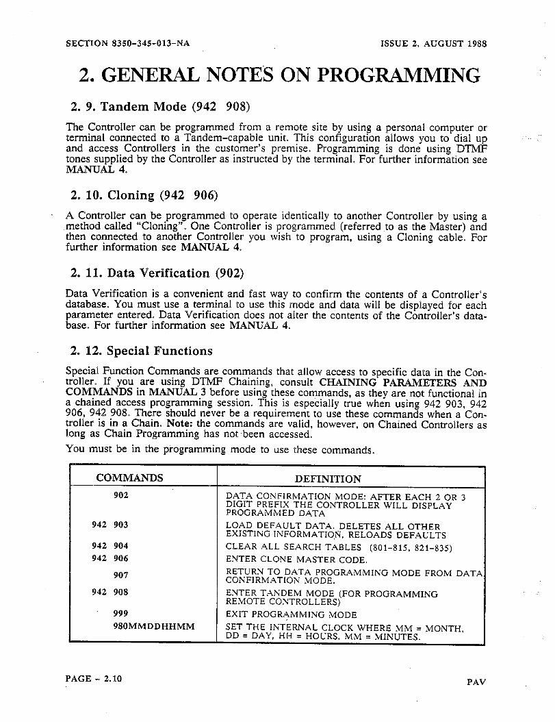
2. GENERAL NOTES ON PROGRAMMING 2. 9. Tandem Mode (942 908)
The Controller can be programmed from a remote site by using a personal computer or terminal connected to a Tandem-capable unit. This configuration allows you to dial up and access Controllers in the customer’s premise. Programming is done using DTMF tones supplied by the Controller as instructed by the terminal. For further information see MANUAL 4.
2. 10. Cloning (942 906)
. A Controller can be programmed to operate identically to another Controller by using a method called ‘“Cloning”. One Controller is programmed (referred to as the Master) and then connected to another Controller you wish to program, using a Cloning cable. For further information see MANUAL 4.
2. 11. Data Verification (902)
Data Verification is a convenient and fast way to confirm the contents of a Controllers database. You must use a terminal to use this mode and data will be displayed for each parameter entered. Data Verification does not alter the contents of the Controller’s data- base. For further information see MANUAE 4.
2. 12. Special Functions
Special Function Commands are commands that allow access to specific data in the Con- troller. If you are using DTMF Chaining, consult CHAINING PAIWVIETERS AND COMMANDS in MANUAL 3 before using these commands, as they are not functional in a chained access programming session. This is especially true when using 942 903, 942 906, 942 908. There should never be a requirement to use these commands when a Con- troller is in a Chain. Note: the commands are valid, however, on Chained Controllers as long as Chain Programming has not.been accessed. You must be in the programming mode to use these commands.
COMMANDS DEFINITION
902 DATA CONFIRMATION MODE: AFTER EACH 2 OR 3 DIGIT PREFIX THE CONTROLLER WILL DISPLAY PROGRAMMED DATA
942 903 LOAD DEFAULT DATA. DELETES ALL OTHER EXISTING INFORMATION, RELOADS DEFAULTS
942 904 CLEAR ALL SEARCH TABLES (801-815, 821-835) 942 906 ENTER CLONE iMASTER CODE.
907 RETURN TO DATA PROGRAMMING MODE FROM DATP CONFIRMATION M[ODE.
942 908 ENTER TANDEM MODE (FOR PROGRAMMING REMOTE CONTROLLERS)
999 EXIT PROGRAMMING MODE
980MMDDHHMM SET THE INTERNAL CLOCK WHERE MM = MONTH, DD = DAY, HH = HOURS, MM = MINUTES.
PAGE - 2.110 PAV

ISSUE 2, AUGUST 1988 SECTION 8350-345-013~NA
L
2. GENERAL NOTES ON PROGRAMMING Figure 2.1 Programming The Controller
000 - 015 SYSTEM WIDE OPTIONS
LINE/TRUNK OPTIONS C.O. TYPE, TIMING, ETC.
50X - 53X = ALL LINES
LINE 1 LINE 2 LINE 3 LINE 4
. 10x 20x 30x 40x
1’3”x 2Tpx 3Tfox qT1ox ALL 50 X TO 53X
-l--L DISABLED PASS ALL DISABLED
DIGITS DIRECTLY M 9 HOTLINE DEFAULT THROUGH ROUTE
PRIMARY SEARCH TABLES
SPEED CALL 700-799
PRIMARY ROUTES 55X = ALL ROUTES w SECONDARY ROUTES
57X = ALL ROUTES
15x 25x 35x 45x 17x 27X 37x ROUTE ROUTE ROWE
47x ROUTE ROUTE ROUTE ROUTE ROUTE
1 2 3 4 1 2 3 4
PRIMARY ROUTES 610 -645 I
ALTERNATE ROUTES 650 -685
-’
610
613 1 623 1 633 1
t t t t DDD 1ST 2ND 3RD
occ occ occ =F= DDD 1ST 2ND 3RD
occ occ occ
0 1 2 3-4 5 6 7
Warning: When programming Dial Plan/Search T’emplates, care should be taken to not affect calls that are dialed for emergency, e:g. 911 calls. After programming a Controller, check that the operation of emergency dialing has not been adversely affected.
PAV PAGE - 2.11

SECTION 8350-345013-NA ISSUE 2, AUGUST 1988
3. SELECTING THE CONTROLLER TYPE 3. 1. Specifying the Unit As A Call Controll& Or A PAV Controller
As it defaults to a regular Controller when initialized, you must specify the Controller as a PAV Controller if you wish to use it as. a Positive Account Code Verifier. This can be done by setting 011 to 1 as shown below:
REGISTER 011” I DESCRIPTION 1 DEFAUL’I
ENTER OllT T = 0 FOR REGULAR CONTROLLER OPERATION
T = 1 FOR PAV CONTROLLER
0
PAGE - 2.12 PAV

ISSUE 2, AUGUST 1988 SECTION 8350-345013-NA
REGISTER 000 DESCRIF’TION DEFAULT
ENTER OOOT T = 1 FOR 100 SPEED CALLS MAXIMUM 1 T = 2 FOR 1000 SPEED CALLS MAXIMUM
4. SYSTEM WIDE DATA 4. 1. General
You may want to change System Wide Data, because the default data does not meet your requirements. For example, all telephone lines are specified as loop start when default data is loaded. If you are using ground start lines, this must be changed. There is a series of Charts in APPENDIX 2 that will aid you in recordihg the information that you enter.
4. 2. Programming Speed Calls Speed Calls apply on a SYSTEM wide basis, but access can be restricted. There is a SPEED CALL Chart in APPENDIX 2 that will aid you in recording the speed calls used and the numbers assigned to them.
4. 3. Defining The Maximum Number Of Speed Calls You can define the maximum number of Speed Call-s by:
Note: An additional programming change will be necessary if you selected 2 for 1,000 Speed Calls, if the Speed Call trigger is to be recognized by the Primary Search Table and acted on.
1. The information in the 803 register (*#9#9#2) must be deleted by entering 803 *#9#9#9.
2. A new value must be added to the 804 register as 804 *#9#9#9#2. 3. This changes the Speed Call trigger range from *NN to *NNN. The * can be
a different digit if required.
4. 4. Setting up a Speed Call Method 1 Speed Call can be programmed in one of two ways. The first is generally done at the time of installation programming and has the following format:
P IS THE ACCOUNT CODE
7NN(N)DKMM...MM J~=P...PP##
, I
T -r -f ## INDICATES END OF ENTRY
* INDICATES THAT THE NEXT ENTRY BEGINS AN ACCOUNT CODE
MM IS THE PHONE NUMBER
K INDICATES HOW ROUTING WILL BE ACCOMPLISHED
D INDICATES WHICH TRUNK(S) IS TO BE ALLOWED ACCESS
’ ‘INN(N) IS THE SPEED CALL NUMBER LOCATTON
PAV PAGE - 2.13

SECTION 8350-345OP3-NA ISSUE 2, AUGUST 1988
4. SYSTEM WIDE DATA When you programmed OOOT (see page 2.13), you selected either 100 or 1000 speed calls available. To program a speed call use one of the formats in the following Chart:
REGISTER (FORMAT) DEFINITION
FOR 100 SPEED CALLS FORMAT FOR UP TO 100 ENTRIES. 7NNDKh4M...MM## NN IS THE SERVICE CODE TO BE DIALED BY
OR THE SUBSCRIBER AND MM...MM IS THE
7NNDKMM.. MM * P. .PP## NUMBER TO WHICH THE CODE IS TRANSLATED
FOR 1000 SPEED CALLS FORMAT’FOR UP TO 1000 ENTRIES. 7NNNDKMh&..MM## NNN IS THE SERVICE CODE TO BE DIALED BY
OR THE SUBSCRIBER AND MM...MM IS THE 7NNNDKMM...MM* P..PP## NUMBER TO WHICH THE CODE IS TRANSLATED
D is the key that selects the lines to access the call number
MUST BE ENTERED FROM A TERMINAL
K specifies how routing will be accomplished 0 - 7 Force on Route 0 7. 7 8 Use the screening table to determine routing 9 Dial immediate. no Route # (transoarent)
PP is an Account Code and is se the * . The +c and the Account c?
arated from the destination number by ode are optional.
Enters the information into memory
Speed Call Programming Example 1: Since the screen 803 *#9#9#2 already exists by default, up to 100 Speed Calls with the X&N format can be programmed:
Enter 722 085551818## will cause 555-1818 to be dialed out whenever a user dials *22.
Speed Call Programming Example 2: To program 411 calls to go to l-555-1212 you must set OOOT to 0002. Then:
Enter 803 411 #2##, sets 411 as a Speed Call trigger digit. Enter 7411 08 15551212## enters the Speed Call digit.
The unit is now set to dial out l-555-1212 whenever 411 is dialed into any trunk.
PAGE - 2.14 PAV
-.
ISSUE 2, AUGUST 1988 SECTION 8350-345-013-NA
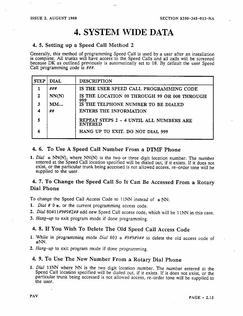
4. SYSTEM WIDE DATA 4. 5. Setting up a Speed Call Method 2
Generally, this method of programming Speed Call is used by a user after an installation is complete. All trunks will have access to the Speed Calls and all calls will be screened because DK as outlined previously is automatically set to 08. By default the user Speed Call programming code is ###.
STEP DIAL DESCRIPTION
###
NN(N) MM... ##
IS THE USER SPEED CALL PROGRAMMING CODE
IS THE LOCATION 00 THROUGH 99 OR 000 THROUGH 999 IS THE TELPHONE NUMBER TO BE DIALED ENTERS THE INFORMATION
pgAEPE;TEPS 2 - 4 UNTIL ALL NUMBERS ARE
HANG UP TO EXIT. DO NOT DIAL 999
4. 6. To Use A Speed Call Number From a DTMF Phone 1. Dial * NIT(N), where NN(N) is the two or three digit location number. The number
entered at the Speed Call location specified will be dialed out, if it exists. If it does not exist, or the particular trunk being accessed is not allowed access, re-order tone will be supplied to the user.
4. ‘7. To Change the Speed Call So It Can Be Accessed From a Rotary Dial Phone
To change the Speed Call Access Code to 1lNN instead of * NN: I. Dial # 0 *, or the current programming access code. 2. Dial 80411#9#9#2## add new Speed Call access code, which will be 1lNN in this case. 3. Hang-up to exit program mode if done programming.
4. 8. If You Wish To Delete The Old Speed Call Access Code I. While in programming mode Dial 803 e #9#9#9## to delete the old access code of
*N-N. 2. Hang-up to exit program mode if done programming.
4. 9. To Use The New Number From a Rotary Dial Phone 1. Dial 1lNN where NN is the two digit location number. The number entered at the
Speed Call location specified will be dialed out, if it exists. If it does not exist, or the particular trunk being accessed is not allowed access, re-order tone will be supplied to the user.
PAV PAGE - 2.15
SECTION 8350-345-013-NA ISSUE 2, AUGUST 1988
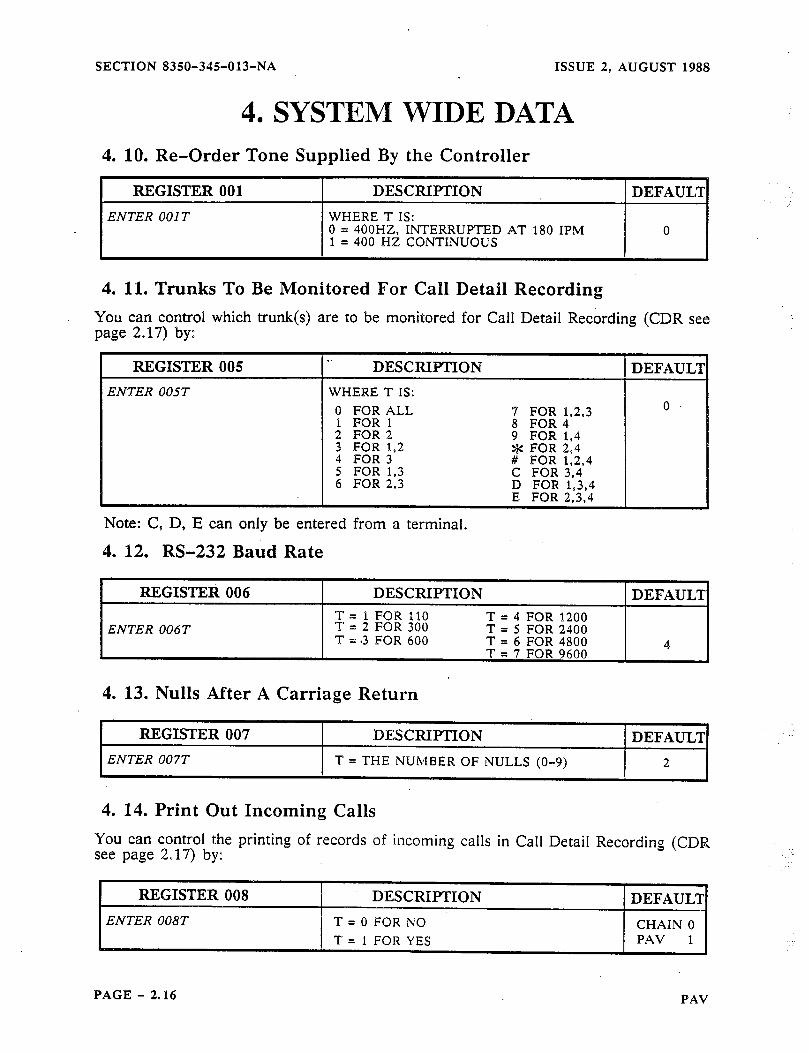
4. SYSTEM WIDE DATA 4. 10. Re-Order Tone Supplied By the Controller
REGISTER 001 DESCRIPTION DEFAUL’I
ENTER 001 T WHERE T IS: 0 = 400HZ, INTERRUPTED AT 180 IPM 0 1 = 400 HZ CONTINUOUS
: :
4. 11. Trunks To Be Monitored Por Call Detail Recording You can control which trunk(s) are to be monitored for Call Detail Recording (CDR see page 2.17) by:
ENTER 005T WHERE T IS:
Note: C, D, E can only be entered from a terminal.
4. 12. RS-232 Baud Rate
REGISTEfi 006 DESCRIPTION DEFAULT T = 1 FOR 110 T = 4 FOR 1200
ENTER 006T T = 2 FOR 300 T = 5 FOR 2400 T = .3 FOR 600 T = 6 FOR 4800 A
4. 13. Nulls After A Carriage Return
REGISTER 007 DESCRI[PTION DEFAULT
ENTER 007T T = THE NUMBER OF NULLS (O-9) 2
4. 14. Print Out Incoming Calls You can control the printing of records of incoming calls in Call Detail Recording (CDR see page 2.17) by:
PAGE - 2.16 PAV
ISSUE 2, AUGUST 1988
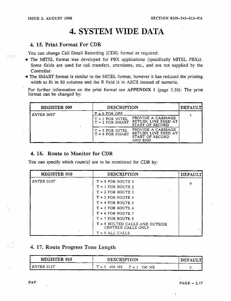
4. SYSTEM 4. 15. Print Format For CDR
SECTION 8350-345-013-NA
WIDE DATA
You can change Call Detail Recording (CDR) format as required:
l The MIIEL format was developed for PBX applications (specifically MlTEL PBXs). Some fields are used for call transfers, attendants, etc., and are not supplied by the Controller.
l The SMART format is similar to the MlTEL format, however it has reduced the printing width to fit in 80 columns and the R field is in ASCII instead of numeric.
For further information on the print format see APPENDIX 1 (page 2.50). The print format can be changed by:
REGISTER 009 DESCRIPTION. DEFAUL’Z
ENTER 009T T = 0 FOR OFF 1 T = 1 FOR ,&fITEL PROVIDE A CARRIAGE T = 2 FOR SMART RETURN LINE FEED AT
START OF RECORD T = 5 FOR M[TEL PROVIDE A CARRIAGE T = 6 FOR S,MART RETURN LINE FEED AT
START OF RECORD AND END
4. 16. Route to Monitor
You can specify which route(s)
for CDR
are to be monitored for CDR by:
REGISTER 010
ENTER OIOT
DESCRIPTION
T = 0 FOR ROUTE 1
T = 1 FOR ROUTE 2 T = 2 FOR ROUTE 3 T = 3 FOR ROUTE 4
T = 1 FOR ROUTE 5 T = 5 FOR ROUTE 6 T = 6 FOR ROUTE 7 T = 7 FOR ROUTE 8
T = 8 ROUTED CALLS AND OUTSIDE CENTREX CALLS ONLY
T = 9 ALL CALLS
4. 17. Route Progress Tone Length
DEl?AUL?
9
REGISTER 015 I DESCRIPTION
ENTER 015T t T = 0 JO0 MS T = 1 100 MS
DEFAUL’I
n
PAV PAGE - 2.17

SECTION 8350-345-013-NA ISSUE 2, AUGUST 1988
5. LINE AND TRUNK OPTIONS
5. 1. General When programming line and trunk options you should remember Trunk 1 is not related to Route 1, or Trunk 2 is not related to Route 2, etc. _.: ., ..-
Line and Trunk refer to the physical line that is supplied by your telephone company. Route refers to the way the Controller will attempt to route the call through the Public Switched Telephone Network.
For example: l-800 numbers may be routed on Route 0, while a l-201 is routed to a common carrier via Route 1. Any trunk may access any Route depending on how you program the Controller.
All entries in this part are of a predetermined length. When you have entered the correct number of digits, the Controller will automatically accept the entry (informing as to the correctness as outlined on page 2.7).
5. 2. Type Of Dialing And Trunk You can specify the type of trunk as loop or ground start, and the type of dialing as BTMP or rotary by:
REGISTER X00
ENTER I FOR LINE 1 + OOT ENTER 2 FOR LINE 2 + OOT
ENTER 3 FOR LINE 3 + OOT ENTER 4 FOR LINE 4 + OOT
ENTER 5 FOR ALL + OOT
5. 3. Rotary Dialing Rates
REGISTER XOP
ENTER I FOR LINE 1 + OlT ENTER 2 FOR LINE 2 + OlT
ENTER 3 FOR LINE 3 + OlT
ENTER 4 FOR LINE 4 + OlT ENTER 5 FOR ALL + OlT
DESCRIPTION DEFAULT T = 0 FOR LOOP START, ROTARY T = 1 GROUND START, ROTARY 2 T = 2 FOR LOOP START, DTMF T = 3 FOR GROUND START. DTMF
DESCRIPTION 1 DEFAULI T = 2 FOR OUTPULSE AT 30120 MS 20 PPS
WHICH EQUATES TO 60% BREAK 4
T = 4 FOR OUTPULSE AT 60140 MS 10 PPS WHICH EQUATES TO 60% BREAK
I
.
.-. .__
PAGE - 2.18 PAV

ISSUE 2, AUGUST 1988
5. LINE AND TRUNK 5. 4. DTMF Dialing Rates
SECTION 8350-345-013-NA
OPTIONS
RJZGISTER X02 ENTER 1 FOR LINE 1 + 02T ENTER 2 FOR LINE 2 + 02T
ENTER 3 FOR LINE 3 + 02T
ENTER 4 FOR LINE 4 + 02T ENTER 5 FOR ALL + 02T
DESCRIPTION DEFAULT
T = ; $ lMi(fast)
1 :MS T 2 60 T=3 70MS T = 4 80 MS. T = 5 90 MS
T = 6 100 MS .T = 7 110 MS T = 8 120 MS T = 9 130 MS(slow)
1
5. 5, On Hook Time You can specify the on-hook recognition time by:
REGISTER X03 DESCRIPTION DEFAUL’I:
ENTER 1 FOR LINE 1 + 03T T = 0 FOR 80 MS T = 6 FOR 750 MS
ENTER.2 FOR LINE 2 + 03T T = 1 FOR 100 IMS T = 7 FOR 1000 MS 6 T = 2 FOR 150 MS T = 8 FOR 1330 MS
ENTER 3 FOR LINE 3 + 03T T = 3 FOR 200 MS T = 9 FOR 1660 MS
ENTER 4 FOR LINE 4 + 03T T = 4 FOR 300 MS T = * FOR 2 S T = 5 FOR 500 MS T = # FOR 2.5s
ENTER 5 FOR ALL + 03T
Note: There is a relationship between X03 and X04 (see page 2.20). If X03 is less than X04, all switch-hook flashes will be recognized as on-hooks as outlined below:
0 TIME INTERVALS *
FLASH TIME ON-HOOK TIME AS SET BY AS SET BY
X04T X03T
IF THE FLASH TIME IS SET TO MORE THAN THE ON-HOOK TIME
THE FLASH IS NOT ALLOWED
PAV PAGE - 2.19
SECTION 8350-34%013-NA
5. LINE
ISSUE 2, AUGUST 1988
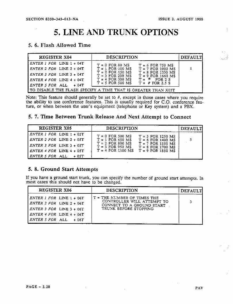
AND TRUNK OPTIONS 5. 6. Flash Allowed Time
1 REGISTER X04 DESCRIPTION I DEFAULT ENTER I FOR LINE 1 + 04T ENTER 2 FOR LINE 2 + 04T
ENTER 3 FOR LINE 3 + 04T
ENTER 4 FOR LINE 4 + 04T
ENTER 5 FOR ALL
+04T 1 gg$J) ~igjJ/j:
TO DISABLE THE FLASH SPECIFY A TIME THAT IS GREATER THAN XO?T
Note: This feature should generally be set to #, except in those cases where you require the ability to use conference features. This is usually required for C.O. conference fea- ture, or when betweebn the user’s equipment (telephone or Key system) and a PBX.
5, ‘7. Time Between Trunk Release And Next Attempt to Connect
ENTER ! FOR LINE 1 + 05T T = 0 FOR 500 MS T = 5 FOR 1250 MS ENTER 2 FOR LINE 2 + 05T T = 1 FOR 650 MS T = 6 FOR 1400 MS ENTER 3 FOR LINE 3 + 05T T = 2 FOR 800 MS T = 7 FOR 1550 MS
T = 3 FOR 950 MS T = 8 FOR 1400 MS ENTER 4 FOR LINE 4 + 05T T = 4 FOR IL100 MS T = 9 FOR 1850 MS
ENTER 5 FOR ALL
5. 8. Ground Start Attempts If you have a ground start trunlc, you can specify the number of ground start attempts. In most cases this should not have to be changed.
REGISTER X06
ENTER % FOR LINE 1 + 06T ENTER 2 FOR LINE 2 + 06T
ENTER 3 FOR LINE 3 + 06T
ENTER 4 FOR LINE 4 + 06T ENTER 5 FOR ALL + 06T
DESCRIITION
T = THE NUMBER OF TIMES THE CONTROLLER WILL ATTEMPT TO CONNECT TO A GROUND START TRUNK BEFORE STOPPING
DEFAUL’I
PAGE - 2.20 PAV
ISSUE 2, AUGUST 1988 SECTION 8350-345-013-NA
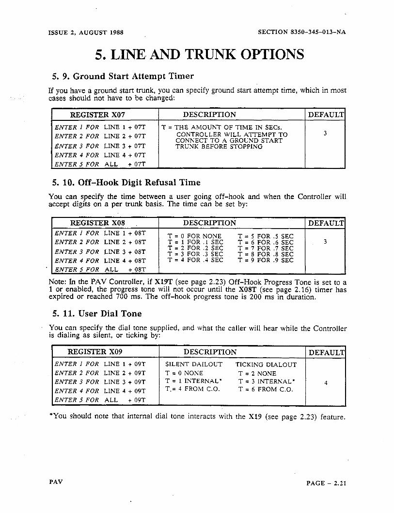
5. LINE. AND TRUNK- OPTIONS 5. 9. Ground Start Attempt Timer
If you have a ground start trunk, you can specify ground start attempt time, which in most cases should not have to be changed:
REGISTER X07 DESCRIPTION DEFAULI
ENTER 1 FOR LINE 1 + 07T T = THE AMOUNT OF TIME IN SECs. ENTER 2 FOR LINE 2 + 07T CONTROLLER WILL ATTEMPT TO 3
CONNECT TO A GROUND START ENTER 3 FOR LINE 3 + 07T TRUNK BEFORE STOPPING ENTER 4 FOR LINE 4 + 07T
ENTER 5 FOR ALL + 07T
5. 10. Off-Hook Digit Refusal Time You can specify the time between a user going off-hook and when the Controller will accept digits on a per trunk basis. The time can be set by:
REGISTER X08 . DESCRIPTION DEFAULT ENTER 1 FOR LINE 1 + 08T T = 0 FOR NONE T = 5 FOR .5 SEC ENTER 2 FOR LINE 2 + 08T T = 1 FOR .I SEC T = 6 FOR .6 SEC 3
ENTER 3 FOR LINE 3 + 08T T = 2 FOR .2 SEC T = 7 FOR .7 SEC T = 3 FOR .3 SEC T = 8 FOR .8 SEC
ENTER 4 FOR LINE 4 + 08T T = 4 FOR .4 SEC T = 9 FOR .9 SEC
- ENTER 5 FOR ALL + OBT
Note: In the PAV Controller, if X19T (see page 2.23) Off-Hook Progress Tone is set to a 1 or enabled, the progress tone will not occur until the X08T (see page 2.16) timer has expired or reached 700 ms. The off-hook progress tone is 200 ms in duration.
5. 11. User Dial Tone You can specify the dial tone supplied, and what the caller will hear while the Controller is dialing as silent, or ticking by:
REGISTER X09 DESCRIPTION DEFAULT I
ENTER 1 FOR LINE 1 + 09T SILENT DAILOUT TICKING DIALOUT ENTER 2 FOR LINE 2 + 09T T = 0 NONE T = 2 NONE ENTER 3 FOR LINE 3 + 09T T = 1 INTERNAL* T = 3 INTERNAL* 4 ENTER 4 FOR LINE 4 + 09T T.= 4 FROM C.O. T = 6 FROM C.O.
ENTER 5 FOR ALL + 09T
*You should note that internal dial tone interacts with the X19 (see page 2.23) feature.
PAV PAGE - 2.21
SECTION 8350-345-013-NA ISSUE 2, AUGUST 1988
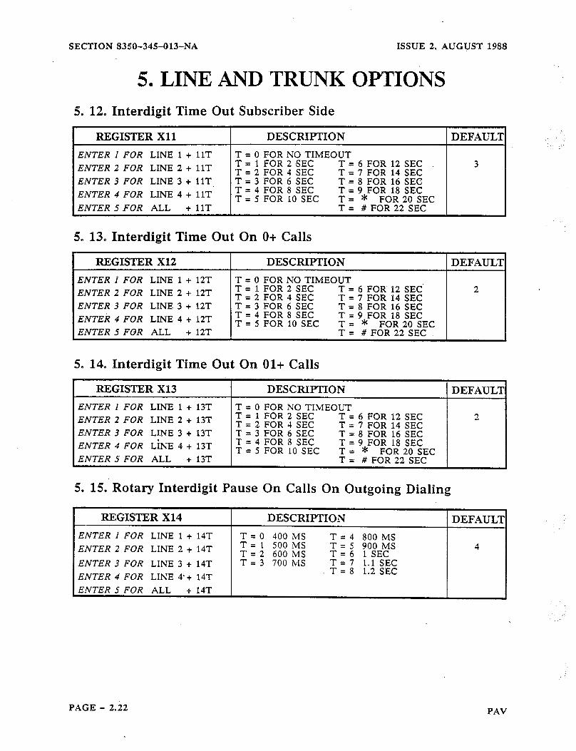
5. LINE AND TRUNK OPTIONS 5. 12. Interdigit Time Out Subscriber Side
I REGISTER Xl 1 DESCRIPTION ( DEFAULS
ENTER I FOR LINE 1 + flT
ENTER 2 FOR LINE 2 + 11T
ENTER 3 FOR LINE 3 + 11T
ENTER 4 FOR LINE 4 + 1lT
ENTER 5 FOR ALL + 1fT
T = 0 FOR NO TIMEOUT T = 1 FOR 2 SEC T = 6 FOR 12 SEC T = 2 FOR 4 SEC T = 7 FOR 14 SEC T = 3 FOR 6 SEC T = 8 FOR 16 SEC T = 4 FOR 8 SEC T = 9 FOR 18 SEC T = 5 FOR 10 SEC : = * FOR 20 SEC
= # FOR 22 SEC
3
5, 13. Interdigit Time Out On O+ Calls
REGISTER X12
ENTER 1 FOR LINE 1 + 12T ENTER 2 FOR LINE 2 + %%T
ENTER 3 FOR LINE 3 += l2T
ENTEk 4 FOR LINE 4 + f2T ENTER 5 FOR ALL + 12T
I DESCRIPTION
T = 0 FOR NO TIMEOUT T = 1 FOR 2 SEC T = 6 FOR 12 SEC T = 2 FOR 4 SEC T = 7 FOR 14 SEC T = 3 FOR 6 SEC T = 8 FOR 16 SEC T = 4 FOR 8 SEC T = 9 FOR 18 SEC T = 5 FOR 10 SEC : = * FOR 20 SEC
= # FOR 22 SEC
DEFAUL1
2
5. 14. Interdigit Time Out On Ol+ Calls
REGISTER Xl3 DESCRIPTION
ENTER % FOR LINE 1 + 13T T = 0 FOR NO TIMEOUT ENTER 2 FOR LINE 2 = + 13T T 1 FOR 2 SEC T = 6 FOR 12 SEC
T = 2 FOR 4 SEC T = 7 FOR 14 SEC ENTER 3 FOR LINE 3 + l3T T = 3 FOR 6 SEC T = 8 FOR 16 SEC ENTER 4 FOR LiNE 4 + l3T T = 4 FOR 8 SEC T = 9 FOR 18 SEC
T = 5 FOR 10 SEC = * FOR 20 SEC ENTER 5 FOR ALL + 13T ; = # FOR 22 SEC
5. 15. Rotary Interdigit Pause On Calls On Outgoing Dialing
REGISTER Xl4
ENTER 1 FOR LINE 1 + 14T
ENTER 2 FOR LINE 2 + 14T
ENTER 3 FOR LINE 3 + 14T
ENTER 4 FOR LINE 4’+ 14T
ENTER 5 FOR ALL + 14T
DESCRIPTION
T = 0 400 MS T = 4 800 MS T = 1 500 MS T = 2 600 MS
T r -
2 ~O$o#
T = 3 700 hii T = 7 1.1 S&Z T = 8 1.2 SEC
DEFAULT
DEFAUL’J
4
PAGE - 2.22 PAV
ISSUE 2, AUGUST 1988 SECTION 8356345-613-NA
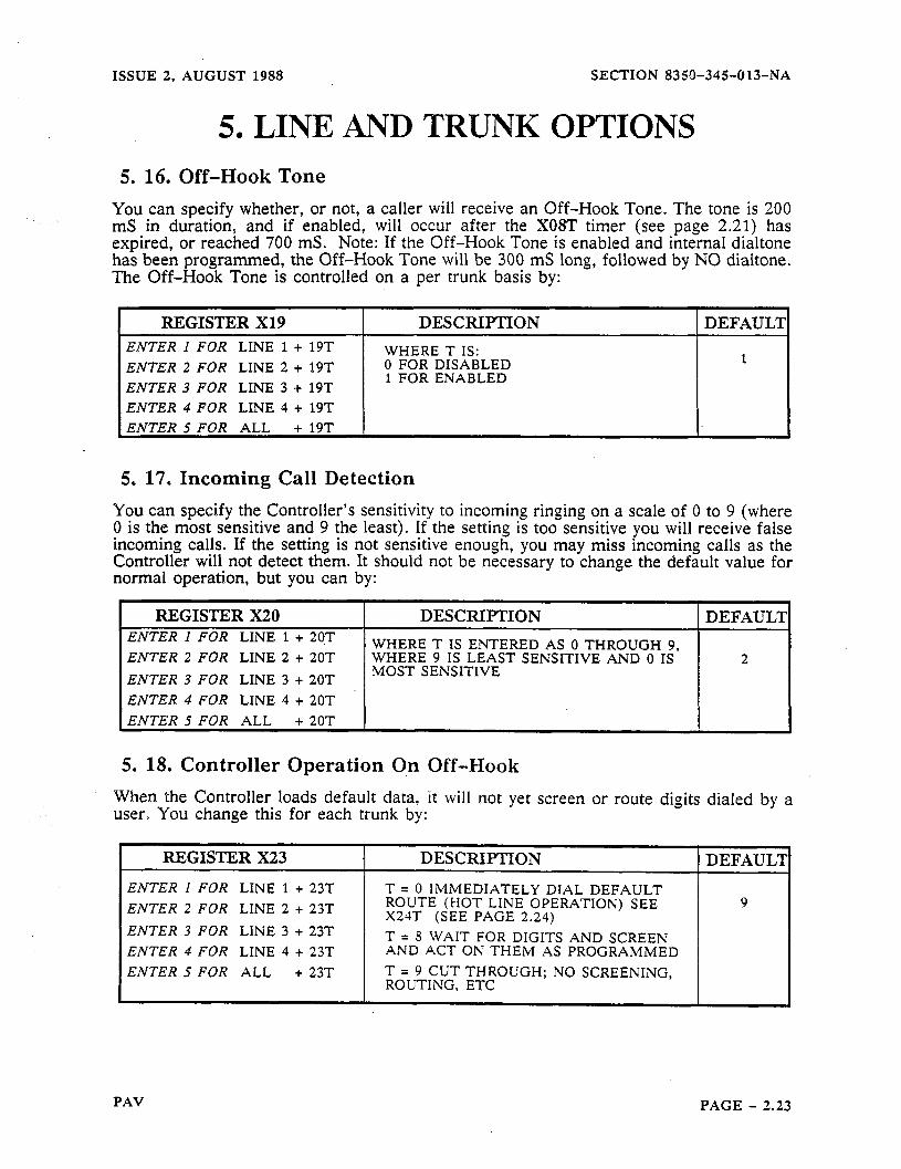
5. LINE AND TRUNK OPTIONS 5. 16. Off-Hook Tone
You can specify whether, or not, a caller will receive an Off-Hook Tone. The tone is 200 mS in duration, and if enabled, will occur after the XOST timer (see page 2.21) has expired, or reached 700 mS. Note: If the Off-Hook Tone is enabled and internal dialtone has been programmed, the Off-Hook Tone will be 300 mS long, followed by NO dialtone. The Off-Hook Tone is controlled on a per trunk basis by:
I REGISTER X19 I DESCRIPTION I DEFAULl ENTER I FOR LINE 1 + 19T WHERE T IS: ENTER 2 FOR LINE 2 + 19T 0 FOR DISABLED
ENTER 3 FOR LINE 3 t 19T 1 FOR ENABLED
ENTER 4 FOR LINE 4 + 19T ENTER t7 FOR ALL + 49T
5. 17, Incoming Call Detection You can specify the Controller’s’sensitivity to incoming ringing on a scale of 0 to 9 (where 0 is the most sensitive and 9 the least). If the setting is too sensitive you will receive false incoming calls. If the setting is not sensitive enough, you may miss incoming calls as the Controller will not detect them. It should not be necessary to change the default value for normal operation, but you can by:
REGISTER X20 I DESCRIPTION ENTER 1 F-OR LINE 1 + 20T WHERE T IS ENTERED AS 0 THROUGH 9. ENTER 2 FOR LINE 2 + 20T WHERE 9 IS LEAST SENSITIVE AND 0 IS
ENTER 3 FOR LINE 3 + 20T MOST SENSITIVE
ENTER 4 FOR LINE 4 + 20T ENTER 5 FOR ALL + 20T I
DEFAULT
2
5. 18. Controller Operation 0,n Off-Hook When the Controller loads default data, it will not yet screen or route digits dialed by a user. You change this for each trunk by:
REGISTER X23
ENTER I FOR LINE 1 t 23T
ENTER 2 FOR LINE 2 t 23T
ENTER 3 FOR LINE 3 t 23T
ENTER 4 FOR LINE 4 t 23T
ENTER S FOR ALL t 23T
DESCRIPTION 1 DEFAUL’I
T = 0 IMMEDIATELY DIAL DEFAULT ROUTE (HOT LINE OPERATION) SEE X24T (SEE PAGE 2.24)
T = 8 WAIT FOR DIGITS AND SCREEN AND ACT ON THEIM AS PROGRAMMED
T = 9 CUT THROUGH; NO SCREENING, ROUTING, ETC I
9
PAV PAGE - 2.23
ISSUE 2. AUGUST 1988 SECTION 83§@-345013-NA
5. LINE AND TRUNK OPTIONS 5. 19. Specify Default Route
You can specify a default route for a trunk (see also #8 Action Digit) by:
ENTER 2 FOR LINE 2 + 24T ENTER 3 FOR LINE 3 + 24T
ENTER 4 FOR LINE 4 + 24T
$ For the Route specified here to be in effect, X23 (see page 2.23) must be set to X230 or a #8 (Action Digit) must occur in the Primary Search Table (after the number dialed has been matched). This will cause the Controller to use a specific Route. If a Route O-3 has been selected (through programming) all calls will be routed on the Primary Route. If a Route 4-7 has been selected (through programming) all calls will be routed on the Alter- nate Route.
5. 20. Specify The Digit For Centrex Access You can specify the digit to be used for outgoing centrex access. This usually occurs when the Controller is placed behind a Centrex or PBX unit and you are required to dial a digit - typically a 9 - to access the outside line. If the Controller detects a Centrex Access Digit. it will screen the remaining digits and process the call. If the Controller does not detect a Centrex Access Digit it will not screen and just dial.
REGISTER X25 DESCRIPTION DEFAULT ENTER I FOR LINE 1 + 25T WHERE T IS THE CENTREX DIGIT. ENTER 2 FOR LINE 2 + 25T IF X26T = X261 (BELOW) THEN ALL INTRA 9
CENTREX CALLS ARE DIALED .
ENTER 3 FOR LINE 3 + 25T IMMEDIATELY ENTER 4 FOR LINE 4 =+ 25T
ENTER 5 FOR ALL + 25T
5. 21. Centrex Enable/Disable You can enable or disable the Centrex by:
REGISTER X26
ENTER I FOR LINE 1 + 26T
ENTER 2 FOR LINE 2 + 26T
ENTER 3 FOR LINE 3 + 26T ENTER 4 FOR LINE 4 + 26T ENTER 5 FOR ALL + 26T
DESCRIPTION DEFAULT WHERE T IS: 0 FOR DISABLE 1 FOR ENABLE
0
PAGE - 2.24 PAV

ISSUE 2, AUGUST 1988
5. LINE AND 5. 22. Time To Auto-Answer
You can specify the time the Controller detection of ringing by:
SECTION 8350-345-013-NA
TRUNK OPTIONS
waits before answering an incoming call after the
REGISTER X27 DESCRIPTION DEFAULT ENTER I FOR LINE 1 t 27T T = 0 FOR DISABLE
ENTER 2 FOR LINE 2 t 27T T = 1 FOR 10 S T = 6 FOR 60 S 0 T = 2 FOR 20 S T = 7 FOR 70 S
ENTER 3 FOR LINE 3 t 27T T = 3 FOR 30 S T = 8 FOR 80 S
ENTER 4 FOR LINE 4 t 27T T = 4 FOR 40 S T = 9 FOR 90 S T = 5 FOR 50 S *FOR 100 S
A ENTER 5 FOR ALL t 27T : = # FOR 120 S
5. 23. Wait For Security Code Timer This parameter specifies the time in which a security code (603 Parameter see 7. 3. on page 2.33) must be entered on a trunk after the Controller auto-answers. If timeout oc- curs or an incorrect password is entered, the trunk will be locked as specified in the X29 parameter (next parameter discussed). The time to wait for password can be changed by:
REGISTER X28 DESCRIPTION DEFAULT ENTER 1 FOR LINE 1 t 28T T = 0 FOR DISABLE
ENTER 2 FOR LINE 2 t 28T T = 1 FOR 10 S T = 6 FOR 60 S 6 T = 2 FOR 20 S T = 7 FOR 70 S
ENTER 3 FOR LINE 3 t 28T T = 3 FOR 30 S T = 8 FOR 80 S
ENTER 4 FOR LINE 4 t 28T T = 4 FOR 40 S T = 9 FOR 90 S T = 5 FOR 50 S *FOR 100 S
ENTER 5 FOR ALL + 28T : I# FOR 120 S
5. 24. Incorrect/Failed Security Code Trunk Lockout Timer Failure to enter the correct programming password during the time specified by the X28 parameter enables this timer. You can specify the time a trunk is locked out. If the timeout occurs, or an incorrect password is entered, the trunk will be locked out’as speci- fied, or until on the user side of the line goes off-hook. The time for password can be changed by:
REGISTER X29 DESCRIPTION DEFAUL’I ENTER 1 FOR LINE 1 t 29T T = 0 FOR DISABLE ENTER 2 FOR LINE 2 t 29T T = 1 FOR 10 S T = 6 FOR 60 S 9
T = 2 FOR 20 S T = 7 FOR 70 S ENTER 3 FOR LINE 3 t 29T T = 3 FOR 30 S T = 8 FOR 80 S ENTER 4 FOR LINE 4 29T T = = t 4 FOR -10 S T 9 FOR 90 S
ENTER 5 FOR ALL T = 5 FOR 50 S T= *FORlOOS
t 29T T = # FOR 120 S
PAV PAGE - 2.25

SECTION 8350-345013-NA ISSUE 2, AUGUST 1988
5. LINE AND TRUNK OPTIONS 5. 25. Off-Hook Recognition Timer
I REGISTER X30 I DESCRIPTION I DEFAUL’I ENTER I FOR LINE 1 + 3OT ‘WHERE T IS: ENTER 2 FOR LINE 2 + 30T 0=20 MS - 4= 80 MS 8 = 160 MS 3
3 FOR LINE 3 30T 1 = 20 MS
ENTER = 100 MS 9 = 180 MS
+ 2 40 = MS 65=120MS *=2OOMS ENTER 4 FOR LINE 4 + 30T 3 = 60 IMS 7 = 140 MS # = 220 MS
ENTER 5 FOR ALL + 30T
5. 26. Tip Ground Application Recognition Timer
This command selects the time that a tip ground must be applied on a ground starttrunk, for that application to be recognized. If you are using a terminal you can substitute the letter A f6; the * and B for the #.
REGISTER X31 DESCRIFTXON DEFAULT
ENTER I FOR LINE 1 i- 31T T = 0 FOR 40 MS T = 6 FOR 240 MS ENTER 2 FOR LINE 2 + 31T T = 1 FOR 40 MS .T=7FOR280MS 3
T = 2 FOR 80 MS T = 8 FOR 320 MS ENTER 3 FOR LINE 3 -I= 3lT T = 3 FOR 120 MS T = 9 FOR 360 MS
= ENTER 4 FOR LINE 4 T 4 FOR 160 MS + 3lT T = 5 FOR 200 MS
: I# *FOR 400 MS FOR 440 MS
ENTER S FOR ALL + 3lT
5. 2’7* Digit Recognition On Outgoing Calls
R.EGISTER X32 I DESCRIPTION 1 DEFAULl ENTER I FOR LINE 1 -I- 32T ENTER 2 FOR LINE 2 -+ 32T
ENTER 3 FOR LINE 3 + 32T
ENTER 4 FOR LINE 4 + 32T
ENTER 5 FOR ALL + 32T
T = 0 FOR ALLOW DTMF, JO OR 20 PPS T = 1 IGNORE ALL ROTARY T = 2 IGNORE ALL DTMF T = 3 IGNORE ALL DIGITS T = 5 FOR GO TO REORDER ON ROTARY T = 6 FOR GO TO REORDER ON DTMF T = 7 FOR G.0 TO REORDER ANY DIGITS
0
PAGE - 2.26
_
PAV
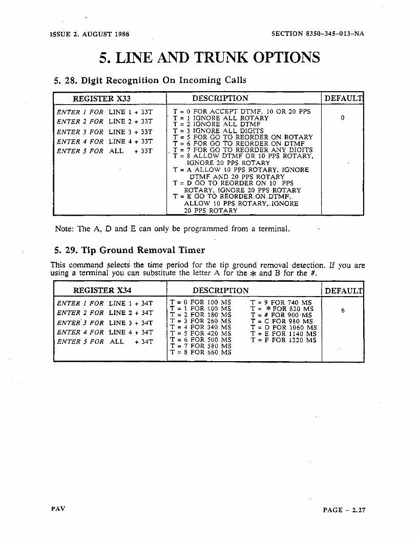
ISSUE 2. AUGUST 1988 SECTION 8350-345-013-NA
5. LINE AND TRUNK OPTIONS 5. 28. Digit Recognition On Incoming Calls
REGISTER X33 DESCRIPTION DEFAULT
ENTER I FOR LINti 1 + 33T T = 0 FOR ACCEPT DTMF, 10 OR 20 PPS
ENTER 2 FOR LINE 2 + 33T ’ T = 1 IGNORE ALL ROTARY 0 T = 2 IGNORE ALL DTMF
ENTER 3 FOR LINE 3 + 33T T = 3 IGNORE ALL DIGITS
ENTER 4 FOR LINE 4 + 33T T = 5 FOR GO TO REORDER ON ROTARY T = 6 FOR GO TO REORDER ON DTMF
ENTER 5 FOR ALL + 33T . T = 7 FOR GO TO REORDER ANY DIGITS T = 8 ALLOW DTMF OR 10 PPS ROTARY,
IGNORE ‘20 PPS ROTARY T = A ALLOW 10 PPS ROTARY, IGNORE
DTMF AND 20 PPS ROTARY T = D GO TO REORDER ON 10 PPS
ROTARY, IGNORE 20 PPS ROTARY T = E GO TO REORDER.ON.DTMF,
ALLOW 10 PPS ROTARY,..IGNORE 20 PPS ROTARY
Note: The A, D and E can only be programmed from a terminal. a
5. 29. Tip Ground Removal Timer
This command s&lects the time period for the tip ground removal detection. If you are using a terminal you can substitute the letter A for the * and B for the #.
REGISTER X34 I DESCRIF’TION 1 DEFAUL’J
ENTER 1 FOR LINE 1 + 34T T = 0 FOR 100 MS T = 9 FOR 740 MS = ENTER 2 FOR LINE 2 T 1 FOR 100 T= -I; 34T MS *FOR820MS
T = 2 FOR 180 MS T = 6
# FOR 900 .MS ENTER.3 FOR LINE 3 + 34T T = 3 FOR 260 MS T = C FOR 980 MS
T = 4 FOR 340 MS ENTER 4 FOR LINE 4 + 34T
T = D FOR 1060 MS T = 5 FOR -120 MS T = E FOR 1140 MS
ENTER 5 FOR ALL + 34T T = 6 FOR 500 IMS T = F FOR 1220 MS T = 7 FOR 580 MS T = 8 FOR 660 MS
PAV PAGE - 2.27
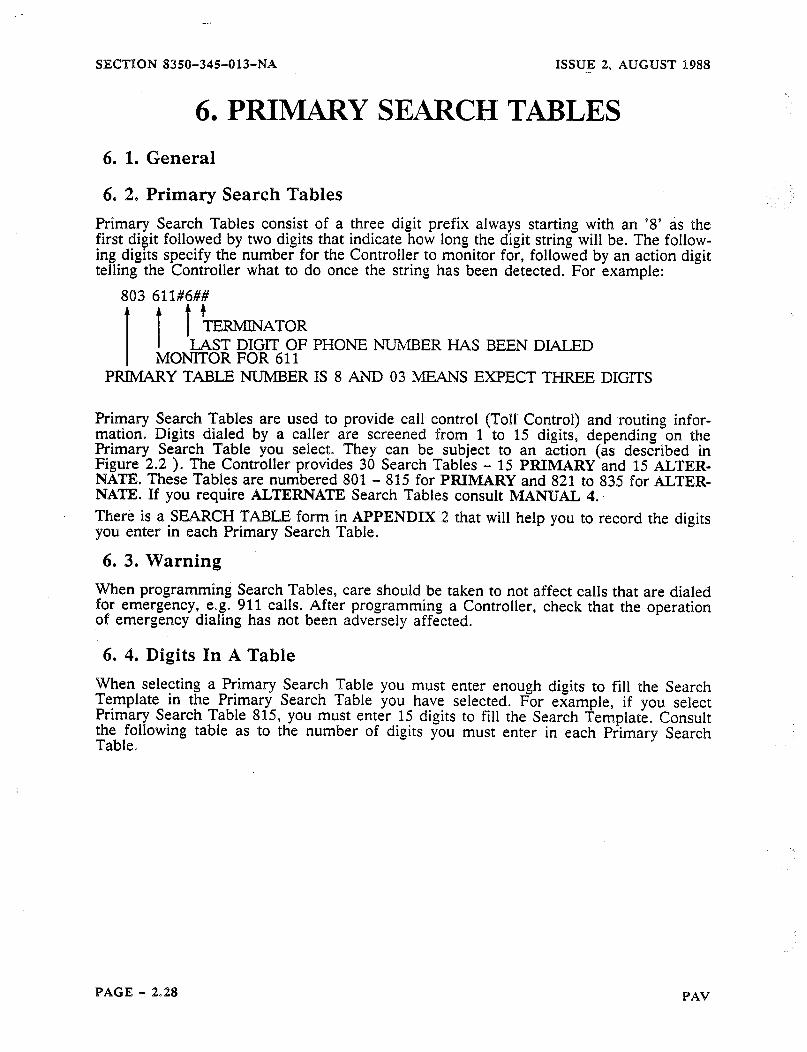
-..
SECTION 8350-34§-013-NA ISSUE 2, AUGUST 1988 -.
6. PRIMARY SEARCH TABLES
6. 1. General
6. 2. Primary Search Tables Primary Search Tables consist of a three digit prefix always starting with an ‘8’ as the first digit followed by two digits that indicate how long the digit string will be. The follow- ing digits soecifv the number for the Controller to monitor for. followed by an action digit tefiingthe aController what to do once the string has been detected. For example:
803 611#6##
1 1 / ?I-ERMIN*TOR
I I LAST DIGIT OF PHONE NUMBER HAS BEEN DL4LED MONITOR FOR 611
PRIMARY TABLE NUMBER IS 8 AND 03 MEANS EXPECT. THREE DIGITS
Primary Search Tables are used to provide call control (Toll. Control) and -routing infor- mation Digits dialed by a caller are screened from 1 to 15 digits, depending on the Primary Search Table you select. They can be subject to an action (as described in Figure 2.2 ). The Controller provides 30 Search Tables - 15 PRIMARY and 15 ALTER- NATE. These Tables are numbered 801 - 815 for PRIMARY and 821 to 835 for ALTER- NATE. If you require ALTERNATE Search Tables consult MANUAL 4.. There is a SUCH TABLE form in APPENDIX 2 that will help you to record the digits you enter in each Primary Search Table.
6. 3. Warning V&en programming Search Tables, care should be taken to not affect calls that are dialed for emergency, e.g. 911 calls. After programming a Controller, check that the operation of emergency dialing has not been adversely affected.
6. 4. Digits In A Table When selecting a Primary Search Table you must enter enough digits to fill the Search Template in the Primary Search Table you have selected. For example, if you select Primary Search Table 815, you must enter 15 digits to fill the Search Template. Consult the following table as to the number of digits you must enter in each Primary Search Table.
PAGE - 2.28 PAV
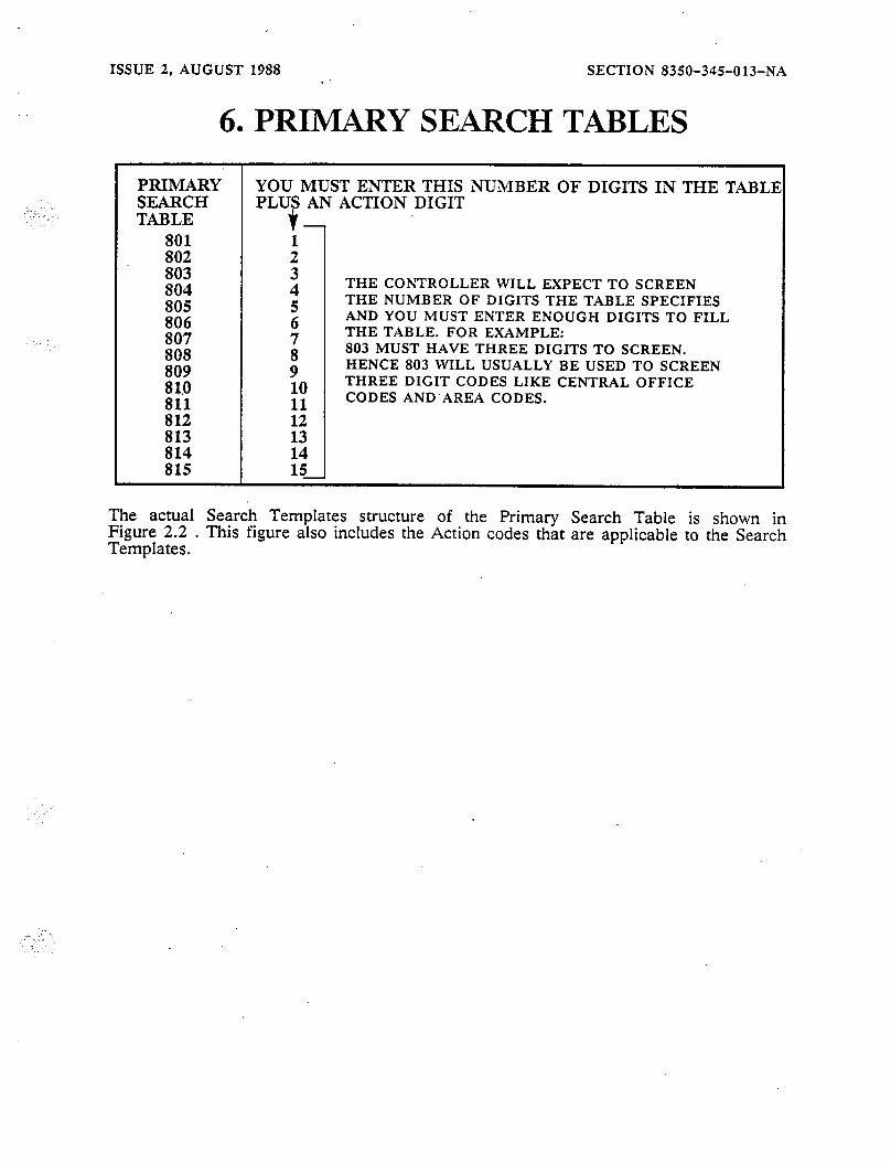
,,.,:-
ISSUE 2, AUGUST 1988 SECTION 8350-345-013-NA
6. PRIMARY SEARCH TABLES
PRIMARY’ YOU MUST ENTER THIS NUMBER OF DIGITS IN THE TABLI SEARCH PLUS AN ACTION DIGIT TABLE
THE CONTROLLER WILL EXPECT TO SCREEN THE NUMBER OF DIGITS THE TABLE SPECIFIES AND YOU MUST ENTER ENOUGH DIGITS TO FILL THE TABLE. FOR EXAMPLE: 803 MUST HAVE THREE DIGITS TO SCREEN. HENCE 803 WILL USUALLY BE USED TO SCREEN THREE DIGIT CODES LIKE CENTRAL OFFICE CODES AND AREA CODES.
The actual Search Templates structure of the Primary Search Table is shown in Figure 2.2 . This figure also includes the Action codes that are applicable to the Search Templates.
..-
PAV PAGE - 2.29

SECTION 835O-345013-NA ISSUE 2, AUGUST 1988
6. PRIMARY SEARCH TABLES Figure 2.2 Search Table Format and Action Codes
115 IS THE REGISTER NUMBER. WHERE THE 8 INDICATES A SEARCH TABLE TOLLOWING TWO DIGITS INDICATE THE NUMBER OF DIGITS TO BE SCREENED, IN THIS :ASE THE CONTROLLER SCREENS 15 DIGITS.
$NN ARE DIGITS YOU WANT THE CONTROLLER TO MATCH TO J MAY BE ANY DIGIT 0 - 9 AND * WHICH WILL BE MATCHED AGAINST THE DIGITS XALED BYTHE SUBSCRIBER. N CAN ALSO BE: #O COMPARE AGAINST A USER DIALED #
#I COMPARE AGAINST A USER DIALED 1 OR 0 #4 COMPARE AGAINST ANY USER DIALED DIGIT 2 - 9 #9 COMPARE AGAINST ANY USER DIALED DIGIT
i REPRESENTS THE ACTION DIGITS INSTRUCTING THE ACTION TO BE TAKEN WHEN A MATCH >R ENOUGH DIGTS HAS OCCURED. FURTHER INFORMATION SEE BELOW f# INDICATES THE END OF THE ENTRY
A ACTION CODE DIGITS
FER ROUTE #1 PREFER ROUTE #2 THE ROUTE SELECTED COULD BE CHANGED LATER ON PREFER ROUTE #3 IN THE DIALING SEQUENCE, AS MORE DIGITS ARE
RECEIVED
FORCE ROUTE #O THESE CODES WILL FORCE THE CALL ONTO FORCE ROUTE #I THE ROUTE SPECIFIED. ONCE A ROUTE IS FORCE ROUTE #2 FORCED, NO CHANGE OF ROUTES MAY OCCUR FORCE ROUTE #3
SELECT ROUTE #O THESE WILL NOT DIAL OUT THE *SELECT* SELECT ROUTE #l DIGITS AND WILL START THE COMPARISONS SELECT ROUTE #2 OVER AGAIN FROM THE FIRST DIGIT SELECT ROUTE #3 FOLLOWING THE ‘SELECT’ DIGITS
SPEED CALL - ACCESS 7NN ENTRY DIAL WHAT HAS BEEN ENTERED AND CUT THROUGH(N0 ROUTING) PROGRAMMING SECURITY CODE ABSORB WHAT HAS BEEN ENTERED AND CUT THROUGH(BY-PASS CONTROLLER) LAST DIGIT OF THE PHONE NUMBER HAS BEEN DIALED. FURTHER DIGITS DIALED ARE ACCOUNT CODES, UNLESS R54T = 1 IF ACCOUNT CODES ARE ENABLED; OTHERWISE FURTHER DIGITS ARE IGNORED. DIALING INFORMATION MUST HAVE BEEN SCREENED PRIOR TO ENCOUNTERING A SEARCH TABLE WITH THiS CODE TO PROVIDE A ROUTE ON WHICH TO DIAL
DO.NOTHING(WAIT FOR MORE DIGITS)
PREFER DEFAULT ROUTE SPECIFIED IN X24T
WHEN ENTERED AS A PROGRAMMING ACTION THE ENTRY IS REMOVED (I.E. 803#00 * #9) REMOVES THE PROGRAMMING CODE # 0 *
SUBSCRIBER SIDE ONLY, LIMITED ACCESS SPEED CALL PROGRAMMING CODE. THIS PERMITS A USER TO ENTER SPEED CALL NUMBERS IN THE 7NN08MM.. .MM## FORMAT., BY JUST DIALING THE NNMMM.. .MM DIGITS BY DIALING THE SPEED CALL LOCATION NUMBER AND THE NUMBERS
t Tk~e digit C can only be entered from a terminal. The # is used as a shift character where #O, #l, #2, etc. would be considered as one digit.
PAGE - 2.30 PAV

_. ISSUE 2, AUGUST 1988 SECTION 8350-345Ql3-NA
6. PRIMARY SEARCH TABLES 6. 5. Default Data
The following outlines the default data that is loaded into each Primary Search Table (as a Search Template) and a brief explanation of each piece of data.
6. 6. Search Tables 801 Note 1 Note 2 Note 3
Note 1: If the first digit dialed by the user is a 1 the Controller will do nothing. Note 2: If the first digit dialed by the user is a * the Controller will do- nothing. Note 3: If the first digit dialed by the user is not a 1 or * the Controller will prefer
route 0.
6. 7. Search Tables 803 Note 1 Note 2 Note 3 Note 4 Note 5 Note 6
Note 1:
Note 2:
Note 3:
Alternate end-user speed dial programming access code, used in a situation where the Controller is behind a device that will not pass ### (see Note 6). If the digits dialed by the user are 911 the Controller will stop searching, dial 911 and cut-through. A * + two more digits specify a speed call number to be dialed.
Note 4: This specifies the Programming Access Security Code as # 0 * . Note 5: Specifies the PAV List Maintenance Access Security Code as # * *. Note 6: Specifies the end-user as speed dial programming access code ###.
6. 8. Search Tables 804 Note 1 Note 2 Note 3 Note 4 Note 5
Note 1: Dial and cut-through after 1411. Note 2: Prefer to place 1555 calls on Route 0.’ Note 3: Prefer to place 1800 calls on Route 0. Note 4: Prefer to place 1NXX calls on Route 1. Note 5: Alternate program access code (any digit plus #O*).
PAV PAGE - 2.31
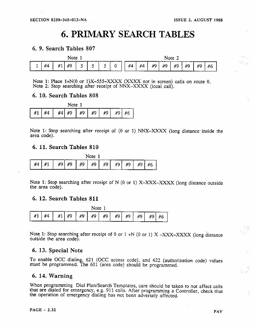
SECTION 8350-345013-NA ISSUE 2, AUGUST 1988
6. PRIMARY SEARCH TABLES 6. 9. Search Tables 807
Note 1 Note 2
1 #4 #l #9 5 5 5 0 #4 #4 #9 #9 #9 #9 #9 #6
Note 1: Place l+N(O or 1)X-555-XxXx (XXXX not in screen) calls on route 0. Note 2: Stop searching after receipt of NNX-XXXX (local call).
6. 10. Search Tables 808
#l #4
Note 1
#9 #9 #9 #9 #6
Note 1: Stop searching after receipt of (0 or 1) NNX-XXX% (long distance. inside the area code) D
6. 1%. Search Tables 810 Note 1
Note 1: Stop searching after receipt of N (0 or I) jc-XXX-XxXx (long distance outside the area code).
6. 12. Search Tables 811 Note 1
#l #4 #l #9 #9 #9 #9 #9 #9 #9 #9 #6
Note 1: Stop searching after receipt of 0 or 1 +N (0 or 1) X -XXX-XxXx (long &stance outside the area code).
6. 13. Special Note To enable OCC dialing, 621 (OCC access code), and 622 (authorization code) values must be programmed. The 601 (area code) should be programmed.
6. 14. Warning When programming Dial Plan/Search Templates, care should be taken to not affect calls that are dialed for emergency, e.g. 911 calls. After programming a Controller, check that the operation of emergency dialing has not been adversely affected.
PAGE - 2.32 PAV
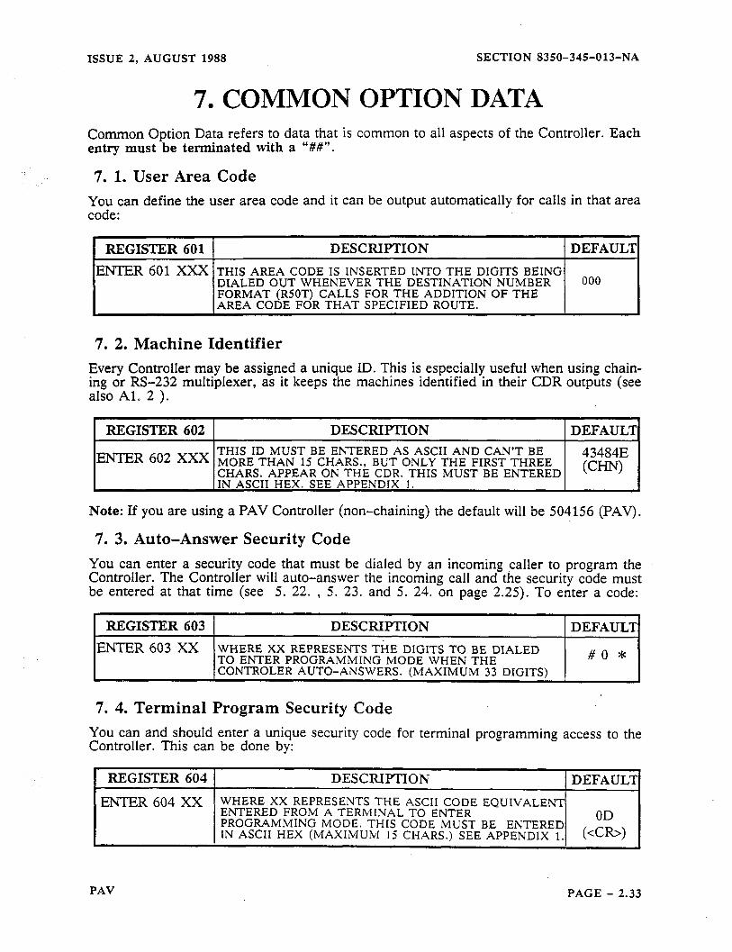
ISSUE 2, AUGUST 1988 SECTION 8350-345013-NA
7. COMMON OPTION DATA Common Option Data refers to data that is common to all aspects of the Controller. Each entry must be terminated with a “W’.
7. 1. User Area Code You can define the user area code and it can be output automatically for calls in that area code:
1 REGISTER 601 1 DESCRIPTION I DEFAUL’I
ENTER 601 xxx THIS AREA CODE IS INSERTED INTO THE DIGITS BEING DIALED OUT WHENEVER THE DESTINATION NUMBER
ooo
FORMAT (RSOT) CALLS FOR THE ADDITION OF THE AREA CODE FOR THAT SPECIFIED ROUTE.
7. 2. Machine Identifier Every Controller may be assigned a unique ID. This is especially useful when using chain- ing or RS-232 multiplexer, as it keeps the machines identified in their CDR outputs (see also Al. 2 ).
REGISTER 602 DESCRIPTION DEFAULT THIS ID MUST BE ENTERED AS ASCII AND CAN’T BE
ENTER 602 xxx MORE THAN 15 CHARS., BUT ONLY THE FIRST THREE 43484E
CHARS. APPEAR ON THE CDR. THIS MUST BE ENTERED KJv IN ASCII HEX. SEE APPENDlX 1.
Note: If you are using a PAV Controller (non-chaining) the default will be 504156 (PAV).
7. 3. Auto-Answer Security Code You can enter a security code that must be dialed by an incoming caller to program the Controller. The Controller will auto-answer the incoming call and the security code must be entered at that time (see 5. 22. , 5. 23. and 5. 24. on page 2.25). To enter a code:
REGISTER 603 DESCRIPTION DEFAULT ENTER 603 xx WHERE XX REPRESENTS THE DIGITS TO BE DIALED
TO ENTER PROGRAIMMING MODE WHEN THE #O * CONTROLER AUTO-ANSWERS. (MAXIMUM 33 DIGITS)
7. 4. Terminal Program Security Code You can and should enter a unique security code for terminal programming access to the Controller. This can be done by:
REGISTER 604 1 DESCRIPTION I
EmR 604 XX WHERE XX REPRESENTS THE ASCII CODE EQUIVALENT ENTERED FROM A TERMINAL TO ENTER PROGRAMMING MODE. THIS CODE IMUST BE ENTERED OD IN ASCII HEX (MAXIMUM 15 CHARS.) SEE APPENDIX 1. ww
PAV PAGE - 2.33
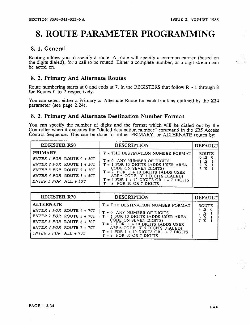
SECTION 835th34§-013-NA ISSUE 2, AUGUST 1988
8. ROUTE PARAMETER PROGRAMMING
8. 1. General Routing allows you to specify a route. A route the digits dialed), for a call to be routed. Either be acted on.
8. 2. Primary And Alternate Routes
will specify a common carrier (based on a complete number, or a digit stream can
Route numbering starts at 0 and ends at 7. In the REGISTERS that follow R = 1 through 8 for Routes 0 to 7 respectively.
You can select either a Primary or Alternate Route for each trunk as outlined by the X24 parameter (see page 2.24).
8. 3. Primary And Alternate Destination Number Format You can specify the number of digits and the format which will’ be dialed out by the Controller when it executes the ““dialed destination number” command in the 6R5 Access Control Sequence. This can be done for either PRIMARY, or ALTERNATE routes. by:
ENTER 4 FOR ROUTE 3 + 50T
ENTER .5 FOR ALL + 5QT
ROUTE 4 + 70T ENTER 2 FOR ROUTE 5 + 70T
ENTER 4 FOR ROUTE 7 + 70T ENTER 5 FOR ALL + 70T
PAGE - 2.34 PAV

ISSUE 2, AUGUST 1988
8. ROUTE
SECTION 8350-345-013-NA
PARAMETER PROGRAMMING 8. 4. Route Progress Tones
You can specify tones to be supplied to a caller, that keep the caller informed as to the progress of a call (being routed). The tones are 400 ms long with a 400 ms space of silence in between by default ( 015 see page 2.17 for information to change these tones to 100 ms long with a 100 ms space of silence in between). These tones are heard by the caller before the Controller cuts-through to the C.O.. This can be done for either PRI- MARY, or ALTERNATE routes by:
REGISTER R51 DESCRIPTION DEFAUL? PRIMARY WHERE T IS: ENTER I FOR ROUTE 0 + 51T 0 = NONE
ROUTE ENTER 2 FOR ROUTE 1 + SlT 1 = J 01s 0 ENTER 3 FOR ROUTE 2 + 51T 2 = JJ 11s 9
ENTER 21s 9
4 FOR ROUTE 3 + 51T 3 = JJI 31s 9 ENTER 5 FOR ALL + 5lT 4 = JJJJ
5 = JJW=J 6 = JJJJJ$
JU=JJJ=J= 8’ 1 JJXJJJJ
REGISTER R71 DESCRIPTION DEFAUL’I ALTERNATE WHERE T IS: ENTER .I FOR ROUTE 4 + 71T O=NONE 0
.ENTER 2 FOR ROUTE 5 + 71T 1 = J= ENTER 3 FOR ROUTE 6 + 7fT 2 = &j= ENTER 4 FOR ROUTE 7 + 71T 3 = JIJ ENTER 5 FOR ALL + 71T 4 = JJPJ
5 = JJJJJ. 6 = pd=Ja!-IJ
PAV PAGE - 2.35
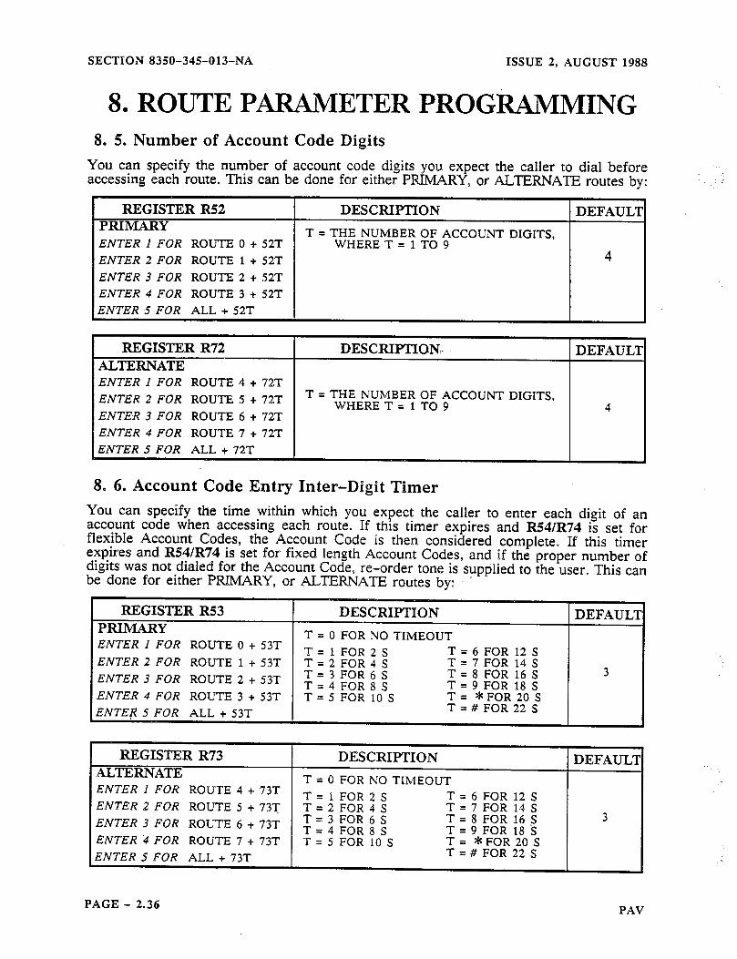
SECTION 8350-345-013-NA ISSUE 2, AUGUST 1988
8, ROUTE PARAMETER PROGRAMMING 8. 5. Number of Account Code Digits
You can specify the number of account code digits you expect the caller to dial before accessing each route. This can be done for either PRIMARY, or ALTERNATE routes by:
REGISTER R52 PRIMARY
DESCXIPTION DEFAUL’I
ENTER 1 FOR ROUTE 0 + 52T T = THE NUMBER OF ACCOUNT DIGITS,
WHERE T = 1 TO 9 ENTER 2 FOR ROUTE 1 + 52T 4
ENTER 3 FOR ROUTE 2 + 52T
ENTER 4 FOR ROUTE 3 + 52T
ENTER 5 FOR ALL t 52T
REGISTER R72 DESCRIPTION:- DEFAULl ALTERNATE ENTER 1 FOR ROUTE 4 t Y2T
ENTER 2 FOR ROUTE 5 + 72T T = THE NUMBER OF ACCOUNT DIGITS, WHERE T = 1 TO 9 4
ENTER 3 FOR ROUTE 6 + 72T
ENTER 4 FOR ROUTE 7 + 72T
ENTER 5 FOR ALL + 72T
8. 6. Account Code Entry Inter-Digit Timer You can specify the time within which you expect the caller to enter each digit of an account code when accessing each route. If this timer expires and R54/R74 is set for flexible Account Codes, the Account Code is then considered complete. If this timer expires and R54/R74 is set for fixed length Account Codes, and if the proper number of digits was not dialed for the Account Code, re-order tone is supplied to the user. This can be done for either PRIMARY, or A.LTEXNAm routes by: ’
ENTER 1 FOR ROUTE 0 + 53T T = 1 FOR 2 S = 6 FOR 12 S ENTER 2 FOR ROUTE 1 + 53T T = 2 FOR 4 S = 7 FOR 14 S ENTER 3 FOR ROUTE 2 53T T = t 3 FOR 6 S = 8 FOR 16 S
T = 4 FOR 8 S = 9 FOR 18 S ENTER 4 FOR ROUTE 3 t 53T T = 5 FOR 10 S ENTER 5 FOR ALL t 53T = # FOR 22 S
REGISTER R73 ALTERNATE! ENTER 1 FOR ROUTE 4 t 73T
ENTER 2 FOR ROUTE 5 t 73T
ENTER 3 FOR ROUTE 6 t 73T
ENTER ‘4 FOR ROUTE 7 t 73T
ENTER 5 FOR ALL t Y3T
DESCRIPTION DEFAUL’I
FOR NO TIMEOUT
FOR 2 S = FOR 4 S ;= FOR 6 S = FOR 8 S ;= FOR 10 S =
;=
6 FOR 12 S 7 FOR 14 S 8 FOR 16 S 9 FOR 18 S *FOR 20 S
# FOR 22 S
3
PAGE - 2.36 PAV
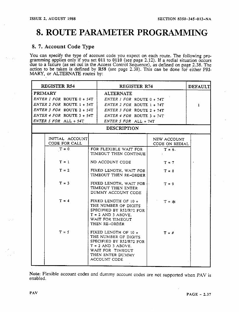
ISSUE 2, AUGUST 1988 SECTION 8350-345-013-NA
8. ROUTE PARAMETER PROGRAMMING
8. 7. Account Code Type
You can specify the type of account code you expect on each route. The following pro- gramming applies only if you set 011 to 0110 (see page 2.12). If a redial situation occurs due to a failure (as set out in the Access Control Sequence), as defined on page 2.38. The action to be taken is defined by R58 (see page 2.38). This can be done for either PFU- MARY, or ALTERNATE routes by:
A
REGISTER R54
PRIMARY
REGISTER R74 DEFAULl
ALTERNATE . ENTER I FOR ROUTE 0 + 54T ENTER 1 FOR ROUTE 0 + 74T
ENTER 2 FOR ROUTE 1 + 54T ENTER 2 FOR ROUTE 1 + 74T 1 ENTER 3 FOR ROUTE 2 + 54T ENTER 3 FOR ROUTE 2 + 74T ENTER 4 FOR ROUTE 3 + 54T ENTER 4 FOR ROUTE 3 + 74T
ENTER 5 FOR ALL + 54T ENTER 5 FOR ALL + 74T
DESCRIPTION
INITIAL ACCOUNT NEW ACCOUNT CODE FOR CALL CODE ON REDIAL
T=O FOR FLEXIBLE WAIT FOR T= 6. TIMEOUT THEN CONTINUE
T=l NO ACCOUNT CODE T=7
T=2 FIXED LENGTH, WAIT FOR T=8 TIMEOUT THEN RE-ORDER
T=3 FIXED LENGTH, WAIT FOR T=9 TIMEOUT THEN ENTER DUMMY ACCOUNT CODE
T=4 FIXED LENGTH OF 10 + . T=* THE NUMBER OF DIGITS SPECIFIED BY R52/R72 FOR T = 2 AND 3 ABOVE. WAIT FOR TIiMEOUT THEN RE-ORDER
T=5 FIXED LENGTH OF 10 + T=# THE NUMBER OF DIGITS SPECIFIED BY R52/R72 FOR T = 2 AND 3 ABOVE. WAIT FOR TIMEOUT THEN ENTER DUMMY ACCOUNT CODE
Note: Flexible account codes and dummy account codes are not supported when PAV is enabled.
PAV PAGE - 2.37
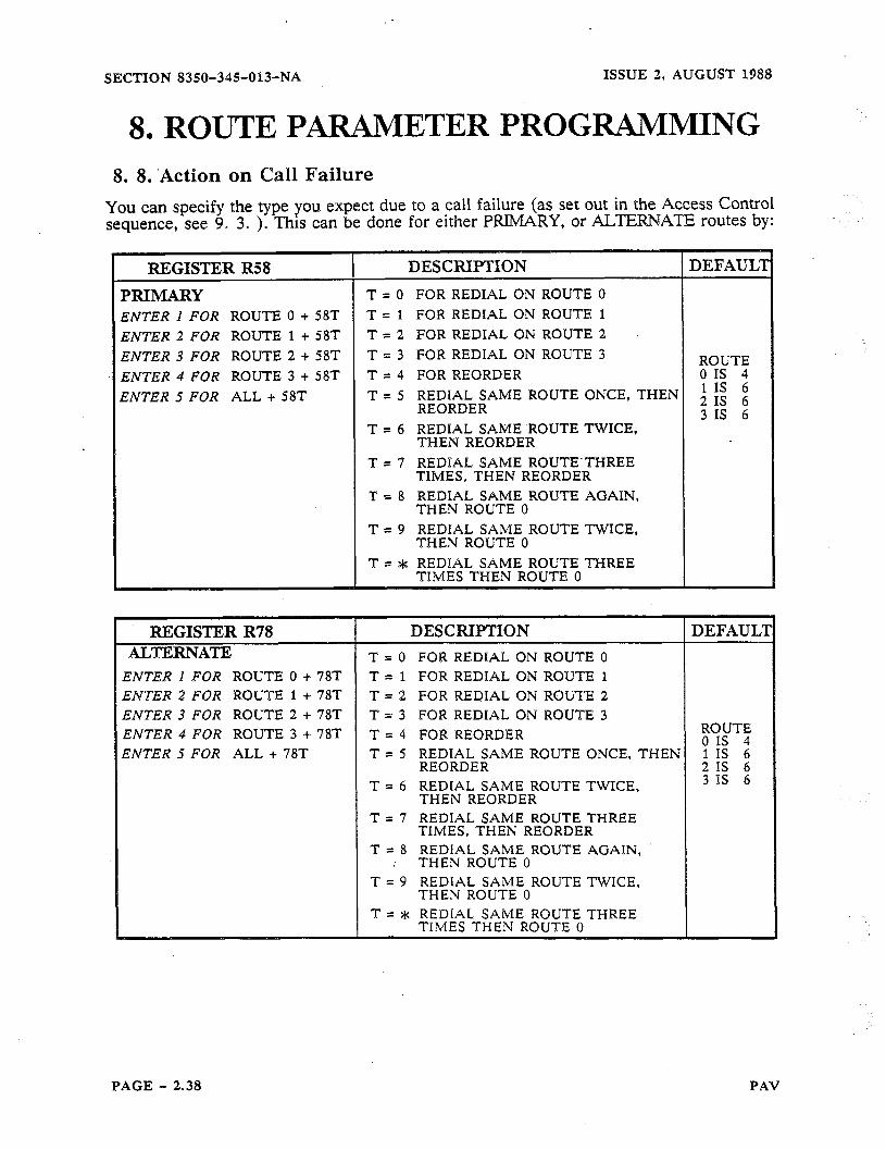
SECTION 8350-345-Of3-NA
8, ROUTE PARAMETER PROGRAMMING 8. 8. ‘Action on Call Failure
You can specify the type you expect due to a call failure (as set out in the Access Control sequence, see 9. 3. )O This can be done for either PRIMARY, or ALTEwG6Am routes by:
ENTER I FOR ROUTE 0 + 58T T = 1 FOR REDIAL ON ROUTE 1
ENTER 2 FOR ROUTE 1 + 58T T = 2 FOR REDIAL ON ROUTE 2
ENTER 3 FOR ROUTE 2 + 58T T = 3 FOR REDIAL ON ROUTE 3
ENTER 4 FOR ROUTE 3 + 58T T = 4 FOR REORDER
ENTER 5 FOR ALL + 58T T = 5 ;;;FDL;AME ROUTE ONCE, THEN
T = 6 REDIAL SAME -ROUTE TWICE, THEN REORDER
T = 7 REDFAL SAME ROUTE”THREE TIMES, THEN REORDER
T = 8 REDIAL SAME ROUTE AGAIN, THEN ROUTE 0
T = 9 REDIAL SAME ROUTE TWICE, THEN ROUTE 0
ENTER 2 FOR ROUTE 1 =I- 78T T = 2 FOR REDIAL ON ROUTE 2 ENTER 3 FOR ROUTE 2 + 78T T = 3 FOR REDIAL ON ROUTE 3 ENTER 4 FOR ROUTE 3 + 78T T = 4 FOR REORDER SNTER 5 FOR ALL + 78T T = 5 REDIAL SAME ROUTE ONCE, THEN
REORDER T = 6 REDIAL SAME ROUTE TWICE,
THEN REORDER T = 7 REDIAL SAME ROUTE THREE
TIMES, THEN REORDER 8 REDIAL SAME ROUTE AGAIN,
: THEN ROUTE 0 ROUTE TWICE,
PAGE - 2.38 PAV

ISSUE 2, AUGUST 1988 SECTION 8350-345-013-NA
S... ROUTE PiiRAMETER PROGRAMMING 8. 9. Account Code Warning Tones
You can specify warning tones to be supplied to a caller that start after the expiration of the R53 (timer) for PRIMARY Routes, or R73 (timer) for ALXERNATE Routes. The tones are 400 ms long with a 400 ms space of silence in between If the caller fails to enter a digit before the specified number of tones expires, the user will receive re-order tone (of 200 ms ON, 200 ms OFF), and will have to restart the call. This can be done by:
REGISTER R59 DESCRIPTION DEFAULTI PRIMARY WHERE T IS:
ENTER P FOR ROUTE 0 + 59T O=NONE 0
ENTER 2 FOR ROUTE 1 + 59T 1 = ar ENTER 3 FOR ROUTE 2 + 59T 2 = JJ ,. ENTER 4 FOR ROUTE 3 + 59T 3 = Jj=J ENTER 5 FOR ALL + 59T 4 = U-H
5 P JXJJ 6 = JJ$JIJ
JJJJJJJ : : J=JJaiXl=JJ
REGISTER R79 DESCIiII’TION DEFAULII
ALTERNATE WHERE T IS:
ENTER 1 FOR ROUTE 0 + 79T O=NONE 0
ENTER 2 FOR ROUTE 1 + 79T 1 = ai-
ENTER 3 FOR ROUTE 2 + 79T 2 = .i=J-
ENTER 4 FOR ROUTE 3 + 79T 3 = JpJ ENTER 5 FOR ALL + 79T 4 = JJ-JJ=
5 = J=HJJ- 6 = JrJJi-1
PAV PAGE..- 2.39
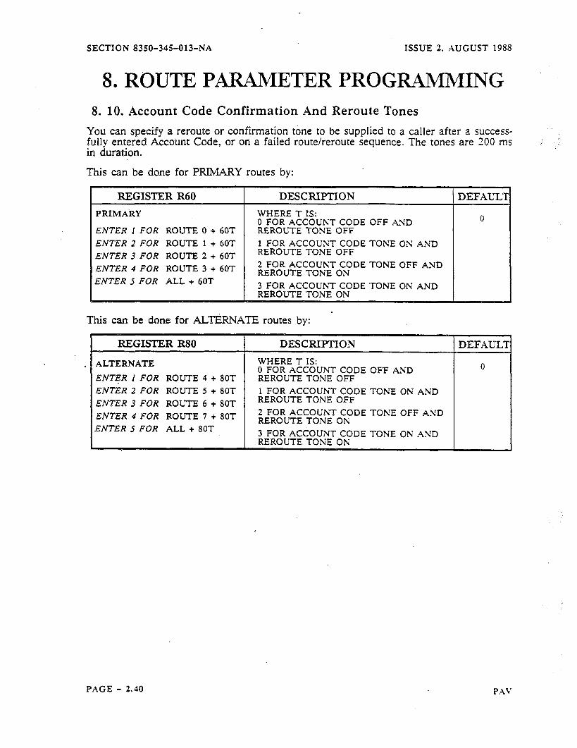
SECTION 8350-345-013-NA XSSUE 2. AUGUST 1988
8. ROUTE PARAMETER PROGRAMMING 8. 10. Account Code Confirmation And Reroute Tones
YOU can spesify a reroute or confirmation tone to be supplied to a caller after a success- fully entered Account Code, or on a failed route/reroute sequence. The tones are 200 ms
I duration.
his can be done for PRIMARY routes by:
ENTER 1 FOR ROUTE 0 + 60T
ENTER 2 FOR ROUTE 1 + 60T
ENTER 3 FOR ROUTE 2 + 60T
i ENTER 4 FOR ROUTE 3 -I- 60T
‘ENTER 5 FOR ALL + 60T
DESCRIFTlON WHERE T IS: 0 FOR ACCOUNT CODE OFF ASD REROUTE TONE OFF 1 FOR ACCOUNT CODE TONE ON AND REROUTE TONE OFF 2FORACCOUNTCODETONEOFFAND REROUTE TONE ON 3FORACCOUNT CODETONEONAND REROUTETONE ON
This can be done for ALTJZRNATE routes by:
REGISTER R80 DESCRIPTION
ALTERNATE ENT+R 1 FOR ROUTE 4 + 80T ENTER2 FOR ROUTE 5 + 8OT ENTER3 FOR ROUTE 6 + 80T ENTER 4 FOR ROUTE 7 + 80T ENTER 5 FOR ALL + 80T
WHERE T IS: 0 FOR ACCOUI\T CODE OFF AND REROUTE TONE OFF 1 FOR ACCOUNT CODE TONE ON AND REROUTE TONE OFF 2 FOR ACCOUNT CODE TONE OFF AND REROUTE TONE ON 3 FOR ACCOUNT CODE TONE ON AND REROUTE TONE ON
PAGE - 2.40

ISSUE 2, AUGUST 1988 - SECTION 8350-345-013-NA
9. CALL CONTROL DATA ENTRY
9. 1. General Call Control Data defines such system wide information as the Controller’s access num- ber and authorization code. Information entered here provides site specific information and each entry must be terminated with a ##.
9. 2. Route Strings The following TABLE explains the Route relationship to GRO, GRl, 6R2, 6R3, 6R4 and 6R.5. Note: if you program X24 (see page 2.24) to be: X240, X241, X242, X243 the trunk will access Primary Routes 0 Alternate Routes 4 - 7.
- 3. If X24 is set to X244 or greater, the trunk will access
6R0, 6R1, 6R2, 6R3, 6R4, 6R5
PRIMARY ROUTES R = 1 WHEN USING ROUTE’ O(ROC) LOCAL
R = 2 WHEN USING ROUTE l(VAC 1) LONG DISTANCE
R = 3 WHEN USING ROUTE 2(VAC 2) LONG DISTANCE
R = 4 WHEN USING ROUTE 3(VAC 3) LONG DISTANCE
ALTERNATE ROUTES R = 5 WHEN USING ROUTE 4(ROC) LOCAL
R = 6 WHEN USING ROUTE 5(VAC 1) LONG DISTANCE
R = 7 WHEN USING ROUTE 6(VAC 2) LONG DISTANCE
R = 8 WHEN USING ROUTE 7(VAC 3) LONG DISTANCE
VAC Value Added Carrier ROC Regional Operating Company
9. 3. Access Control Sequences (6R5) Access Control Sequences instruct the Controller on how to access a particular carrier telephone network. Entries in this part control how the Controller will access the telephone network. Calls are routed here, after a match in the Search Tables. Each entry (6R5) can be any sequence of commands and there are a maximum of 33 characters per entry.
PAV PAGE - 2.41

SECTION 835O-343-013-NA ISSUE 2, AUGUST 1988
9. CALL CONTROL DATA ENTRY
DESCRIPTION
WHERE R EQUALS l-8 FOR ROUTES
SEE Note 2
#O * DIAL A * #OO DIAL A # #Ol IF THE PREVIOUS COMMAND WAS A 2 (SEE 2
BELOW) A # WILL BE DIALED, UNLESS THE LAST DIGIT DIALED OUT WAS A # THEN NO ACTION WILL BE TAKEN
#02 WAIT FOR ACCOUNT CODE (IS NOT OUTPUT)
DIAL THE DESTINATION NUMBER DIAL THE ROUTE OCC ACCESS NUMBER (6Rl) DIAL THE AUTHORIZATION CODE (6~2)
DIAL .THE TRUNK NUMBER CUT THROUGH, DIALING FINISHED CHANGE TO DTMF DIAL-OUT
#2AB PAUSE. CONTINUE AFTER PAUSE IF A=5. SEE Note 1
#3AB 578-680 HZ DETECTOR SEE Note 1 #4AB 440 HZ DETECTOR SEE Note 1 #5AB 480 HZ RINGBACK DETECTOR SEE Note 1 #6AB 400 HZ DETECTOR SEE Note 1 #7AB 360-620 HZ ENERGY DETECTOR SEE Note 1 #8AB PRECISE DIAL TONE DETECTOR SEE Note 1 #DAB DTMF DETECTOR Note 1,4
t 6R5 DEFAULTS: ENTRIES 615 & 655 TO #85327 and 625, 635. 645, 665, 675 AND 685 DEFAULTS: #8533#62*427
Note 1 Refer to Table on next page
Note 2 The 6R5 Access Control Sequences are called as a result of a dialed digit match within the Search Tables. At some point in the Search Tables, a route is usually chosen. That route will be one of Routes 0 through 7, which pass control to the appropriate 6R5 Access Control.
Note 3 Can be used for PBX outgoing access code (e.g. 9) Note 4 Can only be entered from a terminal
Example #85327 is the default on Route 0 (615) this string translates to:
#8 53
Wait for a minimum of precise dial tone for up to 6 seconds Is from the A and B dial tone timers (next page) where 5 is the A value - wait for the minimum time for dial tone and 3 is the B value - 6 seconds
2 Dial destination number 7 Cut-through
PAGE - 2,42 PAV
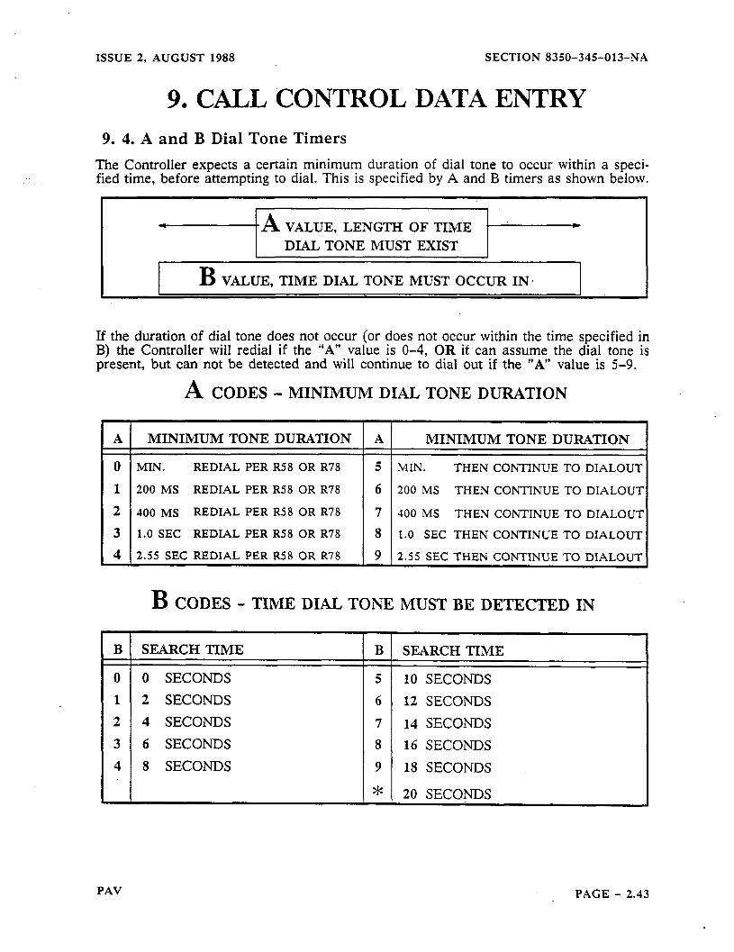
ISSUE 2, AUGUST 1988 SECTION 8350-345-013-NA
9. CALL CONTROL DATA ENTRY 9. 4. A and B Dial Tone Timers
The Controller expects a certain minimum duration of dial tone to occur within a speci- fied time, before attempting to dial. This is specified by A and B timers as shown below.
4 -A VALUE, LENGTH OF TIME .- *
DIAL TONE MUST EXIST
B VALUE, TIME DIAL TONE MUST OCCUR IN.
If the duration of dial tone does not occur (or does not occur within the time specified in B) the Controller will redial if the “A” value is O-4, OR it can assume the dial tone is present, but can not be detected and will continue to dial out if the “A” value is 5-9.
A CODES - MINIMUM DIAL TONE DURATION
A MINIMUM TONE DURATION A MINIMUM TONE DURATION
0 MIN. REDIAL PER R58 OR R78 5 MIN. THEN CONTINUE TO DIALOUT
1 200 MS REDIAL PER R58 OR R78 6 200 MS THEN CONTINUE TO DIALOU-I
2 4130 MS REDIAL PER R58 OR R78 7 JO0 MS THEN CONTINUE TO DIALOU-I
3 1.0 SEC REDIAL PER R58 OR R78 8 1.0 SEC THEN CONTINUE TO DIALOUT
4 2.55 SEC REDIAL PER R58 OR R78 9 2.55 SEC THEN CONTINUE TO DIALOIJT
B
0 1
2
3
4
B CODES - TIME DIAL TONE MUST BE DETECTED IN
SEARCH TIME B SEARCH TIME
0 SECONDS 5 10 SECONDS
2 SECONDS 6 12 SECONDS
4 SECONDS 7 14 SECONDS
6 SECONDS 8 16 SECONDS
8 SECONDS 9 18 SECONDS
* 20 SECONDS
PAV PAGE - 2.43
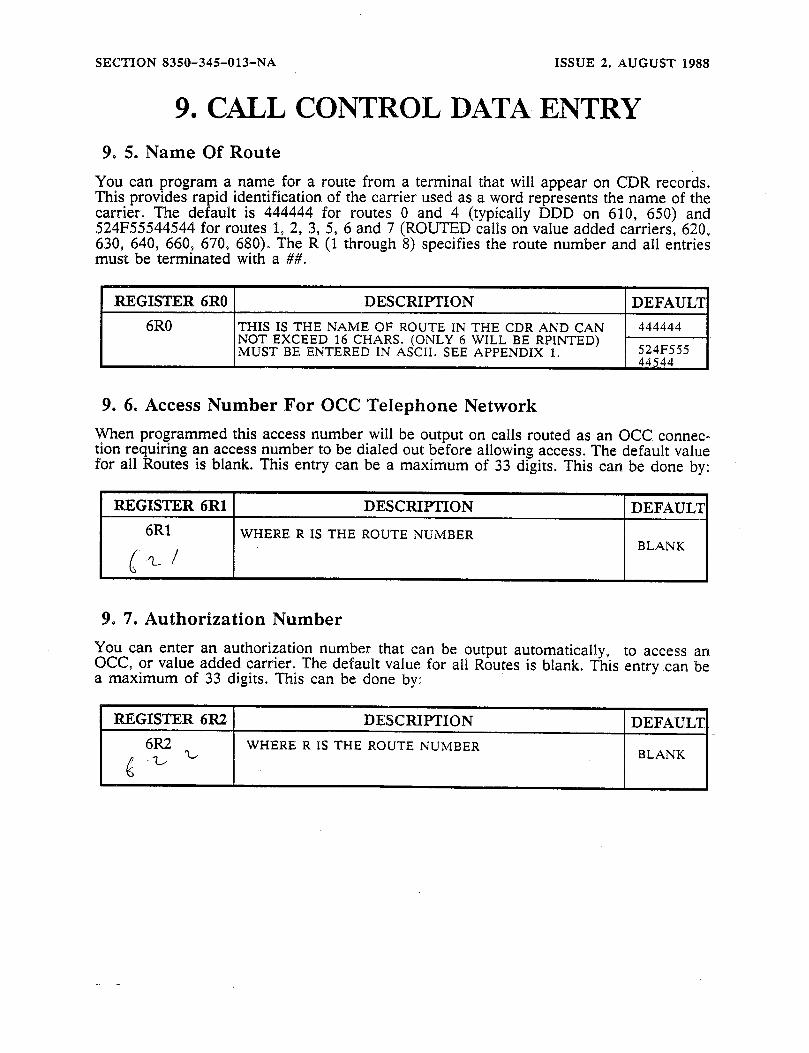
SECTIBN 8350-345013-NA ISSUE 2, AUGUST 1988
9. CALL CONTROL DATA ENTRY 9. 5. Name Of Route
You can program a name for a route from a terminal that will appear on CDR records. This provides rapid identification of the carrier used as a word represents the name of the carrier. The default is 444444 for routes 0 and 4 (typically DDD on 610, 650) and 524F55544544 for routes 1, 2, 3, 5, 6 and 7 (ROUTED calls on value added carriers, 620, 630, 640, 660, 670, 680). The R (1 through 8) specifies the route number and all entries must be terminated with a ##.
REGISTER 6R0 DESCRIIYI’ION DEFAULT
6R0 THIS IS THE NAME OF ROUTE IN THE CDR AND CAN 444444 NOT EXCEED 16 CHARS. (ONLY 6 WILL BE RPINTED) MUST BE ENTERED IN ASCII. SEE APPENDIX 1. 524F555 . ._. .
9. 6. Access Number For OCC Telephone Network When programmed this access number will be output on calls routed as an OCC. connec- tion requiring an access number to be dialed out before allowing access. The default value for all Routes is blank. This entry can be a maximum of 33 digits. This can be done by:
RJZGISTER 6Rl DESCRIPTION DEFAUL?
6Rl WHERE R IS THE ROUTE NUMBER
G d BLANK
9. 7. Authorization Number You can enter an authorization number that can be output automatically, to access an OCC, or value added carrier. The default value for all Routes is blank. This entry can be a maximum of 33 digits. This can be done by:
REGISTER 6R2 DESCRIl?TION DEFAULT.
6Ft2 WHERE R IS THE ROUTE NUMBER
$ ,7_J 2/
BLANK
PAGE - 2.44 PAV
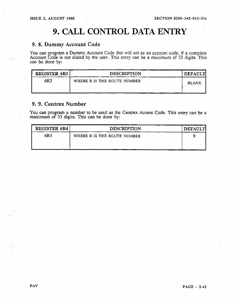
ISSUE 2. AUGUST 1988 SECTION 8350-345-013-NA
9. CALL CONTROL DATA ENTRY 9. 8. Dummy Account Code
You can program a Dummy Account Code that will act as an account code, if a complete Account Code is not dialed by the user. This entry can be a maximum of 33 digits. This can be done by:
REGISTER 6R3 DESCRIPTION DEFAUL’J
6R3 WHERE R IS THE ROUTE NUMBER BLANK
9. 9. Centrex Number
You can program a number to be used as the Centrex Access Cbdk. This entry can be a maximum of 33 digits. This can be done by:
REGISTER 6R4 t D&XIPTION 1 DEFAULT
I WHERE R IS THE ROUTE NUMBER
PAV PAGE - 2.45
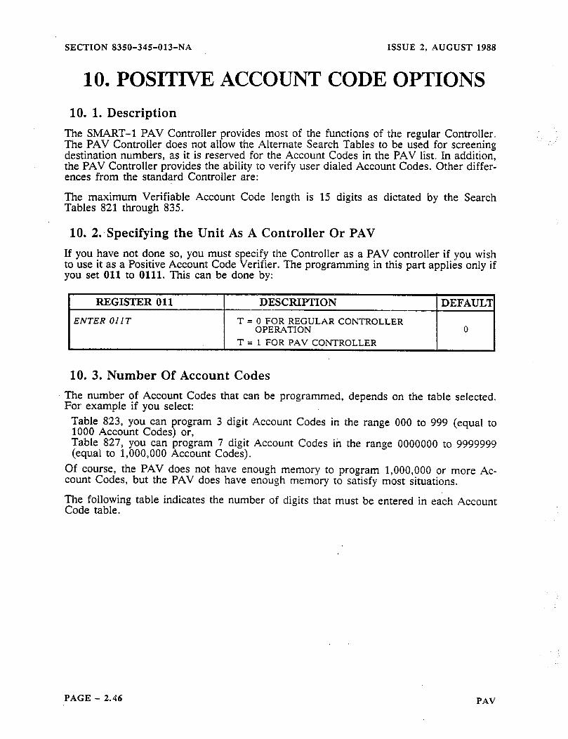
SECTION 8350-345-013-NA ISSUE 2. AUGUST 1988
10. POSITIVE ACCOUNT CODE OPTIONS
10. 1. Description l%e SMART-l PAV Controller provides most of the functions of the regular Controller. The PAV Controller does not allow the Alternate Search Tables to be used for screening destination numbers, as it is reserved for the Account Codes in the PAV list. In addition, the PAV Controller provides the ability to verify user dialed Account Codes. Other differ- ences from the standard Controller are:
The maximum Verifiable Account Code length is 15 digits as dictated by the Search Tables 821 through 835.
10. 2:Specifying the Unit As A Controller Or PAV If you have not done so, you must specify the Controller as a PAV controller if you wish to use it as a Positive Account Code Verifier. The programming in this part applies only if you set 011 to 0111. This can be done by:
REGISTER 011
ENTER 011 T
DESCRIPTION
T = 0 FOR REGULAR CONTROLEER OPERATION
T = 1 FOR PAV CONTRT)I.T.ER
DEFAULT
0
10. 3. Number Of Account Codes The number of Account Codes that can be programmed, depends on the table selected. For example if you select:
Table 823, you can program 3 digit Account Codes in the range 000 to 999 (equal to 1000 Account Codes) or, Table 827, you can program 7 digit Account Codes in the range 0000000 to 9999999 (equal to f,OOO,OOO Account Codes).
Of course, the PAV does not have enough memory to program l,OOO,OOO or more Ac- count Codes, but the PAV does have enough memory to satisfy most situations.
The following table indicates the number of digits that must be entered in each Account Code table.
PAGE - 2.46 PAV
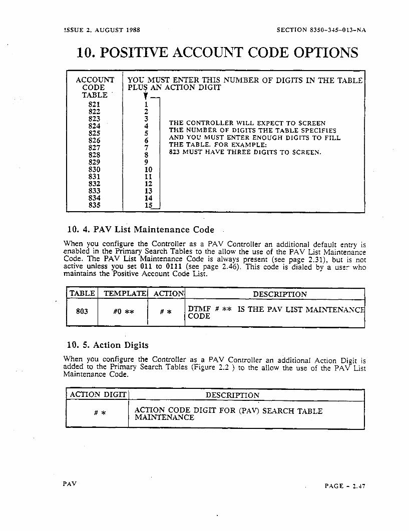
ISSUE 2, AUGUST 1988 SECTION 8350-345-013-NA
10. POSITIVE ACCOUNT CODE OPTIONS
ACCOUNT CODE TABLE.
821 822 823 824 825 826 827 828 829 830 831 832 833 834 835
YOU MUST ENTER THIS NUMBER OF DIGITS IN THE TABLE PLUS AN ACTION DIGIT
THE CONTROLLER WILL EXPECT TO SCREEN THE NUMBER OF DIGITS THE TABLE SPECIFIES AND YOU MUST ENTER ENOUGH DIGITS TO FILL THE TABLE. FOR EXAMPLE: 823 MUST HAVE THREE DIGITS TO SCREEN.
10. 4. PAV List Maintenance Code
When you configure the Controller as a PAV Controller an additional default entrv is enabled in the Primary Search Tables to the allow the use of the PAV List Maintenance Code. The PAV List Maintenance Code is always active unless you set 011 to 0111 (see page
present (see page 2.31), but is not
maintains the Positive Account Code List. 2.46). This code is dialed by a user who
TABLE1 TEMPLATE1 ACTION1 . I I I
DESCRIPTION
803 #O ** I 1
#* DTMF # ** IS THE PAV LIST MAINTENANC CODE
10. 5. Action Digits
When you configure the Controller as a PAV Controller an additional Action Digit is added to the Primary Search Tables (Figure 2-2 Maintenance Code.
) to the allow the use of the PAVr List
ACTION DIGIT DESCRIPTION
#* ACTION CODE DIGIT FOR (PAVJ SEARCH TABLE MAINTENANCE
PAV PAGE - 1.47
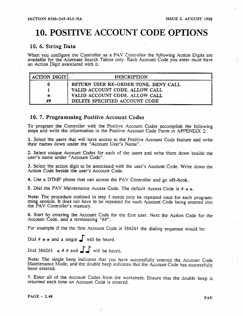
SECTION 8350-345013-NA ISSUE 2, AUGUST 1988
10. POSITIVE ACCOUNT CODE .OPTIONS 10. 6. String Data
When you configure the Controller as a PAV Controller the following Action Digits are available for the Alternate Search Tables only. Each Account Code you enter must have an Action Digit associated with it.
1 AcTION DIGIT1 ’ DESCRIPTION
0 RETURN USER =-ORDER TONE. DENY CALL 1 VALID ACCOUNT CODE. ALLOW CALL * VALID ACCOUNT CODE. ALLOW CALL
#9 DELETE SPECIFIED ACCOUNT CODE
10. 7. Programming Positive Account Codes
To program the Controller with the Positive Account Codes accomplish the following steps and write the information. in the Positive Account Code Form in APPENDIX 2:
1. Select the users that will have access to the Positive Account Code feature and write their names down under the “Account User’s Name”.
2. Select unique Account Codes for each of the users and write them down beside the user’s name under ‘“Account Code”.
3. Select the action digit to be associated with the user’s Account Code. Write down the Action Code beside the user’s Account Code.
4. Use a DTh4F phone that can access the PAV Controller and go off-hook.
5. Dial the PAV Maintenance Access Code. The default Access Code is # L *.
Note: The procedure outlined in step 5 needs only be repeated once for each program- ming session It does not have to be repeated for each Account Code being entered into the PAV Controller’s memory.
6. Start by entering the Account Code for the first user. Next the Action Code for the Account Code,
For example if
Dial # * * and
and a terminating “##“.
the the first Account Code is 386261 the dialing sequence would be:
a single J- will be heard. ~
l-r Dial 386261 * # # and J J will be heard.
Note: The single beep, indicates that you have successfully entered the Account Code Maintenance Mode, and the double beep indicates that the Account Code has successfully been entered.
7. Enter all of the Account Codes from the worksheet. Ensure that the double beep is returned each time an Account Code is entered.
PAGE - 2.48 PAV

ISSUE 2, AUGUST 1988 . SECTION 8350-345-013-NA
10. POSITIVE ACCOUNT CODE OPTIONS Note: Once one line that is connected to the Controller has been programmed, all lines connected to that particular Controller are programmed with these same Account Codes. If there are multiple Controllers in an installation, each Controller must be programmed . separately to use the Account Codes from all lines that are connected to the them.
8. After entering all the Account Codes from the worksheet, simply hang up the phone. This action terminates the programming session, and the Controller is now programmed with the Account Codes.
PAV PAGE - 2.49
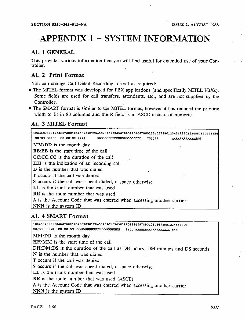
SECTION 8350-345-013-NA
APPENDIX Al. 1 GENERAL
ISSUE 2, AUGUST $988
1 - SYSTEM INFORMATION
This provides various information that you will find useful for extended use of your Con- troller.
Al. 2 Print Format
You can change Call Detail Recording format as required: l The MITEL format was developed for PBX applications (and specifically MTTEL PBXs).
Some fields are used for call transfers, attendants, etc., and are not supplied by the Controller.
l The SMART format is similar to the MOTEL format, however it has reduced the printing width to fit in 80 columns and the R field is in ASCII instead of numeric.
Al. 3 MITEL Format
MY/DD BB:BB CC:CC:CC II.11 DDDDDDDDDDDDDDDDDDDDDDD TSEERR AAAAAAAAAAAANNN
MM/DD is the month day BB:BB is the start time of the call CC:CC:CC is the duration of the call .
11161 is the indication of an incoming call D is the number that was dialed T occurs if the call was denied S occurs if the call was speed dialed, a space otherwise LL is the trunk number that was used RR is the route number that was used A is the Account Code that was entered when accessing another carrier
Al. 4 SMART Format 12345678901234567890123456789012345678Q012345~78901234567890123458789012345078901234507890
MM/DD HH:YY DH:DY:DS NNNNNNNNNNNNNNNNNNNNNNN TSEE RRRRRRAAAAAAAAAAAA NNN
MMIDD is the month day HH:MM is the start time of the call DH:DM:DS is the duration of the call as DH hours, DM minutes and DS seconds N is the number that was dialed T occurs if the call was denied S occurs if the call was speed dialed, a space otherwise LL is the trunk number that was used RR is the route number that was used (ASCll) A is the Account Code that was entered when accessing another carrier NNN is the system ID
PAGE - 2.50 PAV
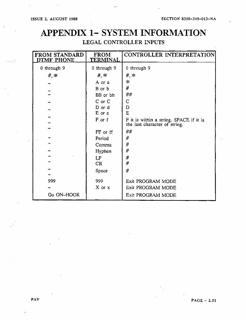
_.-
ISSUE 2, AUGUST 1988 SECTION 8350-345-013-NA
APPENDIX 1- SYSTEM INFORMATION LEGAL CONTROLLER INPUTS
FROM CONTROLLER INTERPRETATIOB TERMINAL
0 through 9
#, *
999 999 Exit PROGRAM MODE X or x Exit PROGRAM MODE
Go ON-HOOK 1 I Exit PROGRAM MODE
0 through 9
#, * A or a B or b BB or bb C or C D or d E or e F or f
FF or ff Period Comma Hyphen LF CR Space
0 through 9
#, * * # ## C D E F it is within a string. SPACE if it is the last character of string.
## # # # # #
#
PAV PAGE - 2.51
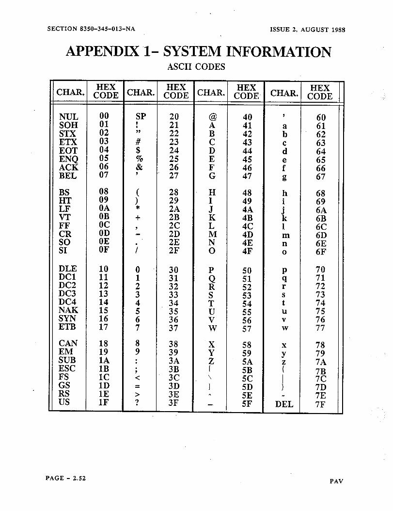
SECTION 8350-345013-NA ISSUE 2, AUGUST 1988
APPENDIX l- SYSTEM INFORMATION ASCII CODES
BS 08 28 H 48 h HT 09
( 68
; 29
: 49 ’ 69
LF OA 2A 4A VT OB
6A =+ 2B
FF oc 9 2c LK
J
:“c k 6B
OD 1 6C
CR - 2D M OE :;
m 6D so 2E N n 6E SI OF i 2F 0 4F 0 6F
DLE 10 0 30 P 70 DC1 11 1 31 71 DC2
z: 12
!l 2 32 RQ
DC3 52 r 72
13 3 33 s 73
DC4
S 53
iz 4 34 T
t NAK 2 35 vu
z4 u ;z SYN 16 36 56 V 76 ETB 17 7 37 W 57 W 77
.cAN 18 8 38 :! 58
%B 19 IA : 9 78
39 59 y” 79 3A
f 5A
ESC 1B ; 7A
3B FS 1c < 3c ’ GS
z ?
;Bc 1D
I = 3D 1
RS 1
1E > 3E 3F :.
z; US
;; 1F ? 5F DEL 7F
PAGE - 2.52 PAV
ISSUE 2, AUGUST 1988 SECTION 8350-345-013-NA
APPENDIX 2 - SITE INFORMATION For your convenience APPENDIX 2 consists of the following site forms:
CONTROLLERSITEFORM
SEARCHTABLEFORM
SPEEDCALLFORM
These forms are designed to help you document your customer’s site information. When calling for technical assistance you should have these forms available to you. The infor- mation contained will aid the technical assistance personnel in resolving difficulties you may encounter.
PAV PAGE - 2.53

SECTION 8350-345-013-NA ISSUE 2. AUGUST 1988
APPENDIX 2 - SITE INFORMATION CONTROLLER SITE FORM
CUSTOMER NAME: DATE SEE SITE
REGISTER DEFAULT DESCRIPTION PAGE lNF0
000 T 1 001 T 0 005 T 0 006 .T 4 007 T 2 008 T 0,l.t 009 T 1 010 T 9 015 T 0
X00 T 2 Type Of Central Office 2.18 X01 T 4 Rotary Dialing Rate 2.18 X02 T 1 DTMF Dialing Rate 2.19 X03 T 6 On-Hook Timing 2.19 X04 T 1 Flash Allowed/Time 2.20 X.05 T 5 Time Between Release And Reseizure 2.20 X06 T 3 T = Number Of Ground Start Tries 2.20 X07 T 3 T = Ground Start Timeout In Seconds 2.21 X08 T 3’ Off-Hook Digit Refusal Time 2.21
.X09 T 4 User Dial Tone 2.21
Xl1 T Xl2 T Xl3 T Xl4 T Xl9 T X20 T
X23 T X24 T X25 T X26 T X2? T X28 T X29 T
X30 T X31 T X32 T X33 T X34 T
R50 T O,l,l,l R51 T 0 R52 T 4 R53 T 3
Speed Call Numbers Reorder Tone Trunks Monitored For CDR RS-232 Baud Rate Nulls After A Carriage Return Print Out Incoming Calls Print Format Route to Monitor for CDR Route Progress Tone Length
2.13 2.16 2.16 2.16 2.16 2.16 2.17 2.17 2.17
Inter-Digit Timeout On Subscriber Side Inter-Digit Timeout On 0+ Calls Inper-Digit Timeout On 01+ Calls Rotary Inter-Digit Pause Beep Options Ringing Sensitivity
2.22 2.22 2.22 2.22 2.23 2.23
Activation Of Controller 2.23 Default Route 2.24 Centrex Outgoing Digit 2.24 Centrex Enable Code 2.24 Auto-Answer Timer In Tens Of Sets 2.25 Auto-Answer Wait-for-Security-Code 2.25 Auto-Answer Lockout Timer 2.25
Off-Hook Recognition Time 2.26 Tip Ground Appiication Timer 2.26 Subscriber Outgoing Digit Recognition 2.26 Subscriber Incoming Digit Recognition 2.27 Tip Ground Removal Timer 2.27
Destination Number Format PAV Route Progress Tones Account Code sumber Of Digits Account Code Wait Timer In Seconds
:-
2.3-1 2.35 2.36 2.36
f In Generic 14 the default is 1. In Generic 10 the default is 0.
PAGE - 2.54 PXV
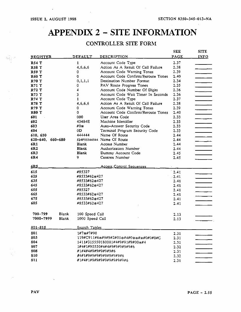
ISSUE 2, AUGUST 1988 SECTION 8350-345-013-NA
APPENDIX 2 - SITE INFORMATION CONTRQLLER SITE FORM
REGISTER SEE SITE
DEFAULT DESCRIPTION PAGE INFO
R54 T R58 T R59 T R60 T R70 T R71 T R72 T R73 T R74 T R78 T R79 T R80 T 601 602 603 604 610, 650 620-640, 660-680 6Rl 6R2 6R3 6R4
1 Account Code Type 2.37 496,696 Action As A Result Of Call Failure 2.38 0 Account Code Warning Tones 2.39 0 Account Code Confirm/Reroute Tones 2.40 O,l,l,l Destination Number Format 2.34 0 PAV Route Progress Tones 2.35 4 Account Code Number Of Digits 2.36 3 Account Code Wait Timer In Seconds 2.36 1 Account Code Type 2.37 4.6.6.6 Action As A Result Of Call Failure 2.38 0 Account Code Warning Tones 2.39 0 Account Code Confirm/Reroute Tones 2.40 000 User Area Code 2.33 43484E Machine Identifier 2.33 #o* Auto-Answer Security Code 2.33 OD Terminal Program Security Code 2.33 444444 Name Of Route 2.44 524F55544S44 Name Of Route 2.44 Blank Access Number 2.44 Blank Authorization Number 2.44 Blank Dummy Account Code 2.45 9 Centrex Number 2.45
615 ~$85327 2.41 625 #8533#62*427 2.41 635 #8533#62*427 2.41 645 #8533#62%427 2.41 655 #85327 2.41 665 #8533#62*427 2.41 675 #8533#62$427 2.41 685 #8533#62*427 2.41
700-799 Blank 100 Speed Call 2.13 7000-7999 Blank 1000 Speed Call 2.13
801-815 Search Tables
801 1#7*#7#90 803 119X9 11#6$#9#9#2#00~#4#O~~#~#O#O#o#C 804 1411#315550180001#4#9#91#9#001#4 807 1#4#1#95550#4#4#9#9#9#9#9#6 808 #1#4#4#9#9#9#9#9#6 810 #4#1#9#9#9#9#9#9#9#9#6 811 #1#4#1#9#9#9#9#9#9#9#9#6
2.31 2.31 2.31 2.32 2.31 2.32 2.31
PAV PAGE - 2.55
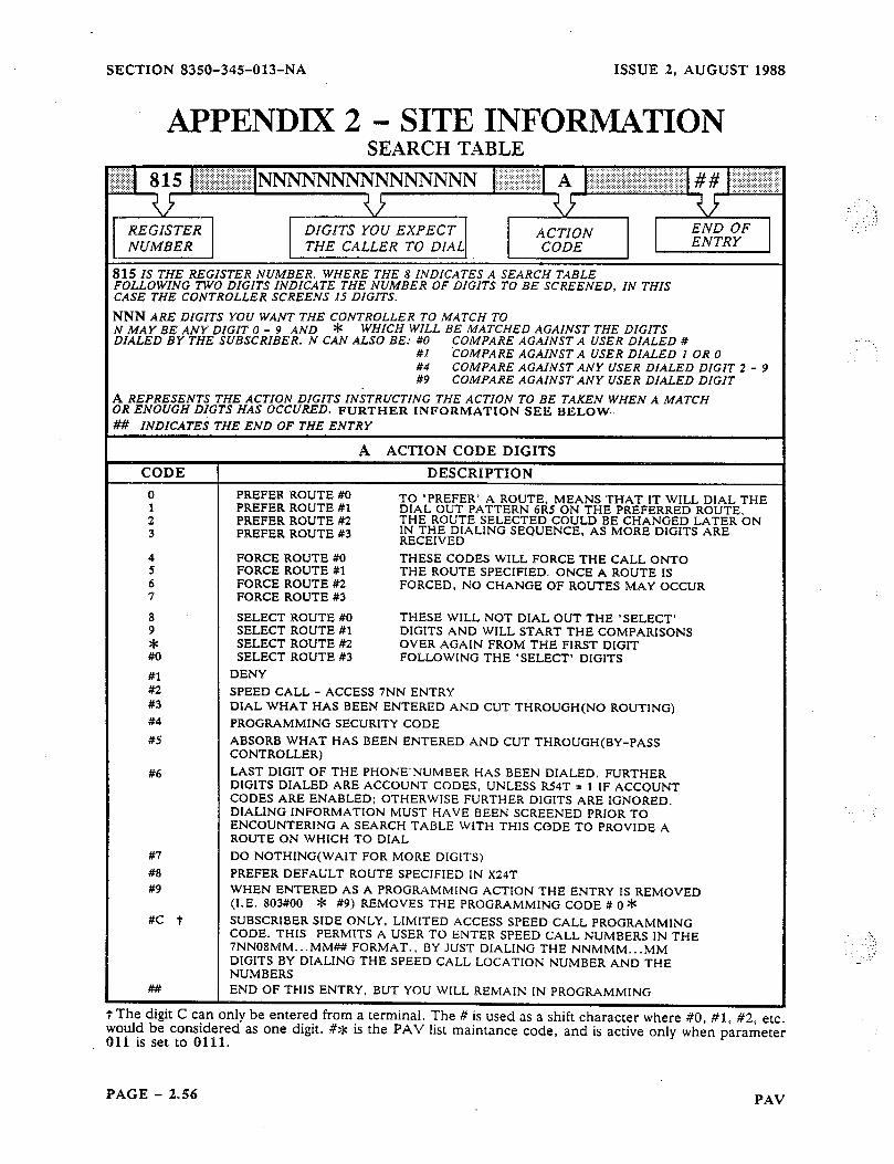
SECTION 8350-345-013-NA ISSUE 2, AUGUST 1988
APPENDIX 2 - SITE INFORMATION SEARCH TABLE
THE CALLER TO DIAL
115 Is THE REGISTER NUMBER. WHERE THE 8 INDICATES A SEARCH TABLE TOLLOWING TWO DIGITS INDICATE THE NUMBER OF DIGITS TO BE SCREENED, IN THIS :ASE THE CONTROLLER SCREENS IS DIGITS.
JNN ARE DIGITS YOU WANT THE CONTROLLER To MATCH TO II MAY BE ANY DIGIT 0 - 9 AND * WHICH WILL BE MATCHED AGAINST THE DIGITS l&LED BY THE SUBSCRIBER. N CAN ALSO BE: #O COMPARE AGAINST A USER DIALED #
#I COMPARE AGAINST A USER DIALED 1 OR 0 #4 COMPARE AGAINST ANY USER DIALED DIGIT 2 - 9 #9 COMPARE AGAlNST ANY USER DIALED DIGIT
L REPRESENTS THE ACTION DIGITS INSTRUCTING THE ACTION TO BE TAKEN WHEN A MATCH )R ENOUGH DIGTS HAS OCCURED. FURTHER INFORMATION SEE BELOW. f# INDICATES THE END OF THE ENTRY
RECEIVED
FORCE ROUTE #O THESE CODES WILL FORCE THE CALL ONTO FORCE ROUTE #l THE ROUTE SPECIFIED. ONCE A ROUTE IS FORCE ROUTE K! FORCED, NO CHANGE OF ROUTES MAY OCCUR FORCE ROUTE #3
SELECT ROUTE #O THESE WILL NOT DIAL OUT THE ‘SELECT’ SELECT ROUTE #1 DIGITS AND WILL START THE COMPARISONS SELECT ROUTE #2 OVER AGAIN FROM THE FIRST DIGIT SELECT ROUTE #3 FOLLOWING THE ‘SELECT’ DIGITS
SPEED CALL - ACCESS 7NN ENTRY DIAL WHAT HAS BEEN ENTERED AND CUT THROUGH(N0 ROUTING) PROGRAMMING SECURITY CODE
ABSORB WHAT HAS BEEN ENTERED AND CUT THROUGH(BY-PASS CONTROLLER) LAST DIGIT OF THE PHONE.NUMBER HAS BEEN DIALED. FURTHER DIGITS DIALED ARE ACCOUNT CODES, UNLESS R54T = 1 IF ACCOUNT CODES ARE ENABLED; OTHERWISE FURTHER DIGITS ARE IGNORED. DIALING INFORMATION MUST HAVE BEEN SCREENED PRIOR TO ENCOUNTERING A SEARCH TABLE WITH THIS CODE TO PROVIDE A ROUTE ON WHICH TO DIAL
DO NOTHING(WAIT FOR MORE DIGITS) PREFER DEFAULT ROUTE SPECIFIED IN X24T WHEN ENTERED AS A PROGRAMMING ACTION THE ENTRY IS REMOVED (I.E. 803#00 * #9) REMOVES THE PROGRAMMING CODE # 0 *
R SIDE ONLY, LIMITED ACCESS SPEED CALL PROGRAMMING S PERMITS A USER TO ENTER SPEED CALL NUMBERS 1N THE ..MMw FORMAT., BY JUST DIALING THE NNMMM.. .MM DIALING THE SPEED CALL LOCATION NUMBER AND THE
T lne aqgr L can only f3e enrerea rrom a would be considered as one digit. #* is 011 is set to 0111.
termmal. the PAV
I he B IS used as a shift character where #O, #l, #2, etc. list maintance code, and is active only when parameter
:‘: .
PAGE - 2.56 PAV
ISSUE 2, AUGUST 1988 SECTION 8350-345-013-NA
APPENDIX 2 - SITE INFORMATION SEARCH TABLE FORM
LOCATION NUMBER ACTION DIGITS
PAV PAGE - 2.57
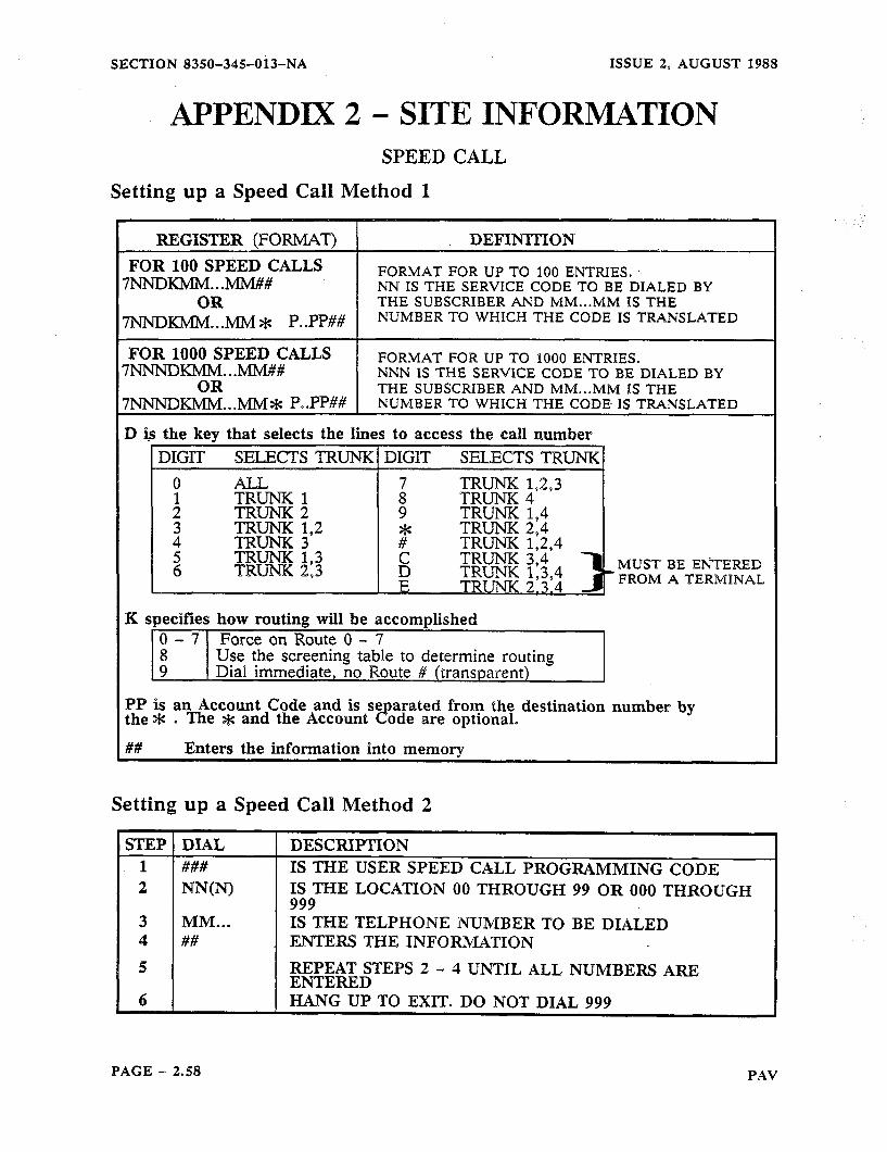
SECTION 8350-345013-NA ISSUE 2, AUGUST 1988
APPENDIX 2 - SITE INFORMATION SPEED CALL
Setting up a Speed Call Method 1
REGISTER (FORMAT) FOR 100 SPEED CALLS
7NNlxMM...MM## OR
7NNDKMM. D MM * P. .PP##
DEFINITION
FORMAT FOR UP TO 100 ENTRIES. NN IS THE SERVICE CODE TO BE DIALED BY THE SUBSCRIBER AND MM...MM IS THE NUMBER TO WHICH THE CODE IS TRANSLATED
FORMAT FOR UP TO 1000 ENTRIES. NNN IS THE SERVICE CODE TO BE DIALED BY THE SUBSCRIBER AND MM...MM IS THE NUMBER TO WHICH THE CODE- IS TRANSLATED
FOR 1000 SPEED CALLS 7NN-NDKMM...MM##
OR 7NNNDKMM...MM* P..PP##
D is the key that selects the lines to access the call number I DIGIT SELECTS TRUNK1 DIGIT SELECTS TRUNK 1
MUST BE’ EI’iTERED FROM A TERMINAL
K specifies how routing will be accomplished 0 - 7 Force on Route 0 - 7
98 Use the screening table to determine routing Dial immediate, no Route # (transparent)
PP is an Account Code and is se the aie . The gc and the Account 3
arated from the destination number by ode are optional.
Enters the information into memory
Setting up a Speed Call Method 2
STEP 1 2
DIAL 1 DESCRIPTION IS THE USER SPEED CALL PROGRAMMING CODE ###
NNU’O IS THE LOCATION 00 THROUGH 99 OR 000 THROUGH 999
3 4
5
MM... IS THE TELPHONE NUMBER TO BE DIALED ## ENTERS THE INFORMATION
REPEAT STEPS 2 - 4 UNTIL ALL NUMBERS ARE ENTERED
6 HANG UP TO EXIT. DO NOT DIAL 999
PAGE - 2.58 PAV

ISSUE 2, AUGUST 1988 SECTION 8350-345013-NA
APPENDIX 2 - SITE INFOR~MATION SPEED CALL FORM
LOCATION NUMBER DESTINATION AND ACCOUNT CODE
I
PAV PAGE - 2.59
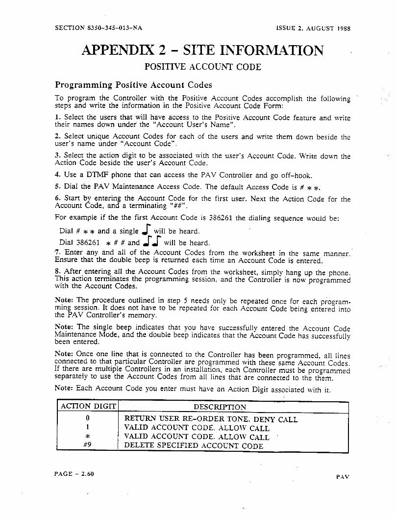
SECTION 835Q-34%013-NA ISSUE 2. AUGUST
APPENDIX 2 - SITE INFORMATION POSITIVE ACCOUNT CODE
Programming Positive Account Codes
1988
To program the Controller with the Positive Account Codes accomplish the following steps and write the information in the Positive Account Code Form: 1. Select the users that will have access to the Positive Account Code feature and write their names down under the “‘Account User’s Name”. 2. Select unique Account Codes for each of the users and write them down beside the user’s name under “Account Code”. 3. Select the action digit to be associated with the user’s Account Code. Write down the Action Code beside the user’s Account Code. 4. Use a DTMP phone that can access the PAV Controller and go off-hook. 5. Dial the PAV Maintenance Access Code. The default Access Code is # * *. 6. Start by entering the Account Code for the first user. Next the Action Code for the Account Code, and a terminating ‘6##‘9- For example if the the first Account Code is 386261 the dialing sequence woulld be:
Dial # * * and a single s will be heard. Dial 386261 * # # and JJ will be heard.
7. Enter any and all of the Account Codes from the worksheet in the same manner. Ensure that the double beep is returned each time an Account Code is entered. 8. After-entering. all the Account Codes from the worksheet, simply hang up the phone. This action terminates the programming session, and the Controller is now programmed with the Account Codes.
Note: The procedure outlined in step 5 needs only be repeated once for each program- ming session It does not have to be repeated for each Account Code being entered into the PAV Controller’s memory. Note: The single beep indicates that you have succ.essfully entered the Account Code Maintenance Mode, and the double beep indicates that the Account Code has successfully been entered. Note: Once one line that is connected to the Controller has been programmed, all lines connected to that particular Controller are programmed with these same Account Codes. If there are multiple Controllers in an installation, each Controller must be programmed separately to use the Account Codes from all lines that are connected to the them. Note: Each Account Code you enter must have an Action Digit associated with it.
MX’ION DIGIT DESCRIPTION 0 RETURN USER RE-ORDER TONE. DENY CXLL 1 VALID ACCOUNT CODE. ALLOW CALL * VALID ACCOUNT CODE. -4LLOW’ CALL
#9 DELETE SPECIFIED .ACCOUNT CODE
PAGE - 2.60 PXV
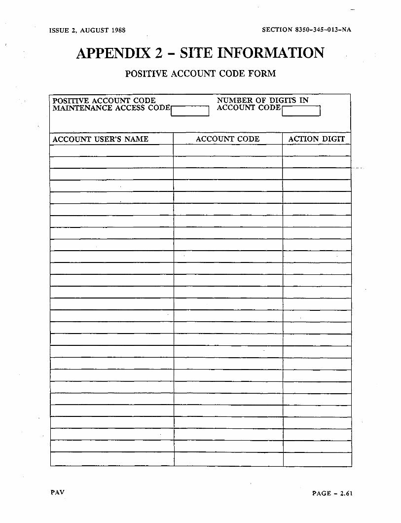
ISSUE 2, AUGUST 1988 SECTION 8350-345013-NA
APPENDIX 2 - SITE INFORMATION POSITWE ACCOUNT CODE FORM
POSITn7E ACCOUNT CODE NUMBER OF DIGITS IN MAINTENANCE ACCESS CODE1 ACCOUNT CODE1
I
ACCOUNT USER’S NAME ACCOUNTCODE ACTION DIGIT
PAV PAGE - 2.61
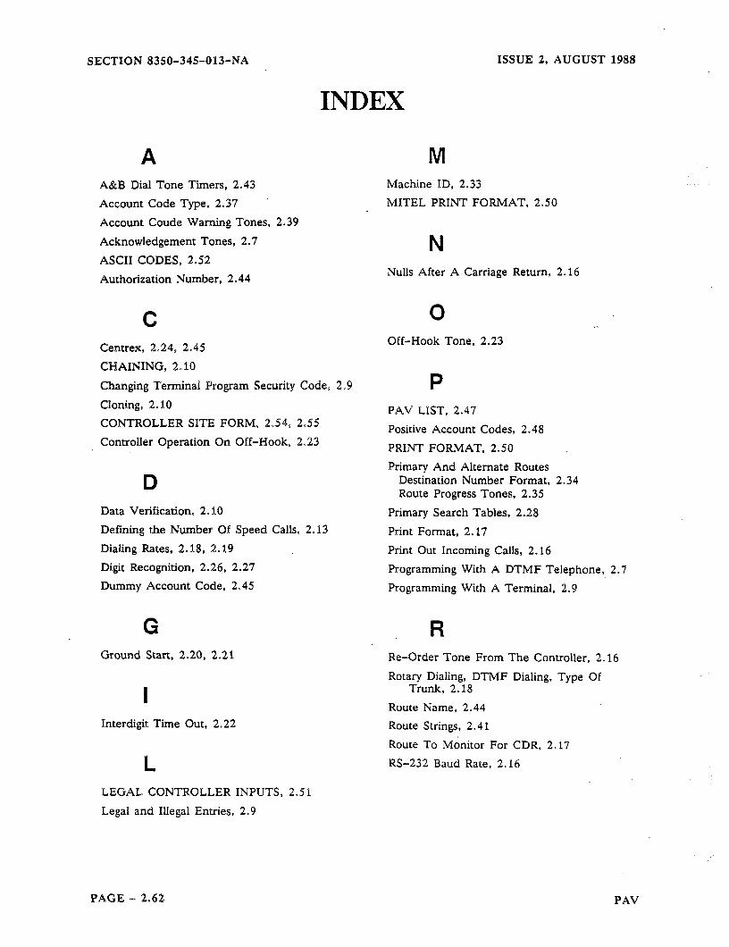
SECTION 8350-34%013-NA ISSUE 2, AUGUST 1988
A A&B Dial Tone Timers, 2.43
Account Code Type, 2.37
Account Coude Warning Tones, 2.39
Acknowledgement Tones, 2.7
ASCII CODES, 2.52 Authorization Number. 2.44
@
INDEX
M
Centrex, 2.24, 2.45
CHAINING, 2 0 10
Changing Terminal Program Security Code, 2.9
Cloning, 2.10 CONTROLLER SITE FORM, 2.54, 2.55
Controller Operation On Off-Hook, 2.23
D Data Verification, 2.10
Defining the Number Of Speed Calls, 2.13
Dialing Rates, 2.18, 2.19 Digit Recognition, 2.26, 2.27
Dummy Account Code, 2.45
G Ground Start, 2.20, 2.21
I Interdigit Time Out, 2.22
e LEGAL CONTROLLER INPUTS, 2.5 1
Legal and Illegal Entries, 2.9
Machine ID, 2.33
MITEL PRINT FORMAT, 2.50
N Nulls After A Carriage Return, 2.16
0 Off-Hook Tone, 2.23
P PAV LIST, 2.47
Positive Account Codes, 2.48
PRINT FORMAT, 2.50 Primary And Alternate Routes
Destination Number Format, 2.34 Route Progress Tones, 2.35
Primary Search Tables, 2.28 Print Format, 2.17
Print Out Incoming Calls, 2.16
Programming With A DTMF Telephone, 2.7
Programming With A Terminal, 2.9
R Re-Order Tone From The Controller, 2.16
Rotary Dialing, DTMF Dialing, Type Of Trunk, 2.18
Route Name, 2.44
Route Strings, 2.41
Route To Monitor For CDR. 2.17
RS-232 Baud Rate, 2.16
PAGE - 2.62 PAV
ISSUE 2, AUGUST 1988
INDEX
S SEARCH TABLE RECORD, 2.57 Search Table Default Data, 2.31 . Search Table Format, 2.30 Security Code, 2.25, 2.33 Setting Up A Speed Call, 2.13, 2.15 SMART PRINT FORMAT, 2.50 SPEED CALL FORM, 2.59 SPEED CALL PROGRAMMING, 2.13 Special Functions, 2.10 Specifying PAV, 2.12
T Tandem IMode, 2.10 Terminating A Varaible Length Entry, 2.7 Terminating A Variable Lenght l&-y. 2.9 -Tip Ground. 2.26,. 2.27
u User Area Code, 2.33 User Dial Tone, 2.21
W Wakeup The Controller, 2.6
SECTION 8350-345013-NA
PAV PAGE - 2.63

ISSUE 1;.“$tJNE 1988 SECTION 83$0-34&014-NA
I
.
MANUAL3
:--
. ; .j . .
:: .: ,y

SECTION 8350-345-014-NA ISSUE 1, JUNE 1988
HEADING .......................................................... 1. INTRODUCTION ............................................ ............. 1. 1. Chaining ............................................................... 2. SETTING UP A CHAIN .................................................... 3. INSTALLATION OF A RECORDING UNIT .................................. 3. 1. Flow Control ............................................................ 4. CHAINING PARAMETERS AND
COMMANDS ............................................................. 5. TONES SUPPLIED BY THE
CONTROLLER .......................................................... 5. 1. Acknowledge DTMF Tones ................................................
PAGE 3.2 3.2
3.3 3.5 3.6
3.7
6. CHAIN PROGRAMMING .................................................. 6. 1. Entering Programming .................................................... 6. 2. Exiting Programming ..................................................... 7. PROGRAMMING AN INDIVIDUAL CONTROLLER ........................... 8. REMOVING A CONTROLLER FROM A CHAIN .............................. 8. REMOVING A CONTROLLER FROM A CHAIN .............................. 9. CHAINING DATA VERIFICATlON ........................................ 10. CDR AND CHAINING .................................................... 10. 1. Polling Scheme ........ . ................................................ 10. 2. CDR Buffering ......................................................... 10. 3. Suspending the CDR ................................................... : 10. 4. Enabling CDR .......................................................... 11. CHAINING CONDITIONS ..................... ............................. 11. 1. Parameter 013 ......................................................... 11. 2. Parameter 014 ......................................................... 11. 3. Chains ................................................................. 11. 4.Other Notes ........................................................... INDEX ..*........................... . . . . . . . . . . . . . . . . . . . . . . . . . . . . . . . . . . . . . . .
3.8 3.8
3.9 3.9 3.9
3.10 3.11 3.12 3.13 3.14 3.14 3.15 3.15 3.15
3.17 3.17 3.17 3.17 3.17
3.19
PAGE - 3.1

ISSUE 1, JUNE 1988 SECTION 8350-345-014-NA
1. INTRODUCTION 1. 1. Chaining
This feature allows multiple Controllers to be ‘“Chained” through their RS-232 port via cabling supplied with each unit (Figure 3.1 ). This Chaining feature provi.des two distinct features:
1. The units which are chained together via their RS-232 ports (cable supplied) may be addressed remotely or locally with DTMF instruments which can access any port on a Controller in a Chain. From that access point any combination of units within the set, may be programmed with DTMF signals. The recommended methods of access might be either a DTMF instrument itself, or a “Tandem” (see MANUAL 4) access from a remote location.
2. With the addition of an optional cable, a printing device may be connected to the Chain. This allows the collection of call records from all units in the Chain, to be output to one printing device without the need for a data concentrator or multiplexer. The call detail records of the units within the chained set will be output one at a time to the printing device. Programming from this device through the printer Chaining cable is not supported.
Figure 3.1 Setting up a Chain
OPTIONAL RS-232 CABLE FOR PRINTER
OR RECORDING
CONNEaION JACK
Ri%%%G DEVICES OR
OPTIONAL RS-232 CONNECTOR
PLUG
PAGE - 3.2

SECTION 83&3JWllJ-NA ISSUE 1, JUNE 1988
I
El I
El
0 I
I I I
I
I
If you
2. SElTmG UP A CHAIN - 1. In&l and power oil the Controllers up individually (maximum of ten), they must not be connecred to each other (see MANUAL 1).
2. You s/zouLd have initialized each Controller (MANUAL 1).
3. At each Controller individually enter the programming access code (default # 0 * see Note 1) and turn the CDR off, by entering 0090.
4. Make sure that all the Controllers are programmed to the same Baud rate (maxi- mum 1200 Baud when the Chaining Cable is attached). Leave the programming mode by either entering 999, or by going On-Hook.
5. Connect a DTMF telephone to a telephone port on a Controller that has not been programmed for an ID (013T).
6. Enter the programming access code of # 0 * from the DTMF. telephone’.
7. Specify rhe Controller number by entering 013T where T is the Controller number (see Note 2). Go On-Hook.
8. Repem steps 5 through 7 for each remaining Controller except the Tail Controller.
9. Poivet all the Controllers down.
10. Attach the Chaining Cab!e to each of the Controllers in the Chain per Figure 3.2 .
11. This step should only be done for the Tail Controller (which must be pro- grammed last). Note: Do not do this until the Chaining cables are connected. Con- nect u DTMF telephone to a telephone port on the Taii Controller. Then power the unit up, and enter programming mode. Enrer 013T where T is the number of the Tail Conuoiler (largest number). Enter Ol4T where T is the number of Controllers in the Chain. T must be the same in both 013T and 014T.
12. To exit programming completely enter 999 or go on-hook.
are using the Optional Printer Chaining Cable, see 3. INSTALLATION OF A RE- XNG UNIT. i.. CORI
AGOODIDEA : As you install the Controilers in a Chain, it is a good idea to label each Controller and
cable, with the labels provided, for programming identification. Note 1: You can not use a terminal to program in a Chain unless you arc in tandem mode
(see MANUAL 4). Note 2: Before doing Chain programming on any of the Controllers in the Chain vou
must assign each contrqller in the Chain a specific number. - !D (1 - P or * ). The first Controller is referred to as the Head and is numbered 1 and the remaining units are numbered and programmed sequentially (e.g. Controller 2, then 3, 4, etc.). The last unit is referred to as the Tail, and is programmed with the highest number in the Chain.
PACE - 3.3
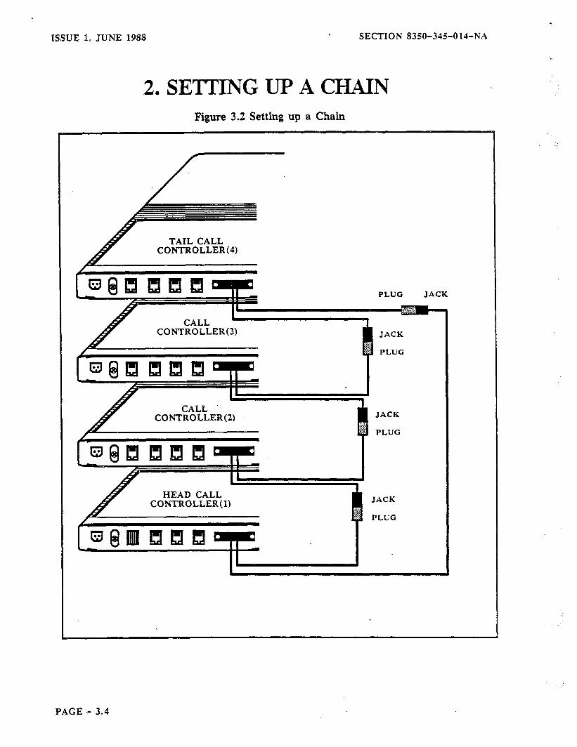
XSSUE 1, JUNE 1988 SECTION 8350-34%014-NA
2. SETTING UP A CHAIN Figure 3.2 Setting up a Chain
CONTROLLER(
TAIL CALL CONTROLLER(4)
PAGE - 3.4

-SECTION 8350-345-014-NA ISSUE 1, JUNE 1988
3. INSTALLATION OF A RECORDING UNIT
The recording device you use must meet the requirements and be installed as indicated in Figure 3.3 .
Figure 3.3 Connecting a Terminal or Printer
TERMINAL SPECIFICATIONS
Parity = None = 8 with 1
Bit 8 Sense = Spat stop bit
eration = Full D
RS-232 CONNECTOR
DIRECTION
You can not program the Controllers with a terminal unless you are using tandem mode.
PAGE - 3.5
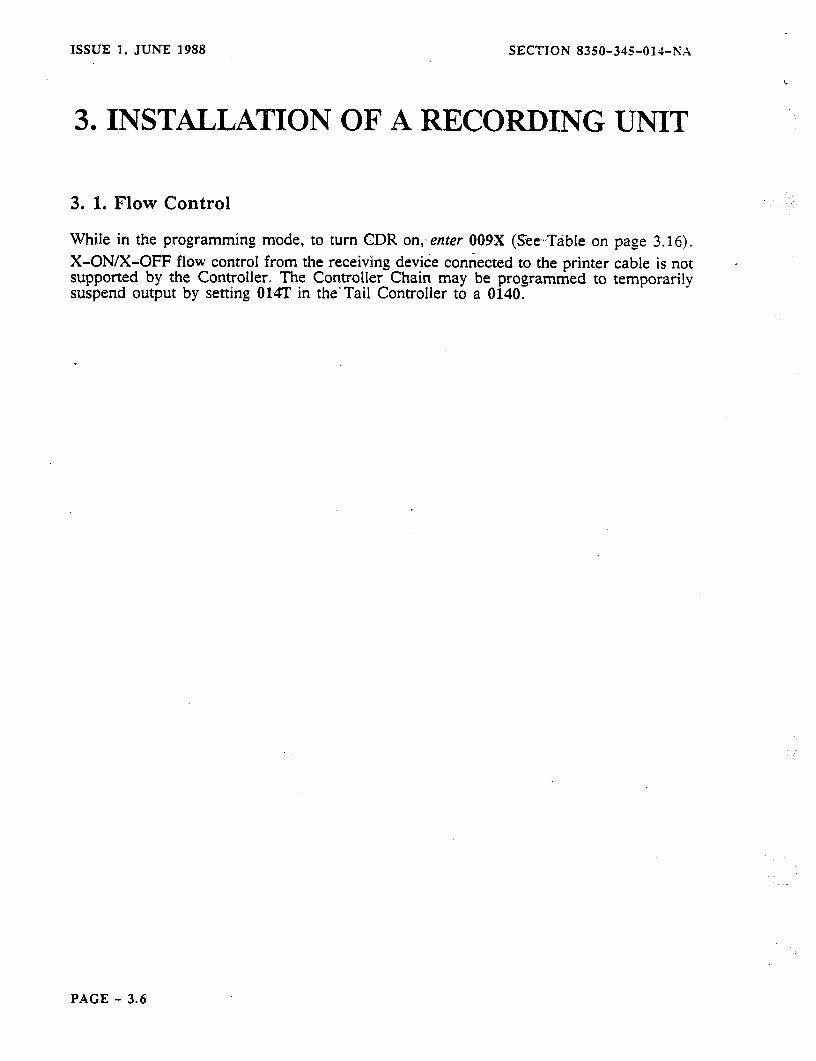
ISSUE I, JUNE 1988 SECTION 8350-345014-h’A
3. INSTALLATION OF A RECORDING UNIT
3. 1. Flow Control
While in the programming mode, to turn CDR on,- crater 009X (See-Ttible on page 3.16). X-ON/X-OFF flow control from the receiving device connected to the printer cable is not supported by the Controller. The Controller Chain may be programmed to temporarily suspend output by setting 014T in the-Tail Controller to a 0140.
PACE - 3.6
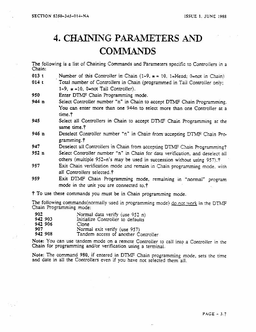
SECTION S350-31%014-NX ISSUE 1. JUNE 1988
The following is a list of Chaining Commands and Parameters specific to Controllers in a Chain: 013 t 014 t
950 944 II
Number of this Controller in.Chain (l-9, t = IO;- l=Head; O=not in Chain) Total number of Controllers in Chain (programmed in Taii Controller only; 1-9, t =IO, O=not Tail Controller). Enter DTMF Chain Programming mode. Select Controller number “n” in Chain to accept DTMF Chain Programming. You can enter more than one 944n to seiect more than one Controller at a time.7
945 Select all Controllers in Chain to accept DTMF Chain Programming at the same time.7
946 n
947 952 n
957
959
Deselect Controller number “n” in Chain from..accepting DTMF Chain Pro- gramming. t Deselect all Controllers in Chain from accepting DTMF Chain Programming? Select Controller number “n” in Chain for data verification, and deseiecr all others (multiple 952-n’s may be used in succession without using 957)-t Exit Chain verification mode and remain in Chain programming mode. with all Controllers selected.? Exit DTMF Chain Programming mode, remaining in “normal” program mode in the unit you are connected to.7
4. CHAINING PARAMETERS AND COMMANDS
t To use these commands you must be in Chain programming mode.
The following commands(normally used in programming mode) do not work in the DTMF Chain Programming mode:
902 942 903
Normal data verify (use 952 n) Initialize Controller to defaults
942 906 Clone 907 942 908
Normal exit verify (use 957) Tandem access of another Controller
Note: You can use tandem mode on a remote Controller to call into ,a Controller in the Chain for programming and/or verification using a terminal.
Note: The command 980, if entered in DTMF Chain programming mode, sets the time and date in all the Controllers even if you have not selected them all.
PACE - 3.7

ISSUE 1. JUNE 1988 SECTION 8350-315Old-N.1
5. TONES SUPPLIED BY THE CONTROLLER
5. 1. Acknowledge DTlMF Tones
While programming the Cdntroller inChain-mode you will receive >audible indications as to correct, incorrect entries and programming timeouts. In general, after each entry, the Controller will respond with a double tone.
If You Hear E
A single DTMP $ means the command you have entered has been recognized as le- gal(correct), i.e. you entered # 0 1.
For Example Parameters: After the three digit parameter prefix has been dialed, the Controller will respond a single short tone. Strines: After the three digit string prefix has been dialed, the Controller will respond a single short tone. Search Tables: After the three digit search table prefix, the Controller will respond a short tone. You will hear E upon entering commands, 952, 946, and 944.
If You Hear EE If you hear a double tone it means the entry you have made has been accepted. This occurs after a parameter has all the digits it needs to make it legal or you entered ## on a variable length parameter. For example: @ If you enter 942 you will hear EE . Then enter 903 and you will hear EE . e If you enter 957 to exit Chain data verification mode you will still be in Chain pro- gramming mode e
In this case when you enter a valid parameter you will hear a P , and when valid data is entered for that parameter you will hear SE .
l You will hear EE at the end of a string, or a parameter that needs a single digit, 950, 947, or after 952 followed by a digit you wish to look at.
If You Hear $J J J
Four long DTMF arLLr means you have made an incorrect programming entry. Note: In the event of an illegal entry, wait for the tones to stop and then try again.
PAGE - 3.8
SECTION 8350-345-014-NA ISSUE 1, JUNE 1988
6. CHAIN PROGRAMMING 6. 1. Entering Programming
You must have given each Controller in the Chain an ID and entered the number of Controllers in the chain in the Tail Controller. By leaving the DTMF telephone connected to a telephone port on any one of the Controllers,,. you-can. program all Controllers simul- taneously with the same information. It is not necessary to use DTMP Chain Program- ming if a Chaining Cable is connected to a Controller; “normal” DTMF programming may still be done for that Controller as before, if desired. If command 950 is entered at a Controller during reeular oroeram mode, it (and the rest of the Chain) enters the DTMF Chain Programming mode. After the programming access code and the 950 command have been entered, programming may be done per normal except for the following:
0 While in the Chaining mode, the Controller does NOT give the one-minute warning as it does in “normal” programming mode; after two minutes of no activity, the Control- ler will exit programming.
0 Only one line, on one Controller, per Chain, may do DTMF Chain Programming at a time. Additional access attempts will be refused.
0 Chaining operations can not be done any faster than 1200 baud. Don’t change 006 (RS-232 Baud Rate) with the Chaining Cable attached, and make sure that all the Controllers are set to the same Baud rate when the Chaining Cable is attached. You can not change the baud rate or set the ID of a Controller while it is in a Chain.
6. 2. Exiting Programming
To exit programming completely enter 999 or go on-hook.
Enter 959, to exit Chain programming mode, but remain in normal programming mode for the Controller you are connected to. Warning:
If you are doing a remote access you must enter 999 before hanging up, or you will leave the trunk locked up until it times out.
PAGE - 3.9

ISSUE 1. JUNE 1988 SECTION 8350-34%014-NA
7. PROGRAMMING AN INDMDUAL CONTROLLER
To program an individual Controller while using Chaining, (you must make sure you ad- dress the correct Controller(s) you wish to program) you can:
‘_ II I. C&nect Q DTMF telephone to a telephone port on any Controller which is in the
Chain and enter the programming access code followed by 950. This starts Chain Programming mode and selects all the Controllers in the Chain for programming.
I] 2. If you want to program all the Controllers in the Chain with the same informa- tion, go to step 4. Otherwise, enter 947 which deselects all Controllers in Chain.
1 1 3. Enter 944 n which selects a specific Controller where n is the unique ID (1 - 9 or dc for 10). This command may be repeated to select more than one Controller in the Chain for programming.
I] 4. Enter the individual programming information for the Controller(s).
1-1 5. To exit programming completely enter 999 or ga on-hook. Enter 959, to exit Chain programming mode, but remain in normal programming mode for the Con- troller you are connected to.
PAGE - 3.10
SECTION 8350-345-014-N.\ ISSUE 1, JUNE 1988
8. REMOVING A CONTROLLER FROM -A CHAIN
Should the requirement occur, you can remove a Controiler from a Chain. The example in Figure 3.4 shows a four controller Chain for simplicity. However, there can be any number of Controllers in the Chain: (up to. IO) :and fanynumber may be removed. Essen- tially, the easiest method of removing a Controller is to remove it, put the Tail Controller in its place and reprogram to the removed Controller’s ID, then reprogram the last Con- troller in the Chain to be the new Tail Controller. The following steps outline this tech- nique
El
in greater detail.
1. Connect a DTMF telephone to a telephone port on the Controller that has been selected for removal. Enter the programming access code.
I I I I
I
I
Note: Controller is powered down.
Any CDR records which have not been output by a Controller are lost if that _. . _ _
2. Enter 0130 (this removes the Controller from the Chain).
3. Go on-hook.
4. Connect a DTMF tele hone to the Tail Controller and enter the programming access code. Enter 0140 deselects this Controller as the Tail, turns off Chaining P activity, and suspends CDR output if it was enabled). Go on-hook. Power all Con- trollers down.
5.
6.
7.
8.
Move the Tail Controller into the position indicated in Figure 3.4 ~
Power up all Controllers.
Connect a DTMF telephone to a telephone port on the old Tail Controller.
Program 013T on the old Tail Controller to match its new position in the Chain. Go on-hook. Connect e DTMF telephone to a telephone port on the new Tail Con- troller.
9. Reprogram 014T on the new Tail Controller with the new total number of Con: trollers in the Chain. This turns on Chaining activity, and starts CDR output if it was enabled.
10. To exit programming completely enter 999 or go on-hook. Enter 959, to exit Chain programming mode, but remain in normal programming mode for the Con- troller you are connected to.
PAGE - 3.11
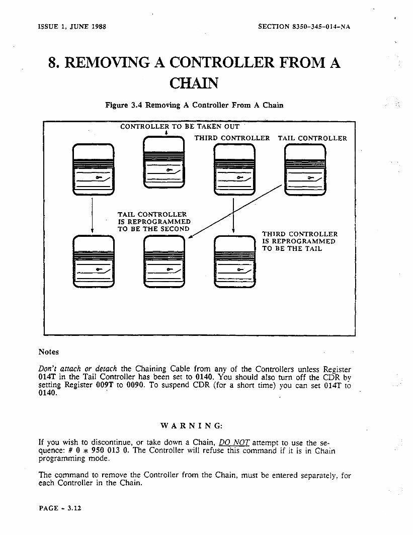
ISSIJE 1, JUNE 1988 SECTION 8350-345014-NA
8, REMOVING A CONTROLLER FROM A CHAIN
Figure 3.4 Removing A Controller From A Chain
CONTROLLE; TO BE TAKEN OUT
THIRD CONTROLLER TAIL CONTROLLER
TAIL CONTROLLER IS REPROGRAMMED TO BE THE SECOND
Notes
Do?z’t attach or detach the Chaining Cable from any of the Controllers unless Register 014T in the Tail Controller has been set to 0140. You should also turn off the CDR by setting Register 009T to 0090. To suspend CDR (for a short time) you can set 014T to 0140.
WARNING:
If you wish to discontinue, or take down a Chain, DO NOT attempt to use the se- quence: # 0 * 950 013 0. The Controller will refuse this command if it is in Chain programming mode.
The command to remove the Controller from the Chain, must be entered separately, for each Controller in the Chain.
PAGE - 3.12
SECTION 8350-345014-NA ISSUE 1, JUNE 1988
9. CHAINING DATA VERIFICATION There are three ways to verify the data in Controllers in a Chain:
A. Use a DTMF telephone on the subscriber side of one line of one of the chained Controllers and a DTMF digit decoder/collector on the C.O. side of the same line;
B. Call in to one of the chained Controllers from a remotely-located DTMF telephone which has a DT..!,d!glt, decoder/collector, connected .in parallel (remote programming);
C. Use a terminal with another Controller in its Tandem mode to call in to one of the chained Controllers.
Using any of these three methods, go into program mode on one of the chained Con- trolllers.
[ ] 1. Enter the 950 command to enter the Chaining mode.
]] 2. Enter 952 n, where n is the number of the Controller in the Chain which you desire to examine.
]] 3. Enter the number of the parameter for which you wish to,verify the value. The value appears on the terminal (tandem mode). or DT’MF digit decoder/collector.
I] 4. Continue entering parameter numbers until you have all your desired informa- tion. You may then verify another Controller by entering 952 n, where n is the number of the next Controller to be verified.
I] 5. To leave the verification mode and remain in the Chaining mode, enter the command 957.
Alternatively, the commands 959 or 999 may be used to exit from Chaining mode and from programming mode respectively, with the expected results.
PAGE - 3.13

P
ISSUE 1, JUNE 1988 SECTION 8350-345014-NA
i
10. CDR AND CHAINING 10. 1. Polling Scheme In the Chain, the Tail Controller queries the other Controllers for their CDR status. The Controller with the most records sends its call records first, through the Chain, to the Tail Controller, which passes them out to the printer cable. This process continues until each Controller has sent all availablerecords..
There is a set of printable and non-printable characters used to perform the polling scheme. These characters are also sent to the printer cable. Characters used were chosen with care to prevent interface problems with popular printers, SMDA equipment, and other call recording devices. A list of characters sent by the Controllers is listed below:
START OF BUFFER STATUS REPORT 1E RS (note 2) END OF BUFFER STATUS REPORT 1C FS (note 2) -\ DUMP CDR COMMAND (START OF BINARY DUMP NR.. 7E. - (note 1) - ELEMENT OF BINARY DUMP NUMBER 01 SOH "A ELEMENT OF BINARY DUMP NUMBER *. 00 NUL -e END OF BINARY DUMP NUMBER SEQUENCE 7E - (note11 -. STA.RT OF CDRDUMP ' END OF CDR DUMP 04 EOT -D DTMF CHAIN PROG. ENTRY CODE INTRODUCTION CHAR 10 DLE -P
Notes: 1. This is a printing character, but it does not normally appear in a CDR record. 2. This character is not sent to the printer.
Example 1
.A line in Controller 3 in a Chain goes on-hook.
<SOH><SOH><SOH -<NULxNUL><SOH><SOH> CRXLF><NULxNUL> [CDR data] CEO
I f T T
A
ENQUIRY COMMAND TO DUMP CDR END-OF-CDR- CHARACTERS CDR IN RECORD(S) DUMP
CONTROLLER 3 CHARACTER START-OF-CDR-
DUMP ENQUIRY CHARACTER CHARACTER
As a printout, the output from the above would be: . a . (previous CDR record)... -w. 01/27 09:49 00:02:34 1315393121 T3 ROUTED CHN
The - may be missing from a multiple-CDR output of consecutive records from one Controller.
PAGE - 3.14
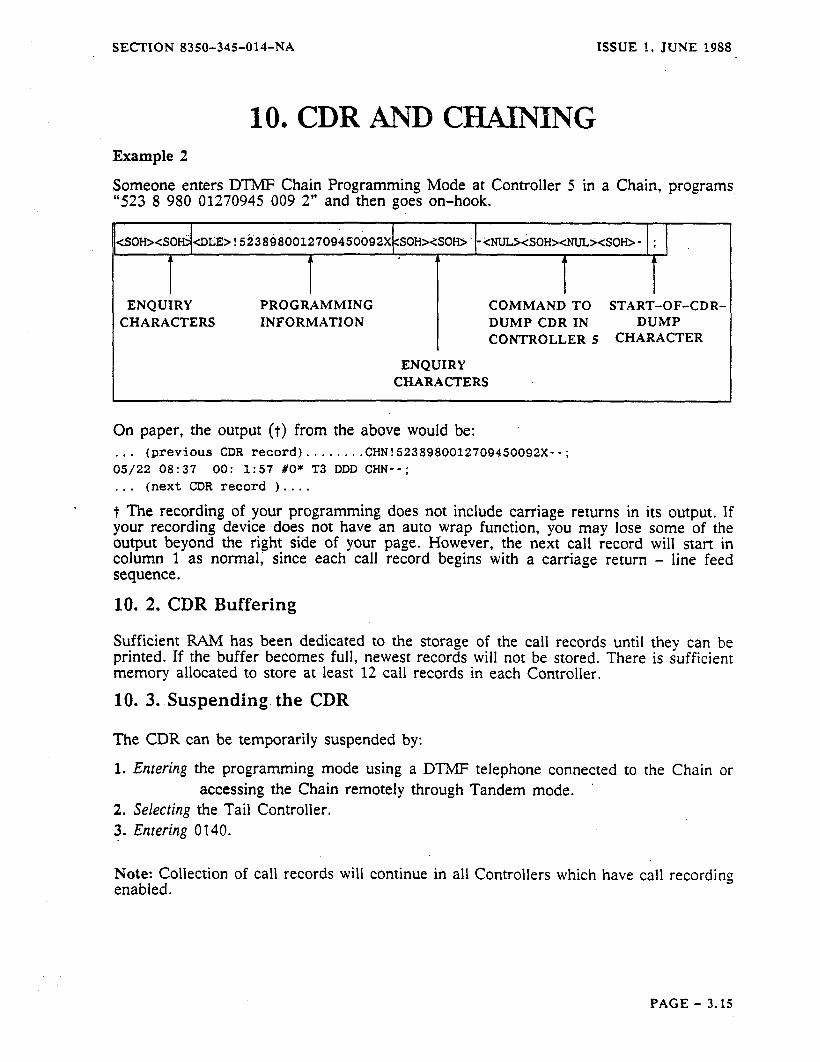
SECTION 8350-345-014-NA ISSUE 1, JUNE 1988
10. CDR AND CMNPNG Example 2
Someone enters DTMF Chain Programming Mode at Controller 5 in a Chain, programs “523 8 980 01270945 009 2” and then goes on-hook.
<DLE>!5i38$8~012709450092X SOH><SOH>‘-YNUL><SOH><NUL><SOH>- ;
T I
A
I I ENQUIRY PROGRAMMING COMMAND TO START-OF-CDR-
CHARACTERS INFORMATION DUMP CDR IN DUMP CONTROLLER 5 CHARACTER
ENQUIRY CHARACTERS
On paper, the output (t) from the above would be: . . . (previous CDR record)...... ..CHN!523898001270945Oo92x--; 05/22 08:37 00: 1:57 #0* T3 DDD CHN--: . . . (next CDR record I....
t The recording of your programming does not include carriage returns in its output. If your recording ‘device does not have an auto wrap function, you may lose some of the output beyond the right side of your page. However, the next call record will start in column 1 as normal; since each call record begins with a carriage return - line feed sequence.
10. 2. CDR Buffering
Sufficient RAM has been dedicated to the storage of the call records until they can be printed. If the buffer becomes full, newest records will not be stored. There is sufficient memory allocated to store at least 12 call records in each Controller.
10. 3. Suspending. the CDR
The CDR can be temporarily suspended by:
1. Entering the programming mode using a DTMP telephone connected to the Chain or accessing the Chain remotely through Tandem mode.
2. Selecting the Tail Controller. 3. Entering 0140.
Note: Collection of call records will continue in all Controllers which have call recording enabled.
PAGE - 3.15

ISSUE 1, JUNE 1988 SECTION 8350-345-01 d-N.4
10. .CDW AND CHAINING 10. 4. Enabling CDR
You can change Call Detail Recording (CDR) format as required: 0 The MITEL format was developed for PBX applications (specificaiiy MITEL PBXs).
Some fields are used..for call .transfers, ~attendants, eta, -and .are not supplied by the Controller.
l The MART format is similar to*the MITEL format, however it has reduced the printing width to fit in 80 columns and the R field is in ASCII instead of numeric.
For further information on the print format see APPENDIX 1 of MANUAL 2. The print format can be changed or disabled by:
REGISTER 009 DESCRIPTION DEFAULT
ENTER 009T T 0 FOR OFF T : 1 FOR MITEL PROVIDE A CARRIAGE
3 T = 2 FOR SMART RETURN LINE-FEED AT T = 3.f START OF RECORD
I I I I T = 5 FOR MITEL PROVIDE A CARRIAGE T = 6 FOR SMART RETURN LINE FEED T = 77 AT START OF RE-
CORD AND END
$ Note: Please go to your Manual 2 for an explanation of additional options for this pa- rameter.
PAGE - 3.16
SECTION 8350-345-014-NA ISSUE 1, JUNE 1988
11. CHAINING CONDITIONS Certain conditions and restrictions apply to Controllers and Chaining. This part outlines those restrictions under these headings:
Parameter 013 Parameter 014 Chains Other N&es
11. 1. Parameter 013
A Controller may be in one Chain only, and the Controller must have a unique ID as set by 013T.
The Controller must be programmed such that 013T is the same as the number you labeled the RS-232 connector, on the Chaining Cable. The Head Controller is always Controller number 1 in a Chain. (013&l). If 013T is set to anything ‘other than 0130 the RS-232. port can not be used for terminal programming.
11. 2. Parameter 014
Parameter 014T is always set to 0140 on each Controller, except on the Tail Controller, where it is set to the same value as 013T.
11. 3. Chains
The number of Controllers in a Chain must be exactly equal to the number of Controller ports in the Chaining Cable you are using(i.e. if you leave any of the Controller ports in the Chaining Cable open, or do not have a unit programmed as a Head, or do not have sequential ID numbers, it won’t work). Chains can not be hooked together. A Controller may be in one Chain only.
No Controller in a Chain may be programmed locally-from any device other than a DTMF source. The maximum number of Controllers in a Chain is 10.
The Controller in the Chain with the highest Controller number is always the Tail.
11. 4. Other Notes
When DTMF Chain Programming mode is first entered, all the Controllers are considered “selected” for the purpose of DTMF Chain Programming. User speed call programming and user PAV programming work around the Chain just as they do in a non-Chained Controller. If either is invoked, the software checks 013T to see if the Controller is in a Chain. If so, it automatically.sends the proper commands around the Chain. If not in a Chain, it doesn’t try to send the commands out to the RS-232 port. When setting up a Chain, program the Tail Controller with its 013T and 014T LAST. When taking down a Chain, take the Tail Controller out of the Chain FIRST by program- ming its 014 to 0, 013 to 0, 009 to 0, then do the others, then take the cable off.
PAGE - 3.17
* ISSUE 1, JUNE 1988 SECTION 8350-345-014-NX
11. CHAINING CONDITIONS It is not necessary to use DTMP Chain Programming if a Chaining Cable is connected to a Controller; “normal” DTMF programming may still be done for that Controller as before, if desired; only if command 950 is dialed will that Controller (and the rest of the Chain) enter the DTMF Chain Programming mode.
A printer is NOT necessary to perform DTMF Chain Pro&ramming;;If a printer is at- tached to the printer port of a Chaining Cable, DTMF Chain Programming activity will be shown on it.
The baud rate on the RS-232 port is defaulted to 1200 (006-T’ = 0064). Make sure that the printer or terminal you use is set to the same baud rate as you have set in 006T, and make sure that all the Controllers are set to the same baud rate when the Chaining Cable is attached.
’
You may use a terminal with a keyboard on the printer port of the Chaining Cable, but the keyboard will have no effect; this port is for a Receive Only device.
After a Chain is set up, it will stay set up even if the power to the Controllers is lost. Any CDR which had accumulated but had not yet printed out before the power outage is lost. Any call activity during the power outage, of course, generates no call records.
PAGE - 3.18
SECTION 8350-345-o 14-NA
INDEX
C CDR AND CI-iAINING, 3.14 CHAINING: CONDITIONS,- 3:17, 3-18 .:
CHAINING DATA VERIFICATION. 3.13
CDR buffering. 3.15
F FIGURE, 3.2
P Parameter 013, 3.17
Parameter 014, 3.17
S SETTING UP A CHAIN, 3.3
Suspending CDR. See CDR buffering
ISSUE 1, JUNE 1988
PAGE - 3.19
MlTEL ENGINEERING PRACTICE SECTlON MITL8350-047-l OO-lVA .’ Issue 2, May 1985
i ’
COMMON CARRIER ACCESk “PIALER
AND CALL CONTROLLER
GENERAL INFORMATION lh. ‘!’
0 - Copyright of MITEL DATACOM INC.‘1985 m TM - Trademark of MITEL DATACOM INC. :t.
, . i w - Registered Trademarksof MITEL CORPORATION ‘z;

SECTION MITL8350-047-IOO-NA
--- THIS PAGE INTENTIONALLY LEFT BLANK ---
SECTION MlTL8350-047-l OO-NA
NOTICE TO U.S. CUSTOMERS
The information contained in this document is believed to be accurate in all respects but is not warranted by MITEL DATACOM INC. The information is subject to change without notice and should not be construed in any way as a commitment by MITEL DATACOM INC. or any of its affiliates or subsidiaries. MITEL DATACOM INC. and its affiliates and subsidiaries assume no responsibility for any errors or omissions in this document. Revisions of this document or new editions of it may be issued to incorporate such changes.
WARNING
The SMarT- lTM Common Carrier Access and Call Controller generates, uses, and can radiate radio frequency energy and, if not installed and used in accordance with the instructions manual, may cause interference to radio communications. It has been tested and found to comply with the limits for a Class A computing device pursuant to Subpart J of Part 15 of FCC Rules, which are designed to provide reasonable protection against such interference when operated in a commercial environment. Operation of this equipment in a residential area is likely to cause interference, in which case the user, at his own expense, will be required to take whatever measures may be required to correct the interference.
Page i

SECTION MITL8350-047-l OO-NA
--- THIS PAGE INTENTIONALLY LEFT BLANK ---
._ i
_
i
.I
L
Page ii

SECTION MlTL8350-047-IOO-NA
NOTICE TO CANADIAN CUSTOMERS
The information contained in this document is believed to be accurate in all respects but is not warranted by MITEL DATACOM INC. The information is subject to change without notice and should not be construed in any way as a commitment by MITEL DATACOM INC. or any of its affiliates or subsidiaries. MITEL DATACOM INC. and its affiliates and subsidiaries assume no responsibility for any errors or omissions in this document. Revisions of this document or new editions of it may be issued to incorporate such changes.
WARNING
The Canadian Department of Communications label identifies certified equipment. This certification means that the equipment meets certain telecommunications network protec- tive, operational, and safety requirements. The Department does not guarantee that the equipment will operate to the user’s satisfaction.
Before installing this equipment, users should ensure that it is permissable to be connected to the facilities of the local telecommunications company. The equipment must also be installed using an acceptable method oc connection. In some cases, the company’s inside wiring associated with a single line individual service may be extended by means of a certified connector assembly (telephone extension cord). The customer should be aware that compliance with the above conditions may not prevent degradation of service in some situations.
Repairs to certified equipment should be made by an authorized Canadian maintenance facility designated by the supplier. Any repairs or alterations made by the user to this equipment, or equipment malfunctions, may give the telecommunications company cause to request the user to disconnect the equipment.
Users should ensure, for their own protection, that the electrical ground connections to the power utility, telephone lines, and internal metallic water pipe system, if present, are connected together. This precaution may be particularly important in rural areas.
CAUTION
Users should not attempt to make such connections themselves, but should contact the appropriate electric inspection authority, or electrician, as required.
The Load Number (LN) assigned to each terminal device denotes the percentage of the total load, to be connected to a telephone loop, that is used by the device to prevent overload- ing. The termination on a loop may consist of any combination of devices subject only to the requirement that the total of the Load Numbers of all of the devices doesn not exceed 100. An alphabetic suffix is also specified in the Load Number and designates the appro- priate ringing type (A or B), if applicable. For example, LN = 20 A designates a Load Number of 20 and an ‘A’ type ringer.
Page iii

SECTION MITL8350-047-l OO-NA
--- THIS PAGE INTENTIONALLY LEFT BLANK ---
Page iv

SECTION MITL8350-047-l OO-NA
IMPORTANT NOTES
Please note that MITEL DATACOM INC. has set up a National Field Service number for technical and installation assistance located in Dallas, Texas. This number is [214] 386-9400 for U.S. customers only (outside of normal working hours, a telephone answering service has been established for your convenience at this same number). For Canadian customers, please contact your local MITEL Regional Office.
The SMarT-lTM Dialer includes an on-board battery back-up system to prevent the loss of customer database. Besides protecting against loss of data during momentary power outages, this battery back-up should also provide sufficient memory retention to allow the Dialer to be programmed by the distributor and then transported to the cus- tomer’s site for installation. This battery back-up, however, is not intended for long storage periods and cannot be guaranteed to support memory for long periods of time.
As received from the factory, the Dialer battery is not guaranteed to have a full charge applied to it. In fact, the battery is likely to be only partially charged in view of the time in transit, and distributor storage time. No guarantee of any battery charge status can be made until the Dialer has been powered up for a period of time. A period of 24 hours is necessary to achieve a full charge on the battery.
Upon removal from its shipping carton, the Dialer should be powere.d up for a period of time and then “SC INITIALIZED” to load the operating system and default database into memory. Initialization may only be performed with a DTMF telephone set and requires connection to a working telephone line or an acceptable substitute. Never rely on program- ming entered into a Dialer until it has been “X INITIALIZED” (see Page 10, para. 3.05). Note that there is a short tone burst heard in the earpiece of the phone upon initialization. This tone indicates a successful initialize sequence has occurred.
Once initialized, the Dialer should seldom ever have to be initialized again. There is a “903” Load Default Data Command that will restore memory to the initialized state once a “X INITIALIZE” has been performed. Once initialized, the Dialer will also respond to input via the RS-232 Input.
REASONS FOR ADDITIONAL “x INITIALIZE” OPERATIONS
Dialer has just been removed from storage or shipping carton.
No toneburst upon release of the x Key. Maybe the tone was missed - check carefully.
The program access codes have been deleted accidentally or the access codes have been changed and forgotten.
The Dialer has just been repaired.
Long storage times.
Loss of data retention. Investigate for reason!
Page v

SECTION MITL8350-047-l OO-NA
--- THIS PAGE INTENTIONALLY LEFT BLANK ---
Page vi

SECTION MITL8350-047-l OO-NA
COWIMON CARRIER ACCESS DIALER AND CALL CONTROLLER
CONTENTS PAGE
1. INTRODUCTION ..................................... 1 GENERAL .......................................... 1 OVERVIEW OF THIS MANUAL .......................... 1 INTENDED AUDIENCE ................................ 1
2. GENERAL DESCRIPTION ............................... 3 FEATURES ......................................... 3 DEFINITION OF TERMS ............................... 3
Trunk Side Dialer ................................. 3 Store and Forward ................................ 4 User Transparent ................................. 4 Ground Start/Loop Start ........................... 4 DTMF/Rotary Dial ................................. 4 Power Failure Conditions ........................... 4 Area Code/Office Code/Call Searching ................ 5 Lines ............................................ 5 Two (2) Models Available ........................... 5 Adaptive Call Routing .............................. 5 Call Recording/RS-232 Port ......................... 5 Versatile Programming ............................. 5 Power .......................................... 6 Least Cost Routing ................................ 6 Speed Call ...................................... 6 Centrex Compatible ............................... 6
3.lNSTALLATlON ...................................... 7 INTRODUCTION ..................................... 7 UNPACKING ....................................... 7 MOUNTING ........................................ 7 CONNECTIONS ..................................... 7 SIMPLIFIED PROGRAMMING .......................... 10
Initializing the Dialer ............................. 10 Action on Dialing ................................ 10 Simplified OCC Programming ........................ 11
4.OPERATlON ....................................... 13 INTRODUCTION .................................... 13 GENERAL DESCRIPTION ............................. 13
Page vii
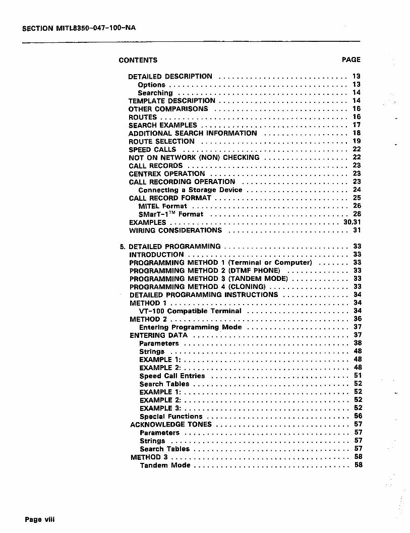
SECTION MlTL8350-047-l OO-NA
CONTENTS PAGE
DETAILED DESCRIPTION ............................. 13 Options ........................................ 13 Searching ...................................... 14
TEMPLATE DESCRIPTION ............................. 14 OTHER COMPARISONS .............................. 16 ROUTES .......................................... 16 SEARCH EXAMPLES ................................. 17 ADDITIONAL SEARCH INFORMATION ................... 18 ROUTE SELECTION ................................. 19 SPEED CALLS ..................................... 22 NOT ON NETWORK (NON) CHECKING ................... 22 CALL RECORDS .................................... 23 CENTREX OPERATION ............................... 23 CALL RECORDING OPERATION ........................ 23
Connecting a Storage Device ....................... 24 CALL RECORD FORMAT .............................. 25
MITEL Format ................................... 26 SMarT-lTM Format ............................... 28
EXAMPLES ...................................... 30,31 WIRING CONSIDERATIONS ........................... 31
5. DETAILED PROGRAMMING ............................ 33 INTRODUCTION .................................... 33 PROGRAMMING METHOD 1 (Terminal or Computer) ....... 33 PROGRAMMING METHOD 2 (DTMF PHONE) .............. 33 PROGRAMMING METHOD 3 (TANDEM MODE) ............. 33 PROGRAMMING METHOD 4 (CLONING) .................. 33 DETAILED PROGRAMMING INSTRUCTIONS ............... 34 METHOD 1 ........................................ 34
VT-100 Compatible Terminal ....................... 34 METHOD 2.. ...................................... 36
Entering Programming Mode ....................... 37 ENTERING DATA ................................... 37
Parameters ..................................... 38 Strings ........................................ 48 EXAMPLE 1: ..................................... 48 EXAMPLE 2: ..................................... 48 Speed Call Entries ............................... 51 Search Tables ................................... 52 EXAMPLEl: ..................................... 52 CI EXAMPLE 2: ..................................... 52 EXAMPLE 3: ..................................... 52 Special Functions ................................ 56
ACKNOWLEDGE TONES .............................. 57 Parameters ..................................... 57 Strings ........................................ 57 Search Tables ................................... 57
METHOD 3 ........................................ 58 Tandem Mode.. ................................. 58
Page viii
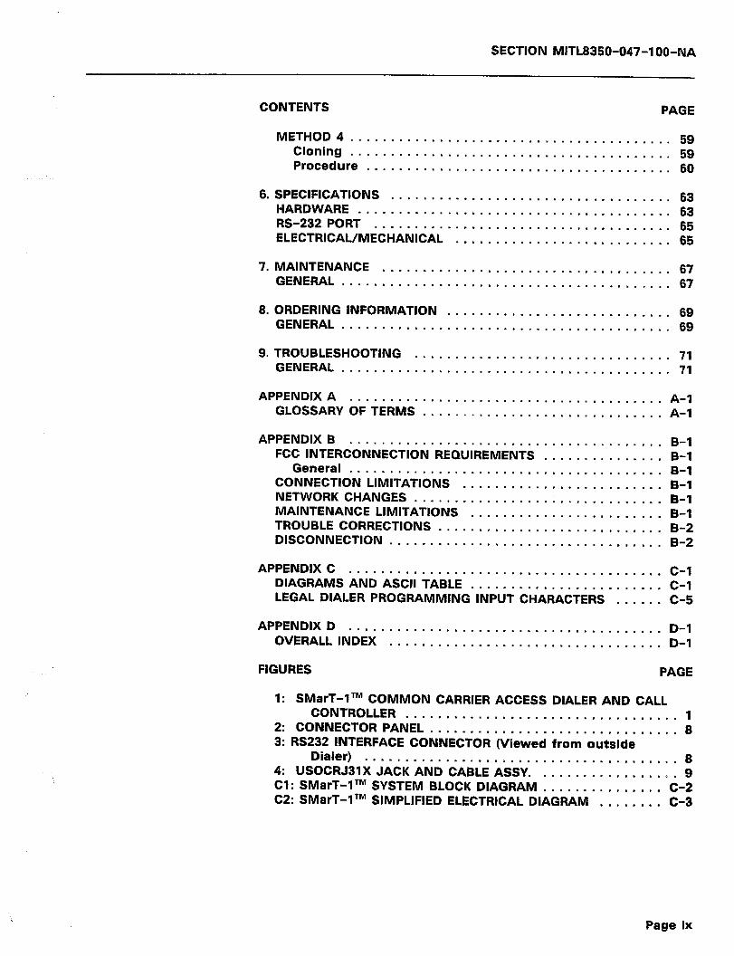
SECTION MITL8350-047-I 00-NA
CONTENTS PAGE
METHOD 4.. ...................................... 59 Cloning ........................................ 59 Procedure ...................................... 60
6. SPECIFICATIONS . . . . . . . . . . . . . . . . . . . . . . . . . . . . . . . . . . . 63 HARDWARE . . . . . . . . . . . . . . . . . . . . . . . . . . . . . . . . . . . . . . . 63 RS-232 PORT 65 ELECTRICAL/M&tklidd; ’ : : : : : : : : : : : : : : : : : : : : : : : : : : : 65
7. MAINTENANCE 67 GENERAL . . . . . . . . . . . . . . . . . . . . . . . . . . . . . . . . . . . . . . . . . 67
8. ORDERING INFORMATION ............................ 69 GENERAL ......................................... 69
9. TROUBLESHOOTING 71 GENERAL s........:::::::::::::::::::::::::::::::: 71
APPENDIX A ....................................... A-I GLOSSARY OF TERMS .............................. A-I
APPENDIX B ....................................... B-I FCC INTERCONNECTION REQUIREMENTS ............... B-I
General ....................................... B-I CONNECTION LIMITATIONS ......................... B-I NETWORK CHANGES ................. ; ............. B-I MAINTENANCE LIMITATIONS ........................ B-l TROUBLE CORRECTIONS ............................ B-2 DISCONNECTION .................................. B-2
APPENDIX C ....................................... C-I DIAGRAMS AND ASCII TABLE ........................ C-I LEGAL DIALER PROGRAMMING INPUT CHARACTERS ...... C-5
APPENDIX D ....................................... D-I OVERALL INDEX .................................. D-I
FIGURES PAGE
I: SMarT-ITM COMMON CARRIER ACCESS DIALER AND CALL CONTROLLER .................................. I
2: CONNECTOR PANEL ............................... 8 3: RS232 INTERFACE CONNECTOR (Viewed from outside
Dialer) ....................................... 8 4: USOCRJBlX JACK AND CABLE ASSY. ................. 9 CI : SMarT-ITM SYSTEM BLOCK DIAGRAM ............... C-2 C2: SMarT-ITM SIMPLIFIED ELECTRICAL DIAGRAM ........ C-3
Page ix
SECTION MITL8350-047-IOO-NA
TABLES PAGE
1: TEMPLATE DIGITS ............................... 15 2: ACTION DIGITS ................................. 15 3: ACCESS CONTROL SEQUENCE (ACS) CODES ........... 20 4a: DETECTOR/TIMEOUT (a) CODES .................... 21 4b: DETECTOR/TIMEOUT (b) CODES .................... 21 5: GENERAL PURPOSE STRINGS ....................... 22 6: MITEL CALL RECORD FORMAT FIELDS ................ 27 7: SMarT-1 TM CALL RECORD FORMAT FIELDS ............ 29 8: PARAMETERS ................................ 39-47 9: STRING DATA ENTRY .......................... 49-50 9a: DETECTOR/TIMEOUT (a) CODES .................... 50 9b: DETECTOR/TIMEOUT (b) CODES .................... 50 10: SPEED CALL ENTRIES ............................ 51 11: SEARCH TABLE ENTRIES ....................... 53-54 12: SPECIAL FUNCTIONS ............................. 57 13: SMarT-lTM HARDWARE SPECIFICATIONS ........... 63-64 14: RS-232 PORT SPECIFICATIONS ..................... 65 15: ELECTRICAL/MECHANICAL SPECIFICATIONS ........... 65 16: SMarT-1 TM ORDERING INFORMATION ................ 69 17: TROUBLESHOOTING CHART .................... 71-74 Cl:ASCllCODES .................................. C-4 C2: LEGAL DIALER PROGRAMMING CHARACTERS ......... C-5
.j
.
Page x
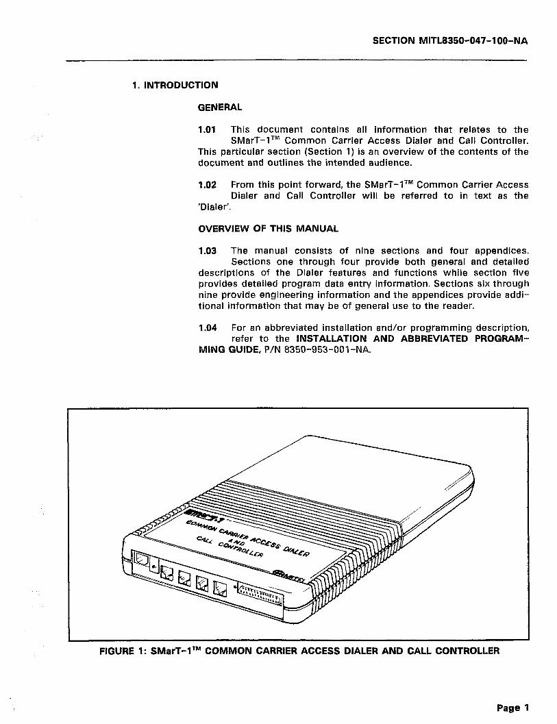
SECTION MlTLB350-047-l OO-NA
1. INTRODUCTION
GENERAL
1 .Ol This document contains all information that relates to the SMarT-lTM Common Carrier Access Dialer and Call Controller.
This particular section (Section 1) is an overview of the contents of the document and outlines the intended audience.
1.02 From this point forward, the SMarT-lTM Common Carrier Access Dialer and Call Controller will be referred to in text as the
‘Dialer’.
OVERVIEW OF THIS MANUAL
1.03 The manual consists of nine sections and four appendices. Sections one through four provide both general and detailed
descriptions of the Dialer features and functions while section five provides detailed program data entry information. Sections six through nine provide engineering information and the appendices provide addi- tional information that may be of general use to the reader.
1.04 For an abbreviated installation and/or programming description, refer to the INSTALLATION AND ABBREVIATED PROGRAM-
MING GUIDE, P/N 8350-953-001 -NA.
FIGURE 1: SMarT-lTM COMMON CARRIER ACCESS DIALER AND CALL CONTROLLER
Page 1

SECTION MlTL8350-047-l OO-NA
INTENDED AUDIENCE
1.05 This document is intended for use as a general reference docu- ment for the installer and user of the SMarT-lTM and SMarT-
lATM Common Carrier Access and Call Controller.
HISTORY
‘I.06 This is the second issue of the SMarT-lTM Common Carrier Access Dialer and Call Controller General Information Manual. It
replaces all manuals previously issued (Issue 1, March 1985). The reason for re-issue was to bring the manual up to the requirements of the present software level (GlO R05 and later) of the Dialer.
Page 2

SECTION MITL8350-047-l OO-NA
: : . . : : , .__: .‘.
2. GENERAL DESCRIPTION
FEATURES
2.01
0
0
0
0
l
0
e
0
0
l
l
l
l
The SMarT-lTM Common Carrier Access Dialer and Call Control- ler is a self-contained electronic unit that provides:
Compliance with FCC Parts 68 and 15
4 Line capacity for the SMarT-lTM unit
2 Line capacity for the SMarT-lATM unit
Call recording output
Call searching to select features
Versatile programming either locally, remotely, or limited
Automatic placement of selected calls through Other Common Carrier (OCC) facilities
Speed calling of up to 100 numbers, accessible by all users, unless denied on a trunk basis
Several convenience features:
l Useable with Centrex Lines 0 Useable behind a PBX l Can be configured as a hot line
Full tenant split that allows completely separate call screening patterns for two groups
Computer (RS-232) Input/Output port for either call recording or programming
Non-volatile memory
No loss of Memory during Power Failure
DEFINITION OF TERMS
2.02 The SMarT-lTM Dialer is a versatile unit, and as such, can ap- pear to be complex to the user. It is hoped that, with the
following explanations, it can be shown that the Dialer is indeed simple and versatile and that programming is quite simple. To further this concept, a glossary of terms and general information is included in the paragraphs below, that will familiarize the user with the terminology and ideas presented in this document.
2.03 For those who are interested in more complex uses of the Dialer, refer the last sections of this manual that detail com-
plete programming instructions and tables of codes.
_.. Page 3
SECTION MITL8350-047-l OO-NA
Trunk Side Dialer
2.04 The SMarT-1 fM Dialer is installed on the customer’s premises. The unit may be connected between any of the customer’s
equipment and the Central Office. When the customer’s Trunks/Lines are connected to the SMarT-lTM Dialer, all of the telephones within that system may (if selected) have access to their ‘Other Common Carrier’ (OCC)/Reseller’s Network, providing that they have access to those Trunks/Lines.
Store and Forward
2.05 The SMarT-lTM Dialer can be preprogrammed with the OCC/- Reseller’s access telephone number and the customer’s au-
thorization code. This eliminates the dialing of extra digits by the customer. It also provides a securitv factor, since the authorization code can be used on a ‘need to know’ basis. This information is ‘stored’ while programming. When the customer places a long distance call, it is dialed as normally done for a Direct Distance Dialing (DDD) call. The SMarT-lTM Dialer ‘forwards’ not only the long distance num- ber desired, but all of the ‘stored’ data to the OCC/Reseller’s system.
User Transparent
2.06 This term means that the user is unaware (hears nothing) of the ‘Store and Forward’ process because the routing is completed
with no pauses. However, there is an ‘ending tone’ that the caller will hear. This tone means that the Dialer has completed its routing through the system (Central Office to OCC/Reseller’s Switch).
Ground Start/Loop Start
2.07 These are the two types of Trunks/Lines that are available from a CO. The SMarT-lTM Dialer will function with either type.
DTMF/Rotary Dial
2.08 These are the types of dialing that are available. DTMF uses tones to dial while the Rotary system uses pulses. The SMarT-
lTM Dialer will operate with either type.
Power Failure Conditions w
2.09 In the event of a commercial power outage, the SMarT-lTM Dialer will assume a “power down cut-through mode”. In this
state, the Dialer appears to the network as a metallic path from its tip and ring inputs to the tip and ring outputs. Even though the telephone system may not be operational, the Dialer will not interfere with any telephone operations that may be available (i.e., incoming calls). The battery back up feature inherent in the Dialer allows the customers
Page 4
SECTION MlTL8350-047-‘l OO-NA
stored data to be retained. There is no requirement for reprogramming the Dialer once power is restored.
Area Code/Office Code/Call Searching
2.10 The SMarT-lTM Dialer can be programmed to ‘look up’ the Area Code (NPA) and Office Code (NXX) numbers and perform rout-
ing decisions (i.e., route through OCWReseller Switch, route DDD, or restrict) depending on the OCWReseller’s capabilities and the cus- tomer’s requests.
Lines
2.11 There are four independent lines in the Dialer. They all share the same search tables. Results of the searching will select a
route (in actuality, a ‘routing method’). The routing data (the four alternatives) is shared among the lines.
Two (2) Models Available
2.12 The SMarT-lTM Dialer services four independent telephone lines, while the SMarT-lATM services two lines. Both are com-
pact and powerful systems that provide simplified access to the com- mon carrier network. The calling side of the connection may be a telephone, key system line card, or a PBX trunk card. The called side of the connection may be a central office or a PBX line circuit. Operation may be completely transparent to the user.
Adaptive Call Routing
2.13 All calls are made over predetermined routes, with the required authorization codes and account codes being inserted auto-
matically by the Dialer at the appropriate time. The Adaptive Call Routing (ACR) feature allows the SMarT-lTM and SMarT-lATM to auto- matically detect, remember and re-route all numbers not available on the OCC over the DDD Network.
Call Recording/R%232 Port
2.14 The call recording output, via the computer (RS-232) port with programmable Baud rate, provides a complete record of num-
bers dialed and on-hook/off-hook times for all calls dialed on the lines served by the system. This information can be used by the Common Carrier or user for traffic studies, usage analysis, call costing, etc..
Versatile Programming
2.15 The Dialer requires some programming before use. Four pro- gramming options are provided which allow the installer to
choose the best method for the appropriate situation. Programming can be performed locally or remotely using a DTMF or butt-in station,
Page 5
SECTION MITL8350-047-l OO-NA
and is protected against unauthorized changes by a log-on access code. Programs can also be copied from one Dialer to another by simply interconnecting the systems. In addition, programming can be performed very quickly via the computer (RS-232) port, from selected lap or personal computers, using an available software package.
Power
2.16 Power is supplied from a small transformer provided with the system. Battery back-up prevents memory loss in the event of
power failure.
Least Cost Routing
2.17 This will allow alternate routing of long distance calls through various OCC facilities. Since toll calls placed through OCC net-
works are typically less expensive than DDD routes, choosing the most economical medium (i.e., DDD or whatever OCC) will enable the user to capitalize on OCC network rate benefits.
Speed Call
2.18 These are preprogrammed telephone numbers which allow the users to have the capability of simplified dialing. Up to 100
numbers can be stored in the Speed Call area and are accessible for all users. Speed dial telephone numbers are activated by dialing a three digit number. A limited program access code is provided to allow subscriber entry of speed dials.
Centrex Compatible
2.19 In this mode, the SMarT-I TM Dialer will recognize the ‘outside line’ access code (e.g., digit ‘9’) and will route all internal calls
transparently. In addition, the Dialer can be programmed to recognize certain area codes, and direct calls to those areas over an alternate route. This also provides Least Cost Routing capability.
Page 6
SECTION MITL8350-047-l OO-NA
3. INSTALLATION
INTRODUCTION
3.01 The word ‘Installation’ as used in this section means the elec- trical and mechanical connection to the wires of the user and
the associated Central Office along with simplified steps to place the unit into operation.
UNPACKING
3.02 The SMarT-lTM Dialer is packaged in a box along with the Power Supply and Mounting Bracket. Simply open the box and
remove the contents while checking for damage. Check the contents against the packing list. If any items are missing or appear to be defective, notify the vendor for further instructions.
MOUNTING
3.03 The SMarT-lTM Dialer is housed in a compact plastic enclosure that measures 10.625 inches (26.99cm) X 7.625 inches (19.37cm)
X 1.375 inches (3.49cm). The unit may be operated in any physical orientation, although wall-mount installation by use of the enclosed bracket is recommended. Simply mount the bracket to a surface with screws, and mount the Dialer housing to the bracket by matching the four holes on the rear of the case with the mounting pins of the bracket. Press into place.
CONNECTIONS
3.04 Seven connections are required for operation. These are made to the connectors located along one edge of the housing (refer
to Figure 2). Make the connections as follows:
1) Earth Ground MUST be connected to the screw mount provided on the bottom connector strip. The unit will not function prop- erly without this connection.
2) Power is fed to the Dialer via a three wire cord with jack from the accompanying Power Pack. Simply plug the cord of the Power Pack into the Dialer power jack. Plug the Power Pack AC Cord into a source of 11OV at 60 Hz (normal AC wall outlet).
3) Telephone signals are connected through four standard RJ31X non-shorting jacks. Four cables with appropriate connectors are supplied with the Dialer for this purpose. Insert one end of the supplied cable into each of the four jacks on the Dialer. The other end of this cable is to be connected to the Telco-supplied jack.
4) The last connection, which is optional, is an RS-232 female connector configured as “DCE”. Only the TxD (pin 3), the RxD
Page 7
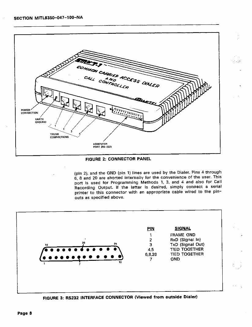
SECTION MITL8350-047-IOO-NA
FIGURE 2: CONNECTOR PANEL
(pin 2), and the GND (pin 1) lines are used by the Dialer. Pins 4 through 6, 8 and 20 are shorted internally for the convenience of the user. This port is used for Programming Methods 1, 3, and 4 and also for Call Recording Output. If the latter is desired, simply connect a serial printer to this connector with an appropriate cable wired to the pin- outs as specified above.
!JlJ SIGNAL
I FRAME GND 2 RxD (Signal In) 3 TxD (Signal Out)
495 TIED TOGETHER 6,8,20 TIED TOGETHER
7 GND
FIGURE 3: RS232 INTERFACE CONNECTOR (Viewed from outside Dialer)
Page 8
‘..’
.

PIN
1
SUB
R \
JACK
O
N C
ARD
IN
SID
E C
ASE
SHO
RTIN
G
BAR
r-----
-- /I
PIN
8 -
SU
B RI
NG
PIN
4 C
O R
-I
PIN
5
CO T
-
PIN
8
SUB
T
TO
RJ31
BO
X /’
/ PC
B ED
GE
NOTE
: BO
X TO
H
AVE
SHO
RTIN
G
BAR
S AL
SO,
PER
FCC
-----1
4 8
0 8El
7
In
6 m
5
-1
l m
4
_ Al
3
-l-
kl m
l 1
PLUG
, M
ECH
.
RJ31
JA
CK

SECTION MITL8350-047-l OO-NA
Initializing the Dialer
3.05 Before using the Dialer for the first time, it must be initialized by the procedure listed below. This provides the Dialer with
simple operating instructions. This data default base can be later modified by the customer if required, by the use of one of the methods outlined in the Detailed Programming section that appears at the end of this manual or by the simplified OCC programming in the following paragraph. The simplified programming procedure is:
l
1)
2)
3)
4)
5)
6)
3.06
With the RJ31 Cable connected:
Connect either a DTMF station or DTMF Butt-set unit to the subscriber Tip and Ring of Line 1 of the Dialer. For Butt-set units, the connections must be made external to the Dialer. If the Dialer is opened, the Warranty Seal will be broken, voiding the unit warranty. It is suggested that the Butt-set be con- nected at the Telco supplied connections.
With the DTMF station or butt-set off-hook, disconnect power from the Dialer.
While holding the % Key, reconnect the power.
Continue to hold’ the * Key down for 10 seconds or more. A tone should be audible in the earpiece of the handset.
When the x Key is released, the unit will acknowledge with a short tone burst that is audible in the earpiece of the handset. Default programming is now loaded and the Dialer is in the cut-through mode (no Dialer activity - digits are passed straight through the Dialer).
Go back On-hook.
The x23 parameter (see page 43) is used to ‘wake up’ the Dialer. To ‘wake up’ the Dialer, simply go off-hook. Enter the program
mode by dialing #OX. After dialing #OX, a beep should be heard in the receiver. Then dial 523 (wait for beep). Dial 8 (wait for two (2) beeps), then go on hook. The SMarT-1 TM Dialer is now configured as follows:
0 All Trunks are Loop Start.
l A single tone (or beep) is used to notify the user that the Dialer is functioning.
0 There are no Speed Call numbers.
a The Security Access Code is #OX from a DTMF telephone.
Action on Dialing
3.07 At this point, there are some default actions that will occur
Page 10
SECTION MITL8350-047-IOO-MA
when a number is dialed. The paragraphs that follow describe the action that will result when specific digits are dialed. These may be changed later when more detailed programming is accomplished. The paragraphs are structured by listing the dialed digits in bold at the beginning, followed by a description of the action taken by the Dialer.
3.08 1st Digit 0 and 2nd Digit 1: This indicates that the call is to an international destination, and, as such, the length or number of
digits to be dialed is not known. After the last desired digit is dialed by the user, the Dialer will wait for six seconds before assuming that dialing has been completed. The Dialer will also assume that dialing is completed if a “#” is dialed.
3.09 1st Digit 0 or 1, 3rd Digit 0 or 1: This indicates to the Dialer that the call destination is within North America, and, as such,
only eleven digits will be dialed. The Dialer assumes that the number is complete after the eleventh digit and does not wait for or recognize any further digits.
3.10 1st Digit 0 or 1, 3rd Digit NOT 0 or 1: This indicates to the Dialer that the call is a local area long distance call, and, as
such, only eight digits will be dialed. Once again, the Dialer assumes that the number is complete after the eighth digit and does not wait ,for more digits.
3.11 1st Digit NOT 0 or 1: This call is a local call and will be complete after the seventh dialed digit. The Dialer does not wait
for more digits.
3.12 911 and 1411: If these digits are dialed, the Dialer will assume that the call is complete after these digits. It will complete the
call on the DDD Network immediately.
3.13 All Other: The Dialer will wait for the timeout period of six seconds after the last digit is dialed before assuming that the
number is complete.
Simplified OCC Programming
3.14 The programming that follows is a simplified version for imme- diate change to the default data base loaded in paragraph 3.05
above. It ‘allows the Dialer to be programmed for general use with most OCWReseller systems. If the Dialer has never been used before, the steps outlined under paragraph 3.05 above must be accomplished. Then follow the steps listed below:
1) By using the DTMF station or Butt-set connected to the sub- scriber side of any Dialer trunk, go off-hook and dial the Secu- rity Access Code, #OX. A short tone will be sent to the earpiece of the handset (after the x is dialed) that indicates access to programming mode. Programming parameter entries will be punctuated with acknowledge tones.
Page 11
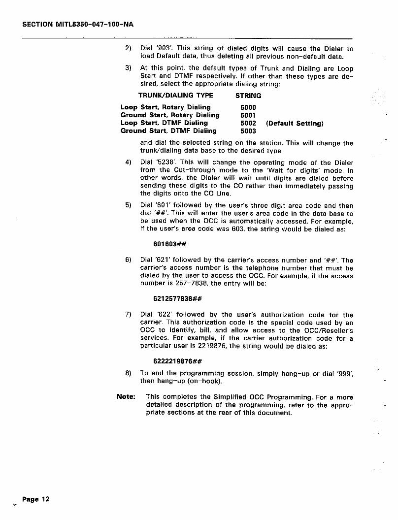
SECTION MITL8350-047-l OO-NA
2) Dial ‘903’. This string of dialed digits will cause the Dialer to load Default data, thus deleting all previous non-default data.
3) At this point, the default types of Trunk and Dialing are Loop Start and DTMF respectively. If other than these types are de- sired, select the appropriate dialing string:
TRUNK/DIALING TYPE STRING
Loop Start, Rotary Dialing 5000 Ground Start, Rotary Dialing 5001 Loop Start, DTMF Dialing 5002 (Default Setting) Ground Start, DTMF Dialing 5003
4)
5)
6)
7)
8)
and dial the selected string on the station. This will change the trunwdialing data base to the desired type.
Dial ‘5238’. This will change the operating mode of the Dialer from the Cut-through mode to the ‘Wait for digits’ mode. In other words, the Dialer will wait until digits are dialed before sending these digits to the CO rather than immediately passing the digits onto the CO Line.
Dial ‘601’ followed by the user’s three digit area code and then dial ‘##I. This will enter the user’s area code in the data base to be used when the OCC is automatically accessed. For example, if the user’s area code was 603, the string would be dialed as:
601603##
Dial ‘621’ followed by the carrier’s access number and ‘##‘. The carrier’s access number is the telephone number that must be dialed by the user to access the OCC. For example, if the access number is 257-7838, the entry will be:
6212577838##
Dial ‘622’ followed by the user’s authorization code for the carrier. This authorization code is the special code used by an OCC to identify, bill, and allow access to the OCC/Reseller’s services. For example, if the carrier authorization code for a particular user is 2219876, the string would be dialed as:
6222219876##
To end the programming session, simply hang-up or dial ‘999’, then hang-up (on-hook).
Note: This completes the Simplified OCC Programming. For a more detailed description of the programming, refer to the appro- < priate sections at the rear of this document.
Page 12
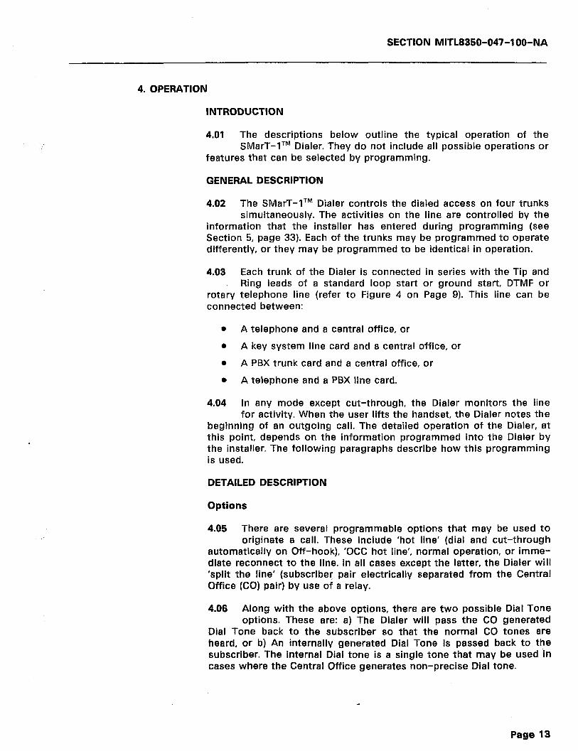
SECTION MITL8350-047-l OO-NA
4. OPERATION
INTRODUCTION
4.01 The descriptions below outline the typical operation of the SMarT-lTM Dialer. They do not include all possible operations or
features that can be selected by programming.
GENERAL DESCRIPTION
4.02 The SMarT-lTR” Dialer controls the dialed access on four trunks simultaneously. The activities on the line are controlled by the
information that the installer has entered during programming (see Section 5, page 33). Each of the trunks may be programmed to operate differently, or they may be programmed to be identical in operation.
4.03 Each trunk of the Dialer is connected in series with the Tip and Ring leads of a standard loop start or ground start, DTMF or
rotary telephone line (refer to Figure 4 on Page 9). This line can be connected between:
0 A telephone and a central office, or 0 A key system line card and a central office, or l A PBX trunk card and a central office, or
0 A telephone and a PBX line card.
4.04 In any mode except cut-through, the Dialer monitors the line for activity. When the user lifts the handset, the Dialer notes the
beginning of an outgoing call. The detailed operation of the Dialer, at this point, depends on the information programmed into the Dialer by the installer. The following paragraphs describe how this programming is used.
DETAILED DESCRIPTION
Options
4.05 There are several programmable options that may be used to originate a call. These include ‘hot line’ (dial and cut-through
automatically on Off-hook), ‘OCC hot line’, normal operation, or imme- diate reconnect to the line. In all cases except the latter, the Dialer will ‘split the line’ (subscriber pair electrically separated from the Central Office (CO) pair) by use of a relay.
4.06 Along with the above options, there are two possible Dial Tone options. These are: a) The Dialer will pass the CO generated
Dial Tone back to the subscriber so that the normal CO tones are heard, or b) An internally generated Dial Tone is passed back to the subscriber. The internal Dial tone is a single tone that may be used in cases where the Central Office generates non-precise Dial tone.
Page 13
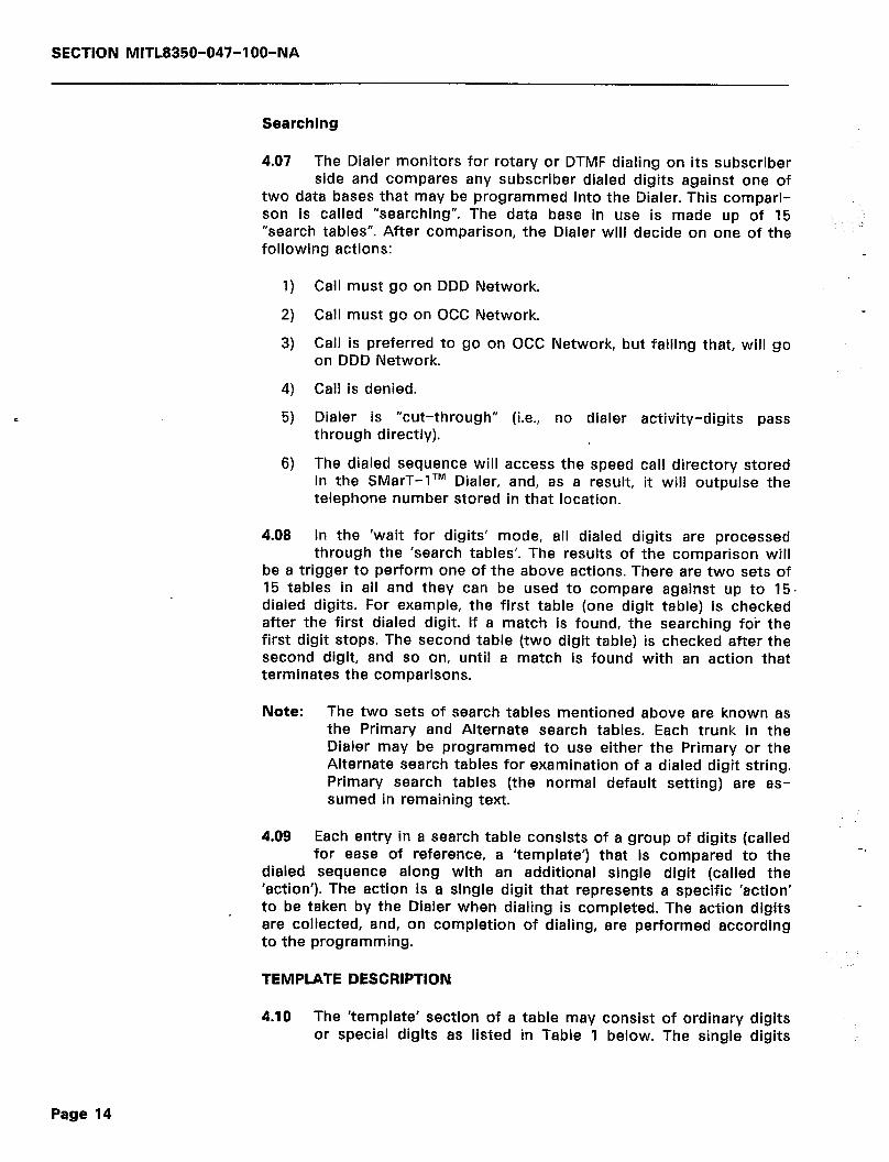
SECTION MITL8350-047-l OO-NA
Searching
4.07 The Dialer monitors for rotary or DTMF dialing on its subscriber side and compares any subscriber dialed digits against one of
two data bases that may be programmed into the Dialer. This compari- son is called “searching”. The data base in use is made up of 15 ,. “search tables”. After comparison, the Dialer will decide on one of the following actions: *
1) Call must go on DDD Network.
2) Call must go on OCC Network. -
3) Call is preferred to go on OCC Network, but failing that, will go on DDD Network.
4) Call is denied.
5) Dialer is “cut-through” (i.e., no dialer activity-digits pass through directly).
6) The dialed sequence will access the speed call directory stored in the SMarT-lTM Dialer, and, as a result, it will outpulse the telephone number stored in that location.
4.08 In the ‘wait for digits’ mode, all dialed digits are processed through the ‘search tables’. The results of the comparison will
be a trigger to perform one of the above actions. There are two sets of 15 tables in all and they can be used to compare against up to 15. dialed digits. For example, the first table (one digit table) is checked after the first dialed digit. If a match is found, the searching for the first digit stops. The second table (two digit table) is checked after the second digit, and so on, until a match is found with an action that terminates the comparisons.
Note: The two sets of search tables mentioned above are known as the Primary and Alternate search tables. Each trunk in the Dialer may be programmed to use either the Primary or the Alternate search tables for examination of a dialed digit string. Primary search tables (the normal default setting) are as- sumed in remaining text.
4.09 Each entry in a search table consists of a group of digits (called for ease of reference, a ‘template’) that is compared to the
dialed sequence along with an additional single digit (called the ‘action’). The action is a single digit that represents a specific ‘action’ to be taken by the Dialer when dialing is completed. The action digits are collected, and, on completion of dialing, are performed according to the programming.
-r
TEMPLATE DESCRIPTION
4.10 The ‘template’ section of a table may consist of ordinary digits or special digits as listed in Table 1 below. The single digits
Page 14
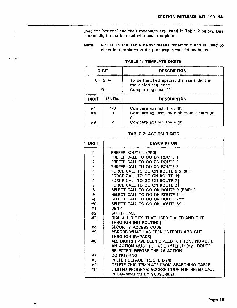
SECTION MITL8350-047-l OO-NA
used for ‘actions’ and their meanings are listed in Table 2 below. One ‘action’ digit must be used with each template.
Note: MNEM. in the Table below means mnemonic and is used to describe templates in the paragraphs that follow below.
TABLE 1: TEMPLATE DIGITS 7
DIGIT DESCRIPTION
o-9,* To be matched against the same digit in the dialed sequence.
#O Compare against ‘#‘.
DIGIT MNEM. DESCRIPTION
#l l/O Compare against ‘1’ or ‘0’. #4 n Compare against any digit from 2 through
9. #9 X Compare against any digit.
TABLE 2: ACTION DIGITS
DIGIT DESCRIPTION
0 1 2 3 4 5 6 7 8 9
lll #l #2 #3
#4 #5
#6
#7 #8 #9 #C
PREFER ROUTE 0 (PRO) PREFER CALL TO GO ON ROUTE 1 PREFER CALL TO GO ON ROUTE 2 PREFER CALL TO GO ON ROUTE 3 FORCE CALL TO GO ON ROUTE 0 (FRO)? FORCE CALL TO GO ON ROUTE IT FORCE CALL TO GO ON ROUTE 2jy FORCE CALL TO GO ON ROUTE 3T SELECT CALL TO GO ON ROUTE 0 (SRO)“ft SELECT CALL TO GO ON ROUTE l-F? SELECT CALL TO GO ON ROUTE 2Tt SELECT CALL TO GO ON ROUTE 3Tf DENY SPEED CALL DIAL ALL DIGITS THAT USER DIALED AND CUT THROUGH (NO ROUTING) SECURITY ACCESS CODE ABSORB WHAT HAS BEEN ENTERED AND CUT THROUGH (BYPASS) ALL DIGITS HAVE BEEN DIALED IN PHONE NUMBER. AN ACTION MUST BE ENCOUNTERED (e.g., ROUTE SELECTED) BEFORE THE #6 ACTION DO NOTHING PREFER DEFAULT ROUTE (x24) DELETE THIS TEMPLATE FROM SEARCHING TABLE LIMITED PROGRAM ACCESS CODE FOR SPEED CALL PROGRAMMING BY SUBSCRIBER
SECTION MITL8350-047-l OO-NA
Note: T These will force the call onto the selected route if possi- ble. If not possible, the call will not be completed. Redial and retry attempts will be directed to the same selected route.
TT These will not dial out the ‘select’ digits and will start comparisons over again from the first digit.
Dialer begins dialing out upon encountering any of the above search table actions with the exception of #I, #4 through #7, and #9.
OTHER COMPARISONS
4.11 In addition to comparing the dialed digits to the search tables, three other comparisons are made. The first digit dialed is
checked for a match against the Centrex Access digit. Every digit after the first dialed digit (prior to call completion) is checked to see if it is the ‘restart’ character (i.e., the restart character allows the user to start dialing again to correct mistakes). Lastly, after the Dialer has finished dialing, any further digits dialed by the user are compared to the ‘redial on Route #0’ and ‘redial on the same route’ digits. If a match occurs in this case, the call will be dropped and redialed while the telephone remains off-hook (i.e., the Dialer releases and re-seizes the line).
4.12 This allows extreme flexibility in the use of the Dialer. It also means that any mode of operation (other than the cut-through
mode on initialization) requires some programming.
ROUTES
4.13 The four routes (listed in Table 2) are called ROUTE #0 through ROUTE #3. These can be assigned either to the DDD Network or
the OCC Network. Each route can be selected by programming the search tables accordingly, and each has its own access method. For example, to access the DDD Network, the user waits for the dial tone and then dials. To access the OCC Network, the user would perform the following steps:
1) Wait for dial tone
2) Dial the ‘access code’ (OCC phone number)
3) Wait for further dial tone
4) Dial the ‘authorization code’
5) Dial the ‘destination number’ (called party)
4.14 All of the above steps can easily be associated with a route and dialed automatically by use of the access control sequences
(see 4.25).
Page 16

SECTION MITL8350-047-l OO-NA
SEARCH EXAMPLES
4.15 The following paragraphs describe the typical uses of the search tables when combined with routing data. Not all pos-
sibilities are discussed since programming is very flexible. This exam- ple presumes that Route #O is used for the DDD Network and Route #1 is used for the OCC private carrier.
4.16 The examples associated with these descriptions list the digit to be entered in the template, followed by the action and a
description. Digit definition and mnemonic use in the examples is defined in Tables 1 and 2 above.
EXAMPLE 1: 1+ CALLS TO CARRIER
TEMPLATE ACTION DESCRIPTION
1 5 (FRl) Any call starting with digit 1 will be forced. onto Route #I.
X 4 (FRO) Don’t care; any other first digit will force the call onto Route #O
4.17 In the example above, FRl (Force on Route #I) is selected over PRl (Prefer Route #l) so that if the call fails (say, due to an
OCC network problem), the call can only be retried on the same route. The retry is directed to another route only when the ‘action’ used is PRl.
EXAMPLE 2: l+ CALLS TO CARRIER, 1+800 TO DDD
TEMPLATE ACTION DESCRIPTION
1800 4 (FRO) This is the fourth digit search table. All I+800 calls will go on the DDD Network.
1 xxx 5 (FRl) All other I+ calls will go on Route #l (OCC).
xxxx 4 (FRO) After the fourth digit, any oth- er call will go on the DDD.
4.18 The Dialer makes a pass through the search tables after every digit. Once it finds an explicit match, it stops. Therefore, the
entry “1 x x x” stops the search before it arrives at the “x x x x” case. Notice that, in the example above, the Dialer holds off dialing until the fourth digit IN ALL CASES. To cause the Dialer to begin dialing after the first digit of a non l+ call, example 3 below would have to be pro- grammed.
Page 17
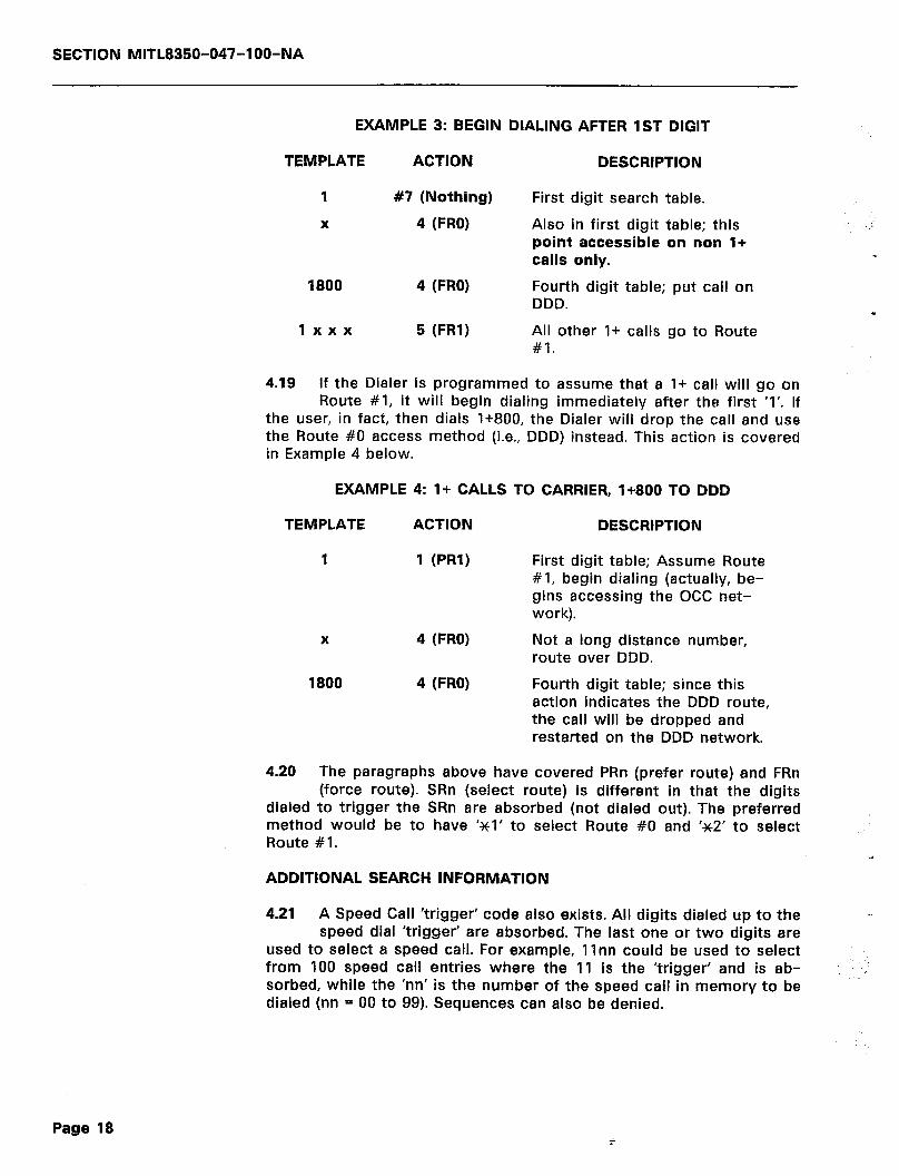
SECTION MITL8350-047-l OO-NA
EXAMPLE 3: BEGIN DIALING AFTER 1ST DIGIT
TEMPLATE ACTION DESCRIPTION
1 #7 (Nothing)
X 4 (FRO)
1800 4 (FRO)
First digit search table.
Also in first digit table; this point accessible on non l+ calls only.
Fourth digit table; put call on DDD.
1 xxx 5 (FRl) All other I+ calls go to Route #I.
4.19 If the Dialer is programmed to assume that a I+ call will go on Route #I, it will begin dialing immediately after the first ‘1’. If
the user, in fact, then dials 1+800, the Dialer will drop the call and use the Route #O access method (i.e., DDD) instead. This action is covered in Example 4 below.
EXAMPLE 4: l+ CALLS TO CARRIER, 1+800 TO DDD
TEMPLATE ACTION DESCRIPTION
1 1 (PRl) First digit table; Assume Route #I, begin dialing (actually, be- gins accessing the OCC net- work).
X 4 (FRO) Not a long distance number, route over DDD.
1800 4 (FRO) Fourth digit table; since this action indicates the DDD route, the call will be dropped and restarted on the DDD network.
4.20 The paragraphs above have covered PRn (prefer route) and FRn (force route). SRn (select route) is different in that the digits
dialed to trigger the SRn are absorbed (not dialed out). The preferred method would be to have ‘~1’ to select Route #0 and ‘~2’ to select Route #I.
ADDITIONAL SEARCH INFORMATION
4.21 A Speed Call ‘trigger’ code also exists. All digits dialed up to the speed dial ‘trigger’ are absorbed. The last one or two digits are
used to select a speed call. For example, 1 Inn could be used to select from 100 speed call entries where the 11 is the ‘trigger’ and is ab- sorbed, while the ‘nn’ is the number of the speed call in memory to be dialed (nn = 00 to 99). Sequences can also be denied.
Page 18
SECTION MlTL8350-047-l OO-NA
4.22 The entry in Table 2 on page 15 for digit ‘#6’ called ‘ALL DIGITS DIALED’ causes an action that tells the Dialer that the user has
finished dialing the called party, is ready to dial the ‘account code’, etc. Before encountering the #6, a previous search table must have se- lected a route and thus activated an Access Control Sequence (ACS).
4.23 There are two exception actions. These are the ‘cut-through’ and ‘do nothing’ action digits. The ‘cut-through’ does exactly as
it says. Whatever dialing is taking place finishes. The line is then reconnected. Screening stops at the search table containing the ‘cut-through’ action (#3) and no Access Control Sequence is used. This action will quite often result in incompleted calls as only a few digits may have been dialed. It is not recommended for general use. The ‘dial and cut-through‘ action will cause the SMarT-lTM to begin dialing, reproducing the user dialed digits until it catches up with the last entry dialed, and then cut through. This method will access the DDD Network in most ap’plications and may be used instead of the Route #0 in the above examples. However, once a call has been made in this manner, it may not be redialed. ‘The method is not recom- mended for Centrex applications, or applications that require redialing or DTMF to rotary conversions.
4.24 The ‘do nothing’ action allows the building of templates that match to any digit. This action stops the searching process
until the next digit.
ROUTE SELECTION
4.25 There are six groups of data that control the route selection (or define the access method). These consist of the destination,
access, authorization, account, Centrex numbers, and the Access Con- trol Sequence (ACS). These are defined as:
1)
2)
3)
4)
5)
6)
DESTINATION NUMBER: The destination number is the called party number and is dialed by the user (1 to 23 digits).
ACCESS NUMBER: This is the telephone number of the OCC, and is dialed by the SMarT-lTM unit (1 to 34 digits).
AUTHORIZATION NUMBER: The authorization number is the user’s special code for access to the Carrier services and is dialed by the Dialer (1 to 34 digits).
ACCOUNT NUMBER: The account number may be used to identify the calling party and is also dialed by the user (1 to 23 digits).
CENTREX NUMBER: The Centrex number is the sequence usu- ally used to access the desired Centrex service (1 to 34 digits).
ACCESS CONTROL SEQUENCE (ACS): The ACS is a sequence of codes that instruct the Dialer on the details of accessing a particular route. These details include such items as ‘what to dial first’, ‘when to wait for dial tone’, etc.. The codes and their
Page 19
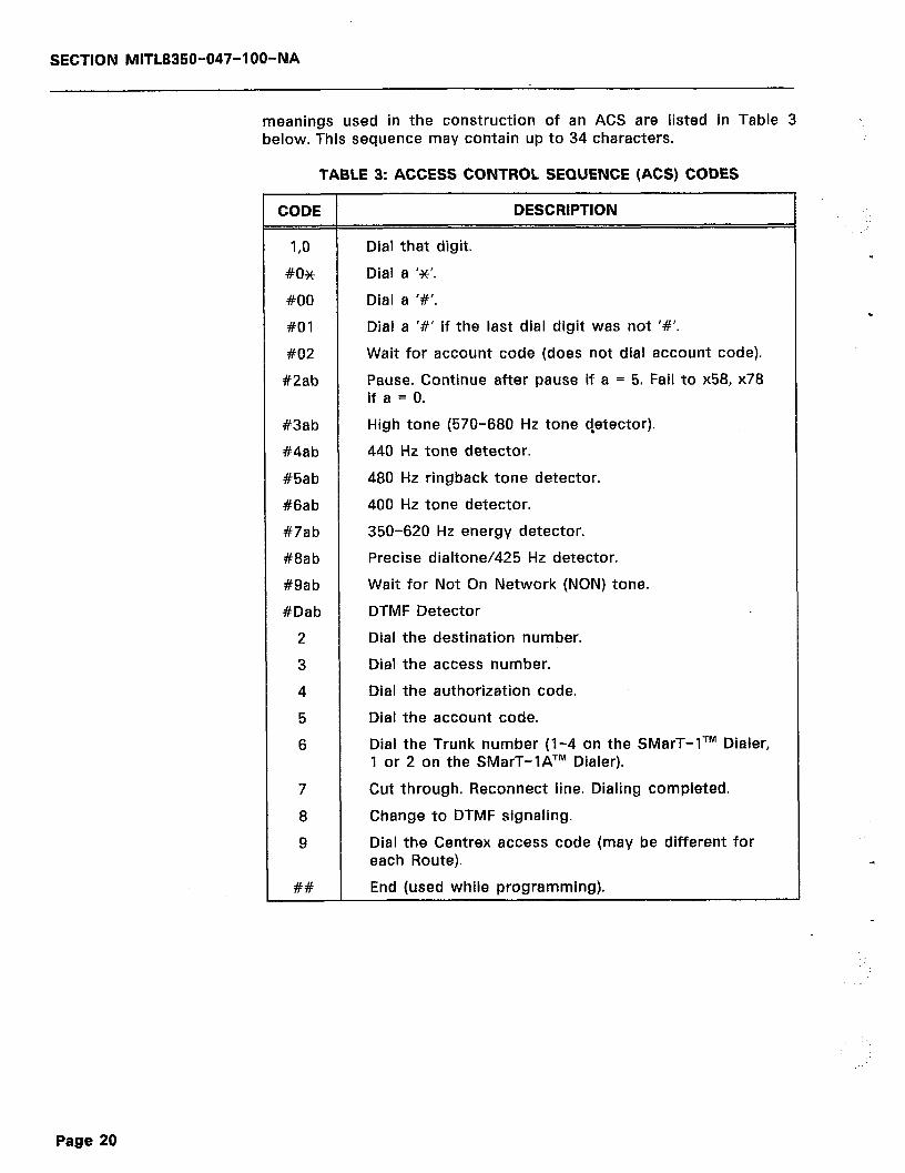
SECTION MITL8350-047-l OO-NA
meanings used in the construction of an ACS are listed in Table 3 below. This sequence may contain up to 34 characters.
TABLE 3: ACCESS CONTROL SEQUENCE (ACS) CODES
CODE
I,0
#O*
#OO
#Ol
#02
#2ab
#3ab
#4ab
#5ab
#6ab
#7ab
#8ab
#gab
#Dab
2
3
4
5
6
7
8
9
##
DESCRIPTION
Dial that digit.
Dial a ‘x’.
Dial a ‘#‘.
Dial a ‘#’ if the last dial digit was not ‘#‘.
Wait for account code (does not dial account code).
Pause. Continue after pause if a = 5. Fail to x58, x78 if a = 0.
High tone (570-680 Hz tone qetector).
440 Hz tone detector.
480 Hz ringback tone detector.
400 Hz tone detector.
350-620 Hz energy detector.
Precise dialtone/ Hz detector.
Wait for Not On Network (NON) tone.
DTMF Detector
Dial the destination number.
Dial the access number.
Dial the authorization code.
Dial the account code.
Dial the Trunk number (l-4 on the SMarT-lTM Dialer, 1 or 2 on the SMarT-lATM Dialer).
Cut through. Reconnect line. Dialing completed.
Change to DTMF signaling.
Dial the Centrex access code (may be different for each Route).
End (used while programming).
Page 20
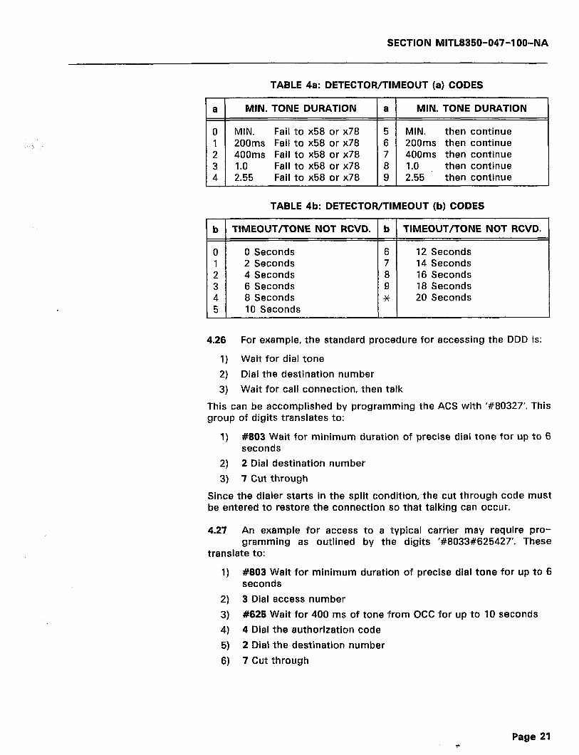
SECTION MITL8350-047-IOO-NA
TABLE 4a: DETECTOR/TIMEOUT (a) CODES
a MIN. TONE DURATION a MIN. TONE DURATION
0 MIN. Fail to x58 or x78 5 MIN. then continue 1 200ms Fail to x58 or x78 6 200ms then continue 2 400ms Fail to x58 or x78 7 400ms then continue 3 1.0 Fail to x58 or x78 8 1.0 then continue 4 2.55 Fail to x58 or x78 9 2.55 then continue
TABLE 4b: DETECTOR/TIMEOUT (b) CODES
b TIMEOUT/TONE NOT RCVD. b TIMEOUT/TONE NOT RCVD.
0 0 Seconds 6 12 Seconds 1 2 Seconds 7 14 Seconds 2 4 Seconds 8 16 Seconds 3 6 Seconds 9 18 Seconds 4 8 Seconds * 20 Seconds 5 10 Seconds
4.26 For example, the standard procedure for accessing the DDD is:
1) Wait for dial tone 2) Dial the destination number 3) Wait for call connection, then talk
This can be accomplished by programming the ACS with ‘#80327’. This group of digits translates to:
1) #803 Wait for minimum duration of precise dial tone for up to 6 seconds
2) 2 Dial destination number 3) 7 Cut through
Since the dialer starts in the split condition, the cut through code must be entered to restore the connection so that talking can occur.
4.27 An example for access to a typical carrier may require pro- gramming as outlined by the digits ‘#8033#625427’. These
translate to:
1) #803 Wait for minimum duration of precise dial tone for up to 6 seconds
2) 3 Dial access number 3) #625 Wait for 400 ms of tone from OCC for up to 10 seconds 4) 4 Dial the authorization code 5) 2 Dial the destination number 6) 7 Cut through
i Page 21

SECTION MITL8350-047-1 OO-NA
The arrangement above allows for all sorts of combinations. In order to appreciate the range of possibilities, the five strings that can be dialed are named to coincide with typical applications. These names are really general purpose and have the properties as outlined in Table 5 below.
TABLE 5: GENERAL PURPOSE STRINGS/NUMBERS
STRING
DESTINATION
ACCOUNT
ACCESS
AUTHORIZATION
CENTREX
PROPERTY
First digits dialed by the user; passed through the search tables.
Second item dialed by the user; can be substituted; can hold up dialing.
Entered at programming time.
Entered at programming time.
Entered at programming time.
4.28 It is evident that these strings can be assembled in any order in the ACS. They do not have to function in the manner that their
titles suggest. For instance, a private carrier network requires an au- thorization code of 1234~~x5678, where the xxx is a code entered by the user to identify the account. 1234 could be assigned to the au- thorization string, 5678 to the Centrex string, and the route pro- grammed to accept a three digit fixed length account code. Then part of the ACS would be programmed with ‘459’ that translates to ‘Dial authorization, dial account, and dial Centrex’.
SPEED CALLS
4.29 The speed call entries have two associated parameters. These are the key and the route override. The key is a single digit that
can selectively block dialing to any line. Note that all lines share the same speed call directory, and that any lines can be blocked from dialing any speed call number. The route override can force the call onto any of the four routes, or process the call through the search tables, or force the call to go out without any route selection (transparent).
NOT ON NETWORK (NON) CHECKING
4.30 Some networks return specific tones if the number requested is ‘Not on Network’. The ACS has a programmable parameter that,
if set, will make the Dialer wait for the programmed number of sec- onds, and, if a tone is detected, the call will be dropped. The destina- tion number will then be dialed using the Route #0 access method. In addition, the destination string is automatically entered in the search tables as FRO (Force Route 0), along with an expiry date tag. The date tag can be from 0 to 90 days in increments of ten days. Once
Page 22
SECTION MITL8350-047-l OO-NA
entered, all entries in the search tables that have expiry tags are decremented at midnight. Those tags that return to zero on decrement are cancelled. This means that, after the programmed number of days, the search tables would return to their original state.
4.31 There is no parameter in the programming that controls DTMF to pulse conversion. if the Central Office type is programmed as
rotary dialing, then any route access will start the call with rotary dialing. The ACS can have a ‘change to DTMF’ code that will instruct the Dialer that the signalling to the private carrier is to be performed in DTMF. Calls that have been ‘cut-through’ or ‘dial and cut-through’ due to a searching action will not perform DTMF to pulse conversion.
4.32 Paragraphs 4.30 and 4.31 illustrate why Route #0 is recom- mended for use in accessing the DDD Network.
CALL RECORDS
4.33 Every time a call is terminated, the Dialer will output a call record to the Computer (RS-232) port. This output consists of a
string of ASCII characters that describe the call. The format for the output is fixed so that the port can be connected to either a printer or to an external processor. The latter can use the data to generate statistics or call costing data. The printout can label the routes that are selected by using the appropriate programming.
CENTREX OPERATION
4.34 If the Centrex access digit is programmed, the Dialer will red- ognize the ‘outside line’ access code, routing all internal calls
transparently. Note that all of the ACSs should be programmed to include the ‘dial the Centrex’ code. Each route has a separate Centrex string that would allow one to access WATS or FX groups, instead of regular trunks.
CALL RECORDING OPERATION
4.35 The SMarT-lTM Common Carrier Access Dialer and Call Control- ler can easily be programmed to send a printable call record to
a variety of electronic storage devices. The call record indicates the originator of the call, the call duration, the dialed numbers, and other data.
THIS CALL RECORD SHOULD NOT BE CONSIDERED A
PERFECT RECORD OF THE CALL, NOR SHOULD IT BE CONSIDERED AS A LEGAL ENTITY. THERE ARE MANY CASES IN WHICH THE CALL RECORD PRODUCED BY THE SMarT-1 TM DIALER MAY DIFFER FROM THAT PRODUCED BY THE OCC.
Page 23
SECTION MITL8350-047-l OO-NA
Connecting a Storage Device
4.36 TERMINAL: Almost any CRT or paper-based (e.g., Silent 7OOT or Brother+/+) terminal may be connected to the SMarT-lTM unit.
Using a terminal as a storage device also has the extra advantage in that the terminal keyboard may be used to program the Dialer (refer to Programming Section). When connecting the terminal, the user should be aware that the Dialer is wired as a DCE, so that a normal RS-232 Cable can be used. Refer to the WIRING CONSIDERATIONS on page 30. Telephone digit programming may be used to select the Baud rate and other features. For example, 300 Baud can be chosen as the Dialer operating rate by entering the following from any line of the Dialer:
GO OFF-HOOK, THEN DIAL:
#Ox To enter programming mode. 0062 To select 300 Baud. 999 To exit programming.
Note: Once the default data has been loaded, the Dialer is automati- cally set for 1200 Baud.
4.37 PRINTER: Almost any serial printer may be connected to the Dialer. The printer allows the user to maintain a permanent
(depending on amount of paper) record of the calls placed through the Dialer. Connection of the printer is made via normal RS-232 Cable to the same port that may be used for a terminal. The Dialer must be programmed for the printer baud rate desired. This is accomplished by using one of the four Dialer programming methods.
4.38 Some printers require a modified data stream to handle excep- tions (such as Line Feed). There are three main techniques that
are used to modify the data stream. These are:
1) The printer may manipulate the Clear to Send (CTS) and Data Terminal Ready (DTR) wires.
Note: Method 1) above will not work with the SMarT-lTM Dialer. See WIRING CONSIDERATIONS on page 31.
2) The printer may transmit XOFF (DC3) to stop the data source, and XON (DCI) to restart the data source. The Dialer accepts this protocol and requires no additional programming to enable this feature.
3) The SMarT-lTM Dialer may be configured to add a variable number of NULLS (no character spaces) after the carriage return function, anticipating the time required by the printer. Use Pro- gram parameter 007n to enter the required number of nulls.
. . .
j- Silent 700 is a Trademark of Texas Instruments Brother is a Trademark of Brother International Corp.
Page 24
SECTION MITL8350-047-IOO-NA
Note: The XONIXOFF feature is provided to cover cases where the printer must slow the data stream down to handle functions such as carriage returns and line feeds. It is not intended for use in handling “paper out” and “off line” pauses. The print buffer that is on board the Dialer contains only three call records at any one time. The size of this buffer is adequate for most slow speed printers. It is not adequate for storing data during long pauses such as may arise when the paper runs out on the printer.
4.39 CALL COSTING UNIT: Most of the call costing units are nothing more than modified personal computers that estimate the cost
of the calls made. Some of these units also provide statistics on traffic. If the software of the Call Costing Unit is compatible, the Dialer may be connected to the unit via a normal RS-232 cable. If the unit has multiple inputs, multiple Dialers may be connected.
4.40 CONCENTRATOR: If a site has a lot of Dialers, it may be eco- nomical to funnel the output of several Dialers through an
electronic “concentrator” into a single printer or call costing unit for call recording.
4.41 When using a concentrator, the call record from each Dialer must be made to appear individual or different. String 602n can
be programmed (using ASCII Codes) to print a unique three character field for each Dialer. For example, Dialer #I at a site may be pro- grammed:
602 202331##
which will cause the printer to print “#I” at the end of each line. The second Dialer may then be programmed:
602 202332##
which will cause the number “#2” to be printed at the end of each line. The three character field set by 602 is printed in both the MITEL Format and SMarT-lTM Format discussed below.
Note: If the Dialers are programmed using the “cloning” technique, ensure that 602 is modified after cloning. If not, the Clone Master and the Clone Slave will have the same “name”.
CALL RECORD FORMAT
4.42 The Dialer can print call records in one of two formats. These formats are the MITEL Format and the SMarT-lTM Format. Se-
lection of the appropriate format is made by programming 009n. The MITEL Format is very similar to the call record that was pioneered by MITEL Inc. for use in its line of small PABXs. The call record is up to 86 characters in length and includes all of the information about a call.
Page 25

SECTION MITL8350-047-IOO-NA
The SMarT-lTM Format is a new format that was developed specifically for this product. It summarizes the call completely within 80 columns and provides an easy to read printout. In either case, the call record will show the digits that are dialed by the user and not the dialer- assembled digits as in an Access Control Sequence.
MITEL Format
4.43 Since this format was developed for use in PABX applications, a
there are fields that only pertain to transferred calls. The SMarT-lTM has no use for this information and, as a result, these fields are left blank. Otherwise, the format is very similar to the call record produced by IvlITEL PABXs.
4.44 Several call costing machines can process the original MITEL Format. For more information on tested systems, call MITEL.
The record is 86 characters long with the following fields:
M - Month/Day B - Start time (BBBB means that the clock is wrong)
(Note the period instead of a colon) C - Call duration Ill1 - Incoming line D - User dialed digits T - Denied S - Speed dialed L - Line number R - Route (8 = Internal in Centrex mode) A - Account code N - System identification
The above named fields are printed in a line as below:
MM/MM BB:BB Cc:Cc:CC 1111 DDDDDDDDDDDDDDDDDDDDDDD TSLLRR - NNN
where the fields are as described in Table 6:
4.45 Each line is ended with a CARRIAGE RETURN (ASCII 13) and LINE FEED (ASCII 10) and a programmable number of NULLS
(ASCII 0). All alphabetic fields are in upper case. The dialed number and the dialed account code fields will be numbers 0 through 9, * and #.
.
Page 26
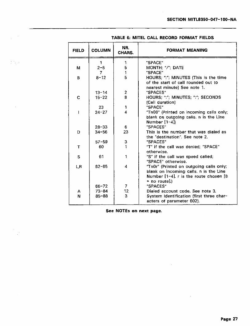
SECTION MITL8350-047-l OO-NA
TABLE 6: MITEL CALL RECORD FORMAT FIELDS
FIELD COLUMN NRm CHARS. FORMAT MEANING
1 1 “SPACE” M 2-6 5 MONTH; “I’; DATE
7 1 “SPACE” B 8-12 5 HOURS; ‘Y’; MINUTES (This is the time
of the start of call rounded out to nearest minute) See note 1.
13-14 2 “SPACES’ C 15-22 8 HOURS: ‘Y’; MINUTES; “:“; SECONDS
(Call duration) 23 1 ‘SPACE”
I 24-27 4 “TnOO” (Printed on incoming calls only; blank on outgoing calls. n is the Line Number [l-4])
28-33 6 “SPACES’ D 34-56 23 This is the number that was dialed as
the “destination”. See note 2. 57-59 3 ‘SPACES”
T 60 1 “T” if the call was denied; “SPACE” otherwise.
S 61 1 “S” if the call was speed called; “SPACE” otherwise.
L,R 62-65 4 “TnOr” (Printed on outgoing calls only; blank on incoming calls. n is the Line Number [‘l-4]. r is the route chosen 18 = no route].)
66-72 7 “SPACES” A 73-84 12 Dialed account code. See note 3. N 85-88 3 System Identification (first three char-
acters of parameter 602).
See NOTES on next page.
Page 27

SECTION MITL8350-047-IOO-NA
Note:l. Time Display Field: If the separating character in the start of call field is a period (.), the time has not been programmed into the Dialer. Use parameter 980 to program the time. When a Dialer is powered on, it will continue to use the last time that was programmed (time at power down) but will mark the call record with a period (J. If the loss of power is only a few seconds, it will not significantly affect the timekeeping.
.:
Note:P. Dialed Number Field: This field contains the phone number that was dialed as the “destination”. The number of digits in this field will be set by: 1) The search tables. If a #6 action (“enough digits”) is encountered, the “destination buffer” is marked as full. Only those digits so far received will be print- ed, or 2) An inter-digit timeout. If the user pauses while dialing, exceeding the inter-digit pause time, the “destination buffer” is marked as full. Only those digits received so far will be dialed.
If there is further dialing, these digits may be collected in the “account code”. If Centrex mode is being used, the user- dialed Centrex Access Code (usually a “9”) is not printed. The way to tell internal calls from external calls is to look at the route character (O-7 means a route was used, which probably dialed another “9” for the user; 8 means that the call was not routed, and the Dialer only forwarded the digits as displayed).
If a speed call is accessed, the speed call number will appear in this field. The sequence that was dialed to get the speed call (i.e., *cl 1) is NOT displayed. Denied calls are marked with a 7” in column 59.
Note:l. Dialed Account code: This field shows the digits that were dialed by the user for the account code. If the Dialer substi- tuted a “dummy account code”, this field still shows the user- dialed digits (not the “dummy”). It can be told by the number of digits that the “dummy” was substituted. This is done intentionally to allow monitoring for account code fraud at- tempts.
Only the first 12 digits are displayed, even though the SMarT- lTM unit can handle 23 digit account codes.
SMarT-lTM Format
4.46 Most of the explanations noted above also apply to the SMarT- lTM Format with the exception that the “R” field is in ASCII
instead of Numeric. The format was developed to allow the printing to fit within 80 columns and to take advantage of the ability of the Dialer to print ASCII (see note 4 below). A typical line entry would appear as:
MM/MM BBS6 GC:CC:CC DDDDDDDDDDDDDDDDDDDDDDD TSLL RRRRR~ NNN
Page 28
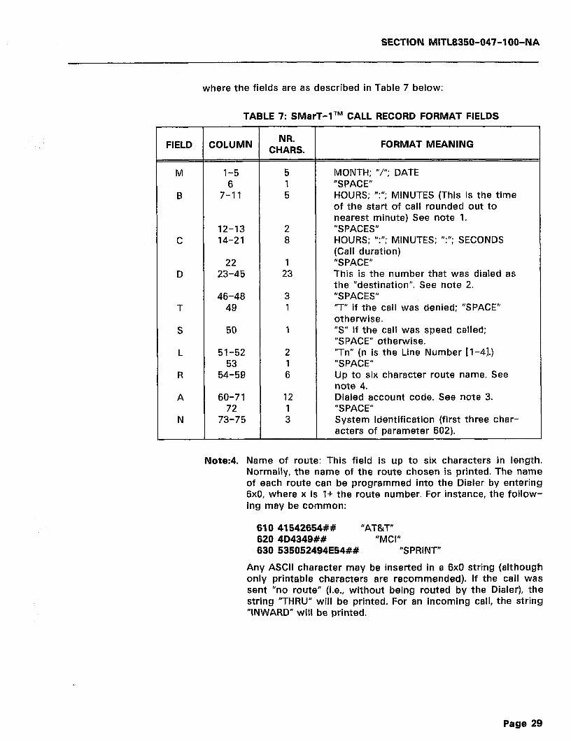
SECTION MITL8350-047-IOO-NA
where the fields are as described in Table 7 below:
TABLE 7: SMarT-ITM CALL RECORD FORMAT FIELDS
FIELD COLUMN NR’ CHARS. FORMAT MEANING
M l-5 5 MONTH; “I’; DATE 6 1 “SPACE”
B 7-11 5 HOURS; “:“; MINUTES (This is the time of the start of call rounded out to nearest minute) See note 1.
12-13 2 “SPACES” C 14-21 8 HOURS: “:“; MINUTES; “:“; SECONDS
(Call duration) 22 1 “SPACE”
D 23-45 23 This is the number that was dialed as the “destination”. See note 2.
46-48 3 “SPACES” T 49 1 “T” if the call was denied; “SPACE”
otherwise. S 50 1 ‘9’ if the call was speed called;
“SPACE” otherwise. L 51-52 2 “Tn” (n is the Line Number [l-4].)
53 1 “SPACE” R 54-59 6 Up to six character route name. See
note 4. A 60-7 1 12 Dialed account code. See note 3.
72 1 “SPACE” N 73-75 3 System Identification (first three char-
acters of parameter 602).
Note:4. Name of route: This field is up to six characters in length. Normally, the name of the route chosen is printed. The name of each route can be programmed into the Diater by entering 6x0, where x is I+ the route number. For instance, the follow- ing may be common:
610 41542654## “AT&T” 620 4D4349## “MCI” 630 535052494E54## “SPRINT”
Any ASCll character may be inserted in a 6x0 string (although only printable characters are recommended). If the call was sent “no route” (i.e., without being routed by the Dialer), the string “THRU” will be printed. For an incoming call, the string “INWARD” will be printed.
Page 29
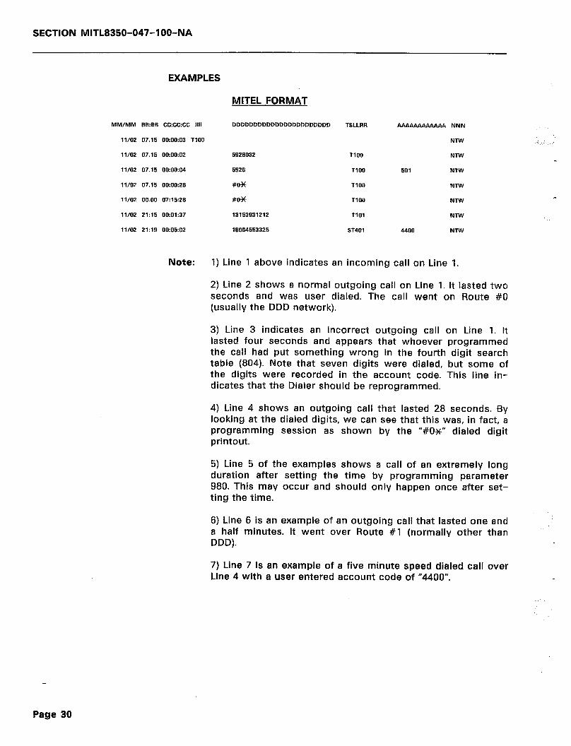
SECTION MITL8350-047-l OO-NA
EXAMPLES
MITEL FORMAT
MM/MM BB:BB Cc:CC:CC 1111
II/O2 07.15 00:00:03 TIOO
II/O2 07.15 00:00:02
11/02 07.15 00:OD:O4
11/02 07.15 0o:OO:ZB
IV02 00.00 07:15:28
11/02 21:15 00:01:37
11/02 21:19 00:05:02
5926032
5926
#H
#OX
13153931212
18064553325
TSLLRR - NNN
NTW
TlOO NTW
TlOO 501 NTW
TIOO NTW
TlOO NM
TlOl NTW
ST401 4400 NW
Note: 1) Line 1 above indicates an incoming call on Line 1.
2) Line 2 shows a normal outgoing call on Line 1. It lasted two seconds and was user dialed. The call went on Route #O (usually the DDD network).
3) Line 3 indicates an incorrect outgoing call on Line 1. It lasted four seconds and appears that whoever programmed the call had put something wrong in the fourth digit search table (804). Note that seven digits were dialed, but some of the digits were recorded in the account code. This line in- dicates that the Dialer should be reprogrammed.
4) Line 4 shows an outgoing call that lasted 28 seconds. By looking at the dialed digits, we can see that this was, in fact, a programming session as shown by the “#OX” dialed digit printout.
5) Line 5 of the examples shows a call of an extremely long duration after setting the time by programming parameter 980. This may occur and should only happen once after set- ting the time.
6) Line 6 is an example of an outgoing call that lasted one and a half minutes. It went over Route #I (normally other than DDD).
7) Line 7 is an example of a five minute speed dialed call over Line 4 with a user entered account code of “4400”.
Page 30
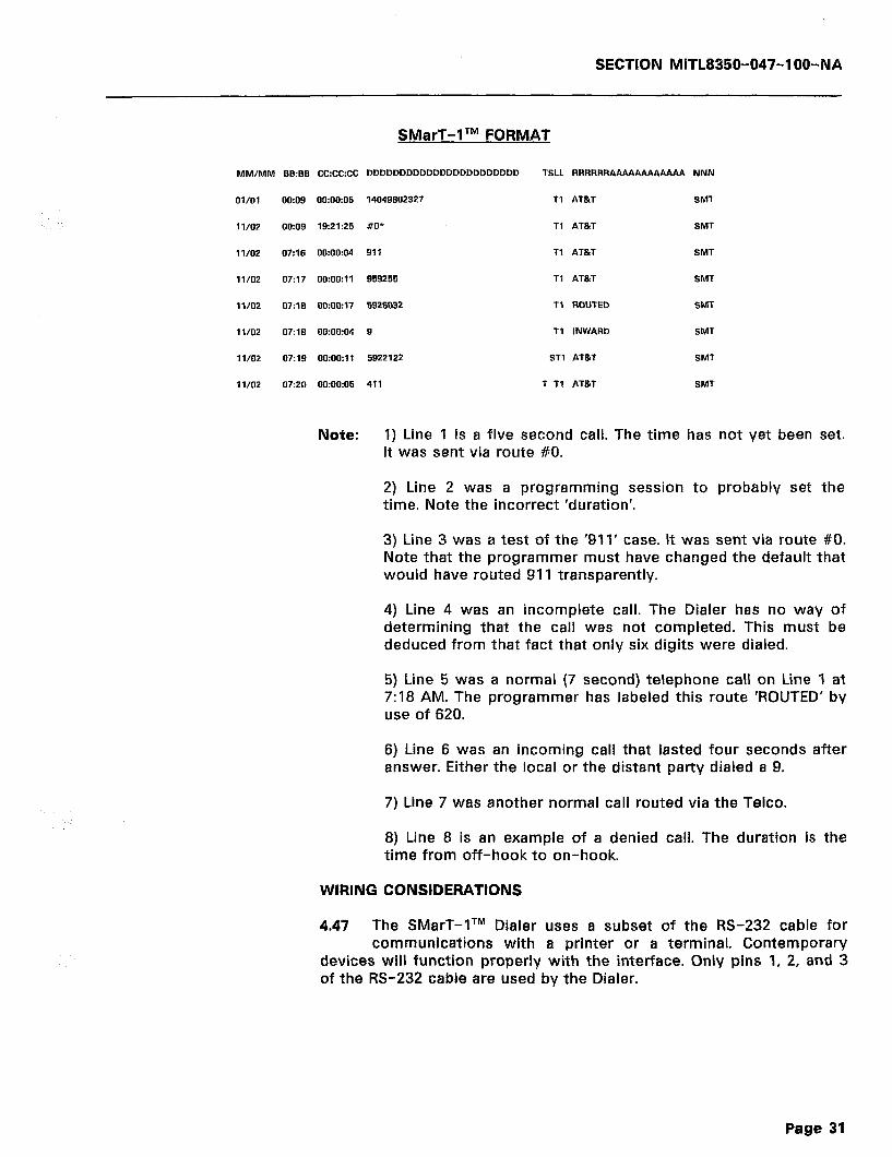
SECTION MlTL8350-047-l OO-NA
SMarT-1 TM FORMAT
MM/MM BB:BB CC:Cc:CC DDDDDDDDDDDDDDDDDDDDDDD TSLL RRRRRR NNN
Ol/Ol 00:09 00:00:05 14049602327 Tl AT&T SMT
1 l/O2 OR09 19:21:25 #O* Tl AT&T SMT
1 l/O2 07:16 00:00:04 911 Tl AT&T SMT
11/02 07:17 00:00:11 959255 Tl AT&T SMT
lVO2 D7:18 00:00:17 5926032 Tl ROUTED SMT
1 l/O2 07:lE 00:00:04 9 Tl INWARD SMT
1 l/O2 07:19 0D:OO:ll 5922122 ST1 AT&T SMT
1 l/O2 07:20 00:00:05 411 T Tl AT&T SMT
Note: 1) Line 1 is a five second call. The time has not yet been set. It was sent via route #O.
2) Line 2 was a programming session to probably set the time. Note the incorrect ‘duration’.
3) Line 3 was a test of the ‘911’ case. It was sent via route #O. Note that the programmer must have changed the default that would have routed 911 transparently.
4) Line 4 was an incomplete call. The Dialer has no way of determining that the call was not completed. This must be deduced from that fact that only six digits were dialed.
5) Line 5 was a normal (7 second) telephone call on Line ‘l at 7:18 AM. The programmer has labeled this route ‘ROUTED’ by use of 620.
6) Line 6 was an incoming call that lasted four seconds after answer. Either the local or the distant party dialed a 9.
7) Line 7 was another normal call routed via the Telco.
8) Line 8 is an example of a denied call. The duration is the time from off-hook to on-hook.
WIRING CONSIDERATIONS
4.47 The SMarT-lTM Dialer uses a subset of the RS-232 cable for communications with a printer or a terminal. Contemporary
devices will function properly with the interface. Only pins 1, 2, and 3 of the RS-232 cable are used by the Dialer.
Page 31
SECTION MITL8350-047-l OO-NA
4.48 Pin 1 is the ground for the Dialer. The wire is connected to pin 7 of the connector and to the grounding bolt. If any of the lines
are Ground Start, there may be moderate (0.5A) ground currents. To prevent this current from entering the user’s terminal or printer, ensure that the ground bolt is connected to a good earth ground.
4.49 Pin 2 is the data input to the Dialer. Any voltage from +0.5 to +3OV is considered as high while any voltage from -0.5 to -30V
is considered as a low.
4.50 Pin 3 is the data output from the Dialer. The transmitted high level is from +3 to +8V while the low is from -12 to -14V into
an open circuit. There may be up to 1 Volt of 60 Hz noise superim- posed on the logic level. The output impedance of this line is 1.5K& &5%.
4.51 Pin 4 is connected to Pin 5. This causes the RTS to be echoed back to the CTS (request to send echoed to clear to send).
4.52 Pin 6 is connected to pin 8 and, in turn, to pin 20. This echoes the DTR (data terminal ready) back to the CD (carrier detect)
and the DSR (data set ready).
4.53 These lines will allow direct connection of the Dialer to a terminal using a one to one cable. If the desired printer can also
connect directly to the terminal, it can be connected to the Dialer by use of a “NULL MODEM” cable. This only involves pins 1, 2, and 3.
Page 32
SECTION MITL8350-047-IOO-NA
5. DETAILED PROGRAMMING
INTRODUCTION
5.01 There are four ways to enter data into the Dialer: These meth- ods are listed below.
PROGRAMMING METHOD 1
Terminal or Computer
5.02 The Dialer may be easily connected to a personal computer via the RS-232 port, and, with an appropriate program, be com-
pletely programmed by responding to a series of questions and prompts presented by the personal computer. If a personal computer and a program are unavailable, the Dialer may be connected to a ‘dumb‘ terminal’ via the RS-232 port, and, by entering data, be pro- grammed via this terminal. The default program access code for this method is <CR>.
PROGRAMMING METHOD 2
DTMF Telephone
5.03 The Dialer also has a manual entry mode. Programming is accomplished by keying DTMF sequences on a DTMF telephone.
The tones may be on either side of the trunk interface (i.e., remote or local programming). For example, Trunk #2 may be configured as Ground Start by dialing “2 0 0 3”. The default program access code for this method is #OX.
PROGRAMMING METHOD 3
Tandem Mode
5.04 The Dialer may be remotely programmed by using a personal computer or a dumb terminal, and a second Dialer, both re-
motely located. The remote Dialer will dial up and access the Dialer to be programmed. To the user, this method appears identical to pro- gramming Method 1 with the exception that the default program ac- cess code is #OX.
PROGRAMMING METHOD 4
Cloning
5.05 Several Dialers can be programmed to operate identically. This can be accomplished by “cloning”. One Dialer is programmed by
any of the methods above. The other Dialers are “cloned” by connect- ing their computer ports together. The data exchange takes less than five seconds, and is initiated by dialing an access code from a set plugged into the Dialer unit whose program is to be copied.
Page 33
SECTION MITL8350-047-l OO-NA
5.06 Several other techniques may be used and are derivatives of the above. For instance, a cloned unit may have a few param-
eters changed via method 2. The time saved, compared to complete programming, is substantial.
5.07 An additional feature is an “auto-answer” mode which, if en- abled, allows remote programming of an unattended Dialer
while maintaining the security of unauthorized access via a series of parameters. There is also a separate limited access code for subscriber entry of speed calls.
DETAILED PROGRAMMING INSTRUCTIONS
1-:-::- .‘;::#j~tigi&uii i ,j Consideration should be given to the programming of 411
and 911 numbers. This is mentioned because of concern that the possibility of having the 411 or 911 codes pro- grammed to be non-functional. In some geographic loca- tions, this consideration extends to ‘0’. Test the Dialer thoroughly for the correct operation of these numbers after installation and programming.
METHOD 1
5.08 The Dialer, in all cases, is simple to program. The programming consists basically of two steps. Step one is to put the Dialer
into the programming mode. Step two is to enter the programming information by using one of the four methods previously mentioned.
5.09 If Method 1 is the selected data entry method, the computer, attached to the Dialer via the Computer (RS-232) port, will
present the user with screens of information. These screens may be easily modified by following the instructions also included on the screen. The computer will automatically communicate with the SMarT- lTM Dialer by using ASCII characters.
ASCII Compatible Terminal
5.10 A second procedure under programming method 1 allows the user to program the SMarT-1 Dialer by using an ASCII compati-
ble ‘dumb’ terminal. It requires no program to provide screens of information, but has the advantage of visual feedback for the program- mer, as well as, access to the “data confirmation” mode. The reference to ‘dumb’ terminal means that there are no programs resident to make it ‘smart’ such as a personal computer.
5.11 This method requires an ASCII terminal such as a DEC I/T-50? .s
or DEC !/T-100? (or compatible unit). If the terminal has an RS-232 port output and can be connected to the Dialer via an RS-232 (NULL MODEM) cable, in most cases, the terminal will support this procedure.
t VT-LOM-100 are Trademarks of Digital Equipment Corporation
Page 34
SECTION MITL8350-047-l OO-NA
5.12 The Dialer will accept input from the terminal as follows:
1) Characters are 0 through 9 and A through F. 2) Characters a through f are converted to characters A through F. 3) Characters X, x, 999, and <ESC> are used to exit the program
mode. 4) Characters ++ and a are the same as character A. 5) Characters #, B, <LF>, <CR>, <SPACE>, <PERIOD>, <COMMA>
and <HYPHEN> are all considered to be the character #. 6) ALL OTHER CHARACTERS ARE IGNORED.
5.13 The Terminal and the Dialer must be set to the same Baud rate (the default rate for the Dialer is 1200) with no parity, eight bits
per character with one stop bit and bit 8 sense set to space. The terminal must operate on-line in full duplex mode. The Dialer must already have been * initialized at least once.
5.14 Once the Dialer has been powered up, enter the security code. The terminal security code is defaulted to <CR> (carriage re-
turn). This will cause the Dialer to display a sign-on message similar to:
REV nn ENTERING PROG. MODE >
5.15 The field ‘nn’ in the example above is the Revision number of the software that is contained in the Dialer.
5.16 Once this display appears on the screen, the Dialer can be programmed. An example of a simple programming session is
included below. The left hand column shows the screen with the operator keyed information included in brackets [I. This is done so that the reader will not become confused with the Dialer responses. The right hand column includes any comments or notes for the particular line.
REV nn ENTERING PROG. MODE > [9021
> ES01 I 1#7*#7#90
> 19071 > [SO1 1#9##1
> [9021 > 1801 I #7#90 >[999lX or >[ESCI
Enter “data confirmation” mode (display memory mode). Display the contents of the 801 search table. Re-enter normal programming mode. Delete the first entry in 801 (#9 = de- lete). Enter data confirmation mode. Display contents of 801. Exit programming.
Page 35

SECTION MITL8350-047-l OO-NA
Note: Since this is operation with a dumb terminal, the contents of search tables will be displayed as one long string. It is up to the user to determine where the actual string entry ends or begins. This is accomplished by counting from the start of the Dialer display for the required number of characters particular to a search table.
5.17 If an invalid entry is made, the terminal will display a ‘? and proceed to the next line with a new prompt. If the Dialer is left
in the programming mode for more than a minute without making an entry on the terminal, a warning will be displayed saying that 60 seconds are left before exiting.
5.18 Further programming is accomplished by reading the applicable sections under programming Method 2 and applying this in-
formation by use of the Terminal keyboard.
METHOD 2
5.19 The following paragraphs deal with the programming of the Dialer from a telephone set. All of the character sequences
are identical to those used in the data exchange between the Dialer and the computer when using Method 1. These paragraphs will allow a user that is conversant with computer programming to fashion any kind of ‘up-load’, ‘down-load’, or interactive control pro- gram.
I::ij:i. ‘::i’&$&pY~ i; :
Consideration should be given to the programming of 411 and 911 numbers. This is mentioned because of concern that the possibility of having the 411 or 911 codes pro- grammed to be non-functional. In some geographic loca- tions, this consideration extends to ‘0’. Test the Dialer thoroughly for the correct operation of these numbers after installation and programming.
5.20 Before using the Dialer for the first time, a default base of data must be loaded into the unit by a special programming mode.
This is accomplished by the procedure outlined below:
1) Connect a DTMF telephone set to Line 1 of the unit.
2) Disconnect the power from the Dialer.
3) Using the telephone set, go off-hook. Push and Hold the x Key.
4) While holding the x Key, power the unit up.
5) Continue to hold the * Key for ten seconds or more.
6) Upon release of the s key, the unit will acknowledge with a short tone burst, audible in the earpiece. Default programming is now loaded and the Dialer is in the cut-through mode.
Page 36

SECTION MITL8350-047-l OO-NA
7) Place the DTMF telephone set on-hook.
5.21 The Dialer is now configured as:
0 All trunks loop start
a A single beep is used to notify the user that the Dialer is functioning
a There are no speed call numbers in the “700” speed call tables
0 The program security access code is #OX
Entering Programming Mode
First Time (New Dialer)
5.22 If this is the first time that the Dialer is to be programmed, a special method is required to put the Dialer into the program-
ming mode. This method is outlined by the steps listed under para- . graph 5.20 above.
5.23 After completing the steps outlined in paragraph 5.20, the first entry must be the security access code #OX so that the user
may continue with the programming steps under ‘Data Area’ below.
Other Than First Time
5.24 To enter the programming mode, enter the security access code that was used in paragraph 5.23 above or #OX if default
code is used. ’
ENTERING DATA
5.25 There are three distinct types of data that may be entered. These are PARAMETERS, STRINGS and SEARCH-TEMPLATES.
1) PARAMETERS consist of a four digit sequence where the first digit specifies the data area to be programmed, the next two digits specify the parameter to be programmed, and the fourth digit selects the specific information of interest such as number of seconds to wait, number of lines per page, etc.. In the case of the first digit of the four digit sequence, the meaning is:
0 = System Wide Data and Printer Related Data.
1 = Parameters relating to Trunk 1, Route #0, or Alternate Route # 0.
2 = Parameters relating to Trunk 2, Route #I, or Alternate Route # 1.
3 = Parameters relating to Trunk 3, Route #2, or Alternate Route # 2.
4 = Parameters relating to Trunk 4, Route #3, or Alternate Route # 3.
5 = Entry of data that is common to all four Trunks, Routes, or Al- ternate Routes. For example, ‘502t’ will program the DTMF Dialing Rate for all four trunks.
Page 37
SECTION MITL8350-047-l OO-NA
2) STRINGS consist of a three digit prefix with the first digit al- ways a ‘6’ or ‘7’, followed by an arbitrary number of digits (24 maximum), and ending with ‘##‘.
3) SEARCH TEMPLATES consist of a three digit prefix with the first digit always an ‘8’, followed by a sequence of digits. The three digit prefix selects the search table for data entry. The entry process is closed by entering a ‘##I.
‘::
Parameters
5.26 Table 8 below lists the four digit parameter codes for the Dialer. The letter ‘x’ or ‘r’ in the code represents a single user select-
able character for entry to select a specific specification of the param- eter. The letter ‘t’ represents a digit for entry.
.
5.27 After programming is completed, the unit should be checked to insure programming has accomplished the desired dialing char-
acteristics and activities. Ensure that the new program access code (if used)functions and then delete the default program access codes as follows:
GO OFF-HOOK
ENTER PROGRAM MODE using new access code
Delete the default accesses as follows:
803 #0 0 x #9
804 #9 #O 0 TX #9
HANG UP
5.28 If default program access codes are to be used, do not perform the above deletions.
Page 38
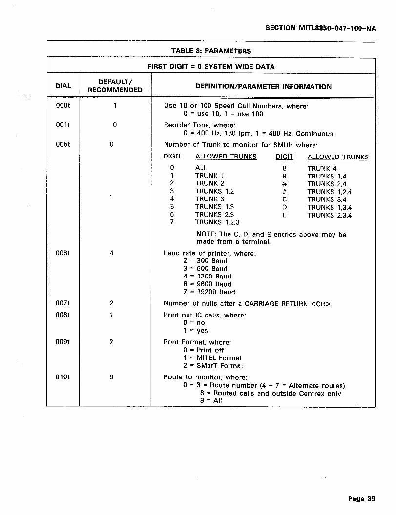
SECTION MITL8350-047-l OO-NA
TABLE 8: PARAMETERS
FIRST DIGIT = 0 SYSTEM WIDE DATA
DIAL DEFAULT/
RECOMMENDED DEFINITION/PARAMETER INFORMATION
ooot 1 Use 10 or 100 Speed Call Numbers, where: 0 = use 10, 1 = use 100
001t
005t
0
0
Reorder Tone, where: 0 = 400 Hz, 180 ipm, 1 = 400 Hz, Continuous
Number of Trunk to monitor for SMDR where:
DIGIT ALLOWED TRUNKS DIGIT ALLOWED TRUNKS
0 ALL 8 TRUNK 4 1 TRUNK 1 9 TRUNKS 1,4 2 TRUNK 2 TRUNKS 2,4 G% 3 TRUNKS 1,2 # TRUNKS 1,2,4 4 TRUNK 3 C TRUNKS 3,4 5 TRUNKS I,3 D TRUNKS 1,3,4 6 TRUNKS 2,3 E TRUNKS 2,3,4 7 TRUNKS 1,2,3
NOTE: The C, D, and E entries above may be made from a terminal.
006t 4 Baud rate of printer, where: 2 = 300 Baud 3 = 600 Baud 4 = 1200 Baud 6 = 9600 Baud 7 = 19200 Baud
007t
008t
009t
Number of nulls after a CARRIAGE RETURN <CR>.
Print out IC calls, where: 0 = no 1 = yes
Print Format, where: 0 = Print off 1 = MITEL Format 2 = SMarT Format
01ot 9 Route to monitor, where: 0 - 3 = Route number (4 - 7 = Alternate routes)
8 = Routed calls and outside Centrex only 9 = All
Page 39
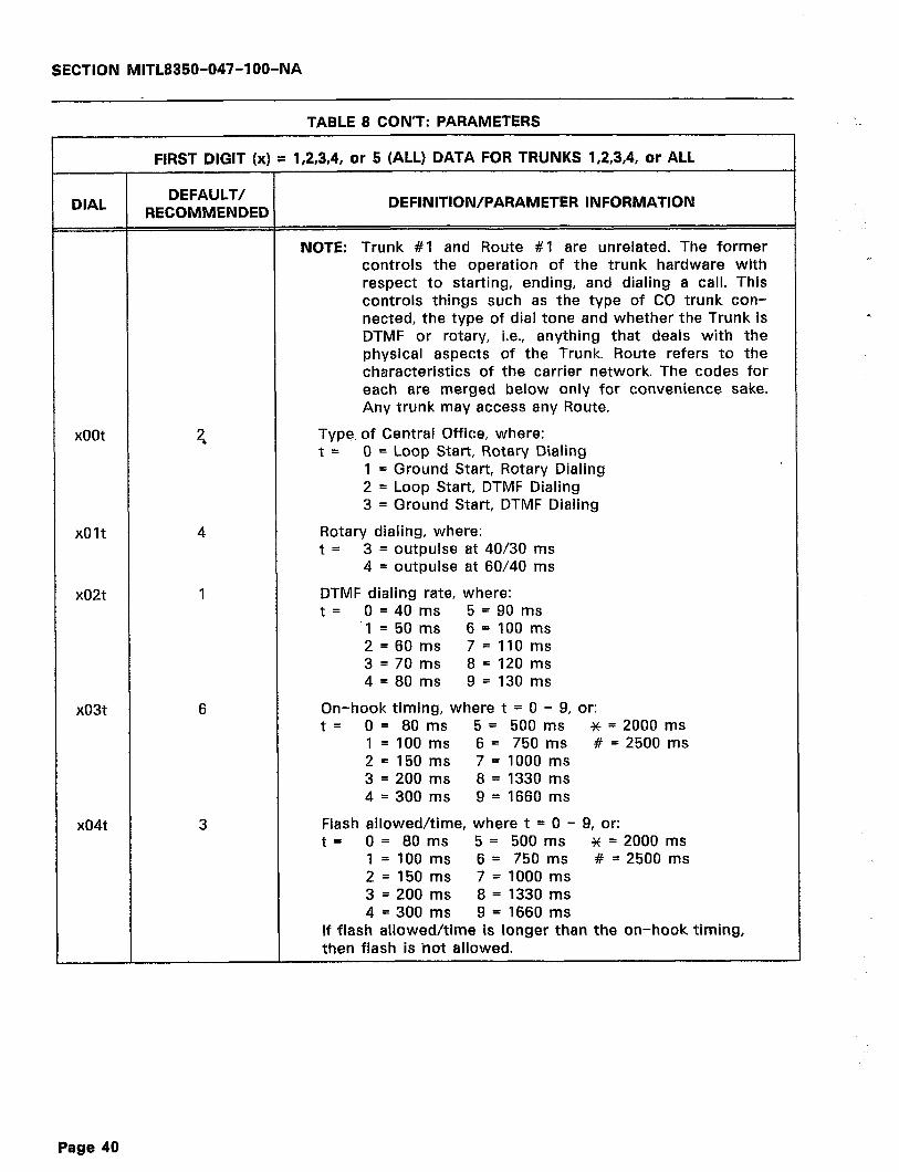
SECTION MITL8350-047-IOO-NA
TABLE 8 CON’T: PARAMETERS
FIRST DIGIT (x) = 1,2,3,4, or 5 (ALL) DATA FOR TRUNKS 1,2,3,4, or ALL
DIAL DEFAULT/
RECOMMENDED DEFINITION/PARAMETER INFORMATION
NOTE: Trunk #I and Route #I are unrelated. The former controls the operation of the trunk hardware with respect to starting, ending, and dialing a call. This controls things such as the type of CO trunk con- nected, the type of dial tone and whether the Trunk is DTMF or rotary, i.e., anything that deals with the physical aspects of the Trunk. Route refers to the characteristics of the carrier network. The codes for each are merged below only for convenience sake. Any trunk may access any Route.
xoot Type, of Central Office, where: t = 0 = Loop Start, Rotary Dialing
1 = Ground Start, Rotary Dialing 2 = Loop Start, DTMF Dialing 3 = Ground Start, DTMF Dialing
xOlt Rotary dialing, where: t 5 3 = outpulse at 40/30 ms
4 = outpulse at 60/40 ms
x02t
x03t
x04t 3
DTMF dialing rate, where: t I 0 = 40 ms 5 = 90 ms
‘1 = 50 ms 6 = 100 ms 2=60ms 7=llOms 3 = 70 ms 8 = 120 ms 4 = 80 ms 9 = 130 ms
On-hook timing, where t = 0 - 9, or: t I 0 = 80 ms 5 = 500 ms * = 2000 ms
l=lOOms 6= 750ms # = 2500 ms 2= 150 ms 7 = 1000 ms 3 = 200 ms 8 = 1330 ms 4 = 300 ms 9 = 1660 ms
Flash allowed/time, where t = 0 - 9, or: t = 0 = 80 ms 5 = 500 ms * = 2000 ms
l=lOOms 6= 750ms # = 2500 ms 2 = 150 ms 7 = 1000 ms 3 = 200 ms 8 = 1330 ms 4 = 300 ms 9 = 1660 ms
If flash allowed/time is longer than the on-hook timing, then flash is hot allowed.
Page 40

SECTION MlTLB350-047-l OO-NA
TABLE 8 CON’T: PARAMETERS
FIRST DIGIT (x) = 1,2,3,4, or 5 (ALL) DATA FOR TRUNKS 1,2,3,4, or ALL
DIAL DEFAULT/ RECOMMENDED DEFINITION/PARAMETER INFORMATION
x05t 0 Time between release and reseizure, where t = 0 - 9, or: t = 0= 500ms 5=1250ms
1 = 650 ms 6 = 1400 ms 2= 800ms 7=1550ms 3 = 950 ms 8 = 1700 ms 4 = 1100 ms 9 = 1850 ms
x06t 3 t = Number of ground start tries (failure goes to reorder tone).
x07t 3
x08t 3
t = Ground start timeout in seconds (Wait for TIP GND).
Off-hook digit refusal time, where t = 1 - 9, or: t= 0 = None 5 = .5 Sec.
1 = .I Sec. 6 = .6 Sec. 2 = .2 Sec. 7 = .7 Sec. 3= .3 Sec. 8 = .8 Sec. 4 = .4 Sec. 9 = .9 Sec.
x09t 4 User dial tone, where:
Silent Dialout Ticking Dialout t = 0 = None 2 = None
1 = Internal * 3 = internal * 4 = From C.O. 6 = From C.O.
* - Interacts with x19 Beep Options.
xlOt
xl 1t 3
Reserved for future use.
t = Inter-digit timeout on subscriber side, where t = 1 - 9, x and #, or: t = 0 = No timeout 6 = 12 seconds
1 = 2 seconds 7 = 14 seconds 2 = 4 seconds 8 = 16 seconds 3= 6 seconds 9 = 18 seconds 4= 8 seconds x = 20 seconds 5 = 10 seconds # = 22 seconds
x12t 2 t = Inter-digit timeout on 0+ calls. Same as xl It above.
x13t 2 t = Inter-digit timeout on Ol+ calls. Same as xllt above.
Page 41
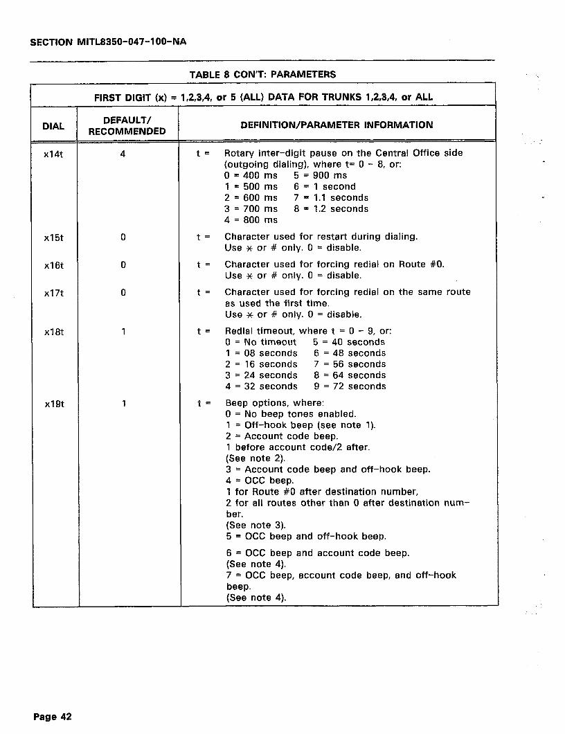
SECTION MlTL8350-047-l OO-NA
TABLE 8 CON’T: PARAMETERS
xI8t I
xI9t I
FIRST DIGIT (x) = l&3,4, or 5 (ALL) DATA FOR TRUNKS 1,2,3,4, or ALL
DIAL DEFAULT/
RECOMMENDED DEFINITION/PARAMETER INFORMATION
x14t t = Rotary inter-digit pause on the Central Office side (outgoing dialing), where t= 0 - 8, or: 0 = 400 ms 5 = 900 ms I = 500 ms 6 = 1 second 2 = 600 ms 7 = 1.1 seconds 3 = 700 ms 8 = I.2 seconds 4 = 800 ms
xI5t t= Character used for restart during dialing. Use * or # only. 0 = disable.
xI6t t= Character used for forcing redial on Route #O. Use * or # only. 0 = disable.
xI7t t= Character used for forcing redial on the same route as used the first time. Use x or # only. 0 = disable.
t = Redial timeout, where t = 0 - 9, or: 0 = No timeout 5 = 40 seconds 1 = 08 seconds 6 = 48 seconds 2 = I6 seconds 7 = 56 seconds 3 = 24 seconds 8 = 64 seconds 4 = 32 seconds 9 = 72 seconds
t = Beep options, where: 0 = No beep tones enabled. I = Off-hook beep (see note I). 2 = Account code beep. 1 before account code/2 after. (See note 2). 3 = Account code beep and off-hook beep. 4 = OCC beep. 1 for Route #O after destination number, 2 for all routes other than 0 after destination num- ber. (See note 3). 5 = OCC beep and off-hook beep.
6 = OCC beep and account code beep. (See note 4). 7 = OCC beep, account code beep, and off-hook beep. (See note 4).
Page 42

SECTION MITL8350-047-l OO-NA
TABLE 8 CON’T: PARAMETERS
-
.‘. . .
FIRST DIGIT (x) = 1,2,3,4, or 5 (ALL) DATA FOR TRUNKS 1,2,3,4, or ALL
DIAL DEFAULT/ RECOMMENDED
DEFINITION/PARAMETER INFORMATION
NOTE 1: If the off-hook beep options is chosen by itself (i.e., x191) or in conjunction with the other beep options, a beep will be heard when the telephone handset is lifted off the cradle, regardless of whatever route the call is dialed on.
NOTE 2: If the account code beep option is chosen (i.e., x192) the SMarT-lTM Dialer will insert a beep at the end of the destination number (which is before the account code is to be dialed). After the account code is entered, the second account code beep is heard.
NOTE 3: If the OCC beep option is chosen (i.e., x194), the SMarT-lTM Dialer will insert one beep after the destination number if the call is dialed on Route #0 (DDD). If the call is dialed on any other route, the OCC beep option will insert two beeps after the destination number.
NOTE 4: If the OCC beep option and the account code beep option are employed (i.e., xl96 or x197) and the call is dialed on Route #O (DDD), one beep after the destina- tion number and one beep after the account code will be heard. If dialed on any other route, two beeps will be heard after the destination number and one beep after the account code.
NOTE: If parameter x54t has the t value set to 1 (i.e., no account code), then account code beeps are disabled re- gardless of the x19t options chosen.
xzot 2 t= Ringing sensitivity, where t = 0 - 9 (0 is the most sensitive, and decreasing to 9, the least sensitive).
x21t 6
x22t 0
t= Inter-ring timing, in seconds.
t = Use primary or alternate search tables. 0 = Primary, 1 = Alternate
x23t 9 t= Activation of Dialer (what is done immediately after off-hook), where: 0 = Immediately dial Default Route
(Hotline Operation) 8 = Wait for digits; use search tables 9 = Cut-through
(Pass all digits directly through Dialer). (No Call-processing).
Page 43
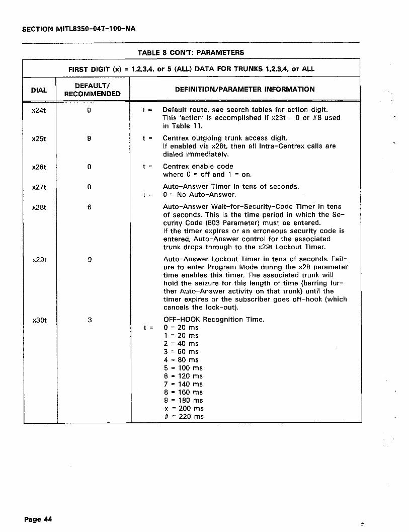
SECTION MITL835Q-047-IOO-NA
TABLE 8 CON’T: PARAMETERS
x26t 0
x27t 0
x28t 6
x29t 9
3
FIRST DIGIT (x) = 1,2,3,4, or 5 (ALL) DATA FOR TRUNKS 1,2,3,4, or ALL
DIAL DEFAULT/ RECOMMENDED
DEFINITION/PARAMETER INFORMATION
x24t 0 t = Default route, see search tables for action digit. This ‘action’ is accomplished if x23t = 0 or #8 used in Table 11.
x25t 9 t= Centrex outgoing trunk access digit. If enabled via x26t, then all Intra-Centrex calls are dialed immediately.
t= Centrex enable code where 0 = off and 1 = on.
Auto-Answer Timer in tens of seconds. t = 0 = No Auto-Answer.
Auto-Answer Wait-for-Security-Code Timer in tens of seconds. This is the time period in which the Se- curity Code (603 Parameter) must be entered. If the timer expires or an erroneous security code is entered, Auto-Answer control for the associated trunk drops through to the x29t Lockout Timer.
Auto-Answer Lockout Timer in tens of seconds. Fail- ure to enter Program Mode during the x28 parameter time enables this timer. The associated trunk will hold the seizure for this length of time (barring fur- ther Auto-Answer activity on that trunk) until the timer expires or the subscriber goes off-hook (which cancels the lock-out).
x30t OFF-HOOK Recognition Time. t= 0 = 20 ms
1 = 20 ms 2 = 40 ms 3 = 60 ms 4 = 80 ms 5 = 100 ms 6 = 120 ms 7 = 140 ms 8 = 160 ms 9 = 180 ms * = 200 ms # = 220 ms
9
Page 44 i
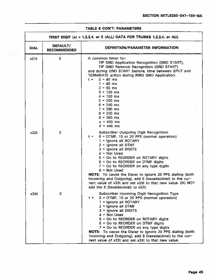
SECTION MITL8350-047-a 00-NA
TABLE 8 CON’T: PARAMETERS
FIRST DIGIT (x) = 1 2 3 4 or 5 (ALL) DATA FOR TRUNKS 1,2,3,4, or ALL , , , ,
DIAL DEFAULT/ RECOMMENDED
DEFINITION/PARAMETER INFORMATION
x31t 3 A common timer for: TIP GND Application Recognition (GND START), TIP GND Removal Recognition (GND START)
and during GND START Seizure, time between SPLIT and TERMINATE action during RING GND Application. t = 0 = 40 ms
1 = 40 ms 2 = 80 ms 3 = 120 ms 4= 160 ms 5 = 200 ms 6 = 240 ms 7 = 280 ms 8 = 320 ms 9 = 360 ms * = 400 ms # = 440 ms
x32t 0 Subscriber Outgoing Digit Recognition t= 0 = DTMF, 10 or 20 PPS (normal operation)
I = Ignore all ROTARY 2 = Ignore all DTMF 3 = Ignore all DIGITS 4 = Not Used 5 = Go to REORDER on ROTARY digits 6 = Go to REORDER on DTMF digits 7 = Go to REORDER on any type digits 8 = Not Used
NOTE: To cause the Dialer to ignore 20 PPS dialing (both Incoming and Outgoing), add 8 (hexadecimal) to the cur- rent value of x33t and set x33t to that new value. DO NOT add the 8 (hexadecimal) to x32t.
x33t 0 Subscriber Incoming Digit Recognition Type t = 0 = DTMF, IO or 20 PPS (normal operation)
1 = Ignore all ROTARY 2 = Ignore all DTMF 3 = Ignore all DIGITS 4 = Not Used 5 = Go to REORDER on ROTARY digits 6 = Go to REORDER on DTMF digits 7 = Go to REORDER on any type digits
NOTE: To cause the Dialer to ignore 20 PPS dialing (both Incoming and Outgoing), add 8 (hexadecimal) to the cur- rent value of x33t and set x33t to that new value.
Page 45

SECTION MlTL8358-047-IOO-NA
TABLE 8 CON’T: PARAMETERS
r55t *
r56t 3
7
FIRST DIGIT (r) = 1,2,3,4, or 5 (ALL) DATA FOR ROUTES 0 1 2 3 or ALL I I I r
DIAL DEFAULT/ RECOMMENDED DEFINITION/PARAMETER INFORMATION
r50t: 150t 250t 350t 450t
t= Destination number format where t = 0 - 9, or: 0 = Any number of digits (for Route #0) 1 = ten digits (adds user area code on seven digits) 2 = I+ ten digits (as above) 4 = I+ ten digits or I+ seven digits 8 = ten or seven digits
r5lt
r52t
r53t
r54t
Reserved for future use.
t = Account code number of digits, where t = 1 - 9
t= Account code wait timer in seconds (0 = No time- out). .
t= Account code type, where t = 0 - 5, or: 0 = Flexible length account code. Wait for timeout (previous entry) and then continue. 1 = No account code. x53t is not checked if x54t = 1. 2 = Fixed length. Wait for timeout. If not entered, then reorder tone. 3 = Fixed length. Wait for timeout. If not entered, then substitute the ‘dummy account code’. 4 = Same as 2 above, except that the number of digits in the account code is lO+ x52t above. 5 = Same as 3 above, except that the number of digits in the account code is IO+ x52t above.
t = Not On Network (NON) trigger character.
t = The length of time that a NON entry stays in the temporary search table (in tens of days).
r57t t = Number of digits stored in the search tables when NON is detected.
r58t: 158t 258t 358t 458t
t= Action as a result of call failure, where t = 0 - 9, * or: 0 = Redial on Route #0 1 = Redial on Route #I 2 = Redial on Route #2 3 = Redial on Route #3 4 = Reorder 5 = Redial same route once, then reorder 6 = Redial same route twice, then reorder 7 = Redial same route three times, then reorder 8 - Redial same route again, then Route 0 9 = Redial same route twice, then Route 0 K = Redial same route three times, then Route 0
Page 46
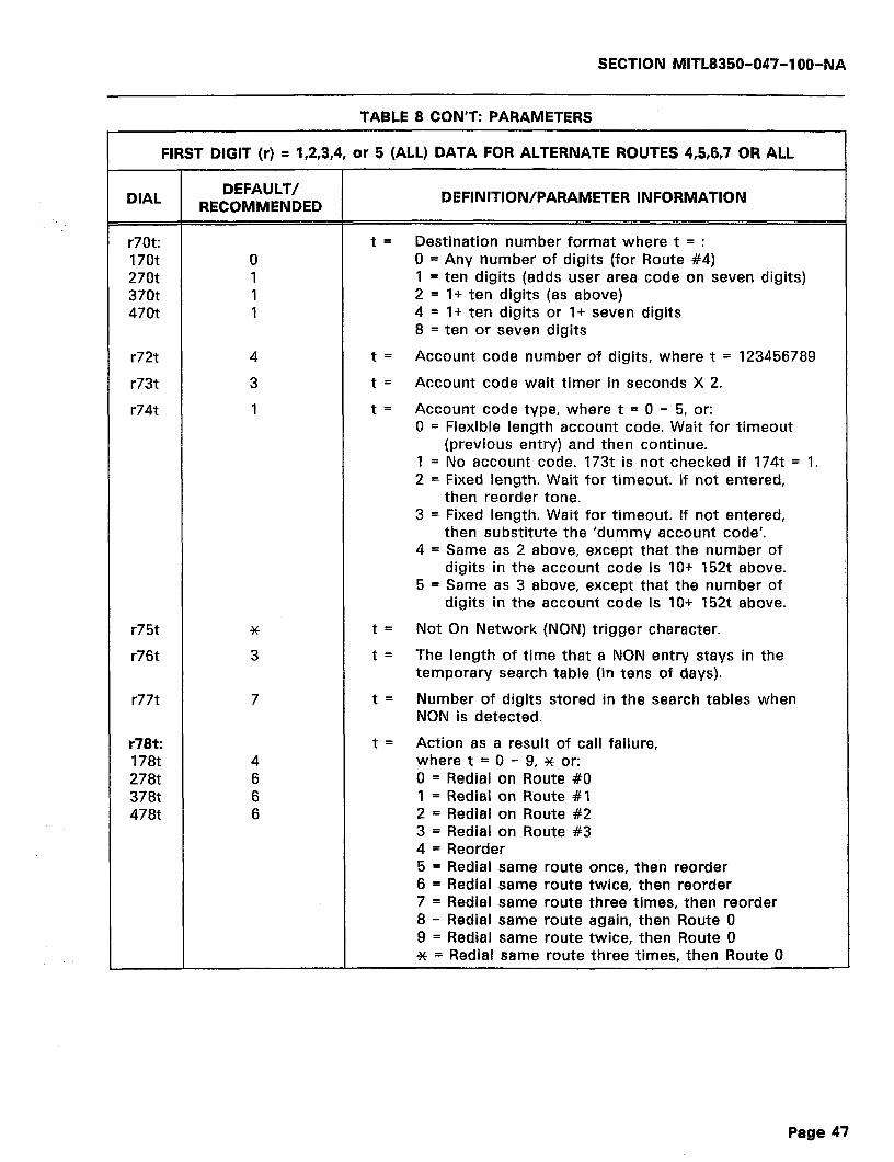
SECTION MITL8350-047-l OO-NA
TABLE 8 CON’T: PARAMETERS
FIRST DIGIT (r) = 1,2,3,4, or 5 (ALL) DATA FOR ALTERNATE ROUTES 4,5,6,7 OR ALL
DIAL DEFAULT/ RECOMMENDED
DEFINITION/PARAMETER INFORMATION
r70t: 170t 270t 370t 470t
t= Destination number format where t = : 0 = Any number of digits (for Route #4) 1 = ten digits (adds user area code on seven digits) 2 = l+ ten digits (as above) 4 = l+ ten digits or l+ seven digits 8 = ten or seven digits
r72t
r73t
r74t
t= Account code number of digits, where t = 123456789
t = Account code wait timer in seconds X 2.
t = Account code type, where t = 0 - 5, or: 0 = Flexible length account code. Wait for timeout
(previous entry) and then continue. 1 = No account code. 173t is not checked if 174t = 1. 2 = Fixed length. Wait for timeout. If not entered,
then reorder tone. 3 = Fixed length. Wait for timeout. If not entered,
then substitute the ‘dummy account code’. 4 = Same as 2 above, except that the number of
digits in the account code is lO+ 152t above. 5 = Same as 3 above, except that the number of
digits in the account code is lO+ 152t above.
r75t *
r76t 3
t = Not On Network (NON) trigger character.
t= The length of time that a NON entry stays in the temporary search table (in tens of days).
r77t 7 t= Number of digits stored in the search tables when NON is detected.
r78t: 178t 278t 378t 478t
4 6 6 6
t = Action as a result of call failure, where t = 0 - 9, * or: 0 = Redial on Route #0 1 = Redial on Route #l 2 = Redial on Route #2 3 = Redial on Route #3 4 = Reorder 5 = Redial same route once, then reorder 6 = Redial same route twice, then reorder 7 = Redial same route three times, then reorder 8 - Redial same route again, then Route 0 9 = Redial same route twice, then Route 0 * = Redial same route three times, then Route 0
Page 47

SECTION MITL8350-047-l OO-NA
Strings
5.29 Strings are entered as in Table 9 below. Where ‘number’ ap- pears after the initial three digits, a valid string of digits may be
entered. The string entry is terminated by the characters I##‘. If the ‘##’ is not entered, an ‘Automatic Entry’ Timer will automatically com- plete the parameter entry after expiration of the Inter-Digit Timer (xllt). Examples of string entries are included below.
EXAMPLE 1:
#80327
The string above is the default on Route #O (615). This string trans- lates to:
#803 Wait for minimum duration of precise dial tone for up to six seconds;
2 Dial destination number;
7 Cut-through.
EXAMPLE 2:
#8033#6~5427
The string above is the default on Route #I (625). It translates to:
#803 Wait for minimum duration of precise dial tone for up to six seconds.
3 Dial access number.
#625 Wait for 400 ms of 400 Hz tone from OCC for up to ten seconds.
4 Dial authorization code.
2 Dial destination number.
7 Cut-through.
5.30 These strings are entered as (refer to Table 8):
615 #80327## for Route 0 and 625 #8033#625427## for Route 1.
The 615 and 625 strings are constructed from the 6r5 Parameter in Table 9.
1.
Page 48

SECTION MITL8350-047-IOO-NA
TABLE 9: STRING DATA ENTRY
FIRST DIGIT = 6 STRINGS (where: r = 1 to 8 for Routes #0 to #7)
DIAL DEFINITION/STRING INFORMATION
6OOnumber## Reserved for future use.
6Olnumber## User area code (must be three digits, must always be entered).
602title## MACHINE IDENTIFIER (15 digits maximum and must be en- tered as ASCII codes).
603title## Auto-Answer Security Code (34 digits maximum). Default = #OS
604title##
6rOtitle##
Terminal Program Security Code (15 digits maximum). Default = <CR> (must be entered as ASCII Codes).
Name of Route (Six characters maximum). (Must be entered as ASCII codes).
6rl number## Access number (OCC phone number) (34 digits maximum).
6r2number##
6r3number##
Authorization number (34 digits maximum).
Dummy account number (34 digits maximum). (If this is empty, the dialer will wait for an account number to be dialed in until timeout occurs).
6rrlnumber## Centrex number. (Default = 9) (34 digits maximum, if desired).
6r5number##
615 and 655 Defaults: #80327
625, 635, 645, 665, 675 and 685 Defaults:
#8033#62~427
To program 601 and 6rO through 6r5 for DIAL-OUT of 4th column DTMF, see Table C2 ‘SPECIALS’ on Page C-5.
Access control sequence. This instructs the Dialer on how to access a particular network. All Route access control codes are sequences of digits as follows (and may be combined in any order):
1.0 Dial that digit. #Ox Dial a ‘K’. #OO Dial a ‘#I, #Ol Dial a ‘#’ if the last dial digit was not ‘#‘. #02 Wait for account code
(does not dial account code). #2ab Pause. Continue after pause if a = 5.
Fail to x58, x78 if a = 0 (see note 1). #3ab High tone (570-680 detector) (see note 1). #4ab 440 Hz detector (see note 1). #5ab 480 Hz/Ringback detector (see note 1). #6ab 400 Hz detector (see note 1). #7ab 350-620 Hz energy detector (see note 1). #8ab Precise dialtone/ Hz detector (see note 1). #gab Wait for Not On Network (NON) tone
(see note 1). #Dab DTMF Detector.
(Continued on next page)
.
Page 49
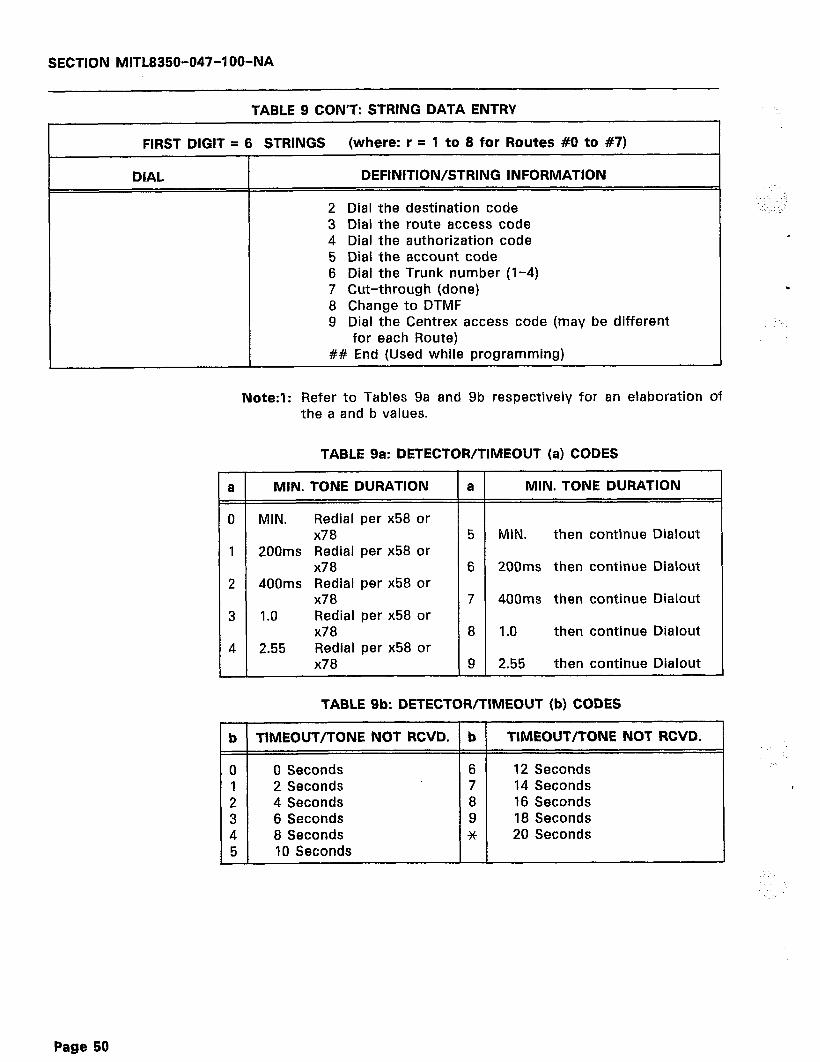
SECTION MITL8350-047-I OO-NA
TABLE 9 CON’T: STRING DATA ENTRY
FIRST DIGIT = 6 STRINGS (where: r = 1 to 8 for Routes #0 to #7)
DIAL DEFINITION/STRING INFORMATION
1
1
2 Dial the destination code 3 Dial the route access code 4 Dial the authorization code 5 Dial the account code 6 Dial the Trunk number (l-4) 7 Cut-through (done) 8 Change to DTMF 9 Dial the Centrex access code (may be different
for each Route) ## End (Used while programming)
Note:‘l: Refer to Tables 9a and 9b respectively for an elaboration of the a and b values.
TABLE 9a: DETECTOR/TIMEOUT (a) CODES
a MIN. TONE DURATION a MIN. TONE DURATION
0 MIN. Redial per x58 or x78 5 MIN. then continue Dialout
1 200ms Redial per x58 or x78 6 200ms then continue Dialout
2 400ms Redial per x58 or x78 7 400ms then continue Dialout
3 1.0 Redial per x58 or x78 8 1.0 then continue Dialout
4 2.55 Redial per x58 or x78 9 2.55 then continue Dialout
TABLE 9b: DETECTOR/TIMEOUT (b) CODES
b TlMEOUT/TONE NOT RCVD. b
0 0 Seconds 6 1 2 Seconds 7 2 4 Seconds 8 3 6 Seconds 9 4 8 Seconds * 5 10 Seconds
TIMEOUT/TONE NOT RCVD.
12 Seconds 14 Seconds 16 Seconds 18 Seconds 20 Seconds
Page 50
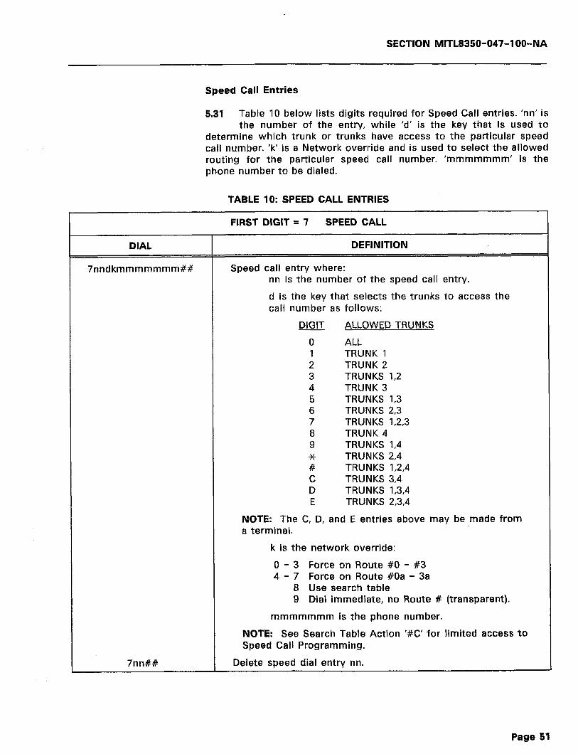
SECTION MlTL8350-047-l OO-NA
Speed Call Entries
5.31 Table 10 below lists digits required for Speed Call entries. ‘nn’ is the number of the entry, while ‘d’ is the key that is used to
determine which trunk or trunks have access to the particular speed call number. ‘k’ is a Network override and is used to select the allowed routing for the particular speed call number. ‘mmmmmmm’ is the phone number to be dialed.
TABLE 10: SPEED CALL ENTRIES
DIAL
7nndkmmmmmmm##
FIRST DIGIT = 7 SPEED CALL
DEFINITION
Speed call entry where: nn is the number of the speed call entry.
d is the key that selects the trunks to access the call number as follows:
DIGIT ALLOWED TRUNKS
0 ALL 1 TRUNK 1 2 TRUNK 2 3 TRUNKS 1,2 4 TRUNK 3 5 TRUNKS I,3 6 TRUNKS 2,3 7 TRUNKS 1,2,3 8 TRUNK 4 9 TRUNKS I,4 * TRUNKS 2,4 # TRUNKS 1,2,4 c TRUNKS 3,4 D TRUNKS 1,3,4 E TRUNKS 2,3,4
NOTE: The C, D, and E entries above may be made from a terminal.
k is the network override:
0 - 3 Force on Route #0 - #3 4 - 7 Force on Route #Oa - 3a
8 Use search table
7nn##
9 Dial immediate, no Route # (transparent).
mmmmmmm is the phone number.
NOTE: See Search Table Action ‘#C’ for limited access to Speed Call Programming.
Delete speed dial entry nn.
Page 51
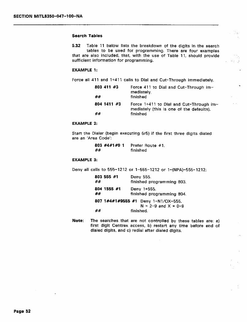
SECTION MITL8350-047-l OO-NA
Search Tables
5.32 Table 11 below lists the breakdown of the digits in the search tables to be used for programming. There are four examples
that are also included, that, with the use of Table 11, should provide sufficient information for programming.
EXAMPLE 1:
Force ail 411 and I+41 1 calls to Dial and Cut-Through immediately.
803 411 #3 Force 411 to Dial and Cut-Through im- mediately.
## finished
804 1411 #3 Force 1+411 to Dial and Cut-Through im- mediately (this is one of the defaults).
## finished
EXAMPLE 2:
Start the Dialer (begin executing 6r5) if the first three digits dialed are an ‘Area Code’:
803 #4#1#9 1 Prefer Route #l. ## finished
EXAMPLE 3:
Deny all calls to 555-1212 or 1-555-1212 or I-(NPA)-555-1212:
803 555 #l Deny 555. ## finished programming 803.
804 1555 #l Deny 1+555. ## finished programming 804.
807 1#4#1#9555 #l Deny I-Nl/OX-555. N = 2-9 and X = O-9
## finished.
Note: The searches that are not controlled by these tables are: a) first digit Centrex access, b) restart any time before end of dialed digits, and c) redial after dialed digits.
Page 52
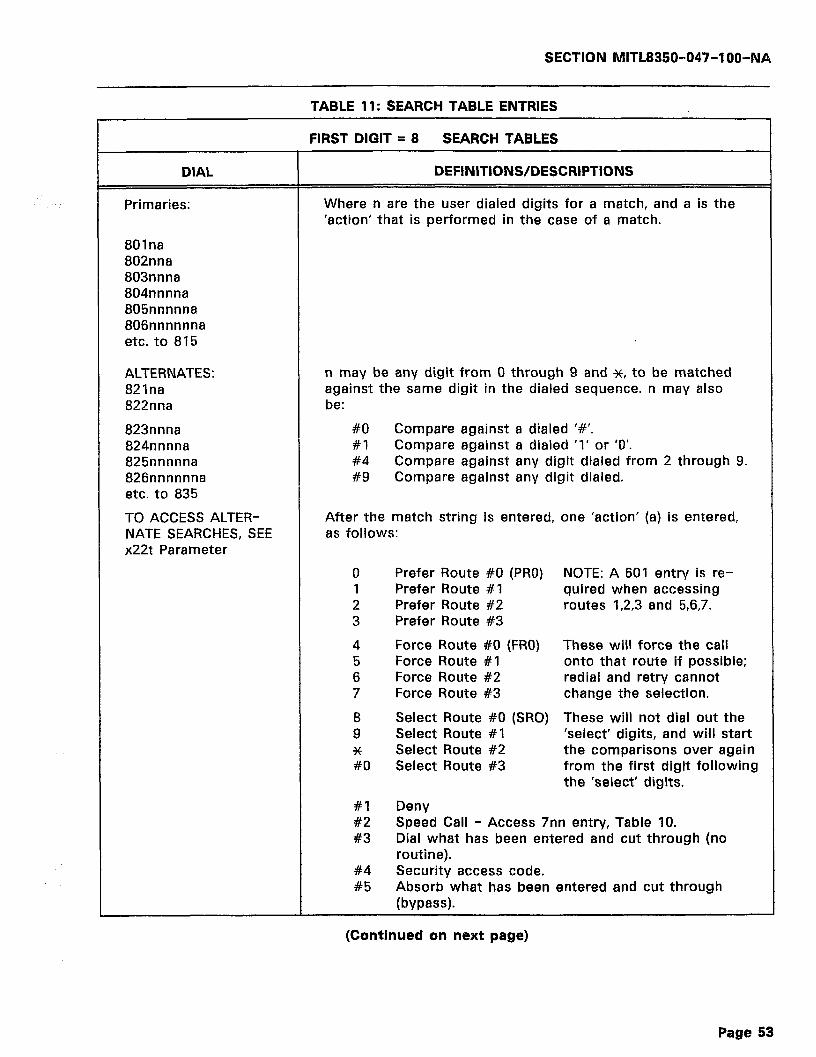
SECTION MITL8350-047-IOO-NA
TABLE 11: SEARCH TABLE ENTRIES
DIAL
Primaries:
FIRST DIGIT = 8 SEARCH TABLES
DEFINITIONS/DESCRIPTIONS
Where n are the user dialed digits for a match, and a is the ‘action’ that is performed in the case of a match.
801na 802nna 803nnna 804nnnna 805nnnnna 806nnnnnna etc. to 815
ALTERNATES: 821na 822nna
823nnna 824nnnna 825nnnnna 826nnnnnna etc. to 835
n may be any digit from 0 through 9 and *, to be matched against the same digit in the dialed sequence. n may also be:
#O Compare against a dialed I#‘. #I Compare against a dialed ‘1’ or ‘0’. #4 Compare against any digit dialed from 2 through 9. #9 Compare against any digit dialed.
TO ACCESS ALTER- NATE SEARCHES, SEE x22t Parameter
After the match string is entered, one ‘action’ (a) is entered, as follows:
0 Prefer Route #0 (PRO) NOTE: A 601 entry is re- 1 Prefer Route #I quired when accessing 2 Prefer Route #2 routes 1,2,3 and 5,6,7. 3 Prefer Route #3
4 Force Route #0 (FRO) These will force the call 5 Force Route #l onto that route if possible; 6 Force Route #2 redial and retry cannot 7 Force Route #3 change the selection.
a Select Route #0 (SRO) These will not dial out the 9 Select Route #I ‘select’ digits, and will start * Select Route #2 the comparisons over again #O Select Route #3 from the first digit following
the ‘select’ digits.
#I Deny #2 Speed Call - Access 7nn entry, Table 10. #3 Dial what has been entered and cut through (no
routine). #4 Security access code. #5 Absorb what has been entered and cut through
(bypass).
(Continued on next page)
Page 53
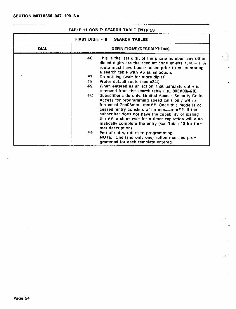
SECTION MITL8350-047-l OO-NA
TABLE 11 CON’T: SEARCH TABLE ENTRIES
FIRST DIGIT = 8 SEARCH TABLES
DIAL DEFINITIONS/DESCRIPTIONS
#6 This is the last digit of the phone number; any other dialed digits are the account code unless 154t = 1. A route must have been chosen prior to encountering a search table with #6 as an action.
#7 Do nothing (wait for more digits). #8 Prefer default route (see x24t). #9 When entered as an action, that template entry is
removed from the search table (i.e., 803#00++#9). #C Subscriber side only, Limited Access Security Code.
Access for programming speed calls only with a format of 7nn08mm....mm##. Once this mode is ac- cessed, entry consists of nn mm......mm##. If the subscriber does not have the capability of dialing the ##, a short wait for a timer expiration will auto- matically complete the entry (see Table 10 for for- mat description).
## End of entry, return to programming. NOTE: One (and only one) action must be pro- grammed for each template entered.
Page 54
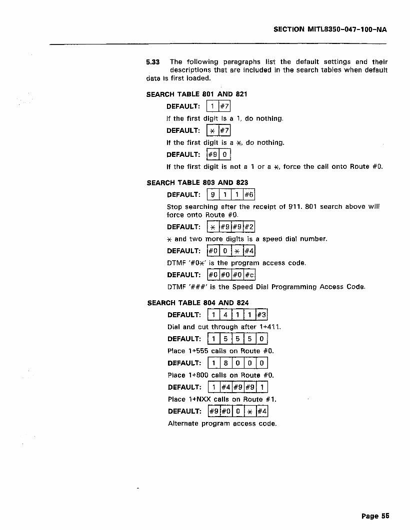
SECTION MITL8350-047-l OO-NA
5.33 The following paragraphs list the default settings and their descriptions that are included in the search tables when default
data is first loaded.
SEARCH TABLE 801 AND 821
DEFAULT: 111#71
If the first digit is a 1, do nothing.
DEFAULT: 1 x I#71
If the first digit is a x-, do nothing.
DEFAULT: I#9 1 0 1
If the first digit is not a 1 or a SC, force the call onto Route #O.
SEARCH TABLE 803 AND 823
DEFAULT: )g)/
Stop searching after the receipt of 911. 801 search above will force onto Route #O.
DEFAULT: 1 x I#9 I#9 I#21
* and two more digits is a speed dial number.
DEFAULT: 1#01oIx/#41
DTMF ‘#Ox’ is the program access code.
DEFAULT: [#o1#01#01#cl
DTMF ‘###’ is the Speed Dial Programming Access Code.
SEARCH TABLE 804 AND 824
DEFAULT: 111
Dial and cut through after 1+411.
DEFAULT: 11151515101
Place I+555 calls on Route #O.
DEFAULT: 1118101010]
Place 1+800 calls on Route #O.
DEFAULT: 11
Place l+NXX calls on Route #I.
DEFAULT: #9 #0 0 x #4
Alternate program access code.
Page 55

SECTION MITL8350-047-l OO-NA
SEARCH TABLE 807 AND 827
DEFAULT: 1 #4 #I #9 5 5 5 0
Place l+N(O or 1)X-555-xXxX calls on Route #O.
DEFAULT: #4 #4 #9 #9 #9 #9 #9 #6 T- Stop searching after receipt of NNX-XXXX (local call).
SEARCH TABLE 808 AND 828
DEFAULT: #1 #4 #4 #9 #9 #9 #9 #9 #6 Y Stop searching after receipt of l+NNX-XXXX (long distance call within the same area code).
SEARCH TABLE 810 AND 830
DEFAULT: #4 #I #9 #9 #9 #9 #9 #9 #9 #9 #6
Stop searching after receipt of N(0 or 1)X-XXX-XxXx (long dis- tance, outside of local area code).
SEARCH TABLE 811 AND 831
DEFAULT: #I #4 #I #9 #9 #9 #9 #9 #9 #9 #9 #6
Stop searching after receipt of a l+N(O or 1)X-XXX-XxXx (long distance, non-international call).
Note: To enable OCC dialing parameters, the 601 (area code), 621 (OCC access), and 622 (authorization code) values must be programmed.
Note: The search tables for the Alternate Routes are programmed by using numbers 821 through 835. These are used in the same manner as the numbers in the primary search tables. The ‘a’s used for 821 through 835 remain the same as the definitions for the ones used for 801 through 815. Alternate search tables can be accessed via x22t.
Special Functions
5.34 Table 12 (on the following page) contains the description of the programming entries required to invoke some special functions.
Modes 903, 904, 906 and 908 will affect calls in progress.
Page 56
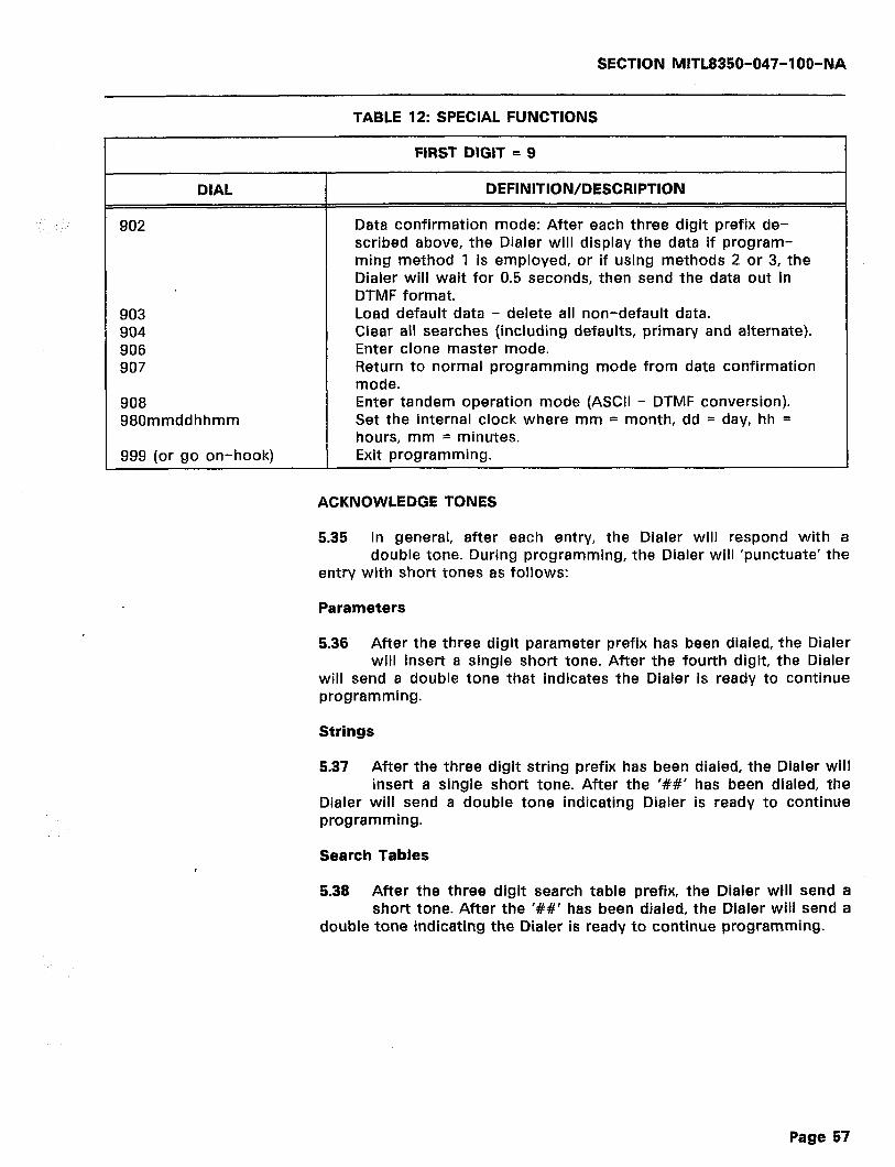
SECTION MlTL8350-047-I OO-NA
TABLE 12: SPECIAL FUNCTIONS
FIRST DIGIT = 9
DIAL DEFINITION/DESCRIPTION
902
903 904 906 907
908 980mmddhhmm
999 (or go on-hook)
Data confirmation mode: After each three digit prefix de- scribed above, the Dialer will display the data if program- ming method 1 is employed, or if using methods 2 or 3, the Dialer will wait for 0.5 seconds, then send the data out in DTMF format. Load default data - delete all non-default data. Clear all searches (including defaults, primary and alternate). Enter clone master mode. Return to normal programming mode from data confirmation mode. Enter tandem operation mode (ASCII - DTMF conversion). Set the internal clock where mm = month, dd = day, hh = hours, mm = minutes. Exit programming.
ACKNOWLEDGE TONES
5.35 In general, after each entry, the Dialer will respond with a double tone. During programming, the Dialer will ‘punctuate’ the
entry with short tones as follows:
Parameters
5.36 After the three digit parameter prefix has been dialed, the Dialer will insert a single short tone. After the fourth digit, the Dialer
will send a double tone that indicates the Dialer is ready to continue programming.
Strings
5.37 After the three digit string prefix has been dialed, the Dialer will insert a single short tone. After the ‘##’ has been dialed, the
Dialer will send a double tone indicating Dialer is ready to continue programming.
Search Tables
5.38 After the three digit search table prefix, the Dialer will send a short tone. After the ‘##’ has been dialed, the Dialer will send a
double tone indicating the Dialer is ready to continue programming.
Page 57
SECTION MITL8350-047-l OO-NA
Note: In the event of an illegal entry, the Dialer will send four long, slow beeps to indicate that the entry has been ignored. Wait for the tones to stop and then try again.
METHOD 3
Tandem Mode
5.39 Remote programming may be accomplished using a PC or dumb terminal in conjunction with a Dialer. The local Dialer will
perform as an ASCII to DTMF convertor in this mode and also has the advantage of visual feedback while programming a remote Dialer. This mode is also useful for data confirmation of a problem remote Dialer.
.
5.40 The network connection between the local and remote Dialer must be of reasonable quality with not more than a 20 dB loss.
5.41 To initiate TANDEM MODE, enter the PROGRAM MODE, then enter 502 9 (for a more reliable DTMF transmission) and then
enter the TANDEM MODE with the 908 command. The Dialer will be self-prompting on the screen. It will ask which line to use, will ac- knowledge receipt of the dial tone and will prompt for the phone number to dial. The user may pick up the associated phone at this point to converse with someone at the remote location. Once the remote Dialer has answered, enter the program access code. Upon receipt of the remote acknowledge tone, the remote phone will be split away and may be hung up.
5.42 The first command issued to the remote Dialer should be 502 9 (130 ms DTMF tones for more reliable data transmission) unless
it has been pre-set. At this point, standard terminal programming techniques may be used.
5.43 For data confirmation (902 mode), the TANDEM 7’ turn-around mode is most convenient. This places the local and remote
digits on separate lines on the screen which makes the data confirma- tion much easier to read. Use ‘X’ to return to regular mode from the turn-around mode.
5.44 The next to last command to the remote Dialer should be to return the x09t parameter to its original setting before pro-
gramming.
5.45 The ** LAST ** command to the remote Dialer should be 999 in order to exit the program mode in the remote Dialer. Failure to
do so will result in the remote Dialer trunk having to time-out of the program mode which essentially, results in that trunk being locked-up for the duration of the time-out.
Page 58
SECTION MITL8350-047-IOO-NA
METHOD 4
Cloning
5.46 “Cloning” is a programming method whereby several Dialers can be programmed to operate identically once one Dialer has
been set to the desired functions by another programming method. The Dialer that has the pr8-programmed instructions and is used to ‘clone’ another is called the ‘Master’. The unit to b8 programmed by this method is called the ‘Slave’.
5.47 This method must be accomplished by meeting the following conditions:
1. The Master unit cannot be processing any calls.
2. The Slave unit(s) must be fully operational and programmable from either a terminal or a DTMF handset.
3. Both the Master and the Slave units must b8 set for the same Baud rate.
4. This procedure will work correctly only if one Slave is con- nected to one Master at any one time during the cloning.
5. The Master unit must not be allowed to exit the program mode and no off-hook to on-hook transitions may occur in either unit while the RS-232 Cloning Cable is connected between the units.
Note: These transitions will cause an SMDR output that will confuse the units and possibly corrupt the programming of both units.
6.
5.48
1.
2.
3.
4.
5.
6.
The Slave unit must b8 powered down, then up after cloning and before attempting to use it. The Cloning Cable must be disconnected prior to powering the Slave unit up.
The following is a list of required equipment that is needed to accomplish this method of programming:
Pr8-programmed, dedicated Master unit.
DTMF handset or other DTMF source that will allow the Master unit to seize the line and generate tones.
A method of audibly detecting clone acknowledge tones on the Master Unit. A DTMF handset is allowable, or any other means of monitoring the audio on the subscriber side of the Master unit.
A battery or dummy CO source for the Master unit.
A power pack for each Dialer.
RS-232 Cloning Cable. The Dialer requires pins 1, 2, and 3 only. It is a NULL MODEM type with pins 2 and 3 reversed at one end.
Page 59
SECTION MITL8350-047-l OO-NA
Procedure
5.49
1.
2.
3.
4.
5.
6.
7.
8.
9.
IO.
11.
12.
5.50
The following steps are the procedure to be accomplished to clone a Dialer:
Ensure that the Dialers have been x initialized (see Page IO, para. 3.05).
Power up the Master unit.
Verify that the desired programming is already resident in the Master unit.
Power up the Slave unit.
Match the Master and Slave Baud rates.
Connect the Master and Slave RS-232 port connectors together with the Cloning Cable.
Go off-hook on the Master unit.
Dial the program access code (# 0 x unless it has been changed).
Dial ‘906’ to start the Clone procedure.
In approximately four to five seconds, one of two responses will occur. These are:
a) A double beep that indicates a successful clone has taken place and data has been transferred, or
b) Four long, slow beeps that indicate a failure of the clon- ing process. If this occurs, check the cable, the Baud rates, and the power connections, etc., to determine the cause of the failure.
After successful cloning, disconnect the Cloning Cable and power down the Slave unit.
DO NOT attempt to make the Slave unit function while the Cloning Cable is connected or prior to this power down.
Upon the next power up of the Slave unit, it will be functional and ready for operation with its data base being a copy of the
Master unit data base. If more units are to be cloned, repeat steps 2 through 11 for each unit.
Note: The ‘906’ Clone Command may be repeated at the Master unit any number of consecutive times until the desired number of units are cloned.
Page 60
SECTION MlTL8350-047-IOO-NA
Do not allow the Master to time out of the program mode or otherwise exit the program mode while the units are connected via the RS-232 Cloning Cable. The resulting SMDR output could cause data corruption of both units. The user may wish to turn the Master SMDR off (009 = 0) during the cloning and later restore it to its original set- ting if needed to minimize this error. A good rule to follow is to only have the Cloning Cable connected while actually cloning the unit.
Note: The cloning process occurs at a 19,200 Baud rate in order to proceed quickly (four to five seconds). The length of the Cloning Cable should be kept to a minimum and not coiled to allow uncorrupted transfer of data. The Master unit reverts to the programmed Baud rate upon completion of cloning and the Slave unit returns to its programmed Baud rate on the first power-up transition.
Page 61
SECTION MITL8350-047-IOO-NA
--- THIS PAGE INTENTIONALLY LEFT BLANK ---
Page 62

SECTION MITb6%60-Q47-l OO-NA
6. SPECIFICATIONS
HARDWARE
6.01 Table 13 lists all of the hardware specifications for the SMarT- lTM Common Carrier Access Dialer and Call Controller. These
specifications also apply to the SMarT-lATM unit unless otherwise noted.
TABLE 13: SMarT-lTM HARDWARE SPECIFICATIONS
SPECIFICATION MIN. TYP. MAX. UNITS
FCC RINGER EQUIVALENCE 0.78
IDLE LINE, LOOP START
RINGER IMPEDANCE: 15-60 Hz, 70-IIOV 10 20 K& 20-3500 Hz, 1OV 1 Mfi
RINGING SENSITIVITY: 15-60 Hz 40 Volts
LEAKAGE: Tip to Ring, 1OOV 20 MQ Tip to Earth, IOOV 20 M!J
OFF HOOK CURRENT 15 80 mA
IDLE LINE, GROUND START
SENSING RESISTANCE: Tip to Earth 36 40 .45 Kfi
OPEN CIRCUIT VOLTAGE: Tip -22 -25 . -28 Volts
GROUNDING VOLTAGE -5 0 +lO Volts
TIME TO RECOGNIZE TIP-GROUND 10 150 ms
RESISTANCE: Sending Ring-Ground n/a
BATTERY FEED
OPEN CIRCUIT VOLTAGE 22 24 26 Volts
FEED RESISTANCE 550 600 650 sz
BALANCE: DC 36 40 dB
SHORT CIRCUIT CURRENT 50 mA
TERMINATION
RESISTANCE: DC, 20 mA 200 300 D DC, 40 mA 200 300 sit
AC, 300-3000 Hz 550 600 650 i-l?
RETURN LOSS: 600 ohms, 20mA 20 26 dB
OPERATING CURRENT 13 80 mA
Page 63

SECTION MITL6360-047-l OO-NA
TABLE 13 CON’T: SMarT-lTM HARDWARE SPECIFICATIONS
SPECIFICATION MIN. TYP. MAX. UNITS
DIAL TONE
CO SIDE FEED:
INTERNAL FEED:
DTMF RECEIVER
LEVEL
LEVEL DIFFERENCE
FREQ:
DURATION
TIME BETWEEN TONES
ROTARY RECEIVER
MAKE IMPEDANCE
MAKE DURATION
BREAK IMPEDANCE
BREAK DURATION
RATE
DTMF SENDER
LEVEL
FREQUENCY
DURATION (Programmable)
ROTARY SENDER
TIMING (Programmable)
TIMING (At 60/40):
RATE (At 60/40)
Gain 300 Hz
350 Hz
To receive To not receive
Make Break
INTERDIGIT PAUSE (Programmable)
OPERATING RANGE
TEMPERATURE
HUMIDITY
ALLOWABLE VOLTAGE: connected to any point
-2
-20
-6
-1.5 -3.5
40
30
20
8
20
7
-8
-1.3
40
40/30
35 55
9.9
400
0
0
0
n/a
-6
60
60140
10
800
+2 dB
+3
+6
+I.5 +3.5
dBmt
dB
% %
ms
ms
700
100
100
20
fl
ms
Ka
ms
PPS
-3 dBmt
+I.3 %
130 ms
60/40 ms/ms
45 ms 65 ms
10.1 PPS
1300 ms
55
85
300
“C
%
Volts
T With reference to 6000 Termination.
Page 64
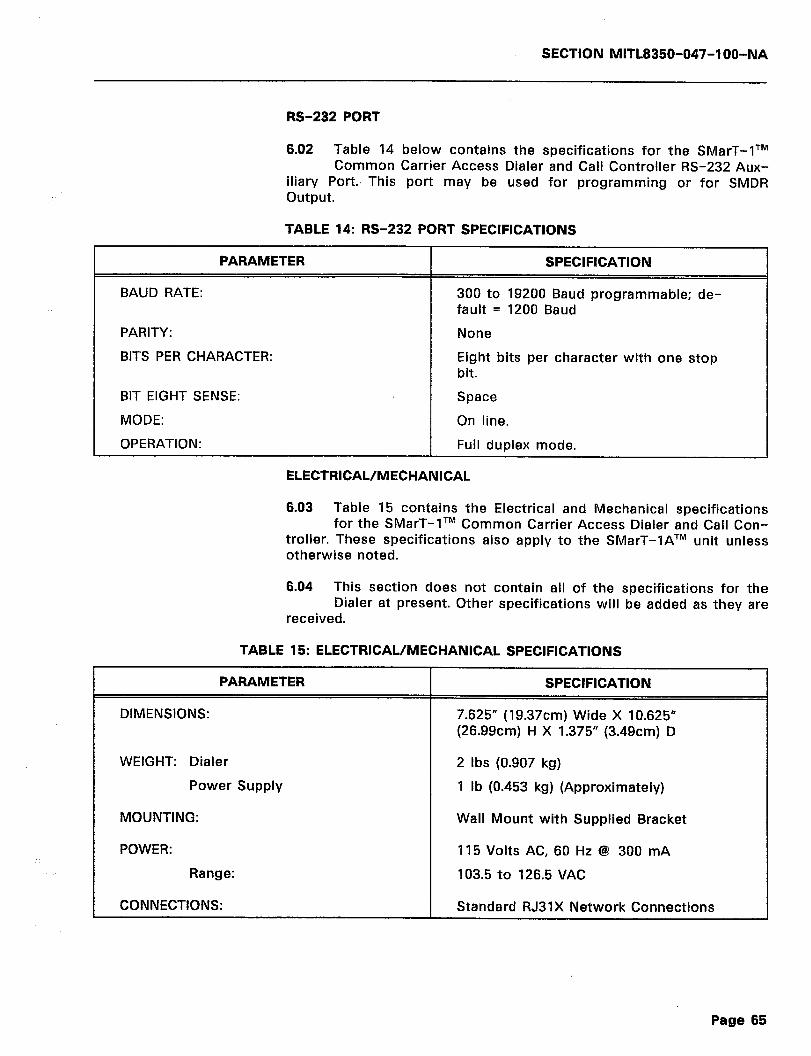
SECTION MITL8350-047-l OO-NA
RS-232 PORT
6.02 Table 14 below contains the specifications for the SMarT-lTM Common Carrier Access Dialer and Call Controller RS-232 Aux-
iliary Port., This port may be used for programming or for SMDR output.
TABLE 14: RS-232 PORT SPECIFICATIONS
PARAMETER
BAUD RATE:
PARITY:
BITS PER CHARACTER:
BIT EIGHT SENSE:
MODE:
OPERATION:
SPECIFICATION
300 to 19200 Baud programmable; de- fault = 1200 Baud
None
Eight bits per character with one stop bit.
Space
On line.
Full duplex mode.
ELECTRICAL/MECHANICAL
6.03 Table 15 contains the Electrical and Mechanical specifications for the SMarT-lTM Common Carrier Access Dialer and Call Con-
troller. These specifications also apply to the SMarT-lATM unit unless otherwise noted.
6.04 This section does not contain all of the specifications for the Dialer at present. Other specifications will be added as they are
received.
TABLE 15: ELECTRICAL/MECHANICAL SPECIFICATIONS
PARAMETER
DIMENSIONS:
WEIGHT: Dialer
Power Supply
MOUNTING:
POWER:
Range:
CONNECTIONS:
SPECIFICATION
7.625” (19.37cm) Wide X 10.625” (26.99cm) H X 1.375” (3.49cm) D
2 Ibs (0.907 kg)
1 lb (0.453 kg) (Approximately)
Wall Mount with Supplied Bracket
115 Volts AC, 60 Hz @ 300 mA
103.5 to 126.5 VAC
Standard RJ31X Network Connections
Page 65

SECTION MITL8350-047-l OO-NA
6.05 The specifications in the Tables above are subject to change without notice. The inclusion of ‘n/a’ for a specific parameter
means that the specification is not available at the time of this pub- lication. It will be added at a later date.
.I
Page 66
SECTION MITL8350-047-l OO-NA
7. MAINTENANCE
GENERAL
7.01 The Dialer, as is evident, is a fully self-contained unit. As such, it has no user repairable parts. If the warranty seal over the unit
fasteners is broken, the warranty is void. In case of failure, replace the Dialer as follows:
1) Power down the unit. This will cut-through the subscriber side to the CO side.
2) Remove the RJ31 plug from the Telco supplied socket. The shorting bars in the RJ31X will cut-through to the line. Then,
3) Replace the Dialer and re-connect.
4) Proceed as if a new installation.
Page 57
SECTION MITL8350-047-l OO-NA
--- THIS PAGE INTENTIONALLY LEFT BLANK ---
3
.
Page 58

SECTION MITL8350-047-l OO-NA
8. ORDERING INFORMATION
GENERAL
PART NO.
8350-00 1
8.01 Table 16 below lists the part numbers and descriptions of items that can be ordered from MITEL DATACOM INC.
TABLE 16: SMarT-lTM ORDERING INFORMATION
DESCRIPTION
SMarT-1: 4 Line Common Carrier Access Dialer and Call Controller. Includes Power Pack, RJ31 Cables, and Wall Mount Bracket.
8350-002 SMarT-1A: 2 Line Common Carrier Access Dialer and Call Controller. Includes Power Pack, RJ31 Cables, and Wall Mount Bracket. o
SPARES
8350-010 Wall Mount Bracket for SMarT-lTM and SMarT-lATM units.
8350-011 Power Pack for SMarT-lTM and SMarT-lATM units.
8350-012 Power Pack for SMarT-lTM and SMarT-lATM units.
8350-013 RJ31X Cable for SMarT-lTM and SMarT-lATM units.
8350-015 Cloning Cable
8350-953-00 1 -NA Installation and Abbreviated Programming Guide
8350-047-l 00-NA General Information Manual
Page 69
SECTION MITL8350-047-IOO-NA
--- THIS PAGE INTENTIONALLY LEFT BLANK ---
Page 70
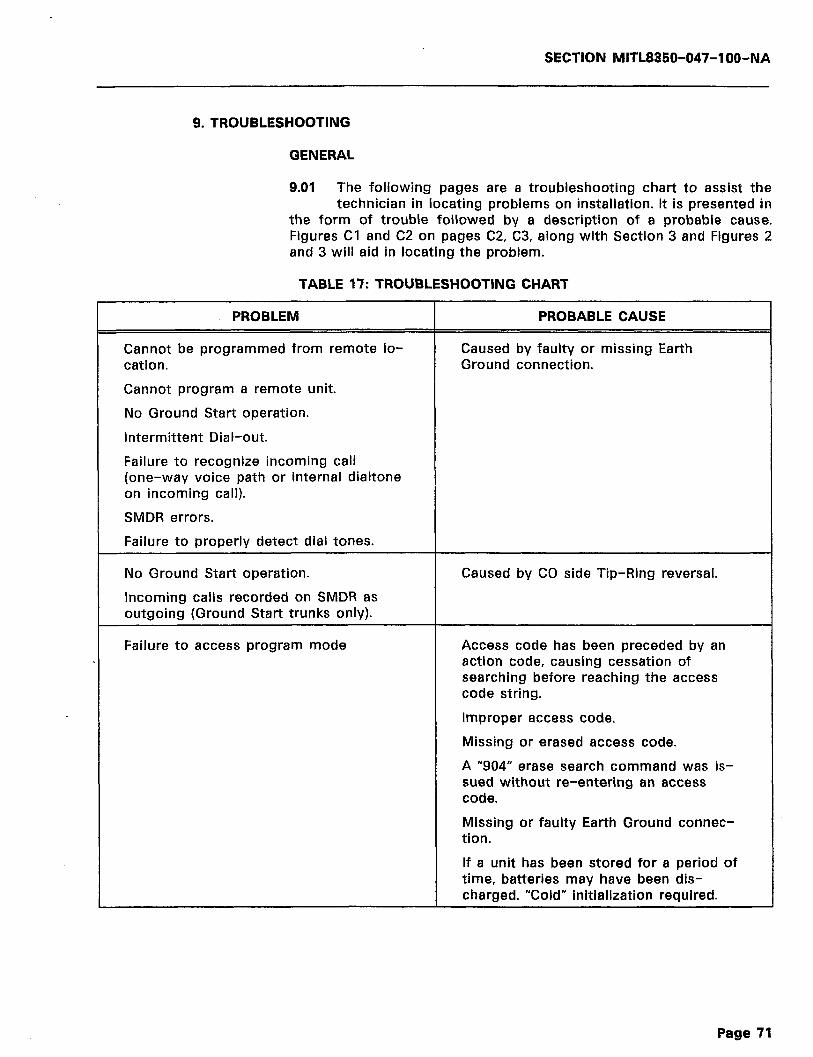
SECTION MlTL8850-047-l OO-NA
9. TROUBLESHOOTING
GENERAL
9.01 The following pages are a troubleshooting chart to assist the technician in locating problems on installation. It is presented in
the form of trouble followed by a description of a probable cause. Figures Cl and C2 on pages C2, C3, along with Section 3 and Figures 2 and 3 will aid in locating the problem.
TABLE 17: TROUBLESHOOTING CHART
PROBLEM
Cannot be programmed from remote lo- cation.
Cannot program a remote unit.
No Ground Start operation.
Intermittent Dial-out.
PROBABLE CAUSE
Caused by faulty or missing Earth Ground connection.
Failure to recognize incoming call (one-way voice path or internal dialtone on incoming call).
SMDR errors.
Failure to properly detect dial tones.
No Ground Start operation.
Incoming calls recorded on SMDR as outgoing (Ground Start trunks only).
Caused by CO side Tip-Ring reversal.
Failure to access program mode Access code has been preceded by an action code, causing cessation of searching before reaching the access code string.
Improper access code.
Missing or erased access code.
A “904” erase search command was is- sued without re-entering an access code.
Missing or faulty Earth Ground connec- tion.
If a unit has been stored for a period of time, batteries may have been dis- charged. “Cold” initialization required.
Page 71
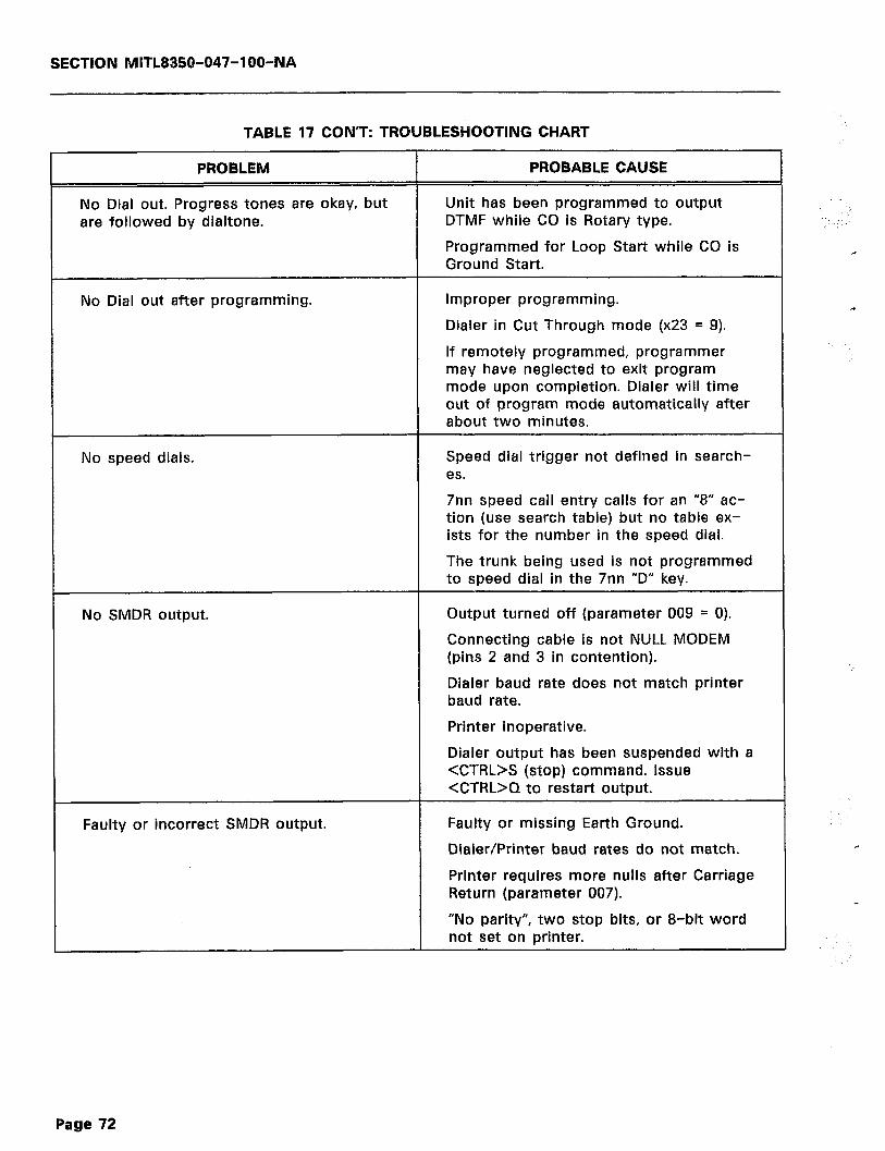
SECTION MITL8350-047-l OO-NA
TABLE 17 CON’T: TROUBLESHOOTING CHART
PROBLEM
No Dial out. Progress tones are okay, but are followed by dialtone.
PROBABLE CAUSE
Unit has been programmed to output DTMF while CO is Rotary type.
Programmed for Loop Start while CO is Ground Start.
No Dial out after programming. Improper programming.
Dialer in Cut Through mode (x23 = 9).
If remotely programmed, programmer may have neglected to exit program mode upon completion. Dialer will time out of program mode automatically after about two minutes.
No speed dials. Speed dial trigger not defined in search- es.
7nn speed call entry calls for an “8” ac- tion (use search table) but no table ex- ists for the number in the speed dial.
The trunk being used is not programmed to speed dial in the 7nn “D” key.
No SMDR output. Output turned off (parameter 009 = 0).
Connecting cable is not NULL MODEM (pins 2 and 3 in contention).
Dialer baud rate does not match printer baud rate.
Printer inoperative.
Dialer output has been suspended with a <CTRL>S (stop) command. Issue <CTRL>Q to restart output.
Faulty or incorrect SMDR output. Faulty or missing Earth Ground.
Dialer/Printer baud rates do not match.
Printer requires more nulls after Carriage Return (parameter 007).
“No parity”, two stop bits, or 8-bit word not set on printer.
Page 72

SECTION MITL8350-047-IOO-NA
TABLE 17 CON’T: TROUBLESHOOTING CHART
PROBLEM
Call waiting signal or flash-hook for hold .drops call.
PROBABLE CAUSE
On-hook timing too short (x03).
Flash allowed timing too short (x04).
Flash allowed timing set for a longer pe- riod that on-hook timing.
Failure to acquire dialtone on redial functions.
Dialer re-order tone during slow dialing.
No Centrex operation.
x05 time between release and reseize is too short for the particular CO.
xl 1 inter-digit timeout too short.
Not enabled (parameter x26 = 0).
x25 Centrex digit not programmed to desired digit.
Parameter 6R4 not programmed if oc- curring on auto dialing.
Improper OCC dialing. 601 area code not programmed (must be programmed to something even if not used in access control sequence).
6R5 access control sequence not pro- grammed for dial tones present, or wrong route programmed (615 = route 0, 625 = 1, etc.).
Access number not programmed for that route (6Rl).
No cut through (7) code in 6R5 param- eter.
No #6 code in 8xx search; results in de- lay before cut through.
Carefully check 800 searches and access control sequences.
Improper destination number format (x70).
911 Emergency number, or 411, etc., will not work.
One of the 800 searches has superseded it. Always be sure to check the function of emergency numbers.
911, 411, etc., not available on that ex- change.
Page 73
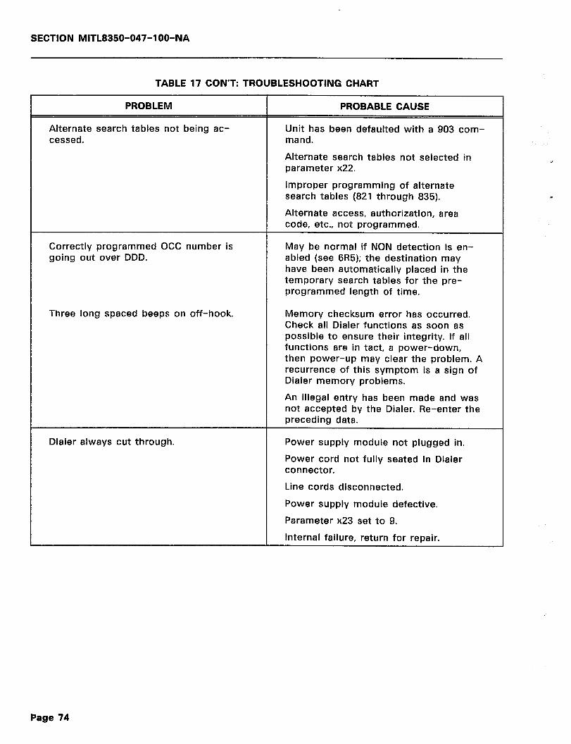
SECTION MITL835t.b047-l OO-NA
TABLE 17 CON’T: TROUBLESHOOTING CHART
PROBLEM
Alternate search tables not being ac- cessed.
PROBABLE CAUSE
Unit has been defaulted with a 903 com- mand.
Alternate search tables not selected in parameter x22.
Improper programming of alternate search tables (821 through 835).
Alternate access, authorization, area code, etc., not programmed.
Correctly programmed OCC number is going out over DDD.
May be normal if NON detection is en- abled (see 6R5); the destination may have been automatically placed in the temporary search tables for the pre- programmed length of time.
Three long spaced beeps on off-hook. Memory checksum error has occurred. Check all Dialer functions as soon as possible to ensure their integrity. If all functions are in tact, a power-down, then power-up may clear the problem. A recurrence of this symptom is a sign of Dialer memory problems.
An illegal entry has been made and was not accepted by the Dialer. Re-enter the preceding data.
Dialer always cut through. Power supply module not plugged in.
Power cord not fully seated in Dialer connector.
Line cords disconnected.
Power supply module defective.
Parameter x23 set to 9.
Internal failure, return for repair.
Page 74
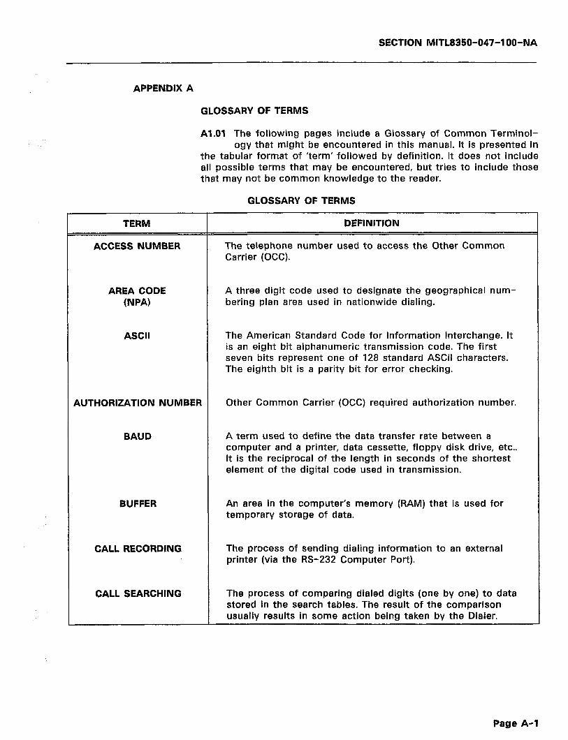
SECTION MITL8350-047-l OO-NA
APPENDIX A
GLOSSARY OF TERMS
Al.01 The following pages include a Glossary of Common Terminol- ogy that might be encountered in this manual. It is presented in
the tabular format of ‘term’ followed by definition. It does not include all possible terms that may be encountered, but tries to include those that may not be common knowledge to the reader.
GLOSSARY OF TERMS
TERM
ACCESS NUMBER
DEFINITION
The telephone number used to access the Other Common Carrier (OCC).
AREA CODE (NW
ASCII
A three digit code used to designate the geographical num- bering plan area used in nationwide dialing.
The American Standard Code for Information Interchange. It is an eight bit alphanumeric transmission code. The first seven bits represent one of 128 standard ASCII characters. The eighth bit is a parity bit for error checking.
AUTHORIZATION NUMBER
BAUD
Other Common Carrier (OCC) required authorization number.
A term used to define the data transfer rate between a computer and a printer, data cassette, floppy disk drive, etc.. It is the reciprocal of the length in seconds of the shortest element of the digital code used in transmission.
BUFFER An area in the computer’s memory (RAM) that is used for temporary storage of data.
CALL RECORDING The process of sending dialing information to an external printer (via the RS-232 Computer Port).
CALL SEARCHING The process of comparing dialed digits (one by one) to data stored in the search tables. The result of the comparison usually results in some action being taken by the Dialer.
Page A-l
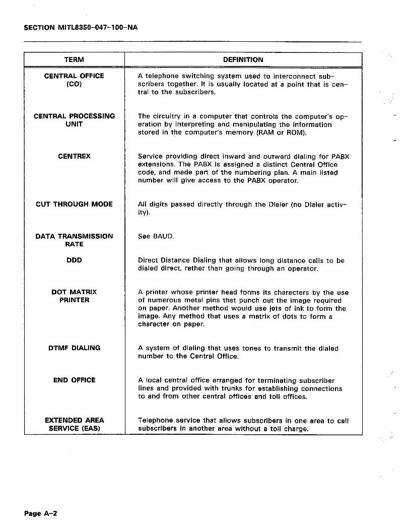
SECTlON MITL8350-047-l OO-NA
TERM
CENTRAL OFFICE (CO)
DEFINITION
A telephone switching system used to interconnect sub- scribers together. It is usually located at a point that is cen- tral to the subscribers.
CENTRAL PROCESSING UNIT
The circuitry in a computer that controls the computer’s op- eration by interpreting and manipulating the information stored in the computer’s memory (RAM or ROM).
CENTREX Service providing direct inward and outward dialing for PABX extensions. The PABX is assigned a distinct Central Office code, and made part of the numbering plan. A main listed number will give access to the PABX operator.
CUT THROUGH MODE All digits passed directly through the Dialer (no Dialer activ- ity).
DATA TRANSMISSION RATE
See BAUD.
DDD Direct Distance Dialing that allows long distance calls to be dialed direct, rather than going through an operator.
DOT MATRIX PRINTER
A printer whose printer head forms its characters by the use of numerous metal pins that punch out the image required on paper. Another method would use jets of ink to form the image. Any method that uses a matrix of dots to form a character on paper.
DTMF DIALING A system of dialing that uses tones to transmit the dialed number to the Central Office.
END OFFICE A local central office arranged for terminating subscriber lines and provided with trunks for establishing connections to and from other central offices and toll offices.
EXTENDED AREA Telephone service that allows subscribers in one area to call SERVICE (EAS) subscribers in another area without a toll charge.
Page A-2

SECTION MITL8350-047-l QO-NA
TERM
FOREIGN EXCHANGE (FW
DEFINITION
A classification of subscriber service that indicates service from any other central office other than the central office that would normally serve a subscriber. For example, a tele- phone in N.Y. has a Washington number assigned to it.
GROUND START A method of signaling to the Central Office. This signaling requires that a ground be applied to the RING side of the Line to indicate an Off-hook condition.
HERTZ (Hz)
INTERCONNECT
A term adapted as a unit of frequency preferred for world wide standardization and replacing “cycles per second”. 1000 Hz = 1000 cycles per second.
Companies other than the main telephone companies that supply telecommunications service and equipment.
KEY SYSTEM A versatile switching system located on the customer’s premises consisting of one or more multi-button telephone sets and associated equipment. Permits the mutual access to and control of several central office lines.
LINE An installed telephone with its associated wiring and auxil- iary equipment. Also referred to as a station or extension.
LOOP START A method of signaling the Central Office. This signaling re- quires that a termination be placed across the Tip and Ring to indicate an off-hook condition to the Central Office.
MAIN DISTRIBUTION FRAME
A frame where cables terminate for cross-connecting to a central office or private automatic branch exchange, equip- ment and connections to lines.
MEMORY The part of a computer where information can be stored, in binary form, and retrieved at any time.
OFF PREMISE A line connected to the PABX that is at a location other than EXTENSION (OPX) the location of the PABX.
Page A-3

SECTION MITL8350-047-l OO-NA
TERM
OFFICE CODE NW
OTHER COMMON CARRIER (OCC)
PRIVATE AUTOMATIC
BRANCH EXCHANGE (PABX)
PRIVATE BRANCH EXCHANGE (PBX)
ROM
DEFINITION
Any of the 792 codes that can be used as an address for a 10,000 line unit of Central Office.
A telephone system that provides long distance calls via other than normal carrier facilities, usually at a lower rate.
A telephone system located on the customer’s premises (Private Exchange), that allows calling between extensions without the assistance of an operator (Automatic), and hav- ing trunks going to the central office (Branch).
The same as PABX above, with the exception that an atten- dant (operator) is required to process calls.
Read Only Memory, a memory storage chip that may be programmed by someone other than the manufacturer. This chip can only be programmed once, and becomes a perma- nent modification when the process is completed.
RAM Random Access Memory, a section of memory that can be written to or read from at any point in time.
RESERVE POWER A backup DC battery system used to maintain normal switch operations in the event of a power failure.
ROTARY DIAL A dialing system that uses pulses to transmit the dialed number to the Central Office.
SEQUENTIAL ACCESS
A manner in which to read or write data as complete blocks of information, with each byte accessed in the exact order in which it was stored.
SOFTWARE Electrically stored memory, either on a permanent basis (ROM) or for a short time (RAM), that causes a computer type system to operate (a set of instructions).
SPEED CALLING A method of automatically completing a call to a subscriber by use of Speed Dialing.
Page A-4
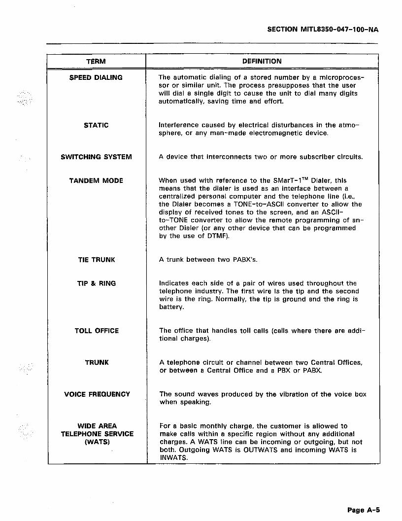
SECTION MITL8350-047-l OO-NA
TERM
SPEED DIALING
DEFINITION
The automatic dialing of a stored number by a microproces- sor or similar unit. The process presupposes that the user will dial a single digit to cause the unit to dial many digits automatically, saving time and effort.
STATIC Interference caused by electrical disturbances in the atmo- sphere, or any man-made electromagnetic device.
SWITCHING SYSTEM A device that interconnects two or more subscriber circuits.
TANDEM MODE When used with reference to the SMarT-lTM Dialer, this means that the dialer is used as an interface between a centralized personal computer and the telephone line (i.e., the Dialer becomes a TONE-to-ASCII converter to allow the display of received tones to the screen, and an ASCII- to-TONE converter to allow the remote programming of an- other Dialer (or any other device that can be programmed by the use of DTMF).
TIE TRUNK
TIP & RING
A trunk between two PABX’s.
Indicates each side of a pair of wires used throughout the telephone industry. The first wire is the tip and the second wire is the ring. Normally, the tip is ground and the ring is battery.
TOLL OFFICE The office that handles toll calls (calls where there are addi- tional charges).
TRUNK A telephone circuit or channel between two Central Offices, or between a Central Office and a PBX or PABX.
VOICE FREQUENCY The sound waves produced by the vibration of the voice box when speaking.
WIDE AREA TELEPHONE SERVICE
(WATS)
For a basic monthly charge, the customer is allowed to make calls within a specific region without any additional charges. A WATS line can be incoming or outgoing, but not both. Outgoing WATS is OUTWATS and incoming WATS is INWATS.
Page A-5

SECTION MITL8350-047-l OO-NA
--- THIS PAGE INTENTIONALLY LEFT BLANK ---
; . .
d
Page A-6

SECTION MITL8350-047-l OO-NA
APPENDIX B
FCC INTERCONNECTION REQUIREMENTS
General
81.01 This equipment has been approved by the Federal Communica- tions Commission (FCC) as not being harmful to the telephone
network when connected directly to the telephone lines through the standard connection cabling provided with the unit. This section is applicable to telephone interconnection in the United States.
81.02 Prior to the interconnection of this equipment, the local tele- phone company is to be notified; inform the company that you
have FCC-registered equipment that you wish to connect to their trunks. Give them the following information:
0 The telephone number of the line that will connect to the unit. 0 The equipment being connected is a MITEL DATACOM INC.
model SMarT-lTM or model SMarT-IA Common Carrier Access Dialer and Call Controller.
l The FCC Registration Number for the SMarT-lTM or SMarT-lATM is EMP 85B-14558-LR-E
0 The FCC Ringer Equivalence Number (REN) which is 6.7B. 0 The Connector Jacks required are RJ31X.
CONNECTION LIMITATIONS
81.03 Due to the FCC Part 68 Rule, no connection can be made to party lines and to coin telephone service, This unit is designed
to be used on standard-device telephone lines. If there are any ques- tions about the telephone line, such as how many pieces of equipment may be connected to it, the telephone company will provide this information upon request.
NETWORK CHANGES
81.04 The telephone company may make changes to it’s communica- tion service; such changes may include the change of trunk
circuits, changes in the operational characteristics of its trunks, etc. Before doing this, however, the company shall provide official notifica- tion, so that the operation of the Dialer service will not be interrupted.
MAINTENANCE LIMITATIONS
B1.05 This equipment has been registered with the FCC for direct connection to the telephone network. Under the FCC program,
the user is restricted from making any changes or repairs and from performing any maintenance operations other than those specifically included in this document.
Page B-l

SECTION MITL8350-047-l OO-NA
B1.06 There are no user repairable parts within the unit. It is sealed against user maintenance. If opened, all warranties are voided.
81.07 No cabling or wiring changes within the unit are permitted by the user. Plug-ended cables, as detailed in this document, are
to be used for all external connections between the unit and the telephone company interface jack.
B1.08 Power supply components and cabling is only to be changed or maintained by MITEL DATACOM INC. or by an authorized agent
of MITEL DATACOM INC.
TROUBLE CORRECTIONS
B1.09 For all malfunctions, appropriate field service is provided by MITEL DATACOM INC. or its authorized agents.
DISCONNECTION
B1.10 If it is ever decided to permanently disconnect the SMarT-lTM or SMarT-lATM Dialer from the present line, please notify the
telephone company of this change.
Page B-2
SECTION MITL8350-047-1 OO-NA
APPENDIX C
DIAGRAMS AND ASCII TABLE
Cl.01 Figures Cl and C2 on the following pages are a block diagram and a simplified electrical diagram for the SMarT-lTM Dialer.
Table Cl is a listing of the standard 7-bit ASCII codes followed by the code equivalents. Table C2 contains Legal Dialer Programming Input Characters.
Page C-l

SECTIQN MITL8350-047-l OO-NA
- - > INPUT #1 >
RECJGEN. LINE CCT
#l < OUTPUT #l f
-i t-i
#3 OUTPUT #3
I I I I
- -
<
-I
> INPUT #4 > RECJGEN. LINE CCT
#4 < OUTPUT #4 <
c I ROM
BATTERY
FIGURE Cl: SMarT-lTM SYSTEM BLOCK DIAGRAM
Page C-2 b
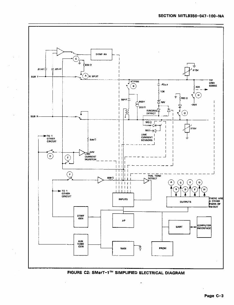
SECTION MITL8350-047-l OO-NA
.01&F
SUB T
.43PF
1OK
1 100 61
*-..
TIP GND SENSE
LINE I II
iNT I I r --------A I ----
1 I I I I I I I
I , I I I I
, , ,I, r ------- ---I
F
P
TO 1 OTHER CIRCUIl 1 ITHERE AP
UART
PROM
FIGURE C2: SMarT-lTM SIMPLIFIED ELECTRICAL DIAGRAM
Page C-3
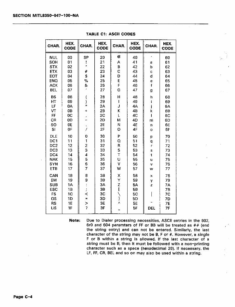
SECTION MITL8350-047-l OO-NA
TABLE Cl: ASCII CODES
HEX. CHAR. CODE CHAR. [;tE CHAR. J;;E CHAR. t;;i
NUL 00 SP 20 @ 40 ’ 60 SOH 01 ! 21 A 41 61 STX 02 rr 22 B 42 z 62 ETX 03 # 23 C 43 63 EOT 04 $ 24 D 44 : 64 ENQ 05 % 25 E 45 e 65 ACK 06 84 26 F 46 f 66 BEL 07 ’ 27 G 47 9 67
BS 08 HT 09 i
28 H 48 h 68 29 I 49 i 69
LF OA * 2A J 4A ’ 6A VT OB + 2B K 4B L 6B FF oc CR OD L
2c L 4c I 6C 2D M 4D ni 6D
SO OE ;
2E N 4E n 6E SI OF 2F 0 4F 0 6F
DLE 10 0 30 P 50 P 70 DC1 11 1 31 Q 51 cl 71 DC2 12 2 32 R 52 r 72 DC3 13 3 33 S 53 S 73 DC4 14 4 34 T 54 t 74 NAK 15 5 35 U 55 U 75 SYN 16 6 36 v 56 v 76 ETB 17 7 37 W 57 W 77
CAN 18 8 38 X 58 X 78 EM 19 9 39 Y 59 Y 79
SUB IA : 3A Z 5A z 7A ESC IB . 38 5B 78 FS 1c ;: 3c GS 1D
3 3D
c 5c 1 7c 5D 7D
RS 1E 3E A 5E - 7E us IF ? 3F _ 5F DEL 7F
Note: Due to Dialer processing necessities, ASCII entries in the 602, 6rO and 604 paramters of FF or BB will be treated as ## (end the string entry) and can not be entered. Similarly, the last character of the string may not be B, F or #. However, a single F or B within a string is allowed. If the last character of a string must be B, then it must be followed with a non-printing character such as a space (hexadecimal 20). If necessary, the LF, FF, CR, BEL and so on may also be used within a string.
Page C-4
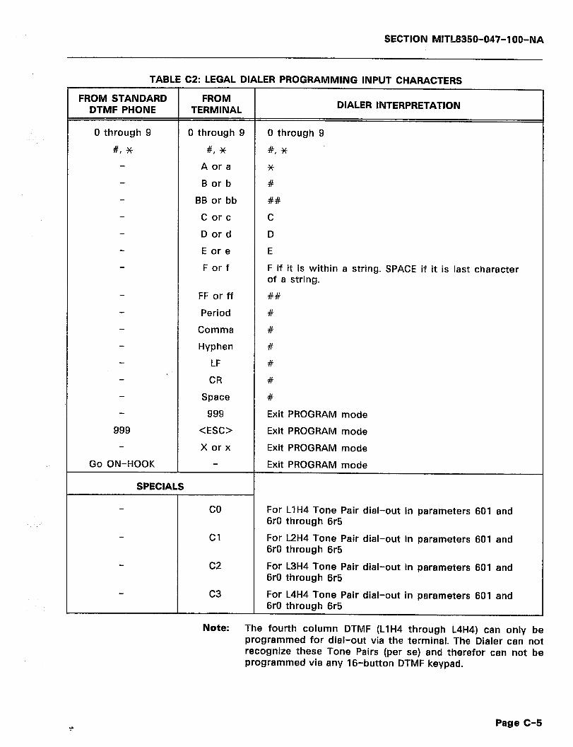
SECTlON MITLS350-047-100-NA
TABLE C2: LEGAL DIALER PROGRAMMING INPUT CHARACTERS
FROM STANDARD FROM DTMF PHONE TERMINAL DIALER INTERPRETATION
0 through 9 0 through 9 0 through 9
#, * #, * #,*
A or a *
B or b #
BB or bb ##
C or c C
D or d D
E or e E
F or f F if it is within a string. SPACE if it is last character of a string.
FF or ff ##
Period #
Comma #
Hyphen #
LF # I ‘.
CR #
Space #
999 Exit PROGRAM mode
999 <ESC> Exit PROGRAM mode
X or x Exit PROGRAM mode
Go ON-HOOK Exit PROGRAM mode
SPECIALS
co
Cl
c2
c3
For LlH4 Tone Pair dial-out in parameters 601 and 6rO through 6r5
For L2H4 Tone Pair dial-out in parameters 601 and 6rO through 6r5
For L3H4 Tone Pair dial-out in parameters 601 and 6rO through 6r5
For L4H4 Tone Pair dial-out in parameters 601 and 6rO through 6r5
Note: The fourth column DTMF (LlH4 through L4H4) can only be programmed for dial-out via the terminal. The Dialer can not recognize these Tone Pairs (per se) and therefor can not be programmed via any 16-button DTMF keypad.
Page C-5
SECTION MITL8360-047-IOO-NA
--- THIS PAGE INTENTIONALLY LEFT BLANK ---
a
d
.
Page C-6

SECTION MITL8350-047-l OO-NA
APPENDIX D OVERALL INDEX
CONTENTS PAGE CONTENTS PAGE
ACCESS CODE SEE GLOSSARY OF TERMS A-l
ACCESS CONTROL SEQUENCE (ACS) DEFINITION 19 ROUTEACCESS .__._._..__....._...__.....__....____ 19 SEE ROUTE SELECTION. 19 SEE TABLE 3 20
ACCESS CONTROL SEQUENCE CODES SEE TABLE 3 20
ACCESS METHOD NUMBER SEE ROUTE SELECTION 19
ACCESS NUMBER SEE STORE AND FORWARD 4 SEE ROUTE SELECTION 19
ACCOUNT NUMBER DEFINITION 22 SEE ROUTE SELECTION 19
e ACKNOWLEDGE TONES PARAMETERS 57 SEARCH TABLES . .._................ ._ 57 SEE DETAILED PROGRAMMING INSTRUCTIONS 57 STRINGS .._ _... ., _. .._..... 57
ACTION DIGITS SEETABLEZ....................................... 15 SEE TEMPLATE DESCRIPTION 14
ACTION ON DIALING SEE SIMPLIFIED PROGRAMMING 10
ADAPTIVE CALL ROUTING SEE DEFINITION OF TERMS 5
ADDITIONAL SEARCH INFORMATION CUT-THROUGH ..__ __ ._ ..__ 19 DO NOTHING _. .._ _.._ ____ _. 19 ENOUGH DIGITS _. __... _.... _._ _. 19 SEE OPERATION :_ 18 SPEED CALL .._ .._ _____ ___ .._....._ 18 SPEED CALL TRIGGER 18
ALTERNATE ROUTES SEE PARAMETERS 47
ALTERNATE ROUTING SEE LEAST CALL ROUTING 6
APPENDIX A GLOSSARY OF TERMS A-l
APPENDIX B CONNECTION LIMITATIONS B-l CONNECTOR JACKS B-l DISCONNECTION 8-2 FCC INTERCONNECTION REQUIREMENTS B-l FCC REGISTRATION NUMBER B-l MAINTENANCE LIMITATIONS B-l NETWORK CHANGES __.. ______.. __.____ ._ ., B-1 RINGER EQUIVALENCE NUMBER B-l TROUBLE CORRECTIONS B-2
APPENDIX C ASCII CODES _. _.__ __ _.....__...__. _.__ C-l ASCII TABLE C-4 DIAGRAMS __._.._,...____...._..__....._.,.__..__ C-l LEGAL DIALER PROGRAMMING INPUT CHARACTERS C-5 SMarT-1 SIMPLIFIED ELECTRICAL DIAGRAM . C-3 SMarT-1 SYSTEM BLOCK DIAGRAM C-2
APPENDIX D OVERALL INDEX : D-l
AREA CODE SEE DEFINITION OF TERMS 5 SEE GLOSSARY OF TERMS A-l
AREA CODE (NPA) SEE GLOSSARY OF TERMS A-l
ASCII SEE CALL RECORDS 23 SEE GLOSSARY OF TERMS . A-l
ASCII CHARACTERS SEE CALL RECORD FORMAT 29
ASCII CODES SEE APPENDIX C ................................... C-l SEE TABLE Cl ..................................... C-4
ASCII COMPATIBLE TERMINAL CONNECTIONS ..................................... 34 ERRORS .......................................... 36 PROCEDURE ....................................... 35 PROGRAMMING EXAMPLE ............................. 35 PROTOCOL ........................................ 34 SEE METHOD 1 ..................................... 34
ASCII TABLE SEE APPENDIX C ................................... C-4
AUTHORlZnTlON CODE SEESTOREAND FORWARD .............................. 4
AUTHORI2ATION NUMBER DEFINITION ....................................... 19 SEE ROUTE SELECTION ................................ 19
BASIC PROGRAMS SEE DETAILED PROGRAMMING .......................... 33
BATTERY BACK-UP SEE POWER ........................................ 6 SEE POWER FAILURE CONDITIONS ......................... 4
BAUD SEE GLOSSARY OF TERMS ............................ A-l
BEGIN DIALING AFTER 1ST DIGIT SEE EXAMPLE 3 ................................... 16 SEE SEARCH EXAMPLES .............................. 18
BUFFER SEE GLOSSARY OF TERMS ............................ A-l
CABLING SEE CONNECTIONS .................................
CALL COSTING SEE CALL RECORDING ................................. 5
CALL COSTING UNIT SEE CALL RECORDING OPERATION ........................ 23 SEE CONNECTING A STORAGE DEVICE ..................... 25
CALL RECORD FORMAT ASCII CHARACTERS .................................. 29 MITEL FORMAT ..................................... 26 RECORD EXAMPLES ................................ 30.31 SEE CALL RECORDING OPERATION ........................ 23 SMarT-1 FORMAT ................................... 28 SMarT-1 CALL RECORD FORMAT ......................... 29
CALL RECORDING CONNECTING A STORAGE DEVICE ........................ 24 SEE DEFINITION OF TERMS .............................. 5 SEE GLOSSARY OF TERMS ............................ A-l
CALL RECORDING OPERATION CALL COSTING UNIT ................................. 25 CALL RECORD FORMAT ............................... 25 CALL RECORDS ..................................... 23 CONCENTRATOR .................................... 25 CONNECTING A STORAGE DEVICE ........................ 24 MODEM .......................................... 25 SEE OPERATION .................................... 23
CALL RECORDS ASCII ............................................ 22 PAGE TITLE ....................................... 22 PRINTER.. ........................ __ .............. 22 RS-232 PORT ....................... .............. 22 SEE CALL RECORDING OPERATION ......... .............. 23 SEE OPERATION .................................... 23
CALL SEARCHING SEE DEFINITION OF TERMS .............................. 5 SEE GLOSSARY OF TERMS ............................ A-l
CENTRAL OFFICE (CO) SEE GLOSSARY OF TERMS ............................ A-2
Page D-l

SECTION MITL8350-047-l OO-NA
CONTENTS PAGE
CENTFIAL PROCESSING UNIT (CPU) SEE GLOSSARY OF TERMS
CENTREX SEE GLOSSARY OF TERMS
CENTREK ACCESS DIGIT SEE CENTAEX OPERATION SEE OTHER COMPARISONS
CENTRW COMPATIBLE SEE OEFINITION OF TERMS
CENTREK NUMBER SEE ROUTE SELECTION
CENTREX OPERATION CENTREX ACCESS DIGIT CENTREX STRING SEE OPERATION
CENTREX STRING DEFINITION SEE CENTREX OPERATION SEE ROUTE SELECTION
CHANGES TO DEFAULT DATA BASE SEE SIMPLIFIED OCC PROGRAMMING
CLONING CONDITIONS PROCEDURE REQUIRED EQUIPMENT SEE METHOD4 ,__.._..______. SEE PROGRAMMING METHOD 4
CLONING TIME SEE PROGRAMMING METHOD 4
CO SEE GLOSSARY OF TERMS
CO GENERATED DIAL TONE SEE OPTIONS
COMPARISON SEE SEARCHING
COMPARISON RESULTS SEE SEARCHING
COMPUTER SEE PROGRAMMING MEHTOD 1
COMPUTER CONNECTION SEE RS-232 PORT
CONCENTRATOR SEE CALL RECORDING OPERATION SEE CONNECTING A STORAGE DEVICE
CONFIGURATION SEE CALL RECORDING OPERATION SEE SIMPLIFIED PROGRAMMING
CONNECTING A STORAGE DEVICE CALL COSTING UNIT PRINTER SEE CALL RECORDING OPERATION TERMINAL
CONNECTION LIMITATIONS SEE APPENDIX B
CONNECTIONS EARTH GROUND POWER RS-232 PORT SEE FIGURE 2 SEE FIGURE 3 SEE FIGURE 4 SEE INSTALLATION SEE MODELS AVAILAELE . SEE TELEPHONE LINES
CONNECTOR JACKS SEE APPENDIX B
CONNECTOR PANEL SEE FIGURE 2
CUT-THROUGH MODE SEE ADDITIONAL SEARCH INFORMATION SEE GLOSSARY OF TERMS
A-2
A-2
23 16
6
19
23 23 23
19 23 19
11
59 59 59 59 33
33
A-2
13
14
14
33
25 25
23 10
25 24 24 24
E-1
7 7 7 8 6 9 7 5 7
B-l
8
18 A-2
DAMAGED GOODS SEE UNPACKING _........_ .., _...._ .._ ..__ 7
DATA FOR ALTERNATE ROUTES SEETABLE 8 .., _. _...._ .._ ..___ _. _.........._ _., 47
DATA FOR ROUTES SEE TABLE 8
DATA FOR TRUNKS SEE TABLE 8
DATA TRANSMISSION RATE SEE GLOSSARY OF TERMS
DATA TYPES PARAMETERS SEARCH TEMPLATES SEE ENTERING DATA STRINGS
DCE SEE RS-232 PORT
DDD SEE GLOSSARY OF TERMS
DDD ACCESSING PROCEDURE SEE ROUTE SELECTION
DDD ACCESSING USING ACS
CONTENTS PAGE
46
40-45
A-2
38 38 37 38
A-2
19
SEE ROUTE SELECTION 19 DDD NETWORK
SEE ROUTES _.. _... .._..... _... DEFAULT ACTIONS
SEE SIMPLIFIED PROGRAMMING DEFAULT CONFIGURATION
SEE METHOD 2 SEE SIMPLIFIED PROGRAMMING
DEFAULT DATA BASE SEE METHOD 2 .._..._.__... SEE SIMPLIFIED PROGRAMMING
DEFAULT DATA BASE CHANGE SEE SIMPLIFIED PROGRAMMING
DEFAULT DATA BASE LOADING PROCEDURE SEE METHOD 2
DEFAULT SETTINGS SEE TABLE 11
DEFAULT TRUNK AND DIALING SEE SIMPLIFIED OCC PROGRAMMING
DEFINITION OF TERMS ADAPTIVE CALL ROUTING AREA COOE .._ .._ .__ CALL RECORDING CALL SEARCHING CENTREX COMPATIBLE DTMF/ROTARY DIAL GROUND START/LOOP START LEAST COST ROUTING LINES
16
10
36 10
36 10
11
36
53-54
11
5 5 5 5
_._ 6 4 4 6 5
MODELS .......................................... 5 OFFICE CODE ....................................... 5 POWER ........................................... 6 POWER FAILURE CONDITIONS ............................ 4 RS-232 PORT ....................................... 5 SEE GENERAL OESCRll=rlON ............................. 3 SPEED CALL ........................................ 6 STOREANDFORWARD . . . . . . . . . . . . . . . . . . . . . . . . . . . . . . ...4 TRUNK SIDE DIALER 4 TWO (2) MODELS AVAILABLE ............................ 5 USER TRANSPARENT .................................. 4 VERSATILE PROGRAMMING .............................. 5
DESTINATION NUMBER DEFINITION ....................................... 19 SEE ROUTE SELECTION ................................ 19
DETAILED DESCRIPTION OPTIONS ......................................... 13 SEARCHING ....................................... 14 SEEOPERATION .................................... 13
DETAILED PROGRAMMING ACKNOWLEDGE TONES ............................... 57 DETAILED PROGRAMMING INSTRUCTIONS ................... 34 ENTERING DATA .................................... 37 INTRODUCTION ..................................... 33 METHOD 1 ........................................ 34 METHOD 2 ........................................ 36 PROGRAMMING METHOD 1 ................. ........... 33 PROGRAMMING METHOD 2 .................. .......... 33 PROGRAMMING METHOD 3 ............................. 33 PROGRAMMING METHOD 4 ............................. 33
Page D-2
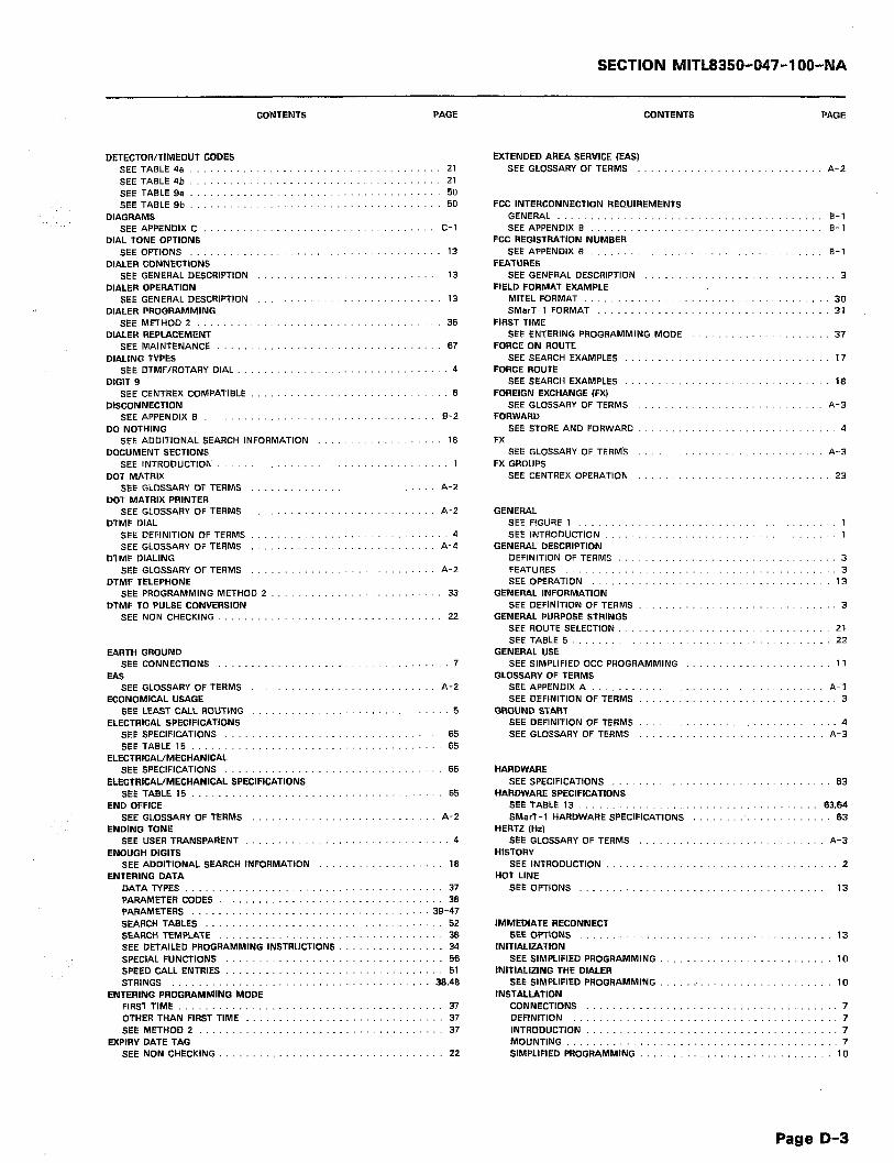
SECTION MITL8350-047-l OO-NA
CONTENTS PAGE CONTENTS PAGE
DETECTOR/TIMEOUT CODES EXTENDED AREA SERVICE (EAS) SEE TABLE46 _. __ ..__............ _..._..., __ ._ 21 SEE TABLE 4b __. ___...... _.......... _... __....... 21 SEE TABLE9e __...... _. _._ __........... 50 SEE TABLE 9b 50
DIAGRAMS
SEE GLOSSARY OF TERMS A-2
SEE APPENDIX C C-l DIAL TONE OPTIONS
SEE OPTIONS .__ . . . ..__._ .._...... 13 DIALER CONNECTIONS
FCC INTERCONNECTION REQUIREMENTS GENERAL SEE APPENDIX B
FCC REGISTRATION NUMBER SEE APPENDIX 6
FEATURES
B-1 B-I
E-1
SEE GENERAL DESCRIPTION 13 DIALER OPERATION
3
SEE GENERAL DESCRIPTION 13 DIALER PROGRAMMING
SEE METHOD 2 __.., __ _... __... __.. _.... 36 DIALER REPLACEMENT
SEE GENERAL DESCRIPTION FIELD FORMAT EXAMPLE
MITEL FORMAT SMarT-1 FORMAT
FIRST TIME
SEE MAINTENANCE 67 DIALING TVPES
SEE ENTERING PROGRAMMING MODE FORCE ON ROUTE
SEE SEARCH EXAMPLES FORCE ROUTE
30 31
37
SEE DTMF/ROTARY DIAL 4 DIGIT 9
17
SEE APPENDIX B E-2 DO NOTHING
SEE SEARCH EXAMPLES FOREIGN EXCHANGE (FX)
SEE GLOSSARY OF TERMS FORWARD
18 SEE CENTREX COMPATIBLE 6
DISCONNECTION A-3
SEE ADDITIONAL SEARCH INFORMATION 16 DOCUMENT SECTIONS
SEE STORE AND FORWARD FX
4
A-3 SEE INTRODUCTION _.._..._ ._ __........ _......... 1
DOT MATRIX
SEE GLOSSARY OF TERM’S FX GROUPS
SEE CENTREX OPERATION 23 SEE GLOSSARY OF TERMS A-2
DOT MATRIX PRINTER SEE GLOSSARY OF TERMS A-Z
DTMF DIAL GENERAL
SEE DEFINITION OF TERMS 4 SEE GLOSSARY OF TERMS A-4
DTMF DIALING SEE GLOSSARY OF TERMS A-2
DTMF TELEPHONE
1 1
3 3
: ‘13 SEE PROGRAMMING METHOD 2 33
DTMF TO PULSE CONVERSION SEE NON CHECKING. 22
EARTH GROUND
SEE FIGURE 1 SEE INTRODUCTION
GENERAL DESCRIPTION DEFINITION OF TERMS FEATURES SEE OPERATION
GENERAL INFORMATION SEE DEFINITION OF TERMS
GENERAL PURPOSE STRINGS SEE ROUTE SELECTION SEE TABLE 5
GENERAL USE SEE CONNECTIONS 7
EAS SEE GLOSSARY OF TERMS A-2
ECONOMICAL USAGE SEE LEAST CALL ROUTING ___. _. ___ .._ _. 5
ELECTRICAL SPECIFICATIONS
SEE SIMPLIFIED OCC PROGRAMMING GLOSSARY OF TERMS
SEE APPENDIX A SEE DEFINITION OF TERMS
GROUND START
SEE SPECIFICATIONS 65 SEETABLE . . . ..____._..._......_..... 65
ELECTRICAL/MECHANICAL
SEE OEFINITION OF TERMS SEE GLOSSARY OF TERMS
3
21 22
11
A-l 3
4 A-3
SEE SPECIFICATIONS 65 ELECTRICAL/MECHANICAL SPECIFICATIONS
SEETABLE ___.__......._...________..__.___..... 65 END OFFICE
HARDWARE SEE SPECIFICATIONS
SEE GLOSSARY OF TERMS
HARDWARE SPECIFICATIONS
HISTORY
SEE TABLE 13 SMerT-1 HARDWARE SPECIFICATIONS
HERTZ (Hz)
63
SEE USER TRANSPARENT .._ _.. _, . . . . . . . . 4 ENOUGH DIGITS
SEE GLOSSARY OF TERMS A-2 ENDING TONE
63.64 63
A-3
SEE ADDITIONAL SEARCH INFORMATION 16 SEE INTRODUCTION ENTERING DATA HOT LINE
DATATYPES _.. __....___. __ .,_._. _____. __._..... 37 PARAMETER CODES _. _........._ ,_ ._. ____... _....... 36 PARAMETERS 39-47 SEARCH TABLES __ ., .__.. _.. _._ .__ ____. _... _.._ 52 SEARCH TEMPLATE _..__., ..__._ _..__.. _._ 36 SEE DETAILED PROGRAMMING INSTRUCTIONS 34 SPECIAL FUNCTIONS . 56 SPEED CALL ENTRIES _._, _, _____ _._ __._ .__...._. 51 STRINGS . 3846
ENTERING PROGRAMMING MODE
SEE OPTIONS ___ ._ _... __
2
13
IMMEDIATE RECONNECT SEE OMIONS
INITIALIZATION SEE SIMPLIFIED PROGRAMMING
INITIALIZING THE DIALER SEE SIMPLIFIED PROGRAMMING
INSTALLATION
13
10
10
FIRST TIME 37 OTHER THAN FIRST TIME 37 SEE METHOD 2 _...__._. _.._ .._...___.... 37
MPIRV DATE TAG SEE NON CHECKING.................................. 22
CONNECTIONS DEFINITION INTRODUCTION . MOUNTING SIMPLIFIED PROGRAMMING
7 7 7 7
: ‘10
Page D-3

SECTION MITL8350-047-100-N/A
CONTENTS PAGE CONTENTS PAGE
UNPACKING INTENDED AUDIENCE
SEE INTRODUCTION INTERCONNECT
SEE GLOSSARY OF TERMS INTERNAL DIAL TONE
SEE OPTIONS INTRODUCTION
DOCUMENT SECTIONS GENERAL HISTORY INTENDED AUDIENCE OVERVIEW
7
2
A-3
13
2 2
JACKS SEE APPENDIX B B-l
KN SEE DEFINITION OF TERMS 5
MODEM SEE SPEED CALLS 22 SEE CALL RECORDING OPERATION 24
KEY SYSTEM MOUNTING SEE GLOSSARY OF TERMS A-3 SEE INSTALLATION 7
MOUNTING BRACKET SEE MOUNTING :. 7
LEAST CALL ROUTING SEE DEFINITION OF TERMS
LEAST COST ROUTING SEE CENTREX COMPATIBLE SEE DEFINITION OF TERMS
LEGAL DIALER PROGRAMMING INPUT CHARACTERS SEE APPENDIX C SEE TABLE C2
LINE SEE DEFINITION OF TERMS SEE GLOSSARY OF TERMS
LINE SPLIT SEE OPTIONS
LINE TYPES SEE GROUND START/LOOP START
LINES OPERATION SEE DEFINITION OF TERMS
LOADING DEFAULT DATA SEE SIMPLIFIED OCC PROGRAMMING
LOCAL PROGRAMMING SEE PROGRAMMING METHOD 2
LOGIC LEVELS SEE RS-232 CABLE
LOOP START SEE DEFINITION OF TERMS . SEE GLOSSARY OF TERMS i SEE GROUND START/LOOP START
MAIN DISTRIBUTION FRAME SEE GLOSSARY OF TERMS
MAINTENANCE DIALER REPLACEMENT GENERAL ._..... ___.. _.___
MAINTENANCE LIMITATIONS SEE APPENDIX I3
MANUAL ENTRY MODE SEE PROGRAMMING METHOD 2
MECHANICAL SPECIFICATIONS SEE SPECIFICATIONS SEE TABLE 15
MEMORY SEE GLOSSARY OF TERMS
MEMORY RETENTION SEE POWER FAILURE CONDITIONS
METHOD 1
6
6 6
C-l c-5
5 A-3
13
A-3
67 67
B-l
33
65 65
A-3,
4
SEE DETAILED PROGRAMMING .......................... 34 ASCII COMPATIBLE TERMINAL ........................... 34
METHOD 2 411 AND 911 PROGRAMMING DEFAULT CONFIGURATION
36 36
DEFAULT DATA BASE DEFAULT DATA BASE LOADING PROCEDURE DIALER PROGRAMMING ENTERING PROGRAMMING MODE. SEE DETAILED PROGRAMMING
METHOD 3 SEE ENTERING DATA TANDEM MODE
METHOD 4 CLONING . . . . . . . . . . . . . . . . . . . . . . . _. PROCEDURE .._ . . _.... ., SEE DETAILED PROGRAMMING INSTRUCTIONS SEE ENTERING DATA
MITEL FORMAT EXAMPLE . ..___ _.. _. ._ .__ ___ ., __. 30 SEE CALL RECORD FORMAT _, _. ._.._.... _._ _, 26 SEETABLE 6 . .._ ._ __.._ ..__ _. _.. _. 27
MODELS AVAILABLE
36 36 36 37 36
56 56
59 60
*
34 59
NETWORK CHANGES SEE APPENDIX B
NNX SEE GLOSSARY OF TERMS
NON CHECKING SEE NOT ON NETWORK (NON) CHECKING
NOT ON NETWORK (NON) CHECKING DTMF TO PULSE CONVERSION EXPIRY DATE TAG NON TONE .._ _. SEARCH TABLES _...__ _, _. SEE OPERATION
NON TONE SEE NOT ON NETWORK (NON) CHECKING
NORMAL OPERATION SEE OPTIONS
NPA
B-l
A-4
22
13
SEE GLOSSARY OF TERMS A-l NPA NUMBERS
SEE AREA CODE NUMBER OF LINES
SEE MODELS AVAILABLE NXX NUMBERS
SEE GLOSSARY OF TERMS SEE OFFICE CODE
5
5
A-4 5
SEE GLOSSARY OF TERMS A-4 OCC HOT LINE
SEE OPTIONS . . . . . .._ __......_... __. 13 OCC NETWORK
SEE ROUTES _...... ___ .._ OFF PREMISE MTENSION (OPX)
SEE GLOSSARY OF TERMS OFFICE CODE (NNX)
SEE OEFINITION OF TERMS
16
A-3
5 A-4 SEE GLOSSARY OF TERMS
OPEFtATION ADDITIONAL SEARCH INFORMATION 16 CALL RECOROING OPERATION 23 CALL RECORD FORMAT 25 CALL RECORDS 23 CENTREX OPERATION 23 DETAILED DESCRlmlON 13 GENERAL OESCRIFTION 13 INTRODUCTION 13 NOT ON NETWORK (NON) CHECKING : 22 OTHER COMPARISONS 16 ROUTE SELECTION 19
Page D-4
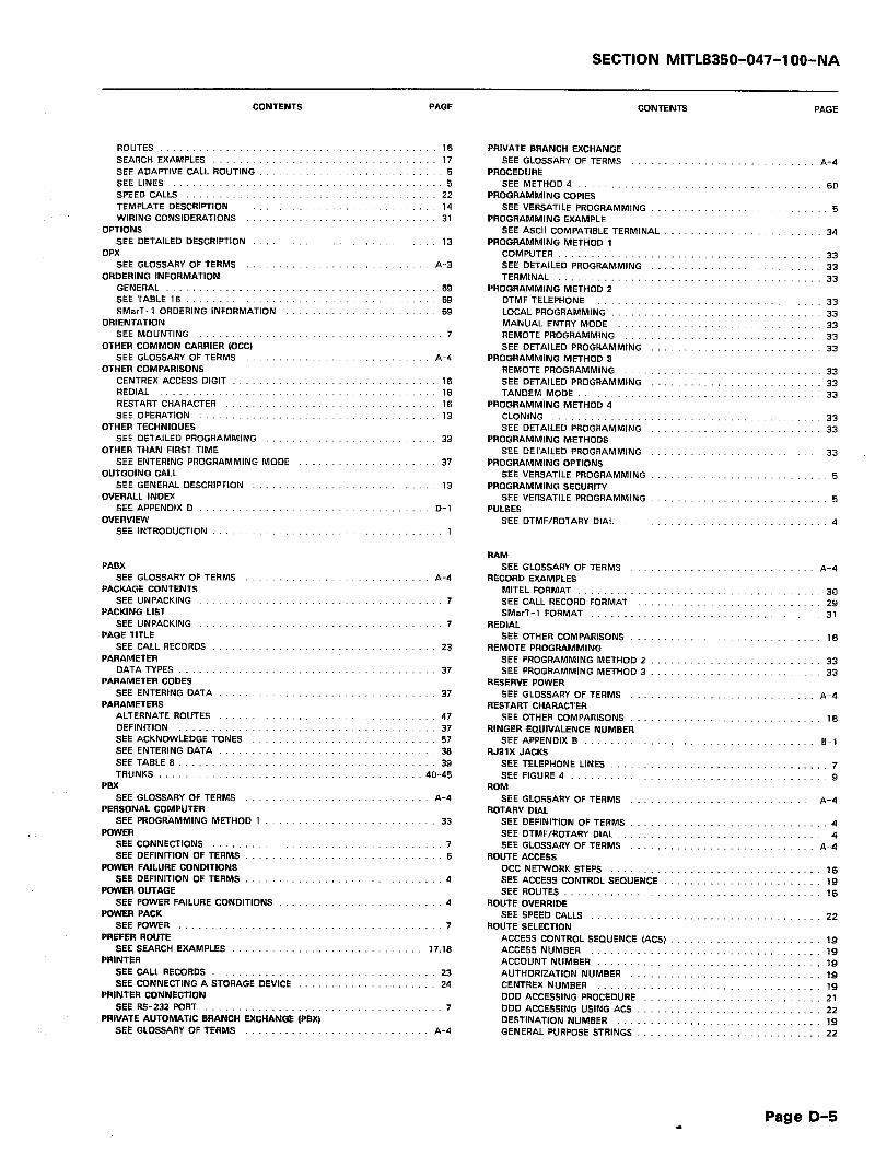
SECTION MITL8350-047-1 OO-NA
ROUTES SEARCH EXAMPLES SEE ADAPTIVE CALL ROUTING SEE LINES SPEED CALLS TEMPLATE DESCRIPTION WIRING CONSIDERATIONS
OPTIONS SEE DETAILED DESCRIPTION
CONTENTS PAGE CONTENTS PAGE
OPX 13
SEE GLOSSARY OF TERMS A-3 ORDERING INFORMATION
GENERAL ._ .._ _____ _. __. SEE TABLE 16 SMerT-1 ORDERING INFORMATION
ORIENTATION SEE MOUNTING
OTHER COMMON CARRIER (OCC) SEE GLOSSARY OF TERMS
OTHER COMPARISONS CENTREX ACCESS DIGIT REDIAL RESTART CHARACTER SEE OPERATION
OTHER TECHNIQUES SEE DETAILED PROGRAMMING
OTHER THAN FIRST TIME SEE ENTERING PROGRAMMING MODE
OUTGOING CALL SEE GENERAL DESCRIPTION
OVERALL INDEX SEE APPENDIX D
OVERVIEW SEE INTRODUCTION
PABX SEE GLOSSARY OF TERMS
PACKAGE CONTENTS SEE UNPACKING .._ _. ___ .__
PACKING LIST SEE UNPACKING
PAGE TITLE SEE CALL RECORDS
PARAMETER DATATYPES .._ __.... _. __... ,_.
PARAMETER CODES SEE ENTERING DATA
PARAMETERS ALTERNATE ROUTES DEFINITION SEE ACKNOWLEDGE TONES SEE ENTERING DATA SEE TABLE 6 TRUNKS ..__..... __ ._ .._ __.,
PBX SEE GLOSSARY OF TERM5
PERSONAL COMPUTER SEE PROGRAMMING METHOD 1
POWER SEE CONNECTIONS SEE DEFINITION OF TERMS
POWER FAILURE CONDITIONS SEE DEFINITION OF TERMS
POWER OUTAGE SEE POWER FAILURE CONDITIONS
POWER PACK SEE POWER
PREFER ROUTE SEE SEARCH EXAMPLE5
PRINTER SEE CALL RECORDS SEE CONNECTING A STORAGE DEVICE
PRINTER CONNECTION SEE RS-232 PORT
PRIVATE AUTOMATIC BRANCH EXCHANGE (PBX) SEE GLOSSARY OF TERMS
16 17
5 .-. 5
22 14 31
69 69 69
7
A-4
37
13
D-l
A-4
7
7
23
37
37
47 37 57 38 39
40-45
A-4
33
7 6
4
4
7
17.16
23 24
7
A-4
PRIVATE BRANCH EXCHANGE SEE GLOSSARY OF TERMS A-4
PROCEDURE SEE METHOD4 _......__ __....... _..... _..... .__ 60
PROGRAMMING COPIES SEE VERSATILE PROGRAMMING 5
PROGRAMMING EXAMPLE SEE ASCII COMPATIBLE TERMINAL . 34
PROGRAMMING METHOD 1 COMPUTER _...... __ ._ _.......... ___ _..... _. 33 SEE DETAILED PROGRAMMING 33 TERMINAL . . . . . . . _.......... __ 33
PRDGRAMMING METHOD 2 DTMF TELEPHONE 33 LOCAL PROGRAMMING 33 MANUAL ENTRY MODE 33 REMOTE PROGRAMMING 33 SEE DETAILED PROGRAMMING 33
PROGRAMMING METHOD 3 REMOTE PROGRAMMING 33 SEE DETAILED PROGRAMMING 33 TANDEM MODE . . . . . . . . . . . 33
PRDGRAMMING METHOD 4 CLONING .._ _. ._ _..... _......... 33 SEE DETAILED PROGRAMMING 33
PROGRAMMING METHODS SEE DETAILED PROGRAMMING 33
PROGRAMMING OPTIONS SEE VERSATILE PROGRAMMING 5
PROGRAMMING SECURITY SEE VERSATILE PROGRAMMING 5
PULSES SEE DTMF/ROTARY DIAL. 4
RAM SEE GLOSSARY OF TERMS A-4
RECORD EXAMPLES MITEL FORMAT 30 SEE CALL RECORD FORMAT 29 SMerT-1 FORMAT 31
REDIAL SEE OTHER COMPARISONS 16
REMOTE PROGRAMMING SEE PROGRAMMING METHOD 2 33 SEE PROGRAMMING METHOD 3 33
RESERVE POWER SEE GLOSSARY OF TERMS A-4
RESTART CHARACTER SEE OTHER COMPARISONS 16
RINGER EQUIVALENCE NUMBER SEE APPENDIX B B-1
RJBlX JACKS SEE TELEPHONE LINES , . 7 SEE FIGURE4 . . . . _. ._...... ___ ___........ 9
ROM SEE GLOSSARY OF TERM5 A-4
ROTARV DIAL SEE DEFINITION OF TERM5 4 SEE DTMF/ROTARY DIAL 4 SEE GLOSSARY OF TERMS A-4
ROUTE ACCESS OCC NETWORK STEP5 . 16 SEE ACCESS CONTRDL SEQUENCE . 19 SEEROUTES...................................... 16
ROUTE OVERRIDE SEE SPEED CALLS . 22
ROUTE SELECTION ACCESS CONTROL SEQUENCE (ACS) 19 ACCESS NUMBER . 19 ACCOUNT NUMBER __....... _..__.._. ___ .,_ 19 AUTHORIZATION NUMBER . 19 CENTREX NUMBER . . 19 DDD ACCESSING PROCEDURE 21 DDD ACCESSING USING ACS 22 DESTINATION NUMBER . 19 GENERAL PURPOSE STRINGS 22
Page D-5

SECTION MITL8350-047-l OO-NA
CONTENTS PAGE CONTENTS PAGE
SEE OPERATION SEE TABLE 3 SEE TABLE 4a SEE TABLE 4b SEE TABLE 5 TYPICAL CARRIER ACCESS EXAMPLE
ROUTES ODD NETWORK .._...__..__. OCC NETWORK ROUTE ACCESS SEE OPERATION SEE PARAMETERS
ROUTING SEE LINES
ROUTING DATA SEE LINES
ROUTING DECISIONS SEE CALL SEARCHING
RS-232 CABLE SEE LOGIC LEVELS SEE WIRING CONSIDERATIONS
RS-232 INTERFACE CONNECTOR SEE FIGURE 3
RS-232 PIN-OUT SEE RS-232 INTERFACE CONNECTOR
RS-232 PORT SEE CALL RECORDS SEE CONNECTIONS SEE DEFINITION OF TERMS SEE SPECIFICATIONS
RS-232 PORT SPECIFICATIONS SEE SPECIFICATIONS SEE TABLE 14
SEARCH ACTION SEESEARCHING ., ____ ..__ __...__. __ ._ SEESEARCH TABLES _. __ .._ _.. ._. __
SEARCH EXAMPLES l+ CALLS TO CARRIER (EXAMPLE 1) 1-c CALLS TO CARRIER, 1+800 TO DOD (EXAMPLE 2) 1+ CALLS TO CARRIER, 1+600 TO DDD (EXAMPLE 4) BEGIN DIALING AFTER 1ST DIGIT (EXAMPLE 3) FORCE ROUTE __. ___ .__ .._ ..__ .._ PREFER ROUTE SEE OPERATION SELECT ROUTE TRIGGER CODE ._. _.. __ .._ .._ ___.
SEARCH TABLE DESCRIFTION .._
SEARCH TABLE CODING EXAMPLES .._ _.. _____ _. _. __
SEARCH TABLE ENTRIES SEETABLE .._..._....._.__..___.._..
SEARCH TABLE 801 AND 802 SEE ENTERING DATA
SEARCH TABLE 803 AND 823 SEE ENTERING DATA
SEARCH TABLE 804 AND 824 SEE ENTERING DATA .
SEARCH TABLE 807 AND 827 SEE ENTERING DATA
SEARCH TABLE 808 AND 828 SEE ENTERING DATA
SEARCH TABLE 810 AND 830 SEE ENTERING DATA
SEARCH TABLE 811 AND 831 SEE ENTERING DATA
SEARCH TABLES CODES ._____. ______ . ..__ .._ DEFAULT SElTlNGS SEE ACKNOWLEDGE TONES SEE ENTERING DATA SEE NON CHECKING SEESEARCHING . . . .._.___.__._ ___.._.. SEETABLE ._........................
5
5
5
32 31
6
a
23 7 5
63
63 65
14 53.54
17 17 18 18 16 16 17 16 16
14
52
53,54
55
55
55
56
56
56
56
: ‘55.56 52
57 52 22 14
53.54
SEARCH TEMPLATE DEFINITION SEE ENTERING DATA
SEARCH-TEMPLATES DATATYPES . ..____......
SEARCHING COMPARISON COMPARISON RESULTS SEARCH TABLES _.__.. _.. _. SEARCHING ACTION SEE DETAILED DESCRIPTION
SEARCHING ACTION SEE SEARCHING
SECURITY SEE STORE AND FORWARD
SECURITY ACCESS CODE SEE SIMPLIFIED OCC PROGRAMMING
SELECT ROUTE SEE SEARCH EXAMPLES
SEQUENTIAL ACCESS SEE GLOSSARY OF TERMS
SERVICE SEE MODELS
SIMPLIFIED DIALING SEE SPEED CALL
SIMPLIFIED ELECTRICAL DIAGRAM SEE FIGURE C2
SIMPLIFIED OCC PROGRAMMING SEE SIMPLIFIED PROGRAMMING ACTION ON DIALING SEE INSTALLATION SEE SIMPLIFIED OCC PROGRAMMING
SIMPLIFIED PROGRAMMING ACTION ON DIALING INITIALIZING THE DIALER SEE INSTALLATION SIMPLIFIED OCC PROGRAMMING
SMarT-1 CALL RECORD FORMAT FIELDS SEE TABLE 7
SMarT-1 FORMAT EXAMPLE SEE CALL RECORD FORMAT SEE TABLE 7
SMarT-1 HARDWARE SPECIFICATIONS SEE TABLE 13
SMerT-1 ORDERING INFORMATION SEE ORDERING INFORMATION
SMarT-1 SIMPLIFIED ELECTRICAL DIAGRAM SEE APPENDIX C SEE FIGURE C2
SMerT-1 SYSTEM BLOCK DIAGRAM SEE APPENDIX C SEE FIGURE Cl
SOFTWARE SEE GLOSSARY OF TERMS
SPECIAL FUNCTIONS CODING .._... _._ .._ SEE ENTERING DATA SEE TABLE 12
SPECIFICATIONS ELECTRICAL ELECTRICAL/MECHANICAL HARDWARE .__ .._ __ .____..._ ., MECHANICAL RS-232 PORT
SPEED CALL SEE ADDITIONAL SEARCH INFORMATION SEE DEFINITION OF TERMS
SPEED CALL ACTIVATION SEE SPEED CALL
SPEED CALL AREA SIZE SEE SPEED CALL
SPEED CALL ENTRIES CODES ..__ _.__ _,_ .._ ., SEE ENTERING DATA SEE TABLE 10
17
A-4
5
6
c-3
11 10 10
7
10 10 10 11
29
31 26 29
63.64
69
C-l c-3
C-l c-2
A-4
55 56 57
65 65 63 85 65
16 6
6 .-
6
51 51 51
Page D-6
SECTION MITUWO-047-1 OO-NA
CONTENTS PAGE CONTENTS PAGE
SPEED CALL TRIGGER SEE ADDITIONAL SEARCH INFORMATION 16
SPEED CALLING SEE GLOSSARY OF TERMS A-4
SPEED CALLS KEY .._ .._ ___ ___.........._ 22 ROUTE OVERRIDE __ ._ ___................. 22 SEE OPERATION ._ __ ____.................. 22
SPEED DIALING
TROUBLE CORRECTIONS SEE APPENDIX B
TROUBLESHOOTING GENERAL _.... __.. _...
TROUBLESHOOTING CHART SEE TABLE 17 SEE TROUBLESHOOTING
TRUNK
SEE GLOSSARY OF TERMS A-5 STATIC
SEE GLOSSARY OF TERMS TRUNK ACCESS
SEE GLOSSARY OF TERMS A-5 STORAGE DEVICE
SEE GENERAL DESCRIPTION TRUNK PROGRAMMING
SEE GENERAL DESCRIPTION TRUNK SIDE DIALER
CONNECTIONS SEE DEFINITION OF TERMS
TRUNK NPES
B-2
71
71-74 71
A-5
13
13 PRINTER. _. ..__ ___ __.._ ..__ 24 TERMINAL ._...... __ ._ ___ ___.........__ 24
STORE SEE STORE AND FORWARD 4
STORE AND FORWARD SEE DEFINITION OF TERMS 4
STRING DEFINITION 36
STRING DATA ENTRV
SEE GROUND START/LOOP START TRUNKS
SEE TABLE 6 TVPE OF LINES
SEE TABLE 9 49.50 STRING ENTRV EXAMPLE
SEE GENERAL OESCRll=rlON TYPE OF UNIT
SEE STRINGS ._ ___...... _.... 46 STRINGS
SEE APPENDIX B TYPICAL CARRIER ACCESS EXAMPLE ’
SEE ROUTE SELECTION
.,. 4 4
4
39-45
13
B-l
21 DATATYPES _. _...., ..__........... 37 SEE ACKNOWLEDGE TONES 57 SEE ENTERING DATA 48 SEETABLE 9....................................... 50 SEE TABLE 9a __...._ 50 SEETABLE9b . . . . . . . . . . . 50 STRING ENTRY EXAMPLE 46
SWITCHING SVSTEM
UNIT SIZE SEE MOUNTING
UNPACKING SEE INSTALLATION
USERTRANSPARENT
SEE GLOSSARY OF TERMS A-5 SYSTEM BLOCK DIAGRAM
SEE DEFINITION OF TERMS USOCRJ31X JACK AND CABLE ASSEMBLY
SEE FIGURE 4
....... 7
....... 7
....... 4
....... 9 SEE FIGURE Cl C-4
SYSTEM WIDE DATA PARAMETERS SEE TABLE 6................................----.-- 39
TANDEM MODE SEE GLOSSARY OF TERMS A-5 SEE METHOD 3 .._ _._ 56 SEE PROGRAMMING METHOD 3 33
TELEPHONE LINES
VERSATILE PROGRAMMING SEE DEFINITION OF TERMS
VOICE FREQUENCY SEE GLOSSARY OF TERMS
VOLTAGE REQUIREMENTS SEE POWER
.- 5
A-5
7
SEE CONNECTIONS .._ _____ ..__ 7 TEMPLATE
WATS
SEE TEMPLATE DESCRIPTION 14 TEMPLATE DESCRIPTION
SEE CENTREX OPERATION SEE GLOSSARY OF TERMS
WIDE AREA TELEPHONE SERVICE (WATS) SEE GLOSSARY OF TERMS
WIRING CONSIDERATIONS RS-232 CABLE SEE OPERATION
SEE OPERATION 14 TEMPLATE DIGITS
SEETABLE 1 _. ____.... __ _.., .._ ..____ .___ ._ _._ __ 15 SEE TEMPLATE DESCRIPTION. 14
TERMINAL
23 A-5
A-5
31 31
SEE CONNECTING A STORAGE DEVICE 24 SEE PROGRAMMING METHOD 1 33
TIE TRUNK SEE GLOSSARY OF TERMS A-5
TIP & RING SEE GLOSSARY OF TERMS A-5
TOLL OFFICE SEE GLOSSARY OF TERMS : A-5
TONES SEE DTMF/ROTARY DIAL 4
TRAFFIC STUDIES
1+ CALLS TO CARRIER SEE EXAMPLE 1 SEE SEARCH EXAMPLES
l+ CALLS TO CARRIER, 1+800 TO DDD SEE EXAMPLE 2 SEE SEARCH EXAMPLES
l+ CALLS TO CARRIER, l+BOO TO DDD SEE EXAMPLE 3 SEE SEARCH EXAMPLES
...... 17
...... 17
...... 17
...... 17
....... 16
....... 16
SEE CALL RECORDING .._. ___............ 5 TRANSFORMER
SEE POWER _. _..... _. ___ __.. ____ __________ ._ .._. 6 TRIGGER CODE
411 AND 911 PROGRAMMING SEE METHOD 2 . 34
SEE SEARCH EXAMPLES 16
Page D-7

SECTION MITL8350-047-l OO-NA
I
MlTtL ENGINEERING PRACTICE SECTION MITL8350-047-102-NA Issue 1, April 1986
SUPPLEMENT TO
GENERAL INFORMATION MANUAL
COMMON CARRlER ACCESS DIALER
AND CALL CONTROLLER
WITH
POSITIVE ACCOUNT VERIFICATION
0 - Copyright of MITEL DATACOM INC. 1986 TM - Trademark of MITEL DATACOM INC.
@ - Registered Trademark of MITEL CORPORATION

SECTION MITL8350-047-102-NA
--- THIS PAGE INTENTIONALLY LEFT BLANK ---
SECTION MITL8350-047-102-NA
NOTICE TO U.S. CUSTOMERS
The information contained in this document is believed to be accurate in all respects but is not warranted by MITEL DATACOM INC. The information is subject to change without notice and should not be construed in any way as a commitment by MITEL DATACOM INC. or any of its affiliates or subsidiaries. MITEL DATACOM INC. and its affiliates and subsidiaries assume no responsibility for any errors or omissions in this document. Revisions of this document or new editions of it may be issued to incorporate such changes.
WARNING
The SMarT-lTM Common Carrier Access and Call Controller (PAV) generates, uses, and can radiate radio frequency energy and, if not installed and used in accordance with the instructions manual, may cause interference to radio communications. It has been tested and found to comply with the limits for a Class A computing device pursuant to Subpart J of Part 15 of FCC Rules, which are designed to provide reasonable protection against such interference when operated’in a commercial environment. Operation of this equipment in a residential area is likely to cause interference, in which case the user, at his own expense, will be required to take whatever measures may be required to correct the interference.
Page i
SECTION MITL8350-047-102-NA
--- THIS PAGE INTENTIONALLY LEFT BLANK ---
Page ii
SECTION MITL8350-047-102-NA
NOTICE TO CANADIAN CUSTOMERS
The information contained in this document is believed to be accurate in all respects but is not warranted by MITEL DATACOM INC. The information is subject to change without notice and should not be construed in any way as a commitment by MITEL DATACOM INC. or any of its affiliates or subsidiaries. MITEL DATACOM INC. and its affiliates and subsidiaries assume no responsibility for any errors or omissions in this document. Revisions of this document or new editions of it may be issued to incorporate such changes.
WARNING
The Canadian Department of Communications label identifies certified equipment. This certification means that the equipment meets certain telecommunications network protec- tive, operational, and safety requirements. The Department does not guarantee that the equipment will operate to the user’s satisfaction.
Before installing this equipment, users should ensure that it is permissable to be connected to the facilities of the local telecommunications company. The equipment must also be installed using an acceptable method of connection. In some cases, the company’s inside wiring associated with a single line individual service may be extended by means of a certified connector assembly (telephone extension cord). The customer should be aware that compliance with the above conditions may not prevent degradation of service in some situations.
Repairs to certified equipment should be made by an authorized Canadian maintenance facility designated by the supplier. Any repairs or alterations made by the user to this equipment, or equipment malfunctions, may give the telecommunications company cause to request the user to disconnect the equipment.
Users should ensure, for their own protection, that the electrical ground connections to the power utility, telephone lines, and internal metallic water pipe system, if present, are connected together. This precaution may be particularly important in rural areas.
CAUTION
Users should not attempt to make such connections themselves, but should contact the appropriate electric inspection authority, or electrician, as required.
The Load Number (LN) assigned to each terminal device denotes the percentage of the total load, to be connected to a telephone loop, that is used by the device to prevent overload- ing. The termination on a loop may consist of any combination of devices subject only to the requirement that the total of the Load Numbers of all of the devices doesn not exceed 100. An alphabetic suffix is also specified in the Load Number and designates the appro- priate ringing type (A or B), if applicable. For example, LN = 20 A designates a Load Number of 20 and an ‘A’ type ringer.
Page iii
SECTION MITL8350-047-102-NA
--- THIS PAGE INTENTIONALLY LEFT BLANK ---
Page iv
SECTION MITL8350-047-102-NA
IMPORTANT NOTES
Please note that MITEL DATACOM INC. has set up a National Field Service number for technical and installation assistance located in Dallas, Texas. This number is 12141 386-9400 for U.S. customers only (outside of normal -working hours, a telephone answering service has been established for your convenience at this same number). For Canadian customers, please contact your local MITEL Regional Office.
The SMarT-lTM Dialer includes an on-board battery back-up system to prevent the loss of customer database. Besides protecting against loss of data during momentary power outages, this battery back-up should also provide sufficient memory retention to allow the Dialer to be programmed by the distributor and then transported to the cus- tomer’s site for installation. This battery back-up, however, is not intended for long storage periods and cannot be guaranteed to support memory for long periods of time.
As received from the factory, the Dialer battery is not guaranteed to have a full charge applied to it. In fact, the battery is likely to be only partially charged in view of the time in transit, and distributor storage time. No guarantee of any battery charge status can be made until the Dialer has been powered up for a period of time. A period of 24 hours is necessary to achieve a full charge on the battery.
Upon removal from its shipping carton, the Dialer should be powered up for a period of time and then “X INITIALIZED” to load the operating system and default database into memory. Initialization may only be performed with a DTMF telephone set and requires connection to a working telephone line or an acceptable substitute. Never rely on program- ming entered into a Dialer until it has been “X INITIALIZED” (see Page 19, para. 5.04). Note that there is a short tone burst heard in the earpiece of the phone upon initialization. This tone indicates a successful initialize sequence has occurred.
Once initialized, the Dialer should seldom ever have to be initialized again. There is a Load Default Data Command that will restore memory to the initialized state once a “X INITIALIZE” has been performed. Once initialized, the Dialer will also respond to input via the RS-232 Input.
REASONS FOR ADDITIONAL “?c INITIALIZE” OPERATIONS
Dialer has just been removed from storage or shipping carton.
No toneburst upon release of the x Key. Maybe the tone was missed - check carefully.
The program access codes have been deleted accidentally or the access codes have been changed and forgotten.
The Dialer has just been repaired.
Long storage times.
Loss of data retention. Investigate for reason!
Page v

SECTION MITL8350-047-102-NA
--- THIS PAGE INTENTIONALLY LEFT BLANK ---
Page vi
SECTION MITL8350-047-102-NA
COMMON CARRIER ACCESS DIALER AND CALL CONTROLLER
WITH POSlTlVE ACCOUNT VERIFICATION
CONTENTS
1.
2.
3.
4.
5.
6.
PAGE
1 INTRODUCTION ...................................... DOCUMENT OBJECTIVES ............................. 1 DOCUMENT OVERVIEW ............................... 1 INTENDED AUDIENCE ................................ 2 DOCUMENT HISTORY ................................ 2 READER COMMENTS ................................. 2 DOCUMENT CONVENTIONS ........................... 2
GENERAL DESCRIPTION ............................... 3 FEATURES AND CAPABILITIES .......................... 3 DIALER DESCRIPTION ................................ 3
SPECIFICATIONS .................................... 5 HARDWARE ........................................ 5 RS-232 PORT ...................................... 7 ELECTRICAL/MECHANICAL ..... .-. ..................... 7
UNPACKING, INSTALLATION AND ORDERING INFORMATION . . 9 SHIPPING AND RECEIVING ............................ 9
Unpacking.. ..................................... 9 Repacking ....................................... 9
INSTALLATION REQUIREMENTS ........................ 9 POWER REQUIREMENTS ............................. 12 MOUNTING ....................................... 12 CONNECTIONS .................................... 12
RS-232 Port Configuration ......................... 16 RJ31X USOC Jack and Cable ....................... 16
ORDERING INFORMATION ............................ 16
OPERATING DESCRIPTION ............................ 19 GENERAL ......................................... 19 INITIALIZING THE DIALER ............................ 19 SPECIFIC DEFAULTS ................................ 20
903 Default Command - Standard O.C.C. Dialer ......... 20 DEFAULT LISTING .................................. 20 USER OPERATION .................................. 22
DETAILED PROGRAMMING ............................ 23 INTRODUCTION .................................... 23
Page vii
SECTION MITL8350-047-102-NA
CONTENTS PAGE
7.
8.
9.
SPECIAL FUNCTIONS ................................ 23 SYSTEM WIDE PARAMETERS .......................... 26 TRUNK RELATED PARAMETERS ........................ 27 ROUTE RELATED PARAMETERS ........................ 29 SEARCH TABLE ZERO CHANGES ....................... 35
Default Addition ................................. 35 Action Digit Addition ............................. 35
SEARCH TABLE ONE ................................ 35 Action Digit Changes ............................. 35
STRING DATA ENTRY CHANGES ....................... 35 PROGRAMMING EXAMPLES ........................... 36
Assumptions ................................... 36 PAV LIST MAINTENANCE EXAMPLE ..................... 37 ENTERING SPEED CALLS ............................. 37 SEARCH TABLE PROGRAMMING CONSIDERATIONS ........ 39
Parameter OOOt .................................. 39
CONTROLLER MEMORY CAPACITY ...................... 41 MEMORY SPACE ESTIMATING METHOD ................. 41
TECHNICAL CIRCUIT DESCRIPTION ..................... 47 INTRODUCTION .................................... 47
PHYSICAL MAINTENANCE AND TROUBLESHOOTING ........ 49 PHYSICAL MAINTENANCE ............................ 49 TROUBLESHOOTING ................................ 49
APPENDIX A ....................................... A-l FCC INTERCONNECTION REQUIREMENTS ............... A-l CONNECTION LIMITATIONS ......................... A-l NETWORK CHANGES ............................... A-l MAINTENANCE LIMITATIONS ........................ A-l TROUBLE CORRECTIONS ............................ A-2 DISCONNECTION .................................. A-2
APPENDIX B ....................................... B-l OVERALL TOPICAL INDEX ........................... B-l
FIGURES PAGE
4-1, 4-2, 4-3, 4-4, 4-5, 4-6, 4-7, 6-1,
Equipment Unpacking and Repacking ............... 10 Multi-Unit Packing and Repacking ................. 11 Controller I/O Connections ....................... 13 Typical Controller Installation Configuration ......... 13 Typical Connection Configuration .................. 14 RS-232 Interface Connector ...................... 14 USOC RJBIX Jack and Cable Assy ................. 15 Terminal Data Verification Example ................ 25
7-1, Calculation Sht. 1 .............................. 44 7-2, Calculation Sht. 2 .............................. 44 7-3, Calculation Sht. 3 .............................. 45
Page viii
SECTION MITL8350-047-102-NA
TABLES PAGE
3-1, SMarT-I Hardware Specifications .................. $6 3-2, RS-232 Port Specifications ........................ 7 3-3, Electrical/Mechanical Specifications ................. 7 4-1, SMarT-1 Ordering Information .................... 1’7 5-1, Listing of 903 Defaults .......................... 21 6-1, System Special Parameters ..................... 23,24 6-2, System Wide Parameters ........................ 26 6-3, Trunk Related Parameters ...................... 27,28 6-4, Primary Route Related Parameters ............... 30,31 6-5, Alternate Route Related Parameters .............. 31,32 6-6, Search Table 1 Action Digit Changes ............... 35 6-7, String Data Entry Changes ....................... 36 6-8, Programming Examples (PAV) ................... 36,37 6-9, PAV List Maintenance Example .................... 37 6-10, Speed Call Entries ........................... 38,39
Page :ix
SECTION MITL8350-047-102-NA
--- THIS PAGE INTENTIONALLY LEFT BLANK ---
Page x

SECTION MIlL8350-047-102-NA
I. INTRODUCTION
DOCUMENT OBJECTIVES
1 .Ol This document contains all information that relates to the SMarT-I’” Common Carrier Access Dialer and Call Controller
with Positive Account Verification. The title of the Section is ‘Supplement to General Information Manual, SMarT-I’” Common Car- rier Access Dialer and Call Controller with Positive Account Verifica- tion’. For ease of reference, the Section can be noted by its MITEL Part Number ‘MITL8350-047-102-NA’. This part of the Section is an over- view of the contents of the document and outlines the intended au- dience.
1.02 From this point forward and for ease of understanding, the SMarT-1 tm Common Carrier Access Dialer and Call Controller
with Positive Account Verification will be referred to in text as the ‘Dialer’. Positive Account Verfication will be referred to in text as ‘PAV’.
DOCUMENT OVERVIEW
1.03 The document contains important notices to customers at the front on pages i through v. The first notice is for U.S. cus-
tomers. The second is for Canadian customers. The third is general. in nature and applies to all customers. If a particular notice does. not apply, that page containing the notice may simply be removed from the manual.
1.04 Following the notices is a general Table of Contents. This table lists the major parts of the Section, along with subheadingsin
the order that they appear within the Section. The manual is divided into 9 parts and two appendices.
1.05 This part is a general overview of the manual. The second part is a description of the features and capabilities of the Dialer.
The third lists all specifications for the Dialer.
1.06 The fourth part describes in detail, all procedures for receiving, shipping, unpacking, installation and connection for the Dialer.
This part is followed by an operating description. The sixth part out- lines programming of the Dialer for use as PAV. The seventh part describes the memory space of the Dialer, while the eighth part is intended to be a technical circuit description. The ninth and final part describes physical maintenance and troubleshooting.
1.07 The appendices provide additional information that may be of some use to the installer, programmer, or user of the Dialer.
The first appendix includes FCC information, while the second contains an overall index listing topics in alphanumeric order. This index is included to provide an easy reference guide in locating specific in- formation.
Page 1
SECTION MITL8350-047-102-NA
INTENDED AUDIENCE
1.08 This document is intended for use as a general information manual for the installer, programmer, and user of the SMarT-1’”
Common Carrier Access Dialer and Call Controller with Positive Ac- count Verification. The document does not attempt to teach program- ming concepts. It is assumed that the reader has some programming experience.
DOCUMENT HISTORY
1.09 This is the first formal issue of this document. It is a supple- ment to the ‘SMarT-I’” Common Carrier Access Dialer and Call
Controller, General Information’ manual, MITEL P/N ‘MITL8350-047- IOO-NA’. Subsequent issues will be provided as information is changed or upgraded. These subsequent issues will replace any previous issue.
READER COMMENTS
1.10 If the user has any comments or corrections that pertain to this document, please forward a reply in writing to MITEL Docu-
mentation Control in Ogdensburg, N.Y., U.S.A., quoting document num- ber ‘SECTION MITL8350-047-IOZ-NA’.
DOCUMENT CONVENTIONS
1.11 Throughout this manual, the following conventions will be used:
SYMBOL MEANING
. . . A horizontal ellipsis means that the preceding item may be repeated one or more times.
tI II
t I
A vertical ellipsis means that not all of the statements in a figure or an example are shown; their content is not important to the example.
Double square brackets in statement and format de- scriptions enclose items that are optional.
Braces enclose lists from which the user must choose one item. Each item is separated from the other by a comma ‘,‘.
<> The less than and greater than signs, used in statement and format descriptions, usually enclose a special key to be pressed, such as a carriage return <CR> key.
> The greater than sign, when appearing alone, indicates the terminal prompt as shown on the terminal display.
Terminal lines use two conventions. If the characters are printed in capitalized characters (upper case), the words are typed as listed. If they are printed in small characters (lower case), they require that some char- acter(s) be entered in their place.
SECTION MITL8350-047-102-NA
2. GENERAL DESCRIPTION
FEATURES AND CAPABILITIES
The SMarT-1’” Dialer has the following features and capabil- ities:
Compliance with FCC Parts 68 and 15
Four Line capacity for the SMarT-1’” unit (MITEL P/N 8350-005)
Two Line capacity for the SMarT-1A’” unit (MITEL P/N 8350-006)
CDR Output
Versatile Programming
Automatic Route Selection (ARS)
Up to 1,000 Speed Calls, depending on length of Speed Call
l Installer programmable, or 0 Customer programmable
Tone to Pulse Conversion
Pulse to Tone Conversion
Each Speed Call entry may contain its own unique Account Code
Account Code Verification (PAV) on a System wide basis
Programmable selection of Routes to use PAV
Safeguarding of Customer’s database program against inadver- tent erasure
Separate program entry to allow customer update and main- tenance of PAV lists
Progress tones programmable on a route by route basis
Progammable for Account Code change on Route change
SMDR Indication of Speed Call and its related Account Code number
In addition, the unit has the following convenience features:
l Useable with Centrex Lines l Useable behind a PBWPABX l Hot Line operation
DIALER DESCRIPTION
2.02 The SMarT-I’” PAV Dialer is a self-contained electronics unit that provides most of the functions of the standard SMarT-1’”
Dialer with four times the amount of memory. The Dialer with PAV does not allow search table #I to be used for screening destination numbers. It is reserved for the PAV list. For a description of the
Page 3
: . . . .
SECTION MITL8350-047-102-NA
standard Dialer, refer to the General Information Manual (P/N 8350-047-IOO-NA). In addition, the PAV Dialer provides the ability to verify user dialed account codes. Other noteable differences from the standard Dialer are:
1.
2.
3.
4.
5.
6.
The unit verifies Account Codes on a System wide basis. .
_. :::
Only routes that have Account Codes enabled use the verifiable code list. This allows the Dialer to be programmed to do tasks such as to force the verification of account codes on toll routed calls only.
The PAV Dialer reserves search table #l for the entry of ac- count codes only. This table cannot be used to screen destina- tion digits.
A two step operation is required to accomplish maior database changes such as default database loads, search table flushes, etc. This safeguards against the inadvertent erasure of a cus- tomer’s database program by programmers or installers.
The unit includes a separate programming access code so that the end-user or customer can update and maintain the PAV list.
The unit has provisions for the addition of programmable Pro- gress Tones (beeps heard in the user’s telephone receiver) on a route by route basis. These progress tones are IOOms in dura- tion and can be programmed in any number from none to eight for a specified event.
Note: The standard Dialer has progress tones (beeps). These tones mentioned above, are in addition to the standard Dailer tones.
7. The number of Account Code warning tones (similar to pro- gress tones, but 400ms in duration instead of looms) can be programmed on a route by route basis. The warning tones can be programmed in any number from 1 to 8 tones. These tones are issued to the user if an Account Code is not entered within the programmable timeout period.
8. The Dialer can be programmed to prompt the caller for a new Account Code if the primary carrier is unavailable and the call overflows to another route or carrier. This feature is valid for both automatic and user forced redials. If the call fails to the same route, the user will not be required to reenter the Account Code.
,
Page 4

, ,
SECTION MITL8350-047-102-NA
3. SPECIFICATIONS
HARDWARE
3.01 Table 3-l lists all of the hardware specifications for the SMarT- ltm Common Carrier Access Dialer and Call Controller with
Positive Account Verficication (PAV). These specifications apply to all models of the Controller (4- or Z-line units) unless otherwise noted.
Table 3-1, SMarT-1’” Hardware Specifications
SPECIFICATION
FCC RINGER EQUIVALENCE
IDLE LINE, LOOP START
RINGER IMPEDANCE: 15-60 Hz, 70-11OV 20-3500 Hz, IOV
RINGING SENSITIVITY: 15-60 Hz
LEAKAGE: Tip to Ring, IOOV Tip to Earth, 1OOV
OFF HOOK CURRENT
IDLE LINE, GROUND START
SENSING RESISTANCE: Tip to Earth
OPEN CIRCUIT VOLTAGE: Tip
GROUNDING VOLTAGE
TIME TO RECOGNIZE TIP-GROUND
RESISTANCE: Sending Ring-Ground
BATTERY FEED
OPEN CIRCUIT VOLTAGE
FEED RESISTANCE
BALANCE: DC
SHORT CIRCUIT CURRENT
TERMINATION
RESISTANCE: DC, 20 mA DC, 40 mA
AC, 300-3000 Hz
RETURN LOSS: 600 ohms, 20mA
OPERATING CURRENT
MIN.
IO 1
40
20 20
15
36
-22
-5
10
22
550
36
200 200 550
20
13
TYP.
40
-25
0
n/a
24
600
40
600
26
MAX.
0.7B
20
80
45
-28
+10
150
26
650
50
300 300 650
80
UNITS
KQ MO
Volts
Mn Mfi
mA
KB
Volts
Volts
ms
Volts
52
dB
mA
sl 0 D
dB
mA
Page 5 . .

SECTION MITL8350-047-102-NA
Table 3-l (Cont’d), SMarT-1 tm Hardware Specifications
SPECIFICATION
DIAL TONE
CO SIDE FEED: Gain 300 Hz
INTERNAL FEED: 350 Hz
DTMF RECEIVER
LEVEL
LEVEL DIFFERENCE
FREQ: To receive To not receive
DURATION
TIME BETWEEN TONES
ROTARY RECEIVER
MAKE IMPEDANCE
MAKE DURATION
BREAK IMPEDANCE
BREAK DURATION
RATE
DTMF SENDER
LEVEL
FREQUENCY
DURATION (Programmable)
ROTARY SENDER
TIMING (Programmable)
TIMING (At 60/40): Make Break
RATE (At 60/40)
INTERDIGIT PAUSE (Programmable)
OPERATING RANGE
TEMPERATURE
HUMIDITY
ALLOWABLE VOLTAGE: connected to any point
MIN.
-2
-20
-6
-1.5 -3.5
40
30
20
8
20
7
-8
-1.3
40
40/30
35 55
9.9
400
0
0
TYP.
0
n/a
-6
60
60/40
10
800
MAX.
+2
+3
+6
+I.5 +3.5
700
100
100
20
-3
+I.3
130
60/40
45 65
10.1
1300
55
85
300
UNITS
dB
darn?
dB
% %
ms
ms
fi
ms
KQ
ms
PPs
dBmT
%
ms
ms/ms
ms ms
PPs
ms
“C
%
Volts
j+ With reference to 600~ Termination.
Page 6
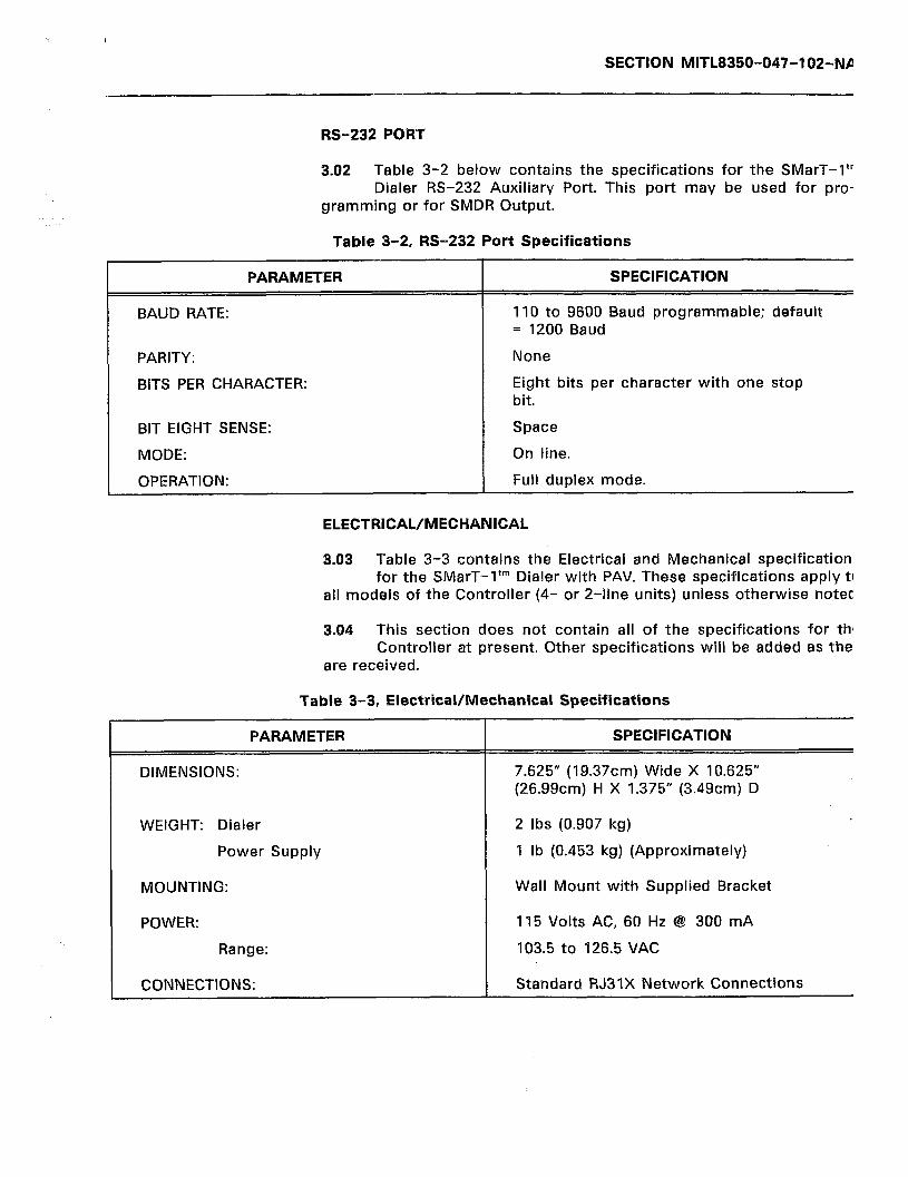
SECTION MITL8350-047-102-NA
PARAMETER
BAUD RATE:
PARITY:
BITS PER CHARACTER:
BIT EIGHT SENSE:
MODE:
OPERATION:
RS-232 PORT
3.02 Table 3-2 below contains the specifications for the SMarT-I’” Dialer RS-232 Auxiliary Port. This port may be used for pro-
gramming or for SMDR Output.
Table 3-2, RS-232 Port Specifications
SPECIFICATION
110 to 9600 Baud programmable; default = 1200 Baud
None
Eight bits per character with one stop bit.
Space
On line.
Full duplex mode.
ELECTRICAL/MECHANICAL
3.03 Table 3-3 contains the Electrical and Mechanical specifications for the SMarT-1’” Dialer with PAV. These specifications apply to
all models of the Controller (4- or 2-line units) unless otherwise noted.
3.04 This section does not contain all of the specifications for the Controller at present. Other specifications will be added as they
are received.
Table 3-3, Electrical/Mechanical Specifications
PARAMETER
DIMENSIONS:
WEIGHT: Dialer
Power
MOUNTING:
POWER:
Range:
CONNECTIONS:
SUPPlY
SPECIFICATION
7.625” (19.37cm) Wide X 10.625” (26.99cm) H X 1.375” (3.49cm) D
2 Ibs (0.907 kg)
1 lb (0.453 kg) (Approximately)
Wall Mount with Supplied Bracket
115 Volts AC, 60 Hz 8 300 mA
103.5 to 126.5 VAC
Standard RJ31X Network Connections
SECTION MITL8350-047-102-NA
3.05 The specifications in the Tables above are subject to change without notice. The inclusion of ‘n/a’ for a specific parameter
means that the specification is not available at the time of this pub- lication. It will be added at a later date.
Page 8

SECTION MITL8350-047-102-NA
4. UNPACKING, INSTALLATION AND ORDERING INFORMATION
SHIPPING AND RECEIVING
4.01 The SMarT-I’” Dialer with PAV is shipped in a single carton that contains the Dialer, the Power Supply, a Wall Mounting Bracket,
four RJ31X Cables and appropriate documentation. All of these items are protected within the carton by Styrofoam inserts.
Note: Some production units do not require the wall mounting brackets since these units are mounted to a wall by use of keyslots included on the unit case.
4.02 In some instances where more than one unit is shipped, a larger carton may be used that would contain five of the small-
er cartons. Each of the smaller cartons would contain the items listed in 4.01 above.
Unpacking
4.03 The procedure below lists steps to take when unpacking the equipment (refer to Figures 4-l and 4-2):
1) Open carton and remove contents.
2) Check each item removed for damage.
3) Check each item against the packing list.
4) Notify the vendor if any items are missing or appear to be damaged or defective.
Repacking
4.04 If an item is found to be defective or damaged and is to be returned to the vendor, it should be tagged and packaged to
prevent damage. If units are to be shipped from one location to another, these units should also be packaged in such a manner as to prevent damage. Figure 4-1 shows how the equipment was originally packed. This method of packaging should be followed as closely as possible.
4.05 If the original packaging material is no longer available, the returned parts should be wrapped in several layers of air-
cushion type of wrap, placed in a suitable container, and surrounded with paper to minimize the movement of the items.
INSTALLATION REQUIREMENTS
4.06 The SMarT-1’” Dialer is position independent. It may be mount- ed anywhere that will accommodate the unit size as listed in
the specifications in Table 3-3 on Page 7.
4.07 The Dialer will operate within a 0-55°C temperature and a
Page g
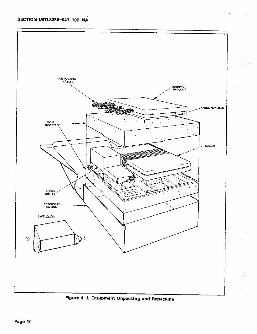
SECTION MITL8350-047-102-NA
RJ31WCA31A CABLES
DOCUMENTATIOI
DIALER
CARDBOARD
FLAP DETAIL
Figure 4-1, Equipment Unpacking and Repacking
Page 10

SECTION MlTL8350-047-102-NA
SINGLE UNIT CARTON
\ \ /-- /-- \ /--
\ _-- ‘Y--- /--
\ \ /.--
\ I- \
MULTI-UNIT CARTON
Figure 4-2, Multi-Unit Packing and Repacking
Page 11
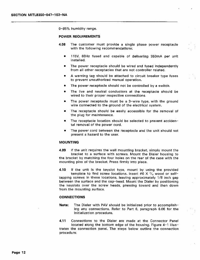
SECTION MITL8350-047-102-NA
O-85% humidity range.
POWER REQUIREMENTS
The customer must provide a single phase power receptacle with the following recommendations:
115V, 60Hz fused and capable of delivering 350mA per unit installed.
The power receptacle should be wired and fused independently from all other receptacles that are not controller related.
A warning tag should be attached to circuit breaker type fuses to prevent unauthorized manual operation.
The power receptacle should not be controlled by a switch.
The live and neutral conductors at the receptacle should be wired to their proper respective connections.
The power receptacle must be a 3-wire type, with the ground wire connected to the ground of the electrical system.
The receptacle should be easily accessible for the removal of the plug for maintenance.
The receptacle location should be selected to prevent acciden- tal removal of the power cord.
The power cord between the receptacle and the unit should not present a hazard to the user.
MOUNTING
4.09 If the unit requires the wall mounting bracket, simply mount the bracket to a surface with screws. Mount the Dialer housing to
the bracket by matching the four holes on the rear of the case with the mounting pins of the bracket. Press firmly into place.
4.10 If the unit is the keyslot type, mount by using the provided template to find screw locations. Insert #6 X 3/4 wood or self-
tapping screws in these locations, leaving approximately l/8 inch gap between the surface and the cap-head. Mount the Dialer by positioning the keyslots over the screw heads, pressing toward and then down from the mounting surface.
CONNECTIONS
Note: The Dialer with PAV should be ing any connections. Refer to initialization procedure.
initialized prior to accomplish- Part 6, paragraph 6.06 for the
4.11 Connections to the Dialer are made at the Connector Panel located along the bottom edge of the housing. Figure 4-l illus-
trates the connection panel. The steps below outline the connection procedure:
Page 12
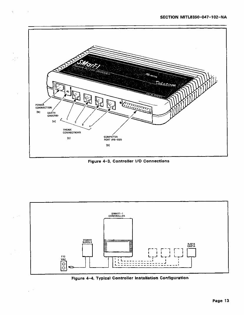
SECTION MITL8350-047-102-NA
TRUNK CONNECTIONS
[Cl /
COMPUTER PORT (RS-232)
[Dl
Figure 4-3, Controller I/O Connections
110 VAC
cl
0
0
SMART-1 CONTROLLER
POWER SUPPLY
RJ3lX CA31A
’ 1 L__-_______I ‘L______--____-___I I L-,-,___,,__,__,,,,_,,I
=n
Figure 4-4, Typical Controller Installation Configuration
Page 13
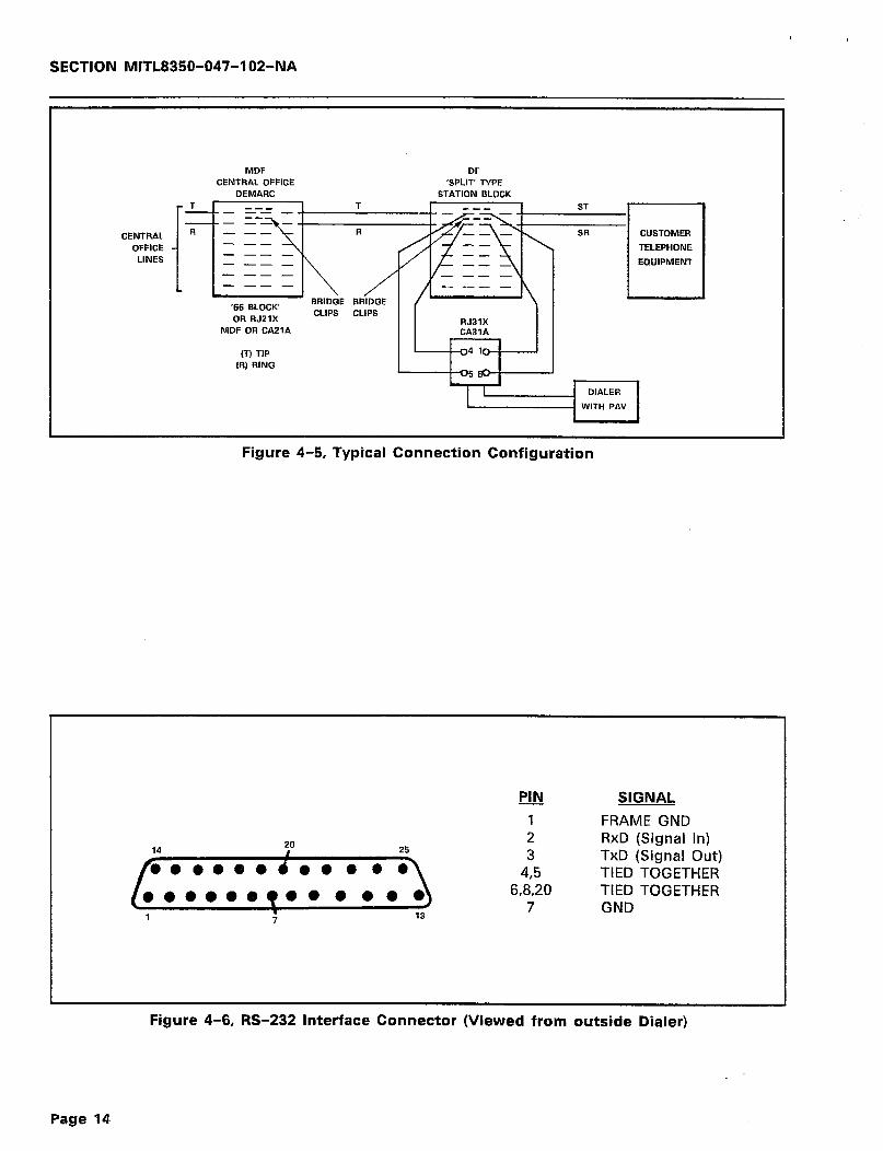
,
SECTION MlTL8350-047-102-NA
CENTRAL
OFFICE LINES
MDF DF CENTRAL OFFICE ‘SPLIT’ TYPE
DEMARC STATION BLOCK
i
T_ a-_ T _-_ ST --- -- _
- -- SR - -- - -- - - -- _ EQUIPMENT - -- - - -- _ - -- -
‘66 BLOCK BRIDGE BRIDGE
OR RJZlX CLIPS CLIPS 1 1
RJBlX I I MDF OR CAPlA
(T) TIP (R) RING
L--l-aI-,ld----J I
I I
Figure 4-5, Typical Connection Configuration
14 20
25
yrJ SIGNAL
1 FRAME GND 2 RxD (Signal in) 3 TxD (Signal Out)
4,5 TIED TOGETHER 6,8,20 TIED TOGETHER
7 GND
c
Figure 4-6, RS-232 Interface Connector (Viewed from outside Dialer) I
Page 14
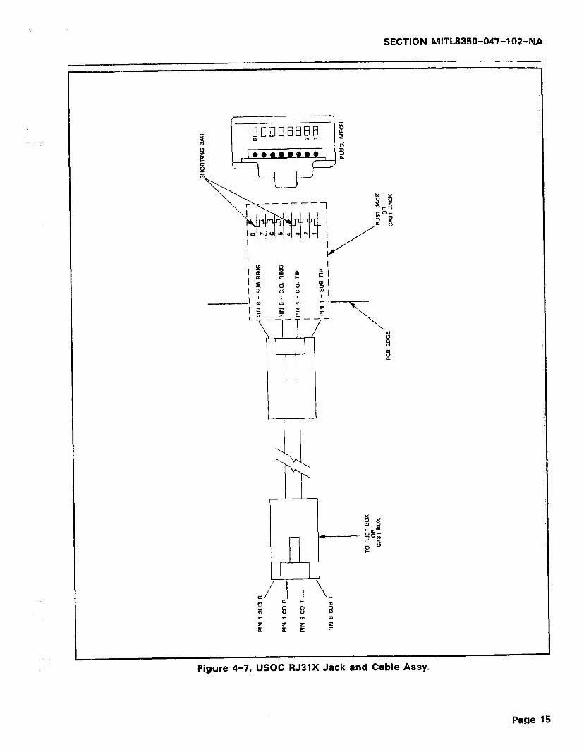
SECTION MITL8350-047-102-NA
1
I !-
Figure 4-7, USOC RJ3lX Jack and Cable ASSY.
Page 15

SECTION MITL8350-047-102-NA
1)
2) 3)
4)
5)
6)
7)
4.12
Refer to Figure 4-3. Connect a suitable Earth Ground to the screw mount [Al provided on the connector panel. This connec- tion MUST be made for the unit to function properly.
Plug the Power Pack jack into the Dialer power connection [Bl.
Plug the Power Pack AC line cord into a suitable (1 IOV-6OHz) AC receptacle.
Using the supplied RJ31X cables, insert one end of a cable in a jack on the Dialer [Cl.
Connect the other end of the cable used in step 4 to the Telco-supplied jack.
Repeat steps 4 and 5 above for the appropriate number of times depending upon the model of Dialer being installed (4- or 2-line units).
Connect a suitable terminal to the RS-232 Computer Port [Dl via a suitable cable. Configuration of this cable is described in paragraph 4.13 below.
This completes the mechanical installation of the SMarT-I’” Common Carrier Access Dialer and Call Controller. Continue by
programming the unit from a DTMF telephone attached to the Dialer or from the terminal.
RS-232 Port Configuration
4.13 The RS-232 Computer Port connector (refer to Figure 4-6) is a female connector configured as “DCE”. Only the TxD (pin 3), the
RxD (pin 2), and the GND (pin 1) lines are used by the Controller. Pins 4 through 6, 8, and 20 are shorted internally for the convenience of the user. This port is used for programming and call recording output.
4.14 During programming, a suitable terminal may be connected to this port. For call recording output, a suitable printer is con-
nected in place of the terminal. Refer to General Information Manual, Part 6 paragraph 6.02 for the configuration of the terminal or the printer.
RJ31X USOC Jack and Cable
4.15 Figure 4-7 illustrates the USOC RJ31X Connector and cable assembly as used by the Dialer. Figure 4-5 illustrates the in-
stallation wiring of the Telco-supplied RJ31X USOC jack and other connections from the Central Office. For the unit to operate properly, the bridge clips at the “split” type station block must be removed.
ORDERING INFORMATION
4.15 Table 4-l on the following page lists the part numbers and descriptions of items that can be ordered from MITEL DATA-
COM INC.
Page 16
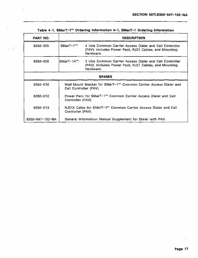
SECTION MITL8350-047-102-NA
Table 4-1, SMarT-It” Ordering Information 4-1, SMarT-1 Ordering Information
PART NO. I DESCRIPTION
8350-005 SMarT-1’“: 4 Line Common Carrier Access Dialer and Call Controller (PAV). Includes Power Pack, RJ31 Cables, and Mounting Hardware.
8350-006 SMarT-18’“: 2 Line Common Carrier Access Dialer and Call Controller (PAV). Includes Power Pack, RJ31 Cables, and Mounting Hardware.
SPARES
8350-010 Wall Mount Bracket for SMarT-I’” Common Carrier Access Dialer and Call Controller (PAV).
8350-012 Power Pack for SMarT-1’” Common Carrier Access Dialer and Call Controller (PAV).
8350-013 RJ31X Cable for SMarT-1’” Common Carrier Access Dialer and Call Controller (PAV).
8350-047-l 02-NA General Information Manual Supplement for Dialer with PAV.
Page 17

SECTION MITL8350-047-102-NA
--- THIS PAGE INTENTIONALLY LEFT BLANK ---
Page 18
SECTION MITL8350-047-102-NA
5. OPERATING DESCRIPTION
GENERAL
5.01 The primary function of the SMarT-1’” Common Carrier Access Dialer and Call Controller with Positive Account Verification is
to provide the ability to verify user dialed account codes when the Dialer is used as described in the General Information Manual (SECTION MITL8350-047-IOO-NA). This feature can be enabled or dis- abled by programming.
5.02 The PAV function provided by the Dialer lies in three distinct areas. These areas are:
0 Expanded memory enabling the Dialer to have up to 1000 Speed Calls and depending on memory use, storage of Account Codes.
0 The inclusion of additional programmable progress tones on a route by route basis and Account user.
Code warning tones for the
l Account Code verification against programmed Account Codes to eliminate unauthorized use of the facility. This verification also includes Call Detail Recording output.
5.03 The following descriptions outline typical operating modes for the SMarT-lTM Dialer with Positive Account Verification. These
operating modes are unique to this unit. Except as noted below, the General Information Manual applies in its entirety.
INITIALIZING THE DIALER
5.04 The Dialer is initialized in the same manner as the standard SMarT-lTM Dialer. The procedure for initialization listed below is
repeated from the General Information Manual to reduce cross refer- encing and to include the default command upon completion of ini- tialization.
1) 2)
3)
4)
5)
6)
7)
Connect an earth ground to the Dialer.
Connect a DTMF telephone or butt set to the subscriber side Tip & Ring leads of the Dialer.
Connect a standard telephone line or network to the C.O. side of the Dialer.
With the power to the Dialer disconnected, go off-hook.
While holding down the * key on the DTMF set, connect the power to the Dialer. A DTMF tone should be audible in the handset receiver.
Continue to hold the x key for 10 seconds or more after apply- ing power to the Dialer.
Release the x key. The unit should respond immediately with a short tone from the handset receiver. If the tone is not heard,
Page 19
I
SECTION MITL8350-047-102-NA
return to step 1 above and start over. The tone burst indicates that the Dialer is initialized and defaulted to its “standard” con- figuration. It also indicates that it is in the programming mode and awaiting a command.
5.05
1)
Once the above listed procedure has been completed, the user has only one option available. This is:
GO ON-HOOK: The Dialer is defaulted as a standard O.C.C. Dialer as noted in the General Information Manual. The only difference is that it is capable of up to 1,000 Speed Calls (with account codes). All of the programming information in the Gen- eral Information Manual applies to the Dialer in this configura- tion.
SPECIFIC DEFAULTS
5.06 The paragraphs that follow list specific defaults and values for the Dialer with PAV. Any parameters that are not listed appear
in the General Information Manual. They are also the same defaults as for the standard SMarT-lTM Dialer. For more information on these defaults, refer to the General Information Manual, Section 5.
903 Default Command - Standard O.C.C. Dialer
5.07 All defaults are unchanged from the standard SMarT-lTM unit defaults except that there are no Alternate Search Table entries.
Refer to the General Information Manual, Section 5, for a complete listing. Also refer to Table 5-3 of this manual for Speed Call and Account Code enhancements that are provided in the Expanded Mem- ory unit under the 903 default.
DEFAULT LISTING
5.08 Table 5-3 is a listing of the 903 defaults. In this listing, the reader will note that there are some enhancements that are
possible with the 903 defaults that are not included or possible with the “standard” SMarT-lTM Dialer. Once again, the General Information Manual (MITEL P/N 8350-047-IOO-NA) is applicable to all parameters and functions for the 903 command, but with the addition of the listed enhanced operation capabilities. Specifically, in the 903 “standard” mode, up to 1,000 Speed Call positions are now possible. Each Speed Call may now contain its own unique Account Code, if desired.
Page 20
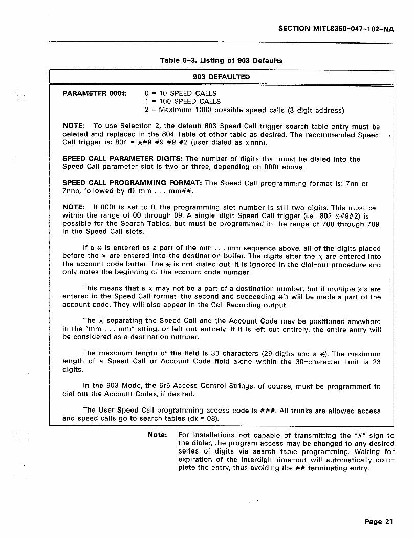
SECTION MITL8350-047-102-NA
Table 5-3, Listing of 903 Defaults
903 DEFAULTED
PARAMETER OOOt: 0 = 10 SPEED CALLS 1 = 100 SPEED CALLS 2 = Maximum 1000 possible speed calls (3 digit address)
NOTE: To use Selection 2, the default 803 Speed Call trigger search table entry must be deleted and replaced in the 804 Table ot other table as desired. The recommended Speed Call trigger is: 804 = #I9 #9 #9 #2 (user dialed as xnnn).
SPEED CALL PARAMETER DIGITS: The number of digits that must be dialed into the Speed Call parameter slot is two or three, depending on OOOt above.
SPEED CALL PROGRAMMING FORMAT: The Speed Call programming format is: 7nn or 7nnn, followed by dk mm . . . mm##.
NOTE: If OOOt is set to 0, the programming slot number is still two digits. This must be within the range of 00 through 09. A single-digit Speed Call trigger (i.e., 802 *#9#2) is possible for the Search Tables, but must be programmed in the range of 700 through 709 in the Speed Call slots.
If a x is entered as a part of the mm . . . mm sequence above, all of the digits placed before the * are entered into the destination buffer. The digits after the x are entered into the account code buffer. The x is not dialed out. It is ignored in the dial-out procedure and only notes the beginning of the account code number.
This means that a x may not be a part of a destination number, but if multiple X’S are i entered in the Speed Call format, the second and succeeding X’S will be made a part of the account code. They will also appear in the Call Recording output.
The x separating the Speed Call and the Account Code may be positioned anywhere in the “mm . . . mm” string, or left out entirely. If it is left out entirely, the entire entry will be considered as a destination number.
The maximum length of the field is 30 characters (29 digits and a x). The maximum length of a Speed Call or Account Code field alone within the 30-character limit is 23 digits.
In the 903 Mode, the 6r5 Access Control Strings, of course, must be programmed to dial out the Account Codes, if desired.
The User Speed Call programming access code is ###. All trunks are allowed access and speed calls go to search tables (dk = 08).
Note: For installations not capable of transmitting the “#” sign to the dialer, the program access may be changed to any desired series of digits via search table programming. Waiting for expiration of the interdigit time-out will automatically com- plete the entry, thus avoiding the ## terminating entry.
Page 21
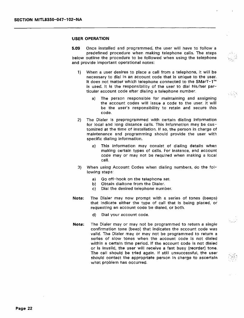
SECTION MITL8350-047-102-NA
USER OPERATION
5.09 Once installed and programmed, the user will have to follow a predefined procedure when making telephone calls. The steps
below outline the procedure to be followed when using the telephone and provide important operational notes:
; :.::.L .
1) When a user desires to place a call from a telephone, it will be necessary to dial in an account code that is unique to the user. It does not matter which telephone connected to the SMarT-I’” is used. It is the responsibility of the user to dial his/her par- ticular account code after dialing a telephone number.
:‘ a) The person responsible for maintaining and assigning
the account codes will issue a code to the user. It will be the user’s responsibility to retain and secure this code.
2) The Dialer is preprogrammed with certain dialing information for local and long distance calls. This information may be cus- tomized at the time of installation. If so, the person in charge of maintenance and programming should provide the user with specific dialing information.
a) This information may consist of dialing details when making certain types of calls. For instance, and account code may or may not be required when making a local call.
3) When using Account Codes when dialing numbers, do the fol- lowing steps:
Note:
Note:
a) Go off-hook on the telephone set. b) Obtain dialtone from the Dialer. c) Dial the desired telephone number.
The Dialer may now prompt with a series of tones (beeps) that indicate either the type of call that is being placed, or requesting an account code be dialed, or both.
d) Dial your account code. 1
.. .- The Dialer may or may not be programmed to return a single confirmation tone (beep) that indicates the account code was valid. The Dialer may or may not be programmed to return a series of slow tones when the account code is not dialed within a certain time period. If the account code is not dialed or is invalid, the user will receive a fast busy (reorder) tone. The call should be tried again. If still unsuccessful, the user should contact the appropriate person in charge to ascertain what problem has occurred.
Page 22

SECTION MlTL8350-047-102-NA
6. DETAILED PROGRAMMING
INTRODUCTION
6.01 The SMarT-I’” Common Carrier Access Dialer and Call Control- ler with Positive Account Verification (PAV) should be pro-
grammed according to normal site specific information. Refer to Sec- tion 5 of the Genera! Information Manual for detailed programming information and procedures in accomplishing programming. It is as- sumed that the user or programmer has read these sections and understands the programming methods.
6.02 Only those areas of special interest to Positive Account Ver- ification or those registers that are affected by PAV software
will be dealt with in the following tables and paragraphs.
SPECIAL FUNCTIONS
6.03 Table 6-l below lists System Special Parameters along with descriptions of each parameter. Special Function commands
that are preceded with a ‘942’ are actually two step operations. These commands require the entry of the ‘942’ followed by three more digits (903, 904, etc.) to select the command parameter. When ‘942’ is dialed, it is followed by a double progress tone (two beeps) in the receiver of the DTMF telephone, or by a <CR> (carriage return) on the display of the terminal. Dialing the next three digits will cause the receiver to emit another double progress tone, or the terminal to display another <CR>.
Table 6-1, System Special Parameters
ENTER
999
980mmddhhmm
DESCRIPTION
Exit program mode.
Enter Date and Time for Call Detail Record and Time-of-Day Access Control.
902 Enter Data Confirmation Mode. This parameter allows pro- grammed data to be read back for verification.
907
942903
942904
Exit Data Confirmation Mode. Return to program mode.
Load Factory Installed Default Database. This command will re-install all default database parameter settings and will de- lete any other programmed data.
Delete All Search Table Entries. CAUTION - This command deletes all data resident in the 801 through 835 Search Ta- bles. The Controller cannot operate without data entered in these tables. The only reason for erasing this data is if the user wishes to restart with an entirely new data program
(continued)
Page 23
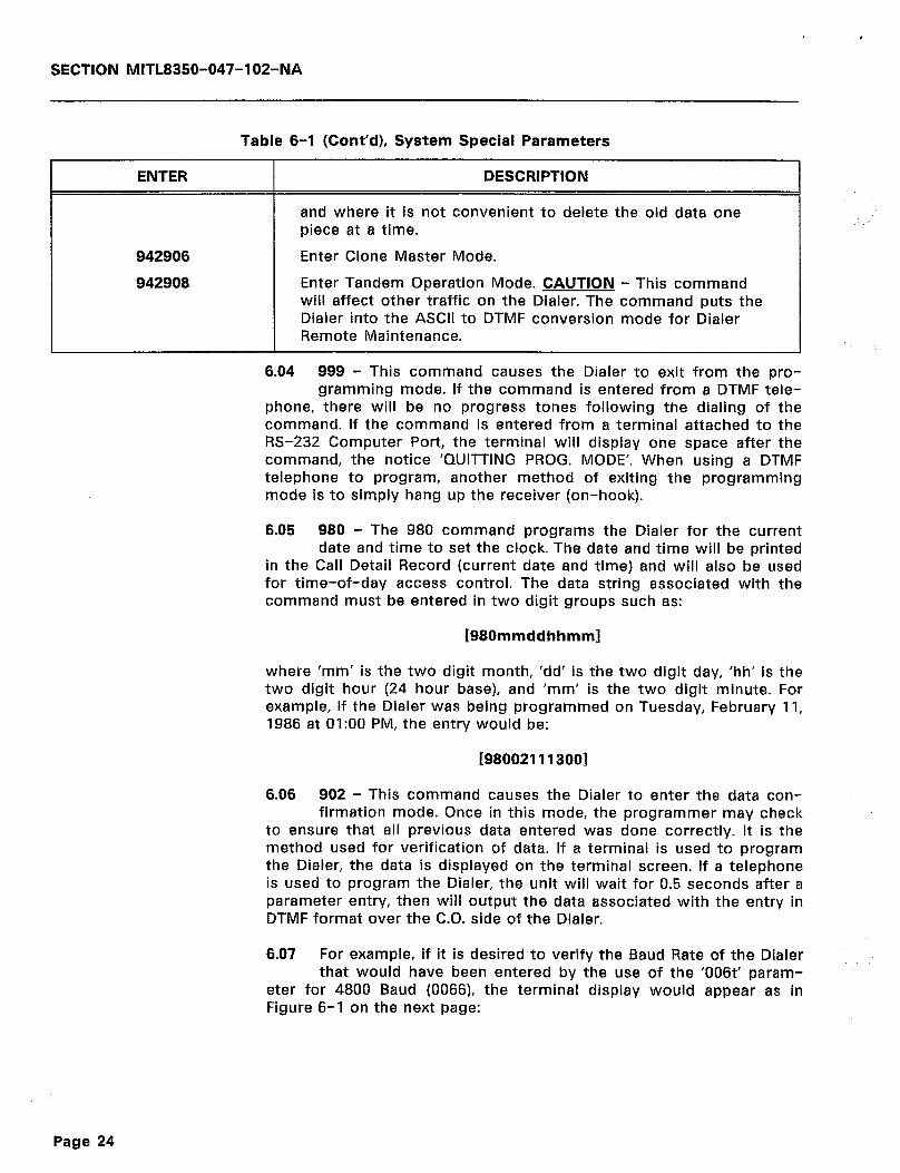
SECTION MITL8350-047-102-NA
Table 6-l (Cont’d), System Special Parameters
ENTER
942906
942908
DESCRIPTION
and where it is not convenient to delete the old data one piece at a time.
Enter Clone Master Mode.
Enter Tandem Operation Mode. CAUTION - This command will affect other traffic on the Dialer. The command puts the Dialer into the ASCII to DTMF conversion mode for Dialer Remote Maintenance.
6.04 999 - This command causes the Dialer to exit from the pro- gramming mode. If the command is entered from a DTMF tele-
phone, there will be no progress tones following the dialing of the command. If the command is entered from a terminal attached to the RS-232 Computer Port, the terminal will display one space after the command, the notice ‘QUITTING PROG. MODE’. When using a DTMF telephone to program, another method of exiting the programming mode is to simply hang up the receiver (on-hook).
6.05 980 - The 980 command programs the Dialer for the current date and time to set the clock. The date and time will be printed
in the Call Detail Record (current date and time) and will also be used for time-of-day access control. The data string associated with the command must be entered in two digit groups such as:
[980mmddhhmml
where ‘mm’ is the two digit month, ‘dd’ is the two digit day, ‘hh’ is the two digit hour (24 hour base), and ‘mm’ is the two digit minute. For example, if the Dialer was being programmed on Tuesday, February 11, 1986 at 01:OO PM, the entry would be:
[980021113001
6.06 902 - This command causes the Dialer to enter the data con- firmation mode. Once in this mode, the programmer may check
to ensure that all previous data entered was done correctly. It is the method used for verification of data. If a terminal is used to program the Dialer, the data is displayed on the terminal screen. If a telephone is used to program the Dialer, the unit will wait for 0.5 seconds after a parameter entry, then will output the data associated with the entry in DTMF format over the C.O. side of the Dialer.
6.07 For example, if it is desired to verify the Baud Rate of the Dialer that would have been entered by the use of the ‘006t’ param-
eter for 4800 Baud (OOSS), the terminal display would appear as in Figure 6-l on the next page:
Page 24
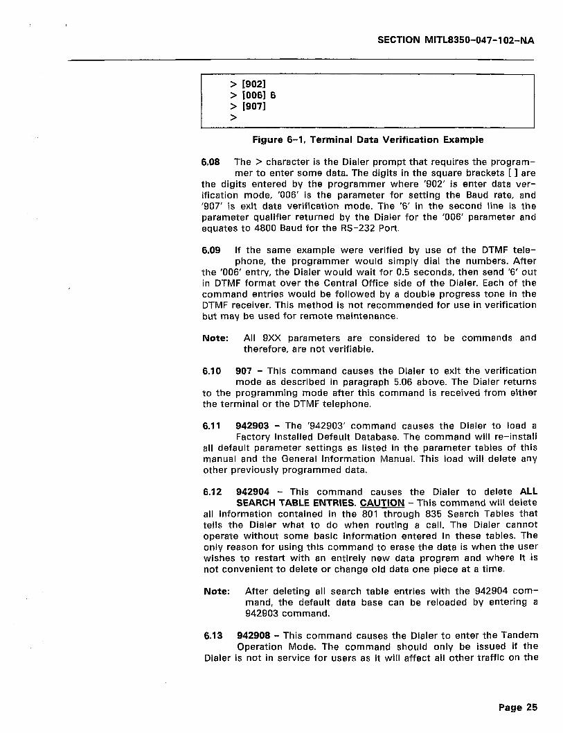
SECTION MITL8350-047-102-NA
> /go21 > [0061 6 > 19071 >
Figure 6-1, Terminal Data Verification Example
6.08 The > character is the Dialer prompt that requires the program- mer to enter some data. The digits in the square brackets [ I are
the digits entered by the programmer where ‘902’ is enter data ver- ification mode, ‘006’ is the parameter for setting the Baud rate, and ‘907’ is exit data verification mode. The ‘6’ in the second line is the parameter qualifier returned by the Dialer for the ‘006’ parameter and equates to 4800 Baud for the RS-232 Port.
6.09 If the same example were verified by use of the DTMF tele- phone, the programmer would simply dial the numbers. After
the ‘006’ entry, the Dialer would wait for 0.5 seconds, then send ‘6’ out in DTMF format over the Central Office side of the Dialer. Each of the command entries would be followed by a double progress tone in the DTMF receiver. This method is not recommended for use in verification but may be used for remote maintenance.
Note: All 9Xx parameters are considered to be commands and therefore, are not verifiable.
6.10 907 - This command causes the Dialer to exit the verificatian mode as described in paragraph 5.06 above. The Dialer returns programming mode after this command is received from either to the
the terminal or the DTMF telephone.
6.11 942903 - The ‘942903’ command causes the Dialer to load a Factory installed Default Database. The command will re-install
all default parameter settings as listed in the parameter tables of this manual and the General Information Manual. This load will delete any other previously programmed data.
6.12 942904 - This command causes the Dialer to delete ALL SEARCH TABLE ENTRIES. CAUTION - This command will delete
all information contained in the 801 through 835 Search Tables that tells the Dialer what to do when routing a call. The Dialer cannot operate without some basic information entered in these tables. The only reason for using this command to erase the data is when the user wishes to restart with an entirely new data program and where it is not convenient to delete or change old data one piece at a time.
Note:
6.13
After deleting all search table entries with the 942904 com- mand, the default data base can be reloaded by entering a 942903 command.
942908 - This command causes the Dialer to enter the Tandem Operation Mode. The command should only be issued if the
Dialer is not in service for users as it will affect all other traffic on the
Page 25
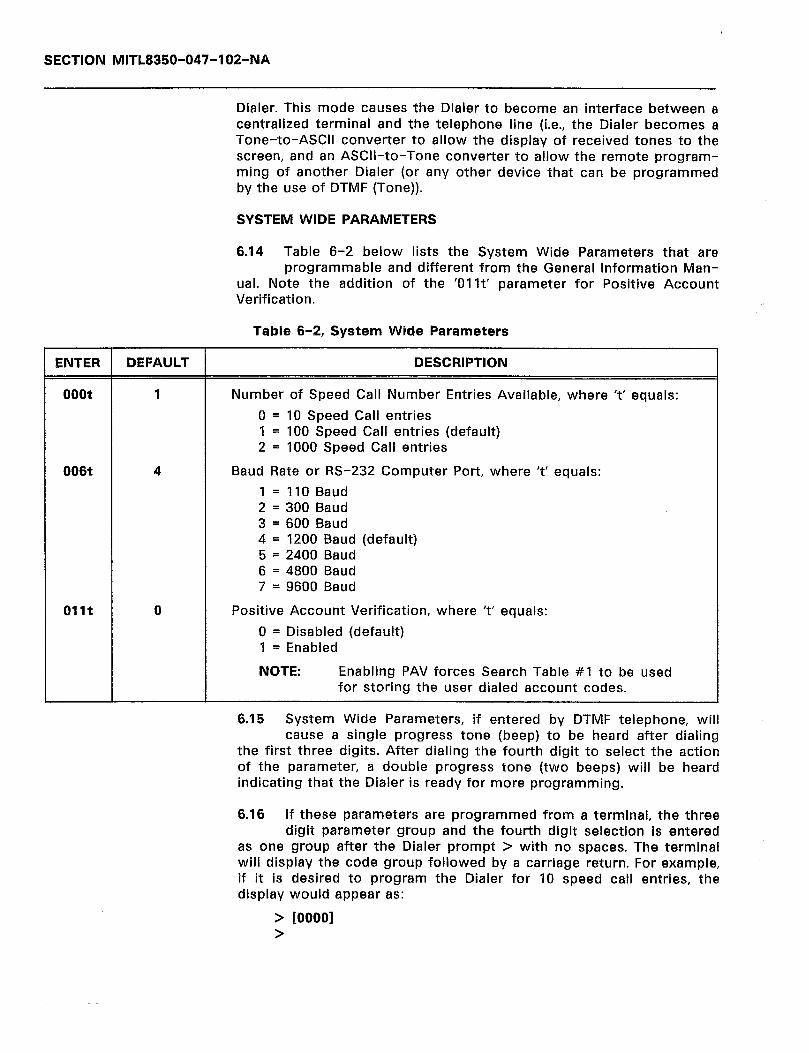
SECTION MITL8350-047-102-NA
Dialer. This mode causes the Dialer to become an interface between a centralized terminal and the telephone line (i.e., the Dialer becomes a Tone-to-ASCII converter to allow the display of received tones to the screen, and an ASCII-to-Tone converter to allow the remote program- ming of another Dialer (or any other device that can be programmed by the use of DTMF (Tone)).
SYSTEM WIDE PARAMETERS
6.14 Table 6-2 below lists the System Wide Parameters that are programmable and different from the General information Man-
ual. Note the addition of the ‘01 It’ parameter for Positive Account Verification.
Table 6-2, System Wide Parameters
ENTER DEFAULT DESCRIPTION
ooot 1
006t 4
Number of Speed Call Number Entries Available, where ‘t’ equals:
0 = 10 Speed Call entries 1 = 100 Speed Call entries (default) 2 = 1000 Speed Call entries
Baud Rate or RS-232 Computer Port, where ‘t’ equals:
1 = 110 Baud 2 = 300 Baud 3 = 600 Baud 4 = 1200 Baud (default) 5 = 2400 Baud 6 = 4800 Baud 7 = 9600 Baud
011t 0 Positive Account Verification, where ‘t’ equals:
0 = Disabled (default) 1 = Enabled
NOTE: Enabling PAV forces Search Table #l to be used for storing the user dialed account codes.
1
6.15 System Wide Parameters, if entered by DTMF telephone, will cause a single progress tone (beep) to be heard after dialing
the first three digits. After dialing the fourth digit to select the action of the parameter, a double progress tone (two beeps) will be heard indicating that the Dialer is ready for more programming.
6.16 If these parameters are programmed from a terminal, the three digit parameter group and the fourth digit selection is entered
as one group after the Dialer prompt > with no spaces. The terminal will display the code group followed by a carriage return. For example, if it is desired to program the Dialer for 10 speed call entries, the display would appear as:
> [00001 >

SECTION MITL8350-047-102-NA
where the brackets [ 1 enclose the parameter digits to be entered on the terminal keyboard by the user. The brackets will not be displayed on the screen.
6.17 OOOt - This parameter tells the Dialer the number of entries to be entered in the Speed Call tables (7nnn). Any number of
speed calls up to the maximum selected number may be entered after programming this parameter. For the method of programming Speed Calls, refer to paragraph 6.43 of this part. The only allowable selections for this command is 10, 100, or 1000 speed call entries. 100 entries is the default that will be loaded if a factory default load command is issued.
6.18 006t - This parameter selects the Baud rate that the RS-232 Computer Port will use in communications to either a terminal
or a CDR unit. The default rate is 1200 Baud and is loaded at unit initialization. The parameter will only take effect after exiting the pro- gramming mode. Selection of rates from 110 to 9600 Baud may be made in seven steps.
6.19 Ollt - This parameters enables or disables the Positive Ac- count Verification feature of the Dialer. The default selection is
‘disabled’. When disabled, the unit functions as a standard SMarT-I’” Dialer without PAV (refer to the General Information Manual for more information). In the enabled state, the Dialer forces Search Table #l to be used for the storage of user dialed Account Codes for verification. With the PAV enabled, note that the r54t and r74t Route Related parameters have different meanings from each other.
TRUNK RELATED PARAMETERS
6.20 Table 6-3 below lists the Trunk Related Parameters that are programmable and different from the ‘General Information Man-
ual’.
Table 6-3, Trunk Related Parameters
ENTER DEFAULT DESCRIPTION
x04t 1 Flash Allowed Time, where ‘t’ equals:
1 = IOOms
x08t 3 Off-Hook Digit Refusal Time, where ‘t’ equals:
0 = None 5 = 500ms 1 = IOOms 6 = 600ms 2 = 200ms 7 = 700ms 3 = 300ms 8 = 800ms 4 = 400ms 9 = 900ms
(continued)
Page 27
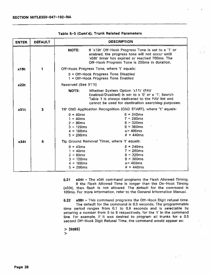
,
SECTION MITL8350-047-102-NA
Table 6-3 (Cont’d), Trunk Related Parameters
ENTER DEFAULT DESCRIPTION
NOTE: If ‘x19t’ Off-Hook Progress Tone is set to a ‘1’ or enabled, the progress tone will not occur until ‘x08t’ timer has expired or reached 700ms. The Off-Hook Progress Tone is 200ms in duration.
x19t
x22t
1 Off-Hook Progress Tone, where ‘t’ equals:
0 = Off-Hook Progress Tone Disabled 1 = Off-Hook Progress Tone Enabled
Reserved (See 01 It)
NOTE: Whether System Option ‘xl It’ (PAV Enabled/Disabled) is set to a ‘0’ or a ‘I’, Search Table 1 is always dedicated to the PAV list and cannot be used for destination searching purposes.
x31t 3
x34t 6
TIP GND Application Recognition (GND START), where “t” equals:
0 = 40ms 6 = 240ms 1 = 40ms 7 = 280ms 2 = 80ms 8 = 320ms 3 = 120ms 9 = 360ms _ 4= 160ms *= 400ms 5 = 200ms # = 440ms
Tip Ground Removal Timer, where ‘t’ equals:
0 = 40ms 6 = 240ms 1 = 40ms 7 = 280ms 2 = 80ms 8 = 320ms 3 = 120ms 9 =,360ms 4 = 160ms *= 400ms 5 = 200ms # = 440ms
6.21 x04t - The x04t command programs the Flash Allowed Timing. If the Flash Allowed Time is longer than the On-Hook Timing
(x03t), then flash is not allowed. The default for the command is IOOms. For more information, refer to the General Information Manual.
6.22 x08t - This command programs the Off-Hook Digit refusal time. The default for the command is 0.3 seconds. The programmable
time period ranges from 0.1 to 0.9 seconds and is selectable by entering a number from 0 to 9 respectively, for the ‘t’ in the command line. For example, if it was desired to program all trunks for a 0.5 second Off-Hook Digit Refusal Time, the command would appear as:
> 150851 >
Page 28

SECTION MITL8350-047-10%NA
on the programming terminal, or when programming with a DTMF telephone, simply dial the ‘5085’ as follows:
1 DIAL 1 HEAR 1 DIAL 1 HEAR 1
where p indicates a single progress tone and hb indicates a progress tone (two beeps) as heard in the telephone receiver.
6.23 x19t - This command programs the Controller to use
double
or not use Off-Hook Progress tone when the user lifts the receiver.
The default for the command is disable Off-Hook Progress tone. For example, if it is desired to program trunk 1 for an Off-Hook Progress tone, the command would appear as shown below:
> Cl1911 >
on the programming terminal, or when programming with a DTMF telephone, simply dial the ‘1191’ as shown below:
j 3’; / HEJR ( “:’ 1 HER- 1
6.24 x34t - The x34t command selects the time period for the Tip Ground Removal Timer. A period within the range of 0 t0 440
ms can be selected by substituting a number from 0 to 9, or x, or # for ‘t’ in the command line when programming with a DTMF telephone. If programming is accomplished from a terminal, the x becomes the letter ‘A’ and the # becomes the letter ‘B’. The default for the command is 240 ms (6). For example, to program all trunks for a 120 ms Tip Ground Removal Time, the command would appear as:
> [53431 >
on the programming terminal, or when programming with a DTMF telephone, simply dial the ‘5343’ as shown below:
DIAL HEAR DIAL HEAR
I 534 I P I 3 I BP I
ROUTE RELATED PARAMETERS
6.25 Tables 6-4 and 6-5 that follow are the Primary Route Param- eters and Alternate Route Parameters respectively, that are pro-
grammable and different from the ‘General Information Manual’.
Page 29

SECTION MITL8350-047-102-NA
Table 6-4, Primary Route Related Parameters
ENTER DEFAULT DESCRIPTION
r51t 0 Route Progress Tones (beeps - p), where ‘t’ equals:
0 = None 3 = b&P I=)
6 = kbbkP& 4 = Mb&
2 = Pb 5 = PPbaP 7 = PbMbPP 8 = &k&h&&b
NOTE: These Route Progress Tones are 100ms in duration with IOOms of silence between them. Route Pro- gress tones will be given to the user before the Dialer cuts the Central Office audio through.
r54t 1 Account Code Type where ‘t’ in System option ‘Ollt’ is set to a ‘0’ or disabled. ‘t’ equal to 0 through 5 apply to using initial account code, while ‘t’ equal to 6 through # apply to using new account code, where ‘t’ equals:
Initial Acct. Code New Acct. Code
0 = Flexible, wait for timeout, 6 = Flexible, wait for timeout, then continue. then continue. 1 = No Account Code. 7 = No Account Code. 2 = Fixed length, wait for 8 = Fixed length, wait for timeout, then reorder. timeout, then reorder. 3 = Fixed length, wait for 9 = Fixed length, wait for timeout, then enter ‘dummy timeout, then enter ‘dummy account code’. account code’. 4 = Same as ‘2’ plus 10 x = Same as ‘8’ plus IO more digits. more digits. 5 = Same as ‘3’ plus 10 # = Same as ‘9’ plus IO more digits. more digits.
PAV Code Type, where ‘t’ in System option ‘01 It’ (PAV) is set to a ‘1’ or enabled, and where ‘t’ equals:
Use Initial Account Code
I= No Account Code. 2= Fixed length of one to nine digits. Send all gathered
digits to Search Table 1. 4= Same as ‘2’ with the fixed length being from 10 to
15 digits.
Use New Account Code
8= Fixed length of one to nine digits. Send all gathered digits to Search Table 1.
*= Same as ‘8’ with the fixed length being 10 to 15 digits.
NOTE: Flexible Account Codes and Dummy Account Codes are not supported when PAV is enabled.
(continued)
Page 30
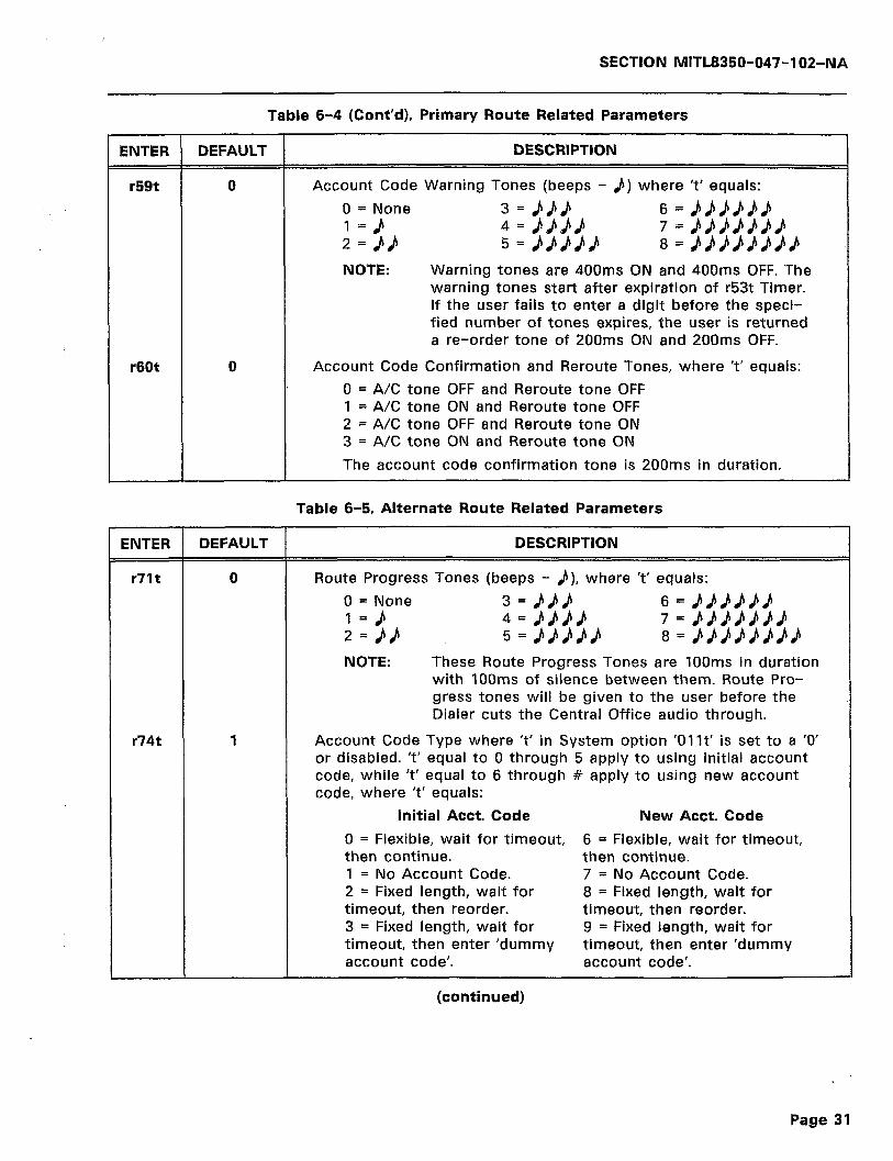
SECTION MITL8350-047-102-NA
Table 6-4 (Cont’d), Primary Route Related Parameters
ENTER DEFAULT DESCRIPTION
r59t 0 Account Code Warning Tones (beeps - b) where ‘t’ equals:
0 = None 3 = bJJd 6 = bbdP)t) l=b 4 = 8b6U 7 = P&#UPPd 2 = 6/, 5 = bBPbb 6 = bb#Ub/ld#h
NOTE: Warning tones are 400ms ON and 400ms OFF. The warning tones start after expiration of r53t Timer. If the user fails to enter a digit before the speci- fied number of tones expires, the user is returned a re-order tone of 200ms ON and 200ms OFF.
r60t 0 Account Code Confirmation and Reroute Tones, where ‘t’ equals:
0 = A/C tone OFF and Reroute tone OFF 1 = A/C tone ON and Reroute tone OFF 2 = A/C tone OFF and Reroute tone ON 3 = A/C tone ON and Reroute tone ON
The account code confirmation tone is 200ms in duration.
Table 6-5, Alternate Route Related Parameters
ENTER DEFAULT DESCRIPTION
r71t 0 Route Progress Tones (beeps - p), where ‘t’ equals:
0 = None 3 = MB 6 = bk&&k/, 1=&I 4 = bPPP 7 = JLUbbPb 2 = bP 5 = BMd/i 8 = bb#UbbLV
NOTE: These Route Progress Tones are 100ms in duration with IOOms of silence between them. Route Pro- gress tones will be given to the user before the Dialer cuts the Central Office audio through.
r74t 1 Account Code Type where ‘t’ in System option ‘01 It’ is set to a ‘0’ or disabled. ‘t’ equal to 0 through 5 apply to using initial account code, while ‘t’ equal to 6 through # apply to using new account code, where ‘t’ equals:
Initial Acct. Code New Acct. Code
0 = Flexible, wait for timeout, 6 = Flexible, wait for timeout, then continue. then continue. 1 = No Account Code. 7 = No Account Code. 2 = Fixed length, wait for 8 = Fixed length, wait for timeout, then reorder. timeout, then reorder. 3 = Fixed length, wait for 9 = Fixed length, wait for timeout, then enter ‘dummy timeout, then enter ‘dummy account code’. account code’.
(continued)
Page 31

SECTION MITL8350-047-102-NA
Table 6-5 (Cont’d), Alternate Route Related Parameters
ENTER DEFAULT DESCRIPTION
Initial Acct. Code New Acct. Code
4 = Same as ‘2’ plus 10 * = Same as ‘8’ plus 10 more digits. more digits. 5 = Same as ‘3’ plus 10 # = Same as ‘9’ plus 10 more digits. more digits.
PAV Code Type, where ‘t’ in System option ‘01 It’ (PAV) is set to a ‘1’ or enabled, and where ‘t’ equals:
Use Initial Account Code
I= No Account Code. 2= Fixed length of one to nine digits. Send all gathered
digits to Search Table 1. 4= Same as ‘2’ with the fixed length being from 10 to
15 digits.
Use New Account Code
8= Fixed length of one to nine digits. Send all gathered digits to Search Table 1.
X= Same as ‘8’ with the fixed length being 10 to 15 digits.
NOTE: Flexible Account Codes and Dummy Account Codes are not supported when PAV is enabled.
r79t 0 Account Code Warning Tones (beeps - &) where ‘t’ equals:
0 = None 3 = d&d 6 = &bdPb& 1 =b 4 = bbbP 7 = #kLLLU 2 = 0U 5=bbPP/i 8 = /I,kk%h/l
NOTE: Warning tones are 400ms ON and 400ms OFF. The warning tones start after expiration of r73t Timer. If the user fails to enter a digit before the speci- fied number of tones expires, the user is returned a re-order tone of 200ms ON and 200ms OFF.
r80t 0 Account Code Confirmation and Reroute Tones, where ‘t’ equals:
0 = A/C tone OFF and Reroute tone OFF 1 = A/C tone ON and Reroute tone OFF 2 = A/C tone OFF and Reroute tone ON 3 = A/C tone ON and Reroute tone ON
The account code confirmation tone is 200ms in duration.
6.26 Since the descriptions for the Primary and Alternate Routes are similar, no differentiation will be made in the paragraphs that
follow. The descriptions will apply to both Tables 6-4 and 6-5 equally, unless otherwise noted.
6.27 r51t, r71 t - These parameters select the Route Progress Tones. These tones will be 100 ms long with a 100 ms silence period
Page 32

,
SECTION MITL8350-047-102-NA
between tones. The tones will be present in the telephone receiver before the Dialer cuts the Central Office audio through. The default selection for ail eight routes is ‘0’ or no progress tones. A maximum of eight tones can be selected by entering a number from 1 to 8 for ‘t’. ‘r’ is a number from 1 to 4 to select the route for the tones. For example, if it is desired to program Route 2 for four progress tones by use of a terminal, the command would be entered as:
> 3514 >
When using a DTMF telephone to program, simply dial ‘3514’ as illus- trated below:
Note: Reroute tones are used in conjunction with registers r51t and r71t (routing tones). If r51t and r71t are set to ‘0’, there will be no reroute tones if the call changes routes.
6.28 r54t, r74t - This parameter selects the Account Code Type when Positive Account Verification (01 It) parameter is disabled.
The default selection for this parameter is ‘1’ or no account code. The only time that the type of account code would come into prominence with PAV disabled, would be if the Controller changes routes or de- faults to another route on call failure. The controller, depending upon the account code type selected would then either use the ‘initial account code’ or request a ‘new account’. In this case, no account code verification would be performed. If ‘01 It’ is enabled, depending on programming, verification will be performed. For example, if it is desired to program Route 3 for an initial account code of fixed length, wait for timeout, then reorder, with PAV disabled, programming from a terminal would appear as:
> [01101 > 145121 >
When a DTMF telephone is used to program the same example, simply dial the ‘0110’ and ‘4512’ as shown below:
6.29 r59t, r79t - This parameter selects the use of Account Code Warning Tones. These tones start after the end of the Account
Code Wait Timer period (i.e., the amount of time that a user has to enter an account code, r53t, r73t). Once the tones have started, the user has to enter a digit before the specified number of tones have
Page 33
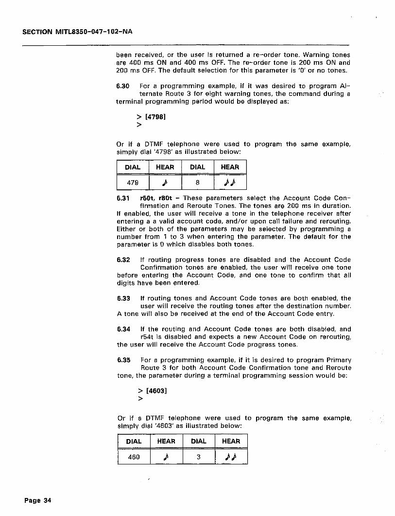
SECTION MITL8350-047-102-NA
been received, or the user is returned a re-order tone. Warning tones are 400 ms ON and 400 ms OFF. The re-order tone is 200 ms ON and 200 ms OFF. The default selection for this parameter is ‘0’ or no tones.
6.30 For a programming example, if it was desired to program Al- ternate Route 3 for eight warning tones, the command during a
terminal programming period would be displayed as:
> [47981 >
Or if a DTMF telephone were used to program the same example, simply dial ‘4798’ as illustrated below:
1 DIAL 1 HEAR 1 DIAL 1 HEAR
6.31 r60t, r80t - These parameters select the Account Code Con- firmation and Reroute Tones. The tones are 200 ms in duration.
If enabled, the user will receive a tone in the telephone receiver after entering a a valid account code, and/or upon call failure and rerouting. Either or both of the parameters may be selected by programming a number from 1 to 3 when entering the parameter. The default for the parameter is 0 which disables both tones.
6.32 If routing progress tones are disabled and the Account Code Confirmation tones are enabled, the user will receive one tone
before entering the Account Code, and one tone to confirm that all digits have been entered.
6.33 If routing tones and Account Code tones are both enabled, the user will receive the routing tones after the destination number.
A tone will also be received at the end of the Account Code entry.
6.34 If the routing and Account Code tones are both disabled, and r54t is disabled and expects a new Account Code on rerouting,
the user will receive the Account Code progress tones.
6.35 For a programming example, if it is desired to program Primary Route 3 for both Account Code Confirmation tone and Reroute
tone, the parameter during a terminal programming session would be:
> 146031 >
Or if a DTMF telephone were used to program the same example, simply dial ‘4603’ as illustrated below:
Page 34
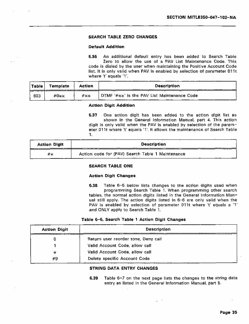
SECTION MITL8350-047-102-NA
SEARCH TABLE ZERO CHANGES
Default Addition
6.36 An additional default entry has been added to Search Table Zero to allow the use of a PAV List Maintenance Code. This
code is dialed by the user when maintaining the Positive Account Code list. It is only valid when PAV is enabled by selection of parameter 01 It where ‘t’ equals ‘1’.
Table Template Action Description
803 #OH WX DTMF ‘#K+’ is the PAV List Maintenance Code
Action Digit Addition
6.37 One action digit has been added to the action digit list as shown in the General Information Manual, part 4. This action
digit is only valid when the PAV is enabled by selection of the param- eter 01 It where ‘t’ equals ‘1’. It allows the maintenance of Search Table 1.
Action Digit
#*
Description
Action code for (PAV) Search Table 1 Maintenance
SEARCH TABLE ONE
Action Digit Changes
6.38 Table 6-6 below lists changes to the action digits used when programming Search Table 1. When programming other search
tables, the normal action digits listed in the General Information Man- ual still apply. The action digits listed in 6-6 are only valid when the PAV is enabled by selection of parameter 01 It where ‘t’ equals a ‘1’ and ONLY apply to Search Table 1.
Action Digit
0
1
*
#9
Table 6-6, Search Table 1 Action Digit Changes
Description
Return user reorder tone, Deny call
Valid Account Code, allow call
Valid Account Code, allow call
Delete specific Account Code
STRING DATA ENTRY CHANGES
6.39 Table 6-7 on the next page lists the changes to the string data entry as listed in the General Information Manual, part 5.
Page 35
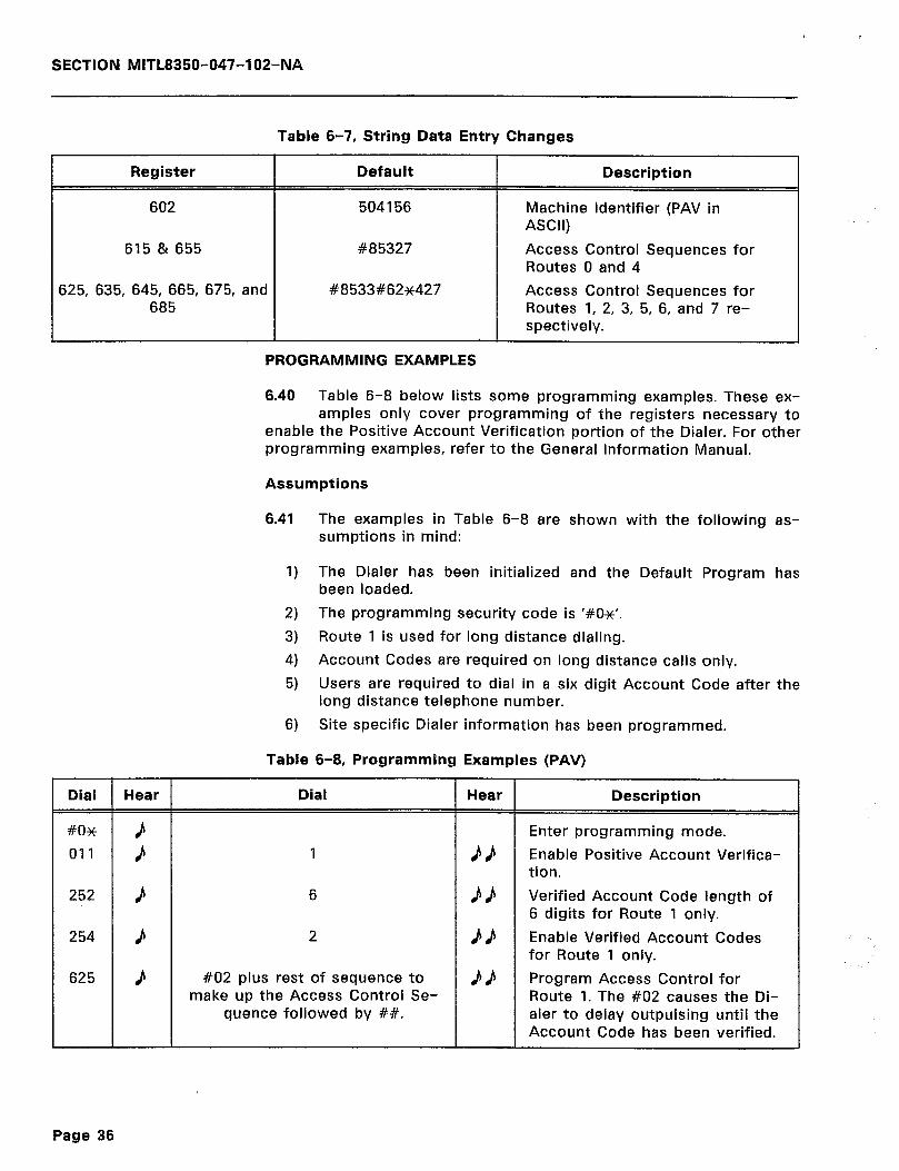
Table 6-7, String Data Entry Changes
SECTION MITL8350-047-102-NA
Register I Default Description
602 504156
615 & 655 #a5327
625, 635, 645, 665, 675, and #8533#62*427 685
Dial r Hear
252
254
625
Machine Identifier (PAV in ASCII)
Access Control Sequences for Routes 0 and 4
Access Control Sequences for Routes 1, 2, 3, 5, 6, and 7 re- spectively.
PROGRAMMING EXAMPLES
6.40 Table 6-6 below lists some programming examples. These ex- amples only cover programming of the registers necessary to
enable the Positive Account Verification portion of the Dialer. For other programming examples, refer to the General Information Manual.
Assumptions
6.41 The examples in Table 6-6 are shown with the following as- sumptions in mind:
1)
2)
3)
4)
5)
6)
The Dialer has been initialized and the Default Program has been loaded.
The programming security code is ‘#OX’.
Route 1 is used for long distance dialing.
Account Codes are required on long distance calls only.
Users are required to dial in a six digit Account Code after the long distance telephone number.
Site specific Dialer information has been programmed.
Table 6-8, Programming Examples (PAV)
Dial Hear Description
1
6
2
#02 plus rest of sequence make up the Access Control
quence followed by ##.
to Se-
Enter programming mode.
Enable Positive Account Verifica- tion.
Verified Account Code length of 6 digits for Route 1 only.
Enable Verified Account Codes for Route 1 only.
Program Access Control for Route 1. The #02 causes the Di- aler to delay outpulsing until the Account Code has been verified.
Page 36
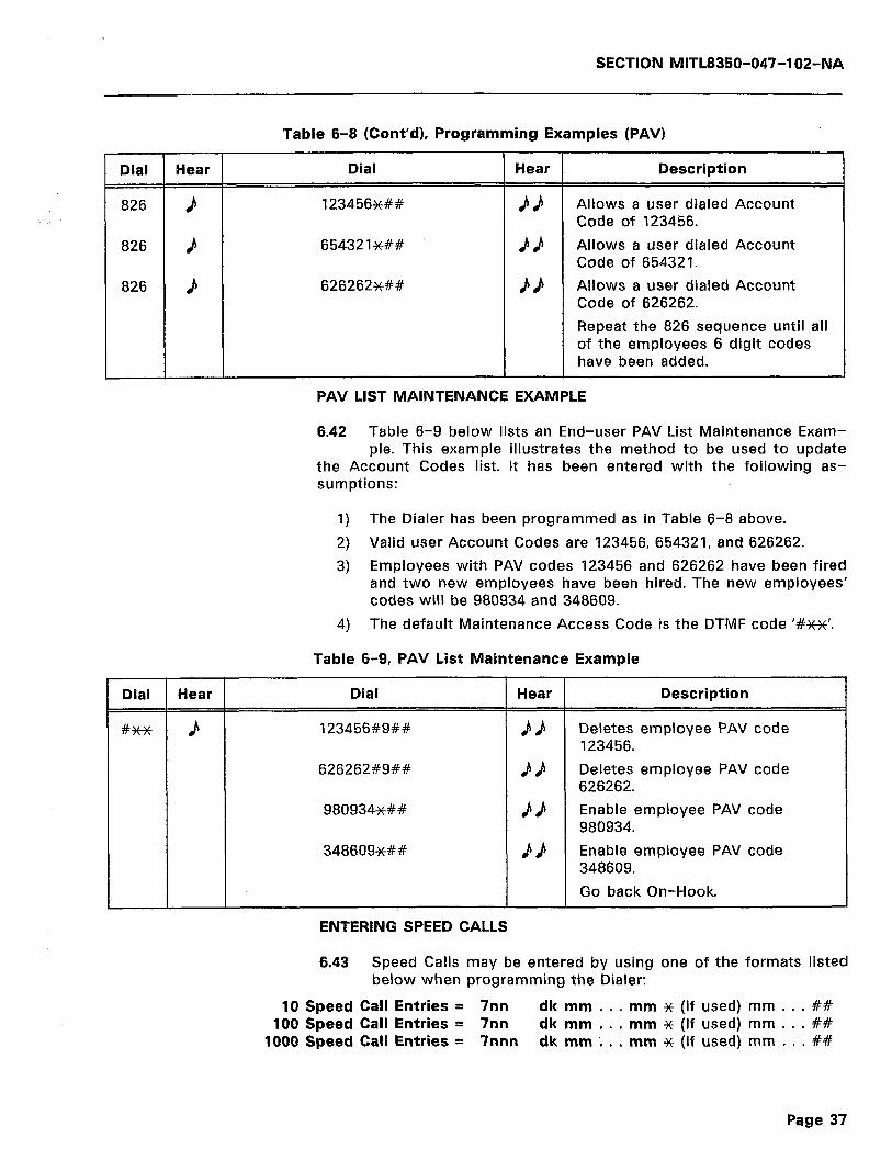
SECTION MITL8350-047-102-NA
Table 6-8 (Cont’d), Programming Examples (PAV)
Dial
826
826
826
Dial
L
Hear _
P
J
b
Hear
P
Dial
123456&k&
654321##
626262##
Hear Description
Allows a user dialed Account Code of 123456.
Allows a user dialed Account Code of 654321.
Allows a user dialed Account Code of 626262.
Repeat the 826 sequence until all of the employees 6 digit codes have been added.
PAV LIST MAINTENANCE EXAMPLE
6.42 Table 6-9 below lists an End-user PAV List Maintenance Exam- ple. This example illustrates the method to be used to update
the Account Codes list. It has been entered with the following as- sumptions:
1) The Dialer has been programmed as in Table 6-8 above.
2) Valid user Account Codes are 123456, 654321, and 626262.
3) Employees with PAV codes 123456 and 626262 have been fired and two new employees have been hired. The new employees’ codes will be 980934 and 348609.
4) The default Maintenance Access Code is the DTMF code ‘#w’.
Table 6-9, PAV List Maintenance Example
Dial
123456#9##
626262#9##
980934x+Y#
348609*##
Hear
#u bb
P/i
PP
ENTERING SPEED CALLS
Description
Deletes employee PAV code 123456.
Deletes employee PAV code 626262.
Enable employee PAV code 980934.
Enable employee PAV code 348609.
Go back On-Hook.
6.43 Speed Calls may be entered by using one of the formats listed below when programming the Dialer:
10 Speed Call Entries = 7nn dk mm . . . mm x (if used) mm . . . ## 100 Speed Call Entries = 7nn dk mm . . . mm * (if used) mm . . . ##
1000 Speed Call Entries = 7nnn dk mm ‘. . . mm x (if used) mm . . . ##
Page 37

SECTION MITL8350-047-102-NA
6.44 Table 6-10 below lists the digits required for Speed Call entries where ‘n’ is the number or location (bin) of the Speed Call
Number. If 10 Speed Call entries are used, ‘nn’ is 00 through 09. If 100 Speed Call entries are used, ‘nn’ is 00 through 99. If 1000 Speed Call entries are used, ‘nnn’ is 000 through 999. ‘d’ is the key used to determine the trunk(s) that have access to the particular Speed Call Number. ‘k’ is the Network Override Key that is used to select the allowed routing for the particular Speed Call Number. ‘mm . . . mm’ is the telephone number to be dialed. ‘*’ is the delimiter used to tell the Dialer that if any other digits are entered, they will be considered Account Code Digits as illustrated by the ‘p’ entries. ‘##’ is the Speed Call number entry terminator and will cause the number to be entered into the Dialer memory.
Table 6-10, Speed Call Entries
FIRST DIGIT = 7 SPEED CALL
DIAL DEFINITION
7nndkmm...mm## or
7nndkmm...mmxpp...pp##
Format for IO Speed Call entries where: nn is the number of the Speed Call entry (00 - 09).
7nndkmm...mm## or
7nndkmm...mmxpp...pp##
Format for 100 Speed Call entries where: nn is the number of the Speed Call entry (00 - 99).
-/nnndkmm...mm## or
7nnndkmm...mmxpp...pp##
Format for 1000 Speed Call entries where: nnn is the number of the Speed Call entry (000 - 999).
d is the key that selects the trunks to access the call number as follows:
DIGIT ALLOWED TRUNKS
0 ALL 1 TRUNK 1 2 TRUNK 2 3 TRUNKS I,2 4 TRUNK 3 5 TRUNKS I,3 6 TRUNKS 2,3 7 TRUNKS 1,2,3 8 TRUNK 4 9 TRUNKS I,4 * TRUNKS 2,4 # TRUNKS ‘I ,2,4 C TRUNKS 3,4 D TRUNKS 1,3,4 E TRUNKS 2,3,4
NOTE: The C, D, and E entries above may be made from a terminal.
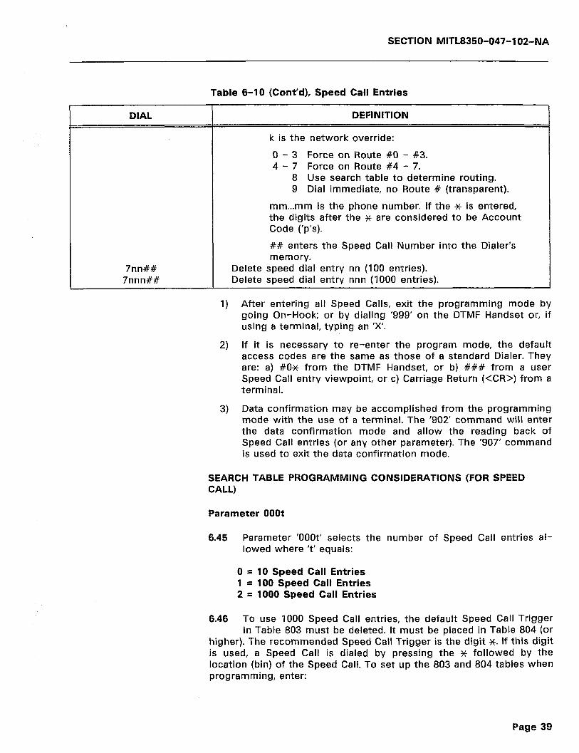
SECTION MITL8350-047-102-NA
Table 6-10 (Cont’d), Speed Call Entries
DIAL DEFINITION
k is the network override:
0 - 3 Force on Route #O - #3. 4 - 7 Force on Route #4 - 7.
8 Use search table to determine routing. 9 Dial immediate, no Route # (transparent).
mm...mm is the phone number. If the % is entered, the digits after the * are considered to be Account Code (‘p’s).
## enters the Speed Call Number into the Dialer’s memory.
7nn## 7nnn## I
Delete speed dial entry nn (100 entries). Delete speed dial entry nnn (1000 entries).
1) After entering all Speed Calls, exit the programming mode by going On-Hook; or by dialing ‘999’ on the DTMF Handset or, if using a terminal, typing an ‘X’.
2) If it is necessary to re-enter the program mode, the default access codes are the same as those of a standard Dialer. They are: a) #Ox from the DTMF Handset, or b) ### from a user Speed Call entry viewpoint, or c) Carriage Return (<CR>) from a terminal.
3) Data confirmation may be accomplished from the programming mode with the use of a terminal. The ‘902’ command will enter the data confirmation mode and allow the reading back of Speed Call entries (or any other parameter). The ‘907’ command is used to exit the data confirmation mode.
SEARCH TABLE PROGRAMMING CONSIDERATIONS (FOR SPEED CALL)
Parameter OOOt
6.45 Parameter ‘OOOt’ selects the number of Speed Call entries al- lowed where ‘t’ equals:
0 = 10 Speed Call Entries 1 = 100 Speed Call Entries 2 = 1000 Speed Call Entries
6.46 To use 1000 Speed Call entries, the default Speed Call Trigger in Table 803 must be deleted. It must be placed in Table 804 (or
higher). The recommended Speed Call Trigger is the digit K. If this digit is used, a Speed Call is dialed by pressing the * followed by the location (bin) of the Speed Call. To set up the 803 and 804 tables when programming, enter:
Page 39

SECTION MITL8350-047-102-NA
803 *#9#9#9## Deletes defaulted *nn
804 *#9#9#9#2## Programs Xnnn into Dialer
6.47 If ‘OOOt’ is set to ‘0’, the programming slot number is still two digits. This must be within the range of 00 through 09. A single
digit Speed Call Trigger (i.e., 802 H9#2) is possible for the Search Tables, but must be programmed within the range of 700 through 709 in the Speed Call slots.
.. . .
. . .’
6.48 The maximum length of the Speed Call field is 30 characters (29 digits and a XC). The maximum length of a Speed Call or an
Account Code field alone within the 30 character limit is 23 digits.
Page 40
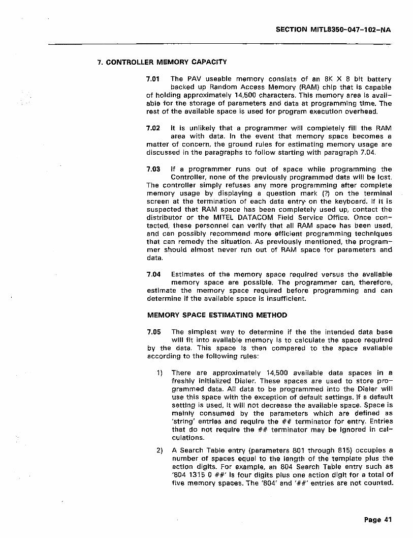
SECTION MITL8350-047-102-NA
7. CONTROLLER MEMORY CAPACITY
7.01 The PAV useable memory consists of an 8K X 8 bit battery backed up Random Access Memory (RAM) chip that is capable
of holding approximately 14,500 characters. This memory area is avail- able for the storage of parameters and data at programming time. The rest of the available space is used for program execution overhead.
7.02 It is unlikely that a programmer will completely fill the RAM area with data. In the event that memory space becomes a
matter of concern, the ground rules for estimating memory usage are discussed in the paragraphs to follow starting with paragraph 7.04.
7.03 If a programmer runs out of space while programming the Controller, none of the previously programmed data will be lost.
The controller simply refuses any more programming after complete memory usage by displaying a question mark (?) on the terminal screen at the termination of each data entry on the keyboard. If it is suspected that RAM space has been completely used up, contact the distributor or the MITEL DATACOM Field Service Office. Once con- tacted, these personnel can verify that all RAM space has been used, and can possibly recommend more efficient programming techniques that can remedy the situation. As previously mentioned, the program- mer should almost never run out of RAM space for parameters and data.
7.04 Estimates of the memory space required versus the available memory space are possible. The programmer can, therefore,
estimate the memory space required before programming and can determine if the available space is insufficient.
MEMORY SPACE ESTIMATING METHOD
7.05 The simplest way to determine if the the intended data base will fit into available memory is to calculate the space required
by the data. This space is then compared to the space available according to the following rules:
1) There are approximately 14,500 available data spaces in a freshly initialized Dialer. These spaces are used to store pro- grammed data. All data to be programmed into the Dialer will use this space with the exception of default settings. If a default setting is used, it will not decrease the available space. Space is mainly consumed by the parameters which are defined as ‘string’ entries and require the ## terminator for entry. Entries that do not require the ## terminator may be ignored in cal- culations.
2) A Search Table entry (parameters 801 through 815) occupies a number of spaces equal to the length of the template plus the action digits. For example, an 804 Search Table entry such as ‘804 1315 0 ##’ is four digits plus one action digit for a total of five memory spaces. The ‘804’ and ‘##’ entries are not counted.
Page 41

SECTION MITL8350-047-102-NA
3)
4)
5)
Note:
7.06
An entry of ‘803 #9#9#9#2’ is six digits plus two action digits for a total of eight memory spaces.
An Account Code entry (parameters 821 through 835) occupies the number of spaces equal to the length of the template (account code) plus the action digits. The account code ‘12345’ with an action of ‘valid account code, allow call’ would be programmed as ‘825 12345 ##’ and would require six spaces. The ‘825’ and ‘##’ entries are not counted.
A Speed Call entry occupies a number of spaces equal to the length of the Speed Call plus six (an internal Controller require- ment) spaces. This number must be rounded off to the next larger even number if the result is odd. For example, a Speed Call programmed as ‘7nnn 8 139311212 ##’ requires 14 spaces in memory. The eight digits of the telephone number plus six additional for the Controller equals 14. The ‘7nnn’ and ‘##’ entries are not counted.
Access Control strings, OCC Access Numbers, OCC Authoriza- tion Codes, etc., all count, but in general require so little space that they may be neglected for the purpose of space estima- tions.
Deleting a Speed Call with the ‘7nnn##’ command does not reclaim all memory previously occupied by that entry. After deletion, the memory space increase only by the number of digits in the removed speed call number and not by the ‘+ 6’ factor that was added in the calculation in 4) above.
Figures 7-l through 7-3 are calculation worksheets that have been included to assist in memory space calculations. Figure
7-l is to be used in calculating Search Table space. Figure 7-2 is to be used in calculating Account Code space, and Figure 7-3 is to be used in calculating Speed Call number space. These figures are located at the end of this part.
7.07 The sum of the Search Tables + Account Codes + Speed Call Numbers must be less than approximately 14,500 spaces. Using
the assumption that there will be one speed call number for each password, and that the 801 through 815 search tables are not required to be programmed (as is the usual case), the following generalizations can be made:
Let X = QUANTITY
ACCT. CODES SPEED CALLS
(Length + 2) X + (Length + 6) X = 14,500
7.08 For example, assume that the unit is programmed with all 5 digit Account Codes and 7 digit Speed Call numbers. Using the
equation under paragraph 7.07 above, the amount of space used would be 725 spaces as shown below:
(5 + 2)X + (7 + 6)X = 14,500
Page 42

SECTION MITL8350-047-102-NA
7x + 13x = 14,500
20x = 14500
14500 x= 20
X = 725
Therefore, 725 five digit account codes and 725 seven digit speed calls numbers may be safely stored in the RAM memory.
7.09 Another example would be to assume that there will be twice as many account codes as speed call numbers. Account codes
are still 5 digits long and speed call numbers are 7 digits long:
(5 + 2)2X + (7 + 6)X = 14,500
(7)2X + 13X = 14,500
14x + 13x = 14500
27X = ‘I4500
14500 x= 27
x = 537
Therefore, 1,074 five digit account codes (2X) and 537 seven digit speed call numbers may safely be stored in the RAM memory.
7.10 If the extreme case were considered and based on the formula above, up to 381 15-digit account codes and 381 l5-digit
speed call numbers could be stored in the RAM memory. For those who demand more detailed calculations, simultaneous solutions using X and Y unknowns would allow calculation of uneven numbers of account code/speed call quantities. Calculus formulae would allow both lengths and quantities to be varied, but for simplicity, it is easier to use the charts included, with known intentions.
Page 43
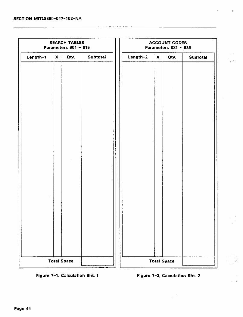
SECTION MITL8350-047-102-NA
SEARCH TABLES Parameters 801 - 815
Length+1 X Qty. Subtotal
Total Space
Figure 7-1, Calculation Sht. 1
Length+2
ACCOUNT CODES Parameters 821 - 835
X Qty.
Total Space
Subtotal
Figure 7-2, Calculation Sht. 2
Page 44
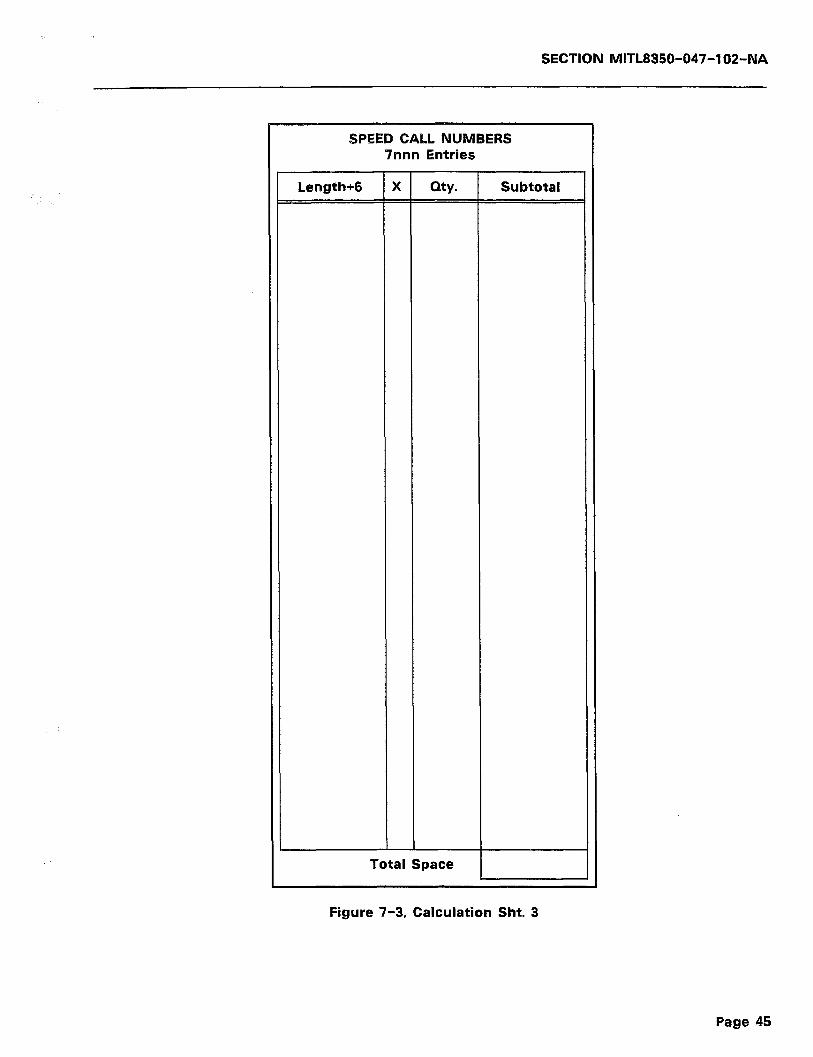
1.
SECTION MITL8350-047-102-NA
SPEED CALL NUMBERS 7nnn Entries
Length+6 X my. Subtotal
Total Space
Figure 7-3, Calculation Sht. 3
Page 45
SECTION MITL8350-047-102-NA
--- THIS PAGE INTENTIONALLY LEFT BLANK ---
Page 46

SECTION MITL8350-047-102-NA
8. TECHNICAL CIRCUIT DESCRIPTION
INTRODUCTION
8.01 This part will be added at a later date. For the present, refer to Appendix C, Figures C-l and C-Z of the General Information
Manual for an overall block diagram, and a simplified electrical diagram of the Controller, respectively.
Page 47

SECTION MITL8350-047-102-NA
--- THIS PAGE INTENTIONALLY LEFT BLANK ---
Page 48
SECTION MITL8350-047-1 OZ-NA
9. PHYSICAL MAINTENANCE AND TROUBLESHOOTING
PHYSICAL MAINTENANCE
9.01 The SMarT-1’” PAV, as is evident, is a fully self-contained unit. As such, it has no user repairable parts. If the warranty seal
over the unit fasteners is broken, the warranty is void. In case of failure, replace the Controller as follows:
I) Power down the unit. This will cut-through the subscriber side to the CO side.
2) Remove the RJ31KA31 plug from the Telco supplied socket. The shorting bars in the RJ31XKA31A will cut-through to the line. Then,
3) Replace the Controller and re-connect.
4) Proceed as if a new installation.
TROUBLESHOOTING
9.02 This part will be added at a later date.
Page 49

SECTION MITL8350-047-102-NA
--- THIS PAGE INTENTIONALLY LEFT BLANK ---
Page 50
SECTION MITL8350-047-102-NA
APPENDlX A
FCC INTERCONNECTION REQUIREMENTS
Al.01 This equipment has been approved by the Federal Communica- tions Commission (FCC) as not being harmful to the telephone
network when connected directly to the telephone lines through the standard connection cabling provided with the unit. This section is applicable to telephone interconnection in the United States.
Al.02 Prior to the interconnection of this equipment, the local tele- phone company is to be notified; inform the company that you
have FCC-registered equipment that you wish to connect to their trunks. Give them the following information:
0 The telephone number of the line that will connect to the unit.
0 The equipment being connected is a MITEL DATACOM INC. model SMarT-I’” or SMarT-IA’” with PAV Common Carrier Ac- cess Dialer and Call Controller.
a The FCC Registration Number for the SMarT-I’” units is EMP 85B- 14558-LR-E.
0 The FCC Ringer Equivalence Number (REN) which is 0.7B.
-0 The Connector Jacks required are RJ31X.
CONNECTION LIMITATIONS
Al.03 Due to the FCC Part 68 Rule, no connection can be made to party lines and to coin telephone service. This unit is designed
to be used on standard-device telephone lines. If there are any ques- tions about the telephone line, such as how many pieces of equipment may be connected to it, the telephone company will provide this information upon request.
NETWORK CHANGES
Al.04 The telephone company may make changes to it’s communica- tion service; such changes may include the change of trunk
circuits, changes in the operational characteristics of its trunks, etc. Before doing this, however, the company shall provide official notifica- tion, so that the operation of the Dialer service will not be interrupted.
MAINTENANCE LIMITATIONS
Al.05 This equipment has been registered with the FCC for direct connection to the telephone network. Under the FCC program,
the user is restricted from making any changes or repairs and from performing any maintenance operations other than those specifically included in this document.
Page A--l
SECTION MITL8350-047-102-NA
Al.06 There are no user repairable parts within the unit. It is sealed against user maintenance. If opened, all warranties are voided.
Al.07 No cabling or wiring changes within the unit are permitted by the user. Plug-ended cables, as detailed in this document, are
to be used for all external connections between the unit and the telephone company interface jack.
Al.08 Power supply components and cabling is only to be changed or maintained by MITEL DATACOM INC. or by an authorized agent
of MITEL DATACOM INC.
TROUBLE CORRECTIONS
Al.09 For all malfunctions, appropriate field service is provided by MITEL DATACOM INC. or its authorized agents.
DISCONNECTION
Al.10 If it is ever decided to permanently disconnect the SMarT-I’” Common Carrier Access Dialer and Call Controller with PAV
from the present line, please notify the telephone company of this change.
Page A-2
SECTION MITL8350-047-102-NA
APPENDIX B OVERALL TOPICAL INDEX
CONTENTS PAGE
ACCOUNT CODE CONFIRMATION/REROUTE TONES
SEE ROUTE RELATED PARAMETERS 38 SEETABLE 6-4 ._ _..... __. __ _........_ .__ ._ 35 SEE TABLE 6-5 36
ACCOUNT CODE TVPE SEE ROUTE RELATED PARAMETERS 37 SEETABLE 6-4 .._......... _........._...... 34
SEE TABLE 6-5 35 ACCOUNT CODE VERIFICATION
SEE OPERATING DESCRIPTION 19
ACCOUNT CODE WARNING TONES SEE DIALER DESCRIPTION 4 SEE ROUTE RELATED PARAMETERS 37
SEE TABLE 6-4 35 SEE TABLE 6-5 36
ACCOUNT CODES SEE OIALER DESCRIPTION 4 SEE OPERATING DESCRlmlON 19
ACTION DIGIT ADDITION
SEE SEARCH TABLE ZERO CHANGES 39 ACTION DIGIT CHANGES
SEESEARCH TABLE ONE _. _........... 39
APPENDIX A CONNECTION LIMITATIONS A-l
CONNECTOR JACKS _....... _........ ___. _. _, .,.... A-l
DISCONNECTION A-2 FCC INTERCONNECTION REQUIREMENTS A-l FCC REGISTRATION NUMBER A-l
MAINTENANCE LIMITATIONS A-l NETWORKCHANGES __._.....___.._..___.______._.._ A-l RINGER EQUIVALENCE NUMBER. A-l TROUBLE CORRECTIONS _. _... ___ __. __ ._._ _.... A-2
BATTERY FEED SEE HARDWARE SPECIFICATIONS 5
BAUD RATE
SEE RS-232 PORT SPECIFICATIONS 7 BAUD RATE/RS-232 PORT
SEE SYSTEM WIDE PARAMETERS 31
SEE TABLE 6-2 30 BIT EIGHT SENSE
SEE RS-232 PORT SPECIFICATIONS 7
BITS PER CHARACTER SEE RS-232 PORT SPECIFICATIONS 7
CALCULATION SHEETS SEE CONTROLLER MEMORY CAPACITY 48
SEE FIGURE 7-l 48
SEE FIGURE 7-2 46 SEE FIGURE 7-3 ..____ __ .._ __ 49
CLEAR ALL SEARCH TABLES SEE TABLE 5-2 22
CLEAR SEARCH TABLES
SEE SPECIAL FUNCTIONS 29 SEE TABLE 6-l _. ._ ..__.... _. ._ ._ .._ _., 27
CLONE MASTER MODE
SEE TABLE 5-2 22 CONNECTION LIMITATIONS
SEE APPENDIX A A-l
CONNECTION PROCEDURE SEE CONNECTIONS .._ ..__ _.. __ __ .._ _..... _._ 16
CONNECTIONS
RJ31X USOC JACK AND CABLE 16 RS-232 PORT CONFIGURATION 16 SEE ELECTRICAL/MECHANICAL SPECIFICATIONS 7
SEE UNPACKING, INSTALLATION AND ORDERING INFORMATION. 12
CONNECTOR JACKS SEE APPENDIX A A-l
CONTENTS PAGE
CONTROLLER MEMORV CAPACIN
CALCULATION SHEETS ............................... 48
MEMORY SPACE ESTIMATING METHOD ..................... 45
SEE DETAILED PROGRAMMING .......................... 45
DATA CONFIRMATION
SEE SPEED CALL ENTRY ............................... 21 DATA CONFIRMATION MODE
SEE TABLE 5-2 ..................................... 22
DC BALANCE SEE HARDWARE SPECIFICATIONS .......................... 5
DEFAULT ADDITION
SEE SEARCH TABLE ZERO CHANGES ..................... 39
DEFAULT LISTING SEE OPERATING DESCRIPTION ........................... 22
SEE TABLE 5-3 ..................................... 22 DEFAULT SEARCH TABLE
SEE TABLE 6-3 ..................................... 32
SEE TRUNK RELATED PARAMETERS ....................... 33 DETAILED PROGRAMMING
CONTROLLER MEMORY CAPACITY ....................... 45
ENTERING SPEED CALLS .............................. 41
INTRODUCTION ..................................... 27 PAV LIST MAINTENANCE EXAMPLE ....................... 41
PROGRAMMING EXAMPLES ............................ 40
ROUTE RELATED PARAMETERS .......................... 33
SEARCH TABLE ONE ................................. 39
SEARCH TABLE PROGRAMMING CONSIDERATIONS ............. 43
SEARCH TABLE ZERO CHANGES .......................... 39 SPECIAL FUNCTIONS ............................ .. 27
STRING DATA ENTRY CHANGES ........................ 39
SYSTEM WIDE PARAMETERS ............................ 30 TRUNK RELATED PARAMETERS ........................ 31
DIALER DESCRIPTION SEE GENERAL DESCRIPTION ......................... ... 3
DIALTONE
SEE HARDWARE SPECIFICATIONS ....................... .. 6 DIMENSIONS
SEE ELECTRICAL/MECHANICAL SPECIFICATIONS ................ 7
DISCONNECTION SEE APPENDIX A ................................... A-2
DOCUMENT CONVENTIONS
SEE INTRODUCTION .................................. 2
DOCUMENT HISTORY SEE INTRODUCTION .................................. 2
DOCUMENT NUMBERING SEE INTRODUCTION ................................... 1
DOCUMENT OBJECTIVES
SEE INTRODUCTION ................................... 1
DOCUMENT OVERVIEW SEE INTRODUCTION ................................... 1
DTMF RECEIVER SEE HARDWARE SPECIFICATIONS ....................... 6
DTMF SENDER
SEE HARDWARE SPECIFICATIONS .......................... 6
ELECTRICAL/MECHANICAL SPECIFICATIONS SEE SPECIFICATIONS .................................. 7
SEE TABLE 3-3 ...................................... 7
ENTER DATA CONFIRMATION MODE SEE SPECIAL FUNCTIONS .............................. 28
SEETABLE6-1 ..................................... 27
ENTER DATE AND TIME SEE SPECIAL FUNCTIONS .............................. 28
SEETABLE 6-1 ..................................... 27
ENTER TANDEM MODE SEE TABLE 5-2 ..................................... 22
SEE TABLE 6-l ..................................... 28
ENTERING PROGRAM MODE SEE SPEED CALL ENTRY ............................... 21
Page B-l
SECTION MITL8350-047-102-NA
ENTERING SPEED CALLS
CONTENTS PAGE
SEE DETAILED PROGRAMMING 41
SEE OPERATING DESCRIFTION 20
SPEED CALL FORMAT 20 EXIT DATA CONFIRMATION
SEE SPECIAL FUNCTIONS 29
SEE TABLE 6-l 27 EXIT PROGRAM MODE
SEE SPECIAL FUNCTIONS 28 SEE TABLE 6-l 27
EXIT PROGRAMMING
SEE USER OPERATION 24 MEMORY SPACE ESTIMATING METHOD
CONTROLLER MEMORY CAPACITY 45 MODE OF OPERATION
SEE TABLE 5-2 22 SEE RS-232 PORT SPECIFICATIONS 7
EXITING PROGRAM MODE MOUNTING
SEE SPEED CALL ENTRY 21 SEE ELECTRICAL/MECHANICAL SPECIFICATIONS 7
EXPANDED MEMORY AREA SEE UNPACKING, INSTALLATION AN0 ORDERING INFORMATION. 12
SEE OPERATING DESCRIPTION 19
NETWORK CHANGES
FCC INTERCONNECTION REQUIREMENTS SEE APPENDIX A A-l
GENERAL _. ..__ _. NETWORK OVERRIDE
SEE APPENDIX A A-l SEE TABLE 5-1 20
FCC REGISTRATION NUMBER NEW ACCOUNT CODE
SEE APPENDIX A A-l SEE DIALER DESCRIPTION 4
FCC RINGER EQUIVALENCE NUMBER OF SPEED CALL ENTRIES
SEE HARDWARE SPECIFICATIONS 5 SEE SYSTEM WIDE PARAMETERS 31
FEATURES AND CAPABILTIES SEE TABLE 6-2 30
SEE GENERAL DESCRIPTION 3
FEED RESISTANCE SEE HARDWARE SPECIFICATIONS 5
FLASH ALLOWED TIME
SEE TABLE 6-3 31
SEE TRUNK RELATED PARAMETERS 32
OFF-HOOK CURRENT SEE HARDWARE SPECIFICATIONS
OFF-HOOK DIGIT REFUSAL TIME SEE TABLE 6-3 SEE TRUNK RELATED PARAMETERS
OFF-HOOK PROGRESS TONE SEE TABLE 6-3 SEE TRUNK RELATED PARAMETERS
OPEN CIRCUIT VOLTAGE
SEE HAROWARE SPECIFICATIONS OPERATING CURRENT
5
31 32
GENERAL DESCRIPTION DIALER DESCRIPTION 3 FEATURES AND CAPABILITIES 3
GROUNDING VOLTAGE SEE HARDWARE SPECIFICATIONS 5
HARDWARE SPECIFICATIONS
SEE SPECIFICATIONS SEE TABLE 3-l
HUMIDITY
SEE HARDWARE SPECIFICATIONS
5
5.6
6
INITIALIZING PROCEDURE SEE INITIALIZING THE DIALER 19
INITIALIZING THE DIALER
PROCEDURE .___..................._..........., 19 SEE OPERATING DESCRIFIION 19
INSTALLATION REQUIREMENTS
SEE UNPACKING, INSTALLATION AND ORDERING INFORMATION. 9 INTENDED AUDIENCE
SEE INTRODUCTION __ 2
INTRODUCTION DOCUMENTCONVENTIONS .._.._..._........_....... 2 DOCUMENT HISTORY _.. ___.. 2
DOCUMENT OBJECTIVES 1 DOCUMENT OVERVIEW................................. 1 INTENDED AUDIENCE ____.....__,.._.........., 2
READER COMMENTS __...... .._ _...... 2
JACKS SEE APPENDIX A A-l
KEYSLOT MOUNTING SEE MOUNTING 12
LEAKAGE
SEE HARDWARE SPECIFICATIONS 5 LOAD DEFAULT DATABASE
SEE SPECIAL FUNCTIONS 29
CONTENTS PAGE
SEE TABLE 5-2 22 SEE TABLE 6-1 27
MAINTENANCE LIMITATIONS SEE APPENDIX A A-l
MAKING TELEPHONE CALLS
32 33
5
SEE HARDWARE SPECIFICATIONS 5 OPERATING DESCRIPTION
DEFAULT LISTING ................................... 22
ENTERING SPEED CALLS ............................... 20 GENERAL ......................................... 19 INITIALIZING THE DIALER .............................. 19
.................... 22
.................... 24 SPECIFIC DEFAULTS USER OPERATION
OPERATING RANGE
SEE HARDWARE SPECIFICATIONS ORDERING INFORMATION
SEE TABLE 4-1
SEE UNPACKING, INSTALLATION AND ORDERING INFORMATION OVERALL TOPICAL INDEX
SEE APPENDIX B . . . . . . . . . ..__.._............
6
16
16
B-l
PARAMETER OOOT
SEE SEARCH TABLE PROGRAMMING CONSIDERATIONS 43 PARITY
SEE RS-232 PORT SPECIFICATIONS 7
PART NUMBERS SEE UNPACKING. INSTALLATION AND ORDERING INFORMATION. 16
PAV LIST MAINTENANCE EXAMPLE
SEE DETAILED PROGRAMMIN 41 SEE TABLE 6-9 41
PHYSICAL MAINTENANCE
SEE PHYSICAL MAINTENANCE AND TROUBLESHOOTING 53 PHYSICAL MAINTENANCE AND TROUBLESHOOTING
PHYSICAL MAINTENANCE 53 TROUBLESHOOTING _.... .____ ..__ _, _. __ 53
POSITIVE ACCOUNT VERIFICATION SEE SYSTEM WIDE PARAMETERS 31
SEE TABLE 6-2 30 POWER
SEE ELECTRICAL/MECHANICAL SPECIFICATIONS 7
POWER RECEPTACLE RECOMMENDATIONS SEE POWER REQUIREMENTS 12
POWER REQUIREMENTS
Page B-2
SECTION MlTL8350-047-102-NA
CONTENTS PAGE
SEE UNPACKING, INSTALLATION AND ORDERING INFORMATION. 12
PROGRAMMABLE PROGRESS TONES SEE DIALER DESCRlmlON 4
SEE OPERATING DESCRIPTION 19
PROGRAMMING ACCESS CODE SEE DIALER DESCRlmlON 4
PROGRAMMING EXAMPLES SEE DETAILED PROGRAMMING 40
PROGRAMMING EXAMPLES (PAW
SEE TABLE 6-6 40
PROGRESS TONES SEE DIALER DESCRIPTION 4
R51T
SEE ROUTE RELATED PARAMETERS 36 SEE TABLE 6-4 34
R64T SEE ROUTE RELATED PARAMETERS 37 SEE TABLE 6-4 34
R59T SEE ROUTE RELATED PARAMETERS 37 SEE TABLE 6-4 __ __... _.... ___ __...._..... ., 35
R60T SEE ROUTE RELATED PARAMETERS 36 SEE TABLE 6-4 35
R71T SEE ROUTE RELATED PARAMETERS 36 SEE TABLE 6-5 35
R74T
SEE ROUTE RELATED PARAMETERS 37 SEE TABLE 6-5 35
R79T
SEE ROUTE RELATED PARAMETERS 37 SEE TABLE 6-5 36
RBOT SEE ROUTE RELATED PARAMETERS 36 SEE TABLE 6-5 36
READER COMMENTS
SEE INTRODUCTION ____ .._ .___ _.___ _.. _. 2
RECEIVING SEE UNPACKING, INSTALLATION AND ORDERING INFORMATION. 9
RECOGNITION TIME, TIP TO GND SEE HARDWARE SPECIFICATIONS 5
REPACKING SEE SHIPPING AND RECEIVING 9
RETURN LOSS SEE HARDWARE SPECIFICATIONS 5
RETURN TO NORMAL PROGRAMMING SEE TABLE 5-2 22
RINGER EQUIVALENCE NUMBER
SEE APPENDIX A A-l
RINGER IMPEDANCE SEE HARDWARE SPECIFICATIONS 5
RINGING SENSITIVITV SEE HARDWARE SPECIFICATIONS 5
RJBlX USOC JACK AND CABLE
SEECONNECTIONS ..__................_....... 16 ROTARY RECEIVER
SEE HARDWARE SPECIFICATIONS 6
ROTARY SENDER SEE HARDWARE SPECIFICATIONS 6
ROUTE PROGRESS TONES SEE ROUTE RELATED PARAMETERS 36 SEE TABLE 6-4 _.. __ _........... 34 SEE TABLE 6-5 35
ROUTE RELATED PARAMETERS SEE DETAILED PROGRAMMING 33 SEE TABLE 6-4 .._ _. ___ _._..... __ __ _.. 34
RS-232 PORT CONFIGURATION SEE CONNECTIONS .._._.___._...._........... 16
RS-232 PORT SPECIFICATIONS
SEE SPECIFICATIONS 7 SEE TABLE 3-2 7
SEARCH TABLE 1 SEE DIALER DESCRIPTION 4
CONTENTS PAGE
SEARCH TABLE ONE
ACTION DIGIT CHANGES ............................. 39
SEE DETAILED PROGRAMMING ...... ................... 39
SEE TABLE 6-6 ..................................... 39
SEARCH TABLE PROGRAMMING CONSIDERATIONS PARAMETER OOOT ................................... 43
SEE DETAILED PROGRAMMING .......................... 43
SEARCH TABLE ZERO CHANGES ACTION DIGIT ADDITION .............................. 39
DEFAULT ADDITION .................................. 39
SEE DETAILED PROGRAMMING .......................... 39 SENSING RESISTANCE
SEE HARDWARE SPECIFICATIONS .......................... 5 SET INTERNAL CLOCK
SEE TABLE 5-2 ..................................... 22 SHIPPING
SEE UNPACKING. INSTALLATION AND ORDERING INFORMATION ..... 9 SHIPPING AND RECEIVING
REPACKING.. ....................................... 9
UNPACKING ....................................... 9
SHORT CIRCUIT CURRENT
SEE HARDWARE SPECIFICATIONS .......................... 5 SPECIAL FUNCTIONS
SEE DETAILED PROGRAMMING .......................... 27
SPECIAL FUNCTIONS AND COMMANDS SEE TABLE 5-2 ..................................... 22
SPECIFIC DEFAULTS
903 DEFAULT COMMAND .............................. 22
SEE OPERATING DESCRIPTION ........................... 22
STANDARD OCC DIALER ............................... 22
SPECIFIC RESPONSIBILITIES SEE USER OPERATION ................................ 24
SPECIFICATIONS
ELECTRICAL/MECHANICAL SPECIFICATIONS ................... 7 HARDWARE SPECIFICATIONS ............................. 5
RS-232 PORT ....................................... 7
SPEED CALL ENTRIES
SEE TABLE 6-10 .................................. 42.43 SPEED CALL FORMAT
SEE ENTERING SPEED CALLS ........................ 20.41.42
SEE TABLE 5-l ..................................... 20 SPEED CALL KEV
SEE TABLE 5-l .................................... 20 SPEED CALL NUMBER
SEE TABLE 5-l ..................................... 20
STANDARD DIALER SEE DIALER DESCRlFrlON .............................. 3
STANDARD OCC DIALER
SEE SPECIFIC DEFAULTS ............................... 22 STRING DATA ENTRY CHANGES
SEE DETAILED PROGRAMMING ......................... 39
SEE TABLE 6-7 .................................... 40 SVSTEM PARAMETERS
SEE TABLE 5-2 .................................... 22
SVSTEM WIDE PARAMETERS
SEE DETAILED PROGRAMMING .......................... 30
TECHNICAL CIRCUIT DESCRIPTION INTRODUCTION ..................................... 51
TEMPERATURE
SEE HARDWARE SPECIFICATIONS .......................... 6 TERMIINATION
SEE HARDWARE SPECIFICATIONS .......................... 5 TERMINATION ENTRY
SEE SPEED CALL FORMAT .............................. 20
TIP GROUND REMOVAL TIMER
SEE TABLE 6-3 ..................................... 32
SEE TRUNK RELATED PARAMETERS ....................... 33
TROUBLE CORRECTIONS
SEE APPENDIX A ................................... A-Z
TROUBLESHOOTING
SEE PHYSICAL MAINTENANCE AND TROUBLESHOOTING ......... 53
TRUNK RELATED PARAMETERS SEE DETAILED PROGRAMMING ...... ................... 31
SEE TABLE 6-3 ..................................... 31
TVPE OF UNIT
SEE APPENDIX A ................................... A-l
Page B-3
SECTION MITL8350-047-102-NA
,
CONTENTS PAGE
UNPACKING 006T
SEE SHIPPING AND RECEIVING
UNPACKING PROCEDURE
9
SEE UNPACKING _...._.____........_.__.,
UNPACKING, INSTALLATION AND ORDERING INFORMATION CONNECTIONS _..._._.__. _._.....___.._,.,.
INSTALLATION REQUIREMENTS MOUNTING ._.__.._._.__. _._.__..______..__ ORDERING INFORMATION
POWER REQUIREMENTS SHIPPING AND RECEIVING
USER OPERATION
9
SEE SYSTEM WIDE PARAMETERS 31 SEE TABLE 6-2 30
OllT
SEE SYSTEM WIDE PARAMETERS SEE TABLE 6-2
902
SEE OPERATING DESCRIPTION 24
SEE SPECIAL FUNCTIONS SEE TABLE 5-2 SEE TABLE 6-1
903
WALL MOUNTING BRACKET SEE MOUNTING
WEIGHT
SEE ELECTRICAL/MECHANICAL SPECIFICATIONS
XO4T SEE TABLE 6-3 SEE TRUNK RELATED PARAMETERS
XOET SEE TABLE 6-3 SEE TRUNK RELATED PARAMETERS
X19T SEE TABLE 6-3 SEE TRUNK RELATED PARAMETERS
X22T SEE TABLE 6-3 SEE TRUNK RELATED PARAMETERS
X34T SEE TABLE 6-3 SEE TRUNK RELATED PARAMETERS
OOOT SEE SYSTEM WIDE PARAMETERS SEE TABLE 6-2
CONTENTS PAGE I
12
7
31 30
26 22 27
SEE SPECIAL FUNCTIONS SEE TABLE 5-2 SEE TABLE 6-l SEE SPECIFIC DEFAULTS
964
29 22
27 22
SEE SPECIAL FUNCTIONS SEE TABLE 5-2 SEE TABLE 6-l
906
29 22 27
SEE TABLE 5-2 907
22
SEE SPECIAL FUNCTIONS SEE TABLE 5-2 SEETABLE6-1 ._._..
908
29 22 27
SEE TABLE 5-2 SEE TABLE 6-l
990
22
26
SEE SPECIAL FUNCTIONS SEE TABLE 5-2
SEE TABLE 6-1 999
26 22 27
SEE SPECIAL FUNCTIONS 26 SEE TABLE 5-2 22 SEE TABLE 6-l 27
31 30
Page B-4
./ :. 5 -_:, i l
;.:: .,( ;,,
S&FION ,MITL8350-047-I 02-NA
NOTES
MITEL DATACOM INC. P.O. BOX 17266
DULLES INTERNATIONAL AIRPORT WASHINGTON, D.C.. U.S.A., 20041
TELEPHONE: (703)~661-6600
3 .,
MITEL ENGINEERING PRACTICE SECTION MITL8350-048-IOO-NA. Issue 2, April 1986
1
SECURITY ACCESS CONTROLLER (SAC)
GENERAL INFORMATION
L MITE” 0 - Copyright of MITEL DATACOM INC. 1986
@a tm - Trademark of MITEL DATACOM INC.
- Registered Trademark of MITEL CORPORATION
SECTION MITL8350-048-l OO-‘NA
WARRANTY NOTICE
THIS PRODUCT IS WARRANTED FOR ONE (1) YEAR AGAINST DEFECTS IN MATERIAL AND WORKMANSHIP. MITEL DATACOM’S LIABILITY IS LIMITED TO REPAIR AND RETURN OF DEFECTIVE GOODS.
MITEL DATACOM MAKES NO EXPRESS OR IMPLIED WARRANTIES REGARDING THE QUALITY, MERCHANTIBILITY OR FITNESS FOR A PARTICULAR PURPOSE BEYOND THOSE WHICH APPEAR ABOVE. MITEL DATACOM SHALL NOT BE RESPONSIBLE FOR CON- SEQUENTIAL, INCIDENTAL OR PUNITIVE DAMAGES INCLUDING, BUT NOT LIMITED TO, LOSS OF PROFITS, DAMAGE TO BUSINESS OR OWNER’S COMPUTER SYSTEM, OR OTHER BUSINESS RELATIONS. THIS WARRANTY IS IN LIEU OF ALL OTHER WARRANTIES.

SECTION MITL8350-048-100-NA
NOTICE TO U.S. CUSTOMERS
The information contained in this document is believed to be accurate in all respects but is not warranted by MITEL DATACOM INC. The information is subject to change without notice and should not be construed in any way as a commitment by MITEL DATACOM INC. or any of its affiliates or subsidiaries. MITEL DATACOM INC. and its affiliates and subsidiaries assume no responsibility for any errors or omissions in this document. Revisions of this document or new editions of it may be issued to incorporate such changes.
WARNING
The SMarT-I’” Security Access Controller generates, uses, and can radiate radio frequency energy and, if not installed and used in accordance with the instructions manual, may cause interference to radio communications. It has been tested and found to comply with the limits for a Class A computing device pursuant to Subpart J of Part 15 of FCC Rules, which are designed to provide reasonable protection against such interference when operated in a commercial environment. Operation of this equipment in a residential area is likely to cause interference, in which case the user, at his own expense, will be required to take whatever measures may be required to correct the interference.
Page i

SECTION MITL8350-048-l OO-NA
--- THIS PAGE INTENTIONALLY LEFT BLANK ---
Page ii

SECTION MITL8350-048-l OO-NA
NOTICE TO CANADIAN CUSTOMERS
The information contained in this document is believed to be accurate in all respects but is not warranted by MITEL DATACOM INC. The information is subject to change without notice and should not be construed in any way as a commitment by MITEL DATACOM INC. or any of its affiliates or subsidiaries. MITEL DATACOM INC. and its affiliates and subsidiaries assume no responsibility for any errors or omissions in this document. Revisions of this document or new editions of it may be issued to incorporate such changes.
NOTICE
The Canadian Department of Communications label identifies certified equipment. This certification means that the equipment meets certain telecommunications network protec- tive, operational, and safety requirements. The Department does not guarantee that the equipment will operate to the user’s satisfaction.
Before installing this equipment, users should ensure that it is permissible to be connected to the facilities of the local telecommunications company. The equipment must also be installed using an acceptable method of connection. In some cases, the company’s inside wiring associated with a single line individual service may be extended by means of a certified connector assembly (telephone extension cord). The customer should be aware that compliance with the above conditions may not prevent degradation of service in some situations.
Repairs to certified equipment should be made by an authorized Canadian maintenance facility designated by the supplier. Any repairs or alterations made by the user to this equipment, or equipment malfunctions, may give the telecommunications company cause to request the user to disconnect the equipment.
Users should ensure, for their own protection, that the electrical ground connections to the power utility, telephone lines, and internal metallic water pipe system, if present, are connected together. This precaution may be particularly important in rural areas.
CAUTION
Users should not attempt to make such connections themselves, but should contact the appropriate electric inspection authority, or electrician, as required.
The Load Number (LN) assigned to each terminal device denotes the percentage of the total load, to be connected to a telephone loop, that is used by the device to prevent overload- ing. The termination on a loop may consist of any combination of devices subject only to the requirement that the total of the Load Numbers of all of the devices does not exceed 100. An alphabetic suffix is also specified in the Load Number and designates the appro- priate ringing type (A or B), if applicable. For example, LN = 20 A designates a Load Number of 20 and an ‘A type ringer.
Page iii
SECTION MITL8350-048-l OO-NA
--- THIS PAGE INTENTIONALLY LEFT BLANK ---
Page iv
SECTION MITL8350-048-l OO-NA
IMPORTANT NOTES
Please note that MITEL DATACOM INC. has set up a National Field Service number for technical and installation assistance located in Dallas, Texas. This number is j.2141 386-9400 for U.S. customers only (outside of normal working hours, a telephone answering service has been established for your convenience at this same number). For Canadian customers, please contact your local MITEL Regional Office.
The SMarT-I’” Security Access Controller includes an on-board battery back-up system to prevent the loss of customer database. Besides protecting against loss of data during momentary power outages, this battery back-up should also provide sufficient memory retention to allow the Controller to be programmed by the distributor and then transported to the customer’s site for installation. This battery back-up, however, is not intended for long storage periods and cannot be guaranteed to support memory for long periods of time.
As received from the factory, the Controller battery is not guaranteed to have a full charge applied to it. In fact, the battery is likely to be only partially charged in view of the time in transit, and distributor storage time. No guarantee of any battery charge status can be made until the Controller has been powered up for a period of time. A period of 24 hours is necessary to achieve a full charge on the battery.
Upon removal from its shipping carton, the Controller should be powered up for a period of time and then “INITIALIZED” to load the operating system and default database into memory. Initialization is most easily accomplished via the RS-232 port using 1200 Baud communications from a terminal. Never rely on programming entered into a Control- ler until it has been “INITIALIZED” (see Part 6, page 29).
Once initialized, the Controller should seldom ever have to be initialized again, From this point, programming may be only accomplished by use of a suitable terminal. There is a “942903” Load Default Data Command that will restore memory to the initialized state once an “INITIALIZE” has been performed. Once initialized, the Controller will only respond to input via the W-232 port at the default 1200 Baud rate for programming purposes.
REASONS FOR ADDITIONAL “INITIALIZE” OPERATIONS
The Controller has just been removed from storage or shipping carton.
The program access codes have been deleted accidentally or the access codes have been changed and forgotten.
The Controller has just been repaired.
Long storage times.
Loss of data retention. Investigate for reason!
Page v
SECTION MITL8350-048-l OO-NA
--- THIS PAGE INTENTIONALLY LEFT BLANK ---
Page vi

SECTION MITL8350-048-100-NA
SECURITY ACCESS CONTROLLER (SAC)
GENERAL INFORMATION
CONTENTS
1. INTRODUCTION ..................................... 1 DOCUMENT OBJECTIVES .............................. 1 DOCUMENT OVERVIEW ................................ 1 INTENDED AUDIENCE ................................. 2 DOCUMENT HISTORY ................................. 2 READER COMMENTS ................................. 2 DOCUMENT CONVENTIONS ............................. 2
2. GENERAL DESCRIPTION ............................... 3 FEATURES AND CAPABILITIES ........................... 3 CONTROLLER DESCRIPTION ............................ 3
Network Compatibility .............................. 5 System Power .................................... 5 Lines/Models ..................................... 5 Area Code/Office Code/Call Searching ................... 6 Adaptive Call Routing .............................. 6 Least Cost Routing ................................ 6 Call Recording/RS-232 Port ........................... 6
VERSATILE PROGRAMMING ............................. 6 Description ...................................... 6 Initialization ...................................... 6 Programming ..................................... 7
3. SPECIFICATIONS .................................... 9 HARDWARE ........................................ 9 RS-232PORT ...................................... 11 ELECTRICAL/MECHANICAL ............................ 11
4. UNPACKING, INSTALLATION AND ORDERING INFORMATION . 13 SHIPPING AND RECEIVING ............................ 13
Unpacking ...................................... 13 Repacking ...................................... 13
INSTALLATION REQUIREMENTS ......................... 13 POWER REQUIREMENTS .............................. 16 MOUNTING 16 CONNECTIONS’::::::::::::::::::::::::::::::::::::: 16
RS-232 Port Configuration .......................... 20 RJ31XKA31A USOC Jack and Cable .................. 20
ORDERING INFORMATION ............................. 21
Page vii

SECTION MITL8350-048-l OO-NA
CONTENTS PAGE
5.
6.
7.
OPERATING DESCRIPTION ............................ 23 SECURITY ........................................ 23 OPERATIONAL SEQUENCES ............................ 23 DETAILED OPERATING DESCRIPTION ..................... 25 I::. .::1
With Modems . ................................... 25 Other Operational Procedures ....................... 28 J
INITIALIZATION .................................... 29 INTRODUCTION .................................... 29 PROCEDURE ....................................... 30
PROGRAMMING ................................... : 33 INTRODUCTION .................................... 33 PROGRAMMING FOR CALLBACK OPERATION ............... 34
Procedural Steps ................................. 35 TESTING THE CONTROLLER INSTALLATION ................ 37
Modem Setup ................................... 37 Theory of the Test ................................ 37 Actual Testing ................................... 38
PROGRAMMING FOR USER-ENTERED CALLBACK NUMBER OPERATION ..................................... 39
Program Verification .............................. 41 DTMF CUT-THROUGH ACCESS ......................... 42 DETAILED PROGRAMMING DESCRIPTIONS ................. 42
System Parameters ............................... 43 Trunk Related Parameters .......................... 49 Non-Controller Pertinent Parameters .................. 55
PASSWORD PROGRAMMING ........................... 59 Password Programming Examples .................... 62 Example 1 ...................................... 62 Example 2 ...................................... 62 Example 3 ...................................... 62
AUTOMATIC CALLBACK (SPEED CALL) PROGRAMMING ....... 63 SEARCH TABLE PROGRAMMING ........................ 64
Action Digit Definitions ............................ 64 Programming Examples ............................ 66 Search Table Defaults ............................. 66
PROGRAMMING ROUTING PARAMETERS .................. 67 6r5 Access Route, Access Control Sequences ........... 67 Programming Examples ............................ 69
CALL DETAIL RECORD (CDR) PROGRAMMING ............... 71 CDR Description ................................. 71 Call Detail Record Format .......................... 71 Examples ....................................... 72 MITEL Format .................................... 73
CONTROLLER MEMORY CAPACITY ...................... 75 Memory Space Estimating Method 76 ....................
Page viii
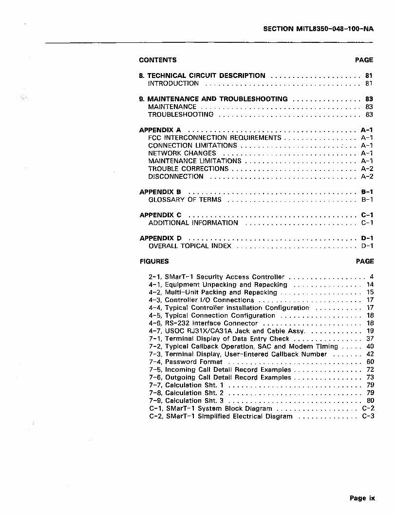
SECTION MITL8359-948-l OO-NA
CONTENTS PAGE
8.
9.
TECHNICAL CIRCUIT INTRODUCTION . . .
MAINTENANCE AND MAINTENANCE . . . . TROUBLESHOOTING
APPENDIX A . . . . . . .
DESCRIPTION ..................... 81 ................................. 81
TROUBLESHOOTING ................ 83 ................................. 83 ................................. 83
................................ A-l FCC INTERCONNECTION REQUIREMENTS ................. A-l CONNECTION LIMITATIONS ....................... ; ... A-l NETWORK CHANGES A-l MAINTENANCE LlMlTATlbJs : : : : : : : : : : : : : : : : : : : : : : : : : : A-l TROUBLE CORRECTIONS ............................. A-2 DISCONNECTION .................................. A-2
APPENDIX B ....................................... B-l GLOSSARY OFTERMS .............................. B-l
APPENDIX C ....................................... C-l ADDITIONAL INFORMATION .......................... C-l
APPENDIX D ....................................... D-l OVERALL TOPICAL INDEX ............................ D-l
FIGURES PAGE
2-1, SMarT-1 Security Access Controller .................. 4 4-1, Equipment Unpacking and Repacking ................ 14 4-2, Multi-Unit Packing and Repacking ................... 15 4-3, Controller I/O Connections ........................ 17 4-4, Typical Controller installation Configuration ........... 17 4-5, Typical Connection Configuration ................... 18 4-6, RS-232 Interface Connector ....................... 18 4-7, USOC RJ31X/CA3lA Jack and Cable Assy. ............ 19 7-1, Terminal Display of Data Entry Check ................ 37 7-2, Typical Callback Operation, SAC and Modem Timing ..... 40 7-3, Terminal Display, User-Entered Callback Number ....... 42 7-4, Password Format ............................... 60 7-5, Incoming Call Detail Record Examples ................ 72 7-6, Outgoing Call Detail Record Examples ................ 73 7-7, Calculation Sht. 1 ............................... 79 7-8, Calculation Sht. 2 ............................... 79 7-9, Calculation Sht. 3 ............................... 80 C-l, SMarT-1 System Block Diagram ................... C-2 C-2, SMarT-1 Simplified Electrical Diagram .............. C-3
Page ix

SECTION MITL8350-048-l OO-NA
TABLES PAGE
3-1, 3-2, 3-3, 4-1, 7-1, 7-2, 7-3, 7-4, 7-5, 7-6, 7-7, 7-8, 7-9,
SMarT-1 Hardware Specifications .................. 9,lO RS-232 Port Specifications ........................ 11 Electrical/Mechanical Specifications ................. 11 SMarT-1 Ordering Information ..................... 21 Initialization/Default Programming Parameters ........ 33,34 System Special Parameters ........................ 44 System Wide Operational Parameters .............. 47,48 Trunk Related Parameters ...................... 50-52 Non-Controller Pertinent Parameters .............. 55-57 Password Table Descriptions ...................... 6 1 Password Action Digits (a) ........................ 61 Time-Of-Day Codes (t) ........................... 61 Network Override Codes ........................ 63,64
7-10, Search Table Descriptions ........................ 65 7-11, Action Digit Descriptions ...................... 65,66 7-12, 6r5 Parameter Codes ......................... 67,68 7-13, Dialtone Detector Codes ......................... 68 7-14, ‘a’ Codes .................................... 69 7-l 5, ‘b’ Codes .................................... 69 7-16, Additional Route Parameters ...................... 70 7-17, MITEL Call Record Format Fields ................... 74 C-1,ASCll Codes .................................. C-4 C-2, Legal Controller Programming Input Characters ....... C-5 C-3, Default Parameter Summary ................ C-6 to C-8
Page x
SECTION MiTL8350-048-l OO-NA
1. INTRODUCTION
DOCUMENT OBJECTIVES
1 .Ol This document contains all information that relates to the SMarT-1’” Security Access Controller. The title of the Section is
the ‘SMarT- 1 tm SECURITY ACCESS CONTROLLER (SAC), General In- formation’ and can be referred to as ‘SECTION MITL8350-04%IOO-NA’ or by its title. This part of the Section is an overview of the contents of the document and outlines the intended audience.
1.02 From this point forward and for ease of understanding, the SMarT-I’” Security Access Controller (SAC) will be referred to .
in text as the ‘Controller’ or as the ‘SAC’.
DOCUMENT OVERVIEW
1.03 The document contains important notices to customers at the front on pages i through v. The first is for U.S. customers. The
second is for Canadian customers, while the third is general in nature. It is advisable to read the applicable notices prior to reading this manual or operating the Controller. If a particular notice does not apply, it may be removed from the manual.
1.04 Following the notices is a general Table of Contents. This Table lists all of the major parts of the manual, along with sub-
headings in the order that they appear. The manual is divided into 9 parts, with four appendices. The last Appendix is an overall index in alphanumeric order.
1.05 The first part is a general introduction and overview of the manual. The second is a description of the features and capa-
bilities of the SAC followed by a general unit description. The third lists all specifications of the unit.
1.06 The fourth part describes in detail, all procedures for receiving, shipping, unpacking, installation and connection of the Control-
ler. This is followed by a detailed operating description. The sixth part outlines unit initialization, while the seventh describes detailed pro- gramming. The eighth includes a technical circuit description, while the ninth lists maintenance and troubleshooting procedures.
1.07 The four appendices provide supplementary information that may be of some use to the user/programmer. The first appendix
describes FCC interconnection requirements and should be read by all installers. The second and third appendices contain a glossary of terms and additional information, respectively.
1.08 The last Appendix is an overall topical index listed in alphanu- meric order. This index lists a topic and the page where the
topic is discussed. It is included to provide an easy reference guide in locating specific information.
Page 1
SECTION MITL8350-048-l OO-NA
INTENDED AUDIENCE
1.09 This document is intended for use as a general information manual for the installer and user of the SMarT-1’” Security
Access Controller (SAC). It is also intended to be a technical descrip- tion of the SAC for programmers and other interested parties. The document does not attempt to teach programming concepts. It is assumed that the user has some programming experience.
DOCUMENT HISTORY
1.10 This is the second formal issue of the ‘SMarT-1’” Security Access Controller (SAC), General Information’. Subsequent is-
sues will be provided as information is changed or upgraded. These subsequent issues will replace any previous issue.
READER COMMENTS
1.11 If the user has any comments or corrections pertaining to this document, please forward a reply in writing to MITEL Docu-
mentation Control in Ogdensburg, N.Y. quoting document number ‘SECTION MlTL8350-048-00 1 -NA’.
DOCUMENT CONVENTIONS
1.12 Throughout this manual, the following conventions will be used:
SYMBOL MEANING
* . .
.
I[ II
A horizontal ellipsis means that the preceding item may be repeated one or more times.
A vertical ellipsis means that not all of the statements in a figure or an example are shown; their content is not important to the example.
Double square brackets in statement and format de- scriptions enclose items that are optional.
E 1 Braces enclose lists from which the user must choose one item. Each item is separated from the other by a comma ‘,‘.
<> The less than and greater than signs, used in statement -. and format descriptions, usually enclose a special key to be pressed, such as a carriage return <CR> key.
> The greater than sign, when appearing alone, indicates the terminal prompt as shown on the terminal display.
Terminal lines use two conventions. If the characters are printed in capitalized characters (upper case), the words are typed as listed. If they are printed in small characters (lower case), they require that some char- acter(s) be entered in their place.
Page 2

SECTION MlTL835Cb048-l OO-NA
2. GENERAL DESCRIPTION
FEATURES AND CAPABILITIES
The SMarT-1’” Security features and capabilities:
Access Controller has the following
Compliance with FCC Parts 68 and 15
4-, 2-, or l-Line capacity
A Stand Alone Device
Interfaces with Modems that are compatible with the Public Switched Network
Intercepts incoming calls without presenting a Modem Answer Tone
Verifiable password length
protection ranging from 2 to 15 digits in
Callback feature allows password to be associated to a specific dial back telephone number
Bypass of Callback feature (if required)
Manual entry of Callback number available through Class of Service
A maximum of 1000 Passwords/Callback numbers
Two sets of 4 carriers can be utilized to automatically process outgoing calls
Compatible with both Loop Start and Ground Start lines
Compatible with DTMF and Rotary Dial Central Offices
RS-232 Serial Data Port for administrative and maintenance purposes
Monitors activity on all lines to provide Call Detail Records (if required)
Non-Volatile Memory
Optional Progress Tones
Automatic disconnect on invalid codes
Time of day restriction
Optional use of Other Common Carriers (OCCs) for Callback
CONTROLLER DESCRIPTION
2.02 The SMarT-1’” Security Access Controller (SAC) is a powerful and compact system that provides advanced callback security
to most existing Modems without replacement of equipment. Through the use of password protection, the SAC provides the ability to secure
Page 3
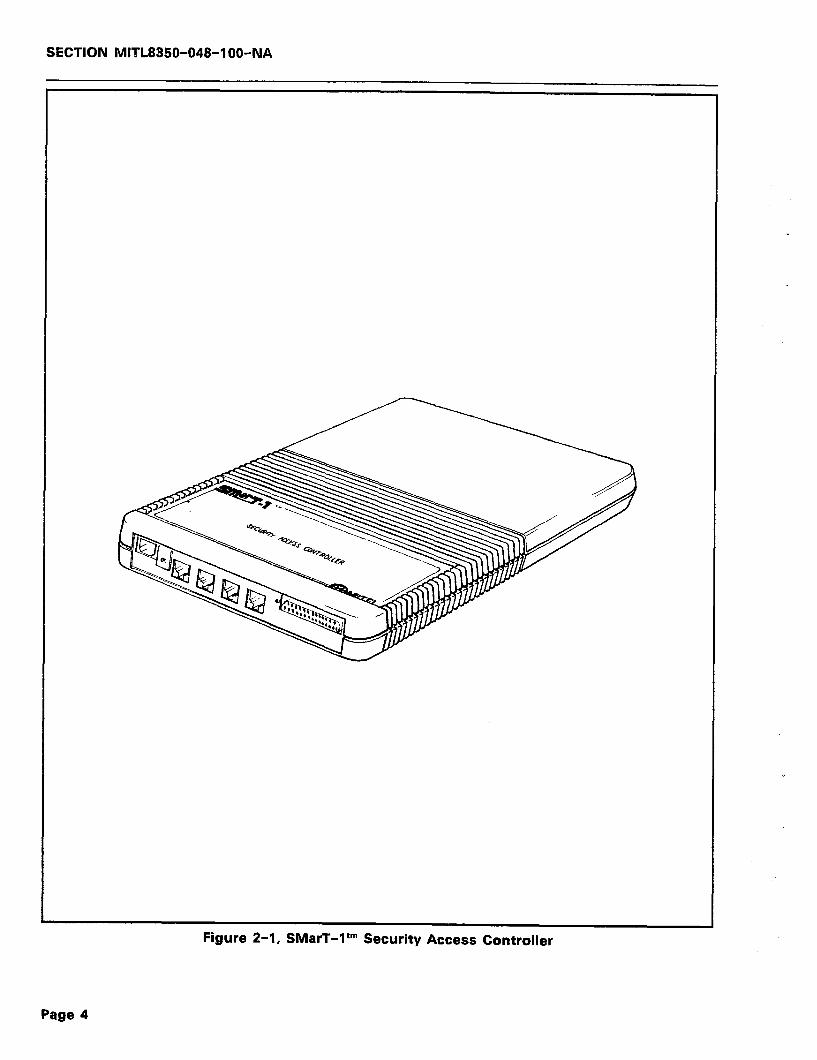
SECTION MITL8350-048-IOO-NA
Figure 2-1, SMarT-1 tm Security Access Controller
Page 4
SECTION MITL8350-048-l OO-NA
a data system and to allow access only to authorized personnel.
2.03 The Controller (see Figure 2-l) prevents unauthorized access to a data base that is typically gained through “hackers” utilizing
dial-up telephone circuits and randomly searching for authorization codes. The SAC security features include the disconnection of invalid access attempts and callback technology to protect the integrity of a network.
2.04 The Controller is typically installed on the telephone line be- tween the telephone company interface jack and the Modem of
the user’s system. This installation enables the SAC to prevent con- nection to the called Modem until it has a chance to verify the validity of the caller.
Network Compatibility
2.05 Telephone Trunks or Lines available to the user from the Cen- tral Office can be one of two types. These types are either
Ground Start or Loop Start. The Controller can be programmed to function with either type.
2.06 The available dialing types are typically DTMF or Rotary Dial. DTMF uses tones to dial while the Rotary system uses pulses.
The Controller can be programmed to function with either type on dial out. However, DTMF dialing is required for incoming calls.
System Power
2.07 Power is supplied from a small transformer that is provided with the system. In the event of a commercial power outage,
the SMarT-I’“’ Security Access Controller will assume a “power down cut-through mode”. In this state, the Controller appears to the network as a metallic path from its tip and ring inputs to its tip and ring outputs. In essence, the Controller in this mode will appear to not be present and allows all calls to pass.
2.08 Battery back up prevents memory loss in the event of a power failure. This feature, inherent in the Controller, allows the cus-
tomer’s stored data to be retained. There is no requirement for re- programming the Controller once power is restored.
Lines/Models
2.09 There are up to four independent lines in the Controller de- pending on the model used (4-, 2-, or l-line units). These lines
all share the same search tables. Results of searching through a table will select a route (in actuality, a ‘routing method’). The routing data (the four alternatives) is shared among the lines, thus providing pow- erful systems that gain simplified access to either a Modem or the common carrier network.
Page 5
SECTION MITL835C!-048-l OO-NA
Area Code/Office Code/Call Searching
2.10 The SMarT-I’” SAC can be programmed to ‘look up’ the Area Code (NPA) and Office Code (NXX) numbers and perform rout-
ing decisions (i.e., route through OCWReseller Switch, or route through DDD) depending on the OCWReseller’s capabilities and the customer’s requests.
Adaptive Call Routing
2.11 All calls are made over predetermined routes, with the required authorization codes being inserted automatically by the Con-
troller at the appropriate time. The Adaptive Call Routing (ACR) feature allows the Controller to automatically detect, remember and re-route all numbers not available on the OCC over to the DDD Network.
Least Cost Routing
2.12 Least Cost Routing allows the alternate routing of long distance calls through various OCC facilities. Since toll calls placed
through OCC networks are typically less expensive than DDD routes, choosing the most economical medium (i.e., DDD or whatever OCC) will enable the user to capitalize on OCC network rate benefits.
Call Recording/RS-232 Port
2.13 Call recording output is accomplished via the RS-232 (computer) port with a programmable Baud rate. This‘ output
provides a complete record of numbers dialed and the on- hook/off-hook times for all calls on the lines served by the system. This information can be utilized by the user for traffic studies, usage analysis, call costing, etc..
VERSATILE PROGRAMMING
Description
2.14 The SMarT-1’” Security Access Controller (SAC), as delivered from the factory, will require some programming before actual
use. In addition, the Controller may not have been initialized and may not have sufficient charge on the internal NI-CAD battery backup to ensure memory retention. This lack of charge may be due to storage ~ and transit times from the factory to the user.
2.15 To ensure that the unit is ready for operation, it should first be powered up for a period of time, then initialized followed by any
additional programming that may be required. The paragraphs that follow briefly describe this initialization procedure. For the complete and detailed initialization description, refer to Part 6, page 29.
Initialization
2.16 The SAC is initialized via the RS-232 port by use of a suitable
Page 6
SECTION MlTL8350-048-l OO-NA
terminal. Upon power on, the SAC monitors the RS-232 port for 7 seconds. During this time period, the unit expects to receive an ini- tialize command at a rate of 1200 Baud. This command consists of the two characters ‘AA’ and must be entered from the keyboard (in upper case only).
2.17 If, after 7 seconds, the initialize command is not received, the SAC will check its internal memory for the programmed Baud
rate (1200 Baud by default) and switch to that Baud rate.
2.18 Initialization of the SAC will load a database for automatic callback operation. The SAC will have the following commu-
nications requirements:
1) 2) 3)
4)
5)
Note:
1200 Baud Rate
No Parity
8 bit Characters with one Stop Bit
Bit 8 Sense = SPACE
Full Duplex Communications at the RS-232 Port.
Refer to Part 4, page 16 for a complete description of the RS-232 Port connection and communications requirements.
* Programming
2.19 The Controller will require some programming after initializa- tion. The unit will not require re-initialization except under fault
conditions. For a complete description of programming, refer to Part 7, page 33. If the ‘default’ programming is desired, it may be selected by entering a ‘load default’ command after initialization. This command is ‘942903’. The command will restore all defaults as listed in Part 7. For specific programming, refer to Part 7, page 42.
Page 7
SECTION MITL8350-048-l OO-NA
--- THIS PAGE INTENTIONALLY LEFT BLANK ---
Page 8
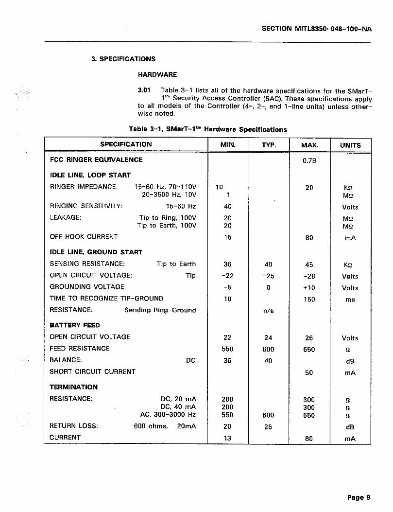
SECTION lVlITL8350-048-l OO-NA
3. SPECIFICATIONS
HARDWARE
3.01 Table 3-1 lists all of the hardware specifications for the SMarT- ltm Security Access Controller (SAC). These specifications apply
to all models of the Controller (4-, 2-, and l-line units) unless other- wise noted.
Table 3-1, SMarT-1’” Hardware Specifications
SPECIFICATION
FCC RINGER EQUIVALENCE
IDLE LINE, LOOP START
RINGER IMPEDANCE: 15-60 Hz, 70-11OV 20-3500 Hz, IOV
RINGING SENSITIVITY: 15-60 Hz
LEAKAGE: Tip to Ring, 1OOV Tip to Earth, IOOV
OFF HOOK CURRENT
IDLE LINE, GROUND START
SENSING RESISTANCE: Tip to Earth
OPEN CIRCUIT VOLTAGE: Tip
GROUNDING VOLTAGE
TIME TO RECOGNIZE TIP-GROUND
RESISTANCE: Sending Ring-Ground
BATTERY FEED
OPEN CIRCUIT VOLTAGE
FEED RESISTANCE
BALANCE: DC
SHORT CIRCUIT CURRENT
TERMINATION
RESISTANCE: DC, 20 mA DC, 40 mA
AC, 300-3000 Hz
RETURN LOSS: 600 ohms, 20mA
CURRENT
MIN.
10 1
40
20 20
15
36
-22
-5
10
22
550
36
200 200 550
20
13
TYP.
40
-25
0
n/a
24
600
40
600
26
MAX.
0.7B
20
80
45
-28
+10
150
26
650
50
300 300 650
80
UNITS
Ka Mfi
Volts
M& Mfi
mA
Kfi .
Volts
Volts
ms
Volts
fi
dB
mA
fi fi a
dB
mA
Page g

SECTIQN MITL8350-048-l OO-NA
Table 3-l (Cont’d), SMarT-1’” Hardware Specifications
SPECIFICATION
DIAL TONE
CO SIDE FEED: Gain 300 Hz
INTERNAL FEED: 350 Hz
DTMF RECEIVER
LEVEL
LEVEL DIFFERENCE
FREQ: To receive To not receive
DURATION
TIME BETWEEN TONES
ROTARY RECEIVER
MAKE IMPEDANCE
MAKE DURATION
BREAK IMPEDANCE
BREAK DURATION
RATE
DTMF SENDER
LEVEL
FREQUENCY
DURATION (Programmable)
ROTARY SENDER
TIMING (Programmable)
TIMING (At 60/40): Make Break
RATE (At 60/40)
INTERDIGIT PAUSE (Programmable)
OPERATING RANGE
TEMPERATURE
HUMIDITY
ALLOWABLE VOLTAGE: connected to any point
t With reference to 6OOa Termination.
MIN.
-2
-20
-6
-1.5 -3.5
40
30
20
8
20
7
-8
-1.3
40
40/30
35 55
9.9
400
0
0
TYP.
0
n/a
-6
60
60/40
10
800
MAX.
+2
+3
+6
+I.5 +3.5
700
100
100
20
-3
+I.3
130
60/40
45 65
10.1
1300
55
85
300
UNITS
CiB
dBmt
dB
% %
ms
ms
Q
ms
K!Z
ms *.
PPS
dBmt
%
ms
ms/ms
ms ms
PPS
ms
“C
%
Volts
Page 10

SECTION MlTL8350-048-l OO-NA
PARAMETER
BAUD RATE:
PARITY:
BITS PER CHARACTER:
BIT EIGHT SENSE:
MODE:
OPERATION:
RS-232 PORT
3.02 Table 3-2 below contains the specifications for the SMarT-I’” Security Access Controller RS-232 Auxiliary Port. This port may
be used for programming or for SMDR Output.
Table 3-2, RS-232 Port Specifications
SPECIFICATION
300 to 9600 Baud programmable; default = 1200 Baud
None
Eight bits per character with one stop bit.
Space
On line.
Full duplex mode.
ELECTRICAL/MECHANICAL
3.03 Table 3-3 contains the Electrical and Mechanical specifications for the SMarT-1’” Security Access Controller. These specifica-
tions apply to all models of the Controller (4-, 2-, and l-line units) unless otherwise noted.
PARAMETER
DIMENSIONS:
WEIGHT: Dialer
Power Supply
MOUNTING:
POWER:
Range:
CONNECTIONS:
3.04 This section does not contain all of the specifications for the Controller at present. Other specifications will be added as they
are received.
Table 3-3, Electrical/Mechanical Specifications
SPECIFICATION
7.625” (19.37cm) Wide X 10.625” (26.99cm) H X 1.375” (3.49cm) D
2 Ibs (0.907 kg)
1 lb (0.453 kg) (Approximately)
Wall Mount with Supplied Bracket
115 Volts AC, 60 Hz @? 300 mA
103.5 to 126.5 VAC
Standard RJ31WCA31A Network Connec- tions
Page 11
SECTION MlTL8350-048-IOO-NA
3.05 The specifications in the Tables above are subject to change without notice. The inclusion of ‘n/a’ for a specific parameter
means that the specification is not available at the time of this pub- lication. It will be added at a later date.
Page 12

SECTION MITL8350-048-l OO-NA
4. UNPACKING, INSTALLATION AND ORDERING INFORMATION
SHIPPING AND RECEIVING
4.01 The SMarT-1’” Security Access Controller is shipped in a single carton that contains the Controller, the Power Supply, a Wall
Mounting Bracket, four RJ31XKA31A Cables and appropriate docu- mentation. All of these items are protected within the carton by styro- foam inserts.
Note: Some production units do not require the wall mounting brackets since these units are mounted to a wall by use of keyslots included on the unit case.
4.02 In some instances where more than one unit is shipped, a larger carton may be used that would contain five of the small-
er cartons. Each of the smaller cartons would contain the items listed in 4.01 above.
Unpacking
4.03 The procedure below lists steps to take when unpacking the equipment (refer to Figures 4-1 and 4-2):
1) Open carton and remove contents.
2) Check each item removed for damage.
3) Check each item against the packing list.
4) Notify the vendor if any items are missing or appear to be damaged or defective.
Repacking
4.04 If an item is found to be defective or damaged and is to be returned to the vendor, it should be tagged and packaged to
prevent damage. If units are to be shipped from one location to another, these units should also be packaged in such a manner as to prevent damage. Figure 4-l shows how the equipment was originally packed. This method of packaging should be followed as closely as possible.
4.05 If the original packaging material is no longer available, the returned parts should be wrapped in several layers of air-
cushion type of wrap, placed in a suitable container, and surrounded with paper to minimize the movement of the items.
INSTALLATION REQUIREMENTS
4.06 The SMarT-1’” SAC is position independent. It may be mounted anywhere that will accommodate the unit size as listed in the
specifications In Table 3-3 on Page 11.
Page 13
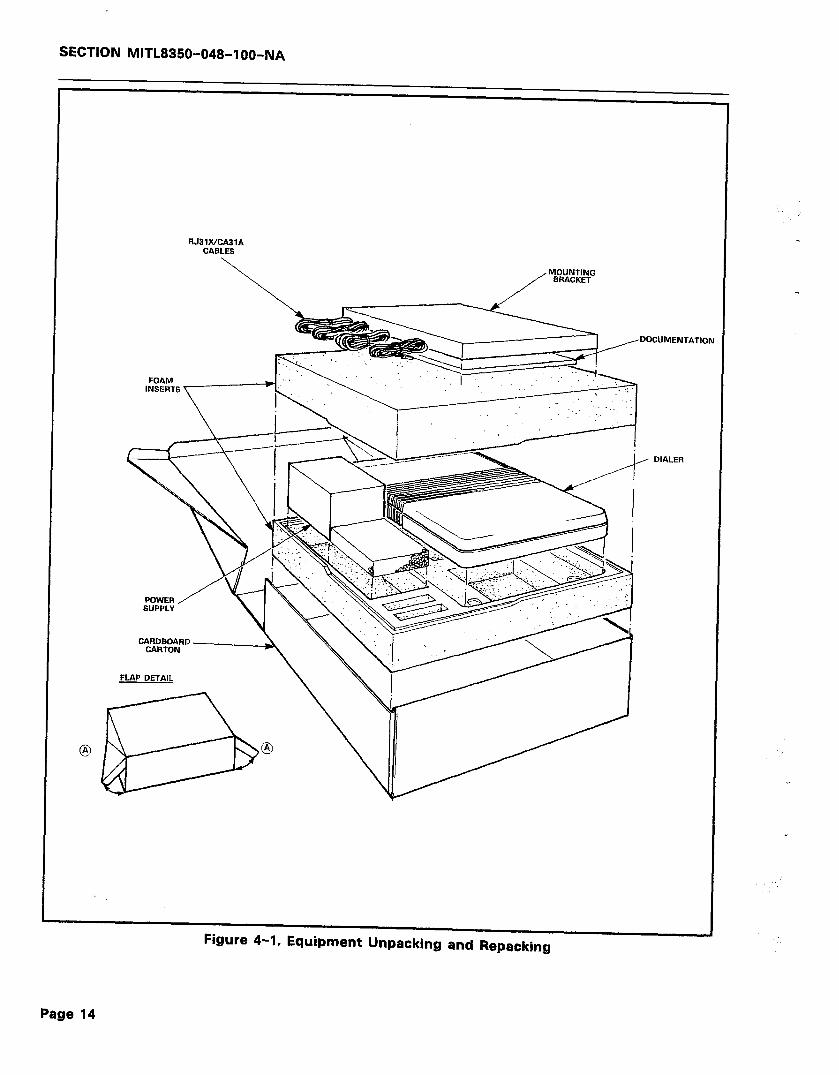
SECTION MITL8350-048-l OO-NA
RJ31WCA3lA CABLES
\
DOCUMENl -ATlOh I
--I DIALER
Figure 4-1, Equipment Unpacking and Repacking .
H.AI’ DETAIL
Page 14
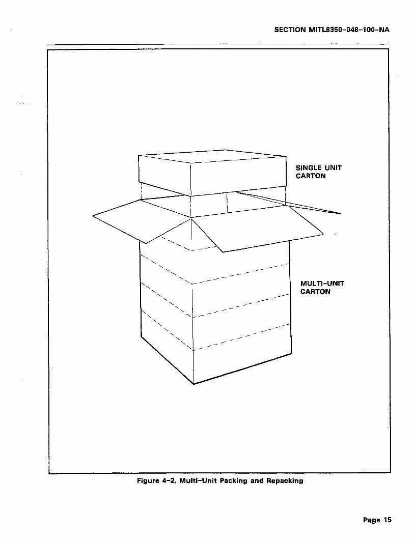
SECTION MlTL8850-048-l OO-NA
SINGLE UNIT CARTON
‘\ \ /-- \ /-- \ /- \ _-- \__--
\ / MULTI-UNIT CARTON
Figure 4-2, Multi-Unit Packing and Repacking
Page 15
SECTION MITL8350-048-l OO-NA
4.07 The SAC will operate within a 0-55°C temperature and a 0435% humidity range.
POWER REQUIREMENTS
4.08 The customer must provide a single phase power receptacle with the following recommendations:
.: ::
115V, 60Hz fused and capable of delivering 350mA per unit installed.
The power receptacle should be wired and fused independently from all other receptacles that are not controller related.
A warning tag should be attached to circuit breaker type fuses to prevent unauthorized manual operation.
The power receptacle should not be controlled by a switch.
The live and neutral conductors at the receptacle should be wired to their proper respective connections.
The power receptacle must be a 3-wire type, with the ground wire connected to the ground of the electrical system.
The receptacle should be easily accessible for the removal of the plug for maintenance.
The receptacle location should be selected to prevent acciden- tal removal of the power cord.
The power cord between the receptacle and the unit should not present a hazard to the user.
MOUNTING
4.09 If the unit requires the wall mounting bracket, simply mount the bracket to a surface with screws. Mount the Controller housing
to the bracket by matching the four holes on the rear of the case with the mounting pins of the bracket. Press firmly into place.
4.10 If the unit is the keyslot type, mount by using the provided template to find screw locations. Insert #6 X 3/4 wood or self-
tapping screws in these locations, leaving approximately l/8 inch gap between the surface and the cap-head. Mount the Controller by posi- tioning the keyslots over the screw heads, pressing toward and then down from the mounting surface.
-‘.
CONNECTIONS
Note: The Security Access Controller should be initialized prior to accomplishing any connections. Refer to Part 6, paragraph 6.06 for the initialization procedure.
4.11 Connections to the Controller are made at the Connector Panel located along the bottom edge of the housing. Figure 4-3 illus-
trates the connection panel. The steps below outline the connection
Page 16

SECTION MITL8350-048-l OO-Nk
/ COMPUTER PORT (RS-232)
[Dl
Figure 4-3, Controller I/O Connections
SMART-l CONTROLLER
POWER SUPPLY
RJ2lX CA3lA
Figure 4-4, Typical Controller Installation Configuration
Page 17

SECTION WTL8350-048-100-NA
CENTRAL OFFICE LINES
MDF DF CENTRAL OFFICE “SPLIT” TYPE
DEMARC. STATION BLOCK
MODEM OR OTHER PROTECTED
EQUIPMENT
- -- _ - -- - - -- _
“66 BLOCK” OR RJZlX
MDF OR CA21A
(T) TIP (R) RING
- -- _
RJ3lX CA318
Figure 4-5, Typical Connection Configuration
Figure 4-6, W-232 Interface Connector (Viewed from outside Dialer)
pllJl SIGNAL
1 FRAME GND 2 RxD (Signal in) 3 TxD (Signal Out)
4,5 TIED TOGETHER 6,8,20 TIED TOGETHER
7 GND
Page 18

SECTION MITL8350-048-100-NA
Figure 4-7, USOC RJ31WCA31A Jack and Cable Assy.
Page 19
SECTION MITL8350-048-l OO-NA
procedure:
1)
2)
3)
4)
5)
6)
7)
4.12 This completes the mechanical installation of the SMarT-1’” Security Access Controller. Continue by programming the unit
from the terminal.
Refer to Figure 4-3. Connect a suitable Earth Ground to the screw mount [Al provided on the connector panel. This connec- tion MUST be made for the unit to function properly.
Plug the Power Pack jack into the Controller power connection [Bl.
Plug the Power Pack AC line cord into a suitable (1 IOV-60Hz) AC receptacle.
Using the supplied RJ31XKA31A cables, insert one end of a cable in a jack on the Controller [Cl.
Connect the other end of the cable used in step 4 to the Telco-supplied jack.
Repeat steps 4 and 5 above for the appropriate number of times depending upon the model of Controller being installed (4-, 2-, or l-line units).
Connect a suitable terminal to the RS-232 Computer Port [Dl via a suitable cable. Configuration of this cable is described in paragraph 4.13 below.
RS-232 Port Configuration
4.13 The RS-232 Computer Port connector (refer to Figure 4-6) is a female connector configured as “DCE”. Only the TxD (pin 3), the
RxD (pin 2), and the GND (pin 1) lines are used by the Controller. Pins 4 through 6, 8, and 20 are shorted internally for the convenience of the user. This port is used for programming and call recording output.
4.14 During programming, a suitable terminal must be connected to this port. For call recording output, a suitable printer is con-
nected in place of the terminal. Refer to Part 6 paragraph 6.05 for the configuration of the terminal or the printer.
RJBlWCA31A USOC Jack and Cable
4.15 Figure 4-7 illustrates the USOC RJ31XKA31A Connector and ,,
cable assembly as used by the SAC. Figure 4-5 illustrates the installation wiring of the Telco-supplied RJ31XKABlA USOC jack and other connections from the Central Office through to the Modem or i
other protected equipment. For the unit to operate properly, the bridge clips at the “split” type station block must be removed.
Page 20

SECTION MITL8350-048-100-N/I
ORDERING INFORMATION
4.15 Table 4-l on the following page lists the part numbers and descriptions of items that can be ordered from MITEL DATA-
COM INC.
Table 4-1, SMarT-1 tm Ordering Information 4-1, SMarT-1 Ordering Information
PART NO.
8350-007 SMarT-1’“:
DESCRIPTION
4 Line Security Access Controller. Includes Power Pack, RJ31 Cables, and Mounting Hardware.
8350-008 SMarT-1 tm: 2 Line Security Access Controller. Includes Power Pack, RJ31 Cables, and Mounting Hardware.
8350-009 SMarT-1’“: 1 Line Security Access Controller. Includes Power Pack, RJ31 Cables, and Mounting Hardware.
SPARES
8350-010 Wall Mount Bracket for SMarT-1’” Security Access Controllers.
8350-012 Power Pack for SMarT-1’” Security Access Controllers.
8350-013 RJ31XKA31A Cable for SMarT-1’” Security Access Controllers.
8350-048- 100-NA General Information Manual.
8350-953-003-NA SAC Maintenance Programming Guide.
Page 21

SECTION MITL8350-048-l OO-NA
--- THIS PAGE INTENTIONALLY LEFT BLANK ---
Page 22
SECTION MITL8350-048-IOO-NA
5. OPERATING DESCRIPTION
SECURITY
5.01 The primary function of the SMarT-1’” Security Access Control- ler (SAC) is to provide security to connected systems such as
Modems and to protect these systems from unauthorized telephone access. The security provided by the SAC lies in three distinct areas. These areas are:
l The use of optional progress tones, or lack thereof, to make it difficult for an unauthorized caller to recognize that there is protected equipment connected to the telephone line.
0 The inclusion of the callback feature to assure that only those individuals with valid passwords are called back at an assigned number associated with that particular password.
0 Finally, the provision of a call detail record that is available at the RS-232 Computer Port to record the time and duration of the call, along with the number that was called back.
5.02 While it is not recommended, the SAC may also be pro- grammed to allow instant access (circumvention of the call
back feature) upon the- receipt of a particular password.
5.03 Passwords must be Dual-Tone Multifrequency (DTMF) digit strings that range from 1 to 15 digits in length. Only a DTMF
type of telephone can be used to access the SAC. Rotary dial tele- phones cannot be used since rotary digits can only be received by, but not transmitted through, a Central Office.
OPERATIONAL SEQUENCES
5.04 The steps listed below show the operational sequences of the Controller:
Note: A single progress tone as used in the steps below indicates that the user will hear a single ‘beep’ in the receiver earpiece of the telephone. In a like manner, a double progress tone means two ‘beeps’ and a triple progress tone means three ‘beeps’.
1) The user dials the directory telephone number of the protected device with a DTMF type telephone.
2) The SAC detects the incoming call, disconnects the protected equipment from the line, and answers the call. The SAC may then optionally provide the user with a single progress tone.
3) The user enters his/her password by keying the correct digits on the telephone. This password may be from 1 to 15 digits in length and consists of any of the 12 standard DTMF digits.
4) If an exact match for the password cannot be found in the SAC
Page 23
SECTION MITL8350-048-IOO-NA
5)
6)
internal memory, the Controller drops the line (hangs up) and may optionally “busy out” that particular line for a program- mable length of time. The unsuccessful password will be print- ed in the Call Detail Record.
If an exact match for the password is found in the SAC internal memory, the Controller will check for the type of access that the password permits, including the time-of-day period as- signed for that particular access.
Upon verification of a valid password during the particular time-of-day period, the SAC will then execute its programmed action for that particular password. One of three series of events will occur:
?
Automatic Callback Access:
a) The password action is deemed to be an automatic call- back. For this instance, the SAC will hang up the tele- phone line, reseize the line and dial back to the user by using a preprogrammed call back number associated with this particular password. The user must know that he has to hang up, or may optionally be requested to hang up by receipt of a triple progress tone ,from the Controller. This method of access is considered to be the most secure making it nearly impossible for some- one to gain unauthorized access to the protected equip- ment.
User Entered Callback Access:
b) The password action is deemed to be a user controlled callback type. This means that the user must manually tell the controller the telephone number to be used for the callback. The user either must know when to enter his telephone number and hang up, or may optionally be requested to input his telephone number by receipt of a double progress tone, and to hang up on receipt of a triple progress tone. As before, the SAC will then hang up and reseize the line. It will dial out using the user entered telephone number. This action is less secure that the previous action since the user provides the telephone number. However, the call detail record will contain the telephone number that the user has entered and was called back at.
Cut-Through Access:
c) The password action is deemed to be a ‘cut-through’ type of access. In this case, there will be no progress tones received or any other SAC activity. At the expira- tion of the ‘wait for password’ time period, the SAC will connect the caller to the protected device. This action is the least secure of the three actions. While the password must be entered exactly and the access attempt made
Page 24
SECTION MlTL8350-048-l OO-NA
during the allowed time-of-day, there will be no record of the call with the exception of the time and duration of the access and the optional printing of the successful password.
DETAILED OPERATING DESCRIPTION
With Modems
5.05 The following assumptions are taken into consideration when describing the detailed operating procedures that will follow in
paragraph 5.06:
1)
2)
3)
There are correctly installed and known functional Modem con- nections for the Central Processing Unit (CPU) and the remote access. Any installation should first be capable of functioning without the SAC device present to cut down on non-SAC re- lated operational questions.
If installation problems are encountered at any time, the SAC device should be removed to prove that connections are possi- ble without the device. Otherwise, considerable effort could be expended when the problem is in other areas of the system.
Persons accessing the system (users) have been previously advised of any necessary sequence of events required in order to establish a valid Modem connection. In some instances, spe- cialized sequences will be required.
Automatic Callback Access
5.06
cess:
1)
2)
3)
Note:
The following steps outline the operations of the Security Ac- cess Controller that occur when using automatic callback ac-
The caller dials the host system over the telephone lines.
The protected Modem senses ringing and seizes the line. With proper programming, the SAC then splits the line while the protected Modem is waiting for the line to settle (about 2 seconds). The Modem (at the end of the line settling period) places an answer tone on its output to the SAC. The SAC emits a single progress tone to the caller. No Modem tones are supplied to the caller.
The caller, after hearing the progress tone (unless disabled), must enter the assigned password via DTMF dialing. Two con- ditions must be satisfied at this point. The first is that the protected Modem must be capable of answering in the answer mode for a programmable period of time that is sufficient to allow the callback to occur. The second is that the called back Modem must be capable of being forced into the originate mode upon receipt of the callback.
A more efficient variation of the above description would be that the protected Modem answer the incoming call in the
Page 25

SECTION MITL8350-048-IOO-NA
4)
5)
6)
7)
Note:
originate mode (waiting for answer tone) for a period of time long enough to allow the callback to occur, as previously mentioned. In this case, the callback could be automatically answered by the Modem that is accessing the host system. These events depend upon the sophistication of the Modems and the ingenuity of the user.
After a programmable period of time, the SAC will drop the line. The SAC will reseize the line if the password is valid, and will dial back the caller via the use of speed dialing.
If the protected Modem is waiting for an originate tone (via programming), the calling Modem may simply answer the call automatically, thus establishing the connection. The SAC will cut-through upon the completion of it’s call back and connect the two Modems.
If the called Modem is waiting in the answer mode (most common used mode), the caller must place his Modem into the originate mode upon receipt of the callback.
Once connection is established, the SAC ‘goes to sleep’ and appears as a direct through connection to the two Modems. Call disconnection is accomplished as per normal operation, or at a loss of carrier detect at either Modem.
In the 2- and 4-line models, the SAC is continually monitoring the other unused lines while the above procedure is taking place.
User-Entered Callback Access
5.07 The following steps outline the operations of the Security Ac- cess Controller that occur when using user entered callback
access:
1) The caller dials the host system over the telephone lines.
2) The protected Modem senses ringing and seizes the line. With proper programming, the SAC then splits the line while the protected Modem is waiting for the line to settle (about 2 seconds). The Modem (at the end of the line settling period) places an answer tone on its output to the SAC. The SAC emits a single progress tone to the caller. No Modem tones are supplied to the caller. Two conditions must be satisfied at this point. The first’ is that the protected Modem must be capable of answering in the answer mode for a programmable period of time that is sufficient to allow the callback to occur. The second is that the called back Modem must be capable of being forced into the originate mode upon receipt of the callback.
3) The caller, after hearing the progress tone (unless disabled), must enter the assigned password via DTMF dialing. Upon vali- dation of the password, the SAC will emit a double progress tone to the caller.
4) The caller, after hearing the double progress tone (unless dis-
Page 26
SECTION MITL8850-048-l OO-NA
_I . ..
:
Note:
5)
6)
7)
8)
Note:
abled), must enter the telephone number for callback by DTMF dialing. Two conditions must be satisfied at this point. The first is that the protected Modem must be capable of answering in the answer mode for a programmable period of time that is sufficient to allow the callback to occur. The second is that the called back Modem must be capable of being forced into the originate mode upon receipt of the callback.
A more efficient variation of the above description would be that the protected Modem answer the incoming call in the originate mode (waiting for answer tone) for a period of time long enough to allow the callback to occur, as previously mentioned. In this case, the callback could be automatically answered by the Modem that is accessing the host system. These events depend upon the sophistication of the Modems and the ingenuity of the user.
After a programmable period of time, the SAC will drop the line. The SAC will reseize the line if the password is valid, and will dial back the caller using the number just accessed.
If the protected Modem is waiting for an originate tone (via programming), the calling Modem may simply answer the call automatically, thus establishing the connection. The SAC will cut-through upon the completion of it’s call back and connect the two Modems.
If the called Modem is waiting in the answer mode (most common used mode), the caller must place his Modem into the originate mode upon receipt of the callback.
Once connection is established, the SAC ‘goes to sleep’ and appears as a direct through connection to the two Modems. Call disconnection is accomplished as per normal operation, or at a loss of carrier detect at either Modem.
In the 2- and 4-line models, the SAC is continually monitoring the other unused lines while the above procedure is taking place.
Cut Through Access
5.08 The following steps outline the operations of the Security Ac- cess Controller that occur when using access via Cut Through
Access:
1) The caller dials the host system via the telephone line.
2) The protected Modem senses ringing and seizes the line.
3) With proper programming, the SAC splits the line while the protected Modem is waiting for the line to settle (approximately 2 seconds). After line settling, the protected Modem places an answer tone at its output. No Modem tones are supplied to the caller.
4) The answering Modem must remain on the line while the caller,
Page 27

SECTION MITL8350-048-l OO-NA
after hearing the single progress tone (unless disabled) enters his assigned password via DTMF dialing.
5) Upon verification of the password, the SAC will cut-through (connect the caller to the protected Modem). The calling Mo- dem will respond with an originate tone that establishes the connection. Except for the slight pause required to enter the caller’s password, this is a standard access and requires no special considerations. The only constraint is that a valid pass- word must be entered within a predetermined length of time. Failure to enter the password within this time frame (determined by the answering Modem and/or SAC constraints programmed as desired) would result in the line being dropped and the access failing.
6) Once the connection is established, the SAC device ‘goes to sleep’ and appears as a direct connection between the two Modems. Modem disconnection is established as per normal routines or at a loss of carrier detect at either Modem.
Other Operational Procedures
5.08 Other operational procedures or applications depend on the type of equipment being protected and the related operating
conditions. In all applications, the three basic modes of access in descending order of security are:
0 Automatic Callback on Valid Password
0 Callback to User Entered Number on Valid Password
0 Connection upon Receipt of Valid Password.
Page 28
SECTION MITL8350-048-l OO-NA
6. INITIALIZATION
INTRODUCTION
6.01 Initialization is the procedure that readies the SMarT-1’” Secu- rity Access Controller for initial programming. This procedure
has been detailed previously in Part 2 of this document. Since it is a very important procedure, it will be listed again in this part in detail.
6.02 There are several reasons for accomplishing initialization of the SAC. These are a) that the Controller has just been removed
from storage or has just been received, or b) the program access codes have been deleted accidentally or the access codes have been changed and forgotten, or c) the Controller has just been repaired, or d) the Controller has been stored for a long period of time, or e) the Controller has had a loss of data retention.
Note: If the reason for initialization is e) above, it is recommended that the reason for loss of data retention be found and cor- rected.
6.03 Once. initialized, the Controller should seldom require re- initialization. After initialization, the Controller may be pro-
grammed by use of a suitable terminal. A default data base may be loaded by issuing a command via this terminal.
6.04 Prior to injtialization, ensure that the Controller has been pow- ered on for a sufficient period of time to allow the internal
NI-CAD battery to be charged. This period should be approximately 24 hours long. The battery protects the memory against loss of data during power outages and will sustain the memory for several days, once charged.
6.05 Initialization is accomplished by use of a suitable terminal con- nected to the RS-232 Computer Port. A suitable terminal is
defined as one that meets the following criteria:
1) Capable of transmitting and receiving at 1200 Baud.
2) No parity
3) 8 bit characters with one stop bit
4) Bit 8 sense = SPACE’
5) Full Duplex communications
6) Connection to the RS-232 Computer Port with a suitable cable configured as “DCE” with the following pin connections:
a) Pins 1 and 7 = GROUND b) Pin 2 = RxD (Signal in) c) Pin 3 = TxD (Signal out) d) Pins 4 and 5 = Tied together e) Pins 6, 8, and 20 = Tied together.
Page 29
SECTION MITL8350-048-l OO-NA
Note: The Security Access Controller does not respond to DTR, RTS, etc..
PROCEDURE
6.06 The steps below show the procedure to be followed to initialize the Controller:
1) Power the SAC off.
2) Connect a suitable terminal to the RS-232 Computer Port.
3) Power the terminal on and set for the required parameters (if . .
required).
4) Power the SAC on. Once on, the Controller will monitor the RS-232 Computer Port for a period of 7 seconds.
5) During this 7 second period, enter the characters ‘AA’ from the terminal keyboard (in upper case only). Within another 7 second period, the SAC should respond with:
REV xx-xx ENTERING PROG. MODE
where ‘xx-xx’ is the revision of the software resident in the controller. Once this message has appeared, the SAC is in the programming mode.
*
Note: The SAC should not be powered down while it is in the programming mode as it will cause the unit to print checksum errors on the next power up sequence.
6.07 If, after 7 seconds, the initialize command is not received, the SAC will check its internal memory for the programmed Baud
rate (1200 Baud by default) and switch the RS-232 Computer Port to that rate.
6.08 Initialization of the SAC will load a complete database for auto- matic callback operation with the following communications
parameters:
1) 1200 Baud Rate
2) No Parity
3) 8 bit Characters with one Stop Bit
4) Bit 8 Sense = SPACE
5) Full Duplex Communications
6.09 Once initialized, programming may be immediately started via the terminal. The user may elect to exit the programming mode
by entering ‘999’ on the terminal keyboard. If ‘999’ is entered, the SAC will respond on the terminal display with:
QUITTING PROG. MODE..
Page 30

SECTION MITL8350-048-IOO-NA
Note: Pressing <CR> on the keyboard will not allow programming if the default Terminal Program Access Code (<CR>) has been changed. Refer to Part 7, Programming for more details.
6.10 If nothing is entered on the terminal keyboard for a period of 1 minute, the SAC will automatically print on the terminal display:
WARNING . . . LOGOUT IN 60s.
and 1 minute later, the SAC will automatically exit the programming mode.
Page 31
SECTION MITL8350-048-IOO-NA
--- THIS PAGE INTENTIONALLY LEFT BLANK ---
Page 32

SECTION MITL8350-048-IOO-NA
7. PROGRAMMING
INTRODUCTION
7.01 Prior to using the SMarT-I’” Security Access Controller, some basic programming must be entered into the unit. This basic
programming provides the Controller with the date, time, passwords, and other fundamental information that is pertinent to the operation of the unit. The parameters to be programmed depend on the type of operation that is expected of the Controller.
Note: Before programming the unit, ensure that it has been ini- tialized and powered on long enough to charge the internal battery. For more information on initializing, refer to Part 6, page 29.
7.02 Initializing the SMarT-1’” Security Access Controller will pro- vide the unit with part of the basic programming that is per-
tinent to the operation. This initialization procedure will cause the unit to be programmed as listed in Table 7-l below. The table also lists the associated parameter label that applies to the default data.
Table 7-1, Initialization/Default Programming Parameters
DEFAULT DESCRIPTION- ASSOCIATED PARAMETER
LABEL
INTERNAL CLOCK = No time or date entered
PASSWORD DATA = No passwords present
ACCESS CONTROL SEQUENCE = Callbacks are dialed to the DDD Net- work
CALLBACK NUMBER DATA = No callback numbers present
TYPE OF CENTRAL OFFICE = Loop Start DTMF Digit output
PRINTER BAUD RATE = 1200 Baud RS-232 Communications Fixed: No parity
8-bit words Bit 8 Sense = SPACE Full duplex On line
980
821 thru 835
6r5
7nnn
xoot xoot
006t
PRINT FORMAT = Call Detail Record in SMART Format
AUTO ANSWER TIMER = Automatically answer incoming calls in 3 seconds
WAIT FOR PASSWORD TIMER = Wait 8 seconds for password entry
(Continued)
009t
x27t
x28t
Page 33

SECTION MlTL8350-048-l OO-NA
Table 7-l (Cont’d), initialization/Default Programming Parameters
ASSOCIATED DEFAULT DESCRIPTION PARAMETER
LABEL
AUTO ANSWER LOCKOUT TIMER = “Busy Out” line for 20 seconds on invalid password
TONE OPTIONS = Single tone to request password “ON” Double tone to request callback number “ON”
Triple tone to request caller hang up “ON”
DIALBACK TIMER = Wait for 5 seconds before initiating callback
MACHINE IDENTIFIER = “SAC”
TERMINAL PROGRAM SECURITY CODE = “<CR>”
NAME OF ROUTE = “DDD”
No “Other Common Carrier” programming is in default.
x29t
x35t x35t
x35t
x36t
602
604
6rO
Note: The letter ‘x’ or ‘r’ in the parameter label represents a single user selectable character for entry to select a specific part of the parameter. The letter ‘t’ represents a digit that selects a specific operation of the parameter.
7.03 While the default parameters listed in the Table 7-l above is not a complete listing of all of the parameters that are resident
in the Controller, they are the ones that are the most pertinent to unit operation. The remaining parameters (not listed in the table) are set to defaults that will work in nearly all applications. These other param- eters are programmable for those times when “standard” conditions of the telephone lines or dialing patterns are not present.
PROGRAMMING FOR CALLBACK OPERATION
7.04 Programming is accomplished from a terminal attached to the RS-232 Computer Port of the Controller. Programming consists
of entering a parameter identifier consisting of three or more digits, followed by a data string and an entry terminator (if required). For example, if the unit were in the programming mode and it is desired to program the time and date, the parameter ‘980’ would be entered. This parameter would be followed by the month, day, hour, and minutes entered as a digit string. The string would be composed of four, two digit groups for the date and time. This string does not require a terminator and the Controller would automatically accept and enter the terminal data.
TERMINAL
>
PARAMETER
D801
USER DATA 1 TERMINATOR
[mmddhhmm] (none)
Page 34

SECTION MITL8350-048-l OO-NA
NOTES ON DATA ENTRY
Whenever the Controller knows the length of a parameter entry, the entry will automatically be accepted by the SAC without the need of following the entry with a terminator. For string type entries of unknown length (to the SAC), a terminator of ‘BB’ or ‘FF’ must be entered to identify the end of the entry. Technically, ‘BB’, ‘FF’, and ‘. .’ are all internally interpreted as the same digit (see Table C-2, page C-5). The last character of an ASCII string may not be ‘B’. However, a single ‘B’ within a string is allowed. If the last character of an ASCII string must be ‘B’, then it must be followed with a nonprinting character such as a <SPACE> (hexadecimal 20). If necessary, the <LF>, <FF>, <CR>, <BEL> and so on may also be used within an ASCII string.
The greater than sign (>) on the terminal display indicates that the SAC is ready to receive a parameter number fol- lowed by data. This character is called the ‘prompt’ char- acter.
If an error is made and noticed during data entry, simply press the carriage return (<CR>) key until the > prompt returns to the screen. In this case, the input string will be ignored.
NOTES ON ORDER OF PASSWORD PROGRAMMING
In general, passwords with automatic callback actions ei- ther should be programmed into the unit first, or a specific block of numbers with the last three digits being used to address passwords should be set up. The same password may not be used with different action digits.
7.05 Prior to accomplishing the programming for callback operation, the following conditions are assumed to exist:
1)
2)
3)
4)
5)
The terminal access code will still be ‘<CR>‘.
The Central Office is capable of DTMF dialing input.
The Central Office is a Loop Start type of office (the most common in Modem applications).
1200 Baud communications will suffice.
The protected Modem remains ON LINE for 45 seconds after ringing detection.
6) Callback is to take place on the standard DDD Network.
Procedural Steps
7.06 To program the SMarT-1’” Security Access Controller for Call- back Operation, accomplish the steps listed below:
Page 35
SECTION MITL8350-048-l OO-NA
Note:
1)
2)
3)
4)
4)
6)
7.07
User entered data will be enclosed in square brackets. For more information on conventions used in this manual, refer to Part 1, paragraph 1.12.
Ensure that the Controller has been powered up and initialized in accordance with Part 6, paragraph 6.06.
Press carriage return (<CR>) on the terminal keyboard to start the programming session. The terminal display should respond with:
REV xx-xx ENTERING PROG. MODE >
Enter the time and date by pressing:
> 1980mmddhhmml
where 980 = the time/date parameter, mm = the two digit month, dd = the two digit day, hh = the two digit hour, and mm = the two digit minutes. Note that single digit entries for mm, dd, hh, mm should be prefixed with a ‘0’ to make them double digit entries.
Enter the machine identifier as ‘Tom’ by pressing:
> 1602546F6DBBl
where 602 = the machine identifier parameter, 54 = ASCII ‘T’, 6F = ASCII ‘o’, 6D = ASCII ‘m’, and ‘BB’ = the data terminator.
Enter the password, callback code, and the time-of-day access code by pressing:
> L825123452OBBl
where 825 = the parameter for a five digit password, 12345 = the actual password, 2 = the action digit to be performed (in this case, go to speed call callback location), 0 = the time- of-day code (all day, 24 hour access), and BB = the data termi- nator.
Enter the callback number for the above password by pressing:
> L734583931212BBI
where 7 = the register prefix, 345 = the ‘bin’ number of the callback number and is equal to the last three digits of the password, 8 = the network override and indicates to use the search tables, 393 1212 = the callback number, and BB = the data terminator.
The last entry above is the end of this example of program- ming. The user should now proceed with the example listed to
show how to check the entered data as given below:
ENTER SAC RESPONSE DESCRIPTION
c9021 <CR> <LF> > Data confirmation mode entered.
[6021 546F6D ASCII for ‘Tom’.
Page 36

SECTION MITL8350-048-100-NA
[8251 1234520
173451 83931212
Km <CR> <LF> >
WI91 QUIll-ING PROG. MODE
The password and its action digits.
‘Use search table‘ code followed by the telephone number to call back.
Returned to programming mode.
Programming session ended.
7.08 Figure 7-1 below shows the typical terminal display for the above actions.
>902 >602 546F6D >825 1234520 >7345 83931212 >907 >999 QUITTING PROG. MODE
Figure 7-1, Terminal Display of Data Entry Check
7.09 The Controller is now ready to be placed into service for the purposes of the above example. Assuming that the power has
been applied for a sufficient length of time, it is safe to unplug the Controller and to install it on a telephone line between a Modem and the outside telephone wires. No programmed data will be lost. For more information on installation, refer to Part 4, page 13. For a more detailed explanation of programming, refer to page 42 of this Part.
TESTING THE CONTROLLER INSTALLATION
7.10 Some of the activity as described in the Theory steps below is caused by additional default data that is resident in the Con-
troller. More complete details of operation are described in later para- graphs. Prior to proceeding with the testing, install the Controller as outlined in paragraphs 7.06 through 7.09 above.
Modem Setup
7.11 Ensure that the protected Modem is set up with the following parameters:
1) Answer at the end of the first ring (i.e., after 2 seconds of ringing).
2) To look for originate tone for 45 seconds (this parameter may require fine tuning).
3) To disconnect on loss of carrier.
Theory of the Test
7.12 The Modem will answer the line within 2 seconds. In an addi- tional 2 seconds later (after line settling time), the Modem will
Page 37
SECTION MITL8350-048-l OO-NA
begin transmitting an answer tone. In 3 seconds, however, the Con- troller will electrically separate the Modem from the line and take over the telephone call. Thus, the Modem is split away from the telephone line before it can begin transmitting the answer tone. The Controller supplies the loop current to the Modem during this split mode. This loop current allows the Modem to believe that the telephone call is still present.
7.13 Upon answering, the Controller transmits a progress tone (one beep, if enabled), indicating that the caller should enter a pass-
word. The Controller will remain in the ‘waiting for password’ state for 8 seconds (programmable). At the end of the 8 second waiting period and the acceptance of DTMF digits, the Controller will stop accepting digits. The Controller will then analyze what it has received, and, if it was a valid password (12345 in our example above), will emit a triple progress tone (three beeps, if enabled) indicating that the password has been accepted. This indicates that the caller should terminate the call and should wait for the callback to his telephone line. The Control- ler will remain on the line for 5 more seconds (programmable). It will then hang up and initiate its own telephone call as determined by the ‘7345’ coding (3931212 in the example above).
.
7.14 As the Controller dials the last digit of the callback number, it reconnects the Modem to the telephone and drops off the line.
From this point, and on until the call is terminated, there is no further activity or interference by the Controller.
7.15 When the Modem drops the line (hangs up), a Call Detail Record will be made available at the RS-232 Computer Port. This re-
cord will show the time of the call, the duration of the call, and the password that was entered. The password field may be turned off (disabled from printing the password) by programming if desired. Refer to Paragraph 7.85.
7.16 On callback to the user (when the user’s telephone rings), the user’s Modem must be placed in the ON-LINE and ORIGINATE
modes. On answering the incoming call from the Controller, an answer tone will be received from the protected Modem. Once the user’s Modem senses this answer tone and responds to it with an originate tone, the Modem connection will be established.
7.17 Termination of the call will occur on the loss of carrier (hang-up). This loss of carrier will cause the protected Modem
to drop the telephone line. The Controller will detect the termination of call as a loss of line current. At this time, the Controller will prepare to accept further accesses.
Actual Testing
7.18 The steps listed below describe the actual testing of the Con- troller as installed for Callback Operation:
1. Place a call to the protected Modem without entering a pass- word. The Controller should time out in approximately 11 sec-
Page 38
SECTION MlTL8350-048-l OO-NA
onds after ringing. This 11 second period includes 3 seconds after start and 8 seconds of waiting for the password digits. After time out, the Controller will keep the Modem separated from the line and holds the line busy for an additional 20 seconds. The controller should return to the ‘waiting for ringing’ mode. If this occurs, the call has been successfully denied.
2. Place a call to the protected Modem and enter an INVALID password. Once again, the Controller will keep the Modem sep- arated from the line and holds the line busy for an additonal 20 seconds. The controller should time out in 11 seconds and return to the ‘waiting for ringing’ mode. If this occurs, the call has again been successfully denied.
3. Place a call to the protected Modem. The Modem should an- swer the call within 2 seconds. The Controller should split the Modem away from the line in 3 seconds and send a progress tone (beep). Enter a valid password. In approximately 15 sec- onds, the Controller should begin dialing out the digits of the callback number. This last 15 second period includes 8 seconds of waiting for password digits, 5 seconds to allow the caller to hang up, and approximately 2 seconds for the Controller to drop and reseize the line.
Approximately 18 seconds should elapse between the protected Modem ringing and the initiation of the Callback function. Al- lowing IO seconds for the acquisition of dialtone, dialing the number, and for ringing to start at the user’s telephone, this leaves the user with approximately 17 seconds to answer the call with the user’s Modem in the ON-LINE and ORIGINATE modes. This time period occurs since the protected Modem has been programmed to drop the line in 45 seconds.
7.19 If it is found to be undesirable to allow the caller to hear the protected Modem’s answer tone before the line split occurs, it
may be necessary to fine tune the Controller and the Modem answer timing until the Controller takes over the control of the line within 2 seconds after the Modem answers the line.
7.20 In general, the Controller timing can be programmed to adapt to most situations encountered as long as the protected Mo-
dem is capable of remaining ON-LINE for a long enough period to allow call completion. Refer to Figure 7-2 for a graphic representation of the Modem and Controller timing.
PROGRAMMING FOR USER-ENTERED CALLBACK NUMBER OPERA- TION
7.21 User entered Callback number means that the caller will, upon entry of a valid password, be requested to enter the telephone
number (and the ‘#’ terminator to indicate end of number) that the Controller will use to call back. This method differs from the previously described method in that the SAC does not determine the callback number from the interpretation of the password. The password, in this
Page 39

SECTION MITL8350-048-l OO-NA
CONTROLLER (SAC)
0 4 12 17 20 26
IlllLllllllIllIlIllIlllllIllI > TIME (in seconds)
(A) (6) (C) (D) (E) (F)
PROTECTED MODEM
0 3 26
Mlll1Hllllllllllllllllh > TIME (in seconds)
0 (H) (0
Where: A = RINGING
B = ENTERING PASSWORD
C = CALLBACK DELAY
D = DIALTONE ACQUISITION & DIALING DIGITS
E = USER’S TELEPHONE RINGING
F = COMM. ESTABLISHED
G = RINGING
H = ANSWER TONE
Figure 7-2, Typical Callback Operation, SAC and Modem Timing
case, does not address a callback memory location.
I::ll;ii-lll,: ,,.::i:i&&$&+:~ The programmer must take care to avoid assigning a
password that has been already assigned and classed as an automatic callback password. The same password can- not be used for both methods of operation.
TERMINAL
>
>
PARAMETER 1
[<CR>]
[8251
USER DATA
(none)
[7627810]
1 TERMINATOR
(none)
[BBI
Note: The first carriage return in the description above causes the Controller to enter the programming mode. The second line of the description is the entry of the password, callback code, and time-of-day access code. For the purposes of this dis- cussion, the password will be ‘76278’ and the access code of ‘10’ is wait for the caller to enter the password and access is granted 24 hours a day, respectively. Refer to page 60 for a complete description of password entry.
7.22 This completes the necessary programming for a user entered callback number. The Controller will now wait for 16 seconds
after the 8 second wait for password period, to allow the caller to enter the callback number.
Page 40

SECTION MITL8350-048-l OO-NA
ENTER
19021 <CR> <LF> >
[8251 12345207627810
ENTER
[73451
16021
[9071
19991
7.23 The caller MUST enter the callback number followed by the ‘#’ terminator to indicate end of number, in the same exact manner
as if it were being dialed from the protected Modem. This is particu- larly true if the callback number is a long distance number. Informing the callers of the procedures to use is left up to the Controller man- ager.
7.24 There will be a single progress tone heard in the receiver to inform the caller to enter the password. A double progress tone
(two beeps) will be heard to request entry of the callback number. Finally, a triple progress tone will be issued to request that the caller hang up. The timing sequence for the events is the same as those in Figure 7-2 except for the addition of a 16 second period to wait while the Controller waits for the caller to enter the callback number.
7.25 Any or all of the request progress tones may be disabled if desired by programming. Refer to Page 51 for more information
on disabling progress tones.
Program Verification
7.26 The steps shown below allow the user to verify that the pro- gramming data was entered correctly for User-Entered Callback
Number Operation:
SAC RESPONSE DESCRIPTION
Data confirmation mode entered.
This data string is the Password and its Action Digits. Note that the ‘1234520’ is still present as entered in the example under ‘Programming for Callback Operation’.
7.27 The next two lines of data were entered in the preceding exam- ple under ‘Programming for Callback Operation’. These are
checked in the same manner as the lines above. The last two lines illustrate the end of the programming session.
SAC RESPONSE DESCRIPTION
83931212
546F6D
<CR> <LF> >
QUl-l-TlNG PROG. MODE
‘Use Search Table’ code followed by the Telephone Number to call back (from preceding example).
ASCII for ‘Tom’ (from preceding example).
Returned to programming mode.
Programming session ended.
7.28 Figure 7-3 on the next page shows a typical terminal display for the above actions.
Page 41
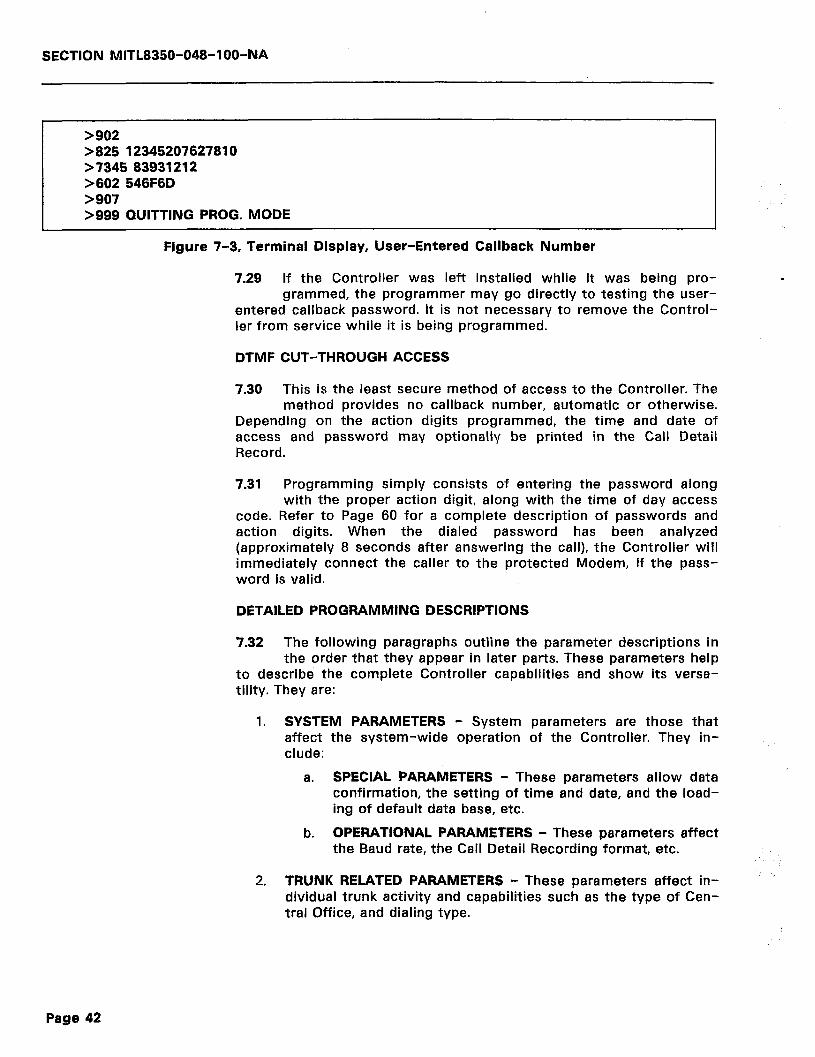
SECTION MITL8350-048-l OO-NA
>902 >825 12345207627810 >7345 83931212 >602 546F6D >907 >999 QUITTING PROG. MODE
Figure 7-3, Terminal Display, User-Entered Callback Number
7.29 If the Controller was left installed while it was being pro- grammed, the programmer may go directly to testing the user-
entered callback password. It is not necessary to remove the Control- ler from service while it is being programmed.
_
DTMF CUT-THROUGH ACCESS
7.30 This is the least secure method of access to the Controller. The method provides no callback number, automatic or otherwise.
Depending on the action digits programmed, the time and date of access and password may optionally be printed in the Call Detail Record.
7.31 Programming simply consists of entering the password along with the proper action digit, along with the time of day access
code. Refer to Page 60 for a complete description of passwords and action digits. When the dialed password has been analyzed (approximately 8 seconds after answering the call), the Controller will immediately connect the caller to the protected Modem, if the pass- word is valid.
DETAILED PROGRAMMING DESCRIPTIONS
7.32 The following paragraphs outline the parameter descriptions in the order that they appear in later parts. These parameters help
to describe the complete Controller capabilities and show its versa- tility. They are:
1. SYSTEM PARAMETERS - System parameters are those that affect the system-wide operation of the Controller. They in- clude:
a. SPECIAL PARAMETERS - These parameters allow data confirmation, the setting of time and date, and the load- ing of default data base, etc.
b. OPERATIONAL PARAMETERS - These parameters affect the Baud rate, the Call Detail Recording format, etc.
2. TRUNK RELATED PARAMETERS - These parameters affect in- dividual trunk activity and capabilities such as the type of Cen- tral Office, and dialing type.
Page 42

SECTION MlTL8350-048-I OO-NA
3. PASSWORD PROGRAMMING - This part includes the program- ming of the password itself. It also describes the accompanying codes that will control whether or not the password is printed in the Call Detail Record, the time of day that the password will be accepted, and the action to perform upon acceptance of the password. Programming is required in this area for either auto- matic callback operation, user-entered callback numbers, or cut through access.
4. AUTOMATIC CALLBACK PROGRAMMING (SPEEDCALLS) - This programs the area where the numbers to be dialed out for an automatic callback triggered by the password are stored. This area includes the programming of a selected ‘route’, if desired. For other modes of operation, no programming is required in this area.
5. SEARCH TABLES - Callback numbers are normally passed through the ‘Search Tables’ in order to decide which ‘route’ the callback will be placed on. If the standard DDD route is used for callbacks (no ‘Other Common Carrier’ used), it will probably not be necessary to program these parameters. The default entries will handle most cases, whether the calls are long distance or local.
This area, if programmed properly, could be used to prevent callbacks to certain geographical areas or to prevent any long distance calls whatsoever, or to determine what types of dial out will be allowed in general (user-entered in particular). Both automatic and user-entered callback numbers may pass through these search tables prior to the controller dialing. An instruction to deny calls to a particular area code at this point would not allow the call to that area code even if it were entered in the Automatic Callback Programming data.
6. ROUTE RELATED PARAMETERS - Routes, as defined for the Controller, are dialing sequences, control of dialtone detection, the sequence of digits to be dialed out, and other related de- tails. A route is actually better defined as the instructions that the Controller uses in accomplishing the callback function.
The default programming that is resident in the Controller will place all callbacks on the DDD Route (normal dialing through ATT or whatever standard service is being used). In the event that a customer is using an ‘Other Common Carrier (OCC)’ such as SPRINT, MCI, etc., these ‘routes’ may be programmed contain the information for automatic entry of the authorization codes, etc.
System Parameters
7.33 Table 7-2 on the next page contains System Special Parameters while Table 7-3 (page 47) contains System Operational Param-
eters. These parameters include default, if applicable, and a description of the options available when entering the parameters.
Page 43

SECTION MITL8350-048-IOO-NA
Table 7-2, System Special Parameters -
ENTER DESCRIPTION
x, x, 999 Exit program mode.
980mmddhhmm Enter Date and Time for Call Detail Record and Time-of-Day Access Control.
902 Enter Data Confirmation Mode. This parameter allows pro- grammed data to be read back for verification.
907
942903
Exit Data Confirmation Mode. Return to program mode.
Load Factory Installed Default Database. This command will re-install all default database parameter settings and will de- lete any other programmed data.
942904 Delete All Search Table Entries. CAUTION - This command deletes all callback instructions that are resident in the 801 through 815 and 821 through 835 Search Tables. The Con- troller cannot operate without data entered in these tables. The only reason for erasing this data is if the user wishes to restart with an entirely new data program and where it is not convenient to delete the old data one piece at a time.
601 ( Number) BB Area Code of Other Common Carrier (if used). The default for this entry is ‘000’. The entry must always be 3 digits, if used.
602 (ASCII ) BB Machine Identifier for Call Detail Recording Output. The de- fault for this entry is ‘SAC’. A maximum of three characters will be printed.
604 {ASCII ) BB Terminal Program Security Code. The default for this entry is ‘<CR>’ where <CR> = Carriage Return. A maximum of ‘I5 characters may be used for the entry.
7.34 X, x, 999 - Exit program mode. These commands may be used to exit from a programming session. Either the ‘X’ or ‘x’ com-
mand may be used anywhere in string entry to cause the Controller to immediately exit from the programming mode. The ‘999’ command is only used to exit from a programming session when all programming has been completed. The terminal display will reply with the message:
1
> 19991 QUITTING PROG. MODE
Note: If X’ or ‘x’ are used to exit programming, the message will be printed, but the [9991 entry in the example above will be either [XI or [xl respectively. In the example above and in the exam- ples to follow, user entered data is enclosed in the brackets [ 1. All other data not enclosed in the brackets is data that the Controller sends to the terminal display.
7.35 The Controller, after sending the message to the display, exits programming mode. To re-enter the programming mode, the
user must type a <CR> on the terminal keyboard.
Page 44
SECTION MITL8350-048-l OO-NA
., :.:_,. i,.
7.36 980 - Enter Date and Time for Call Detail Record and Time- of-Day Access Control. This command must be followed by the
two digit groups for the current month, day, hour, and minutes (format mmddhhmm). The command sets the internal clock of the Controller. This internal clock is used for the time printout on the Call Detail Record. It is also used to determine if access is allowed due to the time-of-day programming by comparing the actual time of call against the preprogrammed time-of-day parameter.
7.37 A typical entry for a ‘980’ parameter for January 28, 09:26 AM would be:
> [980012809261 >
7.38 902 - Enter Data Confirmation Mode. This command causes the controller to leave the programming mode and enter the data
confirmation mode. This mode allows the programmer to verify that the Controller has received the programming data correctly into the internal memory. Once entered, the command causes the Controller to return the > prompt to the display. The Controller then expects the programmer to enter a parameter to be checked. Once entered, the controller will space on the display and show the characteristics of that particular parameter. For example, if a check were made of the machine identifier as entered in paragraph 7.06, the following steps would be accomplished:
> 19021 > 16021 546F6D > [9071 >
Note: 9xX parameters are commands and therefore, not verifiable.
7.39 907 - Exit Data Confirmation Mode. The ‘907’ command causes the Controller to exit from a data confirmation session and to
return to the programming mode. A typical example of this is shown above where the ‘602’ parameter was checked for accuracy.
7.40 942903 - Load Factory Installed Default Database. This com- mand should be used with caution. It will cause the Controller
to delete all previous programming data and to install all default database parameter settings. In Tables that follow, these default pa- rameter settings are listed in column 2. The example below shows the manner of entry.
> [9421 > [9031 >
7.41 942904 - Delete All Search Table Entries. This is another com- mand that should be used with extreme caution. It causes the
Controller to delete all data that has been entered in the 801 through
Page 45
SECTION MITL8350-048-l OO-NA
815 and 821 through 835 Search Tables. If only a few entries in these tables are to be changed, it is recommended that the parameters to be changed be programmed singularly. This command should only be used if there are too many parameters to be changed one at a time and it is desired to re-enter the complete programming for all the Search Tables. Note that the Controller cannot function properly with- out data in these tables.
Note:
> > >
After deleting all search table entries with the 942904 com- mand, the default data base can be reloaded by entering a 942903 command.
[9421 [9041
7.42 601 - Area Code of Other Common Carrier (OCC). If the OCC requires an area code entry for dialing, it should be entered
with this command. Command data entry should be followed with the end of entry indicators ‘BB’. The data to be entered must be 3 digits in length, if used. If not used, the default data for this entry is ‘000’. For example, if the area code for the OCC was ‘613’, it would be entered as follows:
> [601613BBl >
7.43 602 - Machine Identifier for Call Detail Record Output. This command allows the programmer to enter a character or group
of characters that will be printed on the Call Detail Record. It appears on the far right side of the printout. Note that only three characters will be printed, regardless of the length of the identifier over three characters. If the identifier is under four characters, all will be printed. The identifier must be entered as ASCII characters. Refer to Appendix C, Table C-l for ASCII equivalents. The command data must be termi- nated with the ‘BB’ terminator. The default for this command is ‘SAC’. For example, if the Controller is to be identified as ‘CHICAGO’ (only ‘CHI’ will appear in CDR output), it would be programmed as:
> [6024348494341474FBBl >
7.44 604 - Terminal Program Security Code. This command allows _ the programmer to change the security code required for entry
into programming. The security code default on initialization is ‘<CR>‘. Once initialized, the unit enters immediately into the programming mode if the security code has not been changed. The data for this entry is limited to 15 characters maximum and must be entered in ASCII format. The data string entered must be followed by the ‘BB’ data entry terminator. Refer to Appendix C, Table C-l for the ASCII equiv- alents. For example, if a programmer wished to change the security code to ‘BOB’, the entry would appear as:
Page 46
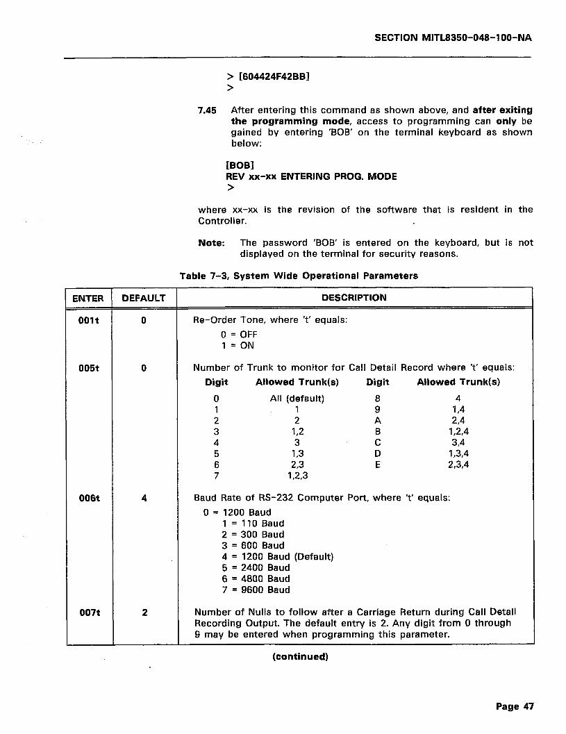
SECTION MlTL8350-048-l OO-NA
> [604424F42BBl >
7.45 After entering this command as shown above, and after exiting the programming mode, access to programming can only be gained by entering ‘BOB’ on the terminal keyboard as shown below:
[BOB] REV xx-xx ENTERING PROG. MODE >
where xx-xx is the revision of the software that is resident in the Controller.
Note: The password ‘BOB’ is entered on the keyboard, but is not displayed on the terminal for security reasons.
Table 7-3, System Wide Operational Parameters
NTER DEFAULT DESCRIPTION
Dolt 0 Re-Order Tone, where ‘t’ equals:
0 = OFF 1 = ON
D05t 0 Number of Trunk to monitor for Call Detail Record where ‘t’ equals:
Digit Allowed Trunk(s) Digit Allowed Trunk(s)
0 All (default) 8 4 1 1 9 I,4 2 2 A 24 3 I,2 B I ,2,4 4 3 C 3,4 5 I,3 D 1,3,4 6 23 E 234 7 123
006t 4 Baud Rate of RS-232 Computer Port, where ‘t’ equals:
0 = 1200 Baud 1 = 110 Baud 2 = 300 Baud 3 = 600 Baud 4 = 1200 Baud (Default) 5 = 2400 Baud 6 = 4800 Baud 7 = 9600 Baud
007t 2 Number of Nulls to follow after a Carriage Return during Call Detail Recording Output. The default entry is 2. Any digit from 0 through 9 may be entered when programming this parameter.
(continued)
Page 47
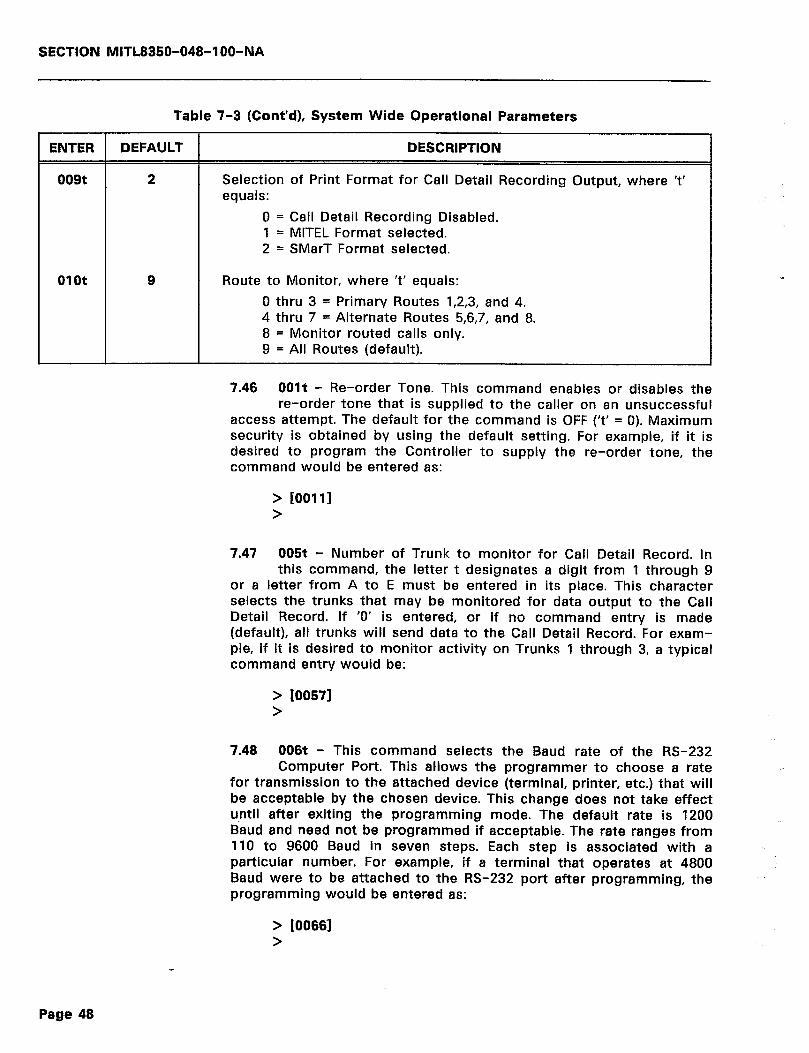
SECTION MITL8350-048-IOO-NA
Table 7-3 (Cont’d), System Wide Operational Parameters
ENTER DEFAULT DESCRIPTION
009t 2 Selection of Print Format for Call Detail Recording Output, where ‘t’ equals:
0 = Call Detail Recording Disabled. 1 = MITEL Format selected. 2 = SMarT Format selected.
01ot 9 Route to Monitor, where ‘t’ equals:
0 thru 3 = Primary Routes 1,2,3, and 4. 4 thru 7 = Alternate Routes 5,6,7, and 8. 8 = Monitor routed calls only. 9 = All Routes (default).
7.46 OOlt - Re-order Tone. This command enables or disables the re-order tone that is supplied to the caller on an unsuccessful
access attempt. The default for the command is OFF (‘t’ = 0). Maximum security is obtained by using the default setting. For example, if it is desired to program the Controller to supply the re-order tone, the command would be entered as:
> [00111 >
7.47 005t - Number of Trunk to monitor for Call Detail Record. In this command, the letter t designates a digit from 1 through 9
or a letter from A to E must be entered in its place. This character selects the trunks that may be monitored for data output to the Call Detail Record. If ‘0’ is entered, or if no command entry is made (default), all trunks will send data to the Call Detail Record. For exam- ple, if It is desired to monitor activity on Trunks 1 through 3, a typical command entry would be:
> 100571 >
7.48 006t - This command selects the Baud rate of the RS-232 Computer Port. This allows the programmer to choose a rate
for transmission to the attached device (terminal, printer, etc.) that will be acceptable by the chosen device. This change does not take effect until after exiting the programming mode. The default rate is 1200 Baud and need not be programmed if acceptable. The rate ranges from 110 to 9600 Baud in seven steps. Each step is associated with a particular number. For example, if a terminal that operates at 4800 Baud were to be attached to the RS-232 port after programming, the programming would be entered as:
> [00661 >
Page 48
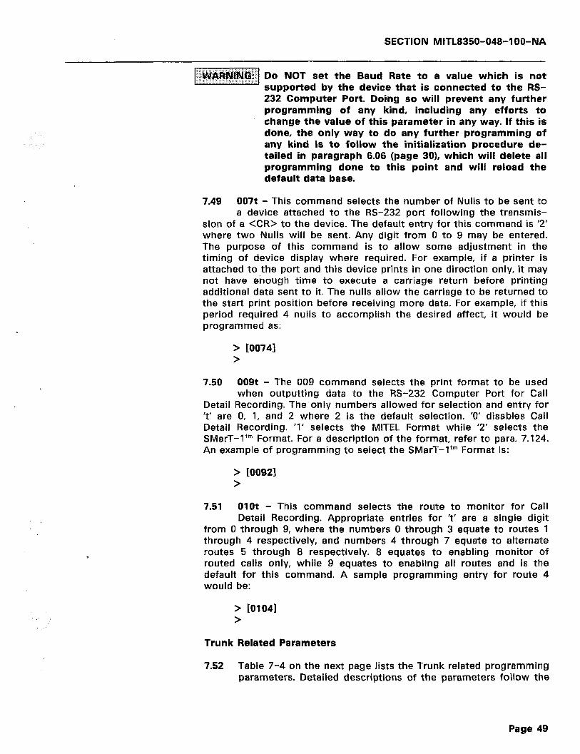
SECTION MITL8350-048-1 OB-NA
=:-_11 ‘I’l”~~~ii~~~~‘~ ~0 NOT set the Baud Rate to a value which is not
supported by the device that is connected to the RS- 232 Computer Port. Doing so will prevent any further programming of any kind, including any efforts to change the value of this parameter in any way. If this is done, the only way to do any further programming of any kind is to follow the initialization procedure de- tailed in paragraph 6.06 (page 301, which will delete all programming done to this point and will reload the default data base.
7.49 007t - This command selects the number of Nulls to be sent to a device attached to the RS-232 port following the transmis-
sion of a <CR> to the device. The default entry for this command is ‘2’ where two Nulls will be sent. Any digit from 0 to 9 may be entered. The purpose of this command is to allow some adjustment in the timing of device display where required. For example, if a printer is attached to the port and this device prints in one direction only, it may not have enough time to execute a carriage return before printing additional data sent to it. The nulls allow the carriage to be returned to the start print position before receiving more data. For example, if this period required 4 nulls to accomplish the desired affect, it would be programmed as:
> 200741 >
7.50 009t - The 009 command selects the print format to be used when outputting data to the RS-232 Computer Port for Call
Detail Recording. The only numbers allowed for selection and entry for ‘t’ are 0, 1, and 2 where 2 is the default selection. ‘0’ disables Call Detail Recording. ‘1’ selects the MITEL Format while ‘2’ selects the SMarT-1’” Format. For a description of the format, refer to para. 7.124. An example of programming to select the SMarT-1’” Format is:
> [00921 >
7.51 01ot - This command selects the route to monitor for Call Detail Recording. Appropriate entries for ‘t’ are a single digit
from 0 through 9, where the numbers 0 through 3 equate to routes 1 through 4 respectively, and numbers 4 through 7 equate to alternate routes 5 through 8 respectively. 8 equates to enabling monitor of routed calls only, while 9 equates to enabling all routes and is the default for this command. A sample programming entry for route 4 would be:
> jo1041 >
Trunk Related Parameters
7.52 Table 7-4 on the next page lists the Trunk related programming parameters. Detailed descriptions of the parameters follow the
Page 49
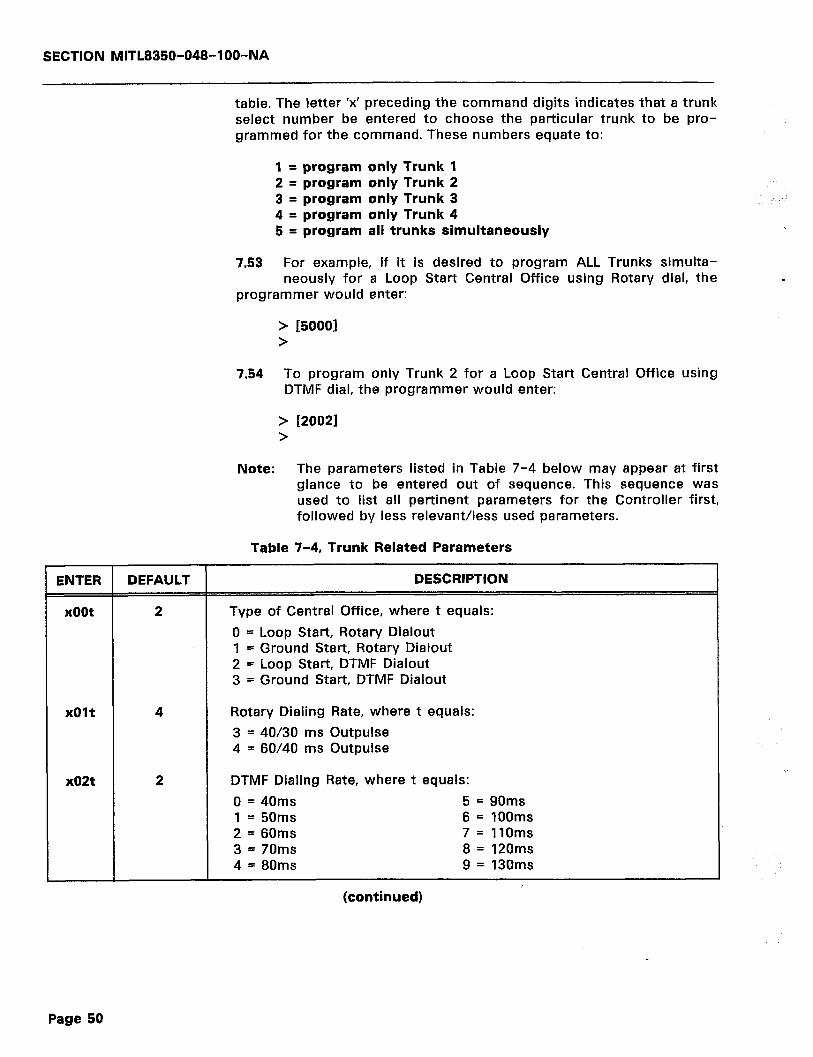
SECTION MITL8350-048-l OO-NA
table. The letter ‘x’ preceding the command digits indicates that a trunk select number be entered to choose the particular trunk to be pro- grammed for the command. These numbers equate to:
1 = program only Trunk 1 2 = program only Trunk 2 3 = program only Trunk 3 4 = program only Trunk 4 5 = program all trunks simultaneously
7.53 For example, if it is desired to program ALL Trunks simulta- neously for a Loop Start Central Office using Rotary dial, the
programmer would enter:
> [50001 >
7.54 To program only Trunk 2 for a Loop Start Central Office using DTMF dial, the programmer would enter:
> >
Note:
[20021
The parameters listed in Table 7-4 below may appear at first glance to be entered out of sequence. This sequence was used to list all pertinent parameters for the Controller first, followed by less relevant/less used parameters.
Table 7-4, Trunk Related Parameters
ENTER DEFAULT DESCRIPTION
xoot 2 Type of Central Office, where t equals:
0 = Loop Start, Rotary Dialout 1 = Ground Start, Rotary Dialout 2 = Loop Start, DTMF Dialout 3 = Ground Start, DTMF Dialout
xOlt 4 Rotary Dialing Rate, where t equals:
3 = 40/30 ms Outpulse 4 = 60/40 ms Outpulse
x02t 2 DTMF Dialing Rate, where t equals:
0 = 40ms 5 = 90ms 1 = 50ms 6 = 100ms 2 = 60ms 7= 1lOms 3 = 70ms 8 = 120ms 4 = 80ms 9 = 130ms
I (continued)
Page 50

SECTION MITL8350-048-1 OO-NA
Table 7-4 (Cont’d), Trunk Related Parameters
ENTER DEFAULT DESCRIPTION
x05t 5 Time period between Line Drop and Reseizure, where t equals:
0 = 500ms 5 = 1250ms 1 = 650ms 6 = 1400ms 2 = 800ms 7 = 1550ms 3 = 950ms 8 = 1700ms 4 = 1100ms 9 = 1850ms
x27t 1 Call Answer Timer, where if t = 0, The Controller is ‘OFF’ and all SAC activity is disabled. Calls into the protected Modem will not be processed or interfered with. Other values for t are:
1 = 3 seconds 9 = 27 seconds 2 = 6 seconds A = 30 seconds 3 = 9 seconds B = 33 seconds 4 = 12 seconds C = 36 seconds 5 = 15 seconds D = 39 seconds 6 = 18 seconds E = 42 seconds 7 = 21 seconds F = 45 seconds 8 = 24 seconds
x28t 1 Wait for Password Timer (after Answer), and Wait for User-Entered Callback Number (if called for in the password action digits). The first entry for t below is for the Password Timer, while the second entry is for the User-Entered Callback Number (if used). t equals:
0 = 4/8 seconds 1 = 8/16 seconds 2= 12/24 seconds 3 = 16/32 seconds 4 = 20/40 seconds 5 = 24/48 seconds 6 = 28/56 seconds 7 = 32/64 seconds
8 = 36/72 seconds 9 = 40/80 seconds A = 44/88 seconds B = 48/96 seconds C = 52/104 seconds D = 56/112 seconds E = 60/120 seconds
x29t 2 Lockout Timer. This timer will be invoked at the end of x28t if either no password has been entered, or if an invalid password has been entered. The timer will ‘busy out’ the affected trunk for the duration of the its time period, preventing multiple rapid succes- sion access attempts by unauthorized callers. Values for t are:
0 = 10 seconds 8 = 90 seconds 1 = 20 seconds 9 = 100 seconds 2 = 30 ,seconds A = 110 seconds 3 = 40 seconds B = 120 seconds 4 = 50 seconds C = 130 seconds 5 = 60 seconds D = 140 seconds 6 = 70 seconds E = 150 seconds 7 = 80 seconds F = 160 seconds
(continued)
Page 51

SECTION MITL8350-048-l OO-NA
Table 7-4 (Cont’d), Trunk Related Parameters
ENTER DEFAULT DESCRIPTION
x35t 0 Progress Tones (Beeps), where t equals:
Request Request t Password Callback Nr.
(1 Tone) (2 Tones)
0 ON ON . 1 ON ON 2 ON OFF 3 ON OFF 4 OFF ON 5 OFF ON 6 OFF OFF 7 OFF OFF
Hang UP
(3 Tones)
ON OFF ON OFF ON OFF ON OFF
x36t 1 Time to wait after valid password determination before processing of the callback (drop and reseize parameter x05t) is initiated, where t equals:
0 = Callback Immediately 8 = 80 seconds 1 = 10 seconds ‘9 = 90 seconds 2 = 20 seconds A = 100 seconds 3 = 30 seconds B = 110 seconds 4 = 40 seconds C = 120 seconds 5 = 50 seconds D = 130 seconds 6 = 60 seconds E = 140 seconds 7 = 70 seconds . F = 150 seconds
7.55 xoot - This command configures the Controller for the type of Central Office that will be connected to the line. These types
are either Loop Start or Ground Start. The command also selects the type of dialing to be used to access the Central Office when executing a callback sequence. The two types of dialing are either Rotary or DTMF dialout. The two selections are combined into one command allowing the programmer to select one of the four combinations listed in Table 7-4 above. If no command is programmed, the default selec- tion of Loop Start, DTMF dialout will be in the Controller. For example, if the Controller were to be programmed for a Ground Start CO and to use DTMF dialout on Trunk 1, the command would be:
. > DO031 >
7.56 xOlt - This command will select the Rotary Dialing rate if command xOOt above were programmed for Rotary dialout.
There are two options that are selectable. These are 40 ms Make/30 ms Break or 60 ms Make/40 ms Break. The latter selection is the default for the command and need not be programmed, if required. For example, if all trunks were to use the 40/30 ms Rotary Dialing Rate, the command would be entered as:
Page 52
SECTION MlTL8350-048-lOO-NA
> r50131 >
7.57 x02t - This command will select the DTMF Dialing rate if com- mand xOOt above were programmed for DTMF dialout. The rate
ranges from 40 to 130 ms in 10 ms steps. 60 ms is the default selection for this command. Selection is done by entering a number from 0 through 9 for the letter t in the command line. For example, if Trunk 3 were to use DTMF dialing at a rate of 100 ms, the command would be entered as:
> t30261 >
7.58 x05t - This command programs the time period length between the point where the Controller drops the line and reseizes the
line for a callback execution. The default for this command is 1250 ms. The period length is selectable from 500 to 1850 ms in 150 ms steps. These periods equate to a number from 0 to 9 to be used to replace the letter ‘t’ in the command line. For example, if a period of 1700 ms were required between drop and reseizure on Trunk 1 for the Control- ler, the command would be entered as:
> DO581 >
7.59 x27t - The x27t command programs the Call Answer Timer to wait for a period of time after detecting the first ring on the
line, before answering the call. The default period of time is 3 seconds (i.e., after detecting ringing, the Controller will wait for 3 seconds before answering the call). The period selection ranges from 3 to 45 seconds in 3 second steps. These are designated by a number from 1 to 9, or a letter from A to F to replace the ‘t’ in the command. For example, if all trunks were to be programmed to wait for 6 seconds after ringing detection before answering, the command would be en- tered as:
> 152721 >
7.60 x28t - This command performs two functions, if required. The first and most important is to wait for the password to be
received. The second is to wait for a user entered callback number to be received (if called for in the password action digits). The command will cause the controller to perform the first wait period. If the pass- word action digits indicate that a user entered callback number is to be received, the second wait period after entry of the password will be accomplished. For more information on the password action digits, refer to password programming on page 60. The wait period for the wait for password timer is programmable from 4 to 60 seconds in 4 second steps. These steps equate to the number from 0 to 9 or the letter from A to E to be used in place of ‘t’. The second timer is programmed automatically from the selection of the first timer. The second timer will always be (if used) two times the period of the first
Page 53

SECTION MITL8350-048-l OO-NA
timer. The default for this command is 8/16 seconds (i.e., the Controller will wait for 8 seconds for the caller to enter a valid password before timing out and terminating the call and 16 seconds for the caller to enter his callback number (if used). For example, if it is desired to have the Controller to wait 16 seconds for password entry by the caller on Trunk 2, the command would be entered as:
> 122831 >
7.61 The entry of the period for waiting
7.62 x29t - The x29t Timer. This timer
.I .:
above command assumes that, if used, the for callback number entry will be 32 seconds. *
command is used to program the Lockout will start if, at the end of the x28t wait for
password period expires and if either an invalid password, or no pass- word has been received. During the period that this timer is in effect, the Controller will ‘busy out’ the affected trunk(s) for the period. This prevents multiple rapid succession access attempts by unauthorized users. The default period for this timer is 20 seconds. The period is programmable from 10 to 160 seconds in 10 second steps. To select a period, enter a number from 0 to 9 or a letter from A to F in place of ‘t’. For example, if minimum lockout is desired on Trunk 1 and 30 seconds of lockout were desired on Trunk 3, the commands would be entered as:
> [12901 > r32921 >
7.63 This parameter should be set equal to or greater than the length of time that the Modem waits for Answer Tone. In addi-
tion, the SAC monitors for Modem loop current, and, if this timer should expire while the Modem is still on line, the presence of the Modem line state will continue to hold the ‘busy out’ state. The ‘busy out’ in this instance, will cease when the Modem goes off line.
7.64 x35t - This command programs the use of progress tones to be sent back to the caller to indicate dialing progress. If ‘7’ is
entered into the command line for ‘t’, all progress tones are disabled. The default for this command is ‘0’ or all progress tones on. If ‘0’ is entered, the caller will receive a single progress tone (1 beep) request- ing entry of password, a double progress tone (2 beeps) to request entry of user entered callback number, and a triple progress tone (3 beeps) to request the caller to hang up for callback. For example, if all trunks were to be programmed for a single progress tone to indicate password entry, the command line would be typed as:
> 153531 >
7.65 x36t - The x36t command programs the amount of time to wait after valid password determination before initiating the callback
process (i.e., time until initiation of the drop and reseize command
Page 54
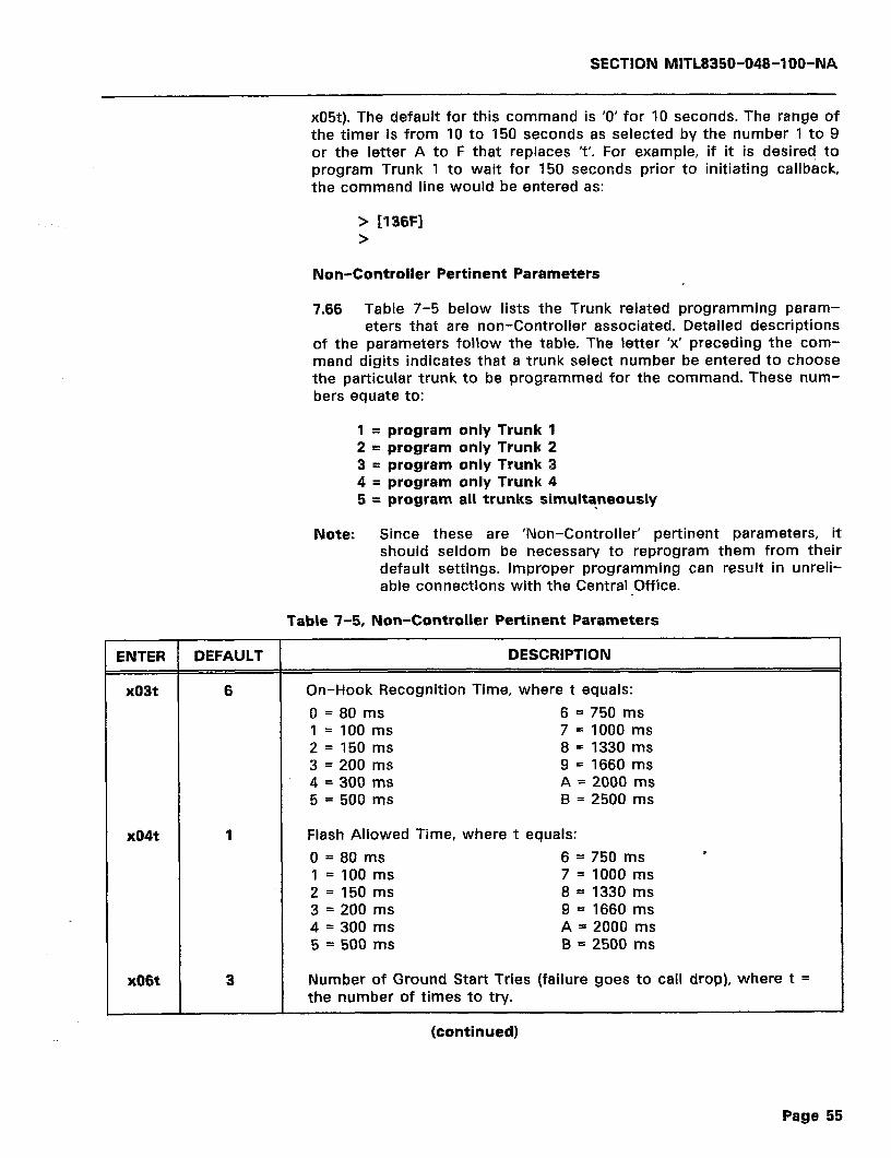
SECTION MlTL8350-048-lOO-NA
x05t). The default for this command is ‘0’ for 10 seconds. The range of the timer is from 10 to 150 seconds as selected by the number 1 to 9 or the letter A to F that replaces ‘t’. For example, if it is desired to program Trunk 1 to wait for 150 seconds prior to initiating callback, the command line would be entered as:
> Il36Fl >
Non-Controller Pertinent Parameters
7.66 Table 7-5 below lists the Trunk related programming param- eters that are non-Controller associated. Detailed descriptions
of the parameters follow the table. The letter ‘x’ preceding the com- mand digits indicates that a trunk select number be entered to choose the particular trunk to be programmed for the command. These num- bers equate to:
1 = program only Trunk 1 2 = program only Trunk 2 3 = program only Trunk 3 4 = program only Trunk 4 5 = program all trunks simultaneously
Note: Since these are ‘Non-Controller’ pertinent parameters, it should seldom be necessary to reprogram them from their default settings. Improper programming can result in unreli- able connections with the Central Office.
Table 7-5, Non-Controller Pertinent Parameters
ENTER DEFAULT DESCRIPTION
x03t 6 On-Hook Recognition Time, where t equals:
0 = 80 ms 6 = 750 ms 1 = 100 ms 7 = 1000 ms 2 = 150 ms 8 = 1330 ms 3 = 200 ms g = 1660 ms 4 = 300 ms A = 2000 ms 5 = 500 ms B = 2500 ms
x04t 1 Flash Allowed Time, where t equals:
0 = 80 ms 6 = 750 ms ’ 1 = 100 ms 7 = 1000 ms 2 = 150 ms 8 = 1330 ms 3 = 200 ms 9 = 1660 ms 4 = 300 ms A = 2000 ms 5 = 500 ms B = 2500 ms
x06t 3 Number of Ground Start Tries (failure goes to call drop), where t = the number of times to try.
(continued)
Page 55

SECTIQN MITL8350-048-IOO-NA
Table 7-5, Non-Controller Pertinent Parameters
ENTER DEFAULT DESCRIPTION
x07t 3 Time to wait for Tip Ground on Ground Start Try (Ground Start Timeout in seconds), where t equals number of seconds to wait until timeout.
x14t 4 Rotary Inter-digit Pause for Central Office (outgoing dialing), where t equals: 0 = 400 ms 5 = 900 ms 1 = 500 ms 6 = 1 second 2 = 600 ms 7 = 1.1 seconds 3 = 700 ms 8 = 1.2 seconds 4 = 800 ms
xzot 2 Incoming Ringing Sensitivity, where t nominally equals: 0 = 40 ms 8 = 140 ms 1 = 50 ms 9 = 160 ms 2 = 60 ms A = 170 ms 3 = 80 ms B = 180 ms 4 = 90 ms C = 200 ms 5 = 100 ms D = 210 ms 6 = 120 ms E = 220 ms 7 = 130 ms F = 240 ms .
x21t 6 Inter-ring timing in seconds, where t equals the number of sec- onds to wait.
x24t
x31t
Select Default Route for use within one of two groups of four routes. If this command is set to either 0, 1, 2, or 3, the primary routes will be used. If it is set to either 4, 5, 6, or 7, the alternate routes will be used. ‘Use Default Route’ is an action digit that is included within the 801 through 815 Search Table action digits (for more information, refer to page 65 paragraph 7.106). ‘t’ equals:
0 = Use Primary Routes 0 through 3 4 = Use Alternate Routes 4 through 7
Tip Ground Application Timer, where t equals:
0=40ms 6 = 240 ms 1 =40 ms 7 = 280 ms 2 = 80 ms 8 = 320 ms 3 = 120 ms 9 = 360 ms 4 = 160 ms A = 400 ms 5 = 200 ms B = 440 ms
x33t 0 Flit Timing, where t equals:
0 = 40 ms 8 = 20 ms
(continued)
Page 56 i

SECTION MITL8350-048-l OO-NA
ENTER DEFAULT 1
x34t
Table 7-5 (Cont’d), Non-Controller Pertinent Parameters
DESCRIPTION
6 Tip Ground Removal Timer, where t equals:
0 = 40 ms 6 = 240 ms 1 = 40 ms 7 = 280 ms 2 = 80 ms 8 = 320 ms 3 = 120 ms 9 = 360 ms 4 = 160 ms A = 400 ms 5 = 200 ms B = 440 ms
7.67 x03t - This command programs the On-Hook Timing (i.e., how long the controller has to recognize an on-hook condition). The
default for the command is 750 ms. The parameter can be pro- grammed for a period from 80 to 2500 ms in 12 steps. To select a particular timing, enter a number from 0 to 9 or the letter A or B in place of ‘t’ in the command line. For example, if it is desired to program all trunks for an On-Hook Recognition Time of 500 ms, the command would be entered as:
> r50351 >
7.68 x04t - The x04t command programs the Flash Allowed Timing. If the Flash Allowed Time is longer than the On-Hook Timing
(x03t), then flash is not allowed. The default for the command is 80 ms. The time period can be programmed from 80 to 2500 ms in 12 steps. To select a particular timing, enter a number from 0 to 9, or the letter A or B in place of ‘t’ in the command line. For example, if it is desired to program all trunks for a Flash Allowed Time of 1000 ms, the com- mand would be entered as:
> [50473 >
7.69 x06t - This command programs the Controller for the number of Ground Start Tries in case of failure. A failure after the
indicated number of tries will go to a call drop. The default for this command is 3. ‘t’ is selected as the number of tries where ‘t’ equates to the digit 0 through 9. If Trunk 1 were allowed 4 Ground Start tries, the command would be entered as:
> [lo641 >
7.70 x07t - The x07t command programs the Controller for the time period to wait for Tip Ground to appear on the line on a Ground
Start try. The default for this command is 3 seconds. ‘t’ equates to the number of seconds and may be a number from 0 to 9. For example, if it is desired to program the Controller for a Ground Start timeout of 6 seconds on Trunk 2, the command would be entered as:
Page 57
SECTION MITL8350-048-l OO-NA
> C20761 >
7.71 x14t - The x14t command programs the Rotary Dial Inter-Digit Pause time for the Central Office on outgoing dialing. The de-
fault for this command is 800 ms. The time period is programmable from 400 to 1200 ms in 100 ms steps. A period is selected by replacing the ‘t’ in the command line with a number from 0 through 8. For example, if it is desired to program the Controller for an Inter-digit Pause time of 1200 ms on Trunk 3, the command would appear as:
> [31481 >
7.72 x20t -This command programs the Incoming Ringing Sensitiv- ity. This sensitivity indicates a time period from the initial ap-
plication of ringing to the line, to the first recognition of ringing by the Controller. These times are nominal and may be slightly different when actually measured. The period can range from 40 to 240 ms in 16 steps and is selected by substituting a number from 0 to 9, or a letter from A to F for ‘t’ in the command line. For example, if Trunk 2 were to be programmed for a ringing sensitivity of 160 ms, the command would be entered as:
> 122091 >
7.73 x21t - This command programs the Inter-Ring Timing in sec- onds. The period may range from 0 to 9 as selected by sub-
stituting a number from 0 to 9 respectively for ‘t’ in the command line. The default for the command is 6 seconds. For example, if it were desired to program all trunks for an 8 second Inter-Ring time period, the command would be entered as:
> [52181 >
7.74 x24t - The x24t command programs the Controller to Select Default Route when called for as an action digit in the Search
Tables. This route is from within one of two groups of four routes. Routes are either primary or alternate and are numbered from 1 to 4 for the primary; from 5 to 8 for the alternate. Since one of these two groups is to be selected by this command, it is only necessary to enter a ‘0’ (primary) or a ‘4’ (alternate) in place of ‘t’ in the command line. Any other number from 0 to 3 will also select primary routes, and any other number from 4 to 7 will select alternate routes. If the ‘Use Default Route’ is desired, it must be programmed as an action digit in the 801 through 815 Search Tables. The default for the command is ‘0’ or use primary routes 1 through 4. An example of programming Trunk 2 to use alternate routes 4 through 7 would be entered as:
> 122441 >
Page 58
SECTION MlTL8350-048-l OO-NA
7.75 x31t - This command programs the Tip Ground Application Timer for Tip Ground application recognition (GND START). The
time period is selectable from 40 to 440 ms in 12 steps. The period is selected by substituting a number from 0 to 9, or the letter A or B that equates to the desired time period. The default for the command is 120 ms or ‘3’. For example, to program all trunks for a Tip Ground Applica- tion Timer of 440 ms, the command would be entered as:
> [531Bl >
7.76 x33t - This parameter controls the hit timing for the trunk. Hit timing is the minimum time that an on-hook, a line break, or a
D C short must appear on the trunk before the nize it. To change the Hit Timing to 20 ms, enter:
Controller will recog-
> [23381 >
7.77 x34t - The x34t command programs the Controller for the lip Ground Removal Timer. A period within the range of 0 to 440
ms can be selected by substituting a number from 0 to 9, or the letter A or B for ‘t’ in the command line. These periods are listed in Table 7-5 above under the x34t command. The default for the command is 240 ms. For example, to program all trunks for a 120 ms Tip Ground Removal time, the command would be entered as:
> c53431 >
PASSWORD PROGRAMMING
7.78 Passwords can range from 2 to 15 digits in length, depending upon the desired usage. Refer to Figure 7-4 for an illustration of
the password format. Password programming is accomplished by en- tering a password string in the 821 through 835 Search Tables.
7.79 If the Controller is intended to provide an automatic callback function, the password can only range in length from 3 to 12
digits. The last three digits are used as the Speed Call Address which is a label that identifies the callback number to use. Therefore, in this case, the password will be from 3 to 15 digits in length.
7.80 If the password action digit does not perform automatic call- back, then the password may be from 1 to 15 digits in length.
There is no need for a label to the speed call bin.
7.81 Note that no two passwords may be identical regardless of the action digits that are associated with it. Entering a second
identical password will overwrite the original password in the list.
Note: When comparing the Password Tables against the dialed in password, the last action encountered will be used. Refer to the password programming examples in later text.
Page 59
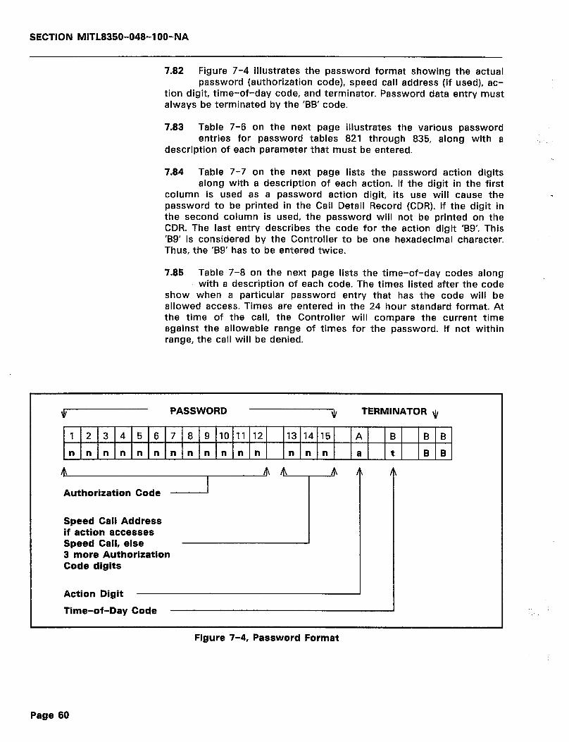
SECTION MITL8350-048-IOO-NA
7.82 Figure 7-4 illustrates the password format showing the actual password (authorization code), speed call address (if used), ac-
tion digit, time-of-day code, and terminator. Password data entry must always be terminated by the ‘BB’ code.
7.83 Table 7-6 on the next page illustrates the various password entries for password tables 821 through 835, along with a
description of each parameter that must be entered.
7.84 Table 7-7 on the next page lists the password action digits along with a description of each action. If the digit in the first
column is used as a password action digit, its use will cause the password to be printed in the Call Detail Record (CDR). If the digit in the second column is used, the password will not be printed on the CDR. The last entry describes the code for the action digit ‘B9’. This ‘B9’ is considered by the Controller to be one hexadecimal character. Thus, the ‘B9’ has to be entered twice.
.
7.85 Table 7-8 on the next page lists the time-of-day codes along with a description of each code. The times listed after the code
show when a particular password entry that has the code will be allowed access. Times are entered in the 24 hour standard format. At the time of the call, the Controller will compare the current time against the allowable range of times for the password. If not within range, the call will be denied.
3/ PASSWORD JI TERMINATOR \~r
1 2 3 4 5 6 7 8 9 101112 13 14 15 A B B B
nnnnnnnnnnnn n n n a t B B
m Authorization Code
m 4 m
Speed Call Address if action accesses Speed Call, else 3 more Authorization Code digits
Action Digit
Time-of-Day Code
Figure 7-4, Password Format
Page 60
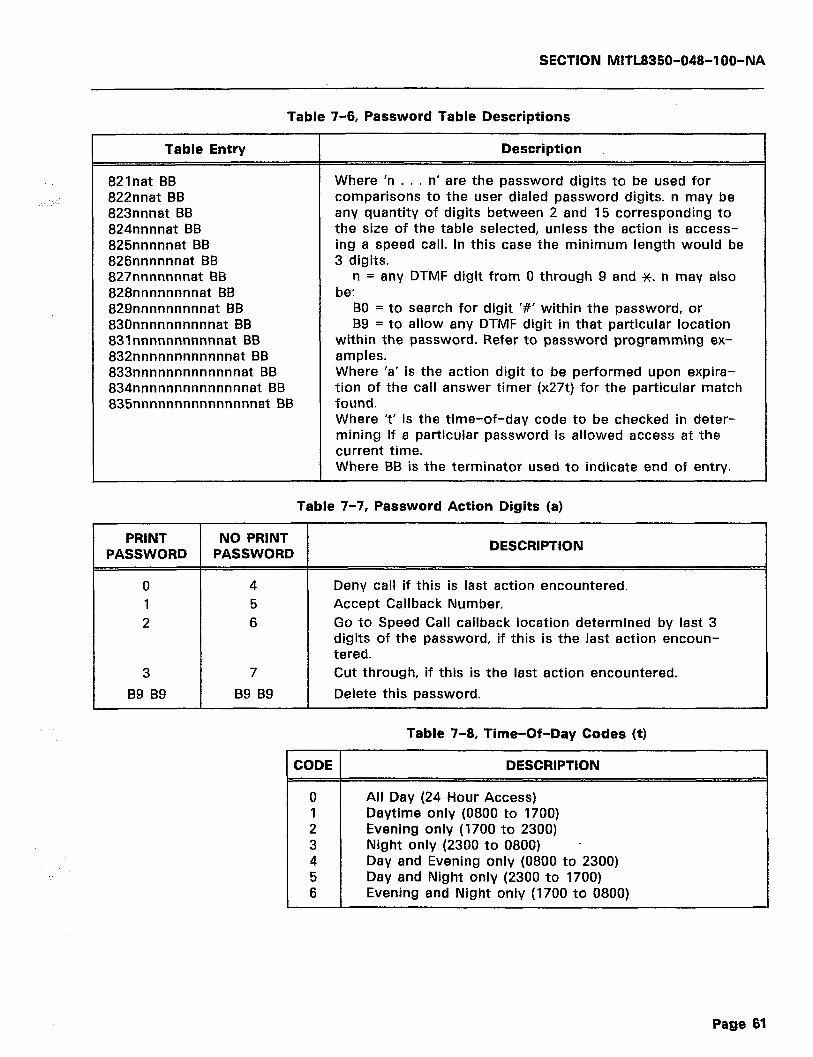
Table Entry
821nat BB 822nnat BB 823nnnat BB 824nnnnat BB 825nnnnnat BB 826nnnnnnat BB 827nnnnnnnat BB 828nnnnnnnnat BB 829nnnnnnnnnat BB 830nnnnnnnnnnat BB 83lnnnnnnnnnnnat BB 832nnnnnnnnnnnnat BB 833nnnnnnnnnnnnnat BB 834nnnnnnnnnnnnnnat BB 835nnnnnnnnnnnnnnnatBB
SECTION MITL8350-048-l OO-NA
Table 7-6, Password Table Descriptions
Description
Where ‘n . . . n’ are the password digits to be used for comparisons to the user dialed password digits. n may be any quantity of digits between 2 and 15 corresponding to the size of the table selected, unless the action is access- ing a speed call. In this case the minimum length would be 3 digits.
n = any DTMF digit from 0 through 9 and JC. n may also be:
BO = to search for digit ‘#’ within the password, or B9 = to allow any DTMF digit in that particular location
within the password. Refer to password programming ex- amples. Where ‘a’ is the action digit to be performed upon expira- tion of the call answer timer (x27t) for the particular match found. Where ‘t’ is the time-of-day code to be checked in deter- mining if a particular password is allowed access at the current time. Where BB is the terminator used to indicate end of entry.
Table 7-7, Password Action Digits (a)
2 6
3 7
B9 B9 B9 B9
DESCRIPTION
Deny call if this is last action encountered. Accept Callback Number. Go to Speed Call callback location determined by last 3 digits of the password, if this is the last action encoun- tered. Cut through, if this is the last action encountered.
Delete this password.
Table 7-8, Time-Of-Day Codes (t)
CODE 1 DESCRIPTION
All Day (24 Hour Access) Daytime only (0800 to 1700) Evening only (1700 to 2300) Night only (2300 to 0800) - Day and Evening only (0800 to 2300) Day and Night only (2300 to 1700) Evening and Night only (1700 to 0800)
Page 61
SECTION MITL8350-048-IOO-NA
Password Programming Examples
7.86 The following paragraphs show examples of password pro- gramming. There are three examples listed. These examples, by
no means include all possible programming methods, but they do illustrate some of the more basic password programming ways.
Example 1
7.87 Example 1 shows a programming line to allow password ‘1111’ to cause an automatic callback without printing the password in
_1
the Call Detail Record. This example allows 24 hour access to the protected Modem. Once in the programming mode, enter:
> [824111160BB] >
7.88 The password is 4 digits in length. Therefore, the ‘824’ param- eter must be used to enter the ‘1111’ in the password tables.
The ‘6’ is the action digit that specifies ‘go to Speed Call callback location ‘111’ (last three digits of password indicate Speed Call bin number) without printing password on CDR’. The ‘0’ is the time-of-day code for all day access (24 hours). ‘BB’ is the data entry terminator.
Example 2
7.89 Example 2 shows a programming line to allow password ‘22222’ to accept a user-entered callback number between 1700 to
2300 hours and to print the password in the Call Detail Record.
> [8252222212BB] >
7.90 The password is 5 digits in length, requiring the use of the ‘825’ parameter for entry in the tables. The ‘1’ is the action digit
specifying accept callback. The ‘2’ is the time-of-day code that speci- fies evening only (1700 - 2300). ‘BB’ is the entry terminator.
Example 3
7.91 Example 3 shows a programming line to allow password ‘9999999999’ to ‘cut through’ (no callback) between 0800 and
1700. The password is also printed in the Call Detail Record.
> [830999999999931 BB] >
7.92 The password is 10 digits in length, requiring the use of the ‘830’ parameter for entry. The ‘3’ is the action digit that speci-
fies cut through. It also specifies that the password be printed in the Call Detail Record. The ‘1’ is the time-of-day code for day only (0800 - 1700). ‘BB’ is the data entry terminator.
Page 62
SECTION MITL8350-048-l OO-NA
7.93 All of these examples may be programmed in one session. This is illustrated in the example below:
> > > > > >
[8241111 SOBS] 18252222212991 [830999999999931BBl [711183931212BB] [9991 QUITTING PROG. MODE
7.94 Note the fourth programming line from the top. This line pro- grams the Speed Call bin number ‘III’ for callback number
‘393-1212’. All Speed Call bins are 7nnn parameters where the 111 indicates the actual stored speed call. This was one of the require- ments in example 1 above. It was required to make the ‘8241111’ entry operational. If no speed call was entered in the ‘I 11 bin, no callback would be accomplished. Refer to paragraph 7.97 below for more in- formation on Speed Calls and Callback Numbers.
7.95 To delete a password, enter the password, followed by the action digits ‘B9B9’. For example:
> [825222221299991 >
will delete the password ‘22222’ and its associated action digits ‘12’ from the ‘825’ (five digit) password table.
AUTOMATIC CALLBACK (SPEED CALL) PROGRAMMING
7.96 The example at the end of this paragraph shows the callback number data entry format where ‘7’ is the register prefix and
‘nnn’ is the ‘bin’ number (address) of the callback number. Bin numbers must be the same as the last three digits of the assigned password that the caller must dial into the Controller. The ‘nnn’ may be any digits from 000 through 999. This allows the use of 1000 callback numbers.
7nnn k mmm . . . mmm BB
7.97 The ‘k’ in the format example above is the network override code. This will normally be an ‘8’ which commands the Control-
ler to use Search Tables 801 through 815. All possible values of ‘k’ are listed in Table 7-9 below.
Table 7-9, Network Override Codes
CODE 1 DESCRIPTION
0 Force callback on Route 1 1 Force callback on Route 2 2 Force callback on Route 3 3 Force callback on Route 4
Page 63
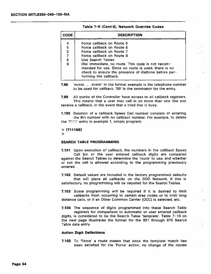
SECTION MlTL8350-048-l OO-NA
Table 7-9 (Cont’d), Network Override Codes
CODE DESCRIPTION
4 Force callback on Route 5 5 Force callback on Route 6 6 Force callback on Route 7 7 Force callback on Route 8 8 Use Search Tables 9 Dial immediate, no route. This code is not recom-
mended for use. Since no route is used, there is no check to ensure the presence of dialtone before per- , forming the callback.
7.98 ‘mmm . . . mmm’ in the format example is the telephone number to be used for callback. ‘BB’ is the terminator for the entry.
7.99 All trunks of the Controller have access to all callback registers. This means that a user may call in on more than one line and
receive a callback, in the event that a tried line is busy.
7.100 Deletion of a callback Speed Call number consists of entering the Bin number with no callback number. For example, to delete
the ‘7111’ entry in example 1, simply program:
> 17111681 >
SEARCH TABLE PROGRAMMING
7.101 Upon execution of callback, the numbers in the callback Speed Call bin or the user entered callback digits are compared
against the Search Tables to determine the ‘route’ to use, and whether or not the call is allowed according to the programming previously entered.
7.102 Default values are included in the factory programmed defaults that will place all callbacks on the DDD Network. If this is
satisfactory, no programming will be required for the Search Tables.
7.103 Some programming will be required if it is desired to limit callbacks from occurring to certain area codes or to limit long
distance calls, or if an Other Common Carrier (OCC) is selected, etc.
7.104 The sequence of digits programmed into these Search Table registers for comparison to automatic or user entered callback
digits, is considered to be the Search Table ‘template’. Table 7-10 on the next page illustrates the format for the 801 through 815 Search Table data entry.
Action Digit Definitions
7.105 To ‘Force’ a route means that once been satisfied for the ‘Force’ action,
the template match has no change of the routes
Page 64
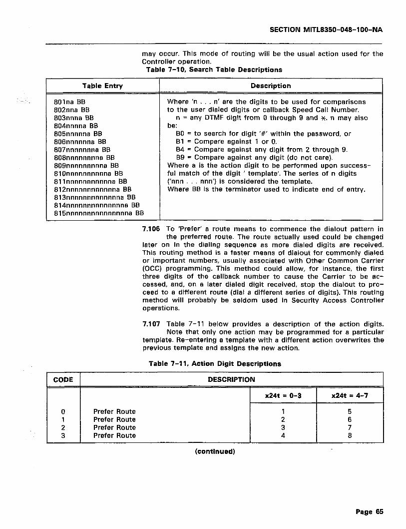
SECTION NliTL8350-048-l OO-NA
may occur. This mode of routing will be the usual action used for the Controller operation.
Table 7-10, Search Table Descriptions
Table Entry Description
801na BB 802nna BB 803nnna BB 804nnnna BB 805nnnnna BB 806nnnnnna BB 807nnnnnnna BB 808nnnnnnnna BB 809nnnnnnnnna BB 8lOnnnnnnnnnna BB 811nnnnnnnnnnna BB 812nnnnnnnnnnnna BB 813nnnnnnnnnnnnna BB 814nnnnnnnnnnnnnna BB 815nnnnnnnnnnnnnnna BB
Where ‘n . . . n’ are the digits to be used for comparisons to the user dialed digits or callback Speed Call Number.
n = any DTMF digit from 0 through 9 and x. n may also be:
BO = to search for digit ‘#’ within the password, or Bl = Compare against 1 or 0. 84 = Compare against any digit from 2 through 9. B9 = Compare against any digit (do not care).
Where a is the action digit to be performed upon success- ful match of the digit ’ template’. The series of n digits (‘nnn . . . nnn’) is considered the template. Where BB is the terminator used to indicate end of entry.
1
7.106 To ‘Prefer’ a route means to commence the dialout pattern in the preferred route. The route actually used could be changed
later on in the dialing sequence as more dialed digits are received. This routing method is a faster means of dialout for commonly dialed or important numbers, usually associated with Other Common Carrier (OCC) programming. This method could allow, for instance, the first three digits of the callback number to cause the Carrier to be ac- cessed, and, on a later dialed digit received, stop the dialout to pro- ceed to a different route (dial a different series of digits). This routing method will probably be seldom used in Security Access Controller operations.
7.107 Table 7-11 below provides a description of the action digits. Note that only one action may be programmed for a particular
template. Re-entering a template with a different action overwrites the previous template and assigns the new action.
Table 7-11, Action Digit Descriptions
CODE 1 DESCRIPTION
x24t = o-3 x24t = 4-7
0 Prefer Route 1 5 1 Prefer Route 2 6 2 Prefer Route 3 7 3 Prefer Route 4 8
(continued)
Page 65

SECTION MITL8350-048-l OO-NA
Table 7-11 (Cont’d), Action Digit Descriptions
CODE
4 5 6 7
Bl
B6
87
88
B9
DESCRIPTION
x24t = o-3 x24t = 4-7
Force Route 1 5 Force Route 2 6 Force Route 3 7 Force Route 4 8
Deny - drop call.
Enough digits, stop searching. This action digit must be encountered in order to provide the Route parameter 6r5 permission to allow connection of the tele- phone lines. Otherwise, the connection will not occur until the expiration of the Inter-digit Time out.
Do nothing - wait for more digits.
Prefer Default Route (x24t).
Delete this template. B9 is used as an action digit in order to delete one par- ticular template from the Search Tables (i.e., 1803393B91 deletes the template ‘393’ and its action digit from the Search Table register ‘803’).
Programming Examples
7.108 The two examples included below illustrate the programming of the Search Tables. The first is used to deny all calls to Area
Code 315. The second is used to force all 393 office codes to Route 1.
Example 1
> [803315Bl BB] >
7.109 In the above example, the ‘803’ is the designator for the 3-digit Search Table. ‘315’ is the 3-digit template (Area Code). ‘Bl’ is
the action digit to deny the call. Finally, ‘BB’ is the entry terminator.
Example 2
> [8033934BB] >
7.110 In the above example, the ‘803’ is the designator for the 3-digit Search Table. ‘393’ is the 3-digit template (office code). ‘4’ is
the action digit to force the call to Route 1. Finally, ‘BB’ is the entry terminator.
Search Table Defaults
7.111 Search Table Defaults are listed in Table C-3 starting on page C-6 in Appendix C at the rear of the manual.
Page 66

SECTION MlTL8350-048-l OO-NA
PROGRAMMING ROUTING PARAMETERS
7.112 The factory installed defaults are sufficient to place all callbacks on the DDD route. The routing parameters require no further
programming if the use of the DDD route is sufficient.
7.113 A ‘Route’ is defined as the instructions to the Controller with respect to the sequences to follow in performing automatic or
user-entered callbacks. These parameters control dialtone detection, the order of digits that are dialed out, Centrex dialing if required, and the procedures to follow in the event of call failure. Other route information is also programmable, such as the route name to be used in the Call Detail Record, etc.
7.114 The defaults that are resident in the routes are usually sufficient to detect dialtone and dial out the automatic or user-entered
callback number. If ‘Other Common Carrier (OCC)’ is used, these pa- rameters would also include the telephone number of the OCC, the authorization code for the OCC, and the detection of that particular carrier’s dialtones and manipulation of the dialout digit order required.
7.115 In the parameters to follow, ‘r’ is 1 through 8 to designate routes ‘1’ through ‘8’. The routes to be used are chosen within
the Search Tables upon a successful match of digits within the Search Tables. As each callback number is passed through the search tables, a particular route will be chosen after which control is passed to these route parameters.
6r5 Access Route, Access Control Sequences
7.116 The Access Control Sequences instruct the Controller on the specific actions to perform for the dialout of digits. The route
Access Control Sequences are a series of digits that indicate actions. These sequences may be repeated or combined in any order required, as long as the total number of characters in the command is less than 34.
7.117 The 6r5 route is reached as a result of an action digit in the 801 to 815 Search Tables. A search table action of ‘Force Route 1’
for a Search Table template will send control to parameter 615 (r=l). Table 7-12 below lists the 6r5 parameter codes with descriptions.
Table 7-12, 6r5 Parameter Codes
) CODE 1 DESCRIPTION
0 Dial the digit ‘0’. 1 Dial the digit ‘1’.
BOA Dial the DTMF digit ‘jc’. 800 Dial the DTMF digit I#‘. BOI Dial a DTMF ‘#’ if the last digit dialed was not a ‘#‘.
2 Dial the Callback Number
Page 67
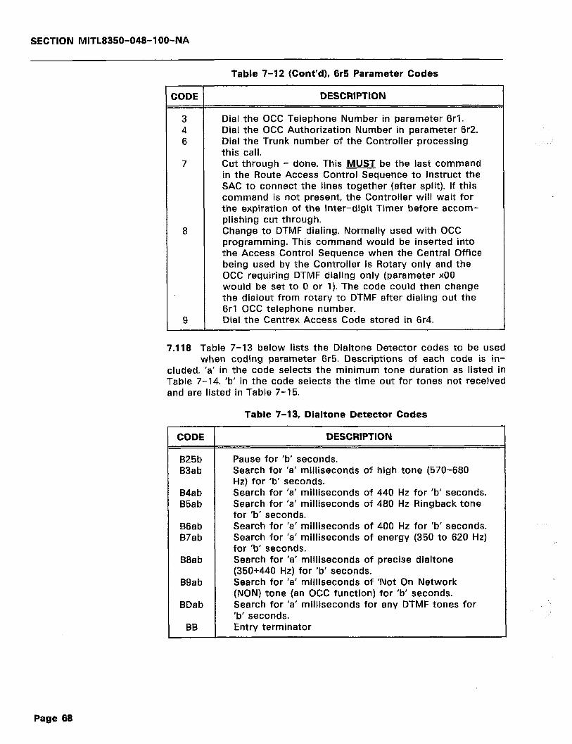
SECTION MITL8350-048-l OO-NA
Table 7-12 (Cont’d), 6r5 Parameter Codes
CODE DESCRIPTION
3 Dial the OCC Telephone Number in parameter 6rl. 4 Dial the OCC Authorization Number in parameter 6r2. 6 Dial the Trunk number of the Controller processing
this call. 7 Cut through - done. This MUST be the last command
in the Route Access Control Sequence to instruct the SAC to connect the lines together (after split). If this command is not present, the Controller will wait for the expiration of the Inter-digit Timer before accom- plishing cut through.
a Change to DTMF dialing. Normally used with OCC programming. This command would be inserted into the Access Control Sequence when the Central Office being used by the Controller is Rotary only and the OCC requiring DTMF dialing only (parameter x00 would be set to 0 or 1). The code could then change the dialout from rotary to DTMF after dialing out the 6rl OCC telephone number.
9 Dial the Centrex Access Code stored in 6r4.
7.118 Table 7-13 below lists the Dialtone Detector codes to be used when coding parameter 6r5. Descriptions of each code is in-
cluded. ‘a’ in the code selects the minimum tone duration as listed in Table 7-14. ‘b’ in the code selects the time out for tones not received and are listed in Table 7-15.
Table 7-13, Dialtone Detector Codes
CODE
B25b B3ab
B4ab B5ab
B6ab B7ab
B6ab
B9ab
BDab
BB
DESCRIPTION
Pause for ‘b’ seconds. Search for ‘a’ milliseconds of high tone (570-680 Hz) for ‘b’ seconds. Search for ‘a’ milliseconds of 440 Hz for ‘b’ seconds. Search for ‘a’ milliseconds of 460 Hz Ringback tone for ‘b’ seconds. Search for ‘a’ milliseconds of 400 Hz for ‘b’ seconds. Search for ‘a’ milliseconds of energy (350 to 620 Hz) for ‘b’ seconds. Search for ‘a’ milliseconds of precise dialtone (350+440 Hz) for ‘b’ seconds. Search for ‘a’ milliseconds of ‘Not On Network (NON) tone (an OCC function) for ‘b’ seconds. Search for ‘a’ milliseconds for any DTMF tones for ‘b’ seconds. Entry terminator
Page 68
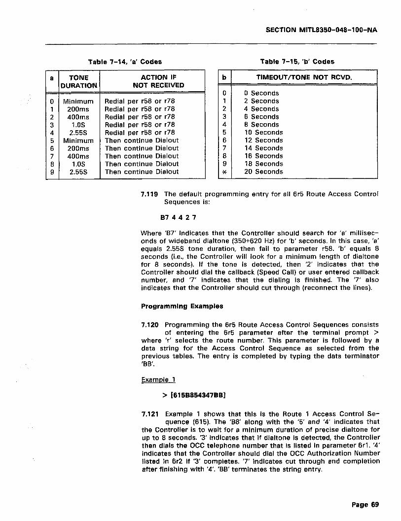
SECTION MITL8350-048-l OO-NA
-
a
=
0 1 2 3 4 5 6 7 8 9 -
Table 7-14, ‘a’ Codes Table 7-15, ‘b’ Codes
TONE IURATION
ACTION IF b TIMEOUT/TONE NOT RCVD. NOT RECEIVED
Minimum Redial per r58 or r78 200m.s Redial per r58 or r78 400ms Redial per r58 or r78
1 .os Redial per r58 or r78 2.55s Redial per r58 or r78
Minimum Then continue Dialout 200ms Then continue Dialout 400ms Then continue Dialout
1.0s Then continue Dialout 2.55s Then continue Dialout
0 0 Seconds 1 2 Seconds 2 4 Seconds 3 6 Seconds 4 8 Seconds 5 10 Seconds 6 12 Seconds 7 14 Seconds 8 16 Seconds 9 18 Seconds * 20 Seconds
7.119 The default programming entry for all 6r5 Route Access Control Sequences is:
874427
Where ‘B7’ indicates that the Controller should search for ‘a’ millisec- onds of wideband dialtone (350+620 Hz) for ‘b’ seconds. In this case, ‘a’ equals 2.55s tone duration, then fail to parameter r58. ‘b’ equals 8 seconds (i.e., the Controller will look for a minimum length of dialtone for 8 seconds). If the tone is detected, then ‘2’ indicates that the Controller should dial the callback (Speed Call) or user entered callback number, and ‘7’ indicates that the dialing is finished. The ‘7’ also indicates that the Controller should cut through (reconnect the lines).
Programming Examples
7.120 Programming the 6r5 Route Access Control Sequences consists of entering the 6r5 parameter after the terminal prompt >
where ‘r’ selects the route number. This parameter is followed by a data string for the Access Control Sequence as selected from the previous tables. The entry is completed by typing the data terminator ‘BB’.
Example 1
> [6158854347BBl
7.121 Example 1 shows that this is the Route 1 Access Control Se- quence (615). The ‘88’ along with the ‘5’ and ‘4’ indicates that
the Controller is to wait for a minimum duration of precise dialtone for up to 8 seconds. ‘3’ indicates that if dialtone is detected, the Controller then dials the OCC telephone number that is listed in parameter 6rl. ‘4’ indicates that the Controller should dial the OCC Authorization Number listed in 6r2 if ‘3’ completes. ‘7’ indicates cut through and completion after finishing with ‘4’. ‘BB’ terminates the string entry.
Page 69
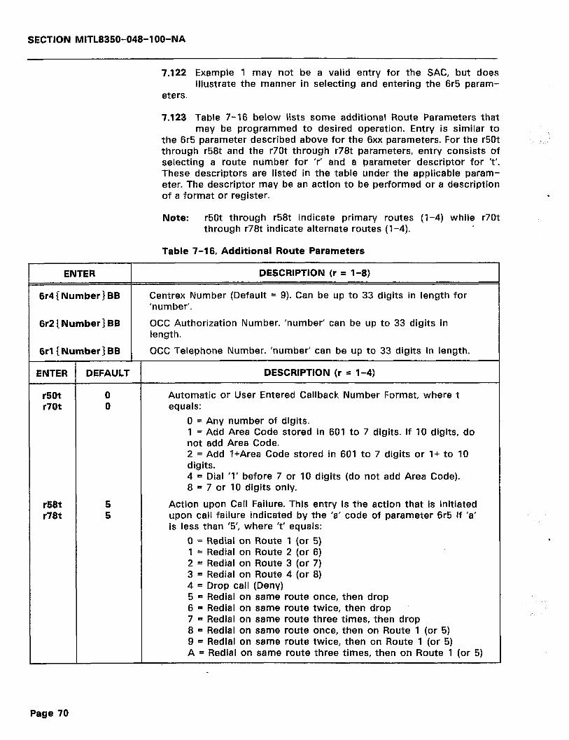
SECTION MlTL8350-048-IOO-NA
7.122 Example 1 may not be a valid entry for the SAC, but does illustrate the manner in selecting and entering the 6r5 param-
eters.
7.123 Table 7-16 below lists some additional Route Parameters that may be programmed to desired operation. Entry is similar to
the 6r5 parameter described above for the 6xx parameters. For the r50t through r58t and the r70t through r78t parameters, entry consists of selecting a route number for ‘r’ and a parameter descriptor for ‘t’. These descriptors are listed in the table under the applicable param- eter. The descriptor may be an action to be performed or a description of a format or register.
Note: r50t through r58t indicate primary routes (l-4) while r70t through r78t indicate alternate routes (l-4).
Table 7-l 6, Additional Route Parameters
ENTER
6r4 (Number) BB
DESCRIPTION (r = l-8)
Centrex Number (Default = 9). Can be up to 33 digits in length for ‘number’.
6r2 ( Number) BB OCC Authorization Number. ‘number’ can be up to 33 digits in length.
6rl( Number) BB OCC Telephone Number. ‘number’ can be up to 33 digits in length.
ENTER DEFAULT DESCRIPTION (r = l-4)
r50t r70t
0 0
Automatic or User Entered Callback Number Format, where t equals:
0 = Any number of digits. 1 = Add Area Code stored in 601 to 7 digits. If 10 digits, do not add Area Code. 2 = Add l+Area Code stored in 601 to 7 digits or l+ to 10 digits. 4 = Dial ‘1’ before 7 or 10 digits (do not add Area Code). 8 = 7 or 10 digits only.
r58t r78t
5 5
Action upon Call Failure. This entry is the action that is initiated upon call failure indicated by the ‘a’ code of parameter 6r5 if ‘a’ is less than ‘5’, where ‘t’ equals:
0 = Redial on Route 1 (or 5) 1 = Redial on Route 2 (or 6) 2 = Redial on Route 3 (or 7) 3 = Redial on Route 4 (or 8) 4 = Drop call (Deny) 5 = Redial on same route once, then drop 6 = Redial on same route twice, then drop 7 = Redial on same route three times, then drop 8 = Redial on same route once, then on Route 1 (or 5) 9 = Redial on same route twice, then on Route 1 (or 5) A = Redial on same route three times, then on Route 1 (or 5)
Page 70
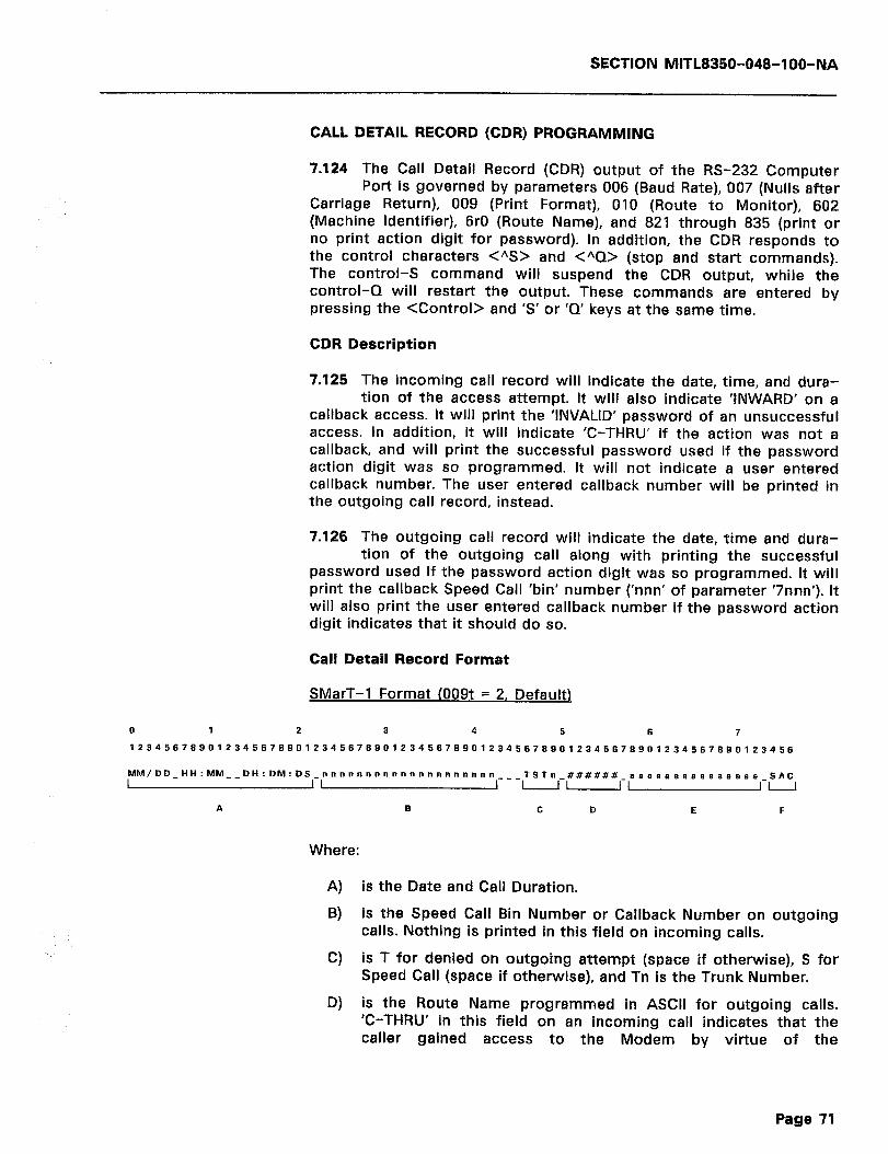
SECTION MITL8350-048-l OO-NA
CALL DETAIL RECORD (CDR) PROGRAMMING
7.124 The Call Detail Record (CDR) output of the RS-232 Computer Port is governed by parameters 006 (Baud Rate), 007 (Nulls after
Carriage Return), 009 (Print Format), 010 (Route to Monitor), 602 (Machine Identifier), 6rO (Route Name), and 821 through 835 (print or no print action digit for password). In addition, the CDR responds to the control characters <*S> and <“Q> (stop and start commands). The control-S command will suspend the CDR output, while the control-Q will restart the output. These commands are entered by pressing the <Control> and ‘S’ or ‘Q’ keys at the same time.
CDR Description
7.125 The incoming call record will indicate the date, time, and dura- tion of the access attempt. It will also indicate ‘INWARD’ on a
callback access. It will print the ‘INVALID’ password of an unsuccessful access. In addition, it will indicate ‘C-THRU’ if the action was not a callback, and will print the successful password used if the password action digit was so programmed. It will not indicate a user entered callback number. The user entered callback number will be printed in the outgoing call record, instead.
7.126 The outgoing call record will indicate the date, time and dura- tion of the outgoing call along with printing the successful
password used if the password action digit was so programmed. It will print the callback Speed Call ‘bin’ number (‘nnn’ of parameter ‘7nnn’). It will also print the user entered callback number if the password action digit indicates that it should do so.
Call Detail Record Format
SMarT-1 Format (009t = 2, Default)
a 4 5 6 7
MM/DD_HH:MM__ DH:DM:DS_nnnnnnnnnnnnnnnnnnnn I I I
___TSTn_######_eeeaasaaaea~aaaaaa_SAC 1 uu-II
A B c D E F
Where:
A) is the Date and Call Duration.
B) is the Speed Call Bin Number or Callback Number on outgoing calls. Nothing is printed in this field on incoming calls.
C) is T for denied on outgoing attempt (space if otherwise), S for Speed Call (space if otherwise), and Tn is the Trunk Number.
D) is the Route Name programmed in ASCII for outgoing calls. ‘C-THRU’ in this field on an incoming call indicates that the caller gained access to the Modem by virtue of the
Page 71
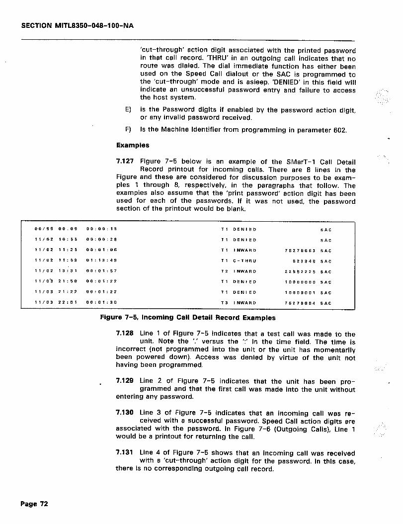
SECTION MITL8350-048-l OO-NA
‘cut-through’ action digit associated with the printed password in that call record. ‘THRU’ in an outgoing call indicates that no route was dialed. The dial immediate function has either been used on the Speed Call dialout or the SAC is programmed to the ‘cut-through’ mode and is asleep. ‘DENIED’ in this field will indicate an unsuccessful password entry and failure to access the host system.
:. ...-, . . . . :
E) is the Password digits if enabled by the password action digit, or any invalid password received.
F) is the Machine Identifier from programming in parameter 602.
Examples
7.127 Figure 7-5 below is an example of the SMarT-1 Call Detail Record printout for incoming calls. There are 8 lines in the
Figure and these are considered for discussion purposes to be exam- ples 1 through 8, respectively, in the paragraphs that follow. The examples also assume that the ‘print password’ action digit has been used for each of the passwords. If it was not used, the password section of the printout would be blank.
00/99 00.09 0o:oo: 15 Tl DENIED SAC
11/02 10: 55 00:00:26 Tl DENIED SAC
11/02 11:25 00:01:06 Tl INWARD 76276663 SAC
11/02 11:53 01:13:49 Tl C-THRU 623346 SAC
1 l/O2 13:31 00:01:57 T2 INWARD 22552225 SAC
11/0’3 21:50 00:01:22 Tl DENIED 10000000 SAC
11103 21:22 00:01:22 Tl DENIED 10000001 SAC
11/03 22:Ol 00:01:30 T3 INWARD 76276664 SAC
Figure 7-5, Incoming Call Detail Record Examples
.
7.128 Line 1 of Figure 7-5 indicates that a test call was made to the unit. Note the ‘.’ versus the ‘:’ in the time field. The time is
incorrect (not programmed into the unit or the unit has momentarily been powered down). Access was denied by virtue of the unit not having been programmed.
7.129 Line 2 of Figure 7-5 indicates that the unit has been pro- grammed and that the first call was made into the unit without
entering any password.
7.130 Line 3 of Figure 7-5 indicates that an incoming call was re- ceived with a successful password. Speed Call action digits are
associated with the password. In Figure 7-6 (Outgoing Calls), Line 1 would be a printout for returning the call.
’ _:
7.131 Line 4 of Figure 7-5 shows that an incoming call was received with a ‘cut-through’ action digit for the password. In this case,
there is no corresponding outgoing call record.
Page 72
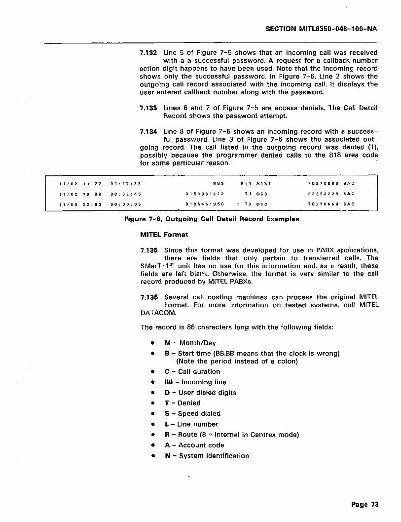
SECTION MITL8350-048-1 OO-NA
7.132 Line 5 of Figure 7-5 shows that an incoming call was received with a a successful password. A request for a callback number
action digit happens to have been used. Note that the incoming record shows only the successful password. In Figure 7-6, Line 2 shows the outgoing call record associated with the incoming call. It displays the user entered callback number along with the password.
7.133 Lines 6 and 7 of Figure 7-5 are access denials. The Call Detail Record shows the password attempt.
7.134 Line 8 of Figure 7-5 shows an incoming record with a success- ful password. Line 3 of Figure 7-6 shows the associated out-
going record. The call listed in the outgoing record was denied (T), possibly because the programmer denied calls to the 818 area code for some particular reason.
11/02 11:27 01:27:33 663 ST1 AT&T 76278663 SAC
11/02 ?3: 33 00:32:45 3153931212 Tl OCC 22662225 SAC
11/03 22:03 00:00:05 8185451958 T T3 OCC 76279664 SAC
Figure 7-6, Outgoing Call Detail Record Examples
MITEL Format
7.135 Since this format was developed for use in PABX applications, there are fields that only pertain to transferred calls. The
SMarT-1’” unit has no use for this information and, as a result, these fields are left blank. Otherwise, the format is very similar to the call record produced by MITEL PABXs.
7.136 Several call costing machines can process the original MITEL Format. For more information on tested systems, call MITEL
DATACOM.
The record is 86 characters long with the following fields:
0
0
M - Month/Day
B - Start time (BB.BB means that the clock is wrong) (Note the period instead of a colon)
C - Call duration
Ill1 - Incoming line
D - User dialed digits
T - Denied
S - Speed dialed
L - Line number
R - Route (8 = Internal in Centrex mode)
A - Account code
N - System identification
Page 73

SECTION MITL8350-048-IOO-NA
The named fields on the previous page are printed in a line as illus- trated by the line description below:
MITEL Format (009t = 1)
0 1 2 3 4 5 6 7 8
1234567890123456789012345676SJ 1234567690123456789012345676901234567890123456789912345678
_MM/DD_BB:BB__ CC:CC:CC_IIII______DDDDDDDDDDDDDDDDDDDDDDD___TSLLR~_______AAAAAAAAAAAA_NNN
where the fields are as described in Table 7-17.
7.137 Each line is ended with a CARRIAGE RETURN (ASCII 13) and LINE FEED (ASCII 10) and a programmable number of NULLS
(ASCII 0). All alphabetic fields are in upper case. The dialed number and the dialed account code fields will be numbers 0 through 9, x and #.
Table 7-17, MITEL Call Record Format Fields
FIELD COLUMN NR’ CHARS.
FORMAT MEANING
1 ? “SPAeE” M 2-6 5 MONTH; “/“; DATE
7 1 “SPACE” B 8-12 5 HOURS; “:“; MINUTES (This is the time
of the start of call rounded out to nearest minute) See note 1.
13-14 2 “SPACES” C 15-22 8 HOURS; “:“; MINUTES; ‘Y’; SECONDS
(Call duration) 23 1 “SPACE”
I 24-27 4 “TnOO” (Printed on incoming calls only; blank on outgoing calls. n is the Line Number [l-4])
28-33 6 “SPACES” D 34-56 23 This is the number that was dialed as
the “destination”. See note 2. 57-59 3 “SPACES”
T 60 1 “T” = Denied outgoing callback. “D” = Denied incoming access. “C” = Incom- ing cut through access. “SPACE” = Otherwise.
S 61 1 “S” if the call was speed called; “SPACE“ otherwise.
L,R 62-65 4 “TnOr” (Printed on outgoing calls only; blank on incoming calls. n is the Line Number [l-41. r is the route chosen 18 = no route] where r0 - r7 equals Route 1 - 8.)
66-72 7 “SPACES” A 73-84 12 Dialed account code. See note 3.
85 1 “SPACE” N 86-88 3 System Identification (first three char-
acters of parameter 602).
Page 74
SECTION MlTL8350-048-l OO-NA
NOTE 1
NOTE 2
NOTE 3
Time Display Field: If the separating character in the start of call field is a period (.), the time has not been programmed into the Dialer. Use parameter 980 to program the time. When a Dialer is powered on, it will continue to use the last time that was programmed (time at power down) but will mark the call record with a period (,). If the loss of power is only a few seconds, it will not significantly affect the timekeeping.
Dialed Number Field: This field is the Speed Call Bin Number or Callback Number on outgoing calls. Nothing is printed in this field on incoming calls.
If there is further dialing, these digits may be collected in the “account code”. If Centrex mode is being used, the user- dialed Centrex Access Code (usually a “9”) is not printed. The way to tell internal calls from external calls is to look at the route character (O-7 means a route was used, which probably dialed another “9” for the user; 8 means that the call was not routed, and the Dialer only forwarded the digits as displayed).
If an automatic callback is accessed, the speed call ‘bin’ num- ber will appear in this field.
Password Digits: This field displays the password digits that were entered by the user, provided that the password action digit allows ‘print password’ for a valid password. All invalid passwords are printed in this field. Only the first 12 digits are displayed, even though the SMarT-1’” unit can handle 23 digit passwords.
7.138 This completes the description of programming for the Control- ler. All of the parameters described in the preceding paragraphs
have been included in a handy reference table showing the default settings in Appendix C. This table is to be used for those programmers who have read and understood all of the descriptions, but wish to have a quick reference guide to the parameter numbers. The table also includes references to paragraphs that cover the particular parameter, if needed.
CONTROLLER MEMORY CAPACITY
7.139 The SAC useable memory consists of an 8K X 8 bit battery backed up Random Access Memory (RAM) chip that is capable
df holding approximately 14,500 characters. This memory area is avail- able for the storage of parameters and data at programming time. The rest of the available space is used for program execution overhead.
7.140 It is unlikely that a programmer will completely fill the RAM area with data. In the event that memory space becomes a
matter of concern, the ground rules for estimating memory usage are discussed in the paragraphs to follow starting with paragraph 7.143.
7.141 If a programmer runs out of space while programming the Controller, none of the previously programmed data will be lost.
Page 75
SECTION MITL8350-048-l OO-NA
The controller simply refuses any more programming after complete memory usage by displaying a question mark (?) on the terminal screen at the termination of each data entry on the keyboard. if it is suspected that RAM space has been completely used up, contact the distributor or the MITEL DATACOM Field Service Office. Once con- tacted, these personnel can verify that all RAM space has been used, and can possibly recommend more efficient programming techniques that can remedy the situation. As previously mentioned, the program- mer should almost never run out of RAM space for parameters and data.
7.142 Estimates of the memory space required versus the available memory space are possible. The programmer can, therefore,
estimate the memory space required before programming and can determine if the available space is insufficient.
Memory Space Estimating Method
7.143 The simplest way to determine if the the intended data base will fit into available memory is to calculate the space required
by the data. This space is then compared to the space available according to the following rules:
1)
2)
3)
4)
There are approximately 14,500 available data spaces in a freshly initialized SAC. These spaces are used to store pro- grammed data. All data to be programmed into the SAC will use this space with the exception of default settings. If a default setting is used, it will not decrease the available space. Space is mainly consumed by the parameters which are defined as ‘string’ entries and require the ‘BB’ terminator for entry. Entries that do not require the ‘BB’ terminator may be ignored in cal- culations.
A Search Table entry (parameters 801 through 815) occupies a number of spaces equal to the length of the template plus the action digits. For example, an 804 Search Table entry such as ‘804 1315 0 BB’ is four digits plus one action digit for a total of five memory spaces. The ‘804’ and ‘BB’ entries are not counted. An entry of ‘803 B9B9B9B2’ is six digits plus two action digits for a total of eight memory spaces.
A password entry (parameters 821 through 835) occupies the number of spaces equal to the length of the template (password) plus the action digits. The password ‘12345’ with a speed call callback action and 24 hour access action would be programmed as ‘825 12345 20 BB’ and would require seven spaces. The ‘825’ and ‘BB’ entries are not counted.
A callback (Speed Call) entry occupies a number of spaces equal to the length of the Speed Call plus six (an internal Controller requirement) spaces. This number must be rounded off to the next larger even number if the result is odd. For example, a Speed Call programmed as ‘7nnn 8 139311212 BB’ requires 14 spaces in memory. The eight digits of the telephone number plus six additional for the Controller equals 14. The
Page 76
SECTION iVllTL8350-048-l OO-NA
5)
Note:
7.144
‘7nnn’ and ‘BB’ entries are not counted.
Access Control strings, OCC Access Numbers, OCC Authoriza- tion Codes, etc., all count, but in general require so little space that they may be neglected for the purpose of space estima- tions.
Deleting a callback (Speed Call) with the ‘7nnnBB’ command does not reclaim all memory previously occupied by that entry. After deletion, the memory space increase only by the number of digits in the removed callback number and not by the ‘+ 6’ factor that was added in the calculation in 4) above.
Figures 7-18 through 7-20 are calculation worksheets that have been included to assist in memory space calculations. Figure
7-18 is to be used in calculating Search Table space. Figure 7-19 is to be used in calculating password space, and Figure 7-20 is to be used in calculating callback number space. These figures are located at the end of this part.
7.145 The sum of the Search Tables + Passwords + Callback Numbers must be less than approximately 14,500 spaces. Using the as-
sumption that there will be one callback number for each password, and that the 801 through 815 search tables are not required to be programmed (as is the usual case), the following generalizations can be made:
Let X = QUANTITY
PASSWORDS CALLBACKS
(Length + 2) X + (Length + 6) X = 14,500
7.146 For example, assume that the unit is programmed with all 5 digit passwords and 7 digit callback numbers. Using the equa-
tion under paragraph 7.146 above, the amount of space used would be 725 spaces as shown below:
(5 + 2)X + (7 + 6)X = 14,500
7x + 13x = 14,500
20x = 14500
14500 x= 20
X = 725
Therefore, 725 five digit passwords and 725 seven digit callback num- bers may be safely stored in the RAM memory.
7.147 Another example would be to assume that there will be twice as many passwords as callback numbers (two people at each
callback location but with different access allowances). Passwords are still 5 digits long and callback numbers are 7 digits long:
Page 77
SECTION MITL8350-048-IOO-NA
(5 + 2)2X + (7 + 6)X = 14,500
(7)2X + 13X = 14,500
14x + 13x = 14500
27X = 14500
14500 x= 27
x = 537
Therefore, 1,074 five digit passwords (2X) and 537 seven digit callback numbers may safely be stored in the RAM memory.
7.148 If the extreme case were considered and based on the formula above, up to 381 15-digit passwords and 381 15-digit callback
numbers could be stored in the RAM memory. For those who demand more detailed calculations, simultaneous solutions using X and Y un- knowns would allow calculation of uneven numbers of password/call- back quantities. Calculus formulae .would allow both lengths and quan- tities to be varied, but for simplicity, it is easier to use the charts included, with known intentions.
, .
Page 78
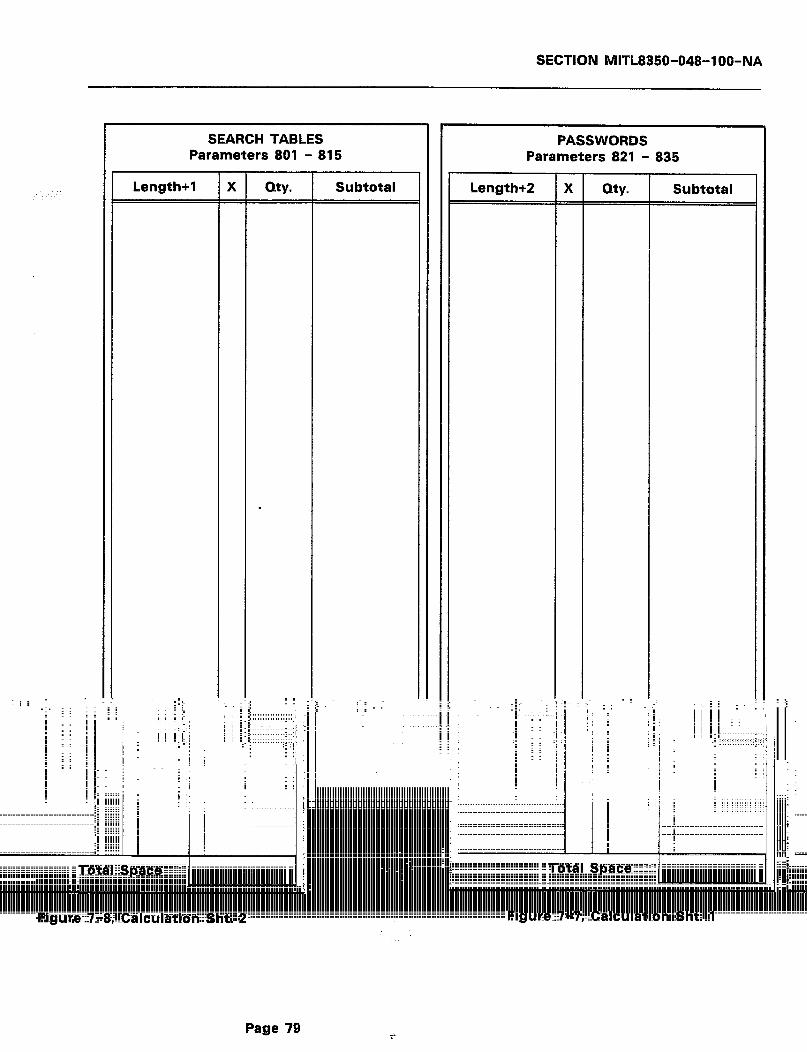
SECTION MlfL8350-048-l OO-NA
SEARCH TABLES rr PASSWORDS Parameters 801 - 815 Parameters 821 - 835
Length+1 I X QW- Subtotal Length+2 -
X =
Qty. Subtotal
i I; I I
~: --
I
. : :
I I
; : i i i i
I -i
‘;
j I
i/i I
I i
I
i I_
Page 79
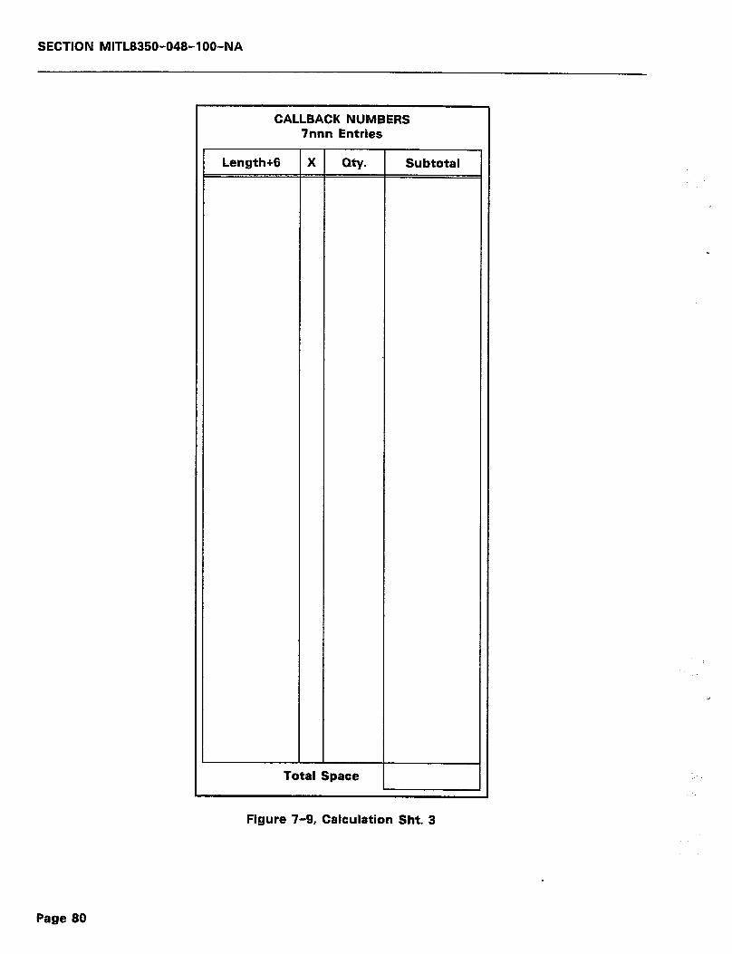
SECTION MlTL8350-048-l OO-NA
CALLBACK NUMBERS 7nnn Entries
Length+6 X Qty. Subtotal
Total Space
Figure 7-9, Calculation Sht. 3
Page 80
SECTION MITL8350-048-IOO-MA
8. TECHNICAL CIRCUIT DESCRIPTION
INTRODUCTION
8.01 This part will be added at a later date. For the present, refer to Appendix C, Figures C-I and C-2 for an overall block diagram,
and a simplified electrical diagram of the Controller, respectively.
Page 81

SECTION MITL8350-048-l OO-NA
Page 82
--- THIS PAGE INTENTIONALLY LEFT BLANK ---

SECTION MITL8350-048-l OO-NA
9. MAINTENANCE AND TROUBLESHOOTING
MAINTENANCE
9.01 The SMarT-1’” Security Access Controller, as is evident, is a fully self-contained unit. As such, it has no user repairable
parts. If the warranty seal over the unit fasteners is broken, the war- ranty is void. In case of failure, replace the Controller as follows:
1) Power down the unit. This will cut-through the subscriber side to the CO side.
2) Remove the RJ31KA31 plug from the Telco supplied socket. The shorting bars in the RJ31XKA31A will cut-through to the line. Then,
3) Replace the Controller and re-connect.
4) Proceed as if a new installation.
TROUBLESHOOTING
9.02 This part will be added at a later date.
Page 83
SECTION MITL8350-048-l OO-NA
--- THIS PAGE INTENTIONALLY LEFT BLANK ---
Page 84
SECTION MlTL8350-048-l OO-NA
APPENDIX A
FCC INTERCONNECTION REQUIREMENTS
Al.01 This equipment has been approved by the Federal Communica- tions Commission (FCC) as not being harmful to the telephone
network when connected directly to the telephone lines through the standard connection cabling provided with the unit. This section is applicable to telephone interconnection in the United States.
Al.02 Prior to the interconnection of this equipment, the local tele- phone company is to be notified; inform the company that you
have FCC-registered equipment that you wish to connect to their trunks. Give them the following information:
0 The telephone number of the line that will connect to the unit.
0 The equipment being connected is a MITEL DATACOM INC. model SMarT-I’” Security Access Controller.
0 The FCC Registration Number for the SMarT-1’” is EMP 85B-14558-LR-E.
l The FCC Ringer Equivalence Number (REN) which is 0.7B.
l The Connector Jacks required are RJ31X.
CONNECTION LIMITATIONS
Al.03 Due to the FCC Part 68 Rule, no connection can be made to party lines and to coin telephone service. This unit is designed
to be used on standard-device telephone lines. If there are any ques- tions about the telephone line, such as how many pieces of equipment may be connected to it, the telephone company will provide this information upon request.
NETWORK CHANGES
Al.04 The telephone company may make changes to it’s communica- tion service; such changes may include the change of trunk
circuits, changes in the operational characteristics of its trunks, etc. Before doing this, however, the company shall provide official notifica- tion, so that the operation of the Dialer service will not be interrupted.
MAINTENANCE LIMITATIONS
Al.05 This equipment has been registered with the FCC for direct connection to the telephone network. Under the FCC program,
the user is restricted from making any changes or repairs and from performing any maintenance operations other than those specifically included in this document.
Page A-l

SECTION MITL8350-048-l OO-NA
Al .06 There are no user repairable parts within the unit. It is sealed against user maintenance. If opened, all warranties are voided.
Al .07 No cabling or wiring changes within the unit are permitted by the user. Plug-ended cables, as detailed in this document, are used for ail external connections between the unit and the to be
telephone company interface jack.
Al.08 Power supply components and cabling is only to be changed or maintained by MITEL DATACOM INC. or by an authorized agent
of MITEL DATACOM INC. c
TROUBLE CORRECTIONS
Al.09 For all malfunctions, appropriate field service is provided by MITEL DATACOM INC. or its authorized agents.
DISCONNECTION
Al.10 If it is ever decided to permanently disconnect the SMarT-1’” Security Access Controller from the present line, please notify
the telephone company of this change.
Page A-2
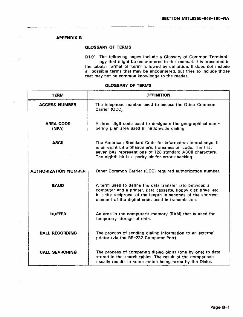
SECTION MITL8350-O48-l OO-NA
APPENDIX B
GLOSSARY OF TERMS
81.01 The following pages include a Glossary of Common Terminol- ogy that might be encountered in this manual. It is presented in
the tabular format of ‘term’ followed by definition. It does not include all possible terms that may be encountered, but tries to include those that may not be common knowledge to the reader.
GLOSSARY OF TERMS
TERM
ACCESS NUMBER
DEFINITION
The telephone number used to access the Other Common Carrier (OCC).
AREA CODE (NPA)
ASCII
A three digit code used to designate the geographical num- bering plan area used in nationwide dialing.
The American Standard Code for Information Interchange. It is an eight bit alphanumeric transmission code. The first seven bits represent one of 128 standard ASCII characters. The eighth bit is a parity bit for error checking.
AUTHORIZATION NUMBER
BAUD
Other Common Carrier (OCC) required authorization number.
A term used to define the data transfer rate between a computer and a printer, data cassette, floppy disk drive, etc.. It is the reciprocal of the length in seconds of the shortest element of the digital code used in transmission.
BUFFER An area in the computer’s memory (RAM) that is used for temporary storage of data.
CALL RECORDING The process of sending dialing information to an external printer (via the RS-232 Computer Port).
CALL SEARCHING The process of comparing dialed digits (one by one) to data . stored in the search tables. The result of the comparison usually results in some action being taken by the Dialer.
Page B-l

SECTION MITL8350-048-l OO-NA
TERM
CENTRAL OFFICE (CO)
DEFINITION
A telephone switching system used to interconnect sub- scribers together. It is usually located at a point that is cen- tral to the subscribers.
CENTRAL PROCESSING UNIT
The circuitry in a computer that controls the computer’s op- eration by interpreting and manipulating the information stored in the computer’s memory (RAM or ROM).
CENTREX Service providing direct inward and outward dialing for PABX extensions. The PABX is assigned a distinct Central Office code, and made part of the numbering plan. A main listed number will give access to the PABX operator.
CUT THROUGH MODE All digits passed directly through the Dialer (no Dialer activ- ity).
DATA TRANSMISSION RATE
See BAUD.
DDD Direct Distance Dialing that allows long distance calls to be dialed direct, rather than going through an operator.
DOT MATRIX PRINTER
A printer whose printer head forms its characters by the use of numerous metal pins that punch out the image required on paper. Another method would use jets of ink to form the image. Any method that uses a matrix of dots to form a character on paper.
DTMF DIALING A system of dialing that uses tones to transmit the dialed number to the Central Office.
END OFFICE A local central office arranged for terminating subscriber lines and provided with trunks for establishing connections to and from other central offices and toll offices.
EXTENDED AREA Telephone service that allows subscribers in one area to call SERVICE (EAS) subscribers in another area without a toll charge.
.
Page B-2
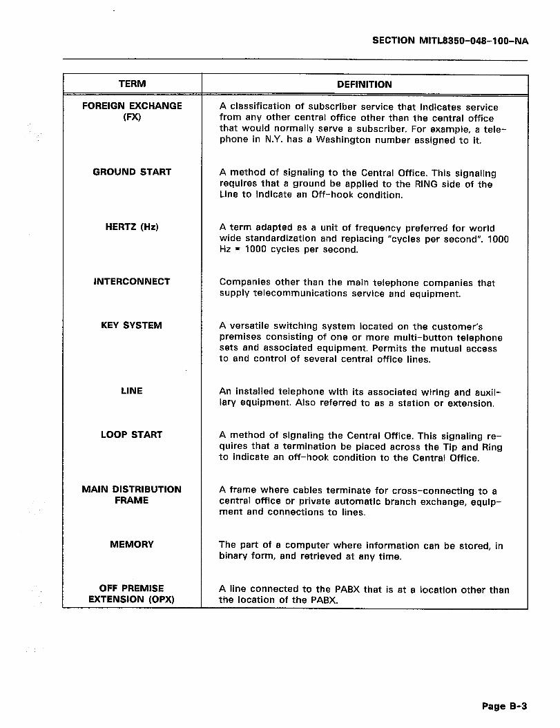
SECTION MITL8350-048-l OO-NA
TERM
FOREIGN EXCHANGE (PXI
DEFINITION
A classification of subscriber service that indicates service from any other central office other than the central office that would normally serve a subscriber. For example, a tele- phone in N.Y. has a Washington number assigned to it.
GROUND START A method of signaling to the Central Office. This signaling requires that a ground be applied to the RING side of the Line to indicate an Off-hook condition.
HERTZ (Hz)
INTERCONNECT
A term adapted as a unit of frequency preferred for world wide standardization and replacing “cycles per second”. 1000 Hz = 1000 cycles per second.
Companies other than the main telephone companies that supply telecommunications service and equipment.
KEY SYSTEM A versatile switching system located on the customer’s premises consisting of one or more multi-button telephone sets and associated equipment. Permits the mutual access to and control of several central office lines.
LINE An installed telephone with its associated wiring and auxil- iary equipment. Also referred to as a station or extension.
LOOP START A method of signaling the Central Office. This signaling re- quires that a termination be placed across the Tip and Ring to indicate an off-hook condition to the Central Office.
MAIN DISTRIBUTION FRAME
A frame where cables terminate for cross-connecting to a central office or private automatic branch exchange, equip- ment and connections to lines.
MEMORY The part of a computer where information can be stored, in binary form, and retrieved at any time.
OFF PREMISE A line connected to the PABX that is at a location other than EXTENSION (OPX) the location of the PABX.
Page B-8
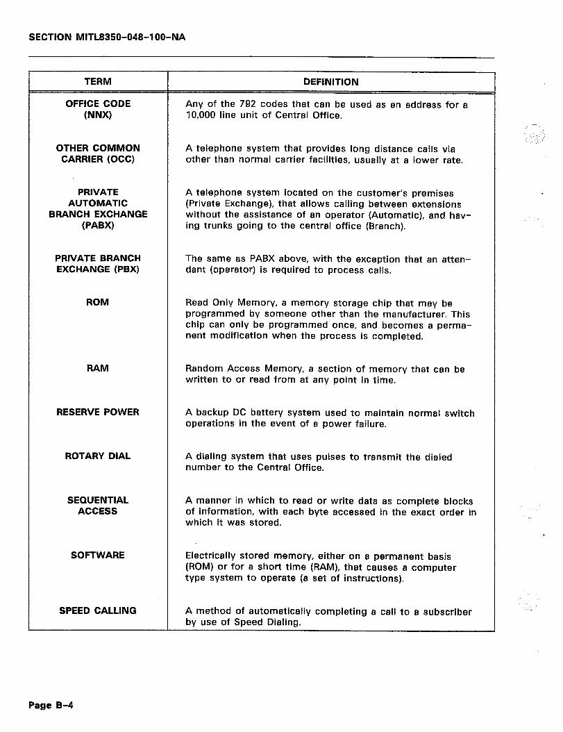
SECTION MITL835W048-IOO-NA
TERM --
OFFICE CODE (NNX)
OTHER COMMON CARRIER (OCC)
PRIVATE AUTOMATIC
BRANCH EXCHANGE (PABX)
PRIVATE BRANCH EXCHANGE (PBX)
ROM
DEFINITION
Any of the 792 codes that can be used as an address for a 10,000 line unit of Central Office.
A telephone system that provides long distance calls via other than normal carrier facilities, usually at a lower rate.
A telephone system located on the customer’s premises (Private Exchange), that allows calling between extensions without the assistance of an operator (Automatic), and hav- ing trunks going to the central office (Branch).
The same as PABX above, with the exception that an atten- dant (operator) is required to process calls.
Read Only Memory, a memory storage chip that may be programmed by someone other than the manufacturer. This chip can only be programmed once, and becomes a perma- nent modification when the process is completed.
RAM Random Access Memory, a section of memory that can be written to or read from at any point in time.
RESERVE POWER A backup DC battery system used to maintain normal switch operations in the event of a power failure.
ROTARY DIAL A dialing system that uses pulses to transmit the dialed number to the Central Office.
SEQUENTIAL ACCESS
A manner in which to read or write data as complete blocks of information, with each byte accessed in the exact order in which it was stored.
SOFTWARE Electrically stored memory, either on a permanent basis (ROM) or for a short time (RAM), that causes a computer type system to operate (a set of instructions).
SPEED CALLING A method of automatically completing a call to a subscriber by use of Speed Dialing.
-.- :
.
_
Page B-4

SECTION MlTL8350-048-l OO-NA
TERM
SPEED DIALING
DEFINITION
The automatic dialing of a stored number by a microproces- sor or similar unit. The process presupposes that the user will dial a single digit to cause the unit to dial many digits automatically, saving time and effort.
STATIC Interference caused by electrical disturbances in the atmo- sphere, or any man-made electromagnetic device.
SWITCHING SYSTEM
TIE TRUNK
TIP & RING
A device that interconnects two or more subscriber circuits.
A trunk between two PABX’s.
Indicates each side of a pair of wires used throughout the telephone industry. The first wire is the tip and the second wire is the ring. Normally, the tip is ground and the ring is battery.
TOLL OFFICE The office that handles toll calls (calls where there are addi- tional charges).
TRUNK A telephone circuit or channel between two Central Offices, or between a Central Office and a PBX or PABX.
VOICE FREQUENCY The sound waves produced by the vibration of the voice box when speaking.
WIDE AREA TELEPHONE SERVICE
(WATS)
For a basic monthly charge, the customer is allowed to make calls within a specific region without any additional charges. A WATS line can be incoming or outgoing, but not both. Outgoing WATS is OUTWATS and incoming WATS is INWATS.
Page B-5

SECTION MITL8860-048-l OO-NA
--- THIS PAGE INTENTIONALLY LEFT BLANK ---
Page B-6
SECTION MITL8350-048-100-NA
APPENDIX C
ADDITIONAL INFORMATION
Cl.01 Figures C-l and C-2 on the following pages are a block dia- gram and a simplified electrical diagram for the SMarT-1’” Se-
curity Access Controller. Table C-l is a listing of the standard 7-bit ASCII codes followed by the code equivalents. Table C-2 contains Legal Dialer Programming Input Characters.
Cl.02 Table C-3 lists the Parameter Defaults along with descriptions. The table also lists reference pages where the particular com-
mands and descriptions may be found.
Page C-l
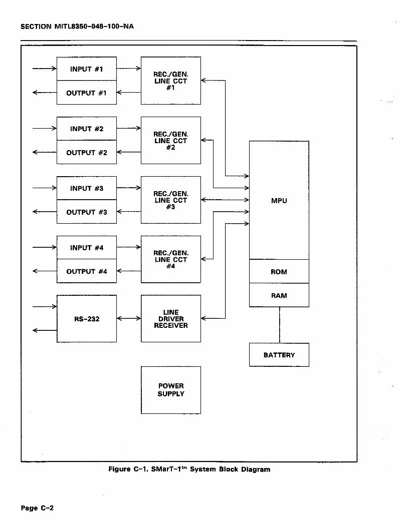
SECTION MlTL8350-048-IOO-MA
> INPUT #l > RECJGEN. LINE CCT <
#l < OUTPUT #l (
> INPUT #2 > RECJGEN. LINE CCT
#2 < OUTPUT #2 <
> INPUT #3 > > RECJGEN. LINE CCT < > MPU
< OUTPUT #3 < #3
>
>
> INPUT #4 > RECJGEN. LINE CCT
#4 < OUTPUT #4 < ROM
POWER SUPPLY
Figure C-l, SMarT-ltm System Block Diagram
Page C-2

SECTION MITL8350-048-I 00-Nk
DTMF RX 7
RINGING DETECT
I
I
I I I 1 I r - - - &~TFN;- - - - - - - --_-- -I
INPUTS
I
I
PROM
Figure C-2, SMarT-1’” Simplified Electrical Diagram
Page C-3
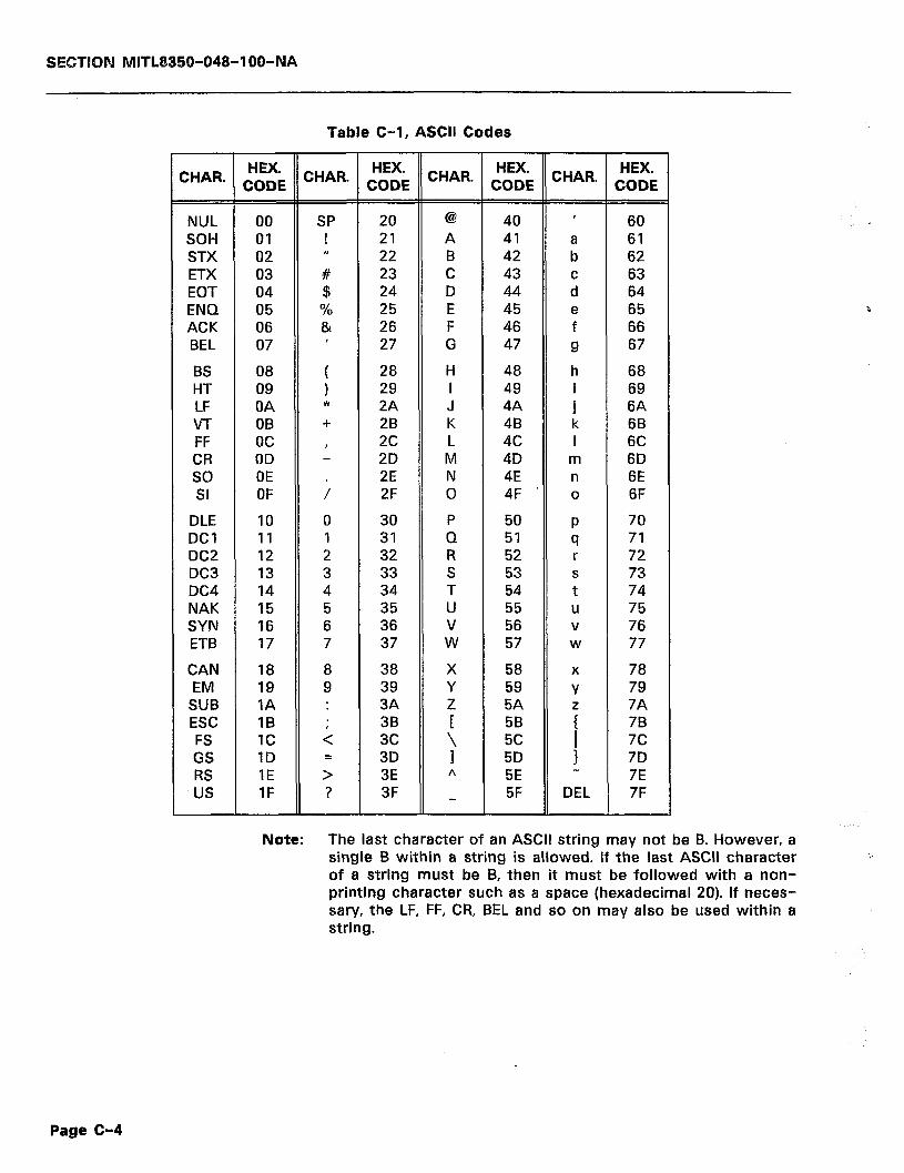
SECTKIN MITL8350-048-I OO-NA
Table C-l, ASCII Codes
CHAR. t;;E HEX.
CHAR. CODE CHAR. t;EE CHAR. ;;tE
NUL 00 SP SOH 01 ! STX 02 ti ETX 03 # EOT 04 $ ENQ 05 % ACK 06 & BEL 07 ’
BS 08 ! HT 09 LF OA *
VT OB + FF oc CR OD I SO OE SI OF ;
DLE 10 0 DC1 11 1 DC2 12 2 DC3 13 3 DC4 14 4 NAK 15 5 SYN 16 6 ET6 17 7
CAN 18 8 EM 19 9
SUB 1A : ESC IB .
:: FS 1c GS 1D = RS 1E > us 1F ?
20 d 40 ’ 60 21 A 41 61 22 B 42 : 62 23 C 43 63 24 D 44 z 64 25 E 45 e 65 26 F 46 f 66 27 G 47 g 67
28 H 48 h 68 29 I 49 i 69 2A J 4A i 6A 28 K 48 k 6B 2c L 4c I 6C 2D M 4D m 6D 2E N 4E n 6E 2F 0 4F’ o 6F
30 P 50 P 70 31 Q 51 9 71 32 R 52 r 72 33 S 53 s 73 34 T 54 t 74 35 U 55 U 75 36 v 56 v 76 37 W 57 W 77
38 X 58 X 78 39 Y 59 Y 79 3A Z 5A 7A 3B 5B
; 5C ; 78
3c 3D 5D \ 3: 3E A 5E - 7E 3F _ 5F DEL 7F
Note: The last character of an ASCII string may not be B. However, a single B within a string is allowed. If the last ASCII character v
of a string must be B, then it must be followed with a non- printing character such as a space (hexadecimal 20). If neces- sary, the LF, FF, CR, BEL and so on may also be used within a string.
Page C-4
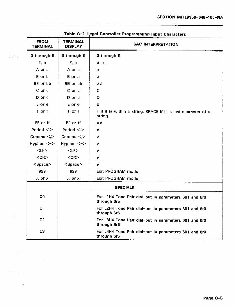
SECTION MlTL8350-048-1 OO-l\)lA.
FROM TERMINAL
Table C-2, ~
TERMINAL DISPLAY
0 through 9 0 through 9
#, * #, *
A or a A or a
B or b B or b
BB or bb BB or bb
C or c C or c
D or d D or d
E or e E or e
F or f F or f
FF or ff
Period <.>
Comma <,>
Hyphen C->
<LF>
<CR>
<Space>
999
X or x
FF or ff
Period <.>
Comma <,>
Hyphen <->
<LF>
<CR>
<Space>
999
X or x
!gal Controller Programming Input Characters
SAC INTERPRETATION
0 through 9
#, *
*
#
##
C
D
E
F if it is within a string. SPACE if it is last character of a string.
##
#
#
#
#
#
#
Exit PROGRAM mode
Exit PROGRAM mode
SPECIALS
co For LlH4 Tone Pair dial-out in parameters 601 and 6rO through 6r5
Cl For L2H4 Tone Pair dial-out in parameters 601 and 6rO through 6r5
c2
c3
For L3H4 Tone Pair dial-out in parameters 601 and 6rO through 6r5
For L4H4 Tone Pair dial-out in parameters 601 and 6rO through 6r5
Page C-5
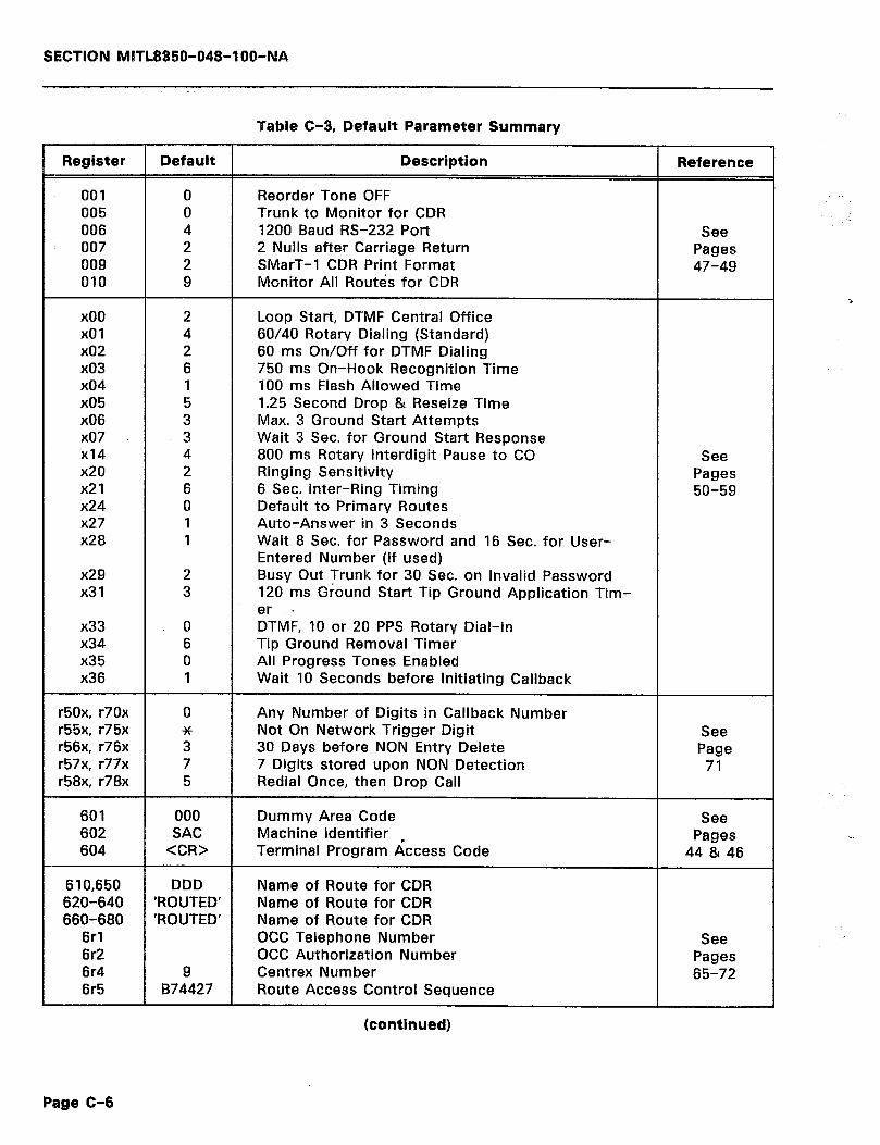
SECTION MITL8350-048-l OO-NA
Table C-3, Default Parameter Summary
Register Default Description Reference
001 0 Reorder Tone OFF 005 0 Trunk to Monitor for CDR 006 4 I200 Baud RS-232 Port See
: 007 2 2 Nulls after Carriage Return Pages 009 2 SMarT-1 CDR Print Format 47-49 010 9 Monitor All Routes for CDR
x00 2 Loop Start, DTMF Central Office x01 4 60/40 Rotary Dialing (Standard) x02 2 60 ms On/Off for DTMF Dialing x03 6 750 ms On-Hook Recognition Time x04 1 IO0 ms Flash Allowed Time x05 5 1.25 Second Drop 81 Reseize Time x06 3 Max. 3 Ground Start Attempts x07 . 3 Wait 3 Sec. for Ground Start Response XI4 4 800 ms Rotary Interdigit Pause to CO See x20 2 Ringing Sensitivity Pages x21 6 6 Sec. Inter-Ring Timing 50-59 x24 0 Default to Primary Routes x27 I Auto-Answer in 3 Seconds x28 I Wait 8 Sec. for Password and I6 Sec. for User-
Entered Number (if used) x29 2 Busy Out Trunk for 30 Sec. on Invalid Password x31 3 120 ms Ground Start Tip Ground Application Tim-
er . x33 0 DTMF, IO or 20 PPS Rotary Dial-in x34 6 Tip Ground Removal Timer x35 0 All Progress Tones Enabled x36 1 Wait 10 Seconds before Initiating Callback
r50x, r70x 0 Any Number of Digits in Callback Number r55x, r75x * Not On Network Trigger Digit See r56x, r76x 3 30 Days before NON Entry Delete Page r57x, r77x 7 7 Digits stored upon NON Detection 71 r58x, r78x 5 Redial Once, then Drop Call
601 000 Dummy Area Code See 602 SAC Machine Identifier Pages 604 <CR> Terminal Program Access Code 44 81 46
610,650 620-640 660-680
6rI 6r2 6r4 6r5
DDD ‘ROUTED’ ‘ROUTED’
9 874427
Name of Route for CDR Name of Route for CDR Name of Route for CDR OCC Telephone Number OCC Authorization Number Centrex Number Route Access Control Sequence
(continued)
See Pages 65-72
Page C-6
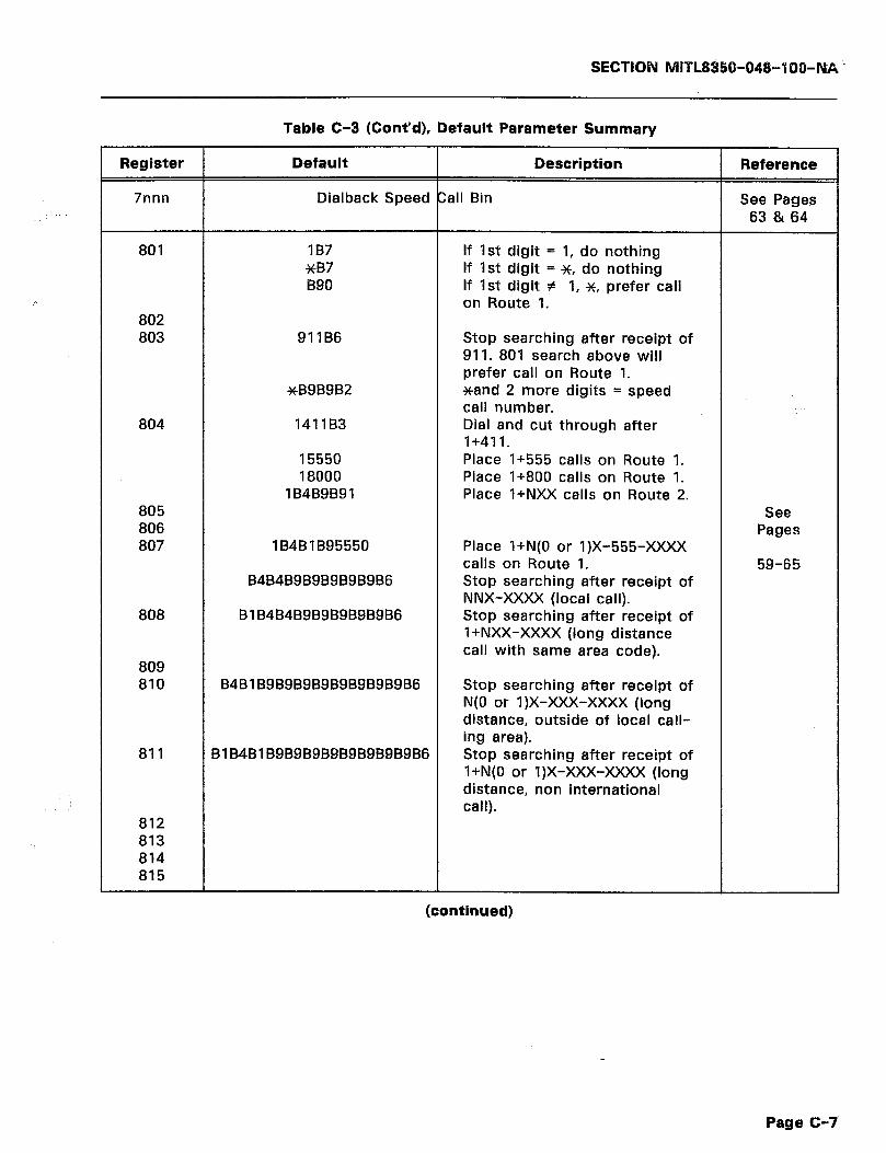
SECTION MlTL8850-048-7 66-N& _
Table C-3 (Cont’d), Default Parameter Summary
Register Default Description Reference
7nnn Dialback Speed Call Bin See Pages 63 81 64
801
802 803
804
805 806 807
808
809 810
811
812 813 814 815
lB7 xB7 B90
911B6
xB9B9B2
141183
15550 18000
lB4B9B91
184BlB95550
B4B4B9BgBgBgBgB6
BlB4B4BgBgBgBgBgB6
B4BlB9B9B9B9B9B9B9B9B6
BlB4BlB9B9B9B9B9B9B9B9B6
If 1st digit = 1, do nothing If 1st digit = *, do nothing If 1st digit # 1, x, prefer call on Route 1.
Stop searching after receipt of 911. 801 search above will prefer call on Route 1. *and 2 more digits = speed call number. Dial and cut through after I+41 1. Place I+555 calls on Route 1. Place 1+800 calls on Route 1. Place l+NXX calls on Route 2.
Place l+N(O or 1)X-555-xXxX calls on Route 1. Stop searching after receipt of NNX-XXXX (local call). Stop searching after receipt of l+NXX-XXXX (long distance call with same area code).
Stop searching after receipt of N(0 or 1)X-XXX-xXxX (long distance, outside of local call- ing area). Stop searching after receipt of l+N(O or 1)X-XXX-xXxX (long distance, non international call).
See Pages
59-65
(continued)
Page C-7
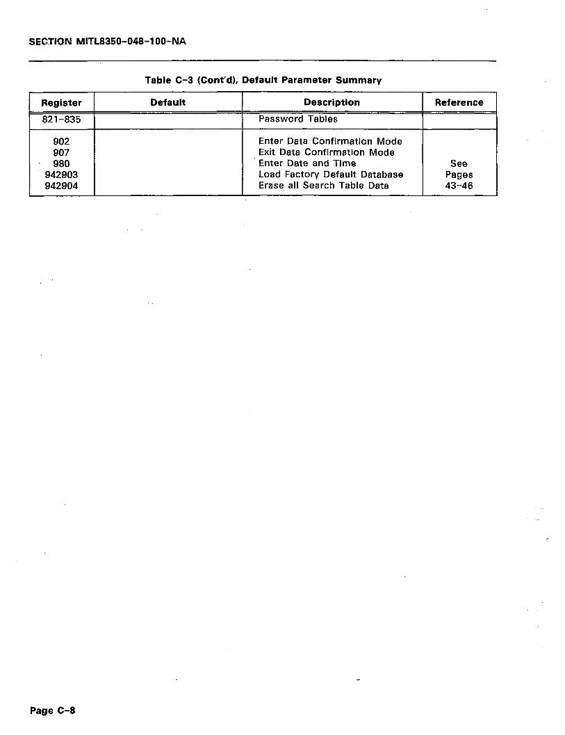
SECTlrQN M1TL8350-048-l OO-NA
Table C-3 (Cont’d), Default Parameter Summary
Register
82 l-835
902 907 980
942903 942904
Default Description
Password Tables
Enter Data Confirmation Mode Exit Data Confirmation Mode Enter Date and Time Load Factory Default Database Erase all Search Table Data
Reference
See Pages 43-46
Page C-8

SECTION MBTL885Cb048-IOO- til% ?
APPENDIX D OVERALL TOPICAL INDEX
CONTENTS PAGE CONTENTS
ACCESS CODE SEE GLOSSARY OF TERMS
ACCESS CONTROL SEQUENCE SEE PROGRAMMING ROUTING PARAMETERS
ACR SEE ADAPTIVE CALL ROUTING
ACTION DIGIT DEFINITIONS
SEE SEARCH TABLE PROGRAMMING ACTION DIGIT DESCRIPTIONS
SEE TABLE 7-11 _.________ .._ .._ _...
ADAPTIWE CALL ROUTING
B-l
67
6
64
SEE VERSATILE PROGRAMMING BAUD
SEE GLOSSARY OF TERMS BAUD RATE
SEE CALL RECORDING/R.%232 PORT SEE RS-232 PORT SPECIFICATIONS
BB
65.66
SEE NOTES ON DATA ENTRY BIT EIGHT SENSE
SEE RS-232 PORT SPECIFICATIONS 11 BITS PER CHARACTER
SEE CONTROLLER DESCRIPTION ADDITIONAL ROUTE PARAMETERS
SEE TABLE 7-16 ALLOWABLE VOLTAGE
6 SEE RS-232 PORT SPECIFICATIONS 11 BRIDGE CLIPS
SEE RJ31X/CA31A USOC JACK AND CABLE 20 BUFFER
SEE HARDWARE SPECIFICATIONS
ALTERNATE ROUTING
70
10 SEE GLOSSARY OF TERMS B-1
SEE LEAST COST ROUTING APPENDIX A
CONNECTION LIMITATIONS CONNECTOR JACKS .._..........._ .._..... DISCONNECTION : FCC INTERCONNECTION REQUIREMENTS FCC REGISTRATION NUMBER MAINTENANCE LIMITATIONS NETWORK CHANGES _.........._........, RINGER EQUIVALENCE NUMBER TROUBLE CORRECTIONS
APPENDIX B GLOSSARY OF TERMS
APPENDIX C
6
A-l A-l A-2
A-l A-l A-l
A-l A-l
A-2
B-l
ASCll CODES................................ ASCll TABLE .._ _.. _.. _.. _.. DEFAULT PARAMETER SUMMARY
DIAGRAMS __ _... __. _.. _.. .__ _.._ _.... LEGAL CONTROLLER PROGRAMMING INPUT CHARACTERS SMarT-1 SIMPLIFIED ELECTRICAL DIAGRAM
SMarT-1 SYSTEM BLOCK DIAGRAM AREA CODE
C-l c-4
..c-1
C-l c-5 c-4
c-4
CALL ANSWER TIMER
SEE TABLE 7-4 SEE TRUNK RELATED PARAMETERS
CALL DETAIL RECORD FORMAT
SEE CALL DETAIL RECORD PROGRAMMING CALL DETAIL RECORD PROGRAMMING
CALL DETAIL RECORD FORMAT
CDR DESCRIPTION SEE DETAILED PROGRAMMING DESCRIPTIONS
CALL DETAIL RECORDING
SEE SECURITY CALL FAILURE ACTION
SEE TABLE 7-16 CALL RECORDING
SEE GLOSSARY OF TERMS CALL RECORDING/RS-232 PORT
SEE CONTROLLER DESCRIPTION CALL SEARCHING
SEE GLOSSARY OF TERMS
AREA CODE (NPA)
B-l
SEE GLOSSARY OF TERMS AREA CODE/OFFICE CODE/CALL SEARCHING
SEE CONTROLLER DESCRIPTION
ASCII
B-l
6
SEE GLOSSARY OF TERMS
ASCII CODES
B-l
SEE GLOSSARY OF TERMS CALLBACK FEATURE
SEE SECURITY _. ____ .._ _. CALLBACK NUMBER FORMAT
SEE TABLE 7-16 CALLBACK OPERATION
SEE PROGRAMMING
CALLBACK PROGRAMMING TERMINAL DISPLAY SEE FIGURE 7-1
CAPABILITIES
SEE APPENDIX C __, _.... _. __ .._ ., __ __. _, SEE TABLE C-l
ASCII STRING
SEE FEATURES AND CAPABILITIES CDR DESCRIPTION
SEE NOTES ON DATA ENTRY. ASCII TABLE
C-l c-4
35
SEE APPENDIX C AUTOMATIC CALLBACK ACCESS
SEE DETAILED OPERATING DESCRIPTIONS
AUTOMATIC CALLBACK PROGRAMMING SEE DETAILED PROGRAMMING DESCRIPTIONS .
c-4
25
43.63
SEE CALL DETAIL RECORD PROGRAMMING CDR PRINT FORMAT
SEE SYSTEM PARAMETERS SEE TABLE 7-3
CENTRAL OFFICE (CO) SEE GLOSSARY OF TERMS
CENTRAL OFFICE CONNECTIONS
SEE RJBlX/CABlA USOC JACK AND CABLE CEBTRAL PROCESSING UNIT (CPU)
SEE GLOSSARY OF TERMS CENTREX
B SEE NOTES ON DATA ENTRY.
BASIC PROGRAMMING SEE INTRODUCTION
BATTERIES
SEE INITIALIZATION SEE VERSATILE PROGRAMMING
BATTERV BACKUP
SEE SYSTEM POWER
BATTERY FEED SEE HARDWARE SPECIFICATIONS
BATTERY TVPE SEE INITIALIZATION
34
33
29 6
5
9
29
PAGE
. . ...6
B-l
6 11
34
SEE GLOSSARY OF TERMS CENTREX NUMBER
SEE TABLE 7-16 co
SEE GLOSSARY OF TERMS
COMMUNICATIONS REQUIREMENTS SEE INITIALIZATION SEE VERSATILE PROGRAMMING
CONNECTION LIMITATIONS
SEE APPENDIX A CONNECTION PROCEDURE
SEE CONNECTIONS CONNECTIONS
B-2
16.20
51 52
71
71
71 71
23
70
6-1
6
B-l
23
70
34
37
r. 3
71
48 67.48
B-Z
20
B-2
70
B-2
29 7
A-l
Page D-5

CONTENTS PAGE
RJ31X/CA31A USOC JACK AND CABLE F&232 PORT CONFIGURATION SEE ELECTRICAL/MECHANICAL SPECIFICATIONS
SEE UNPACKING, INSTALLATION AND ORDERING INFORMATION CONNECTOR JACKS
SEE APPENDIX A
CONTROLLER DESCRIPTION AOAPTIVE CALL ROUTING AREA CODE/OFFICE CODE/CALL SEARCHING
CALL RECORDING/AS-232 PORT LEAST COST ROUTING LINES/MODELS
NETWORK COMPATIBILITY SEE GENERAL DESCRIPTION SYSTEM POWER
CONTROLLER MEMORY CAPACITY MEMORY SPACE ESTIMATING METHOD SEE PROGRAMMING
CURRENT SEE HARDWARE SPECIFICATIONS
CUT THROUGH ACCESS
20 20 11
16
A-l
6 6
6 6 5
5 3 5
76 75
9
SEE OPERATIONAL SEQUENCES 24 SEE DETAILED OPERATING.OESCRIPTION 27
CUT THROUGH MODE
SEE GLOSSARY OF TERMS B-2 SEESECURITY.. .:._.:..: :i.. .:r.... _. _. 23
CONTENTS PAGE
DISCONNECTION
SEE APPENDIX A A-2 DOCUMENT APPENDICES DESCRIPTION
SEE DOCUMENT OVERVIEW. 1 DOCUMENT CONVENTIONS
SEE INTRODUCTION 2 DOCUMENT HISTORV
SEE INTRODUCTION .._ __._ _.... _. 2 DOCUMENT NUMBERING :
SEE DOCUMENT OBJECTIVES 1 DOCUMENT OBJECTIVES
SEE INTRODUCTION 1 DOCUMENT OVERVIEW
SEE INTRODUCTION . . . .._........._......._........... 1 DOCUMENT PART DESCRIPTIONS
SEE DOCUMENT OVERVIEW.............................. 1 ‘. DOCUMENT TITLE
SEE DOCUMENT OBJECTIVES 1 DOT MATRIX
SEE GLOSSARY OF TERMS E-2 DOT MATRIX PRINTER
-Tf’.j, ,;, ,:
DATA STRING 50 52
SEE PROGRAMMING 34
DATA TRANSMISSION RATE SEE GLOSSARY OF TERMS B-2
DATA VERIFICATION
SEE TABLE 7-4 SEE TRUNK RELATED PARAMETERS
DTMF RECEIVER
SEE HARDWARE SPECIFICATIONS DTMF SENDER
SEE HARDWARE SPECIFICATIONS
10
10
SEE PROCEDURAL STEPS 36
DC BALANCE SEE HARDWARE SPECIFICATIONS I’. 9
DCE
EAS
SEE RS-232 PORT CONFIGURATION ._ : 20 DDD
SEE AREA CODE/OFFICE CODE/CALL SEARCHING 6 SEE GLOSSARY OF TERMS 6-2
DEFAULT LOAD
SEE GLOSSARY OF TERMS B-2 ELECTRICAL/MECHANICAL SPECIFICATIONS
SEE SPECIFICATIONS 11 SEE TABLE 3-3 11
ELLIPSIS
SEE PROGRAMMING . .___ ____ ___._...., ._._..., .____.. 7 DEFAULT PARAMETER SUMMARV
SEE APPENDIX C :. C-l DEFAULT PROGRAMMING PARAMETERS
SEE TABLE 7-l 33.34 DEFECTIVE EQUIPMENT
SEE DOCUMENT CONVENTIONS .._.. _................... 2 END OFFICE
SEE GLOSSARY OF TERMS B-2 ENTER DATA CONFIRMATION MODE
SEE SYSTEM PARAMETERS 45 SEE TABLE 7-2 44
ENTER DATE AND TIME
SEE REPACKING 13 SEE SYSTEM PARAMETERS 45 DELETE ALL SEARCH TABLE ENTRIES ENTER DATE/TIME
SEE SYSTEM PARAMETERS 45 SEE SYSTEM PARAMETERS 44
SEE TABLE 7-2 44 SEE TABLE 7-2 44
DETAILED OPERATING DESCRIPTION ENTERING CALLBACK NUMBER
OTHER OPERATIONAL PROCEDURES 28
SEE OPERATING DESCRlmlON 25 WITH MODEMS .~. 25
DETAILED PROGRAMMING DESCRIPTIONS
SEE PROCEDURAL STEPS 36
ENTERING DATE AND TIME
AUTOMATIC CALLBACK PROGRAMMING 63 CALL DETAIL RECORD PROGRAMMING 71 NON-CONTROLLER PERTINENT PARAMETERS. 55
PASSWORD PROGRAMMING 59 PROGRAMMING ROUTING PARAMETERS 67 SEARCH TABLE PROGRAMMING . .._...____ .___ ..__ 64
SEE PROGRAMMING . . . . . . . . . . . . . . . . . . .._..__ 42 SPEED CALL 63 SYSTEM PARAMETERS :. 43
TRUNK RELATED PARAMETERS 49 DETECTOR TIMEOUT CODES
SEE PROCEDURAL STEPS 36 ENTERING MACHINE IDENTIFIER
SEE PROCEDURAL STEPS 36 ENTERING PASSWORD
SEE PROCEDURAL STEPS 36 ENTERING PROGRAM MODE
SEE INITIALIZATION PROCEDURE ENTERING PROGRAMMING MODE
SEE PROCEDURAL STEPS ENTRV TERMINATOR
SEE PROGRAMMING
EXIT DATA CONFIRMATION MODE SEE SYSTEM PARAMETERS SEE TABLE 7-2
EXIT PROGRAM MODE
SEE SYSTEM PARAMETERS SEE TABLE 7-2
EXITING PROGRAM MODE
SEE INITIALIZATION PROCEDURE EXTENDED AREA SERVICE (EAS)
SEE GLOSSARY OF TERMS
30
36
34
44.45 44 SEE TABLE 7-14
SEE TABLE 7-15 DIAGRAMS
SEE APPENDIX C
DIALTONE SEE HARDWARE SPECIFICATIONS
DIALTONE DETECTOR CODES
SEE TABLE 7-13 DIMENSIONS
SEE ELECTRICAL/MECHANICAL SPECIFICATIONS
69
69
C-l
10
.66
11
SEE GLOSSARY OF TERMS B-2 DTMF CUT THROUGH ACCESS
SEE PROGRAMMING . . . . . . . . . . . . . . . . . . . . . .._ 42 DTMF DIALING
SEE GLOSSARY OF TERMS B-2 DTMF DIALING RATE
44 44
30
B-2
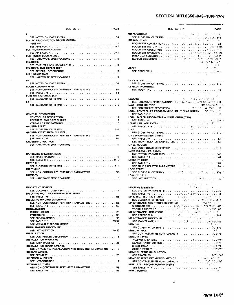
CONTENTS PAGE
F SEE NOTES ON DATA ENTRY.
FCC INTERCONNECTION REQUIREMENTS
GENERAL .._.............. SEE APPENDIX A
FCC REGISTRATION NUMBER SEE APPENDIX A
FCC RINGER EQUIVALENCE SEE HARDWARE SPECIFICATIONS
FEATURES
34
1 A-l
A-l
9
SEE FEATURES AND CAPABILITIES
FEATURES AND CAPABILITIES SEE GENERAL DESCRIPTION
FEED RESISTANCE SEE HARDWARE SPECIFICATIONS
FF SEE NOTES ON DATA ENTRY.
FLASH ALLOWED TIME
SEE NON-CONTROLLER PERTINENT PARAMETERS. SEE TABLE 7-5
FOREIGN EXCHANGE (FX) SEE GLOSSARY OF TERMS
FX SEE GLOSSARY OF TERMS
3
3
9
34
57 55
B-3
B-3
GENERAL DESCqlPTlON
CONTROLLER DESCRIPTION FEATURES AND CAPABILITIES VERSATILE PROGRAMMING
GROUND START SEE GLOSSARY OF TERMS
GROUND START TRIES NUMBER
SEE NON-CONTROLLER PERTINENT PARAMETERS SEE TABLE 7-5
GROUNDING VOLTAGE SEE HARDWARE SPECIFICATIONS
HARDWARE SPECIFICATIONS SEE SPECIFICATIONS SEE TABLE 3-1
HERTZ (Hz) SEE GLOSSARY OF TERMS
HIT TIMING
SEE NON-CONTROLLER PERTINENT PARAMETERS HUMIDITY
SEE HARDWARE SPECIFICATIONS
IMPORTANT NOTICES SEE DOCUMENT OVERVIEW
INCOMING DIGIT RECOGNITION TYPE TIMER SEE TABLE 7-5
INCOMING RINGING SENSITIVITY SEE NON-CONTROLLER PERTINENT PARAMETERS. SEE TABLE 7-5
INITIALIZATION
56
INTRODUCTION ____ _......_ _........ PROCEDURE ____._ _._.......................
SEE PROGRAMMING SEE TABLE 7-l .., .___.__..__. __. __
SEE VERSATILE PROGRAMMING
lNlTlALl2ATlON PROCEDURE SEE lNlTlALlZATlON .
INSTALLATION SEE CONTROLLER DESCRIPTION
INSTALLATION PROBLEMS
56 56
29 30
33 33.34
6
29.30
5
SEE WITH MODEMS _. __ ._ ______ _. _. _.__ _.. __
INSTALLATION REQUIREMENTS SEE UNPACKING, INSTALLATION AND ORDERING INFORMATION
INSTANT ACCESS
25
13
SEE SECURITY _._. __ _.. ..__ __.. __.__ __._ ._
INTENDED AUDIENCE SEE INTRODUCTION .__. ___...._ ______._ __._ ._
INTER-RING TIMER
23
2
SEE NON-CONTROLLER PERTINENT PARAMETERS. 56
SEE TABLE 7-5 56
9 9.10
B-3
56
10
CONTENTS.:’ PAGE
INTERCONNECT SL. I _’ :
SEE GLOSSARY OF TERMS : -. : ._ :,. .:;i: ? ..i.i B-3 INTRODUCTION ” , * ,, , ; ., 1
DOCUMENT CONVENTIONS : I :-: .:I’. .A! : ..!,Z DOCUMENT HISTORY .:j_ I .;:riI’.~:~r2C DOCUMENT OBJECTIVES / :A::‘+ i :.;.I DOCUMENT OVERVIEW i”! : .‘. -C. L<!. i;‘.. ‘!‘F..‘ 1.7: INTENDED AUDIENCE : ._ I-. _ (/ .‘f.-32 READER COMMENTS : : _ L::.. : c : .‘: ;:! i’l . ..ii .2
, A... 4 : .‘j,!S ; - -“-. . ..!.
JACKS .-. ( ,-.<; SEE APPENDIX A . . : _.. A-l
KEY SYSTEM SEE GLOSSARY OF TERMS :‘:‘.,. . :_ : :. B-3
KEVSLOT MOUNTING
SEE MOUNTING 16 ,?; .: : 1. .’
i
LEAKAGE 7 ,. A :. . - : :. i‘, I
SEE HARDWARE SPECIFICATIONS .,i.‘: c. ‘,:6.i? .;,:;.(: .,. ..-.(;. i‘3..,:. : : : .:: 9
LEAST COST ROUTING ; .7P.? “‘jil;).‘, pi ‘I~.
SEE CONTROLLER DESCRIPTION ? .? : ? .q.‘% ‘C ::‘: .:? 6 LEGAL CONTROLLER PROGRAMMING INPUT GHARACTERS
-:., ,-. .I , _.
SEE TABLE C-2 _’ 5 LEGAL DIALER PROGRAMMING INPUT CHARACTERS
SEE APPENDIX C _. _!,.: ‘C-4 : LENGTH OF NON ENTRY .- :’
SEE TABLE 7-16 .‘. 70‘ LINE ,..
SEE GLOSSARY OF TERMS E-3
LINE DROP/RESEIZURE TIME SEE TABLE 7-4 50 SEE TRUNK RELATED PARAMETERS _‘_ I. 52
LINES/MODELS SEE CONTROLLER DESCRIPTION 1:: 5
LOAD DEFAULT DATABASE
SEE SYSTEM PARAMETERS : : .,:,.-‘. . . .;. .45 SEETAELE7-2 .._.._._.___.,._.__._____.._....__.._ :44
LOCKOUT TIMER :_
SEE TABLE 7-4 :. : I-51 SEE TRUNK RELATED PARAMETERS .:: : : t 53
LOOP START
SEE GLOSSARY OF TERMS r:.;. 1.: :!. .‘: _.:‘_ ._ :. E-3 : LOSS OF DATA
SEE lNlTlALlZ4TlON _-:; . . I, 29 ”
.a ..,’ ,
MACHINE IDENTIFIER L .‘, ;
SEE SYSTEM PARAMETERS _:, :. 46 SEE TABLE 7-2 *.‘? ::‘~.“.“;‘;‘f ‘.::‘s ..-,:-. 2: ,. .: !I -44
MAIN DISTRIBUTION FRAME .<‘, --,,> i.. ., .?‘:’ ~ !
SEE GLOSSARY OF TERMS ‘l:J _’ :. : :..: .-,.li : :: :?q;>. B-3
MAINTENANCE AND TROUBLESHOOTING ‘,:qi?, :: 4 !
MAINTENANCE ; .‘.,*‘:: :P;‘:::-: ._ s!:“‘. :.!‘.r:. i$,. q.:? 1183 ”
TROUBLESHOOTING :‘. .c: 1 : t.:.:.. : . . .‘\, d,!;e‘i 63 MAINTENANCE LIMITATIONS ..i’ .: ;,i- . ,‘-A :,
SEE APPENDIX A :,1_ .‘: : _- .._ ?.’ i a-1
MAINTENANCE PROCEDURE i .!,, ,\ ,,
SEE MAINTENANCE . ‘. . ‘/.I ‘_ ?.ii::;d:“63 MEMORV .i. r I..,
SEE GLOSSARY OF TERMS . 1”. 8’3 MEMORV FULL .-: I,,?
SEE CONTROLLER MEMORY CAPACITY .‘:: : 95 MEMORY SPACE ,. ,;’
PASSWORD ENTRIES : !‘.:‘.:78‘*1 SEARCH TABLE ENTRIES . :‘.-76
SPEED CALLS : .‘. -? ‘77 STRING ENTRIES . .‘:\c;~.?S’;
MEMORY SPACE CALCULATION -. .I
SEE EXAMPLES j.?.‘:. 77.. ! MEMORV SPACE ESTIMATING METHOD ,a,, ;.: -:.x
SEE CONTROLLER MEMORY CAPACITY : ::: .‘,.: .‘;“:i 76:‘.
MITEL CALL RECORD FORMAT FIELDS ,.
SEE TABLE 7-17 . 74’ MITEL FORMAT r.

,’ CONTENTS . . PAGE
SEE~LLDETAILRECORDFORNIAT...::: ____: _.._....._.__.. 73 MODE OF OPERATION
SEE RS-232 PORT SPECIFICATIONS 11
MODEM SETUP SEE TESTING CONTROLLER INSTALLATION ‘_ 37
MODEMS
SEE DETAILED OPERATING DESCRIPTION 25
MOUNTING s,:,; :._.:_ -
SEE ELECTRICAL/MECHANICAL SPECIFICATIONS 11
SEE UNPACKING. INSTALLATION AND ORDERING INFORMA 16 MOJJNTING HARDWARE
SEE MOUNTING . 16
MOUNTING INFORMATION
ENVIRONMENTAL REOUIREMENTS 16
$EE INSTALLATION REQUIREMENTS 13.16
MULTI-UNIT PACKAGE SEE SHIPPING AND RECEIVING 13
SEE CONTROLLER DESCRIPTION 5 NETWORK OVERRIDE CODES
NETWORK CHANGES .c SEE APPENDIX A A-l
NETWORK COMPATIBILITY
SEE TABLE 7-9 ,_ 63.64 NON ENTRV PERIOD
<SEE TABLE 7-16 70 NON-CONTROLLER PERTINENT PARAMETERS
SEE DETAILED PROGRAMMING DESCRIPTIONS 55 SEE TABLE 7-5 55
NOT ON NETWORK TRIGGER DIGIT SEE TABLE 7-16 70
NOTES ON DATA ENTRY
SEE PROGRAMMING 34 NOTES ON ORDER OF PASSWORD PROGRAMMING
SEE PROGRAMMING ..__ .___ .___ ._. _. _.._ .., 35 NPA
SEE AREA CODE/OFFICE CODE/CALL SEARCHING 6 .-SEE GLOSSARY OF TERMS r, I if,e_. : B-l
NUMBER OF NULLS FOR CDR SEE SYSTEM PARAMETERS 46
NM
fiEE AREA CODE/OFFICE CODE/CALL SEARCHING 6 SEE GLOSSARY OF TERMS .;: B-4
NXX NUMBERS
SEE GLOSSARY OF TERMS B-4
1,‘; - i I<:_,:_
occ SEE AREA CODE/OFFICE COD~&ALL SEARCHING 6
*SEE GLOSSARY OF TERMS . . B-4
OCCAREACODE SEE SYSTEM PARAMETERS 46 SEETABLE 7-2 .._.__ .___ ____ .___._. _.., 44
OCC AUTHORIZATION NUMBER SEE TABLE 7-16 .: _ : ._ +i... ,. ..; 70
0% TELEPHONE NUMBER
SEE TABLE 7-16 70 OFF PREMISE EXTENSION (OPX) .:.
SEE GLOSSARY OF TERMS ;-. B-3
OFF-HOOK CURRENT SEE HARDWARE SPECIFICATIONS 9
OFFICE CODE (NNX) ,;,. _- ..’ *,j_
SEE GLOSSARY OF TERMS . . B-4
Or?-HOOK RECOGNITION TIME SEE NON-CONTROLLER PERTINENT PARAMETERS 57
SEE TABLE 7-5 . 55 OPEN CIRCUIT VOLTAGE
SEE HARDWARE SPECIFICATIONS : 9 OPERATING DESCRIPTION
DETAILED OPERATING DESCRIPTION 25 .OPERATIONAL SEQUENCES 23
SECURITY . . . . . . . . . . . . . . . . . _. __ .._. .___ ___. 23 OPERATING RANGE
SEE HARDWARE SPECIFICATIONS 10
OPERATIONAL PARAMETERS -i,.; SEE DETAILED PROGRAMMING DESCdlPTlONS 42
OPERATIONAL SEQUENCES
CONTENTS PAGE
AUTOMATIC CALLBACK ACCESS 24
CUT-THROUGH ACCESS _......... _.. _.......... 24 SEE DETAILED OPERATING DESCRIPTION 27
SEE OPERATING DESCRIPTION 23 SEE OPERATIONAL SEQUENCES 24 USER ENTERED CALLBACK ACCESS 24
OPERATIONAL STEPS SEE DETAILED OPERATING DESCRIPTIONS 25.26
OPX
SEE GLOSSARY OF TERMS B-3 ORDERING INFORMATION
SEE TABLE 4-1 21
SEE UNPACKING, INSTALLATION AND ORDERING INFORMATION 21
OTHER COMMON CARRIER (OCC) SEE GLOSSARY OF TERMS B-4
OTHER OPERATIONAL PROCEDURES SEE DETAILED OPERATING DESCRIPTION 26
PABX
SEE REPACKING
SEE PROGRAMMING
SEE GLOSSARY OF TERMS
PARITV
PACKING MATERIAL
PARAMETER IDENTIFIER
SEE RS-232 PORT SPECIFICATIONS PART NUMBERS
SEE ORDERING INFORMATION :. SEE TABLE 4-l
SEE UNPACKING. INSTALLATION AND ORDERING INFORMATION PASSWORD ACTION DIGITS
SEE TABLE 7-7
PASSWORD ENTRIES MEMORYSPACE . . . . . . . .._........_ __........ _..
PASSWORD FORMAT
SEE FIGURE 7-4 PASSWORD PROGRAMMING
PASSWORD PROGRAMMING EXAMPLES
SEE DETAILED PROGRAMMING DESCRIPTIONS PASSWORD PROGRAMMING EXAMPLES
EXAMPLE 1 . . . . . . . . . . . . . . . . . . . . . . . . . . . .._.. __ EXAMPLE Z................................, EXAMPLE 3 . . . . . . .._ __. _..._. __.. __
SEE PASSWORD PROGRAMMING PASSWORD PROTECTION
SEE CONTROLLER DESCRlmlON PASSWORD TABLE DESCRIPTIONS
SEE TABLE 7-6 PASSWORD TVPE
SEE SECURITY
PASSWORD VERIFICATION SEE DETAILED OPERATING DESCRIPTION
PASSWORDS
SEE DETAILED OPERATING DESCRIPTIONS SEE SECURITY
PBX
SEE GLOSSARY OF TERMS POWER
SEE ELECTRICAL/MECHANICAL SPECIFICATIONS POWER DOWN CUT THROUGH MODE
SEE SYSTEM POWER POWER OUTAGE
SEE SYSTEM POWER POWER RECEPTACLE RECOMMENDATIONS
SEE POWER REQUIREMENTS POWER REQUIREMENTS
B-4
13
34
11
76
59
62
43.59
62
62 62 62
3
61
23
27
26 23
B-4
11
5
5
16
SEE UNPACKING, INSTALLATION AND ORDERING INFORMATION 16 PRINTER CONNECTION
SEE RS-232 PORT CONFIGURATION PRIVATE AUTOMATIC BRANCH EXCHANGE (PBX)
SEE GLOSSARY OF TERMS
PRIVATE BRANCH D(CHANGE SEE GLOSSARY OF TERMS
PROGRAM ACCESS CODES
SEE INITIALIZATION PROGRAM VERIFICATION
USER ENTERED CALLBACK OPERATION
20
B-4
B-4
29
41
CONTENTS
PROGRAMMING
CONTROLLER MEMORY CAPACITY DETAILED PROGRAMMING DESCRIPTIONS
DTMF CUT THROUGH ACCESS FOR USER ENTERED CALLBACK NUMBER INTRODUCTION .._ _......
NOTES ON ORDER OF PASSWORD PROGRAMMING PROGRAMMING FOR CALLBACK OPERATION SEE VERSATILE PROGRAMMING
TESTING CONTROLLER INSTALLATION PROGRAMMING EXAMPLES
SEE PROGRAMMING ROUTING PARAMETERS SEE SEARCH TABLE PROGRAMMING
PROGRAMMING FOR CALLBACK OPERATION PROCEDURAL STEPS
SEE PROGRAMMING PROGRAMMING ROUTING PARAMETERS
6R5 ACCESS ROUTE
ACCESS CONTROL SEQUENCES PROGRAMMING EXAMPLES SEE DETAILED PROGRAMMING DESCRIPTIONS
PROGRAMMING TIMEOUT SEE INITIALIZATION PROCEDURE
PROGRAMMING TRUNKS
SEE TRUNK RELATED PARAMETERS PROGRAMMING USER ENTERED CALLBACK
PROGRAM VERIFICATION SEE PROGRAMMING
PROGRESS TONES SEE DETAILED OPERATING DESCRIPTIONS
SEE OPERATIONAL SEQUENCES SEE SECURITY SEE TABLE 7-4
SEE TRUNK RELATED PARAMETERS
RAM SEE CONTROLLER MEMORY CAPACITY SEE GLOSSARY OF TERMS
RE-INITIALIZATION SEE INITIALIZATION
RE-ORDER TONE
SEE SYSTEM PARAMETERS SEE TABLE 7-3
READER COMMENTS
SEE INTRODUCTION .._ _. __ .___ .._ _.. __ REASONS FOR INlTlALlZATlON
SEE INITIALIZATION
RECEIVING SEE UNPACKING. INSTALLATION AND ORDERING INFORMATION
RECOGNITION TIME, TIP TO GND
SEE HARDWARE SPECIFICATIONS REPACKING
SEE SHIPPING AND RECEIVING REPAIRED UNIT
SEE INITIALIZATION REQUIREMENTS PRIOR TO INITIALIZATION
SEE INITIALIZATION RESERVE POWER
SEE GLOSSARY OF TERMS
RETURN LOSS SEE HARDWARE SPECIFICATIONS
RINGER EQUIVALENCE NUMBER
SEE APPENDIX A RINGER IMPEDANCE
SEE HARDWARE SPECIFICATIONS
RINGING SENSITIVITY
SEE HARDWARE SPECIFICATIONS RJalWCA3lA USOC JACK AND CABLE
SEE CONNECTIONS . . . . . . . . . ___.._. ___...__ ROM
SEE GLOSSARY OF TERMS ROTARY DIAL
SEE GLOSSARY OF TERMS ROTARY DIALING RATE
SEE TABLE 7-4 SEE TRUNK RELATED PARAMETERS
ROTARY INTER-DIGIT PAUSE
PAGE CON’TENTS ‘.,:‘ PAGE
75 42
42
39 33
35 34
7
37
69
66
35
34
67
67 69 67
31
50
41
39
25 23
23 51.52
54
75 : ‘B-4
29
48 47
2
29
13
29
B-4
9
A-l
9
9
20
B-4
B-4
50 52
SEE NON-CONTROLLER PERTINENT PdiANiE1’ERS. :‘r :‘: i.. .-. ::.‘%I SEE TABLE 7-5 : .J. . :?j:.. :: 51:.
ROTARY RECEIVER -_ ,,:-,.: _ I. .., II :.,I
.:
SEE HARDWARE SPECIFICATIONS !‘!! ,?. :::qt?: <i ROTARY SENDER “;&:..~~>:, ;;!‘;,‘ ..,.(, ‘.:b;,’ .;-: :.;z
SEE HARDWARE SPECIFICATIONS .‘?‘%@?W
ROUTE RELATED PARAMETERS .. T4iF ’ .?q >!,!i, i ;_..:z,-: ‘.‘j.:,,. ‘::G :,r
SEE DETAILED PROGRAMMING DESCRlmlONS .‘j141%$! f ROUTE TO MONITOR
., : .:::,y .:or ::..:!b’,.‘:‘-<;. :., ,I !1 I??
SEE SYSTEM PARAMETERS ‘f’:‘;‘. -_ ::+, ,+?‘,T,:,’ : y.::.. :, . . _I_ _. .:y: .349 SEE TABLE 7-3 :.. :.:‘<’ I,.’ _‘: :‘?“&W
ROUTING .?l!,, i;!,
SEE LINES/MODELS .‘: : .“.‘: ..‘; : ‘?? ;‘! 9 RS-232 BAUD RATE
SEE SYSTEM PARAMETERS ::.r!‘: 1’:; .;. _‘_: _‘. :‘. ‘. 46
SEE TABLE 7-3 :‘. :.i. .‘:‘47 -’ RS-232 CONNECTOR 1;,, ‘,
SEE RS-232 PORT CONFIGURATION 20 RS-232 PORT
SEE CALL RECORDINGIRS-232 PORT .@i .‘:I. : 6 ‘. RS-232 PORT CONFIGURATION
SEE CONNECTIONS .;?‘: :‘j .“.?‘*. :>: .‘%.‘.20 .” RS-232 PORT SPECIFICATIONS .,;.:, ,,:‘y’ I,, <zlij; ,c I- -1:
SEE SPECIFICATIONS -.‘i~!%.~~~!‘?%+? :????l !‘c!
SEE TABLE 3-2 . .? :.,::.!!: .-:r:l r50t :o,‘liP .?i ,‘j y,.::
SEETABLE7-16 .._........ .___.._.__.. _.._._ :..::L::-‘.?$ mit !; 1 i- .,,wisq I .,,:,lit, ;.I-.n ‘:2.? :C, ‘c. -:1; ?j
SEE TABLE 7-16 :. ::?_;;:‘:: ..:??‘:‘. ‘. ‘. : : “T :.! 7b r56t - . . _Ie z-1.
SEE NON ENTRY PERIOD i-r-,.-. :;;:: ‘?.‘. : :‘: _‘. ‘7611’ r57t
SEE LENGTH OF NON ENTRY :..-. :::_ 76.”
r5Ett .) */
SEE CALL FAILURE ACTION’ :~.‘“.‘“:,!‘:‘: i%!‘:-:. ‘. :‘:‘. : : 70 :
:i
SEARCH TABLE DEFAULTS .!‘-T’ ,.z.+_ . . -_ _ . , ‘>
SEE SEARCH TABLE PROGRAMMING : :‘“d6 SEARCH TABLE DESCRIPTIONS
,. _. Zq,‘.,?_i)bi
SEE TABLE 7-10 .I. j-65 SEARCH TABLE ENTRIES i _I’
MEMORY SPACE _. :.: f‘.-‘.‘:?.c. _‘_: .:c _. .: ! :?f6 SEARCH TABLE PROGRAMMING ; ,, ; 1 I:.‘.
ACTION DIGIT DEFINITIONS : :!: :‘64il
PROGRAMMING EXAMPLES .‘:n.‘.‘. ? ‘_I : ‘66 SEARCH TABLE DEFAULTS 86 SEE DETAILED PROGRAMMING DESCRIPTIONS 64
SEARCH TABLES L-b
SEE DETAILED PROGRAMMlNG%&CR@TlOtiS~. .:-: ?? .z:‘!‘:: .“. ,, ‘. 43 SEE LINES/MODELS .‘.“::-.-. ic! ‘_ ? 1:‘; ‘:‘. :: 5
SECURITY ?I ;:” ,_:fl;:, :
SEE CONTROLLER DESCRlFnON :;? :? .? ‘.‘1.!‘. ;.‘i:i”.~‘. ?‘.a3
SEE OPERATING DESCRIPTION ; :. ? I”.“. i i3 SELECT DEFAULT ROUTE ‘3’)“’ ;t !“,,!:’ -i:‘i~.(Tu; -:,.j
SEE NON-CONTROLLER PERTINENT PARAMETERS. : ! ‘_ 4 !:!.“. 886 SEE TABLE 7-5 .‘?“?‘,‘~.? ?!??? !13? 56:.
SENSING RESISTANCE ,< : .I “$ ./ 7 -:‘?y.>
SEE HARDWARE SPECIFICATIONS .‘:- .!‘:‘. .‘?%?“.?? ;h’: :“!~. -9.-y SEQUENTIAL ACCESS
: <+ I. , ;;,-..- I ; “?.
SEE GLOSSARY OF TERMS .?.?r: :‘.-; .‘?:;%4 ” SHIPPING . ‘2;:’ “,:“.. _; .i _I ,_ ,,.. .;:1;
SEE UNPACKING, INSTALLATION AND ORDERING INFORMJi7~0iQ!(??. ?‘lZi”
SHIPPING AND RECEIVING _‘. ” ‘; i ‘,l, ,, . :
REPACKING . .?~!‘T :’ : ?:t’. ‘:?‘?13”-
UNPACKING ?. ‘. :‘. :‘” :?1”. 1;!+ ‘. :: .‘: ‘I’:. i3
SHORT CIRCUIT CURRENT I.. -1’
SEE HARDWARE SPECIFICATIONS ‘I :‘. I’. .‘I’? .,i :Ejc: SIMPLIFIED ELECTRICAL DIAGRAM :” ~,. ..z.;
SEE FIGURE C-2 !‘. :‘? .‘?!‘?+!%~ SINGLE UNIT PACKAGE ,.‘. ,.:‘) n-1 ;.s,!‘=j(,
SEE SHIPPING AND RECEIVING :_’ .l: .- :‘!a:,: ‘.i’: 1’13 SMART-l FORMAT : 7 ,‘i(l’-‘::
EXAMPLES ‘:l’.!‘?? .:?!‘!- :st.?l
SEE CALL DETAIL RECORD FORMAT .::-!:;!-. . I’.? ?:‘i*: y.“?. .-+. il
SMarT-1 SIMPLIFIED ELECTRICAL DIAGRAM ;;! ,<“,I’ h ‘{T!.j -u?.,.
SEE APPENDIX C .<. .‘i ::. ?‘:-:‘.‘. .‘.-i .‘.‘..: Iti- SEE FIGURE C-2 . .J ‘!“:‘iJ. .? +!?;: :?‘ti3
:->;- ,. CONTENTS ,>;: PAGE
SMa!T-1 SVSTEM BLOCK DIAGRAM SEE APPENDIX C C-l SEE FIGURE C-l
SO@VARE .j.._j SEE GLOSSARY OF TERMS ‘:
SPEWAL PAFIAMETERS
4
B-4
SEE DETAILED PROGRAMMING DESCRIPTIONS 42
SPECIFICATIONS El,ECTRICAL/MECHANICAL SPEClFlCATlOl$3
HeRDWARE SPECIFICATIONS . .-. RS-232 PORT
SPEEp CALL PROGRAMMING SEE AUTOMATIC CALLBACK PROGRAMMING
11
9 : ‘11
63
SPEED CALLING SEE GLOSSARY OF TERMS B-4
SPEED CALLS MEMORY SPACE .
SPEED DIALING SEE GLOSSARY OF TERMS
SPEEDCALLS SEE DETAILED PROGRAWlMlNG DESCRIFIIONS
STATIC SEE GLOSSARY OF TERMS ;_.7z,. _
STR!JdG ENTRIES MEMORY SPACE
SUITABLE TERMINAL SEE lNlTlALlZATlON
SWifCHING SYSTEM 5 .- :> &E GLOSSARY OF TERMS .‘: :
SVSTEM BLOCK DIAGRAM .:; -t .( ** -.I. SEE FIGURE C-l
SYSTEM MAINTENANCE SEE MAINTENANCE AND TROUBLESHOOTING
SVSTEM PARAMETERS SEE DETAILED PROGRAMMING DESCRIPTIONS SEE TABLE 7-2
SVSTEM POWER SEE CONTROLLER DESCRIPTION
SVSTEM TROUBLESHOOTING SEE MAINTENANCE AN0 TROUBLESHOOTING
SYSTEM WIDE OPERATION PARAMETERS SEE TABLE 7-3
TECHNICAL CIRCUIT DESCRIPTION INTRODUCTION . . . . . .._ __., . .._.
TEMPERATURE SEE HARDWARE SPECIFICATIONS .
TERMINAL ACCESS CODE SEE PROGRAMMING FOR CALLBACF QpEfJAT!O?
TERMINAL CONNECTION SEE Rs-232 PORT CONFIGURATION
TEF+llNAL DISPLAV USER ENTERED CALLBACK PROGRAMMING SEE FIGURE 7-3 ‘.I: ‘.
TERtvllNAL PROGRAM SECURITV CODE
77
B-5
43
B-5
76
29
8-5
4
63
42.43 43
5
63
47.48
61
10
35
20
42
SFE TABLE 7-2 . .7T.,T;,Tj:; ,. 44 TERhUAL PROMPT
kkE DOCUMENT CONVENTIONS 2
SEE NOTES ON DATA ENTRY .tlJ;_; eLii,. r : 35
TER?+lNAL SECURll-V PROGRAM COtrE SEE SYSTEM PARAMETERS 46
TERMINATION SEE HARDWARE SPECIFICATIONS , 9
TERMINATOR SEE NOTES ON DATA ENTRY.
TESTING CONTROLLER INSTALLATION
‘~TUAL TESTING . . MODEM SETUP . SEE PROGRAMMING . THEORY OF TEST .
THEGRV OF TEST
35
36 37 37
37
SEE TESTING CONTROLLER INSTALLATION 37
TIE TRUNK SEE GLOSSARY OF TERMS . . E-5
TIME-OF-DAY CODES SEE TABLE 7-6 . . 61
TIMER BEFORE PROCESSING CALLBACK SEE TABLE 7-4 . 52
CONTENTS PAGE
SEE TRUNK RELATED PARAMETERS 54 TIP IIt RING
SEE GLOSSARY OF TERMS B-5
TIP GROUND APPLICATION TIMER SEE NON-CONTROLLER PERTINENT PARAMETERS. 58 SEE TABLE 7-5 56
TIP GROUND REMOVAL TIMER SEE NON-CONTROLLER PERTINENT PARAMETERS. 56 SEE TABLE 7-5 57
TIP GROUND TIMER
SEE NON-CONTROLLER PERTINENT PARAMETERS 57 SEE TABLE 7-5 .._........ __ ..__ .._.... __... 56
TOLL OFFICE SEE GLOSSARY OF TERMS E-5
TROUBLE CORRECTIONS
SEE APPENDIX A A-2 TRUNK
SEE GLOSSARY OF TERMS B-5 TRUNK RELATED PARAMETERS
SEE DETAILED PROGRAMMING DESCRlmlONS 42 SEE DETAILED PROGRAMMING DESCRIPTIONS 49 SEE TABLE 7-4 SEE TRUNK RELATED PARAMETERS
TRUNK TO MONITOR FOR CDR SEE SYSTEM PARAMETERS SEE TABLE 7-3
TYPE OF CENTRAL OFFICE
SEE TABLE 7-4 SEE TRUNK RELATED PARAMETERS
TVPE OF UNIT
SEE APPENOIX A TYPES OF CO LINES
SEE NETWORK COMPATIBILITY TVPES OF DIALING
SEE NETWORK COMPATIBILITY
50 52
46 47
50 52
A-l
5
5
UNAUTHORIZED ACCESS
SEE CONTROLLER DESCRIPTION 5 UNIT STORAGE
SEE INlTlALlZATlON 29 UNPACKING
SEE SHIPPING AND RECEIVING 13 UNPACKING PROCEDURE
SEE UNPACKING ..____._....___....._
UNPACKING, INSTALLATION AND ORDERING INFORMATION CONNECTIONS _............ _....... INSTALLATION REQUIREMENTS
MOUNTING __ .__ .._ ___ _. ORDERING INFORMATION POWER REQUIREMENTS
SHIPPING AND RECEIVING USER ENTERED CALLBACK ACCESS
SEE DETAILED OPERATING DESCRlmlONS SEE OPERATIONAL SEQUENCES
USER ENTERED CALLBACK PROGRAMMING TERMINAL DISPLAY
VERSATILE PROGRAMMING
DESCRlmlON INITIALIZATION PROGRAMMING
SEE GENERAL OESCRlmlON VOICE FREQUENCY
SEE GLOSSARY OF TERMS
WAIT FOR PASSWORD TIMER
SEE TABLE 7-4 SEE TRUNK RELATED PARAMETERS
WALL MOUNTING BRACKET
SEE MOUNTING WATS
SEE GLOSSARY OF TERMS
WEIGHT
SEE ELECTRICAL/MECHANICAL SPECIFICATIONS WIDE AREA TELEPHONE SERVICE (WATS)
13
16 13
16 21 16
13
26
24
42
6 6 7
6
6-5
51 53
16
B-5
11
CONTENTS
SEE GLOSSARY OF TERMS
mot SEE TABLE 7-4 SEE TYPE OF CENTRAL OFFICE.
xo1t SEE ROTARY DIALING RATE SEE TABLE 7-4
rLl2t SEE DTMF DIALING RATE SEE TABLE 7-4
x03t SEE ON-HOOK RECOGNITION TIME SEE TABLE 7-5
xQ4t SEE FLASH ALLOWED TIME SEE TABLE 7-5
x05t SEE LINE DROP/RESEIZURE TIME SEE TABLE 7-4
xolt SEE GROUND START TRIES NUMBER SEE TABLE 7-5
x07t SEE TABLE 7-5 SEE TIP GROUND TIMER
x14t SEE ROTARY INTER-DIGIT PAUSE SEE TABLE 7-5
xzot SEE INCOMING RINGING SENSITIVITY SEE TABLE 7-5
x21t SEE INTER-RING TIMER SEE TABLE 7-5
x24t SEE SELECT DEFAULT ROUTE SEE TABLE 7-5
x27t SEE CALL ANSWER TIMER SEE TABLE 7-4
x28t SEE TABLE 7-4 SEE WAIT FOR PASSWORD TIMER
x29t SEE LOCKOUT TIMER SEE TABLE 7-4
x31t SEE TABLE 7-5 SEE TIP GROUND APPLICATION TIMER
x33t SEE HIT TIMING SEE TABLE 7-5
x34t SEE PROGRESS TONES SEE TABLE 7-5
SEE TIP GROUND REMOVAL TIMER
x35t SEE TABLE 7-4
SEE TABLE 7-4 x36t
SEE TABLE 7-4
SEE TIMER BEFORE PROCESSING CALLBACK
001t SEE RE-ORDER TONE
PAGE
6-5
51
52
46
CONTdlTS ‘.’ PAGE
- 1 1 .
SEE
SEE 01ot
CDR PRINT
TABLE 7-3 FORMAT
.‘. i’; SEE ROUTE TO MONITOR , :.’ :. : i?. .( .,i ‘49’
SEE TABLE 7-3 ~ ,:._: . . :$;. 46” ’ i
.::
601 ,‘.!ix“ <_ : :.’ _,,
SEE AREA CODE OF OCC ., .‘. 46 ” SEE TABLE 7-2 : ‘. ‘r”“?:‘: i : ‘: ?“. ‘:I: :.?- : .‘_ 44
602 -.I’w7 !
SEE MACHINE IDENTIFIER FOR CDR ?i’;:‘. .:‘: 1’ :‘:?“:‘.-: ‘a;; SEE PROCEDURAL STEPS . !;‘.?:?li .+ik+ri.
SEE TABLE 7-2 . :i?$‘s~;.‘::;;;~d,i 664 1 ’ I: i >,:
SEE TABLE 7-2 -: ‘::,;:‘.;; .,; ‘, ‘:I_ 44
SEE TERMINAL PROGRAM SECURITY CODE :,:‘/;i,.~. .._. :I,‘~.‘,i.!‘l’~~“‘” 6R5 ACCESS ROUTE
SEE PROGRAMMING ROUTING PARAMETERS .‘.‘.“:=.‘“‘! : $ i 67” 6R5 PARAMETER CODES
SEE TABLE 7-12 . . . :.“‘:! i :: 67.88 6rl ?J .1. !dii ,p* -’ , .,,
SEE TABLE 7-16 _ .:‘:i’.::: .:. 70 6r2
,,‘; “.q:;“:‘i ., ‘,.ifil, _ij
SEE TABLE 7-16 70
6r4 :;
SEETABLE 7-16 _. _. :. _, I.:. .‘:.‘. .‘. .‘:d..:% .3
.‘_I ,I?. ,*%. ,.,. .,.. i i 1 ” i: ‘, 5’;:
7345 I! .: i L ?,d i *-) I, :r.*,- , i&
SEE PROCEDURAL STEPS : .‘36
625 ,/I; ‘I ,jp: ‘I -:,,w jT _
SEE PROCEDURAL STEPS ._36
902 ” 1’ . :‘ >,.
SEE ENTER DATA CONFIRtiATi@J i,lOiiE ‘.’ :i’. :i.‘.’ .~ii\‘: .:’ :- :‘.I .“45
SEE TABLE 7-2 .,:,. _ _?, ,.,,,. ;;.‘~-;,?‘i’:. f !“. 44 ” 907
*,i_ . * ‘3 ;3’
SEE EXlT DATA coNFIRMA~o~~~&~i-‘.(: ;yd.‘b”,.,yy _?_ ‘_‘, . . :‘!&y45. ‘1
SEETABLE 7-2 _. _. _. :. i?i-! ..‘i4 942903
.?il?cl ‘f:ii! i AIA!:-j()R” :hlfi:r
SEE LOAD FACTORY DEFAULT DATABASE :-.‘.i ‘f! ‘$6 SEE TABLE 7-2 _ ?: :i?‘! -‘f?‘%ti”
942904 :.““‘T. ;,,r,:> :,.; -ri !C ; ,yJ -7,‘
: ;x,-, ; m 2 ,;“,; 3.. SEE DELETE ALL SEARCH TABLE ENTRi$$. ._ ;;;:!&: ..,_ r; .,.., “: : : 1’ .45 _ SEE TABLE 7-2 . I :‘-. :‘.< ‘.’ :‘_ : _~ __I .“:fti”’
960 ‘;?5? :;,., .9 I
SEE ENTER DATE AND TIME . .,...i... _:., ?? :‘. & SEE PROCEDURAL STEPS . :. I.“: .“: :“::‘:‘: :’ .’ 36
SEE TABLE 7-2 . .;,, : . . i :‘,!;!‘.’ ez7 999
SEE EXIT PROGRAM MODE ::.‘.+iF: :?‘. _: _‘. .‘I: : :ii!“’
SEE TABLE 7-2 . . :. .,;: ::: :.,: :$
Fj f. 5
.A
. . .,. x NOTES .^. .;
MITEL DATACOM INC. P.O. BOX 17266
DULLES INTERNATIONAL AIRPORT
WASHINGTON, D.C.. U.S.A., 20641 TELEPHONE: VOS)-661-6600
MITEL ENGINEERING PRACTICE SECTION MITL8350-I Ol-lOO-NA /
Issue 1, September 1985
SUPPLEMENT TO GENERAL INFORMATION MANUAL
‘;
EXPANDED MEMORY UNIT
COMMON CARRIER ACCESS DIALER
AND CALL CONTROLLER
GENERAL INFORMATION
MITE” 0 - Copyright of MITEL DATACOM INC. 1985
- Trademark of MITEL DATACOM INC @ _- i:gistered Trademark of MITEL CORPORbTlON

SECTIQN MITL835Q-lOl-lOO-NA
--- THlS PAGE INTENT16)NALLY LEFT BLANK ---
SECTION MITe8350-l Ol-lOO-NA
NOTICE TO U.S. CUSTOMERS
The information contained in this document is believed to be accurate in all respects but is not warranted by MITEL DATACOM INC. The information is subject to change without notice and should not be construed in any way as a commitment by MITEL DATACOM INC. or any of its affiliates or subsidiaries. MITEL DATACOM INC. and its affiliates and subsidiaries assume no responsibility for any errors or omissions in this document. Revisions of this document or new editions of it may be issued to incorporate such changes.
WARNING
The SMarT-lTM Common Carrier Access and Call Controller generates, uses, and can radiate radio frequency energy and, if not installed and used in accordance with the instructions manual, may cause interference to radio communications. It has been tested and found to comply with the limits for a Class A computing device pursuant to Subpart J of Part 15 of FCC Rules, which are designed to provide reasonable protection against such interference when operated in a commercial environment. Operation of this equipment in a residential area is likely to cause interference, in which case the user, at his own expense, will be required to take whatever measures may be required to correct the interference.
Bage i

SECTiON MITL8350-lOl-l OO-NA
--- THIS PAGE INTENTIQNALLY LEFT BLANK ---
Page ii
SECTION MITL8350-l Ol-lOO-NA
:. :
NOTICE TO CANADIAN CUSTOMERS
The information contained in this document is believed to be accurate in all respects but is not warranted by MITEL DATACOM INC. The information is subject to change without notice and should not be construed in any way as a commitment by MITEL DATACOM INC. or any of its affiliates or subsidiaries. MITEL DATACOM INC. and its affiliates and subsidiaries assume no responsibility for any errors or omissions in this document. Revisions of this document or new editions of it may be issued to incorporate such changes.
WARNING
The Canadian Department of Communications label identifies certified equipment. This certification means that the equipment meets certain telecommunications network protec- tive, operational, and safety requirements The Department does not guarantee that the equipment will operate to the user’s satisfaction.
Before installing this equipment, users should ensure that it is permissable to be connected to the facilities of the local telecommunications company. The equipment must also be installed using an acceptable method of connection. In some cases, the company’s inside wiring associated with a single line individual service may be extended by means of a certified connector assembly (telephone extension cord). The customer should be aware that compliance with the above conditions may not prevent degradation of service in some situations.
Repairs to certified equipment should be made by an authorized Canadian maintenance facility designated by the supplier. Any repairs or alterations made by the user to this equipment, or equipment malfunctions, may give the telecommunications company cause to request the user to disconnect the equipment.
Users should ensure, for their own protection, that the electrical ground connections to the power utility, telephone lines, and internal metallic water pipe system, if present, are connected together. This precaution may be particularly important in rural areas.
CAUTION
Users should not attempt to make such connections themselves, but should contact the appropriate electric inspection authority, or electrician, as required.
The Load Number (LN) assigned to each terminal device denotes the percentage of the total load, to be connected to a telephone loop, that is used by the device to prevent overload- ing. The termination on a loop may consist of any combination of devices subject only to the requirement that the total of the Load Numbers of all of the devices doesn not exceed 100. An alphabetic suffix is also specified in the Load Number and designates the appro- priate ringing type (A or B), if applicable. For example, LN = 20 A designates a Load Number of 20 and an ‘A’ type ringer.
Page iii

SECTION MITL8350-101-l OO-NA
--- THIS PAGE INTENTIONALLY LEFT BLANK ---
Page iv
SECTlON MITL8350-l Ol-l OO-NA
IMPORTANT NOTES
Please note that MITEL DATACOM INC. has set up a National Field Service number for technical and installation assistance located in Dallas, Texas. This number is [214] 386-9400 for U.S. customers only (outside of normal working hours, a telephone answering service has been established for your convenience at this same number). For Canadian customers, please contact your local MITEL Regional Office.
The SMarT-lrM Dialer includes an on-board battery back-up system to prevent the loss of customer database. Besides protecting against loss of data during momentary power outages, this battery back-up should also provide sufficient memory retention to allow the Dialer to be programmed by the distributor and then transported to the cus- tomer’s site for installation. This battery back-up, however, is not intended for long storage periods and cannot be guaranteed to support memory for long periods of time.
As received from the factory, the Dialer battery is not guaranteed to have a full charge applied to it. In fact, the battery is likely to be only partially charged in view of the time in transit, and distributor storage time. No guarantee of any battery charge status can be made until the Dialer has been powered up for a period of time. A period of 24 hours is necessary to achieve a full charge on the battery.
Upon removal from its shipping carton, the Dialer should be powered up for a period of time and then “* INITIALIZED” to load the operating system and default database into memory. Initialization may only be performed with a DTMF telephone set and requires connection to a working telephone line or an acceptable substitute. Never rely on program- ming entered into a Dialer until it has been “X INITIALIZED” (see Page 4, para. 4.03). Note that there is a short tone burst heard in the earpiece of the phone upon initialization. This tone indicates a successful initialize sequence has occurred.
Once initialized, the Dialer should seldom ever have to be initialized again. There is a Load Default Data Command that will restore memory to the initialized state once a “* INITIALIZE” has been performed. Once initialized, the Dialer will also respond to input via the RS-232 Input.
REASONS FOR ADDITIONAL “* INITIALIZE” OPERATIONS
Dialer has just been removed from storage or shipping carton.
No toneburst upon release of the * Key. Maybe the tone was missed - check carefully.
The program access codes have been deleted accidentally or the access codes have been changed and forgotten.
The Dialer has just been repaired.
Long storage times.
Loss of data retention. Investigate for reason!
Page w

SECTION MITL8350-101-l OO-NA
--- THIS PAGE INTENTlONAbbY LEFT BLANK ---
Page vi

. .
SECTION MlTL8356-l Ol-l OO-NA
COMMON CARRIER ACCESS DIALER AND CALL CONTROLLER
GENERAL INFORMATION
CONTENTS PAGE
1. INTRODUCTION ..................................... ‘l GENERAL .......................................... 1 OVERVIEW OF THIS MANUAL .......................... 1 INTENDED AUDIENCE ................................ 1 HISTORY .......................................... 2
2. GENERAL DESCRIPTION . u. . n s . . . . . 0 . . . . . . a, . , . . . . . . . . . 2
3. INSTALLATION . . . . . s s.....e 0 s.................. . . . . . 3
4.OPERATlON ........................................ 3 GENERAL .......................................... 3 INITIALIZING THE DIALER ............................. 4 ENTERING SPEED CALLS .............................. 5 SPECIFIC DEFAULTS ................................. 7
903 Default Command - Standard O.C.C. Dialer .......... 7 909 Default Command - Speed Dialer Mode ............ 7 Specific 909 Command Defaults ...................... 8
DEFAULT COMPARISON .............................. 9
5. PROGRAMMING EXAMPLES AND USE ................... 11 “909” SOPHISTICATED SPEED DIALER PROGRAMMING ...... 11 #O%SYSTEM PROGRAM ACCESS ....................... 11 USER PROGRAMMING OF SPEED CALLS ................. 12 “903” STANDARD O.C.C. DIALER PROGRAMMING .......... 1% DIALING SPEED CALLS .............................. 13
6. SPEED CALL VERSUS SCREENING CAPABILITIES ........... 13 Ground Rules ................................... 13 Methods ....................................... 13 Calculation Examples ............................. 15
7. SPECIFICATIONS ..... ; ............................. 17 HARDWARE ....................................... 17 RS-232 PORT ..................................... 19 ELECTRICAL/MECHANICAL ........................... 19
APPENDIX A . . . . . . ..a *........a....- m e..o....m o...... 4 FCC INTERCONNECTION REQUIREMENTS m m s. 0 0 m. m m . . . . s. . 1
General ...s.....m -.....-.- s...D r D 0 s m.m.D.D..m... 9
Page vii
1: 2:: 3:
SMarT-lTM EXPANDED MEMORY WNIT 4 TYPICAL 800 RESALE SERVICE INSTALL/&Ch ’ : : : : : : : : : : : 3 CALCULATION WORKSHEET o o . 9 s 0 . . o o e a . o . 0 o n e o m n o 0 16
TABLES PAGE
1. 2: 3: 4: 5: 6: 7: 8: 9:
SPEED CALL ENTRIES 0 0 . m . . . . . s . . . m . . . m m . . e 0 . o . . o . 56 SPECIAL FUNCTIONS AND COMMANDS . . . . ~ . . . . ~ . . . . . . 7 SPECIFIC 909 DEFAULTS . . . . . . 0 . . . . . . . _ . . . . . , . , . , D . . 9 COMPARISON OF 903 VERSUS 909 DEFAULTS . o m . . . . . 10,ll SPEED CALLS (With no Search Tables present) . . . . o _ . . . 14 SEARCH TABLE SCREENS (with no Speed Calls present) . s 15 SMarT-lTM SPECIFICATIONS . n D . n o o e s . a a D . _ . D o D . . . 17,48 RS-23% PORT SPECIFICATIONS 0 s o . 0 a Q o e o o s . o 0 . o . 0 . . . 19 ELECTRlCALh’lECliANlCAL SPECIFICATIONS 0 . . . _ . . o 9 s s . 19
Page viii
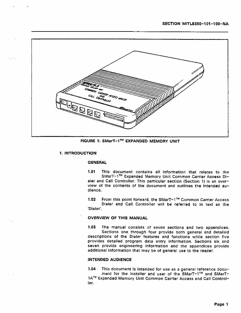
SECTION MITL8350-1 01-l OO-NA
FIGURE 1: SMarT-‘lTM EXPANDED MEMORY UNIT
1. INTRODUCTION
GENERAL
1.01 This document contains all information that relates to the SMarT-lTM Expanded Memory Unit Common Carrier Access Di-
aler and Call Controller. This particular section (Section 1) is an over- view of the contents of the document and outlines the intended au- dience.
1.02 From this point forward, the SMarT-lTM Common Carrier Access Dialer and Call Controller will be referred to in text as the
‘Dialer’.
OVERVIEW OF THIS MANUAL
1.03 The manual consists of seven sections and two appendices. Sections one through four provide both general and detailed
descriptions of the Dialer features and functions while section five provides detailed program data entry information. Sections six and seven provide engineering information and the appendices provide additional information that may be of general use to the reader.
INTENDED AUDIENCE
1.04 This document is intended for use as a general reference docu- ment for the installer and user of the SMarT-lTM and SMarT-
lATM Expanded Memory Unit Common Carrier Access and Call Control- ler.
Page 9

SECTiON MIITL8350-1 Ol-lOO-NA
HISTORY
1.05 This is the first issue of the SMarT-lTM Expanded Memory Unit Common Carrier Access Dialer and Call Controller General In-
formation Manual. The reason for issue was to supplement the General Information Manual with the Expanded Memory Unit and includes re- quirements of the present software level (Generics 19 and 29, Rev. 07 and later) of the Dialer.
2. GENERAL DESCRIPTION
2.01 The SMarT-lTM Expanded Memory Unit Common Carrier Access Dialer and Call Controller is a self-contained electronics unit
that provides all functions of the standard SMarT-lTM Dialer plus four times the amount of memory. The standard 2K of RAM Memory has been expanded to 8K. It also has the capability to assume the function of a sophisticated speed dialer for applications such as 800 Service Resale, special DISA, or l-800 service.
2.02 The SMarT-lTM Expanded Memory Unit Dialer provides the fol- lowing features and functions:
0
8
FCC Parts 15 and 88 compliance
Four Line capability for the 8350-654)
SMarT-I’” unit (MITEL P/N
0 Two Line capability for the 8350-652)
SMarT-lATM unit (MITEL P/N
SMDR Output
Versatile programming
Automatic Route Selection (ARS)
Up to 1,000 Speed Calls, depending on length of Speed Call
0 Installer-programmable l Customer-programmable
Tone to Pulse conversion
Pulse to Tone conversion
Each Speed Dial entry may contain its own unique account code
a SMDR indication of Speed Call and its related account code number
l In addition, the unit has the following convenience features:
0 Useable with CENTREX Lines a Useable behind a PBX/PABX a Hot Line operation 0 Multi-Tenant service.
2.03 Instead of operating in the dedicated Speed Dialer mode, the operational mode can be programmed to assume that of the
Page 2
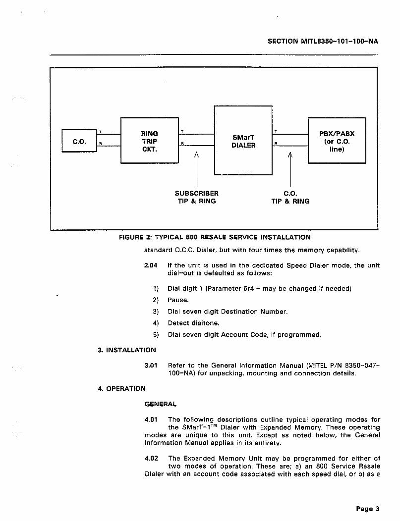
SECTION MITL8350-l Ol-l OO-NA
SUBSCRIBER TIP & RING
C.O. TIP & RING
FIGURE 2. TYPICAL 800 RESALE SERVICE INSTALLATION
standard O.C.C. Dialer, but with four times the memory capability.
2.04 If the unit is used in the dedicated Speed Dialer mode, the unit dial-out is defaulted as follows:
1) Dial digit 1 (Parameter 6r4 - may be changed if needed)
2) Pause.
3) Dial seven digit Destination Number.
4) Detect dialtone.
5) Dial seven digit Account Code, if programmed.
3. INSTALLATION
3.01 Refer to the General Information Manual (MITEL P/N 8350-047- 1 00-NA) for unpacking, mounting and connection details.
4. OPERATION
GENERAL
4.01 The following descriptions outline typical operating modes for the SMarT-lTM Dialer with Expanded Memory. These operating
modes are unique to this unit. Except as noted below, the General Information Manual applies in its entirety.
4.02 The Expanded Memory Unit may be programmed for either of two modes of operation. These are; a) an 800 Service Resale
Dialer with an account code associated with each speed dial, or b) as a
Page 3

SECflON MITE8350-I 91-1 00-NA
standard O.C.C. Dialer with enhanced search table quantity capabilities and capable of up to 1,000 speed calls (still with an account code associated with each speed dial, if desired).
.. “,, INlTlAblZlNG THE DlAbER : :
4.03 The Dialer is initialized in the same manner as the standard SMarT-lTM Dialer with the exception of the default command to
be given upon initialization completion. The procedure for initialization listed below is repeated from the General information Manual to re- duce cross referencing and to include the default command upon completion of initialization.
1) 2)
3)
4
5)
61
7)
Note:
4.04
1)
2)
Connect an earth ground to the Dialer.
Connect a DTMF telephone or butt set to the subscriber side Tip & Ring leads of the Dialer.
Connect a standard telephone line or network to the CO. side of the Dialer.
With the power to the Dialer disconnected, go off-hook
While holding down the * key on the DTMF set, connect the power to the Dialer. A DTMF tone should be audible in the handset receiver.
Continue to hold the * key for 10 seconds or more after apply- ing power to the Dialer.
Release the ++ key. The unit should respond immediately with a short tone from the handset receiver. If the tone is not heard, return to step 1 above and start over. The tone burst indicates that the Dialer is initialized and defaulted to its “standard” con- figuration. It also indicates that it is in the programming mode and awaiting a command.
If the Dialer is to be used as an 800 Service Resale Dialer, the user need not be concerned with further programming other than referenced for this use below. If the Dialer is to be used as a standard O.C.C. Dialer, then programming may be ac- complished by the use of any of the methods listed in the General Information Manual, Section 5.
Once the above listed procedure has been completed, the user has two options available. These are:
GO ON-HOOK: The Dialer is defaulted as a standard O.C.C. Dialer as noted in the General Information Manual. The only difference is that it is capable of up to 1,000 Speed Calls (with account codes). All of the programming information in the Gen- eral Information Manual applies to the Dialer in this configura- tion This configuration will also be assumed if a ‘903’ command is issued in the Program Mode.
DIAL ‘909’ ON THE DTMF S&T: This action defaults the Dialer to the Speed Dialer Mode (800 Service Resale Dialer with account
Page 4
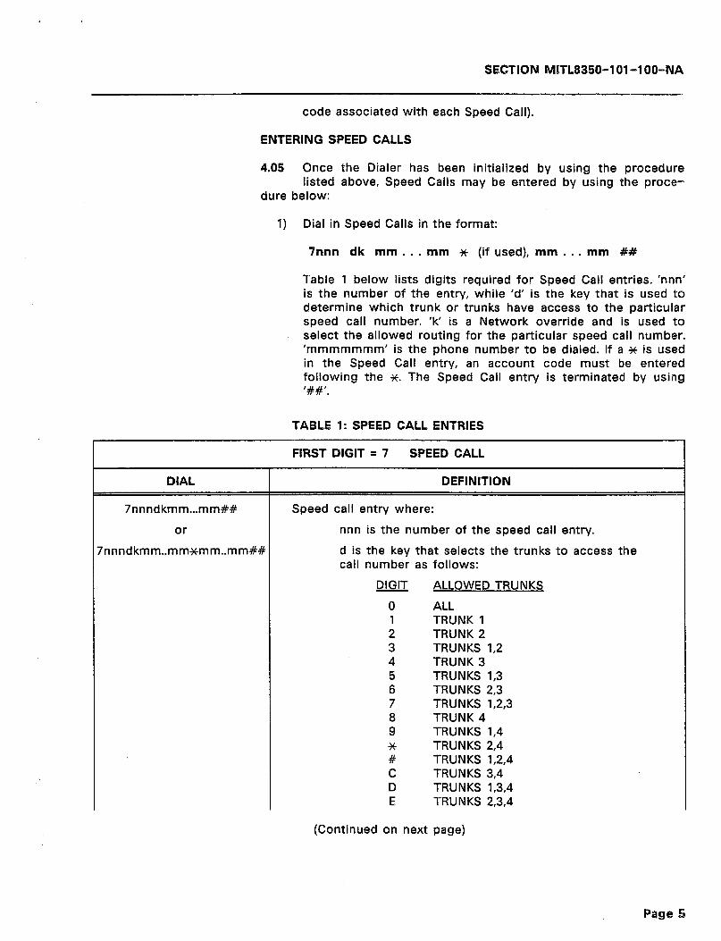
SECTION MITL8350-l Ol -lOO-NA
code associated with each Speed Call).
ENTERING SPEED CALLS
4.05 Once the Dialer has been initialized by using the procedure listed above, Speed Calls may be entered by using the proce-
dure below:
1) Dial in Speed Calls in the format:
Snnn dk mm.. , mm * (if used), mm . . . mm ##
Table 1 below lists digits required for Speed Call entries. ‘nnn’ is the number of the entry, while ‘d’ is the key that is used to determine which trunk or trunks have access to the particular speed call number. ‘k’ is a Network override and is used to select the allowed routing for the particular speed call number. ‘mmmmmmm’ is the phone number to be dialed. If a * is used in the Speed Call entry, an account code must be entered following the %. The Speed Call entry is terminated by using ‘##‘.
TABLE 4: SPEED CALL ENTRIES
DIAL
7nnndkmm...mm##
or
rnnndkmm..mm~mm..mm##
FIRST DIGIT = 7 SPEED CALL
DEFINITION
Speed call entry where:
nnn is the number of the speed call entry.
d is the key that selects the trunks to access the call number as follows:
DIGIT ALLOWED TRUNKS
0 ALL 1 TRUNK 1 2 TRUNK 2 3 TRUNKS 1,2 4 TRUNK 3 5 TRUNKS 1,3 6 TRUNKS 2,3 7 TRUNKS 1,2,3 8 TRUNK 4 9 TRUNKS 1,4 * TRUNKS 2,4 # TRUNKS 1,2,4 C TRUNKS 3,4 D TRUNKS 1,3,4 E TRUNKS 2,3,4
(Continued on next page)
Page 5

SECTION MlTL8350-101-l OO-NA
TABLE 1 Con’t: SPEED CALL ENTRIES
DIAL
FIRST DlGlT = 7 SPEED CALL
DEFINITION
NGTE: The C, D, and E entries above may be made from a terminal.
k is the network override:
0 - 3 Force on Route #0 - #3 4 - 7 Force on Route #Qa - 3a
8 Use search table 9 Dial immediate, no Route Xs (transparent).
mmmmmmm is the phone number. if a * is entered, the digits after the ++ are considered to be an ac- count code.
## is the end of Speed Call entry.
NBTE: See Search Table Action ‘#C” for limited access to Speed Call Programming.
Delete speed dial entry nnn. 7nnn##
After entering all Speed Calls, exit the programming mode by going On-Hook; or by dialing ‘999’ on the DTMF Handset or, if using a terminal, typing an ‘X’.
If it is necessary to re-enter the program mode, the default access codes are the same as those of a standard Dialer. They are: a) #OS from the DTMF Handset, or b) ### from a user Speed Call entry viewpoint, or c) Carriage Return (<CR>) from a terminal.
Data confirmation may be accomplished from the programming mode with the use of a terminal. The ‘902’ command will enter the data confirmation mode and allow the reading back of Speed Call entries (or any other parameter). The ‘907’ command is used to exit the data confirmation mode.
Table 2 below lists System Parameters that are present and contains a description of the programming entries required to invoke special functions. Commands 903, 904, 906, and 908 will affect calls in progress.
Page 6

SECPIBM MlTL8350-l Ol -lOO-NA
TABLE 2: SPECIAL FUNCTIONS AND COMMANDS
FIRST DIGIT = 9
903 904
906 907
908 909
980mmddhhmm
described above, the Dialer will display the data if program- ming method 1 is employed, or if using methods 2 or 3, the Dialer will wait for 0.5 seconds, then send the data out on the C.0 side in DTMF format. See General Information Man- ual, Section 5 for a description of programming met,hods 1,
Load O.C.C. default data - delete all non-default data. Clear all search tables (including defaults, primary and al-
Enter clone master mode. Return to normal programming mode from data confirmation
Enter tandem operation mode (ASCII - DTMF conversion). Default the Dialer to 800 Service Resale mode of operation with an account code associated with each Speed Call.
the internal clock where mm = month, dd = day, hh =
SPECIFIC DEFAULTS
4.06 The paragraphs that follow list specific defaults and values for the Expanded Memory Dialer. Any parameters that are not listed
appear in the General Information Manual. They are also the same defaults as for the standard SMarT-1 TM Dialer and are identical for either modes of operation of the Expanded Memory Dialer. For more information on these defaults, refer to the General Information Manual, Section 5.
903 Default Command - Standard O.C.C. Dialer
4.07 All defaults are unchanged from the standard SMarT-lTM unit defaults. Refer to the General Information Manual, Section 5, for
a complete listing. Also refer to Table 4 of this manual for Speed Call and Account Code enhancements that are provided in the Expanded Memory unit under the 903 default.
909 Default Command - Speed Dialer Mode
4.08 In the Speed Dialer Mode, the following defaults are present:
1) It is not necessary to enter the ‘523 8’ parameter that com- mands the Dialer to wait for dialed digits and use the search tables. This parameter is already activated for all trunks.
2) The intended and recommended Route for Speed Calls is ‘Route
Page 7
SECTION MiTL8350-l Ol-l OO-NA
3)
4)
51
6)
7)
3’. This Route is the least likely to be used route for C.C.C. activity (should it be desired) and allows Route 0 to remain as the default route. If this parameter is used in this manner and it is decided to add call routing capabilities at a later date along with the Speed Call function, it may be programmed as with the standard Dialer without disturbing Speed Call programming.
The system default Program Access Code is #Cl*. The Sub- scriber (User) Speed Call Program Access Code is ###. All trunks have access to all subscriber entered Speed Cal,ls. These subscriber entered Speed Calls are forced to dial out on Route 3.
Speed Call triggers are any combination of three digits ranging from ‘000’ to ‘999’ (1,000 possible combinations). As defaulted, no * or similar prefix need be dialed to trigger a Speed Call. All digits entered (or dialed) are considered as a part of the Speed Call trigger (location) up to a maximum of three digits.
There are no Q.C.C. Search Tables present. The only Search Tables present are those for DTMF Program Access and the Speed Call action
The Call Recording output will indicate “SC.” for Speed Call, along with the destination number dialed, and the account code, if entered.
The Speed Call programming format from the system #OS ac- cess is:
7nnn dk mm.. _ mm## (If ## is not entered. interdigit time-out will complete the entry) while the subscriber Speed Call programming format from the ### access is:
nnn dk mm.. _ mm## (or timeout)
(if ## is not entered, interdigit time-out will complete the entry) where all trunks are allowed access and the Speed Calls are forced out on Route 3 (equivalent to dk=03).
Specific 909 Command Defaults
4.09 Table 3 below lists the specific defaults for the 909 Command that causes the unit to act as a sophisticated Speed Dialer (800
Service Resale Dialer). The letter ‘x’ or ‘r’ in the code, represents a single user selectable character for entry to select a specific trunk or route number for the parameter. The letter ‘t’ represents a digit for entry. For more information on specific uses of these letters, refer to the specific command description in the General Information Manual, Section 5 and Table 8.
Page 8
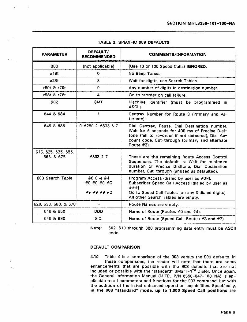
SECTION MITL8350-l Ol-l OO-NA
TABLE 3: SPECIFIC 909 DEFAULTS
PARAMETER
r50t & r70t
r58t & r78t
602
644 & 684
645 & 685
;15, 625, 635, 655, 665, & 675
803 Search Table
20, 630, 660, & 670
610 & 650
640 & 680
DEFAULT/ RECOMMENDED
(not applicable)
8
SMT
9 #250 2 #833 5 7
#803 2 7 These are the remaining Route Access Control
DDD
S.C.
Note: 602, 610 through 680 programming data entry must be ASCll code.
DEFAULT COMPARISON
4.10 Table 4 is a comparison of the 903 versus the 909 defaults. In these comparisons, the reader will note that there are some
enhancements that are possible with the 903 defaults that are not included or possible with the “standard” SMarT-lTM Dialer. Once again, the General Information Manual (MITEL P/N 8350-047-lOO-NA) is ap- plicable to all parameters and functions for the 903 command, but with the addition of the listed enhanced operation capabilities. Specifically, in the 903 “standard” mode, up to 1,000 Speed Call positions are
Page B
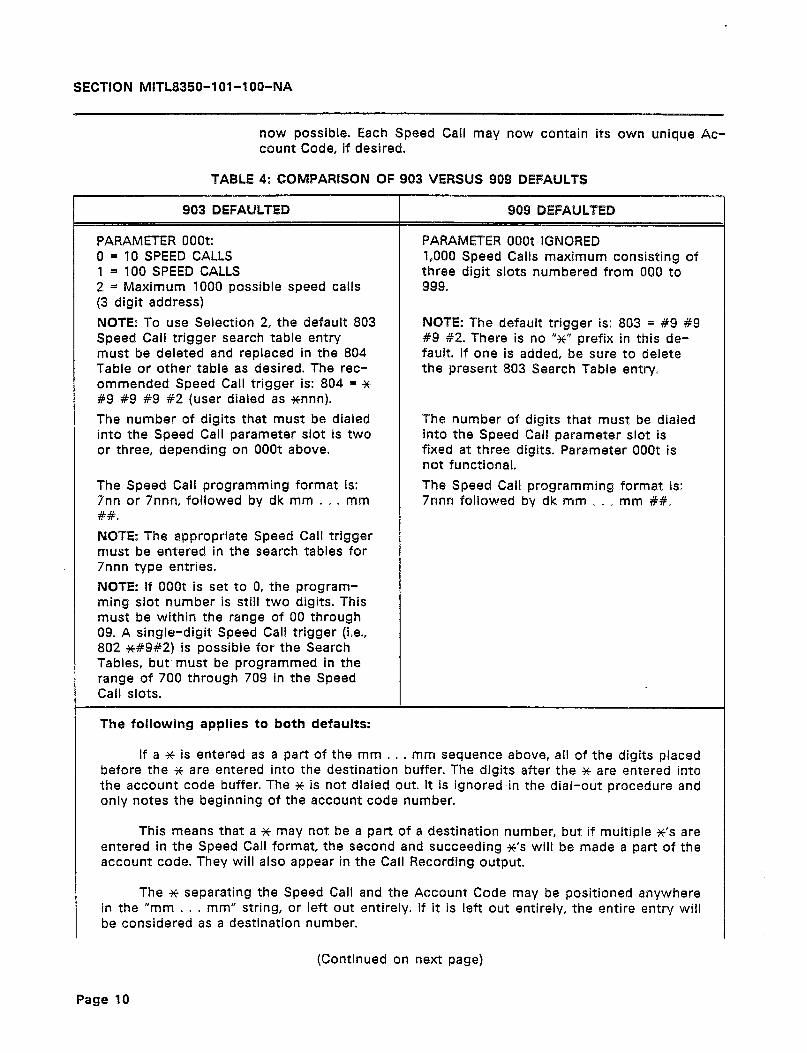
SECTION MITL8350-l Ol-l OO-NA
now possible. Each Speed Call may now contain its own unique Ac- count Code, if desired.
TABLE 4: COMPARISON OF 903 VERSUS 909 DEFAULTS
903 DEFAULTED
PARAMETER OOOt: 0 = 10 SPEED CALLS 1 = 100 SPEED CALLS 2 = Maximum 1000 possible speed calls (3 digit address)
NOTE: To use Selection 2, the default 803 Speed Call trigger search table entry must be deleted and replaced in the 804 Table or other table as desired. The rec- ommended Speed Call trigger is: 804 = $6 #9 #9 #9 #2 (user dialed as *nnn).
The number of digits that must be dialed into the Speed Call parameter slot is two or three, depending on OOOt above.
The Speed Call programming format is: 7nn or 7nnn, followed by dk mm . o . mm ##.
NOTE: The appropriate Speed Call trigger must be entered in the search tables for 7nnn type entries.
NOTE: If OOOt is set to 0, the program- ming slot number is still two digits. This must be within the range of 00 through 09. A single-digit Speed Call trigger (i.e., 802 *#9#2) is possible for the Search Tables, but. must be programmed in the range of 700 through 709 in the Speed Call slots.
The foilowing applies to both defaults:
909 DEFAULTED
PARAMETER OOOt IGNORED 1,000 Speed Calls maximum consisting of three digit slots numbered from 000 to 999.
NOTE: The default trigger is: 803 = #9 +9 #9 82. There is no “So prefix in this de- fault. If one is added, be sure to delete the present 803 Search Table entry.
The number of digits that must be dialed into the Speed Call parameter slot is fixed at three digits. Parameter OOOP is not functional.
The Speed Call programming format is: 7nnn followed by dk mm ~ ~ * mm ##.
If a * is entered as a part of the mm . . . mm sequence above, all of the digits placed before the ic are entered into the destination buffer. The digits after the * are entered into the account code buffer. The ++ is not dialed out. It is ignored-in the dial-out procedure and only notes the beginning of the account code number.
This means that a * may not be a part of a destination number, but if multiple s’s are entered in the Speed Call format, the second and succeeding N’S will be made a part of the account code. They will also appear in the Call Recording output
The * separating the Speed Call and the Account Code may be positioned anywhere in the “mm . . . mm” string, or left out entirely. If it is left out entirely, the entire entry will be considered as a destination number.
(Continued on next page)

SECTION MITL8350-l Ol-l OO-NA
TABLE 4 Con’t: COMPARISON OF 903 VERSUS 909 DEFAULTS
903 DEFAULTED 909 DEFAULTED
The maximum length of the field is 30 characters (29 digits and a XC). The maximum length of a Speed Call or Account Code field alone within the 30-character limit is 23 digits.
In the 903 Mode, the 6r5 Access Control Strings, of course, must be programmed to dial out the Account Codes, if desired.
Speed Dialing may be done on any route in either default format. Note that Route #3 is the recommended route for the 909 Speed Dialer Mode.
The User Speed Call programming access code is ###. There is no change. In other words, all trunks are allowed access and speed calls go to search tables (dk = 08).
The User Speed Call programming access code is ###. Speed Calls are routed to Route #3. All trunks are allowed access (dk = 03).
1
Note: For installations not capable of transmitting the “#” sign to the dialer, the program access may be changed to any desired series of digits via search table programming. Waiting for expiration of the interdigit time-out will automatically com- plete the entry, thus avoiding the ## terminating entry.
5. PROGRAMMING EXAMPLES AND USE
“909” SOPHISTICATED SPEED DIALER PROGRAMMING
5.01 The following paragraphs show examples of specific program- ming for Speed Calls for both the system programming and the
User programming viewpoints. It should be noted that the “0” portion of the “03” strings below may be chosen differently, if desired, to allow differing combinations of trunks to have access to the Speed Call (see Table 1 ‘dk’). The “3” portion of the “03” string, however, should remain “3” each time. This forces all Speed Calls to Route #3. Using other routes may require additional programming (refer to the General In- formation Manual).
#Ox SYSTEM PROGRAM ACCESS
1) Go Off-Hook. 2) Dial #ON. 3) Wait for the confirming tone. 4) Dial 909. This defaults the Dialer to the sophisticated Speed
Dialer data base. 5) The examples that follow on the next page show entries which
will not use Account Codes:
Page 11
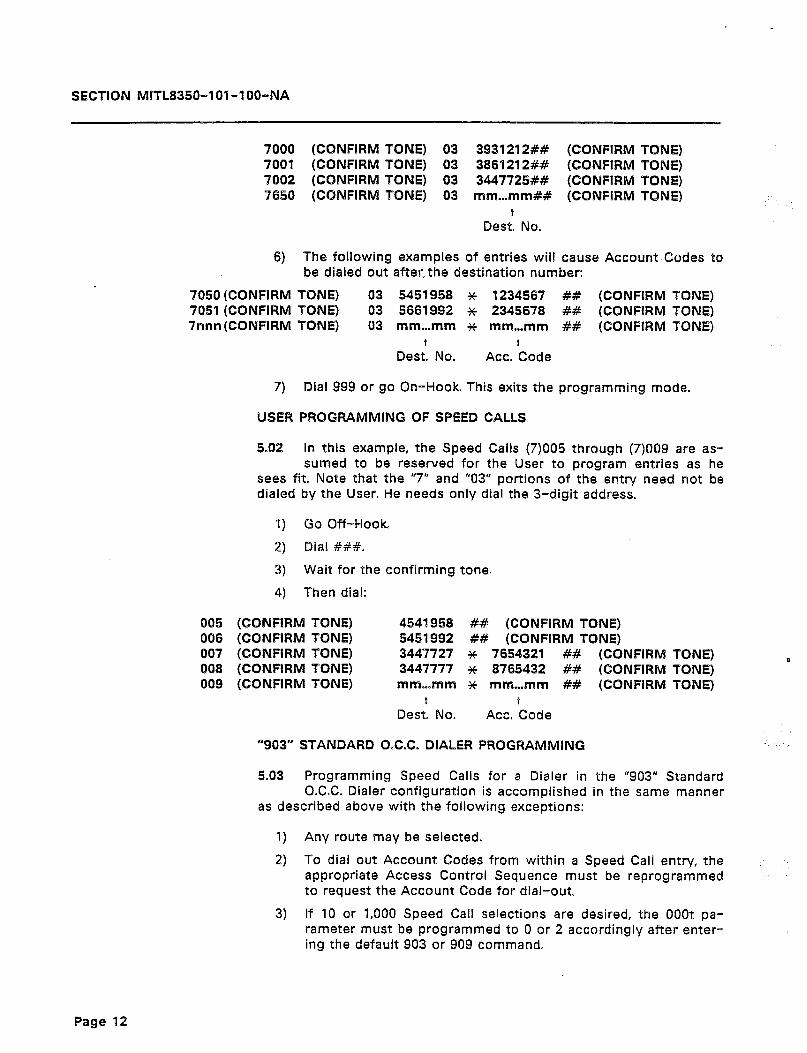
SECTION MITL8350-101-l OO-NA
7000 (CONFIRM TONE) 03 3931212## (CONFIRM TONE) 7001 (CONFIRM TONE) 03 3861212## (CONFIRM TONE) 7002 (CONFIRM TONE) 03 3447725&Y (CONFIRM TONE) 7660 (CONFIRM TONE) 03 mrn...mm## (CONFIRM TONE)
Des: No.
6) The following examples of entries will cause Account Codes to be dialed out after. the destination number:
7050 (CONFIRM TONE) 7051 (CONFIRM TONE) 7nnn (CONFIRM TONE)
03 5459958 * 1234567 ## (CONFIRM TONE) 03 5661992 * 2345678 ## (CONFIRM TONE) 03 mm...mm ++ mm...mm ## (CONFIRM TONE)
Des:. No. Act. ‘Code
7) Dial 999 or go On-Hook. This exits the programming mode.
C%SER PROGRAMMING OF SPEED CALLS
5.02 In this example, the Speed Calls (7)OQ5 through (7)QO9 are as- sumed to be reserved for the User to program entries as he
sees fit. Note that the “7” and “03” portions of the entry need not be dialed by the User. He needs only dial the 3-digit address.
I) Go Off-Hook.
2) Dial ###.
3) Wait for the confirming tone.
4) Then dial:
005 (CONFIRM TONE) 006 (CONFIRM TONE) 007 (CONFIRM TONE) 008 (CONFIRM TONE) 009 (CONFIRM TONE)
“903” STANDARD O.C.C. DIALER PROGRAMMING
4541956 ## (CONFIRM TONE) 5451992 ## (CONFIRM TONE) 3447727 * 7654321 ## (CONFIRM 3447777 ++ 6765432 ## (CONFIRM mm...mm * mm...mm ## (CONFIRM
Des: No. t
Ace. Code
TONE) 0 TONE) TONE)
5.03 Programming Speed Calls for a Dialer in the “903” Standard O.C.C. Dialer configuration is accomplished in the same manner
as described above with the following exceptions:
1) Any route may be selected.
2) To dial out Account Codes from within a Speed Call entry, the appropriate Access Control Sequence must be reprogrammed to request the Account Code for dial-out.
3) If 10 or 1,000 Speed Call selections are desired, the OfJOt pa- rameter must be programmed to 0 or 2 accordingly after enter- ing the default 903 or 909 command.
Page 12
SECTION MlTL8350-l Ol-l OO-NA
4) When programming from the User Program Access Code (###), all Speed Calls programmed are routed through the Search Tables (dk = 08).
DIALING SPEED CALLS
5.04 Once the Dialer has been installed and depending upon the type of programming, the user may dial Speed Calls. The method to
access Speed Calls differs depending on unit usage. If 909 Default programming was used, there are no special instructions required to dial a Speed Call. Simply dial the three-digit number of the desired Speed Call and all else is transparent to the user. If the unit has been programmed with the 903 Default, there will be a default Speed Call “trigger” character. This trigger exists in the 803 Search Table. If pa- rameter OOOt is either 0 or 1 (10 or 100 Speed Calls), the trigger exists in the 803 Search Table and is, by default, %. If parameter OOOt is 2 (1,000 Speed Calls), the trigger in table 803 must be deleted and replaced in table 804, for example (by programming). Once again, it is recommended that the x character be used as the trigger. In the case of the 903 default, to access a Speed Call (default programming), simply dial *nn to access a given Speed Call, where ‘nn’ is from 00-99 for a specific stored Speed Call.
Note: For more details, refer to the General Information Manual.
5. SPEED CALL VERSUS SCREENING CAPABILITIES
6.01 There are several ways in which to calculate the maximum quantity of Speed Calls and Screen Quantities capable of being
programmed into the Dialer. Since both Speed Call and Search Table screens may be of varying length, depending upon the application, graphs are not practical. Some simple methods of determining the capabilities are possible.
Ground Rules
6.02 There are two basic ground rules that are applicable. These are:
1) After a 909 default command, there are ‘l5,OOO spaces in mem- ory left for data.
2) After a 903 default command, there are 14,500 spaces in mem- ory left for data.
Methods
6.03 The simplest method used to determine if the intended data base will fit into memory (almost all will), is to calculate the
space required by the data. Then compare this space to the space available according to the following formulae:
1) A search table entry occupies a number of spaces equal to the length of the template plus the action digit(s). An 804 Search Table entry such as ‘804 1315 0’, for example, is four digits plus
Page 13
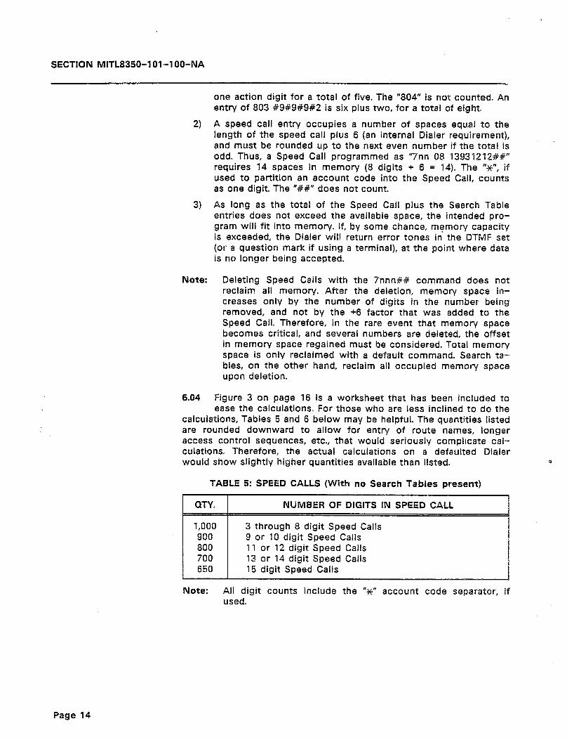
SECTION MITL8350-I Ol-l OO-NA
one action digit for a total of five. The “804” is not counted. An entry of 803 #9#9#9#2 is six plus two, for a total of eight.
2) A speed call entry occupies a number of spaces equal to the length of the speed call plus 6 (an internal Dialer requirement), and must be rounded up to the next ewen number if the total is odd. Thus, a Speed Call programmed as “7nn 08 13931212##” requires 14 spaces in memory (8 digits + 6 = 14). The W’, if used to partition an account code into the Speed Call, counts as one digit. The “#I” does not count.
3) As long as the total of the Speed Call plus the Search Table entries does not exceed the available space, the intended pro- gram will fit into memory. If, by some chance, memory capacity is exceeded, the Dialer will return error tones in the DTMF set (or a question mark if using a terminal), at the point where data is no longer being accepted.
Note: Deleting Speed Calls with the Snnn## command does not reclaim all memory. After the deletion, memory space in- creases only by the number of digits in the number being removed, and not by the +6 factor that was added to the Speed Call. Therefore, in the rare event that memory space becomes critical, and several numbers are deleted, the offset in memory space regained must be considered. Total memory space is only reclaimed with a default command. Search ta- bles, on the other hand, reclaim all occupied memory space upon deletion.
6.04 Figure 3 on page 16 is a worksheet that has been included to ease the calculations. For those who are less inclined to do the
calculations, Tables 5 and 6 below may be helpful. The quantities listed are rounded downward to allow for entry of route names, longer access control sequences, etc., that would seriously complicate cal- culations. Therefore, the actual calculations on a defaulted Dialer would show slightly higher quantities available than listed.
TABLE 5: SPEED CALLS (With no Search Tabies present)
3 through 8 digit Speed Calls 9 or 10 digit Speed Calls 11 or 12 digit Speed Calls
Note: All digit counts include the “N” account code separator, if used.
P
Page 14
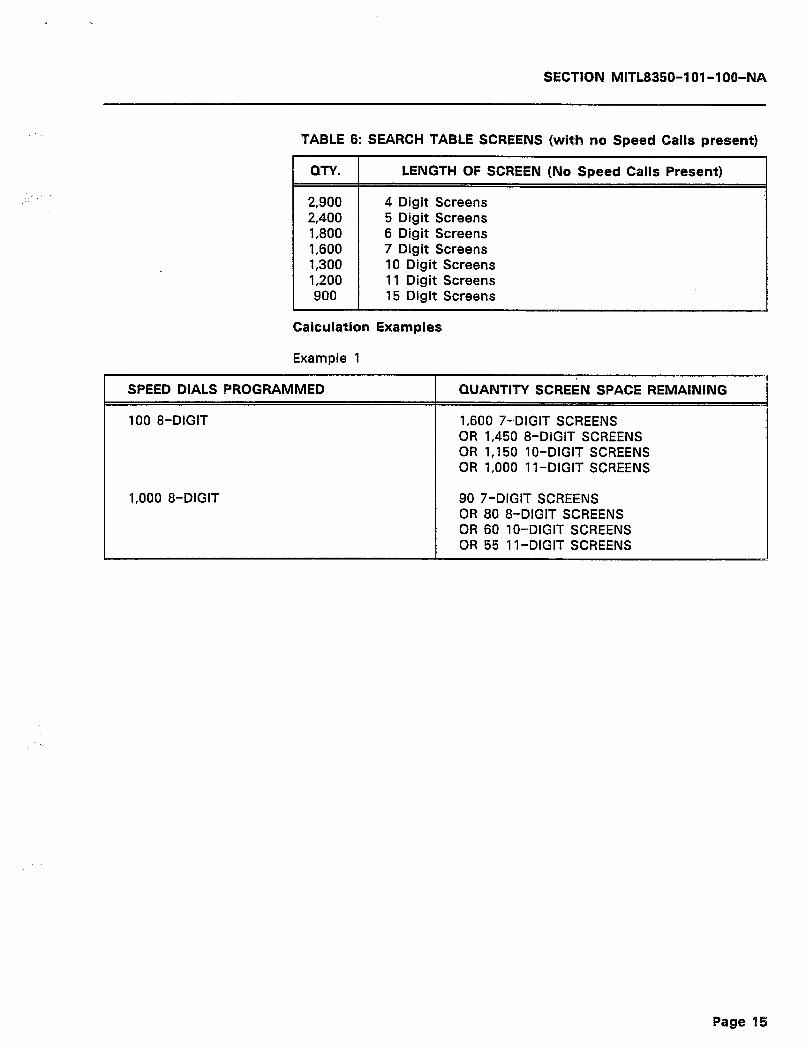
SECTION MITL8350-101-100-NA
TABLE 6: SEARCH TABLE SCREENS (with no Speed Calls present)
QTY.
2,900 2,400 1,800 1,600 1,300 1,200 900
LENGTH OF SCREEN (No Speed Calls Present)
4 Digit Screens 5 Digit Screens 6 Digit Screens 7 Digit Screens 10 Digit Screens 11 Digit Screens 15 Digit Screens
Calculation Examples
Example 1
100 8-DIGIT 1,600 7-DIGIT SCREENS OR 1,450 8-DIGIT SCREENS OR 1,150 lo-DIGIT SCREENS OR 1,000 ll-DIGIT SCREENS
1,000 8-DIGIT 90 ‘/-DIGIT SCREENS OR 80 8-DIGIT SCREENS
Page 1%
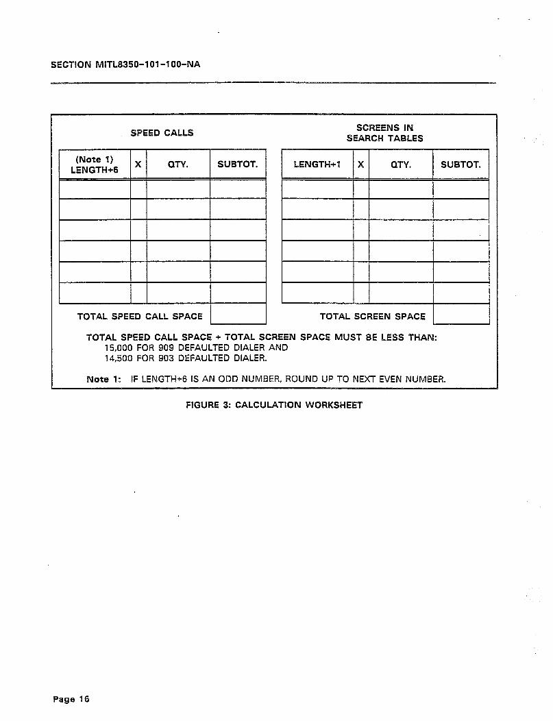
SECTION MITL8350-lOl-l OO-NA
SPEED CALLS SCREENS IN
SEARCH TABLES
TOTAL SPEED CALL SPACE TOTAL SCREEN SPACE 1 ]
TOTAL SPEED CALL SPACE + TOTAL SCREEN SPACE MUST 8E LESS THAN: 15,000 FOR 909 DEFAULTED DIALER AND 14,500 FOR 903 DEFAULTED DIALER.
Note a: IF LENGTH+6 IS AN ODD NUMBER, ROUND UP TO NEXT EVEN NUMBER.
FIGURE 3: CALCULATION WORKSHEET
Page 16
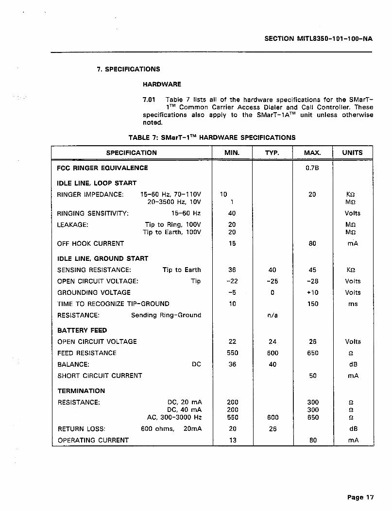
SECTION MlTL8350-l Ol-l OO-NA
7. SPECIFICATIONS
HARDWARE
7.01 Table 7 lists all of the hardware specifications for the SMarT- lTM Common Carrier Access Dialer and Call Controller. These
specifications also apply to the SMarT-‘lATM unit unless otherwise noted.
TABLE 7: SMarT-lTM HARDWARE SPECIFICATIONS
SPECIFICATlON
FCC RINGER EQUIVALENCE
IDLE LINE, LOOP START
RINGER IMPEDANCE: 15-60 Hz, 70-‘llOV 20-3500 Hz, 1OV
RINGING SENSITIVITY: 15-60 Hz
LEAKAGE: Tip to Ring, 1OOV Tip to Earth, 1OOV
OFF HOOK CURRENT
lDLE LINE, GROUND START
SENSING RESISTANCE: Tip to Earth
OPEN CIRCUIT VOLTAGE: Tip
GROUNDING VOLTAGE
TIME TO RECOGNIZE TIP-GROUND
RESISTANCE: Sending Ring-Ground
BATTERY FEED
OPEN CIRCUIT VOLTAGE
FEED RESISTANCE
BALANCE: DC
SHORT CIRCUIT CURRENT
TERMINATION
RESISTANCE: DC, 20 mA DC, 40 mA
AC, 300-3000 Hz
RETURN LOSS: 600 ohms, 20mA
OPERATING CURRENT
MIN.
10 1
40
20 20
15
36
-22
-5
‘10
22
550
36
200 200 550
20
13
TYP.
40
-25
0
n/a
24
600
40
600
26
MAX.
0.78
20
80
45
-28
+I0
150
26
650
50
300 300 650
80
UNlTS
K& MSt
Volts
M& Ma
m A
K&
Volts
Volts
ms
Volts
&
dB
mA
fi Q fi
dB
mA
Page 97

SECTION MITL8350-101-l OO-NA
TABLE 7 CON’T: SMasT-1 TM HARDWARE SPEClFlCATlONS
CO SIDE FEED: Gain 300 Hz
INTERNAL FEED:
DTMF RECEIVER
LEVEL
LEVEL DIFFERENCE
FREQ. To receive To not receive
DURATlON
TIME BETWEEN TONES
ROTARY RECEIVER
MAKE IMPEDANCE
MAKE DURATION
BREAK IMPEDANCE
BREAK DURATION
RATE
DTMF SENDER
LEVEL
FREQUENCY
DURATION (Programmable)
ROTARY SENDER
TIMING (Programmable)
TIMING (At 60140):
RATE (At 60/40)
INTERDIGIT PAUSE (Programmable)
OPERATING RANGE
TEMPERATURE
HUMIDITY
ALLOWABLE VOLTAGE: connected to any
-/- With reference to 600~ Termination.
Page 18

SECTION MITL8350-lOl -l OO-NA
RS-232 PORT
9.02 Table 8 below contains the specifications for the SMarT-lTM Common Carrier Access Dialer and Call Controller RS-232 Aux-
iliary Port. This port may be used for programming or for SMDR output.
TABLE 8: RS-232 PORT SPECIFICATIONS
BAUD RATE:
PARITY:
BITS PER CHARACTER:
BIT EIGHT SENSE:
MODE:
300 to 19200 Baud programmable; de-
Eight bits per character with one stop
ELECTRICAL/MECHANICAL
7.03 Table 9 contains the Electrical and Mechanical specifications for the SMarT-lTM Common Carrier Access Dialer and Call Control-
ler. These specifications also apply to the SMarT-lATM unit unless otherwise noted.
4.04 This section does not contain all of the specifications for the Dialer. Other specifications may be added.
TABLE 9: ELECTRICAL/MECHANICAL SPECIFICATIONS
PARAMETER I SPECIFICATION
DIMENSIONS:
WEIGHT: Dialer
Power Supply
MOUNTING:
POWER:
Range:
CONNECTIONS:
7.625” (19.37cm) Wide X 10.625” (26.99cm) H X 1.375” (3.49cm) D
2 Ibs (0.907 kg)
1 lb (0.453 kg) (Approximately)
Wall Mount with Supplied Bracket
115 Volts AC, 60 Hz 8 300 mA
103.5 to 126.5 VAC
Standard RJ31X Network Connections
Page 19
SECTION MITL8350-lOl-l OO-NA
7.05 The specifications in the Tables above are subject to change without notice. The inclusion of ‘n/a’ for a specific parameter
means that the specification is not available at the time of this pub- lication.
r
Page 20
SECTIBN MITL8350-101-l OO-NA
APPENDIX A
FCC INTERCONNECTION REQUIREMENTS
General
Al.01 This equipment has been approved by the Federal Communica- tions Commission (FCC) as not being harmful to the telephone
network when connected directly to the telephone lines through the standard connection cabling provided with the unit. This section is applicable to telephone interconnection in the United States.
Al.02 Prior to the interconnection of this equipment, the local tele- phone company is to be notified; inform the company that you
have FCC-registered equipment that you wish to connect to their trunks. Give them the following information:
e The telephone number of the line that will connect to the unit.
0 The equipment being connected is a MITEL DATACOM INC. model SMarT-lTM or model SMarT-IA Common Carrier Access Dialer and Call Controller.
8 The FCC Registration Number for the SMarT-lTM or SMarT-lATM is EMP 85B-14558-LR-E
@ The FCC Ringer Equivalence Number (REN) which is 0.7B.
e The Connector Jacks required are RJ31X.
CONNECTION LIMITATIONS
Al.03 Due to the FCC Part 68 Rule, no connection can be made to party lines and to coin telephone service. This unit is designed
to be used on standard-device telephone lines. If there are any ques- tions about the telephone line, such as how many pieces of equipment may be connected to it, the telephone company will provide this information upon request.
NETWORK CHANGES
Al.04 The telephone company may make changes to it’s communica- tion service; such changes may include the change of trunk
circuits, changes in the operational characteristics of its trunks, etc. Before doing this, however, the company shall provide official notifica- tion, so that the operation of the Dialer service will not be interrupted.
MAINTENANCE LIMITATIONS
Al.05 This equipment has been registered with the FCC for direct connection to the telephone network. Under the FCC program,
the user is restricted from making any changes or repairs and from performing any maintenance operations other than those specifically included in this document.
Page A-l
.
SECTKIN MITL8350-lOl-l OO-NA
Al -06 There are no user repairable parts within the unit. It is sealed against user maintenance. If opened, all warranties are voided.
Al 007 No cabling or wiring changes within the unit are permitted by ‘:..‘...:’ the user. Plug-ended cables, es detailed in this document, ara used for all external connections between the unit and the to be
telephone company interface jack
Al.08 Power supply components and cabling is only to be changed or maintained by MITEL DATACOM INC. or by an authorized agent
of MITEL DATACOM INC.
TROUBLE CORRECTIONS
Al.09 For all malfunctions, appropriate field service is provided by MITE% DATACOM INC. or its authorized agents
DISCONNECTION
Al.10 If it is ever decided to permanently disconnect the SMarT-lfM or SMarT-lATM Dialer from the present line, please notify the
telephone company of this change.
Page A-2

SECTlON MlfL8350-l Ol-lOO-NA
APPENDIX B OVERALL INDEX
CONTENTS PAGE
APPENDIX A CONNECTION LIMITATIONS CONNECTOR JACKS DISCONNECTION FCC INTERCONNECTION REQUIREMENTS FCC REGISTRATION NUMBER MAINTENANCE LIMITATIONS NETWORK CHANGES RINGER EQUIVALENCE NUMBER. TROUBLE CORRECTIONS
APPENDIX B OVERALL INDEX
CALCULATION EXAMPLES SEE SPEED CALL VERSUS SCREENING CAPABILITIES
CALCULATION METHODS SEE SPEED CALL VERSUS SCREENING CAPABILITIES
CALCULATION WORKSHEET SEE SPEED CALL VERSUS SCREENING CAPABILITIES
CONNECTION LIMITATIONS SEE APPENDIX A
CONNECTOR JACKS SEE APPENDIX A
CONVENIENCE FEATURES SEE GENERAL DESCRIPTION
DATA CONFIRMATION SEE ENTERING SPEED CALLS
DEDICATED SPEED DIALER MODE DEFAULT
DEFAULT COMPARISON SEE OPERATION SEE TABLE4 .._.. SEE TABLE 4
DESCRIPTION SEE GENERAL DESCRlmlON
DIALING SPEED CALLS SEE PROGRAMMING EXAMPLES AND USE
DISCONNECTION SEE APPENDIX A
ELECTRICAL SPECIFICATIONS SEE SPECIFICATIONS SEE TABLE 9
ELECTRICAL/MECHANICAL SEE SPECIFICATIONS
ELECTRICAL/MECHANICAL SPECIFICATIONS SEE TABLE 9 . . . . . . .
ENTERING DATA SPEED CALL ENTRIES
ENTERING SPEED CALLS DATA CONFIRMATION EXIT PROGRAMMING
FORMAT RE-ENTER PROGRAM MODE RE-ORDERTONE .._ .._.._
SEE OPERATION SYSTEM PARAMETERS
EXIT PROGRAMMING SEE ENTERING SPEED CALLS
FCC INTERCONNECTION REQUIREMENTS GENERAL SEE APPENDIX A
FCC REGISTRATION NUMBER SEE APPENDIX A
A-l A-l A-2 A-l A-l A-l A-l A-l A-2
B-l
15
13
16
A-l
A-l
2
6
2
9 10 11
2
13
A-2 GENERAL HISTORY INTENDED AUDIENCE OVERVIEW
19 19
19 JACKS
SEE APPENDIX A A-l
19
5
6 6
5 6 7
5 6
MAINTENANCE LIMITATIONS SEE APPENDIX A
MAXIMUM MEMORY SPACE (903 DEFAULT) SEE GROUND RULES
MAXIMUM MEMORY SPACE (909 DEFAULT) SEE GROUND RULES
MECHANICAL SPECIFICATIONS SEE SPECIFICATIONS SEE TABLE 9
. ..6 NETWORK CHANGES
1 ‘d-1
OPERATING MODES SEE OPERATION
OPERATION A-l DEFAULT COMPARISON
CONTENTS PAGE
FEATURES SEE GENERAL DESCRIPTION
FUNCTIONS SEE GENERAL DESCRIPTION .
GENERAL SEE INTRODUCTION
GENERAL DESCRIPTION CONVENIENCE FEATURES DESCRIPTION __._.. _, _._ .__ FEATURES I.__., ., . .._..._ ,., FUNCTIONS _...................
GENERAL OPERATION SEE OPERATION .
GROUND RULES SEE SPEED CALL VERSUS SCREENING CAPABILITIES
HARDWARE
SEE SPECIFICATIONS HARDWARE SPECIFICATIONS
SEE SPECIFICATIONS SEE TABLE 7 SEE TABLE 7 SMART-l HARDWARE SPECIFICATIONS
HISTORY SEE INTRODUCTION
INITIALI2ATION PROCEDURE SEE INITIALIZING THE DIALER
INITIALIZING THE DIALER SEE OPERATION
INSTALLATION
DESCRIPTION INSTALLATION DESCRIPTION
SEE INSTALLATION INTENDED AUDIENCE
SEE INTRODUCTION INTRODUCTION
SEE APPENDIX A A-l
2
2
. ..l
17
17 17 16 17
4
4
3
3
1
1 2 1 1
A-l
13
13
19 19
3
9
Page B-9
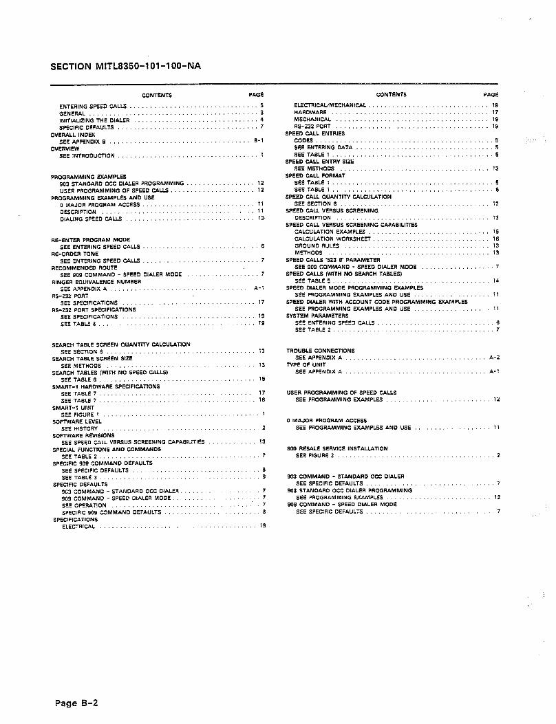
SECTION MITE8350-l Ol-l OO-NA
CONTENTS PAGE
ENTERING SPEED CALLS ................................ 5
GENERAL .......................................... 3 INlTlALlZlNG THE DIALER ............................... 4 SPfClFlC DEFAULTS ................................... 7
0VEfbU.L INDEX SEE APPENDIX S ................................... f-l
OVERVIEW SEElNtROOUCTlON ................................... 1
PROGFIAMMING EXAMPLES 903 STANDARD OCC DIALER PROGRAMMING ................. 12 USER PROGRAMMING OF SPEED CALLS. .................... 12
PROGRAMMING fXAMPLfS AND USE 0 MAJOR PROGRAM ACCESS ...................... ..... 11 q fSCRlPTlON ...................................... 11 DIALING SPEED CALLS ................................ 13.
%-ENTER PROGRAM MODE SEE ENTERING SPEED CALLS .......................... 6
RE-OROER TONE SEE ENTERING SPEED C4LLS ............................. 7
RECOMMENDED ROUTE SEE 909 COMMAND - SPEED DIALER MODE ................ 7
RINGER EQUIVALENCE NUMBER SEEAPPENQIXA ................................... A-l
RS-232 PORT SEE SPECIFICATIONS ... ............................. 17
RS-232 PORT SPECIFICATIONS SEE SPECIFICATIONS ................................. 19
SEE TABLE 8 ............................. ......... 19
SfARCH TABLE SCREEN QUANTITY CALCULATION SEf SEtTION 6 ..................................... 13
SfARCH TAELE SCREEN SIZE SEE MfTHQOS .................................... 13
SfARCH TASLfS (WITH NO SPEED CALLS) SEETABLES ....................................... 15
SMART-P HARDWARE SPECIFICATIONS SEETABLf 7 ....................................... 17 SEE TAELE 7 ....................................... 18
SMART-l UNIT SEE FIGURE1 ....................................... 1
SOFTWARE LNEL SEE HISTORY ....................................... 2
SOFTWARE RMSIONS SEE SPEED CALL VERSUS SCREENING CAPABILITIES ............ 13
SPECIAL FUNCTIONS AND COMMANDS SfETA9LE 2 ........................................ 7
SPECIFIC 909 COMMAND DEFAULTS SEE SPECIFIC DEFAULTS ................................ 8 SEETABLE 3.. ...................................... 9
SPECIFIC DEFAULTS 903 COMMAND - STANDARD OCC DIALER. ................ 7 909 COMMAND - SPEED DIALER MODE. ................... 7 SEE OPERATION ..................................... 7
SPECIFIC 909 COMMAND DEFAULTS ........................ 8
SPECIFICATIONS ELECTRICAL ..................................... 19
CONTENTS
ELfCTRlCAL/MECHANlCAL .......................... HARDWARE ................................... MECHANICAL .................................. RS-232 PORT ..................................
SPEED CALL ENTRIES CDDfS ....................................... SEE ENTERING DATA ............................. SEE TABLE1 ...................................
SPEED CALL ENTRY SIZE SEE MfTHOOS .................................
SPEED CALL FORMAT SEETABLE 1 ................................... SEETABLE 1 ...................................
SPEED CALL QUANTITY CALCULATION SEE SECTION 6 .................................
SPEED CALL VERSUS SCREENING OfSCRlFTlON ..................................
SPEED CALL VERSUS SCREENING CAPABILITIES CALCULATION WAMPLfS ......................... CALCULATION WORKSHEET ......................... GROUND RULf.5 ................................ MfTHOOS ....................................
SPCED CALLS ‘523 8’ PARAMETER SEE 909 COMMAND - SPEED DIALER MODE .............
SPEED CALLS IWITH NO SEARCH TABLES) SEE TASLE 5 ...................................
SPEED DIALER MODE PROGFIAMMING EXAMPLES SEE PROGRAMMING fXAMPLfS AN0 US& ...............
SPEED DIALER WITH ACCOUNT CODE PROGRAMMING D(BMPLfS SEE PROGRAMMING fXAMPLfS AND USE ..........
SYSTEM PARAMETERS SEE ENTERING SPEED CALLS ......... SEE TABLE 2 ....................
TROUBLE CONNECTIONS SEE APPENDIX A
TYPI OF UNIT A-2
SEE APPENDIX A A-l
USER PROGRAMMING OF SPEED CALLS SEE PROGRAMMING EXAMPLES
0 MAJOR PROGRAM ACCESS SEE PROGRAMMING EXAMPLES AND USE
900 RESALE SERVICE INSTALLATION SEE FIGURE 2
903 COMMAND - STANDARD OCC DIALER SEE SPECIFIC DEFAULTS
903 STANDARD OCC DIALER PROGRAMMING SEE PROGRAMMING EXAMPLES
909 COMMAND - SPEED DIALER MODE SEE SPECIFIC DEFAULTS
5 .I
5
13
5 6
13
13
15 16 13 13
7
14
11
11
..6 7
. . . . 12
11
a
7
12
7
Page B-2

SECTION MITL8350-l Ol-l OO-NA
NOTES

.‘_ .
Page -1 2000-001-Ol-Ae Issue 1, Au@usr 1956

MITEL DATACOM FIELD SERVICE
MITEL DATACOM INC. has set up a a National Field Service number for technical and installation assistance (214)386-9400 during normal working hours, for U.S. customers. Outside normal working hours a telephone answering service has been estabIished. For Canadian customers, contact your local MITEL Regional Office.
NOTICE TO CUSTOMERS
The information contained in this document is believed to be accurate in all respects but is not wananted by MITEL DATACOM INC. The information is subject to change without notice and should not be construed in any way as a commit- ment by MITEL DATACOM INC. or any of its affiliates and subsidiaries. MITEL DATACOM INC. and its affiliates and subsidiaries assume no responsibility for any errors or omissions in this document. Revisions of this document or new editions of it may be issued to incorporate such changes.
TM Trademark of Mite1 Datacom Inc. 0 Copyright 1986 Mite1 Corporation 8 Registered trademark of MIT?ZL Corporation
Page -2
’ :_
ZOOO-OOI-M-AC
Irsuc 1. Augasr 1986

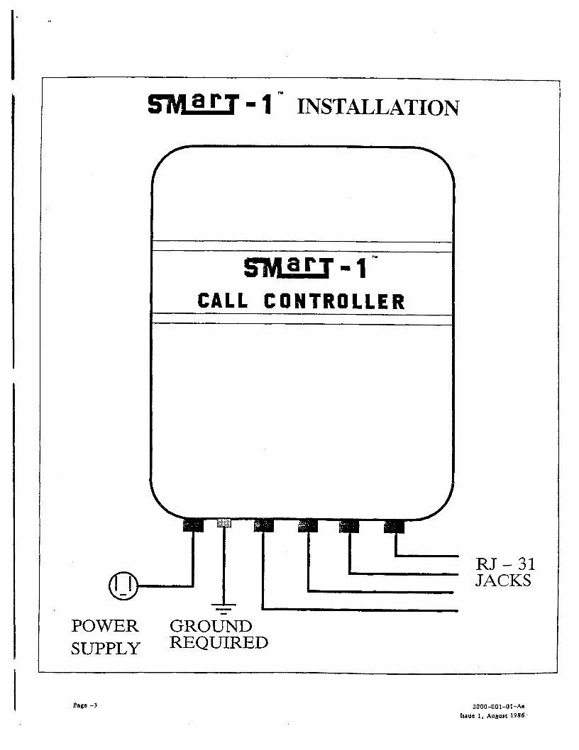
- i n INSTALLATION
CALL CONTROLLE
RJ-31 JACKS
POWER GROlhD SUPPLY REQUIRED
Page -3 ZOOO-OOl-Ol-Ae
Issue 1. Augurt 1986


- 1 n RJ - 31 INSTALLATION
CENTRAL
Page -4 ZDOO-OOl-Ol-AC Issue 1, August 1986


- 1 Ty WIRING TEST
f
swu-1 CALL CORTROLLlR
t
0-J GROUND
Page -5
TO SMart 1
ZOOO-OOl-Ol-Ae Issue 1. August 1986

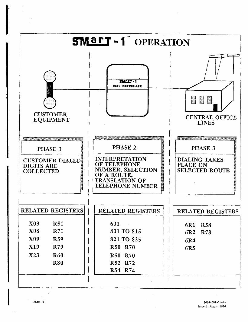
- 1 T” OPERATION
CUSTOMER EQUIPMENT
DIGITS ARE COLLECTED
{ELATED REGISTERS
x03 R51 X08 R71 x09 R59 x19 R79
X23 R60 R80
PHASE 2
INTERPRETiiTION OF TELEPHONE NUMBER, SELECTION OF A ROUTE, TRANSLATION OF TELEPHONE N-UMBER
I RELATED REGISTERS 1
601 I
801 TO 815 I
821 TO 835 I R50 R70 I R50 R70 R52 R72 I
R54 R74 I
’ I
1 DIALING TAKES PLACE ON
1 SELECTED ROUTE
II
1 RELATED REGISTERS
6Rl R58 6R2 R78 6R4 6R5
Page -6 ZOOO-OOI-Ol-Ae Issue 1, August 1986

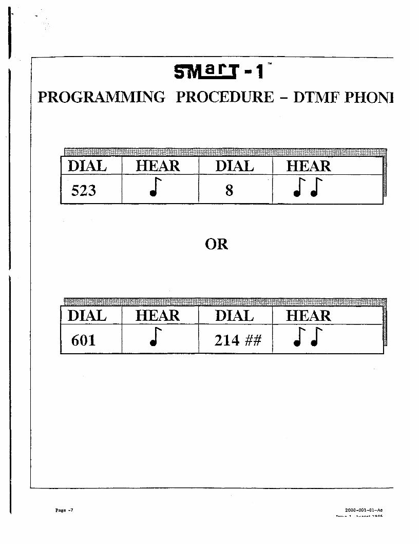
PROGRAMMING PROCEDURE - DTMF PHONE
DIAL 1 HEAR DIAL t HEAR
523 s 8 ss OR
DIAL 1 HEAR DIAL t HEAR
601 s 214 ##
Page -7 2000-OOI-Ol-Ae

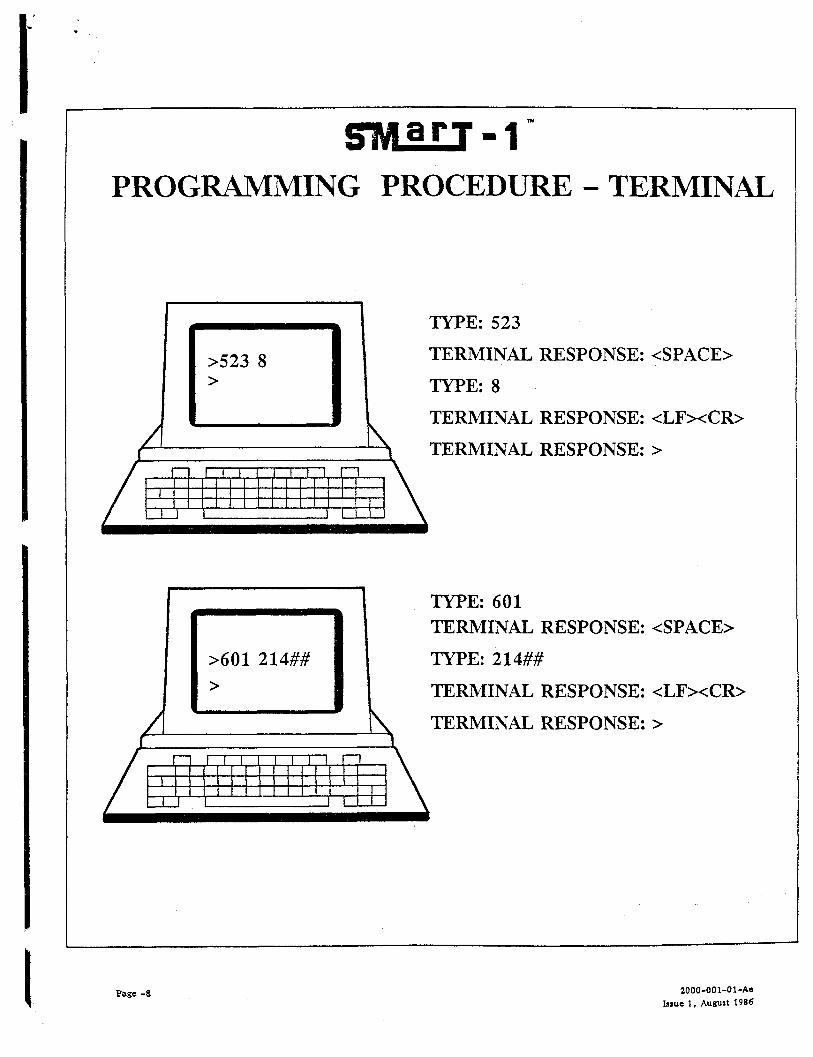
. I
PROGRAMMING PROCEDURE - TERMINAL
c
>523 8 >
TYPE: 523
TERMINAL
TYPE: 8
TERMINAL RESPONSE: <LFxCR>
TERMINAL RESPONSE: >
RESPONSE: <SPACE>
/ \
TYPE: 601 TERMINAL RESPONSE: <SPACE>
TYPE: 214##
TERMINAL RESPONSE: <LFxCR>
TERMINAL RESPONSE: >
Page -8 2000-001-Ol-Ae fssue I. August 1986

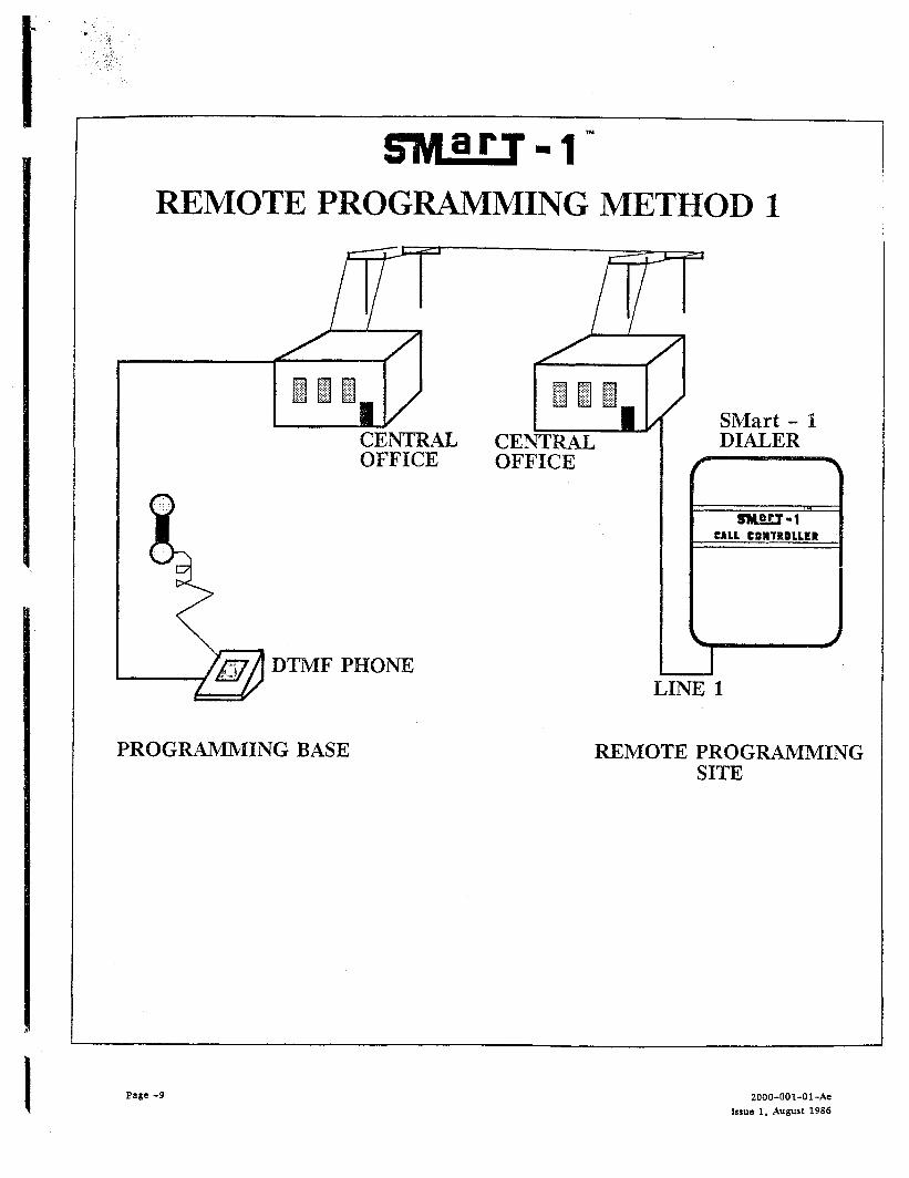
REMOTE PROGRAMMING METHOD 1
CENTRAL OFFICE
DTMF PHONE
@E OF
LINE 1
PROGRAMMING BASE REMOTE PROGRAMMING SITE
Page -9 ZOOO-OOI-Ol-Ae ksue 1. Auysr 1986

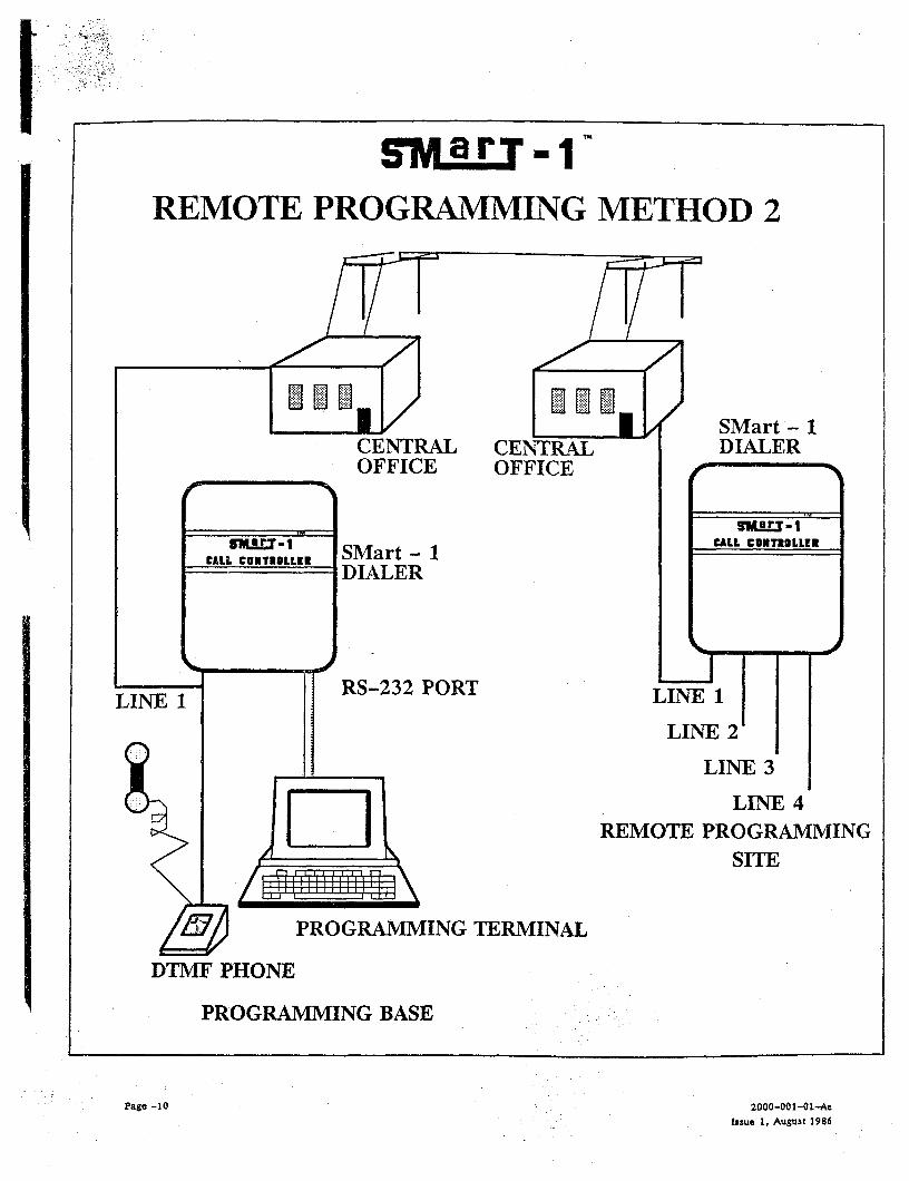
gyarpl- REMOTE PROGRAA’IMING METHOD 2
SMart - 1 DIALER
PROGRAMMING TERMINAL
DTMF PHONE
PROGRAMMING BASE
LINE 4 REMOTE PROGRAMMIN
SITE ‘G
Page -10 2000-OOl-OL-Ae issue 1. August 1986

r:.
.
,’