Exercise modelbuilder for beginners - MIT Libraries, MIT Library

1
MIT Research Innovative Use of Metamaterials in
Confining, Controlling, and Radiating Intense Microwave Pulses
Michael Shapiro and Richard Temkin MIT Dept. of Physics
MIT Plasma Science and Fusion Center
MURI Kickoff at Univ. New Mexico August 21, 2012

2
Outline
• MIT HPM Research Capabilities
• MTM HPM Amplifier Design
• S-Band MTM Amplifier Experiment – First Design
• Summary

3
MIT Accelerator and HPM Lab
MIT Accelerator Parameters
Klystron Power 25 MW
RF Frequency 17.14 GHz
Linac Energy 25 MeV
Linac Length 0.5m, 94 cells
Test Stand Power 4 MW

4
700 kV Modulator
MIT Modulator Parameters
Modulator Voltage 700 kV
Modulator Pulsed Power
500 MW
Beam Current 780 A
Modulator Pulse Length
1.0 ms Flat-top
Klystron Power 25 MW
Modulator V, I Waveforms
Features of Long Pulses • High Energy • Equilibrium • For Q~5000 and ω ~ 3 GHz,
Q/ω ~300 ns

5
Previous MIT HPM Experiments
• Injection locked 3.3 GHz Magnetron, 30 MW, 400 ns
• Cyclotron Autoresonance Maser (CARM) oscillator, 1.9 MW, 28 GHz in 1 ms pulses; 450 kV, 80 A, 5.2% efficiency
• Free Electron Laser Oscillator, 1 MW, 27 GHz in 1 ms pulses at 10% efficiency; 320 kV and 30A
• Haimson Research Corp. 17.1 GHz Klystron; 525 kV, 100A
– First version: 25 MW with 50 dB of gain
– Second version: 25 MW with 71 dB of gain

6
SLAC 5045 Electron Gun • SLAC 5045 Klystron Gun built for MIT
Magnetic Field Profile ~ 1.4 kG SLAC 5045
Klystron
• 350 kV • 414 A • Perveance 2 µP • E Beam Power 145 MW • Microwave P = 65 MW

7
Haimson Research Choppertron
• Test of Choppertron
Choppertron Schematic Choppertron Gun 500 kV, 80A Electron Beam diameter 4 mm

8
MIT RF Breakdown Research at 11.4 GHz • RF breakdown could be a major issue for MTM structures
• Standing wave Photonic Bandgap structures with half field in each of 2 coupling cells and full field in test cell
– Designed at MIT, built and tested at SLAC
Input Matching Cell
End Matching Cell
PBG Test Cell
TM01 In
WR-90 In
TM01 Out

9
Metallic PBG Structures • Achieved high gradient and
low breakdown rate at 11.4 GHz
– 3.6 * 10^-3 /pulse/m @128 MV/m
– Surface field is about 250 MV/m
• Breakdown testing will begin at MIT at 17.1 GHz in 2012
Gra
dien
t
Acc
umul
ated
Bre
akdo
wns

10
Gyrotron and TWT Research Lab • Two experiments operate from a single power supply
– 100 kV, 120 A, 2 ms flat-top
1.5 MW 110 GHz Gyrotron 96 kV, 42 A
0 2 4 6-100
-80
-60
-40
-20
0
Time (us)
rf d
iode
vol
tage
(mV)
Output Power

11
94 GHz TWT Experimental Design
Slow wave structure Electron Gun Beam tunnel
Magnet (Solenoid)
RF in RF out
Operation Parameters
Frequency 94 GHz
V0 31.1 kV
Current 330 mA
Kinetic Spread
0.1%
Beam radius 0.3 mm
Cavities 86
Length 6.88 cm
K at 94GHz 2.8 Ohms
Cold Circuit Bandwidth
4 GHz
Magnetic Field
2.5 kG
12
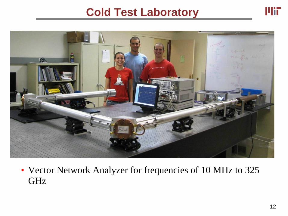
Cold Test Laboratory
• Vector Network Analyzer for frequencies of 10 MHz to 325 GHz

13
Outline
• MIT HPM Research Capabilities
• MTM HPM Amplifier Design
• S-Band MTM Amplifier Experiment – First Design
• Summary

14
Theory Overview
• MTM amplifier will be based on an electron beam from a Pierce gun with solenoidal magnet focusing and transport through a MTM structure
• Design procedure will be similar to conventional TWT designs
– First: design an electron beam system and magnet
– Second: design the amplifier circuit, estimate linear gain
– Third: calculate the saturated gain using CST particle studio
• We have a preliminary (first) MTM structure design
– We would like to try other designs suggested by other team members

15
94 GHz Electron Gun Design
• Pierce electron gun designed with Michelle (SAIC) for operation at: 31 kV, 330 mA, 0.25 mm beam radius
• 4 A/cm2 at cathode; 1.63 mm/0.25mm compression ratio
Michelle Simulation

16
CST and Latte Simulations
• CST Particle Studio (3D PIC code) simulations with 86 cavity (6.88 cm long) structure at 94GHz
• Results show 32 dB gain with 300 W peak output power and 200 MHz bandwidth
• 3D CST results agree with 1D LMSuite Latte Simulations with 4 dB/cm loss and 3 Ω coupling impedance

17
Beam-driven power source: • Waveguide with perforated walls is used • TM mode interacts with electron beam • Very low group velocity – high coupling to electron beam C-SRR
εeff<0
TM-mode WG μeff<0
metal
Beam-powered Negative Index Complementary Metamaterial
Collaboration with UT-Austin (G. Shvets group)

18
Negative Index Complementary Metamaterial
12.8 mm
8 mm
Design at f=5.5 GHz
6.6 mm
4.6 mm 0.8 mm width
0.3 mm
Single cell HFSS simulation
C-SRR dimensions
C-MTM model: • infinite in transverse direction • wave propagates along plates • multiple beams (or continuous)

19
Extracted effective parameters
eeff <0 heading towards resonance
Flat meff <0 similar to smooth TM mode WG
Magneto-electric coupling κeff due to C-SRR’s asymmetry
Phase advance (rad.)
COMSOL simulation

20
Beam-NIM instability
M. A. Shapiro et al., “Active Negative-index metamaterial powered by an electron beam” to be published in PRB 2012
22
2
222
22
)1(
)()(
beffeff
bxeffeffeffx
c
vkc
k
wemw
wkmew
-
=-÷÷ø
öççè
æ--
Dispersion equation is analogous to TWT equation: three waves – growing, decaying, and neutral Beam plasma frequency ωb
3/12
2
2
max )1(21
23
÷÷ø
öççè
æ-= beffeff
b
cv wwemg
Maximum gain:
gain

21
Outline
• MIT HPM Research Capabilities
• MTM HPM Amplifier Design
• S-Band MTM Amplifier Experiment – First Design
• Summary

22
S-Band MTM Amplifier Experiment
• S-Band (2 -4 GHz) amplifier
– Wavelength of 10 cm
– Structure size and breakdown field more manageable
• Input power ~ 100 kW; about 10 to 100 MW output, so we will need 20 to 30 dB of saturated gain
• Plan A is to use SLAC 5045 electron gun: 350 kV, 414A
– Beam size about 24 mm in diameter, equal to about l/4
– Magnetic field requirement is 1.4 kG over 0.75 m length
• Plan B is to use Haimson Research Choppertron gun: 500 kV, 80 A, 4 mm beam diameter
– Already mounted to MIT modulator tank

23
Schematic of MTM Amplifier
• Schematic is based on previous implementation of SLAC 5045 electron gun on MIT modulator tank
• SLAC gun shown on right for comparison

24
Acknowledgements
• Research supported by: – Air Force Office of Scientific Research
• MIT Research Group:
Faculty and Staff
William Guss Ivan Mastovsky Michael Shapiro Richard Temkin Paul Thomas Paul Woskov Postdocs: Min Hu Sudheer Jawla
Grad Students
Sergey Arsenyev Jason Hummelt Elizabeth Kowalski Xueying Lu Brian Munroe Emilio Nanni Samuel Schaub Sasha Soane David Tax Jiexi Zhang