MISSOURI DEPARTMENT OF TRANSPORTATION … Buyers Web Page/documents...MISSOURI DEPARTMENT OF...
26
1 MM-C MISSOURI DEPARTMENT OF TRANSPORTATION ADULT PASSENGER LIGHT DUTY CUTAWAY TYPE VEHICLE SPECIFICATIONS - WIDE BODY The intent of these general specifications is to describe a commercial non-school bus type vehicle that will be manufactured, structured and assembled by using best quality materials, components and workmanship in accordance with sound engineering principles and manufacturing practices to provide safe and reliable highway and city transportation for ambulatory and non-ambulatory adult passengers. Chassis types - Cutaway Vans, Commercial Cutaways or R.V. Cutaways, 2017 or 2018 model year, General Motors 14,000 GVWR, Ford Super Duty 14,000 GVWR or approved equal. All vehicles must meet GVWR requirements for anticipated passenger load. If for any reason a 2017 model cannot be supplied a 2018 model must be furnished at quoted bid price. This will only be exercised in the event a successful bidder received a purchase order in time to order a chassis and failed to do so. Floor Plan II may utilize a 158” 14,000 GVWR chassis. These vehicles shall be tested at the FTA’s Altoona Bus Testing and Research Center and the testing report submitted to the Missouri Department of Transportation with the bid. These vehicles will also meet all current Federal Motor Carrier regulations at time of manufacture. The Fixing America’s Surface Transportation (FAST ACT) increases domestic percentage content requirements for Buy America through incremental increases. By FFY 2020, the Buy America requirement for rolling stock will total 70 percent. The FAST Act also makes important changes to the waiver denial process, requiring FTA to certify the availability and quality of the domestic sources for the product in the denied waiver. Buy America minimum requirements in each federal fiscal year are identified as follows: FFY17 rolling stock must meet the minimum 60% domestic content; final assembly processes and final assembly point in USA. FFY18 and 19 rolling stock must meet the minimum 65% domestic content; final assembly processes and final assembly point in USA. FFY2020 rolling stock must meet the minimum 70% domestic content; final assembly processes and final assembly point in USA. Evaluation of the minimum domestic content requirements will be completed prior to award of the next fiscal year rolling stock award. MoDOT reserves the right to conduct in-plant inspections.
Transcript of MISSOURI DEPARTMENT OF TRANSPORTATION … Buyers Web Page/documents...MISSOURI DEPARTMENT OF...

1
MM-C
MISSOURI DEPARTMENT OF TRANSPORTATION ADULT PASSENGER LIGHT DUTY CUTAWAY
TYPE VEHICLE SPECIFICATIONS - WIDE BODY The intent of these general specifications is to describe a commercial non-school bus type vehicle that will be manufactured, structured and assembled by using best quality materials, components and workmanship in accordance with sound engineering principles and manufacturing practices to provide safe and reliable highway and city transportation for ambulatory and non-ambulatory adult passengers. Chassis types - Cutaway Vans, Commercial Cutaways or R.V. Cutaways, 2017 or 2018 model year, General Motors 14,000 GVWR, Ford Super Duty 14,000 GVWR or approved equal. All vehicles must meet GVWR requirements for anticipated passenger load. If for any reason a 2017 model cannot be supplied a 2018 model must be furnished at quoted bid price. This will only be exercised in the event a successful bidder received a purchase order in time to order a chassis and failed to do so. Floor Plan II may utilize a 158” 14,000 GVWR chassis. These vehicles shall be tested at the FTA’s Altoona Bus Testing and Research Center and the testing report submitted to the Missouri Department of Transportation with the bid. These vehicles will also meet all current Federal Motor Carrier regulations at time of manufacture. The Fixing America’s Surface Transportation (FAST ACT) increases domestic percentage content requirements for Buy America through incremental increases. By FFY 2020, the Buy America requirement for rolling stock will total 70 percent. The FAST Act also makes important changes to the waiver denial process, requiring FTA to certify the availability and quality of the domestic sources for the product in the denied waiver. Buy America minimum requirements in each federal fiscal year are identified as follows:
FFY17 rolling stock must meet the minimum 60% domestic content;
final assembly processes and final assembly point in USA. FFY18 and 19 rolling stock must meet the minimum 65% domestic
content; final assembly processes and final assembly point in USA. FFY2020 rolling stock must meet the minimum 70% domestic content;
final assembly processes and final assembly point in USA.
Evaluation of the minimum domestic content requirements will be completed prior to award of the next fiscal year rolling stock award. MoDOT reserves the right to conduct in-plant inspections.

2
Body Exterior: The materials used and the assembly method of the roof, side panels, and floor will be the manufacturer's standard construction, uniformly connected, lapped and sealed providing a weather and dust proof body. Drip rails shall be installed above all doors to prevent water leakage into bus. Drip rails will be 3/4" or more in width. Each vehicle will be thoroughly water tested before delivery. A 23’ body is acceptable provided it meets all interior dimensions. Body width not to exceed 98”, excluding wheel flares and mirrors.
Wheel Flairs: Wheel flairs shall be of metal construction, thick reinforced fiberglass or thermo-plastic olefin (TPO) to resist breakage from ice and snow thrown off tires and from the wheel well. Vehicle shall be warranted against any paint rust-through for minimum three years from the date of delivery to the end user. Vehicle will have a complete application of undercoating that will not interfere with OEM requirements. Exterior Color: Vehicle base color will be white. Advertisements: A dealer identification decal no larger than 20 inches square inches in area may be displayed on the back of the vehicle and/or under the hood in the engine compartment of the vehicle.
Body Interior: The inner construction must provide equal protection to passengers regardless of where they are seated. The inner frame, at the floor, front and rear ends shall be heavy steel construction that will provide solid support for inner crash shield and exterior panels. The frame shall be securely anchored to adequately spaced steel floor cross members. The entire structure must provide maximum resistance to impact and collision and meet or exceed the rollover protection requirement of all federal regulations. (FMVSS 220).
Interior Color: The interior trim, upholstery, seat belts, visors, and etc., will be color keyed to exterior color. Headliner: Shall be full length for driver and passenger area. This headliner shall have longitudinal and cross member supports where needed to prevent flexing and vibrations.
3
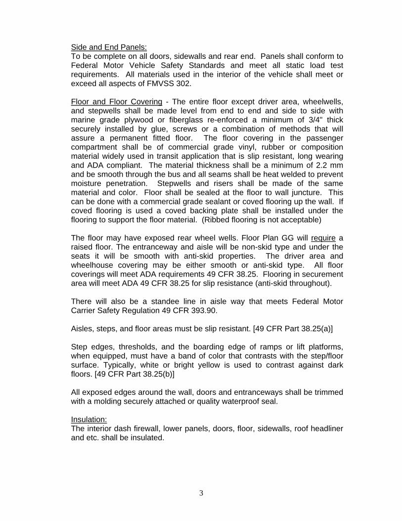
Side and End Panels: To be complete on all doors, sidewalls and rear end. Panels shall conform to Federal Motor Vehicle Safety Standards and meet all static load test requirements. All materials used in the interior of the vehicle shall meet or exceed all aspects of FMVSS 302.
Floor and Floor Covering - The entire floor except driver area, wheelwells, and stepwells shall be made level from end to end and side to side with marine grade plywood or fiberglass re-enforced a minimum of 3/4" thick securely installed by glue, screws or a combination of methods that will assure a permanent fitted floor. The floor covering in the passenger compartment shall be of commercial grade vinyl, rubber or composition material widely used in transit application that is slip resistant, long wearing and ADA compliant. The material thickness shall be a minimum of 2.2 mm and be smooth through the bus and all seams shall be heat welded to prevent moisture penetration. Stepwells and risers shall be made of the same material and color. Floor shall be sealed at the floor to wall juncture. This can be done with a commercial grade sealant or coved flooring up the wall. If coved flooring is used a coved backing plate shall be installed under the flooring to support the floor material. (Ribbed flooring is not acceptable)
The floor may have exposed rear wheel wells. Floor Plan GG will require a raised floor. The entranceway and aisle will be non-skid type and under the seats it will be smooth with anti-skid properties. The driver area and wheelhouse covering may be either smooth or anti-skid type. All floor coverings will meet ADA requirements 49 CFR 38.25. Flooring in securement area will meet ADA 49 CFR 38.25 for slip resistance (anti-skid throughout).
There will also be a standee line in aisle way that meets Federal Motor Carrier Safety Regulation 49 CFR 393.90.
Aisles, steps, and floor areas must be slip resistant. [49 CFR Part 38.25(a)]
Step edges, thresholds, and the boarding edge of ramps or lift platforms, when equipped, must have a band of color that contrasts with the step/floor surface. Typically, white or bright yellow is used to contrast against dark floors. [49 CFR Part 38.25(b)]
All exposed edges around the wall, doors and entranceways shall be trimmed with a molding securely attached or quality waterproof seal.
Insulation: The interior dash firewall, lower panels, doors, floor, sidewalls, roof headliner
and etc. shall be insulated.

4
Grabrails, Stanchions: A floor to ceiling stanchion shall be installed near the aisle and immediately
left of the entrance door. This stanchion shall be connected to the vehicle right side by a guardrail approximately 30" above the floor.
Interior handrails and stanchions should not interfere with the path of travel of a common wheelchair from the accessible entrance to the securement areas. [49 CFR Part 38.29(a)]
For vehicles longer than 22 feet, an overhead handrail or handrails shall be provided which are continuous from front to back except for a gap at the rear doorway. [49 CFR Part 38.29(c)]
A floor to ceiling stanchion shall be installed in close proximity to the rear,
right side of the driver's seat. This stanchion shall be connected to the vehicle's left hand side wall by a guardrail approximately 30" above the floor. The stanchion and guardrail shall not impair the driver's seat adjustment. Two stanchions with a modesty panel behind the driver’s seat are also acceptable.
A solid material modesty panel on all floor plans shall be provided with the entry door stanchion and guardrail. A solid modesty panel on Floor Plans CC, and GG shall be provided immediately aft of the wheelchair lift entry area and immediately in front of the right hand / street-side seat immediately behind the lift. Spacing of these guardrails and panels must provide adequate passenger knee room. There will also be two overhead grabrails mounted securely above the passenger aisleway. These grabrails will meet ADA requirement 49 CFR 38.29. One overhead rail is acceptable if storage compartment is an issue, such as the optional storage shelving.
Stepwell Grabrails: There will be two parallel mounted grabrails located along the entire length of the stepwell. The left side grabrail will mounted to the entrance door frame, or floor, on the lower end and on the floor to ceiling stanchion on the upper end. The right side grabrail will be mounted to the door frame, or floor, on the lower end and then either securely mounted to a floor to ceiling stanchion or steel mounted to the upper windshield frame. These grabrails shall be approx. 18” in length. All handrails, grabrails and stanchions will meet ADA requirement 49 CFR 38.29. All stanchions guardrails, grabhandles, and grabrails will be mounted to the floor or ceiling with at least four screws, or at least two screws that are attached to steel mounted backing plates.

5
All handrails and stanchions will meet ADA requirement 49 CFR 38.29.
Handrails and stanchions shall be provided in the entrance area and through the fare collection area to assist persons with disabilities as they enter and pay a fare. Some portion of this handrail/stanchion system must be able to be grasped from outside the vehicle to assist persons as they start to board. Handrails shall have a cross-sectional diameter of 1 1/4 to 1 1/2 inches, shall provide a minimum of 1 1/2 inches of "knuckle clearance," and shall have eased edges with corner radii of not less than 1/8 inch.
On vehicles 22 feet in length or longer which have fare collection systems, a horizontal assist shall be provided across the front of the vehicle to allow a person to lean against the assist while paying a fare. [49 CFR Part 38.29(b)] Handrails and stanchions shall also be provided to assist with on-board circulation, sitting and standing, and exiting the vehicle. [49 CFR Part 38.29(b)] Location and provisions for fareboxes are to be located as far forward as possible and must not obstruct traffic in the vestibule area, particularly wheelchairs and mobility aids. [49 CFR Part 38.33] For vehicles longer than 22 feet that have front door lifts or ramps, vertical stanchions immediately behind the driver shall either terminate at the lower edge of the aisle-facing seats or be "dog-legged" so that the floor attachment does not impede or interfere with wheelchair footrests. [49 CFR Part 38.29(e)] The vertical stanchions behind the driver need only terminate with a “dog leg”, if such bending of the stanchion is necessary to eliminate impedance of access to the securement area or to eliminate interference with wheelchair footrests of wheelchairs in the securement area. If the driver's seat must be passed by a wheelchair user, the pedestal shall not extend into the aisle or vestibule beyond the wheel housing, to the maximum extent practicable. [49 CFR Part 38.29(e)]
Seating, Seat Belts, and Seating Arrangements: See Exhibits CC, GG, HH, and II. The arrangements shall provide seating as listed and as shown on the appropriate exhibit. If there is a conflict between the written specification and the floor plan diagram, the written narrative controls. Narrative controls the design. At least one set of forward-facing seats must be designated as priority seats for persons with disabilities. Signs identifying these as priority seats must be provided. Characters on these signs shall have a width to height ratio between 3:5 and 1:1 and a stroke width to height ratio between 1:5 and 1:10. Minimum character height (using a capital X) shall be 5/8 inch. Wide spacing
6
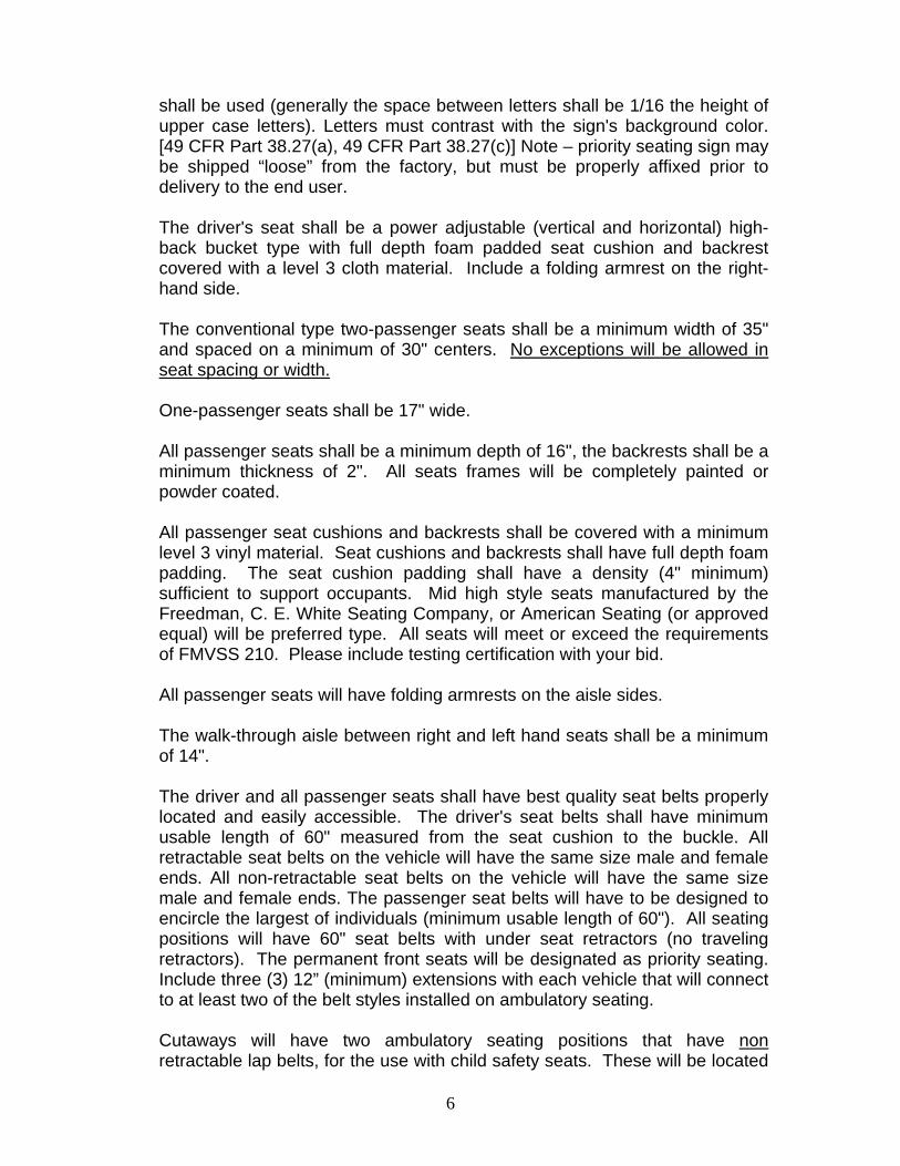
shall be used (generally the space between letters shall be 1/16 the height of upper case letters). Letters must contrast with the sign's background color. [49 CFR Part 38.27(a), 49 CFR Part 38.27(c)] Note – priority seating sign may be shipped “loose” from the factory, but must be properly affixed prior to delivery to the end user.
The driver's seat shall be a power adjustable (vertical and horizontal) high-back bucket type with full depth foam padded seat cushion and backrest covered with a level 3 cloth material. Include a folding armrest on the right-hand side. The conventional type two-passenger seats shall be a minimum width of 35" and spaced on a minimum of 30" centers. No exceptions will be allowed in seat spacing or width. One-passenger seats shall be 17" wide. All passenger seats shall be a minimum depth of 16", the backrests shall be a minimum thickness of 2". All seats frames will be completely painted or powder coated. All passenger seat cushions and backrests shall be covered with a minimum level 3 vinyl material. Seat cushions and backrests shall have full depth foam padding. The seat cushion padding shall have a density (4" minimum) sufficient to support occupants. Mid high style seats manufactured by the Freedman, C. E. White Seating Company, or American Seating (or approved equal) will be preferred type. All seats will meet or exceed the requirements of FMVSS 210. Please include testing certification with your bid.
All passenger seats will have folding armrests on the aisle sides. The walk-through aisle between right and left hand seats shall be a minimum of 14". The driver and all passenger seats shall have best quality seat belts properly located and easily accessible. The driver's seat belts shall have minimum usable length of 60" measured from the seat cushion to the buckle. All retractable seat belts on the vehicle will have the same size male and female ends. All non-retractable seat belts on the vehicle will have the same size male and female ends. The passenger seat belts will have to be designed to encircle the largest of individuals (minimum usable length of 60"). All seating positions will have 60" seat belts with under seat retractors (no traveling retractors). The permanent front seats will be designated as priority seating. Include three (3) 12” (minimum) extensions with each vehicle that will connect to at least two of the belt styles installed on ambulatory seating.
Cutaways will have two ambulatory seating positions that have non retractable lap belts, for the use with child safety seats. These will be located
7
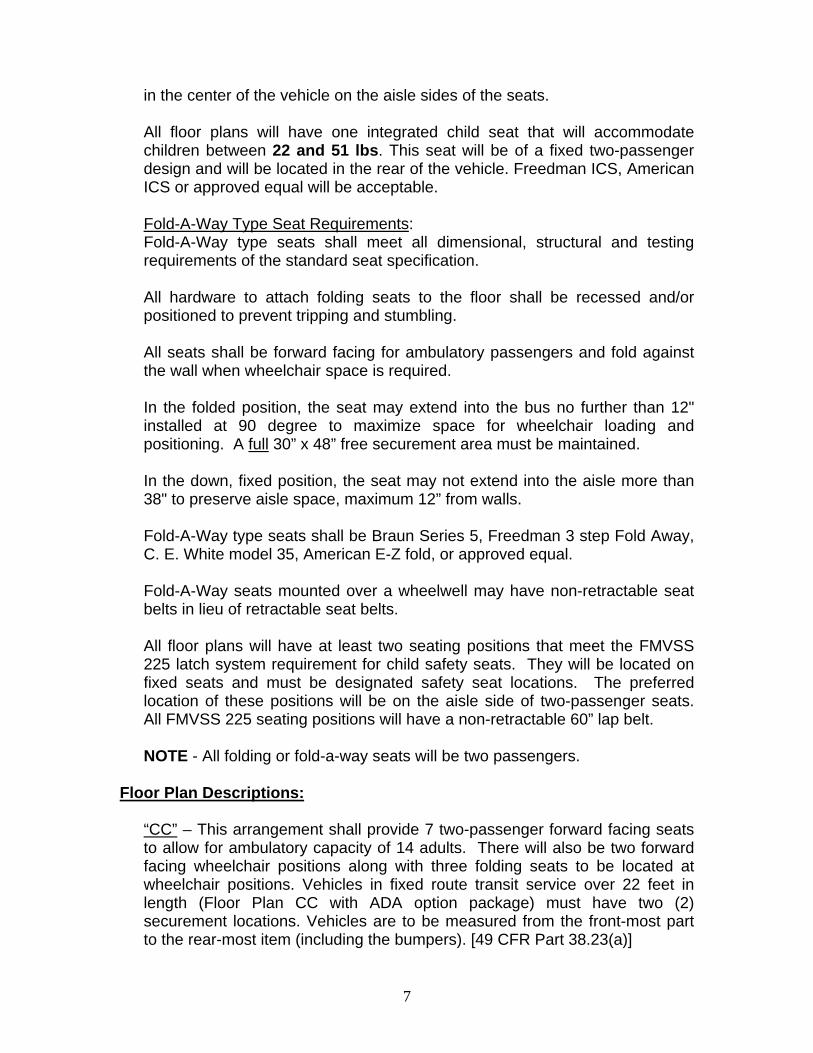
in the center of the vehicle on the aisle sides of the seats. All floor plans will have one integrated child seat that will accommodate children between 22 and 51 lbs. This seat will be of a fixed two-passenger design and will be located in the rear of the vehicle. Freedman ICS, American ICS or approved equal will be acceptable.
Fold-A-Way Type Seat Requirements: Fold-A-Way type seats shall meet all dimensional, structural and testing requirements of the standard seat specification. All hardware to attach folding seats to the floor shall be recessed and/or positioned to prevent tripping and stumbling. All seats shall be forward facing for ambulatory passengers and fold against the wall when wheelchair space is required. In the folded position, the seat may extend into the bus no further than 12" installed at 90 degree to maximize space for wheelchair loading and positioning. A full 30” x 48” free securement area must be maintained. In the down, fixed position, the seat may not extend into the aisle more than 38" to preserve aisle space, maximum 12” from walls. Fold-A-Way type seats shall be Braun Series 5, Freedman 3 step Fold Away, C. E. White model 35, American E-Z fold, or approved equal. Fold-A-Way seats mounted over a wheelwell may have non-retractable seat belts in lieu of retractable seat belts. All floor plans will have at least two seating positions that meet the FMVSS 225 latch system requirement for child safety seats. They will be located on fixed seats and must be designated safety seat locations. The preferred location of these positions will be on the aisle side of two-passenger seats. All FMVSS 225 seating positions will have a non-retractable 60” lap belt. NOTE - All folding or fold-a-way seats will be two passengers.
Floor Plan Descriptions:
“CC” – This arrangement shall provide 7 two-passenger forward facing seats to allow for ambulatory capacity of 14 adults. There will also be two forward facing wheelchair positions along with three folding seats to be located at wheelchair positions. Vehicles in fixed route transit service over 22 feet in length (Floor Plan CC with ADA option package) must have two (2) securement locations. Vehicles are to be measured from the front-most part to the rear-most item (including the bumpers). [49 CFR Part 38.23(a)]

8
"GG" - this plan requires a raised floor. Four (4) wheelchair positions will be located behind the driver with a fifth (5th) position located at the rear of the bus curbside. There will be two (2) two-passenger fold-a-way seats located on the curbside behind the lift. Total capacity five (5) wheelchairs with seating for four (4) ambulatory. Delete the Integrated Child seat requirement, the CRS requirement remains.
"HH" - this floor plan will provide two permanent wheelchair positions. The lift will be located at the right rear of the bus and all permanent ambulatory seating will be located towards the front (16 passenger ambulatory capacity).
"II" - this floor plan will be similar to "HH" except it will seat 12 ambulatory instead of 16. Note – the rearmost 2-place seats on the driver’s side and the curbside shall be fold-away seats.
Windshield, Door Glass and Window Glass: Safety plate windshield and window glass all around. The windshield shall be fixed glass. Passenger side windows shall be provided throughout the passenger area. These windows will be a horizontal opening type that easily open and close. These windows shall meet all the latest federal regulations for retention and release. Kick-out type windows will be hinged at the top. All windows that are considered as emergency exits will be clearly marked. A full-length drip molding of at least 3/4" will be installed over each passenger window opening. The driver position, on buses with right hand front entrance door only, shall have a window that can be opened for ventilation at the left side. The dual right hand passenger entrance doors shall have full-length windows that will allow the driver to judge curb location. The emergency rear door shall have an upper and lower fixed glass. There will be glass on each side of the emergency door, approximately 24" x 24" or 7" x 30".
The windshield, driver position side window, and rear emergency door glass will be tinted. The passenger entrance door glass will be tinted in the upper part and may be clear in the lower part. All passenger area side window glass will be tinted. An approximate tinting of 30% light transfer is acceptable. All sliding side windows will have inside latches for security.

9
All windows, doors, and windshield will be installed to keep water and dust leakage to an absolute minimum. Proper sealing during installation is essential. Doors: One door RH or two doors LH and RH acceptable. Entrance LH - This door shall be the chassis manufacturer's standard front side door with tinted drop glass armrest and lock. This door may be modified if necessary. Entrance RH - Main service door may be either forward folding, in-out or out-out opening type. This door shall provide no stoop entry headroom with a minimum of 72" entrance height from the top of the first entrance step to the door headliners. The minimum width shall be a 24". The top of the door entrance shall be fully enclosed and protected from weather and other elements. It shall have protective padding to prevent head injury when entering or exiting. All vehicles will have an electrically operated door. The electric door will also be forward folding, in out or out-out opening type. This door will be operated by a switch from the driver’s areas. There will also be a key activated switch on the right exterior of the bus so the door can be opened from the outside. The door and control arms will be located above the door area, not beneath the stepwell. Either door shall have a below floor level entrance stepwell, with a minimum of two steps. These steps shall be stationery, corrosion resistant steel adequately braced and be an integral part of the basic structure. The height from ground to top of first step of empty vehicle be a maximum of 13-1/2" and a minimum of 10". Additional step heights will be a maximum of 11", the head depth for all steps shall be a minimum of 8". All of the steps shall be level and the risers shall be vertical or slightly angled. Each step will be covered with molded rubber or vinyl. The step covering will be non-skid type tread with white or yellow nosing. The riser shall be covered, painted, or coated with scuff resistant material. These steps will be fully recessed, enclosed and protected from weather and other elements. Door sweeps or flaps will be installed on bottom edges of doors. The bottom step of the stepwell may protrude below the door, but the door must incorporate a door sweep or flap on the bottom edge of the door. A stepwell light shall be provided and automatically operated by door control.
The entire door shall be weather stripped to provide a water and airtight seal. The door edge seals will be the over-lapping type to provide maximum sealing ability. The door opening shall be structurally reinforced to have the same structural integrity as the body.

10
(If Required) RH side lift door or doors –(with window) This entranceway may have either single or dual swing-out type door or doors (double doors preferred). Positive exterior latching mechanism will be provided to keep door(s) held open during lift operations. The door(s) height extended from the floor to the top and side-to-side of the entranceway shall provide adequate clearance for the ramp and wheelchair entry. (68" minimum) This entranceway will be located forward in the right hand side of the body, across from the wheelchair securement area or in the rear of the bus, along the curbside. Please note lift position in each floor plan. Lift door will meet all requirements of ADA 49 CFR 38.25.
The height of doors at accessible entrances and the interior height along the path of travel between accessible entrances and securement areas shall be as follows:
For vehicles 22 feet or longer, the clearance from the raised lift platform or the ramp surface to the top of the door must be at least 68 inches.
For vehicles less than 22 feet, the overhead clearance must be at least 56 inches. [49 CFR Part 38.25(c)]
The entranceway shall be protected from weather and other elements and be padded to prevent head and other injuries to passengers when exiting or entering. Rear Emergency Door: This door shall be outward opening type, clearly marked as an exit. The dimensions of this door will be approximately 32" wide and 50" high. This door shall have an open door warning buzzer and will be sealed to minimize dust and moisture entry. A red interior emergency light shall be installed above the rear emergency door that illuminates when ignition is in the on position. This door opening shall have protective padding to prevent head injury when exiting. The rear emergency door must have an inside latch and release mechanism and outside handle. This door shall have factory installed position hold and check arm. Vehicles will have a warning device (buzzer) that indicates a locked rear emergency door. Emergency door will have an inside lock. Warning device will meet all FMVSS requirements. All doors will meet ADA requirement 49 CFR 38.25.
11
Door Lock System: The bus shall have a security door lock system for all doors. Wheelchair Lift (if required): The lift shall be an electrohydraulic type providing power-up, power or gravity down and power automatic fold. The power source shall be the vehicle 12-volt electrical system. The lift will be mounted within the body with access through the right hand side load door or doors. Modifications for the lift installation must not affect the structural integrity of the basic vehicle. The lift shall have a minimum rated working load capacity of 800 lbs. with an option to include a lift with a capacity of 1,000 lbs. The design load of a lift must be at least 800 pounds, per MoDOT specifications. Working parts must have a safety factor of at least six Non-working parts shall have a safety factor of at least three [49 CFR Part 38.23(b)(1)] The lift will have no dirty or greasy surfaces that will contact the wheelchair occupant during normal operation. The platform surface must be slip resistant with no protrusions over 1/4 inch. [49 CFR Part 38.23(b)(6)] The lift platform shall be constructed of expanded metal with a minimum usable width of 33" and a minimum depth of 51". The platform must be at least 28 1/2-inches wide measured at the platform surface and at least 30 inches wide measured from 2 inches above the platform surface to 30 inches above the surface. It must also be at least 48 inches long measured from 2 inches above the surface to 30 inches above the surface. [49 CFR Part 38.23(b)(6)] Gaps between the platform surface and any barrier can be no more than 5/8 inch. Semi-automatic lifts can have a handhold in the platform that measures no more than 1 1/2 inches by 4 1/2 inches. [49 CFR Part 38.23(b)(7)] When in the fully raised position, the platform surface must be vertically within 5/8 inch of the finished floor and horizontally within 1/2 inch of the finished floor. [49 CFR Part 38.23(b)(7)] The platform must not deflect more than 3 degrees in any direction when a 600-pound load is placed on the center of the platform. [49 CFR Part 38.23(b)(9)]
The platform must raise or lower in no more than 6 inches per second. The platform must be stowed or deployed in no more than 12 inches per second. Horizontal acceleration can be no more than 0.3 g. [49 CFR Part 38.23(b)(10)]

12
Components of a lift must be designed to allow boarding in either direction. [49 CFR Part 38.23(b)(11)]
The lift shall have the following: A manual override to lower, to raise and an emergency platform release for use
in the event of power failure. The pump handle will be able to function without interference from interior obstructions.
Lifts must be equipped with an emergency backup system. The emergency backup system shall be capable of being operated both up and down without the platforms "stowing" while occupied. [49 CFR Part 38.23(b)(3)] Must be designed so that in the event of a power failure, the platform cannot fall faster than 12 inches per second. [49 CFR Part 38.23(b)(4)]
On lift platform operation, the platform shall have a device that will lock in an upward position acting as a curb as the platform is departing ground level and pivots downward upon ground contact, acting as an entry ramp. There will also be a similar safety barrier on the inboard side of the lift platform. Both barriers shall be a minimum of 6" in height. There shall be a door activated power cutoff device to prevent movement of the lift when vehicle doors are closed. Two handrails for use by the wheelchair occupant or standee. These rails shall automatically fold up or down with platform movement and shall fold flat against the platform during transport.
Must be equipped with two handrails that move in tandem with the lift platform. Handrails must be 30-38 inches above the platform surface and must have a useable grasping area of at least 8 inches. Handrails must be capable of supporting 100 pounds, must have a cross-sectional diameter of 1 1/4 to 1 1/2 inches, and must have at least 1 1/2 inches of "knuckle clearance." [49 CFR Part 38.23(b)(13)]
Lifts may be marked to identify the preferred standing position. [49 CFR Part 38.23(b)(12)] Note – these standing position markings are not specified by MoDOT, but are acceptable, if provided. An automatic down pressure cutoff device shall stop downward movement of the platform upon contact with any obstruction or the ground.
The lift shall have automatic controls to perform all functions. The control shall be a hand held, cord mounted console control, with sufficient cord length to allow
13
operator to control the lift from inside or outside the vehicle. Controls must be interlocked with the brakes, transmission, or door so that the vehicle cannot move unless the interlock is engaged. [49 CFR Part 38.23(b)(2)(i)] Controls must be "momentary contact type" (meaning they require constant pressure) and must allow the up/down cycle to be reversed without causing the platform to "stow" while occupied. [49 CFR Part 38.23(b)(2)(i)] Any part of the lift assembly protruding into the body that could be hazardous must be properly padded for passenger protection. This includes the lift end barrier. Manufacturers flexible end barrier meets these requirements. Must have an inner barrier or inherent design feature to prevent the mobility aid from rolling off the side closest to the vehicle until the platform is in its fully raised position. [49 CFR Part 38.23(b)(5)] Side barriers must be at least 1 1/2 inches high. [49 CFR Part 38.23(b)(5)] The "loading-edge" (or outer) barrier shall be sufficient to prevent a power wheelchair from riding over or otherwise defeating it. If this barrier is automatic, it must close when the platform is no more than 3 inches off the ground. If the outer barrier is to be driver operated, it must have an interlock or inherent design that prevents the platform from being raised until the barrier is closed or other system is engaged. [49 CFR Part 38.23(b)(5)] The electrohydraulic lift system shall have a monitoring device requiring no tools to allow for fluid level check.
The lift system and mechanisms must be easily accessible for repair and maintenance without dismantling and removal from body. The lift circuit breakers or fuses will be mounted near the second battery and in the battery box. The (800 lb.) lift will be a S-5510, S2010, series Ricon Classic, Braun Millennium 2 or Century 2, or approved equal. The optional (1,000 lb. - Option 6) will be Ricon Titanium, Braun Century 2, or approved equal. These lifts will have nine interlocks as defined in FMVSS 403. The lift must provide either a safety belt occupant restraint system inter-locked to lift operation or an outside end barrier that locks in place before the lift platform leaves the ground more than 4”. Both systems are to reduce the chances of a lift passenger falling or rolling off the lift platform during lift operation. All lifts will meet ADA requirement 49 CFR 38.23
14
Retractable Wheelchair Securement System: Each wheelchair tie down securement area shall be equipped with a minimum of four (4) wheelchair restraint securement belts designed to meet all ADA requirements and 30-mph / 20 g-force impact.
Securement systems must have the following design loads:
For vehicle with a GVWR of 30,000 pounds or more: 2,000 pounds for each strap/clamp and 4,000 pounds per mobility aid.
For vehicles with a GVWR of less than 30,000 pounds: 2,500 pounds per clamp/strap and 5,000 pounds per mobility aid.
[49 CFR Part 38.23(d)(1)]
Wheelchairs and mobility aids must be oriented as follows:
For vehicles greater than 22 feet in length, at least one securement position must be forward facing. Other securement areas can be either forward or rear facing. Note – MoDOT only specifies forward facing securement positions.
Securement area must be located as close to the accessible entrance as possible. [49 CFR Part 38.23(d)(2)] A sign must be provided which indicates that the securement area is to be used by persons who use wheelchairs and mobility aids. Characters on these signs shall have a width to height ratio between 3:5 and 1:1 and a stroke width to height ratio between 1:5 and 1:10. Minimum character height (using a capital X) shall be 5/8 inch. Wide spacing shall be used (generally the space between letters shall be 1/16 the height of upper case letters). Letters must contrast with the sign's background color. [49 CFR Part 38.27(b), 49 CFR Part 38.27(c)] Note – the sign may be shipped “loose” from the factory but must be properly affixed prior to delivery to the end-user. A clear floor area of 30 inches wide by 48 inches long must be provided for each securement area. This can include an area up to 6 inches under a seat as long as there is a vertical clearance of at least 9 inches. If flip-seats are utilized, they cannot obstruct the required floor area. The required floor area can overlap the access path (the path of travel from the accessible entrance to the securement area). [49 CFR Part 38.23(d)(2)]
The wheelchair securement tie down belts shall be retractable into a protected steel housing to eliminate the need for belt cleaning and storage. The belt housing and mechanical retractor shall be designed for a minimum five (5) year life. Belts must be WC18 compliant to meet the new WC18 “Best Practices” standard for securing belts to the mobility aid. Include four (4) 16” "quick straps",

15
or approved equal, for each securement location. The location of the rear belts shall be positioned to allow the driver to secure the wheelchair frame between the rear wheelchair wheels. The retractable belts shall feature positive locking mechanisms. The belts shall be equipped with a release tab to release tension on the belts when unfastening the wheelchair and to take up the excess belt when securing the wheelchair.
The retractable belts shall feature positive locking mechanisms and be fully automatic. Once the front belts have been attached to the wheelchair frame and a tensioned knob attached to all belt housings shall be applied to bring the wheelchair passenger and chair into a state of securement. All belts shall be designed for a minimum life of five (5) years. All belts may also utilize a flush floor mount L-Track with flanged edges for securement to the floor. The spacing of these tracks shall provide a safe and efficient anchor point for the retractors. Sure-Lok Titan model AL800 or Q’Straint QRT360 tie-downs or an “approved equal” and must be WC18 Compliant to meet the new WC18 “Best Practices” standard. The wheelchair occupant restraints shall be FMVSS Type II (combination lap and shoulder belt) with an adjustable height shoulder belt featuring a single-point release buckle for quick release at hip point. This system will also be fully retractable. Include on 20” lap belt extension for each wheelchair position. A seat belt and shoulder harness must be provided for each securement position. The seat belt and shoulder harness must be separate from the securement system for the mobility aid. [49 CFR Part 38.23(d)(7)] Include one set of the following (or combination of to make one complete occupant restraint set) Sure-Lok AL700842 manual lap belt, FE 200637-020-14 lap belt 20” extension, FE 200732 manual shoulder belt when Sure-Lok equipment is provided and one Q’Straint Q8-6325-AT manual lap/shoulder belt with L Track fitting at top of shoulder belt when Q’Straint equipment is provided (or approved equal). The restraint system shall be so designed, configured and installed as to accommodate the greatest possible variety of wheelchair designs and sizes. There will be wall-mounted pouches for storing all belts and securement devices. The securement system must accommodate all common wheelchairs and mobility aids (any mobility aid not exceeding 30 inches in width and 48 inches in length and weighing no more than 600 pounds when occupied) and be operable by someone with average dexterity that is familiar with the system. [49 CFR Part 38.23(d)(3)] Securement systems must keep mobility aids from moving no more than 2 inches in any direction. [49 CFR Part 38.23(d)(5)]

16
The securement system must be located to be readily accessed when needed but must not interfere with passenger movement or be a hazard to passengers. It should also be reasonably protected from vandalism. [49 CFR Part 38.23(d)(6)] Use of the restraint system under normal conditions shall not cause any damage to the mobility aid. The (2) after and the (2) forward restraints shall be securely anchored to the vehicle seating components or to anchor floor points and all belts shall be retracted back into their cases for storage, organization, and cleanliness when not in use. There shall be four tracks running the entire length of the securement area. (Except Floor Plans GG rear positions, HH, and II. These plans will have tracks that run the entire width of the securement area. Full LENGTH wheelchair and shoulder harness track requirements only apply when two or more wheelchair positions are located in-line (in-front / behind each other). Full WIDTH tracks apply for single or side by side wheelchair positions. Spacing of these tracks shall provide a safe and efficient anchor point for the retractors. On Floor Plans CC and GG the shoulder belt L-tracks will run the entire length of the securement stations with wheelchairs located in front of each other.
All belts and belt anchor points shall be strong enough to comply with FMVSS 210 and FMVSS 222. All belts shall feature positive locking mechanisms to ensure passenger security. All wheelchair tie down belts shall have adjustable tensioners. Easy to secure and release torso pads which encompass both the wheelchair and occupant shall be included for each wheelchair position. All securement devices and lift area designs will meet ADA requirement 49 CFR 38.23. Air Conditioning, Heating, Defrosting and Cooling:
Heating and Defrosting: The high out-put heating system shall consist of front units to provide heat in the driver's, the entranceway and surrounding area. Underseat units shall provide for passenger comfort in the rear compartment. They shall be floor mounted and provide a minimum of 30,000 BTU's. Rear unit will be floor (or wall) mounted near the center of the passenger rear compartment behind the rear wheel wells. Rear heater is to have a two-speed fan switch (off, low, high). Front passenger compartment mounted auxiliary are not acceptable. The OEM defrosting and defogging system shall keep the windshield and all windows free of frost and condensation.
17
The system shall be supplied with hot water from the vehicle engine. Shut-off valves shall be provided and easily accessed from under the hood or body and be clearly labeled. A description of the system and the BTU output will be included with all bids. All controls shall be installed in a panel easily accessible to the driver. Cooling: The system shall be powered by the vehicle engine and have a rated total output capacity of approximately 65,000 BTU's. All system components (body and chassis) will be compatible with R-134A Refrigerant. Two compressors will be utilized and will be driven by a serpentine belt drive. All bolts used to mount compressors and other belt driven components will be a grade 5 or higher. No compressors will interfere with access to engine fuel filter. Cool air distribution ducts shall be of a free-blow design. Adjustable air outlets to control and direct the flow of cooled air shall be installed for the comfort of passengers. The rear-cooling unit shall have a capacity of at least 53,000 BTU's. The rear unit will have individual temperature control and a rheostat fan control switch that provides infinite or 3- speed control (off, low, medium, high). Chassis manufacturer's optional front air conditioning will be included. Approximately 12,000 BTU's. This system will provide cooling in the front of the bus and have adjustable outlets for the driver to control and direct the flow of air. All hoses will be of the quick click or flex click design and will be nylon lined. (Meeting SAE J2064). Type C hoses, fittings and clamps are acceptable as long as they meet or exceed SAE specification J2064. The skirt-mounted condensers will have rustproof protection mounted front and rear to prevent damage from foreign objects or material thrown from tires. System will utilize a 3-fan condenser. All controls shall be installed in a panel easily accessible to the driver. Heating and Cooling Certification-The supplier must certify that the heating and cooling system they propose will be adequate for passenger and driver comfort based on interior dimensions, anticipated load, rural or urban service, and any climatic condition encountered in Missouri. For increased circulation in the driver area, a two-speed fan (off, low, and high) with a minimum diameter of 6" shall be mounted in the driver’s area (not to block view).
18
Roof Ventilator/Emergency Exit: A dual purpose manually operated roof ventilator/emergency exit shall be installed in the roof of the vehicle at approximately the center of the passenger compartment. The hatch shall be 23" x 23" minimum and shall be installed so that when it is open and the vehicle is in a forward motion fresh air will be provided inside the vehicle. Transpec Model 1075 Low profile, or an approved equal. Econo Model not acceptable.
Ignition Cutoff: An automatic ignition body circuit cutoff for heaters, defroster, and air conditioning shall be provided.
Chassis and Body - Requirements and Performance: The chassis, fully loaded and equipped body, must provide proper weight distribution. The front and rear weights must not exceed the chassis manufacturer' gross axle weight rating. Once vehicle body build is completed, a full front end alignment shall be performed on the vehicle prior to delivery. Complete alignment report for both before and after settings shall be provided with the vehicle.
Front Section, Exterior: Shall have manufacturer's standard grill; grill frame, lamp moldings, etc. Front Section, Interior: Shall have all items regularly furnished as standard by the manufacturer. Wheel Flairs: Wheel flairs shall be of metal construction, thick reinforced fiberglass or thermo-plastic olefin (TPO) to resist breakage from ice and snow thrown off tires and from the wheelwell. Lights and Signals - Exterior: High and low beam headlights, parking, tail, stop, backup, front and side marker lights or reflectors, license plate, hazard warning flashers, directional signals and daytime running lights. There will also be a reverse or back-up alarm. All interior and exterior lights will be of LED design. Lighting of at least 1 foot-candle shall be provided outside all doorways to illuminate the street surface for an area up to 3 feet perpendicular to the bottom step tread outer edge. Lighting shall be located below window level and shall be shielded to protect the eyes of entering and exiting passengers. [49 CFR Part 38.31(c)]
19
There will be two red strobe type lights mounted on the upper rear of the end cap that will be visible when doors are open (not roof mounted). They will be 6” in diameter. These two red strobe lights will be activated automatically when passenger door, rear door or lift doors are opened or manually by a dash mounted switch with light. Lights and Signals – Interior: Instrument panel, front and rear overhead lights, and all doors. Overhead lighting activated by a dash mounted switch, shall provide lighting intensity at a reading level. All door lights and RH front door stepwell shall illuminate automatically when doors are open.
All interior lights shall be adequately recessed so as to not be a hazard to occupants. Interior light fixtures shall be operable with or without engine running. All interior and exterior lighting will meet ADA requirement 49 CFR 38.27.
Lighting of at least 2 foot-candles, measured on the step treads or lift platform, shall be provided in the step well or doorway immediately adjacent to the driver. Lighting shall activate when the door is opened. [49 CFR Part 38.31(a)] Other step well and doorways shall have similar lighting at all times. [49 CFR Part 38.31(b)]
All interior wiring shall be insulated and covered.
Instrument Panel and Instruments: Standard panel with gauge instrumentation for fuel, engine temperature, oil pressure, alternator, speedometer and odometer. All switches installed by body manufacturer will be a heavy-duty type. (push pull or rocker) Mirrors, Rearview: Interior, adequate size to provide the driver a full view of the passenger area (approximate 6" x 12", 8” convex is acceptable). Mirrors, Rearview Exterior (RH & LH) One piece or Separate: Heated, power adjustable type, approximate size 7" x 10". The mirrors must be mounted so as not to obstruct the driver's front or side vision. Convex mirrors of 5" in width will also be installed (RH and LH). Also include an 8" convex mirror mounted on the left-rear corner of vehicle to allow for a view directly behind bus. All bolts will be grade 5 or higher. OEM mounting hardware is acceptable. Mirrors will not vibrate during operation. Windshield Wiper and Washer: Electric, two-speed with intermittent wipe option.

20
Tilt Steering Wheel and Cruise Control: OEM manufacturer standard. Storage Compartment: For personal items and/or valuables, a key-lockable storage compartment will be located immediately above the driver. Sun Visor: For driver. Clipboard: Mounted clipboard within drivers reach. Radio: OEM manufacturer’s standard. Engine: Gasoline V-8 or V-10, minimum of 275 horsepower, providing necessary horsepower and torque at governed R.P.M. for road speed and grade ability. The engine shall have a full flow replaceable or spin on type oil filter. The air filter shall be a dry type. The engine shall be equipped with oil cooler. Ford Chassis to include Super Duty service package and have the V-10 engine. Fast Idle: Vehicle will be equipped with a Pentax Automatic or InterMotive AFIS Fast idle control solenoid, (or approved equal). Fast idle will operate under low voltage condition with or without parking brake activation. Cooling System: Heavy duty or maximum cooling radiator with overflow recovery reservoir and permanent type anti-freeze installed to protect the vehicle to at least 20 degrees below zero. Exhaust System: Exhaust to be discharged out diver’s side on Floor Plan II. For Floor Plan HH, exhaust shall be discharged out the back / rear if doing so removes an obstruction that allows the spare tire to be mounted. Transmission: Automatic, 4-speed, 5-speed or 6-speed with an electronic shift control, auxiliary exterior oil cooler and overdrive. Alternator(s): Minimum of 220 Amps cold. All mounting bolts will be grade 5 or higher. (May require dual alternators)
21
Batteries (2): HD with adequate CCA and reserve capacity (Minimum 625 CCA) each for operating chassis and wheelchair lift components. One battery will be relocated so access can be gained through a door on the passenger side of the bus. Battery will be mounted on a slide out-tray to allow easy access. This tray will be sealed to prevent road debris from entering. This battery tray may need to be relocated in CNG applications due to undercarriage space limitations in order to accommodate the CNG fuel tanks. Steering: Power steering. Brakes: HD power, four-wheel front and rear disc system. Axle, Front: Minimum of 4,300 lbs. capacity. Axle, Rear: Minimum of 8,600 lbs. capacity, ratio 4.10/1 or 4.56/1. Include Mor Ryde, or approved equal. Drive Shaft Guard(s): Minimum requirement of one shaft guard per drive shaft section (FMCSR 393.89). Springs, Front: Heavy-duty coil or leaf with a front stabilizer bar. Springs, Rear: Heavy duty, leaf type, with stabilizer bar with Mor Ryde, or approved equal. Shock Absorbers: Heavy duty, front and rear. Fuel Tank or Tanks: Minimum capacity 33 gallons with outside fill spout. Tires and Wheels: The tires and wheels will conform to the tire and rim association standards. They will be factory installed by truck manufacturing assembly. Acceptable tire makes will be those listed as being available in the tire section of manufacturer's Truck Data Book on specification date. Mud Flaps: For both front and rear wheels.

22
Running Board: Vehicle will be equipped with one (1) or (2) two 11” wide by 36” long aluminum running boards mounted at OEM door locations. They will be a minimum of 1/8” thick and will have a diamond embossed or other anti-slip design on the footing area. This running board will be securely mounted with at least 3 braces that will be made of galvanized steel to resist rust. A non-skid expanded metal will be installed on the entire step surface to prevent slipping. Diamond embossed only will not be acceptable. Tires: Tires will be a major brand, (not Firestone) factory installed, metric sized, and meeting manufacturer's specifications and GVW requirements. Seven (front, dual rear and spare), approximate size LT 225/75R 16E, 10 PR, blackwall tubeless or tube type highway tread. Spare tire and wheel will be furnished. Spare tire is to be permanently mounted under vehicle unless weight or fuel tank is an issue. If tire is not mounted under vehicle, the exhaust will be discharged out driver’s side. All tires including spare to meet or exceed GVW requirements, and be of radial design. A jack (rated for vehicle GVW) and all tire changing tools will be included with vehicle. All tire changing tools will be securely mounted anywhere in the passenger compartment, as long as it does not impede operation or safety. The jack and tire tools may be chassis supplied OEM. Tires will be mounted to allow easy air pressure checks. Tire valve stem extensions will be installed so operators can check tire pressure on BOTH rear duals with gauge when kneeling by rear tires. Wheels: Seven (7) disc with size and capacity to match load-carrying requirements of tire to vehicle. Bumpers: Front and rear. The rear bumper ends will be positioned close to the body to minimize catching fixed objects as the bus moves forward in turns. Undercoating: The entire body and chassis under structure shall be covered with a heavy, long lasting undercoating material. Automotive quality undercoating will not be acceptable. This undercoating will not interfere with OEM requirements. Safety Equipment: Unit will have all the latest standard safety equipment required by laws and regulations. Emergency Equipment: A fire extinguisher certified for this type vehicle (minimum 5 lb. 10-BC type) and a 16-unit first aid kit with contents recommended for this type and capacity vehicle shall be provided. Three reflective bi-directional triangles with 3 LED warning lights (Tri-Alert or approved equal) shall also be provided. The fire extinguisher shall be mounted on the floor near the entrance stepwell. The first aid kit and

23
blood borne pathogen kit shall be mounted to the interior front bulkhead. Also include an assortment of spare fuses used in chassis and body components along with an emergency seat belt cutter. Each vehicle will have a blood borne disease kit including the following items:
Latex gloves CPR mask Goggles Apron Disinfectant wipes Absorbent and scoop I.D. tag and red plastic bag
All first aid and blood-borne disease kits will be packaged in a durable hard plastic or metal case. Warranty: A Bumper-to-Bumper Warranty shall apply to all vehicles and shall last for three years or 36,000 miles after delivery, whichever occurs first. Vehicles delivered by driving them (not to exceed 1,500.0 miles—see DELIVERY section) will have the warranty begin at the actual vehicle mileage at the time of final delivery at the purchasing agency’s location. A properly executed warranty MUST be delivered with each vehicle. POWER TRAIN SHALL HAVE THE OEM MANUFACTURER’S WARRANTY if it exceeds the three year/36,000 miles warranty stated above. On-Site Repair Calls: After the final acceptance of the delivered vehicle (which includes the thorough inspection and verification of equipment ordered and condition of the vehicle), and during the 3 year/36,000 miles after delivery bumper-to-bumper warranty period, the purchasing agency is allowed a maximum of two “on-site repair calls” as follows: if warranty work is required that cannot be repaired through normal efforts by a local dealer at the purchasing agency’s location, the purchasing agency will call the vendor, and the vendor must either:
1) Send a service agent to the purchasing agency’s location to repair the vehicle on-site, or
2) Pick up the vehicle on-site and take it to the vendor’s location,
factory, or other authorized repair location to be repaired and then return it to the purchasing agency’s location.
The warranty work performed under these “on-site repair calls” shall be at no cost to the purchasing agency and must be conducted so as to minimize the vehicle’s out-of-transit service time.

24
All service called for in the warranty shall apply without exception. An owner’s care book shall also be included with each vehicle. A copy of a detailed maintenance and inspection schedule supplied by the respective manufacturers of the vehicle and its subsystems (e.g. wheelchair lift, etc.) shall be included with each vehicle. Vendor is responsible for coordinating all warranty work of ALL equipment on the vehicle during the warranty period. All repairs need to minimize the number of days the unit is out of service. Costs of warranty service trips for vehicles in the first 18,000 miles of the warranty period is at the expense of the vendor. This includes fuel and salary of agency’s driver. Service is to be completed in a timely manner so as to not inconvenience the agency and their clients. This does not include OEM warranty work performed at a local OEM dealership. Options - Indicate pricing for these option with all floor plans.
1) REI COS Camera System, Safety Vision SV 5000, Backing Vision BV 1350, Angeltrax GDA-7010 (or approved equal) backing vision system. The backing display may be integrated into the interior rear view mirror as long as that mirror conforms to the existing dimensional specification for the interior rear view mirror of approximate 6” x 12”, 8” convex is acceptable.
2) Four (4) camera video recording system, recorder with minimum 500 GB capacity hard drive storage – REI HD 420, Safety Vision SVR 4108, Apollo RR-HRH4, Angeltrax HDX, Plustek Mobile VX-C580, Seon TL4, TSI X-DMR Series (or approved equal). Recorder to be housed in a protective enclosure. Driver panic button as well as hard acceleration and hard deceleration to mark event(s) for retrieval and retention. Cameras mounted to record audio and video of 1) entrance steps; 2) driver area; 3) passenger area looking from front to back; and 4) backing camera input. If the backing vision option is not ordered, then mount a camera made for external applications at the rear of the vehicle with the same view as a backing camera. Interior cameras shall be dome-type with integral microphones capable of at least 20 frames per second with lens focal length of 4.0 – 6.0 mm and a resolution of 1280 x 800 pixels or better.
3) Overhead storage compartment (with netting) located on the driver’s side above the ambulatory seating. Streetside is first choice, curbside is acceptable, if streetside location interferes with securement area
4) Single Integrated Child Seat: Shall offer as an option additional integrated child seat that will accommodate children between 22 and 51 lbs. Freedman ICS, American ICS or approved equal will be acceptable.

25
5) ADA Option-Floor Plan CC, only. Include pricing for the following items. List as one price for the entire package. (First Item) Internal and external PA speaker system that meets ADA requirement 49 CFR 38.35.(Second Item) A passenger signal system (audible and visual) that is easily accessible to ambulatory and non-ambulatory passengers on each side. This system will meet ADA requirement 49 CFR 38.37. If pull cords are used, they will be made of vinyl coated cable. Third item will be front and side destinations signs that meet ADA requirement 49 CFR 38.36. They shall operate on 12 volts, be of LED design, programmable and capable of two line messages. (Luminator Vista, Twin Vision Mobil Lite or approved equal)
Vehicles in excess of 22 feet used in multiple-stop, fixed route service (CC with ADA option package) must be equipped with a public address system. [49 CFR Part 38.35(a)] For vehicles in excess of 22 feet where passengers are permitted to exit at multiple stops at their option (CC with ADA option package), a "stop request" control must be provided adjacent to the securement locations. The system shall provide both auditory and visual indications that the stop has been requested. Controls shall be located from 15 to 48 inches above the floor, shall be operable with one hand, shall not require tight grasping, pinching, or twisting of the wrist, and shall be activated by a force no greater than 5 lbf. [49 CFR Part 38.37] If destination or route information is displayed on the exterior of a vehicle (Floor Plan CC with ADA option package), illuminated signs shall be provided at the front and boarding side of the vehicle. Characters on these signs shall have a width to height ratio between 3:5 and 1:1 and a stroke width to height ratio between 1:5 and 1:10. Minimum character height (using a capital X) shall be 1 inch for signs on the boarding side and 2 inches for front "head signs." Wide spacing shall be used (generally the space between letters shall be 1/16 the height of upper case letters). Letters must contrast with background color. [49 CFR Part 38.39]
6). Compressed Natural Gas (CNG) Option (Floor Plan CC): Provide pricing
for an optional CNG package with CT1000 and / or CT5000 nozzle fuel port(s) with driver side entry preferred, minimum 38 gasoline gallon equivalent (GGE) Type 3 tanks. Note that bidding this option, an Altoona test report for the CNG fueled vehicle must also be supplied with the bid or a letter from the Federal Transit Administration on this CNG matter submitted with the bid.
7). Wheelchair Lift Mounted: 1000 lb. capacity.
26
The following must be furnished and included with your bid:
Copy of the most recent Altoona Test Report. A detailed drawing, showing interior floor plan, dimensions and seating
arrangements. Certification that vehicle meets all Federal Motor Carrier Safety
Regulations. Priority seating signs that meet ADA requirement 49 CFR 38.27. FMVSS 210 Seat Certification. Descriptive literature and detailed specifications for lift system. Description of air-conditioning, heating and defrosting systems. Certification of adequacy of heating and cooling systems. Buy America Pre Award information, which includes an itemized list of
domestic produced parts or components used in the manufacturing of the vehicle; the estimated cost for each item listed; the estimated total percent of domestic components used in manufacturing of the vehicle; and final assembly point and activities at that identified location
Statement of FMVSS compliance. A complete listing and literature of all modifications of the vehicle. A guarantee that the chassis manufacturer's warranty will be in effect at
the time of delivery and acceptance (36 months, 36,000 mile minimum). A copy of the warranty on the body air conditioning, heating, wheelchair
lift, and alternator. Warranty terms on these components to be a minimum of 2 years, or 24,000 miles.
To be furnished with each vehicle at time of delivery:
An operator's manual for the basic chassis, body and other systems. A parts book and maintenance manual for add on equipment used in
modification. MSO and title application. MoDOT will be shown as lien holder and end
user agency will be shown as owner. A documented four-wheel suspension alignment after modification, prior to
delivery. A schematic of any installed wiring with each vehicle delivered, A documented leak-free water test performed prior to delivery