MISSION CREEK 10X12 HARDTOP GAZEBO WITH …download.sears.com/docs/spin_prod_944346012.pdf · Keep...
22
1 MISSION CREEK 10X12 HARDTOP GAZEBO WITH NETTING Date of purchase: _____/ _____/ _____ KSN Code: 06447232-7 UPC Code: 749241314179
-
Upload
nguyennhan -
Category
Documents
-
view
214 -
download
0
Transcript of MISSION CREEK 10X12 HARDTOP GAZEBO WITH …download.sears.com/docs/spin_prod_944346012.pdf · Keep...
1
MISSION CREEK 10X12 HARDTOP GAZEBO WITH NETTING
Date of purchase: _____/ _____/ _____
KSN Code: 06447232-7
UPC Code: 749241314179

2
SAFETY INFORMATIONPlease read and understand this entire manual before attempting to assemble, operate orinstall the product. If any parts is missing or damaged, do not attempt to assemble the product.
Two to four people are needed for assembly.Load of the hook on the roof: 50 lbs. (max)In order to avoid damage to the shelter and its components, use appropriate tools.Check all screws on a regular basis to maintain the solidity of the structure.Keep instructions and parts list for further use.Estimated Assembly Time: Approx. 5 hoursTools required for Assembly (not included): Ladder, 5 ft. (at least 5 ft. during assembly).
WARNINGKEEP ALL FLAME AND HEAT SOURCES AWAY FROM TENT FABRIC.This tent meets the flammability requirements of CPAI-84. The fabric may burn if left incontinuous contact with any flame source. The application of any foreign substance to thetent fabric may render the flame-resistant properties ineffective.
CAUTIONDo not leave outside during high winds, heavy rains or snow. The mosquito nets must be removed for winter storage.Attach gazebo to wood or concrete deck or patio.
WARRANTY1 year limited warranty.Limited warranty applicable on parts only. Warranty extends solely to the original purchaser, whomust offer the original sales receipt for record.
EXCLUDEDDamages due to vandalism, abuse and wrong use of the product is not covered by the warranty.Damages due to extreme weather conditions such as thunderstorm and windstorm.
MAINTENANCEIf this shelter needs repairs, DO NOT RETURN THE PRODUCT TO KMART.Please contact Bond Vast at 1-800-961-9838, 9AM ~ 5PM, Pacific Time Zone, Monday - Friday. Or email us: [email protected].

3
A
B
I
R
Q O S
T
CDEF
N
U
V
P
K
L
M
G
M
J
H
W
X
S
T
Q
R
YZAB
AC

4
Item Description Qty Illustration
A
B
C
D
E
F
G
H
I
J
K
L
M
N
4
4
4
4
4
4
2
2
2
2
6
1
1
6
Post
Base flange
Long crossbar 1
Long crossbar 2
Inner connector
Short crossbar 1
Short crossbar 2
Center connector
Corner eave connector
Roof connector
Roof top cover
Long roof tube
Short roof tube
Corner connector
5
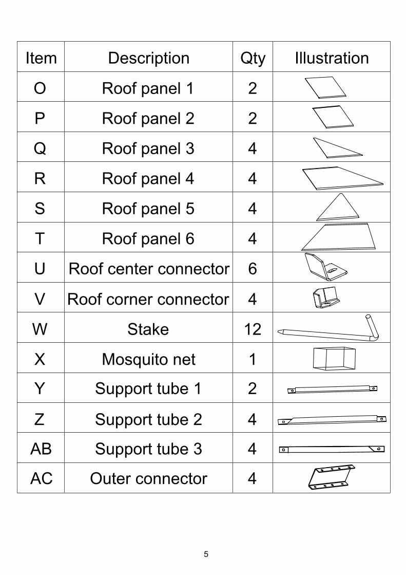
Item Description IllustrationQty
2
2
4
4
4
4
6
4
12
1
O
P
Q
R
S
T
U
V
W
X
Roof panel 1
Roof panel 2
Roof panel 3
Roof panel 4
Roof panel 5
Roof panel 6
Roof center connector
Roof corner connector
Stake
Mosquito net
Y
Z
AB
AC
2
4
4
4
Support tube 1
Support tube 2
Support tube 3
Outer connector

6
Item Description IllustrationQty
106
32
1
AA
BB
CC
Short screw M6 x 15mm
Medium screw M6 x 35mm
Allen wrench
Long screw M6 x 100mm
Bolt nut
Spanner
DD
EE
FF 1
16
16
7
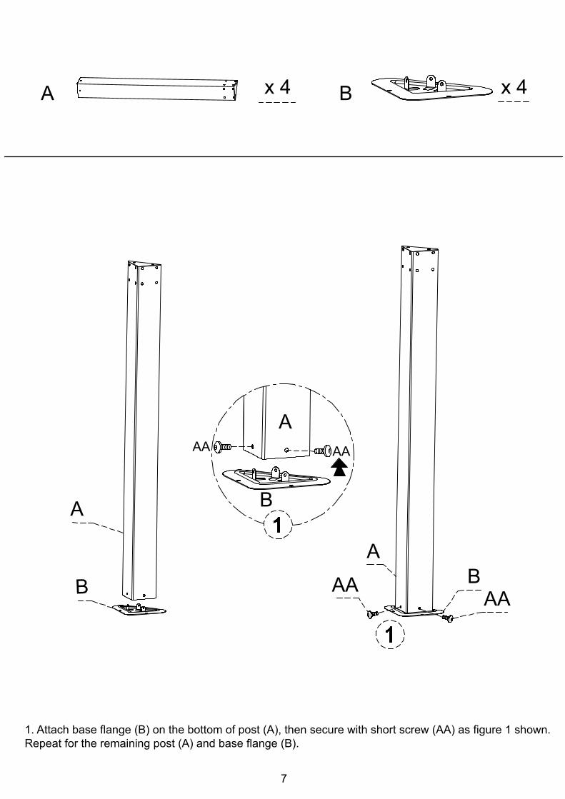
A Bx 4 x 4
A
B
AA
AAA
B
A
AAAA
B
1. Attach base flange (B) on the bottom of post (A), then secure with short screw (AA) as figure 1 shown.Repeat for the remaining post (A) and base flange (B).

8
1. Insert inner connector (E) in between long crossbar 1, 2 (C, D) secure with short screw (AA). See figure 1.2. Secure outer connector (AC) with long crossbar (C, D) using long screw (CC) and bolt nut (DD) as figure 2 shown. 3. Secure center connector (H) onto the long crossbar (C, D) by using short screw (AA) as figure 2 shown.Repeat for remaining long crossbar (C, D).Notes: Please check the upper fig. and make sure all the parts in right position.
D
x 2
x 2
C
3
AA
E x 2
x 4H
AC x 2
33
12
EC
D
HH
2
H
DC
AC
AC
DD
CC
C D
AA
1

9
1. Insert inner connector (E) in between short crossbar 1, 2 (F, G) secure with short screw (AA). See figure 1.2. Secure center connector (H) onto the inner connector (E) by using short screw (AA) as figure 1 shown.3. Secure outer connector (AC) with short corssbar (G, F) by using long screw (CC) and bolt nut (DD) as figure 2 shown.Repeat for remaining short crossbar (F, G).Notes: Please check the upper fig. and make sure all the parts in right position.
F
G
x 2 E x 2
x 2H
F H G
AA
x 2
x 2AC
FG
EH
AC
1
2
2
GFAC
DD
CC
1
10
A
G F 11
1
AA
G
BB BB
BB BB
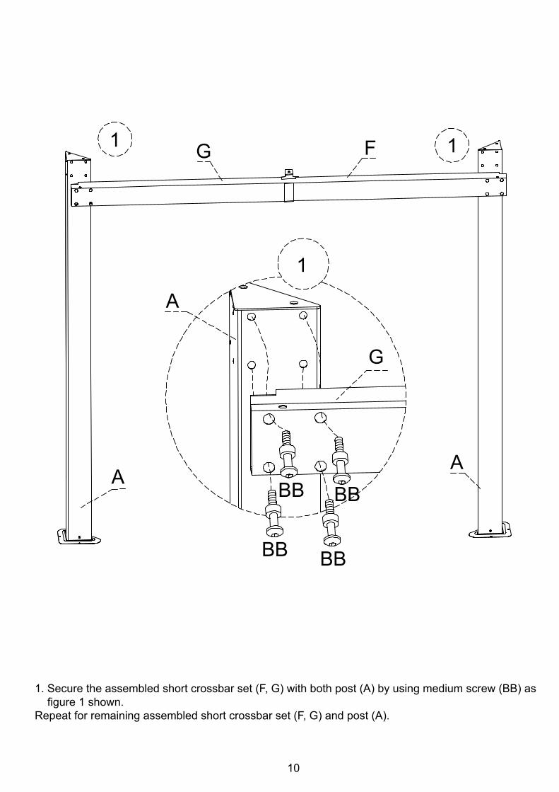
1. Secure the assembled short crossbar set (F, G) with both post (A) by using medium screw (BB) as figure 1 shown.Repeat for remaining assembled short crossbar set (F, G) and post (A).

11
CD
F
GG
F
DC
A
AA
AD
A
BB
F
BB
BBBB
1
11
1
1. Secure the assembled long crossbar set (C, D) with both post (A) by using medium screw (BB) as figure 1 shown.Repeat for remaining assembled long crossbar set (C, D).

12
I x 4
CD
I
I FG I
GF D
C
AA
F
D
1
1
1
I
1
1
1. Secure long crossbar 2 (D) and short crossbar 1 (F) with corner eave connector (I) by using short screw (AA).Repeat for the remaining corner eave connector (I).
I

13
M x 6
1. Use short screw (AA) secure roof connector (J) underneath with short roof tube (M) as figure 1 shown, then insert short screw (AA) through center connector (H) secure with other side of short roof tube (M) as figure 2 shown.Repeat for remaining short roof tube (M).
M
G
F
MM
CD
H
M
H AA
F
G
J1 1
2 22
2
2
M J
M
1
AA
2
14
Lx 4
x 4N
N
L
1
1
N
AA
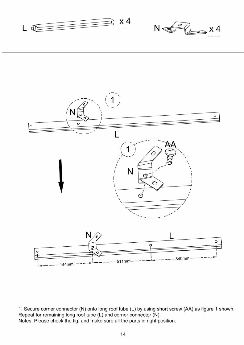
1. Secure corner connector (N) onto long roof tube (L) by using short screw (AA) as figure 1 shown.Repeat for remaining long roof tube (L) and corner connector (N).Notes: Please check the fig. and make sure all the parts in right position.
LN
4mm411mm15
0mm48
15
LJ
L
AA
LJ L
LMMLM
A
AA
A
AN
L
AA
1
212
2
2
2
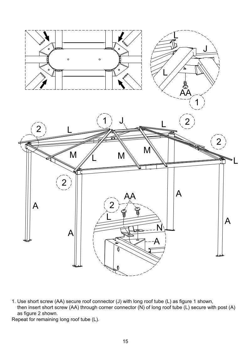
1. Use short screw (AA) secure roof connector (J) with long roof tube (L) as figure 1 shown, then insert short screw (AA) through corner connector (N) of long roof tube (L) secure with post (A) as figure 2 shown.Repeat for remaining long roof tube (L).
16
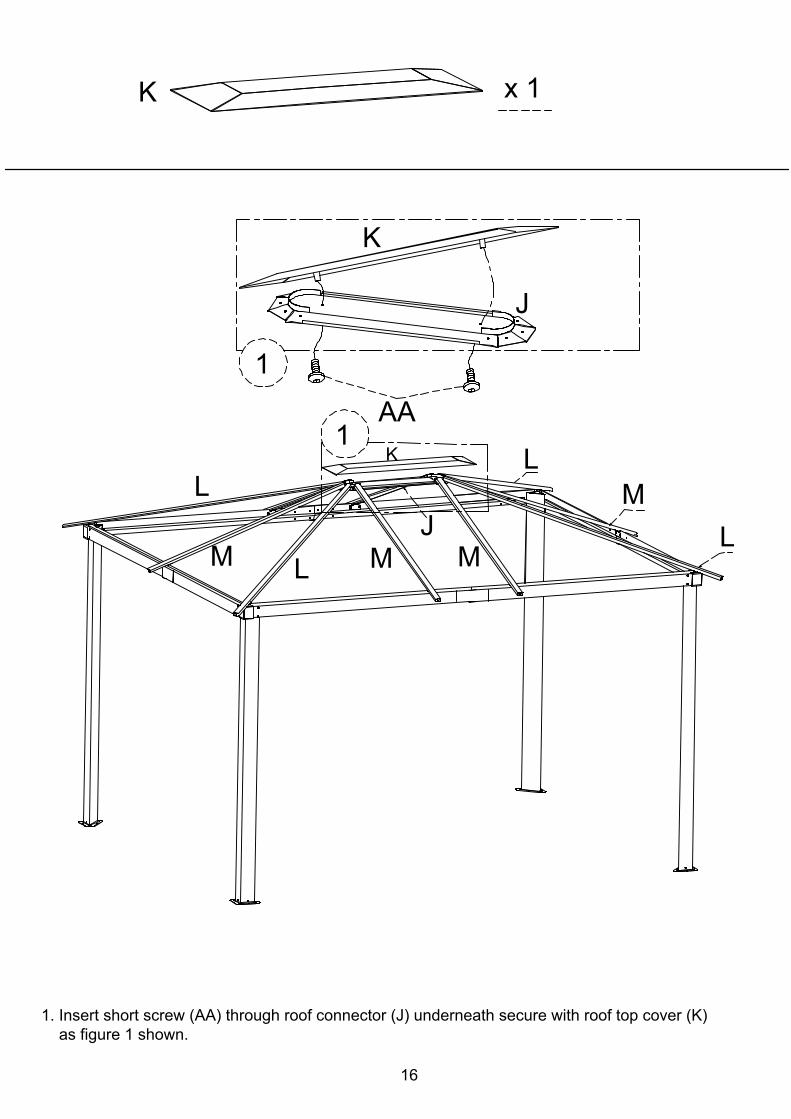
K x 1
K
J
AA
MLLK
LM L M M
1
1
J
1. Insert short screw (AA) through roof connector (J) underneath secure with roof top cover (K) as figure 1 shown.
Y x 2
LZAB
AA
Z x 4
AB x 4
2
Z Y AB
M M
M
ML
L
L
L
BAZ
M
AB
Z
AA1
12
M
Y AB
AA
3
3 32
17
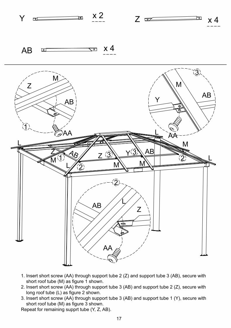
1. Insert short screw (AA) through support tube 2 (Z) and support tube 3 (AB), secure with short roof tube (M) as figure 1 shown.2. Insert short screw (AA) through support tube 3 (AB) and support tube 2 (Z), secure with long roof tube (L) as figure 2 shown.3. Insert short screw (AA) through support tube 3 (AB) and support tube 1 (Y), secure with short roof tube (M) as figure 3 shown.Repeat for remaining supprt tube (Y, Z, AB).

18
O
Q
S
P
R
T
x 2 x 2
x 2
x 2
x 2
x 2
L
SM
M T
T
M
L S
T
LM
L
M
Q
R
M
O
P
S
T
S
T
L
M1
1
1. Peel off the protection sheet from the panel, then insert roof panel 5 (S) into short roof tube (M) and long roof tube (L), then insert roof panel 6 (T) into short roof tube (M) and long roof tube (L) as figure shown.Repeat the step for remaining roof panels (O, P, Q, R, S, T).Caution: Follow the directions of the panel as shown in the diagrams to ensure proper piping. Please do not let the panels slide off.

19
Q
S
R
T
x 2
x 2
x 2
x 2
M SL M
M T
T
M
LR
Q
Q
R
RT
Q s Q
R
O
P
ST
1. Peel off the protection sheet from the panel, then insert roof panel 5 (S) into short roof tube (M) and long roof tube (L), then insert roof panel 6 (T) into short roof tube (M) and long roof tube (L) as figure shown.Repeat the step for remaining roof panels (Q, R, S, T).Caution: Follow the directions of the panel as shown in the diagrams to ensure proper piping. Please do not let the panels slide off.

20
U Vx 6 x 4
M
U
AA
ML
U
L
VU
L
V
AA
12
1
11 2
2
1
2
2
1. Insert short screw (AA) through roof center connector (U) secure with short roof tube (M).2. Insert short screw (AA) through roof corner connector (V) secure with long roof tube (L).Repeat for remaining roof center connector (U) and roof corner connector (V).
21
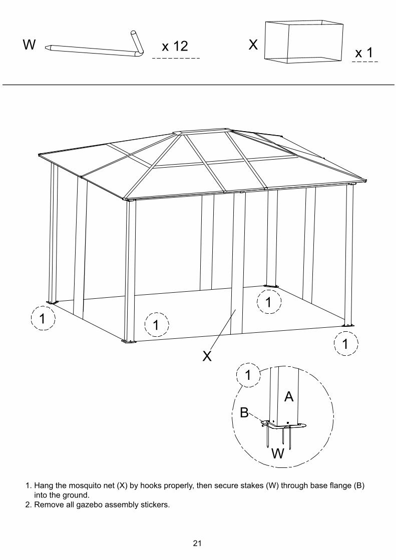
W x 12
B
W
X
1
A
11
1
1
X x 1
1. Hang the mosquito net (X) by hooks properly, then secure stakes (W) through base flange (B) into the ground.2. Remove all gazebo assembly stickers.

Made in / Hecho en CHINA for Kma rt Corporation, Hoffman Estates, IL 60179
For questions or comments about product:Email: [email protected] or Call toll-free: 1-800-961-9838
Please refer to part numbers when reordering
See our extensive assortment of outdoor living productson-line at www .sears.com and www .kmart.com
22
Bond Vast Industrial LimitedBao Tang Industrial Jing LianChiao Tou Town Dong Guang CityGuang Dong ProvinceChina 523 538
USER MAINTENANCE INSTRUCTIONS:
In preparation for winter storage, remove leaves and dirt, dry and wrap inpolybag to prevent rusting.Store in dry place.Treat aluminum fram periodically with liquid wax for maximum protectionagainst UV rays and moisture.Poly nettings clean with a soft brush and lukewarm water, rinse thoroughly.Dry completely.Do not wash with soap as it may remove the protective coatings added by thefactory.