MISSION CONTROL CONCEPTS FOR ROBOTIC OPERATIONS: …
8
MISSION CONTROL CONCEPTS FOR ROBOTIC OPERATIONS: EXISTING APPROACHES AND NEW SOLUTIONS Markus Plura *1 , Heiko M ¨ uller †1 , Martin Stelzer ‡2 , and Florian Sellmaier §3 1 VCS AG, Bochum, Germany 2 DLR Institute of Robotics and Mechatronics, Oberpfaffenhofen, Germany 3 DLR German Space Operations Center, Oberpfaffenhofen, Germany ABSTRACT This paper gives a preliminary overview on activities within the currently ongoing Mission Control Concepts for Robotic Operations (MICCRO) study. The aim of the MICCRO study is to reveal commonali- ties in the operations of past, current and future robotic space missions in order to find an abstract, representa- tive mission control concept applicable to multiple fu- ture missions with robotic systems involved. The exist- ing operational concepts, responsibilities and information flows during the different mission phases are taken into account. A particular emphasis is put on the possible interaction between different autonomous components (on-board and on-ground), their synchronisation and the possi- ble shift of autonomy borders during different mission phases. Key words: MICCRO; Mission Operations; Robotics; Ground Autonomy; SSM. 1. INTRODUCTION For the development of a common concept for mis- sion operations of robotic systems experience in different fields needs to be brought together. Within the project team consisting of the VCS AG, DLR Institute of Robotics and Mechatronics and the German Space Operations Center (GSOC) expertise in robotics, in spacecraft op- erations and ground mounitoring and control (M&C) as well as data distribution systems are combined. Especially for robotic missions, the autonomy aspects need to be analysed. For most space missions the space- craft is designed to operate autonomously for a limited time of appr. 48 hours on a provided schedule. Depend- ing on the nature of the robotic mission the underlying common mission operations concept needs to cope with different needs. When running in a teleoperation mode, the robotic operations requires control within seconds, or in the special case of telepresence within a few millisec- * [email protected] † [email protected] ‡ [email protected] § fl[email protected] onds. On the other hand a rover scenario can introduce requirements for autonmous planning systems e.g. for path finding, etc. Robotic subsystems have been demonstrated in different use cases. During the ROTEX experiment [8] as part of the D-2 mission in 1993 a small 6-axis robot equipped with a 6 degrees of freedom (DOF) wrist-mounted force torque sensor (FTS), laser range finder and video cameras performed about 10 sets of experiments in LEO within 10 days. A number of prototype tasks in different oper- ational modes within the pressurized SpaceLab module were demonstrated. These included direct teleoperation by astronauts on-board with 6 DOF I/O devices, teleop- eration on-board by locally executed sequences of pre- defined commands in automatic mode refined by local sensor data and teleoperation on-board by operator on- ground with time delays in the order of several seconds and autonomous catching of free-flying objects having the ground in the loop. In 1999 DLR’s German Technology Experiment (GE- TEX) [13] operated a 6 DOF robot arm equipped with wrist-mounted FTS and various stereo cameras in LEO on the outside of the Japanese ETS-VII satellite in free space for 15 experiments within a week. The tasks during this mission had been performed using VR methods and the vision&force control scheme, by closing sensor con- trol loops directly on-board (using measured forces) and via the ground track (using vision), thus, proving DLR’s sensor-based autonomy features, verify a 6 DOF dynamic model for the interaction between the robot and its free- flying carrier satellite in free motion mode without AOCS intervention. For the ROKVISS experiment [9] a small 2 DOF manip- ulator equipped with torque sensors, joint-position sen- sors and stereo cameras was mounted outside the Russian Service Module (Zvezda) on ISS in LEO to demonstrate the fitness of DLR’s light weight robotics technology for space between 2005 and 2010. Aims of ROKVISS had been in-flight long term verification of highly integrated modular robot joints developed by DLR, evaluation and monitoring of evolution of dynamical parameters (es- pecially friction, motor constant and stiffness) over the course of the mission in order to validate the long term stability of the system and performance of high-quality telepresence operation including haptic feedback.
Transcript of MISSION CONTROL CONCEPTS FOR ROBOTIC OPERATIONS: …
MISSION CONTROL CONCEPTS FOR ROBOTIC OPERATIONS: EXISTINGAPPROACHES AND NEW SOLUTIONS
Markus Plura∗1, Heiko Muller†1, Martin Stelzer‡2, and Florian Sellmaier§3
1VCS AG, Bochum, Germany2DLR Institute of Robotics and Mechatronics, Oberpfaffenhofen, Germany
3DLR German Space Operations Center, Oberpfaffenhofen, Germany
ABSTRACT
This paper gives a preliminary overview on activitieswithin the currently ongoing Mission Control Conceptsfor Robotic Operations (MICCRO) study.The aim of the MICCRO study is to reveal commonali-ties in the operations of past, current and future roboticspace missions in order to find an abstract, representa-tive mission control concept applicable to multiple fu-ture missions with robotic systems involved. The exist-ing operational concepts, responsibilities and informationflows during the different mission phases are taken intoaccount.A particular emphasis is put on the possible interactionbetween different autonomous components (on-boardand on-ground), their synchronisation and the possi-ble shift of autonomy borders during different missionphases.
Key words: MICCRO; Mission Operations; Robotics;Ground Autonomy; SSM.
1. INTRODUCTION
For the development of a common concept for mis-sion operations of robotic systems experience in differentfields needs to be brought together. Within the projectteam consisting of the VCS AG, DLR Institute of Roboticsand Mechatronics and the German Space OperationsCenter (GSOC) expertise in robotics, in spacecraft op-erations and ground mounitoring and control (M&C) aswell as data distribution systems are combined.Especially for robotic missions, the autonomy aspectsneed to be analysed. For most space missions the space-craft is designed to operate autonomously for a limitedtime of appr. 48 hours on a provided schedule. Depend-ing on the nature of the robotic mission the underlyingcommon mission operations concept needs to cope withdifferent needs. When running in a teleoperation mode,the robotic operations requires control within seconds, orin the special case of telepresence within a few millisec-
∗[email protected]†[email protected]‡[email protected]§[email protected]
onds. On the other hand a rover scenario can introducerequirements for autonmous planning systems e.g. forpath finding, etc.Robotic subsystems have been demonstrated in differentuse cases. During the ROTEX experiment [8] as part ofthe D-2 mission in 1993 a small 6-axis robot equippedwith a 6 degrees of freedom (DOF) wrist-mounted forcetorque sensor (FTS), laser range finder and video camerasperformed about 10 sets of experiments in LEO within10 days. A number of prototype tasks in different oper-ational modes within the pressurized SpaceLab modulewere demonstrated. These included direct teleoperationby astronauts on-board with 6 DOF I/O devices, teleop-eration on-board by locally executed sequences of pre-defined commands in automatic mode refined by localsensor data and teleoperation on-board by operator on-ground with time delays in the order of several secondsand autonomous catching of free-flying objects havingthe ground in the loop.In 1999 DLR’s German Technology Experiment (GE-TEX) [13] operated a 6 DOF robot arm equipped withwrist-mounted FTS and various stereo cameras in LEOon the outside of the Japanese ETS-VII satellite in freespace for 15 experiments within a week. The tasks duringthis mission had been performed using VR methods andthe vision&force control scheme, by closing sensor con-trol loops directly on-board (using measured forces) andvia the ground track (using vision), thus, proving DLR’ssensor-based autonomy features, verify a 6 DOF dynamicmodel for the interaction between the robot and its free-flying carrier satellite in free motion mode without AOCSintervention.For the ROKVISS experiment [9] a small 2 DOF manip-ulator equipped with torque sensors, joint-position sen-sors and stereo cameras was mounted outside the RussianService Module (Zvezda) on ISS in LEO to demonstratethe fitness of DLR’s light weight robotics technology forspace between 2005 and 2010. Aims of ROKVISS hadbeen in-flight long term verification of highly integratedmodular robot joints developed by DLR, evaluation andmonitoring of evolution of dynamical parameters (es-pecially friction, motor constant and stiffness) over thecourse of the mission in order to validate the long termstability of the system and performance of high-qualitytelepresence operation including haptic feedback.

Figure 1. Project Structure
Common to the above mentioned experiments is an in-tegration of the different robotic components into an ex-isting mission concept and by that also existing systeminfrastructures, incl. the spacecraft. The robotic compo-nent was integrated and handled as a payload system. Forfuture systems where the robotic component has a veryclose coupling and interaction with the spacecraft itself,the integration as a payload leads to a number of prob-lems as the satellite platform itself is influenced duringthe robotic operations phase. A new mission operationsconcept is required as an enabler for the implementationof robotic missions.The operational experience from running more than 50space missions in the GSOC [16] over the last 40 yearsamended by the special conclusions drawn from alreadyimplemented missions involving a high degree of auton-omy are used within this project.Finally this knowledge is brought together with the VCSexperience in implementing M&C solutions in the ColCCat the GSOC and also in the Galileo ground segment im-plementing the GACF, CMCF and GNMF elements [17].By that, a deep insight into the control centres and alsothe operational concepts was gained. Interviews withVCS operators working at the European Space Opera-tions Centre (ESOC) allows to compare the concepts asrun in different control centres.The combination of the project team partners allows tocreate an open minded review of the known mission oper-ation concepts and to synthesise a common mission con-cept covering future robotic missions or also missions in-volving autonomous components.
2. PROJECT OBJECTIVES
The project objective is to develop and verify the abovementioned generic mission operation concept that canbe utilised when implementing space missions includ-ing also robotic or autonomous components. The projectstarted end of 2010 running for 24 month and structuresinto two phases as shown in Figure 1.
In phase I Concept Development, the conceptual workfocusses on the review and analysis of past, current andfuture robotic space missions in order to reveal the indi-
vidual needs as well as the commonalities. A general ap-proach is identified as Mission Type Independent CoarseConcept. The coarse concept is later on refined in a Con-cept Consolidation for Mission Type x. Here a specificmission scenario is selected for the refinement.In phase I the focus of the analysis is put on the:
• Autonomy Concept: Describes different implemen-tations of autonomy and provides guidelines whichaspects shall be considered. Services required forthe missions and possible implementations are dis-cussed.
• Operational Organization, Roles and Responsibili-ties Concept: Analyses the integration of the roboticcomponent into the mission infrastructures as wellas the organisational structures and hierarchies.
• Communication Concept: General as well as spe-cific constraints that are introduced by the roboticcomponents are analysed.
• User Concept: Description of the required humanmachine interfaces (HMIs) to operate the roboticmission as a bundle of standardised and also missionor problem specific interfaces.
The concepts developed and documented in phase I areverified in phase II Concept Verification of the project.For this purpose a prototype representing the missiontype that was used for the concept consolidation is usedto achieve the proof of concept.
3. AUTONOMY CONCEPT
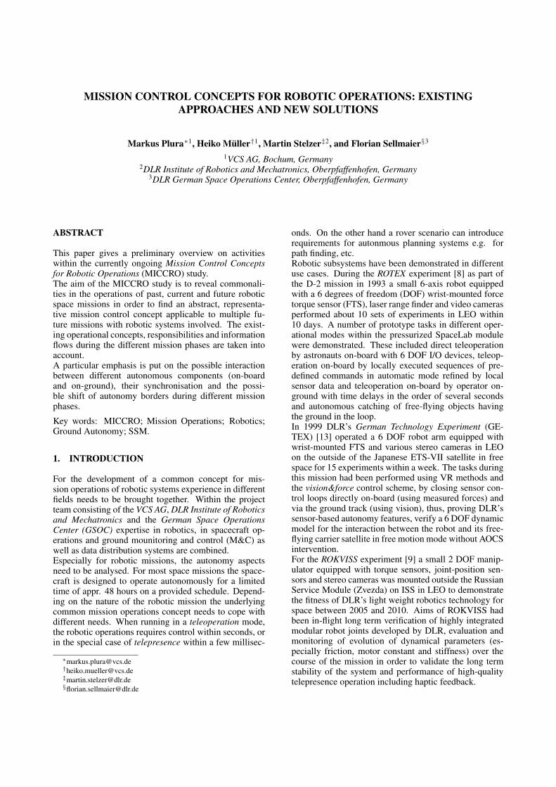
Multiple definitions and classifications for autonomyhave been proposed by different academic disciplines andfor space applications in particular. While some of themfocus on dedicated use cases or foster a close relationbetween planning and autonomy we want to stick to arather comprehensive description where the degree of au-tonomy is determined by the interplay of cerebral andspinal functions in order to achieve a certain task (seeFigure 2).
Spinal vs. Cerebral A spinal function is a highly re-active, reflex like action, e.g. in case of an unexpectedsituation or failure. Spinal functions usually save a sys-tem from bigger damage. Thus FDIR mechanisms of-ten fall into the category of spinal functions. In con-trast to this we define cerebral functions which representlong term strategies. These operate on a larger time scaleand are usually not adequate to solve realtime problems.Talking about architectures spinal and cerebral functionscorrespond to the concept of reactive and deliberativelayers. Both, spinal and cerebral functions are catego-rized by two aspects. The application domain is deter-mined by space specific operations functions like Man-aging, GNC, FDIR, Intelligent Sensing, Data Handlingand M&C (compare to CCSDS 520.0-G-3). Second wedistinguish different technologies used to implement au-tonomous behaviour. These technologies reach from sim-ple time and/or event based automated execution overclassical control engineering and machine learning tech-niques to highlevel planning and scheduling approaches.
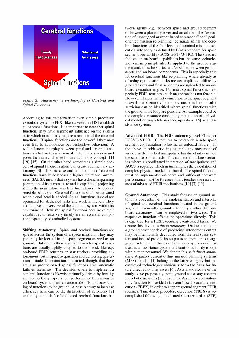
Figure 2. Autonomy as an Interplay of Cerebral andSpinal Functions
According to this categorisation even simple procedureexecution systems (PEX) like surveyed in [18] establishautonomous functions. It is important to note that spinalfunctions may have significant influence on the systemstate which in turn may require a reaction of the cerebralfunctions. If spinal functions are too powerful they mayeven lead to autonomous but destructive behaviour. Awell balanced interplay between spinal and cerebral func-tions is what makes a reasonable autonomous system andposes the main challenge for any autonomy concept [11][19] [15]. On the other hand sometimes a simple con-cert of spinal functions alone can create rudimentary au-tonomy [3]. The increase and combination of cerebralfunctions usually composes a higher situational aware-ness (SA). SA means that a system has a domain spanningperception of its current state and is capable of projectingit into the near future which in turn allows it to deducesensible behaviour. Cerebral functions shall be activatedwhen a cool head is needed. Spinal functions instead areoptimized for dedicated tasks and work in niches. Theydo not have an overview of the complete system within itsenvironment. However, spinal functions because of theircapabilities to react very timely are an essential compo-nent especially of embodied systems.
Shifting Autonomy Spinal and cerebral functions arespread across the system of a space mission. They maygenerally be located in the space segment as well as onground. But due to their reactive character spinal func-tions are usually tightly coupled to their host, like e.g.on-board FDIR routines or star trackers providing au-tonomous lost in space acquisition and delivering quater-nion attitude determination. It is noted, though, that thereare also ground-based spinal functions like automaticfailover scenarios. The decision where to implement acerebral function is likewise primarily driven by localityand connectivity aspects, but performance limitations ofon-board systems often enforce trade-offs and outsourc-ing of functions to the ground. A possible way to increaseefficiency here can be the distribution of autonomy [2]or the dynamic shift of dedicated cerebral functions be-
tween agents, e.g. between space and ground segmentor between a planetary rover and an orbiter. The ”execu-tion of time tagged or event-based commands” and ”goal-oriented mission re-planning” designate spinal and cere-bral functions of the four levels of nominal mission exe-cution autonomy as defined by ESA’s standard for spacesegment operability (ECSS-E-ST-70-11C). The standardfocuses on on-board capabilities but the same technolo-gies can in principle also be applied to the ground seg-ment and, thus, be shifted and/or shared between groundassets and on-board components. This is especially truefor cerebral functions like re-planning where already asof today optimisation tasks are accomplished offline byground assets and final schedules are uploaded to an on-board execution engine. For most spinal functions - es-pecially FDIR routines - such an approach is not feasible.However, if a permanent connection to the space segmentis available, scenarios for robotic missions like on-orbitservicing can be identified where spinal functions withthe ground in the loop are possible. An example could bethe complex, resource consuming simulation of a physi-cal model during a telepresence operation [16] as an as-sistance system.
Advanced FDIR The FDIR autonomy level F1 as perECSS-E-ST-70-11C requires to ”establish a safe spacesegment configuration following an onboard failure”. Inthe above on-orbit servicing example any movement ofan externally attached manipulator has direct influence onthe satellite bus’ attitude. This can lead to failure scenar-ios where a coordinated interaction of manipulator andAOCS is required which in turn implies the calculation ofcomplex physical models on-board. The spinal functionmust be implemented on-board and sufficient hardwareperformance must be foreseen. This touches the researcharea of advanced FDIR mechanisms [10] [7] [12].
Ground Autonomy This study focuses on ground au-tonomy concepts, i.e. the implementation and interplayof spinal and cerebral functions located in the groundsegment. Generally ground autonomy - other than on-board autonomy - can be employed in two ways: Therespective function affects the operations directly. Thisis e.g. true for a PEX executing event-based tasks. Wedenote this flavour as direct autonomy. On the other handa ground asset capable of producing autonomous outputmay be intentionally decoupled from the real space sys-tem and instead provide its output to an operator as a sug-gested solution. In this case the autonomy component isused as an assistance system and control authority is keptwith human personnel. We denote this as indirect auton-omy. Arguably current offline mission planning systems(MPS) like [1] [4] belong to the latter category but theemployed technologies obviously form the basis for fu-ture direct autonomy assets [6]. As a first outcome of theanalysis we propose a generic ground autonomy conceptfor robotic missions (see Figure 3). A spinal direct auton-omy function is provided via event-based procedure exe-cution (EBEX) in order to support ground segment FDIRroutines. Time-based procedure execution (TBEX) is ac-complished following a dedicated short term plan (STP)
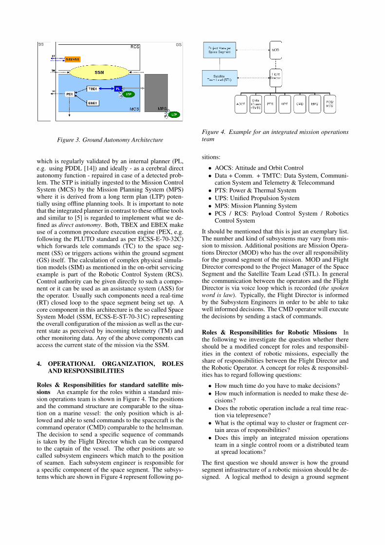
Figure 3. Ground Autonomy Architecture
which is regularly validated by an internal planner (PL,e.g. using PDDL [14]) and ideally - as a cerebral directautonomy function - repaired in case of a detected prob-lem. The STP is initially ingested to the Mission ControlSystem (MCS) by the Mission Planning System (MPS)where it is derived from a long term plan (LTP) poten-tially using offline planning tools. It is important to notethat the integrated planner in contrast to these offline toolsand similar to [5] is regarded to implement what we de-fined as direct autonomy. Both, TBEX and EBEX makeuse of a common procedure execution engine (PEX, e.g.following the PLUTO standard as per ECSS-E-70-32C)which forwards tele commands (TC) to the space seg-ment (SS) or triggers actions within the ground segment(GS) itself. The calculation of complex physical simula-tion models (SIM) as mentioned in the on-orbit servicingexample is part of the Robotic Control System (RCS).Control authority can be given directly to such a compo-nent or it can be used as an assistance system (ASS) forthe operator. Usually such components need a real-time(RT) closed loop to the space segment being set up. Acore component in this architecture is the so called SpaceSystem Model (SSM, ECSS-E-ST-70-31C) representingthe overall configuration of the mission as well as the cur-rent state as perceived by incoming telemetry (TM) andother monitoring data. Any of the above components canaccess the current state of the mission via the SSM.
4. OPERATIONAL ORGANIZATION, ROLESAND RESPONSIBILITIES
Roles & Responsibilities for standard satellite mis-sions An example for the roles within a standard mis-sion operations team is shown in Figure 4. The positionsand the command structure are comparable to the situa-tion on a marine vessel: the only position which is al-lowed and able to send commands to the spacecraft is thecommand operator (CMD) comparable to the helmsman.The decision to send a specific sequence of commandsis taken by the Flight Director which can be comparedto the captain of the vessel. The other positions are socalled subsystem engineers which match to the positionof seamen. Each subsystem engineer is responsible fora specific component of the space segment. The subsys-tems which are shown in Figure 4 represent following po-
Figure 4. Example for an integrated mission operationsteam
sitions:
• AOCS: Attitude and Orbit Control• Data + Comm. + TMTC: Data System, Communi-
cation System and Telemetry & Telecommand• PTS: Power & Thermal System• UPS: Unified Propulsion System• MPS: Mission Planning System• PCS / RCS: Payload Control System / Robotics
Control System
It should be mentioned that this is just an exemplary list.The number and kind of subsystems may vary from mis-sion to mission. Additional positions are Mission Opera-tions Director (MOD) who has the over all responsibilityfor the ground segment of the mission. MOD and FlightDirector correspond to the Project Manager of the SpaceSegment and the Satellite Team Lead (STL). In generalthe communication between the operators and the FlightDirector is via voice loop which is recorded (the spokenword is law). Typically, the Flight Director is informedby the Subsystem Engineers in order to be able to takewell informed decisions. The CMD operator will executethe decisions by sending a stack of commands.
Roles & Responsibilities for Robotic Missions Inthe following we investigate the question whether thereshould be a modified concept for roles and responsibil-ities in the context of robotic missions, especially theshare of responsibilities between the Flight Director andthe Robotic Operator. A concept for roles & responsibil-ities has to regard following questions:
• How much time do you have to make decisions?• How much information is needed to make these de-
cisions?• Does the robotic operation include a real time reac-
tion via telepresence?• What is the optimal way to cluster or fragment cer-
tain areas of responsibilities?• Does this imply an integrated mission operations
team in a single control room or a distributed teamat spread locations?
The first question we should answer is how the groundsegment infrastructure of a robotic mission should be de-signed. A logical method to design a ground segment

infrastructure is to mirror the space segment structure re-garding functionalities and interfaces. The ground seg-ment infrastructure should minimize the complexity ofinterfaces between distributed components. Usually it isa good idea to operate the robotic payload and the spacevessel it is mounted on within an integrated operationsteam since the robotic system heavily interacts with thespacecraft. Examples are the operation of a rover or anOn-Orbit Servicing mission like DEOS. An exception isthe operation of the robotic experiment ROKVISS on theISS where the interaction between the robotic manipu-lator of ROKVISS and the ISS is negligible. Wheneverthe robotic system and the spacecraft platform are op-erated by an integrated operations team the robotic con-trol system RCS should be integrated like an extendedpayload control system (see Figure 4). However, whentelepresence and real time operations are required a newdimension is introduced into space operations. For non-robotic missions the time scale for decision taking is usu-ally hours or minutes. On the other hand the requirementfor telepresence conditions is to limit the response time toa few hundred milliseconds. Therefore, the standard wayof commanding by voice loop from the Robotic Operatorto the Flight Director to the CMD operator has to be mod-ified. A direct control loop between the robotic system inspace and the robotic payload operator has to be intro-duced. During a robotic phase the communication linkis shifted from the standard link to a telepresence link.At the same time the control authority is be shifted fromthe command operator to the robotic operator (CMD andRCS positions within Figure 4).
Control vs. Responsibilities Contrary to the controlauthority responsibilities should be never shifted: TheFlight Director will always be responsible for the com-plete system; a subsystem operator will always have theresponsibility for his subsystem. In certain phases thiseven implies that e.g. the AOCS subsystem engineer isresponsible to keep the AOCS deactivated. The share ofresponsibilities between Flight Director and Robotic Op-erator are similar to the roles of a Shuttle commander andpilot: The robotic operator has the control authority ontime scales of milliseconds whereas the Flight Director isresponsible for the overview and general decisions on atime scale of seconds and minutes which includes a pos-sible decision to abort a robotic operation. The procedurehow to abort robotic operations depends on the situationand phase. It should be predefined and trained as muchas possible.
5. COMMUNICATION CONCEPT
For space missions the communication infrastructure is akey component. Therefore, the communication conceptfor robotic missions describes the general contraints in-fluencing the concept and introduces and details the spe-cific demands induced by the robotic components.
General Constraints Cost induces financial con-straints for space missions and this holds especially truefor the ground segment with its ground station network.
Carrying out the routine phase of a space mission isalways a compromise between a higher degree of on-board autonomy or robustness and the number of (costly)ground station contacts to control the spacecraft. For al-most all national security-related missions, the groundsegment with its control center and ground stations is re-stricted to be located within the country of the owner ofthe satellite (political constraint). Different criteria in-ducing connectivity constraints, the bandwidth, latencytime and a third one, which is protocol need to be deeplyanalysed. Effective scheduling of the customers requestsfor satellite contacts is the key to running a ground sta-tion economically successfull. To reduce schedule prob-lems and also to use support equipment and facilities thatare needed to operate an antenna more efficiently, groundstation support providers often build more than one an-tenna per ground station. The antenna availability con-straints depending on the ground station schedule priori-sation needs to be considered. The involved ground sta-tion and the control centre must support the encryptionstandard required by the mission (security constraints).If special hardware must be used or modifications to theground station equipment must be carried out, the num-ber of potentially usable ground stations is limited to spe-cial ground stations run by national services, e.g. armedforces or intelligence services. The space segment needsto satisfy a number of mission specific communicationrelated requirements, which induces space segment con-straints. These can not be described in advance as itstrongly depends on the communication path and possi-ble other spacecrafts.
Robotic Constraints Future activities in space will bemore and more complemented by robotic support. Re-mote control concepts which rely on system access viateleoperation have already been used in the past [8] [13].This operation mode allows just a delayed access to anapplication in space. The commanding for each processstep has to be identified in advance in order to assemblea script-like to-do list. A typical but normally not time-critical mission control service in that context is the man-agement of uplinking those robotic scripts to and down-linking stored results from the spacecraft. Direct inter-action especially in case of any contingency is impossi-ble. On the one hand such a static operation concept iswithout any alternative in case of having strict temporaryrequirements or bridging great distances (e.g. deep spacemissions or planetary exploration). On the other handits static nature shortens the flexibility required for directservicing (e.g. in earth orbit). A concept to overcome thatlethargical behaviour is telepresence, where the physicalcorrelation between actio and reactio is directly fed backto the operator. This allows for a highly flexible han-dling of the current situation (especially useful for ser-vicing and repairing). From its basic nature telepresenceis a distributed control loop imposing harder constraintson the communication link compared to teleoperation.From a robotic point of view a communication link ischaracterised by bandwidth, jitter, latency, reliability oftransmission, duration of radio contact and signal propa-gation time. Each of them has direct impact on the quality
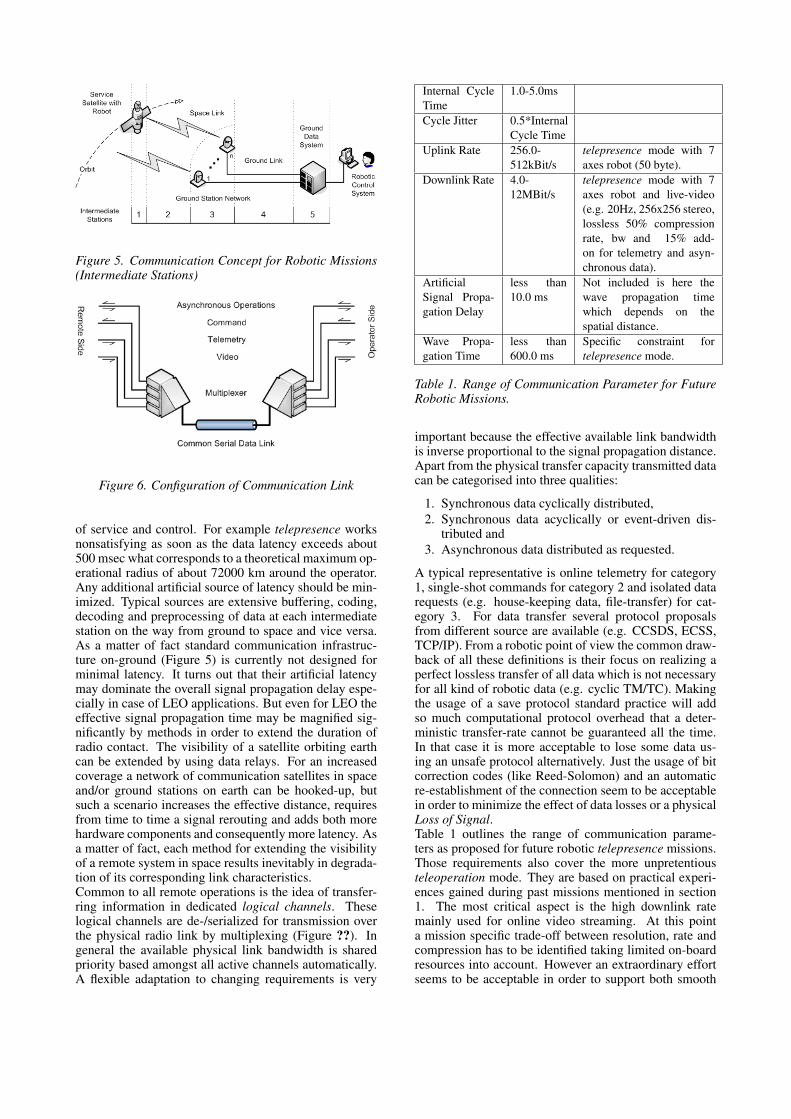
Figure 5. Communication Concept for Robotic Missions(Intermediate Stations)
Figure 6. Configuration of Communication Link
of service and control. For example telepresence worksnonsatisfying as soon as the data latency exceeds about500 msec what corresponds to a theoretical maximum op-erational radius of about 72000 km around the operator.Any additional artificial source of latency should be min-imized. Typical sources are extensive buffering, coding,decoding and preprocessing of data at each intermediatestation on the way from ground to space and vice versa.As a matter of fact standard communication infrastruc-ture on-ground (Figure 5) is currently not designed forminimal latency. It turns out that their artificial latencymay dominate the overall signal propagation delay espe-cially in case of LEO applications. But even for LEO theeffective signal propagation time may be magnified sig-nificantly by methods in order to extend the duration ofradio contact. The visibility of a satellite orbiting earthcan be extended by using data relays. For an increasedcoverage a network of communication satellites in spaceand/or ground stations on earth can be hooked-up, butsuch a scenario increases the effective distance, requiresfrom time to time a signal rerouting and adds both morehardware components and consequently more latency. Asa matter of fact, each method for extending the visibilityof a remote system in space results inevitably in degrada-tion of its corresponding link characteristics.Common to all remote operations is the idea of transfer-ring information in dedicated logical channels. Theselogical channels are de-/serialized for transmission overthe physical radio link by multiplexing (Figure ??). Ingeneral the available physical link bandwidth is sharedpriority based amongst all active channels automatically.A flexible adaptation to changing requirements is very
Internal CycleTime
1.0-5.0ms
Cycle Jitter 0.5*InternalCycle Time
Uplink Rate 256.0-512kBit/s
telepresence mode with 7axes robot (50 byte).
Downlink Rate 4.0-12MBit/s
telepresence mode with 7axes robot and live-video(e.g. 20Hz, 256x256 stereo,lossless 50% compressionrate, bw and 15% add-on for telemetry and asyn-chronous data).
ArtificialSignal Propa-gation Delay
less than10.0 ms
Not included is here thewave propagation timewhich depends on thespatial distance.
Wave Propa-gation Time
less than600.0 ms
Specific constraint fortelepresence mode.
Table 1. Range of Communication Parameter for FutureRobotic Missions.
important because the effective available link bandwidthis inverse proportional to the signal propagation distance.Apart from the physical transfer capacity transmitted datacan be categorised into three qualities:
1. Synchronous data cyclically distributed,2. Synchronous data acyclically or event-driven dis-
tributed and3. Asynchronous data distributed as requested.
A typical representative is online telemetry for category1, single-shot commands for category 2 and isolated datarequests (e.g. house-keeping data, file-transfer) for cat-egory 3. For data transfer several protocol proposalsfrom different source are available (e.g. CCSDS, ECSS,TCP/IP). From a robotic point of view the common draw-back of all these definitions is their focus on realizing aperfect lossless transfer of all data which is not necessaryfor all kind of robotic data (e.g. cyclic TM/TC). Makingthe usage of a save protocol standard practice will addso much computational protocol overhead that a deter-ministic transfer-rate cannot be guaranteed all the time.In that case it is more acceptable to lose some data us-ing an unsafe protocol alternatively. Just the usage of bitcorrection codes (like Reed-Solomon) and an automaticre-establishment of the connection seem to be acceptablein order to minimize the effect of data losses or a physicalLoss of Signal.Table 1 outlines the range of communication parame-ters as proposed for future robotic telepresence missions.Those requirements also cover the more unpretentiousteleoperation mode. They are based on practical experi-ences gained during past missions mentioned in section1. The most critical aspect is the high downlink ratemainly used for online video streaming. At this pointa mission specific trade-off between resolution, rate andcompression has to be identified taking limited on-boardresources into account. However an extraordinary effortseems to be acceptable in order to support both smooth

stereoscopic real-time visualisation and high-resolutionimage processing on-ground.
6. USER CONCEPT
The user concept is driven by two main aspects which arethe operational organzisation, roles and responsibilities,which have been discussed before and the HMI concept.The latter one will be discussed in this section.SCOS-2000 and the VCS egmc2 framework providewell-proven HMIs that have been used successfully tosupport spacecraft missions. If robotic components areinvolved in a mission, these interfaces can still serve theirpurpose and, thus, may be used as a starting point fromwhich robotic features can be integrated once they are de-manded.Missions characterized by long transmission time delaysor high autonomy levels on-board will generally rise lessdemands on robotics and MCS integration. Coupling ofthe MCS and the robotics control may then be realizedloosely allowing every party to perform their duties moreor less independent from each other. However, new chal-lenges arise when it comes to direct operation of satel-lite based robots from ground (close coupling). Effi-cient flight operations structures and highly intuitive in-terfaces must enable quick and correct decision makingthen. Therefore, robotics needs to be tightly and seam-lessly integrated into the MCS. Thus, we choose to inte-grate the robotic operations analogous to operations forother satellite subsystems into the same control room us-ing similar control structures and user interfaces.Generally, there are three categories of data which needto be presented to human operators through their HMI:
• Satellite uplink/downlink data including conven-tional command and telemetry data as well as datatransmitted through realtime channels
• Data exchanged between operators and other on-ground applications such as ground data, ground au-tonomy, video processing and similar assistance ap-plications
• Management and status data for all ground facilitiesincluding means to start, stop, reset and supervisethese systems
These data should be visualized through HMI compo-nents which plug into a standardized application frame-work (Figure 7). The composition of these componentsvaries with respect to the responsibilities of the particularoperator, whereas some components may be repeatedlyused for several or all interfaces.From experiences gathered during past missions the fol-lowing requirements from the robotics viewpoint havebeen compiled:
• The user interfaces for the robot operators shouldcomply with high level software ergonomics stan-dards. This respects the task complexity and heavyresponsibility of the operator actually guiding therobot.
• For the same sake the robotics operator should beprovided an augmented virtual reality display of the
Figure 7. Example: egmc2 User Interface Framework
Figure 8. Augmented Reality Interface
situation on-board the spacecraft. Such an interfacecomprises a 3D graphics visualization augmentedwith key values and hints such as force measure-ments and planned access pathways (see Figure 8).
• HMI components common to all robotics teammembers should comprise a state summary of theoverall systems on-ground, on-board and a more de-tailed summary of the robotics subsystem.
• A mission timeline should depict planned and actualprocedures and events.
• A video display should alleviate imagination of thesituation on-board for all robotics team members.
• High-end haptic input devices should enable therobotics operator to actually feel what is going onon-board during telepresent manipulation.
7. CONCEPT VERIFICATION
The concept that is developed and refined for a selectedmission type during the first 12 month is afterwards ver-ified in a prototype implementation. The selected mis-

sion type is agreed to be an on-orbit servicing missionincorporating robotic manipulators on-board the space-craft. This special scenario has been selected as it in-duces a number of challenging requirements in all areasdiscussed in this paper and by that allows to demonstratemost aspects of the common mission operations concept.The prototype will allow to demonstrate all main con-cepts and innovations identified.
8. CONCLUSION AND OUTLOOK
Future missions involving robotic components as key el-ements require to develop new common mission controlconcepts. This is in particular driven by the close cou-pling and interaction of the robot with the satellite bus it-self, which induced new challenges. Apart from the tech-nical aspects like communication, user interfaces and au-tonomy also the more organisational aspects focussing one.g. roles and responsibilities need to be changed, whenhaving in mind operational concepts as used for standardspacecraft missions.The study provides a common guideline for the imple-mentation of future robotic mission concepts. Using thiscommon concept can save costs as main concepts or com-ponents can be reused across different missions.
ACKNOWLEDGMENTS
The MICCRO project is funded by the Space Agency ofthe German Aerospace Centre (DLR) with federal fundsfrom the Federal Ministry of Economics and Technol-ogy in accordance with the parliamentary resolution ofthe German Parliament (Grant ID 50 RA 1015 and GrantID 50 RA 1016).
REFERENCES
[1] M. Ai-Chang, J. Bresina, K. Farrell, J. Hsu,A. Jonsson, B. Kanefsky, M. McCurdy, P. Morris,K. Rajan, A. Vera, et al. MAPGEN: Mixed InitiativeActivity Planning for the Mars Exploration RoverMission. In Proceedings of the 13th InternationalConference on Planning & Scheduling (ICAPS03),Trento, Italy, 2003.
[2] F. Amigoni, A. Brambilla, M. Lavagna, R. Blake,I. le Duc, J. Page, O. Page, S. de la Rosa Steinz,R. Steel, and Q. Wijnands. Agent Technologies forSpace Applications: The DAFA Experience. 2010.
[3] V. Braitenberg. Vehicles: Experiments in syntheticpsychology. The MIT press, 1986.
[4] A. Cesta, S. Fratini, A. Oddi, and F. Pecora. APSICase# 1: Pre-planning Science Operations in MarsExpress. Proc. of iSAIRAS-08, 2008.
[5] Caroline Chouinard, Russell Knight, GrailingJones, and Daniel Tran. An ASPEN Application:Automating Ground Operations for Orbital Express.In SPARK08. Scheduling and Planning ApplicationsWorkshop at ICAPS. Citeseer, 2008.
[6] A. Donati. Infusion of innovative technologies formission operations. Acta Astronautica, 2010.
[7] A. Guiotto, A. Martelli, and C. Paccagnini.SMART-FDIR: Use of Artificial Intelligence in theImplementation of a Satellite FDIR. In DASIA2003, volume 532, page 71, 2003.
[8] G. Hirzinger, B. Brunner, J. Dietrich, and J. Heindl.Sensor-based space robotics-ROTEX and its teler-obotic features. Robotics and Automation, IEEETransactions on, 9(5):649–663, 1993.
[9] G. Hirzinger, K. Landzettel, D. Reintsema,C. Preusche, A. Albu-Schaffer, B. Rebele, andM. Turk. ROKVISS–Robotics component verifica-tion on ISS. In Proc. of ’The 8th Int. Symposiumon Artifical Intelligence, Roboticsand Automationin Space iSAIRAS, Munich, Germany, 2005.
[10] N. Holsti and M. Paakko. Towards Advanced FDIRComponents. Data Systems in Aerospace, DASIA2001, 2001.
[11] R. Knight, F. Fisher, T. Estlin, B. Engelhardt, andS. Chien. Balancing deliberation and reaction, plan-ning and execution for space robotic applications. InInternational Conference on Intelligent Robots andSystems (IROS 2001), Maui, HI. Citeseer, 2001.
[12] J. Kurien and M.D. R-Moreno. Why Model BasedDiagnosis for Spacecraft Never Took Off. 2008.
[13] K. Landzettel, B. Brunner, K. Deutrich,G. Hirzinger, G. Schreiber, and BM Stein-metz. DLRs Experiments on the ETS-VII SpaceRobot Mission. In 9th International Conference onAdvanced Robotics (ICAR99), Tokyo, 1999.
[14] R.H.D. Long and M. Fox. Plan validation andmixed-initiative planning in space operations. Plan-ning, scheduling and constraint satisfaction: fromtheory to practice, page 89, 2005.
[15] C. McGann, F. Py, K. Rajan, H. Thomas, R. Hen-thorn, and R. McEwen. T-rex: A model-based ar-chitecture for auv control. In 3rd Workshop on Plan-ning and Plan Execution for Real-World Systems,volume 2007. Citeseer, 2007.
[16] F. Sellmaier, T. Boge, J. Spurmann, T. Gully,T. Rupp, and F Huber. On-Orbit Servicing Mis-sions: Challenges and Solutions for Spacecraft Op-erations. In Proc. SpaceOps 2010, 2010.
[17] C. Stocker and I. le Duc. Ground Segment AssetControl with Software Frameworks. In Proceedingsof the SpaceOps 2006, AIAA-2006-5752, Publishedby AIAA, 2006.
[18] V. Verma, A. Jonsson, R. Simmons, T. Estlin, andR. Levinson. Survey of command execution sys-tems for NASA spacecraft and robots. In Plan Ex-ecution: A Reality Check Workshop at the Inter-national Conference on Automated Planning andScheduling (ICAPS). Citeseer, 2005.
[19] R. Volpe, I. Nesnas, T. Estlin, D. Mutz, R. Petras,and H. Das. The CLARAty architecture for roboticautonomy. In Aerospace Conference, 2001, IEEEProceedings., volume 1, page 1. IEEE, 2002.