MISB ST 1101 STANDARD 23 October 2014 Imagery …gwg.nga.mil/misb/docs/standards/ST1101.pdf · ST...
32
23 October 2014 Motion Imagery Standards Board 1 STANDARD STANAG 4586 Control of UAS Motion Imagery Payloads MISB ST 1101 23 October 2014 1 Scope This Standard (ST) provides guidance for the control of Motion Imagery (MI) payloads on a platform, such as an Unmanned Aerial System (UAS). Emphasis is given to Large Volume Motion Imagery (LVMI) payloads, but this guidance applies as well to Ultra High Definition (UHD), High Definition (HD), and Enhanced Definition (ED) payloads. Specifically, this document references a set of control messages for directing a Motion Imagery sensor, extracting a region-of-interest view, and selecting the format for delivery to a ground receiver. The control messages referenced here are published in NATO STANAG 4586 [1] and Army UAS Program Office’s (PO) Private Messages Interface Control Document (PM ICD) [2]. STANAG 4586 is the NATO specification for control of UAS platforms and their payloads, which may include MI sensors, SAR sensors, communications equipment, laser designators, weapons, etc. The PM ICD is a controlled set of extension messages to STANAG 4586, which is maintained and managed by the U.S. Army. The PM ICD evolves more quickly than STANAG 4586 with PM ICD messages eventually propagating to future versions of STANAG 4586. This document does not address platform control, communications control, etc. The messages referenced in this Standard have been accepted into the PM ICD, where they are normative. Appendix A lists these messages and their fields for convenience and as informative only. Appendix B lists messages under consideration by PM ICD, but not yet adopted. Appendix C provides examples of a virtual sensor. 2 References 2.1 Normative References The following references and the references contained therein are normative. [1] NATO STANAG 4586 Edition 2, Amendment 2, Nov 2007 [2] Army IOP PM ICD Version 3.0.2, Feb 2014 [3] MISB MISP 2015.1, Motion Imagery Standards Profile, Oct 2014 [4] MISB ST 0902.3, Motion Imagery Sensor Minimum Metadata Set, Feb 2014 [5] NATO STANAG 4609, Edition 3, Dec 2009
Transcript of MISB ST 1101 STANDARD 23 October 2014 Imagery …gwg.nga.mil/misb/docs/standards/ST1101.pdf · ST...

23 October 2014 Motion Imagery Standards Board 1
STANDARD
STANAG 4586 Control of UAS Motion Imagery Payloads
MISB ST 1101
23 October 2014
1 Scope
This Standard (ST) provides guidance for the control of Motion Imagery (MI) payloads on a
platform, such as an Unmanned Aerial System (UAS). Emphasis is given to Large Volume
Motion Imagery (LVMI) payloads, but this guidance applies as well to Ultra High Definition
(UHD), High Definition (HD), and Enhanced Definition (ED) payloads. Specifically, this
document references a set of control messages for directing a Motion Imagery sensor, extracting
a region-of-interest view, and selecting the format for delivery to a ground receiver.
The control messages referenced here are published in NATO STANAG 4586 [1] and Army
UAS Program Office’s (PO) Private Messages Interface Control Document (PM ICD) [2].
STANAG 4586 is the NATO specification for control of UAS platforms and their payloads,
which may include MI sensors, SAR sensors, communications equipment, laser designators,
weapons, etc. The PM ICD is a controlled set of extension messages to STANAG 4586, which is
maintained and managed by the U.S. Army. The PM ICD evolves more quickly than STANAG
4586 with PM ICD messages eventually propagating to future versions of STANAG 4586. This
document does not address platform control, communications control, etc.
The messages referenced in this Standard have been accepted into the PM ICD, where they are
normative. Appendix A lists these messages and their fields for convenience and as informative
only. Appendix B lists messages under consideration by PM ICD, but not yet adopted. Appendix
C provides examples of a virtual sensor.
2 References
2.1 Normative References
The following references and the references contained therein are normative.
[1] NATO STANAG 4586 Edition 2, Amendment 2, Nov 2007
[2] Army IOP PM ICD Version 3.0.2, Feb 2014
[3] MISB MISP 2015.1, Motion Imagery Standards Profile, Oct 2014
[4] MISB ST 0902.3, Motion Imagery Sensor Minimum Metadata Set, Feb 2014
[5] NATO STANAG 4609, Edition 3, Dec 2009
ST 1101 STANAG 4586 Control of Motion Imagery Payloads
23 October 2014 Motion Imagery Standards Board 2
2.2 Informative References
[6] MISB RP 1011.1, LVSD Motion Imagery Streaming, Feb 2014
[7] MISP RP 0904.1, H.264 Bandwidth/Quality/Latency Tradeoffs, Feb 2014
3 Acronyms
bps bits per second
CUCS Core UAV Control System – the 4586 client
DLI Data Link Interface
ED Enhanced Definition
ES Elementary Stream
HD High Definition
HP High Profile
FOV Field of View
FPS Frames per Second
GOP Group of Pictures
IP Internet Protocol
LVMI Large Volume Motion Imagery.
MI Motion Imagery
ML Main Level
MP Main Profile
RTP Real Time Transport
RVT Remote Video Terminal
TS MPEG-2 Transport Stream
UAS Unmanned Aerial System
UDP User Datagram Protocol
VSM Vehicle Specific Module
4 Definitions
LVMI Applies to systems which collect large imagery – on the order of 100 to
1000 Megapixels/image. LVMI systems typically acquire imagery greater
than one frame-per-second and may operate for hours at a time. These
systems are also known as WALF (Wide Area Large Format), WAAS
(Wide Area Aerial Surveillance), WAMI (Wide Area Motion Imagery),
WAPS (Wide Area Persistent Surveillance), etc.
MISP compliant
Motion Imagery
Data
Data types of Motion Imagery, Metadata and Audio wherein all data types
and container encapsulations comply with MISP Requirements and
Standards.
ST 1101 STANAG 4586 Control of Motion Imagery Payloads
23 October 2014 Motion Imagery Standards Board 3
5 Revision History
Revision Date Summary of Changes
Initial 10/23/2014 First non-draft version. Synchronized with USA IOP 3.0.2
6 Introduction
This document specifies requirements for the control of a Motion Imagery payload, specifically
for LVMI Motion Imagery region-of-interest processes. However, all messages and functionality
are appropriate for any MI sensor that supports STANAG 4586 and PM ICD messages. As used
here, a “window” is a region-of-interest extracted from a larger Motion Imagery field-of-view;
typically, a window is formatted as Enhanced or High Definition Motion Imagery for delivery to
a receiver, although other formats are supported. Also known as a soda-straw view or chip-out, a
window is compliant with MISP standards and requirements. Other LVMI aspects, such as full
field-of-view file formats, archiving of LVMI data, etc. are not discussed here.
NATO STANAG 4586 defines messages for command and control between a UAS and Ground
Station or Remote Video Terminal (RVT). Each message has a fixed-field format. A subset of
these messages is for controlling a Motion Imagery sensor/payload. As an extension to 4586,
additional messages have been added to the Army PM ICD to accommodate the special needs of
LVMI payloads, although these can be used for other Motion Imagery payloads as well. This
document describes the purpose and functionality of these messages.
STANAG 4586 does not, in general, define error messages. Rather, many messages work as
pairs with a request status and response. Typically, a request is made to change a parameter or
initiate an action. The response indicates updated post-request status. If a platform or payload
receives a request outside of its capability, rather than return an error a best effort approximation
of what was requested is made, and the response/status message indicates the action taken. For
example, if a Motion Imagery sensor is capable of producing a maximum of 30 Frames per
Second (FPS) and is issued a request for 60 FPS, the status response will simply indicate 30 FPS,
since that is the nearest supported capability.
Motion Imagery payload products are expected to be MISP compliant. 4586 messages do,
however, permit the request of Motion Imagery in non-compliant formats, such as Motion-JPEG.
Requirement(s)
ST 1101-01 In the default mode, a Motion Imagery payload shall produce MISP-compliant Motion Imagery Data [3].
Notes on messages:
Messages are defined in STANAG 4609[1] and PM ICD [2], which are the normative references
for all messages discussed in this document. Messages added to PM ICD that support the
functionally of this Standard are listed in Appendix A of this document; these are informative
only and are only provided for convenient reference. Any use of these messages should refer to
[1][2] to assure accuracy. Finally, only those messages introduced into the PM ICD that support
the functionality described in this document are indicated in the following message diagrams.

ST 1101 STANAG 4586 Control of Motion Imagery Payloads
23 October 2014 Motion Imagery Standards Board 4
Other LVMI aspects, such as full field-of-view file formats, archiving of LVMI data, etc. are not
discussed in this document.
7 Sensor Addressing and Discovery
Each STANAG 4586 or PM ICD message directed to/from a payload, as opposed to the platform
itself, contains a field called “Station Number” (used interchangeably in 4586). This designates
a specific physical payload, from among those possible, that a message affects.
Requirement(s)
ST 1101-02 All Motion Imagery payload messages shall contain the STANAG 4586 [1] field “Station Number”.
A physical LVMI sensor produces high pixel-density Motion Imagery generally undeliverable
using conventional transmission methods. Within the LVMI field-of-view, extracted windows of
Motion Imagery formatted to meet a constrained channel can be delivered as separate MI
streams. Each window from a physical sensor is a “virtual sensor”, or in STANAG 4586
terminology a “Virtual Station”. Numerous Virtual Stations may be associated with a single
“Physical Station”.
STANAG 4586 defines a Station Number using a 32-bit bitmap, where each bit corresponds to a
“station” or payload. This permits up to 32 payloads – physical plus virtual. Although an LVMI
system may support more than 32 “sensors”, at this time the total number of physical plus virtual
stations or payloads is capped at 32. Future editions of STANAG 4586 may address this
restriction.
7.1 Summary of Existing Station Discovery Mechanism
A Station Number of 0 (zero) is a reserved special broadcast station number, and is used when
first establishing contact for discovery of the available physical stations/payloads as follows:
A CUCS (in 4586 nomenclature, the client is called a CUCS – Core UAV Control
System) sends a 4586 Message #1 CUCS Authorization Request with the Station Number
set to the broadcast station number.
The platform responds by sending Message #21 VSM Authorization Response for every
physical station the CUCS can potentially control. A VSM is a vehicle specific module
(see STANAG 4586 for details). A CUCS may monitor all VSM Authorization Response
messages on the network, not only the messages directed to that CUCS. By monitoring
all messages, a CUCS will know what platforms/payloads are available for control, and
what platforms/payloads are currently controlled by other CUCS.
The platform also sends Message #300 Payload Configuration per Physical Station
containing various station properties. For EO/IR payloads, the platform sends Message
#301 EO/IR Configuration State and Message #302 EO/IR/Laser Operating State for all
EO/IR stations, including virtual stations, in use.
ST 1101 STANAG 4586 Control of Motion Imagery Payloads
23 October 2014 Motion Imagery Standards Board 5
7.2 Discovery of Virtual Stations
Once the physical sensors are discovered as described in Section 7.1, virtual sensors
corresponding to windows from the physical sensor may be requested. Two new messages
support requesting a virtual sensor: Message #20005 Virtual Sensor Request Command and
Message #20102 Virtual Sensor Status.
7.2.1 Message #20005: Virtual Sensor Request Command
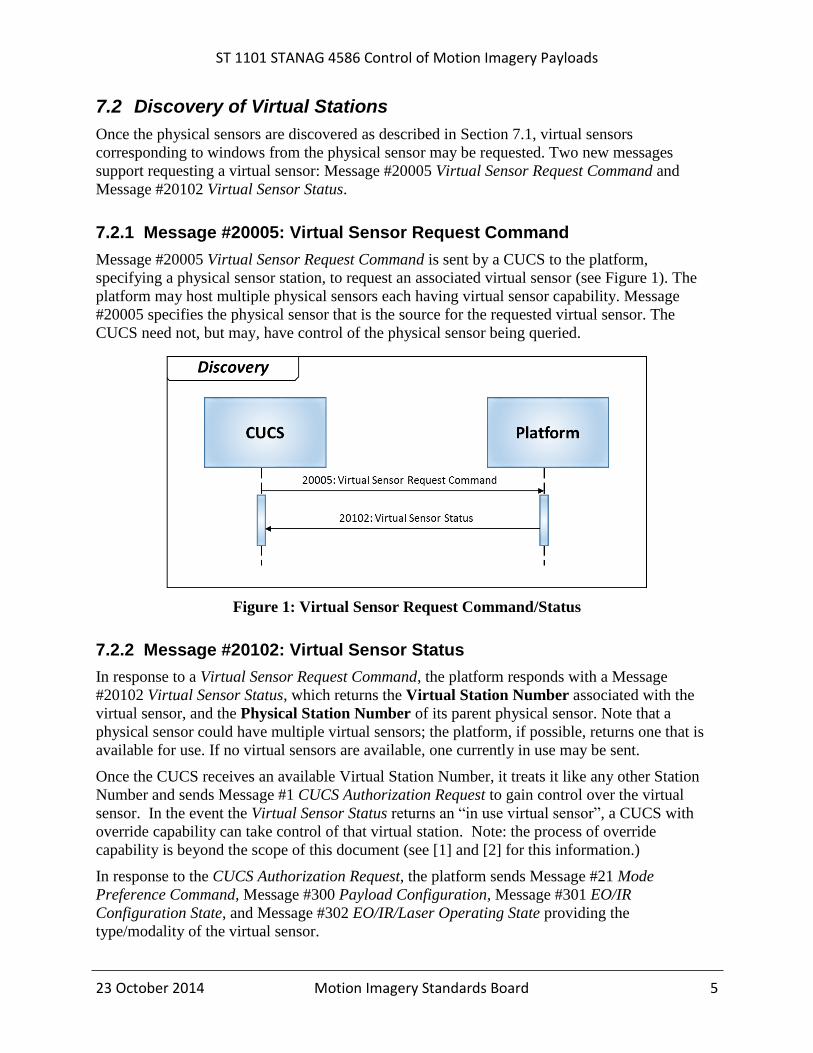
Message #20005 Virtual Sensor Request Command is sent by a CUCS to the platform,
specifying a physical sensor station, to request an associated virtual sensor (see Figure 1). The
platform may host multiple physical sensors each having virtual sensor capability. Message
#20005 specifies the physical sensor that is the source for the requested virtual sensor. The
CUCS need not, but may, have control of the physical sensor being queried.
Figure 1: Virtual Sensor Request Command/Status
7.2.2 Message #20102: Virtual Sensor Status
In response to a Virtual Sensor Request Command, the platform responds with a Message
#20102 Virtual Sensor Status, which returns the Virtual Station Number associated with the
virtual sensor, and the Physical Station Number of its parent physical sensor. Note that a
physical sensor could have multiple virtual sensors; the platform, if possible, returns one that is
available for use. If no virtual sensors are available, one currently in use may be sent.
Once the CUCS receives an available Virtual Station Number, it treats it like any other Station
Number and sends Message #1 CUCS Authorization Request to gain control over the virtual
sensor. In the event the Virtual Sensor Status returns an “in use virtual sensor”, a CUCS with
override capability can take control of that virtual station. Note: the process of override
capability is beyond the scope of this document (see [1] and [2] for this information.)
In response to the CUCS Authorization Request, the platform sends Message #21 Mode
Preference Command, Message #300 Payload Configuration, Message #301 EO/IR
Configuration State, and Message #302 EO/IR/Laser Operating State providing the
type/modality of the virtual sensor.
ST 1101 STANAG 4586 Control of Motion Imagery Payloads
23 October 2014 Motion Imagery Standards Board 6
Requirement(s)
ST 1101-03 A platform that conforms to MISB ST 1101 shall implement Message #20005 Virtual Sensor Request Command and Message #20102 Virtual Sensor Status in accordance with PM ICD [2].
8 Playback from Storage
Playback (moving temporally through Motion Imagery) from an archived data set is an important
but optional capability, since not every platform will provide storage for an archive. Recording
full field-of-view LVMI requires an on-platform archive, because platform-to-ground
communications are likely to be insufficient for delivery. Implementation options for LVMI
retrieval include: 1) provide the capability to transmit real-time live-only windowed Motion
Imagery with no local recording ability (least capable); 2) local buffering or recording of the
most recent M minutes, continually dropping content older than M minutes; and 3) recording all
content locally, while supporting delivery of windowed Motion Imagery (most current LVMI
systems).
The benefits of archive access are compelling. An archive affords “instant replay” of a past
event that may need further review. Data is of higher quality, because it may not be compressed.
Data is persistent and available for future exploitation. LVMI systems enhance these advantages
by allowing the user to re-center on the replayed event if it was originally partially off-screen, to
zoom-in for enhanced detail, or to zoom-out for additional context.
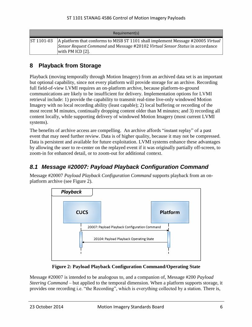
8.1 Message #20007: Payload Playback Configuration Command
Message #20007 Payload Playback Configuration Command supports playback from an on-
platform archive (see Figure 2).
Figure 2: Payload Playback Configuration Command/Operating State
Message #20007 is intended to be analogous to, and a companion of, Message #200 Payload
Steering Command – but applied to the temporal dimension. When a platform supports storage, it
provides one recording i.e. “the Recording”, which is everything collected by a station. There is,
ST 1101 STANAG 4586 Control of Motion Imagery Payloads
23 October 2014 Motion Imagery Standards Board 7
therefore, no need for archive search or selecting from a choice of recordings. Message #20007,
similar to Message #200, is per-station as indicated by the Station Number. Multiple CUCS may
simultaneously adjust the Playback Mode for their own virtual sensor without impacting CUCS
using other virtual sensors.
Requirement(s)
ST 1101-04 In support of a virtual sensor, Message #200 Payload Steering Command and Message #201 EO/IR/Laser Payload Command shall function in accordance with STANAG 4586 [1] when in either the live or archive mode.
ST 1101-05 A Motion Imagery Payload shall support the closest requested Playback Rate.
8.2 Message #20104: Payload Playback Operating State
Message #20104 Payload Playback Operating State reports the operating state of the playback to
the CUCS. It is sent in response to the Payload Playback Configuration Command (Message
#20007) and reflects actual state. If Payload Playback Configuration Command specifies out-of-
capability settings, Payload Playback Operating State indicates the best-effort settings in effect.
Not all systems support all playback options, but are to operate on a best-effort basis. Clearly,
systems without an on-platform archive will not support archive playback. Further limitations are
imposed by the format chosen for the archive and the transcoding capabilities available, for
instance JPEG-2000 to H.264/AVC.
Requirement(s)
ST 1101-06 A platform that conforms to MISB ST 1101 and implements Motion Imagery playback capability shall support Message #20007 Payload Playback Configuration Command and Message #20104 Payload Playback Operating State.
9 Sensor Pointing / Steering
As directing a sensor to point in a particular direction is one of the basic intents of STANAG
4586, this capability is well addressed by Messages #200 and #201 in 4586. Message #201
EO/IR/Laser Payload Command, specifies setup parameters, while Message #200 Payload
Steering Command directs the actual pointing. The meaning of Message #200 is strongly
influenced by the current state of the system, as set with Message #201, particularly the EO/IR
Pointing Mode field of Message #201. For example, if EO/IR Pointing Mode = 4 (Lat-Long
Slaved), then the latitude and longitude fields of Message #200 are populated by the CUCS, and
the sensor responds by pointing toward the specified coordinate. Similarly, if EO/IR Pointing
Mode = 2 (Slewing Rate Relative to AV), then the horizontal and vertical slew rate fields of
Message #200 are populated by the CUCS.
Requirement(s)
ST 1101-07 If Message #201 EO/IR/Laser Payload Command sets EO/IR Pointing Mode = 5 (Target Slaved (track)), then Message #200 Payload Steering Command shall be only used to adjust zoom level (Field 7 Set Zoom) and focus (Field 16 Set Focus); the

ST 1101 STANAG 4586 Control of Motion Imagery Payloads
23 October 2014 Motion Imagery Standards Board 8
latitude, longitude, and slew rate fields will be ignored by the sensor while in target tracking mode.
ST 1101-08 A LVMI system shall support Message #200 and Message #201 (i.e. pan/tilt/zoom) for a non-LVMI aware CUCS.
Sensor pointing using Messages #200 and #201 is intended to function whether a sensor is
physical or virtual. It is likewise intended to work whether a sensor is operating live, or is in
archive playback mode.
10 Motion Imagery Format and Encoder Properties
Message #20000 Encoder Capabilities Request, Message #20100 Encoder Capabilities Status,
Message #20001 Encoder Parameter Control, Message #20103 Encoder Parameter Status,
Message #20006 Encoder Configuration Request and Message # 20002 I-Frame Request (see
Figure 3) all support discovery and selection of the Motion Imagery format, encoding parameters
and transport. It is important the CUCS and the platform agree on which settings to use within
the capabilities available. This is particularly important in supporting backward compatibility.
Figure 3: Motion Imagery Format and Encoding Properties
These six messages enable a platform to be backward compatible with prior generation CUCS’,
and vice versa, without resorting to a sub-optimal least common denominator approach that
doesn’t take full advantage of newer equipment.

ST 1101 STANAG 4586 Control of Motion Imagery Payloads
23 October 2014 Motion Imagery Standards Board 9
10.1 Message #20000: Encoder Capabilities Request
Message #20000 Encoder Capabilities Request is sent by the CUCS to the platform to request
the Motion Imagery encoder capabilities for a specific physical or virtual sensor (Station
Number).
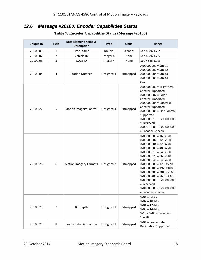
10.2 Message #20100: Encoder Capabilities Status
Message #20100 Encoder Capabilities Status is sent from the platform in response to a Message
#20000 Encoder Capabilities Request. This message indicates the capabilities of the encoder that
can be controlled by the CUCS using Message #20001 Encoder Parameter Control. This is a
variable length message. The Presence of fields 10, 11, and 12 are dependent on the Available
Encoding supported.
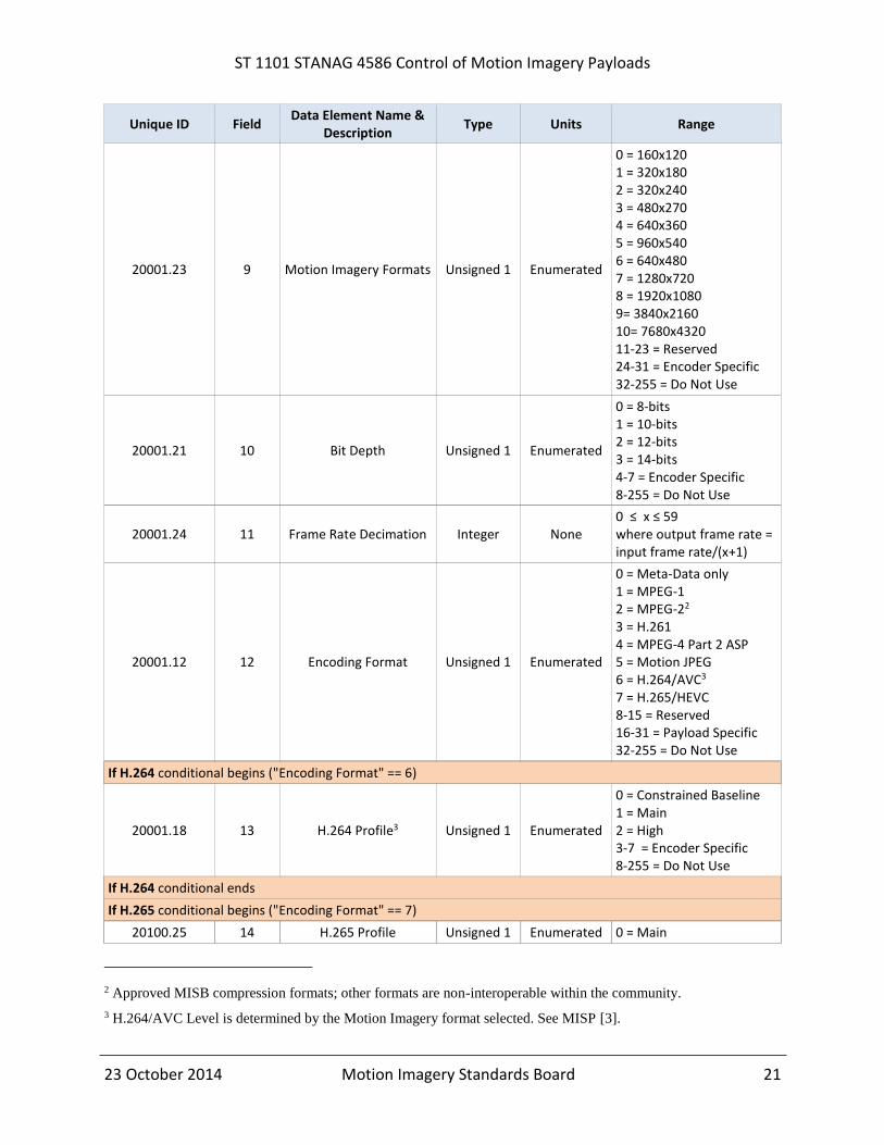
10.3 Message #20001: Encoder Parameter Control
Message #20001 Encoder Parameter Control is sent from the CUCS to the platform to set the
operating parameters of the Motion Imagery encoder for a specific physical or virtual sensor.
Note every field in Message #20001 does not necessarily have a corresponding field in Message
#20100, such as those that vary per available encoding. This is a variable length message. The
Presence of fields 13, 14, and 15 are dependent on the specified Encoding Format.
The Motion Imagery format defines the spatial pixel density (frame size) and temporal frame
rate. A platform’s default values are likely to match the Native format of the sensor for a High
Definition or Enhanced Definition sensor, and constrained by the window format for a LVMI
sensor.
Requirement(s)
ST 1101-09 The Motion Imagery format shall be bounded by the maximum pixel density (frame size) and maximum temporal rate (frame rate) of the sensor.
Over-sampling the Native format of a sensor to deliver more spatial pixels or Frames per Second
inflates the data to transmit and can reduce image quality. The CUCS may assume the encoder is
capable of delivering frame sizes and rates less than specified in Message #20000. If the CUCS
requests a reduced frame size or frame rate, the platform makes a best effort to honor the request.
The platform’s default image format is the format delivered in the absence of instruction to the
contrary, i.e. Message #20001 not sent.
In the Encoder Parameter Control message, the GOP Length is the number of frames from one
I-Frame to the next in an MPEG-compressed signal. Intra-Refresh is a H.264/AVC resiliency
tool for encoding frames on a macro-block by macro-block basis, rather than as a complete
frame; this effectively “spreads” an I-Frame over multiple frames. Intra-Refresh improves both
the utilization of a fixed bandwidth data-link and error resiliency. Reference MISB RP 1011 [6]
for more discussion of Intra-Refresh.

ST 1101 STANAG 4586 Control of Motion Imagery Payloads
23 October 2014 Motion Imagery Standards Board 10
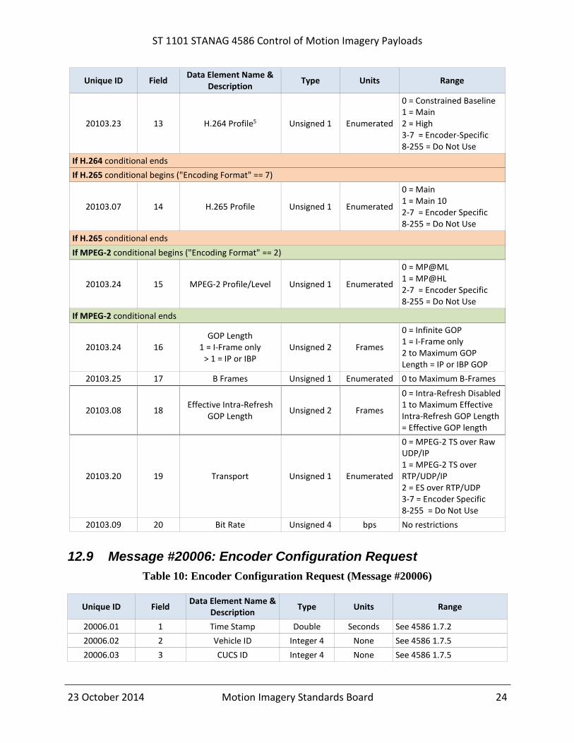
10.4 Message #20103: Encoder Parameter Status
Message #20103 Encoder Parameter Status is sent from the platform to the CUCS in response to
Message #20001 Encoder Parameter Control to indicate the current value of the parameters the
encoder is using. This is a variable length message. The Presence of fields 13, 14, and 15 are
dependent on the specified Encoding format.
Requirement(s)
ST 1101-10 A platform that conforms to MISB ST 1101 shall implement Message #20000 Encoder Capabilities Request, Message #20100 Encoder Capabilities Status, Message #20001 Encoder Parameter Control, and Message #20103 Encoder Parameter Status.
10.5 Message #20006: Encoder Configuration Request
Message #20006 Encoder Configuration Request informs the encoder the CUCS is requesting a
predefined encoder configuration be used. This message allows predefined, pre-stored
configurations to be loaded on command. This is especially useful when capability fields are not
supported in Message #20001 Encoder Parameter Control to invoke the desired operation.
Requirement(s)
ST 1101-11 An encoder shall respond to Message #20006 Encoder Configuration Request with Message #20105 Encoder Configuration Response indicating the current configuration.
It is recommended that any platform or CUCS that supports Motion Imagery support Message
#20006.
Setting the Reset Device field to a value other than zero will cause the device to perform the
specified reset operation. Setting the Configuration Number field to a value other than zero will
cause the device to load the specified stored configuration. Setting both Reset Device and
Configuration Number to zero will allow the software version of the device to be queried without
performing any other operation.
The CUCS may send 4586 Message #1200 Field Configuration Request to discover the available
predefined configurations; values for Fields 6, 7 and 8 are shown in Table 1. The CUCS uses this
message to update DLI (Data Link Interface) parameter configuration data at the CUCS, and to
potentially control the display of information.
Requirement(s)
ST 1101-12 When a CUCS sends Message #1200 Field Configuration Request, the VSM shall respond with one or more Message #1302 Field Configuration Enumerated Response message(s) with configurations supported by the VSM.
ST 1101-13 A CUCS shall populate Message #1200 Field Configuration Request as indicated in MISB ST 1101 Table 1.

ST 1101 STANAG 4586 Control of Motion Imagery Payloads
23 October 2014 Motion Imagery Standards Board 11
Table 1: 4586 Message #1200 Field Configuration Request Values
Unique ID Field Data Element Name &
Description Type Value Note
1200.06 6 Request Type Unsigned 1 0 0 = Single Parameter
1200.07 7 Request Message Unsigned 4 20006 The final message number for Load Predefined Configuration Request
1200.08 8 Request Field Unsigned 1 6 The field number for the Configuration Number
The VSM responds with a Message #1302 Field Configuration Enumerated Response for each
pre-defined configuration available.
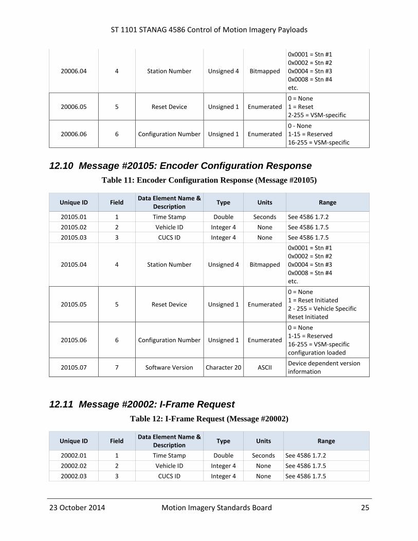
10.6 Message #20105: Encoder Configuration Response
Message #20105 Encoder Configuration Response informs the client the encoder has performed
the requested operation. In addition, this message returns the software version of the device.
It is recommended that any platform or CUCS that supports motion imagery support Message
#20105.
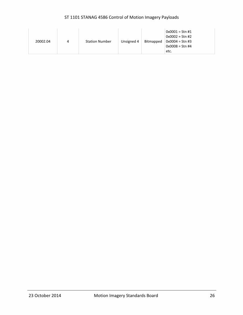
10.7 Message #20002: I-Frame Request
Message #20002 I-Frame Request Message informs the encoder that the CUCS has suffered data
loss and is requesting an I-Frame be sent to resynchronize. Message #20002 has no parameters
other than those present in all payload messages. The encoder may honor Message #20002 at its
own discretion. For example, if Intra-Refresh mode is enabled, the encoder might respond to
Message #20002 by increasing the number of I-macro-blocks sent per frame over some period of
time rather than sending an actual I-Frame.
It is recommended that any platform or CUCS that supports Motion Imagery support Message
#20002.
11 Metadata Selection and Filtering
The MISP defines Metadata to support various capabilities. Some Metadata consumes significant
bandwidth. This additional data needs to be accounted in determining the overall data rate versus
transmission channel capacity. Reference MISB ST 0902 [4] for minimum metadata
requirements.
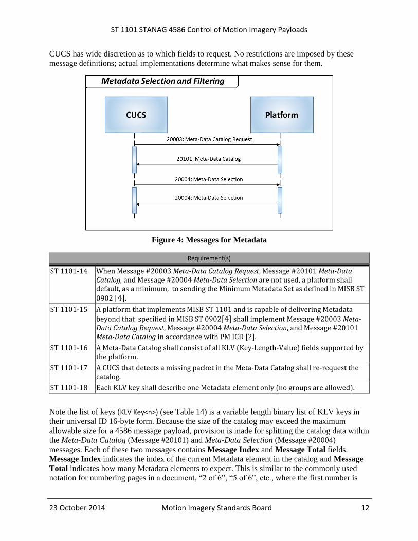
Three messages support Motion Imagery Metadata (see Figure 4). The CUCS first sends
Message #20003 Meta-Data Catalog Request and, in turn, receives a Message #20101 Meta-
Data Catalog response. The CUCS selects a subset of Metadata from the returned catalog and
replies with Message #20004 Meta-Data Selection. For the remaining session, the Motion
Imagery (or Metadata only) stream contains just those requested elements – unless changed. A
ST 1101 STANAG 4586 Control of Motion Imagery Payloads
23 October 2014 Motion Imagery Standards Board 12
CUCS has wide discretion as to which fields to request. No restrictions are imposed by these
message definitions; actual implementations determine what makes sense for them.
Figure 4: Messages for Metadata
Requirement(s)
ST 1101-14 When Message #20003 Meta-Data Catalog Request, Message #20101 Meta-Data Catalog, and Message #20004 Meta-Data Selection are not used, a platform shall default, as a minimum, to sending the Minimum Metadata Set as defined in MISB ST
0902 [4].
ST 1101-15 A platform that implements MISB ST 1101 and is capable of delivering Metadata
beyond that specified in MISB ST 0902[4] shall implement Message #20003 Meta-Data Catalog Request, Message #20004 Meta-Data Selection, and Message #20101 Meta-Data Catalog in accordance with PM ICD [2].
ST 1101-16 A Meta-Data Catalog shall consist of all KLV (Key-Length-Value) fields supported by the platform.
ST 1101-17 A CUCS that detects a missing packet in the Meta-Data Catalog shall re-request the catalog.
ST 1101-18 Each KLV key shall describe one Metadata element only (no groups are allowed).
Note the list of keys (KLV Key<n>) (see Table 14) is a variable length binary list of KLV keys in
their universal ID 16-byte form. Because the size of the catalog may exceed the maximum
allowable size for a 4586 message payload, provision is made for splitting the catalog data within
the Meta-Data Catalog (Message #20101) and Meta-Data Selection (Message #20004)
messages. Each of these two messages contains Message Index and Message Total fields.
Message Index indicates the index of the current Metadata element in the catalog and Message
Total indicates how many Metadata elements to expect. This is similar to the commonly used
notation for numbering pages in a document, “2 of 6”, “5 of 6”, etc., where the first number is

ST 1101 STANAG 4586 Control of Motion Imagery Payloads
23 October 2014 Motion Imagery Standards Board 13
the current page and the second is the total number of pages. Key Count is constrained to 30 for
Message #20101 and 24 for Message #20004 to ensure the message payload size limit is not
exceeded.
11.1 Message #20004: Meta-Data Selection
Message #20004 Meta-Data Selection includes a transmit rate Key Rate (in seconds) for each
key. In other words, the Metadata element indicated by the key is sent by the platform to the
CUCS at a specified rate. The rate specification allows a CUCS to request a lower than actual
rate for reducing the bandwidth. A transmit rate of Key Rate =0.0 turns off the transmission of a
key.
Requirement(s)
ST 1101-19 A platform that detects a missing field in a requested Meta-Data Selection shall ignore the selection request, and send Message #20004 Meta-Data Selection back to the CUCS with Field 7 Key Count = 0 to signal a problem.
ST 1101-20 When a CUCS receives a Message #20004 Meta-Data Selection that indicates Field 7 Key Count = 0, it shall respond by resending the selection.
ST 1101-21 When a platform is unable to provide the metadata element at the rate the CUCS requests, the platform shall respond with Message #20004 Meta-Data Selection containing the actual rate it can support.
ST 1101-22 A platform shall not interpolate metadata to achieve a higher rate than the actual Metadata rate, which is to be treated as the upper bound for rate.
ST 1101 STANAG 4586 Control of Motion Imagery Payloads
23 October 2014 Motion Imagery Standards Board 14
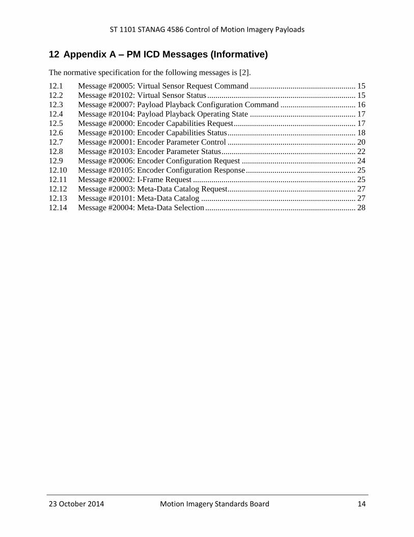
12 Appendix A – PM ICD Messages (Informative)
The normative specification for the following messages is [2].
12.1 Message #20005: Virtual Sensor Request Command .................................................... 15 12.2 Message #20102: Virtual Sensor Status ......................................................................... 15 12.3 Message #20007: Payload Playback Configuration Command ..................................... 16 12.4 Message #20104: Payload Playback Operating State .................................................... 17
12.5 Message #20000: Encoder Capabilities Request ............................................................ 17 12.6 Message #20100: Encoder Capabilities Status ............................................................... 18 12.7 Message #20001: Encoder Parameter Control ............................................................... 20 12.8 Message #20103: Encoder Parameter Status .................................................................. 22 12.9 Message #20006: Encoder Configuration Request ........................................................ 24
12.10 Message #20105: Encoder Configuration Response ...................................................... 25
12.11 Message #20002: I-Frame Request ................................................................................ 25
12.12 Message #20003: Meta-Data Catalog Request ............................................................... 27 12.13 Message #20101: Meta-Data Catalog ............................................................................ 27
12.14 Message #20004: Meta-Data Selection .......................................................................... 28
ST 1101 STANAG 4586 Control of Motion Imagery Payloads
23 October 2014 Motion Imagery Standards Board 15
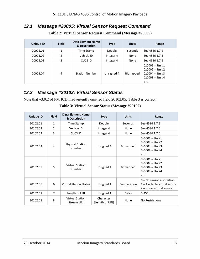
12.1 Message #20005: Virtual Sensor Request Command
Table 2: Virtual Sensor Request Command (Message #20005)
Unique ID Field Data Element Name
& Description Type Units Range
20005.01 1 Time Stamp Double Seconds See 4586 1.7.2
20005.02 2 Vehicle ID Integer 4 None See 4586 1.7.5
20005.03 3 CUCS ID Integer 4 None See 4586 1.7.5
20005.04 4 Station Number Unsigned 4 Bitmapped
0x0001 = Stn #1 0x0002 = Stn #2 0x0004 = Stn #3 0x0008 = Stn #4 etc.
12.2 Message #20102: Virtual Sensor Status
Note that v3.0.2 of PM ICD inadvertently omitted field 20102.05. Table 3 is correct.
Table 3: Virtual Sensor Status (Message #20102)
Unique ID Field Data Element Name
& Description Type Units Range
20102.01 1 Time Stamp Double Seconds See 4586 1.7.2
20102.02 2 Vehicle ID Integer 4 None See 4586 1.7.5
20102.03 3 CUCS ID Integer 4 None See 4586 1.7.5
20102.04 4 Physical Station
Number Unsigned 4 Bitmapped
0x0001 = Stn #1 0x0002 = Stn #2 0x0004 = Stn #3 0x0008 = Stn #4 etc.
20102.05 5 Virtual Station
Number Unsigned 4 Bitmapped
0x0001 = Stn #1 0x0002 = Stn #2 0x0004 = Stn #3 0x0008 = Stn #4 etc.
20102.06 6 Virtual Station Status Unsigned 1 Enumeration 0 = No sensor association 1 = Available virtual sensor 2 = In use virtual sensor
20102.07 7 Length of URI Unsigned 1 Bytes 5-255
20102.08 8 Virtual Station
Stream URI Character
[Length of URI] None No Restrictions

ST 1101 STANAG 4586 Control of Motion Imagery Payloads
23 October 2014 Motion Imagery Standards Board 16
12.3 Message #20007: Payload Playback Configuration Command
Table 4: Payload Playback Configuration Command (Message #20007)
Unique ID Field Data Element Name &
Description Type Units Range
20007.01 1 Time Stamp Double Seconds See 4586 1.7.2
20007.02 2 Vehicle ID Integer 4 None See 4586 1.7.5
20007.03 3 CUCS ID Integer 4 None See 4586 1.7.5
20007.04 4 Station Number Unsigned 4 Bitmapped
0x0001 = Stn #1 0x0002 = Stn #2 0x0004 = Stn #3 0x0008 = Stn #4 etc.
20007.05 5 Playback Mode Unsigned 1 Enumerated
0 = Live 1 = from archive 2 = calibration image 3-128 = Reserved 129-255 = payload specific
20007.06 6 Playback Rate Float Fraction 0.0 <= x
20007.07 7 Seek Location
(absolute time) Double Seconds See 4586 1.7.2
Playback Mode specifies whether the given Station Number delivers a stream from a live (0)
sensor, or is derived from archived (1) data. There is also an option to provide a calibration
image (2), which is highly recommended. Values 3-128 are reserved to support future
capabilities.
Playback Rate specifies the playback speed of the archived data as a fraction of the real-time
rate. For example, a Playback Rate = 1.0 designates real-time playback; 0.0 designates paused;
2.0 designates a 2x real-time fast forward; and 0.5 designates half speed slow-motion.
Seek Location indicates a point in time to begin play with the value 0.0 denoting no change to
the playback location (only rate is being changed). This field is ignored for Playback Mode 0 =
Live.
Panning and zooming within an image may be accomplished by setting the Playback Rate = 0.0
(paused) at any point in time, and utilizing Message #200 Payload Steering Command. While the
returned data is a Motion Imagery stream, to the user the effect is roaming over a large image
space.

ST 1101 STANAG 4586 Control of Motion Imagery Payloads
23 October 2014 Motion Imagery Standards Board 17
12.4 Message #20104: Payload Playback Operating State
Table 5: Payload Playback Operating State (Message #20104)
Unique ID Field Data Element Name &
Description Type Units Range
20104.01 1 Time Stamp Double Seconds See 4586 1.7.2
20104.02 2 Vehicle ID Integer 4 None See 4586 1.7.5
20104.03 3 CUCS ID Integer 4 None See 4586 1.7.5
20104.04 4 Station Number Unsigned 4 Bitmapped
0x0001 = Stn #1 0x0002 = Stn #2 0x0004 = Stn #3 0x0008 = Stn #4 etc.
20104.05 5 Playback Mode Unsigned 1 Enumerated
0 = Live 1 = from archive 3 = calibration image 3-128 = Reserved 129-255 = payload specific
20104.06 6 Playback Rate Float Fraction 0.0 <= x
20104.07 7 Seek Location (absolute
time) Double Seconds See 4586 1.7.2
12.5 Message #20000: Encoder Capabilities Request
Table 6: Encoder Capabilities Request (Message #20000)
Unique ID Field Data Element Name &
Description Type Units Range
20000.01 1 Time Stamp Double Seconds See 4586 1.7.2
20000.02 2 Vehicle ID Integer 4 None See 4586 1.7.5
20000.03 3 CUCS ID Integer 4 None See 4586 1.7.5
20000.04 4 Station Number Unsigned 4 Bitmapped
0x0001 = Stn #1 0x0002 = Stn #2 0x0004 = Stn #3 0x0008 = Stn #4 etc.
ST 1101 STANAG 4586 Control of Motion Imagery Payloads
23 October 2014 Motion Imagery Standards Board 18
12.6 Message #20100: Encoder Capabilities Status
Table 7: Encoder Capabilities Status (Message #20100)
Unique ID Field Data Element Name &
Description Type Units Range
20100.01 1 Time Stamp Double Seconds See 4586 1.7.2
20100.02 2 Vehicle ID Integer 4 None See 4586 1.7.5
20100.03 3 CUCS ID Integer 4 None See 4586 1.7.5
20100.04 4 Station Number Unsigned 4 Bitmapped
0x00000001 = Stn #1 0x00000002 = Stn #2 0x00000004 = Stn #3 0x00000008 = Stn #4 etc.
20100.27 5 Motion Imagery Control Unsigned 4 Bitmapped
0x00000001 = Brightness Control Supported 0x00000002 = Color Control Supported 0x00000004 = Contrast Control Supported 0x00000008 = Tint Control Supported 0x00000010 - 0x00008000 = Reserved 0x00010000 - 0x80000000 = Encoder-Specific
20100.28 6 Motion Imagery Formats Unsigned 2 Bitmapped
0x00000001 = 160x120 0x00000002 = 320x180 0x00000004 = 320x240 0x00000008 = 480x270 0x00000010 = 640x360 0x00000020 = 960x540 0x00000040 = 640x480 0x00000080 = 1280x720 0x00000100 = 1920x1080 0x00000200 = 3840x2160 0x00000400 = 7680x4320 0x00000800 - 0x00800000 = Reserved 0x01000000 - 0x80000000 = Encoder-Specific
20100.25 7 Bit Depth Unsigned 1 Bitmapped
0x01 = 8-bits 0x02 = 10-bits 0x04 = 12-bits 0x08 = 14-bits 0x10 - 0x80 = Encoder-Specific
20100.29 8 Frame Rate Decimation Unsigned 1 Bitmapped 0x01 = Frame Rate Decimation Supported

ST 1101 STANAG 4586 Control of Motion Imagery Payloads
23 October 2014 Motion Imagery Standards Board 19
Unique ID Field Data Element Name &
Description Type Units Range
0x02 - 0x80 = Encoder-Specific
20100.08 9 Available Encodings Unsigned 4 Bitmapped
0x00000001 = Meta-Data Only 0x00000002 = MPEG-1 0x00000004 = MPEG-2 0x00000008 = H.261 0x00000010 = MPEG-4 Part 2 ASP 0x00000020 = Motion JPEG 0x00000040 = H.264/MPEG-4 Part 10 0x00000080 = H.265/HEVC 0x00000100 - 0x00008000 = Reserved 0x00010000 - 0x80000000 = Vehicle-Specific
If H.264 conditional begins (“Available Encodings” bit 6 == 1)
20100.22 10 H.264 Profile1 Unsigned 1 Bitmapped
0x01 = Constrained Baseline 0x02 = Main 0x04 = High 0x08 - 0x80 = Encoder- Specific
If H.264 conditional ends
If H.265 conditional begins (“Available Encodings” bit 7 == 1)
20100.36 11 H.265 Profile Unsigned 1 Bitmapped
0x01 = Main 0x02 = Main 10 0x04 - 0x80 = Encoder-Specific
If H.265 conditional ends
If MPEG-2 conditional begins (“Available Encodings” bit 2 == 1)
20100.23 12 MPEG-2 Profile/Level Unsigned 1 Bitmapped
0x01 = MP@ML 0x02 = MP@HL 0x04 - 0x80 = Encoder- Specific
If MPEG-2 conditional ends
20100.31 13 Maximum GOP Length Unsigned 2 Frames 1 ≤ x
20100.32 14 Maximum B Frames Unsigned 1 Frames X ≤ 4
20100.22 15 Infinite GOP / Intra-
Refresh Unsigned 1 Bitmapped
0x01 = Infinite GOP Supported 0x02 = Intra-Refresh Supported
1 H.264/AVC Level is determined by the Motion Imagery format selected. See MISP [3].

ST 1101 STANAG 4586 Control of Motion Imagery Payloads
23 October 2014 Motion Imagery Standards Board 20
Unique ID Field Data Element Name &
Description Type Units Range
0x04 - 0x80 = Encoder- Specific
20100.24 16 Maximum Effective Intra-Refresh GOP
Length Unsigned 2 Frames 1 ≤ x
20100.18 17 Transport Unsigned 1 Bitmapped
0x01 = MPEG-2 TS over Raw UDP/IP 0x02 = MPEG-2 TS over RTP/UDP/IP 0x04 = ES over RTP/UDP/IP 0x08 - 0x80 = Encoder-Specific
20100.19 18 Max Bit Rate Unsigned 4 bps No restrictions
20100.35 19 Predefined Encoder
Configurations Unsigned 1 None
X = 0 (Predefined Configurations not supported) 1 ≤ x (Number of available Predefined Configurations)
12.7 Message #20001: Encoder Parameter Control
Table 8: Encoder Parameter Control (Message #20001)
Unique ID Field Data Element Name &
Description Type Units Range
20001.01 1 Time Stamp Double Seconds See 4586 1.7.2
20001.02 2 Vehicle ID Integer 4 None See 4586 1.7.5
20001.03 3 CUCS ID Integer 4 None See 4586 1.7.5
20001.04 4 Station Number Unsigned 4 Bitmapped
0x0001 = Stn #1 0x0002 = Stn #2 0x0004 = Stn #3 0x0008 = Stn #4 etc.
20001.05 5 Brightness Unsigned 1 None
0x00 = minimum brightness 0xFF = maximum brightness
20001.06 6 Color Unsigned 1 None
0x00 = minimum saturation 0xFF = maximum saturation
20001.07 7 Contrast Unsigned 1 None 0x00 = minimum contrast 0xFF = maximum contrast
20001.08 8 Tint Unsigned 1 None 0x00 = maximize green 0x80 = normal color 0xFF = maximum magenta
ST 1101 STANAG 4586 Control of Motion Imagery Payloads
23 October 2014 Motion Imagery Standards Board 21
Unique ID Field Data Element Name &
Description Type Units Range
20001.23 9 Motion Imagery Formats Unsigned 1 Enumerated
0 = 160x120 1 = 320x180 2 = 320x240 3 = 480x270 4 = 640x360 5 = 960x540 6 = 640x480 7 = 1280x720 8 = 1920x1080 9= 3840x2160 10= 7680x4320 11-23 = Reserved 24-31 = Encoder Specific 32-255 = Do Not Use
20001.21 10 Bit Depth Unsigned 1 Enumerated
0 = 8-bits 1 = 10-bits 2 = 12-bits 3 = 14-bits 4-7 = Encoder Specific 8-255 = Do Not Use
20001.24 11 Frame Rate Decimation Integer None 0 ≤ x ≤ 59 where output frame rate = input frame rate/(x+1)
20001.12 12 Encoding Format Unsigned 1 Enumerated
0 = Meta-Data only 1 = MPEG-1 2 = MPEG-22 3 = H.261 4 = MPEG-4 Part 2 ASP 5 = Motion JPEG 6 = H.264/AVC3 7 = H.265/HEVC 8-15 = Reserved 16-31 = Payload Specific 32-255 = Do Not Use
If H.264 conditional begins ("Encoding Format" == 6)
20001.18 13 H.264 Profile3 Unsigned 1 Enumerated
0 = Constrained Baseline 1 = Main 2 = High 3-7 = Encoder Specific 8-255 = Do Not Use
If H.264 conditional ends
If H.265 conditional begins ("Encoding Format" == 7)
20100.25 14 H.265 Profile Unsigned 1 Enumerated 0 = Main
2 Approved MISB compression formats; other formats are non-interoperable within the community.
3 H.264/AVC Level is determined by the Motion Imagery format selected. See MISP [3].

ST 1101 STANAG 4586 Control of Motion Imagery Payloads
23 October 2014 Motion Imagery Standards Board 22
Unique ID Field Data Element Name &
Description Type Units Range
1 = Main 10 2-7 = Encoder Specific 8-255 = Do Not Use
If H.265 conditional ends
If MPEG-2 conditional begins ("Encoding Format" == 2)
20001.19 15 MPEG-2 Profile/Level Unsigned 1 Enumerated
0 = MP@ML 1 = MP@HL 2-7 = Encoder-Specific 8-255 = Do Not Use
If MPEG-2 conditional ends
20001.16 17
GOP Length 1 = I-Frame only
> 1 = IP (set Field 18 B Frames = 0) or IBP
Unsigned 2 Frames
0 = Infinite GOP 1 = I-Frame only 2 to Maximum GOP Length = IP or IBP GOP
20001.17 18 B Frames Unsigned 1 Enumerated 0 to Maximum B-Frames
20001.26 19 Effective Intra-Refresh
GOP Length Unsigned 2 Frames
0 = Intra-Refresh Disabled 1 to Maximum Effective Intra-Refresh GOP Length = Effective GOP length
20001.14 20 Transport Unsigned 1 Enumerated
0 = MPEG-2 TS over Raw UDP 1 = MPEG-2 TS over RTP/UDP 2 = ES over RTP/UDP 3-7 = Encoder Specific 8-255 = Do Not Use
20001.15 21 Bit Rate Unsigned 4 bps No restrictions
12.8 Message #20103: Encoder Parameter Status
Table 9: Encoder Parameter Status (Message #20103)
Unique ID Field Data Element Name &
Description Type Units Range
20103.01 1 Time Stamp Double Seconds See 4586 1.7.2
20103.02 2 Vehicle ID Integer 4 None See 4586 1.7.5
20103.03 3 CUCS ID Integer 4 None See 4586 1.7.5
20103.04 4 Station Number Unsigned 4 Bitmapped
0x0001 = Stn #1 0x0002 = Stn #2 0x0004 = Stn #3 0x0008 = Stn #4 etc.
20103.09 5 Brightness Unsigned 1 None
0x00 = minimum brightness 0xFF = maximum brightness

ST 1101 STANAG 4586 Control of Motion Imagery Payloads
23 October 2014 Motion Imagery Standards Board 23
Unique ID Field Data Element Name &
Description Type Units Range
20103.10 6 Color Unsigned 1 None
0x00 = minimum saturation 0xFF = maximum saturation
20103.11 7 Contrast Unsigned 1 None 0x00 = minimum contrast 0xFF = maximum contrast
20103.12 8 Tint Unsigned 1 None 0x00 = maximize green 0x80 = normal color 0xFF = maximum magenta
20103.05 9 Motion Imagery Formats Unsigned 1 Enumerated
0 = 160x120 1 = 320x180 2 = 320x240 3 = 480x270 4 = 640x360 5 = 960x540 6 = 640x480 7 = 1280x720 8 = 1920x1080 9= 3840x2160 10= 7680x4320 11-23 = Reserved 24-31 = Encoder Specific 32-255 = Do Not Use
20103.25 10 Bit Depth Unsigned 1 Enumerated
0 = 8-bits 1 = 10-bits 2 = 12-bits 3 = 14-bits 4-7 = Encoder Specific 8-255 = Do Not Use
20103.06 11 Frame Rate Decimation Integer None 0 ≤ x ≤ 59 where output frame rate = input frame rate/(x+1)
20103.17 12 Encoding Format Unsigned 1 Enumerated
0 = Meta-Data only 1 = MPEG-1 2 = MPEG-24 3 = H.261 4 = MPEG-4 Part 2 ASP 5 = Motion JPEG 6 = H.264/AVC5 7 = H.265/HEVC 8-15 = Reserved 16-31 = Payload-Specific 32-255 = Do Not Use
If H.264 conditional begins ("Encoding Format" == 6)
4 Approved MISB compression formats; other formats are non-interoperable within the community.
5 H.264/AVC Level is determined by the Motion Imagery format selected. See MISP [3].
ST 1101 STANAG 4586 Control of Motion Imagery Payloads
23 October 2014 Motion Imagery Standards Board 24
Unique ID Field Data Element Name &
Description Type Units Range
20103.23 13 H.264 Profile5 Unsigned 1 Enumerated
0 = Constrained Baseline 1 = Main 2 = High 3-7 = Encoder-Specific 8-255 = Do Not Use
If H.264 conditional ends
If H.265 conditional begins ("Encoding Format" == 7)
20103.07 14 H.265 Profile Unsigned 1 Enumerated
0 = Main 1 = Main 10 2-7 = Encoder Specific 8-255 = Do Not Use
If H.265 conditional ends
If MPEG-2 conditional begins ("Encoding Format" == 2)
20103.24 15 MPEG-2 Profile/Level Unsigned 1 Enumerated
0 = MP@ML 1 = MP@HL 2-7 = Encoder Specific 8-255 = Do Not Use
If MPEG-2 conditional ends
20103.24 16 GOP Length
1 = I-Frame only > 1 = IP or IBP
Unsigned 2 Frames
0 = Infinite GOP 1 = I-Frame only 2 to Maximum GOP Length = IP or IBP GOP
20103.25 17 B Frames Unsigned 1 Enumerated 0 to Maximum B-Frames
20103.08 18 Effective Intra-Refresh
GOP Length Unsigned 2 Frames
0 = Intra-Refresh Disabled 1 to Maximum Effective Intra-Refresh GOP Length = Effective GOP length
20103.20 19 Transport Unsigned 1 Enumerated
0 = MPEG-2 TS over Raw UDP/IP 1 = MPEG-2 TS over RTP/UDP/IP 2 = ES over RTP/UDP 3-7 = Encoder Specific 8-255 = Do Not Use
20103.09 20 Bit Rate Unsigned 4 bps No restrictions
12.9 Message #20006: Encoder Configuration Request
Table 10: Encoder Configuration Request (Message #20006)
Unique ID Field Data Element Name &
Description Type Units Range
20006.01 1 Time Stamp Double Seconds See 4586 1.7.2
20006.02 2 Vehicle ID Integer 4 None See 4586 1.7.5
20006.03 3 CUCS ID Integer 4 None See 4586 1.7.5
ST 1101 STANAG 4586 Control of Motion Imagery Payloads
23 October 2014 Motion Imagery Standards Board 25
20006.04 4 Station Number Unsigned 4 Bitmapped
0x0001 = Stn #1 0x0002 = Stn #2 0x0004 = Stn #3 0x0008 = Stn #4 etc.
20006.05 5 Reset Device Unsigned 1 Enumerated 0 = None 1 = Reset 2-255 = VSM-specific
20006.06 6 Configuration Number Unsigned 1 Enumerated 0 - None 1-15 = Reserved 16-255 = VSM-specific
12.10 Message #20105: Encoder Configuration Response
Table 11: Encoder Configuration Response (Message #20105)
Unique ID Field Data Element Name &
Description Type Units Range
20105.01 1 Time Stamp Double Seconds See 4586 1.7.2
20105.02 2 Vehicle ID Integer 4 None See 4586 1.7.5
20105.03 3 CUCS ID Integer 4 None See 4586 1.7.5
20105.04 4 Station Number Unsigned 4 Bitmapped
0x0001 = Stn #1 0x0002 = Stn #2 0x0004 = Stn #3 0x0008 = Stn #4 etc.
20105.05 5 Reset Device Unsigned 1 Enumerated
0 = None 1 = Reset Initiated 2 - 255 = Vehicle Specific Reset Initiated
20105.06 6 Configuration Number Unsigned 1 Enumerated
0 = None 1-15 = Reserved 16-255 = VSM-specific configuration loaded
20105.07 7 Software Version Character 20 ASCII Device dependent version information
12.11 Message #20002: I-Frame Request
Table 12: I-Frame Request (Message #20002)
Unique ID Field Data Element Name &
Description Type Units Range
20002.01 1 Time Stamp Double Seconds See 4586 1.7.2
20002.02 2 Vehicle ID Integer 4 None See 4586 1.7.5
20002.03 3 CUCS ID Integer 4 None See 4586 1.7.5
ST 1101 STANAG 4586 Control of Motion Imagery Payloads
23 October 2014 Motion Imagery Standards Board 26
20002.04 4 Station Number Unsigned 4 Bitmapped
0x0001 = Stn #1 0x0002 = Stn #2 0x0004 = Stn #3 0x0008 = Stn #4 etc.

ST 1101 STANAG 4586 Control of Motion Imagery Payloads
23 October 2014 Motion Imagery Standards Board 27
12.12 Message #20003: Meta-Data Catalog Request
Table 13: Meta-Data Catalog Request (Message #20003)
Unique ID Field Data Element Name &
Description Type Units Range
20003.01 1 Time Stamp Double Seconds See 4586 1.7.2
20003.02 2 Vehicle ID Integer 4 None See 4586 1.7.5
20003.03 3 CUCS ID Integer 4 None See 4586 1.7.5
20003.04 4 Station Number Unsigned 4 Bitmapped
0x0001 = Stn #1 0x0002 = Stn #2 0x0004 = Stn #3 0x0008 = Stn #4 etc.
12.13 Message #20101: Meta-Data Catalog
Table 14: Meta-Data Catalog (Message #20101)
Unique ID Field Data Element
Name & Description
Type Units Range
20101.01 1 Time Stamp Double Seconds See 4586 1.7.2
20101.02 2 Vehicle ID Integer 4 None See 4586 1.7.5
20101.03 3 CUCS ID Integer 4 None See 4586 1.7.5
20101.04 4 Station Number Unsigned 4 Bitmapped
0x0001 = Stn #1 0x0002 = Stn #2 0x0004 = Stn #3 0x0008 = Stn #4 etc.
20101.05 5 Message Index Unsigned 2 Number 1 <= X <= Message Total
20101.06 6 Message Total Unsigned 2 Number No restrictions
20101.07 7 Key Count Unsigned 1 Number 0 <= X <= 30
Keys repetition begins (where n = 1 to 30)
20101.08 8 KLV Key<n> Binary 16 KLV Key, 16 bytes
Valid MISP KLV keys

ST 1101 STANAG 4586 Control of Motion Imagery Payloads
23 October 2014 Motion Imagery Standards Board 28
12.14 Message #20004: Meta-Data Selection
Table 15: Meta-Data Selection (Message #20004)
Unique ID Field Data Element
Name & Description
Type Units Range
20004.01 1 Time Stamp Double Seconds See 4586 1.7.2
20004.02 2 Vehicle ID Integer 4 None See 4586 1.7.5
20004.03 3 CUCS ID Integer 4 None See 4586 1.7.5
20004.04 4 Station Number Unsigned 4 Bitmapped
0x0001 = Stn #1 0x0002 = Stn #2 0x0004 = Stn #3 0x0008 = Stn #4 etc.
20004.05 5 Message Index Unsigned 2 Number 1 <= X <= Message Total
20004.06 6 Message Total Unsigned 2 Number No restrictions
20004.07 7 Key Count Unsigned 1 Number 0 <= X <= 24
Key/Rate repetition begins (where n = 1 to 24)
20004.08 See Note 6 KLV Key<n> Binary 16 KLV Key, 16 bytes
Valid MISP KLV key
20004.09 See Note 7 Key Rate
(0.0 = stop sending)
Float Seconds >= 0.0
6 Field is a loop for n keys beginning with Field 08.
7 Field is a loop for n keys beginning with Field 09.

ST 1101 STANAG 4586 Control of Motion Imagery Payloads
23 October 2014 Motion Imagery Standards Board 29
13 Appendix B – Proposed Messages (Informative)
The messages described here have not yet been accepted into the PM ICD. They are for future
consideration only.
13.1 Image Coordinate System
LVMI sensors raise the question of image coordinate system. While the imagery delivered from
traditional High and Enhanced Definition sensors is generally assumed to be in raw camera/pixel
space, with LVMI sensors it is common to deliver the imagery in a geographic coordinate
system. For this reason, Message #M1 Set Coordinate System is added (Table 16). This message
is a setup message analogous to Message #201, and impacts the meaning of Message #200.
Beyond the standard fields that all messages have, Message #M1 has a single enumerated field
with four coordinate systems currently as defined in Table 17.
Table 16: Set Coordinate System (Message #M1)
Unique ID Field Data Element Name &
Description Type Units Range
0XYZ.01 1 Time Stamp Double Seconds See 4586 1.7.2
0XYZ.02 2 Vehicle ID Integer 4 None See 4586 1.7.5
0XYZ.03 3 CUCS ID Integer 4 None See 4586 1.7.5
0XYZ.04 4 Station Number Unsigned 4 Bitmapped
0x0001 = Stn #1 0x0002 = Stn #2 0x0004 = Stn #3 0x0008 = Stn #4 etc.
0XYZ.05 5 Coordinate System Unsigned 1 Enumerated See Table 17
Table 17: Image Coordinate System Enumeration
Mode Image Coordinate System Interpretation of Message #200
0 Default Camera / Pixel Space Unchanged
1 Geo-registered north-is-up 0200.07 – 0200.10 change units to Meters or Meters/sec rather than Radians or Radians/ sec
2 Geo-registered up-is-up 0200.07 – 0200.10 change units to Meters or Meters /sec rather than Radians or Radians/sec
3 Relative Camera Space up-is-up 0200.07 – 0200.10 change units to fraction of FOV (0.0 to 1.0) or fraction of FOV/sec rather than Radians or Radians /sec
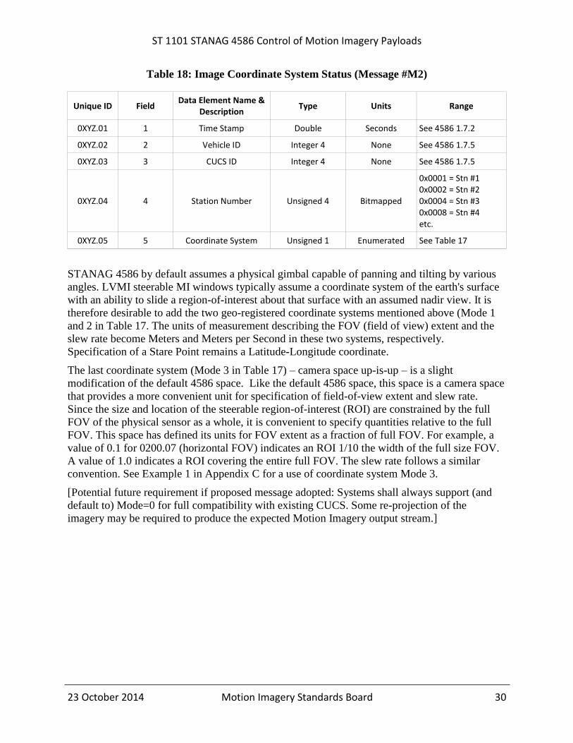
Message #M2 Image Coordinate System Status retrieves the current coordinate system in use on
the platform.
ST 1101 STANAG 4586 Control of Motion Imagery Payloads
23 October 2014 Motion Imagery Standards Board 30
Table 18: Image Coordinate System Status (Message #M2)
Unique ID Field Data Element Name &
Description Type Units Range
0XYZ.01 1 Time Stamp Double Seconds See 4586 1.7.2
0XYZ.02 2 Vehicle ID Integer 4 None See 4586 1.7.5
0XYZ.03 3 CUCS ID Integer 4 None See 4586 1.7.5
0XYZ.04 4 Station Number Unsigned 4 Bitmapped
0x0001 = Stn #1 0x0002 = Stn #2 0x0004 = Stn #3 0x0008 = Stn #4 etc.
0XYZ.05 5 Coordinate System Unsigned 1 Enumerated See Table 17
STANAG 4586 by default assumes a physical gimbal capable of panning and tilting by various
angles. LVMI steerable MI windows typically assume a coordinate system of the earth's surface
with an ability to slide a region-of-interest about that surface with an assumed nadir view. It is
therefore desirable to add the two geo-registered coordinate systems mentioned above (Mode 1
and 2 in Table 17. The units of measurement describing the FOV (field of view) extent and the
slew rate become Meters and Meters per Second in these two systems, respectively.
Specification of a Stare Point remains a Latitude-Longitude coordinate.
The last coordinate system (Mode 3 in Table 17) – camera space up-is-up – is a slight
modification of the default 4586 space. Like the default 4586 space, this space is a camera space
that provides a more convenient unit for specification of field-of-view extent and slew rate.
Since the size and location of the steerable region-of-interest (ROI) are constrained by the full
FOV of the physical sensor as a whole, it is convenient to specify quantities relative to the full
FOV. This space has defined its units for FOV extent as a fraction of full FOV. For example, a
value of 0.1 for 0200.07 (horizontal FOV) indicates an ROI 1/10 the width of the full size FOV.
A value of 1.0 indicates a ROI covering the entire full FOV. The slew rate follows a similar
convention. See Example 1 in Appendix C for a use of coordinate system Mode 3.
[Potential future requirement if proposed message adopted: Systems shall always support (and
default to) Mode=0 for full compatibility with existing CUCS. Some re-projection of the
imagery may be required to produce the expected Motion Imagery output stream.]

ST 1101 STANAG 4586 Control of Motion Imagery Payloads
23 October 2014 Motion Imagery Standards Board 31
14 Appendix C – Virtual Station Usage Examples (Informative)
14.1 Example 1: HD physical sensor with child ED virtual sensor
The STANAG 4586 commands in this document provide a means to format High Definition
(HD) content for an Enhanced Definition (ED) display device. While the Encoder Parameter
Control permits setting the width and height of an image from a sensor, it doesn’t specify what
combination of scaling and cropping is needed to support a desired image size. However, the
combination of the messages described in this section and those in Section 7, provide this
flexibility when used with a virtual sensor.
An ED CUCS initially discovers and takes control of the desired physical sensor. Upon
discovering the sensor is natively a HD format, via the Encoder Capabilities messages of Section
10, the CUCS locates the physical sensor’s virtual sensor with Messages #20005 and #20102.
The CUCS obtains control of the virtual sensor and place it into coordinate system Mode 3
(relative to physical full FOV) using the Message #M1 Coordinate System Message of Section
13.1. The CUCS sends Messages #201 and #200 to the virtual sensor to position and size the
FOV within the physical full FOV. Once this configuration is complete, the CUCS displays the
MI stream using the virtual sensor and pan, tilt, and otherwise control the physical sensor as
desired.
Alternatively, the default coordinate system (Mode 0) may be used. In this case, whenever the
FOV of the physical sensor changes, that of the virtual sensor needs to be updated by the CUCS
to match. This is because the FOV in the default coordinate system is an absolute angle rather
than relative to the parent physical FOV.
Use of the virtual sensor may be skipped if the CUCS prefers the native HD FOV, or if the
default scale/crop HD-to-ED conversion behavior of the sensor is acceptable. Two logical
choices for scale/crop are to chip out (crop) an ED image from the higher pixel density HD
image, or scale the HD content to fit the ED format. In the first, a chip out may improve image
quality, because the bits allocated to code the imagery are spent on less image content. In the
second, the HD content is downscaled to fit the ED format; typically the vertical dimension is
preserved while the left and right image edges are cropped. Again, since less image content is
coded (with respect to the HD source) the imagery may be improved for the given bandwidth.
More detail on optimal scaling and cropping is found in MISB RP 0904 [7].
14.2 Example 2: One LVMI sensor with many ED/HD virtual sensors
Virtual sensors are ideal in supporting multiple windows or soda-straw views delivered by a
LVMI sensor. The LVMI sensor as a whole is the physical sensor and each window is an
independent virtual sensor.
A CUCS begins by querying the physical sensor for a virtual sensor, rather than by obtaining
control of the physical sensor, as done in Example 1. Control of the physical sensor is not
required to perform the query, since the query does not change the state of the physical sensor in
any way. Control of the physical sensor is likely to be reserved for the platform operator, not
individual users. Discovery of a virtual sensor via Messages #20005 and #20102 is
recommended even if the platform only has a single physical sensor. This is because Message

ST 1101 STANAG 4586 Control of Motion Imagery Payloads
23 October 2014 Motion Imagery Standards Board 32
#20005 will attempt to return an unused virtual sensor, which saves the CUCS from iterating
through the virtual sensors until it locates one not in use.
Once a virtual sensor is discovered, control is assumed and a suitable coordinate system selected,
such as Mode 2 or 3 (see Table 17). From this point, the CUCS may pan, tilt, and otherwise
steer/control the virtual sensor with Messages #201 and #200. The CUCS displays the MI stream
from the virtual sensor. No attempt is made to control the physical sensor, unlike in Example 1.