MINUTES OF IOWA D.O.T. SPECIFICATION COMMITTEE … · 2010-05-28 · Dan Redmond District 4 -...
69
MINUTES OF IOWA D.O.T. SPECIFICATION COMMITTEE MEETING May 13, 2010 Members Present: Jim Berger Office of Materials Eric Johnsen, Secretary Specifications Section Deanna Maifield Office of Design Doug McDonald District 1 - Marshalltown RCE Gary Novey Office of Bridges & Structures Dan Redmond District 4 - Materials Tom Reis, Chair Specifications Section John Smythe Office of Construction Members Not Present: John Adam Statewide Operations Bureau Roger Bierbaum Office of Contracts Donna Buchwald Office of Local Systems Troy Jerman Office of Traffic & Safety Bruce Kuehl District 6 - Construction Advisory Members Present: Max Grogg FHWA Others Present: Ole Skaar Office of Design Dan Harness Office of Design Ed Kasper Office of Contracts Kevin Merryman Office of Construction Wayne Sunday Office of Construction Brenda Boell Office of Local Systems Tom Reis, Specifications Engineer, opened the meeting. The following items were discussed in accordance with the agenda dated May 7, 2010: 1. Article 1102.17, D, 2, h, Other Commercially Useful Functions (DBE). The Office of Contracts requested changes directed by the FHWA. 2. Article 2212.04, C, Partial Depth Repair Patches. Article 2212.05, C, Partial Depth Repair Patches. The Office of Design requested changes to the MOM and BOP for partial depth repair patches to match partial depth finish patches. 3. Article 2214.05, Basis of Payment (Pavement Scarification). Article 2401.05, Basis of Payment (Removal of Existing Structures). Article 2505.05, D, Basis of Payment (Removal of Guardrail). The Office of Local Systems requested changes to clarify when Section 2555, Deliver and Stockpile Salvaged Materials, applies. 4. Article 2303.02, B, 1, b, Hot Mix Asphalt Mixtures. The Office of Materials requested changes to require more frictional aggregate in high traffic mixes.
-
Upload
phungxuyen -
Category
Documents
-
view
213 -
download
0
Transcript of MINUTES OF IOWA D.O.T. SPECIFICATION COMMITTEE … · 2010-05-28 · Dan Redmond District 4 -...

MINUTES OF
IOWA D.O.T. SPECIFICATION COMMITTEE MEETING
May 13, 2010 Members Present: Jim Berger Office of Materials Eric Johnsen, Secretary Specifications Section Deanna Maifield Office of Design Doug McDonald District 1 - Marshalltown RCE Gary Novey Office of Bridges & Structures Dan Redmond District 4 - Materials Tom Reis, Chair Specifications Section John Smythe Office of Construction Members Not Present: John Adam Statewide Operations Bureau Roger Bierbaum Office of Contracts Donna Buchwald Office of Local Systems Troy Jerman Office of Traffic & Safety Bruce Kuehl District 6 - Construction Advisory Members Present: Max Grogg FHWA Others Present: Ole Skaar Office of Design Dan Harness Office of Design Ed Kasper Office of Contracts Kevin Merryman Office of Construction Wayne Sunday Office of Construction Brenda Boell Office of Local Systems Tom Reis, Specifications Engineer, opened the meeting. The following items were discussed in accordance with the agenda dated May 7, 2010: 1. Article 1102.17, D, 2, h, Other Commercially Useful Functions (DBE). The Office of Contracts requested changes directed by the FHWA. 2. Article 2212.04, C, Partial Depth Repair Patches. Article 2212.05, C, Partial Depth Repair Patches. The Office of Design requested changes to the MOM and BOP for partial depth repair patches to match partial depth finish patches. 3. Article 2214.05, Basis of Payment (Pavement Scarification).
Article 2401.05, Basis of Payment (Removal of Existing Structures). Article 2505.05, D, Basis of Payment (Removal of Guardrail).
The Office of Local Systems requested changes to clarify when Section 2555, Deliver and Stockpile Salvaged Materials, applies. 4. Article 2303.02, B, 1, b, Hot Mix Asphalt Mixtures. The Office of Materials requested changes to require more frictional aggregate in high traffic mixes.

Minutes, Specification Committee Meeting, May 13, 2010, Page 2 of 69
5. Article 2303.02, E, 2, h, 1, Hot Mix Asphalt Mixtures. The Office of Materials requested changes to allow another source of anti-stripping agent. 6. Article 2303.03, C, 7, f, Paved HMA Shoulders (HMA Mixtures). The Office of Construction requested changes to clarify handling of ramp paved shoulders. 7. Article 2318.03, J, Limitations (Cold In-Place Recycled Asphalt Pavement). The Office of Construction requested changes to not allow cold in-place to carry traffic over the winter shutdown. 8. Article 2407.03,B,4, Concrete. The Office of Materials requested changes to require a more durable concrete. 9. Article 2413.02, D, 2, Class HPC-O High Performance Concrete (Materials). The Office of Materials requested changes to make the specification clearer. 10. Article 2413.03, E, 1, Repairs. The Office of Construction requested changes to correct an error in the deck repair concrete specifications.
11. Article 2416.04, Method of Measurement (Rigid Pipe Culverts).
Article 2416.05, Basis of Payment (Rigid Pipe Culverts). The Office of Construction requested changes to add MOM & BOP for removal and reinstallation of pipe culverts. 12. Article 2417.03, Installation (Corrugated Culverts). The Office of Construction requested changes to specify a different bedding class. 13. Article 2505.05, D, 1, Guardrail Construction and Removal. The Office of Design requested changes to cover payment of removal of sockets for cable guardrail. 14. Article 2519.04, Method of Measurement (Fence Construction).
Article 2519.05, Basis of Payment (Fence Construction). The Office of Construction requested changes to add MOM and BOP for removal of fence and removal and reinstallation of fence. 15. Article 2526.03, Survey. The Office of Construction requested changes to add separate specifications for surveying a PCC Overlay. 16. Article 2529.02, E, Subbase.
Article 2529.03, C, 1, General. Article 2529.03, D, 2, Restoring Subbase or Subgrade for Full Depth Finish Patches.
The Office of Design requested to change subbase patch material to modified subbase. 17. Section 2548, Milled Shoulder Rumble Strips. The Office of Design requested changes to add specifications for Milled Centerline Rumble Strips.

Minutes, Specification Committee Meeting, May 13, 2010, Page 3 of 69
18. Article 2601, Erosion Control. Article 4169, Erosion Control Materials. The Office of Design requested changes to seeding specifications. 19. Article 4105, Liquid Curing Compounds. The Office of Materials requested changes to make acceptance testing procedures in line with national standards. 20. Article 4165. Timber Piles. The Office of Materials requested changes to allow another timber treatment and new ASTM requirement for piling. 21. DS-090XX, Dowel Bar Retrofit. The Office of Construction requested approval of a Developmental Specification for Dowel Bar Retrofit. 22. DS-090XX, Centerline Fog Seals Containing Gilsonite. The Office of Materials requested approval of a Developmental Specification for Centerline Fog Seals Containing Gilsonite. 23. DS-090XX, Mass Concrete – Control of Heat of Hydration. The Office of Construction requested approval of a Developmental Specification for Mass Concrete – Control of Heat of Hydration. 24. DS-090XX, Structural Concrete 4500 psi (31.03 MPa) or Greater. The Office of Materials requested approval of a Developmental Specification for Structural Concrete 4500 psi (31 MPa) or Greater. 25. Section 23XX, Safety Edge. The Specifications Section requested approval of a specification describing the contract requirements for Safety Edge.
26. Article 4134.02, B. The Office of Materials requested changes to allow an additional gradation to be used for natural sand floodable backfill. 27. Electronic Files Disclaimer. The Office of Design requested discussion on creation of a disclaimer to use whenever electronic files are distributed. The disclaimer would state that these files do not alter the contract documents, so anything issued as a contract document would govern. Contract documents are defined in the Definitions section of the Specification Book. The Office of Design is concerned that if we create a disclaimer, and it is not issued, someone may assume that the disclaimer does not apply. The Office of Design would like this issue addressed in the Specification Book so it will always apply. Further discussion will be held on this issue.
Minutes, Specification Committee Meeting, May 13, 2010, Page 4 of 69
SPECIFICATION REVISION SUBMITTAL FORM Submitted by: Roger Bierbaum Office: Contracts Item 1
Submittal Date: 2010.05.05 Proposed Effective Date: October 2010 GS
Article No.: 1102.17, D, 2, h Title: Other Commercially Useful Functions (DBE)
Other:
Specification Committee Action: Approved as is.
Deferred: Not Approved: Approved Date: 5/13/2010 Effective Date: 10/19/2010
Specification Committee Approved Text: See Specification Section Recommended Text.
Comments: The DBE cannot rely on the prime contractor to negotiate new bid prices and still count the materials cost in the DBE participation. The DBE must do any price negotiating for the materials cost to be included. The Office of Local Systems had some concern that DBE suppliers participation would not be counted per the second bullet. This specification does not affect DBE suppliers participation calculations.
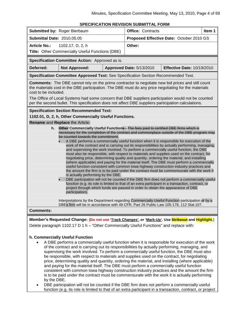
Specification Section Recommended Text: 1102.01, D, 2, h, Other Commercially Useful Functions. Rename and Replace the Article:
h. Other Commercially Useful Functions - The fees paid to certified DBE firms which is necessary for the completion of the contract and commonplace outside of the DBE program may be counted towards the commitment. • A DBE performs a commercially useful function when it is responsible for execution of the
work of the contract and is carrying out its responsibilities by actually performing, managing, and supervising the work involved. To perform a commercially useful function, the DBE must also be responsible, with respect to materials and supplies used on the contract, for negotiating price, determining quality and quantity, ordering the material, and installing (where applicable) and paying for the material itself. The DBE must perform a commercially useful function consistent with common Iowa highway construction industry practices and the amount the firm is to be paid under the contract must be commensurate with the work it is actually performing by the DBE.
• DBE participation will not be counted if the DBE firm does not perform a commercially useful function (e.g. its role is limited to that of an extra participant in a transaction, contract, or project through which funds are passed in order to obtain the appearance of DBE participation).
Interpretations by the Department regarding Commercially Useful Function participation of by a
DBEs firm will be in accordance with 49 CFR, Part 26 Public Law 105-178, 112 Stat.107. Comments:
Member’s Requested Change: (Do not use ‘Track Changes’, or ‘Mark-Up’. Use Strikeout and Highlight.) Delete paragraph 1102.17 D 1 h – “Other Commercially Useful Functions” and replace with: h. Commercially Useful Function
• A DBE performs a commercially useful function when it is responsible for execution of the work of the contract and is carrying out its responsibilities by actually performing, managing, and supervising the work involved. To perform a commercially useful function, the DBE must also be responsible, with respect to materials and supplies used on the contract, for negotiating price, determining quality and quantity, ordering the material, and installing (where applicable) and paying for the material itself. The DBE must perform a commercially useful function consistent with common Iowa highway construction industry practices and the amount the firm is to be paid under the contract must be commensurate with the work it is actually performing by the DBE.
• DBE participation will not be counted if the DBE firm does not perform a commercially useful function (e.g. its role is limited to that of an extra participant in a transaction, contract, or project

Minutes, Specification Committee Meeting, May 13, 2010, Page 5 of 69
through which funds are passed in order to obtain the appearance of DBE participation). Interpretations by the Department regarding Commercially Useful Function participation by a DBE firm will be in accordance with 49 CFR, Part 26 Public Law 105-178, 112 Stat.107. Reason for Revision: Directive from Becky Hiatt, Iowa Division, FHWA in letter dated April 16, 2010 to resolve an issue found by the National Review Team November 2009 finding.
County or City Input Needed (X one) Yes No X
Comments:
Industry Input Needed (X one) Yes No X
Industry Notified: Yes No X Industry Concurrence: Yes No X
Comments: If approved this will be discussed at the September 7, 2010 AGC/DBE/IDOT Task Force Meeting.

Minutes, Specification Committee Meeting, May 13, 2010, Page 6 of 69
SPECIFICATION REVISION SUBMITTAL FORM Submitted by: Deanna Maifield Office: Design Item 2
Submittal Date: 4/30/10 Proposed Effective Date: 10/19/10
Section No.: 2212.04, C Title: Partial Depth Repair Patches Section No.: 2212.05, C, 1 Title: Partial Depth Repair Patches
Other:
Specification Committee Action: Approved with changes.
Deferred: Not Approved: Approved Date: 5/13/2010 Effective Date: 10/19/2010
Specification Committee Approved Text: 2212.04, C, Partial Depth Repair Patches.
Replace the article: Computed in square yards (square meters) to the nearest 0.1 square yards (0.1 m2) from measurements of the patch areas. 1. PCC: The Engineer will calculate the area of each patch in square feet (square meters) from surface
measurements. The area of each patch less than 1 square foot (0.1 m2) will be counted as 1 square foot (0.1 m2)
2. HMA: The Engineer will measure the area for each patch and the weight (mass) of HMA placed in
partial depth repair patches according to Article 2303.04. Asphalt binder and tack coat will not be measured separately for payment.
3. If the patch area is increased by the Contractor to accommodate milling equipment, only the area
designated by the Engineer will be measured for payment. 2212.05, C, Partial Depth Repair Patches.
Replace Article 1: PCC: Per square yard foot (square meters).
Renumber Article 2 as Article 3. Add as the second Article:
2. HMA: a. Per square yard (square meter). b. Per ton (megagram).
Comments: The Office of Contracts asked why the language was different from Section 2530. Changes were made to be more consistent with Section 2530.
Specification Section Recommended Text: 2212.04, C, Partial Depth Repair Patches.
Replace the article: Computed in square yards (square meters) to the nearest 0.1 square yards (0.1 m2) from measurements of the patch areas. 1. PCC: The Engineer will calculate the area of each patch in square feet (square meters). 2. HMA: The Engineer will calculate the area in square yards (square meters) and the weight (mass) of
HMA placed in partial depth repair patches. 2212.05, C, Partial Depth Repair Patches.
Replace Article 1: PCC: Per square yard foot (square meters).
Renumber Article 2 as Article 3. Add as the second Article:
2. HMA:

Minutes, Specification Committee Meeting, May 13, 2010, Page 7 of 69
a. Per square yard (square meter). b. Per ton (megagram).
Comments:
Member’s Requested Change: (Do not use ‘Track Changes’, or ‘Mark-Up’. Use Strikeout and Highlight.) Article 2212.04, C, Partial Depth Repair Patches.
Replace the article:
Computed in square yards (square meters) to the nearest 0.1 square yards (0.1 m2) from measurements of the patch areas. 1. The Engineer will calculate the area of each patch in square feet (square meters). 2. HMA: The Engineer will calculate the area in square yards (square meters) and the weight (mass) of
HMA placed in partial depth repair patches. Article 2212.04, C, Partial Depth Repair Patches.
Replace the first paragraph:
1. Per square yard (square meters). 1. PCC: Per square foot (square meter).
Add as the second paragraph:
2. HMA: a. Per square yard (square meter). b. Per ton (megagram).
Renumber Paragraph 2 as Paragraph 3.
Reason for Revision: Article 2212.03, B, 2, d refers to Section 2530 for construction of partial depth repair patches. The Office of Design is proposing the MOM and BOP match as well. Tab 102-14 will be updated to reflect these changes.
County or City Input Needed (X one) Yes No X
Comments:
Industry Input Needed (X one) Yes No X
Industry Notified: Yes No X Industry Concurrence: Yes No
Comments:

Minutes, Specification Committee Meeting, May 13, 2010, Page 8 of 69
SPECIFICATION REVISION SUBMITTAL FORM Submitted by: Donna Buchwald Office: Local Systems Item 3
Submittal Date: April 29, 2010 Proposed Effective Date: October 19, 2010
Article No.: 2214.05 Title: Basis of Payment (Pavement Scarification) Article No.: 2401.05 Title: Basis of Payment (Removal of Existing Structures) Article No.: 2505.05, D Title: Basis of Payment (Removal of Guardrail)
Other:
Specification Committee Action: Approved as is.
Deferred: Not Approved: Approved Date: 5/13/2010 Effective Date: 10/19/2010
Specification Committee Approved Text: See Specification Section Recommended Text.
Comments: None.
Specification Section Recommended Text: 2214.05, BASIS OF PAYMENT.
Add as the third sentence: If the scarified pavement materials will become the property of the Contracting Authority, delivery and stockpiling of the material shall be according to Section 2555.
2401.05, B. Replace the first bullet:
Furnishing all material, equipment, and labor and for performance of all work necessary for proper storage of salvaged material or for removal of the old structure from the project, and
Add as the second bullet:
If the existing structure will become the property of the Contracting Authority, payment for proper storage, salvage, and delivery of the structure shall be according to Section 2555.
2505.05, D, 2
Replace the first sentence: Payment includes hauling salvaged material to the stockpile site. If the guard rail materials are salvaged, payment for hauling and stockpiling the materials shall be according to Section 2555.
Comments:
Member’s Requested Change: (Do not use ‘Track Changes’, or ‘Mark-Up’. Use Strikeout and Highlight.) 2214.05, Pavement Scarification
Replace the second sentence: Payments are full compensation for furnishing materials, (including water), equipment, and labor necessary to complete the work according to the contract documents. including If the scarified pavement materials will become the property of the Contracting Authority, the delivery and stockpiling of the material shall be according to Section 2555; otherwise, payment for salvaging, stockpiling, and removal of excess material and debris according to Article 1104.08.
2401.05, B, Removal of Existing Structures
Replace the first bullet: Furnishing all material, equipment, and labor and for performance of all work necessary for proper storage of salvaged material or for removal of the old structure from the project, and
Minutes, Specification Committee Meeting, May 13, 2010, Page 9 of 69
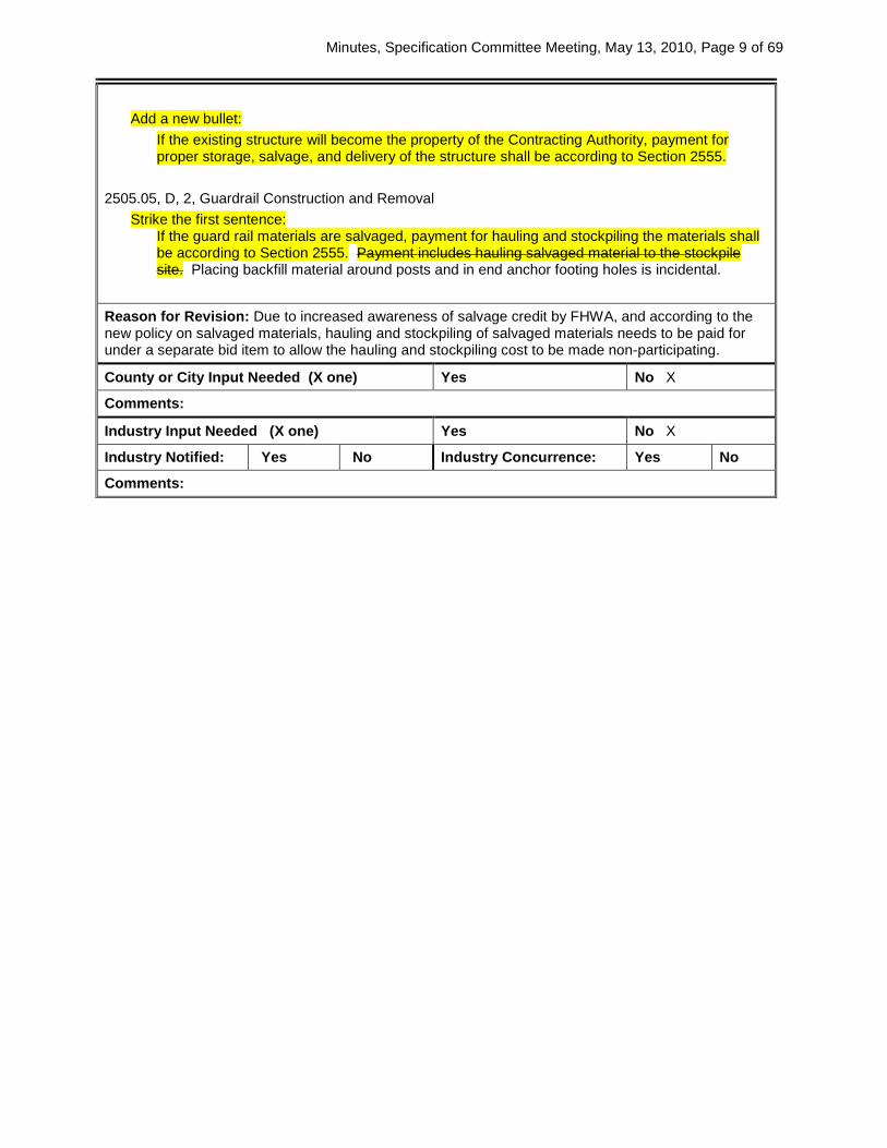
Add a new bullet:
If the existing structure will become the property of the Contracting Authority, payment for proper storage, salvage, and delivery of the structure shall be according to Section 2555.
2505.05, D, 2, Guardrail Construction and Removal
Strike the first sentence: If the guard rail materials are salvaged, payment for hauling and stockpiling the materials shall be according to Section 2555. Payment includes hauling salvaged material to the stockpile site. Placing backfill material around posts and in end anchor footing holes is incidental.
Reason for Revision: Due to increased awareness of salvage credit by FHWA, and according to the new policy on salvaged materials, hauling and stockpiling of salvaged materials needs to be paid for under a separate bid item to allow the hauling and stockpiling cost to be made non-participating.
County or City Input Needed (X one) Yes No X
Comments:
Industry Input Needed (X one) Yes No X
Industry Notified: Yes No Industry Concurrence: Yes No
Comments:

Minutes, Specification Committee Meeting, May 13, 2010, Page 10 of 69
SPECIFICATION REVISION SUBMITTAL FORM Submitted by: Jim Berger Office: Materials Item 4
Submittal Date: 5/04/10 Proposed Effective Date: October 2010
Article No.: 2303.02, B, 1, b Title: Hot Mix Asphalt Mixtures
Other:
Specification Committee Action: Approved as is.
Deferred: Not Approved: Approved Date: 5/13/2010 Effective Date: 10/19/2010
Specification Committee Approved Text: See Specification Section Recommended Text.
Comments: District 6 believes there may be some issues with L-3 friction pavements, but those will be addressed later.
Specification Section Recommended Text: 2303.02, B, 1, b.
Add the following to the end of the first paragraph: Limestone aggregate sources defined as containing less than 15% magnesium oxide (MgO) are identified in Materials I.M. T203.
2303.02, B, 1, b, 1, Friction Classification L-2.
Replace the Article: a) If 40% or more of the total aggregate is limestone, Uuse a combined aggregate such that:
• 1. At least 80% of the combined aggregate retained on the No. 4 (4.75 mm) sieve is Type 4 or better friction aggregate, and
• 2. At least 25 30% of the combined aggregate retained on the No. 4 (4.75 mm) sieve is Type 2 or better friction aggregate.,
• 3. At least 25% of the combined aggregate passing the No. 4 (4.75 mm) sieve is Type 2 or better friction aggregate, and
• 4. The fineness modulus of the combined Type 2 aggregate is at least 1.0. Calculations for fineness modulus are shown in Materials I.M. 501.
b) If less than 40% of the total aggregate is a limestone, use a combined aggregate such that: 1. At least 80% of the combined aggregate retained on the No. 4 (4.75 mm) sieve is Type 4 or
better friction aggregate, and 2. At least 25% of the combined aggregate retained on the No. 4 (4.75 mm) sieve is Type 2 or
better friction aggregate, and 3. The fineness modulus of the combined Type 2 aggregate is at least 1.0. Calculations for
fineness modulus are shown in Materials I.M. 501. Comments:
Member’s Requested Change: (Do not use ‘Track Changes’, or ‘Mark-Up’. Use Strikeout and Highlight.) b. When frictional classification of the coarse aggregate is required, the contract documents will
specify the friction level and location. Furnish friction aggregate from sources identified in Materials I.M. T203. Limestone aggregate sources defined as containing less than 15% magnesium oxide (MgO) are identified in Materials I.M. T203. 1) Friction Classification L-2.
A) If 40% or more of the total aggregate is a limestone, Uuse a combined aggregate such that:
1. At least 80% of the combined aggregate retained on the No. 4 (4.75 mm) sieve is Type 4 or better friction aggregate, and
2. At least 2530% of the combined aggregate retained on the No. 4 (4.75 mm) sieve is Type 2 or better friction aggregate., and
3. At least 25% of the combined aggregate passing the No. 4 (4.75 mm) sieve is Type 2 or better friction aggregate, and
4. The fineness modulus of the combined Type 2 aggregate is at least 1.0. Calculations for fineness modulus are shown in Materials I.M. 501.
B) If less than 40% of the total aggregate is a limestone, use a combined aggregate such
Minutes, Specification Committee Meeting, May 13, 2010, Page 11 of 69
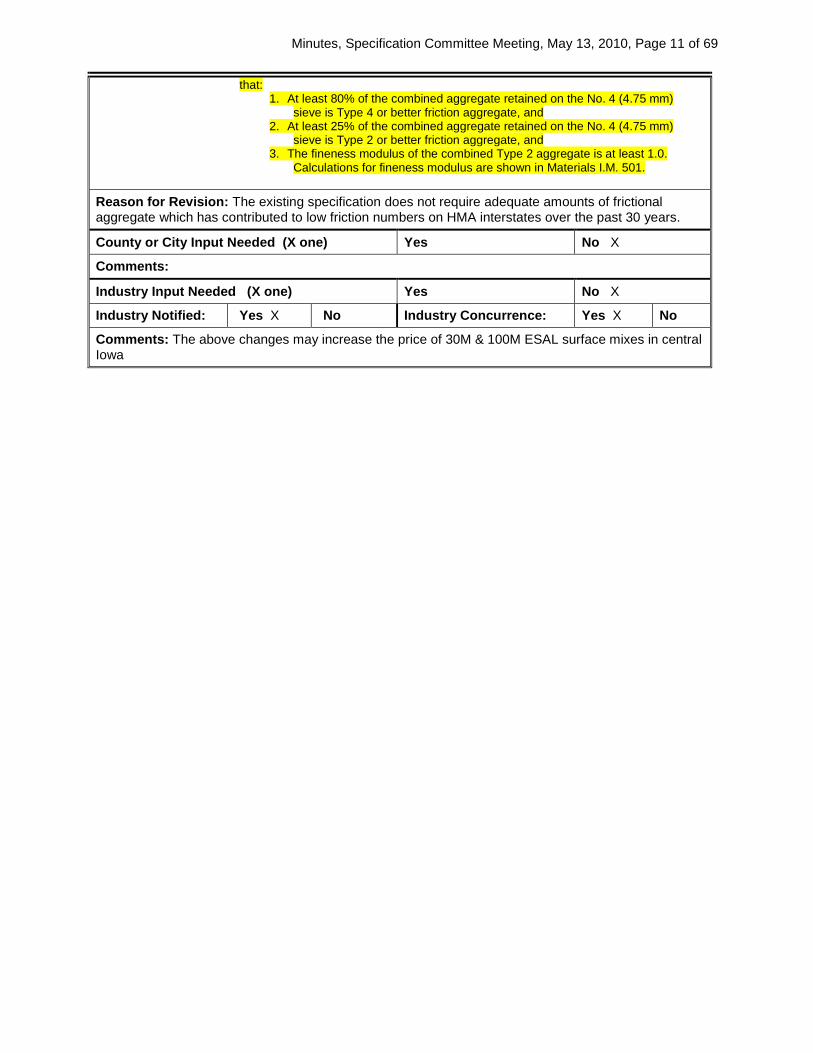
that: 1. At least 80% of the combined aggregate retained on the No. 4 (4.75 mm)
sieve is Type 4 or better friction aggregate, and 2. At least 25% of the combined aggregate retained on the No. 4 (4.75 mm)
sieve is Type 2 or better friction aggregate, and 3. The fineness modulus of the combined Type 2 aggregate is at least 1.0.
Calculations for fineness modulus are shown in Materials I.M. 501.
Reason for Revision: The existing specification does not require adequate amounts of frictional aggregate which has contributed to low friction numbers on HMA interstates over the past 30 years.
County or City Input Needed (X one) Yes No X
Comments:
Industry Input Needed (X one) Yes No X
Industry Notified: Yes X No Industry Concurrence: Yes X No
Comments: The above changes may increase the price of 30M & 100M ESAL surface mixes in central Iowa

Minutes, Specification Committee Meeting, May 13, 2010, Page 12 of 69
SPECIFICATION REVISION SUBMITTAL FORM Submitted by: Jim Berger Office: Materials Item 5
Submittal Date: 5/04/10 Proposed Effective Date: October 2010
Article No.: 2303.02, E, 2, h, 1 Title: Hot Mix Asphalt Mixtures
Other:
Specification Committee Action: Approved with changes.
Deferred: Not Approved: Approved Date: 5/13/2010 Effective Date: 10/19/2010
Specification Committee Approved Text: 2303.02, E, 2, h, 1, Hydrated Lime.
Replace the first sentence of the Article: Meet the requirements of AASHTO M 303, Type I or ASTM C 1097, Type S.
Comments: The “C” was omitted from the ASTM designation.
Specification Section Recommended Text: 2303.02, E, 2, h, 1, Hydrated Lime.
Replace the first sentence of the Article: Meet the requirements of AASHTO M 303, Type I or ASTM 1097, Type S.
Comments:
Member’s Requested Change: (Do not use ‘Track Changes’, or ‘Mark-Up’. Use Strikeout and Highlight.) Add the following to the first sentence: Meet the requirements of AASHTO M 303, Type I or ASTM 1097, Type S. Reason for Revision: A source of Dolomitic lime is now readily available from Nebraska; however, only high-calcium lime is currently allowed. This revision allows the dolomitic lime to also be used as an anti-stripping agent.
County or City Input Needed (X one) Yes No X
Comments:
Industry Input Needed (X one) Yes No X
Industry Notified: Yes No X Industry Concurrence: N/A
Yes No
Comments:

Minutes, Specification Committee Meeting, May 13, 2010, Page 13 of 69
SPECIFICATION REVISION SUBMITTAL FORM Submitted by: John Smythe / Jeff Schmitt Office: Construction Item 6
Submittal Date: 04-12-2010 Proposed Effective Date: October 2010 GS
Article No.: 2303.03, C, 7, f Title: Paved HMA Shoulders (HMA Mixtures)
Other: Changes shown below are for DS-09040, which will be incorporated into Section 2303 as part of the October 2010 GS.
Specification Committee Action: Approved as is.
Deferred: Not Approved: Approved Date: 5/13/2010 Effective Date: 10/19/2010
Specification Committee Approved Text: See Specification Section Recommended Text.
Comments: None.
Specification Section Recommended Text: 2303.03, C, 7, f, Paved HMA Shoulders.
Replace the Article: 1) Compact paved HMA shoulders using one of the following methods:
a) Class II compaction (Article 2303.03, C, 5, c), b) Rolling pattern established during the first day of shoulder placement to achieve Class
1 compaction (Article2303.03, C, 5, b) or c) Same rolling pattern established for adjoining mainline or ramp driving lanes, as
determined by density coring. 2) Shoulder area will not be included in PWL calculations for field voids on adjoining mainline
or ramp driving lane. A price adjustment may be applied to shoulder areas that do not adhere to the established roller pattern.
Comments: Revisions approved at the March 11, 2010 Spec. Committee meeting are not highlighted.
Member’s Requested Change: (Do not use ‘Track Changes’, or ‘Mark-Up’. Use Strikeout and Highlight.) Revise the following paragraphs as shown below:
3) Compact paved HMA shoulders using one of the following methods: d) Class II compaction (Article 2303.03, C, 5, c), e) Rolling pattern established during the first day of shoulder placement to achieve Class 1C
compaction (Article2303.03, C, 5, b, 3) or f) Same rolling pattern established for adjoining mainline or ramp driving lanes, as
determined by density coring. 4) Shoulder area will not be included in PWL calculations for density price adjustment field voids
on adjoining mainline or ramp driving lane. A price adjustment may be applied to shoulder areas that do not adhere to the established roller pattern.
Reason for Revision: To clarify that paved ramp shoulders are to be handled in the same manner as paved shoulders adjacent to mainline driving lanes, regarding coring for field voids determination and PWL calculations.
County or City Input Needed (X one) Yes No X
Comments:
Industry Input Needed (X one) Yes No X
Industry Notified: Yes No X Industry Concurrence: Yes No X
Comments:

Minutes, Specification Committee Meeting, May 13, 2010, Page 14 of 69
SPECIFICATION REVISION SUBMITTAL FORM Submitted by: John Smythe / Jeff Schmitt Office: Construction Item 7
Submittal Date: 04-12-2010 Proposed Effective Date: October 2010 GS
Article No.: 2318.03, J Title: Limitations (Cold In-Place Recycled Asphalt Pavement)
Other:
Specification Committee Action: Approved as is.
Deferred: Not Approved: Approved Date: 5/13/2010 Effective Date: 10/19/2010
Specification Committee Approved Text: See Specification Section Recommended Text.
Comments:
Specification Section Recommended Text: 2318.03, CONSTRUCTION.
Add the following Article: J. Limitations.
When HMA resurfacing is part of the contract, cover cold in-place recycled surfaces with at least one full lift of HMA prior to winter shutdown.
Comments:
Member’s Requested Change: (Do not use ‘Track Changes’, or ‘Mark-Up’. Use Strikeout and Highlight.) Add the following to paragraph to Article 2318.03: J. Limitations When HMA resurfacing is part of the contract, cover all cold in-place recycled surfaces with at least one full lift of HMA prior to winter shutdown.
Reason for Revision: To reinstate a previous specification requirement (limitation) that was omitted from the Cold In-Place Recycling specification during rewrite for the new specification book.
County or City Input Needed (X one) Yes No X
Comments:
Industry Input Needed (X one) Yes No X
Industry Notified: Yes No X Industry Concurrence: Yes No X
Comments:

Minutes, Specification Committee Meeting, May 13, 2010, Page 15 of 69
SPECIFICATION REVISION SUBMITTAL FORM Submitted by: Jim Berger Office: Materials Item 8
Submittal Date: April, 2010 Proposed Effective Date: October, 2010
Article No.: 2407.03, B, 4 Title: Concrete
Other:
Specification Committee Action: Approved as is.
Deferred: Not Approved: Approved Date: 5/13/2010 Effective Date: 10/19/2010
Specification Committee Approved Text: See Specification Section Recommended Text.
Comments: None.
Specification Section Recommended Text: 2407.03, B, 4.
Replace Articles a and b: a. Submit to the Engineer ASTM C 1202 results from mix samples taken and tested by an independent
laboratory. The results shall be 2500 1500 coulombs or less when cured using accelerated moist curing.
b. Contact the Engineer and arrange for a trial batch. The Engineer producer certified technician will shall cast 4 inch by 8 inch (100 mm by 200 mm) cylinders for testing by the Materials Laboratory. The ASTM C 1202 results shall be 2500 1500 coulombs or less when cured using accelerated moist curing.
Comments:
Member’s Requested Change: (Do not use ‘Track Changes’, or ‘Mark-Up’. Use Strikeout and Highlight.) 4. If using HPC for prestressed concrete beams, use a mix design that has been evaluated according to
ASTM C1202 and approved by the engineer. To obtain mix design approval either: a. Submit to the engineer ASTM C1202 results from mix samples taken and tested by an
independent laboratory. The results shall be 2500 1500 coulombs or less when cured using accelerated moist curing.
b. Contact the engineer and arrange for a trial batch. The engineer producer certified technician will cast 4 inch by 8 inch cylinders for testing by the Materials Laboratory. The ASTM C1202 results shall be 2500 1500 coulombs or less when cured using accelerated moist curing.
apply the following additional specifications: a. The Contractor may submit up to two trial batches of concrete per project at no cost. The
Contractor will be charged $500 for each additional trial batch submittal or resubmittal. Submit trial batch concrete that is of a size and mix typically used in day-to-day operations and is made at least 60 calendar days prior to placement. Ensure the trial batch concrete design produces a slump within ± 4 inches (100 mm) of placement slump.
b. The District Materials Engineer may waive trial batch testing for a mix, provided the mix was previously tested and resulted in satisfactory mix properties. Adjustments to a previously approved mix, not requiring a new trial batch, will be at the discretion of the District Materials Engineer.
c. Notify the District Materials Engineer, Plant Inspector, and Materials Structural Engineer at least 7 calendar days prior to batching. Ensure the Plant Inspector casts all samples from the trial batch concrete.
d. The Contracting Authority will test trial batch concrete permeability. Two permeability samples will be cast in 4 inch by 8 inch (100 mm by 200 mm) plastic cylinder molds and capped. Within 5 calendar days of casting, the samples will be delivered to the Central Materials Testing Laboratory. The samples will remain in their plastic molds with lids until delivered. The samples will be stripped of their molds and wet cured to an age of 7 days in the moist room. After 7 days, the samples will be submerged in water heated to 100°F (37.7°C) until an age of 28 days or more. Two test specimens will be obtained from each cylinder. Permeability will be tested in accordance with AASHTO T277 at 28 days or more. A coulomb reading of 2500 or less, based on the average of four test results, is considered acceptable.
e. Trial batch materials, proportions, and test results will be reported to the District Materials Engineer for approval.

Minutes, Specification Committee Meeting, May 13, 2010, Page 16 of 69
Reason for Revision: Lower the coulomb reading to 1500 make the concrete more durable
County or City Input Needed (X one) Yes No x
Comments:
Industry Input Needed (X one) Yes No X
Industry Notified: Yes X No Industry Concurrence: Yes X No
Comments:

Minutes, Specification Committee Meeting, May 13, 2010, Page 17 of 69
SPECIFICATION REVISION SUBMITTAL FORM Submitted by: J. Berger Office: Materials Item 9
Submittal Date: 4/28/10 Proposed Effective Date: October, 2010
Article No.: 2413.02, D, 2 Title: Class HPC-O High Performance Concrete (Materials)
Other:
Specification Committee Action: Approved as is.
Deferred: Not Approved: Approved Date: 5/13/2010 Effective Date: 10/19/2010
Specification Committee Approved Text: See Specification Section Recommended Text.
Comments: The Office of Materials asked if the slump limits should have “.0” added, i.e. “1.0 inch”. There will be a new Materials I.M. that defines rounding for materials testing per a new ASTM. In this case, a test result of 0.5 inch slump would meet the 1 inch minimum specified and 5.25 inches would meet the 5 inch maximum. It was decided that we will wait and handle materials testing precision all at one time instead of as we go, most likely when the next Standard Specifications book is issued (October 2011). This will affect Materials I.M.’s and other Iowa DOT documents also.
Specification Section Recommended Text: 2413.02, D, 2, a.
Replace the first sentence of the Article: A slump of 1 inch (25 mm) to 3 4 inches (75 100 mm), measured according to Materials I.M. 317, with a maximum of 4 5 inches (100 125 mm).
2413.02, D, 2, b. Replace the first sentence of the Article:
Use a mid-range water reducing admixture meeting the requirements of Materials I.M. 403, Appendix C and a retarder listed in Materials I.M. 403 Appendix G. When the expected haul time is less than 30 minutes or the maximum air temperature expected is less than 75°F (24°C), addition of a retarder is not required.
2413.02, D, 2, e. Replace the Article:
e. Limit fly ash substitution to 15 20% replacement by weight. Comments:
Member’s Requested Change: (Do not use ‘Track Changes’, or ‘Mark-Up’. Use Strikeout and Highlight.) 2. Class HPC-O High Performance Concrete.
Meet the requirements of Materials I.M. 529 and the following: a. A slump of 1 inch (25 mm) to 4 3 inches (75 mm), measured according to Materials I.M. 317, with
a maximum of 5 4 inches (100 mm). Commence testing for concrete slump from a continuous mixer within 2 to 4 minutes after the concrete is discharged. Before placing ready mix concrete, test the slump.
b. Use a mid-range water reducing admixture meeting the requirements of Materials I.M. 403, Appendix C and a retarder listed in Materials I.M. 403 Appendix G. When the expected haul time is less than 30 minutes or the maximum air temperature expected is less than 75 deg, F (24 deg. C), addition of a retarder is not required. The intent of the mid-range water reducer is to achieve a workable, dense, and low w/c ratio concrete. The Engineer may approve other admixtures or combinations of admixtures and dosages to achieve a workable low w/c ratio mix.
c. Air content is to be the same as required for Class O PCC. d. Use Type IS or Type IP cement. If Type I/II is used, 25% replacement with GGBFS is required. e. Limit fly ash substitution to 20 15% replacement by weight.
Reason for Revision: The HPC-O is fairly new for the Iowa contractors. The change should make the specification clearer. For most HPC-O projects, the haul/discharge time and/or the temperature are such that some mid-range water reducers can’t maintain slump without some additional help. There have been reports that water is being added at the bridge to recover the slump at the expense of the

Minutes, Specification Committee Meeting, May 13, 2010, Page 18 of 69
w/cm ratio. The maximum slump is higher than desirable but may occasionally occur while using mid-range water reducers. The change in the fly ash substitution is to make it consistent with the HPC for structures.
County or City Input Needed (X one) Yes No X
Comments:
Industry Input Needed (X one) Yes X No
Industry Notified: Yes No X Industry Concurrence: Yes No
Comments: Since the HPC-O is still fairly new, some time may be needed to try out the changes. The specification does allow the contractor to propose changes to the admixtures. The goal is to keep the w/cm ratio low to reduce the risk of shrinkage.

Minutes, Specification Committee Meeting, May 13, 2010, Page 19 of 69
SPECIFICATION REVISION SUBMITTAL FORM Submitted by: John Smythe/Wayne Sunday Office: Construction Item 10
Submittal Date: April 2, 2010 Proposed Effective Date: October 2010
Article No.: 2413.03, E, 1 Title: Repairs
Other:
Specification Committee Action: Approved with changes.
Deferred: Not Approved: Approved Date: 5/13/2010 Effective Date: 10/19/2010
Specification Committee Approved Text: 2413.03, E, 1, b.
Renumber Article 8 to Article 10. Add new Articles 8 and 9:
8) Deck repair concrete, described in Article 2413.02, or Class C structural concrete, meeting requirements of Sections 2403 and 2412, may be used when individual placements are placed to the lower boundary for the superimposed overlay.
9) Allow the partial placement to cure for 72 hours.
2413.03, E, 1, c. Replace the Article:
c. For Class A repair areas:, 1) Uuse Class O or Class HPC-O concrete when repair concrete is placed monolithically with the
overlay. 2) Deck repair concrete, described in Article 2413.02, or Class C structural concrete, meeting
requirements of Sections 2403 and 2412, may be used when individual placements are placed to the lower boundary for the superimposed overlay.
3) Allow the partial placement to cure for 72 hours. 4) After the cure, surface dry, sandblast or shot blast and clean individual placements before
applying the overlay course or grout. Comments: The Office of Bridges and Structures pointed out that items 3 and 4 in Article 2413.03, E, 1, c, also apply to Class B repairs and not Class A. Item 4 is already listed for Class B repairs, so that item will be deleted for Class A.
Specification Section Recommended Text: 2413.03, E, 1, b.
Renumber Article 8 to Article 9. Add new Article 8:
8) Deck repair concrete, described in Article 2413.02, or Class C structural concrete, meeting requirements of Sections 2403 and 2412, may be used when individual placements are placed to the lower boundary for the superimposed overlay.
2413.03, E, 1, c.
Delete Article 2: 2) Deck repair concrete, described in Article 2413.02, or Class C structural concrete, meeting
requirements of Sections 2403 and 2412, may be used when individual placements are placed to the lower boundary for the superimposed overlay.
Comments:
Member’s Requested Change: (Do not use ‘Track Changes’, or ‘Mark-Up’.Use Strikeout and Highlight. E. Placing and Finishing.
1. Repairs. Apply the following to repair work: a. Although repair classes are considered to begin 1/4 inch (5 mm) below the original concrete
surface, place repair concrete monolithically with the overlay course, except as described for
Minutes, Specification Committee Meeting, May 13, 2010, Page 20 of 69
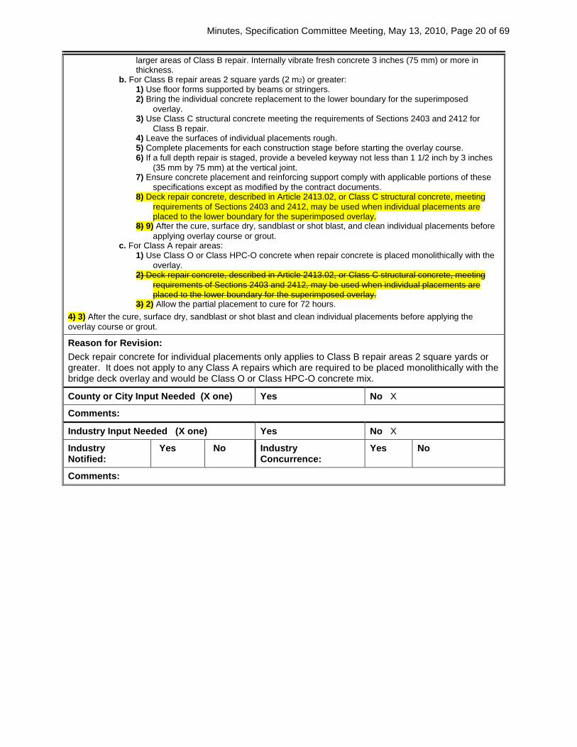
larger areas of Class B repair. Internally vibrate fresh concrete 3 inches (75 mm) or more in thickness.
b. For Class B repair areas 2 square yards (2 m2) or greater: 1) Use floor forms supported by beams or stringers. 2) Bring the individual concrete replacement to the lower boundary for the superimposed
overlay. 3) Use Class C structural concrete meeting the requirements of Sections 2403 and 2412 for
Class B repair. 4) Leave the surfaces of individual placements rough. 5) Complete placements for each construction stage before starting the overlay course. 6) If a full depth repair is staged, provide a beveled keyway not less than 1 1/2 inch by 3 inches
(35 mm by 75 mm) at the vertical joint. 7) Ensure concrete placement and reinforcing support comply with applicable portions of these
specifications except as modified by the contract documents. 8) Deck repair concrete, described in Article 2413.02, or Class C structural concrete, meeting
requirements of Sections 2403 and 2412, may be used when individual placements are placed to the lower boundary for the superimposed overlay.
8) 9) After the cure, surface dry, sandblast or shot blast, and clean individual placements before applying overlay course or grout.
c. For Class A repair areas: 1) Use Class O or Class HPC-O concrete when repair concrete is placed monolithically with the
overlay. 2) Deck repair concrete, described in Article 2413.02, or Class C structural concrete, meeting
requirements of Sections 2403 and 2412, may be used when individual placements are placed to the lower boundary for the superimposed overlay.
3) 2) Allow the partial placement to cure for 72 hours. 4) 3) After the cure, surface dry, sandblast or shot blast and clean individual placements before applying the overlay course or grout.
Reason for Revision: Deck repair concrete for individual placements only applies to Class B repair areas 2 square yards or greater. It does not apply to any Class A repairs which are required to be placed monolithically with the bridge deck overlay and would be Class O or Class HPC-O concrete mix.
County or City Input Needed (X one) Yes No X
Comments:
Industry Input Needed (X one) Yes No X
Industry Notified:
Yes No Industry Concurrence:
Yes No
Comments:
Minutes, Specification Committee Meeting, May 13, 2010, Page 21 of 69
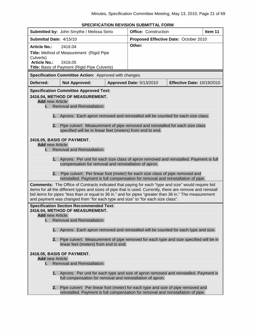
SPECIFICATION REVISION SUBMITTAL FORM Submitted by: John Smythe / Melissa Serio Office: Construction Item 11
Submittal Date: 4/15/10 Proposed Effective Date: October 2010
Article No.: 2416.04 Title: Method of Measurement (Rigid Pipe Culverts) Article No.: 2416.05 Title: Basis of Payment (Rigid Pipe Culverts)
Other:
Specification Committee Action: Approved with changes.
Deferred: Not Approved: Approved Date: 5/13/2010 Effective Date: 10/19/2010
Specification Committee Approved Text: 2416.04, METHOD OF MEASUREMENT.
Add new Article: I. Removal and Reinstallation:
1. Aprons: Each apron removed and reinstalled will be counted for each size class.
2. Pipe culvert: Measurement of pipe removed and reinstalled for each size class
specified will be in linear feet (meters) from end to end.
2416.05, BASIS OF PAYMENT. Add new Article:
I. Removal and Reinstallation: 1. Aprons: Per unit for each size class of apron removed and reinstalled. Payment is full
compensation for removal and reinstallation of apron.
2. Pipe culvert: Per linear foot (meter) for each size class of pipe removed and reinstalled. Payment is full compensation for removal and reinstallation of pipe.
Comments: The Office of Contracts indicated that paying for each “type and size” would require bid items for all the different types and sizes of pipe that is used. Currently, there are remove and reinstall bid items for pipes “less than or equal to 36 in.” and for pipes “greater than 36 in.” The measurement and payment was changed from “for each type and size” to “for each size class”. Specification Section Recommended Text: 2416.04, METHOD OF MEASUREMENT.
Add new Article: I. Removal and Reinstallation:
1. Aprons: Each apron removed and reinstalled will be counted for each type and size.
2. Pipe culvert: Measurement of pipe removed for each type and size specified will be in
linear feet (meters) from end to end.
2416.05, BASIS OF PAYMENT. Add new Article:
I. Removal and Reinstallation: 1. Aprons: Per unit for each type and size of apron removed and reinstalled. Payment is
full compensation for removal and reinstallation of apron.
2. Pipe culvert: Per linear foot (meter) for each type and size of pipe removed and reinstalled. Payment is full compensation for removal and reinstallation of pipe.

Minutes, Specification Committee Meeting, May 13, 2010, Page 22 of 69
Comments:
Member’s Requested Change: (Do not use ‘Track Changes’, or ‘Mark-Up’. Use Strikeout and Highlight.) 2416.04, I. Add new Article:
I. Removal and Reinstallation: 1. Aprons: Each apron removed and reinstalled will be counted for each type and
size 2. Pipe culvert: Measurement of pipe removed for each type and size specified will
be in linear feet (meters) from end to end. 2416.05, I. Add new Article:
I. Removal and Reinstallation: 1. Aprons: Per unit for each type and size of apron removed and reinstalled. Payment is
full compensation for removal and reinstallation of apron. 2. Pipe culvert: Per linear foot (meter) for each type and size of pipe removed and
reinstalled. Payment is full compensation for removal and reinstallation of pipe.
Reason for Revision: When these items have been a part of the project, the MOM and BOP have been included in the Estimate Reference Information in the contract drawings. Recommendation is to add the MOM and BOP for these items to the Standard Specifications.
County or City Input Needed (X one) Yes No X
Comments: None
Industry Input Needed (X one) Yes No X
Industry Notified: Yes No Industry Concurrence: Yes No
Comments: None
Minutes, Specification Committee Meeting, May 13, 2010, Page 23 of 69
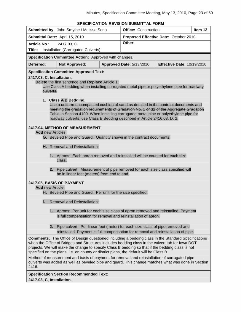
SPECIFICATION REVISION SUBMITTAL FORM Submitted by: John Smythe / Melissa Serio Office: Construction Item 12
Submittal Date: April 15, 2010 Proposed Effective Date: October 2010
Article No.: 2417.03, C Title: Installation (Corrugated Culverts)
Other:
Specification Committee Action: Approved with changes.
Deferred: Not Approved: Approved Date: 5/13/2010 Effective Date: 10/19/2010
Specification Committee Approved Text: 2417.03, C, Installation.
Delete the first sentence and Replace Article 1: Use Class A bedding when installing corrugated metal pipe or polyethylene pipe for roadway culverts. 1. Class A B Bedding.
Use a uniform uncompacted cushion of sand as detailed in the contract documents and meeting the gradation requirements of Gradation No. 1 or 32 of the Aggregate Gradation Table in Section 4109. When installing corrugated metal pipe or polyethylene pipe for roadway culverts, use Class B Bedding described in Article 2416.03, D, 2.
2417.04, METHOD OF MEASUREMENT.
Add new Articles: G. Beveled Pipe and Guard: Quantity shown in the contract documents.
H. Removal and Reinstallation:
1. Aprons: Each apron removed and reinstalled will be counted for each size
class.
2. Pipe culvert: Measurement of pipe removed for each size class specified will be in linear feet (meters) from end to end.
2417.05, BASIS OF PAYMENT.
Add new Article: H. Beveled Pipe and Guard: Per unit for the size specified.
I. Removal and Reinstallation:
1. Aprons: Per unit for each size class of apron removed and reinstalled. Payment
is full compensation for removal and reinstallation of apron.
2. Pipe culvert: Per linear foot (meter) for each size class of pipe removed and reinstalled. Payment is full compensation for removal and reinstallation of pipe.
Comments: The Office of Design questioned including a bedding class in the Standard Specifications when the Office of Bridges and Structures includes bedding class in the culvert tab for Iowa DOT projects. We will make the change to specify Class B bedding so that if the bedding class is not specified on the plans, i.e. on county or district plans, the default will be Class B. Method of measurement and basis of payment for removal and reinstallation of corrugated pipe culverts was added as well as beveled pipe and guard. This change matches what was done in Section 2416.
Specification Section Recommended Text: 2417.03, C, Installation.

Minutes, Specification Committee Meeting, May 13, 2010, Page 24 of 69
Delete the first sentence and Replace Article 1: Use Class A bedding when installing corrugated metal pipe or polyethylene pipe for roadway culverts. 1. Class A B Bedding.
Use a uniform uncompacted cushion of sand as detailed in the contract documents and meeting the gradation requirements of Gradation No. 1 or 32 of the Aggregate Gradation Table in Section 4109. When installing corrugated metal pipe or polyethylene pipe for roadway culverts, use Class B Bedding as described in Article 2416.03, D, 2.
Comments:
Member’s Requested Change: (Do not use ‘Track Changes’, or ‘Mark-Up’. Use Strikeout and Highlight.) 2417.03, C, Installation Replace the Article:
C. Installation. Use Class A B bedding when installing corrugated metal pipe or polyethylene pipe for roadway culverts. Class B Bedding is described in Article 2416.03, D, 2. 1. Class A Bedding.
Use a uniform uncompacted cushion of sand as detailed in the contract documents and meeting the gradation requirements of Gradation No. 1 or 32 of the Aggregate Gradation Table in Section 4109.
Reason for Revision: Detail for Class A bedding was removed from SRP RF-30A.
County or City Input Needed (X one) Yes No X
Comments: None
Industry Input Needed (X one) Yes No X
Industry Notified: Yes No Industry Concurrence: Yes No
Comments: None

Minutes, Specification Committee Meeting, May 13, 2010, Page 25 of 69
SPECIFICATION REVISION SUBMITTAL FORM Submitted by: Deanna Maifield Office: Design Item 13
Submittal Date: April 30, 2010 Proposed Effective Date: 10/19/2010
Article No.: 2505.05, D, 1 Title: Guardrail Construction and Removal
Other:
Specification Committee Action: Approved with changes.
Deferred: Not Approved: Approved Date: 5/13/2010 Effective Date: 10/19/2010
Specification Committee Approved Text: 2505.05, D, 1.
Replace the Article: Per linear foot (meter) for removal of guardrail, including steel beam guardrail, cable guardrail, foundations for socketed posts for cable guardrail, end anchors, and terminal devices.
Comments: Removal of the entire foundation (not just 4 feet) will be included in the price bid for Removal of Guardrail.
Specification Section Recommended Text: 2505.05, D, 1.
Replace the Article: Per linear foot (meter) for removal of guardrail, including steel beam guardrail, cable guardrail, sockets for cable guardrail, end anchors, and terminal devices.
Comments:
Member’s Requested Change: (Do not use ‘Track Changes’, or ‘Mark-Up’. Use Strikeout and Highlight.) D. Removal of Guardrail. 1. Per linear foot (meter) for removal of guardrail, including steel beam guardrail, cable guardrail, sockets for cable guardrail, end anchors, and terminal devices. Reason for Revision: To cover payment of removal of 4’ deep concrete sockets associated with cable barrier removal.
County or City Input Needed (X one) Yes No x
Comments:
Industry Input Needed (X one) Yes No x
Industry Notified: Yes No Industry Concurrence: Yes No
Comments:

Minutes, Specification Committee Meeting, May 13, 2010, Page 26 of 69
SPECIFICATION REVISION SUBMITTAL FORM Submitted by: John Smythe / Melissa Serio Office: Construction Item 14
Submittal Date: 4/15/10 Proposed Effective Date: October 2010
Article No.: 2519.04 Title: Method of Measurement (Fence Construction) Article No.: 2519.05 Title: Basis of Payment (Fence Construction)
Other:
Specification Committee Action: Approved with changes.
Deferred: Not Approved: Approved Date: Effective Date:
Specification Committee Approved Text: 2519.03, A, 1, General.
Add new Article: d. When removing and reinstalling field fence, make arrangements with adjacent property
occupants for restraining livestock from entering the right-of-way. 2519.04, METHOD OF MEASUREMENT.
Add new Articles: G. Removal and reinstallation of fence: Linear feet (meters) for each type of fence, including
gates, as shown in the contract documents. H. Removal of fence: Linear feet (meters) for each type of fence, including gates, as shown in
the contract documents. 2519.05, BASIS OF PAYMENT.
Add new Article: D. Where a new terminus is required at an intersection with new fencing, work and materials
to install an “End Post Assembly” for existing field fence will not be paid for separately. 2519.05, A.
Add new Articles: 4. Removal and reinstallation of fence: Per linear foot (meter) for each type. Payment will be
full compensation for removing and reinstalling fence, including removing and reinstalling gates (if required) and replacement of any fence parts that are not able to be salvaged and reinstalled.
5. Removal of fence: Per linear foot (meter) for each type. Payment will be full compensation
for removing fence fabric, gates, posts, and footings and for filling and consolidating resulting holes to finish grade to prevent future settlement.
Comments: The Office of Design asked to incorporate language from Standard Plan Notes 233-1 and 233-2 into the specifications so the notes can be obsoleted. The requirement to make arrangements for restraining livestock when removing and reinstalling field fence was added as well as making the installation of new end post assemblies on existing field fence incidental.
Specification Section Recommended Text: 2519.04, METHOD OF MEASUREMENT.
Add new Articles: G. Removal and reinstallation of fence: Linear feet (meters) for each type of fence as shown
in the contract documents. H. Removal of fence: Linear feet (meters) for each type of fence, including gates, as shown in
the contract drawings.

Minutes, Specification Committee Meeting, May 13, 2010, Page 27 of 69
2519.05, A.
Add new Articles: 4. Removal and reinstallation of fence: Per linear foot (meter) for each type. Payment will be
full compensation for removing and reinstalling fence, including replacement of any fence parts that are not able to be salvaged and reinstalled.
5. Removal of fence: Per linear foot (meter) for each type. Payment will be full compensation
for removing fence fabric, posts, and footings and for filling and consolidating resulting holes to finish grade to prevent future settlement.
Comments: Do we need to mention gates in the Basis of Payment for Removal and Reinstallation of Fence?
Member’s Requested Change: (Do not use ‘Track Changes’, or ‘Mark-Up’. Use Strikeout and Highlight.) 2519.04, F. Add new Article:
G. Removal and reinstallation of fence: Linear feet (meters) for each type of fence as shown in the contract documents.
2519.04, G. Add new Article:
H. Removal of fence: Linear feet (meters) for each type of fence, including gates, as shown in the contract drawings.
2519.05, A, 4. Add new Article:
4. Removal and reinstallation of fence: Per linear foot (meter) for each type. Payment will be full compensation for removing and reinstalling fence, including replacement of any fence parts that are not able to be salvaged and reinstalled.
2519.05, A, 5. Add new Article:
5. Removal of fence: Per linear foot (meter) for each type. Payment will be full compensation for removing fence fabric, posts, and footings and for filling and consolidating resulting holes to finish grade to prevent future settlement.
Reason for Revision: When these items have been a part of the project, the MOM and BOP have been included in the Estimate Reference Information in the contract drawings. Recommendation is to add the MOM and BOP for these items to the Standard Specifications.
County or City Input Needed (X one) Yes No X
Comments: None
Industry Input Needed (X one) Yes No X
Industry Notified: Yes No Industry Concurrence: Yes No
Comments: None

Minutes, Specification Committee Meeting, May 13, 2010, Page 28 of 69
SPECIFICATION REVISION SUBMITTAL FORM Submitted by: John Smythe / Kevin Merryman Office: Construction Item 15
Submittal Date: March 25, 2010 Proposed Effective Date: October 2010
Article No.: 2526.03 Title: Survey
Other:
Specification Committee Action: Approved with changes.
Deferred: Not Approved: Approved Date: 5/13/2010 Effective Date: 10/19/2010
Specification Committee Approved Text: 2526.03, A.
Rename Article 10: 10. Pavement HMA Overlays (PCC and HMA)
Renumber Article 11 to Article 12:
Add new Article 11: 11. PCC Overlays
a. Mark locations and elevations with metal pin or tack in a wood hub (only tack one side), flat, and lath. Mark elevations on both sides of pavement at 50 foot (10 m) intervals on straight and level sections and at 25 foot (10 m) intervals on horizontal and vertical curves. Clearly mark flat with the station location, cut/fill information, and offset distance to edge of pavement. Include pavement cross slope information in superelevated curves.
b. Take elevations of pavement centerline and both edges at bridges and existing pavement at 10 foot (3 m) intervals for 100 feet (30 m). Submit final elevations to the Engineer for approval.
c. When a new profile grade is not included in the contract documents: 1) Obtain elevations of existing pavement at centerline and both pavement edges for
bonded overlays and projects including mainline stress relief course and/or pavement scarification.
2) Obtain elevations of existing pavement at centerline, quarter points, and both pavement edges for unbonded overlays and whitetopping projects when a stress relief course and/or pavement scarification are not included.
3) Obtain elevations at 100 foot (30 m) intervals on straight and level sections and at 50 foot (10 m) intervals on horizontal and vertical curves.
4) Design a smooth profile grade line based on these elevations to provide the required pavement or shoulder thickness as detailed in the contract documents. This grade line shall tie into existing bridges, adjacent pavement and ramps, and provide the required pavement crown. This proposed grade line shall be submitted to the Engineer for approval.
d. Reference and preserve existing control points located at each Point of Intersection (P.I.). e. Obtain Engineer’s approval for method used to reference points. f. Reset Control Points after work is complete.
Comments: The counties and CP Tech Center were not asked for input at this time. It was decided to proceed with this specification change, since currently, there are no specific survey requirements for PCC overlays. If input can be gathered before GS-09002 is finalized, it may be included. Otherwise, counties can overwrite these specifications in their plans and this specification can be revisited for GS-09003 if necessary. Per the Office of Construction, stress relief courses were added to Article 2526.03, A, 11, c, 1.

Minutes, Specification Committee Meeting, May 13, 2010, Page 29 of 69
Specification Section Recommended Text: 2526.03, A.
Rename Article 10: 10. Pavement HMA Overlays (PCC and HMA)
Renumber Article 11: 1112. Structural Walls.
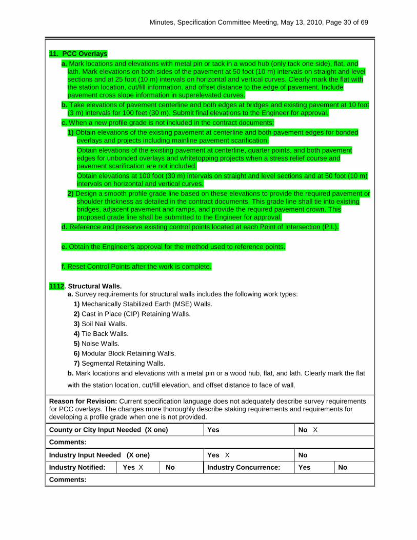
Add new Article 11: 11. PCC Overlays
a. Mark locations and elevations with metal pin or tack in a wood hub (only tack one side), flat, and lath. Mark elevations on both sides of the pavement at 50 foot (10 m) intervals on straight and level sections and at 25 foot (10 m) intervals on horizontal and vertical curves. Clearly mark the flat with the station location, cut/fill information, and offset distance to the edge of pavement. Include pavement cross slope information in superelevated curves.
b. Take elevations of pavement centerline and both edges at bridges and existing pavement at 10 foot (3 m) intervals for 100 feet (30 m). Submit final elevations to the Engineer for approval.
c. When a new profile grade is not included in the contract documents: 1) Obtain elevations of the existing pavement at centerline and both pavement edges for
bonded overlays and projects including mainline pavement scarification. 2) Obtain elevations of the existing pavement at centerline, quarter points, and both
pavement edges for unbonded overlays and whitetopping projects when a stress relief course and pavement scarification are not included.
3) Obtain elevations at 100 foot (30 m) intervals on straight and level sections and at 50 foot (10 m) intervals on horizontal and vertical curves.
4) Design a smooth profile grade line based on these elevations to provide the required pavement or shoulder thickness as detailed in the contract documents. This grade line shall tie into existing bridges, adjacent pavement and ramps, and provide the required pavement crown. This proposed grade line shall be submitted to the Engineer for approval.
d. Reference and preserve existing control points located at each Point of Intersection (P.I.). e. Obtain the Engineer’s approval for the method used to reference points. f. Reset Control Points after the work is complete.
Comments: SUDAS had some concerns with how this specification would apply to overlays done with stringless paving, in regards to the staking intervals. How to control overruns versus getting a smooth profile will need to be discussed. Some definitions in regard to bonded versus unbonded overlays will need to be reviewed. Since counties do a significant amount of bonded overlays, the counties and CP Tech Center will be asked for input before this revision is discussed in May.
Member’s Requested Change (Redline/Strikeout):
2526.03 SURVEY. 10. Pavement HMA Overlays (PCC and HMA)
a. Reference and preserve existing control points located at each Point of Intersection (P.I.). b. Obtain the Engineer’s approval for the method used to reference points. c. Reset Control Points after the work is complete.
Minutes, Specification Committee Meeting, May 13, 2010, Page 30 of 69
11. PCC Overlays
a. Mark locations and elevations with metal pin or tack in a wood hub (only tack one side), flat, and lath. Mark elevations on both sides of the pavement at 50 foot (10 m) intervals on straight and level sections and at 25 foot (10 m) intervals on horizontal and vertical curves. Clearly mark the flat with the station location, cut/fill information, and offset distance to the edge of pavement. Include pavement cross slope information in superelevated curves.
b. Take elevations of pavement centerline and both edges at bridges and existing pavement at 10 foot (3 m) intervals for 100 feet (30 m). Submit final elevations to the Engineer for approval.
c. When a new profile grade is not included in the contract documents: 1) Obtain elevations of the existing pavement at centerline and both pavement edges for bonded
overlays and projects including mainline pavement scarification. Obtain elevations of the existing pavement at centerline, quarter points, and both pavement edges for unbonded overlays and whitetopping projects when a stress relief course and pavement scarification are not included. Obtain elevations at 100 foot (30 m) intervals on straight and level sections and at 50 foot (10 m) intervals on horizontal and vertical curves.
2) Design a smooth profile grade line based on these elevations to provide the required pavement or shoulder thickness as detailed in the contract documents. This grade line shall tie into existing bridges, adjacent pavement and ramps, and provide the required pavement crown. This proposed grade line shall be submitted to the Engineer for approval.
d. Reference and preserve existing control points located at each Point of Intersection (P.I.). e. Obtain the Engineer’s approval for the method used to reference points. f. Reset Control Points after the work is complete.
1112. Structural Walls. a. Survey requirements for structural walls includes the following work types:
1) Mechanically Stabilized Earth (MSE) Walls. 2) Cast in Place (CIP) Retaining Walls. 3) Soil Nail Walls. 4) Tie Back Walls. 5) Noise Walls. 6) Modular Block Retaining Walls. 7) Segmental Retaining Walls.
b. Mark locations and elevations with a metal pin or a wood hub, flat, and lath. Clearly mark the flat
with the station location, cut/fill elevation, and offset distance to face of wall.
Reason for Revision: Current specification language does not adequately describe survey requirements for PCC overlays. The changes more thoroughly describe staking requirements and requirements for developing a profile grade when one is not provided.
County or City Input Needed (X one) Yes No X
Comments:
Industry Input Needed (X one) Yes X No
Industry Notified: Yes X No Industry Concurrence: Yes No
Comments:

Minutes, Specification Committee Meeting, May 13, 2010, Page 31 of 69
SPECIFICATION REVISION SUBMITTAL FORM Submitted by: Deanna Maifield Office: Design Item 16
Submittal Date: 4/30/2010 Proposed Effective Date: 10/19/2010
Article No.: 2529.02, E Title: Subbase Article No.: 2529.03, C, 1 Title: General Article No.: 2529.03, D, 2 Title: Restoring Subbase or Subgrade for Full Depth Finish Patches
Other:
Specification Committee Action: Approved as is.
Deferred: Not Approved: Approved Date: 5/13/2010 Effective Date: 10/19/2010
Specification Committee Approved Text: See Specification Section Recommended Text.
Comments: Modified subbase material will offer more stability under full depth patches.
Specification Section Recommended Text: 2529.02, E, Subbase.
Rename and Replace the article: E. Subbase Patch Material.
Meet the requirements of Section 4121 4123. 2529.03, C, 1, a.
Replace the second sentence of the Article: Excavation will be required for the patch thickness and, if required, for the granular subbase patch material.
2529.03, C, 1, b.
Replace the third bulleted item of the Article: • Replace the concrete with granular subbase aggregate patch material, compacted as
required, to the elevation of the bottom of the patch. 2529.03, D, 2.
Replace the second and third sentences of the Article: Overdepth removal may be replaced with granular subbase patch material or the patching mixture. When the granular subbase patch material cannot be properly drained, replace the overdepth removal with the patching mixture.
Comments:
Member’s Requested Change: (Do not use ‘Track Changes’, or ‘Mark-Up’. Use Strikeout and Highlight.) 2529.02, E, Subbase.
Replace the title and article:
Subbase Patch Material. Meet the requirements of Section 41213.
2529.03, C, 1, General.
Replace “granular subbase” with “subbase patch material” in the second sentence of Paragraph a.

Minutes, Specification Committee Meeting, May 13, 2010, Page 32 of 69
Replace “granular subbase aggregate” with “subbase patch material” in the third bulleted item of Paragraph b.
2529.03, D, 2, Restoring Subbase or Subgrade for Full Depth Finish Patches.
Replace “granular subbase material” with “subbase patch material” in the second and third sentences.
Reason for Revision: Changing subbase patch material to modified subbase.
County or City Input Needed (X one) Yes No X
Comments:
Industry Input Needed (X one) Yes No X
Industry Notified: Yes No X Industry Concurrence: Yes No
Comments:

Minutes, Specification Committee Meeting, May 13, 2010, Page 33 of 69
SPECIFICATION REVISION SUBMITTAL FORM Submitted by: Deanna Maifield Office: Design Item 17
Submittal Date: 2010.03.10 Proposed Effective Date: 10/2010
Section No.: 2548 Title: Milled Shoulder Rumble Strips
Other:
Specification Committee Action: Not approved at this time.
Deferred: Not Approved: X Approved Date: Effective Date:
Specification Committee Approved Text:
Comments: The Office of Construction questioned the method of measurement for milled rumble strips. Language will be changed from “measured” to “calculated” to indicate that these items would be plan quantity, minus any deductions for degraded pavement or unsatisfactory test strips. The Office of Construction asked if the centerline rumble strips could be done as part of a district wide project each year. This would allow better timing of the fog seal. The Office of Materials asked if we should be using rapid set emulsion for fog sealing rumble strips. The rapid set emulsion would allow placing pavement markings sooner. The Office of Materials indicated that a rapid set emulsion is not compatible with the proposed use of Gilsonite. Following the Specification Committee meeting, a meeting was held to discuss some of the construction and materials issues related to centerline rumble strips. It was decided that the Iowa DOT is not ready to include centerline rumble strips as a part of the Standard Specifications. A DS will be developed including the use of Gilsonite for use until centerline rumble strips can be added to the Standard Specifications. The DS will be submitted to the Specification Committee when it is ready for approval, but it is intended to have this ready for use by the October 2010 letting. The Office of Materials will work with the Research and Technology Bureau on a research project for this summer to evaluate the constructability and materials for centerline rumble strips.
Specification Section Recommended Text: 2548, Milled Shoulder Rumble Strips – HMA or PCC Surface
Retitle the Section: Section 2548. Milled Shoulder Rumble Strips – HMA or PCC Surface
2548.01, General.
Replace the Article: Provide equipment, furnish all necessary labor and materials, and perform all operations necessary for milling shoulder rumble strips in HMA or PCC surfaced shoulders surfaces. Mill shoulder rumble strips to the dimensions and spacing shown in the contract documents. Apply diluted asphalt emulsion to the milled shoulder rumble strips on HMA surfaced shoulders surfaces by means of a bituminous distributor.
2548.02, B, 2.
Replace the first sentence of the Article: Dilute the asphalt emulsion with water prior to application to the milled shoulder rumble strip.
2548.03, Construction.
Replace the first paragraph: Notify the Engineer if degraded shoulders are pavement is encountered that will not accommodate milled rumble strips. Skip those sections.
2548.03, A, Test Strip.
Replace the first sentence: Demonstrate to the Engineer on an initial 500 foot (150 m) test section that the equipment and method will provide the desired milled shoulder rumble strip and surface inside each depression without damaging

Minutes, Specification Committee Meeting, May 13, 2010, Page 34 of 69
the adjacent pavement. 2548.03, B, 1.
Delete the third sentence of the Article: The offset may be decreased to 6 inches (150 mm) on shoulders with a top width less than 30 inches (750 mm).
2548.03, B, Milling.
Renumber Article 2 to Article 3. Add new Article 2:
2. Mill centerline rumble strips in a straight line, on the centerline joint as shown in the contract documents. Do not deviate more than ±1 inch (25 mm) from the intended location. Ensure the depth of the rumble strips is as shown in the contract documents. The Engineer will randomly check the alignment and depth.
2548.03, C, 2.
Replace the Article: Ensure the application width covers the entire milled shoulder rumble strip.
2548.04, A, Milled Shoulder Rumble Strips.
Replace the Article: Stations (meters) shown in the contract documents, measured along each edge of mainline pavement abutting a paved shoulder. Unless stated otherwise in the contract documents, no deduction will be made for gapped areas. The quantity will be adjusted for the length of degraded shoulders pavement skipped, as defined in Article 2548.03 of this specification. The quantity will be adjusted for test sections that were deemed unsatisfactory.
2548.04, Method of Measurement.
Renumber and Rename Article B: B C. Asphalt Emulsion for Fog Seal (For Milled Rumble Strips).
Add new Article B:
B. Milled Centerline Rumble Strips. Stations (meters) shown in the contract documents, measured along the centerline of mainline pavement. Unless stated otherwise in the contract documents, no deduction will be made for gapped areas. The quantity will be adjusted for the length of degraded pavement skipped, as defined in Article 2548.03. The quantity will be adjusted for test sections that were deemed unsatisfactory.
2548.05, Basis of Payment.
Renumber and Rename Article B: B C. Asphalt Emulsion for Fog Seal (For Milled Rumble Strips).
Add new Article B:
B. Milled Centerline Rumble Strips. Per station (meter) for the type specified.
Comments: The Office of Bridges and Structures asked about the statement “no deduction will be made for gapped areas”. Gapped areas include gaps at bridges, sideroads, etc. Some designers have been taking the gapped areas out of the quantity. The Office of Construction would like to include these gaps in the measurement for ease of inspection and design. The Office of Construction expressed some reservations about the effect of the centerline rumble strips on the condition of the centerline. This is especially relevant when the notched centerline joint is used.
Minutes, Specification Committee Meeting, May 13, 2010, Page 35 of 69
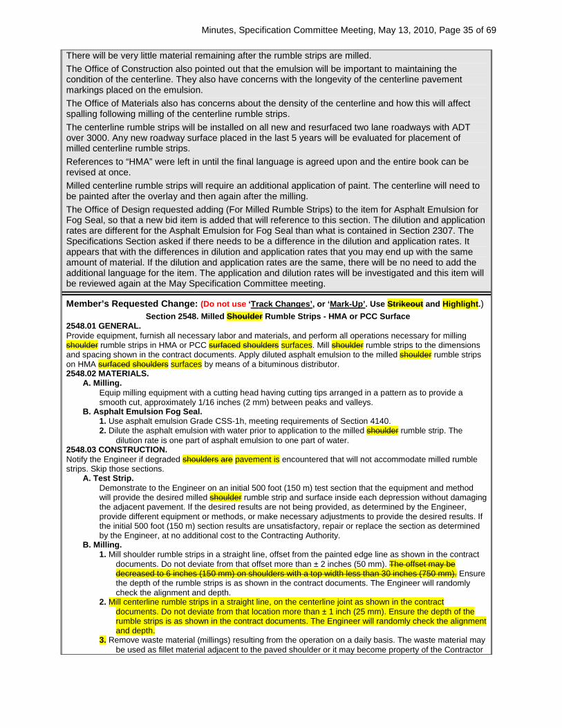
There will be very little material remaining after the rumble strips are milled. The Office of Construction also pointed out that the emulsion will be important to maintaining the condition of the centerline. They also have concerns with the longevity of the centerline pavement markings placed on the emulsion. The Office of Materials also has concerns about the density of the centerline and how this will affect spalling following milling of the centerline rumble strips. The centerline rumble strips will be installed on all new and resurfaced two lane roadways with ADT over 3000. Any new roadway surface placed in the last 5 years will be evaluated for placement of milled centerline rumble strips. References to “HMA” were left in until the final language is agreed upon and the entire book can be revised at once. Milled centerline rumble strips will require an additional application of paint. The centerline will need to be painted after the overlay and then again after the milling. The Office of Design requested adding (For Milled Rumble Strips) to the item for Asphalt Emulsion for Fog Seal, so that a new bid item is added that will reference to this section. The dilution and application rates are different for the Asphalt Emulsion for Fog Seal than what is contained in Section 2307. The Specifications Section asked if there needs to be a difference in the dilution and application rates. It appears that with the differences in dilution and application rates that you may end up with the same amount of material. If the dilution and application rates are the same, there will be no need to add the additional language for the item. The application and dilution rates will be investigated and this item will be reviewed again at the May Specification Committee meeting.
Member’s Requested Change: (Do not use ‘Track Changes’, or ‘Mark-Up’. Use Strikeout and Highlight.) Section 2548. Milled Shoulder Rumble Strips - HMA or PCC Surface
2548.01 GENERAL. Provide equipment, furnish all necessary labor and materials, and perform all operations necessary for milling shoulder rumble strips in HMA or PCC surfaced shoulders surfaces. Mill shoulder rumble strips to the dimensions and spacing shown in the contract documents. Apply diluted asphalt emulsion to the milled shoulder rumble strips on HMA surfaced shoulders surfaces by means of a bituminous distributor. 2548.02 MATERIALS.
A. Milling. Equip milling equipment with a cutting head having cutting tips arranged in a pattern as to provide a smooth cut, approximately 1/16 inches (2 mm) between peaks and valleys.
B. Asphalt Emulsion Fog Seal. 1. Use asphalt emulsion Grade CSS-1h, meeting requirements of Section 4140. 2. Dilute the asphalt emulsion with water prior to application to the milled shoulder rumble strip. The
dilution rate is one part of asphalt emulsion to one part of water. 2548.03 CONSTRUCTION. Notify the Engineer if degraded shoulders are pavement is encountered that will not accommodate milled rumble strips. Skip those sections.
A. Test Strip. Demonstrate to the Engineer on an initial 500 foot (150 m) test section that the equipment and method will provide the desired milled shoulder rumble strip and surface inside each depression without damaging the adjacent pavement. If the desired results are not being provided, as determined by the Engineer, provide different equipment or methods, or make necessary adjustments to provide the desired results. If the initial 500 foot (150 m) section results are unsatisfactory, repair or replace the section as determined by the Engineer, at no additional cost to the Contracting Authority.
B. Milling. 1. Mill shoulder rumble strips in a straight line, offset from the painted edge line as shown in the contract
documents. Do not deviate from that offset more than ± 2 inches (50 mm). The offset may be decreased to 6 inches (150 mm) on shoulders with a top width less than 30 inches (750 mm). Ensure the depth of the rumble strips is as shown in the contract documents. The Engineer will randomly check the alignment and depth.
2. Mill centerline rumble strips in a straight line, on the centerline joint as shown in the contract documents. Do not deviate from that location more than ± 1 inch (25 mm). Ensure the depth of the rumble strips is as shown in the contract documents. The Engineer will randomly check the alignment and depth.
3. Remove waste material (millings) resulting from the operation on a daily basis. The waste material may be used as fillet material adjacent to the paved shoulder or it may become property of the Contractor

Minutes, Specification Committee Meeting, May 13, 2010, Page 36 of 69
and disposed of off the project. Disposal of material may be at an approved landfill or approved stockpile, or by other methods that will allow the material to be recycled. Remove waste material prior to opening adjacent lane to traffic.
C. Asphalt Emulsion Fog Seal. 1. Ensure the equipment meets the requirements of Section 2001. 2. Ensure the application width covers the entire milled shoulder rumble strip. 3. Place the diluted asphalt emulsion fog seal according to Article 2308.03, D, at a rate of 0.13 gallon per
square yard (0.6 L/m2). 4. Do not place asphalt emulsion on a damp or wet surface. 5. Apply asphalt emulsion during weather conditions under which satisfactory application can be obtained.
Do not apply asphalt emulsion when the air temperature is below 50°F (10°C). Do not place asphalt emulsion after October 15 without the Engineer’s permission.
D. Limitations. Do not disturb desirable grass areas and desirable trees outside the construction limits. Do not park or service vehicles and equipment or use these areas for storage of materials. Obtain the Engineer’s approval for storage, parking, and service areas.
2548.04 METHOD OF MEASUREMENT. Measurement will be as follows:
A. Milled Shoulder Rumble Strips. Stations (meters) shown in the contract documents, measured along each edge of mainline pavement abutting a paved shoulder. Unless stated otherwise in the contract documents, no deduction will be made for gapped areas. The quantity will be adjusted for the length of degraded shoulders pavement skipped, as defined in Article 2548.03 of this specification. The quantity will be adjusted for test sections that were deemed unsatisfactory.
B. Milled Centerline Rumble Strips. Stations (meters) shown in the contract documents, measured along the centerline of mainline pavement. Unless stated otherwise in the contract documents, no deduction will be made for gapped areas. The quantity will be adjusted for the length of degraded pavement skipped, as defined in Article 2548.03 of this specification. The quantity will be adjusted for test sections that were deemed unsatisfactory.
C. Asphalt Emulsion for Fog Seal. Gallons (liters) as provided in Article 2307.04, B.
2548.05 BASIS OF PAYMENT. Payment will be the contract unit price as follows:
A. Milled Shoulder Rumble Strips. Per station (meter) for the type specified.
B. Milled Centerline Rumble Strips. Per station (meter) for the type specified.
C. Asphalt Emulsion for Fog Seal. 1. Per gallon (liter) for undiluted Asphalt Emulsion for Fog Seal that is mixed and used on the project.
Diluted asphalt emulsion that is delivered to the project site, but not applied to the roadway surface will not be considered for payment.
2. Payment is full compensation for cleaning the shoulder paved surface, furnishing and applying diluted asphalt emulsion, mixing water, and protecting the adjacent pavement and edge lines.
Reason for Revision: Centerline rumble strips will be added to projects and there is no current spec. Also, the note in 2548.03B that allows reduction to 6” offset is out of date because we now use a 6” offset everywhere. County or City Input Needed (X one) Yes No x Comments: Industry Input Needed (X one) Yes No x Industry Notified: Yes No x Industry Concurrence: Yes No Comments:
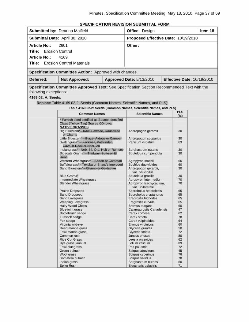
Minutes, Specification Committee Meeting, May 13, 2010, Page 37 of 69
SPECIFICATION REVISION SUBMITTAL FORM Submitted by: Deanna Maifield Office: Design Item 18
Submittal Date: April 30, 2010 Proposed Effective Date: 10/19/2010
Article No.: 2601 Title: Erosion Control Article No.: 4169 Title: Erosion Control Materials
Other:
Specification Committee Action: Approved with changes.
Deferred: Not Approved: Approved Date: 5/13/2010 Effective Date: 10/19/2010
Specification Committee Approved Text: See Specification Section Recommended Text with the following exceptions: 4169.02, A, Seeds.
Replace Table 4169.02-2: Seeds (Common Names, Scientific Names, and PLS): Table 4169.02-2: Seeds (Common Names, Scientific Names, and PLS)
Common Names Scientific Names PLS (%)
* Furnish seed certified as Source Identified Class (Yellow Tag) Source G0-Iowa.
Big Bluestem* - Kaw, Pawnee, Roundtree NATIVE GRASSES
or Champ Little Bluestem* - Blaze, Aldous or Camper Switchgrass* - Blackwell, Pathfinder,
Cave-in-Rock or Nebr. 28 Indiangrass* - Neb. 54, Oto, Holt or Rumsey Sideoats Grama* - Trailway, Butte or El Reno Western Wheatgrass* - Barton or Common Buffalograss* - Texoka or Sharp's Improved Sand Bluestem* - Champ or Goldstrike Blue Grama* Intermediate Wheatgrass Slender Wheatgrass Prairie Dropseed Sand Dropseed Sand Lovegrass Weeping Lovegrass Hairy Wood Chess Blue-joint grass Bottlebrush sedge Tussock sedge Fox sedge Virginia wild-rye Reed manna grass Fowl manna grass Common rush Rice Cut Grass Rye grass, annual Fowl bluegrass Green bulrush Wool grass Soft-stem bulrush Indian grass Spike Rush
Andropogon gerardii Andropogon scoparius Panicum virgatum Sorghastrum nutans Bouteloua curtipendula Agropyron smithii Buchloe dactyloides Andropogon gerardii,
var. paucipilus Bouteloua gracilis Agropyron intermedium Agropyron trachycaulum,
var. unilaterale Sporobolus heterolepis Sporobolus cryptandrus Eragrostis trichodes Eragrostis curvula Bromus purgans Calamagrostis Canadensis Carex comosa Carex stricta Carex vulpinoidea Elymus virginicus Glyceria grandis Glyceria striata Juncus effuses Leesia oryzoides Lolium italicum Poa palustris Scirpus atrovirens Scirpus cyperinus Scirpus vallidus Sorghastrum nutans Eleocharis palustris
30
30 63
30 30
56 60 30
30 70 70
65 65 65 65 60 47 62 78 64 60 50 72 80 62 89 72 45 78 78 60 71

Minutes, Specification Committee Meeting, May 13, 2010, Page 38 of 69
Canada anemone FORBS
Marsh milkweed New England aster Swamp aster Showy tic-trefoil Joe-pye weed Boneset Ox Eye sunflower Blue-flag iris Meadow blazingstar Tall blazingstar Great blue lobelia Reed manna grass Fowl manna grass Common Rush Rice Cut Grass
Anemone Canadensis Asclepias incarnate Aster novae-angliae Aster puniceus Desmodium canadense Eupatorium maculatum Eupatorium perfoliatum Heliopsis helianthoides Iris virginica-shrevii Liatris ligulistylis Liatris pycnostachya Lobelia siphilitica Glyceria grandis Glyceria striata Juncus effuses Leesia oryzoides
72 25 25 25 25 66 41 38 19 24 24 13 50 72 80 62
Comments: There was an error in the recommended text for the Table 4169.02-2: Seeds. The correct version is shown in the approved text. The committee decided that standard seed mixes as specified in the spec. book should not be repeated on the plan. Only when there is a change in the seed mix will we show it on the plan. This may be something that contractors and seed suppliers need to get used to, but this method is consistent with Iowa DOT practice. The Committee recommended adding the yellow tag, Iowa origin note from Table 2601.03-3 to Section 4169 so we always require the yellow tag, Iowa origin seed for native grasses. The Office of Design will write a Public Interest Finding memo to justify the use of Iowa origin seed. The Office of Design explained that the Engineer will no longer need to witness mixing of our urban and rural seed mixtures (actually all seed mixtures except native grass, wildflower and wetland). This reduces inspection requirements and should result in some cost saving since the seed suppliers will be able to mix theses seed mixtures in bulk for future projects. Overseeding and sodding dates have also been changed.
Specification Section Recommended Text: 2601.02, B.
Replace the second sentence and Delete the third sentence: Apply seeds for native grasses, wildflower and wetland grass seeding on a PLS basis, as computed by the Engineer. For native grasses identified in Article 4169.02 with both purity and germination requirements, adjust application rates for grasses that exceed these minimum requirements to an equivalent computed on a PLS basis.
2601.03, A, Equipment.
Renumber Articles 12 through 17 as Articles13 through 18. Add new Article 12:
12. Pneumatic Seeder. Use a pneumatic (air blower) system with enough power and hose to reach 300 feet (100 m).
2601.03, B, 4, c, 1.
Replace Table 2601.03-1: Permanent Seed Mixture, Rural Areas: Table 2601.03-1: Permanent Seed Mixture, Rural Areas
Fescue, Fawn Ryegrass, (Perennial) Sideoats Grama (Butte or Trailway) Switchgrass (Neb. 28, Blackwell, Pathfinder, or Cave-In-Rock) Birdsfoot Trefoil (Empire)
25 55 lbs. per acre (28 62 kg/ha) 15 45 lbs. per acre (17 51 kg/ha) 5 lbs PLS per acre (6 kg PLS/ha) 3lbs. PLS per acre (3 kg PLS/ha) 5 lbs. per acre (5 6 kg/ha)
2601.03, B, 4, e, 1.
Replace the second sentence:

Minutes, Specification Committee Meeting, May 13, 2010, Page 39 of 69
Ensure the Engineer witnesses all seed mixing for Native Grass, Wildflower and Wetland Grass seeding mixtures.
2601.03, B, 4, l, 1. Replace the Article:
Seedbed preparation will not be required, provided the overseeding is applied when the ground is friable from frost action after March 1 February 1 and before April 1 or as directed by the Engineer.
2601.03, G, 3, c, 1.
Replace the Article: Do not place sod between May 31 and August 10 September 1, or on frozen ground unless otherwise directed by the Engineer.
2601.05, A, 8, b.
Replace the second sentence: This includes reshaping intercepting ditches and flumes, seed, fertilizer, stapling, mulch, and in areas where special ditch control is specified, for construction of intercepting ditches and flumes seedbed preparation, seed and fertilizer, special ditch control (wood excelsior mat), stapling and installation of materials.
4169.02, A, Seeds. Replace Table 4169.02-2: Seeds (Common Names, Scientific Names, and PLS):
Table 4169.02-2: Seeds (Common Names, Scientific Names, and PLS)
Common Names Scientific Names PLS (%)
Big Bluestem - Kaw, Pawnee, Roundtree NATIVE GRASSES
or Champ Little Bluestem - Blaze, Aldous or Camper Switchgrass - Blackwell, Pathfinder,
Cave-in-Rock or Nebr. 28 Indiangrass - Neb. 54, Oto, Holt or Rumsey Sideoats Grama - Trailway, Butte or El Reno Western Wheatgrass - Barton or Common Buffalograss - Texoka or Sharp's Improved Sand Bluestem - Champ or Goldstrike Blue Grama Intermediate Wheatgrass Slender Wheatgrass Prairie Dropseed Sand Dropseed Sand Lovegrass Weeping Lovegrass Hairy Wood Chess Blue-joint grass Bottlebrush sedge Tussock sedge Fox sedge Virginia wild-rye Reed manna grass Fowl manna grass Common rush Rice Cut Grass Rye grass, annual Fowl bluegrass Green bulrush Wool grass Soft-stem bulrush Indian grass Spike Rush
Andropogon gerardii Andropogon scoparius Panicum virgatum Sorghastrum nutans Bouteloua curtipendula Agropyron smithii Buchloe dactyloides Andropogon gerardii,
var. paucipilus Bouteloua gracilis Agropyron intermedium Agropyron trachycaulum,
var. unilaterale Sporobolus heterolepis Sporobolus cryptandrus Eragrostis trichodes Eragrostis curvula Bromus purgans Calamagrostis Canadensis Carex comosa Carex stricta Carex vulpinoidea Elymus virginicus Glyceria grandis Glyceria striata Juncus effuses Leesia oryzoides Lolium italicum Poa palustris Scirpus atrovirens Scirpus cyperinus Scirpus vallidus Sorghastrum nutans Eleocharis palustris
30
30 63
30 30 56 60 30
30 70 70
65 65 65 65 60 47 62 78 64 60 50 72 80 62 89 72 45 78 78 60 71

Minutes, Specification Committee Meeting, May 13, 2010, Page 40 of 69
Canada anemone FORBS
Marsh milkweed New England aster Swamp aster Showy tic-trefoil Joe-pye weed Boneset Ox Eye sunflower Blue-flag iris Meadow blazingstar Tall blazingstar Great blue lobelia Reed manna grass Fowl manna grass Common Rush Rice Cut Grass
Anemone Canadensis Asclepias incarnate Aster novae-angliae Aster puniceus Desmodium canadense Eupatorium maculatum Eupatorium perfoliatum Heliopsis helianthoides Iris virginica-shrevii Liatris ligulistylis Liatris pycnostachya Lobelia siphilitica Glyceria grandis Glyceria striata Juncus effuses Leesia oryzoides
72 25 25 25 25 66 41 38 19 24 24 13 50 72 80 62
4169.02, D.
Delete the Article. D. If the purity and/or germination of native grasses exceeds the minimum required, the application rate
may be adjusted, based on PLS. 4169.07, A, Straw Mulch.
Replace the second sentence: Use material free from noxious weeds Certified Noxious Weed Seed Free Mulch certified by the Iowa Crop Improvement Association or other state’s Crop Improvement Associations.
Comments:
Member’s Requested Change: (Do not use ‘Track Changes’, or ‘Mark-Up’. Use Strikeout and Highlight.) 2601.02, B, Materials.
Replace the second sentence: Apply seeds for native grasses on a PLS basis, as computed by the Engineer. Apply seed for native grass, wildflower and wetland seeding on a PLS basis as computed by the Engineer.
Delete the third sentence:
For native grasses identified in Article 4169.02 with both purity and germination requirements, adjust application rates for grasses that exceed these minimum requirements to an equivalent computed on a PLS basis.
2601.03, A, Equipment.
Add as Paragraph 12: Pneumatic Seeder. Use a pneumatic (air blower) system with enough power and hose to reach 300 feet (100 m).
Renumber Paragraphs 12 through 17 as Paragraphs 13 through 18.
2601.03, B, 4, c, 1, Application of Seed. Table 2601.03-1: Permanent Seed Mixture, Rural Areas. Replace existing table: Fescue, Fawn 55 lbs per acre (62 kg/ha) Ryegrass, Perennial 45 lbs per acre (51 kg/ha) Birdsfoot Trefoil 5 lbs per acre (61 kg/ha)

Minutes, Specification Committee Meeting, May 13, 2010, Page 41 of 69
2601.03, B, 4, e, 1, Preparation of Seed. Replace the second sentence:
Ensure the Engineer witnesses all seed mixing for Native Grass and Wildflower seed mixtures and Wetland Grass Seeding seed mixtures.
2601.03, G, 3, c, 1, Placing Sod. Replace August 10 with September 1.
2601.03 B, 4, l, 1, Spring Overseeding. Replace March 1 with February 1.
2601.03 G, 3, d, 4, Finishing Sod.
Replace “Article 2106.03, F, 3, e” with “Article 2106.03, G, 3, e”. 2601.05, A, 8, b, Basis of Payment.
Replace the second sentence: This includes reshaping intercepting ditches and flumes, seed, fertilizer, stapling, mulch, and in areas where special ditch control is specified, for construction of intercepting ditches and flumes seedbed preparation, seed and fertilizer, special ditch control (wood excelsior mat), stapling and installation of materials.
4169.02, A, Seeds. Remove the following varieties from Table 4169.02-2:
Big Bluestem, Little Bluestem, Switchgrass, Indiangrass, Sideoats Grama, Western Wheatgrass, Buffalograss, and Sand Bluestem.
4169.02, D, Seeds. Delete the Article.
4169.02, E, Seeds. Renumber as Article D.
4169.02, F, Seeds.
Renumber as Article E. 4169.07, A, Straw Mulch.
Replace the second sentence: Use material free from noxious weeds Certified Noxious Weed Seed Free Mulch certified by the Iowa Crop Improvement Association or other state’s Crop Improvement Associations.
Reason for Revision: 1.) Add new equipment. 2.) Update seed mixtures. 3.) Update seeding and sodding dates. 4.) Update mulch requirements. 5.) Update procedures and methodology.
County or City Input Needed (X one) Yes No
Comments:

Minutes, Specification Committee Meeting, May 13, 2010, Page 42 of 69
Industry Input Needed (X one) Yes No
Industry Notified: Yes No Industry Concurrence: Yes No
Comments:

Minutes, Specification Committee Meeting, May 13, 2010, Page 43 of 69
SPECIFICATION REVISION SUBMITTAL FORM Submitted by: Jim Berger Office: Materials Item 19
Submittal Date: 4-28-10 Proposed Effective Date: October 2010
Section No.: 4105 Title: Liquid Curing Compounds.
Other:
Specification Committee Action: Approved as is.
Deferred: Not Approved: Approved Date: 5/13/2010 Effective Date: 10/19/2010
Specification Committee Approved Text: See Specification Section Recommended Text.
Comments: None. Specification Section Recommended Text: 4105.03, MOISTURE RETENTION.
Replace the Article: Efficiency index of the material shall not be less than 95.0% when tested according to Office of Materials Test Method No. Iowa 901. Material showing moisture loss of less than 1% of the quantity of water remaining in the test specimen at the time the curing material is applied will also be acceptable. White pigmented liquid curing compounds, when tested in accordance with ASTM C 156 using an application rate of 200 square feet per gallon (5 m2/L) shall restrict the loss of water to not more than 0.20 kg/m2 in 24 hours or 0.40 kg/m2 in 72 hours.
4105.05, WHITE PIGMENTED COMPOUNDS.
Delete Article D: D. Use an application rate of no less than 0.067 gallon per square yard (0.3 L/m2) (15 square
yards per gallon (3.3 m2/L)). Comments:
Member’s Requested Change: (Do not use ‘Track Changes’, or ‘Mark-Up’. Use Strikeout and Highlight.) 4105.03 Moisture Retention. Efficiency index of the material shall not be less than 95.0% when tested according to Office of Materials Test Method No. Iowa 901. Material showing moisture loss of less than 1% of the quantity of water remaining in the test specimen at the time the curing material is applied will also be acceptable. White pigmented liquid curing compounds, when tested in accordance with ASTM test method C 156 using an application rate of 200sq.ft/Gal (5sq.m/L) shall restrict the loss of water to not more than 0.20 Kg/sq.m in 24 hours or 0.40 Kg/sq.m in 72 hours. 4105.05 D. Use an application rate of no less than 0.067 gallon per square yard(0.3 L/m2) (15 square yards per gallon (3.3 m2/L)). E D.
Reason for Revision: To make the acceptance test procedure in line with national standards. County or City Input Needed (X one) Yes No X
Comments:
Industry Input Needed (X one) Yes No X
Industry Notified: Yes X No Industry Concurrence: Yes X No
Comments:
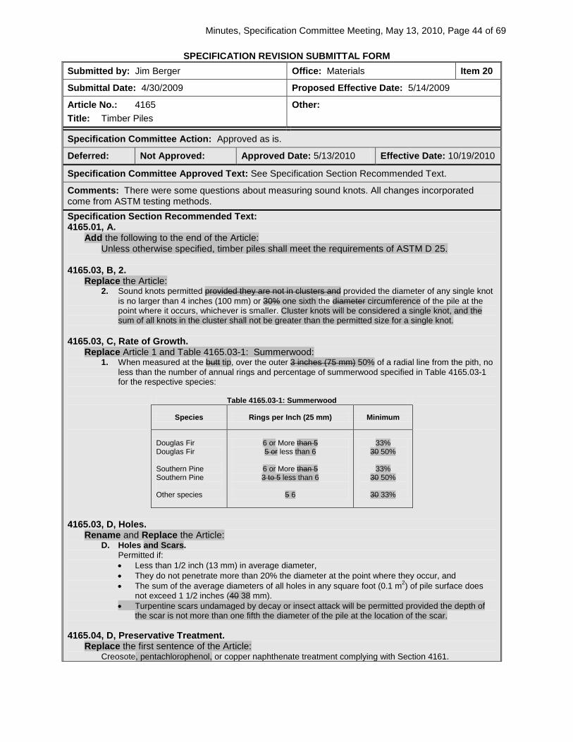
Minutes, Specification Committee Meeting, May 13, 2010, Page 44 of 69
SPECIFICATION REVISION SUBMITTAL FORM Submitted by: Jim Berger Office: Materials Item 20
Submittal Date: 4/30/2009 Proposed Effective Date: 5/14/2009
Article No.: 4165 Title: Timber Piles
Other:
Specification Committee Action: Approved as is.
Deferred: Not Approved: Approved Date: 5/13/2010 Effective Date: 10/19/2010
Specification Committee Approved Text: See Specification Section Recommended Text.
Comments: There were some questions about measuring sound knots. All changes incorporated come from ASTM testing methods. Specification Section Recommended Text: 4165.01, A.
Add the following to the end of the Article: Unless otherwise specified, timber piles shall meet the requirements of ASTM D 25.
4165.03, B, 2.
Replace the Article: 2. Sound knots permitted provided they are not in clusters and provided the diameter of any single knot
is no larger than 4 inches (100 mm) or 30% one sixth the diameter circumference of the pile at the point where it occurs, whichever is smaller. Cluster knots will be considered a single knot, and the sum of all knots in the cluster shall not be greater than the permitted size for a single knot.
4165.03, C, Rate of Growth.
Replace Article 1 and Table 4165.03-1: Summerwood: 1. When measured at the butt tip, over the outer 3 inches (75 mm) 50% of a radial line from the pith, no
less than the number of annual rings and percentage of summerwood specified in Table 4165.03-1 for the respective species:
Table 4165.03-1: Summerwood
Species Rings per Inch (25 mm) Minimum
Douglas Fir Douglas Fir Southern Pine Southern Pine Other species
6 or More than 5 5 or less than 6
6 or More than 5 3 to 5 less than 6
5 6
33% 30 50%
33%
30 50%
30 33%
4165.03, D, Holes.
Rename and Replace the Article: D. Holes and Scars.
Permitted if: • Less than 1/2 inch (13 mm) in average diameter, • They do not penetrate more than 20% the diameter at the point where they occur, and • The sum of the average diameters of all holes in any square foot (0.1 m2) of pile surface does
not exceed 1 1/2 inches (40 38 mm). • Turpentine scars undamaged by decay or insect attack will be permitted provided the depth of
the scar is not more than one fifth the diameter of the pile at the location of the scar. 4165.04, D, Preservative Treatment.
Replace the first sentence of the Article: Creosote, pentachlorophenol, or copper naphthenate treatment complying with Section 4161.

Minutes, Specification Committee Meeting, May 13, 2010, Page 45 of 69
Comments:
Member’s Requested Change: (Do not use ‘Track Changes’, or ‘Mark-Up’. Use Strikeout and Highlight.)
Section 4165. Timber Piles.
4165.01 DESCRIPTION. Timber piles shall be round sections of the trunks of trees trimmed, peeled, and with or without preservative treatment. They shall meet the requirements for the class of piles specified in the contract documents. Unless otherwise specified, timber piles shall meet the requirements of ASTM D25.
Inspection arrangements shall be in accordance with Materials I.M. 462. The cost of inspection shall be included in the unit price bid for the material specified.
4165.02 CLASSIFICATION. Piles shall be classified as follows, according to the use for which they are intended:
A. Untreated Timber Piles. Untreated timber piles may be used for falsework or temporary construction.
B. Treated Timber Foundation Piles. Treated timber foundation piles will be used for permanent foundations and for permanent wood substructures above ground water level, unless treated timber trestle piles are specified in the contract documents.
C. Treated Timber Trestle Piles. Treated timber trestle piles shall be used for permanent wood trestle and may be specified for piers and abutments of substructures, where the more restrictive straightness requirements of this class are desirable.
4165.03 UNTREATED TIMBER PILES. Timber piles to be used where preservative treatment is not required may be White Oak, Burr Oak, Cypress, Tamarack, Douglas Fir, Southern Pine, or other wood which will satisfactorily withstand driving. They shall meet the following requirements:
A. General Quality. Piles shall be cut above the ground swell from live, sound, solid trees and shall have a gradual taper from point of butt measurement to tip. They shall be free from ring shakes, decay or rot, unsound knots, soft red heart, splits, and other defects which will impair their strength or durability. Cypress piles showing "peck" more than a single spot equal to 3% of the area of the end will not be accepted. Piles shall be free from excessive checks at the tip which would cause splits in driving.
B. Knots. Piles shall have no unsound knots. Sound knots will be permitted, provided they are not in clusters, and provided the diameter of any single knot is not larger than 4 inches (100 mm) or 30% one sixth of the diameter circumference of the pile at the point where it occurs, whichever is smaller. Cluster knots shall be considered as a single knot, and the sum of all knots in the cluster shall not be greater than the permitted size for a single knot. The sum of diameters of all knots in any 1 foot (0.3 m) length of pile shall not exceed 2 times the diameter of the allowable knot. Diameters of knots shall be measured in a plane perpendicular to the long axis of the pile.
C. Rate of Growth. When measured at the butt tip, over the outer 3 inches (75 mm) 50% of a radial line from the pith, piles shall show not less than the number of annual rings and percentage of summerwood specified below for the respective species:

Minutes, Specification Committee Meeting, May 13, 2010, Page 46 of 69
SUMMERWOOD
Species Rings per Inch (25 mm) Minimum
Douglas Fir Douglas Fir Southern Pine Southern Pine Other species
6 or Mmore than 5 5 or less than 6
6 or Mmore than 5 3 to 5 less than 6
5 6
33% 3050% 33%
3050% 3033%
When the number of annual rings varies along different radii, the average of two or more measurements along representative radii shall be used.
D. Holes and Scars. Holes shall be permitted if less than 1/2 inch (13 mm) in average diameter, if they do not penetrate more than 20% the diameter at the point where they occur, and if the sum of the average diameters of all holes in any square foot (0.1 m2) of pile surface does not exceed 1 1/2 inches (3840 mm). Turpentine scars undamaged by decay or insect attack shall be permitted provided the depth of the scar is not more than one fifth of the diameter of the pile at the location of the scar.
E. Twist of Grain. Piles shall be free of twist in grain exceeding 50% the average circumference in a 20 foot (6 m) length.
F. Length. Piles shall be furnished in the length specified in the contract documents or as directed by the Engineer. A variation of 6 inches (150 mm) in length will be permitted, but the average length for piles of any one lot shall be at least equal to the specified length.
G. Straightness. Piles shall be free from sweep in two planes (double sweep). They shall be free of short crooks. In measuring for short crooks in any 5 foot (1.5 m) section, the distance from the center of the pile at the point of greatest deviation to a line stretched from the center of the pile above the bend to the center of the pile below the bend shall not exceed 4% of the length of the bend, or a maximum of 2 1/2 inches (65 mm). In sweep in one direction and in one plane, the center of the pile shall not deviate from a straight line connecting the center of butt with the center of the tip by more than 1.0% of the length of the pile, or 4 inches (100 mm), whichever is greater, with a maximum deviation of 6 inches (150 m) for lengths over 50 feet (15 m). Piles with sweep in two directions in the same plane (reverse sweep) may be accepted, provided the reversal is within the middle half of the length, and provided the deviation of the center of the pile from a straight line connecting the center of the butt with the center of the tip does not exceed 2 inches (50 mm). Within 25% of the length of the pile, but not less than 10 feet (3 m) nearest the tip, the center of the pile shall not deviate more than 1 inch (25 mm) from a line drawn from the center of the pile above this length to the center of the tip.
H. Dimensions. At least 95% of the pieces of one length in any one shipment shall conform to the following dimensions for the species of wood specified. The remaining 5% of the pieces may be deficient in diameter at tip or 3 feet (1 m) from butt by not more than 1/2 inch (13 mm).
Min. Diameter 3 Feet (1 m) From Butt
Min. Tip Diameter inches (mm)
Length feet (m)
Fir & Pine inches (mm)
Other Species inches (mm)
20 and shorter (6.0) 10* (250*) 10* (250*) 8 (200)

Minutes, Specification Committee Meeting, May 13, 2010, Page 47 of 69
25 to 30 (7.5 to 9.5) 11 (275) 11 (275) 8 (200) 35 (10.5) 12 (300) 13 (325) 8 (200) 40 (12.0) 12 (300) 13 (325) 7 (175)
40 to 60 (13.5 to 18.0) 13 (325) 14 (350) 7 (175) over 60 (18.0) 13 (325) 14 (350) 6 (150)
*Measured at the butt.
The diameter of the piles, at the butt, shall not exceed 20 inches (500 mm). When oversize piles are specified, the diameters 3 feet (1 m) from the butt and at the tip shall be 2 inches (50 mm) larger than the dimension listed above for the length of piles specified, unless other diameters are specified.
I. Quality of Work and Finish. The tips and butts of all piles shall be cut square with the axis of the piece. All knots and limbs shall be trimmed smoothly and cut flush with the surface of the piles. On all species, all of the outer bark shall be removed. All piles shall be marked plainly on the butt with the length in feet (meters).
J. Inspection and Acceptance. Inspection and acceptance shall be in accordance with Materials I.M. 462. The inspector will make a thorough examination of each pile. Each pile will be judged without regard to decisions on others of the same lot. Piles too muddied for ready examination will be rejected. Piles shall be turned over as inspected, and the producer shall furnish, at no additional cost, the necessary tools and labor to turn piles.
The diameter of tip and butt will be determined by measuring the circumference of each and dividing by 3.14 respectively.
If the piles indicate there is a possibility of deterioration, the inspector may require that each pile be re-cut on both butt and tip, not less than 2 inches (50 mm) from the original end, to provide a freshly cut section for examination. The appearance of any incipient decay on a fresh section shall be sufficient cause for rejection of the pile.
4165.04 TREATED TIMBER FOUNDATION PILES. Piles for treated wood foundations shall meet requirements for untreated timber piles, Article 4165.03, and the following additional requirements:
A. Species. Piles shall be either Southern Pine or Douglas Fir (coast region).
B. Peeling. All piles shall be peeled by removing all rough bark and at least 80% of the inner bark. No strip of inner bark remaining on the pile shall be over 3/4 inch (20 mm) wide or over 8 inches (200 mm) long, and there shall be at least 1 inch (25 mm) of clean wood surface between any two such strips. At least 80% of the surface of any circumference shall be clean wood.
C. Sapwood Requirement. At the butt end, Douglas Fir piles shall have not less than a 3/4 inch (20 mm) ring of sapwood, and Southern Pine piles shall not have less than a 2 inch (50 mm) ring of sapwood.
D. Preservative Treatment. Piles shall be given pressure preservative creosote, pentachlorophenol, or copper naphthenate treatment in accordance with Section 4161. Ring shakes, checks, water bursts, or similar defects which

Minutes, Specification Committee Meeting, May 13, 2010, Page 48 of 69
develop during the treating process, will be considered cause for rejection. Reason for Revision: Update to allow pentachlorophenol as a treatment for piling. Add ASTM D25 for requirements of timber piles.
County or City Input Needed (X one) Yes No
Comments:
Industry Input Needed (X one) Yes No
Industry Notified: Yes No Industry Concurrence: Yes No
Comments:
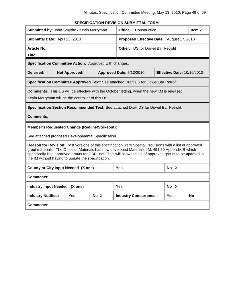
Minutes, Specification Committee Meeting, May 13, 2010, Page 49 of 69
SPECIFICATION REVISION SUBMITTAL FORM
Submitted by: John Smythe / Kevin Merryman Office: Construction Item 21
Submittal Date: April 23, 2010 Proposed Effective Date: August 17, 2010
Article No.:
Title:
Other: DS for Dowel Bar Retrofit
Specification Committee Action: Approved with changes.
Deferred: Not Approved: Approved Date: 5/13/2010 Effective Date: 10/19/2010
Specification Committee Approved Text: See attached Draft DS for Dowel Bar Retrofit.
Comments: This DS will be effective with the October letting, when the new I.M is released.
Kevin Merryman will be the controller of this DS.
Specification Section Recommended Text: See attached Draft DS for Dowel Bar Retrofit.
Comments:
Member’s Requested Change (Redline/Strikeout):
See attached proposed Developmental Specification
Reason for Revision: Past versions of this specification were Special Provisions with a list of approved grout materials. The Office of Materials has now developed Materials I.M. 491.20 Appendix B which specifically lists approved grouts for DBR use. This will allow the list of approved grouts to be updated in the IM without having to update the specification.
County or City Input Needed (X one) Yes No X
Comments:
Industry Input Needed (X one) Yes No X
Industry Notified: Yes No X Industry Concurrence: Yes No
Comments:

Minutes, Specification Committee Meeting, May 13, 2010, Page 50 of 69
DRAFT DS-090XX (New)
DEVELOPMENTAL SPECIFICATIONS FOR
DOWEL BAR RETROFIT
Effective Date August 17, 2010
THE STANDARD SPECIFICATIONS, SERIES 2009, ARE AMENDED BY THE FOLLOWING MODIFICATIONS AND ADDITIONS. THESE ARE DEVELOPMENTAL SPECIFICATIONS AND THEY SHALL PREVAIL OVER THOSE PUBLISHED IN THE STANDARD SPECIFICATIONS. 090XX.01 DESCRIPTION. Install epoxy coated dowel bars on transverse joints and transverse cracks as shown in the plans. Place dowels after concrete repair operations and prior to diamond planing operation. Areas with random cracks passing through dowel bar retrofit locations will be reviewed by the Engineer prior to construction. 090XX.02 MATERIALS.
A. Epoxy Coated Dowel Bars.
1. Ensure epoxy coated dowel bars, 1.5 x 15 inches (40 mm x 375 mm), conform to requirements of Section 4151 of the Standard Specifications. Uniformly coat dowel bars with approved bond breaker according to Article 4151.02, B, of the Standard Specifications.
2. Dowel bars shall have tight fitting end caps made of nonmetallic material that allow for at least 0.25 inch (6 mm) bar movement at each end of the bar.
3. Chair devices for supporting dowel bars shall be either epoxy coated or made of a nonmetallic material. Chair devices shall provide a minimum clearance of 0.5 inch (12 mm) between the bottom of the bar and the surface upon which the bar is placed, and between the bar and the walls of the slot. Chairs shall be designed to prevent movement of the bar during placement of the grout. Submit samples of end caps and chairs to Engineer for approval before installation.
B. Caulking Filler.
Acceptable caulking filler used for sealing the existing transverse joint or crack at the bottom and sides of the slot includes any commercial caulk designed as a concrete sealant that is compatible with the patch material being used.
C. Foam Core Inserts.
Foam core board filler material shall be a closed cell foam faced with plastic film, foil, or poster board material on each side. Foam core board filler shall be 3/8 inch ± 1/8 inch (9 mm ± 3 mm) thick. Foam core board filler shall be approved by the Engineer before installation.
D. Grout.
1. Grout material placed around bars shall be a shrinkage compensated rapid set patch material

Minutes, Specification Committee Meeting, May 13, 2010, Page 51 of 69
listed in Materials I.M. 491.20 Appendix B. 2. Extend grout according to the manufacturer’s recommendations. Aggregate for extending
grout shall be pea gravel meeting Section 4112 of the Standard Specifications, with a minimum durability of Class 2 and the following gradation:
Sieve Size Percent Passing 1/2 inch (12.5 mm) 100 3/8 inch (9.5 mm) 85-100 No. 8 (2.36 mm) 0-8
3. The rapid set cement used to produce any of the rapid set patch materials in Materials I.M. 491.20 Appendix B may be approved to produce a concrete patch mix utilizing sand meeting Section 4110 of the Standard Specifications and pea gravel meeting Section 4112, at maximum aggregate extension. Concrete patch mix shall meet the following strength requirements: • 3 hour minimum compressive strength of 3000 psi (21 MPa), ASTM C 39 • 24 hour minimum compressive strength of 5000 psi (34 MPa), ASTM C 39 • 24 hour bond to dry PCC, 1000 psi (7 MPa), ASTM C 882
4. Furnish a list of materials for use in making the grout, and the mix design, to the Engineer at
least 30 calendar days prior to installation. The District Materials Engineer may waive mix design testing based on previous testing with the patching materials.
5. Testing of the grout by the Engineer may be done anytime during production.
090XX.03 CONSTRUCTION.
A. PROCESS CONTROL PLAN.
Provide the Engineer a process control plan at least one week prior to the beginning of retrofit work. This plan shall include: • Description of materials and process to be used to achieve required dowel bar alignment. • Description of materials and processes to be used to prevent grout from entering existing
joints. • Description of materials and processes to be used to place and align foam core inserts. • Mix design and proportion control for grout mixture
B. Preparing Slots for Dowel Bars.
1. Cut slots in pavement with gang saw capable of cutting at least three slots in each wheel path silmultaneously. Cut slots to required depth to place center of dowels at mid-depth of concrete slab. Multiple saw cuts parallel to centerline may be required to remove material from slot.
2. Use jackhammers not larger than 30-pound class to remove concrete from slots. Prevent damage to pavement or vehicles traveling in the adjoining lane.
3. Sandblast and clean exposed surfaces and cracks in slots before bar installation. Fill transverse contraction joint on bottom and sides with non-sag caulking filler.
C. Placing Dowel Bars.
1. Use chair devices to support dowel bars at depth shown on the plans.
2. Place dowel bars parallel to centerline of pavement and parallel to pavement surface.
3. Place dowel bars within ± 1/4 inch (6 mm) of desired alignment.
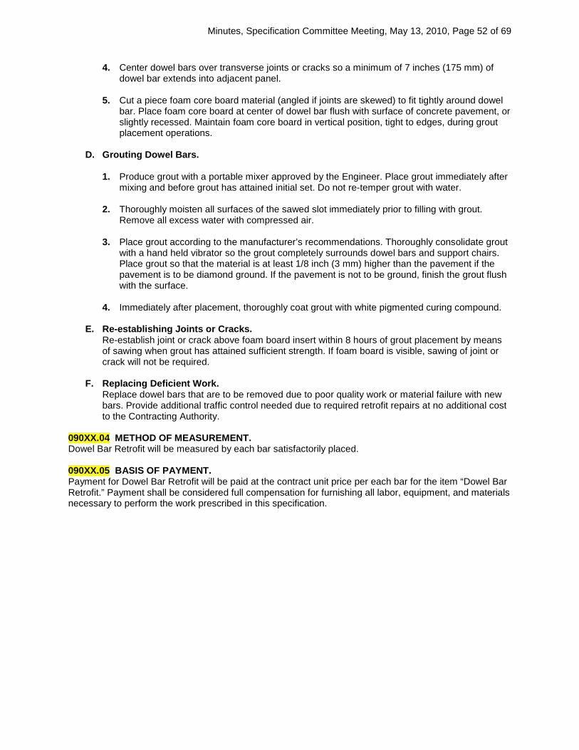
Minutes, Specification Committee Meeting, May 13, 2010, Page 52 of 69
4. Center dowel bars over transverse joints or cracks so a minimum of 7 inches (175 mm) of
dowel bar extends into adjacent panel.
5. Cut a piece foam core board material (angled if joints are skewed) to fit tightly around dowel bar. Place foam core board at center of dowel bar flush with surface of concrete pavement, or slightly recessed. Maintain foam core board in vertical position, tight to edges, during grout placement operations.
D. Grouting Dowel Bars.
1. Produce grout with a portable mixer approved by the Engineer. Place grout immediately after mixing and before grout has attained initial set. Do not re-temper grout with water.
2. Thoroughly moisten all surfaces of the sawed slot immediately prior to filling with grout. Remove all excess water with compressed air.
3. Place grout according to the manufacturer’s recommendations. Thoroughly consolidate grout with a hand held vibrator so the grout completely surrounds dowel bars and support chairs. Place grout so that the material is at least 1/8 inch (3 mm) higher than the pavement if the pavement is to be diamond ground. If the pavement is not to be ground, finish the grout flush with the surface.
4. Immediately after placement, thoroughly coat grout with white pigmented curing compound.
E. Re-establishing Joints or Cracks. Re-establish joint or crack above foam board insert within 8 hours of grout placement by means of sawing when grout has attained sufficient strength. If foam board is visible, sawing of joint or crack will not be required.
F. Replacing Deficient Work.
Replace dowel bars that are to be removed due to poor quality work or material failure with new bars. Provide additional traffic control needed due to required retrofit repairs at no additional cost to the Contracting Authority.
090XX.04 METHOD OF MEASUREMENT. Dowel Bar Retrofit will be measured by each bar satisfactorily placed. 090XX.05 BASIS OF PAYMENT. Payment for Dowel Bar Retrofit will be paid at the contract unit price per each bar for the item “Dowel Bar Retrofit.” Payment shall be considered full compensation for furnishing all labor, equipment, and materials necessary to perform the work prescribed in this specification.
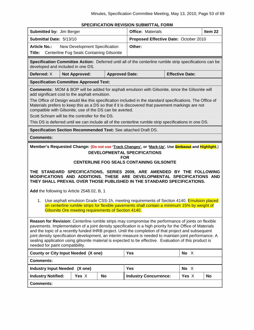
Minutes, Specification Committee Meeting, May 13, 2010, Page 53 of 69
SPECIFICATION REVISION SUBMITTAL FORM Submitted by: Jim Berger Office: Materials Item 22
Submittal Date: 5/13/10 Proposed Effective Date: October 2010
Article No.: New Development Specification Title: Centerline Fog Seals Containing Gilsonite
Other:
Specification Committee Action: Deferred until all of the centerline rumble strip specifications can be developed and included in one DS.
Deferred: X Not Approved: Approved Date: Effective Date:
Specification Committee Approved Text:
Comments: MOM & BOP will be added for asphalt emulsion with Gilsonite, since the Gilsonite will add significant cost to the asphalt emulsion. The Office of Design would like this specification included in the standard specifications. The Office of Materials prefers to keep this as a DS so that if it is discovered that pavement markings are not compatible with Gilsonite, use of the DS can be averted. Scott Schram will be the controller for the DS. This DS is deferred until we can include all of the centerline rumble strip specifications in one DS.
Specification Section Recommended Text: See attached Draft DS.
Comments:
Member’s Requested Change: (Do not use ‘Track Changes’, or ‘Mark-Up’. Use Strikeout and Highlight.) DEVELOPMENTAL SPECIFICATIONS
FOR CENTERLINE FOG SEALS CONTAINING GILSONITE
THE STANDARD SPECIFICATIONS, SERIES 2009, ARE AMENDED BY THE FOLLOWING MODIFICATIONS AND ADDITIONS. THESE ARE DEVELOPMENTAL SPECIFICATIONS AND THEY SHALL PREVAIL OVER THOSE PUBLISHED IN THE STANDARD SPECIFICATIONS. Add the following to Article 2548.02, B, 1
1. Use asphalt emulsion Grade CSS-1h, meeting requirements of Section 4140. Emulsion placed
on centerline rumble strips for flexible pavements shall contain a minimum 15% by weight of Gilsonite Ore meeting requirements of Section 4140.
Reason for Revision: Centerline rumble strips may compromise the performance of joints on flexible pavements. Implementation of a joint density specification is a high priority for the Office of Materials and the topic of a recently funded IHRB project. Until the completion of that project and subsequent joint density specification development, an interim measure is needed to maintain joint performance. A sealing application using gilsonite material is expected to be effective. Evaluation of this product is needed for paint compatibility.
County or City Input Needed (X one) Yes No X
Comments:
Industry Input Needed (X one) Yes No X
Industry Notified: Yes X No Industry Concurrence: Yes X No
Comments:

Minutes, Specification Committee Meeting, May 13, 2010, Page 54 of 69
Draft DS-090XX (New)
DEVELOPMENTAL SPECIFICATIONS FOR
CENTERLINE FOG SEALS CONTAINING GILSONITE
Effective Date October 19, 2010
THE STANDARD SPECIFICATIONS, SERIES 2009, ARE AMENDED BY THE FOLLOWING MODIFICATIONS AND ADDITIONS. THESE ARE DEVELOPMENTAL SPECIFICATIONS AND THEY SHALL PREVAIL OVER THOSE PUBLISHED IN THE STANDARD SPECIFICATIONS. Add the following to Article 2548.02, B, 1.
1. Use asphalt emulsion Grade CSS-1h, meeting requirements of Section 4140. Emulsion placed on
centerline rumble strips for flexible pavements shall contain a minimum 15% by weight of Gilsonite Ore meeting requirements of Section 4140 with the following modifications:
Tests on Residue from Distillation, or Evaporation i. Viscosity at 275°F (135°C) ASTM D 4402 = 1.750 Pa(s) max. ii. Penetration AASHTO T 49 = 50 dmm max.
Furnish a certificate of compliance for each load shipped which contains the following minimum information:
a. A statement by the Supplier that the material shipped complies with the contract documents, and that the product contains a minimum 15% Gilsonite.
b. The specific gravity at 60°F (15.5°C) and the net gallons at 60°F (15.5°C). c. The name of the product, the date the product was loaded onto transport, and
identification of the transport. d. An authorized supplier employee signature.
Add the following to Article 2548.04, Method of Measurement.
D. Asphalt Emulsion with Gilsonite for Fog Seal (For Milled Centerline Rumble Strips). Gallons (liters) as provided for in Article 2307.04, B.
Add the following to Article 2548.05, Basis of Payment.
D. Asphalt Emulsion with Gilsonite for Fog Seal (For Milled Centerline Rumble Strips). 1. Per gallon (liter) for undiluted Asphalt Emulsion with Gilsonite for Fog Seal (For Milled Centerline
Rumble Strips) that is mixed and used on the project. Diluted asphalt emulsion that is delivered to the project site, but not applied to the roadway surface will not be considered for payment.
2. Payment is full compensation for cleaning the shoulder surface, furnishing and applying diluted asphalt
emulsion with Gilsonite, mixing water, and protecting the adjacent pavement and edge lines.

Minutes, Specification Committee Meeting, May 13, 2010, Page 55 of 69
SPECIFICATION REVISION SUBMITTAL FORM Submitted by: John Smythe / Wayne Sunday Office: Construction Item 23
Submittal Date: April 23, 2010 Proposed Effective Date: August 17, 2010
Article No.: DS-09XXX Title:
Other: DS for Mass Concrete – Control of Heat of Hydration
Specification Committee Action: Approved with changes.
Deferred: Not Approved: Approved Date: 5/13/2010 Effective Date: 8/17/2010
Specification Committee Approved Text: See attached Draft DS for Mass Concrete – Control of Heat of Hydration.
Comments: The Office of Construction outlined the history of the two SP’s that were combined for this DS. The FHWA questioned the list of potential corrective actions listed in the DS. Removal of non-complying concrete was added to the list of potential corrective actions. The Office of Bridges and Structures asked if the work described in the DS should be incidental to structural concrete. Typically, the more costly requirements in the DS will only apply to very large bridges, such as border river bridges which the Iowa DOT does not let very often. Also, the volume of concrete in these bridges is such that the requirements of this DS will not be enough to greatly skew the bid price. The Office of Bridges and Structures questioned requiring cooling pipes. Cooling pipes will only be required when the structural element is below water level and within the limits of the river. The Office of Bridges and Structures asked about the use of “this Engineer” vs. “the Engineer”. Sometimes we are referring to the contracting authority’s representative and sometimes we are referring to the engineer who develops the Thermal Control Plan. The Specifications Section has reviewed the DS and will refer to the engineer who develops the Thermal Control Plan as the TC Engineer. Wayne Sunday will be the controller of this DS.
Specification Section Recommended Text: See attached Draft DS for Mass Concrete – Control of Heat of Hydration.
Comments:
Member’s Requested Change: (Do not use ‘Track Changes’, or ‘Mark-Up’.Use Strikeout and Highlight. Refer to attached DS.
Reason for Revision: Prior to this proposed DS there existed two Special Provisions for Mass Concrete – Control of Heat of Hydration. One SP was for structural concrete elements with a least dimension greater than 4 feet and the other SP was developed and first implemented on the I-80 Missouri River bridge project and had requirements for a Thermal Control Plan and mass concrete temperature control developed by a Professional Engineer licensed in the State of Iowa competent in the modeling, design, and temperature control of concrete in mass elements. The purpose of this DS is to have one document that addresses all Mass Concrete placements, whether they are small or large. This DS has been developed with specific requirements associated with Mass Concrete placements with a least dimension of less than or equal to 6.5 feet and more stringent requirements for Mass Concrete placements with a least dimension greater than 6.5 feet. This single DS will be able to be used for either Mass Concrete size condition and will eliminate the multiple SPs that were previously used.
County or City Input Needed (X one) Yes No
Comments:
Industry Input Needed (X one) Yes No

Minutes, Specification Committee Meeting, May 13, 2010, Page 56 of 69
Industry Notified:
Yes No Industry Concurrence:
Yes No
Comments:

Minutes, Specification Committee Meeting, May 13, 2010, Page 57 of 69
DRAFT DS-090XX (New)
DEVELOPMENTAL SPECIFICATIONS
FOR MASS CONCRETE – CONTROL OF HEAT OF HYDRATION
Effective Date August 17, 2010
THE STANDARD SPECIFICATIONS, SERIES 2009, ARE AMENDED BY THE FOLLOWING MODIFICATIONS AND ADDITIONS. THESE ARE DEVELOPMENTAL SPECIFICATIONS AND THEY SHALL PREVAIL OVER THOSE PUBLISHED IN THE STANDARD SPECIFICATIONS.
090XX.01 DESCRIPTION. Produce a structure free of shrinkage cracks that would be a result of heat of hydration during the curing of large concrete cross-sections. Accomplish this through appropriate concrete mix design and management of concrete temperature and temperature differential. Structural mass concrete is defined as any concrete footing with a least dimension greater than 5 feet (1.5 m) or other concrete placements with a least dimension greater than 4 feet (1.2 m). Additional constraints are required on placements with a least dimension greater than 6.5 feet (2 m). This specification does not apply to concrete drilled shafts. Apply Section 2403 and Division 41 of the Standard Specifications with the following modifications. 090XX.02 MATERIALS.
A. Cement shall be Type I/II, IP, or IS. B. Use any combination of Ground Granulated Blast Furnace Slag or Class F fly ash. Class C fly
ash may also be used with a maximum substitution of 20%. The maximum total substitution of Portland cement shall not exceed 50%, including the amount in the blended cement.
C. Cement content shall be a minimum of 560 pounds per cubic yard (332 kg/m3). D. Maximum water to cementitious ratio shall be 0.45. E. Air entrainment shall be used. To improve workability and aid in air entrainment, water reducing
or retarding admixtures may be used. A mid range water reducing admixture may be used and the slump shall be increased to six inches maximum.
090XX.03 CONSTRUCTION.
A. THERMAL CONTROL PLAN. Develop and submit a written Thermal Control Plan describing the procedures that will be used during the period of heat dissipation following concrete placement, so the temperature differential between the interior of the section and the outside surface of the section does not exceed the restrictions in Article 090XX.04, B. Submit the Thermal Control Plan at least 30 calendar days before the first intended structural mass concrete placement. Compliance with this specification may result in long cooling times. Consider options to control heat of hydration that are compatible with their desired construction schedule and erection procedures.

Minutes, Specification Committee Meeting, May 13, 2010, Page 58 of 69
Do not place concrete covered by this specification until the Thermal Control Plan has received written approval by the Engineer and equipment and materials necessary to facilitate the plan are on site and ready for use. Provide and install temperature sensing devices according to Article 090XX.04 C. The location of construction joints shall be as shown in the plans. For mass concrete placements with a least dimension of less than or equal to 6.5 feet (2 m) the Thermal Control Plan procedures may include, but are not limited to, the following: Cooling component materials prior to addition to the mix to reduce the temperature of the
concrete while in its plastic state. Adding ice to the mix water. Sprinkle coarse aggregate with water or wet the stockpile. Controlling rate of concrete placement (low lifts). Insulating the forms and the surface of the concrete to prevent temperature differential. Placing concrete at times of day when the ambient temperature is lowest (in summer) or highest
(in winter). Other acceptable methods that may be developed by the Contractor and approved in writing by
the Engineer. For mass concrete placements with a least dimension of greater than 6.5 feet (2 m), the Thermal Control Plan shall be developed by a Professional Engineer, licensed in the State of Iowa and competent in the modeling, design, and temperature control of concrete in mass elements (T. C. Engineer). The T. C. Engineer shall submit a list containing at least three mass concrete projects, of similar dimension and thermal control requirements to those shown on the plans, completed in the last three years. In the list of projects include names and phone numbers of owner's representatives who can verify the T. C. Engineer's participation on those projects. The T. C. Engineer shall follow the procedure outlined in Section 207.4R-05 of the ACI Manual of Cooling and Insulating Systems for Mass Concrete to formulate, implement, administer, and monitor a temperature control plan, making adjustments as necessary to ensure compliance with the Contract Documents. The Thermal Control Plan shall include, but not be limited to the following:
1. Based on the concrete mix design, determine by lab testing the adiabatic heat generation for the concrete mix to be used.
2. Proposed methods to achieve required concrete temperature and control concrete
temperature differential through concrete mix design and construction practices for temperature control to prevent thermal cracking.
3. Design of a cooling system consisting of non-corrosive piping to be embedded in the
structural mass concrete for all mass concrete placements that are below water level within the limits of the river.
4. Provide information on the temperature sensing and recording equipment to be used and
details of installation locations of the temperature probes for each planned mass concrete placement.
5. Mass concrete placement plan to ensure prevention of concrete cold joints. 6. Monitoring Plan to control temperature gradient.
B. THERMAL CONTROL.
1. Concrete Temperature Limits. Maximum concrete temperature at time of placement shall not exceed 70ºF (21°C) and shall not

Minutes, Specification Committee Meeting, May 13, 2010, Page 59 of 69
be less than 40ºF (4°C). The maximum concrete temperature during the period of heat dissipation shall not exceed 160ºF (71°C). 2. Temperature Differential Restrictions The temperature differential between the interior of the section and the outside surface of the section shall not exceed the limit in the following table:
Hours after placement
Maximum temperature differential °F (°C)
0-24 20 (11.1) 24-48 30 (16.7) 48-72 40 (22.2) >72 50 (27.8)
Thermal control of each placement shall be maintained until the temperature of the interior is within 50ºF (27.8°C) of the average outside air temperature. The average outside air temperature shall be determined by averaging the daily high and low temperatures over the preceding seven calendar days. 3. Temperature Sensing and Recording For each placement of structural mass concrete, two temperature sensors shall be installed at each of the following locations (for a total of ten temperature sensors): • center of the placement, • midpoint of the side which is the shortest distance from the center (minimum 2 inch (50 mm)
cover), • midpoint of the top surface (minimum 2 inch (50 mm) cover), • corner of the placement which is furthest distance from the center (minimum 2 inch (50 mm)
cover), and • air temperature. The purpose for two sensors at each location is to provide a primary and secondary backup. Temperatures shall be electronically recorded automatically by an approved recorder furnished by the Contractor and shall be capable of continuously recording a minimum of one reading per hour for the duration of the mass concrete temperature monitoring period. Sensors and recorder shall be accurate to within +/- 2ºF (1.1°C) in the temperature range of 32ºF (0°C) to 212ºF (100°C). Provide a backup temperature sensing system, which shall include both backup temperature sensors and backup temperature readout device. Back-up system is intended to be used to complete the monitoring of a placement should the primary system fail. Primary system shall be repaired or replaced before the commencement of the next placement.
C. PRODUCTION CONCRETE.
1. The T. C. Engineer or qualified technician employed by the T. C. Engineer, shall personally inspect and approve the installation of monitoring devices and verify the process for recording temperature data is effective for the first placement of each size and type mass component. Qualifications of all technicians employed to inspect or monitor mass concrete placements shall be submitted to the Engineer for approval. For placements other than the first, an employee, approved by the T. C. Engineer as qualified to inspect monitor device installation, shall be designated to: 1) review temperature data, 2) be in contact at all times with the Engineer if adjustments must be made as a result of the temperature differential being exceeded, and 3) immediately implement adjustments to temperature control measures as directed by the T. C. Engineer. Recorded temperature data shall be reviewed at intervals of no greater than 4 hours. Recording of temperature data shall begin when the mass concrete placement is complete and shall continue until the maximum temperature differential (not maximum temperature) is reached and a decreasing temperature differential is confirmed as defined in the Thermal Control Plan. If conditions change, such as a drop in the ambient temperature or a change in insulation which

Minutes, Specification Committee Meeting, May 13, 2010, Page 60 of 69
would result in an increase in the temperature differential, the recording of temperature data shall be resumed. A copy of all recorded temperature data shall be furnished to the Engineer as they are determined, and a final report shall be furnished within 3 days of completion of monitoring of each element.
Only use approved mixes for production concrete
2. If the temperature differential within any structural mass concrete placement exceeds the limits in Article 090XX.04 B , immediate corrective action as directed by the Contractor or the T. C. Engineer shall be taken, future placement of structural mass concrete will be suspended, and a revised Thermal Control Plan shall be submitted to the Engineer for approval. Do not resume placement of mass concrete without written approval from the Engineer. When mass concrete temperature differentials are exceeded, all analyses and test results deemed necessary by the Engineer shall be provided for determining the structural integrity and durability of the mass concrete element, to the satisfaction of the Engineer. The analyses and/or test results shall be provided at no additional cost to the Contracting Authority and without additional time to be granted. Based on the analyses and test results, a determination of corrective action will be made by the Engineer which may include, but not be limited to, price adjustment, epoxy injection of thermal cracks, a combination of both, or removal of the non-complying concrete.
090XX.04 METHOD OF MEASUREMENT. None. 090XX.05 BASIS OF PAYMENT. Costs for complying with this specification shall be considered incidental to the contract unit price for structural concrete.

Minutes, Specification Committee Meeting, May 13, 2010, Page 61 of 69
SPECIFICATION REVISION SUBMITTAL FORM
Submitted by: Jim Berger Office: Materials Item 24
Submittal Date: Proposed Effective Date: August 2010
Article No.:
Other: DS for Structural Concrete 4500 psi (31.03 MPa) or Greater
Specification Committee Action: Approved with changes.
Deferred: Not Approved: Approved Date: 5/13/2010 Effective Date: 10/19/2010
Specification Committee Approved Text: See attached Draft DS for Structural Concrete (4500 psi (31 MPa) or Greater).
Comments: The Office of Bridges and Structures questioned the DS title and bid item names. “or Greater” was added to show that this specification can be used for any required strength 4500 psi or greater.
Ahmad Abu-Hawash will be the controller of this DS.
Specification Section Recommended Text: See attached Draft DS.
Comments:
Member’s Requested Change (Redline/Strikeout):
Attached DS
Reason for Revision:
County or City Input Needed (X one) Yes No
Comments:
Industry Input Needed (X one) Yes No
Industry Notified: Yes No Industry Concurrence: Yes No
Comments: This DS is to be used when the Bridge office has certain structural elements which require higher compressive strength. Typically, 3500 psi is used for standard bridges, certain designs require higher compressive strengths. A Class C mix will usually meet the higher requirements, although there are areas in the state where it may be harder to achieve as a minimum. This DS requires documentation to ensure the Class C mix will meet the minimum required strength or submit a new mix design to meet the strength requirements. This way we are not specifying a mix design and a compressive strength requirement. If we specify a mix and require a strength requirement, we are accountable to make changes if the mix does not meet the requirements.
This concept has been used before in SP-95993 and has been included in various other structural specifications.
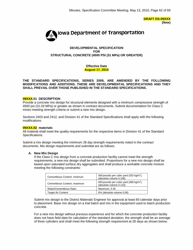
Minutes, Specification Committee Meeting, May 13, 2010, Page 62 of 69
DRAFT DS-09XXX (New)
DEVELOPMENTAL SPECIFICATION FOR
STRUCTURAL CONCRETE (4500 PSI (31 MPa) OR GREATER)
Effective Date August 17, 2010
THE STANDARD SPECIFICATIONS, SERIES 2009, ARE AMENDED BY THE FOLLOWING MODIFICATIONS AND ADDITIONS. THESE ARE DEVELOPMENTAL SPECIFICATIONS AND THEY SHALL PREVAIL OVER THOSE PUBLISHED IN THE STANDARD SPECIFICATIONS. 09XXX.01 DESCRIPTION Provide a concrete mix design for structural elements designed with a minimum compressive strength of 4500 psi (31.03 MPa) or greater as shown in contract documents. Submit documentation for Class C mixes meeting strength criteria or submit a new mix design. Sections 2403 and 2412, and Division 41 of the Standard Specifications shall apply with the following modifications. 09XXX.02 materials All material shall meet the quality requirements for the respective items in Division 41 of the Standard Specifications. Submit a mix design meeting the minimum 28 day strength requirements noted in the contract documents. Mix design requirements and submittal are as follows:
A. New Mix Design
If the Class C mix design from a concrete production facility cannot meet the strength requirements, a new mix design shall be submitted. Proportions for a new mix design shall be based upon saturated surface dry aggregates and shall produce a workable concrete mixture meeting the following constraints:
Cementitious Content, minimum 560 pounds per cubic yard (332 kg/m3), (absolute volume 0.106)
Cementitious Content, maximum 650 pounds per cubic yard (385 kg/m3), (absolute volume 0.123)
Water/Cementitious Ratio Maximum, 0.45 Target Air Content 6% (absolute volume 0.06)
Submit mix design to the District Materials Engineer for approval at least 60 calendar days prior to placement. Base mix design on a trial batch and mix in the equipment used to batch production concrete. For a new mix design without previous experience and for which the concrete production facility does not have field data for calculation of the standard deviation, the strength shall be an average of three cylinders and shall meet the following strength requirement at 28 days as shown below.

Minutes, Specification Committee Meeting, May 13, 2010, Page 63 of 69
Specified minimum compressive strength, ƒ’c psi (MPa)
Required average compressive strength, ƒ’c
4500 to 5000 (31.03 to 34.47) ƒ’c + 1200 psi (8.27 MPa) Greater than 5000 (34.47) ƒ’c + 1400 psi (9.65 MPa)
where, ƒ’c = specified compressive strength in contract documents If the concrete production facility has test records for calculation of the standard deviation, the required 28 day compressive strength shall be as shown in Article 09XXX.02 B. Concrete shall represent materials, quality control procedures, conditions, materials and proportions within test records, and the mix design represented shall not have been more restricted than the proposed mix. Strength represented by test records shall be within 1000 psi (6.89 MPa) of the required compressive strength.
B. Mix Design with History of Strength
A Class C mix, or other mixes with satisfactory record of strength, may be submitted in lieu of a new mix design. In accordance with ACI 301, a minimum of 30 tests for 28 day compressive strength shall be required as supporting documentation. The concrete produced for this specification shall be produced in accordance with Section 2403 of the Standard Specifications, representing material sources (fly ash source changes may be included), and shall be batched and mixed in the same equipment used to produce the concrete represented by the performance strength documentation. The standard deviation shall be calculated from the 30 strength tests, except as provided below. The required 28 day compressive strength, ƒ’c, shall be the greater of the following ƒ’c + 1.34 s or ƒ’c + 2.33 s – 500 psi (3.45 MPa) where: ƒ’c = specified compressive strength in contract documents
s = standard deviation. When the concrete production facility has less than 30 tests (15 to 29), the standard deviation shall be increased by the factor included in the following table:
Number of tests* Factors for increasing the Standard Deviation
15 1.16 20 1.08 25 1.03
30 or more 1.00 *Less than 15 tests shall require a new mix design.
Submit modifications to an accepted concrete mix design to the Engineer for review and approval prior to use. 09XXX.03 CONSTRUCTION.
A. Trial Batch Concrete. A trial batch will be required for any new mix design or any mix design with a history of strength without past experience on Interstate and primary projects. Approval will be based on trial batch mix properties and submittal of a trial batch report. The District Materials Engineer may waive the trial batch testing and perform testing on initial production placements where lower strengths are required, provided the concrete production facility produces acceptable test records for proposed mix demonstrating mix properties have been achieved through previous trial batches. The District Materials Engineer shall be afforded ample opportunity to witness the trial batching. The District Materials Engineer shall be given notice and mix proportions 7 calendar days prior to this event. The trial batch shall be made at least 30 calendar days prior to planned placement and shall be a minimum of 3 cubic yards (cubic meters) in size. Establish batching sequence during

Minutes, Specification Committee Meeting, May 13, 2010, Page 64 of 69
trial batch. Transport the concrete a distance comparable to the distance from the ready mix plant to the placement site. Use concrete for testing representative of the entire batch while having a slump within 1 inch (25 mm) of the maximum slump allowed, an intended in place air content of 6% ± 1%, and a w/c ratio that will be typical in the placement. Perform the following tests for each trial batch:
Specific Gravity of Each Individual Aggregate Materials I.M. 307 Gradation of Each Individual Aggregate Materials I.M. 302 Unit Weight of Plastic Concrete Materials I.M. 340 Slump of Plastic Concrete Materials I.M. 317 Air Content of Plastic Concrete Materials I.M. 318
Submit a trial batch mix design report and include the following:
Cover Page Contractor and Producer Name Project Number Date and Location of Trial Batch Date Submitted Signature of Contractor/Producer Representative
Material Source Information Brand, Type, and Source Proportion Information Specific Gravity
Relative % of Each Individual Aggregate Design and As Mixed Batch Weights (SSD) Design and As Mixed w/c Ratios
Mix Properties Unit Weight of Plastic Concrete Air Content of Plastic Concrete Slump Individual Compressive Strength results at 7 and 28 days
B. Production Concrete.
Perform quality control testing of production concrete for strength to determine if production concrete meets the minimum required design strength. Cast, cure, and handle strength samples according to Materials I.M. 315 using a PCC Level I Concrete Field Testing Technician. At the site ensure cylinders are cured properly with wet burlap and plastic. Do not move cylinders for 16 hours and ensure they remain at the site for a maximum of 1 calendar day before being transported to a certified laboratory for final curing and testing. Cast six strength samples in 4 inch by 8 inch (100 mm by 200 mm) cylinder molds for each lot. A lot shall be one week of concrete production. For production less than 50 cubic yards (38 cubic meters) per week, obtaining samples for strength will be grouped with a previous or subsequent week. Document slump, air content, and w/c ratio (adjusted for all water) of the concrete for the cylinders cast. Test strength samples by a certified lab in accordance with AASHTO T 22. Test three cylinders for strength at each age of 28 and 56 days. Submit test results to the Engineer and the District Materials Engineer no later than 1 working day after testing is completed. Submittal shall clearly indicate the project number, location, Contractor, producer, structural element constructed, slump, air content, w/c ratio (adjusted for all water), date sampled, date tested, break age, individual compressive strengths, and average compressive strengths. Attach plant report for the placement to the submittal. The District Materials Engineer will obtain random verification strength samples at a minimum rate of a set for at least one substructure placement and a set for at least one deck placement. A set of six 4 inch by 8 inch (100 mm by 200 mm) cylinders will be cast, cured, and handled in accordance with Materials I.M. 315. Three cylinders will be tested for strength at 28 days and three cylinders will be held for further testing, if needed. Strength samples will be tested at the District Materials Laboratory in accordance with AASHTO T 22.
C. Failure to Comply
According to ACI 318, strength is acceptable if the average compressive strength of three cylinders meets the required compressive strength and no individual test falls below the required compressive strength by more than 500 psi (3.45 MPa). When the average 28 day compressive

Minutes, Specification Committee Meeting, May 13, 2010, Page 65 of 69
strength does not meet or exceed the specified strength, propose evaluation methods to determine the in-place concrete strength. Submit the proposal to the Engineer for approval. Notify the Engineer 48 hours in advance of any sampling and testing and will witness the sampling and testing of the in-place concrete. The Engineer will review the results with the Office of Bridges and Structure and determine corrective action required. The Contractor shall be responsible for the cost of evaluation and any corrective action required.
09XXX.04 METHOD OF MEASUREMENT The quantity of Structural Concrete 4500 psi (31 MPa) or Greater, in cubic yards, will be the quantity shown in the contract documents. 09XXX.05 BASIS OF PAYMENT The Contractor will be paid the contract unit price for Structural Concrete 4500 psi (31 MPa) or Greater per cubic yard. The cost for testing the production concrete shall be included in the contract unit price for Structural Concrete 4500 psi (31 MPa) or Greater.

Minutes, Specification Committee Meeting, May 13, 2010, Page 66 of 69
SPECIFICATION REVISION SUBMITTAL FORM Submitted by: Tom Reis Office: Specifications Item 25
Submittal Date: March 26, 2010 Proposed Effective Date: October 2010
Article No.: Title:
Other: Specifications for Safety Edge
Specification Committee Action: Approved with changes.
Deferred: Not Approved: Approved Date: 5/13/2010 Effective Date: 10/19/2010
Specification Committee Approved Text: Add the following Section:
Section 23XX. Safety Edge
23XX.01 DESCRIPTION. Incorporate a Safety Edge to the dimensions shown and at locations designated on the contract documents. 23XX.02 MATERIALS. Safety Edge material shall match the adjoining pavement or shoulder material. 23XX.03 CONSTRUCTION.
A. Asphalt Pavement. Attach a device to the paver screed to confine material at the end gate and extrude the asphalt material in a wedge shape meeting the requirements of the plan details. Maintain contact between the device and road shoulder surface; and allow automatic transition to cross roads, driveways, and obstructions. Use the device to constrain the asphalt head, reducing the area and increasing the density of the extruded profile. Approved devices meeting this specification are listed in Materials I.M. XXX.XX. Use of a single plate strike off will not be allowed.
Alternative devices not listed in Materials I.M. XXX.XX may be approved by the Engineer. The Engineer may require proof that the device has been used on previous projects with acceptable results or may require a test section constructed prior to the beginning of work to demonstrate wedge compaction to the satisfaction of the Engineer. The Engineer may allow short sections of handwork when necessary for transitions at driveways, intersections, interchanges, and bridges. Placement of a granular fillet, per Article 2121.03, C, 4, b, is not necessary when a Safety Edge is installed.
B. PCC Pavement. Modify paver screed to ensure the Safety Edge meets the final cross-section as detailed on the plans.
23XX.04 METHOD OF MEASUREMENT. Safety Edge will not be measured for payment. 23XX.05 BASIS OF PAYMENT. Safety Edge will not be paid for separately and shall be included in the contract unit price for the item for which it is required.
Comments: The approved devices have been removed and will be included in an I.M. to be issued in October. The Office of Contracts was concerned with how local systems will measure pavement including safety edge. Per the Standard Road Plans, the pay width will be the standard pavement width plus 1’, regardless of the actual safety edge width. The Districts will need to enforce our method of determining pay width on local systems projects so that we can maintain consistency.
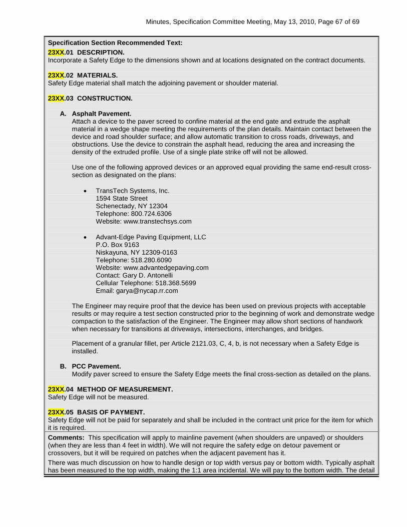
Minutes, Specification Committee Meeting, May 13, 2010, Page 67 of 69
Specification Section Recommended Text: 23XX.01 DESCRIPTION. Incorporate a Safety Edge to the dimensions shown and at locations designated on the contract documents. 23XX.02 MATERIALS. Safety Edge material shall match the adjoining pavement or shoulder material. 23XX.03 CONSTRUCTION.
A. Asphalt Pavement. Attach a device to the paver screed to confine material at the end gate and extrude the asphalt material in a wedge shape meeting the requirements of the plan details. Maintain contact between the device and road shoulder surface; and allow automatic transition to cross roads, driveways, and obstructions. Use the device to constrain the asphalt head, reducing the area and increasing the density of the extruded profile. Use of a single plate strike off will not be allowed. Use one of the following approved devices or an approved equal providing the same end-result cross-section as designated on the plans:
• TransTech Systems, Inc.
1594 State Street Schenectady, NY 12304 Telephone: 800.724.6306 Website: www.transtechsys.com
• Advant-Edge Paving Equipment, LLC P.O. Box 9163 Niskayuna, NY 12309-0163 Telephone: 518.280.6090 Website: www.advantedgepaving.com Contact: Gary D. Antonelli Cellular Telephone: 518.368.5699 Email: [email protected]
The Engineer may require proof that the device has been used on previous projects with acceptable results or may require a test section constructed prior to the beginning of work and demonstrate wedge compaction to the satisfaction of the Engineer. The Engineer may allow short sections of handwork when necessary for transitions at driveways, intersections, interchanges, and bridges. Placement of a granular fillet, per Article 2121.03, C, 4, b, is not necessary when a Safety Edge is installed.
B. PCC Pavement. Modify paver screed to ensure the Safety Edge meets the final cross-section as detailed on the plans.
23XX.04 METHOD OF MEASUREMENT. Safety Edge will not be measured. 23XX.05 BASIS OF PAYMENT. Safety Edge will not be paid for separately and shall be included in the contract unit price for the item for which it is required. Comments: This specification will apply to mainline pavement (when shoulders are unpaved) or shoulders (when they are less than 4 feet in width). We will not require the safety edge on detour pavement or crossovers, but it will be required on patches when the adjacent pavement has it. There was much discussion on how to handle design or top width versus pay or bottom width. Typically asphalt has been measured to the top width, making the 1:1 area incidental. We will pay to the bottom width. The detail

Minutes, Specification Committee Meeting, May 13, 2010, Page 68 of 69
will be revised to show design width and pay width. For asphalt, the safety edge will be shown as a nominal 1 foot. If the Contractor elects to put safety edge in where it is not required, will the additional quantity be paid for or incidental? It was decided this specification will not be issued as a DS, but will go into the October GS. The wording and detail will be finalized so Safety Edge can be added by contract modification prior to the October letting.
Member’s Requested Change: (Do not use ‘Track Changes’, or ‘Mark-Up’. Use Strikeout and Highlight.) See attached Developmental Specification
Reason for Revision: Added specification language to implement a Safety Edge on selected projects.
County or City Input Needed (X one) Yes No X
Comments:
Industry Input Needed (X one) Yes No X
Industry Notified: Yes No X Industry Concurrence: Yes No
Comments:

Minutes, Specification Committee Meeting, May 13, 2010, Page 69 of 69
SPECIFICATION REVISION SUBMITTAL FORM Submitted by: Jim Berger Office: Materials Item 26
Submittal Date: 5/13/2010 Proposed Effective Date: October 2010
Article No.: 4134.02, B Title: Floodable Backfill Material
Other:
Specification Committee Action: Approved.
Deferred: Not Approved: Approved Date: 5/13/2010 Effective Date: 10/19/2010
Specification Committee Approved Text: 4134.02, B
Replace the Article: B. For natural sand use Gradation No. 1 or No. 36 of the Aggregate Gradation Table, Article 4109.02.
Comments: Per the Office of Materials, Gradation No. 1 is slightly coarser than gradation No. 36, but this is not expected to cause any differences.
Specification Section Recommended Text:
Comments:
Member’s Requested Change: (Do not use ‘Track Changes’, or ‘Mark-Up’. Use Strikeout and Highlight.) Add Gradation No. 1 as an acceptable gradation for natural sand.
Reason for Revision: Allows concrete sand to be used for floodable backfill material.
County or City Input Needed (X one) Yes No
Comments:
Industry Input Needed (X one) Yes No
Industry Notified: Yes No Industry Concurrence: Yes No
Comments: