
Minimization of Profile Losses : Local Modifications of Blade Profile P M V Subbarao Professor...
20
Minimization of Profile Losses : Local Modifications of Blade Profile P M V Subbarao Professor Mechanical Engineering Department Now it is Time to Modify Pressure Side. ……
-
Upload
toby-benson -
Category
Documents
-
view
216 -
download
1
Transcript of Minimization of Profile Losses : Local Modifications of Blade Profile P M V Subbarao Professor...

Minimization of Profile Losses : Local Modifications of Blade Profile
P M V SubbaraoProfessor
Mechanical Engineering Department
Now it is Time to Modify Pressure Side.……
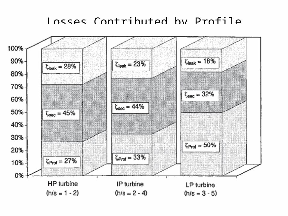
Losses Contributed by Profile

Local Tuning of Blade Shape
xVV
ppC p
'2
21 2
'1'
x
The flow potential is perturbed and hence the local flow is influenced by the airfoil shape/blade shape.

Control of Flow Deceleration on Suction Side

Control of Flow Deceleration on Suction Side
Control of Flow Deceleration on Pressure Side
• For a given profile loading, a certain amount of initial deceleration on the pressure side is helpful
• This allows reduction in the maximum velocity level on the suction side, thereby reducing the overall diffusion on the latter.
• Local changes in design feature in terms of both profile contour change and the corresponding Mach number distribution is helpful in this regard.

Control of Flow Deceleration on Pressure Side
Note that, owing to the lower dynamic head on the pressure side, substantial geometry change is required to produce a
measurable effect on the suction side.
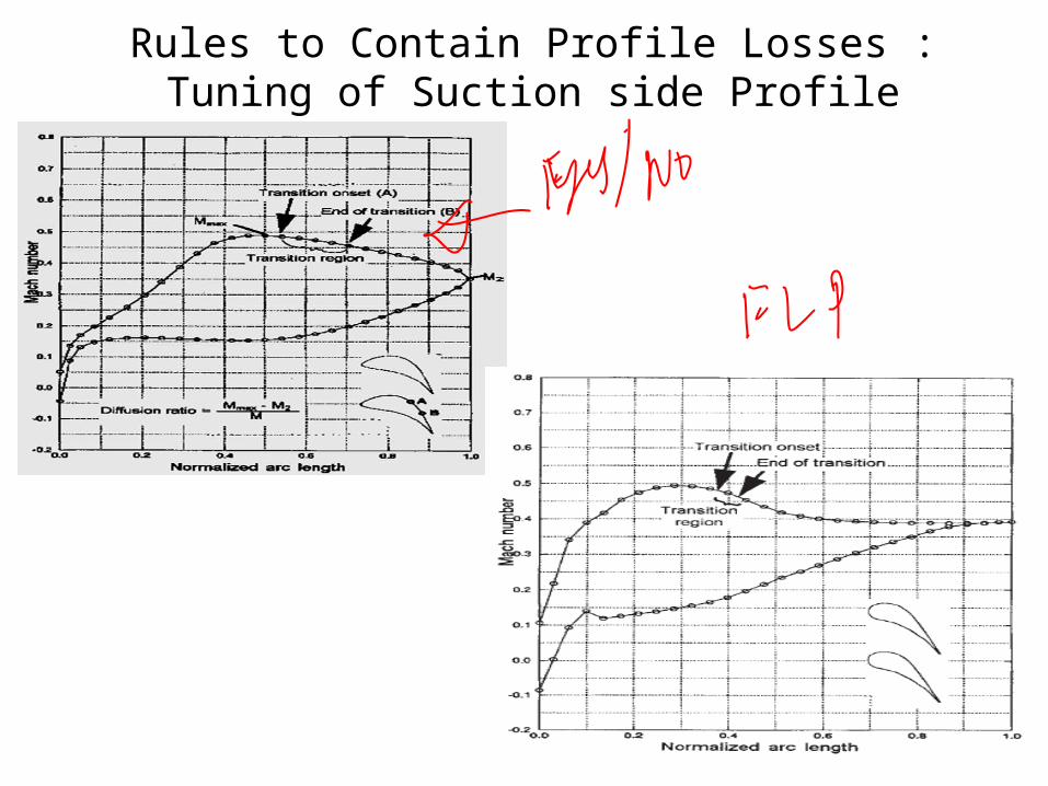
Rules to Contain Profile Losses : Tuning of Suction side Profile
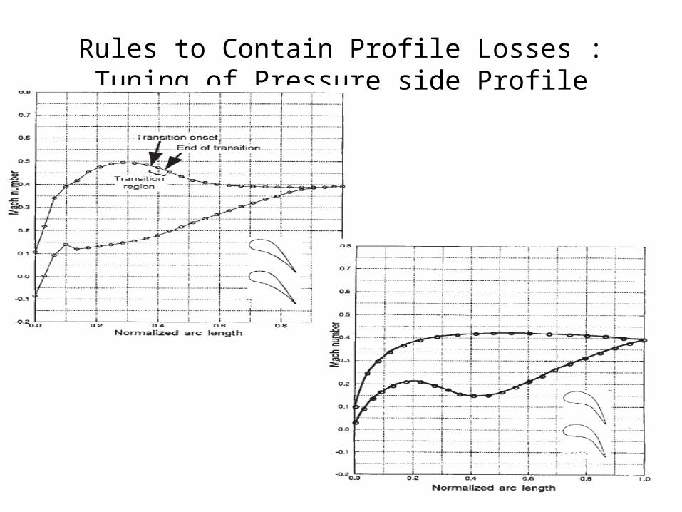
Rules to Contain Profile Losses : Tuning of Pressure side Profile
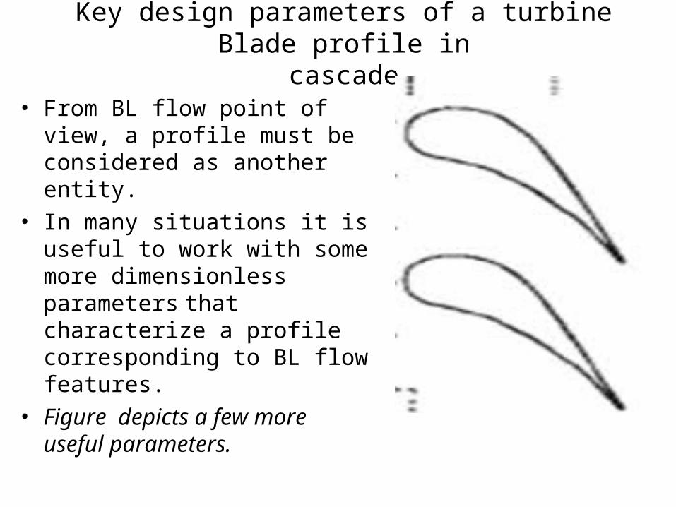
Key design parameters of a turbine Blade profile incascade
• From BL flow point of view, a profile must be considered as another entity.
• In many situations it is useful to work with some more dimensionless parameters that characterize a profile corresponding to BL flow features.
• Figure depicts a few more useful parameters.
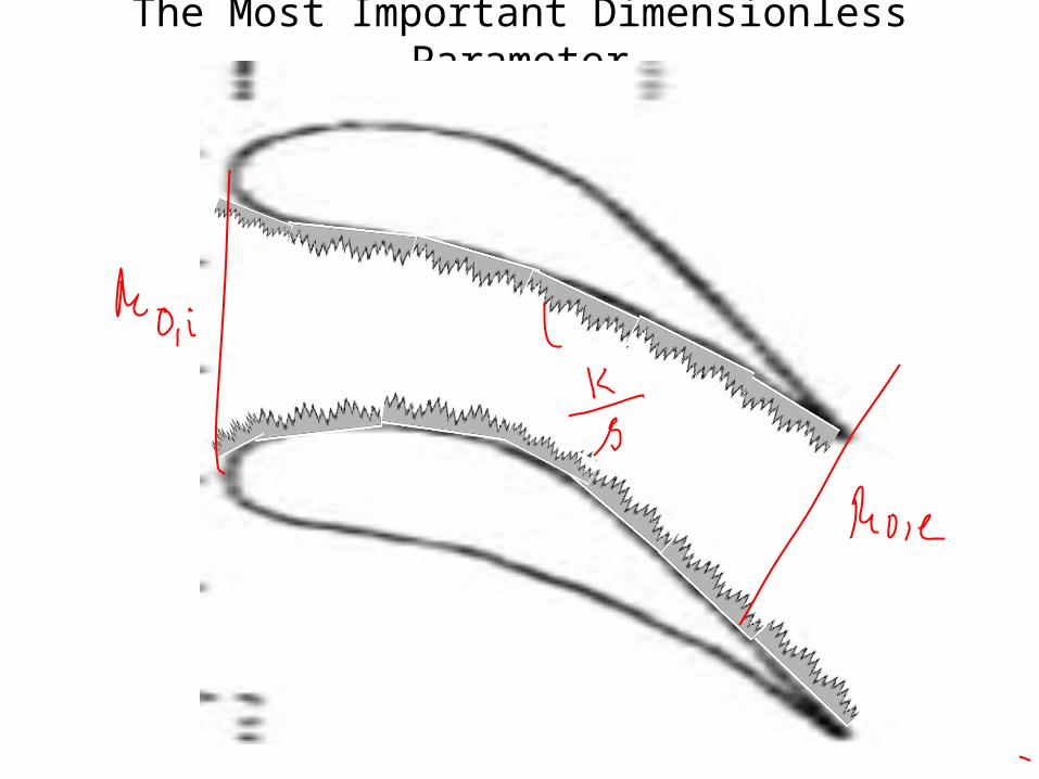
The Most Important Dimensionless Parameter

Frictional Losses
• Stage efficiency losses due to an increase in the measurable roughness of a blade surface will be a function of;
• the ratio of the height of the projections to the thickness of the boundary layer.
• Whether the boundary layer is laminar or turbulent (Reynolds Number).
• The thinner the boundary layer (higher Reynolds Number), the more significant the friction loss becomes, even for small projections.
• Projections are caused by contaminates in the steam which deposit on the surface of the partitions.
• Projections are also caused when foreign particles collide against partition surfaces, leaving behind small indentations in these surfaces.

Loss in stage efficiency as a function of surface Roughness

Need for more fundamental Study of Roughness Effect
• It is customary when evaluating friction losses to divide the airfoil into three regions:
• leading edge,
• suction side trailing edge, and
• Pressure side trailing edge.

Nature of Losses in Nozzle Blade Passage Flow
• Nozzle suction side roughness affects stage efficiency approximately three times more than pressure side roughness.
• The leading edge roughness will have the greatest contribution to stage efficiency loss occurring on the bucket.
• In a nozzle of impulse stage, because of the higher pressure drop through the nozzles, approximately 75% of a stage efficiency loss caused by surface roughness is attributed to the nozzles.

Nature of Losses in Rotor Blade Passage Flow
• Rotor Blade (Bucket) leading edge suction side roughness affects stage efficiency approximately two times more than pressure side roughness.
• This information is affected by turbine section.
• In general Higher Reynolds Numbers are found in the High-Pressure section (smaller boundary layer), the smaller the projections have to be in order to avoid an increase in friction loss.

Need for Identification of Generalized Loss Parameters
• Cascade tests
• Tests on the Rolls-Royce Conway gas turbine
• Range of a number of tests on single stage impulse turbines.
• Tests on a three stage low pressure model steam turbine working into the wet region.

Need for Identification of Generalized Loss Parameters

Profile loss ratio Vs Reynolds number effect
The loss effect of Re on blade cascade performance is pronounced. Thus any correlation of cascade data which neglects the Reynolds number of test is of little value.Typically in the range of Re between 2 l04 and 2 l05 the loss will be halved. A general prediction method for use in steam turbine analysis requires that the effect of Re should be predictable up to values of Re, equal to about 4 l06 which are now obtained at the inlet of modern high pressure (h.p.) cylinders.

Classification of cascade Flow Regimes
More closer study of the flow through cascade is essential for deeper insight into
the viscous flow.Demands a further division of flow regimes.
These regimes will help in comparison of behaviour of base line profile with the new
profile.
• Guided Flow
Sub-parts of A Cascade Flow
• Unguided Flow
• Leading Edge flow
Ru
Ru