Miniature Rod Type Miniature Slide Table Type RoHS Step ... · Size: 6, 10 Size: 6, 10 125. 6 mm...
51
Size: 6, 10 Size: 6, 10 125.6 mm 20.5 mm 30 mm 138.6 mm 21 mm 41 mm LEPY6-25 Compact and lightweight Compact and lightweight • Maximum pushing force: 11 lbf (50N) • Positioning repeatability: ±0.05 mm • Possible to set position, speed and force. (64 points) Offering 2 types of controller Step data input type • 64 points positioning • Input using controller setting kit or teaching box • 14 points positioning • Control panel setting Series LECP6 Programless type Series LECP1 Miniature Rod Type Miniature Slide Table Type Step Motor (Servo/24 VDC) Electric Actuators Rod Type Series LEPY Slide Table Type Series LEPS 8.5 oz 8.5 oz Weight LEPS6-25 10 oz 10 oz Weight Linear guide integrated CAT.NAS100-92A Series LEPY/LEPS New New RoHS
Transcript of Miniature Rod Type Miniature Slide Table Type RoHS Step ... · Size: 6, 10 Size: 6, 10 125. 6 mm...

Size: 6, 10
Size: 6, 10
125.6 mm
20.5mm
30m
m
138.6 mm
21mm
41m
m
mLEPY6m-25
Compact andlightweightCompact andlightweight
• Maximum pushing force: 11 lbf (50N)• Positioning repeatability: ±0.05 mm• Possible to set position, speed and force.
(64 points)
Offering 2 types of controllerEStep data input type
• 64 points positioning• Input using controller setting kit orteaching box
• 14 points positioning• Control panel setting
Series LECP6EProgramless type
Series LECP1
Miniature Rod Type Miniature Slide Table Type
Step Motor (Servo/24 VDC)
Electric Actuators
Rod Type Series LEPY
Slide Table Type Series LEPS
8.5 oz8.5 ozWeight
mLEPS6m-25
10 oz10 ozWeight
Linear guide integrated
CAT.NAS100-92ASeries LEPY/LEPS
NewNewRoHS

Electric Actuators
Can be mounted close together.
Series LEPY
Body mountingthrough-hole Body mounting
through-hole
Linear guide
Miniature Rod Type
Rod Type
Series LEPSSlide Table Type
Miniature Slide Table Type
Manual override screwFor rod/table operation.Adjustment operation possiblewhen power OFF
Motor type can be selected to suit the application.(Size 10 only)O High pushing force type/basic typeO Compact and lightweight motor type
Variations
Pick and place Delivery
Alignment Press fitting
Application Examples
SizeBasic
Screwlead
Pushing force [lbf] Stroke[mm]
6
10
6
10
Type
Rod typeSeries LEPY
Slide table typeSeries LEPS
4
8
5
10
4
8
5
10
3.14 to 4.5
1.6 to 2.2
5.6 to 11.2
2.8 to 5.6
3.14 to 4.5
1.6 to 2.2
5.6 to 11.2
2.8 to 5.6
Compact
—
—
5.4 to 9.0
2.7 to 4.5
—
—
5.4 to 9.0
2.7 to 4.5
Basic Basic Basic
Max. work load [lb](Horizontal)
2.2
1.7
4.4
3.3
2.2
1.7
4.4
3.3
Compact
—
—
4.4
3.3
—
—
4.4
3.3
Max. work load [lb](Vertical)
1.1
0.55
3.3
2.2
1.1
0.55
3.3
2.2
Compact
—
—
3.3
2.2
—
—
3.3
2.2
Max. speed [mm/s](Horizontal)
150
300
200
350
150
300
200
350
Compact
—
—
200
350
—
—
200
350
255075
2550
(LEPY6m-25)
8.5 oz8.5 ozWeight(LEPS6m-25)
10 oz10 ozWeight
Compact and lightweight
Features 1
Series LEPY/LEPS
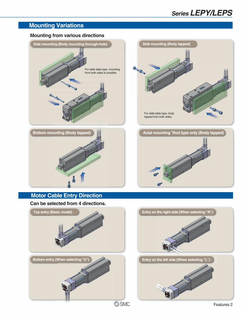
For slide table type, mounting from both sides is possible.
For slide table type, body tapped from both sides.
Side mounting (Body mounting through-hole) Side mounting (Body tapped)
Bottom mounting (Body tapped)
Top entry (Basic model)
Bottom entry (When selecting “U”)
Entry on the right side (When selecting “R”)
Entry on the left side (When selecting “L”)
Axial mounting *Rod type only (Body tapped)
Mounting from various directions
Mounting Variations
Can be selected from 4 directions.
Motor Cable Entry Direction
Features 2

No ProgrammingProgramless type Series LECP1
LECP6
Setting position numberSetting a registered number for the stop positionMaximum 14 points
Moving the actuator to a stop position using FORWARD and REVERSE buttons
Registering the stop position using SET button
1 Setting a stop position2 Registration3
Positionselecting switch
FORWARD and REVERSE buttons
Positionnumberdisplay SET button
Capable of setting up an electric actuator operation without using a PC or teaching box
Speed/Acceleration
16-level adjustment
Speedadjustment switches
Accelerationadjustment switches
Step Motor (Servo/24 VDC)
LECP1
Step Motor (Servo/24 VDC)
Easy Mode for Simple Setting
Example of setting the step data Example of checking the operation status1st screen 1st screen
2nd screen 2nd screen
It can be registered by “SET” after entering the values.
Operation status can be checked.
Simple Setting to Use Straight Away
Start testing
Move for the constant rate
Step data setting
Move jog
<When a PC is used>Controller setting software
P Step data setting, test operation,move jog and move for theconstant rate can be set andoperated on one screen.
Step data input type Series LECP6
If you want to use it right away, select “Easy Mode.”
<When aTB (teaching box) is used>
Teaching box screen
P Simple screen without scrollingpromotes ease of setting andoperating.
P Pick up an icon from the firstscreen to select a function.
P Set up the step dataand check the monitoron the second screen.
P Data can be set withposition and speed. (Otherconditions are already set.)
Offering 2 Types of Controller
Setting of jogand speed of theconstant rate
Data Axis 1Step No. 0
Position 123.45 mm
Speed 100 mm/s
Data Axis 1Step No. 0Position 40.00 mmSpeed 200 mm/s
Monitor Axis 1
Step No. 1
Position 12.34 mm
Speed 10 mm/s
Data Axis 1Step No. 1Position 30.00 mmSpeed 150 mm/s
Features 3

Normal Mode for Detailed SettingSelect normal mode when detailed setting is required.P Step data can be set in detail.P Signals and terminal status can be monitored.
P Parameters can be set.P JOG and constant rate movement, return to origin, test operation
and testing of forced output can be performed.
P Step data setting, parametersetting, monitor, teaching, etc.,are indicated in differentwindows.
Controller setting software<When a PC is used>
<When aTB (teaching box) is used>
Teaching box screen
P Multiple step data can be storedin the teaching box, andtransferred to the controller.
P Continuous test operation by upto 5 step data.
P Each function (step data setting,test, monitor, etc.) can be selectedfrom the main menu.
The actuator and controller are provided as a set. (They can be ordered separately.)
Confirm that the combination of the controller and the actuator is correct.<Check the following before use.>q Check the actuator label for model number. This matches the controller.w Check Parallel I/O configuration matches (NPN or PNP).
ControllerActuator
q w
q
Step data setup window
Parameter setup window
Monitoring windowTeaching window
Menu Axis 1Step No.
0Operation type
Menu Axis 1Step No. 1Position 123.45 mm
Stop Output monitor Axis 1BUSY[ ]SVRE[ ] SETON[ ]
Main menu screen
Step datasetup screen
Test screen
Monitoring screen
Menu Axis 1Step dataParameter Test
Features 4

Item DetailsEasymode
TB PC
Normalmode
TB, PC
Programless typeLECP1
Hold down MANUAL button( ) for uniform sending(speed is specified value)
Press MANUAL button ( )once for sizing operation(speed, sizing amount are specified values)
Function
Setting Items
Number of step data
Operation command (I/O signal)
Completion signal
N Input the numerical value from controller setting software (PC)N Input the numerical value from teaching boxN Input the numerical value from controller setting software (PC)N Input the numerical value from teaching boxN Direct teachingN JOG teaching64 pointsStep No. [IN∗] input ⇒ [DRIVE] input[INP] output
N Select using controller operation buttons
N Direct teachingN JOG teaching
14 pointsStep No. [IN∗] input only[OUT∗] output
Item
Step data “position” setting
Step data and parametersetting
Movement method
Speed
Position
Acceleration/Deceleration
Pushing force
Trigger LV
Pushing speed
Positioning force
Area output
In position
Stroke (+)
Stroke (–)
ORIG direction
ORIG speed
ORIG ACC
JOG
MOVE
Return to ORIG
Test drive
Forced output
DRV mon
In/Out mon
Status
ALM Log record
Save/Load
Language
Step datasetting(Excerpt)
Parametersetting(Excerpt)
Test
Monitor
ALM
File
Other
Selection of “absolute position” and “relative position”
Transfer speed
[Position]: Target position
[Pushing]: Pushing start position
Acceleration/deceleration during movement
Rate of force during pushing operation
Target force during pushing operation
Speed during pushing operation
Force during positioning operation
Conditions for area output signal to turn ON
[Position]: Width to the target position
[Pushing]: How much it moves during pushing
+ side limit of position
– side limit of position
Direction of the return to the original position can be set.
Speed when returning to the original position
Acceleration when returning to the original position
Operation of the specifiedstep data
ON/OFF of the output terminal can be tested.
Alarm currently being generated can be confirmed.
Alarm generated in the past can be confirmed.
Can be changed to Japanese or English.
Set at ABS/INC
Set in units of 1 mm/s
Set in units of 0.01 mm
Set in units of 1 mm/s2
Set in units of 1%
Set in units of 1%
Set in units of 1 mm/s
Set to 100%
Set in units of 0.01 mm
Set to 0.5 mm or more(Units: 0.01 mm)
Set in units of 0.01 mm
Set in units of 0.01 mm
Compatible
Set in units of 1 mm/s
Set in units of 1 mm/s2
Compatible
Compatible
Compatible
Compatible
Compatible
Compatible
Compatible
Compatible
Compatible
×
P
P
P
P
×
×
×
×
×
×
×
×
×
×
P
×
P
P
×
P
×
P
×
×
P
P
P
P
P
P
P
P
P
P
P
×
×
×
×
×
P
P
P
P
×
P
×
P
×
×
P
P
P
P
P
P
P
P
P
P
P
P
P
P
P
P
P
P
P
P
P
P
P
P
P
P
Fixed value (ABS)
Select from 16-level
Direct teaching
JOG teaching
Select from 16-level
Select from 3-level (weak, medium, strong)
No setting required (same value as pushing force)
Fixed value
Fixed value
Fixed value
Fixed value
Fixed value
Compatible
Fixed value
Fixed value
Compatible
Compatible
Compatible (display alarm group)
Continuous operation at theset speed can be tested whilethe switch is being pressed.
Operation at the set distance and speed from the current position can be tested.
Current position, speed, force and thespecified step data can be monitored.
Current ON/OFF status of the inputand output terminal can be monitored.
Step data and parameter can be saved,forwarded and deleted.
P(Continuous
operation)
Series LECP6/LECP1
—
—
—
—
—
—
—
Step datainput type
LECP6
Step data input typeLECP6
Programless typeLECP1
TB: Teaching box PC: Controller setting software
Features 5

System Construction
LECP6LECP1 (Programless type)
Part no.LEC-CN5-mLEC-CK4-m
Power supply for I/O signal 24 VDC
PUSB cable
PC
Communication cable P(3 m)
(A-mini B type)
PTeaching box (Option)
Part no.: LEC-T1-3JGm
with 3 m cable
PController setting kit (Option)
Controller setting kit(Communication cable and USB cable are included.)Part no.: LEC-W1
OrPage 33
Page 32
Controller power supply 24 VDC
P Electric actuator
P Controller
P I/O cable
Motor cable (Fixed) P
Step data input typeLECP6
Controller type
LECP6 (Step data input type)LECP1 (Programless type)
LE-CP-mLE-CP-m
Series LEPY/LEPS
LE-CP-m-SLE-CP-m-S
PActuator cableController type
Pages 31, 40
LECP6(Step data input type)LECP1 (Programless type)
Power supply plug (accessory)
Power supply cable (1.5 m) (accessory)
ConnectionPPower supply connection
Controller type
Pages 28, 40
Page 25 Page 35
Programless typeLECP1
Pages 31, 40
Robotic cableStandard cable
PLC
Series LEPYSeries LEPS
Supplied by customer
Supplied by customer
Page 5
Page 15
Features 6

Size81625
Stroke50, 7550, 100
50, 100, 150
Size81625
Stroke50, 7550, 100
50, 100, 150
Size81625
Stroke50, 7550, 100
50, 100, 150
Size16253240
Stroke100 to 400100 to 600100 to 800200 to 1000
Size162532
Stroke300 to 1000300 to 2000300 to 2000
Ball screw driveSeries LEFS
Size Stroke100 to 600100 to 800200 to 1000
Ball screw driveSeries LEFS
Basic type (R type)Series LESHmR
Symmetrical type (L type)Series LESHmL
In-line motor type (D type)Series LESHmD
Belt driveSeries LEFB
RodType
Size162532
Stroke30 to 30030 to 40030 to 500
Basic typeSeries LEY
Size2532
Stroke30 to 40030 to 500
Basic typeSeries LEY
Size2532
Stroke30 to 40030 to 500
In-line motor typeSeries LEYmD
Size162532
Stroke30 to 20030 to 30030 to 300
Guide rod typeSeries LEYG
Size162532
Stroke30 to 30030 to 40030 to 500
In-line motor typeSeries LEYmD
Size162532
Stroke30 to 20030 to 30030 to 300
Guide rod type/In-line motor typeSeries LEYGmD
Size25
Stroke100 to 1000
Belt driveSeries LEL
Guide Rod Slider
RodType
253240
SMC Electric
SliderType
Slide Table
CAT.NAS100-78
AC Servo Motor (100/200 W)
AC Servo Motor (100/200/400 W)
CAT.NAS100-83
CAT.NAS100-83
CAT.NAS100-87
Step Motor (Servo/24 VDC)
CAT.NAS100-101
Step Motor (Servo/24 VDC) Servo Motor (24 VDC)
Step Motor (Servo/24 VDC) Servo Motor (24 VDC)
Step Motor (Servo/24 VDC) Servo Motor (24 VDC)
Features 7

Control motor
Servo motor(24 VDC)
Control motor
Step motor (Servo/24 VDC)
Size101620253240
Opening/closingstroke
4610142230
Size103050
Rotation angle(°)310, 180, 90
320, 180, 90
Size10162025
Opening/closingstroke
461014
Size10203240
Opening/closingstroke
16 (32)24 (48)32 (64)40 (80)
Size10203240
Opening/closingstroke
46812
Size103050
Rotation angle(°)310, 180, 90
320, 180, 90
Z type (2 fingers)Series LEHZ
Basic typeSeries LER
With dust coverSeries LEHZJ
F type (2 fingers)Series LEHF
S type (3 fingers)Series LEHS
High precision typeSeries LERH
Step data input typefor step motorSeries LECP6
Step data input typefor servo motorSeries LECA6
Control motor
Step motor(Servo/24 VDC)
Programless typeSeries LECP1
Control motor
AC servo motor(100/200 VAC)
AC Servo Motor DriverIncremental typeSeries LECSA
Control motor
AC servo motor(100/200 VAC)
AC Servo Motor DriverAbsolute typeSeries LECSB
Controller
Driver
RotaryTable
Actuators
Miniature
Size610
Stroke
25, 50, 75
Rod typeSeries LEPY
Size610
Stroke
25, 50
Slide table typeSeries LEPS
Gripper Step Motor (Servo/24 VDC)
CAT.NAS100-77
CAT.NAS100-94CAT.NAS100-92
Step Motor (Servo/24 VDC) Step Motor (Servo/24 VDC)
Features 8

Electric Actuators Series LEPY/LEPS
Series Variations
Referencepage
Page 25
Page 35
LECP6
LECP1
Teaching Box
Type
Step datainput type
Controller LEC
Series
LECP6
Compatiblemotor
Step motor(Servo/24 VDC)
Powersupplyvoltage
24 VDC±10%
Input
Parallel input/output
11 inputs(Photo-coupler
isolation)
Output
13 outputs(Photo-coupler
isolation)
Number ofpositioning
pattern points
64
Programlesstype LECP1 Step motor
(Servo/24 VDC)24 VDC±10%
6 inputs(Photo-coupler
isolation)
6 outputs(Photo-coupler
isolation)14
LEPS
LEPY
Referencepage
Page 5
Page 15
Type
Miniaturerod typeLEPY
Miniatureslide table
typeLEPS
Size
6
10
6
10
25, 5075
25, 50
3.14 to 4.5
1.6 to 2.2
5.6 to 11.2
2.8 to 5.6
3.14 to 4.5
1.6 to 2.2
5.6 to 11.2
2.8 to 5.6
—
5.4 to 9.0
2.7 to 4.5
—
5.4 to 9.0
2.7 to 4.5
4
8
5
10
4
8
5
10
Stroke(mm)
Screwlead
Controllerseries
CompactBasic
SeriesLECP6
·SeriesLECP1
10 to 150
20 to 300
10 to 150
20 to 300
10 to 200
20 to 350
10 to 200
20 to 350
—
—
CompactBasic
2.2
1.7
2.2
1.7
—
—
CompactBasic
Pushing force [lbf] Speed(Horizontal)
Max. work load[lb]
(Horizontal)
4.4
3.3
4.4
3.3
Front matter 1

Step Motor (Servo/24 VDC) Type
Electric Actuator/Miniature Rod Type Series LEPYModel Selection ………………………………………………………………………………… Page 1
How to Order ……………………………………………………………………………………… Page 5
Specifications …………………………………………………………………………………… Page 7
Construction ……………………………………………………………………………………… Page 7
Dimensions………………………………………………………………………………………… Page 8
Electric Actuator/Miniature SlideTableType Series LEPSModel Selection ………………………………………………………………………………… Page 10
How to Order ……………………………………………………………………………………… Page 15
Specifications …………………………………………………………………………………… Page 17
Construction ……………………………………………………………………………………… Page 17
Dimensions………………………………………………………………………………………… Page 18
Specific Product Precautions ……………………………………………………………… Page 20
Step Motor (Servo/24 VDC) ControllerStep Data Input Type/Series LECP6 …………………………………………………… Page 25
Controller Setting Kit/LEC-W1 ………………………………………………………… Page 32
Teaching Box/LEC-T1 …………………………………………………………………… Page 33
Programless Controller/Series LECP1 ………………………………………………… Page 35
Front matter 2
LEP
YLE
CP
6LE
CP
1LE
PS
Mod
elS
elec
tion
Ste
pM
otor
(Ser
vo/2
4V
DC
)S
peci
ficP
rodu
ctP
reca
utio
ns

T1
a1 a2
L
Reaches thetarget position
Spe
ed:V
[mm
/s]
Time [s]
T2 T3 T4
1.211.100.990.880.770.660.550.440.330.220.11
03000 50 100 150
Speed [mm/s]
Vert
ical
wor
klo
ad[lb
]
200 250
Step 1 Check the work load–speed. <Speed–Vertical work load graph>
Step 2 Check the cycle time.
• Workpiece mass: 0.44 lbs (0.2kg)
• Speed: 200 [mm/s]
• Acceleration/Deceleration: 3000 [mm/s2]
• Stroke: 40 [mm]
• Workpiece mounting condition: Vertical upward downward transfer
Operatingconditions
Selection Procedure
Positioning Control Selection Procedure
Selection Example
Step 1Check the work load – speed.(Vertical transfer) Step 2 Check the cycle time.
Calculate the cycle time using the following calculation method.Cycle time:T can be found from the following equation.
Select the target model based on the workpiece mass and speed with reference to the <Speed–Vertical work load graph>.Selection example) The LEPY6J is temporarily selected based on the graph shown on the right side.
T = T1 + T2 + T3 + T4 [s]
T4 = 0.2 [s]
T1 = V/a1 [s] T3 = V/a2 [s]
T2 = [s]L – 0.5 · V · (T1 + T3)
V
P T4:Settling time varies depending on the conditions such as motor types, load and in positioning of the step data. Therefore, please calculate the settling time with reference to the following value.
P T2:Constant speed time can be found from the following equation.
P T1:Acceleration time and T3: Deceleration time can be obtained by the following equation.
L : Stroke [mm] ··· (Operating condition)V : Speed [mm/s] ··· (Operating condition)a1: Acceleration [mm/s2] ··· (Operating condition)a2: Deceleration [mm/s2] ··· (Operating condition)
T1: Acceleration time [s]Time until reaching the set speed
T2: Constant speed time [s]Time while the actuator is operating at a constant speed
T3: Deceleration time [s]Time from the beginning of the constant speed operation to stop
T4: Settling time [s]Time until in position is completed
Calculation example)T1 to T4 can be calculated as follows.
T1 = V/a1 = 200/3000 = 0.067 [s], T3 = V/a2 = 200/3000 = 0.067 [s]
T4 = 0.2 [s]
Therefore, the cycle time can be obtained as follows.T = T1 + T2 + T3 + T4 = 0.067 + 0.133 + 0.067 + 0.2 = 0.467 [s]
T2 = = = 0.133 [s]L – 0.5 · V · (T1 + T3)
V
40 – 0.5 · 200 · (0.067 + 0.067)
200
<Speed–Vertical work load graph>(LEPY6/Step motor)∗ It is necessary to mount a guide outside the actuator when using for horizontal transfer.
When selecting the target model, please refer to the horizontal work load and cautions specified in [Specifications] on page 5.
Based on the above calculation result, the LEPY6J-50 is selected.
Electric Actuator/Miniature Rod Type
Series LEPY Model Selection
Lead 4 (LEPY6K)
Lead 8 (LEPY6J)
Step Motor (Servo/24 VDC)
W
1

LE
PY
LE
PS
LE
CP
6L
EC
P1
Mod
elS
elec
tion
Ste
pM
otor
(Ser
vo/2
4V
DC
)S
peci
ficP
rodu
ctP
reca
utio
ns
Duty ratio = A/B x 100 [%]
B
Pushing control
A
Pos
ition
Time
Lead 5 (LEPY10LK)
Lead 10 (LEPY10LJ)
0
2.2
4.4
6.7
9
11
60% 70% 75% 80% 90% 100%
Set value of pushing force [%]
For
ce[lb
f]
Step 1 Check the duty ratio. <Conversion table of pushing force-duty ratio>
Step 2 Check the pushing force. <Force conversion graph>
• Mounting condition: Horizontal (pushing) • Duty ratio: 70 [%]
• Jig weight: 0.44 lbs (0.2 kg) • Speed: 150 [mm/s]
• Pushing force: 6.7lbf (30 N) • Stroke: 40 [mm]
Operatingconditions
Selection Procedure
Pushing Control Selection Procedure
Selection Example
Step 1 Check the duty ratio. Check the lateral load onthe rod end.
Step 2 Check the pushing force.
Select the target model based on the set value of pushing force and pushing forcewith reference to the (Speed–Vertical work load graph).
Selection example)Based on the graph shown on the right side,P Set value of pushing force: 75 [%]P Pushing force: 6.7 lbf (30N)Therefore, the LEPY10LK is temporarily selected.
Step 3 Check the lateral load on the rod end.<Graph of allowable lateral load on the rod end>Confirm the allowable lateral load on the rod end of the actuator: LEPY10L, which has been selected temporarily with reference to the<Graph of allowable lateral load on the rod end>.
Selection example)The jig weight is 1.1 lbs (0.05 kg) ≈ 0.11 lbf (0.5 N) from the table below, so that lateral load on the rod end is allowable.
Select the [Pushing force] from the duty ratio with reference to the <Conversion table of pushing force–duty ratio>.
Selection example)As shown in the below table, the duty ratio is 70 [%],so the set value of pushing force will be = Can be used up to 80 [%]
Step 3
∗ The duty ratio is a ratio at the time that can keep being pushed.
∗ [Set value of pushing force] is one of the step data input to the controller.∗ [Continuous pushing time] is the time that the actuator can continuously keep pushing.
Set value ofpushing force [%]
70 or less
80
100
100
70
50
—
10
5
Duty ratio[%]
Continuouspushing time [minute]
<Force conversion graph>(LEPY10L)
<Conversion table of pushing force–duty ratio>(LEPY10L)
Model
LEPY6 (Basic)
LEPY10 (Basic)
LEPY10L (Compact)
0.11 (0.50)
0.22 (1.0)
0.22 (1.0)
Allowable lateral load on the rod end lbf [N]
<Allowable lateral load on the rod end>
Based on the above calculation result, the LEPY10LK-50 is selected.
2
Model Selection Series LEPY

2.8
2.2
1.7
1.1
0.55
03000 50 100 150
Speed [mm/s]
Wor
klo
ad[lb
]
200 250
1.2
1.1
1.0
0.9
0.8
0.7
0.6
0.4
0.3
0.2
0.1
03000 50 100 150
Speed [mm/s]
Wor
klo
ad[lb
]
200 250
5.5
4.4
3.3
2.2
1.1
03503000 50 100 150
Speed [mm/s]
Wor
klo
ad[lb
]
200 250
5.5
4.4
3.3
2.2
1.1
03503000 50 100 150
Speed [mm/s]
Wor
klo
ad[lb
]
200 250
LEPY6 (Basic)
Horizontal
Speed–Work Load Graph (Guide)
Vertical
LEPY10(L) (Basic/Compact)
Horizontal Vertical
Lead 4 (LEPY6K)
Lead 4 (LEPY6K)
Lead 8 (LEPY6J)
Lead 5 (LEPY10K)
Lead 5 (LEPY10K)
Lead 10 (LEPY10J)
Lead 10 (LEPY10J)
Lead 8 (LEPY6J)
3
Series LEPY

LEP
YLE
PS
LEC
P6
LEC
P1
Mod
elS
elec
tion
Ste
pM
otor
(Ser
vo/2
4V
DC
)S
peci
ficP
rodu
ctP
reca
utio
ns
Allowable Lateral Load on the Rod End
LEPY6 (Basic)
Set value ofpushing force [%]
Duty ratio[%]
Continuous pushingtime [minute]
70
80
100
100
70
50
—
10
5
LEPY10 (Basic)
60 or less
70
100
100
30
15
—
3
1
LEPY10L (Compact)
70 or less
80
100
100
70
50
—
10
5
Model
LEPY6 (Basic)
LEPY10 (Basic)
LEPY10L (Compact)
0.11 (0.50)
0.22 (1.0)
0.22 (1.0)
Allowable lateral load on the rod end lbf [N]
Force Conversion Graph (Guide)
Lead 4 (LEPY6K)
Lead 8 (LEPY6J)
Lead 5 (LEPY10LK)
Lead 10 (LEPY10LJ)
Lead 5 (LEPY10K)
Lead 10 (LEPY10J)
0
1.1
2.2
3.4
4.5
5.6
70% 80% 90% 100%
Set value of pushing force [%]
For
ce[lb
f]
0
2.2
4.5
6.7
9.0
11.2
13.5
50% 60% 70% 80% 90% 100%
Set value of pushing force [%]
For
ce[lb
f]
0
2.2
4.5
6.7
9.0
11.2
60% 70% 80% 90% 100%
Set value of pushing force [%]
For
ce[lb
f]
F
Set value ofpushing force [%]
Duty ratio[%]
Continuous pushingtime [minute]
Set value of pushing force [%]
Duty ratio[%]
Continuous pushingtime [minute]
4
Model Selection Series LEPY

Confirm that the combination of the controller and the actuator is correct.
The actuator and controller are sold as a package. (Controller → Page 25)
<Check the following before use.>q Check the actuator label for model number. This matches the controller.w Check Parallel I/O configuration matches (NPN or PNP).
q w
∗ Refer to the operation manual for using the products. Please download it via our website, http://www.smcworld.com
How to Order
LEPY6, 10Series LEPY
LEPY 10
610
q Size
K 50 11R 6N
U
Nil L
R
Entry on the left side
Entry on the right side
Top entry
Bottom entry
tMotor cable mounting direction
RoHS
Electric ActuatorMiniature Rod Type
Symbol
KJ
Screw lead
48
510
LEPY6 LEPY10
e Lead screw type [mm]Symbol
255075
r Stroke [mm]Stroke
255075
y Actuator cable type∗
NilSR
Without cableStandard cable
Robotic cable (Flexible cable)
Note) CE-compliant productsEMC compliance was tested by combining the electric actuator LEP series andthe controller LEC series. The EMC depends on the configuration of thecustomer’s control panel and the relationship with other electrical equipment andwiring. Therefore conformity to the EMC directive cannot be certified for SMC components incorporated into the customer’s equipment under actual operating conditions. As a result it is necessary for the customer to verify conformity to the EMC directive for the machinery and equipment as a whole.
Caution
SymbolNilL
Motor sizeBasic type
Compact type
wMotor sizeApplicable size
6, 1010
q w e r t y u i o !0
Step Motor (Servo/24 VDC)
∗ The standard cable should be used on fixed parts. For using on moving parts, select the robotic cable.
5

LEP
YLE
PS
LEC
P6
LEC
P1
Mod
elS
elec
tion
Ste
pM
otor
(Ser
vo/2
4V
DC
)S
peci
ficP
rodu
ctP
reca
utio
ns
∗ Produced upon receipt of order (Robotic cable only)Refer to the specifications Note 6) on page 7.
Nil135
Without cable1.535
8ABC
8∗
10∗
15∗
20∗
u Actuator cable length [m]
Nil135
Without cable1.5∗
3∗
5∗
o I/O cable length [m]
∗ Only available for the controller types “6N” and“6P”DIN rail is not included. Order it separately.(Refer to page 26.)
NilD
Screw mountingDIN rail mounting∗
!0 Controller mounting
Nil6N6P1N1P
Without controllerNPNPNPNPNPNP
LECP1(Programless type)
LECP6(Step data input type)
∗ For details about controllers and compatible motors, refer to the compatible controllers below.
i Controller type
Compatible Controllers
Type
Series
Features
Compatible motor
LECP6
24 VDC
Value inputStandard controller
64 points
LECP1
Step motor(Servo/24 VDC)
14 points
Capable of setting up operationwithout using a PC or teaching box
Page 25 Page 35
Step datainput type
Programless type
Maximum number of step data
Power supply voltage
Reference page
∗ When "Without controller" is selected forcontroller types, I/O cable length cannot beselected.
6
Electric Actuator/Miniature Rod Type Series LEPY

!2 ew i!1 t!0
!3 qu r y o !4
Specifications
Construction
Weight
Model LEPY6Stroke [mm]
Product weight [lb] Basic
Model LEPY10Stroke [mm]
Product weight[lb]
Basic
Compact
25
1.04
0.9
50
1.2
1.08
75
1.37
1.3
No. Description Material Note1234567
8
910111213
14
BodyScrew shaftScrew nutRodSpiderHubSocket
Bearing stopper
Motor plateGuide ringBearingBushingSoft wiper
Component Parts
Step motor(Servo/24 VDC)
Aluminum alloyStainless steelStainless steelStainless steel
NBRAluminum alloy
Free cutting carbon steelSize 6: Aluminum alloySize 10: Carbon steel
Aluminum alloyAluminum alloy
—Oil impregnated sintered copper alloy
—
—
AnodizedHeat treatment + Specially treatedHeat treatment + Specially treated
Nickel plated
AnodizedSize 10 only
25
0.5
50
0.6
75
0.7
Model LEPY6 LEPY10Stroke [mm]Screw lead [mm]Pushing force[lbf] Note 1)
Pushing speed [mm/s] Note 5)
Acceleration/Deceleration [mm/s2]Positioning repeatability [mm]Backlash [mm]Impact/Vibration resistance [m/s2] Note 7)
Actuation typeGuide typeMax. operating frequency [c.p.m]Operating temperature rangeOperating humidity range [%RH]Motor sizeMotor typeEncoderRated voltage [V]
Power consumption [W] Note 8)
Standby power consumption when operating [W] Note 9)
Momentary max. powerconsumption [W] Note 10)
Controller weight lb [kg]
BasicCompactBasicCompactBasicCompactBasicCompactBasicCompact
Horizontal
Vertical
Horizontal
Vertical
BasicCompactBasicCompactBasicCompact
25, 50, 75
3000±0.05±0.150/20
Slide screwSliding bushing
6041 to 104°F (5 to 40°C)
90 or less (No condensation)
Step motor (Servo/24 VDC)Incremental A/B phase (800 pulse/rotation)
DC 24 ±10%
0.33 [0.15] (Screw mounting), 0.37 [0.17] (DIN rail mounting)
55.5 to 11.25.4 to 9.0
4.44.43.33.3
10 to 20010 to 20010 to 15010 to 150
10
102.8 to 5.62.7 to 4.5
3.33.32.22.2
20 to 350 Note 4)
20 to 350 Note 4)
20 to 300 Note 4)
20 to 300 Note 4)
20
l20 l28
Max. work load[lb] Note 2) Note 3)
Speed[mm/s] Note 3) Note 6)
43.1 to 4.5
—2.2—1.1—
10 to 150—
10 to 150—10
81.6 to 2.2
—1.6—
0.55—
20 to 300 Note 4)
—20 to 300 Note 4)
—20
12—11—22—
282222165545
Act
uato
rsp
ecifi
catio
nsE
lect
ric
spec
ifica
tions
Note 1) Pushing force accuracy is LEPY6: ±30% (F.S.), LEPY10: ±25% (F.S.).
Refer to page 22 for the detailed setting range and precautions.
The pushing force and the duty ratio are changed by the set value. Check “Force Conversion Graph (Guide)” on page 4 and [14] on page 22.
Note 2) The maximum value of the work load for the positioning operation. An external guide is necessary to support the load.The actual work load and transfer speed are changed by the condition of the external guide.
Note 3) Speed is changed by the work load. Check “Speed–Work Load Graph (Guide)” on page 3.
Note 4) When the stroke is 25 mm, the maximum speed will be 250 mm/sec.
Note 5) Set to the pushing force when pushing.
Note 6) The speed and force may change depending on the cable length, load and mounting conditions.Furthermore, if the cable length exceeds 5 m, then it will decrease by up to 10% for each 5 m. (At15 m: Reduced by up to 20%)
Note 7) Impact resistance: No malfunction occurred when the actuator was tested with a drop tester in both an axial direction and a perpendicular direction to the lead screw. (Test was performed with the actuator in the initial state.)Vibration resistance: No malfunction occurred in a test ranging between 45 to 2000 Hz.Test wasperformed in both an axial direction and a perpendicular direction to the lead screw. (Test wasperformed with the actuator in the initial state.)
Note 8) Power consumption (including the controller) is for when the actuator is operating.Note 9) Standby power consumption when operating (including the controller) is for when the actuator is
stopped in the set position during operation. Except during pushing operation.Note 10) Momentary max. power consumption (including the controller) is for when the actuator is
operating. This value can be used for the selection of the power supply.
7
Series LEPY

LEP
YLE
PS
LEC
P6
LEC
P1
Mod
elS
elec
tion
Ste
pM
otor
(Ser
vo/2
4V
DC
)S
peci
ficP
rodu
ctP
reca
utio
ns
4.5
10 Note 5)
124.5
M4 x 0.7thread depth 7
2 x M4 x 0.7 thread depth 7
3.5
+0.0250ø2.5H9 ( )
depth 2.5
+0.02502.5H9 ( )
depth 2.5
20
3.5
+0.02502.5H9 ( )
depth 2.5
+0.0250ø2.5H9 ( )
depth 2.5
4
[1]
Rod operating range Note 1)
Stroke
1
D
B
C
2 x M4 x 0.7 x 72 x ø3.3 through
19
A
ø12
13
G
F
E
2 x M4 x 0.7 thread depth 5
20.5
(10)10.5
15
30 2110
Note
5)
L2
L1
59.7
10
20
Motor cable mounting direction:Nil (Top entry)
Motor cable mounting direction:R (Entry on the right side)
Motor cable mounting direction: U (Bottom entry)
Motor cable mounting direction:L (Entry on the left side)
Mounting surface
Manual overridescrew
Motor cable length ≈ 3002 x ø5
Origin Note 2)
[Stroke end]
65
Stroke end[Origin] Note 3)
Dimensions
LEPY6
DimensionsModel L1 L2 A B C D E F G
125.6
156.6
188.6
135.6
166.6
198.6
15
22
29
21
45
70
23
30
37
28
52
77
15
22
29
28
52
77
36
60
85
[mm]
LEPY6m-25mLEPY6m-50mLEPY6m-75m
Note 1) Range within which the rod can move when it returns to origin. Make sure a workpiece mounted on the rod does not interfere with the workpieces and facilities around the rod.Note 2) Position after return to origin.Note 3) The number in brackets indicates when the direction of return to origin has changed.Note 4) Do not apply rotational torque to the rod end.Note 5) The direction of rod end width across flats (l10) differs depending on the products.
8
Electric Actuator/Miniature Rod Type Series LEPY

Motor cable mounting direction:Nil (Top entry)
Motor cable mounting direction:R (Entry on the right side)
Motor cable mounting direction:L (Entry on the left side)
Motor cable mounting direction:U (Bottom entry)
+0.0250ø3H9 ( )
depth 3
+0.02503H9 ( )
depth 3
4
28
(14)
7
14.5
185.5
12 Note 5)
M5 x 0.8thread depth 9
2 x M5 x 0.8 thread depth 9
+0.02503H9 ( )
depth 3
4+0.025
0ø3H9 ( )depth 3
5
[1] 1
D ECB2 x M5 x 0.8 x 9
2 x ø4.3 through
22ø
14
J
G
F
19
2 x M5 x 0.8 thread depth 9
28.5
21
42 2812
Note
5)
L2
L1
A
28
12Stroke
Motor cable length ≈ 3002 x ø5
Origin Note 2)
[Stroke end]
Stroke end[Origin] Note 3)
Rod operating range Note 1)
20
20
Mounting surface
Manual override screw
Dimensions
LEPY10
DimensionsModel L1 L2 A B C D E F G J
138
163
198
124
149
184
150
175
210
136
161
196
61.8
47.8
20
24
30
20
24
30
22
43
72
22
43
72
30
34
40
30
34
40
29
50
79
29
50
79
20
24
30
20
24
30
29
50
79
29
50
79
39
60
89
39
60
89
[mm]
LEPY10m-25mLEPY10m-50mLEPY10m-75mLEPY10Lm-25mLEPY10Lm-50mLEPY10Lm-75m
Note 1) Range within which the rod can move when it returns to origin. Make sure a workpiece mounted on the rod does not interfere with the workpieces and facilities around the rod.Note 2) Position after return to origin.Note 3) The number in brackets indicates when the direction of return to origin has changed.Note 4) Do not apply rotational torque to the rod end.Note 5) The direction of rod end width across flats (l12) differs depending on the products.
9
Series LEPY

LEP
YLE
PS
LEC
P6
LEC
P1
Mod
elS
elec
tion
Ste
pM
otor
(Ser
vo/2
4V
DC
)S
peci
ficP
rodu
ctP
reca
utio
ns
T1
a1 a2
L
Reaches thetarget position
Spe
ed:V
[mm
/s]
Time [s]
T2 T3 T4
2.8
2.2
1.6
1.1
0.55
03000 50 100 150
Speed [mm/s]
Wor
klo
ad[lb
]
200 250
15
40
0
80
120
160
200
0 0.44 0.88 1.32 1.76 2.2
Work load [lb]
Ove
rhan
g:L1
[mm
]
Step 3
Step 1 Check the work load–speed. <Speed–Horizontal work load graph>
Step 2 Check the cycle time.
Check the guide allowable moment.
Check the guide allowable moment
• Workpiece mass: 0.55 lb (0.25 kg)
• Speed: 200 [mm/s]
• Acceleration/Deceleration: 3000 [mm/s2]
• Stroke: 20 [mm]
• Workpiece mounting condition: Horizontal transfer
Operatingconditions
Selection Procedure
Positioning Control Selection Procedure
Selection Example
Step 1 Step 2 Check the cycle time. Step 3 Check the guide allowable moment.
Calculate the cycle time using the following calculationmethod.Cycle time: T can be found from the following equation.
Select the target model based on the workpiece mass and speed with reference to the <Speed–Horizontal work load graph>.Selection example) The LEPS6J is temporarily selected based on the graph shown on the right side.
T = T1 + T2 + T3 + T4 [s]
T1 = V/a1 [s]
T4 = 0.2 [s]
T3 = V/a2 [s]
P T4: Settling time varies depending on the conditionssuch as motor types, load and in positioning of the step data. Therefore, please calculate the settling time with reference to the following value.
P T2: Constant speed time can be found from the following equation.
P T1: Acceleration time and T3: Deceleration time can be obtained by the following equation.
L : Stroke [mm] ··· (Operating condition)V : Speed [mm/s] ··· (Operating condition)a1 : Acceleration [mm/s2] ··· (Operating condition)a2 : Deceleration [mm/s2] ··· (Operating condition)
T1: Acceleration time [s] ··· Time until reaching the set speed
T2: Constant speed time [s] ··· Time while the actuator is operating at a constant speed
T3: Deceleration time [s] ··· Time from the beginning of the constant speed operation to stop
T4: Settling time [s] ··· Time until in position is completed
Calculation example)T1 to T4 can be calculated as follows.T1 = V/a1 = 200/3000 = 0.067 [s], T3 = V/a2 = 200/3000 = 0.067 [s]
T4 = 0.2 [s]Therefore, the cycle time can be obtained as follows.T = T1 + T2 + T3 + T4 = 0.067 + 0.033 + 0.067 + 0.2 + 0.367 [s]
T2 = = = 0.033 [s]L – 0.5 · V · (T1 + T3)
V20 – 0.5 · 200 · (0.067 + 0.067)
200
<Speed–Horizontal work load graph>(LEPS6/Step motor)
Based on the above calculation result, the LEPS6J-25 is selected.
Electric Actuator/Miniature Slide Table Type
Series LEPS Model Selection
Lead 4 (LEPS6K)
Lead 8(LEPS6J)
LEPS6 (Basic)
T2 = [s]L – 0.5 · V · (T1 + T3)
V
Step Motor (Servo/24 VDC)
Check the work load – speed.(Horizontal transfer)
10

Duty ratio = A/B x 100 [%]
B
Pushing control
A
Pos
ition
Time
Lead 5 (LEPS10LK)
Lead 10 (LEPS10LJ)
0
2.2
4.5
6.7
9.0
11.2
60% 70% 75% 80% 90% 100%
Set value of pushing force [%]
For
ce[lb
f]
15
0
40
80
120
160
200
0.0 0.88 1.76 2.6 3.5 4.4
Ove
rhan
g:L1
[mm
]
Work load [lb]
Step 1 Check the duty ratio. <Conversion table ofpushing force-duty ratio>
Step 2 Check the pushing force. <Force conversion graph>
• Mounting condition: Horizontal (pushing) • Duty ratio: 70 [%]
• Jig weight: 0.88 lbf (0.4kg) • Speed: 150 [mm/s]
• Pushing force: 6.7 lbf (30 N) • Stroke: 40 [mm]
Operatingconditions
Selection Procedure
Pushing Control Selection Procedure
Selection Example
Step 1 Check the duty ratio. Step 2 Check the pushing force.
Select the target model based on the set value of pushing force and pushing force with reference to the <Speed–Vertical work load graph>.
Selection example)Based on the graph shown on the right side,P Set value of pushing force: 75 [%]P Pushing force: 6.7 lbf (30 N)Therefore, the LEPS10LK is temporarily selected.
Step 3 Check the guide allowable moment.
Select the [Pushing force] from the duty ratio with reference to the<Conversion table of pushing force–duty ratio>.
Selection example)As shown in the below table, the duty ratio is : 70 [%]so the set value of pushing force will be = Can be used up to 80 [%]
Step 3
∗ The duty ratio is a ratio at the time that can keep being pushed.
∗ [Set value of pushing force] is one of the step data input to the controller.∗ [Continuous pushing time] is the time that the actuator can continuously keep pushing.
Set value ofpushing force [%]
70 or less
80
100
100
70
50
—
10
5
Duty ratio(%)
Continuouspushing time [minute]
<Conversion table of pushing force–duty ratio>(LEPS10L)
Based on the above calculation result, the LEPS10LK-50 is selected.
<Force conversion graph>(LEPS10L)
Check the guide allowable moment.
11
Series LEPS

5.5
4.4
3.3
2.2
1.1
03503000 50 100 150
Speed [mm/s]
Wor
klo
ad[lb
]
200 250
5.5
4.4
3.3
2.2
1.1
03503000 50 100 150
Speed [mm/s]
Wor
klo
ad[lb
]
200 250
2.8
2.2
1.7
11
0.6
03000 50 100 150
Speed [mm/s]
Wor
klo
ad[lb
]
200 250
1.21.11.0
0.880.770.660.550.440.330.220.11
03000 50 100 150
Speed [mm/s]
Wor
klo
ad[lb
]
200 250
Speed–Work Load Graph (Guide)
LEPS10(L) (Basic/Compact)
Horizontal Vertical
Lead 5 (LEPS10K)
Lead 5 (LEPS10K)
Lead 10 (LEPS10J)
Lead 10 (LEPS10J)
Force Conversion Graph (Guide)
LEPS6 (Basic)
Set value of pushing force [%] Duty ratio [%] Continuous pushing time [minute]
70
80
100
100
70
50
—
10
5
LEPS10 (Basic)
Set value of pushing force [%] Duty ratio [%] Continuous pushing time [minute]
60 or less
70
100
100
30
15
—
3
1
LEPS10L (Compact)
Set value of pushing force [%] Duty ratio [%] Continuous pushing time [minute]
70 or less
80
100
100
70
50
—
10
5
Lead 4 (LEPS6K)
Lead 8 (LEPS6J)
Lead 5 (LEPS10LK)
Lead 10 (LEPS10LJ)
Lead 5 (LEPS10K)
Lead 10 (LEPS10J)
5.6
4.5
3.4
2.2
1.1
070 80 90 100
Set value of pushing force [%]
For
ce[lb
f]
13.5
11.2
9.0
6.7
4.5
2.2
050 60 70 80 90 100
Set value of pushing force [%]
For
ce[lb
f]
11.2
9.0
6.7
4.5
2.2
060 70 80 90 100
Set value of pushing force [%]
For
ce[lb
f]
LEPS6 (Basic)
Horizontal Vertical
Lead 4 (LEPS6K)Lead 4 (LEPS6K)
Lead 8 (LEPS6J)Lead 8 (LEPS6J)
12
Model Selection Series LEPS
LEP
YLE
PS
LEC
P6
LEC
P1
Mod
elS
elec
tion
Ste
pM
otor
(Ser
vo/2
4V
DC
)S
peci
ficP
rodu
ctP
reca
utio
ns

Work load [lb]
Ove
rhan
g:L1
[mm
]
0 0.44 0.88 0.32 1.76 2.2Work load [lb]
Ove
rhan
g:L1
[mm
]
0
40
80
120
160
200
0
40
80
120
160
200
Work load [lb]
Ove
rhan
g:L1
[mm
]
0.0 0.88 1.76 2.64 3.53 4.40
40
80
120
160
200
Work load [lb]
Ove
rhan
g:L1
[mm
]
0
40
80
120
160
200
Work load [lb]
Ove
rhan
g:L2
[mm
]
Work load [lb]O
verh
ang:
L2[m
m]
0
40
80
120
160
200
Work load [lb]
Ove
rhan
g:L2
[mm
]
0
40
80
120
160
200
Work load [lb]
Ove
rhan
g:L3
[mm
]
Work load [lb]
Ove
rhan
g:L3
[mm
]
0
40
80
120
160
200
0
40
80
120
160
200
Work load [lb]O
verh
ang:
L3[m
m]
0
40
80
120
160
200
Work load [lb]
Ove
rhan
g:L3
[mm
]
0
40
80
120
160
200
Work load [kg]
Ove
rhan
g:L4
[mm
]
Work load [kg]
Ove
rhan
g:L4
[mm
]
0
40
80
120
160
200
Work load [lb]
Ove
rhan
g:L5
[mm
]
0 0.22 0.44 0.66 0.88 1.10
40
80
120
160
200
Work load [lb]
Ove
rhan
g:L5
[mm
]
0 0.66 1.32 1.98 2.65 3.30
40
80
120
160
200
Ove
rhan
g:L6
[mm
]
0
40
80
120
160
200
Ove
rhan
g:L6
[mm
]
0
40
80
120
160
200
0
40
80
120
160
200
Work load [kg]
Ove
rhan
g:L4
[mm
]
0
40
80
120
160
200
Work load [kg]
Ove
rhan
g:L4
[mm
]0
40
80
120
160
200
050
100150200250300
Work load [lb]
Ove
rhan
g:L2
[mm
]
050
100150200250300
L1
L2
L3
L4
L5
L6
0 0.44 0.88 0.32 1.76 2.2 0.0 0.88 1.76 2.64 3.53 4.4
0 0.44 0.88 0.32 1.76 2.2 0 0.44 0.88 0.32 1.76 2.2 0.0 0.88 1.76 2.64 3.53 4.4 0.0 0.88 1.76 2.64 3.53 4.4
0.0 0.88 1.76 2.64 3.53 4.4 0.0 0.88 1.76 2.64 3.53 4.4
0.0 0.88 1.76 2.64 3.53 4.40.0 0.88 1.76 2.64 3.53 4.4
0 0.44 0.88 0.32 1.76 2.2 0 0.44 0.88 0.32 1.76 2.2
0 0.44 0.88 0.32 1.76 2.20 0.44 0.88 0.32 1.76 2.2
Work load [lb]0 0.22 0.44 0.66 0.88 1.1
Work load [lb]0 0.66 1.32 1.98 2.65 3.3
Dynamic Allowable Moment
Load overhanging directionm: Work loadL: Overhang to the work load center of gravity [mm]
Model
LEPS6 LEPS10LEPS6m-25 LEPS6m-50 LEPS10m-25 LEPS10m-50
Hor
izon
talm
ount
ing
Wal
lmou
ntin
g
Note) This graph shows the amount of allowable overhang when the center of gravity of the workpiece overhangs in one direction.
Mou
ntin
gor
ient
atio
n
13
Series LEPS

LE
PY
LE
PS
LE
CP
6L
EC
P1
Mod
elS
elec
tion
Ste
pM
otor
(Ser
vo/2
4V
DC
)Sp
ecific
Prod
uctP
recau
tions
Static Allowable Moment
Allowable moment lbf·ft [N·m]
Pitch moment
Mp
0.79
1.88
Yaw moment
My
0.79
1.88
Roll moment
Mr
1.85
4.03
Model
LEPS6LEPS10
Static Allowable Moment
Stroke (st)
25
0.05 mm or less
50
0.1 mm or less
Travelingparallelism
Table Deflection (Reference Value)
Table displacement due to pitch moment load (marked with the arrow)
Table displacement due to yawmoment load (marked with the arrow)
Table displacement due to rollmoment load (marked with A)
∗ These values are initial guideline values.
F
F
F A
Pitch moment [lbf·ft]
Dis
plac
emen
t[m
m]
Yaw moment [lbf·ft]
Dis
plac
emen
t[m
m]
Roll moment [lbf·ft]
Dis
plac
emen
t[m
m]
0.00
0.05
0.10
0.15
0.20
0.25
0.30
0.00
0.05
0.10
0.15
0.20
0.25
0.30
0 0.15 0.3 0.4 0.6 0.70.00
0.02
0.04
0.06
0.08
0.10
0 0.15 0.3 0.4 0.6 0.0 0.15 0.3 0.4 0.6 0.7
Pitch moment [lbf·ft]
Dis
plac
emen
t[m
m]
Yaw moment [lbf·ft]
Dis
plac
emen
t[m
m]
Roll moment [lbf·ft]
Dis
plac
emen
t[m
m]
0.00
0.05
0.10
0.15
0.20
0.25
0.30
0 0.4 0.74 1.1 1.50.00
0.02
0.04
0.06
0.08
0.10
0.12
0.14
0.16
0 0.22 0.44 0.66 0.88 1.1 0 0.4 0.7 1.1 1.50.00
0.02
0.04
0.06
0.08
LEPS6m-50
LEPS10m-50
LEPS10m-25
LEPS10m-50
LEPS10m-25
LEPS6m-25
LEPS6m-50
LEPS6m-25
LEPS6
LEPS10 LEPS10 LEPS10
LEPS6 LEPS6
14
Model Selection Series LEPS

Confirm that the combination of the controller and the actuator is correct.
The actuator and controller are sold as a package. (Controller → Page 24)
<Check the following before use.>q Check the actuator label for model number. This matches the controller.w Check Parallel I/O configuration matches (NPN or PNP).
q w
∗ Refer to the operation manual for using the products. Please download it via our website, http: //www.smcworld.com
Step Motor (Servo/24 VDC)
How to Order
LEPS6, 10Series LEPS
LEPS 10 K 50 11R 6N
RoHS
Electric ActuatorMiniature Slide Table Type
Note) CE-compliant productsEMC compliance was tested by combining the electric actuator LEP series andthe controller LEC series. The EMC depends on the configuration of thecustomer’s control panel and the relationship with other electrical equipment andwiring. Therefore conformity to the EMC directive cannot be certified for SMC components incorporated into the customer’s equipment under actual operating conditions. As a result it is necessary for the customer to verify conformity to the EMC directive for the machinery and equipment as a whole.
Caution
q w e r t y u i o !0
610
q Size
U
Nil L
R
Entry on the left side
Entry on the right side
Top entry
Bottom entry
tMotor cable mounting direction
Symbol
KJ
Screw lead
48
510
LEPS6 LEPS10
e Lead screw type [mm]Symbol
2550
r Stroke [mm]Stroke
2550
SymbolNilL
Motor sizeBasic type
Compact type
wMotor sizeApplicable size
6, 1010
y Actuator cable type∗
NilSR
Without cableStandard cable
Robotic cable (Flexible cable)
∗ The standard cable should be used on fixed parts. For using on moving parts, select the robotic cable.
15

LE
PY
LE
PS
LE
CP
6L
EC
P1
Mod
elS
elec
tion
Ste
pM
otor
(Ser
vo/2
4V
DC
)S
peci
ficP
rodu
ctP
reca
utio
ns
Nil135
Without cable1.5∗
3∗
5∗
o I/O cable length [m]
∗Only available for the controller types “6N” and “6P”DIN rail is not included. Order it separately.(Refer to page 26.)
NilD
Screw mountingDIN rail mounting∗
!0 Controller mounting
Nil6N6P1N1P
Without controllerNPNPNPNPNPNP
LECP1(Programless type)
LECP6(Step data input type)
∗ For details about controllers and compatible motors, refer to the compatible controllers below.
i Controller typeu Actuator cable length [m]
∗ Produced upon receipt of order (Robotic cable only) Refer to the specifications Note 6) on page 17.
Nil135
Without cable1.535
8ABC
8∗
10∗
15∗
20∗
Compatible Controllers
Type
Series
Features
Compatible motor
LECP6
24 VDC
Value inputStandard controller
64 points
LECP1
Step motor(Servo/24 VDC)
14 points
Capable of setting up operation without using a PC or teaching box
Page 25 Page 35
Step datainput type
Programless type
Max. number of step data
Power supply voltage
Reference page
∗ When “Without controller” is selected forcontroller types, I/O cable length cannot be selected.
16
Series LEPSElectric Actuator/Miniature Slide Table Type

Max. work load[lb] Note 2) Note 3)
Speed[mm/s]
r w!5 !4 !3e u !2
qo y t !0 i !1 !6
Note 3)Note 6)
Specifications
Weight
Model LEPS6Stroke [mm]
Product weight [lb] Basic
Model LEPS10Stroke [mm]
Productweight [lb]
Basic
Compact
25
1.23
1.1
50
1.37
1.30
Construction
Note 1) Pushing force accuracy is LEPS6: ±30% (F.S.), LEPS10: ±25%(F.S.).Refer to page 22 for the detailed setting range and precautions. The pushing force and the duty ratio are changed by the set value. Check “Force Conversion Graph (Gulde)” on page 12 and [14] on page 22.
Note 2) The maximum value of the workload for the positioning operation. Chcek “Dynamic AllowableMoment” graph for the allowable moment of the guide on page 13.
Note 3) Speed is changed by the work load. Check “Speed–Work Load Graph (Guide)” on page 12.Note 4) When the stroke is 25 mm, the maximum speed will be 250 mm/sec.Note 5) Set to the pushing force when pushing.Note 6) The speed and force may change depending on the cable length, load and mounting
conditions. Furthermore, if the cable length exceeds 5 m, then it will decrease by up to 10% for each 5 m. (At 15 m: Reduced by up to 20%)
Model LEPS6 LEPS10Stroke [mm]Screw lead [mm]Pushing force [lbf] Note 1)
Pushing speed [mm/s] Note 5) Note 6)
Acceleration/Deceleration [mm/s2]Positioning repeatability [mm]Backlash [mm]Impact/Vibration resistance [m/s2] Note 7)
Actuation typeGuide typeMax. operating frequency [c.p.m]Operating temperature rangeOperating humidity range [%RH]Motor sizeMotor typeEncoder (Angular displacement sensor)Rated voltage [V]
Power consumption [W] Note 8)
Standby power consumption when operating [W] Note 9)
Momentary max. power consumption [W] Note 10)
Controller weight lbs [kg]
BasicCompactBasicCompactBasicCompactBasicCompactBasicCompact
Horizontal
Vertical
Horizontal
Vertical
BasicCompactBasicCompactBasicCompact
Act
uato
rsp
ecifi
catio
nsE
lect
ric
spec
ifica
tions
25, 50
3000±0.05±0.150/20
Slide screwLinear guide
6041 to 104°F (5 to 40°C)
90 or less (No condensation)
Step motor (Servo/24 VDC)Incremental A/B phase (800 pulse/rotation)
DC 24 ±10%
0.33 (0.15) (Screw mounting), 0.37 (0.17) (DIN rail mounting)
55.6 to 11.25.4 to 9.0
4.44.43.33.3
10 to 20010 to 20010 to 15010 to 150
10
102.8 to 5.62.7 to 4.5
3.33.32.22.2
20 to 350 Note 4)
20 to 350 Note 4)
20 to 300 Note 4)
20 to 300 Note 4)
20
l20 l28
282222165545
No. Description Material Note123456789
10
1112131415
16
BodyScrew shaftScrew nutTableLinear guideRodSpiderHubSocket
Bearing stopper
Motor plateGuide ringBearingBushingSoft wiper
AnodizedHeat treatment + Specially treatedHeat treatment + Specially treated
Anodized
Nickel plated
AnodizedSize 10 only
Component Parts
Step motor(Servo/24 VDC)
25
0.64
50
0.77
Aluminum alloyStainless steelStainless steelAluminum alloy
—Stainless steel
NBRAluminum alloy
Free cutting carbon steelSize 6: Aluminum alloySize 10: Carbon steel
Aluminum alloyAluminum alloy
—Oil impregnated sintered copper alloy
—
—
43.1to 4.5
—2.2—1.1—
10 to 150—
10 to 150—10
81.6 to 2.2
—1.6—
0.55—
20 to 300 Note 4)
—20 to 300 Note 4)
—20
12—11—22—
Note 7) Impact resistance: No malfunction occurred when the actuator was tested with a drop tester inboth an axial direction and a perpendicular direction to the lead screw. (Test was performed with the actuator in the initial state.)Vibration resistance: No malfunction occurred in a test ranging between 45 to 2000 Hz. Test was performed in both an axial direction and a perpendicular direction to the lead screw. (Test was performed with the actuator in the initial state.)
Note 8) Power consumption (including the controller) is for when the actuator is operating.Note 9) Standby power consumption when operating (including the controller) is for when the actuator
is stopped in the set position during operation. Except during pushing operation.Note 10) Momentary max. power consumption (including the controller) is for when the actuator is
operating. This value can be used for the selection of the power supply.
17
Series LEPS

LEP
YLE
PS
LEC
P6
LEC
P1
Mod
elS
elec
tion
Ste
pM
otor
(Ser
vo/2
4V
DC
)S
peci
ficP
rodu
ctP
reca
utio
ns
2.5H9depth 2.5
3.5
ø2.5H9depth 2.5
45.
2
2.5H9depth 2.5
ø2.5H9depth 2.5
3.5
20
3.5
[1] 1
Table operating range Note 1)
DCBA
19
2 x M4 x 0.7 thread depth 8
4 x M4 x 0.7 thread depth 6
1119
J2511
G
F
E
13
2 x M4 x 0.7 thread depth 5
21
11
10.5
(26.
3)14
.7
41
17.3
18
39.5
4 x M4 x 0.7 thread depth 7
L2
L1
59.7DCA B
Stroke
L3
195.
2
20
65
Motor cable length ≈ 3002 x ø5
Stroke end[Origin] Note 3)
Origin Note 2)
[Stroke end]2 x M4 x 0.7 thread depth 82 x ø3.3 through
Motor cable mounting directionNil (Top entry)
20
20
Motor cable mounting directionR (Entry on the right side)
Motor cable mounting directionU (Bottom entry)
Motor cable mounting directionL (Entry on the left side)
Manual override screw
( )+0.0250 ( )+0.025
0
ø2.5H9depth 2.5
( )+0.0250
2.5H9depth 2.5
( )+0.0250
( )+0.0250
( )+0.0250
Dimensions
LEPS6
DimensionsModel L1 L2 L3 A B C D E F G J
127.1
156.6
138.6
169.6
11.5
13
16.5
22
21
45
24.5
30
28
52
16.5
22
28
52
36
60
76.4
107.4
[mm]
LEPS6m-25mLEPS6m-50m
Note 1) Distance within which the table can move when it returns to origin. Make sure a workpiece mounted on the table does not interfere with the workpieces and facilities around the table.
Note 2) Position after return to origin.Note 3) The number in brackets indicates when the direction of return to origin has changed.
18
Series LEPSElectric Actuator/Miniature Slide Table Type

4
3H9depth 3ø3H9
depth 3
3H9depth 3
ø3H9depth 3
45
[1] 1
ø3H9depth 3
4
E
CB
D
22
2 x M5 x 0.8 thread depth 10
10
K2514
1624
4 x M4 x 0.7 thread depth 6
JFG
19
2 x M5 x 0.8 thread depth 9
52.5
21
29
16
14.5
2618
.5
51
4 x M4 x 0.7 thread depth 8
65
L2
L1
AEDB C
14.5
Stroke
2210
Motor cable length ≈ 3002 x ø5
Origin Note 2)
[Stroke end]
Table operating range Note 1)
Stroke end[Origin] Note 3) 2 x M5 x 0.8 thread depth 9
2 x ø4.3 through
Motor cable mounting directionL (Entry on the left side)
Motor cable mounting directionU (Bottom entry)
20
20Motor cable mounting directionNil (Top entry)
Motor cable mounting directionR (Entry on the right side)
2828
3H9depth 3
( )+0.0250
( )+0.0250
( )+0.0250
( )+0.0250
( )+0.0250
( )+0.0250
Manual overridescrew
Dimensions
LEPS10
DimensionsModel L1 L2 A B C D E F G J K
138
163
124
149
152.5
177.5
138.5
163.5
61.8
47.8
20
24
20
24
22
43
22
43
30
34
30
34
29
50
29
50
20
24
20
24
29
50
29
50
39
60
39
60
88.2
113.2
88.2
113.2
[mm]
LEPS10m-25mLEPS10m-50mLEPS10Lm-25mLEPS10Lm-50m
Note 1) Distance within which the table can move when it returns to origin. Make sure a workpiecemounted on the table does not interfere with the workpieces and facilities around the table.
Note 2) Position after return to origin.Note 3) The number in brackets indicates when the direction of return to origin has changed.
19
Series LEPS

LEP
YLE
PS
LEC
P6
LEC
P1
Mod
elS
elec
tion
Ste
pM
otor
(Ser
vo/2
4V
DC
)S
peci
ficP
rodu
ctP
reca
utio
ns
Rod
Socket
fixed
Series LEPY/LEPSSpecific Product Precautions 1Be sure to read before handling. Refer to back cover for Safety Instructions and the Operation Manual for Electric Actuator Precautions.
Please download it via our website, http://www.smcworld.com
Design/Selection
Warning1. Do not apply a load in excess of the operating limit.
A product should be selected based on the maximum load andallowable moment. If the product is used outside of the operating limit, eccentric load applied to the guide will become excessive and have adverse effects such as creating play on the sliding parts of the piston rod, degraded accuracy, operation and shortened product life.
2. Do not use the product in applications where excessive external force or impact force is applied to it. Do not apply impact and vibration outside of the specifications; it may lead to a malfunction.
3. If gravity acts on the workpiece due to vertical mounting, it may drop due to its own weight depending on theconditions when the product is not energized (SVONsignal is OFF) or stopped (EMG is not energized).
4. Power failure may result in a decrease in the pushing force; ensure that safety measures are in place to prevent injury to the operator or damage to the equipment.When the product is used for clamping, the clamping force could be decreased due to power failure, potentially creating a hazardoussituation in which the workpiece is released.
5. This product cannot be used as a stopper. Excessive load acts on the actuator, which adversely affects theoperation and the life.
Mounting
Warning1. Do not drop or hit the actuator to avoid scratching and
denting the mounting surfaces.Even slight deformation can cause the deterioration of accuracy and operation failure.
2. When mounting workpieces or jigs to the rod end, hold theflats of the rod end with a wrench so that the rod does notrotate (Rod type only).When attaching a bolt or workpiece to the end of the rod, hold the flats of the rod end with a wrench (the rod should be fully retracted). Do not apply tightening torque to the rod non-rotating mechanism. The rod is manufactured to precise tolerances, so even a slight deformation may cause a malfunction and damage (Rod type only).
3. When mounting a bolt, workpiece or jig to the rod end, the bolt should be tightened to a torque within the specified range (Rod type only).Tightening to a torque higher than the specified value may cause a malfunction due to deformation of the component, whilstunder-tightening can cause displacement of the mounting position or in extreme conditions detaching of the workpiece. If the bolt isscrewed in more than the maximum depth, the slide screw will bedamaged, leading to operation failure (Rod type only).
Mounting
Warning
4. The angular position of the rod end flats cannot bechanged because the rod has a non-rotating mechanism inside (Rod type only).The angular position of the rod end flats is not specified; it depends on the actuator type (Rod type only).The rod rotates slightly due to the clearance of the non-rotatingmechanism: Install the bolt or workpiece with consideration to the rotation (Rod type only).
5. When attaching the workpiece to the table, hold the table and tighten the bolts to a torque within the specifiedrange (Slide table only).The table is supported by a linear guide, do not apply impact ormoment when mounting the workload.If the bolts are screwed to more than the maximum thread depth, it may lead to a malfunction due to damage of the linear guide or body.
Model
LEPY6LEPY10
M4 x 0.7
M5 x 0.8
1.03
2.21
Bolt
7
9
10
12
Max.tightening
torque [lbf·ft]
Max.screw-in
depth [mm]
Rod end width across flats [mm]
Top mounting
Front mounting
Model
LEPS6LEPS10
M4 x 0.7
M4 x 0.7
1.03
1.03
Bolt
6
6
Max.tightening
torque [lbf·ft]
Max.screw-in
depth [mm]
Model
LEPS6LEPS10
M4 x 0.7
M4 x 0.7
1.03
1.03
Bolt
7
8
Max.tightening
torque [lbf·ft]
Max.screw-in
depth [mm]
20
7. When it is necessary to operate the product by themanual override screw, check the position of the manual override and leave necessary space for access.Do not apply excessive torque to the manual override screw. This maylead to damage and malfunction.
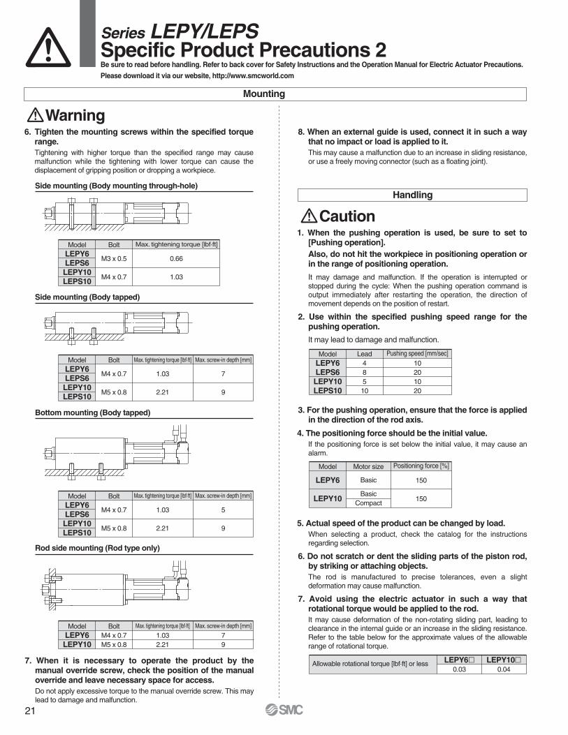
8. When an external guide is used, connect it in such a way that no impact or load is applied to it.This may cause a malfunction due to an increase in sliding resistance, or use a freely moving connector (such as a floating joint).
1. When the pushing operation is used, be sure to set to [Pushing operation].Also, do not hit the workpiece in positioning operation or in the range of positioning operation.
It may damage and malfunction. If the operation is interrupted orstopped during the cycle: When the pushing operation command is output immediately after restarting the operation, the direction ofmovement depends on the position of restart.
2. Use within the specified pushing speed range for thepushing operation.
It may lead to damage and malfunction.
3. For the pushing operation, ensure that the force is applied in the direction of the rod axis.
4. The positioning force should be the initial value.If the positioning force is set below the initial value, it may cause analarm.
5. Actual speed of the product can be changed by load.When selecting a product, check the catalog for the instructionsregarding selection.
6. Do not scratch or dent the sliding parts of the piston rod, by striking or attaching objects.The rod is manufactured to precise tolerances, even a slightdeformation may cause malfunction.
7. Avoid using the electric actuator in such a way that rotational torque would be applied to the rod.It may cause deformation of the non-rotating sliding part, leading to clearance in the internal guide or an increase in the sliding resistance. Refer to the table below for the approximate values of the allowable range of rotational torque.
Handling
Caution
Mounting
Warning
Side mounting (Body mounting through-hole)
Side mounting (Body tapped)
Bottom mounting (Body tapped)
Rod side mounting (Rod type only)
ModelLEPY6LEPS6LEPY10LEPS10
M4 x 0.7
M5 x 0.8
1.03
2.21
Bolt
7
9
Max. tightening torque [lbf·ft] Max. screw-in depth [mm]
ModelLEPY6LEPS6LEPY10LEPS10
M4 x 0.7
M5 x 0.8
1.03
2.21
Bolt
5
9
Max. tightening torque [lbf·ft] Max. screw-in depth [mm]
ModelLEPY6LEPY10
M4 x 0.7M5 x 0.8
1.032.21
Bolt79
Max. tightening torque [lbf·ft] Max. screw-in depth [mm]
ModelLEPY6LEPS6LEPY10LEPS10
M3 x 0.5
M4 x 0.7
0.66
1.03
Bolt Max. tightening torque [lbf·ft]
ModelLEPY6LEPS6LEPY10LEPS10
48510
10201020
Lead Pushing speed [mm/sec]
Model
LEPY6
LEPY10
Basic
BasicCompact
150
150
Motor size Positioning force [%]
Allowable rotational torque [lbf·ft] or less0.03 0.04
LEPY6l LEPY10l
6. Tighten the mounting screws within the specified torque range.Tightening with higher torque than the specified range may cause malfunction while the tightening with lower torque can cause thedisplacement of gripping position or dropping a workpiece.
Series LEPY/LEPSSpecific Product Precautions 2Be sure to read before handling. Refer to back cover for Safety Instructions and the Operation Manual for Electric Actuator Precautions.
Please download it via our website, http://www.smcworld.com
21

LE
PY
LE
PS
LE
CP
6L
EC
P1
Mod
elS
elec
tion
Ste
pM
otor
(Ser
vo/2
4V
DC
)S
peci
ficP
rodu
ctP
reca
utio
ns
Handling
Caution13. In pushing operation, set the product to a position of at
least 0.5 mm away from a workpiece. (This position isreferred to as a pushing start position.)The following alarms may be generated and operation may become unstable.
a. “Posn failed” alarm is generated.The product cannot reach a pushing start position due tovariation in the width of workpieces.
b. “Pushing ALM” alarm is generated.The product is pushed back from a pushing start position after starting to push.
c. “Deviation over flow” alarm is generated.Displacement exceeding the specified value is generated at the pushing operation start position.
14. When pushing operating, operate within duty ratio range.The duty ratio is a ratio at the time that can keep being pushed.
Maintenance
Warning1. Ensure that the power supply is stopped and the
workpiece is removed before starting maintenance workor replacement of the product.
8. Do not operate by fixing the piston rod and moving the actuator body Excessive load will be applied to the rod,leading to damage to the actuator and reduced lifetime.
9. Return to origin1) Do not apply a load, impact or resistance in addition to the
transferred load during return to origin.Additional force will cause the displacement of the origin positionsince it is based on detected motor torque.
2) When the return to origin is set with <Basic parameter> [Origin offset], it is necessary to change the current position of the product. Recheck the value of step data.
3) It is recommended to set the directions of return to origin and pushingin the same direction in order to enhance the measurement accuracyduring pushing operation.
10. There is no backlash effect in pushing operation.The return to origin is done by the pushing operation.The position can be displaced by the effect of the backlash during thepositioning operation.Take the backlash into consideration when setting the position.
11. Do not hit the stroke end except for during the return to origin.This may damage the inner parts.
12. INP output signal1) Positioning operation
When the product comes within the set range by step data [In position], the INP output signal will be turned on.Initial value: Set to [0.50] or higher.
2) Pushing operationWhen the effective pushing force exceeds the step data (trigger LV), the INP (In position) output signal is outputted.When [pushing force] setting and [trigger LV] are set below [pushing force], use the product within the specified range of [pushing force and trigger LV].
a) To ensure that the product pushes the workpiece with the set [pushing force], it is recommended that the [Trigger LV] is set to the same value as the [pushing force].
b) If the [trigger LV] is set lower than the [operation pushingforce (current pushing force) for the pushing operation], thepushing force will exceed the trigger LV from the pushing start position and the INP output signal will be outputted before pushing the workpiece. Increase the pushing force, orchange the workload so that the current pushing force becomes smaller than the Trigger LV.
<Pushing force and trigger LV range>
<Backlash>Model
LEPY6LEPS6LEPY10LEPS10
±0.1±0.1±0.1±0.1
Backlash [mm]
Model
LEPY6LEPS6LEPY10LEPS10
Basic
BasicCompact
70 to 100
50 to 10060 to 100
Motor size Set value of pushing force [%]
Model
LEPY6LEPS6
Basic7080100
Motor sizeSet value of
pushing force [%]1007050
Duty ratio [%]
—105
Continuous pushingtime [minute]
Model
LEPY10LEPS10
Basic60 or less
70100
Motor size
1003015
Duty ratio [%]
—31
Model
LEPY10LEPS10
Compact70 or less
80100
Motor size
1007050
Duty ratio [%]
—105
Series LEPY/LEPSSpecific Product Precautions 3Be sure to read before handling. Refer to back cover for Safety Instructions and the Operation Manual for Electric Actuator Precautions.
Please download it via our website, http://www.smcworld.com
Set value ofpushing force [%]
Set value ofpushing force [%]
Continuous pushingtime [minute]
Continuous pushingtime [minute]
22

Mod
elS
elec
tion
Ste
pM
otor
(Ser
vo/2
4V
DC
)S
peci
ficP
rodu
ctP
reca
utio
ns
Series LECP6
Step Motor(Servo/24 VDC)
Page 25
Page 35
Controller
Step data input type
Programless type
Series LECP1
Step Motor(Servo/24 VDC)
24

Confirm that the combination of the controller and the actuator is correct.
The controller is sold as single unit after the compatible actuator is set.
<Check the following before use.>q Check the actuator label for model number.This matches the controller.w Check Parallel I/O configuration matches (NPN or PNP).
q w
How to Order
Specifications
LE C P 6 N
Series LECP6
Controller (Step data input type)Step Motor (Servo/24 VDC)
P Step motor(Servo/24 VDC)
6 64
Number of step data (Points)
NP
NPNPNP
Parallel I/O type
Nil135
Without cable1.535
I/O cable length [m]NilD Note)
Screw mountingDIN rail mounting
Option
Actuator part number
Compatible motor
Controller(Except cable specifications and actuator options)Example: Enter “LEPY10K-50” for the LEPY10K-50U-R16NI.
Step motor (Servo/24 VDC)
11 inputs (Photo-coupler isolation)13 outputs (Photo-coupler isolation)
Incremental A/B phase (800 pulse/rotation)RS485 (Modbus protocol compliant)
EEPROMLED (Green/Red) one of each
Forced-lock release terminal Note 3)
I/O cable: 5 or less Actuator cable: 20 or lessNatural air cooling
32 to 104°F (0 to 40°C) (No freezing)90 or less (No condensation)
14 to 140°F (–10 to 60°C) (No freezing)90 or less (No condensation)
Power voltage: 24 VDC ±10% Current consumption: 3 A (Peak 5 A) Note 2)
[Including motor drive power, control power, stop, lock release]
5.3 oz (150 g) (Screw mounting)6.0oz (170 g) (DIN rail mounting)
Between the housing (radiation fin) and SG terminal50 (500 VDC)
Note) DIN rail is not included. Order it separately.
∗ When controller equipped type (-l6Nl/-l6Pl) is selected when ordering the LE series, you do not need to order this controller.
Basic SpecificationsItem Specifications
Compatible motor
Power supply Note 1)
Parallel inputParallel outputCompatible encoderSerial communicationMemoryLED indicatorLock controlCable length [m]Cooling systemOperating temperature rangeOperating humidity range [%RH]Storage temperature rangeStorage humidity range [%RH]
Insulation resistance[MΩ]
Weight [g]
RoHS
∗ Refer to the operation manual for using the products. Please download it via our website, http://www.smcworld.com
Note 1) Do not use the power supply of “inrush current prevention type” for the controller power supply.Note 2) The power consumption changes depending on the actuator model. Refer to the specifications of actuator for more details.Note 3) Applicable to non-magnetizing lock.
25

Mod
elS
elec
tion
Ste
pM
otor
(Ser
vo/2
4V
DC
)S
peci
ficP
rodu
ctP
reca
utio
ns
How to Mount
a) Screw mounting (LECP6ll-l)(Installation with two M4 screws)
b) DIN rail mounting (LECP6llD-l)(Installation with the DIN rail)
Ground wire
DIN rail
DIN rail is locked.
Mounting direction
Mounting direction
Ground wire Groundwire
Hook the controller on the DIN rail and press the lever of section A in the arrow direction to lock it.
DIN railAXT100-DR-l
DIN rail mounting adapterLEC-D0 (with 2 mounting screws)
This should be used when the DIN rail mounting adapter is mounted onto the screw mounting type controller afterwards.
∗ For l, enter a number from the “No.” line in the table below. Refer to the dimensions on page 27 for the mounting dimensions.
40
510.5
39
498
38
485.5
37
473
36
460.5
35
448
34
435.5
33
423
32
410.5
31
398
30
385.5
29
373
28
360.5
27
348
26
335.5
25
323
24
310.5
23
298
22
285.5
21
273
No.
L
20
260.5
19
248
18
235.5
17
223
16
210.5
15
198
14
185.5
13
173
12
160.5
11
148
10
135.5
9
123
8
110.5
7
98
6
85.5
5
73
4
60.5
3
48
2
35.5
1
23
No.
L
L Dimension [mm]
7.5
(25)
(35)
A
DIN rail mounting adapter
L5.
5
5.2512.5(Pitch)
1.25
26
Controller (Step data input type)/Step Motor (Servo/24 VDC) Series LECP6

31
150
132
4.6for bodymounting
35
141
166
(81.7)
ø4.5for bodymounting
Power supply LED (Green)(ON: Power supply is ON.)
CN5 parallel I/O connector
CN4 serial I/O connector
CN3 encoder connector
CN2 motor power connector
CN1 power supply connector
Power supply LED (Red)(ON: Alarm is ON.)
31
35
132
64.2
35
150
167.
3(W
hen
lock
ing
DIN
rail)
173.
2(W
hen
rem
ovin
gD
INra
il)
1
66
(81.7)
(91.7)
(11.5)Refer to page 26 for L dimension and
part number of DIN rail.
Dimensions
a) Screw mounting (LECP6ll-l)
b) DIN rail mounting (LECP6llD-l)
27
Series LECP6

Mod
elS
elec
tion
Ste
pM
otor
(Ser
vo/2
4V
DC
)Sp
ecific
Prod
uctP
recau
tions
COM+
COM–
IN0
IN1
IN2
IN3
IN4
IN5
SETUP
HOLD
DRIVE
RESET
SVON
OUT0
OUT1
OUT2
OUT3
OUT4
OUT5
BUSY
AREA
SETON
INP
SVRE
∗ESTOP
∗ALARM
CN5
A1
A2
A3
A4
A5
A6
A7
A8
A9
A10
A11
A12
A13
B1
B2
B3
B4
B5
B6
B7
B8
B9
B10
B11
B12
B13
Power supply 24 VDCfor I/O signal
Load
COM+
COM–
IN0
IN1
IN2
IN3
IN4
IN5
SETUP
HOLD
DRIVE
RESET
SVON
OUT0
OUT1
OUT2
OUT3
OUT4
OUT5
BUSY
AREA
SETON
INP
SVRE
∗ESTOP
∗ALARM
A1
A2
A3
A4
A5
A6
A7
A8
A9
A10
A11
A12
A13
B1
B2
B3
B4
B5
B6
B7
B8
B9
B10
B11
B12
B13
CN5Power supply 24 VDC
for I/O signal
Load
Wiring Example 1
Power Supply Connector: CN1
Wiring Example 2
Parallel I/O Connector: CN5
CN1 Power Supply Connector Terminal for LECP6 (PHOENIX CONTACT FK-MC0.5/5-ST-2.5)
Wiring diagramLECP6Nll-l (NPN) LECP6Pll-l (PNP)
Terminal name Function Details
0V
M24VC24VEMG
BK RLS
Common supply (–)
Motor power supply (+)Control power supply (+)
Stop (+)Lock release (+)
Motor power supply (+) supplied to the controllerControl power supply (+) supplied to the controllerInput (+) for releasing the stopInput (+) for releasing the lock
Input SignalName DetailsCOM+COM–
IN0 to IN5
SETUPHOLDDRIVERESETSVON
Connects the power supply 24 V for input/output signalConnects the power supply 0 V for input/output signal
Instruction to return to the original positionOperation is temporarily stopped
Instruction to driveAlarm reset and operation interruption
Servo ON instruction
Step data specified Bit No.(Input is instructed in the combination of IN0 to 5.)
Output SignalName Details
OUT0 to OUT5BUSYAREA
SETON
INP
SVRE∗ESTOP Note)
∗ALARM Note)
Outputs the step data no. during operationOutputs when the actuator is moving
Outputs within the step data area output setting rangeOutputs when returning to the original position
Outputs when servo is onNot output when EMG stop is instructed
Not output when alarm is generated
Outputs when target position or target force is reached(Turns on when the positioning or pushing is completed.)
∗ When you connect a PLC, etc., to the CN5 parallel I/O connector, please use the I/O cable (LEC-CN5-l).∗ The wiring should be changed depending on the type of the parallel I/O (NPN or PNP).
M24V terminal/C24V terminal/EMG terminal/BK RLS terminal are common (–).
Note) Signal of negative-logic circuit (N.C.)
Power supply plug for LECP6
0VM
24V
C24
VE
MG
BK
RLS
∗ Power supply plug is an accessory.
28
Controller (Step data input type)/Step Motor (Servo/24 VDC) Series LECP6

1. Step data setting for positioning 2. Step data setting for pushingIn this setting, the actuator moves toward and stops at the target position. The following diagram shows the setting items and opera-tion. The setting items and set values for this operation are stated below.
The actuator moves toward the pushing start position, and when it reaches that position, it starts pushing with less than the set force. The following diagram shows the setting items and operation. The setting items and set values for this operation are stated below.
Speed
Speed
Pushing speed
Force
Trigger LV
INP output OFF
Position
Pushing force
ONON
Speed
Speed
INP output OFF
In position
ONON
Position
Step Data Setting
Acceleration Deceleration Acceleration Deceleration
In position
Step Data (Positioning)
: Need to be set.: Need to be adjusted as required.: Setting is not required.
ItemNecessity Details
Movement method
In position
Area 1, Area 2
Positioning force
Trigger LV
Pushing speed
Pushing force
Deceleration
Acceleration
Speed
Position
When the absolute position is required, set Absolute. When the relative position isrequired, set Relative.
Set 0.(If values 1 to 100 are set, the operation will be changed to the pushing operation.)
Max. torque during the positioning operation(No specific change is required.)
Transfer speed to the target position
Setting is not required.
Condition that turns on the AREA outputsignal.
Setting is not required.
Target position
Parameter which defines how rapidly theactuator reaches the speed set. The higher the set value, the faster it reaches the speed set.
Parameter which defines how rapidly theactuator comes to stop. The higher the set value, the quicker it stops.
Condition that turns on the INP output signal.When the actuator enters the range of [inposition], the INP output signal turns on. (It isunnecessary to change this from the initialvalue.) When it is necessary to output the arrival signal before the operation iscompleted, make the value larger.
Step Data (Pushing): Need to be set.: Need to be adjusted as required.
Item Details
Movement method
In position
Area 1, Area 2
Positioning force
Pushing speed
Trigger LV
Pushing force
Deceleration
Acceleration
Speed
Position
When the absolute position is required, set Absolute. When the relative position is required, set Relative.
Max. torque during the positioning operation (No specific change is required.)
Transfer speed to the pushing start position
Condition that turns on the AREA output signal.
Pushing start position
Parameter which defines how rapidly theactuator reaches the speed set. The higher the set value, the faster it reaches the speed set.
Parameter which defines how rapidly theactuator comes to stop. The higher the set value, the quicker it stops.
Condition that turns on the INP output signal. The INP output signal is turned on when the generated force exceeds the value.Threshold level should be less than thepushing force.
Pushing force ratio is defined.The setting range differs depending on the electric actuator type. Refer to the operation manual for the electric actuator.
Pushing speedWhen the speed is set fast, the electric actuator and work pieces might be damaged due to the impact when they hit the end, so this set value should be smaller. Refer to the operation manual of the electric actuator.
Transfer distance during pushing. If thetransferred distance exceeds the setting, itstops even if it is not pushing. If the transfer distance is exceeded, the INP output signal will not be turned on.
Necessity
29
Series LECP6

Mod
elS
elec
tion
Ste
pM
otor
(Ser
vo/2
4V
DC
)S
peci
ficP
rodu
ctP
reca
utio
ns
Power supply
SVON
SETUP
BUSY
SVRE
SETON
INP
∗ALARM
∗ESTOP
Input
Output
Speed
Return to origin
24 V0 V
ONOFF
0 mm/s
ONOFF
IN
DRIVE
OUT
BUSY
INP
Input
Output
SpeedPositioning operation
ONOFF
0 mm/s
ONOFF
“∗ALARM” and “∗ESTOP” are expressed as negative-logic circuit.
∗ When the actuator is in the positioning range in the pushing operation, it does not stop even if HOLD signal is input. “∗ALARM” is expressed as negative-logic circuit.
∗ “OUT” is output when “DRIVE” is changed from ON to OFF.(When power supply is applied, “DRIVE” or “RESET” is turned ON or “∗ESTOP” isturned OFF, all of the “OUT” outputs are turned OFF.)
Scan the stepdata no.
Output the step data no.
HOLD
BUSY
Input
Output
SpeedHOLD during the operation
ONOFF
0 mm/s
ONOFF
IN
DRIVE
OUT
BUSY
INP
Input
Output
SpeedPushing operation
ONOFF
0 mm/s
ONOFF
Scan the stepdata no.
Output the step data no.
Slow-downstartingpoint
RESET
OUT
∗ALARM
Input
Output
ONOFF
ONOFF
ONOFF
Alarm out
Alarm reset
It is possible to identify the alarm group by the combination of OUT signals when the alarm is generated.
15 msor more
15 msor more
If the current pushing force exceeds the “trigger LV” valueof the step data, the INP signal will be turned ON.
If the actuator is within the “in position” range of the step data, INP will be turned ON, but if not, it will remain OFF.
If the actuator is within the “in position” range of the basic parameter, INP will be turned ON, but if not, it will remain OFF.
SignalTiming
Return to Origin
Positioning Operation
HOLD Reset
Pushing Operation
30
Controller (Step data input type)/Step Motor (Servo/24 VDC) Series LECP6

(17.
7)(1
7.7)
(30.7)Connector A
L (11)
(30.7) L (11)
(14.2) (Terminal no.)
(14)
(18)
(14.2)
(14)
(18)
A1 B1
A6 B6
1 25 6
1 2
15 16
(ø8)(Terminal no.)
Connector C
Connector A
(ø5.
5)(ø
6.3)
(Terminal no.)
1 25 6
1 2
15 16
Controller side
A1 B1
A6 B6
(Terminal no.)
Actuator side
Actuator side
Controller side
(13.5)
(10)Connector D
Connector C
Connector D(14.7)
(13.5)
(10)
(14.7)
(22.
4)
(14.4) L
B1 A1
B13 A13
A1
B13
A13B1
Controller side PLC side
(ø8.
9)(Terminal no.)
Actuator cable[Robotic cable, standard cable for step motor (servo/24 VDC)]
Options: Actuator Cable, I/O Cable
I/O cable
LE CP 1
Cable length(L)[m]1358ABC
1.5358∗
10∗
15∗
20∗
Connector Aterminal no.
B-1A-1B-2A-2B-3A-3
AABB
COM-A/COMCOM-B/—
B-4A-4B-5A-5B-6A-6
VccGND
AABB
Signal Cable color
BrownRed
OrangeYellowGreenBlue
BrownBlackRedBlack
OrangeBlack
—
Connector Cterminal no.
Cable color Connector Dterminal no.
216534
121376983
LE-CP- /Cable length: 1.5 m, 3 m, 5 m135
LE-CP- /Cable length: 8 m, 10 m, 15 m, 20 m(∗ Produced upon receipt of order)
8A
BC
∗ Produced upon receipt of order(Robotic cable only)
Cable type
Shield
Nil
S
Robotic cable (Flexible cable)
Standard cable
LEC CN5 1
Cable length(L)[m]135
1.535
∗ Conductor size: AWG28A1
Light brownLight brown
YellowYellow
Light greenLight green
GrayGrayWhiteWhite
Light brownLight brownYellow
BlackRed
BlackRed
BlackRed
BlackRed
BlackRed
BlackRed
Black
Dotcolor
Dotmark
Insulationcolor
Connectorpin no.
A2A3A4A5A6A7A8A9A10A11A12A13
—
YellowLight greenLight green
GrayGrayWhiteWhite
Light brownLight brown
YellowYellow
Light green Light green
RedBlackRed
BlackRed
BlackRed
BlackRed
BlackRed
BlackRed
Shield
Dotcolor
Dotmark
Insulationcolor
Connectorpin no.
B1B2B3B4B5B6B7B8B9B10B11B12B13
31
Series LECP6

Mod
elS
elec
tion
Ste
pM
otor
(Ser
vo/2
4V
DC
)S
peci
ficP
rodu
ctP
reca
utio
ns
PC
q Controller setting software
w Communication cable
e USB cable(A-mini B type)
HRS
How to Order
Contents
q Controller setting software (CD-ROM)
w Communication cable
e USB cable(Cable between the PC and the conversion unit)
Hardware Requirements
PC/AT compatible machine installed with Windows XP and equipped with USB1.1 or USB2.0 ports.
Screen Example
Easy mode screen example Normal mode screen example
LEC W1Controller setting kit
(Japanese and English are available.)
∗ Windows® and Windows XP® are registered trademarks of Microsoft Corporation.
Easy operation and simple settingP Allowing to set and display actuator step data
such as position, speed, force, etc.P Setting of step data and testing of the drive can
be performed on the same page.P Can be used to jog and move at a constant rate.
Detailed settingP Step data can be set in detail.P Signals and terminal status can be monitored.P Parameters can be set.P JOG and constant rate movement, return to origin, test operation and
testing of forced output can be performed.
Series LECController Setting Kit/LEC-W1
32

How to Order
Specifications
LEC T1 3 J GEnable switch
SNoneEquipped with enable switch
NilTeaching box
Cable length [m]3 3
Stop switchG Equipped with stop switch
Initial languageJE
JapaneseEnglish
Item
Stop switch, Enable switch (Option)
3
IP64 (Except connector)
41 to 122°F (5 to 50°C)
90 or less (No condensation)
12.3 oz (350 g) (Except cable)
Description
Switch
Cable length [m]
Enclosure
Operating temperature range
Operating humidity range [%RH]
Weight
Standard functions• Chinese character display• Stop switch is provided.
Option• Enable switch is provided.
∗ Interlock switch for jog and test function
Enable switch(Option)
Stop switch
Easy Mode
Note) CE-complianceThe EMC compliance of the teaching box was tested with the LECP6 series step motor controller (servo/24 VDC) and an applicable actuator.
RoHS
Series LECTeaching Box/LEC-T1
Function
Step data
Jog
Test
Monitor
ALM
TB setting
Details
• Jog operation• Return to origin
• Setting of step data
• 1 step operation• Return to origin
• Display of axis and step data no.• Display of two items selected from Position, Speed, Force.
• Active alarm display• Alarm reset
• Reconnection of axis• Setting of easy/normal mode• Setting of step data and selection
of items from easy mode monitor
MenuDataMonitorJogTestALMTB setting
JogReturn to originJog operation
Test1 step operation
ALMActive alarm displayAlarm reset
TB settingReconnectEasy/NormalSet item
DataStep data no.Setting of two items selected below(Position, Speed, Force, Acceleration, Deceleration)
MonitorDisplay of step no.Display of two items selected below(Position, Speed, Force)
Menu Operations Flowchart
33

Ste
pM
otor
(Ser
vo/2
4V
DC
)M
odel
Sel
ectio
nS
peci
ficP
rodu
ctP
reca
utio
ns
185
1024
25 22.5
34.5w
q
r
t
y e
iu
Dimensions
No.
1
2
3
4
5
6
7
8
LCD
Ring
Stop switch
Stop switch guard
Enable switch(Option)
Key switch
Cable
Connector
A screen of liquid crystal display (with backlight)
A ring for hanging the teaching box
A guard for the stop switch
Switch for each input
Length: 3 meters
A connector connected to CN4 of the controller
When switch is pushed in, the switch locks and stops.The lock is released when it is turned to the right.
FunctionDescription
Prevents unintentional operation (unexpected operation) of the jog test function. Other functions such as data change are not covered.
Function
Step data
Parameter
Test
Monitor
ALM
File
TB setting
Reconnect
Details
• Step data setting
• Parameters setting
• Jog operation/Constant ratemovement
• Return to origin• Test drive
(Specify a maximum of 5 step data and operate.)
• Forced output(Forced signal output, Forced terminal output)
• Drive monitor• Output signal monitor• Input signal monitor• Output terminal monitor• Input terminal monitor
• Active alarm display(Alarm reset)
• Alarm log record display
• Data savingSave the step data and parameters of the controller which is being used for communication (it is possible to save four files, with oneset of step data and parameters defined as one file).
• Load to controllerLoads the data which is saved inthe teaching box to the controllerwhich is being used forcommunication.
• Delete the saved data.
• Display setting(Easy/Normal mode)
• Language setting(Japanese/English)
• Backlight setting• LCD contrast setting• Beep sound setting• Max. connection axis• Distance unit (mm/inch)
• Reconnection of axis
MenuStep dataParameterMonitorTestALMFileTB settingReconnect
Step dataStep data no.Movement methodSpeedPositionAccelerationDecelerationPushing forceTrigger LVPushing speedPositioning forceArea 1, 2In position
ParameterBasicORIG
DRV monitorPosition, Speed, TorqueStep no.Last step no.
StatusActive alarm displayAlarm reset
ALM Log record displayLog entry display
MonitorDriveOutput signalInput signalOutput terminal Input terminal
TestJOG/MOVEReturn to ORIGTest driveForced output
ALMStatusALM Log record
TB settingEasy/NormalLanguageBacklightLCD contrastBeepMax. connection axisPasswordDistance unit
Reconnect
Basic setting
ORIG setting
Output signal monitor
Input signal monitor
Output terminal monitor
Input terminal monitor
FileData savingLoad to controllerFile deletion
Menu Operations Flowchart
Teaching Box Series LEC
34
Normal Mode

How to Order
C 1LE N 1PController
Compatible motorP Step motor (Servo/24 VDC)
Number of step data (Points)1 14 (Programless) Parallel I/O type
NP
NPNPNP
I/O cable length [m]Nil135
Without cable1.535
Actuator part number(Except cable specifications and actuator options)Example: Enter “LEPY10K-50” for the LEPY10K-50U-R16NI.
∗ When controller equipped type (-m1Nm/-m1Pm) isselected when ordering the LE series, you do not need to order this controller.
LEPY10-50
Programless Controller
Series LECP1
Confirm that the combination of the controller and the actuator is correct.
The controller is sold as single unit after the compatible actuator is set.
Specifications
RoHS
Note 1) Do not use the power supply of “inrush current prevention type” for the controller input power supply.Note 2) The power consumption changes depending on the actuator model. Refer to the each actuator’s operation manual etc. for details.Note 3) “10” to “15” in decimal number are displayed as follows in the 7-segment LED.
Note 4) Applicable to non-magnetizing lock.
Decimal display
Hexadecimal display
10
A
11
b
12
c
13
d
14
E
15
F
∗ Refer to the operation manual for using the products. Please download it via our website, http://www.smcworld.com
Basic SpecificationsItem Specifications
Compatible motor
Power supply Note 1)
Parallel inputParallel outputStop pointsCompatible encoderSerial communicationMemoryLED indicator7-segment LED display Note 3)
Lock controlCable length [m]Cooling systemOperating temperature rangeOperating humidity range [%RH]Storage temperature rangeStorage humidity range [%RH]Insulation resistance [MΩ]Weight
Step motor (Servo/24 VDC)Power supply voltage: 24 VDC ±10%
Max. current consumption: 3 A (Peak 5 A) Note 2)
[Including the motor drive power, control power supply, stop, lock release]
6 inputs (Photo-coupler isolation)6 outputs (Photo-coupler isolation)
14 points (Position number 1 to 14(E))Incremental A/B phase (800 pulse/rotation)
RS485 (Modbus protocol compliant)EEPROM
LED (Green/Red) one of each1 digit, 7-segment display (red) Figures are expressed in hexadecimal (“10” to “15” in decimal number are expressed as “A” to “F”)
Forced-lock release terminal Note 4)
I/O cable: 5 or less Actuator cable: 20 or lessNatural air cooling
32 to 104°F (0 to 40°C) (No freezing)90 or less (No condensation)
14 to 140°F (–10 to 60°C) (No freezing)90 or less (No condensation)
Between the housing (radiation fin) and SG terminal 50 (500 VDC)4.6 oz (130 g)
35

Mod
elS
elec
tion
Spe
cific
Pro
duct
Pre
caut
ions
Ste
pM
otor
(Ser
vo/2
4V
DC
)
Display
PWR
ALM
—
—
—
—
SET
—
MANUAL
SPEED
ACCEL
CN1
CN2
CN3
CN4
Description
Power supply LED
Alarm LED
Cover
FG
Mode swith
7-segment LED
Set button
Position selecting switch
Manual forward button
Manual reverse button
Forward speed switch
Reverse speed switch
Forward acceleration switch
Reverse acceleration switch
Power supply connector
Motor connector
Encoder connector
I/O connector
Details
Power supply ON/Servo ON : Green turns on
Power supply ON/Servo OFF : Green flashes
With alarm : Red turns on
Parameter setting : Red flashes
Switch the mode between manual and auto.
Stop position, the value set by i and alarm information are displayed.
Decide the settings or drive operation in Manual mode.
Assign the position to drive (1 to 14), and the origin position (15).
Perform forward jog and inching.
Perform reverse jog and inching.
16 forward speeds are available.
16 reverse speeds are available.
16 forward acceleration steps are available.
16 reverse acceleration steps are available.
Connect the power supply cable.
Connect the motor connector.
Connect the encoder connector.
Connect I/O cable.
No.
q
w
e
r
t
y
u
i
o
!0
!1
!2
!3
!4
!5
!6
!7
!8
er
t
y
u i
o !0
!1 !2
!3 !4
!5
!6
!7
!8
Controller Details
CautionO M4 screws, cable with crimping terminal and tooth lock washer are not included.
Be sure to carry out grounding earth in order to ensure the noise tolerance.
O Use a watchmaker's screwdriver of the size shown below when changing
position switch i and the set value of the speed/acceleration switch !1 to !4.SizeEnd width L: 2.0 to 2.4 [mm]End thickness W: 0.5 to 0.6 [mm]
How to Mount
Controller mounting shown below.1. Mounting screw (LECP1mm-m)
(Installation with two M4 screws)2. Grounding
Tighten the bolt with the nut when mounting the ground wire as shown below.
L
W
Magnified view of the end of the screwdriver
Mounting direction
Mounting direction
Ground wire
Change and protection of the mode SW (Close the cover after changing SW)
Frame ground (Tighten the bolt with the nut when mounting the controller. Connect the ground wire.)
M4 screw
Cable with crimped terminal
Tooth lock washer
Controller
q
w
36
Programless Controller Series LECP1

ø4.5for body mounting
101
110
86
38
4.5for body mounting
36.2
18.1
85
1.24.
5
CN4 I/O connector
CN1 power supply connector
CN3 encoder connector
CN2 motor connector
Dimensions
37
Series LECP1

Mod
elS
elec
tion
Ste
pM
otor
(Ser
vo/2
4V
DC
)S
peci
ficP
rodu
ctP
reca
utio
ns
Wiring Example 1
M NPN M PNP
Wiring Example 2
COM+
COM–
IN0
IN1
IN2
IN3
RESET
STOP
OUT0
OUT1
OUT2
OUT3
BUSY
ALARM
CN41
2
9
10
11
12
13
14
3
4
5
6
7
8
Power supply 24 VDCfor I/O signal
Load
COM+
COM–
IN0
IN1
IN2
IN3
RESET
STOP
OUT0
OUT1
OUT2
OUT3
BUSY
ALARM
1
2
9
10
11
12
13
14
3
4
5
6
7
8
CN4Power supply 24 VDC
for I/O signal
Load
Parallel I/O Connector: CN4 ∗ When you connect a PLC, etc., to the CN4 parallel I/O connector, please use the I/O cable (LEC-CK4-l).∗ The wiring should be changed depending on the type of the parallel I/O (NPN or PNP).
Power Supply Connector: CN1 ∗ When you connect a CN1 power supply connector, please use the power supply cable (LEC-CK1-1).∗ Power supply cable (LEC-CK1-1) is an accessory.
M24V terminal/C24V terminal/BK RLS terminal are common (–).
Motor power supply (+) supplied to the controller
Control power supply (+) supplied to the controller
Terminal name Cable color Function Details
0V
M24V
C24V
BK RLS
Blue
White
Brown
Black
Commonsupply (–)
Motor powersupply (+)
Control powersupply (+)
Lock release (+) Input (+) for releasing the lock
Name
COM+
COM–
IN0 to IN3
RESET
STOP
Connects the power supply 24 V for input/output signal
Connects the power supply 0 V for input/output signal
N Instruction to drive (input as a combination of IN0 to IN3) N Instruction to return to the origin position (IN0 to IN3 all ON simultaneously)
Example - (instruction to drive for position no. 5)
Alarm reset and operation interruption
During operation : deceleration stop from position at which
signal is input (servo ON maintained)
While alarm is active : alarm reset
Instruction to stop (after maximum deceleration stop, servo OFF)
Details
IN0ON
IN1OFF
IN3OFF
IN2ON
Name
OUT0 to OUT3
BUSY∗ALARM Note)
Turns on when the positioning or pushing is completed.
(Output is instructed in the combination of OUT0 to 3.) Example - (operation complete for position no. 3)
Outputs when the actuator is moving
Not output when alarm is active or servo OFF
Note) Signal of negative-logic circuit (N.C.)
Details
OUT0ON
OUT1ON
OUT3OFF
OUT2OFF
Input Signal
Position number123456789
10 (A)11 (B)12 (C)13 (D)14 (E)
Retun to origin
IN3 IN2 IN1 IN0Input Signal [IN0 - IN3] Position Number Chart p: OFF P: ON
Position number123456789
10 (A)11 (B)12 (C)13 (D)14 (E)
Retun to origin
OUT3 OUT2 OUT1 OUT0Output Signal [OUT0 - OUT3] Position Number Chart p: OFF P: ON
Output Signal
CN1 Power Supply Connector Terminal for LECP1 Power supply cable for LECP1 (LEC-CK1-1)
38
Programless Controller Series LECP1

Power supply
IN0-3
BUSY
OUT0-3
∗ ALARM
Input
Output
External Lock
Speed
Return to origin
24 V0 V
24 V0 V
ReleaseHold
ONOFF
0 mm/s
ONOFF
ReleaseHold
IN0-3
OUT0-3
BUSY
Input
Power supply
Output
External Lock
SpeedPositioning operation
ONOFF
0 mm/s
ONOFF
Output signal for OUT0, OUT1, OUT2, OUT3 are ON when return to origin is completed.
ON after controller system initialization
“∗ALARM” is expressed as negative-logic circuit.
“∗ALARM” is expressed as negative-logic circuit.
OUT0-3 output signal are ON in the same state as the input IN0-3 when positioning is completed.
24 V0 V
ReleaseHold
IN0-3
RESET
OUT0-3
BUSY
Input
Power supply
Output
External Lock
Speed Cut-off stop duringpositioning operation.
ONOFF
0 mm/s
ONOFF
24 V0 V
ReleaseHold
IN0-3
STOP
OUT0-3
BUSY
∗ ALARM
Input
Power supply
Output
External Lock
Speed Stop by the STOP signal duringpositioning operation.
ONOFF
0 mm/s
ONOFF
RESET
∗ ALARM
Input
Output
ONOFF
ONOFF
Alarm out
Alarm reset
IN0-3 all ON
SignalTiming
(1) Return to Origin
(2) Positioning Operation
(3) Cut-off Stop (Reset Stop)
(4) Stop by the STOP Signal
(5) Alarm Reset
Series LECP1
39

(17.
7)(1
7.7)
(30.7)Connector A
L (11)
(30.7) L (11)
(14.2) (Terminal no.)
(14)
(18)
(14.2)
(14)
(18)
A1 B1
A6 B6
1 25 6
1 2
15 16
(ø8)(Terminal no.)
Connector C
Connector A
(ø5.
5)(ø
6.3)
(Terminal no.)
1 25 6
1 2
15 16
Controller side
A1 B1
A6 B6
(Terminal no.)
Actuator side
Actuator side
Controller side
(13.5)
(10)Connector D
Connector C
Connector D(14.7)
(13.5)
(10)
(14.7)
Options: Actuator Cable
[Robotic cable, standard cable for step motor (servo/24 VDC)]
LE CP 1
Cable length(L)[m]1358ABC
1.5358∗
10∗
15∗
20∗
LE-CP- /Cable length: 1.5 m, 3 m, 5 m135
LE-CP- /Cable length: 8 m, 10 m, 15 m, 20 m(∗ Produced upon receipt of order)
8A
BC
∗ Produced upon receipt of order (Robotic cable only)
Cable type
Connector Aterminal no.
B-1A-1B-2A-2B-3A-3
AABB
COM-A/COMCOM-B/–
B-4A-4B-5A-5B-6A-6
VccGND
AABB
Signal Cable color
BrownRed
OrangeYellowGreenBlue
BrownBlackRed
BlackOrangeBlack
—
Connector Cterminal no.
Cable color Connector Dterminal no.
216534
121376983
Shield
Nil
S
Robotic cable (Flexible cable)
Standard cable
(10.5)
(15.
8)
Dot color
Black
Red
Black
Red
Black
Red
Black
Function
COM +
COM –
OUT0
OUT1
OUT2
OUT3
BUSY
∗ Parallel I/O signal is valid in auto mode. While the test function operates at manual mode, only the output is valid.
∗ Conductor size: AWG20
∗ Conductor size: AWG26
Dot markInsulation color
Light brown
Light brown
Yellow
Yellow
Light green
Light green
Gray
Terminal no.
1
2
3
4
5
6
7
LEC CK4
Options
[I/O cable]
LEC CK1 1[Power supply cable]
(13.3) (35) (60)(1500)
Terminal name Covered color Function0V
M24VC24V
BK RLS
BlueWhiteBrownBlack
Common supply (–)Motor power supply (+)Control power supply (+)Lock release (+)
Dot color
Red
Black
Red
Black
Red
Black
Red
Function
ALARM
IN0
IN1
IN2
IN3
RESET
STOP
Dot markInsulation color
Gray
White
White
Light brown
Light brown
Yellow
Yellow
Terminal no.
8
9
10
11
12
13
14
Cable length(L)[m]135
1.535
(10) (11) (30) (60)
(16)
(L)(ø7.
9)(ø
6)
Controller side PLC side
40
Programless Controller Series LECP1

Safety Instructions Be sure to read “Handling Precautions for SMC Products” (M-E03-3) before using.
SMC Corporation of America10100 SMC Blvd., Noblesville, IN 46060 www.smcusa.comSMC Pneumatics (Canada) Ltd.www.smcpneumatics.ca
(800) SMC.SMC1 (762-7621)e-mail: [email protected] International inquiries: www.smcworld.com
© 2012 SMC Corporation of America, All Rights Reserved.
All reasonable efforts to ensure the accuracy of the information detailed in this catalog were made at the time of publishing. However, SMC can in no way warrant the information herein contained as specifications are subject to change without notice.
QQ-RRD-5M
1. The compatibility of the product is the responsibility of theperson who designs the equipment or decides its specifications.Since the product specified here is used under various operating conditions, its compatibility with specific equipment must be decided by the person who designs the equipment or decides its specifications based on necessary analysis and test results. The expected performance and safety assurance of the equipment will be the responsibility of the person who has determined its compatibility with the product. This person should also continuously review all specifications of the product referring to its latest catalog information, with a view to giving dueconsideration to any possibility of equipment failure when configuring theequipment.
2. Only personnel with appropriate training should operatemachinery and equipment.The product specified here may become unsafe if handled incorrectly. Theassembly, operation and maintenance of machines or equipment including our products must be performed by an operator who is appropriately trained and experienced.
3. Do not service or attempt to remove product andmachinery/equipment until safety is confirmed.1. The inspection and maintenance of machinery/equipment should only be
performed after measures to prevent falling or runaway of the driven objects have been confirmed.
2. When the product is to be removed, confirm that the safety measures as mentioned above are implemented and the power from any appropriate source is cut, and read and understand the specific product precautions of all relevant products carefully.
3. Before machinery/equipment is restarted, take measures to preventunexpected operation and malfunction.
4. Contact SMC beforehand and take special consideration of safety measures if the product is to be used in any of the followingconditions.1. Conditions and environments outside of the given specifications, or use
outdoors or in a place exposed to direct sunlight.2. Installation on equipment in conjunction with atomic energy, railways, air
navigation, space, shipping, vehicles, military, medical treatment, combustion and recreation, or equipment in contact with food and beverages, emergency stop circuits, clutch and brake circuits in press applications, safety equipment or other applications unsuitable for the standard specifications described in the product catalog.
3. An application which could have negative effects on people, property, oranimals requiring special safety analysis.
4. Use in an interlock circuit, which requires the provision of double interlock forpossible failure by using a mechanical protective function, and periodicalchecks to confirm proper operation.
Warning
Limited warranty and Disclaimer/Compliance Requirements The product used is subject to the following “Limited warranty and Disclaimer” and “Compliance Requirements”.Read and accept them before using the product.
1. The product is provided for use in manufacturing industries.The product herein described is basically provided for peaceful use in manufacturing industries.If considering using the product in other industries, consult SMC beforehand and exchange specifications or a contract if necessary. If anything is unclear, contact your nearest sales branch.
Caution
Limited warranty and Disclaimer1. The warranty period of the product is 1 year in service or 1.5 years after
the product is delivered.∗2)
Also, the product may have specified durability, running distance orreplacement parts. Please consult your nearest sales branch.
2. For any failure or damage reported within the warranty period which is clearly our responsibility, a replacement product or necessary parts will be provided. This limited warranty applies only to our product independently, and not to any other damage incurred due to the failure of the product.
3. Prior to using SMC products, please read and understand the warranty terms and disclaimers noted in the specified catalog for the particular products.
∗2) Vacuum pads are excluded from this 1 year warranty.A vacuum pad is a consumable part, so it is warranted for a year after it is delivered. Also, even within the warranty period, the wear of a product due to the use of the vacuum pad or failure due to the deterioration of rubber material are not covered by the limited warranty.
Compliance Requirements1. The use of SMC products with production equipment for the manufacture of
weapons of mass destruction (WMD) or any other weapon is strictly prohibited.
2. The exports of SMC products or technology from one country to another are governed by the relevant security laws and regulations of the countries involved in the transaction. Prior to the shipment of a SMC product to another country, assure that all local rules governing that export are known and followed.
These safety instructions are intended to prevent hazardous situations and/orequipment damage. These instructions indicate the level of potential hazard with the labels of “Caution,” “Warning” or “Danger.” They are all important notes for safety and must be followed in addition to International Standards (ISO/IEC)∗1), and othersafety regulations.
∗1) ISO 4414: Pneumatic fluid power – General rules relating to systems. ISO 4413: Hydraulic fluid power – General rules relating to systems. IEC 60204-1: Safety of machinery – Electrical equipment of machines. (Part 1: General requirements)
ISO 10218-1: Manipulating industrial robots - Safety. etc.
Caution indicates a hazard with a low level of risk which, if not avoided, could result in minor or moderate injury.
Warning indicates a hazard with a medium level of risk which, if not avoided, could result in death or serious injury.
Caution:
Warning:
Danger :Danger indicates a hazard with a high level of risk which, if not avoided, will result in death or serious injury.
Safety Instructions


![FS10 miniature stainless steel vertical float switch...1/2” HEX 1.0” [25.4 mm] 1.90” [48.26 mm] 0.36” [9.14 mm] Reference Level 0.8” [20.32 mm] 1.0” [25.4 mm] FS10-0010/20](https://static.fdocuments.us/doc/165x107/602d11ea019fe670d37c5c52/fs10-miniature-stainless-steel-vertical-float-switch-12a-hex-10a-254.jpg)