Miniature curved artificial compound eyes - Infoscience · Miniature curved artificial compound...
13
Miniature curved artificial compound eyes Dario Floreano a,1 , Ramon Pericet-Camara a , Stéphane Viollet b , Franck Ruffier b , Andreas Brückner c , Robert Leitel c , Wolfgang Buss c , Mohsine Menouni d , Fabien Expert b , Raphaël Juston b , Michal Karol Dobrzynski a , Geraud L’Eplattenier a , Fabian Recktenwald e , Hanspeter A. Mallot e , and Nicolas Franceschini b a Laboratory of Intelligent Systems, École Polytechnique Fédérale de Lausanne, CH-1015 Lausanne, Switzerland; b Aix-Marseille Université, Centre National de la Recherche Scientifique, Institut des Sciences du Mouvement, Unité Mixte de Recherche 7287, 13288 Marseille Cedex 09, France; c Fraunhofer Institute for Applied Optics and Precision Engineering, 07745 Jena, Germany; d Aix-Marseille Université, Centre National de la Recherche Scientifique, Centre de Physique des Particules de Marseille, Unité Mixte de Recherche 7346, 13288 Marseille Cedex 09, France; and e Laboratory of Cognitive Neuroscience, Department of Biology, University of Tübingen, 72076 Tübingen, Germany Edited by Wilson S. Geisler, The University of Texas at Austin, Austin, TX, and approved April 23, 2013 (received for review November 7, 2012) In most animal species, vision is mediated by compound eyes, which offer lower resolution than vertebrate single-lens eyes, but signif- icantly larger fields of view with negligible distortion and spherical aberration, as well as high temporal resolution in a tiny package. Compound eyes are ideally suited for fast panoramic motion per- ception. Engineering a miniature artificial compound eye is chal- lenging because it requires accurate alignment of photoreceptive and optical components on a curved surface. Here, we describe a unique design method for biomimetic compound eyes featuring a panoramic, undistorted field of view in a very thin package. The design consists of three planar layers of separately produced arrays, namely, a microlens array, a neuromorphic photodetector array, and a flexible printed circuit board that are stacked, cut, and curved to produce a mechanically flexible imager. Following this method, we have prototyped and characterized an artificial compound eye bear- ing a hemispherical field of view with embedded and programmable low-power signal processing, high temporal resolution, and local adaptation to illumination. The prototyped artificial compound eye possesses several characteristics similar to the eye of the fruit fly Drosophila and other arthropod species. This design method opens up additional vistas for a broad range of applications in which wide field motion detection is at a premium, such as collision-free navigation of terrestrial and aerospace vehicles, and for the exper- imental testing of insect vision theories. bioinspired robotics | wide-angle vision | optic flow sensor | Micro-opto-electromechanical systems I nsect compound eyes consist of a mosaic of tiny optical units, or ommatidia (1). Compared with vertebrate single-lens eyes, com- pound eyes offer a versatile morphology with panoramic field of view (FOV), negligible distortion and aberration, and high tem- poral resolution, while trading high spatial resolution for diminutive size (2). These features are particularly beneficial for visually con- trolled navigation, including tasks like collision avoidance, take-off, landing, and other optomotor responses that do not require a high density of photoreceptors. Insect compound eyes possess local sensory adaptation mechanisms capable of compensating for large changes in light intensity right at the photoreceptor level (3, 4), and they wrap around highly distributed neuronal circuitry, allowing for fast and low-power integrated signal processing (5), whereas mini- mizing the overall size of the insect head. An artificial compound eye exhibiting all these properties would represent an ideal minia- ture sensor for numerous situations in which fast motion detection across wide FOVs is required (6–9). Attempts have recently been made to develop miniature com- pound eyes. Both planar (10) and curved (11–14) microlens arrays have been fabricated. In some cases, these were interfaced with conventional flat CMOS arrays, but this resulted in off-axis aber- rations, crosstalk between neighboring ommatidia, or limited FOV. At first sight, recent developments in flexible sensors (15–18) could represent a promising avenue for curved vision sensors (19, 20). However, adapting those flexible technologies to the design of curved compound eyes is challenging due to the recurring problem of precisely aligning a curved photodetector array with a curved microlens array. None of these previous methods or other available omnidirectional camera systems (21) display important features of biological compound eyes, such as embedded data processing, versatile morphologies, high temporal resolution, and local light adaptation in a miniature package. Here, we describe a unique approach to the design of a curved artificial compound eye, named CurvACE. We validate this ap- proach by characterizing the sensitivity, angular resolution, and motion extraction capabilities of a prototype bearing a semicy- lindrical morphology (Fig. 1A) and a hemispherical FOV of 180° × 60° (Fig. 1B). This prototype is a self-contained, integrated, curved artificial compound eye system with morphology and properties resembling those of primitive (22) (Fig. 1C) and modern (1) (Fig. 1D) arthropods. In particular, the CurvACE prototype features several similarities with the eye of the fruit fly Drosophila, namely, spatial resolution, acceptance angle, number of ommatidia, local light adaptation, crosstalk prevention, and signal acquisition bandwidth, as well as a smaller but comparable FOV (Table 1). Such curved visual sensors may be useful for terrestrial and aerial vehicles, medical instruments, prosthetic devices, home automation, surveillance, motion capture systems, and smart clothing. Artificial compound eyes may also foster the development of alternative visual algorithms, and when fitted on physical robots, they could help explore fundamental principles in animal sensory-motor control (6, 8, 9, 23). Fabrication Process Design Method. As with biological compound eyes, CurvACE arti- ficial ommatidia consist of three materially and functionally dif- ferent layers (Fig. 2A): (i ) an optical layer composed of an array of highly transparent polymer microlenses molded on a glass carrier (Fig. S1), which focus light precisely onto (ii ) the sensitive areas of a silicon-based photodetector layer. This layer contains an array of analog very-large-scale integration (VLSI) photodetectors as well as additional circuitry to condition the signal for processing (Fig. S2). Finally, (iii )a flexible electromechanical interconnection layer, formed by a polyimide printed circuit board (PCB), physically supports the ensemble and transfers the output signals from the individual ommatidia (Fig. 2B) to the processing units. With thicknesses of 550 μm, 300 μm, and 100 μm, respectively, the total Author contributions: D.F., S.V., A.B., and N.F. designed research; R.P.-C., R.L., W.B., M.M., F.E., R.J., M.K.D., G.L., and F. Recktenwald performed research; S.V., F. Ruffier, R.L., W.B., M.M., F.E., R.J., G.L., and F. Recktenwald contributed with technical and analytic tools; D.F., R.P.-C., S.V., F. Ruffier, A.B., R.L., W.B., M.M., F.E., R.J., F. Recktenwald, H.A.M., and N.F. analyzed data; and D.F., R.P.-C., S.V., F. Ruffier, A.B., R.L., F. Recktenwald, H.A.M., and N.F. wrote the paper. The authors declare no conflict of interest. This article is a PNAS Direct Submission. 1 To whom correspondence should be addressed. E-mail: dario.floreano@epfl.ch. This article contains supporting information online at www.pnas.org/lookup/suppl/doi:10. 1073/pnas.1219068110/-/DCSupplemental. www.pnas.org/cgi/doi/10.1073/pnas.1219068110 PNAS | June 4, 2013 | vol. 110 | no. 23 | 9267–9272 ENGINEERING APPLIED BIOLOGICAL SCIENCES
Transcript of Miniature curved artificial compound eyes - Infoscience · Miniature curved artificial compound...
Miniature curved artificial compound eyesDario Floreanoa,1, Ramon Pericet-Camaraa, Stéphane Violletb, Franck Ruffierb, Andreas Brücknerc, Robert Leitelc,Wolfgang Bussc, Mohsine Menounid, Fabien Expertb, Raphaël Justonb, Michal Karol Dobrzynskia, Geraud L’Eplatteniera,Fabian Recktenwalde, Hanspeter A. Mallote, and Nicolas Franceschinib
aLaboratory of Intelligent Systems, École Polytechnique Fédérale de Lausanne, CH-1015 Lausanne, Switzerland; bAix-Marseille Université, Centre Nationalde la Recherche Scientifique, Institut des Sciences du Mouvement, Unité Mixte de Recherche 7287, 13288 Marseille Cedex 09, France; cFraunhofer Institutefor Applied Optics and Precision Engineering, 07745 Jena, Germany; dAix-Marseille Université, Centre National de la Recherche Scientifique, Centre dePhysique des Particules de Marseille, Unité Mixte de Recherche 7346, 13288 Marseille Cedex 09, France; and eLaboratory of Cognitive Neuroscience,Department of Biology, University of Tübingen, 72076 Tübingen, Germany
Edited by Wilson S. Geisler, The University of Texas at Austin, Austin, TX, and approved April 23, 2013 (received for review November 7, 2012)
In most animal species, vision is mediated by compound eyes, whichoffer lower resolution than vertebrate single-lens eyes, but signif-icantly larger fields of view with negligible distortion and sphericalaberration, as well as high temporal resolution in a tiny package.Compound eyes are ideally suited for fast panoramic motion per-ception. Engineering a miniature artificial compound eye is chal-lenging because it requires accurate alignment of photoreceptiveand optical components on a curved surface. Here, we describe aunique design method for biomimetic compound eyes featuring apanoramic, undistorted field of view in a very thin package. Thedesign consists of three planar layers of separately produced arrays,namely, amicrolens array, a neuromorphic photodetector array, anda flexible printed circuit board that are stacked, cut, and curved toproduce a mechanically flexible imager. Following this method, wehave prototyped and characterized an artificial compound eye bear-ing ahemisphericalfield of viewwith embeddedandprogrammablelow-power signal processing, high temporal resolution, and localadaptation to illumination. The prototyped artificial compoundeye possesses several characteristics similar to the eye of the fruitfly Drosophila and other arthropod species. This design methodopens up additional vistas for a broad range of applications inwhichwide field motion detection is at a premium, such as collision-freenavigation of terrestrial and aerospace vehicles, and for the exper-imental testing of insect vision theories.
bioinspired robotics | wide-angle vision | optic flow sensor |Micro-opto-electromechanical systems
Insect compound eyes consist of a mosaic of tiny optical units, orommatidia (1). Compared with vertebrate single-lens eyes, com-
pound eyes offer a versatile morphology with panoramic field ofview (FOV), negligible distortion and aberration, and high tem-poral resolution, while trading high spatial resolution for diminutivesize (2). These features are particularly beneficial for visually con-trolled navigation, including tasks like collision avoidance, take-off,landing, and other optomotor responses that do not require a highdensity of photoreceptors. Insect compound eyes possess localsensory adaptation mechanisms capable of compensating for largechanges in light intensity right at the photoreceptor level (3, 4), andthey wrap around highly distributed neuronal circuitry, allowing forfast and low-power integrated signal processing (5), whereas mini-mizing the overall size of the insect head. An artificial compoundeye exhibiting all these properties would represent an ideal minia-ture sensor for numerous situations in which fast motion detectionacross wide FOVs is required (6–9).Attempts have recently been made to develop miniature com-
pound eyes. Both planar (10) and curved (11–14) microlens arrayshave been fabricated. In some cases, these were interfaced withconventional flat CMOS arrays, but this resulted in off-axis aber-rations, crosstalk between neighboring ommatidia, or limitedFOV. At first sight, recent developments in flexible sensors (15–18)could represent a promising avenue for curved vision sensors (19,20). However, adapting those flexible technologies to the design ofcurved compound eyes is challenging due to the recurring problem
of precisely aligning a curved photodetector array with a curvedmicrolens array. None of these previous methods or other availableomnidirectional camera systems (21) display important features ofbiological compound eyes, such as embedded data processing,versatile morphologies, high temporal resolution, and local lightadaptation in a miniature package.Here, we describe a unique approach to the design of a curved
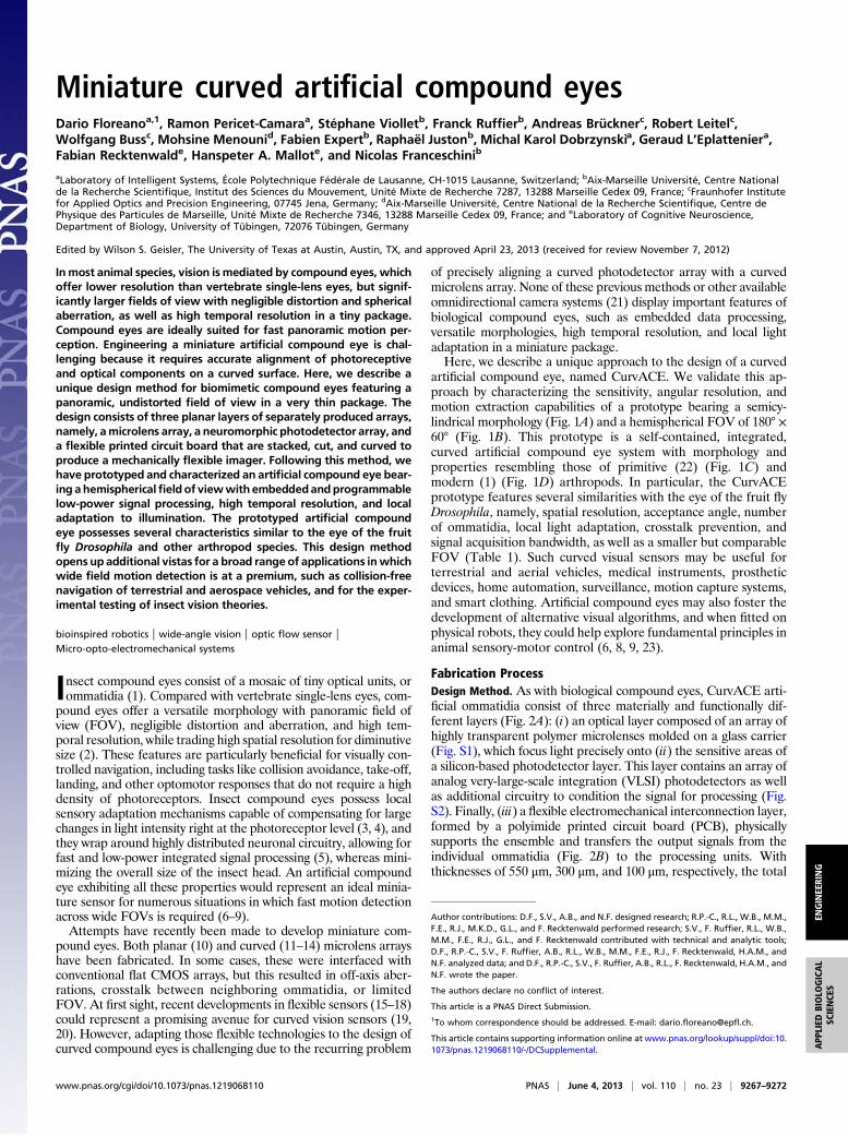
artificial compound eye, named CurvACE. We validate this ap-proach by characterizing the sensitivity, angular resolution, andmotion extraction capabilities of a prototype bearing a semicy-lindrical morphology (Fig. 1A) and a hemispherical FOV of 180° ×60° (Fig. 1B). This prototype is a self-contained, integrated,curved artificial compound eye system with morphology andproperties resembling those of primitive (22) (Fig. 1C) andmodern (1) (Fig. 1D) arthropods. In particular, the CurvACEprototype features several similarities with the eye of the fruit flyDrosophila, namely, spatial resolution, acceptance angle, numberof ommatidia, local light adaptation, crosstalk prevention, andsignal acquisition bandwidth, as well as a smaller but comparableFOV (Table 1). Such curved visual sensors may be useful forterrestrial and aerial vehicles, medical instruments, prostheticdevices, home automation, surveillance, motion capture systems,and smart clothing. Artificial compound eyes may also foster thedevelopment of alternative visual algorithms, and when fitted onphysical robots, they could help explore fundamental principles inanimal sensory-motor control (6, 8, 9, 23).
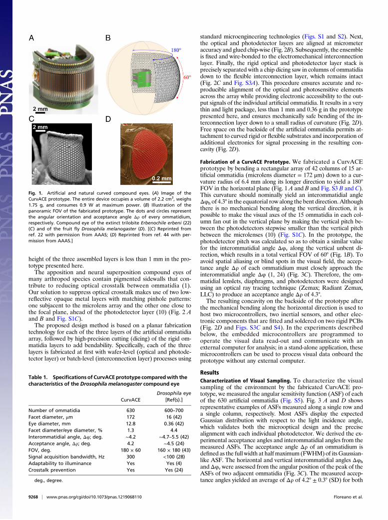
Fabrication ProcessDesign Method. As with biological compound eyes, CurvACE arti-ficial ommatidia consist of three materially and functionally dif-ferent layers (Fig. 2A): (i) an optical layer composed of an array ofhighly transparent polymer microlenses molded on a glass carrier(Fig. S1), which focus light precisely onto (ii) the sensitive areas ofa silicon-based photodetector layer. This layer contains an array ofanalog very-large-scale integration (VLSI) photodetectors as wellas additional circuitry to condition the signal for processing (Fig.S2). Finally, (iii) a flexible electromechanical interconnection layer,formed by a polyimide printed circuit board (PCB), physicallysupports the ensemble and transfers the output signals from theindividual ommatidia (Fig. 2B) to the processing units. Withthicknesses of 550 μm, 300 μm, and 100 μm, respectively, the total
Author contributions: D.F., S.V., A.B., and N.F. designed research; R.P.-C., R.L., W.B., M.M.,F.E., R.J., M.K.D., G.L., and F. Recktenwald performed research; S.V., F. Ruffier, R.L., W.B.,M.M., F.E., R.J., G.L., and F. Recktenwald contributed with technical and analytic tools;D.F., R.P.-C., S.V., F. Ruffier, A.B., R.L., W.B., M.M., F.E., R.J., F. Recktenwald, H.A.M., andN.F. analyzed data; and D.F., R.P.-C., S.V., F. Ruffier, A.B., R.L., F. Recktenwald, H.A.M., andN.F. wrote the paper.
The authors declare no conflict of interest.
This article is a PNAS Direct Submission.1To whom correspondence should be addressed. E-mail: [email protected].
This article contains supporting information online at www.pnas.org/lookup/suppl/doi:10.1073/pnas.1219068110/-/DCSupplemental.
www.pnas.org/cgi/doi/10.1073/pnas.1219068110 PNAS | June 4, 2013 | vol. 110 | no. 23 | 9267–9272
ENGINEE
RING
APP
LIED
BIOLO
GICAL
SCIENCE
S
height of the three assembled layers is less than 1 mm in the pro-totype presented here.The apposition and neural superposition compound eyes of
many arthropod species contain pigmented sidewalls that con-tribute to reducing optical crosstalk between ommatidia (1).Our solution to suppress optical crosstalk makes use of two low-reflective opaque metal layers with matching pinhole patterns:one subjacent to the microlens array and the other one close tothe focal plane, ahead of the photodetector layer (10) (Fig. 2 Aand B and Fig. S1C).The proposed design method is based on a planar fabrication
technology for each of the three layers of the artificial ommatidiaarray, followed by high-precision cutting (dicing) of the rigid om-matidia layers to add bendability. Specifically, each of the threelayers is fabricated at first with wafer-level (optical and photode-tector layer) or batch-level (interconnection layer) processes using
standard microengineering technologies (Figs. S1 and S2). Next,the optical and photodetector layers are aligned at micrometeraccuracy and glued chip-wise (Fig. 2B). Subsequently, the ensembleis fixed and wire-bonded to the electromechanical interconnectionlayer. Finally, the rigid optical and photodetector layer stack isprecisely separated with a chip dicing saw in columns of ommatidiadown to the flexible interconnection layer, which remains intact(Fig. 2C and Fig. S3A). This procedure ensures accurate and re-producible alignment of the optical and photosensitive elementsacross the array while providing electronic accessibility to the out-put signals of the individual artificial ommatidia. It results in a verythin and light package, less than 1 mm and 0.36 g in the prototypepresented here, and ensures mechanically safe bending of the in-terconnection layer down to a small radius of curvature (Fig. 2D).Free space on the backside of the artificial ommatidia permits at-tachment to curved rigid or flexible substrates and incorporation ofadditional electronics for signal processing in the resulting con-cavity (Fig. 2D).
Fabrication of a CurvACE Prototype. We fabricated a CurvACEprototype by bending a rectangular array of 42 columns of 15 ar-tificial ommatidia (microlens diameter = 172 μm) down to a cur-vature radius of 6.4 mm along its longer direction to yield a 180°FOV in the horizontal plane (Fig. 1 A and B and Fig. S3 B and C).This curvature should nominally yield an interommatidial angleΔφh of 4.3° in the equatorial row along the bent direction. Althoughthere is no mechanical bending along the vertical direction, it ispossible to make the visual axes of the 15 ommatidia in each col-umn fan out in the vertical plane by making the vertical pitch be-tween the photodetectors stepwise smaller than the vertical pitchbetween the microlenses (10) (Fig. S1C). In the prototype, thephotodetector pitch was calculated so as to obtain a similar valuefor the interommatidial angle Δφv along the vertical unbent di-rection, which results in a total vertical FOV of 60° (Fig. 1B). Toavoid spatial aliasing or blind spots in the visual field, the accep-tance angle Δρ of each ommatidium must closely approach theinterommatidial angle Δφ (1, 24) (Fig. 3C). Therefore, the om-matidial lenslets, diaphragms, and photodetectors were designedusing an optical ray tracing technique (Zemax; Radiant Zemax,LLC) to produce an acceptance angle Δρ of 4.3°.The resulting concavity on the backside of the prototype after
the mechanical bending along the horizontal direction is used tohost two microcontrollers, two inertial sensors, and other elec-tronic components that are fitted and soldered on two rigid PCBs(Fig. 2D and Figs. S3C and S4). In the experiments describedbelow, the embedded microcontrollers are programmed tooperate the visual data read-out and communicate with anexternal computer for analysis; in a stand-alone application, thesemicrocontrollers can be used to process visual data onboard theprototype without any external computer.
ResultsCharacterization of Visual Sampling. To characterize the visualsampling of the environment by the fabricated CurvACE pro-totype, we measured the angular sensitivity function (ASF) of eachof the 630 artificial ommatidia (Fig. S5). Fig. 3 A and D showsrepresentative examples of ASFs measured along a single row anda single column, respectively. Most ASFs display the expectedGaussian distribution with respect to the light incidence angle,which validates both the microoptical design and the precisealignment with each individual photodetector. We derived the ex-perimental acceptance angles and interommatidial angles from themeasured ASFs. The acceptance angle Δρ of an ommatidium isdefined as the full width at halfmaximum (FWHM)of itsGaussian-like ASF. The horizontal and vertical interommatidial angles ΔφhandΔφv were assessed from the angular position of the peak of theASFs of two adjacent ommatidia (Fig. 3C). The measured accep-tance angles yielded an average of Δρ of 4.2° ± 0.3° (SD) for both
Fig. 1. Artificial and natural curved compound eyes. (A) Image of theCurvACE prototype. The entire device occupies a volume of 2.2 cm3, weighs1.75 g, and consumes 0.9 W at maximum power. (B) Illustration of thepanoramic FOV of the fabricated prototype. The dots and circles representthe angular orientation and acceptance angle Δρ of every ommatidium,respectively. Compound eye of the extinct trilobite Erbenochile erbeni (22)(C) and of the fruit fly Drosophila melanogaster (D). [(C) Reprinted fromref. 22 with permission from AAAS; (D) Reprinted from ref. 44 with per-mission from AAAS.]
Table 1. Specifications of CurvACEprototype comparedwith thecharacteristics of the Drosophila melanogaster compound eye
CurvACEDrosophila eye
[Ref(s).]
Number of ommatidia 630 600–700Facet diameter, μm 172 16 (42)Eye diameter, mm 12.8 0.36 (42)Facet diameter/eye diameter, % 1.3 4.4Interommatidial angle, Δφ; deg. ∼4.2 ∼4.7–5.5 (42)Acceptance angle, Δρ; deg. 4.2 ∼4.5 (24)FOV, deg. 180 × 60 160 × 180 (43)Signal acquisition bandwidth, Hz 300 <100 (28)Adaptability to illuminance Yes Yes (4)Crosstalk prevention Yes Yes (24)
deg., degree.
9268 | www.pnas.org/cgi/doi/10.1073/pnas.1219068110 Floreano et al.
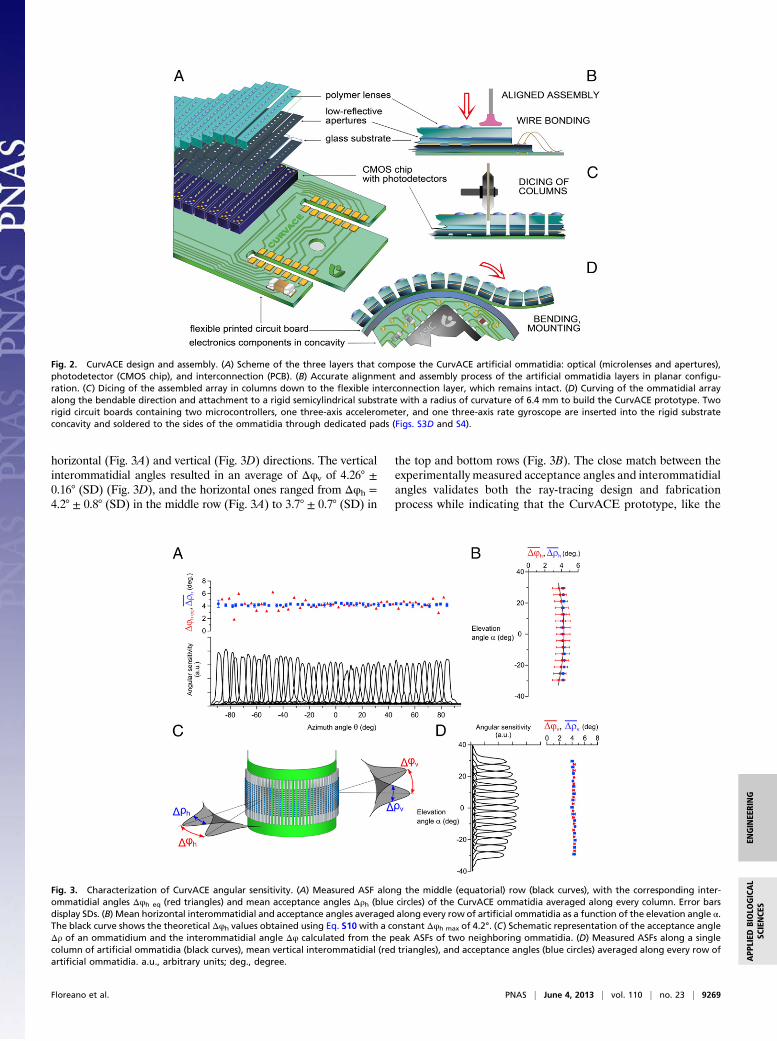
horizontal (Fig. 3A) and vertical (Fig. 3D) directions. The verticalinterommatidial angles resulted in an average of Δφv of 4.26° ±0.16° (SD) (Fig. 3D), and the horizontal ones ranged from Δφh =4.2° ± 0.8° (SD) in the middle row (Fig. 3A) to 3.7° ± 0.7° (SD) in
the top and bottom rows (Fig. 3B). The close match between theexperimentally measured acceptance angles and interommatidialangles validates both the ray-tracing design and fabricationprocess while indicating that the CurvACE prototype, like the
Fig. 2. CurvACE design and assembly. (A) Scheme of the three layers that compose the CurvACE artificial ommatidia: optical (microlenses and apertures),photodetector (CMOS chip), and interconnection (PCB). (B) Accurate alignment and assembly process of the artificial ommatidia layers in planar configu-ration. (C) Dicing of the assembled array in columns down to the flexible interconnection layer, which remains intact. (D) Curving of the ommatidial arrayalong the bendable direction and attachment to a rigid semicylindrical substrate with a radius of curvature of 6.4 mm to build the CurvACE prototype. Tworigid circuit boards containing two microcontrollers, one three-axis accelerometer, and one three-axis rate gyroscope are inserted into the rigid substrateconcavity and soldered to the sides of the ommatidia through dedicated pads (Figs. S3D and S4).
Fig. 3. Characterization of CurvACE angular sensitivity. (A) Measured ASF along the middle (equatorial) row (black curves), with the corresponding inter-ommatidial angles Δφh eq (red triangles) and mean acceptance angles Δρh (blue circles) of the CurvACE ommatidia averaged along every column. Error barsdisplay SDs. (B) Mean horizontal interommatidial and acceptance angles averaged along every row of artificial ommatidia as a function of the elevation angle α.The black curve shows the theoretical Δφh values obtained using Eq. S10with a constant Δφh max of 4.2°. (C) Schematic representation of the acceptance angleΔρ of an ommatidium and the interommatidial angle Δφ calculated from the peak ASFs of two neighboring ommatidia. (D) Measured ASFs along a singlecolumn of artificial ommatidia (black curves), mean vertical interommatidial (red triangles), and acceptance angles (blue circles) averaged along every row ofartificial ommatidia. a.u., arbitrary units; deg., degree.
Floreano et al. PNAS | June 4, 2013 | vol. 110 | no. 23 | 9269
ENGINEE
RING
APP
LIED
BIOLO
GICAL
SCIENCE
S

fruit fly compound eye (24), performs an adequate sampling of itsentire FOV (Fig. 1B). The observed spread in the values of thehorizontal interommatidial angles Δφh (Fig. 3 A and B) is prob-ably due to the manual process used to mechanically fix theflexible PCB supporting the artificial ommatidia array onto therigid curved substrate.
Characterization of Ommatidium Light Adaptation. In the naturalworld, visual sensors must cope with a wide dynamic range of ir-radiance, which can span on the order of 8 decades over the courseof a day. Light variations within a scene are particularly challengingbecause they can make part of the visual field nonresponsive due tophotoreceptor saturation. Animal retinae partly solve this crucialproblem bymeans of a local light adaptationmechanism integratedwithin each photoreceptor (3, 4, 25, 26). Similarly, we have equip-ped each prototype ommatidium with a neuromorphic adaptationcircuit (Fig. S2D) that operates independent of its 629 neigh-bors. The neuromorphic circuit originally proposed by Delbrückand Mead (27) was modified here by cascading a first-order, low-pass filter (Fig. S2D). This modification prevents temporal alias-ing and keeps the photodetector bandwidth of 300 Hz practicallyconstant across the entire studied range of ambient lightingconditions. The circuit design was further optimized (SI Text,Photodetector Layer) to minimize the transient gain dispersion ofeach autoadaptive circuit. Fig. 4 shows the mean steady state andtransient responses of 11 artificial ommatidia (photodetectorswith optics) in one column to light step increments and decre-ments presented at four different steady light levels (Fig. S6). Ateach of these four levels (red circles in Fig. 4), the output responseof the individual ommatidia to light steps yields an S-shaped op-erating curve in a semilog plot. Adaptation to a novel steady ir-radiance level essentially produces a horizontal shift of the curvewithout markedly changing its slope, which represents a dynamicsensitivity of about 1,300 mV per decade in the linear part. Thesteady operating curve (shown in red in Fig. 4) is also a loga-rithmic function of the adapting light, but with a slope (steadysensitivity) about 12-fold smaller. Thanks to the optimized designof the adaptive photodetector layout, the averaged dispersion ofthe sensitivity over the four operating curves is as small as 11 mV,that is, only about 2% of the total 600-mV dynamic range.The four operating curves demonstrate not only the high sen-
sitivity of the prototype ommatidia but their relative invariance insensitivity to the ambient light. These V(log I) curves shifting withthe operating points are reminiscent of those obtained in analogous
experiments carried out on single vertebrate (25) and invertebrate(26) photoreceptors. This local adaptation is essential for efficientsampling of natural environments because it prevents saturation ofthe photoreceptors by bright spots in the visual scene while allowingthem to adapt quickly to untoward illumination changes, such astransitions from a shaded area to a sunny place.
Characterization of Motion Extraction. In addition to an extensiveFOV (Fig. 3) and local adaptation to illuminance (Fig. 4), theCurvACE prototype ommatidia yield a signal acquisition band-width of 300 Hz, which is threefold higher than that measured inthe ommatidia of fast-flying insects (28). A high bandwidth con-tributes to the reduction of motion aliasing during fast locomotion.Furthermore, the implemented read-out protocol (Fig. S7) allowsa maximum frame rate of 1.5 kfps, which permits frame averagingto improve the signal-to-noise ratio. We experimentally testedCurvACE motion detection capabilities by computing optic flowvectors from visual signals resulting from different types of motionin the presence of random black and white patterns on a wall (Fig.S8). In this first experiment, we used a modified version of theLucas–Kanademethod (29, 30) (SI Text, Optic Flow Characterizationand Eqs. S1–S9), which is a particularly efficient image-based pro-cessing algorithm used to calculate optic flow vectors in twodimensions. The optic flow vectors measured during roll rotation(Fig. 5A) and linear translation toward a textured wall 0.3 s beforecollision (Fig. 5B) show coherent patterns of visual rotation andexpansion, respectively. The center of rotation and focus of ex-pansion can be clearly identified (red dots in Fig. 5), allowing forestimation of the axis of rotation and of the direction of translation,respectively. The sensor egomotion can be estimated from theseflow fields, for instance, by implementing matched filters (31)analogous to the directionally selective, motion-sensitive neuronsfound in some insect visual systems (5). Furthermore, the embed-ded inertial sensors can be used for cancelling the rotational com-ponent of the measured optic flow, assessing only the translationalcomponent. Because this component is related to distance fromobjects, the optic flowdata provided by a CurvACEprototype couldassist mobile platforms to perform collision-free navigation (9).We also characterized motion detection quantitatively at dif-
ferent ambient light levels with a bioinspired local visual processing
Fig. 4. CurvACE autoadaptation to ambient light at the single ommatidiumlevel. Steady-state (red dots) and transient (green dots) responses of theadaptive analog VLSI photodetectors [design based on a circuit proposed byDelbrück and Mead (27)]. Each of the four dynamic operating curves (ingreen) shows the V(log I) response, averaged over 11 ommatidia (photo-detectors with optics) of one column, to step increments and decrements ofirradiance (Fig. S6) about four steady levels (red circles).
Fig. 5. Optic flow fields from the CurvACE prototype. Cylindrical equidis-tant projections of the optic flow field calculated with a modified version ofthe Lucas–Kanade method (29, 30) from the visual signals obtained by theCurvACE prototype subjected to roll motion (Fig. S8B) at 32° per second andat a distance of about 1 m to a wall displaying random black and whitepatterns (A) or to linear translation (Fig. S8C) at 3 cm/s toward the patternedwall at a distance of 1 cm (B). The red spot displays the center of rotation (A)or the focus of expansion (B).
9270 | www.pnas.org/cgi/doi/10.1073/pnas.1219068110 Floreano et al.

algorithm based on the “time-of-travel” scheme (32) (Fig. S9). Fig.6 shows the angular speed ωmedian obtained by measuring the ro-tational optic flow as a function of the yaw rotational speed ofCurvACE surrounded by a natural pattern. The experimental datashow a good match between the rotational speed perceived byCurvACE and the true rotational speed. The error in the re-gression coefficient (linearity error) ranges from 5 to 10% (Fig. 6)
at the three illumination levels, indicating that the CurvACE sensortakes full advantage of its autoadaptive analogVLSI photodetectorsto make motion detection largely invariant to different illuminationconditions. With the time-of-travel scheme, any pair of neighboringommatidia driving a “local motion sensor” is able to measure an-gular velocities ranging from 50° to 358° per second for the inter-ommatidial angle of 4.2° with sufficient accuracy. Measurementlimitation at lower speeds is due to the signal attenuation broughtabout by the spatiotemporal processing present in each artificialommatidium (Fig. S9A).
DiscussionThe prototype presented here represents one of many possiblemanifestations of the CurvACE design principle. It yieldsa compact, lightweight, energy-efficient, miniature vision sensorthat suits a broad range of applications requiring fast motiondetection across a panoramic FOV. The applied optical andelectronic parameters enable this prototype to measure opticflow patterns caused by sensor egomotion within a contrastedenvironment. A prototype with these characteristics could beused for autonomous terrestrial navigation, in analogy withsome crab species (33) that use quasicylindrical compound eyes tonavigate in flat environments. Furthermore, the hemispherical FOVof the prototype obtained by horizontal bending and by the longermicrolens vertical pitch distance resembles the FOV of flying insects(1). Thus, such a prototype could also be used inMicro Air Vehicles(MAV) to support a large number of navigation tasks, such asegomotion estimation (34), collision avoidance (6, 7), and flightcontrol (8, 9, 35), at low and high speeds, even in complex indoor andoutdoor environments.The CurvACE design principle also allows for flexible cus-
tomization of artificial ommatidia in terms of their number, size,focal length, and interommatidial and acceptance angles, ac-cording to the requirements of the intended use. The artificialommatidia could be further tailored by taking inspiration from theextraordinary eye regionalization found in insects and crusta-ceans, where specific parts of the compound eye serve specificfunctions. For example, higher acuity (36) may be obtained byincreasing ommatidial resolution in defined areas, which could beachieved by decreasing both the acceptance angle and the inter-ommatidial angle through redesigned microlenses and a reducedphotodetector size with a consequent loss of signal-to-noise ratio.Design variations in the ommatidial optics or photodetectorcharacteristics could yield regions of higher light capture (37) ordifferent spectral (38) or polarization sensitivity (39).The size of the CurvACE prototype described here is com-
parable to that of some trilobite eyes (22) (Fig. 1C) and somecrab eyes (33), but reaching the diminutive size of insect eyes ischallenging because it implies various tradeoffs. Increasing thesurface density of artificial ommatidia requires decreasingphotosensor size, chip circuitry, and microlens diameter at thecost of lower sensitivity and signal-to-noise ratio. Consideringstate-of-the-art technologies, we have estimated that the Cur-vACE prototype could be further reduced by a factor of 2.Further increments of surface density via hexagonal arrange-ment of ommatidia, similar to that found in many insect eyes,may be possible but would require different cutting methods. Inthe future, the development of vertical integration of 3D elec-tronic circuits could further reduce the footprint size at the costof chip thickness.The CurvACE design opens up new avenues for vision sensors
with alternative morphologies and FOVs of up to 360° in small,compact packages. In particular, the realization of a fully cylin-drical CurvACE with a 360° FOV in the horizontal plane is rel-atively straightforward, either by attaching two semicylindricalprototypes (Fig. S4D) or by fabricating a wider array with a largernumber of ommatidia. A CurvACE prototype with a truly om-nidirectional FOV, reminiscent of the eye morphology of most
Fig. 6. Characterization of CurvACE motion detection capabilities. (A–C )Angular speed characteristics of CurvACE calculated with a method basedon the time-of-travel scheme (32) (Fig. S9) assessed by applying steps ofyaw rotational speed Ωyaw to the sensor at 10° per second, lasting 10 seach, with the prototype placed at the center of a 105-cm diameter arenalined with prints of a natural image. The dashed line displays the theo-retical trend.
Floreano et al. PNAS | June 4, 2013 | vol. 110 | no. 23 | 9271
ENGINEE
RING
APP
LIED
BIOLO
GICAL
SCIENCE
S

flying insects, would be especially interesting for egomotion es-timation and better navigational support in three dimensions ina minimal package, providing an advantageous alternative tocurrent cumbersome arrangements based on catadioptric orfish-eye lenses (9). A spherical CurvACE could be realized byfabricating and individually bending several ommatidial arrayswith one ommatidium per column along the meridians ofa sphere to measure optic flow omnidirectionally.The CurvACE design is expected to foster further research and
applications on fully flexible vision sensors (40, 41) that can adaptto rigid or unsteady surfaces of arbitrary shapes. Such devicescould function as thin wearable sensors on smart clothing, assensors for intelligent homes, or integrated in the artificial skin ofsoft robots. Toward these applications, future work could devisemethods for cost-effective mass production of artificial omma-tidia, which would also allow more complex dicing to achievealternative bending patterns. Such production methods may in-
clude the realization of all processes of ommatidia alignment andassembly at the wafer level with the help of robotic platforms forautomatized pick-and-place, bonding, and dicing.
ACKNOWLEDGMENTS. We thank Jean-Christophe Zufferey and JacquesDuparré for conceptual suggestions; Stéphanie Godiot, Patrick Breugnon,Alain Calzas, Rémy Potheau, and Marc Boyron for their help in VLSI circuitdesign and tests; Felix Kraze for assisting in prototype assembly; Julien Diperifor test bench realization; David O’Carroll and Russell Brinkworth for thenatural photograph used in optic flow characterization setup; Antoine Bey-eler for the CurvACE prototype photograph; and Claudio Bruschini for projectmanagement. We also thank the anonymous reviewers, whose commentshave contributed largely to improve the manuscript. The CURVACE projectacknowledges the financial support of the Future and Emerging Technologies(FET) programwithin the Seventh Framework Programme for Research of theEuropean Commission, under FET-Open Grant 237940. This work also re-ceived financial support from the Swiss National Centre of Competence inResearch Robotics of the Swiss National Science Foundation, the French Na-tional Center for Scientific Research and Aix-Marseille University, the FrenchNational Research Agency, and the German Federal Ministry of Educationand Research.
1. Land MF, Nilsson D-E (2002) Animal Eyes (Oxford Univ Press, Oxford).2. Kirschfeld K (1976) The resolution of lens and compound eyes. Neural Principles in
Vision, eds Zettler F, Weiler R (Springer, Berlin), pp 354–370.3. Laughlin SB (1989) The role of sensory adaptation in the retina. J Exp Biol 146(1):
39–62.4. Gu Y, Oberwinkler J, Postma M, Hardie RC (2005) Mechanisms of light adaptation in
Drosophila photoreceptors. Curr Biol 15(13):1228–1234.5. Krapp HG, Hengstenberg R (1996) Estimation of self-motion by optic flow processing
in single visual interneurons. Nature 384(6608):463–466.6. Franceschini N, Pichon JM, Blanes C (1992) From insect vision to robot vision. Philos
Trans R Soc Lond B Biol Sci 337(1281):283–294.7. Blanchard M, Rind FC, Verschure PFMJ (2000) Collision avoidance using a model of the
locust LGMD neuron. Robot Auton Syst 30(1–2):17–38.8. Franceschini N, Ruffier F, Serres J (2007) A bio-inspired flying robot sheds light on
insect piloting abilities. Curr Biol 17(4):329–335.9. Floreano D, Zufferey J-C, Srinivasan MV, Ellington C (2009) Flying Insects and Robots
(Springer, Berlin).10. Duparré J, Dannberg P, Schreiber P, Bräuer A, Tünnermann A (2005) Thin compound-
eye camera. Appl Opt 44(15):2949–2956.11. Jeong K-H, Kim J, Lee LP (2006) Biologically inspired artificial compound eyes. Science
312(5773):557–561.12. Radtke D, Duparré J, Zeitner UD, Tünnermann A (2007) Laser lithographic fabrication
and characterization of a spherical artificial compound eye. Opt Express 15(6):3067–3077.
13. Pulsifer DP, Lakhtakia A, Martín-Palma RJ, Pantano CG (2010) Mass fabricationtechnique for polymeric replicas of arrays of insect corneas. Bioinspir Biomim 5(3):036001.
14. Qu P, et al. (2012) A simple route to fabricate artificial compound eye structures. OptExpress 20(5):5775–5782.
15. Khang D-Y, Jiang H, Huang Y, Rogers JA (2006) A stretchable form of single-crystalsilicon for high-performance electronics on rubber substrates. Science 311(5758):208–212.
16. Dinyari R, Rim S-B, Huang K, Catrysse PB, Peumans P (2008) Curving monolithic siliconfor nonplanar focal plane array applications. Appl Phys Lett 92(9):091114–091113.
17. Xu X, Davanco M, Qi X, Forrest SR (2008) Direct transfer patterning on three di-mensionally deformed surfaces at micrometer resolutions and its application tohemispherical focal plane detector arrays. Org Electron 9(6):1122–1127.
18. Lee J, Kim J (2011) Fabrication of strongly anchored, high aspect ratio elastomericmicrowires for mechanical and optical applications. J Micromech Microeng 21(8):085016–085024.
19. Jung I, et al. (2011) Dynamically tunable hemispherical electronic eye camera systemwith adjustable zoom capability. Proc Natl Acad Sci USA 108(5):1788–1793.
20. Dumas D, et al. (2012) Infrared camera based on a curved retina. Opt Lett 37(4):653–655.
21. Ferrat P, et al. (2008) Ultra-miniature omni-directional camera for an autonomous flyingmicro-robot. Conference on Optical and Digital Image Processing, eds Schelkens P,Ebrahimi T, Cristobal G, Truchetet F (Proc SPIE, Bellingham, WA), Vol 7000, pp 70000M-1–70000M-10.
22. Fortey R, Chatterton B (2003) A Devonian trilobite with an eyeshade. Science301(5640):1689.
23. Webb B (2002) Robots in invertebrate neuroscience. Nature 417(6886):359–363.24. Götz KG (1965) Die optischen Übertragungseigenschaften der Komplexaugen von
Drosophila. Biol Cybern 2(5):215–221, German.25. Normann RA, Perlman I (1979) The effects of background illumination on the pho-
toresponses of red and green cones. J Physiol 286(1):491–507.26. Mati�c T, Laughlin SB (1981) Changes in the intensity-response function of an insect’s
photoreceptors due to light adaptation. J Comp Physiol 145(2):169–177.27. Delbrück T, Mead CA (1994) Adaptive photoreceptor with wide dynamic range. IEEE
International Symposium on Circuits and Systems (IEEE, New York, NY), pp 339–342.28. Laughlin SB, Weckström M (1993) Fast and slow photoreceptors—A comparative
study of the functional diversity of coding and conductances in the Diptera. J CompPhysiol A Neuroethol Sens Neural Behav Physiol 172(5):593–609.
29. Lucas BD, Kanade T (1981) An iterative image registration technique with an appli-cation to stereo vision. Proceedings of the Seventh International Joint Conference onArtificial Intelligence, ed Hayes PJ (William Kaufmann, Los Altos, CA), pp 674–679.
30. Fleet DJ, Langley K (1995) Recursive filters for optical flow. IEEE Trans Pattern AnalMach Intell 17(1):61–67.
31. Franz MO, Krapp HG (2000) Wide-field, motion-sensitive neurons and matched filtersfor optic flow fields. Biol Cybern 83(3):185–197.
32. Pichon J-M, Blanes C, Franceschini N (1989) Visual guidance of a mobile robotequipped with a network of self-motion sensors. Mobile Robots IV, eds Chun WH,Wolfe WJ (Proc SPIE, Vol 1195), pp 44–55.
33. Zeil J, Al-Mutairi M (1996) The variation of resolution and of ommatidial dimensions inthe compound eyes of the fiddler crab Uca lactea annulipes (Ocypodidae, Brachyura,Decapoda). J Exp Biol 199(Pt 7):1569–1577.
34. Plett J, Bahl A, Buss M, Kühnlenz K, Borst A (2012) Bio-inspired visual ego-rotationsensor for MAVs. Biol Cybern 106(1):51–63.
35. Kerhuel L, Viollet S, Franceschini N (2010) Steering by gazing: An efficient biomimeticcontrol strategy for visually guided micro aerial vehicles. IEEE Trans Robot 26(2):307–319.
36. Horridge GA (1978) The separation of visual axes in apposition compound eyes. PhilosTrans R Soc Lond B Biol Sci 285(1003):1–59.
37. Hateren JH, Hardie RC, Rudolph A, Laughlin SB, Stavenga DG (1989) The bright zone,a specialized dorsal eye region in the male blowfly Chrysomyia megacephala. J CompPhysiol A Neuroethol Sens Neural Behav Physiol 164(3):297–308.
38. Franceschini N, Hardie R, Ribi W, Kirschfeld K (1981) Sexual dimorphism in a photo-receptor. Nature 291(5812):241–244.
39. Labhart T (1980) Specialized photoreceptors at the dorsal rim of the honeybee’scompound eye: Polarizational and angular sensitivity. J Comp Physiol 141(1):19–30.
40. Daneshpanah M, Javidi B (2011) Three-dimensional imaging with detector arrays onarbitrarily shaped surfaces. Opt Lett 36(5):600–602.
41. Dobrzynski MK, Pericet-Camara R, Floreano D (2012) Vision Tape—A flexible com-pound vision sensor for motion detection and proximity estimation. IEEE Sens J 12(5):1131–1139.
42. Franceschini N, Kirschfeld K (1971) Les phénomènes de pseudopupille dans l’œilcomposé de Drosophila. Biol Cybern 9(5):159–182. French.
43. Heisenberg M, Wolf R (1984) Vision in Drosophila: Genetics of Microbehavior(Springer, Berlin).
44. Lee JH, et al. (2010) Sestrin as a feedback inhibitor of TOR that prevents age-relatedpathologies. Science 327(5970):1223–1228.
9272 | www.pnas.org/cgi/doi/10.1073/pnas.1219068110 Floreano et al.
Supporting InformationFloreano et al. 10.1073/pnas.1219068110SI Text
Prototype Parts and AssemblyOptics Layer. The generation of the compound eye multiapertureoptics involves the formation of a chirped microlens array (lensletdiameter of 172 μm) and two chirped aperture arrays (1) (Fig.S1C). This implies toroidal-shaped lenslets and pitch differencesbetween the layers and the photodetectors on the sensor wafer aswell (microlens pitch of 290 μm > photoreceptor pitch of 260μm). The microlenses are formed by reflow of photoresist andsubsequent UV molding of a highly transparent polymer (Or-mocer, Ormocomp; Micro Resist Technology) (Fig. S1 A and B).Low-reflective chromium films are used to create two aperturelayers, which are deposited by sputtering and patterned by UVphotolithography and subsequent metal etching. The opticsf-number is 2.4. The resist patterning and UV molding have beencarried out using a mask aligner device (Süss Microtec AG).
Photodetector Layer. This layer consists of an optoelectronicchip fabricated in silicon at wafer level using CMOS technology(0.35-μm technology with Opto option; X-FAB SemiconductorFoundries). Every chip has a size of 20× 6.765mm2 and consists of42 columns, each bearing 15 VLSI autoadaptive photodetectors,a bias circuit, a 10-bit analog-to-digital converter (ADC), anda logic circuit that implements a serial interface for the read-outprotocol (Fig. S2).Every autoadaptive photoreceptor consists of a logarithmic circuit
associated with a high-gain negative feedback loop as proposed byDelbrück and Mead (2) (Fig. S2D). A MOSFET transistor (MFB inFig. S2D) operates in the subthreshold region where the current-to-voltage characteristic follows a logarithmic law. Thus, the photore-ceptor operates over several decades of ambient light level, gener-ating the low-gain direct current operating curve shown as a reddotted line in Fig. 4. In addition, transient signals are amplified witha variable gain depending on the equivalent resistance of theadaptive element: The lower the output signal level (Vout), thehigher is the gain. The autoadaptive feature is used to compensatefor ambient light changes, that is, to keep the photodetectors re-sponding to contrasting features even in intense ambient lighting.The overall bandwidth of the photoreceptor depends on the current(Iph in Fig. S2D) flowing into the photodiode and on the timeconstants of the amplifier stage. For high ambient lighting levels, thebandwidth can be as large as 500 kHz. To prevent aliasing during thedigitization process, we deliberately enhanced the circuit by limitingthe bandwidth of each photodetector to about 300Hz by cascading itwith an antialiasing filter, consisting of a first-order low-pass filterbased on a transconductance amplifier. To limit the dispersion dueto the CMOS technology, we finely adjusted the ratio between thetwo capacitors (C1 and C2 in Fig. S2D) to minimize the transientgain dispersion of the photodetectors.Every photoreceptor column bears a multiplexer and a 10-bit
ADC with a conversion time of 15 μs. The analog signal of the 15photodetectors is sequentially converted by the multiplexedADC and sent to the microcontroller unit through a synchronousserial interface.
Printed Circuit Boards. Interconnection layer. Printed circuit boards(PCBs) are used to connect the different electronic components ofthe curved artificial compound eye (CurvACE) electrically whileensuring their mechanical support. In the case of the ommatidiainterconnection layer, a polyimide (Kapton) one-layer PCB witha thickness of 100 μm is used. The low thickness and the absence of
vias allow curving the ommatidia down to the required 6.4-mmradius of curvature (ROC). Themiddle part of the PCB is left emptyof tracks because that is the positionwhere the photoreceptor layer isplaced. Tracks for analog and digital power and ground, as well as forclock, sync, and digital data read-out, are routed to operate all col-umns (read-out protocol is shown in Fig. S7).Rigid internal PCBs. The CurvACE prototype bears two rigid PCBsthat, in addition to the interconnection layer of the artificial om-matidia, provide mechanical and electrical support to the internalelectronic components. They are made of FR-4 (fiberglass withepoxy resin), have a nominal thickness of 0.5mm, and are placed inthe concavity of the sensor and perpendicular to theflex PCB.Theyare electrically connected to the artificial ommatidia by connectingpads placed along their edges (Fig. S4). Both rigid PCBs are alsointerconnected electrically via those connecting pads throughtracks designed along the outer side of the interconnection layer.The used electronic components of the CurvACE prototype
are soldered onto these rigid PCBs. More precisely, the micro-controllers of model dsPIC33FJ128GP802 (Microchip Technol-ogy) are soldered on top of eachPCB. Two inertial sensors, a three-axis accelerometer MMA7455L (Freescale Semiconductor), anda three-axis rate gyroscope ITG-3200 (InvenSense) are placed atthe bottom side of the top PCB. Two low-drop-out voltage regu-lators EXAR-SP6201EM5-L-3-3 (EXAR) and the external con-nector lie at the bottom side of the bottom PCB (Fig. S3).
Ommatidia Assembly Process. Bonding. The alignment and gluebonding assembly of the three artificial ommatidia layers is done viaa Fineplacer device (Finetech GmbH&Co. KG, Berlin, Germany)that yields a precision down to 1 μm. The glue bonding between theoptics and photoreceptor layers is realized with a high-transparentUV-curing adhesive EPO-TEK OG 146 (Epoxy Technology Inc.,Billerica, MA). To improve the bonding strength, a silane-basedadhesion promoter has been applied to both surfaces before gluing.The glue bonding between the photoreceptor and the intercon-nection layer is realized applying a thermally curing adhesive EPO-TEK353ND.The photoreceptor layer is electrically connected withthe interconnection layer by wedge bonding with aluminumwires of30 μm. The wires are protected with a transparent glob-topmaterial(Fig. S3A).Intercolumn dicing. The dicing of the bonded optics and photore-ceptor layer in 42 columns is realized by an automatic dicing setup(DISCO Corp.). A special 100-μm-thick synthetic-resin com-pound dicing blade for rigorous and brittle materials was appliedfor trenching and dicing the columns.
Prototype Assembly. A rigid and hard internal scaffold fabricatedin polyoxomethylene by five-axis milling with CNC technology isused as mechanical support of the CurvACE PCBs.For the prototype assembly, the artificial ommatidia supported
by the flex PCB are bent and placed onto the curved outer side ofthe scaffold, which bears the required ROC of 6.4 mm, and aresubsequently fixed. The rigid PCBs, bearing the microcontrollersand inertial sensors soldered (Fig. S4), are introduced in thecylinder concavity along two mechanical guides in the scaffold.Subsequently, the rigid PCB side pads are soldered to the om-matidia flex PCB end pads.
Read-Out Interface. The CurvACE prototype uses a serial directconnection protocol as a read-out interface to communicate withthe controller units (Fig. S7). It consists of a unique clock signalsent to each ommatidial column, two sync signals used to start
Floreano et al. www.pnas.org/cgi/content/short/1219068110 1 of 7
the ADC conversion of the associated columns, and a digitalsignal per column used for the serial transfer of each omma-tidium output signal. The clock and sync signals are emitted bythe embedded microcontrollers, which also collect the outputdata for processing. With a clock frequency of 1 MHz and anADC conversion time of 16 μs for each ommatidium, the max-imum frame rate that can be achieved is 1.95 kfps. After pro-tocol implementation, the measured frame rate for thisprototype is 1.5 kfps.
Characterization SetupsOmmatidia Sensitivity Characterization. Optical characterization. Theoptical characterization of the CurvACE prototype implies thecharacterization of the optical angular sensitivity of each pixel inboth directions: along rows and along columns (Fig. 3 A and D).For this, a LabVIEW software suite [including Real-Time andField-Programmable Gate Array (FPGA) LabVIEW software;National Instruments] was used to acquire data from the CurvACEprototype through a 16-bit serial peripheral interface (SPI) bus.To characterize the angular sensitivity of each pixel, the CurvACEprototype is set on a test bench (Fig. S5) composed of two rotarystages to select a specific row or column, two linear stages (2 dfand 3 df) to set the center of rotation accurately at the center ofthe CurvACE prototype, a stepper motor to rotate the cylindricalCurvACE by steps of 0.1° along a specific row or column, and aresolver to measure accurately the actual prototype rotation im-posed by the stepper motor. The angular position is then calcu-lated by the FPGA software at 4 kHz. A goniometer supportingthe overall mechanical assembly performs the line or column se-lection with a resolution of 1 arc minute (0.017°). To change theconfiguration of the test bench between row and column charac-terization, the setup is readapted. In particular, adjustments of the3-df linear stages are made with metrology instruments.A 20-Hz flickering point light source based on a white light
emitting diode (LED), followed by a diaphragm with a diameterof 1 mm, is placed at a distance of 2.8 m from the photodetectorsto illuminate them from a predetermined direction. Steppermotor control, angular measurements, and signal acquisitionfrom the CurvACE are achieved through a LabVIEW NIEmbedded Software Evaluation Toolkit (National Instru-ments). The obtained signal, which represents the ommatidiaASF shown in Fig. 3 A and D, has been smoothed by means ofa low-pass filter.Light sensitivity characterization.Wedeveloped a programmable lightbox able to create an illuminance varying between 1 and 10,000 luxat a distance of 3 cm, where the CurvACE prototype was placed.The light intensity could be digitally adjusted through an RS232bus.This highly controlled light environment allows the responseofanommatidium(photodetectorwithoptics) tobemeasuredbothasa functionof the steady illuminanceandasa functionof incrementalanddecremental light steps presentedabout the steady illuminance(Fig. S6).Very low illuminancevalueswereobtainedbymeansofanadditional neutral density glass filter (thickness of 2 mm, opticaldensity OD = 2, HG3; Schott) placed between the LED(TLWR7600; Vishay) and the CurvACE prototype. An additionaldigital input signal sent by the FPGA software was used to syn-chronize the changes in light intensity with the CurvACE read-out. The irradiance of the light source was measured by means ofa radiometer (ILT1700, International Light Technologies Inc.,Peabody, MA), whose probe was placed at a distance of 28 mmfrom the light source.
Optic Flow Characterization. Optic flow was extracted from theCurvACE sensor by subjecting it to different kinds of motion whileacquiring the photoreceptor signals on a personal computer. Forthis, thesensorwasmountedat the tipofamechanicalarm,allowingfor its free positioning and orientation (Fig. S8A). Two differentsetups are used. To impose a rotational motion, the prototype
sensor is mounted on a rotary table surrounded by patternedcardboard. The rotary disk is driven by a stepper motor at a fixedrotational speed between 4.5° and 40° per second (Fig. S8B). Forimposing a translational motion, the sensor is mounted on a car-riage driven by a stepper motor via a tension chain. Fig. S8C showsthe carriage on rails passing by a textured wall. For the flow patternshown in Fig. 5B, the sensor was frontally approaching a wallshowing the same texture.For the experiments in translation, and roll rotation (Fig. 5), we
used a noniterative, gradient-based, multiframe optic flow ex-traction method derived from the one developed by Lucas andKanade (3) and inspired by the work of Fleet and Langley (4).Before computation, a bias in the response of the CurvACEommatidia is removed to improve gradient calculation. The al-gorithm is derived from the optic flow constraint
Ixu+ Iyv+ It = 0; [S1]
which can be derived from the image brightness constancy as-sumption using first-order Taylor expansion. Here, ðu; vÞ is theflow vector and I is the image function, with subscripts denotingpartial derivatives. A spatiotemporal weighted least-squares so-lution at time t over the image patch P is given by
minX∞
i= 0
X
x;y∈PwðiÞ�Ixðx; y; t− iÞu+ Iyðx; y; t− iÞv+ It
�x; y; t− i
��2 = 0;
[S2]
with wðiÞ= ð1− αÞαi defining the exponential weighting functionin the time domain. This can be solved by
ðu; vÞ=G−1A; [S3]
GðtÞ=X∞
i= 0
wðiÞG′�t− i
�; [S4]
AðtÞ=X∞
i= 0
wðiÞA′�t− i�; [S5]
G′ðtÞ=X
P
∇I∇IT ; [S6]
A′ðtÞ=X
P
It∇I; [S7]
which leads to the iterative solution
GðtÞ= αGðt− 1Þ+ ð1− αÞG′ðtÞ; [S8]
AðtÞ= αAðt− 1Þ+ ð1− αÞG′ðtÞ: [S9]
Using a temporal filter scheme allows one to use a smaller in-tegration window. The temporal filter value α was set to 0.96. Thesize of the integration window for the results shown is a 5 × 5ommatidia patch. For the gradient computation, we use the kernel[−1,0,1]. Thus, we require a single additional ommatidium at eachborder of the 5 × 5 integration window for optic flow computation,getting a total of 45 ommatidia. The size of the integration windowand the gradient kernel limits the area for flow computation, be-cause we wanted to avoid special cases at the border. With thegiven parameters, we have a border of three ommatidia where nooptic flow can be computed.
Floreano et al. www.pnas.org/cgi/content/short/1219068110 2 of 7

For the experiments aimed at assessing CurvACE ability toextract opticflow in various light environments (Fig. 6), we used anoptic flowextractionmethodbased on a time-of-travel scheme (5).Photoreceptor signals are acquired from the equatorial row ofommatidia (Fig. S9C). Any two neighboring ommatidia drivea local motion sensor (LMS). The two spatially low-pass-filteredphotodetector signals are temporally band-pass-filtered, anda hysteresis threshold is then set on each channel to determine thetime Δt elapsed between their excitations. The local angularspeed ωi is then obtained simply via a look-up table, which cal-culates the ratio between the interommatidial angle Δφi and thetime lag Δti (Fig. S9A). Following the results obtained on flymotion-sensing neurons (6, 7), the LMS is actually split into twoparallel and independent channels dealing each with either the“ON” or “OFF” component of the moving contrast (Fig. S9B).Furthermore, each pair of adjacent ommatidia actually drives twoLMSs of opposite directions (+/−) that process ω+
i and ω−i, re-
spectively. Because the angular speed of contrasting featuresmoving in the preferred direction is always higher than thatmeasured in the nonpreferred direction, the magnitude of theoptic flow vector ωmedian is measured from the maximum betweenthe median value ω+
median and ω−median of all possible LMS
outputs in the equatorial row.
Eq. S10.
Δφh = acos�1+ cos2ðαÞðcosðΔφh maxÞ− 1Þ� [S10]
Due to the hemispherical field of view of the CurvACE sensor(Fig. 1B), the horizontal interommatidial angle Δφh graduallydecays with the elevation angle α (Fig. 3B) according to Eq. S10,with Δφh max being the interommatidial angle at the equator(Δφh max= 4.2° in our prototype) and α ranging from −30° to30° in our prototype.
1. Duparré J, Dannberg P, Schreiber P, Bräuer A, Tünnermann A (2005) Thin compound-eye camera. Appl Opt 44(15):2949–2956.
2. Delbrück T, Mead CA (1994) Adaptive photoreceptor with wide dynamic range. IEEEInternational Symposium on Circuits and Systems, pp 339–342.
3. Lucas BD, Kanade T (1981) An iterative image registration technique with anapplication to stereo vision. Proceedings of the Seventh International Joint Conferenceon Artificial Intelligence, ed Hayes PJ (William Kaufmann, Los Altos, CA), pp 674–679.
4. Fleet DJ, Langley K (1995) Recursive filters for optical flow. IEEE Trans Pattern AnalMach Intell 17(1):61–67.
5. Pichon J-M, Blanes C, Franceschini N (1989) Visual guidance of a mobile robot equippedwith a network of self-motion sensors.Mobile Robots IV, eds ChunWH, Wolfe WJ (ProcSPIE, Vol 1195), pp 44–55.
6. Franceschini N, Riehle A, Le Nestour A (1989) Directionally selective motion detectionby insect neurons. Facets of Vision, eds Stavenga DG, Hardie RC (Springer, Berlin),pp 360–390.
7. Eichner H, Joesch M, Schnell B, Reiff DF, Borst A (2011) Internal structure of the flyelementary motion detector. Neuron 70(6):1155–1164.
Fig. S1. Fabrication and design of the compound eye optics. (A) Image of the full-processed optical wafer (AF32; Schott) carrying arrays of aperture patternsand microlenses. Those destined for the presented CurvACE prototypes are placed at the right half of the wafer. (B) Detail of the array wafer area shown in Awith a white dashed square. (C) Cross-section through an ommatidial column and ray tracing (Zemax; Radiant Zemax, LLC) in the optics layer. The blue raysshow the path of the light focused by each microlens on its photoreceptor (red) via two apertures.
Floreano et al. www.pnas.org/cgi/content/short/1219068110 3 of 7
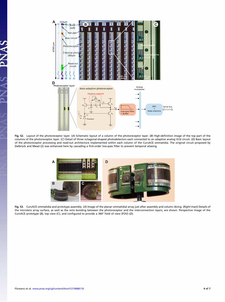
Fig. S2. Layout of the photoreceptor layer. (A) Schematic layout of a column of the photoreceptor layer. (B) High-definition image of the top part of thecolumns of the photoreceptor layer. (C) Detail of three octagonal-shaped photodetectors each connected to an adaptive analog VLSI circuit. (D) Basic layoutof the photoreceptor processing and read-out architecture implemented within each column of the CurvACE ommatidia. The original circuit proposed byDelbrück and Mead (2) was enhanced here by cascading a first-order low-pass filter to prevent temporal aliasing.
Fig. S3. CurvACE ommatidia and prototype assembly. (A) Image of the planar ommatidial array just after assembly and column dicing. (Right Inset) Details ofthe microlens array surface, as well as the wire bonding between the photoreceptor and the interconnection layers, are shown. Perspective image of theCurvACE prototype (B), top view (C), and configured to provide a 360° field of view (FOV) (D).
Floreano et al. www.pnas.org/cgi/content/short/1219068110 4 of 7
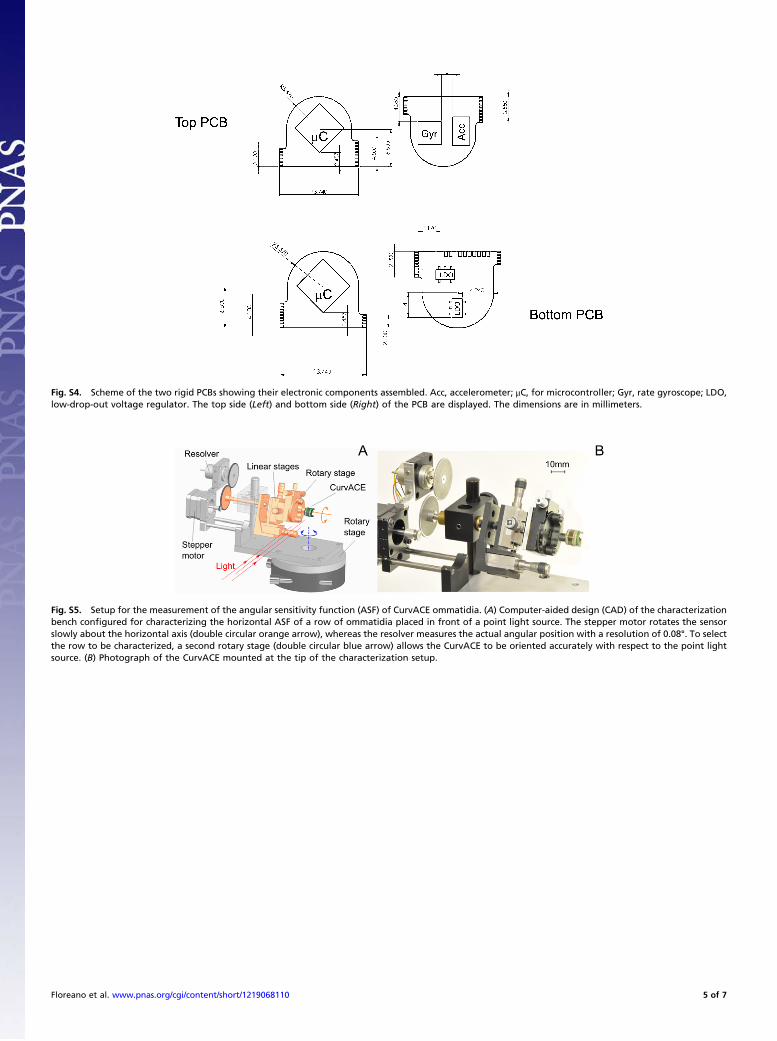
Fig. S4. Scheme of the two rigid PCBs showing their electronic components assembled. Acc, accelerometer; μC, for microcontroller; Gyr, rate gyroscope; LDO,low-drop-out voltage regulator. The top side (Left) and bottom side (Right) of the PCB are displayed. The dimensions are in millimeters.
Fig. S5. Setup for the measurement of the angular sensitivity function (ASF) of CurvACE ommatidia. (A) Computer-aided design (CAD) of the characterizationbench configured for characterizing the horizontal ASF of a row of ommatidia placed in front of a point light source. The stepper motor rotates the sensorslowly about the horizontal axis (double circular orange arrow), whereas the resolver measures the actual angular position with a resolution of 0.08°. To selectthe row to be characterized, a second rotary stage (double circular blue arrow) allows the CurvACE to be oriented accurately with respect to the point lightsource. (B) Photograph of the CurvACE mounted at the tip of the characterization setup.
Floreano et al. www.pnas.org/cgi/content/short/1219068110 5 of 7
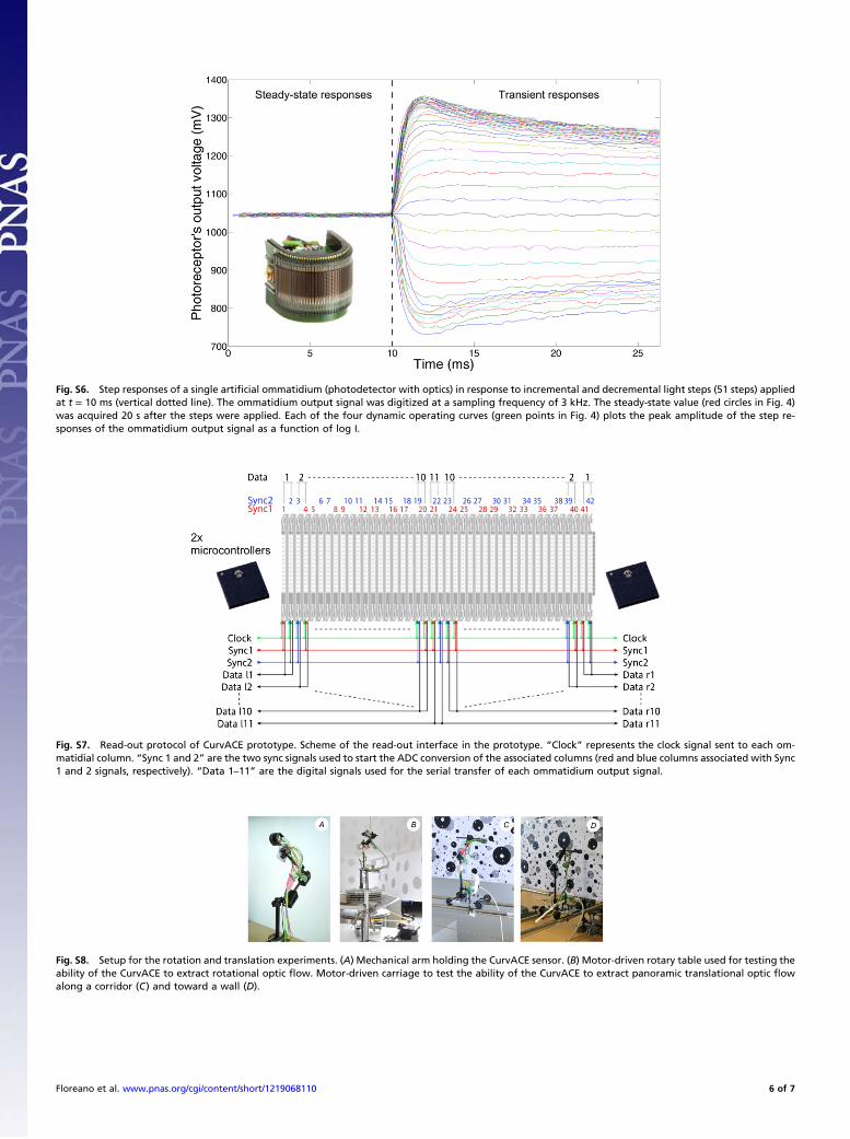
Fig. S6. Step responses of a single artificial ommatidium (photodetector with optics) in response to incremental and decremental light steps (51 steps) appliedat t = 10 ms (vertical dotted line). The ommatidium output signal was digitized at a sampling frequency of 3 kHz. The steady-state value (red circles in Fig. 4)was acquired 20 s after the steps were applied. Each of the four dynamic operating curves (green points in Fig. 4) plots the peak amplitude of the step re-sponses of the ommatidium output signal as a function of log I.
Fig. S7. Read-out protocol of CurvACE prototype. Scheme of the read-out interface in the prototype. “Clock” represents the clock signal sent to each om-matidial column. “Sync 1 and 2” are the two sync signals used to start the ADC conversion of the associated columns (red and blue columns associated with Sync1 and 2 signals, respectively). “Data 1–11” are the digital signals used for the serial transfer of each ommatidium output signal.
Fig. S8. Setup for the rotation and translation experiments. (A) Mechanical arm holding the CurvACE sensor. (B) Motor-driven rotary table used for testing theability of the CurvACE to extract rotational optic flow. Motor-driven carriage to test the ability of the CurvACE to extract panoramic translational optic flowalong a corridor (C) and toward a wall (D).
Floreano et al. www.pnas.org/cgi/content/short/1219068110 6 of 7
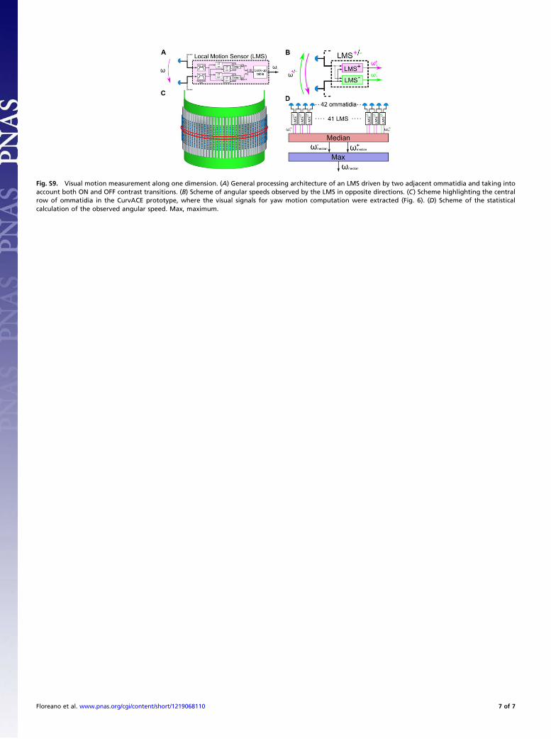
Fig. S9. Visual motion measurement along one dimension. (A) General processing architecture of an LMS driven by two adjacent ommatidia and taking intoaccount both ON and OFF contrast transitions. (B) Scheme of angular speeds observed by the LMS in opposite directions. (C) Scheme highlighting the centralrow of ommatidia in the CurvACE prototype, where the visual signals for yaw motion computation were extracted (Fig. 6). (D) Scheme of the statisticalcalculation of the observed angular speed. Max, maximum.
Floreano et al. www.pnas.org/cgi/content/short/1219068110 7 of 7