
Mini8TM Engineering Handbook - Sure Controls
332
Mini8 TM Engineering Handbook Mini8 Multi-loop process controller Version 2.50. HA028581/12 March 2013
Transcript of Mini8TM Engineering Handbook - Sure Controls

Mini8TM
Engineering Handbook
Mini8 Multi-loop process controller Version 2.50. HA028581/12 March 2013

© 2013 Eurotherm Limited
All rights are strictly reserved. No part of this document may be reproduced, modified, or transmitted in any form by any means, nor may it be stored in a retrieval system other than for the purpose to act as an aid in operating the equipment to which the document relates, without the prior, written permission of Eurotherm Limited.
- - - - - - - - - - - - - Eurotherm Limited pursues a policy of continuous development and product improvement. The specification in this document may therefore be changed without notice. The information in this document is given in good faith, but is intended for guidance only. Eurotherm Limited will accept no responsibility for any losses arising from errors in this document.

MINI 8 CONTROLLER: ENGINERING HANDBOOK
HA028581 Page 1 Issue 12 Mar 13 CN29751
Mini8 controller – Multi-Loop Process Controller Warning Back up Battery.......................................................................................................................................8
1. CHAPTER 1 INSTALLATION AND OPERATION ............................................................................................ 9 1.1 What Instrument Do I Have? ...................................................................................................................... 9 1.2 Mini8 Controller Ordering Code ............................................................................................................ 10 1.3 How to Install the Controller ................................................................................................................... 11
1.3.1 Dimensions ............................................................................................................................................................. 11 1.3.2 To Install the Controller ......................................................................................................................................... 11 1.3.3 Environmental Requirements ................................................................................................................................ 11
1.4 Electrical Connections ............................................................................................................................. 12 1.4.1 Power Supply .......................................................................................................................................................... 12 1.4.2 Fixed IO Connections ............................................................................................................................................ 13 1.4.3 Digital Communications Connections ................................................................................................................. 13 1.4.4 Configuration Port (CC) ........................................................................................................................................ 13 1.4.5 Screened Communications Cables ...................................................................................................................... 13 1.4.6 Modbus ................................................................................................................................................................... 14 1.4.7 DeviceNet / CANopen ........................................................................................................................................... 16 1.4.8 Enhanced DeviceNet Interface ............................................................................................................................. 18 1.4.9 Profibus DP ............................................................................................................................................................. 19 1.4.10 EtherNet (Modbus TCP) .................................................................................................................................... 20 1.4.11 EtherNet/IP ......................................................................................................................................................... 21 1.4.12 Thermocouple Input TC4 and TC8 .................................................................................................................. 22 1.4.13 RTD / PT100 Input RT4 ...................................................................................................................................... 22 1.4.14 Logic Input DI8 .................................................................................................................................................. 23 1.4.15 Logic Output DO8 ............................................................................................................................................. 23 1.4.16 Relay Output RL8 ............................................................................................................................................... 24 1.4.17 Analogue Output AO4 and AO8 ..................................................................................................................... 24 1.4.18 Current Transformer Input Module CT3 .......................................................................................................... 25
1.5 Adding or Replacing an IO Module. ...................................................................................................... 26 1.6 Mini8 Controller LED Indicators ............................................................................................................. 27
1.6.1 Status Indication for Enhanced DeviceNet .......................................................................................................... 28 1.6.2 Status Indication for EtherNet/IP .......................................................................................................................... 29
2. CHAPTER 2 USING THE MINI8 CONTROLLER ............................................................................................ 30 2.1 iTools ......................................................................................................................................................... 30
2.1.1 iTools OPC Open server ........................................................................................................................................ 30 2.2 Modbus, single register, SCADA addressing ....................................................................................... 30 2.3 Modbus (Floating Point) ......................................................................................................................... 31 2.4 Fieldbus ..................................................................................................................................................... 31 2.5 EtherNet (Modbus TCP) .......................................................................................................................... 31 2.6 Mini8 Controller Execution ..................................................................................................................... 31 2.7 The iTools Operator Interface ................................................................................................................ 32
2.7.1 Scanning ................................................................................................................................................................. 32 2.7.2 Browsing and Changing Parameter Values ......................................................................................................... 32
2.8 Recipe Editor ............................................................................................................................................ 34 2.8.1 Recipe Menu Commands ...................................................................................................................................... 34
2.9 OPCScope ................................................................................................................................................. 35 2.9.1 OPC Scope List Window Context Menu .............................................................................................................. 36 2.9.2 OPC Scope Chart Window .................................................................................................................................... 36 2.9.3 OPC Server ............................................................................................................................................................. 38
3. CHAPTER 3 CONFIGURATION USING ITOOLS .......................................................................................... 39 3.1 Configuration ............................................................................................................................................ 39
3.1.1 On-Line/Off-line Configuration............................................................................................................................. 39 3.2 Connecting a PC to the Mini8 Controller .............................................................................................. 39
3.2.1 Configuration Cable and Clip ............................................................................................................................... 39 3.2.2 Scanning ................................................................................................................................................................. 39
3.3 Cloning ...................................................................................................................................................... 40 3.4 Configuring the Mini8 Controller ........................................................................................................... 41
3.4.1 Function Blocks ...................................................................................................................................................... 41 3.4.2 Soft Wiring .............................................................................................................................................................. 42
3.5 Simple Worked Example ........................................................................................................................ 43

MINI8 CONTROLLER: ENGINEERING HANDBOOK
Page 2 HA028581 Issue 12 Mar 13
3.5.1 The I/O .................................................................................................................................................................... 43 3.5.2 Wiring ...................................................................................................................................................................... 46
3.6 Graphical Wiring Editor ........................................................................................................................... 49 3.6.1 Graphical Wiring Toolbar ...................................................................................................................................... 50 3.6.2 Function Block ........................................................................................................................................................ 50 3.6.3 Wire ......................................................................................................................................................................... 50 3.6.4 Block Execution Order ........................................................................................................................................... 50 3.6.5 Using Function Blocks ........................................................................................................................................... 50 3.6.6 Tooltips ................................................................................................................................................................... 51 3.6.7 Function Block State .............................................................................................................................................. 52 3.6.8 Using Wires ............................................................................................................................................................. 53 3.6.9 Using Comments .................................................................................................................................................... 54 3.6.10 Using Monitors................................................................................................................................................... 55 3.6.11 Downloading ..................................................................................................................................................... 55 3.6.12 Selections ........................................................................................................................................................... 55 3.6.13 Colours ............................................................................................................................................................... 56 3.6.14 Diagram Context Menu..................................................................................................................................... 56 3.6.15 Wiring Floats with Status Information .............................................................................................................. 57 3.6.16 Edge Wires ......................................................................................................................................................... 58
4. CHAPTER 4 MINI8 CONTROLLER OVERVIEW ........................................................................................... 59 4.1 Complete list of Function Blocks. ........................................................................................................... 60
5. CHAPTER 5 ACCESS FOLDER ...................................................................................................................... 61 6. CHAPTER 6 INSTRUMENT FOLDER ............................................................................................................. 62
6.1 Instrument / Enables ................................................................................................................................ 62 6.2 Instrument Options .................................................................................................................................. 63 6.3 Instrument / InstInfo ................................................................................................................................. 63 6.4 Instrument / Diagnostics ......................................................................................................................... 64
7. CHAPTER 7 I/O FOLDER ............................................................................................................................... 66 7.1 Module ID ................................................................................................................................................. 66
7.1.1 Modules .................................................................................................................................................................. 66 7.2 Logic Input ................................................................................................................................................ 67
7.2.1 Logic Input Parameters .......................................................................................................................................... 67 7.3 Logic Output ............................................................................................................................................. 68
7.3.1 Logic Out Parameters ............................................................................................................................................ 68 7.3.2 Logic Output Scaling ............................................................................................................................................. 69 7.3.3 Example: To Scale a Proportioning Logic Output.............................................................................................. 69
7.4 Relay Output ............................................................................................................................................. 70 7.4.1 Relay Parameters .................................................................................................................................................... 70
7.5 Thermocouple Input ................................................................................................................................ 71 7.5.1 Thermocouple Input Parameters .......................................................................................................................... 71 7.5.2 Linearisation Types and Ranges ........................................................................................................................... 73 7.5.3 CJC Type ................................................................................................................................................................ 73 7.5.4 Sensor Break Value ................................................................................................................................................ 74 7.5.5 Fallback ................................................................................................................................................................... 74 7.5.6 User Calibration (Two Point) ................................................................................................................................. 75 7.5.7 PV Offset (Single Point) .......................................................................................................................................... 75 7.5.8 Using TC4 or TC8 channel as a mV input ............................................................................................................ 76
7.6 Resistance Thermometer Input .............................................................................................................. 77 7.6.1 RT Input Parameters ............................................................................................................................................... 77 7.6.2 Linearisation Types and Ranges ........................................................................................................................... 78 7.6.3 Using RT4 as mA input........................................................................................................................................... 78
7.7 Analogue Output ..................................................................................................................................... 79 7.7.1 Example – 4 to 20mA Analogue Output .............................................................................................................. 79
7.8 Fixed IO ..................................................................................................................................................... 80 7.9 Current Monitor ........................................................................................................................................ 81
7.9.2 Single Phase Configurations ................................................................................................................................. 82 7.9.3 Three Phase Configuration ................................................................................................................................... 84 7.9.4 Parameter Configuration ....................................................................................................................................... 85 7.9.5 Commissioning ...................................................................................................................................................... 86 7.9.6 Calibration .............................................................................................................................................................. 88

MINI8 CONTROLLER: ENGINEERING HANDBOOK
HA028581 Page 3 Issue 12 Mar 13
8. CHAPTER 8 ALARMS ...................................................................................................................................... 89 8.1 Further Alarm Definitions ........................................................................................................................ 89 8.2 Analogue Alarms ...................................................................................................................................... 90
8.2.1 Analogue Alarm Types .......................................................................................................................................... 90 8.3 Digital Alarms ........................................................................................................................................... 91
8.3.1 Digital Alarm Types ................................................................................................................................................ 91 8.4 Alarm Outputs .......................................................................................................................................... 91
8.4.1 How Alarms are Indicated ..................................................................................................................................... 91 8.4.2 To Acknowledge an Alarm .................................................................................................................................... 91
8.5 Alarm Parameters..................................................................................................................................... 92 8.5.1 Example: To Configure Alarm 1 .......................................................................................................................... 93
8.6 Digital Alarm Parameters ........................................................................................................................ 94 8.6.1 Example: To Configure DigAlarm 1 .................................................................................................................... 94
8.7 Alarm Summary ........................................................................................................................................ 95 8.8 Alarm Log .................................................................................................................................................. 97
9. CHAPTER 9 BCD INPUT .................................................................................................................................. 98 9.1 BCD Parameters ....................................................................................................................................... 98
9.1.1 Example: To wire a BCD Input ............................................................................................................................. 99 10. CHAPTER 10 DIGITAL COMMUNICATIONS ............................................................................................. 100
10.1 Configuration Port (CC) ......................................................................................................................... 100 10.1.1 Configuration Communications Parameters ................................................................................................. 100
10.2 Field Communications Port (FC) .......................................................................................................... 100 10.2.1 Communications Identity ................................................................................................................................ 100
10.3 Modbus ................................................................................................................................................... 101 10.3.1 Modbus Connections ...................................................................................................................................... 101 10.3.2 Modbus Address Switch ................................................................................................................................. 101 10.3.3 Baud Rate ......................................................................................................................................................... 101 10.3.4 Parity ................................................................................................................................................................. 101 10.3.5 RX/TX Delay Time ............................................................................................................................................ 101
10.4 Modbus Broadcast Master Communications ..................................................................................... 102 10.4.1 Mini8 Controller Broadcast Master ................................................................................................................ 102 10.4.2 Modbus Parameters ........................................................................................................................................ 103
10.5 DeviceNet ............................................................................................................................................... 104 10.6 Enhanced DeviceNet Interface ............................................................................................................. 104
10.6.1 Address Switch ................................................................................................................................................ 104 10.6.2 Baud Switch...................................................................................................................................................... 104
10.7 Switch Position in iTools ........................................................................................................................ 104 10.7.1 DeviceNet Parameters .................................................................................................................................... 105
10.8 CANopen ................................................................................................................................................. 106 10.8.1 Instrument setup .............................................................................................................................................. 106 10.8.2 Mini8 Controller CANopen Features ............................................................................................................. 106 10.8.3 Communication Interface ............................................................................................................................... 107 10.8.4 Network Management (NMT) ......................................................................................................................... 108 10.8.5 Device Profile DS-404 ..................................................................................................................................... 109 10.8.6 Default PDOs ................................................................................................................................................... 109 10.8.7 Enabling and Disabling PDO Communications ........................................................................................... 112 10.8.8 Changing PDO Mapping ................................................................................................................................ 112 10.8.9 Remapping over the network ......................................................................................................................... 115 10.8.10 Enabling & Disabling PDO Change of State transmission. .......................................................................... 117 10.8.11 General Communication Objects .................................................................................................................. 117
10.9 Profibus ................................................................................................................................................... 122 10.9.1 Profibus Parameters ........................................................................................................................................ 122
10.10 EtherNet (Modbus TCP) ................................................................................................................... 123 10.10.1 Instrument setup .............................................................................................................................................. 123 10.10.2 Unit Identity ...................................................................................................................................................... 123 10.10.3 Dynamic Host Configuration Protocol (DHCP) Settings .............................................................................. 123 10.10.4 iTools Setup ..................................................................................................................................................... 124 10.10.5 EtherNet Parameters ....................................................................................................................................... 125
10.11 EtherNet/IP ......................................................................................................................................... 126 10.11.1 Feature Switch ................................................................................................................................................. 126 10.11.2 Configuration using iTools ............................................................................................................................. 126

MINI8 CONTROLLER: ENGINEERING HANDBOOK
Page 4 HA028581 Issue 12 Mar 13
10.11.3 EtherNet/IP Parameters .................................................................................................................................. 127 10.11.4 Input Definition Table ..................................................................................................................................... 128 10.11.5 Output Definition Table .................................................................................................................................. 129 10.11.6 Requested Packet Interval .............................................................................................................................. 129
10.12 Example - Connect mini8 Controller to Allen-Bradley PLC via EtherNet/IP .............................. 130 10.12.1 Installation ........................................................................................................................................................ 130 10.12.2 Setting Up The Link Between Windows And The Plc Network ................................................................... 130 10.12.3 Updating Firmware ......................................................................................................................................... 132 10.12.4 Completing the Link ........................................................................................................................................ 132 10.12.5 Creating a Network Scanner .......................................................................................................................... 134 10.12.6 Create or Load a Mini8 Controller Configuration ........................................................................................ 137 10.12.7 Run Mode ......................................................................................................................................................... 138 10.12.8 Monitor Parameters ......................................................................................................................................... 139 10.12.9 Status Indicators .............................................................................................................................................. 139 10.12.10 Mini8 Controller on an Ethernet/Ip Network ............................................................................................ 140 10.12.11 TROUBLESHOOTING ................................................................................................................................. 141
11. CHAPTER 11 COUNTERS, TIMERS, TOTALISERS, RT CLOCK ............................................................... 142 11.1 Counters .................................................................................................................................................. 142
11.1.1 Counter Parameters ........................................................................................................................................ 143 11.2 Timers ...................................................................................................................................................... 144
11.2.1 Timer Types...................................................................................................................................................... 144 11.2.2 On Pulse Timer Mode ..................................................................................................................................... 144 11.2.3 On Delay Timer Mode ..................................................................................................................................... 145 11.2.4 One Shot Timer Mode .................................................................................................................................... 146 11.2.5 Minimum On Timer or Compressor Mode ................................................................................................... 147 11.2.6 Timer Parameters ............................................................................................................................................ 148
11.3 Totalisers ................................................................................................................................................. 149 11.3.1 Totaliser Parameters ........................................................................................................................................ 150
11.4 Real Time Clock ...................................................................................................................................... 151 11.4.1 Real Time Clock Parameters ........................................................................................................................... 151
12. CHAPTER 12 APPLICATIONS ..................................................................................................................... 152 12.1 Humidity .................................................................................................................................................. 152
12.1.1 Overview .......................................................................................................................................................... 152 12.1.2 Temperature Control of an Environmental Chamber .................................................................................. 152 12.1.3 Humidity Control of an Environmental Chamber ......................................................................................... 152 12.1.4 Humidity Parameters ....................................................................................................................................... 153
12.2 Zirconia (Carbon Potential) Control..................................................................................................... 154 12.2.1 Temperature Control ...................................................................................................................................... 154 12.2.2 Carbon Potential Control ................................................................................................................................ 154 12.2.3 Sooting Alarm .................................................................................................................................................. 154 12.2.4 Automatic Probe Cleaning ............................................................................................................................. 154 12.2.5 Endothermic Gas Correction .......................................................................................................................... 154 12.2.6 Clean Probe ..................................................................................................................................................... 154 12.2.7 Probe Status ..................................................................................................................................................... 154 12.2.8 Zirconia Parameters......................................................................................................................................... 155
13. CHAPTER 13 INPUT MONITOR .................................................................................................................. 157 13.1 Description .............................................................................................................................................. 157
13.1.1 Maximum Detect ............................................................................................................................................. 157 13.1.2 Minimum Detect .............................................................................................................................................. 157 13.1.3 Time Above Threshold.................................................................................................................................... 157
13.2 Input Monitor Parameters ..................................................................................................................... 158 14. CHAPTER 14 LOGIC AND MATHS OPERATORS. .................................................................................... 159
14.1 Logic Operators ...................................................................................................................................... 159 14.1.1 Logic 8 .............................................................................................................................................................. 159 14.1.2 2 input Logic Operations ................................................................................................................................ 160 14.1.3 Logic Operator Parameters ............................................................................................................................ 161
14.2 Eight Input Logic Operators ................................................................................................................. 162 14.3 Maths Operators .................................................................................................................................... 163
14.3.1 Math Operations .............................................................................................................................................. 164 14.3.2 Math Operator Parameters ............................................................................................................................. 165 14.3.3 Sample and Hold Operation .......................................................................................................................... 166
14.4 Multiple Input Operator Block ............................................................................................................. 167 14.4.1 Cascaded operation ........................................................................................................................................ 168

MINI8 CONTROLLER: ENGINEERING HANDBOOK
HA028581 Page 5 Issue 12 Mar 13
14.4.2 Fallback Strategy ............................................................................................................................................. 168 14.4.3 Multiple Input Operator Block Parameters ................................................................................................... 169
14.5 Eight Input Analog Multiplexers .......................................................................................................... 170 14.5.1 Multiple Input Operator Parameters.............................................................................................................. 170 14.5.2 Fallback ............................................................................................................................................................ 170
15. CHAPTER 15 INPUT CHARACTERISATION............................................................................................... 171 15.1 Input Linearisation ................................................................................................................................. 171
15.1.1 Compensation for Sensor Non-Linearities .................................................................................................... 172 15.1.2 Input Linearisation Parameters ....................................................................................................................... 173
15.2 Polynomial .............................................................................................................................................. 174 16. CHAPTER 16 LOAD ...................................................................................................................................... 176
16.1 Load Parameters .................................................................................................................................... 176 17. CHAPTER 17 CONTROL LOOP SET UP ..................................................................................................... 177
17.1 What is a Control Loop? ........................................................................................................................ 177 17.2 Loop Parameters – Main ........................................................................................................................ 178 17.3 Loop Set up ............................................................................................................................................. 179
17.3.1 Types of Control Loop .................................................................................................................................... 179 17.4 PID Control .............................................................................................................................................. 180
17.4.1 Proportional Band ........................................................................................................................................... 181 17.4.2 Integral Term ................................................................................................................................................... 181 17.4.3 Derivative Term ............................................................................................................................................... 182 17.4.4 High and Low Cutback .................................................................................................................................... 183 17.4.5 Integral action and manual reset ................................................................................................................... 183 17.4.6 Relative Cool Gain ........................................................................................................................................... 183 17.4.7 Loop Break ....................................................................................................................................................... 184 17.4.8 Cooling Algorithm ........................................................................................................................................... 184 17.4.9 Gain Scheduling .............................................................................................................................................. 185 17.4.10 PID Parameters ................................................................................................................................................ 186 17.5.1 Loop Response ................................................................................................................................................ 187 17.5.2 Initial Settings ................................................................................................................................................... 187 17.5.3 Multi-zone applications. .................................................................................................................................. 188 17.5.4 Automatic Tuning ............................................................................................................................................ 189 17.5.5 Tune Parameters .............................................................................................................................................. 190 17.5.6 To Auto Tune a Loop - Initial Settings ............................................................................................................ 190 17.5.7 To Start Autotune ............................................................................................................................................ 191 17.5.8 Autotune and Sensor Break ............................................................................................................................ 191 17.5.9 Autotune and Inhibit ....................................................................................................................................... 191 17.5.10 Autotune and Gain Scheduling ...................................................................................................................... 191 17.5.11 Autotune from Below SP – Heat/Cool ............................................................................................................ 192 17.5.12 Autotune From Below SP – Heat Only ........................................................................................................... 193 17.5.13 Autotune at Setpoint – Heat/Cool .................................................................................................................. 194 17.5.14 Failure Modes .................................................................................................................................................. 195 17.5.15 Manual Tuning ................................................................................................................................................. 196 17.5.16 Manually Setting Relative Cool Gain .............................................................................................................. 196 17.5.17 Manually Setting the Cutback Values ............................................................................................................ 197
17.6 Setpoint Function Block ........................................................................................................................ 198 17.6.1 Setpoint Function Block .................................................................................................................................. 198 17.6.2 SP Tracking....................................................................................................................................................... 199 17.6.3 Manual Tracking .............................................................................................................................................. 199 17.6.4 Rate Limit .......................................................................................................................................................... 199 17.6.5 Setpoint Parameters ........................................................................................................................................ 199 17.6.6 Setpoint Limits ................................................................................................................................................. 201 17.6.7 Setpoint Rate Limit .......................................................................................................................................... 201 17.6.8 Setpoint Tracking ............................................................................................................................................ 202 17.6.9 Manual Tracking .............................................................................................................................................. 202
17.7 Output Function Block........................................................................................................................... 203 17.7.1 Output Limits ................................................................................................................................................... 206 17.7.2 Output Rate Limit ............................................................................................................................................ 207 17.7.3 Sensor Break Mode ......................................................................................................................................... 207 17.7.4 Forced Output ................................................................................................................................................. 207 17.7.5 Feedforward .................................................................................................................................................... 208 17.7.6 Effect of Control Action, Hysteresis and Deadband ..................................................................................... 209

MINI8 CONTROLLER: ENGINEERING HANDBOOK
Page 6 HA028581 Issue 12 Mar 13
18. CHAPTER 18 SETPOINT PROGRAMMER ................................................................................................. 210 18.1 INTRODUCTION..................................................................................................................................... 210
18.1.1 Time to Target Programmer ........................................................................................................................... 210 18.1.2 Ramp Rate Programmer ................................................................................................................................. 211
18.2 Mini8 Controller Programmer Block(s) ............................................................................................... 211 18.3 Segment Types ....................................................................................................................................... 212
18.3.1 Rate ................................................................................................................................................................... 212 18.3.2 Dwell ................................................................................................................................................................. 212 18.3.3 Step ................................................................................................................................................................... 212 18.3.4 Time .................................................................................................................................................................. 212 18.3.5 GoBack ............................................................................................................................................................. 212 18.3.6 Wait ................................................................................................................................................................... 213 18.3.7 End .................................................................................................................................................................... 213
18.4 Output Events ......................................................................................................................................... 214 18.4.1 Digital Events ................................................................................................................................................... 214 18.4.2 PV Event & User Value ..................................................................................................................................... 215 18.4.3 Time Event ....................................................................................................................................................... 216
18.5 Holdback ................................................................................................................................................. 218 18.5.1 Guaranteed Soak ............................................................................................................................................. 218
18.6 PID Select ................................................................................................................................................ 219 18.7 Program Cycles ...................................................................................................................................... 219
18.7.1 Servo ................................................................................................................................................................. 219 18.8 Power Fail Recovery .............................................................................................................................. 220
18.8.1 Ramp (Power fail during Dwell segments.) ................................................................................................... 220 18.8.2 Ramp (power fail during Ramp segments) .................................................................................................... 220 18.8.3 Ramp (power fail during Time-to-target segments) ..................................................................................... 220
18.9 To Run, Hold or Reset a Program ......................................................................................................... 221 18.9.1 Run .................................................................................................................................................................... 221 18.9.2 Reset ................................................................................................................................................................. 221 18.9.3 Hold .................................................................................................................................................................. 221 18.9.4 Skip segment ................................................................................................................................................... 221 18.9.5 Advance segment............................................................................................................................................ 222 18.9.6 Fast .................................................................................................................................................................... 222
18.10 PV Start ................................................................................................................................................ 222 18.11 Configuring the Programmer ........................................................................................................... 223 18.12 Programmer Run Status .................................................................................................................... 226 18.13 Creating a Program ........................................................................................................................... 227 18.14 Program Editor ................................................................................................................................... 227
18.14.1 Analog View ..................................................................................................................................................... 228 18.14.2 Digital View ...................................................................................................................................................... 230 18.14.3 Saving & Loading Programs ........................................................................................................................... 230 18.14.4 Printing a Program .......................................................................................................................................... 231
18.15 Wiring the Programmer Function Block. ........................................................................................ 232 19. CHAPTER 19 SWITCH OVER ....................................................................................................................... 234
19.1 Switch Over Parameters ........................................................................................................................ 235 20. CHAPTER 20 TRANSDUCER SCALING ...................................................................................................... 236
20.1 Auto-Tare Calibration ............................................................................................................................ 236 20.2 Load Cell ................................................................................................................................................. 237 20.3 Comparison Calibration ........................................................................................................................ 237 20.4 Transducer Scaling Parameters ............................................................................................................ 237
20.4.1 Parameter Notes .............................................................................................................................................. 239 20.4.2 Tare Calibration ............................................................................................................................................... 239 20.4.3 Load Cell .......................................................................................................................................................... 240 20.4.4 Comparison Calibration .................................................................................................................................. 240
21. CHAPTER 21 USER VALUES ........................................................................................................................ 241 21.1 User Value Parameters .......................................................................................................................... 241
22. CHAPTER 22 CALIBRATION ....................................................................................................................... 242 22.1 TC4 / TC8 User calibration .................................................................................................................... 242
22.1.1 Set Up ............................................................................................................................................................... 242 22.1.2 Zero Calibration ............................................................................................................................................... 242

MINI8 CONTROLLER: ENGINEERING HANDBOOK
HA028581 Page 7 Issue 12 Mar 13
22.1.3 Voltage Calibration ......................................................................................................................................... 242 22.1.4 CJC Calibration ............................................................................................................................................... 242 22.1.5 Sensor-Break Limit Check ............................................................................................................................... 242
22.2 To Return to TC4/TC8 Factory Calibration ......................................................................................... 243 22.3 RT4 User calibration ............................................................................................................................... 243
22.3.1 Set Up ............................................................................................................................................................... 243 22.3.2 Calibration ........................................................................................................................................................ 243
22.4 To Return to RT4 Factory Calibration .................................................................................................. 243 22.5 Calibration Parameters .......................................................................................................................... 244
23. CHAPTER 23 OEM SECURITY ..................................................................................................................... 245 23.1 Introduction ............................................................................................................................................ 245 23.2 Using OEM Security ............................................................................................................................... 245 23.3 Step 1 – View iTools OPC Server .......................................................................................................... 246 23.4 Step 2 – Create Custom Tags ................................................................................................................ 247 23.5 Step 3 – Activate OEM Security ............................................................................................................ 249 23.6 Step 4 – Deactivate OEM Security ....................................................................................................... 250 23.7 Erasing Memory ..................................................................................................................................... 250
24. APPENDIX A MODBUS SCADA TABLE ..................................................................................................... 251 24.1 Comms Table .......................................................................................................................................... 251 24.2 SCADA Table .......................................................................................................................................... 251
24.2.1 Programmer Address Ranges - Decimal ....................................................................................................... 282 24.2.2 Version 2.xx Programmer Addresses - Hexadecimal ................................................................................... 289
25. APPENDIX B DEVICENET PARAMETER TABLES ...................................................................................... 296 25.1 IO Re-Mapping Object .......................................................................................................................... 296 25.2 Application Variables Object................................................................................................................ 297
25.2.1 Table Modification........................................................................................................................................... 301 26. APPENDIX C CANOPEN PARAMETER TABLES........................................................................................ 302
26.1 Manufacturer Object – Pick List ............................................................................................................ 302 27. APPENDIX D VERSION 1.XX PROGRAMMER ........................................................................................... 306
27.1 Version 1.xx Parameter Tables ............................................................................................................. 306 27.1.1 Configuring the Programmer (V1.xx) ............................................................................................................. 306 27.1.2 To Select, Run, Hold or Reset a Program (V1.xx). ......................................................................................... 307 27.1.3 Creating a Program (V1.xx) ............................................................................................................................. 307 27.1.4 To Select, Run, Hold or Reset a Program (Version 1.xx) .............................................................................. 308
27.2 SCADA addresses for Programmer Version 1.xx ............................................................................... 308 28. APPENDIX E SAFETY AND EMC INFORMATION .................................................................................... 314 29. APPENDIX F TECHNICAL SPECIFICATION ............................................................................................... 317
29.1 Environmental Specification ................................................................................................................. 317 29.2 Network Communications Support ..................................................................................................... 317 29.3 Configuration Communications Support ............................................................................................ 317 29.4 Fixed I/O Resources ............................................................................................................................... 317 29.5 TC8 8-Channel and TC4 4-Channel TC Input Card ............................................................................ 318 29.6 DO8 8-Channel Digital Output Card ................................................................................................... 318 29.7 RL8 8-Channel Relay Output Card ....................................................................................................... 318 29.8 CT3 3-Channel Current-Transformer Input Card................................................................................ 319 29.9 Load Failure Detection .......................................................................................................................... 319 29.10 DI8 8-Channel Digital Input Card .................................................................................................... 319 29.11 RT4 Resistance Thermometer Input Card ....................................................................................... 319 29.12 AO8 8-Channel and AO4 4-Channel 4-20mA Output Card ......................................................... 320 29.13 Toolkit Blocks ..................................................................................................................................... 320 29.14 PID Control Loop Blocks ................................................................................................................... 320 29.15 Process Alarms ................................................................................................................................... 321 29.16 Setpoint Programmer ........................................................................................................................ 321 29.17 Recipes ................................................................................................................................................ 321
30. PARAMETER INDEX ....................................................................................................................................... 322

MINI8 CONTROLLER: ENGINEERING HANDBOOK
Page 8 HA028581 Issue 12 Mar 13
Issue Record of This Manual
Issue 6 includes Enhanced Devicenet Communications.
Issue 7 corrects terminal numbers in Example 2 section 7.9.2.1, adds references to iTools in sections 1.4.12 and 1.4.13 and adds to section 10.8 ‘Note: from July 09 CANopen option has been discontinued’.
Issue 8 clarifies and completes table 1.6.1.1 (Module status indication), and modifies the specification for Digital inputs in sections 29.4 and 29.10.
Issue 9 Section 1.4.7 thin trunk line length changed from 100m to 40m for baud rate of 1M.
Issue 10 adds two parameters ‘ServoToPV’ and ‘SPIntBal’ to the Setpoint Parameter List, update to order code, improve fallback description, timer and sample and hold diagrams.
Issue 11 adds EtherNet/IP.
Issue 12 adds the Battery Warning below:
! Warning
Back up Battery This instrument is fitted with a battery designed to retain configuration and other settings in the event of a failure of the instrument power supply.
This battery has an expected life of 10 years minimum at a nominal ambient working temperature (e.g. 25OC).
The battery life may be reduced if it is consistently operated in an elevated ambient temperature environment.
Maintenance Schedule A battery failure is only evident following a failure of the instrument power supply.
The battery should be replaced at regular intervals. Between 6 and 10 years is recommended depending on usage and operating temperature. The battery is not user serviceable, contact your local service centre to make suitable arrangements.
On older instruments contact your supplier to have the battery replaced prior to failure. The age of the instrument is shown on the side label. This contains a serial number, where the last four characters either show the week number and year of manufacture WW YY, or a date in the format UK YYWW.
It is important to maintain a record of instrument configurations or use Eurotherm iTools to make clone copies of fully working instruments. This is described in section 3.3. Store this securely as a back up to be used to restore the configuration.

MINI8 CONTROLLER: ENGINEERING HANDBOOK
HA028581 Page 9 Issue 12 Mar 13
Mini8 Multi-Loop Process Controller
1. Chapter 1 Installation and Operation 1.1 What Instrument Do I Have? Thank you for choosing this Mini 8 Controller.
The Mini8 controller is a compact DIN rail mounting multi-loop PID controller and data acquisition unit. It offers a choice of I/O and a choice of field communications.
The Mini8 controller mounts on 35mm Top Hat DIN Rail. It is intended for permanent installation, for indoor use only, and to be enclosed in an electrical panel or cabinet.
The Mini8 controller is pre-assembled in the factory to give the I/O required for the application as specified in the order code. With standard applications the Mini8 controller is also supplied configured. Alternatively, the Mini8 controller is configured using Eurotherm’s iTools configuration suite running on a personal computer.
All Safety & EMC information is in Appendix E.
The full Technical Specification is in Appendix F.
Whenever the symbol ☺ appears in this handbook it indicates a helpful hint

MINI8 CONTROLLER: ENGINEERING HANDBOOK
Page 10 HA028581 Issue 12 Mar 13
1.2 Mini8 Controller Ordering Code MINI8 1 2 3 4 5 6 7 8 9 10 11 12 13 14 15 16 17 18
Accessories SubMini8/Mechanics/Mtgplate Bulkhead mounting plate SubMini8/Cable/RJ45/0.5 Network 0.5m RS485 cable
SubMini8/Shunt/249R.1 2.49Ω 0.1% Burden resistor SubMini8/CD/Std Config tools and manuals
SubMini8/Resistor/Term/Mbus/RJ45 Modbus load terminator SubMini8/Cable/Config Config cable SubMini8/Resistor/Term/Pbus/RJ45 Profibus load terminator SubMini8/Manual/Inst Installation booklet SubMini8/Cable/RJ45/3.0 Network 3.0m RS485 cable SubMini8/Manual/Eng Engineering manual
17 Special XXXXX Standard YYNNNN Special number
Basic Product MINI8 Mini8 Controller
1 Control Loops
ACQ IO Acquisition only (not with EC8). No loops enabled.
4LP 4 Control loops 8LP 8 Control loops 16LP 16 Control loops
2 Programs 0PRG No Programs 1PRG 1 Profile – 50 programs
XPRG
Multi-profile – 50 programs If 4 loops are ordered, 4 programmers are supplied. If 8 or 16 loops are ordered 8 programmers are supplied
3 PSU VL 24Vdc
4 Communications MODBUS Non Isolated Modbus RTU slave ISOLMBUS Isolated Modbus RTU slave DEVICENET DeviceNet Slave
PBUSRJ45 Profibus Slave RJ45 (Profibus motherboard fitted)
PBUS9PIN Profibus Slave 9 pin D type (Profibus motherboard fitted)
ENETMBUS EtherNet Modbus TCP /IP Slave CANopen Slave (no longer available) DNETMI2 DeviceNet M12 connector slave ENETIP EtherNet/IP
5 Temperature Units C Centigrade F Fahrenheit
6-9 IO Slots 1, 2, 3, 4 XXX No module fitted TC4 4 Channel TC Input TC8 8 Channel TC Input RT4 4 Channel RTD input AO4 4 Channel 4-20mA output (slot 4 only) AO8 8 Channel 4-20mA output (slot 4 only) DO8 8 Channel logic output CT3 3 Channel CT input (only 1 CT per Mini8) RL8 8 Channel relay (slots 2, 3 only) DI8 8 Channel logic input
10 Application STD No configuration
EC8
8 Loop extrusion controller (EC8 is is a preconfigured version offering 8 control loops with heat/cool logic outputs). Requires 250 wires
Slot 1 = TC8 Slot 3 = DO8
Slot 2 = CT3 or XXX Slot 4 = DO8
FC8 8 Loop furnace controller with analogue outputs Requires 250 wires
Slot 1 = TC8 Slot 4 = AO8 11 Wires 30 30 User Wires 60 60 User Wires 120 120 User Wires 250 250 User Wires
12 Recipes None No Recipes RCP 8 Recipes
13 Manual ENG English GER German FRA French SPA Spanish ITA Italian
14 Configuration Software NONE No CD ITOOLS Itools CD & Mini8 controller documentation
15 Warranty XXXXX Standard WL005 Extended
16 Calibration Certificates XXXXX None CERT1 Certificate of conformity
CERT2 Factory input calibration per input. (5 point calibration)
18 Label XXXXX No custom label YYNNN Custom label

MINI8 CO
HA028581 Issue 12 Mar 13
1.3 How to Install the ControlleThis instrument is intended for permanent in
Select a location where minimum vibrations 122oF).
Please read the safety information, AppendiBooklet part number HA025497 for further i
1.3.1 Dimensions
Dimensio
A
B
C
Figu
1.3.2 To Install the Controller 1. Use 35mm symmetrical DI2. Mount the DIN Rail horizo
mounted in other orientat3. Hook the upper edge of th4. To remove use a screwdriv
released. 5. A second unit on the same6. A second unit mounted ab
the lower one and the bot
1.3.3 Environmental Requirements
Mini8 controller
Temperature
Humidity (non condensing)
Altitude
A
Allow a minimum of 2above and below eac
B
ONTROLLER: ENGINEERING HANDBOOK
er nstallation, for indoor use only, and to be enclosed in a
are present and the ambient temperature is within 0 a
ix E at the end of this manual, before proceeding and rnformation.
sion mm
A 108
B 124
C 115
ure 1-1: Mini8 Controller Dimensions
IN Rail to EN50022-35 x 7.5 or 35 x 15, ntally as indicated in Figure 1.1. The Mini8 controller isions. he DIN rail clip on the instrument on the top of the DINver to lever down the lower DIN rail clip and lift forward
e DIN rail may be mounted adjacent to the unit. bove or below the unit requires a gap of at least 25mmtom of the higher one.
Minimum Maximum
0°C 55°C
5% RH 95% RH
2000m
25mm ch unit
Allow a minimum of 25mm for terminals
and cables
C
Page 11
an electrical panel.
and 50oC (32 and
refer to the EMC
s NOT designed to be
N rail and push. d when the clip has
m between the top of

MINI8 CO
Page 12
1.4 Electrical Connections
The Mini8 controller is intended for operexcess of 42 volts must not b
A protective earth connection is required.
Do not replace the battery. Return to factory
Figure 1
1.4.1 Power Supply The power supply requires a supply betwee
24V Ø 24 V dc
24V Ø 24 V dc
0V Ø 0 V dc
GND Ø Ground
Connector terminals will accept wire sizes fr
Note: If the Min8 is used with the VT505 panover. The connectors are physically the saminto the Mini8 controller will short-circuit the
24V
24V
0V
GND
Power SUser Te
Power Supply Section 1.4.1
Fixed IO
Section 1.4.2
Instrument LEDs section 1.6
CommunicLEDs section 1.6
Communications connector
DeviceNet shown
ONTROLLER: ENGINEERING HANDBOOK
ration at safe low voltage levels, except the RL8 relay mbe applied to any terminals other than the RL8 relay m
y if replacement battery is required.
-2: Terminal Layout for Mini8 Controller
en 17.8 to 28.8 V dc, 15 watts maximum
om 0.2 to 2.5, 24 to 12 awg.
nel ensure that the power supply connectors cannot beme, but the electrical connections are not compatible. Pe 24 volt supply.
Power SupplyMale Connector
Supplyrminals
cations
6
I/O Slots I to 4 Sections 1.4.12 to 1.4.18
Communications settings
Communications Configuration port Section 3.2
HA028581 Issue 12 Mar 13
module. Voltages in module.
e mistakenly changed Plugging the connector

MINI8 CONTROLLER: ENGINEERING HANDBOOK
HA028581 Page 13 Issue 12 Mar 13
1.4.2 Fixed IO Connections These I/O are part of the power supply board and are always fitted.
Digital Inputs : ON requires +10.8V to +28.8V.
OFF requires -28.8V to +5V
+5V to +10.8v is undefined
Typical drive 2.5mA at 10.8V.
Relays contacts: 1 amp max, 42Vdc. These contacts are NOT rated for mains operation.
1.4.3 Digital Communications Connections Two communications connections are fitted – a Modbus Configuration port (RJ11) and a Fieldbus port.
The Fieldbus is either Modbus (2 x RJ45 ), DeviceNet, CANopen, Profibus, EtherNet Modbus TCP (10baseT) or EtherNet IP.
1.4.4 Configuration Port (CC) The configuration port (Modbus) is on an RJ11 socket. It is always fitted just to the right of the power supply connections. It is a point to point RS232 connection. Eurotherm supply a standard cable to connect a serial COM port on a computer to the RJ11 socket, part no. SubMin8/cable/config.
9 pin DF to PC COM port (RS232)
RJ11 Pin
Function
- 6 N/c
3 (Tx) 5 Rx
2 (Rx) 4 Tx
5 (0v) 3 0v (gnd)
2 N/c
1 Reserved
See also section 10.1
1.4.5 Screened Communications Cables Screened cables should be used. In order to reduce the effects of RF interference the transmission line should be grounded at both ends of the screened cable. However, care must be taken to ensure that differences in earth potentials do not allow circulating currents to flow as these can induce common mode signals in the data lines. Where doubt exists it is recommended that the screen (shield) be grounded at only one section of the network. This applies to all communications protocols.
Pin 1
Pin 6
Digital Input 1
Digital Input 2
Digital Input common
Relay A n/open
Relay A n/closed
Relay A common
Relay B n/open
Relay B n/closed
Relay B common
D1
D2
C
A1
A2
A3
B1
B2
B3

MINI8 CONTROLLER: ENGINEERING HANDBOOK
Page 14 HA028581 Issue 12 Mar 13
1.4.6 Modbus
For a full description of the installation of a communications link, including line matching resistors, see Eurotherm 2000 series communications handbook, part no. HA026230.
For Modbus operation see section 10.3.
Figure 1-3: Front Panel Layout Modbus
1.4.6.1 Modbus Connectors Two RJ45 sockets are provided – one for the incoming connection, the second to loop onto the next instrument or for a line terminator, see Figure 1-4.
RJ45 pin 3 wire 5 wire 8 A RxA
7 B RxB
6 Ground Ground
5
4
3 Ground Ground
2 A TxA
1 B TxB
The RS485 standard allows one or more instruments to be connected (multi dropped) using a two wire connection, with cable length of less than 1200m. 31 instruments and one master may be connected.
To use RS485, buffer the RS232 port of the PC with a suitable RS232/RS485 converter. The Eurotherm Controls KD485 Communications Adapter unit is recommended for this purpose. The use of a RS485 board built into the computer is not recommended since this board may not be isolated, which may cause noise problems or damage to the computer, and the RX terminals may not be biased correctly for this application.
Either cut a patch cable and connect the open end to the KD485 converter or, using twin screened cable, crimp an RJ45 plug on the Mini8 controller end.
The communication line must be daisy chained from device to device and, if the communications line is more than a metre or two long, it must be correctly terminated. A Modbus terminator containing the correct termination resistors is available from Eurotherm, order code:
SubMin8/RESISTOR/MODBUS/RJ45. The Modbus terminator is BLACK.
See also the 2000 series Communications Handbook, part number HA026230, available on www.eurotherm.co.uk. for further information on digital communications.
Pin 8
Pin 1
Address Switch See section 10.3.2
LED Indicators See section 1.6
Two RJ45 Sockets
RN CC FC P A B
24V
24V
0V
GND
D1 D2 C 1 2 3 1 2 3
A
B
FC
1 2 3 4
1 2 3 4
H H H H
A A A A
P P P P
I I I I
i n v e n s y s
E u r o t h e r m M o d B u s M i n i 8
CCConfiguration Port See section 1.4.4
1 2
3
4
5 6
7
8
ON

MINI8 CONTROLLER: ENGINEERING HANDBOOK
HA028581 Page 15 Issue 12 Mar 13
Mini8 Master
RS422
RS485 4-wire
Rx+
Rx-
Tx+
Tx- Slave 1
RS422
RS485 4-wire
Rx+
Rx-
Tx+
Tx-
Com Com
1.4.6.2 Modbus Interconnections - RS485
Figure 1-4: RS485 two-wire Connections
For the 4 wire connection the TxA and TxB are not connected to RxA and RxB but connected separately through another twisted pair.
1.4.6.3 Wiring Connections for Modbus Broadcast Communications The Digital Communications module for the master must be the Field Comms and is only RS485/RS422. RS232 is not available.
The Digital Communications module for the slave can be the Config port (RS232 only) or the Field Comms port (Not RS232).
Standard patch cables cannot be used, as the connections do not ‘cross over.’ Wire using twisted pair(s) cable and crimp on the appropriate RJ45 or RJ11 plug.
RS485 2-wire
Connect A (+) in the master to A (+) of the slave
Connect B (-) in the master to B (-) of the slave
This is shown diagrammatically below
Figure 1-5: Rx/Tx Connections RS485 2-wire
RS422, RS485 4-wire
Rx connections in the master are wired to Tx connections of the slave
Tx connections in the master are wired to Rx connections of the slave
Figure 1-6: Rx/Tx Connections for RS422, RS485 4-wire
220 Ohm termination resistor on the Rx of the converter unit
Type KD485 converter
RS232
RS485
Mini8 no. 1
Modbus
Terminator
RJ45 Patch cables Com Rx Tx
RxA
RxBCom
TxA
TxB
Mini8 no. n
Screened cable, see
section 1.4.5
Mini8 Master RS485
B (-)
A (+) Slave 1
RS485
B (-)
A (+)
Com Com

MINI8 CONTROLLER: ENGINEERING HANDBOOK
Page 16 HA028581 Issue 12 Mar 13
1.4.7 DeviceNet / CANopen
Instruments supplied after July 2009 no longer support DeviceNetTM CAN interface, CANopen V4.02 CAN interface and Enhanced DeviceNetTM . Information is included here to cover instruments supplied previously with CANopen.
DeviceNet and CANopen both use a 5 way, 5.08mm pitch, connector/screw terminal. The DeviceNet bus is powered (24V) from the system network, not from the instrument. The Mini8 controller requirement is a load of around 100mA. For the address switch see section 10.5.
Figure 1-7: Front Panel Layout Devicenet
1.4.7.1 DeviceNet Connector
Pin Legend Function
5 V+ V+
4 CH CAN HIGH
3 DR DRAIN
2 CL CAN LOW
1 V- V-
Mini8 controller Label Colour Description
V+ Red Network power positive terminal. Connect the red wire of the DeviceNet / CANopen cable here. If the network does not supply the power, connect the positive terminal of an external 11-25 Vdc power supply.
CAN_H White CAN_H data bus terminal. Connect the white wire of the DeviceNet / CANopen cable here.
SHIELD None Shield/Drain wire connection. Connect the DeviceNet cable shield here. To prevent ground loops, the network should be grounded in only one location.
CAN_L Blue CAN_L data bus terminal. Connect the blue wire of the DeviceNet / CANopen cable here.
V- Black Network power negative terminal. Connect the black wire of the DeviceNet / CANopen cable here. If the DeviceNet network does not supply the power, connect the negative terminal of an external 11-25 Vdc power supply.
The DeviceNet specification states that the bus terminators of 121 ohm should not be included as any part of a master or slave. They are not supplied but should be included in the cabling between CAN_H and CAN_L where required.
The CANopen Cabling and Connector Pin Assignment specification specifies that the minimum termination resistance is 118 ohm with the following guidelines. They are not supplied but should be included in the cabling where required.
Bus length (m) Termination resistance (ohms)
0 – 40 124
40 – 100 150 - 300
1
5
Address Switch See section 10.5.
LED Indicators See section1.6
DeviceNet Connector
RN CC FCP A B
24V
24V
0V
GND
D1D2 C 1 2 3 1 2 3
A
B
FC
1 2 3 4
1 2 3 4
H H H H
A A A A
P P P P
I I I I
i n v e n s y s
E u r o t h e r m D e v i c e N e t M i n i 8
CCConfiguration Port See section 1.4.4
1 2
3
4
5 6
7
8
ON

MINI8 CONTROLLER: ENGINEERING HANDBOOK
HA028581 Page 17 Issue 12 Mar 13
1.4.7.2 Network Length
Network length depends on Baud rate:-
Network Length Varies w/speed, up to 4000m possible w/repeaters
Baud Rate 125 250 500 1M (CANopen)
Thin trunk 100m (328ft) 100m (328ft) 100m (328ft) 40m
Max drop 6m (20ft) 6m (20ft) 6m (20ft) 6m(20ft)
Cumulative drop 156m (512ft) 78m (256ft) 39m (128ft) 19m (64ft)
1.4.7.3 Typical DeviceNet / CANopen Wiring Diagram
Note:
The DeviceNet network is powered by an external independent 24V supply which is separate from the internal powering of the individual controllers.
Note: Power taps are recommended to connect the DC power supply to the DeviceNet trunk line. Power taps include:
A Schottky Diode to connect the power supply V+ and allows for multiple power supplies to be connected.
2 fuses or circuit breakers to protect the bus from excessive current which could damage the cable and connectors.
The earth connection, HF, to be connected to the main supply earth terminal at one point only.
See also the DeviceNet Communications Handbook HA027506
DeviceNet Power Supply
24Vdc (+/- 1%)
250mV p-p Ripple
max
DeviceNet Trunk Cable
V+
V-
Gnd
V- Shield V+
↑ Further Devices
Mini8_1
Drop Line
MASTER
Drop Line
Drop Line
* 121 1% 1/4W terminating resistor must be connected across the blue and white wires at each end of the DeviceNet trunk cable.
Note: this resistor is sometimes included in the master or other devices but should only be switched into circuit on the last device on the trunk cable.
Further Devices ↓
Mini8_2
CAN-L CAN-H
V+
CAN_H
DRAIN
Can_L
V-
V+
CAN_H
DRAIN
Can_L
V-
*
*

MINI8 CONTROLLER: ENGINEERING HANDBOOK
Page 18 HA028581 Issue 12 Mar 13
1.4.8 Enhanced DeviceNet Interface This version of DeviceNet has been added for use in the Semiconductor industry. Configuration for both versions is the same and is described in the DeviceNet Handbook HA027506 which can be downloaded from www.eurotherm.com.
The Enhanced DeviceNet interface uses a different connector, as described below, but cabling, cable specification and termination are the same as described in the previous section.
Figure 1-8: Enhanced DeiceNet Panel Layout
1.4.8.1 Enhanced DeviceNet Connector The 5-way connector shown in the previous section is replaced by a ‘Micro-Connect’ circular 5-pin M12 male connector mounted in the module.
Pin Legend Function
5 CAN_L CAN LOW
4 CAN_H CAN HIGH
3 V- V-
2 V+ V+
1 DR DRAIN
1.4.8.2 Switches and LED Indicators The Enhanced DeviceNet interface also uses different Module and Network Status indicators, address and baud rate switches.
To set the Address and Baud Rate, see section 10.6.
For Module and Network Status indication see section 1.6.1.
1 2
3 4
Plug Key
View from front
5
Address Switch See section 10.6.1
LED Indicators See section 1.6
DeviceNet Connector
Baud Rate Switch, see section 10.6.2
Specific LED Indicators for Enhanced DeviceNet.
See section 1.6.1
Configuration Port See section 1.4.4

MINI8 CONTROLLER: ENGINEERING HANDBOOK
HA028581 Page 19 Issue 12 Mar 13
1.4.9 Profibus DP Two Profibus communications board options are available for the Mini8 controller.
1. Standard Profibus 3 wire RS485 9 pin D connector intended for installation using standard Profibus cabling. Note that in this arrangement line terminations must be catered for in the cabling.
2. Profibus 3 wire RS485 via 2 paralleled RJ45 sockets. The front panel layout for this version is the same as Modbus (Figure 1-3). Instruments may be daisy chained using suitable RJ45 cables and an RJ45 termination plug is available to terminate the line.
Figure 1-9: Profibus Panel Layout - Standard D Connector
1.4.9.1 Profibus Interface (D-Type Connector)
Connector: 9-Way D-Type, R/A, Female, 4-40 UNC Studs:
Pin Function
Terminations must be included in the cabling.
1 Shield (Case) 2 N/C 3 RxD/TxD+ P (B) 4 N/C 5 GND (0V) 6 VP (+5V) 7 N/C 8 RxD/TxD- N (A) 9 N/C
1.4.9.2 Profibus Interface (RJ45 Connector)
Connector: Two RJ45, parallel connected (for daisy-chain):
Pin 3-Wire One connector may be used to terminate line using SubMini8/Term/Profibus/RJ45
This terminator is grey.
8 (do not use) 7 (do not use) 6 VP (+5V) 5 4 3 GND 2 RxD/TxD+ P (B) 1 RxD/TxD- N (A)
8
1
Address Switch See section 10.9
LED Indicators See section 1.6
Standard Profibus Connector
RN CC FCP A B
24V
24V
0V
GND
D1D2 C 1 2 3 1 2 3
A
B
FC
1 2 3 4
1 2 3 4
H H H H
A A A A
P P P P
I I I I
i n v e n s y s
E u r o t h e r m P r o f i b u s M i n i 8
CCConfiguration Port See section 1.4.4
1 2
3
4
5 6
7
8
ON

MINI8 CONTROLLER: ENGINEERING HANDBOOK
Page 20 HA028581 Issue 12 Mar 13
1.4.10 EtherNet (Modbus TCP) The EtherNet connection uses standard Cat5E patch cables (RJ45). These would be used with a 10BaseT hub to create a network.
A crossover patch cable may be used ‘point-to-point’ i.e. to connect a single instrument directly to a PC.
Figure 1-10: EtherNet TCP Front Panel Layout
1.4.10.1 Connector: RJ45:
Pin Function 8 7 6 RX- 5 4 3 RX+ 2 TX- 1 TX+
8
1
Network activity (yellow)
Controller communicating (green)
Configuration Port See section 1.4.4
Address Switch See section 10.10.3
LED Indicators See section 1.6
RJ45 Socket
RN CC FCP A B
24V
24V
0V
GND
D1D2 C 1 2 3 1 2 3
A
B
FC
1 2 3 4
1 2 3 4
H H H H
A A A A
P P P P
I I I I
i n v e n s y s
E u r o t h e r m M O D B U S / T C P M i n i 8
CC
1 2
3
4
5 6
7
8
ON

MINI8 CONTROLLER: ENGINEERING HANDBOOK
HA028581 Page 21 Issue 12 Mar 13
1.4.11 EtherNet/IP
Figure 1-11: EtherNet/IP Front Panel Layout
1.4.11.1 Connector: RJ45:
This is the same as the connector shown above in section 1.4.10
Note: Screened cable should be used, see section 1.4.5 for further details.
Pin Function 8 7 6 RX- 5 4 3 RX+ 2 TX- 1 TX+
8
1
Network activity (yellow)
Controller communicating (green)
Feature Switch See section 10.11.1
LED Indicators See section 1.6
RJ45 Socket
RN CC P A B
24V
24V
0V
GND
D1D2 C 1 2 3 1 2 3
A
B
FC
1 2 3 4
1 2 3 4
H H H H
A A A A
P P P P
I I I I
i n v e n s y s
E u r o t h e r m E t h e r N e t / I P M i n i 8
CCConfiguration Port See section1.4.4
NET MODStatus Indication See section 1.6.2
1 2
3
4
5 6
7
8
ON

MINI8 CONTROLLER: ENGINEERING HANDBOOK
Page 22 HA028581 Issue 12 Mar 13
1.4.12 Thermocouple Input TC4 and TC8
The TC8 thermocouple module takes 8 thermocouples.
The TC4 module takes 4 thermocouples.
They may be placed in any slot in the Mini8 controller.
Up to 4 modules may be fitted in a Mini8 controller.
Each input can be configured to any thermocouple type or a linear mV input.
Note: Configuration of Mini8 Controller is performed using ‘iTools’ configuration suite running on a personal computer.
See subsequent chapters in this manual and specifically example 1 given in section 3.5.1 for further information.
The TC4 module offers TC1 to TC4, on terminals A to H.
1.4.13 RTD / PT100 Input RT4
The RT4 module provides 4 RTD inputs for 2, 3 or 4 wire connections.
Up to 4 modules may be fitted in a Mini8 controller and they may be placed in any slot.
Each input can be configured for any resistive sensor up to 600 ohms. Standard linearisation is available for PT100.
Note: Configuration of Mini8 Controller is performed using ‘iTools’ configuration suite running on a personal computer.
See subsequent chapters in this manual and specifically example 2 given in section 3.5.1 for further information.
☺ Tip: Spare RT4 input channels may be configured as mA inputs using a 2.49 ohm resistor, order code SubMini8/resistor/Shunt/249R.1.
See section 7.6.3 for configuration.
2-wire 3-wire 4-wire
CH1 Current +
CH1 Sense +
CH1 Sense -
CH1 Current -
CH2 Current +
CH2 Sense +
CH2 Sense -
CH2 Current +
A
B
C
D
E
F
G
H
2-wire 3-wire 4-wire
CH3 Current +
CH3 Sense +
CH3 Sense -
CH3 Current -
CH4 Current +
CH4 Sense +
CH4 Sense -
CH4 Current +
I
J
K
L
M
N
O
P
A
B
C
D
E
F
G
H
TC1+
TC1-
TC2+
TC2-
TC3+
TC3-
TC4+
TC4-
I
J
K
L
M
N
O
P
TC5+
TC5-
TC6+
TC6-
TC7+
TC7-
TC8+
TC8-
2.49 ohm
A
B
C
D
E
F
G
H
mA in
_
+

MINI8 CONTROLLER: ENGINEERING HANDBOOK
HA028581 Page 23 Issue 12 Mar 13
1.4.14 Logic Input DI8
The DI8 module provides 8 logic inputs.
They may be placed in any slot in the Mini8 controller.
Up to 4 modules may be fitted in a Mini8 controller.
Digital Inputs : ON requires +10.8V to +28.8V.
OFF requires -28.8V to +5V
+5V to +10.8v is undefined
Typical drive 2.5mA at 10.8V.
.
1.4.15 Logic Output DO8
The DO8 module provides 8 logic outputs.
They may be placed in any slot in the Mini8 controller.
Up to 4 may be fitted in a Mini8 controller.
Each output can be configured to Time Proportioning or On/Off.
Supply In + (A,B,I,J) are all linked internally.
Supply In – (G,H,O,P) are all linked internally.
D1+
D1-
D2+
D2-
D3+
D3-
D4+
D4-
A
B
C
D
E
F
G
H
D5+
D5-
D6+
D6-
D7+
D7-
D8+
D8-
I
J
K
L
M
N
O
P
+24V 0V
+24V 0V
+24V 0V
+24V 0V
+24V 0V
+24V 0V
+24V 0V
+24V 0V
+
–
Supply In +
Supply In +
OP1 +
OP2 +
OP3 +
OP4 +
Supply & OP -
Supply & OP -
A
B
C
D
E
F
G
H
I
J
K
L
M
N
O
P
Supply In +
Supply In +
OP1 +
OP2 +
OP3 +
OP4 +
Supply & OP -
Supply & OP -
SSR 1 +
–
SSR 8
SSRs 2 to 7
24V
24V
0V
0V

MINI8 CONTROLLER: ENGINEERING HANDBOOK
Page 24 HA028581 Issue 12 Mar 13
1.4.16 Relay Output RL8
The RL8 module provides 8 relay outputs.
Up to 2 modules may be fitted and in slots 2 and/or 3 only
Relay contacts for full contact life:
Maximum 264V ac 2amps with snubber fitted.
Minimum 5V dc, 10mA
Snubbers are used to prolong the life of relay contacts and to reduce interference when switching inductive devices such as contactors or solenoid valves. If the relay is used to switch a device with a high impedance input, no snubber is necessary.
All relay modules are fitted internally with a snubber since these are generally required to switch inductive devices. However, snubbers pass 0.6mA at 110V and 1.2mA at 230Vac, which may be sufficient to hold on high impedance loads. If this type of device is used it will be necessary to remove the snubber from the circuit.
The relay module has to be removed from the instrument, see section 1.5. The snubber is removed from the relay module by inserting a screwdriver into one of the pair of slots either side of the track of each snubber network. Twist the screwdriver to break out this track between the slots.
This action is not reversible.
1.4.17 Analogue Output AO4 and AO8
The AO8 modules provides 8 analogue outputs and the AO4 provides 4 analogue outputs.
Each output is configurable within 0 to 20 mA , max load 360 ohm.
The AO4 offers OP1 to OP4 on terminals A to H.
Only one module may be fitted and in slot 4 only.
☺ Tip: A 0 to 10 volt output can be obtained by scaling the drive to 0 to 10mA and fitting an external 1kohm resistor (for example). Low load impedance may alter the results but this can be corrected by adjusting the output range accordingly.
RLY5 A
RLY5 B
RLY6 A
RLY6 B
RLY7 A
RLY7 B
RLY8 A
RLY8 B
A
B
C
D
E
F
G
H
I
J
K
L
M
N
O
P
RLY1 A
RLY1 B
RLY2 A
RLY2 B
RLY3 A
RLY3 B
RLY4 A
RLY4 B
A
B
C
D
E
F
G
H
I
J
K
L
M
N
O
P
OP1 +
OP1 -
OP2 +
OP2 -
OP3+
OP3 -
OP4 +
OP4 -
OP5 +
OP5 -
OP6 +
OP6 -
OP7+
OP7 -
OP8 +
OP8 -

MINI8 CONTROLLER: ENGINEERING HANDBOOK
HA028581 Page 25 Issue 12 Mar 13
1.4.18 Current Transformer Input Module CT3
This provides inputs for 3 current transformers. The heater load cables are threaded through the transformers. Each input is 50mA max into 5 ohms.
The current transformers provide channel isolation; there is no channel to channel isolation in the module.
It is recommended that the current transformer is fitted with a voltage limiting device such as two back to back zener diodes between 3 and 10 volts, rated for 50mA.
There are 3 CT inputs, one for each phase. Up to a maximum of 16 heaters may be threaded through the CTs but with a further limit of 6 heater wires through each individual CT.
See Section 7.9 for typical circuit arrangements.
A
B
C
D
E
F
G
H
I
J
K
L
M
N
O
P
Reserved
Reserved
Reserved
Reserved
Reserved
Reserved
Reserved
Reserved
In 1 A
In 1 B
No connection
In 2 A
In 2 B
No connection
In 3 A
In 3 B
CT1
CT2
CT3

MINI8 CO
Page 26
1.5 Adding or Replacing an IO
Modules contain static sensitive electronic on an earthed mat with an earthed wrist st
the
Figure 1-12
1. Remove all connectors. 2. Remove the 2 screws indic3. Remove the cover. 4. If removing a module gent5. Insert the new module care
connector with its mate onmechanical support rather
6. Once you are certain the twforce.
7. Replace cover and the 2 co8. Replace all connectors ont
Remove screw
ONTROLLER: ENGINEERING HANDBOOK
Module.
devices. Take full antistatic protection when replacingtrap. Avoid touching components, keep fingers on thee edge of the printed circuit boards.
2: Mini8 controller Cover Retaining Screws
cated above
tly prise it out using the green connectors. efully using the guides on the side of the case to help t
n the motherboard. This requires great care as the guidr than being plug in guides. wo connectors are lined up, push the module gently in
over screws. to their correct modules.
Remove sc
HA028581 Issue 12 Mar 13
g modules by working e green connectors or
to line up the lower des provide
nto place. Do NOT
crew

MINI8 CONTROLLER: ENGINEERING HANDBOOK
HA028581 Page 27 Issue 12 Mar 13
1.6 Mini8 Controller LED Indicators
Two sets of 3 LED indicators on the front panel indicate the power, the state of the output relays, the status of the Mini8 controller and communications activity. LEDs P, A, B, RN, CC are common to all Mini8 controllers. FC is replaced by Network and Module Status LEDs when DeviceNet or EtherNet/IP communications modules are fitted.
Note: The EtherNet connector itself has two in-built LEDs (sections 1.4.10 and 1.4.11):
Green = network activity
Yellow = Mini8 controller communicating
The Mini8 controller is controlling normally ONLY if the green RN LED is permanently ON.
Note: In iTools the parameter ‘Comms Network Status’ is available enumerated as shown in the following table. The enumerations correspond to the FC indicator as shown in the final column:-
‘Status’ Parameter Enumeration
Meaning Corresponding FC LED
RUNNING (0) Network connected and running On INIT (1) Network initialising Off READY (2) DeviceNet traffic detected but not for this address Blinking OFFLINE (3) No DeviceNet traffic detected Off
Legend P A B LED Green Red Red Function Indicates 24V Relay A state Relay B state OFF No power De-energised De-energised ON Powered Energised Energised
Legend RN CC FC Modbus/Profibus DeviceNet/CANopen Ethernet*
LED Green Green Green Green Green Function Indicates
run mode Indicates Configuration
Field comms activity
Status Field comms activity
OFF Not running -- Offline Offline No port traffic Blinking Standby Config traffic Traffic Ready Port traffic excluding
local housekeeping ON Running -- Connected
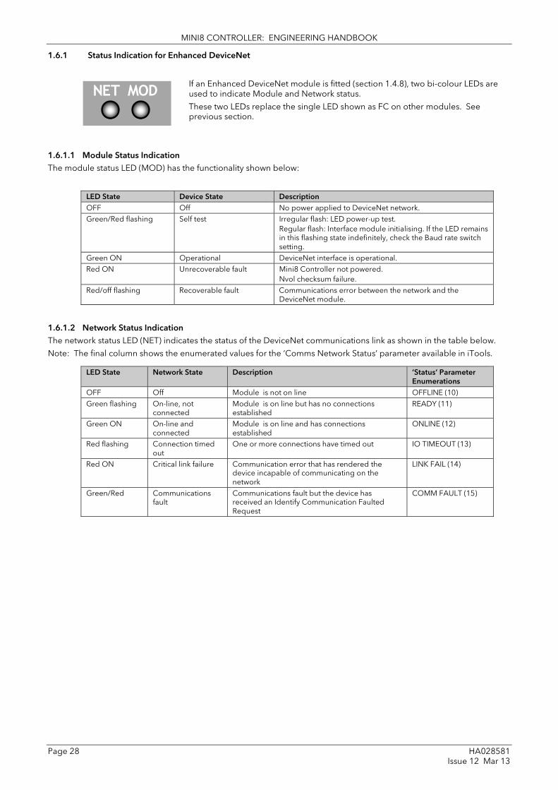
MINI8 CONTROLLER: ENGINEERING HANDBOOK
Page 28 HA028581 Issue 12 Mar 13
1.6.1 Status Indication for Enhanced DeviceNet
If an Enhanced DeviceNet module is fitted (section 1.4.8), two bi-colour LEDs are used to indicate Module and Network status.
These two LEDs replace the single LED shown as FC on other modules. See previous section.
1.6.1.1 Module Status Indication The module status LED (MOD) has the functionality shown below:
LED State Device State Description OFF Off No power applied to DeviceNet network. Green/Red flashing Self test Irregular flash: LED power-up test.
Regular flash: Interface module initialising. If the LED remains in this flashing state indefinitely, check the Baud rate switch setting.
Green ON Operational DeviceNet interface is operational. Red ON Unrecoverable fault Mini8 Controller not powered.
Nvol checksum failure. Red/off flashing Recoverable fault Communications error between the network and the
DeviceNet module.
1.6.1.2 Network Status Indication The network status LED (NET) indicates the status of the DeviceNet communications link as shown in the table below.
Note: The final column shows the enumerated values for the ‘Comms Network Status’ parameter available in iTools.
LED State Network State Description ‘Status’ Parameter Enumerations
OFF Off Module is not on line OFFLINE (10) Green flashing On-line, not
connected Module is on line but has no connections established
READY (11)
Green ON On-line and connected
Module is on line and has connections established
ONLINE (12)
Red flashing Connection timed out
One or more connections have timed out IO TIMEOUT (13)
Red ON Critical link failure Communication error that has rendered the device incapable of communicating on the network
LINK FAIL (14)
Green/Red Communications fault
Communications fault but the device has received an Identify Communication Faulted Request
COMM FAULT (15)
NET MOD

MINI8 CONTROLLER: ENGINEERING HANDBOOK
HA028581 Page 29 Issue 12 Mar 13
1.6.2 Status Indication for EtherNet/IP
If an EtherNet/IP module is fitted (section 1.4.11) two bi-colour LEDs are used to indicate Module and Network status.
These two LEDs replace the single LED shown as FC on other modules. See previous section.
1.6.2.1 Module Status Indication The module status LED (MOD) has the functionality shown below:
MOD LED State Description OFF Module has no power Flashing green Module is not configured Steady green Module is on line and operating correctly Flashing red Module has minor (1) recoverable fault Steady red Module has a major (2) non-recoverable fault Flashing green and red Module is performing power up testing
Note (1): MOD LED minor faults include the following:-
DHCP server is unavailable
Ethernet link is lost.
Invalid sub net mask.
Invalid IP Address.
Error on an Explicit message. E.g. bad parameter address, writing to a read only parameter.
Note (2): MOD LED major fault:-
Internal fault – return to your supplier for service
1.6.2.2 Network Status Indication The network status LED (NET) indicates the status of the EtherNet/IP communications link as shown in the table below.
Note: The final column shows the enumerated values for the ‘Comms Network Status’ parameter available in iTools.
NET LED State Mnemonic Description ‘Status’ Parameter Enumerations
OFF Off Module is not on line 20 OffLine Flashing Green No connections Module is on line but has no EtherNet/IP
connections established 21 NoConns
Steady Green Online Module is on line and has at least one EtherNet/IP connection established
22 OnLine
Flashing Red Connection timeout A connection has timed out 23 Timeout Steady Red Duplicate IP A duplicate IP address has been detected 24 DupIP Flashing Green/Red
Initialisation Module is initialising 25 Init
NET MOD

MINI8 CONTROLLER: ENGINEERING HANDBOOK
Page 30 HA028581 Issue 12 Mar 13
2. Chapter 2 Using the Mini8 controller The Mini8 controller does not have a display. The only means of configuring it, and of interfacing with it during normal operation is via digital communications.
The auxiliary communications port CC (RJ11) gives a Modbus interface, usually connected to iTools, for configuration and commissioning.
The main communications port, FC, offers Modbus, DeviceNet, CANopen, Profibus, EtherNet TCP or EtherNet/IP and is normally connected to the system of which the Mini8 controller is a part. It is the means by which the Mini8 controller is operated.
Below are ways the Mini8 controller may be used in a system. iTools is the best PC based solution. The Modbus single register addressing is best for Operator panels, PLCs where floating point may not be available or necessary. Some parameters may also be read this way as floats or long integers.
2.1 iTools iTools offers a pc based solution. The iTools suite allows configuration, commissioning, trend graphs and logging with OPC Scope, Program Editing, Recipes and User pages with View Builder.
2.1.1 iTools OPC Open server With an OPEN OPC server running on a PC all the Mini8 controller parameters are available to any third party package with an OPC client. The advantage of this is that all the parameters are addressed by name – the iTools OPC server handles all the physical communication addresses. An example would be with Wonderware inTouch using OPCLink. In this situation the user would not have to know any of the parameter addresses, and would just select a parameter by browsing through the namespace.
e.g. Eurotherm.ModbusServer.1.COM1.ID001-Mini8.Loop.1.Main.PV.
2.2 Modbus, single register, SCADA addressing The key parameters of the Mini8 controller are available at a fixed single 16 bit register address, independent of its configuration. These can be used with any device with a serial Modbus master. The parameters are listed in full with their addresses in Appendix A.
By default iTools displays the SCADA address of those parameters which are available.
As shown, not all the parameters within the instrument are available. If other parameters are required they can be obtained by using the Commstab folder. This allows up to 250 other parameters to be made available using indirection addressing. This is explained in Appendix A.
Also note that in this area the resolution (number of decimal points) has to be configured and the serial Master has to scale the parameter correctly.

MINI8 CONTROLLER: ENGINEERING HANDBOOK
HA028581 Page 31 Issue 12 Mar 13
2.3 Modbus (Floating Point) If the application requires the extra resolution, the Commstab folder also offers an alternative solution where a parameter can be indirectly addressed and communicated either as a floating point or as a double integer value – its ‘Native’ format. This can be used with any device e.g. PC or plc, with a serial Modbus master, able to decode a double register for floating point numbers and long integers. See Appendix A.
2.4 Fieldbus The Mini8 controller may be ordered with the option of DeviceNet, Profibus, CanOPEN or EtherNet/IP.
DeviceNet comes pre-configured with the key parameters of 8 PID loops and alarms (60 input parameters process variables, alarm status etc and 60 output parameters – setpoints etc.). Loops 9-16 are not included in the DeviceNet tables as there are insufficient attributes for the DeviceNet parameters. See Appendix B.
CANopen offers 4 receive & 4 Transmit PDOs and 1 server SDO with a 200 parameter pick list. See Appendix C
Profibus is set up using a GSD editor included on the iTools CD. The GSD editor sets up the instrument parameters that are required to be communicated with the master.
2.5 EtherNet (Modbus TCP) The Mini8 controller may be ordered with an EtherNet connection (10baseT) running ModbusTCP as the protocol. An instrument can therefore have a unique identity on the EtherNet network as well as a unique Modbus address for the Modbus master.
2.6 Mini8 Controller Execution The nominal update of all inputs and function blocks is 110ms. However, in complex applications the Mini8 controller will automatically extend this time in multiples of 110ms.
For example, eight simple heat/cool loops each with two alarms (40 wires) will run at 110ms, while the full EC8 configuration will run at 220ms because of the extra wiring and functionality.
The communications traffic will also have some effect on the update rate.
For example, an application using every function block and all 250 wires will run at 220ms with light communications traffic but may be slowed to 330ms with heavy traffic.
Note that as loading changes, the sample rate may increase or decrease automatically. In order to recover to a faster sample rate, the Mini8 controller must be running consistently with processing power to spare for at least 30s.

MINI8 CONTROLLER: ENGINEERING HANDBOOK
Page 32 HA028581 Issue 12 Mar 13
2.7 The iTools Operator Interface Much of this manual is about configuring the Mini8 controller with iTools. However iTools also provides an excellent commissioning tool and can be used as a long-term operator view if convenient.
First it is necessary to go ‘on-line’ to the Mini8 controller(s). This assumes the communication ports have been wired up to the COM port on the iTools computer (Chapter 10).
2.7.1 Scanning
Open iTools and, with the controller connected, press on the iTools menu bar. iTools will search the communications ports for recognisable instruments. Controllers connected using the RJ11 configuration port or with the configuration clip (CPI), may be found at address 255 (as a single point to point connection) or on a multidrop RS485 or RS422 network will be found at the address configured in the controller.
The iTools handbook, part no. HA028838, provides further step by step instructions on the general operation of iTools. This and the iTools software may be downloaded from www.eurotherm.co.uk.
When an instrument is found on the network it will be shown as, for example
‘COM1.ID001-Min8’ which represents <computer com port>.ID<instrument address>-<Instrument type>
Stop the scan once all the instruments have been found.
Once an instrument is found on the network a message ‘’sync pending’ or synchronizing’ is displayed next to it whilst iTools extracts the exact configuration from the instrument. Wait until this message disappears.
2.7.2 Browsing and Changing Parameter Values Once the instrument is synchronized the parameter navigation tree is displayed. The contents of this tree will vary depending on the actual configuration of the instrument.
The folders shown will be some of those which are always present –
e.g Instrument, IO, Comms, Access
as well as the configuration dependent ones-
e.g. Loops, Alarm, Lgc2 etc. which have been configured.

MINI8 CONTROLLER: ENGINEERING HANDBOOK
HA028581 Page 33 Issue 12 Mar 13
To view or change a parameter: 1. Highlight the folder
2. Press to get the parameter window or open up the parameter list by clicking on the required folder. Right click in the parameter list to reveal or hide columns.
3. To change the value of a parameter,
a. click the parameter value,
b. write in the new value. Note a pop-up window indicates the current value, and the high and low limits.
c. Hit <Enter> to enter the new value or <Escape> to cancel.
The ‘Access’ button puts the controller into configuration mode. In this mode the controller can be set up without its outputs being active. Press ‘Access’ again to return to operating level.
To find a parameter use the ‘Find’ tab at the bottom of the folder list.
☺ Tip: In parameter lists: Parameters in BLUE are read only
Parameters in BLACK are read/write.
☺ Tip: Every parameter in the parameter lists has a detailed description in the help file – just click on a parameter and hit Shift-F1 on the keyboard or right click and select parameter help.

MINI8 CONTROLLER: ENGINEERING HANDBOOK
Page 34 HA028581 Issue 12 Mar 13
2.8 Recipe Editor
Press for this feature. Up to 8 recipes can be stored. They can also be named by the user. Recipes allow the operator to change the operating values of up to 24 parameters in an instrument for different batch items/processes by simply selecting a particular recipe to load. Recipes are important for reducing error in setup and they remove the need for operator instructions fixed to the panel next to the instrument.
Note: Loading a recipe set causes the instrument to enter Standby mode momentarily during which time it does not control.
The Recipe Editor is used during configuration to assign the required parameters and to set up the values to be loaded for each recipe.
2.8.1 Recipe Menu Commands
Command Description Load Recipe Used to load a recipe file into the instrument Save Used to save the current recipe configuration into a file Edit Parameter Used to assign a parameter to a Tag. Parameters can also be assigned by 'drag and drop' from
the iTools parameter list Delete Parameter Used to delete an assigned parameter from the recipes Edit Parameter Value Used to edit the current value of the assigned parameter Rename Parameter Tag Allows the user to rename the Tag of the associated parameter. This tag is used on the instrument
to identify assigned parameters (default Value1 - Value24) Parameter Properties Used to find the properties and help information of the selected parameter Copy Parameter Used to copy the currently selected parameter Paste Parameter Used to assign a previously copied parameter to the selected Tag Columns Used to hide/show the Description and Comment Columns Load Access Level Used to configure the lowest access level in which the selected recipe is allowed to load Level1 Permitted to load when the instrument is in any of the access levels Config Permitted to load when the instrument is in the Config access level Never Never permitted to load Edit Data Set Value Used to edit the value of the selected assigned parameter within the selected recipe. Values can
also be edited via double left clicking the value itself Clear Data Set Value Used to clear the value of the selected assigned parameter within the selected recipe, thus
disabling it from loading when the recipe is selected to load Rename Data Set Allows the user to rename the selected recipe. This name is used to identify individual recipes
(default Set1 - Set8). Note: Number of recipes dependent upon features Clear Data Set Used to clear all values in the selected recipe, thus disabling all from loading when the recipe is
selected to load
Snapshot Values Used to copy all of the assigned parameters current values into the selected recipe
Copy Data Set Used to copy all values of the selected recipe Paste Data Set Used to paste all values of a previously copied recipe into the selected recipe

MINI8 CONTROLLER: ENGINEERING HANDBOOK
HA028581 Page 35 Issue 12 Mar 13
2.9 OPCScope OPC scope is a standalone OPC client that can be used to attach to the iTools OPCserver. It offers real time trend charts and data logging to disc in a .csv (comma separated variable) format which can easily be opened by a spreadsheet such as Excel.
With iTools open OPC Scope can be started using the icon .
But it can also be started on its own using the Windows Start/Programs/Eurotherm iTools/OPC Scope
Select Server/Connect or click the icon and the OPC server will start up (if it is not running) and will display the active ports on the computer. Opening the COM port will show the attached instruments as shown below.
The ‘ID001-Mini8’ folder will contain all the same folders for the instrument that would have been seen in iTools itself.
Expand the folder and double click on the blue item tag to add to the List Window. The List Window shows all the selected parameters and their current value.
Right click on a parameter to get the context menu.

MINI8 CONTROLLER: ENGINEERING HANDBOOK
Page 36 HA028581 Issue 12 Mar 13
2.9.1 OPC Scope List Window Context Menu
Command Description
Save Saves the OPC Scope configuration as <filename>.uix See Section 2.9.3
Copy Item DDE link Saves the DDE path to the clipboard.
‘Paste Special’ in an Excel cell and select ‘Paste Link’ and the current parameter value will be displayed in the cell.
Copy/Paste Item Copy & Paste
Add Item Add a new variable by name (easier to browse the navigation tree)
Remove Item Remove the selected item.
Write Value Write a new value (not if the item is Read Only).
Item appears on Chart
Up to 8 items can be trended on the Chart Window
Item Properties Gives the item properties as seen by OPC
The OPC List can contain parameters from any instrument attached to the Modbus network.
If you have iTools Open (not iTools Standard) then OPC Scope can run on a remote networked computer. Enter the name of the server computer (attached to the instruments) the ‘Computer’ window and browse for the ‘Eurotherm.ModbusServer1’.
2.9.2 OPC Scope Chart Window
Click the Chart tab at the bottom of the display window and select Chart Control Panel.
1. Items. Includes all the items in the list window. Those items ticked (up to 8) will appear on the chart.
2. Axes. Allows time intervals from 1 minute to 1 month. Vertical axes can be ‘auto’ scaled or a fixed range may be entered.
3. General. Allows selection of colours, grid, legends and a data box.
4. Plot. Allows selection of line thickness and printing
5. Review. Allows review of early history charts.
These are also available on the toolbar.

MINI8 CONTROLLER: ENGINEERING HANDBOOK
HA028581 Page 37 Issue 12 Mar 13
iTools Trend Graph showing Loop1 SP and PV
The icon allows the chart to occupy all the window space.

MINI8 CONTROLLER: ENGINEERING HANDBOOK
Page 38 HA028581 Issue 12 Mar 13
2.9.3 OPC Server iTools and OPC Scope all use the Eurotherm OPC Server to provide the connection between the instruments and the computer displays. When you ‘scan’ for instruments on iTools it is in fact the OPC Server that is actually doing the work in background (the window is not usually displayed).
OPC Scope can run on its own but for it to find the instruments on the network it is necessary to tell the server where they are.
1. Start OPC Server (Windows Start/Programs/Eurotherm iTools/OPC Server)
2. On the menu go to ‘Network’ and select ‘Start One-Shot Scan’
3. Stop the scan when all the instruments have been found.
4. On the menu go to ‘File’ and select ‘Save As’ and save the file with a suitable name.
5. Once saved you will be asked ‘Would you like to make this file the default start server address file?’ – select ‘Yes’.
6. Close the server.
Now if you double click on an OPC Scope file e.g. Mini8 Project.uix then this file will open OPC Scope and in turn, in background, OPC scope will open the OPC Server with this instrument file loaded. OPC Scope will then be active with live data from the instrument(s).

MINI8 CONTROLLER: ENGINEERING HANDBOOK
HA028581 Page 39 Issue 12 Mar 13
3. Chapter 3 Configuration Using ITools
WARNING
Configuration level gives access to a wide range of parameters that match the controller to the process. Incorrect configuration could result in damage to the process being controlled and/or personal injury. It is the responsibility of the person commissioning the process to ensure that the configuration is correct.
In configuration level the controller may not be controlling the process or providing alarm indication. Do not select configuration level on a live process.
3.1 Configuration The Mini8 controller is supplied unconfigured, unless ordered preconfigured, e.g. EC8. An unconfigured Mini8 controller has to be configured for use in an application. This is performed using iTools.
The iTools handbook, part no. HA028838 provides further step by step instructions on the general operation of iTools. This and the iTools software may be downloaded from www.eurotherm.co.uk.
3.1.1 On-Line/Off-line Configuration
If iTools is connected to a real Mini8 controller then all the parameter changes made will be written to the device immediately. Once the Mini8 controller is configured and working as required, its final configuration can be saved to disk as a ‘clone’ file of the format <name>.uic.
Alternatively iTools can be used ‘off-line’ without a real Mini8 controller connected at all. This virtual Mini8 controller can be created in iTools and again saved to disk as a clone file. This file can later be loaded into a real Mini8 controller to create the required real application. See Section 3.3.
3.2 Connecting a PC to the Mini8 Controller 3.2.1 Configuration Cable and Clip
The controller may be connected to the PC running iTools using the Eurotherm cable SubMin8/Cable/Config from the RJ11 port connecting to a serial port on the PC.
Alternatively a Configuration Clip is available from Eurotherm that can be fitted into the rear of the controller.
The benefit of using this arrangement is that it is not necessary to power the controller, since the clip provides the power to the internal memory of the controller.
3.2.2 Scanning
Open iTools and, with the controller connected, press on the iTools menu bar. iTools will search the communications ports and TCP/IP connections for recognisable instruments. Controllers connected using the RJ11 configuration port or with the configuration clip (CPI), will be found at address 255 regardless of the address configured in the controller. These connections only work from iTools to a single controller.
The iTools handbook, part no. HA028838, provides further step by step instructions on the general operation of iTools. This and the iTools software may be downloaded from www.eurotherm.co.uk.
In the following pages it is assumed that the user is familiar with iTools and has a general understanding of Windows.

MINI8 CONTROLLER: ENGINEERING HANDBOOK
Page 40 HA028581 Issue 12 Mar 13
3.3 Cloning Saving a Clone File
On the iTools menu ‘File – Save to File’ allows the clone file of the attached Mini8 controller to be saved to disc as <user name>.UIC file. This can be loaded into another Mini8 controller.
Note that after synchronization iTools using uses a ‘quick’ save and will only resave parameters that have been changed through iTools itself. If there is any chance that parameters have been changed through the other port then it is necessary to resave all the parameters. On the menu bar under Options – Cloning ensure Reload is selected. The safest option is to keep Ask selected.
Loading a clone file On the iTools menu ‘File – Load values File’ allows a clone file of the form <user name>.UIC to be loaded into an attached Mini8 controller unit. Whilst loading, the report window will indicate what is happening. It makes a number of attempts to load all the values and may report some errors. This is generally not an issue. If for some reason the load fails iTools will report specifically that the load ‘Failed’
Communications port parameters A Mini8 controller clone file contains information on both the CC and FC port config settings. Depending on which comms port is used to load a clone file cloning will behave in a different manner.
Loading the clone file through the FC port will cause the CC port settings to be updated
Loading the clone file through the CC port will cause the FC port settings to be updated

MINI8 CONTROLLER: ENGINEERING HANDBOOK
HA028581 Page 41 Issue 12 Mar 13
3.4 Configuring the Mini8 Controller
Once iTools is successfully connected to a Mini8 controller, it can be configured for the application in hand. Configuration involves selection of the required elements of functionality called ‘function blocks’ and setting their parameters to the correct values. The next stage is to connect all the function blocks together to create the required strategy of control for the application.
3.4.1 Function Blocks The controller software is constructed from a number of ‘function blocks’. A function block is a software device that performs a particular duty within the controller. It may be represented as a ‘box’ that takes data in at one side (as inputs), manipulates the data internally (using internal parameter values) and ‘outputs’ the results. Some of these internal parameters are available to the user so that they can be adjusted to suit the characteristics of the process that is to be controlled.
A representation of a function block is shown below.
Internal Parameters
Figure 3-1: Example of a Function Block
In the controller, parameters are organised in simple lists. The top of the list shows the list header. This corresponds to the name of the function block and is generally presented in alphabetical order. This name describes the generic function of the parameters within the list. For example, the list header ‘AnAlm’ contains parameters that enable you to set up analogue alarm conditions.
Input Parameters
Output Parameters
Name – corresponds to Folder

MINI8 CONTROLLER: ENGINEERING HANDBOOK
Page 42 HA028581 Issue 12 Mar 13
3.4.2 Soft Wiring Soft Wiring (sometimes known as User Wiring) refers to the connections that are made in software between function blocks. Soft wiring, which will generally be referred to as ‘Wiring’ from now on is created during the instrument configuration using the iTools configuration package.
In general every function block has at least one input and one output. Input parameters are used to specify where a function block reads its incoming data (the ‘Input Source’). The input source is usually wired from the output of a preceding function block. Output parameters are usually wired to the input source of subsequent function blocks.
All parameters shown in the function block diagrams are also shown in the parameter tables, in the relevant chapters, in the order in which they appear in iTools.
Figure 3.2 shows an example of how the thermocouple is wired to the PID Loop input and the PID Loop channel 1 (heat) output is wired to the time proportioning logic output.
Figure 3-2: Function Block Wiring
t/c to PID input PID output to logic output

MINI8 CONTROLLER: ENGINEERING HANDBOOK
HA028581 Page 43 Issue 12 Mar 13
3.5 Simple Worked Example Using function blocks and wiring the following sections will show a blank Mini8 controller being configured to have one PID loop.
3.5.1 The I/O
With the Mini8 controller successfully connected to iTools configuration can begin.
☺ Tip: In parameter lists:
Parameters in BLUE are read only
Parameters in BLACK are read/write.
☺ Tip: Every parameter in the parameter lists has a detailed description in the help file – just click on a parameter and hit Shift-F1 on the keyboard or right click and select parameter help.
The I/O will already have been installed in the Mini8 controller and can be checked in iTools.
Example 1: Thermocouple Input Configuration
In the IO list ModIDs select the type of module. Thermocouple modules may be 4 input modules or 8 input modules.
Figure 3-3: Mini8 controller I/O Modules
This unit has an 8 thermocouple input board in slot 1, a CT3 input card in slot 2, and 2 DO8 output cards in slot 3 and slot 4. Clicking on the ‘Mod’ tab will enable the first channel of the thermocouple card to be configured. Firstly the Mini8 controller has to be put into configuration mode. Go to Device/Access/Configuration or click on the Access button:

MINI8 CONTROLLER: ENGINEERING HANDBOOK
Page 44 HA028581 Issue 12 Mar 13
Figure 3-4: Thermocouple Input
Select the I/O type, linearisation, units, resolution etc. required. Parameter details are in Section 7.5.
The other thermocouple channels can be found by using the 2, 3, 4…7, 8 tabs on the top of the parameter window.
Slot 2 in the Mini8 controller has a CT3 input card and this is configured elsewhere so the Tabs 9 to 16 are not shown.
Slot 3 has a DO8 output card and the first channel of this will be on tab 17 (to 24)
Slot 4 has a DO8 output card and the first channel of this will be on tab 25 (to 32)
Figure 3-5: Digital Output Channel
Set this channel up as required, IOType, MinOnTime etc. as required. The parameters are detailed in Section 7.3. The remaining channels on this slot will be found under the tabs 18 to 24. Slot 4 also contains a DO8 output card with outputs under tabs 25 to 32. The fixed I/O is always there and there is nothing that has to be configured. The Current Monitor is covered in Chapter 7.9.

MINI8 CONTROLLER: ENGINEERING HANDBOOK
HA028581 Page 45 Issue 12 Mar 13
Example 2: RTD Input Configuration
In the IO list ModIDs select the type of module. RTD modules are 4 input modules [RT4Mod (173)].
Figure 3-6: Mini8 Controller IO Module1 Defined as RTD
RTDs can be defined as 2-wire [RTD2 (32)], 3-wire [RTD3 (33)] or 4-wire [RTD4 (34)] in the module definition list. It is important that the ‘IO Type’ is configured to match the RTD in use so that the correct lead compensation calculation is selected.
Figure 3-7: Module 1 defined as RTD4

MINI8 CONTROLLER: ENGINEERING HANDBOOK
Page 46 HA028581 Issue 12 Mar 13
3.5.2 Wiring
The IO that has been configured now needs to be wired to PID loops and other function blocks.
Select (GWE) to create and edit instrument wiring.
Figure 3-8: List of Function Blocks & Graphical Wiring Window
The left window now contains a list of the function blocks available.
The Graphical Wiring Editor window
To add a function block drag it from the list and drop it on this editor.
To add IO first expand the IO block (click the + ) and then expand the Mod to show the IO channels 1 to 32
Similarly to add a loop first expand the loop block (click the +) to show loops 1 to 8

MINI8 CONTROLLER: ENGINEERING HANDBOOK
HA028581 Page 47 Issue 12 Mar 13
Use drag and drop to select the first thermocouple from IOMod 1, the Cool output from IOMod 17 and the Heat output from IOMod 25 and drop them on the wiring window.
Finally take the first PID block from Loop/Loop 1 and drop it on the wiring window. Note that as each block is used it greys out on the list.
There should now be 4 blocks on the window. Those blocks are shown with dotted lines, as they have not been loaded into the Mini8 controller.
First make the following wire connections.
1. Click on IO.Mod1.PV and move the pointer to Loop 1.MainPV and click again. A dotted wire will have connected the two together.
2. Similarly join Loop1.OP.Ch1Out to IOMod 25.PV (heat output)
3. Enable the Cool output by clicking the select arrow to the top of the loop block:
4. Loop1.OP.Ch2Out to IOMod 17.PV (cool output)
Figure 3-9: Wired Blocks before download
click here
and select PID output

MINI8 CONTROLLER: ENGINEERING HANDBOOK
Page 48 HA028581 Issue 12 Mar 13
5. Right click on the Loop 1 function Block and select ‘Function Block View’. This opens the Loop parameter list on top of the wiring editor.
Figure 3-10: PID Function Block
This enables the PID function block to be set up to suit the required application. See Chapter 17 for details.
6. Click on the instrument button to download the application:
7. Once downloaded the dotted lines around the function blocks and the wires will become solid to show that the application is now in the Mini8 controller. The upper status line also shows that 3 wires have been used out of those available. Max is 250 but quantity depends on number of wires ordered (30, 60, 120 or 250).
8. Put the Mini8 controller back into Operating mode by clicking the Access button:
9. The Mini8 controller will now control the Loop1 as configured.

MINI8 CONTROLLER: ENGINEERING HANDBOOK
HA028581 Page 49 Issue 12 Mar 13
3.6 Graphical Wiring Editor
Select (GWE) to view and edit instrument wiring. You can also add comments and monitor parameter values.
1. Drag and drop required function blocks into the graphical wiring from the list in the left pane 2. Click on parameter to be wired from and drag the wire to the parameter to be wired to (do not hold mouse
button down) 3. Right click to edit parameter values 4. Select parameter lists and switch between parameter and wiring editors 5. Download to instrument when wiring completed 6. Add comments and notes 7. Dotted lines around a function block show that the application requires downloading
Add comment and notes
Right click to edit parameter values
Click this button to wire unshown parameters
Indicates execution order
Blocks ‘clear’ when used

MINI8 CONTROLLER: ENGINEERING HANDBOOK
Page 50 HA028581 Issue 12 Mar 13
3.6.1 Graphical Wiring Toolbar
3.6.2 Function Block A Function Block is an algorithm that may be wired to and from other function blocks to make a control strategy. The Graphical Wiring Editor groups the instrument parameters into function blocks. Examples are: a control loop and a mathematical calculation.
Each function block has inputs and outputs. Any parameter may be wired from, but only parameters that are alterable may we wired to.
A function block includes any parameters that are needed to configure or operate the algorithm.
3.6.3 Wire A wire transfers a value from one parameter to another. They are executed by the instrument once per control cycle.
Wires are made from an output of a function block to an input of a function block. It is possible to create a wiring loop, in this case there will be a single execution cycle delay at some point in the loop. This point is shown on the diagram by a || symbol and it is possible to choose where that delay will occur.
3.6.4 Block Execution Order The order in which the blocks are executed by the instrument depends on the way in which they are wired.
The order is automatically worked out so that the blocks execute on the most recent data.
3.6.5 Using Function Blocks If a function block is not faded in the tree then it can be dragged onto the diagram. The block can be dragged around the diagram using the mouse.
A labelled loop block is shown here. The label at the top is the name of the block.
When the block type information is alterable, click on the box with the arrow in it on the right to edit that value.
The inputs and outputs that are considered to be of most use are always shown. In most cases all of these will need to be wired up for the block to perform a useful task. There are exceptions to this and the loop is one of those exceptions.
If you wish to wire from a parameter, which is not shown as a recommended output click on the icon in the bottom right, and a full list of parameters in the block will be shown, click on one of these to start a wire.
To start a wire from a recommended output just click on it.
Click the icon in the bottom right hand corner to wire other function block parameters not shown on the list on the right hand side.
Delete, Undo & Redo
Grid on/off
Pan Drawing
Zoom Drawing
Grab & Pan
Select
Download
IO Setup Paste Create a Compound
Copy a Diagram Fragment to a File
Paste a Diagram Fragment to a FileCut Copy

MINI8 CONTROLLER: ENGINEERING HANDBOOK
HA028581 Page 51 Issue 12 Mar 13
3.6.5.1 Function Block Context Menu Right clicking displays the context menu with the following entries.
Function Block View Brings up an iTools parameter list which shows all the parameters in the function block. If the block has sub-lists these are shown in tabs
Re-Route Wires Throw away current wire route and do an auto-route of all wires connected to this block
Re-Route Input Wires Only do a re-route on the input wires
Re-Route Output Wires
Only do a re-route on the output wires
Show wires using tags Shows the beginning and end of each wire with a descriptor showing the source or destination. Used to simplify a diagram with many wires.
Hide Unwired Connections
Hides function block pins that are not used.
Cut Cut the selected function block
Copy Right click over an input or output and copy will be enabled, this menu item will copy the iTools "url" of the parameter which can then be pasted into a watch window or OPC Scope
Paste Add a new copy of the function block
Delete If the block is downloaded mark it for delete, otherwise delete it immediately
Undelete This menu entry is enabled if the block is marked for delete and unmarks it and any wires connected to it for delete
Bring To Front Bring the block to the front of the diagram. Moving a block will also bring it to the front
Push To Back Push the block to the back of the diagram. Useful of there is something underneath it
Edit Parameter Value This menu entry is enabled when the mouse is over an input or output parameter. When selected it creates a parameter edit dialog so the value of that parameter can be changed
Parameter Properties Selecting this entry brings up the parameter properties window. The parameter properties window is updated as the mouse is moved over the parameters shown on the function block
Parameter Help Selecting this entry brings up the help window. The help window is updated as the mouse is moved over the parameters shown on the function block. When the mouse is not over a parameter name the help for the block is shown
3.6.6 Tooltips Hovering over different parts of the block will bring up tooltips describing the part of the block beneath the mouse.
If you hover over the parameter values in the block type information a tooltip showing the parameter description, its OPC name, and, if downloaded, its value will be shown.
A similar tool-tip will be shown when hovering over inputs and outputs.

MINI8 CONTROLLER: ENGINEERING HANDBOOK
Page 52 HA028581 Issue 12 Mar 13
3.6.7 Function Block State The blocks are enabled by dragging the block onto the diagram, wiring it up, and downloading it to the instrument
When the block is initially dropped onto the diagram it is drawn with dashed lines.
When in this state the parameter list for the block is enabled but the block itself is not executed by the instrument.
Once the download button is pressed the block is added to the instrument function block execution list and it is drawn with solid lines.
If a block which has been downloaded is deleted, it is shown on the diagram in a ghosted form until the download button is pressed.
This is because it and any wires to/from it are still being executed in the instrument. On download it will be removed from the instrument execution list and the diagram. A ghosted block can be undeleted using the context menu.
When a dashed block is deleted it is removed immediately.

MINI8 CONTROLLER: ENGINEERING HANDBOOK
HA028581 Page 53 Issue 12 Mar 13
3.6.8 Using Wires
3.6.8.1 Making A Wire Between Two Blocks
• Drag two blocks onto the diagram from the function block tree.
• Start a wire by either clicking on a recommended output or clicking on the icon at the bottom right corner of the block to bring up the connection dialog. The connection dialog shows all the connectable parameters for the block, if the block has sub-lists the parameters are shown in a tree. If you wish to wire a parameter which is not currently available click the red button at the bottom of the connection dialog. Recommended connections are shown with a green plug, other parameters which are available are yellow and if you click the red button the unavailable parameters are shown red. To dismiss the connection dialog either press the escape key on the keyboard or click the cross at the bottom left of the dialog.
• Once the wire has started the cursor will change and a dotted wire will be drawn from the output to the current mouse position.
• To make the wire either click on a recommended input to make a wire to that parameter or click anywhere except on a recommended input to bring up the connection dialog. Choose from the connection dialog as described above.
• The wire will now be auto-routed between the blocks.
New wires are shown dotted until they are downloaded
3.6.8.2 Wire Context Menu
The wire block context menu has the following entries on it.
Force Exec Break
If wires form a loop a break point has to be found where the value which is written to the block input comes from a block which was last executed during the previous instrument execute cycle thus introducing a delay. This option tells the instrument that if it needs to make a break it should be on this wire
Re-Route Wire Throw away wire route and generate an automatic route from scratch
Use Tags If a wire is between blocks which are a long way apart, then, rather than drawing the wire, the name of the wired to/from parameter can be shown in a tag next to the block. Draw the wire first then use this menu to toggle this wire between drawing the whole wire and drawing it as tags
Find Start Find the source of the selected wire
Find End Find the destination of the selected wire
Delete If the wire is downloaded mark it for delete, otherwise delete it immediately
Undelete This menu entry is enabled if the wire is marked for delete and unmarks it for delete
Bring To Front Bring the wire to the front of the diagram. Moving a wire will also bring it to the front
Push To Back Push the wire to the back of the diagram

MINI8 CONTROLLER: ENGINEERING HANDBOOK
Page 54 HA028581 Issue 12 Mar 13
3.6.8.3 Wire Colours Wires can be the following colours:
Black Normal functioning wire.
Red The wire is connected to an input which is not alterable when the instrument is in operator mode and so values which travel along that wire will be rejected by the receiving block
Blue The mouse is hovering over the wire, or the block to which it is connected it selected. Useful for tracing densely packed wires
Purple The mouse is hovering over a 'red' wire
3.6.8.4 Routing Wires When a wire is placed it is auto-routed. The auto routing algorithm searches for a clear path between the two blocks. A wire can be auto-routed again using the context menus or by double clicking the wire.
If you click on a wire segment you can drag it to manually route it. Once you have done this it is marked as a manually routed wire and will retain it's current shape. If you move the block to which it is connected the end of the wire will be moved but as much of the path as possible of the wire will be preserved.
If you select a wire by clicking on it, it will be drawn with small boxes on it's corners.
3.6.8.5 Tooltips Hover the mouse over a wire and a tooltip showing the names of the parameters which are wired and, if downloaded, their current values will also be shown.
3.6.9 Using Comments Drag a comment onto the diagram and the comment edit dialog will appear.
Type in a comment. Use new lines to control the width of the comment, it is shown on the diagram as typed into the dialog. Click OK and the comment text will appear on the diagram. There are no restrictions on the size of a comment. Comments are saved to the instrument along with the diagram layout information.
Comments can be linked to function blocks and wires. Hover the mouse over the bottom right of the comment and a chain icon will appear, click on that icon and then on a block or a wire. A dotted wire will be drawn to the top of the block or the selected wire segment.
3.6.9.1 Comment Context Menu The comment context menu has the following entries on it.
Edit Open the comment edit dialog to edit this comment
Unlink If the comment is linked to a block or wire this will unlink it
Cut Remove the comment
Copy To make a copy of the comment
Paste To Paste a new copy of the comment
Delete If the comment is downloaded mark it for delete, otherwise delete it immediately
Undelete This menu entry is enabled if the comment is marked for delete and unmarks it for delete
Bring To Front
Bring the comment to the front of the diagram. Moving a comment will also bring it to the front
Push To Back
Push the comment to the back of the diagram. Useful if there is something underneath it

MINI8 CONTROLLER: ENGINEERING HANDBOOK
HA028581 Page 55 Issue 12 Mar 13
3.6.10 Using Monitors Drag a monitor onto the diagram and connect it to a block input or output or a wire as described in ‘Using Comments’.
The current value (updated at the iTools parameter list update rate) will be shown in the monitor. By default the name of the parameter is shown, double click or use the context menu to not show the parameter name.
3.6.10.1 Monitor Context Menu The monitor context menu has the following entries on it.
Show Names
Show parameter names as well as values
Unlink If the monitor is linked to a block or wire this will unlink it
Cut Remove the monitor
Copy Make a copy of the monitor
Paste Paste the copy of the monitor
Delete If the monitor is downloaded mark it for delete, otherwise delete it immediately
Undelete This menu entry is enabled if the monitor is marked for delete and unmarks it for delete
Bring To Front
Bring the monitor to the front of the diagram. Moving a monitor will also bring it to the front
Push To Back
Push the monitor to the back of the diagram. Useful if there is something underneath it
3.6.11 Downloading The wires have to be downloaded to the instrument together. When the wiring editor is opened the current wiring and diagram layout is read from the instrument. No changes are made to the instrument function block execution or wiring until the download button is pressed.
When a block is dropped on the diagram instrument parameters are changed to make the parameters for that block available. If you make changes and close the editor without saving them there will be a delay while the editor clears these parameters.
When you download, the wiring is written to the instrument that then calculates the block execution order and starts executing the blocks. The diagram layout including comments and monitors is then written into instrument flash memory along with the current editor settings. When you reopen the editor the diagram will be shown positioned the same as when you last downloaded.
3.6.12 Selections Wires are shown with small blocks at their corners when selected. All other items have a dotted line drawn round them when they are selected.
3.6.12.1 Selecting Individual Items Clicking on an item on the drawing will select it.
3.6.12.2 Multiple Selection Control click an unselected item to add it to the selection, doing the same on a selected item unselects it.
Alternatively, hold the mouse down on the background and wipe it to create a rubber band, anything which isn't a wire inside the rubber band will be selected.
Selecting two function blocks also selects any wires which join them. This means that if you select more than one function block using the rubber band method any wires between them will also be selected.
Pressing Ctrl-A selects all blocks and wires.

MINI8 CONTROLLER: ENGINEERING HANDBOOK
Page 56 HA028581 Issue 12 Mar 13
3.6.13 Colours Items on the diagram are coloured as follows:
Red Function blocks, comments and monitors which partially obscure or are partially obscured by other items are drawn red. If a large function block like the loop is covering a small one like a math2 the loop will be drawn red to show that it is covering another function block. Wires are drawn red when they are connected to an input which is currently unalterable. Parameters in function blocks are coloured red if they are unalterable and the mouse pointer is over them
Blue Function blocks, comments and monitors which are not coloured red are coloured blue when the mouse pointer is over them. Wires are coloured blue when a block to which the wire is connected is selected or the mouse pointer is over it. Parameters in function blocks are coloured blue if they are alterable and the mouse pointer is over them
Purple A wire which is connected to an input which is currently unalterable and a block to which the wire is connected is selected or the mouse pointer is over it is coloured purple (red + blue)
3.6.14 Diagram Context Menu Highlight an area of the graphical wiring by left clicking the mouse button and dragging around the required area. Right click in the area to show the Diagram Context Menu. The diagram context menu has the following entries:-
Cut To delete the selected area
Copy To make a copy of the selected area
Paste To paste the selected area
Re-Route Wires Throw away current wire route and do an auto-route of all selected wires. If no wires are selected this is done to all wires on the diagram
Align Tops Line up the tops of all the selected items except wires
Align Lefts Line up the left hand side of all the selected items except wires
Space Evenly This will space the selected items such that their top left corners are evenly spaced. Select the first item, then select the rest by control-clicking them in the order you wish them to be spaced, then choose this menu entry
Delete Marks all selected items for deletion (will be deleted on next download).
Undelete This menu entry is enabled if any of the selected items are marked for deletion and unmarks them when selected
Select All To select the complete graphical wiring
Create Compound Create a new tab (Compund 1, 2, etc) of the selected area
Rename To customise the Compound name.
Copy Graphic If there is a selection it is copied to the clipboard as a Windows metafile, if there is no selection the whole diagram is copied to the clipboard as a Windows metafile. Paste into your favourite documentation tool to document your application. Some programs render metafiles better than others, the diagram may look messy on screen but it should print well
Save Graphic Same as Copy Graphic but saves to a metafile rather than putting it on the clipboard
Copy Fragment to File
To make a copy of the selected area and save it to file
Paste Fragment from File
To paste the selected area from file
Center To place the selected area in the centre of the graphical wiring view.

MINI8 CONTROLLER: ENGINEERING HANDBOOK
HA028581 Page 57 Issue 12 Mar 13
3.6.15 Wiring Floats with Status Information There is a subset of float values which may be derived from an input which may become faulty for some reason, e.g. sensor break, over-range, etc. These values have been provided with an associated status which is automatically inherited through the wiring. The list of parameters which have associated status is as follows:-
Block Input Parameters Output Parameters Loop.Main PV PV Loop.SP TrackPV Math2 In1 Out
In2 Programmer.Setup PVIn Poly In Out Load PVOut1
PVOut2 Lin16 In Out Txdr InVal OutVal IPMonitor In Out SwitchOver In1
In2 Total In Mux8 In1 to 8 Out Multi-oper In1 to 8 SumOut, MaxOut, MinOut, AverageOut Lgc2 In1
In2 UsrVal Val Val Humidity WetTemp RelHumid
DryTemp DewPoint PsychroConst Pressure
IO.MOD 1.PV to 32.PV 1.PV to 32.PV
Parameters appear in both lists where they can be used as inputs or outputs depending on configuration. The action of the block on detection of a ‘Bad’ input is dependent upon the block. For example, the loop treats a ‘Bad’ input as a sensor break and takes appropriate action; the Mux8 simply passes on the status from the selected input to the output, etc.
The Poly, Lin16, SwitchOver, Multi-Operator, Mux8, IO.Mod.n.PV blocks can be configured to act on bad status in varying ways. The options available are as follows:-
0: Clip Bad
The measurement is clipped to the limit it has exceeded and its status is set to ‘BAD’, so that any function block using this measurement can operate its own fallback strategy. For example, a control output may be held at its current value.
1: Clip Good
The measurement is clipped to the limit it has exceeded and its status is set to ‘GOOD’, such that any function block using this measurement may continue to calculate and not employ its own fallback strategy.
2: Fallback Bad
The measurement will adopt the configured fallback value that has been set by the user. In addition the status of the measured value will be set to ‘BAD’, such that any function block using this measurement can operate its own fallback strategy. For example, control loop may hold its output to the current value.
3: Fallback Good
The measurement will adopt the configured fallback value that has been set by the user. In addition the status of the measured value will be set to ‘GOOD’, such that any function block using this measurement may continue to calculate and not employ its own fallback strategy
4: Up Scale
The measurement will be forced to adopt its high limit. This is like having a resistive pull up on an input circuit. In addition the status of the measured value will be set to ‘BAD’, such that any function block using this measurement can operate its own fallback strategy. For example, the control loop may hold its output to the current value.
5: Down Scale
The measurement will be forced to adopt its low limit. This is like having a resistive pull down on an input circuit. In addition the status of the measured value will be set to ‘BAD’, such that any function block using this measurement can operate its own fallback strategy. For example, the control loop may hold its output to the current value.

MINI8 CONTROLLER: ENGINEERING HANDBOOK
Page 58 HA028581 Issue 12 Mar 13
3.6.16 Edge Wires If the Loop.Main.AutoMan parameter were wired from a logic input in the conventional manner it would be impossible to put the instrument into manual via communications. Other parameters need to be controlled by wiring but also need to be able to change under other circumstances, e.g. Alarm Acknowledgements. for this reason some Boolean parameters are wired in an alternative way.
These are listed as follows:-
SET DOMINANT When the wired in value is 1 the parameter is always updated. This will have the effect of overriding any changes through digital communications. When the wired in value changes to 0 the parameter is initially changed to 0 but is not continuously updated. This permits the value to be changed through digital communications.
Loop.Main.AutoMan Programmer.Setup.ProgHold Access.StandBy
RISING EDGE
When the wired in value changes from 0 to 1, a 1 is written to the parameter. At all other times the wire does not update the parameter. This type of wiring is used for parameters that start an action and when once completed the block clears the parameter. When wired to, these parameters can still be operated via digital communications.
Loop.Tune.AutotuneEnable Txdr.ClearCal Alarm.Ack Txdr.StartCal DigAlarm.Ack Programmer.Setup.ProgRun Txdr.StartHighCal AlmSummary.GlobalAck Programmer.Setup.AdvSeg Txdr.StartTare Programmer.Setup.SkipSeg Instrument.Diagnostics.
ClearStats IPMonitor.Reset
BOTH EDGE This type of edge is used for parameters which may need to be controlled by wiring or but should also be able to be controlled through digital communications. If the wired in value changes then the new value is written to the parameter by the wire. At all other times the parameter is free to be edited through digital communications.
Loop.SP.RateDisable Loop.OP.RateDisable

MINI8 CONTROLLER: ENGINEERING HANDBOOK
HA028581 Page 59 Issue 12 Mar 13
4. Chapter 4 Mini8 controller Overview Input and output parameters of function blocks are wired together using software wiring to form a particular control strategy within the Mini8 controller. An overview of all the available functions and where to get more detail is shown below.
Figure 4-1: Controller Example
Mini8 controllers are supplied unconfigured, and with those blocks included in the order code. Option EC8 is supplied with function blocks pre-wired to give an 8 loop heat/cool controller suitable for Extrusion. See data sheet HA028519.
The purpose of the PID control blocks is to reduce the difference between SP and PV (the error signal) to zero by providing a compensating output to the plant via the output driver blocks.
The timer, programmer and alarms blocks may be made to operate on a number of parameters within the controller, and digital communications provides an interface to data collection and control.
The controller can be customised to suit a particular process by ‘soft wiring’ between function blocks.
Loops 1 to 16 Loop Folder
Chapter 17
Thermocouples
Outputs
FixedIO / IO
Logic Input Chap. 7.8, 7.2
Setpoint Loop/SP folder Folder Chapter 17.6
Mod.25 to Mod.32
Analogue OP Chapter 7.7
To plant devices
Mod.1 to Mod.32
T/C, RTD, mA, mV Chapter 7.5, 7.6
Mod.1 to Mod.32
Logic Output Chapter 7.3
Alarm(s) Alarm Folder
Chapter 8
Timer/Clock/ Counter/Totaliser
Chapter 11
Field Comms Comms/FC
Folder Chapter 10
PC, plc
Inputs Control Processes
FixedIO /IO Relay O/P
Chap. 7.8, 7.4
Digital AlarmsDig Alm Folder
Chapter 8.3
Application specific Humidity Zirconia
Chapter 12
Programmer Prog Folder
Chapter 18
BCD Input BCD In Folder
Chapter 9
Input Linearisation
Lin 16 Folder Chapter 15
Maths Math2 & Mux8
Folder Chapter 14
Polynomial Poly Folder Chapter 15
Switchover SwOver Folder
Chapter 19
Transducer Scaling Txdr Folder
Chapter 20
User Values UsrVal Folder
Chapter 21
Maths Lgc2 & Lgc8
Folder Chapter 14
Current I/p IO.Current Monitor
Folder Chapter 7.9
Alarm Summary Alarm Summary
Folder Chapter 8.7
Dig Inputs
Current Transformers

MINI8 CONTROLLER: ENGINEERING HANDBOOK
Page 60 HA028581 Issue 12 Mar 13
4.1 Complete list of Function Blocks.
The list opposite represents an unconfigured Mini8 that has been ordered with all features enabled.
If a particular block or blocks do not appear in your instrument then the option has not been ordered. Check the order code of your instrument and contact Eurotherm.
Examples of features that may not have been enabled are:
Loops
Programmer
Recipe
Humidity
Once a block is dragged and dropped onto the graphical wiring window, the block icon in the block list opposite will be greyed out. At the same time a folder containing the blocks parameters will have been created in the Browse List.

MINI8 CONTROLLER: ENGINEERING HANDBOOK
HA028581 Page 61 Issue 12 Mar 13
5. Chapter 5 Access Folder
Folder: Access Sub-folder: none
Name
Parameter Description
Value
Default Access Level
ClearMemory Cold start the instrument
No Disabled No Conf
App Mini8 controller memory reset but comms and linearisation tables retained
LinTables Custom Linearisation tables are deleted
InitComms Comms ports reset to default configurations
Wires Clear all wiring
AllMemory
All instrument memory is set to default values
Programs
All Programs cleared
CustomerID Customer Identifier
Reference number for customer use 0 Oper
Standby Set Instrument to standby
No / Yes No Oper

MINI8 CONTROLLER: ENGINEERING HANDBOOK
Page 62 HA028581 Issue 12 Mar 13
6. Chapter 6 Instrument Folder 6.1 Instrument / Enables The following table lists the options that can be enabled in the instrument.
Enable flags are one bit for each item – i.e.Bit (0=1) enables item 1, Bit 1 (=2) item 2, Bit(3=4) item 3 and so on to Bit7(=128) enables Item 8. All 8 items enabled adds up to 255.
☺ Tip: Features are not normally enabled this way. Dragging and dropping a function block onto the graphical wiring window automatically sets the required enable flag.
Folder: Instrument Sub-folder: Enables
Name
Parameter Description Value
Default Access Level
AlarmEn1 Analogue alarms Enable Flags
Alarms 1 to 8 0 (none) to 255 (all 8) 0 Conf
AlarmEn2 Analogue alarms Enable Flags
Alarms 9 to 16 0 (none) to 255 (all 8) 0 Conf
AlarmEn3 Analogue alarms Enable Flags
Alarms 17 to 24 0 (none) to 255 (all 8) 0 Conf
AlarmEn4 Analogue alarms Enable Flags
Alarms 25 to 32 0 (none) to 255 (all 8) 0 Conf
BCDInEn BCD switch input Enable Flags
BCD input 1 and 2 0 (none) to 3 (both) 0 Conf
CounterEn Counters Enable Flags Counters1 and 2 0 (none) to 3 (both) 0 Conf
CurrentMon (Only if CT3 module fitted)
Current Monitor Enable Flag
0 = Off 1 = On 0 Conf
DigAlmEn1 Digital alarms Enable Flags Dig Alarms 1 to 8 0 (none) to 255 (all 8) 0 Conf
DigAlmEn2 Digital alarms Enable Flags Dig Alarms 9 to 16 0 (none) to 255 (all 8) 0 Conf
DigAlmEn3 Digital alarms Enable Flags Dig Alarms 17 to 24 0 (none) to 255 (all 8) 0 Conf
DigAlmEn4 Digital alarms Enable Flags Dig Alarms 25 to 32 0 (none) to 255 (all 8) 0 Conf
HumidityEn Humidity control Enable Flag
0 = off 1 = On 0 Conf
IP Mon En Input monitor Enable Flags Input Monitor 1 and 2 0 (none) to 3 (both) 0 Conf
Lgc2 En1 Logic operators Enable Flags
Logic operators 1 to 8 0 (none) to 255 (all 8) 0 Conf
Lgc2 En2 Logic operators Enable Flags
Logic operators 9 to 16 0 (none) to 255 (all 8) 0 Conf
Lgc2 En3 Logic operators Enable Flags
Logic operators 17 to 24 0 (none) to 255 (all 8) 0 Conf
Lgc8 En Logic 8 operator Enable Flags
8 input Logic operators 1 & 2 0 (none) to 3 (both) 0 Conf
Lin16Pt En Input linearisation 16 point Input Linearisation 1 and 2 0 (none) to 3 (both) 0 Conf
Load En Load Enable Flags Loads 1 to 8 0 (none) to 255 (all 8) As order code
Conf
Load En2 Load Enable Flags Loads 9 to 16 0 (none) to 255 (all 8) As order code
Conf
Loop En Loop Enable Flags Loops 1 to 8 0 (none) to 255 (all 8) As order code
Conf
Loop En2 Loop Enable Flags Loops 9 to 16 0 (none) to 255 (all 8) As order code
Conf
Math2 En1 Analogue (Maths) Operators Enable Flags
Analogue operators 0 to 8 0 (none) to 255 (all 8) 0 Conf
Math2 En2 Analogue (Maths) Operators Enable Flags
Analogue operators 9 to 16 0 (none) to 255 (all 8) 0 Conf
Math2 En3 Analogue (Maths) Operators Enable Flags
Analogue operators 17 to 24 0 (none) to 255 (all 8)
0 Conf
MultiOperEn Analogue Multi- Operator Enable Flags
Multi-operators 0 to 4 0 (none) to 15 (all 4) 0 Conf
Mux8 En Multiplexor Enable Flags 8 input multiplexor 1 and 2 0 (none) to 3 (both) 0 Conf
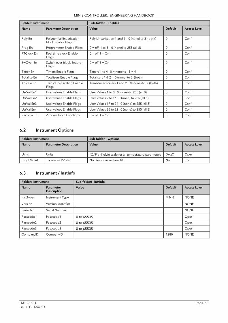
MINI8 CONTROLLER: ENGINEERING HANDBOOK
HA028581 Page 63 Issue 12 Mar 13
Folder: Instrument Sub-folder: Enables
Name
Parameter Description Value
Default Access Level
Poly En Polynomial linearisation block Enable Flags
Poly Linearisation 1 and 2 0 (none) to 3 (both) 0 Conf
Prog En Programmer Enable Flags 0 = off, 1 to 8 0 (none) to 255 (all 8) 0 Conf
RTClock En Real time clock Enable Flags
0 = off 1 = On 0 Conf
SwOver En Switch over block Enable Flags
0 = off 1 = On 0 Conf
Timer En Timers Enable Flags Timers 1 to 4 0 = none to 15 = 4 0 Conf
Totalise En Totalisers Enable Flags Totalisers 1 & 2 0 (none) to 3 (both) 0 Conf
TrScale En Transducer scaling Enable Flags
Transducer scalers 1 and 2 0 (none) to 3 (both) 0 Conf
UsrVal En1 User values Enable Flags User Values 1 to 8 0 (none) to 255 (all 8) 0 Conf
UsrVal En2 User values Enable Flags User Values 9 to 16 0 (none) to 255 (all 8) 0 Conf
UsrVal En3 User values Enable Flags User Values 17 to 24 0 (none) to 255 (all 8) 0 Conf
UsrVal En4 User values Enable Flags User Values 25 to 32 0 (none) to 255 (all 8) 0 Conf
Zirconia En Zirconia Input Functions 0 = off 1 = On 0 Conf
6.2 Instrument Options
Folder: Instrument Sub-folder: Options
Name
Parameter Description Value
Default Access Level
Units Units °C,°F or Kelvin scale for all temperature parameters DegC Oper
ProgPVstart To enable PV start No, Yes – see section 18 No Conf
6.3 Instrument / InstInfo
Folder: Instrument Sub-folder: InstInfo
Name
Parameter Description
Value
Default Access Level
InstType Instrument Type MINI8 NONE
Version Version Identifier - NONE
Serial No Serial Number NONE
Passcode1 Passcode1 0 to 65535 Oper
Passcode2 Passcode2 0 to 65535 Oper
Passcode3 Passcode3 0 to 65535 Oper
CompanyID CompanyID 1280 NONE

MINI8 CONTROLLER: ENGINEERING HANDBOOK
Page 64 HA028581 Issue 12 Mar 13
6.4 Instrument / Diagnostics This list provides fault finding diagnostic information as follows:-
Folder: Instrument Sub-folder: Diagnostics
Name Parameter Description
CPUFree This is the amount of free CPU Time left. It shows the percentage of the tasks ticks that are idle.
MinCPUFree A benchmark of the lowest reached value of the CPU free percentage.
CtrlTicks This is the number of ticks that have elapsed while the instrument was performing the control Task.
Max Con Tick A benchmark of the maximum number of ticks that have elapsed while the instrument was performing the control Task
Clear Stats Resets the instrument performance benchmarks.
ErrCount The number of errors logged since the last Clear Log. Note: If an error occurs multiple times only the first occurrence will be logged each event will increment the count.
Err1 The first error to occur
0 There is no error 1 Bad or unrecognised module ident. A module has been inserted and has a bad or unrecognised ident. Either the module is damaged or the module is unsupported.
3 Factory calibration data bad. The factory calibration data has been read from an I/O module and has not passed the checksum test. Either the module is damaged or has not been initialised.
4 Module changed for one of a different type. A module has been changed for one of a different type. The configuration may now be incorrect
10 Calibration data write error. An error has occurred when attempting to write calibration data back to an I/O module's EE.
11 Calibration data read error. An error occurred when trying to read calibration data back from the EE on an I/O module.
18 Checksum error. The checksum of the NVol Ram has failed. The NVol is considered corrupt and there the instrument configuration may be incorrect.
20 Resistive identifier error. An error occurred when reading the resistive identifier from an i/o module. The module may be damaged.
43 Invalid custom linearisation table. One of the custom linearisation tables is invalid. Either it has failed checksum tests or the table downloaded to the instrument is invalid.
55 The Instrument wiring is either invalid or corrupt.
56 Non-vol write to volatile. An attempt was made to perform a checksummed write to a non-checksummed area
58 Recipe load failure. The selected recipe failed to load
59 Bad User CT calibration data. Corrupted or invalid user calibration data for the current monitor
60 Bad Factory CT calibration data. Corrupted or invalid factory calibration data for the current monitor
Err2 The second error to occur
Err3 The third error to occur
Err4 The fourth error to occur
Err5 The fifth error to occur
Err6 The sixth error to occur
Err7 The seventh error to occur
Err8 The eight error to occur
62 to 65 Slot1 card DFC1 to DFC4 error
66 to 69 Slot2 card DFC1 to DFC4 error
70 to 73 Slot3 card DFC1 to DFC4 error
74 to 77 Slot4 card DFC1 to DFC4 error
The generic I/O DFC chip will not communicate. This could indicate a build fault.
Clear Log Clears the error log entries and count.
UserStringCount Number of User Strings Defined
UserStringCharSpace Space Available For User Strings.

MINI8 CONTROLLER: ENGINEERING HANDBOOK
HA028581 Page 65 Issue 12 Mar 13
Folder: Instrument Sub-folder: Diagnostics
Name Parameter Description
Segments Left Number of Available Program Segments
Gives the number of unused program segments. Each time a segment is allocated to a program, this value is reduced by one.
CtrlStack Control Stack Free Space (words)
The number of words of un-used stack for the control task
CommsStack Comms Stack Free Space (words)
The number of words of un-used stack for the comms task
IdleStack Idle Stack Free Space (words)
The number of words of un-used stack for the idle (background) task.
Max segments Max number of setpoint programmer segments available
MaxSegsPerProg Specifies the maximum number of segments that can be configured for a single program
CntrlOverrun Indicates the amount of control overrun.
PSUident Shows type of PSU fitted 0 = Mains 1= 24V dc
PwrFailCount Counts the number of times the instrument power has been switched off.
Cust1Name Name for custom linearisation table 1
Cust2Name Name for custom linearisation table 2
Cust3Name Name for custom linearisation table 3

MINI8 CONTROLLER: ENGINEERING HANDBOOK
Page 66 HA028581 Issue 12 Mar 13
7. Chapter 7 I/O Folder This lists the modules fitted into the instruments, all the IO channels, the fixed IO and the current monitoring.
The IO folder lists all the channels of each of the IO boards in the 4 available slots. Each board has up to 8 inputs or outputs making a maximum of 32 channels. The channels are listed under Mod1 to Mod32.
Slot Channels
1 IO.Mod.1 to IO.Mod.8
2 IO.Mod.9 to IO.Mod.16
3 IO.Mod.17 to IO.Mod.24
4 IO.Mod.25 to IO.Mod.32
Note that the current transformer input, CT3, is not included in this arrangement. There is a separate folder for current monitoring under IO.CurrentMonitor. If this board is fitted into slot 2 the IO.Mod.9 to Mod.16 would not exist.
7.1 Module ID
Folder: IO Sub-folder: ModIDs
Name
Parameter Description
Value
Default Access Level
Module1 Module1Ident 0 NoMod – No Module
24 DO8Mod – 8 logic outputs
18 RL8Mod – 8 relay outputs
60 DI8 – 8 logic inputs
90 CT3Mod – 3 current transformer inputs
131 TC8Mod – 8 thermocouple/mV inputs
133 TC4Mod – 4 thermocouple/mV inputs
173 RT4 – 4 PT100 inputs
201 AO8Mod – 8 0-20 mA outputs (Slot 4 only)
203 AO4Mod – 4 0-20 mA outputs (Slot 4 only)
0 Read Only
Module2 Module2Ident 0 Read Only
Module3 Module3Ident 0 Read Only
Module4 Module4Ident 0 Read Only
7.1.1 Modules
The content of the Mod folders depends on the type of IO module fitted in each slot. These will be covered in the following sections.

MINI8 CONTROLLER: ENGINEERING HANDBOOK
HA028581 Page 67 Issue 12 Mar 13
7.2 Logic Input
Each DI8 card provides 8 logic input channels (voltage controlled) to the system. These can be wired to provide digital inputs to any function block within the system.
7.2.1 Logic Input Parameters
Folder – IO Sub-folder Mod.1 to .32
Name Parameter Description Value Default Access Level
Ident Channel Identity LogicIn Read Only
IOType IO Type OnOff On off input Conf
Invert Sets the sense of the logic input No Yes
No inversion Inverted
No Conf
Measured Val Measured Value On/Off Value seen at the terminals
Off Read Only
PV Process Variable On/Off Value after allowing for Invert
Off Read Only

MINI8 CONTROLLER: ENGINEERING HANDBOOK
Page 68 HA028581 Issue 12 Mar 13
7.3 Logic Output
If a slot is fitted with a DO8 board then 8 channels will be available to be configured and connected to Loop outputs, alarms or other logic signals.
7.3.1 Logic Out Parameters
Folder – IO Sub-folder Mod.1 to .32
Name
Parameter Description Value
Default Access Level
Ident Channel Identity LogicOut Read Only
IOType IO Type OnOff On off output Conf
Time Prop Time proportioning output
Invert Sets the sense of the logic input or output
No Yes
No inversion Inverted
No Conf
SbyAct Action taken by output when instrument goes into Standby Mode
Off, On Continue
Switches On/Off Remains in its last state
Off Conf
The next five parameters are only shown when ‘IO Type’ = ‘Time Prop’ outputs
MinOnTime Minimum output on/off time. Prevents relays from switching too rapidly
Auto 0.01 to 150.00 seconds
Auto = 20ms. This is the fastest allowable update rate for the output
Auto Oper
DisplayHigh The maximum displayable reading 0.00 to 100.00 100.00 Oper
DisplayLow The minimum displayable reading 0.00 to 100.00 0.00 Oper
RangeHigh The maximum (electrical) input/output level
0.00 to 100.00 100 Oper
RangeLow The minimum (electrical) input/output level
0.00 to 100.00 0 Oper
Always displayed
MeasuredVal The current value of the output demand signal to the hardware including the effect of the Invert parameter.
0 1
Off On
Read only
PV This is the desired output value, before the Invert parameter is applied
0 to 100 or 0 to 1 (OnOff)
Oper
PV can be wired from the output of a function block. For example if it is used for control it may be wired from the control loop output (Ch1 Output).

MINI8 CONTROLLER: ENGINEERING HANDBOOK
HA028581 Page 69 Issue 12 Mar 13
7.3.2 Logic Output Scaling
If the output is configured for time proportioning control, it can be scaled such that a lower and upper level of PID demand signal can limit the operation of the output value.
By default, the output will be fully off for 0% power demand, fully on for 100% power demand and equal on/off times at 50% power demand. You can change these limits to suit the process. It is important to note, however, that these limits are set to safe values for the process. For example, for a heating process it may be required to maintain a minimum level of temperature. This can be achieved by applying an offset at 0% power demand which will maintain the output on for a period of time. Care must be taken to ensure that this minimum on period does not cause the process to overheat.
If Range Hi is set to a value <100% the time proportioning output will switch at a rate depending on the value - it will not switch fully on.
Similarly, if Range Lo is set to a value >0% it will not switch fully off.
Figure 7-1: Time Proportioning Output
7.3.3 Example: To Scale a Proportioning Logic Output Access level must be configuration.
In this example the output will switch on for 8% of the time when the PID demand wired to ‘PV’ signal is at 0%.
Similarly, it will remain on for 90% of the time when the demand signal is at 100%
Range Lo = 0% Output permanently off
Output state
PID Demand signal
Disp Hi eg 100%
Disp Lo eg 0%
Range Hi = 100% Output permanently on

MINI8 CONTROLLER: ENGINEERING HANDBOOK
Page 70 HA028581 Issue 12 Mar 13
7.4 Relay Output
If slot 2 and/or 3 is fitted with a RL8 board then 8 channels will be available to be configured and connected to Loop outputs, alarms or other logic signals.
7.4.1 Relay Parameters
Folder – IO Sub-folder Mod.9 to .24
Name
Parameter Description Value
Default Access Level
Ident Channel Identity Relay Read Only
IOType IO Type OnOff On off output Conf
Time Prop Time proportioning output
Invert Sets the sense of the logic input or output
No Yes
No inversion Inverted
No Conf
SbyAct Action taken by output when instrument goes into Standby Mode
Off, On Continue
Switches On/Off Remains in its last state
Off Conf
The next five parameters are only shown when ‘IO Type’ = ‘Time Prop’ outputs
MinOnTime Minimum output on/off time. Prevents relays from switching too rapidly
Auto 0.01 to 150.00 seconds
Auto = 220ms. This is the fastest allowable update rate for the output
Auto Oper
DisplayHigh The maximum displayable reading 0.00 to 100.00 100.00 Oper
DisplayLow The minimum displayable reading 0.00 to 100.00 0.00 Oper
RangeHigh The maximum (electrical) input/output level
0.00 to 100.00 100 Oper
RangeLow The minimum (electrical) input/output level
0.00 to 100.00 0 Oper
Always displayed
MeasuredVal The current value of the output demand signal to the hardware including the effect of the Invert parameter.
0 1
Off On
Read only
PV This is the desired output value, before the Invert parameter is applied
0 to 100 or 0 to 1 (OnOff)
Oper

MINI8 CONTROLLER: ENGINEERING HANDBOOK
HA028581 Page 71 Issue 12 Mar 13
7.5 Thermocouple Input
A TC4 offers 4 channels and the TC8 board offers 8 channels which may be configured as thermocouple inputs or mV inputs.
7.5.1 Thermocouple Input Parameters
Folder – IO Sub-headers: Mod .1 to .32
Name
Parameter Description Value
Default Access Level
Ident Channel Ident TCinput Read Only
IO Type IO Type Thermocouple mV
For direct t/c connection For mV inputs, usually linear, scaled to engineering units.
Conf
Lin Type Input linearisation see section 7.5.2 Conf
Units Display units used for units conversion
see section 15.1.2 Conf
Resolution Resolution XXXXX to X.XXXX Sets scaling for digital communications using the SCADA table
Conf
CJC Type To select the cold junction compensation method
Internal 0oC 45oC 50oC External Off
See description in section 7.5.3. for further details
Internal Conf
SBrk Type Sensor break type
Low Sensor break will be detected when its impedance is greater than a ‘low’ value
Conf
High Sensor break will be detected when its impedance is greater than a ‘high’ value
Off No sensor break
SBrk Alarm Sets the alarm action when a sensor break condition is detected
ManLatch Manual latching
see also the alarm Chapter 8 Alarms
Oper
NonLatch No latching
Off No sensor break alarm
AlarmAck Sensor Break alarm acknowledge
No Yes
No Oper
DisplayHigh The maximum display value in engineering units
-99999 to 99999 For IO Type mV only Limits apply to Linear and SqRoot linearisation. See 7.3.7
100 Oper
DisplayLow The minimum display value in engineering units
-99999 to 99999 0 Oper
RangeHigh The maximum (electrical) input mV
RangeLow to 70 70 Oper
RangeLow The minimum (electrical) input mV
-70 to RangeHigh 0 Oper
Fallback Fallback Strategy See also section 7.5.5.
Downscale Meas Value = Input range lo - 5% of the mV signal received from the PV input.
Conf
Upscale Meas Value = Input range Hi + 5% of the mV signal received from the PV input.
Fall Good Meas Value = Fallback PV
Fall Bad Meas Value = Fallback PV
Clip Good Meas Value = Input range Hi/lo +/- 5%
Clip Bad Meas Value = Input range Hi/lo +/- 5%

MINI8 CONTROLLER: ENGINEERING HANDBOOK
Page 72 HA028581 Issue 12 Mar 13
Folder – IO Sub-headers: Mod .1 to .32
Name
Parameter Description Value
Default Access Level
Fallback PV Fallback value See also section 7.5.5.
Instrument range Conf
Filter Time Constant
Input filter time. An input filter provides damping of the input signal. This may be necessary to prevent the effects of excessive noise on the PV input.
Off to 500:00 (hhh:mm) s:ms to hhh:mm
1s600ms Oper
Measured Val The current electrical value of the PV input R/O
PV The current value of the PV input after linearisation
Instrument range R/O
LoPoint Low Point Lower cal point (See 7.5.6) Offset at lower point Higher cal point Offset at Higher point
0.0 Oper
LoOffset Low Offset 0.0 Oper
HiPoint High Point 0.0 Oper
HiOffset High Offset 0.0 Oper
Offset Used to add a constant offset to the PV see section 7.5.7
Instrument range 0.0 Oper
CJC Temp Reads the temperature of the rear terminals at the thermocouple connection
R/O
SBrk Value Sensor break Value Used for diagnostics only, and displays the sensor break trip value
R/O
Cal State Calibration State. Calibration of the PV Input is described in section 22.5
Idle Conf
Status PV Status The current status of the PV.
0 - OK 1 - Startup 2 - SensorBreak 4 – Out of range 6 - Saturated 8 – Not Calibrated 25 – No Module
Normal operation Initial startup mode Input in sensor break PV outside operating limits Saturated input Uncalibrated channel No Module
R/O
SbrkOutput Sensor Break Output Off /On R/O

MINI8 CONTROLLER: ENGINEERING HANDBOOK
HA028581 Page 73 Issue 12 Mar 13
7.5.2 Linearisation Types and Ranges
Input Type Min Range
Max Range
Units Min Range
Max Range
Units
J Thermocouple type J -210 1200 oC -346 2192 oF K Thermocouple type K -200 1372 oC -328 2501 oF L Thermocouple type L -200 900 oC -328 1652 oF R Thermocouple type R -50 1768 oC -58 3214 oF B Thermocouple type B 0 1820 oC 32 3308 oF N Thermocouple type N -200 1300 oC -328 2372 oF T Thermocouple type T -250 400 oC -418 752 oF S Thermocouple type S -50 1768 oC -58 3214 oF PL2 Thermocouple Platinel II 0 1369 oC 32 2496 oF
C Custom Linear mV linear input -70 70 mV SqRoot Square root Custom Customised linearisation
tables
7.5.3 CJC Type
A thermocouple measures the temperature difference between the measuring junction and the reference junction. The reference junction, therefore, must either be held at a fixed known temperature or accurate compensation be used for any temperature variations of the junction.
7.5.3.1 Internal Compensation The controller is provided with a temperature sensing device which senses the temperature at the point where the thermocouple is joined to the copper wiring of the instrument and applies a corrective signal.
Where very high accuracy is needed and to accommodate multi-thermocouple installations, larger reference units are used which can achieve an accuracy of ±0.1°C or better. These units also allow the cables to the instrumentation to be run in copper. The reference units are contained basically under three techniques, Ice-Point, Hot Box and Isothermal.
7.5.3.2 The Ice-Point There are usually two methods of feeding the EMF from the thermocouple to the measuring instrumentation via the ice-point reference, the bellows type and the temperature sensor type.
The bellows type utilises the precise volumetric increase which occurs when a known quantity of ultra pure water changes state from liquid to solid. A precision cylinder actuates expansion bellows which control power to a thermoelectric cooling device. The temperature sensor type uses a metal block of high thermal conductance and mass, which is thermally insulated from ambient temperatures. The block temperature is lowered to 0°C by a cooling element, and maintained there by a temperature sensing device.
Special thermometers are obtainable for checking the 0°C reference units and alarm circuits that detect any movement from the zero position can be fitted.
7.5.3.3 The Hot Box Thermocouples are calibrated in terms of EMF generated by the measuring junctions relative to the reference junction at 0°C. Different reference points can produce different characteristics of thermocouples, therefore referencing at another temperature does present problems. However, the ability of the hot box to work at very high ambient temperatures, plus a good reliability factor has led to an increase in its usage. The unit can consist of a thermally insulated solid aluminium block in which the reference junctions are embedded.
The block temperature is controlled by a closed loop system, and a heater is used as a booster when initially switching on. This booster drops out before the reference temperature, usually between 55°C and 65°C, is reached, but the stability of the hot box temperature is now important. Measurements cannot be taken until the hot box reaches the correct temperature.
Measuring junction
Reference junction

MINI8 CONTROLLER: ENGINEERING HANDBOOK
Page 74 HA028581 Issue 12 Mar 13
7.5.3.4 Isothermal Systems The thermocouple junctions being referenced are contained in a block which is heavily thermally insulated. The junctions are allowed to follow the mean ambient temperature, which varies slowly. This variation is accurately sensed by electronic means, and a signal is produced for the associated instrumentation. The high reliability factor of this method has favoured its use for long term monitoring.
7.5.3.5 CJC Options in Mini8 Controller Series 0 – Internal CJC measurement at instrument terminals
1 – 0C CJC based on external junctions kept at 0C (Ice Point)
2 – 45C CJC based on external junctions kept at 45C (Hot Box)
3 – 50C CJC based on external junctions kept at 50C (Hot Box)
4 – External CJC based on independent external measurement
5 – Off CJC switched off
7.5.4 Sensor Break Value The controller continuously monitors the impedance of a transducer or sensor connected to any analogue input. This impedance, expressed as a % of the impedance which causes the sensor break flag to trip, is a parameter called ‘SBrkValue’.
The table below shows the typical impedance which causes sensor break to trip for various types of input and high and low SBrk Impedance readings. The impedance values are only approximate (±25%) as they are not factory calibrated.
TC4/TC8 Input Range -77 to +77mV
SBrk Impedance – High SBrk Impedance – Low
~ 12KΩ ~ 3KΩ
7.5.5 Fallback A Fallback strategy may be used to configure the default value for the PV in case of an error condition. The error may be due an out of range value, a sensor break, lack of calibration or a saturated input.
The Status parameter would indicate the error condition and could be used to diagnose the problem.
Fallback has several modes and may be associated with the Fallback PV parameter
The Fallback PV may be used to configure the value assigned to the PV in case of an error condition. The Fallback parameter should be configured accordingly.
The fallback parameter may be configured so as to force a Good or Bad status when in operation. This in turn allows the user to choose to override or allow error conditions to affect the process.

MINI8 CONTROLLER: ENGINEERING HANDBOOK
HA028581 Page 75 Issue 12 Mar 13
7.5.6 User Calibration (Two Point)
All ranges of the controller have been calibrated against traceable reference standards. However in a particular application it may be necessary to adjust the displayed reading to overcome other effects within the process. A two point calibration is offered allowing offset and slope adjustment. This is most useful where the setpoints used in a process cover a wide range. The Low and High points should be set on or near the extremities of the range.
7.5.7 PV Offset (Single Point) All ranges of the controller have been calibrated against traceable reference standards. This means that if the input type is changed it is not necessary to calibrate the controller. There may be occasions, however, when you wish to apply an offset to the standard calibration to take account of known errors within the process, for example, a known sensor error or a known error due to the positioning of the sensor. In these instances it is not advisable to change the reference calibration, but to apply a user defined offset. A single point offset is most useful where the process setpoint remains at nominally the same value. PV Offset applies a single offset over the full display range of the controller and can be adjusted in Operator Mode. It has the effect of moving the curve up a down about a central point as shown in the example below:-
7.5.7.1 Example: To Apply an Offset:-
• Connect the input of the controller to the source device which you wish to calibrate to
• Set the source to the desired calibration value
• The controller will show the current measurement of the value
• If the value is correct, the controller is correctly calibrated and no further action is necessary. If you wish to offset the reading use the Offset parameter where
Corrected value (PV) = input value + Offset.
Low offset (e.g. 1.1°)
High offset(e.g. 2.9°)
Low point (e.g. 50°)
High point(e.g. 500°)
Display Reading
Measured Reading
Factory calibration
Measured Reading
Display Reading
Fixed offset(e.g. 2.1°)
Factory calibration

MINI8 CONTROLLER: ENGINEERING HANDBOOK
Page 76 HA028581 Issue 12 Mar 13
7.5.8 Using TC4 or TC8 channel as a mV input Example – a pressure sensor provides 0 to 33mV for 0 to 200 bar.
1. Set IO type as mV
2. Set the Linearisation Type as Linear
3. Set DisplayHigh to 200 (bar)
4. Set DisplayLow to 0 (bar)
5. Set RangeHigh to 33 mV
6. Set RangeLow to 0 mV
Note maximum input range is ± 70 mV

MINI8 CONTROLLER: ENGINEERING HANDBOOK
HA028581 Page 77 Issue 12 Mar 13
7.6 Resistance Thermometer Input The RT4 module offers 4 resistance inputs which can be linear or PT100.
7.6.1 RT Input Parameters
Folder – IO Sub-headers: Mod .1 to .32
Name
Parameter Description Value
Default Access Level
Ident Channel Ident RTinput Read Only
IO Type IO Type RTD2 RTD3 RTD4
For 2 wire, 3 wire or 4 wire connections. Conf
Lin Type Linearisation Type See section 7.6.2
Conf
Units Display units used for units conversion
See section 15.1.2
Conf
Resolution Resolution XXXXX to X.XXXX
Sets scaling for digital communications using the SCADA table
Conf
SBrk Type Sensor break type
Low Sensor break will be detected when its impedance is greater than a ‘low’ value
Conf
High Sensor break will be detected when its impedance is greater than a ‘high’ value
Off No sensor break
SBrk Alarm Sets the alarm action when a sensor break condition is detected
ManLatch Manual latching see also the alarm Chapter 8 Alarms
Oper
NonLatch No latching
Off No sensor break alarm
AlarmAck Sensor Break alarm acknowledge
No Yes
No Oper
Fallback Fallback Strategy See also section 7.5.5.
Downscale Meas Value = Input range lo - 5% Conf
Upscale Meas Value = Input range Hi + 5%
Fall Good Meas Value = Fallback PV
Fall Bad Meas Value = Fallback PV
Clip Good Meas Value = Input range Hi/lo +/- 5%
Clip Bad Meas Value = Input range Hi/lo +/- 5%
Fallback PV Fallback value See also section 7.5.5.
Instrument range Conf
Filter Time Constant
Input filter time. An input filter provides damping of the input signal. This may be necessary to prevent the effects of excessive noise on the PV input.
Off to 500:00 (hhh:mm) s:ms to hhh:mm
1.6 seconds Oper
Measured Val The current electrical value of the PV input
R/O
PV The current value of the PV input after linearisation
Instrument range R/O
LoPoint Low Point Lower cal point (See section 7.5.6) Offset at lower cal point Higher cal point Offset at Higher cal point
0.0 Oper
LoOffset Low Offset 0.0 Oper
HiPoint High Point 0.0 Oper
HiOffset High Offset 0.0 Oper
Offset Used to add a constant offset to the PV see section 7.5.7
Instrument range 0.0 Oper
SBrk Value Sensor break Value Used for diagnostics only, and displays the sensor break trip value
R/O

MINI8 CONTROLLER: ENGINEERING HANDBOOK
Page 78 HA028581 Issue 12 Mar 13
Folder – IO Sub-headers: Mod .1 to .32
Name
Parameter Description Value
Default Access Level
Cal State Calibration State. Calibration of the PV Input is described in Chapter 22.5
Idle Conf
Status PV Status The current status of the PV.
0 - OK 1 - Startup 2 - SensorBreak 4 – Out of range 6 - Saturated 8 – Not Calibrated 25 – No Module
Normal operation Initial startup mode Input in sensor break PV outside operating limits Saturated input Uncalibrated channel No Module
R/O
SbrkOutput Sensor Break Output Off /On R/O
7.6.2 Linearisation Types and Ranges
Input Type Min Range
Max Range
Units Min Range Max Range Units
PT100 100 ohm platinum bulb -200 850 oC -328 1562 oF
Linear Linear 50 450 ohms
7.6.3 Using RT4 as mA input
Wire the input with a 2.49 ohm resistor as shown in 1.4.13.
The PV is mapped from the input using User Cal – see section 7.5.6
Approximate Values for 4-20mA input with 2.49 ohm resistor.
PV range
4 to 20 0 to 100
LoPoint 35.4 35.4
LoOffset -31.4 -35.4
HiPoint 169.5 169.5
HiOffset -149.5 -69.5
For best accuracy the input should be calibrated against a reference.

MINI8 CONTROLLER: ENGINEERING HANDBOOK
HA028581 Page 79 Issue 12 Mar 13
7.7 Analogue Output
The AO4 offers 4 channels and the AO8 module 8 channels which maybe configured as mA outputs. An AO4 or AO8 may only be fitted in Slot 4.
Folder – IO Sub-folder: Mod.25 to Mod.32
Name
Parameter Description Value
Default Access Level
Ident Channel ident mAout R/O
IO Type To configure the output drive signal
mA milli-amps dc Conf
Resolution Display resolution XXXXX to X.XXXX Determines scaling for SCADA communications
Conf
Disp Hi Display high reading -99999 to 99999 decimal points depend on resolution
100 Oper
Disp Lo Display low reading 0 Oper
Range Hi Electrical high input level 0 to 20 20 Oper
Range Lo Electrical low input level 4 Oper
Meas Value The current output value R/O
PV Oper
Status PV Status The current status of the PV.
0 - OK 1 - Startup 2 - SensorBreak 4 – Out of range 6 - Saturated 8 – Not Calibrated 25 – No Module
Normal operation Initial startup mode Input in sensor break PV outside operating limits Saturated input Uncalibrated channel No Module
R/O
7.7.1 Example – 4 to 20mA Analogue Output In this example 0% (=Display Low) to 100% (=Display High) from a Loop PID Output is wired to this output channel PV input which will give a 4mA (=Range Low) to 20mA (=Range High) control signal.
Here the PID demand is 50% giving a MeasuredVal output of 12mA.

MINI8 CONTROLLER: ENGINEERING HANDBOOK
Page 80 HA028581 Issue 12 Mar 13
7.8 Fixed IO
There are two digital inputs, designated D1 and D2.
Folder: IO Sub-folder: Fixed IO.D1 and .D2
Name
Parameter Description Value
Default Access Level
Ident Channel Ident LogicIn LogicIn Read Only
IO Type IO Type Input Input Read Only
Invert Invert No/Yes – input sense is inverted No Conf
Measured Val Measured Value On/Off Value seen at the terminals Off Read Only
PV Process Variable On/Off Value after allowing for Invert Off Read Only
There are two fixed relay outputs, designated A and B
Folder: IO Sub-folder: Fixed IO.A and .B
Name
Parameter Description Value
Default Access Level
Ident Channel Ident Relay Relay Read Only
IO Type IO Type OnOff OnOff Read Only
Invert Invert No/Yes = output sense is inverted. No Conf
Measured Val Measured Value On/Off Value seen at the terminals after allowing for Invert.
Off Read Only
PV Process Variable On/Off Requested output before Invert
Off Oper
SbyAct Action taken by output when instrument goes into Standby Mode
Off, On Continue
Switches On/Off Remains in its last state
Off Conf

MINI8 CONTROLLER: ENGINEERING HANDBOOK
HA028581 Page 81 Issue 12 Mar 13
7.9 Current Monitor
The Mini8 controller, with a CT3 card, has the capability of detecting failures of up to 16 heater loads by measuring the current flowing through them via 3 current transformer inputs. The failures that can be detected are:
SSR Fault If current is detected flowing through the heater when the controller is requesting it to be off then this indicates that the SSR has a short circuit fault. If current is not detected when the controller is requesting the heater to be on it indicates that the SSR has an open circuit fault.
Partial Load Fault (PLF) If less current is detected flowing through the heater than the PLF threshold, which has been set for that channel, then this indicates that the heater has a fault; in applications that use multiple heater elements in parallel then it indicates that one or more of the elements has an open circuit fault.
Over Current Fault (OCF) If more current is detected flowing through the heater than the OCF threshold then this indicates that the heater has a fault; in applications that use multiple heater elements in parallel then it indicates that one or more of the elements has lower than expected resistance value.
It should be noted that if the loop associated with a CT monitored output is inhibited, then that output will be excluded from the CT measurements and fault detection.
Heater failures are indicated via individual load status parameters and via four status words. In addition, a global alarm parameter will indicate when a new CT alarm has been detected, which, will also be registered in the alarm log.
7.9.1 Current Measurement Individual LoadCurrent parameters indicate the current measured for each heater. The Current Monitor function block utilises a cycling algorithm to measure the current flowing through one heater per measurement interval (default 10s, user alterable). Compensation within the control loop minimises the disturbance to the PV when current through a load is being measured.
The interval between successive measurements is dependent upon the average output power required to maintain SP. The recommended absolute minimum interval can be calculated as follows:
Minimum interval (s) > 0.25 * (100/average output power to maintain SP). For example, if average output power to maintain SP is 10%, using the above rule, the recommended minimum interval is 2.5 seconds. The interval may need to be adjusted depending upon the response of the heaters being used.
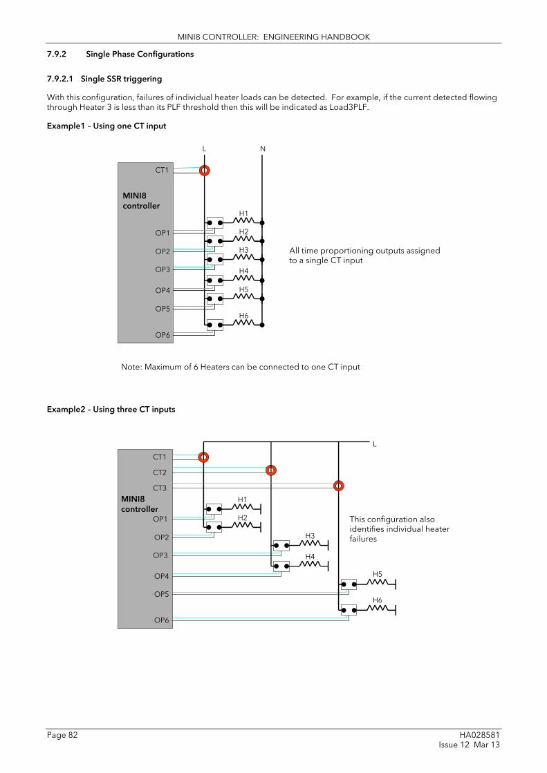
MINI8 CONTROLLER: ENGINEERING HANDBOOK
Page 82 HA028581 Issue 12 Mar 13
7.9.2 Single Phase Configurations
7.9.2.1 Single SSR triggering
With this configuration, failures of individual heater loads can be detected. For example, if the current detected flowing through Heater 3 is less than its PLF threshold then this will be indicated as Load3PLF.
Example1 – Using one CT input
Example2 – Using three CT inputs
All time proportioning outputs assigned to a single CT input
CT1
H1
H2
H3
OP1
OP2
OP3
OP4
OP5
OP6
L
H4
H5
H6
N
Note: Maximum of 6 Heaters can be connected to one CT input
MINI8 controller
This configuration also identifies individual heater failures
CT1
H1
H2
H3
OP1
OP2
OP3
OP4
OP5
OP6
MINI8 controller
L
H4
H5
H6
CT2
CT3

MINI8 CONTROLLER: ENGINEERING HANDBOOK
HA028581 Page 83 Issue 12 Mar 13
7.9.2.2 Multiple SSR triggering
With this configuration, failure of a set of heater loads can be detected. For example, if the current detected flowing through Heater Set 1 is less than Load1’s PLF threshold then this will be indicated as Load1PLF. Further investigation will then be required to determine which heater within Set 1 has failed.
7.9.2.3 Split Time Proportioning Outputs
This is where a single power demand is split and applied to two time proportioning outputs, that have been scaled, allowing the loads to switch on incrementally as the output power increases. For example, Heater1 will deliver any demand from 0-50%, and Heater2 will deliver any demand from 50-100% (with Heater1 fully on).
As the Mini8 controller has the capability of detecting faults with up to 16 heater loads it can handle this type of application even if all 8 loops have split time proportioning outputs.
CT1
H1
H2
H3
OP1
OP2
L
H4
H5
H6
N
Heater Set 1
Heater Set 2
MINI8 controller
H1
L
Loop
Mod.17
Mod.18
Pre-Scaling
0 100
Ch1Out
PV
H2
CurrentMonitor
CT1
100
50
Pre-Scaling
0 100
PV
50
0
MINI8 controller

MINI8 CONTROLLER: ENGINEERING HANDBOOK
Page 84 HA028581 Issue 12 Mar 13
7.9.3 Three Phase Configuration
Configuration for Three Phase supply applications is similar to that for Single phase using three CT inputs.
All currents passed through an individual CT must come from the same phase
Star with neutral or delta connection is possible
N/Ph
N/Ph
N/Ph
CT1
CT2
CT3 H1
H2
H3
H4
H5
H6
OP1
OP2
OP3
OP4
OP5
OP6
Ph1 Ph2 Ph3
Note: Maximum of 6 Heaters can be connected to one CT input
MINI8 controller

MINI8 CONTROLLER: ENGINEERING HANDBOOK
HA028581 Page 85 Issue 12 Mar 13
7.9.4 Parameter Configuration
If Current Monitor is enabled in the folder Instrument/Options/Current Monitor then the current monitor configuration folder appears as a subfolder in IO.
Folder: IO Sub-folder: CurrentMonitor/Config
Name
Parameter Description
Value
Default Access Level
Commission Commission CT No See section 7.9.5 Auto Manual Accept Abort
No Oper
CommissionStatus Commission Status
Not commissioned Not commissioned 0 Read Only Commissioning Commissioning in progress
NoDO8orRL8cards There are no DO8/RL8 cards installed in the instrument.
NoloopTPouts The digital outputs are either not configured as time proportioning or are not wired from loop heater channels.
SSRfault Either a SSR short circuit or open circuit fault is present.
MaxLoadsCT1/2/3
More than 6 heaters have been connected to CT input 1or 2 or 3.
NotAccepted Commissioning failed
Passed Successfully auto commissioned
ManuallyConfigured Configured manually
Interval Measurement Interval
1s to 1m 10s Oper
Inhibit Inhibit No – current is measured Yes –current measurement is inhibited
No Oper
MaxLeakPh1 Max Leakage Current Phase 1
0.25 to 1 amp 0.25 Oper
MaxLeakPh2 Max Leakage Current Phase 2
0.25 to 1 amp 0.25 Oper
MaxLeakPh3 Max Leakage Current Phase 3
0.25 to 1 amp 0.25 Oper
CT1Range* CT input 1 range
10 to 1000 amps (Ratio to 50mA) 10 Oper
CT2Range* CT input 2 range
10 to 1000 amps (Ratio to 50mA) 10 Oper
CT3Range* CT input 3 range
10 to 1000 amps (Ratio to 50mA) 10 Oper
CalibrateCT1 Calibrate CT1 Idle See section 22.5 0mA -70mA LoadFactorCal SaveUserCal
Idle Oper
CalibrateCT2 Calibrate CT2 As CT1 Idle Oper
CalibrateCT3 Calibrate CT3 As CT1 Idle Oper
• The current rating of the CT used for each of the CT input channels should cover only the single largest load current proposed for its group of heaters. e.g. if CT1 has heaters of 15A, 15A & 25A it would need a CT capable of at least 25A.

MINI8 CONTROLLER: ENGINEERING HANDBOOK
Page 86 HA028581 Issue 12 Mar 13
7.9.5 Commissioning
7.9.5.1 Auto Commission Auto commissioning of the Current Monitor is a feature that automatically detects which time proportioning outputs drive individual heaters (or heater sets), detects which CT input individual heaters are associated with and determines the Partial Load and Over Current thresholds using a 1:8 ratio. If auto commissioning fails, a status parameter indicates the reason why.
Note: In order for the auto commissioning to operate successfully the process must be enabled for full operation of the heating circuit with the digital outputs configured as Time Proportioning and ‘soft’ wired to the appropriate loop heater channels. During auto commissioning digital outputs will switch on and off.
How to Auto Commission 1. Put instrument into Operator Mode.
2. Set Commission to Auto and CommissionStatus will display ‘Commissioning’.
3. If successful, CommissionStatus will display Passed and configured load parameters will become available. If unsuccessful, CommissionStatus displays the offending fault.
If unsuccessful, CommissionStatus displays the offending fault:
NoDO8orRL8Cards Indicates that there are no DO8 or RL8 cards installed in the instrument.
NoLoopTPOuts Indicates that the digital outputs are either not configured as time proportioning or are not wired from loop heater channels.
SSRFault Indicates that either a SSR short circuit or open circuit fault is present.
MaxLoadsCT1
(or 2,3)
Indicates that more than 6 heaters have been connected to CT input 1
(or 2,3)

MINI8 CONTROLLER: ENGINEERING HANDBOOK
HA028581 Page 87 Issue 12 Mar 13
7.9.5.2 Manual Commission
Manual Commissioning is also available and is intended for those users who want to commission the Current Monitor off-line or do not want to accept auto commissioned settings.
How to Manual Commission
1. Set Commission to Manual. CommissionStatus will display Commissioning and Load1 configuration parameters will become available
2. Set Load1DrivenBy to the IO Module that is connected to the heater load.
3. Set Load1CTInput to the CT input number that is connected to the heater load.
4. Set Load1PLFthreshold and Load1OCFthreshold to appropriate values for the heater load.
5. Repeat for other loads.
6. To use the commissioned settings set Commission to ‘Accept’. CommissionStatus will display ManuallyConfigured.
7. To stop manual commissioning set Commission to ‘Abort’. CommissionStatus will display NotCommissioned.

MINI8 CONTROLLER: ENGINEERING HANDBOOK
Page 88 HA028581 Issue 12 Mar 13
7.9.6 Calibration
A Mini8 controller supplied from factory with the CT3 card already installed the CT inputs will have been factory calibrated. If the CT3 card is installed at a later date then default calibration values are automatically loaded into the instrument. However, three calibration parameters, one for each CT input, are provided to allow the inputs to be calibrated in the field.
Note: DC Current Source, capable of outputting a –70mA signal, is required to calibrate the inputs.
The 3 CT inputs are calibrated individually.
How to Calibrate 1. Apply the stimulus (0mA or –70mA) from the DC current source to the CT input to be calibrated.
2. Set CalibrateCT1, to reflect the stimulus being applied to the input.
3. CalibrateCT1 displays ‘Confirm’. Select ‘Go’ to proceed with the calibration process.
4. After selecting Go, CalibrateCT1 displays ‘Calibrating’.
5. If calibration was successful, CalibrateCT1 displays ‘Passed’. Select ‘Accept’ to keep the calibration values.
6. If calibration was unsuccessful, CalibrateCT1 displays ‘Failed’. Select ‘Abort’ to reject the calibration.
7. Select ‘SaveUserCal’ to save the calibration values into non-volatile memory.
8. Select ‘LoadFactCal’ to restore calibration values to the factory calibrated or default settings.
9. Note: It is possible to stop the calibration process at anytime by selecting ‘Abort’.
Follow the same procedure for CT2 and CT3.

MINI8 CONTROLLER: ENGINEERING HANDBOOK
HA028581 Page 89 Issue 12 Mar 13
8. Chapter 8 Alarms Alarms are used to alert the system when a pre-set level has been exceeded or a particular condition has changed state. As the Mini8 controller has no display to show alarms the alarm flags are all available over communications in status words See Alarm Summary (Section 8.7). They may also be wired directly or via logic to an output such as a relay.
Alarms can be divided into two main types. These are:-
Analogue alarms - operate by monitoring an analogue variable such as the process variable and comparing it with a set threshold.
Digital alarms – operate when the state of a boolean variable changes, for example, sensor break.
Number of Alarms - up to 32 analogue and 32 digital alarms may be configured.
8.1 Further Alarm Definitions
Hysteresis is the difference between the point at which the alarm switches ‘ON’ and the point at which it switches ‘OFF’. It is used to provide a definite indication of the alarm condition and to prevent alarm relay chatter.
Latch used to hold the alarm condition once an alarm has been detected. It may be configured as:-
None Non latching
A non latching alarm will reset itself when the alarm condition is removed
Auto Automatic An auto latching alarm requires acknowledgement before it is reset. The acknowledgement can occur BEFORE the condition causing the alarm is removed.
Manual Manual The alarm continues to be active until both the alarm condition is removed AND the alarm is acknowledged. The acknowledgement can only occur AFTER the condition causing the alarm is removed.
Event Event Alarm output will activate.
Block The alarm may be masked during start up. Blocking prevents the alarm from being activated until the process has first achieved a safe state. It is used, for example, to ignore start up conditions which are not representative of running conditions. A blocking alarm is re-initiated after a setpoint change.
Delay A short time can be set for each alarm which prevents the output from going into the alarm state. The alarm is still detected as soon as it occurs, but if it cancels before the end of the delay period then no output is triggered. The timer for the delay is then reset. It is also reset if an alarm is changed from being inhibited to uninhibited.

MINI8 CONTROLLER: ENGINEERING HANDBOOK
Page 90 HA028581 Issue 12 Mar 13
8.2 Analogue Alarms
Analogue alarms operate on variables such as PV, output levels, etc. They can be soft wired to these variables to suit the process.
8.2.1 Analogue Alarm Types
Absolute High - an alarm occurs when the PV exceeds a set high threshold. Absolute Low - an alarm occurs when the PV exceeds a set low threshold. Deviation High - an alarm occurs when the PV is higher than the setpoint by a set threshold Deviation Low - an alarm occurs when the PV is lower than the setpoint by a set threshold
Deviation Band - an alarm occurs when the PV is higher or lower than the setpoint by a set threshold
These are shown graphically below for changes in PV plotted against time. (Hysteresis set to zero)
Abs Low On On
Dev Low On On
Dev High On
Dev Bnd On On On
Abs High On
Time
Setpoint (SP)
Abs High
Abs Low
Dev High
Dev Low
Dev Bnd
PV
Process Variable (PV)
Alarm Type
Output State

MINI8 CONTROLLER: ENGINEERING HANDBOOK
HA028581 Page 91 Issue 12 Mar 13
8.3 Digital Alarms
Digital alarms operate on Boolean variables. They can be soft wired to any suitable Boolean parameter such as digital inputs or outputs.
8.3.1 Digital Alarm Types
Pos Edge The alarm will trigger when the input changes from a low to high condition
Neg Edge The alarm will trigger when the input changes from a high to low condition
Edge The alarm will trigger on any change of state of the input signal
High The alarm will trigger when the input signal is high
Low The alarm will trigger when the input signal is low
8.4 Alarm Outputs
Alarms can operate a specific output (usually a relay). Any individual alarm can operate an individual output or any combination of alarms can operate an individual output. They are wired as required in configuration level.
8.4.1 How Alarms are Indicated Alarm states are all embedded in 16 bit status words. See Alarm Summary in Section 8.7
8.4.2 To Acknowledge an Alarm Set the appropriate alarm acknowledge flag to acknowledge that particular alarm. Alternatively the GlobalAck in the AlmSummary folder can be used to acknowledge ALL alarms that require acknowledging in the instrument.
The action, which now takes place, will depend on the type of latching, which has been configured.
8.4.2.1 Non Latched Alarms If the alarm condition is present when the alarm is acknowledged, the alarm output will be continuously active. This state will continue for as long as the alarm condition remains. When the alarm condition clears the output will go off. If the alarm condition clears before it is acknowledged the alarm output goes off as soon as the condition disappears.
8.4.2.2 Automatic Latched Alarms
The alarm continues to be active until both the alarm condition is removed AND the alarm is acknowledged. The acknowledgement can occur BEFORE the condition causing the alarm is removed. 8.4.2.3 Manual Latched Alarms
The alarm continues to be active until both the alarm condition is removed AND the alarm is acknowledged. The acknowledgement can only occur AFTER the condition causing the alarm is removed.
OR
Invert Output
No
Yes
Each source may be chosen from:-
Analogue Alarms 1 to 32 Digital Alarms 1 to 32 Any alarms New alarm/ New CT Alarm Loop break alarms

MINI8 CONTROLLER: ENGINEERING HANDBOOK
Page 92 HA028581 Issue 12 Mar 13
8.5 Alarm Parameters Four groups of eight analogue alarms are available. The following table shows the parameters to set up and configure alarms.
Folder: Alarm Sub-folders: 1 to 32
Name
Parameter Description Value
Default Access Level
Type Selects the type of alarm None Alarm not configured Conf Abs Hi Full Scale High
Abs Lo Full Scale Low
Dev Hi Deviation High
Dev Lo Deviation Low
Dv Bnd Deviation band
In This is the parameter that will be monitored and compared against the threshold value to see if an alarm condition has occurred
Instrument range Oper
Reference The reference value is used in deviation alarms and the threshold is measured from this reference and not from its absolute value.
Instrument range Oper
Threshold The threshold is the value that the input is compared against to determine if an alarm has occurred.
Instrument range Oper
Out The output indicates whether the alarm is on or off depending on: the alarm condition, latching and acknowledge, inhibiting and blocking.
Off Alarm output deactivated
R/O
On Alarm output activated
Inhibit Inhibit is an input to the Alarm function. It allows the alarm to be switched OFF. Typically the Inhibit is connected to a digital input or event so that during a phase of the process alarms do not activate. For Example, if the door to a furnace is opened the alarms may be inhibited until the door is closed again.
No Yes
Alarm not inhibited Inhibit function active
Oper
Hysteresis Hysteresis is used to prevent signal noise from causing the Alarm output to oscillate. Alarm outputs become active as soon as the PV exceeds the Alarm Setpoint. They return to inactive after the PV has returned to the safe region by more than the hysteresis value. Typically the Alarm hysteresis is set to a value that is greater than the oscillations seen on the instrument display
Instrument range Oper
Latch Determine the type of latching the alarm will use, if any. Auto latching allows acknowledgement while the alarm condition is still active, whereas manual latching needs the condition to revert back to safe before the alarm can be acknowledged. See also the description at the beginning of this chapter
None No latching is used Oper
Auto Automatic
Manual Manual
Event Event
Ack Used in conjunction with the latching parameter. It is set when the user responds to an alarm.
No Yes
Not acknowledged Acknowledged
Oper
Block Alarm Blocking is used to prevent alarms from activating during start-up. In some applications, the measurement at start-up is in an alarm condition until the system has come under control. Blocking causes the alarms to be ignored until the system is under control (in the safe state), after this any deviations trigger the alarm
No Yes
No blocking Blocking
Oper
Delay This is a small delay between sensing the alarm condition and displaying it. If in the time between the two, the alarm goes safe, then no alarm is shown and the delay timer is reset. It can be used on systems that are prone to noise.
0:00.0 to 500 mm:ss.s hh:mm:ss hhh:mm
0:00.0 Oper

MINI8 CONTROLLER: ENGINEERING HANDBOOK
HA028581 Page 93 Issue 12 Mar 13
8.5.1 Example: To Configure Alarm 1
Change Access level to configuration.
In this example the high alarm will be detected when the measured value exceeds 100.00.
The current measured value is 27.79 as measured by the ‘Input’ parameter. This parameter will normally be wired to an internal source such as a thermocouple input. In this example the alarm will set when the measured value exceeds the threshold 100.0 and will clear when the input decreases 0.50 units below the threshold level (i.e. at 99.5 units).

MINI8 CONTROLLER: ENGINEERING HANDBOOK
Page 94 HA028581 Issue 12 Mar 13
8.6 Digital Alarm Parameters
Four groups of eight digital alarms are available. The following table shows the parameters to set up and configure alarms.
Folder: DigAlarm Sub-folders: 1 to 32
Name
Parameter Description Value
Default Access Level
Type Selects the type of alarm None Alarm not configured Conf PosEdge On rising edge
NegEdge On falling edge
Edge On change
High High (1)
Low Low (0)
In This is the parameter that will be monitored and checked according to the AlarmType to see if an alarm condition has occurred
0 to 1 Oper
Out The output indicates whether the alarm is on or off depending on: the alarm condition, latching and acknowledge, inhibiting and blocking.
Off Alarm output deactivated
R/O
On Alarm output activated
Inhibit Inhibit is an input to the Alarm function. It allows the alarm to be switched OFF. Typically the Inhibit is connected to a digital input or event so that during a phase of the process alarms do not activate. For Example, if the door to a furnace is opened the alarms may be inhibited until the door is closed again.
No Yes
Alarm not inhibited Inhibit function active
Oper
Latch Determine the type of latching the alarm will use, if any. Auto latching allows acknowledgement while the alarm condition is still active, whereas manual latching needs the condition to revert back to safe before the alarm can be acknowledged. See also the description at the beginning of this chapter
None No latching is used Oper
Auto Automatic
Manual Manual
Event Event
Ack Used in conjunction with the latching parameter. It is set when the user responds to an alarm.
No Yes
Not acknowledged Acknowledged
Oper
Block Alarm Blocking is used to prevent alarms from activating during start-up. In some applications, the measurement at start-up is in an alarm condition until the system has come under control. Blocking causes the alarms to be ignored until the system is under control (in the safe state), after this any deviations trigger the alarm
No Yes
No blocking Blocking
Oper
Delay This is a small delay between sensing the alarm condition and displaying it. If in the time between the two, the alarm goes safe, then no alarm is shown and the delay timer is reset. It can be used on systems that are prone to noise.
0:00.0 to 500 mm:ss.s hh:mm:ss hhh:mm
0:00.0 Oper
8.6.1 Example: To Configure DigAlarm 1
Change Access level to configuration.
In this example the digital alarm will come on if Timer 1 expires.
Timer.1.Out is wired to the alarm input. The DigAlarm.1.Out will turn on if the timer expires.

MINI8 CONTROLLER: ENGINEERING HANDBOOK
HA028581 Page 95 Issue 12 Mar 13
8.7 Alarm Summary
This is a summary of all the alarms in the Mini8 controller. It provides global alarm and acknowledge flags as well as 16 bit status words which can be read over communications by the supervisory system.
Folder: AlmSummary Sub-folders: General
Name
Parameter Description Value
Default Access Level
NewAlarm A new alarm has occurred since the last reset (excludes CT alarms)
Off/On R/O
RstNewAlarm Resets the NewAlarm flag Yes / No No Oper
NewCTAlarm A new Current alarm has occurred since the last reset
Off/On R/O
RstNewCTAlarm Resets the NewCTAlarm flag Yes / No No Oper
AnyAlarm Any new alarm since the last reset Off/On R/O
GlobalAck Acknowledges every alarm in the Mini8 controller requiring acknowledgement. Also resets NewAlarm and NewCTAlarm flags.
No Yes
Not acknowledged Acknowledged
Oper
AnAlarmStatus1 16 bit word for analogue alarms 1 to 8 Bit 0 Bit 1 Bit 2 Bit 3 Bit 4 Bit 5 Bit 6 Bit 7 Bit 8 Bit 9 Bit 10 Bit 11 Bit 12 Bit 13 Bit 14 Bit 15
Alarm 1 active Alarm 1 not ack’d Alarm 2 active Alarm 2 not ack’d Alarm 3 active Alarm 3 not ack’d Alarm 4 active Alarm 4 not ack’d Alarm 5 active Alarm 5 not ack’d Alarm 6 active Alarm 6 not ack’d Alarm 7 active Alarm 7 not ack’d Alarm 8 active Alarm 8 not ack’d
R/O
AnAlarmStatus2 16 bit word for analogue alarms 9 to 16
Same format as above R/O
AnAlarmStatus3 16 bit word for analogue alarms 17 to 24
Same format as above R/O
AnAlarmStatus4 16 bit word for analogue alarms 25 to 32
Same format as above R/O
DigAlarmStatus1 16 bit word for digital alarms 1 to 8 Bit 0 Bit 1 Bit 2 Bit 3 Bit 4 Bit 5 Bit 6 Bit 7 Bit 8 Bit 9 Bit 10 Bit 11 Bit 12 Bit 13 Bit 14 Bit 15
Alarm 1 active Alarm 1 not ack’d Alarm 2 active Alarm 2 not ack’d Alarm 3 active Alarm 3 not ack’d Alarm 4 active Alarm 4 not ack’d Alarm 5 active Alarm 5 not ack’d Alarm 6 active Alarm 6 not ack’d Alarm 7 active Alarm 7 not ack’d Alarm 8 active Alarm 8 not ack’d
R/O
DigAlarmStatus2 16 bit word for digital alarms 9 to 16 Same format as above R/O
DigAlarmStatus3 16 bit word for digital alarms 17 to 24 Same format as above R/O
DigAlarmStatus4 16 bit word for digital alarms 25 to 32 Same format as above R/O

MINI8 CONTROLLER: ENGINEERING HANDBOOK
Page 96 HA028581 Issue 12 Mar 13
Folder: AlmSummary Sub-folders: General
Name
Parameter Description Value
Default Access Level
SBrkAlarmStatus1 16 bit word for IO channels Mod.1 to 8 Bit 0 Bit 1 Bit 2 Bit 3 Bit 4 Bit 5 Bit 6 Bit 7 Bit 8 Bit 9 Bit 10 Bit 11 Bit 12 Bit 13 Bit 14 Bit 15
Mod.1 fault Alarm 1 not ack’d Mod.2 fault Alarm 2 not ack’d Mod.3 fault Alarm 3 not ack’d Mod.4 fault Alarm 4 not ack’d Mod.5 fault Alarm 5 not ack’d Mod.6 fault Alarm 6 not ack’d Mod.7 fault Alarm 7 not ack’d Mod.8 fault Alarm 8 not ack’d
R/O
SbrkAlarmStatus2 16 bit word for IO channels Mod.9 to 16
Same format as above R/O
SbrkAlarmStatus3 16 bit word for IO channels Mod.17 to 24
Same format as above R/O
SbrkAlarmStatus4 16 bit word for IO channels Mod.25 to 32
Same format as above R/O
CTAlarmStatus1 16 bit word for CT alarms 1 to 5 Bit 0 Bit 1 Bit 2 Bit 3 Bit 4 Bit 5 Bit 6 Bit 7 Bit 8 Bit 9 Bit 10 Bit 11 Bit 12 Bit 13 Bit 14 Bit 15
Load1 SSR fail Load1 PLF Load1 OCF Load2 SSR fail Load2 PLF Load2 OCF Load3 SSR fail Load3 PLF Load3 OCF Load4 SSR fail Load4 PLF Load4 OCF Load5 SSR fail Load5 PLF Load5 OCF -
R/O
CTAlarmStatus2 16 bit word for CT alarms 6 to 10 Bit 0 Bit 1 Bit 2 Bit 3 Bit 4 Bit 5 Bit 6 Bit 7 Bit 8 Bit 9 Bit 10 Bit 11 Bit 12 Bit 13 Bit 14 Bit 15
Load6 SSR fail Load6 PLF Load6 OCF Load7 SSR fail Load7 PLF Load7 OCF Load8 SSR fail Load8 PLF Load8 OCF Load9 SSR fail Load9 PLF Load9 OCF Load10 SSR fail Load10 PLF Load10 OCF -
R/O
CTAlarmStatus3 16 bit word for CT alarms 11 to 15 Same format as CTAlarmStatus1 R/O
CTAlarmStatus4 16 bit word for CT alarm 16 Same format as CTAlarmStatus1 R/O

MINI8 CONTROLLER: ENGINEERING HANDBOOK
HA028581 Page 97 Issue 12 Mar 13
8.8 Alarm Log
A list of the last 32 alarms to have occurred is maintained in an Alarm Log.
Folder: AlmSummary Sub-folder: AlmLog
Name
Parameter Description Value
Default Access Level
ClearLog Clear Alarm Log Yes/No No Oper
Entry1Ident Most recent alarm activation All analogue alarms All digital alarms All sensor break alarms All current alarms
NoEntry R/O
Entry1Day The day the first entry activated NoEntry, Monday/Tuesday…Sunday.
NoEntry R/O
Entry1Time The time the first entry activated hh:mm:ss 0 R/O
Entry2Ident 2nd most recent alarm activation All analogue alarms All digital alarms All sensor break alarms All current alarms
NoEntry R/O
Entry2Day The day the second entry activated NoEntry, Monday/Tuesday…Sunday.
NoEntry R/O
Entry2Time The time the second entry activated hh:mm:ss 0 R/O
…etc
Entry32Ident 32nd most recent alarm activation All analogue alarms All digital alarms All sensor break alarms All current alarms
NoEntry R/O
Entry32Day The day the 32nd entry activated NoEntry, Monday/Tuesday…Sunday.
NoEntry R/O
Entry32Time The time the 32nd entry activated hh:mm:ss 0 R/O
Note that EntryDay and EntryTime parameters require the Real Time Clock to be set up (Section 11.4) to record meaningful values.

MINI8 CONTROLLER: ENGINEERING HANDBOOK
Page 98 HA028581 Issue 12 Mar 13
9. Chapter 9 BCD Input The Binary Coded Decimal (BCD) input function block uses a number of digital inputs and combines them to make a numeric value. A very common use for this feature is to select a setpoint program number from panel mounted BCD decade switches.
The block uses 4 bits to generate a single digit.
Two groups of four bits are used to generate a two digit value (0 to 99)
The block outputs four results
1. Units Value: The BCD value taken from the first four bits (range 0 – 9)
2. Tens Value: The BCD value taken from the second four bits (range 0 – 9)
3. BCD Value: The combined BCD value taken from all 8 bits (range 0 – 99)
4. Decimal Value: The decimal numeric equivalent of Hexadecimal bits (range 0 – 255)
The following table shows how the input bits combine to make the output values.
Input 1
Units value ( 0 – 9)
BCD value (0 – 99)
Decimal value (0 – 255)
Input 2
Input 3
Input 4
Input 5
Tens value ( 0 – 9) Input 6
Input 7
Input 8
Since the inputs cannot all be guaranteed to change simultaneously, the output will only update after all the inputs have been stable for two samples.
9.1 BCD Parameters
Folder – BCDInput Sub-Folders: 1 and 2
Name
Parameter Description Value
Default Access Level
In 1 Digital Input 1 On or Off Alterable from the operator interface if not wired
Off Oper
In 2 Digital Input 2 On or Off Off Oper
In 3 Digital Input 3 On or Off Off Oper
In 4 Digital Input 4 On or Off Off Oper
In 5 Digital Input 5 On or Off Off Oper
In 6 Digital Input 6 On or Off Off Oper
In 7 Digital Input 7 On or Off Off Oper
In 8 Digital Input 8 On or Off Off Oper
Dec Value Decimal value of the inputs 0 – 255 See examples below R/O
BCD Value Reads the value (in BCD) of the switch as it appears on the digital inputs
0 – 99 See examples below
Units Units value of the first switch 0 – 9 See examples below R/O
Tens Units value of the second switch
0 – 9 See examples below R/O
In 1 In 2 In 3 In 4 In 5 In 6 In 7 In 8 Dec BCD Units Tens
1 0 0 0 0 0 0 0 1 1 1 0
1 1 1 1 0 0 0 0 15 9 9 0
0 0 0 0 1 1 1 1 240 90 0 9
1 1 1 1 1 1 1 1 255 99 9 9

MINI8 CONTROLLER: ENGINEERING HANDBOOK
HA028581 Page 99 Issue 12 Mar 13
9.1.1 Example: To wire a BCD Input The BCD digital input parameters may be wired to digital input terminals of the controller. A DI8 module may be used and there are also two standard digital input terminals in FixedIO, D1 and D2.
This example shows a BCD switch selecting one of eight values, In1 to In8 on the Mux8.

MINI8 CONTROLLER: ENGINEERING HANDBOOK
Page 100 HA028581 Issue 12 Mar 13
10. Chapter 10 Digital Communications Digital Communications (or ‘comms’ for short) allows the Mini8 controller to be part of a system by communicating with a PC or a programmable logic controller (PLC).
The Mini8 controller also has a configuration port for ‘cloning’ or saving/loading instrument configurations for future expansion of the plant or to allow you to recover a system after a fault.
10.1 Configuration Port (CC) The configuration port is on an RJ11 socket, just to the right of the power supply connections. This will normally be connected to a personal computer running iTools. Eurotherm supply a standard cable to connect a serial COM port on a computer to the RJ11 socket, part no. SubMini8/cable/config.
This port conforms to MODBUS RTU ® protocol a full description of which can be found on www.modbus.org.
Pin connections for the RJ11 connector are shown in section 1.4.4
10.1.1 Configuration Communications Parameters
Folder - Comms Sub-folders: CC (Config Comms)
Name Parameter Description Value Default Access Level
Ident Identification of the module fitted.
Modbus always. Modbus non-iso
R/O
Protocol Digital communications protocol
Modbus always MODBUS R/O
Baud Communications baud rate 4800 9600 19k2 (19200)
19200 Conf
Parity Communications parity None Even Odd
No parity Even parity Odd parity
None Conf
Address Instrument address 1 to 254 1 Oper
Wait Rx/tx wait states No Yes
No delay Fixed delay. This inserts a delay between Rx and Tx to ensure that the drivers used by intelligent RS232/RS485 converters have sufficient time to switch over.
No Conf
When connecting to iTools the instrument on this port will be found at address 255. iTools will also optimise the baud rate to suit the conditions.
This port can be used as a ‘permanent’ connection but it is limited to one instrument, it is a RS232 point to point connection.
Configuration is also possible through the Field Communications port but ONLY if that port is Modbus or ModbusTCP. In that situation the Mini8 controllers can be multi-dropped to iTools.
10.2 Field Communications Port (FC)
The Min8 controller has a number of communication options. These have to be ordered from the factory as part of the instrument build. A change of protocol is not usually possible in the field. The physical port and the connections will vary depending on the field communications protocol. These are shown in the wiring section of the manual section 1.4. Mini8 controller version 1.xx offers Modbus and DeviceNet, Version 2.xx adds CANopen, Profibus, EtherNet Modbus-TCP and EtherNet/IP. These protocols are described in the following sections.
10.2.1 Communications Identity
The instrument recognizes the type of communication board fitted. The identity ‘Ident’ is displayed to show that the instrument is built as required.

MINI8 CONTROLLER: ENGINEERING HANDBOOK
HA028581 Page 101 Issue 12 Mar 13
10.3 Modbus This port conforms to MODBUS RTU ® protocol a full description of which can be found on www.modbus.org.
10.3.1 Modbus Connections This uses two parallel RJ45 connectors for use with screened Cat5e patch cables. The connection is usually 2 wire but 4 wire is also available. This is selected by the top switch of the address switches below the RJ45 ports – OFF (to the left) 2 wire, ON (to the right) 4 wire.
RJ45 pin connections are shown in section 1.4.6
10.3.2 Modbus Address Switch On a network of instruments an address is used to specify a particular instrument. Each instrument on a network MUST have a unique address. Address 255 is reserved for configuration using the configuration port or the configuration clip
The switch is situated at the bottom of the Comms module. The switch gives addresses from 1 to 31. If Address 0 is set the Mini8 controller will then take the address and parity settings entered in the configuration of the instrument, see section 10.4.2. This allows for addresses above 31.
Sw OFF ON
8 3 wire 4 wire
7 NO Parity Parity
6 Even Odd
5 - Address 16
4 - Address 8
3 - Address 4
2 - Address 2
1 - Address 1
10.3.3 Baud Rate The baud rate of a communications network specifies the speed that data is transferred between instrument and master. A baud rate of 9600 equates to 9600 Bits per second. Since a single character requires 8 bits of data plus start, stop, and optional parity, up to 11 bits per byte may be transmitted. 9600 baud equates approximately to 1000 Bytes per second. 4800 baud is half the speed – approx. 500 Bytes per second.
In calculating the speed of communications in your system it is often the Latency between a message being sent and a reply being started that dominates the speed of the network.
For example, if a message consists of 10 characters (10msec at 9600 Baud) and the reply consists of 10 characters, then the transmission time would be 20 msec. However, if the Latency is 20msec, then the transmission time has become 40msec.
Baud rate is set in the parameter list see section 10.4.2.
10.3.4 Parity
Parity is a method of ensuring that the data transferred between devices has not been corrupted.
Parity is the lowest form of integrity in the message. It ensures that a single byte contains either an even or an odd number of ones or zero in the data.
In industrial protocols, there are usually layers of checking to ensure that the first byte transmitted is good. Modbus applies a CRC (Cyclic Redundancy Check) to the data to ensure that the package is correct.
Parity is set in the parameter list see section 10.4.2.
10.3.5 RX/TX Delay Time In some systems it is necessary to introduce a delay between the instrument receiving a message and its reply. This is sometimes caused by communications converter boxes which require a period of silence on the transmission to switch over the direction of their drivers.
Example shows 4 wire and address 1
OFF ↔ ON
1 2
3
4
5 6
7
8
ON

MINI8 CONTROLLER: ENGINEERING HANDBOOK
Page 102 HA028581 Issue 12 Mar 13
10.4 Modbus Broadcast Master Communications
Broadcast master communications allow the Mini8 controllers to send a single value to any slave instruments using a Modbus broadcast using function code 6 (Write single value). This allows the Mini8 controller to link through digital communications with other products without the need for a supervisory PC to create a small system solution.
Example applications include multi-zone profiling applications or cascade control using a second controller. The facility provides a simple and precise alternative to analogue retransmission.
! Warning
When using broadcast master communications, be aware that updated values are sent many times a second. Before using this facility, check that the instrument to which you wish to send values can accept continuous writes. Note that in common with many third party lower cost units, the Eurotherm 2200 series and the 3200 series prior to version V1.10 do not accept continuous writes to the temperature setpoint. Damage to the internal non-volatile memory could result from the use of this function. If in any doubt, contact the manufacturer of the device in question for advice.
When using the 3200 series fitted software version 1.10 and greater, use the Remote Setpoint variable at Modbus address 26 if you need to write to a temperature setpoint. This has no write restrictions and may also have a local trim value applied. There is no restriction on writing to the 2400, 3500 or Mini8 controller series.
10.4.1 Mini8 Controller Broadcast Master The Mini8 controller broadcast master can be connected to up to 31 slaves if no segment repeaters are used. If repeaters are used to provide additional segments, 32 slaves are permitted in each new segment. The master is configured by selecting a Modbus register address to which a value is to be sent. The value to send is selected by wiring it to the Broadcast Value. Once the function has been enabled, the instrument will send this value out over the communications link every control cycle typically every 110ms.
Notes:-
1. The parameter being broadcast must be set to the same decimal point resolution in both master and slave instruments.
2. If iTools, or any other Modbus master, is connected to the port on which the broadcast master is enabled, then the broadcast is temporarily inhibited. It will restart approximately 30 seconds after iTools is removed. This is to allow reconfiguration of the instrument using iTools even when broadcast master communications is operating.
A typical example might be a multi zone application where the setpoint of each zone is required to follow, with digital accuracy, the setpoint of a master.
Figure 10-1: Broadcast Comms
Wiring Connections for Broadcast Communications are shown in section 1.4.6.3.
Master
Min8 1
Mini8 2
Mini8 31

MINI8 CONTROLLER: ENGINEERING HANDBOOK
HA028581 Page 103 Issue 12 Mar 13
10.4.2 Modbus Parameters The following table shows the parameters available for Modbus.
Folder – Comms Sub-folder: FC (Field Communications)
Name Parameter Description Value Default Access Level
Ident Comms Module Identity Modbus Modbus Read only
Protocol Digital communications protocol
Modbus Modbus Read only
Baud Communications baud rate Modbus: 4800, 9600 or 19k2 (19200) 9600 Conf
Parity Communications parity None Even Odd
No parity Even parity Odd parity
None Conf
Address Instrument address 1 to 254 Only writable if DIP switches are set to Off.
1 Oper
Wait Rx/tx delay time No Yes
No delay Fixed delay. This inserts a delay between Rx and Tx to ensure that the drivers used by intelligent RS232/RS485 converters have sufficient time to switch over.
No Conf
Broadcast Enabled
To enable broadcast master communications. (See section 10.4)
No Yes
Not enabled Enabled
No
Broadcast Address
Address of the parameter being written to slaves.
0 to 32767
See Appendix A for addresses of all Mini8 controller parameters.
0 Only shown if Broadcast is enabled.
Broadcast Value
Value to be sent to instruments on the network. This would normally be wired to a parameter within the master.
Range of the parameter wired. In the case of a Boolean the value will be 0 or 1.
0.00 Only shown if Broadcast is enabled.
WDFlag Network watchdog flag Off This flag is ON when the Network communications have stopped addressing this instrument for longer than the Timeout time. It will be set by the Watchdog process and may be cleared Automatically or Manually according to the value of the Watchdog Action parameter.
On
WDAct Network watchdog action. The Watchdog Flag may be cleared Automatically upon reception of valid messages or Manually by a parameter write or a wired value.
Man The Watchdog Flag must be cleared manually - either by a parameter write or a wired value.
Conf
Auto The Watchdog Flag will be automatically cleared when the Network Comms resume - according to the value in the Recovery Timer.
WDTime Network Watchdog Timeout If the Network communications stop addressing the instrument for longer than this value, the Watchdog Flag will become active.
h:m:s:ms A value of 0 disables the watchdog
Conf

MINI8 CONTROLLER: ENGINEERING HANDBOOK
Page 104 HA028581 Issue 12 Mar 13
10.5 DeviceNet
Only 2 parameters have to be set on the Mini8 controller for use with DeviceNet, baud rate and address. Both can be set on the hardware address switch situated under the DeviceNet connector. Each Mini8 controller must have a unique address on the DeviceNet network and all units must be set to the same Baud rate. The switch gives addresses from 0 to 63.
Sw OFF ON
8 Baud rate Baud rate
Baud rate Baud rate
6 - Address 32
5 - Address 16
4 - Address 8
3 - Address 4
2 - Address 2
1 - Address 1
Sw Baud rate
125k 250k 500k
8 OFF OFF ON
7 OFF ON OFF
10.6 Enhanced DeviceNet Interface See also section 1.4.8. In this version of DeviceNet the slider switch is replaced by rotary BCD switches to set Node ID (address) and Baud Rate.
10.6.1 Address Switch The Node ID (address) is set via two BCD rotary switches, one for each digit.
For example, an address of 13 is configured by setting the MSD to 1 and LSD to 3.
Valid DeviceNet address range is 0 - 63. If the switches are set in the range 64 - 99 the value will be ignored and the node address will be configured by the Mini8 Controller via iTools.
When the address is changed the DeviceNet interface will automatically restart.
10.6.2 Baud Switch The baud rate is selected by a single BCD rotary switch, and can be set to 125K, 250K or 500K. The ‘Prog’ position is selected when it is required to upgrade the Mini8 Controller firmware. The O/R position is selected when it is required to set Baud Rate using iTools configuration software.
When the baud rate is changed or the ‘Prog’ position is selected the instrument must be power cycled for the change to be activated.
Make sure that the switch is set to valid positions as marked on the panel.
10.7 Switch Position in iTools The value of the Baud Rate and Address is returned so that it can be read by iTools.
Please note, however, that if the DeviceNet network is unpowered for any reason, any changes to the Baud Rate and Address will NOT be seen in iTools even though the Mini8 Controller is powered and communicating normally via the CC port or config clip.
1234
56
7 8 90
1234
56
7 8 90
Prog500
250
125
Address 0 is a valid DeviceNet address but Mini8 Controller addresses can be set via iTools, when all switches are set to 0.
Use 500k unless the total length of the DeviceNet network is longer than 100m.
OFF ↔ ON
1 2
3
4
5 6
7
8
ON
Example shows 500k baud rate and address 5

MINI8 CONTROLLER: ENGINEERING HANDBOOK
HA028581 Page 105 Issue 12 Mar 13
10.7.1 DeviceNet Parameters
Folder – Comms Sub-folder: FC (Field Communications)
Name Parameter Description Value Default Access Level
Ident Comms Module Identity DeviceNet DeviceNet Enhanced DeviceNet Read only
Protocol Digital communications protocol
DeviceNet DeviceNet Read only
Baud Communications baud rate
125k, 250k, 500k 125k Conf
Address Instrument address 0 to 63 Only writable if DIP switches are set to Off.
1 Oper
Status Comms network status Offline Network Offline Read only
Init Network Initialising
Ready Network ready to accept connection
Running Network connected and running
Online The device is on line and has connections in the Established state.
IO Timeout
One or more IO connections have timed out.
Link fail Critical link failure: an error has been detected that has made the module incapable of communicating.
Comm fault
Comms port is in the faulted condition and has accepted an Identify Comms Fault Request
WDFlag Network watchdog flag Off This flag is ON when the Network communications have stopped addressing this instrument for longer than the Timeout time. It will be set by the Watchdog process and may be cleared Automatically or Manually according to the value of the Watchdog Action parameter.
On
WDAct Network watchdog action. The Watchdog Flag may be cleared Automatically upon reception of valid messages or Manually by a parameter write or a wired value.
Man The Watchdog Flag must be cleared manually - either by a parameter write or a wired value.
Conf
Auto The Watchdog Flag will be automatically cleared when the Network Comms resume - according to the value in the Recovery Timer.
WDTime Network Watchdog Timeout If the Network communications stop addressing the instrument for longer than this value, the Watchdog Flag will become active.
h:m:s:ms A value of 0 disables the watchdog
Conf

MINI8 CONTROLLER: ENGINEERING HANDBOOK
Page 106 HA028581 Issue 12 Mar 13
10.8 CANopen
Note: from July 09 CANopen option has been discontinued. It is included here for existing systems.
10.8.1 Instrument setup
Up to 127 Nodes can be connected to a standard CANopen Network, for nodes 1 – 31 the address can be set via the comms DIP switches. For nodes 32 – 127 the address switches must be set to OFF making the Address parameter alterable in the Config Comms List, which then can be used to set the Node address.
Sw OFF ON
8 Baud rate Baud rate
7 Baud rate Baud rate
6 - Address 32
5 - Address 16
4 - Address 8
3 - Address 4
2 - Address 2
1 - Address 1
Sw Baud rate
125k 250k 500k 1M
8 OFF OFF ON ON 7 OFF ON OFF ON
A standard CANopen Network is designed to work at data transfer rates of up to 1Mbits/s (depending upon bus length). Four baud rate settings are set on the comms DIP switches: 125K, 250K, 500K and 1M.
10.8.2 Mini8 Controller CANopen Features The main features of the Mini8 controller CANopen Slave Interface are:
• CANopen-to-Modbus Gateway • Generic Device • 4 Receive PDOs (dynamic) • 4 Transmit PDOs (dynamic) • PDO communication and mapping object values can be stored in non-volatile memory • 1 Server SDO • 200 Parameter Pick List (re-definable) • PDO Mappings cloneable via CommsTab function block
CANopen is a higher layer object based CAN network protocol that supports direct access to device parameters, transmission of time critical process data and network management diagnostics via a standardised object dictionary.
The generic CANopen model shows that the device (Node) is connected to a CAN network on one side and application specific I/O data on the other.
OFF ↔ ON
1 2
3
4
5 6
7
8
ON
Example shows 1M baud rate and address 4

MINI8 CONTROLLER: ENGINEERING HANDBOOK
HA028581 Page 107 Issue 12 Mar 13
10.8.3 Communication Interface
CANopen is based on communication profiles, which specifies the basic communication mechanisms (PDOs, SDOs and NMT messages) and an object directory that specifies device parameters and functions.
10.8.3.1 Object Dictionary The object dictionary is divided into a section containing general device information (device identification, manufacturer name etc), communication parameters, and a section that describes the specific device data/functionality whether by a device profile (part of CANopen specifications) or manufacturer specified.
Index Description Range
0000h Reserved
Data Types 0001h – 025Fh Data Type Definitions
0260h – 0FFFh Reserved
1000h – 1FFFh General communication parameters
Communication Profile
1200h – 127Fh Communication parameters for server SDOs
1280h – 12FFh Communication parameters for client SDOs
1300h – 13FFh Reserved
1400h – 15FFh Communication parameters for receive PDOs
1600h – 17FFh Mapping parameter for receive PDOs
1800h – 19FFh Communication parameters for transmit PDOs
1A00h – 1BFFh Mapping parameter for transmit PDOs
1C00h – 1FFFh Reserved for extensions (i.e. DSP-302)
2000h – 5FFFh Manufacturer Specific Profile objects Application Objects
6000h – 9FFFh Standardised Device Profiles
A000h - BFFFh Interface profile specific objects Interface Profile
C000h - FFFFh Reserved
10.8.3.2 Process Data Objects (PDOs) The transfer of process data between devices on a network is the main purpose of a CAN-based communication system. In CANopen, this is performed by PDOs, which map process data from an application object(s) (similar to DeviceNet Class 0x64) into communication objects (similar to DeviceNet Class 0x66).
PDOs are separated into two groups, Transmit PDOs and Receive PDOs. Each PDO message is capable of containing 8 bytes of data (four 16-bit scaled integer parameters). Transmit PDOs are typically used to transmit critical instrument data to other nodes on the network, for example, alarm status’. Receive PDOs are typically used to configure instrument settings, for example, TargetSP.
For the Mini8 controller the number of PDOs is limited to 4 transmit PDOs and 4 receive PDOs, giving a maximum of 16 transmit and 16 receive scaled integer parameters.
Note Transmit PDO = transmitted from the Mini8 (READ), Receive PDO = received by Mini8 (WRITE).
10.8.3.3 Service Data Objects (SDOs) To access entries in the Object dictionary CANopen uses SDOs, peer to peer communication channels (similar to explicit messaging in DeviceNet), generally used during system configuration or to request non-critical process data.
This gives access to Network Management, Device & Manufacturer Information, Error Messages, Reconfiguration and control of PDOs, Store & restore of configuration, Heartbeat & Node Guarding,

MINI8 CONTROLLER: ENGINEERING HANDBOOK
Page 108 HA028581 Issue 12 Mar 13
10.8.4 Network Management (NMT)
CANopen slave nodes include the following state machine, which allows the slaves to be in different operating states.
Transitions between some states are made automatically by the slaves themselves, whereas others can only be made upon receiving the corresponding NMT Master message.
Upon power-up the slave node comes out of the Power-On Reset state and goes into initialisation. It then initialises the application and communication interface. It then attempts to transmit a boot-up message. When the boot-up message has been successfully transmitted the node enters the Pre-Operational state where it is possible for the network master to configure individual nodes via SDO messages. The master can then switch individual nodes or all nodes to the Operational state (allowing PDO communications i.e. the running state) or the Stopped state.
Initialisation Boot Up
FC LED: Off
Pre-operational SDO communications
Emergency
Heartbeat/Node Guard
Sync
FC LED: blinking
Stopped Heartbeat/Node Guard
FC LED: Off
Operational PDO communications
SDO communications
Heartbeat/NG
Emergency
Sync
FC LED: On

MINI8 CONTROLLER: ENGINEERING HANDBOOK
HA028581 Page 109 Issue 12 Mar 13
10.8.4.1 Heartbeat & Node Guarding The Mini8 controller interface supports both Node Guarding and the Heartbeat Protocol. With Node Guarding it is the responsibility of a Master device to guard (poll) all connected slaves for their current NMT state. With the Heartbeat method, each slave device transmits a heartbeat (a 1-byte message containing the current NMT state) periodically.
The Heartbeat protocol is the most widely used.
10.8.4.2 Emergencies (EMCY)
Each CANopen slave device is assigned an emergency message. If the slave device has recognised that a fault/error exists it transmits an emergency message to inform the network of the problem.
10.8.5 Device Profile DS-404 DS-404 is the Device Profile for Measuring Devices and Closed Loop Controllers. It specifies in which object each Input, Output, Alarm and Control parameters for each channel should reside. DS-404 is not considered appropriate for the Mini8 controller due to its inherent modular and versatile architecture which allows different alarms, IO etc to be associated with different channels.
The Mini8 controller is classed as a Generic Device as its CANopen application objects have been specified by Eurotherm using the range from 2000h.
10.8.6 Default PDOs Transmit PDOs are typically used to transmit critical instrument data to other nodes on the network, for example, alarm status’. Receive PDOs are typically used to configure instrument settings, for example, TargetSP.
The Mini8 controller PDOs are preconfigured with a standard set of parameters. PDO blocks may be Enabled or Disabled via SDO communications. In the Mini8 controller the transmit PDOs can also be set to transmit cyclically, or on change of state, or both.
The parameters in the PDO blocks may be replaced by other ones if required. There are 2 methods to achieve this:
- using Commstab blocks to redirect the CANopen object to a different Modbus parameter. This has the advantage that an instrument clone will behave in the same way as the original.
- using CANopen communications to reconfigure the PDO block.
Both of these methods will be described.
10.8.6.1 Letter Boxing The number of PDOs is limited to 4 transmit PDOs and 4 receive PDOs, giving a maximum of 16 transmit and 16 receive scaled integer parameters. This is very restrictive for the Mini8 controller, which has up to 16 loops, therefore, some loop parameters are ‘letter boxed’ whereby the user can specify to which loop the data is intended.
For example in Transmit PD03 if the parameter ‘Loop Number’ has the value 0 then the PV, TargetSP and ActiveOut are all from Loop 1. This will cycle around all enabled loops at a rate set in the Mini8 controller parameter Comms.FC.TxPDO3InstTime. If this time is zero then the CANopen master may write a value to the Loop Number parameter to get whichever Loop PV, TargetSP and ActiveOut it requires.

MINI8 CONTROLLER: ENGINEERING HANDBOOK
Page 110 HA028581 Issue 12 Mar 13
10.8.6.2 Transmit PDO1 This contains the Analogue Alarm Status words. As default it is Enabled and configured to transmit when any of the status word values change.
Object Index
Sub Index Parameter Data Type
1A00h 00h Number of Supported Entries [4] Unsigned8
01h AlmSummary.AnAlarmStatus1 Integer16
02h AlmSummary.AnAlarmStatus2 Integer16
03h AlmSummary.AnAlarmStatus3 Integer16
04h AlmSummary.AnAlarmStatus4 Integer16
10.8.6.3 Transmit PDO2 This contains the Sensor Break Alarm Status words. As default it is Enabled and configured to transmit when any of the status word values change.
Object Index
Sub Index Parameter Data Type
1A01h 00h Number of Supported Entries [4] Unsigned8
01h AlmSummary.SBrkAlarmStatus1 Integer16
02h AlmSummary.SBrkAlarmStatus2 Integer16
03h AlmSummary.SBrkAlarmStatus3 Integer16
04h AlmSummary.SBrkAlarmStatus4 Integer16
10.8.6.4 Transmit PDO3 This contains Loop.n operational data. As default it is Enabled and configured to transmit cyclically. The Loop Number will be cycled round the enabled loops with the time between each change in the loop number being set by Comms.FC.TxPDO3InstTime. If this time is set to ‘0’ then the loop number will not be cycled, instead the user sets the loop number via SDO communications.
Object Index
Sub Index Parameter Data Type
1A02h 00h Number of Supported Entries [4] Unsigned8
01h Loop Number [0….15 corresponding to n=1….16] Integer16
02h Loop.n.Main.PV Integer16
03h Loop.n.Main.WorkingSP Integer16
04h Loop.n.Main.ActiveOut Integer16
10.8.6.5 Transmit PDO4 This contains Programmer.n operational data. As default it is Enabled and configured to transmit cyclically. The Programmer Number will be cycled round the enabled programmers with the time between each change in programmer number being set by Comms.FC.TxPDO4InstTime. If this time is set to ‘0’ then the programmer number will not be cycled, instead the user sets the programmer number via SDO communications.
Object Index
Sub Index Parameter Data Type
1A03h 00h Number of Supported Entries [4] Unsigned8
01h Programmer Number [0.…7 corresponding to n=1….8] Integer16
02h Programmer.n.Run.CurProg Integer16
03h Programmer.n.Run.ProgStatus Integer16
04h Programmer.n.Run.ProgTimeLeft Integer16

MINI8 CONTROLLER: ENGINEERING HANDBOOK
HA028581 Page 111 Issue 12 Mar 13
10.8.6.6 Receive PDO1 This contains control loop Operational parameters, the loop number must be specified in order for the Mini8 controller to set the correct loop instance parameters.
Object Index
Sub Index Parameter Data Type
1600h 00h Number of Supported Entries [4] Unsigned8
01h Loop Number [0.…15 corresponding to n=1….16] Integer16
02h Loop.n.Main.TargetSP Integer16
03h Loop.n.Main.AutoMan Integer16
04h Loop.n.OP.ManualOutVal Integer16
10.8.6.7 Receive PDO2 This contains control loop PID parameters, the loop number must be specified in order for the Mini8 controller to set the correct loop instance parameters.
Object Index
Sub Index Parameter Data Type
1601h 00h Number of Supported Entries [4] Unsigned8
01h Loop Number [0.…15 corresponding to n=1….16] Integer16
02h Loop.n.PID.ProportionalBand Integer16
03h Loop.n.PID.IntegralTime Integer16
04h Loop.n.PID.DerivativeTime Integer16
10.8.6.8 Receive PDO3 This will contain control loop SP parameters, the loop number must be specified in order for the Mini8 controller to set the correct loop instance parameters.
Object Index
Sub Index Parameter Data Type
1602h 00h Number of Supported Entries [4] Unsigned8
01h Loop Number [0.…15 corresponding to n=1….16] Integer16
02h Loop.n.SP.SP1 Integer16
03h Loop.n.SP.SP2 Integer16
04h Loop.n.SP.SPSelect Integer16
10.8.6.9 Receive PDO4 This contains Programmer Operational parameters, the programmer number must be specified in order for the Mini8 controller to set the correct programmer instance parameters.
Object Index
Sub Index Parameter Data Type
1603h 00h Number of Supported Entries [4] Unsigned8
01h Programmer Number [0.…7 corresponding to n=1….8] Integer16
02h Programmer.n.SetUp.ProgRun Integer16
03h Programmer.n.SetUp.ProgHold Integer16
04h Programmer.n.SetUp.ProgReset Integer16

MINI8 CONTROLLER: ENGINEERING HANDBOOK
Page 112 HA028581 Issue 12 Mar 13
10.8.7 Enabling and Disabling PDO Communications
The Mini8 controller is supplied with all 8 PDOs enabled.
Every PDO has a mapping object and a communication object as shown. The PDO is enabled by resetting the appropriate bit and disabled by setting the appropriate bit. This is done using SDO communications.
PDO Mapping Object Communication Object
PDO Enable
Object Sub-index / bit
Receive PDO1 1600h 1400h 1400h 1h /31
Receive PDO2 1601h 1401h 1401h 1h /31
Receive PDO3 1602h 1402h 1402h 1h /31
Receive PDO4 1603h 1403h 1403h 1h /31
Transmit PDO1 1A00h 1800h 1800h 1h /31
Transmit PDO2 1A01h 1801h 1801h 1h /31
Transmit PDO3 1A02h 1802h 1802h 1h /31
Transmit PDO4 1A03h 1803h 1803h 1h /31
10.8.8 Changing PDO Mapping
If the parameters included as default above are not those required they may be replaced by others. The recommended way to do this is to redirect using the Commstab tables.
The Manufacturer Object Pick List is in Appendix C. The first 32 items map directly onto the default PDOs which use Modbus addresses 15816 to 15847. The Commstab tables can map any instrument parameter onto these addresses.
Modbus Address Manufacturer Object Pick List
Default PDOs Mapping Object
15816 - 15819 2000h 01h – 04h 1600h 01h – 04h
15820 - 15823 2000h 05h – 08h 1601h 01h – 04h
15824 - 15827 2000h 09h – 0Ch 1602h 01h – 04h
15828 - 15831 2000h 0Dh – 104h 1603h 01h – 04h
15832 - 15835 2000h 11h – 14h 1A00h 01h – 04h
15836 - 15839 2000h 15h – 18h 1A01h 01h – 04h
15840 - 15843 2000h 19h – 1Ch 1A02h 01h – 04h
15844 - 15847 2000h 0Dh – 20h 1A03h 01h – 04h
15840 2000h 21h
to to
16015 2000h C8h

MINI8 CONTROLLER: ENGINEERING HANDBOOK
HA028581 Page 113 Issue 12 Mar 13
10.8.8.1 Commstab Example 1
Remap Receive PDO 1 with UsrVal.1-4.Vals:
Receive PDO1 from the Object pick list in Appendix C is shown below
Object Index
Sub Index
Parameter Data Type SCADA
Address
2000h Receive PDO1 Note: Sub indices 02h – 04h are letter boxed via sub index 01h.
01h Loop Number (Comms.InstNum1) Integer16 15816
02h Loop.n.Main.TargetSP Integer16 15817
03h Loop.n.Main.AutoMan Integer16 15818
04h Loop.n.OP.ManualOutVal Integer16 15819
Similarly with Commstab 3 and 4 which will give a final Receive PDO 1 as shown in the diagram below. Note there is now no letterbox parameter as the indexing parameter has been replaced.
10.8.8.2 Commstab Example 2 Remap Transmit PDO 3 sub index 04h with Loop.Main.AutoMan, using letter boxing for the loop instance.
Receive PDO3 from the Object pick list in Appendix C is shown below.
Object Index
Sub Index
Parameter Data Type SCADA
Address
2000h Transmit PDO3 Note: Sub indices 1Ah – 1Ch are letter boxed via sub index 19h.
19h Loop Number (Comms.InstNum5) Integer16 15840
1Ah Loop.n.Main.PV Integer16 15841
1Bh Loop.n.Main.WorkingSP Integer16 15842
1Ch Loop.n.Main.ActiveOut Integer16 15843
CommsTab Source Modbus Address Pick List Rx PDO 1
UsrVal.1.Val
UsrVal.2.Val
UsrVal.3.Val
UsrVal.4.Val
15816
15817
15818
15819
2000h 01h
2000h 02h
2000h 03h
2000h 04h
1600h 01h
1600h 02h
1600h 03h
1600h 04h
1
2
3
4

MINI8 CONTROLLER: ENGINEERING HANDBOOK
Page 114 HA028581 Issue 12 Mar 13
Enter 15843 as the Modbus Destination, and pick Loop.1.Main.AutoMan for the Source and set LetterBox to Yes.
10.8.8.3 Commstab Example 3
Remap Transmit PDO 3 sub index 04h with UsrVal.3.Val, not using letter boxing so that no matter what the loop instance UsrVal.3.Val will be transmitted:
☺ Use Commstab to remap PDO blocks. It is simpler and the remapping is saved in the Mini8 controller clone file.
CommsTab Source Modbus Address Pick List Tx PDO 3
UsrVal.3.Val 15843 2000h 1Ch 1A02h 04h51
CommsTab Source Modbus Address Pick List Tx PDO 3
Loop.1.Main.AutoMan 15843 2000h 1Ch 1A02h 04h51

MINI8 CONTROLLER: ENGINEERING HANDBOOK
HA028581 Page 115 Issue 12 Mar 13
10.8.9 Remapping over the network
10.8.9.1 Using SDO communications
It is possible to remap any of the PDOs with entries from the Pick List using SDO communications. The following procedure must be followed:
1. Disable PDO by setting bit 31 sub index 1 of the PDOs communication object.
2. Deactivate PDO mapping object by writing ‘0’ to sub index 0 of the PDOs mapping object.
3. Re-map sub indices 1 – 4 with the new mappings
4. Activate PDO mapping object by writing the number of entries to sub index 0 of the PDOs mapping object
5. Enable PDO by resetting bit 31 sub index 1 of the PDOs communication object.
For example, remapping Receive PDO1 of a Mini8 controller with a node address of 1 with UsrVal.1-4.Vals the following 8 “writes” must be executed:
This is the screen shot of the first write in section 3 above.
This uses the Node Manager (a simple CANopen master) to write the values.
The Node Manager is a software tool supplied by IXXAT
IXXAT
Leibnizstr. 15
D 88250
Weingarten.
www.ixaat.de

MINI8 CONTROLLER: ENGINEERING HANDBOOK
Page 116 HA028581 Issue 12 Mar 13
10.8.9.2 Using Device Configuration Software.
This shows one step of the example above using configuration software.
From the CANopen parameter tables in Appendix C UserVal 1 to 4 have sub-ibex C3h to C6h, or 195 to 198 so delete the existing elements in the Mapped Objects and add elements 195 to 198.
Screen shot of the CANopen Configuration Studio, a software tool supplied by IXXAT.
The remapping of a PDO, as shown in both examples above, is retained in RAM and would be lost if the instrument was turned off or if the PDO was remapped again. If the remapping needs to be retained then it must be ‘STORED’ in Non Volatile memory. See Store & Restore in General Communication Parameters.

MINI8 CONTROLLER: ENGINEERING HANDBOOK
HA028581 Page 117 Issue 12 Mar 13
10.8.10 Enabling & Disabling PDO Change of State transmission.
It is possible to change the way a transmit PDO works – either cyclically or on change of state (COS), or both. Object Index 2002h allows COS transmission of PDOs to be enabled or disabled.
Object Index Sub Index Parameter Data Type Values
2002h 00h TxPDO COS Enables
Unsigned8 Bit Mask i.e.
0 = No TxPDOs transmitted on COS
1 = TxPDO 1 transmitted on COS
2 = TxPDO 2 transmitted on COS
3 = TxPDOs 1 & 2 transmitted on COS
...
16 = TxPDOs 1- 4 transmitted on COS
In order for PDOs to be transmitted cyclically, sub-index 05h of the PDOs communication object should be set with the time required in multiples of 1ms. A value of 0 will disable the cyclic PDO transmission.
10.8.11 General Communication Objects
10.8.11.1 Device Type Information
Index Sub Index Bit Description Value (U32)
1000h 00h 0 – 15 Device Profile Number:
0 (Generic Device)
16 – 31 Additional Information: 0 (Generic Device)
As default PDO 1 & 2 only transmit on change of state, 3 & 4 transmit cyclically so the default bit mask value is 3 (0011).
To make PDO 3 also transmit on change of state the third bit must be set so the value must be written as 7 (0111).

MINI8 CONTROLLER: ENGINEERING HANDBOOK
Page 118 HA028581 Issue 12 Mar 13
10.8.11.2 Error Register
Index Sub Index Bit Description Value (U32)
Bit set = error
1001h 00h 0 Generic Error: Mandatory Bit set = ANY error
1 Current: not supported
2 Voltage: not supported
3 Temperature: not supported
4 Communication Error: Bit set = error
5 Device Profile Defined Error:
not supported
6 Reserved: Always zero
7 Manufacture Specific Error:
not supported
10.8.11.3 Manufacturer Device Name
Index Sub Index Description Value (String)
1008h 00h Manufacturer Device Name EurothermMini8
10.8.11.4 Manufacturer Hardware Version This will indicate the issue of the CANopen daughter board.
Index Sub Index Description Value (String)
1009h 00h Manufacturer Hardware Version e.g. Iss1
Select ASCII as the format and the text name will be displayed.

MINI8 CONTROLLER: ENGINEERING HANDBOOK
HA028581 Page 119 Issue 12 Mar 13
10.8.11.5 Manufacturer Software Version This will indicate the software version of the instrument firmware.
Index Sub Index Description Value (String)
100Ah 00h Formal Release (n: Phase m: Minor Revision) Engineering Release (n: Phase m: Minor Revision)
Vn.mm En.mm
10.8.11.6 Store & Restore
The Mini8 controller CANopen Interface allows the saving of PDO Mapping and Communication objects in non-volatile memory giving them three possible settings: Factory/Default settings, Power-On settings and Current settings. This allows the specified objects to be loaded with or set to different values upon certain events. The following diagram depicts the operational usage of each of the three settings:
Factory/Default Settings(Hard Coded)
Power-On Settings(NVOL)
Current Settings(RAM)
Copy initiated by Store
Copy initiated by Restore
Copy upon hardware reset
Object Index Sub Index Parameter Data Type Values
2001h 00h Non-volatile Memory Status
Unsigned8 0 = Nonvol Data Invalid 1 = Data in the process of being stored 2 = Nonvol Data Valid
Store
Index Sub Index Description
1010h 00h Largest Sub-Index supported (1)
01h Save all parameters (PDO mapping & Communication Objects)
The Mini8 controller CANopen Interface supports the saving of parameters on request only i.e. does not support the saving of parameters autonomously. This is indicated when sub-index 01h is read:
Bit Value Meaning
31 - 2 0 Reserved
1 0 Device does not save parameters autonomously
0 1 Device saves parameters on command

MINI8 CONTROLLER: ENGINEERING HANDBOOK
Page 120 HA028581 Issue 12 Mar 13
In order to avoid saving parameters by mistake, saving is only executed when a specific signature is written to sub-index 01h. The signature is “save”:
MSB LSB
ASCII: e v a s
Hex: 65h 76h 61h 73h
Or Using the IXXAT Node Manager, select ASCII Data and write ‘save’
It should be noted that whilst in the process of saving the parameter data to non-volatile memory it is not possible to write to the parameters that are currently being saved.
Restore
Index Sub Index
Description
1011h 00h Largest Sub-Index supported (1)
01h Restore all parameters (PDO mapping & Communication Objects)
In order to avoid restoring parameters back to default settings by mistake, restoring is only executed when a specific signature is written to sub-index 01h. The signature is “load”:
MSB LSB
ASCII: d a o l
Hex: 64h 61h 6Fh 6Ch
On reception of the correct signature the default parameter values are set to valid but will only take effect upon device reset or after a power cycle.

MINI8 CONTROLLER: ENGINEERING HANDBOOK
HA028581 Page 121 Issue 12 Mar 13
10.8.11.7 Heartbeat Time
A heartbeat message will be generated cyclically at this interval (specified in ms). The default value is 0 indicating that the heartbeat messages are disabled.
Index Sub Index Description Value milli-secs (U32)
1017h 00h Heartbeat Message Interval 0 = disabled.
0
10.8.11.8 Identity Object
Index SubIndex Description
1018h 0 Number of Sub Index entries = 4
1 Unique Vendor ID = 0x000001BC
2 Product Code = E800
3 Revision Number =
Bits Description
0 – 15 Minor Revision Number (Initially: 0001h)
16 – 31 Major Revision Number (Initially: 0001h)
4 Serial Number (32-bit interface board number entered by Eurotherm)

MINI8 CONTROLLER: ENGINEERING HANDBOOK
Page 122 HA028581 Issue 12 Mar 13
10.9 Profibus
Up to 127 Nodes can be connected to a Profibus Network and the address is set via the comms DIP switches. The Baud Rate is auto-detected and set by the master.
Sw OFF ON
8 Not Used 7 - Address 64 6 - Address 32 5 - Address 16 4 - Address 8 3 - Address 4 2 - Address 2 1 - Address 1
A further description of Profibus is given in the Profibus Communications Handbook Part No HA026290.
10.9.1 Profibus Parameters
Folder – Comms Sub-folder: FC (Field Communications
Name Parameter Description Value Default Access Level
Ident Comms Module Identity Profibus RJ45 Profibus D-type Profibus R/O
Protocol Digital communications protocol
Profibus Profibus Conf
Address Instrument address 0 to 126 Only writable if DIP switches are set to 0.
1 Oper
Network Status
Network Status See section 10.7.1 DeviceNet parameters for the list
R/O
WDFlag Network watchdog flag Off This flag is ON when the Network communications have stopped addressing this instrument for longer than the Timeout time. It will be set by the Watchdog process and may be cleared Automatically or Manually according to the value of the Watchdog Action parameter.
On
WDAct Network watchdog action. The Watchdog Flag may be cleared Automatically upon reception of valid messages or Manually by a parameter write or a wired value.
Man The Watchdog Flag must be cleared manually - either by a parameter write or a wired value.
Conf
Auto The Watchdog Flag will be automatically cleared when the Network Comms resume - according to the value in the Recovery Timer.
WDTime Network Watchdog Timeout If the Network communications stop addressing the instrument for longer than this value, the Watchdog Flag will become active.
h:m:s:ms A value of 0 disables the watchdog
Conf
OFF ↔ ON
1 2
3
4
5 6
7
8
ON
Example shows an address 68

MINI8 CONTROLLER: ENGINEERING HANDBOOK
HA028581 Page 123 Issue 12 Mar 13
10.10 EtherNet (Modbus TCP)
10.10.1 Instrument setup
It is recommended that you setup the communications settings for each instrument before connecting it to any EtherNet network. This is not essential but network conflicts may occur if the default settings interfere with equipment already on the network. By default the instruments are set to a fixed IP address of 192.168.111.222 with a default SubNet Mask setting of 255.255.255.0.
IP Addresses are usually presented in the form "xxx.xxx.xxx.xxx". In the instrument Comms folder each element of the IP Address is shown and configured separately.
"IP address 1" relates to the first set of three digits, IP address 2 to the second set of three digits and so on. This also applies to the SubNet Mask, Default Gateway and Preferred master IP Address.
Each EtherNet module contains a unique MAC address, normally presented as a 12 digit hexadecimal number in the format "aa-bb-cc-dd-ee-ff".
In the Mini8 controllers MAC addresses are shown as 6 separate decimal values in iTools. MAC1 shows the first pair of digits in decimal, MAC2 shows the second pair of digits and so on.
10.10.2 Unit Identity The Modbus TCP Specification includes the ‘normal’ Modbus address as part of the packaged Modbus message – where it is called the Unit Identifier. If such a message is sent to an EtherNet / Serial gateway, the Unit Ident is essential to identify the slave instrument on the serial port. When a stand alone EtherNet instrument is addressed however, the Unit Ident is surplus to requirements since the IP address fully identifies the instrument. To allow for both situations the Unit Ident Enable parameter is used to enable or disable checking of the Unit Ident received from TCP. The enumerations produce the following actions:
‘Instr’: the received Unit Ident must match the Modbus address in the instrument or there will be no response.
‘Loose’: the received Unit Ident value is ignored, thus causing a reply regardless of the received Unit Ident.
‘Strict’: the received Unit Ident value must be 0xFF or there will be no reply.
10.10.3 Dynamic Host Configuration Protocol (DHCP) Settings IP addresses may be ‘fixed’ – set by the user, or dynamically allocated by a DHCP server on the network.
This is set by Switch 8 on the DIL address switch.
If the IP Addresses are to be dynamically allocated the server uses the instrument MAC address to uniquely identify it.
For fixed IP Addresses set the IP address as well as the SubNet Mask. These must be configured into the instrument using iTools. Remember to note the allocated addresses.
10.10.3.1 Fixed IP Addressing
Address Switch 8 OFF. In the "Comms" folder of the instrument the "DHCP enable" parameter will be set to "Fixed". Set the IP address and SubNet Mask as required.
10.10.3.2 Dynamic IP Addressing
Address Switch 8 ON. In the "Comms" folder of the instrument the "DHCP enable" parameter will be set to "Dynamic". Once connected to the network and powered, the instrument will acquire its "IP address", "SubNet Mask" and "Default gateway" from the DHCP Server and display this information within a few seconds.
10.10.3.3 Default Gateway
The "Comms" tab also includes configuration settings for "Default Gateway", these parameters will be set automatically when Dynamic IP Addressing is used. When fixed IP addressing is used these settings are only required if the instrument needs to communicate wider than the local area network i.e. over the internet.

MINI8 CONTROLLER: ENGINEERING HANDBOOK
Page 124 HA028581 Issue 12 Mar 13
10.10.3.4 Preferred Master
The "Comms" tab also includes configuration settings for "Preferred Master". Setting this IP address to the IP Address of a particular PC will guarantee that one of the 4 available EtherNet sockets will always be reserved for that PC (reducing the number of available sockets for anonymous connections to 3).
Sw OFF ON 8 DHCP fixed DHCP dynamic 7 Not used - 6 Not used - 5 - Modbus Address 16 4 - Modbus Address 8 3 - Modbus Address 4 2 - Modbus Address 2 1 - Modbus Address 1
10.10.4 iTools Setup iTools configuration package, version V5.60 or later, may be used to configure EtherNet communications.
The following instructions configure EtherNet.
To include a Host Name/Address within the iTools scan:-
1. Ensure iTools is NOT running before taking the following steps
2. Within Windows, click ‘Start’, the ‘Settings’, then ‘Control Panel’
3. In control panel select ‘iTools’
4. Within the iTools configuration settings select the ‘TCP/IP’ tab
5. Click the ‘Add’ button to add a new connection
6. Enter a name for this TCP/IP connection
7. Click the ‘Add’ button to add the IP address of the instrument in the ‘Host Name/ Address’ section
8. Click ‘OK’ to confirm the new IP Address you have entered
9. Click ‘OK’ to confirm the new TCP/IP port you have entered
10. You should now see the TCT/IP port you have configured within the TCP/IP tab of the iTools control panel settings
iTools is now ready to communicate with an instrument at the IP Address you have configured.
OFF ↔ ON
1 2
3
4
5 6
7
8
ON
Example shows dynamic DHCP and Modbus address 5

MINI8 CONTROLLER: ENGINEERING HANDBOOK
HA028581 Page 125 Issue 12 Mar 13
10.10.5 EtherNet Parameters
These are listed in the ‘Comms’ ‘FC’ list in iTools.
Folder - Comms Sub-folder: FC
Name
Parameter Description Value Default Access Level
Ident Identifies that the EtherNet comms module is fitted.
EtherNet EtherNet Read only
Protocol Digital communications protocol EtherNet EtherNet Read only
Address Comms Address 1 to 253 1 Oper
WDFlag Network watchdog flag Same as previous protocols – see section 10.4.2 for example.
WDAct Network watchdog action
WDTime Network watchdog timeout
UnitID Enable Unit Identity Enable Enable/disable checking of the ModbusTCP Unit Identity field.
Strict Disable - Unit ID must be 0xFF (255)
Strict Conf
Loose Disable - Unit ID ignored
Instr Enable - Unit ID must be instrument address
DHCP enable DHCP Type Select whether IP address / subnet mask etc are as configured (Fixed) or supplied from EtherNet server (Dynamic).
Fixed Manually set IP addresses (Address Switch 8 = OFF)
RO
Dynamic IP addresses set by DCHP server (Address Switch 8 = ON)
IP Address 1 1st Byte IP address IP address format is
x x x . x x x . x x x . x x x .
1st Byte. 2nd Byte. 3rd Byte. 4th Byte.
Range 0 to 255
192 Conf
IP Address 2 2nd Byte IP address 168
IP Address 3 3rd Byte IP address 111
IP Address 4 4th Byte IP address 222
Subnet Mask 1 1st Byte Subnet Mask Subnet mask format is
x x x . x x x . x x x . x x x .
1st Byte. 2nd Byte. 3rd Byte. 4th Byte.
Range 0 to 255
255 Conf
Subnet mask 2 2nd Byte Subnet Mask 255
Subnet Mask 3 3rd Byte Subnet Mask 255
Subnet Mask 4 4th Byte Subnet Mask 0
Default Gateway 1 1st Byte Default Gateway Default gateway format is
x x x . x x x . x x x . x x x .
1st Byte. 2nd Byte. 3rd Byte. 4th Byte.
Range 0 to 255
0 Conf
Default Gateway 2 2nd Byte Default Gateway
Default Gateway 3 3rd Byte Default Gateway
Default Gateway 4 4th Byte Default Gateway
Pref mstr IP 1 1st Byte Preferred Master IP address
Prefered master IP address format is
x x x . x x x . x x x . x x x .
1st Byte. 2nd Byte. 3rd Byte. 4th Byte.
Range 0 to 255
0 Conf
Pref mstr IP 2 2nd Byte Preferred Master IP address
Pref mstr IP 3 3rd Byte Preferred Master IP address
Pref mstr IP 4 4th Byte Preferred Master IP address
MAC1 MAC address 1 A unique MAC address is allocated to every EtherNet device. MAC addresses are 6 bytes in length and are shown in HEX format, for example:
A A - B B - C C - D D - E E - F F
1st Byte 2nd Byte 3rd Byte 4th Byte 5th Byte 6th Byte
0 R/O
MAC2 MAC address 2
MAC3 MAC address 3
MAC4 MAC address 4
MAC5 MAC address 5
MAC6 MAC address 6
EtherNet Status EtherNet network status Running Network connected and working R/O
Offline Network not connected or working
Init Network initialising
Ready Network ready to accept connection

MINI8 CONTROLLER: ENGINEERING HANDBOOK
Page 126 HA028581 Issue 12 Mar 13
10.11 EtherNet/IP
EtherNet/IP (EtherNet/Industrial Protocol) is a communication system suitable for use in industrial environments. It allows industrial devices to exchange time-critical application information. These devices include simple I/O devices such as sensors/actuators, as well as more complex control devices such as robots or PLCs.
EtherNet/IP makes use of the CIP (Common Industrial Protocol), common network, transport and application layers currently implemented by DeviceNet and ControlNet. EtherNet/IP then makes use of the standard EtherNet and TCP/IP technology to transport CIP communications packets. The result is a common, open application layer on top of open and highly popular EtherNet and TCP/IP protocols.
EtherNet/IP provides a producer-consumer model for exchange of time-critical control data. The producer-consumer model allows the exchange of application information between a sending device (producer) and many other receiving devices (consumers) without the need to send data multiple times to multiple destinations.
A gateway communications option card is installed in the Mini8 controller to implement the EtherNet/IP server (Adapter).
10.11.1 Feature Switch An 8-pole lever operated DIP switch is used to set the DHCP feature to off or on, and to force start up in the boot mode for software upgrades.
Switch 8 is used to switch DHCP mode ON (Dynamic) or OFF (Fixed).
All other switches are normally in the off state.
The boot mode requires all switches to be on.
10.11.2 Configuration using iTools
iTools configuration package, version V8.68 or later, may be used to configure EtherNet communications.
Using the RJ11 configuration port (CC), connect the mini8 controller to the serial comms port of a pc running iTools.
Ensure the Feature switch is set as shown in the diagram above and scan for the instrument in the normal way.
10.11.2.1 Explicit Messaging Inactivity Timeout The encapsulation message (TCP packet) maximum size is 300 bytes. If a received message length is greater than 300 bytes then the TCP connection is closed.
Example shows dynamic DHCP ‘Fixed’.
OFF ↔ ON 1
2
3 4
5
6
7 8
O
N

MINI8 CONTROLLER: ENGINEERING HANDBOOK
HA028581 Page 127 Issue 12 Mar 13
10.11.3 EtherNet/IP Parameters
EtherNet/IP parameters are shown under ‘Comms’ ‘FC ‘as shown in
Figure 10-2 below.
Figure 10-2: EtherNet/IP Parameters
The parameter list is similar to the EtherNet TCP section 10.10.5 without the Preferred Master IP addresses (PrefMstr). There are three additional parameters:-
Folder - Comms Sub-folder: FC
Name Parameter Description Value and enumeration Default Access Level
InputSize Etherne t IP Input Block Size Range 1 to 100 See Input Definition Table below
1 Conf
OutputSize EtherNet/IP Output Block Size Range 1 to 100 See Output Definition Table below
1 Conf
ModVer Module firmware version This is an integer value where the least two significant digits are the minor version. For example: A value of 201 indicates 2.01 – major revision 2, minor revision 01.
R/O
The definitions are shown in the following two sections.

MINI8 CONTROLLER: ENGINEERING HANDBOOK
Page 128 HA028581 Issue 12 Mar 13
10.11.4 Input Definition Table
The following table shows the Default Input parameter list:
Item Description Modbus Address decimal / (HEX) Notes
1 Loop.1.Main.PV 15360 / (3C64) The default Input Block Size value (Comms.InputSize) matches this list.
All of this area may be redefined by use of the CommsTab Function Block, do not forget to set the Input Block Size value for the configured number of parameters.
The Commstab Data Format option must be set to "Integer" to work with EtherNet/IP
2 Loop.1.Main.WorkingSP 15361 / (3C01)
3 Loop.1.Main.ActiveOut 15362 / (3C02)
4 Loop.2.Main.PV 15363 / (3C03)
5 Loop.2.Main.WorkingSP 15364 / (3C04)
6 Loop.2.Main.ActiveOut 15365 / (3C05)
7 Loop.3.Main.PV 15366 / (3C06)
8 Loop.3.Main.WorkingSP 15367 / (3C07)
9 Loop.3.Main.ActiveOut 15368 / (3C08)
10 Loop.4.Main.PV 15369 / (3C09)
11 Loop.4.Main.WorkingSP 15370 / (3C0A)
12 Loop.4.Main.ActiveOut 15371 / (3C0B)
13 Loop.5.Main.PV 15372 / (3C0C)
14 Loop.5.Main.WorkingSP 15373 / (3C0D)
15 Loop.5.Main.ActiveOut 15374 / (3C0E)
16 Loop.6.Main.PV 15375 / (3C0F)
17 Loop.6.Main.WorkingSP 15376 / (3C10)
18 Loop.6.Main.ActiveOut 15377 / (3C11)
19 Loop.7.Main.PV 15378 / (3C12)
20 Loop.7.Main.WorkingSP 15379 / (3C13)
21 Loop.7.Main.ActiveOut 15380 / (3C14)
22 Loop.8.Main.PV 15381 / (3C15)
23 Loop.8.Main.WorkingSP 15382 / (3C16)
24 Loop.8.Main.ActiveOut 15383 / (3C17)
25 AlmSummary.General.AnAlarmStatus1 15384 / (3C18)
26 AlmSummary.General.AnAlarmStatus2 15385 / (3C19)
27 AlmSummary.General.AnAlarmStatus3 15386 / (3C1A)
28 AlmSummary.General.AnAlarmStatus4 15387 / (3C1B)
29 AlmSummary.General.SBrkAlarmStatus1 15388 / (3C1C)
30 AlmSummary.General.SBrkAlarmStatus2 15389 / (3C1D)
31 AlmSummary.General.SBrkAlarmStatus3 15390 / (3C1E)
32 AlmSummary.General.SBrkAlarmStatus4 15391 / (3C1F)
33 AlmSummary.General.CTAlarmStatus1 15392 / (3C20)
34 AlmSummary.General.CTAlarmStatus2 15393 / (3C21)
35 AlmSummary.General.CTAlarmStatus3 15394 / (3C22)
36 AlmSummary.General.CTAlarmStatus4 15395 / (3C23)
37 AlmSummary.General.NewAlarm 15396 / (3C24)
38 AlmSummary.General.AnyAlarm 15397 / (3C25)
39 AlmSummary.General.NewCTAlarm 15398 / (3C26)
40 Programmer.Run.ProgStatus 15399 / (3C27)
41 to 100 These parameters are undefined by default 15400 to 15459 / (3C28-3C63)
Total Length 100 words = 200 bytes

MINI8 CONTROLLER: ENGINEERING HANDBOOK
HA028581 Page 129 Issue 12 Mar 13
10.11.5 Output Definition Table
The following table shows the Default Output parameter list:
Item Description Modbus Address / (HEX) Notes
1 Loop.1.Main.TargetSP 15460 / (3C64) The default Output Block Size value (Comms.OutputSize) matches this list. All of this area may be redefined by use of the CommsTab Function Block, do not forget to set the Output Block Size value for the configured number of parameters. The Commstab Data Format option must be set to "Integer" to work with EtherNet/IP
2 Loop.1.Main.AutoMan 15461 / (3C65)
3 Loop.1.OP.ManualOutVal 15462 / (3C66)
4 Loop.2.Main.TargetSP 15463 / (3C67)
5 Loop.2.Main.AutoMan 15464 / (3C68)
6 Loop.2.OP.ManualOutVal 15465 / (3C69)
7 Loop.3.Main.TargetSP 15466 / (3C6A)
8 Loop.3.Main.AutoMan 15467 / (3C6B)
9 Loop.3.OP.ManualOutVal 15468 / (3C6C)
10 Loop.4.Main.TargetSP 15469 / (3C6D)
11 Loop.4.Main.AutoMan 15470 / (3C6E)
12 Loop.4.OP.ManualOutVal 15471 / (3C6F)
13 Loop.5.Main.TargetSP 15472 / (3C70)
14 Loop.5.Main.AutoMan 15473 / (3C71)
15 Loop.5.OP.ManualOutVal 15474 / (3C72)
16 Loop.6.Main.TargetSP 15475 / (3C73)
17 Loop.6.Main.AutoMan 15476 / (3C74)
18 Loop.6.OP.ManualOutVal 15477 / (3C75)
19 Loop.7.Main.TargetSP 15478 / (3C76)
20 Loop.7.Main.AutoMan 15479 / (3C77)
21 Loop.7.OP.ManualOutVal 15480 / (3C78)
22 Loop.8.Main.TargetSP 15481 / (3C79)
23 Loop.8.Main.AutoMan 15482 / (3C7A)
24 Loop.8.OP.ManualOutVal 15483 / (3C7B)
25 to 100 These parameters are undefined by default 15484 to 15559 / (3C7B-3CC7)
TOTAL LENGTH 100 words = 200 bytes.
10.11.6 Requested Packet Interval
The EtherNet/IP module can support Requested Packet Interval (RPI) values down to 100ms. However, depending upon the size of Input/Output blocks, the maximum rate at which a new value will be produced/consumed is every 500ms. RPI values less than 500ms will, therefore, repeat previously produced values.
To minimise network traffic, it is recommended to set the RPI to as large a value as is reasonable for the application.

MINI8 CONTROLLER: ENGINEERING HANDBOOK
Page 130 HA028581 Issue 12 Mar 13
10.12 Example - Connect mini8 Controller to Allen-Bradley PLC via EtherNet/IP
10.12.1 Installation
1. Install the PLC software according to the instructions supplied with the PLC. For this particular PLC, once installation is complete, the ‘RSLinx Classic’ and ‘RSLogix 5000’ software items (AMONGST OTHERS) must be present. RSLinx classic is used to provide a link between the PLC network and Windows, and RSLogix 5000 is configuration and programming software for the PLC.
2. Use a cross-over type serial cable to connect one of the pc ports to the serial port (typically a 9-way D-Type connector) of the PLC
3. Connect an EtherNet cable between the EtherNet port on the PLC (typically an RJ45 socket) and the mini8 controller. For a connection via a switch, a hub or directly to a Master, a Cat5e (straight through or cross-over) cable can be used.
4. Power up the PLC and the controller. Switch the PLC to ‘Programmer’ mode.
10.12.2 Setting Up The Link Between Windows And The Plc Network
5. Click on Start/All Programs/Rockwell software/RSLinx/RSLinx Classic. The ‘RSLinx Classic’ window opens.
6. Click on ‘Communications’ and select ‘Configure Drivers’. When the ‘Configure Drivers’ window opens, select ‘RS232 DF1 devices’ in the ‘Available Drive Types’ pull down menu (Figure 10-3).
Figure 10-3: Configure Drivers

MINI8 CONTROLLER: ENGINEERING HANDBOOK
HA028581 Page 131 Issue 12 Mar 13
7. Click on ‘Add New’ and enter a suitable Driver Name in the pop-up window that then appears. Click on ‘OK’. The ‘Configure RS-232 DF1 devices’ window opens (Figure 10-4).
Figure 10-4: Configure RS232 DFI Devices
8. In the ‘Device:’ field pull-down menu, select the relevant device name. Select the PC COM port, and the relevant Baud Rate, Parity etc. (normally the defaults are acceptable). Click on ‘Auto-Configure’.
9. When the Auto-Configure process is complete, click on ‘OK’, to close the ‘Configure Drivers’ window, and then minimise the ‘RSLinx Classic window.
10. Start the RSLogix 5000 program (from ‘Start/All programs/... /RSLogix 5000). When the ‘Quick Start’ window opens, close it.
11. At the top of the RSLogix 5000 window, click on the ‘Who active’ icon or click on ‘Who Active’ in the ‘Communications’ drop down menu. The ‘Who Active’ window opens.

MINI8 CONTROLLER: ENGINEERING HANDBOOK
Page 132 HA028581 Issue 12 Mar 13
10.12.3 Updating Firmware
! Power must be maintained during the Update process (which may take some tens of minutes). Loss of
power during update may render the PLC inoperative.
1. Select the relevant instrument (Figure 10-5) and click on ‘Update Firmware’. In the ‘Choose Firmware Revision’ window, select the latest version. Click on ‘Update’.
2. Click on ‘Yes’ or ‘OK’ as appropriate to accept all the warnings and notes, and wait for the process to complete and to be validated.
3. When the update process is complete, close the ‘Who Active’ window.
Figure 10-5: Who Active Window
10.12.4 Completing the Link
1. In the ‘File’ menu select ‘New’, or click on the ‘New Tool’ icon. The ‘New Controller’ window opens (Figure 10-6).
Figure 10-6: New Controller
2. Select the relevant PLC from the drop-down menu. Enter a name, if required and click on ‘OK’. After some seconds, the selected controller’s window opens.

MINI8 CONTROLLER: ENGINEERING HANDBOOK
HA028581 Page 133 Issue 12 Mar 13
3. Open the ‘Who active’ window. This is found under the Communications menu or the icon. Select the relevant instrument from the hierarchy. At this point it is possible to download the project to the controller (PLC). Click on ‘Download’.
4. When the download is complete, right click on the relevant EtherNet port in the left pane ‘tree’, and select ‘Properties’ (Figure 10-7).
Figure 10-7: Properties
5. The Module Properties window opens. Select the ‘Port Configuration’ tab (shown if the configuration is being done through the serial port) . For fixed IP Address applications, ‘uncheck’ the ‘Enable BootP’ check box, and enter an appropriate IP address and Subnet mask for the PLC.
6. Click on ‘Set’, and click on ‘OK’ on the warnings and notes displays.
7. Click on ‘OK’ to close the Properties window.
8. Left click on the ‘Program’ icon (Figure 10-8) and select ‘Go OffLine’ from the menu which appears.
This view is shown if the local switch is set to PROG.
Figure 10-8: 'Go OffLine' 'Go OnLine'
9. Connect the PLC to the EtherNet port (RJ45) of the PC.
10. Restore the RSLinxClassic window. To configure the PLC as an EtherNet driver, in the ‘Communications’ menu select ‘Configure Drivers’ then ‘EtherNet/IP Driver’.
11. Click on ‘Add New’ and enter a name for the driver.
12. Select ‘Browse local subnet’ if this is not already selected.
13. Click on the relevant Network Card and Click on ‘OK’.
14. Minimise the RSLinx window.
This associates the software drivers with the physical hardware.
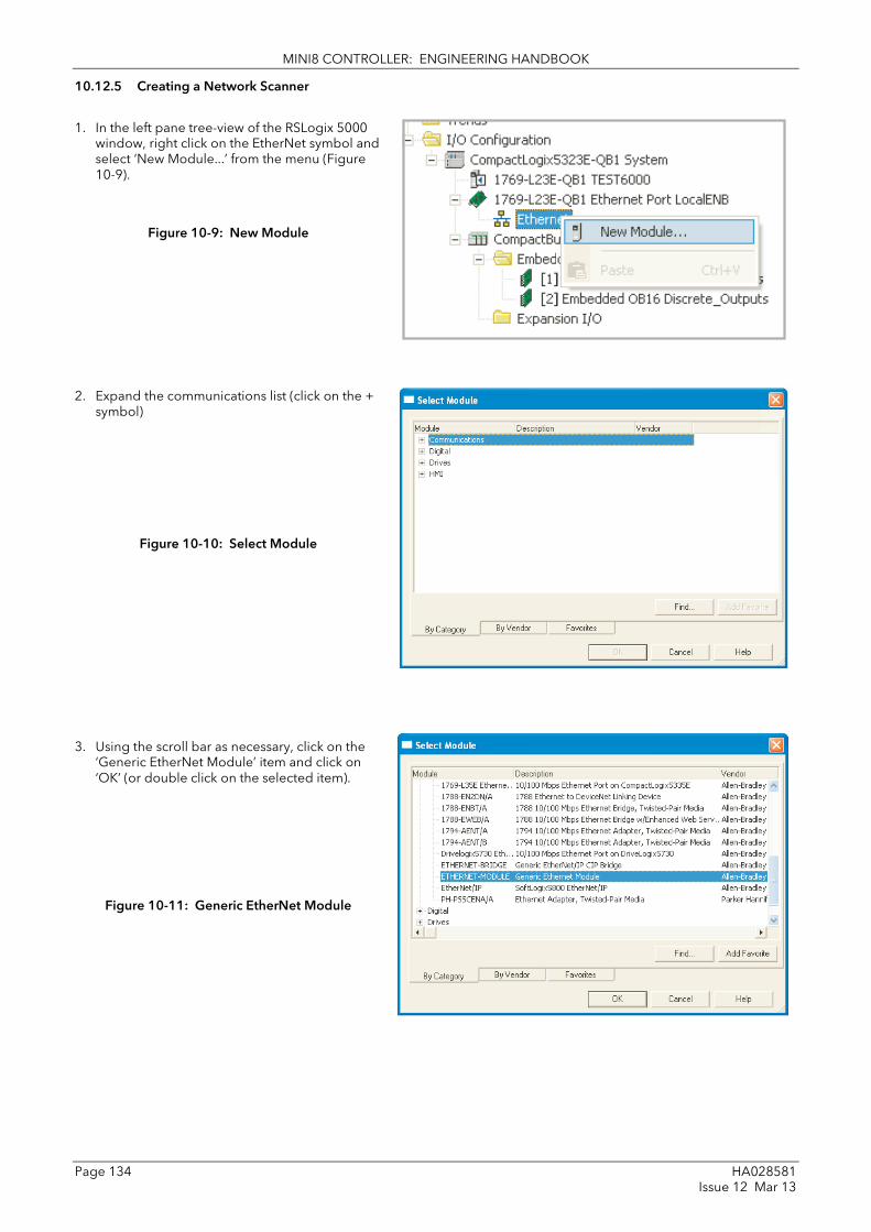
MINI8 CONTROLLER: ENGINEERING HANDBOOK
Page 134 HA028581 Issue 12 Mar 13
10.12.5 Creating a Network Scanner
1. In the left pane tree-view of the RSLogix 5000 window, right click on the EtherNet symbol and select ‘New Module...’ from the menu (Figure 10-9).
Figure 10-9: New Module
2. Expand the communications list (click on the + symbol)
Figure 10-10: Select Module
3. Using the scroll bar as necessary, click on the ‘Generic EtherNet Module’ item and click on ‘OK’ (or double click on the selected item).
Figure 10-11: Generic EtherNet Module

MINI8 CONTROLLER: ENGINEERING HANDBOOK
HA028581 Page 135 Issue 12 Mar 13
3. In the New Module page that appears (Figure 10-12), enter a name for the module, and set Connection Parameter values:
Figure 10-12: New Module
Enter data for the mini8 controller as follows:-
1. Select the Comm Format first as: Data – INT – the Size is then defined as a 16-bit number. Note, this box is greyed when once the module has been established.
2. Address/Host name: The IP address of the mini8 controller (this can be found in iTools, Comms menu IP address).
3. Input: 100; Size: 40 (see Note 1)
4. Output: 112; Size: 24 (see Note 1)
(Size MUST match the Input Output definitions shown in iTools Comms menu)
5. Configuration: 103; Size 0 (see Note 1)
6. Tick (click on) the ‘Open Module Properties’ checkbox if it is not already ticked.
7. Click on ‘OK”
The ‘Module Properties’ window is now shown (Figure 10-13).
Set the Requested Packet Interval (RPI) to 1000 (1 second) and click ‘OK’.
See also section 10.11.6.
Figure 10-13: Module Properties
At this point the PLC is configured.
It is then necessary to create or load a pre-determined application for the mini8 controller application using iTools, go to section 10.12.6.

MINI8 CONTROLLER: ENGINEERING HANDBOOK
Page 136 HA028581 Issue 12 Mar 13
NOTE 1:-
Figure 10-14: EZ-EDS
This note shows how the above values can be found using the EZ-EDS tool, as follows:-.
The Connection Parameters are fixed for a Mini8 controller, but may be found from the EDS file relevant to the Mini8 controller in use. The figure below shows an example of the EDS file for the Input Assembly Instance. Click Create/Decode Path button to show the ‘Path’ pop up window. The instance is shown in Hex as 64. Note: in the New Module selection (Figure 10-2) it is entered in decimal as 100.
A similar page is available for the Output Assembly Instance.

MINI8 CONTROLLER: ENGINEERING HANDBOOK
HA028581 Page 137 Issue 12 Mar 13
10.12.6 Create or Load a Mini8 Controller Configuration
1. Ensure an EtherNet/IP comms module is fitted and recognized by the instrument.
2. Configure the mini8 controller using iTools. In the example below the all 8 loops in the mini8 controller slave have been setup for temperature control as shown for Loop 1 in the iTools Graphical Wiring (
Figure 10-15).
Figure 10-15: Mini8 Controller Graphical Wiring

MINI8 CONTROLLER: ENGINEERING HANDBOOK
Page 138 HA028581 Issue 12 Mar 13
10.12.7 Run Mode
1. Set the PLC into either ‘Remote’ or ‘Run’ mode. This can be done using the key switch on the PLC or in the RSLogix5000 menu.
2. Set the PLC online.
At this point you may be asked to download the file if it is different
Figure 10-16: Go online

MINI8 CONTROLLER: ENGINEERING HANDBOOK
HA028581 Page 139 Issue 12 Mar 13
10.12.8 Monitor Parameters
It is possible to check that the PLC is communicating with the mini8 controller using the ‘Tags’ display to write values to the mini8 controller and to receive values from it. Once it is proved that the link is working, the pc may be disconnected from the PLC.
1. In the left pane tree-view of the RSLogix 5000 window, double click on the Controller Tags symbol.
2. Set the PLC online
3. Expand the Name list (click on the + symbol) to view parameter values. Some non zero values should appear next to input data
Figure 10-17: Monitor Inputs and Outputs via Controller Tags
10.12.9 Status Indicators
The status indicators at the top left corner of the RSLogix 5000 Page show the status of the link between the pc and the PLC.
Figure 10-18: Status Indicators

MINI8 CONTROLLER: ENGINEERING HANDBOOK
Page 140 HA028581 Issue 12 Mar 13
10.12.10 Mini8 Controller on an Ethernet/Ip Network
To obtain a graphical representation of the network configuration (if required) proceed as follows:
1. Start the RSNetWorx for EtherNet/IP program (from ‘Start/All programs/... /RSNetWorx for EtherNet/IP).
2. In the ‘Tools’ menu select EDS Wizard.
3. Locate the EDS file in the Hardware list. In the Vendor list select InvensysEurothermMini8 and register the mini8 controller EDS file and icon. The EDS file is available from Eurotherm. After successful registration, an entry will appear in the Generic Device list.
4. Drag and Drop devices from the registered Hardware list to create your network. Figure 10-19 shows an example of two mini8 controllers on a network together with a nanodac controller.
Figure 10-19: Example of Eurotherm Products on an EtherNet/IP Network
Implicit (Cyclic) Messaging
Using the RSLogix 5000, the user can write a Ladder program to read (get) and write (set) Implicit (Cyclic) messages between the PLC master and mini8 controller slave.
Expilict (Acyclic) Messaging
Using the RSNetWorx for EtherNet/IP, in the 'Device' menu, select Class Instance Editor, to read (get) and write (set) Explicit (Acyclic) messages to the mini8 controller. The target controller MUST be selected.

MINI8 CONTROLLER: ENGINEERING HANDBOOK
HA028581 Page 141 Issue 12 Mar 13
10.12.11 TROUBLESHOOTING
1. Ensure Instruments are Powered On and Online and the PLC is set to RUN mode.
2. Ensure no error Indicators are active on instrument(s)
3. Ensure an EtherNet/IP comms module is fitted and recognized by the instrument
4. Ensure all instruments have unique EtherNet/IP addresses.
5. Ensure subnet Mask is not prohibiting connections.
6. Ensure Input and Output Size of EtherNet Module match exactly the Input and output Definitions (see Figure 10-12 New Module).
7. Ensure Assembly Instance values are supported by the mini8 controller (see Figure 10-12 New Module)
8. Ensure EtherNet cables are not disconnected or damaged.
9. Use PING command from a PC with a similar EtherNet/IP address to verify instrument is responding.
10. Ensure any user program running on PLC is not performing illegal operations.

MINI8 CONTROLLER: ENGINEERING HANDBOOK
Page 142 HA028581 Issue 12 Mar 13
11. Chapter 11 Counters, Timers, Totalisers, RT Clock
A series of function blocks are available which are based on time/date information. These may be used as part of the control process.
11.1 Counters Up to two counters are available. They provide a synchronous edge triggered event counter.
Figure 11-1: Counter Function Block
When configured as an Up counter, Clock events increment Count until reaching the Target. On reaching Target RippleCarry is set true. At the next clock pulse, Count returns to zero. Overflow is latched true and RippleCarry is returned false.
When configured as a down counter, Clock events decrement Count until it reaches zero. On reaching zero RippleCarry is set true. At the next clock pulse, Count returns to the Target count. Overflow is latched true and RippleCarry is reset false
Counter blocks can be cascaded as shown in the diagram below
Figure 11-2: Cascading Counters
The RippleCarry output of one counter acts as an enabling input for the next counter. In this respect the next counter in sequence can only detect a clock edge if it was enabled on the previous clock edge. This means that the Carry output from a counter must lead its Overflow output by one clock cycle. The Carry output is, therefore, called a RippleCarry as it is NOT generated on an Overflow (i.e. Count > Target) but rather when the count reaches the target (i.e. Count = Target). The timing diagram below illustrates the principle for the Up Counter.
Figure 11-3: Timing Diagram for an Up Counter
Clock
Count = Target -1
Count = Target Count = 0
RippleCarry
Overflow
Direction
Enable
Clock
Target
Reset
Clear Overflow
Count
Overflow
RippleCarry
Counter Function
Block
Count
Overflow
RippleCarry
Direction
Enable
Clock
Target
Reset
Clear Overflow
Counter Function Block 1
Direction
Enable
Clock
Target
Reset
Clear Overflow
Counter Function Block 1
Count
Overflow
RippleCarry

MINI8 CONTROLLER: ENGINEERING HANDBOOK
HA028581 Page 143 Issue 12 Mar 13
11.1.1 Counter Parameters
Folder - Counter Sub-folders: 1 to 2
Name
Parameter Description Value
Default Access Level
Enable Counter enable. Counter 1 or 2 is enabled in the Instrument Options folder but they can also be turned on or off in this list
Yes
No
Enabled Disabled
No Oper
Direction Defines count up or count down. This is not intended for dynamic operation (i.e. subject to change during counting). It can only be set in configuration level.
Up Down
Up counter Down counter
Up Conf
Ripple Carry Ripple carry to act as an enabling input to the next counter. It is turned On when the counter reaches the target set
Off R/O
Overflow Overflow flag is turned on when the counter reaches zero
R/O
Clock Tick period to increment or decrement the count. This is normally wired to an input source such as a digital input.
0 1
No clock input Clock input present
0 R/O if wired
Target Level to which the counter is aiming
0 to 99999 9999 Oper
Count Counts each time a clock input occurs until the target is reached.
0 to 99999 R/O
Reset Resets the counter No Yes
Not in reset Reset
No Oper
Clear Overflow
Clear overflow flag No Yes
Not cleared Cleared
No Oper

MINI8 CONTROLLER: ENGINEERING HANDBOOK
Page 144 HA028581 Issue 12 Mar 13
11.2 Timers
Up to eight timers can be configured. Each one can be configured to a different type and can operate independently of one another.
11.2.1 Timer Types Each timer block can be configured to operate in four different modes. These modes are explained below
11.2.2 On Pulse Timer Mode This timer is used to generate a fixed length pulse from an edge trigger.
• The output is set to On when the input changes from Off to On.
• The output remains On until the time has elapsed
• If the ‘Trigger’ input parameter recurs while the Output is On, the Elapsed Time will reset to zero and the Output will remain On
• The triggered variable will follow the state of the output
The diagram illustrates the behaviour of the timer under different input conditions.
Figure 11-4: On Pulse Timer Under Different Input Conditions
Input
Output
Elapsed Time
Triggered
Time Time
Input
Output
Elapsed Time
Triggered
Time
Input Interval > Time

MINI8 CONTROLLER: ENGINEERING HANDBOOK
HA028581 Page 145 Issue 12 Mar 13
11.2.3 On Delay Timer Mode
This timer provides a delay between the trigger event and the Timer output. If the input pulse is less than the set delay time there is no output pulse.
• The Output is set to Off when the Input changes from Off to On.
• The Output remains Off until the Time has elapsed.
• If the Input returns to Off before the time has elapsed, the Timer will cease and there will be no output.
• If the Input remains on until the Time has elapsed, the Output will be set to On.
• The Output will remain On until the Input is cleared to Off.
• The Triggered variable will be set to On by the Input changing from Off to On. It will remain On until both the Time has elapsed and the Output has reset to Off.
The diagram illustrates the behaviour of the timer under different input conditions.
Figure 11-5: On Delay Timer under Different Input Conditions
This type of timer is used to ensure that the output is not set unless the input has been valid for a pre-determined period of time, thus acting as a kind of input filter.
Input
Output
Elapsed Time
Triggered
Time
Time When the elapsed time is less than the set time no Output is generated

MINI8 CONTROLLER: ENGINEERING HANDBOOK
Page 146 HA028581 Issue 12 Mar 13
11.2.4 One Shot Timer Mode
This timer behaves like a simple oven timer.
• When the Time is edited to a non-zero value the Output is set to On
• The Time value is decremented until it reaches zero. The Output is then cleared to Off
• The Time value can be edited at any point to increase or decrease the duration of the On time
• Once set to zero, the Time is not reset to a previous value, it must be edited by the operator to start the next On-Time
• The Input is used to gate the Output. If the Input is set, the time will count down to zero. If the Input is cleared to Off, then the Time will hold and the Output will switch Off until the Input is next set.
Note: since the Input is a digital wire, it is possible for the operator to NOT wire it, and set the Input value to On which permanently enables the timer.
• The Triggered variable will be set to On as soon as the Time is edited. It will reset when the Output is cleared to Off.
The behaviour of the timer under different input conditions is shown below.
Figure 11-6: One Shot Timer
Input
Output A D C B
Time Edited A+B+C+D = Time
This diagram shows how the Input can be used to gate the Timer as a type of hold
Input
Output
Elapsed Time
Triggered
Time
Time Edited
Time
Time Edited
A B
A+B = Time

MINI8 CONTROLLER: ENGINEERING HANDBOOK
HA028581 Page 147 Issue 12 Mar 13
11.2.5 Minimum On Timer or Compressor Mode
This type of timer may also be known as an ‘Off Delay’ function where the output goes ‘on’ when the input goes active and remains on for a specified period after the input goes inactive.
It may be used, for example, to ensure that a compressor is not cycled excessively.
• The output will be set to On when the Input changes from Off to On.
• When the Input changes from On to Off, the elapsed time will start incrementing towards the set Time.
• The Output will remain On until the elapsed time has reached the set Time. The Output will then switch Off.
• If the Input signal returns to On while the Output is On, the elapsed time will reset to 0, ready to begin incrementing when the Input switches Off.
• The Triggered variable will be set while the elapsed time is >0. It will indicate that the timer is counting.
The diagram illustrates the behaviour of the timer under different input conditions.
Figure 11-7: Minimum On Timer Under Different Input Conditions
Input
Output
Elapsed Time
Triggered
Time Time

MINI8 CONTROLLER: ENGINEERING HANDBOOK
Page 148 HA028581 Issue 12 Mar 13
11.2.6 Timer Parameters
Folder – Timer Sub-folders: 1 to 4
Name
Parameter Description Value
Default Access Level
Type Timer type Off Timer not configured Off Conf On Pulse Generates a fixed length pulse from
an edge trigger Off Delay Provides a delay between input
trigger event and timer putput One Shot
Simple oven timer which reduces to zero before switching off
Min-On Ti
Compressor timer guaranteeing that the output remains ON for a time after the input signal has been removed
Time Duration of the timer. For re-trigger timers this value is entered once and copied to the time remaining parameter whenever the timer starts. For pulse timers the time value itself is decremented.
0:00.0 to 99:59:59 0:00.0 Oper
Elapsed Time
Timer elapsed time 0:00.0 to 99:59:59 R/O
In Trigger/Gate input. Turn On to start timing
Off On
Off Start timing
Off Oper
Out Timer output Off On
Output off Timer has timed out
R/O
Triggered Timer triggered (timing). This is a status output to indicate that the timers input has been detected
Off On
Not timing Timer timing
R/O
The above table is repeated for Timers 2 to 4.

MINI8 CONTROLLER: ENGINEERING HANDBOOK
HA028581 Page 149 Issue 12 Mar 13
11.3 Totalisers
There are two totaliser function blocks which are used to measure the total quantity of a measurement integrated over time. A totaliser can, by soft wiring, be connected to any measured value. The outputs from the totaliser are its integrated value and an alarm state. The user may set a setpoint which causes the alarm to activate once the integration exceeds the setpoint.
The totaliser has the following attributes:-
1. Run/Hold/Reset In Run the totaliser will integrate its input and continuously test against an alarm setpoint.
In Hold the totaliser will stop integrating its input but will continue to test for alarm conditions.
In Reset the totaliser will be zeroed, and alarms will be reset.
2. Alarm Setpoint If the setpoint is a positive number, the alarm will activate when the total is greater than the setpoint.
If the setpoint is a negative number, the alarm will activate when the total is lower (more negative) than the setpoint.
If the totaliser alarm setpoint is set to 0.0, the alarm will be off. It will not detect values above or below.
The alarm output is a single state output. It may be cleared by resetting the totaliser, or by changing the alarm setpoint.
3. Limits The total is limited to a maximum of 9,999,999,999 and a minimum of -9,999,999,999.
4. Resolution The totaliser ensures that resolution is maintained when integrating small values onto a large total.

MINI8 CONTROLLER: ENGINEERING HANDBOOK
Page 150 HA028581 Issue 12 Mar 13
11.3.1 Totaliser Parameters
Folder – Total Sub-Folders: 1 to 2
Name
Parameter Description Value
Default Access Level
TotalOut The totalised value ±9,999,999,999 R/O
In The value to be totalised
-9999.9 to 9999.9. Note:- the totaliser stops accumulating if the input is ‘Bad’.
Oper
Units Totaliser units None AbsTemp V, mV, A, mA, PH, mmHg, psi, Bar, mBar, %RH, %, mmWG, inWG, inWW, Ohms, PSIG, %O2, PPM, %CO2, %CP, %/sec, RelTemp mBar/Pa/T sec, min, hrs,
Conf
Resolution Totaliser resolution XXXXX XXXX.X XXX.XX XX.XXX X.XXXX
XXXXX Conf
Alarm SP Sets the totalised value at which an alarm will occur
±9,999,999,999 Oper
AlarmOut This is a read only value which indicates the alarm output On or Off. The totalised value can be a positive number or a negative number. If the number is positive the alarm occurs when Total > + Alarm Setpoint If the number is negative the alarm occurs when Total > - Alarm Setpoint
Off On
Alarm inactive Alarm output active
Off Oper
Run Runs the totaliser No Yes
Totaliser not running Select Yes to run the totaliser
No Oper
Hold Holds the totaliser at its current value Note: The Run & Hold parameters are designed to be wired to (for example) digital inputs. Run must be ‘on’ and Hold must be ‘off’ for the totaliser to operate.
No Yes
Totaliser not in hold Hold totaliser
No Oper
Reset Resets the totaliser No Yes
Totaliser not in reset Totaliser in reset
No Oper

MINI8 CONTROLLER: ENGINEERING HANDBOOK
HA028581 Page 151 Issue 12 Mar 13
11.4 Real Time Clock
A real time clock (day of week and time only) is used to provide a daily and weekly scheduling facility and provides two corresponding outputs. The configuration for an output is an On-Day and an On-Time and an Off-Day and an Off-Time.
The Real Time Clock also provides the time stamping in the AlarmLog (Section 8.8).
The day options supported are:-
Day Option Description
Never Disables the output feature
Monday Output will only be available on a Monday
Tuesday Output will only be available on a Tuesday
Wednesday Output will only be available on a Wednesday
Thursday Output will only be available on a Thursday
Friday Output will only be available on a Friday
Saturday Output will only be available on a Saturday
Sunday Output will only be available on a Sunday
Mon-Fri Output will only be available between Monday to Friday
Mon-Sat Output will only be available on between Monday to Saturday
Sat-Sun Output will only be available on between Saturday to Sunday
Everyday Output always available
For example, it is possible to configure an output to be activated at 07:30 on Monday and deactivated at 17:15 on Friday
The output from the Real Time Clock outputs may be used to place the instrument in standby or to sequence a batch process.
The Real Time Clock function will set/clear the outputs only at the configured time. Therefore it is possible to override the outputs manually, by editing the output to On/Off between output activations.
The Real Time Clock does not display date or year.
11.4.1 Real Time Clock Parameters
Folder – RTClock Sub Folders: None
Name Parameter Description Value Default Access Level
Mode This parameter can be used to set the clock
Running Normal operation Stopped Oper
Edit Allows the clock to be set
Stopped Clock stopped (saves battery life)
Day Displays the day or allows the day to be set when in Edit mode
Monday to Sunday Oper
Time Displays the time or allows the time to be set when in Edit mode
00:00:00 to 23:59:59 Oper
On Day1 On Day2
Days when output 1 and 2 are activated
See table above Oper
On Time1 On Time2
Time of day when output 1 and 2 are activated
00:00:00 to 23:59:59 Oper
Off Day1 Off Day2
Days when output 1 and 2 are de-activated
See table above Oper
Off Time1 Off Time2
Time of day when output 1 and 2 are de-activated
00:00:00 to 23:59:59 Oper
Out1 Out2
Output 1 and 2 Off On
Output not activated Output activated
Oper

MINI8 CONTROLLER: ENGINEERING HANDBOOK
Page 152 HA028581 Issue 12 Mar 13
12. Chapter 12 Applications
12.1 Humidity
12.1.1 Overview Humidity (and altitude) control is a standard feature of the Mini8 controller. In these applications the controller may be configured to generate a setpoint profile (see Section 0 ‘Setpoint Programmer’).
Also the controller may be configured to measure humidity using either the traditional Wet/Dry bulb method or it may be interfaced to a solid state sensor.
The controller output may be configured to turn a refrigeration compressor on and off, operate a bypass valve, and possibly operate two stages of heating and/or cooling
12.1.2 Temperature Control of an Environmental Chamber The temperature of an environmental chamber is controlled as a single loop with two control outputs. The heating output time proportions electric heaters, usually via a solid state relay. The cooling output operates a refrigerant valve which introduces cooling into the chamber. The controller automatically calculates when heating or cooling is required.
12.1.3 Humidity Control of an Environmental Chamber Humidity in a chamber is controlled by adding or removing water vapour. Like the temperature control loop two control outputs are required, i.e. Humidify and Dehumidify.
To humidify the chamber water vapour may be added by a boiler, an evaporating pan or by direct injection of atomised water.
If a boiler is being used adding steam increases the humidity level. The humidify output from the controller regulates the amount of steam from the boiler that is allowed into the chamber.
An evaporating pan is a pan of water warmed by a heater. The humidify output from the controller humidity regulates the temperature of the water.
An atomisation system uses compressed air to spray water vapour directly into the chamber. The humidify output of the controller turns on or off a solenoid valve.
Dehumidification may be accomplished by using the same compressor used for cooling the chamber. The dehumidify output from the controller may control a separate control valve connected to a set of heat exchanger coils.

MINI8 CONTROLLER: ENGINEERING HANDBOOK
HA028581 Page 153 Issue 12 Mar 13
12.1.4 Humidity Parameters
List Folder – Humidity Sub-folder: None
Name
Parameter Description Value
Default Access Level
Resolution Resolution of the relative humidity
XXXXX XXXX.X XXX.XX XX.XXX X.XXXX
Conf
Psychro Const
The psychrometric constant at a given pressure (6.66E-4 at standard atmospheric pressure). The value is dependent on the speed of air-flow across the wet bulb, and hence the rate of evaporation. 6.66E-4 is for the ASSMANN ventilated Psychrometer.
0.0 to 10.0 6.66 Oper
Pressure Atmospheric Pressure 0.0 to 2000.0 1013.0 mbar
Oper
WetTemp Wet Bulb Temperature Range units
WetOffset Wet bulb temperature offset -100.0 to 100.0 0.0 Oper
DryTemp Dry Bulb Temperature Range units
RelHumid Relative Humidity is the ratio of actual water vapour pressure (AVP) to the saturated water vapour pressure (SVP) at a particular temperature and pressure
0.0 to 100.0 100 R/O
DewPoint The dew point is the temperature to which air would need to cool (at constant pressure and water vapour content) in order to reach saturation
-999.9 to 999.9 R/O
Sbrk Indicates that one of the probes is broken.
No Yes
No sensor break detection Sensor break detection enabled
Conf

MINI8 CONTROLLER: ENGINEERING HANDBOOK
Page 154 HA028581 Issue 12 Mar 13
12.2 Zirconia (Carbon Potential) Control A Mini8 Controller has a Zirconia function block which may be used to control Carbon potential. The controller is often a programmer which generates carbon potential profiles. In this section it is assumed that a programmer is used.
Calculation of PV: The Process Variable can be Carbon Potential, Dewpoint or Oxygen concentration. The PV is derived from the probe temperature input, the probe mV input and remote gas reference input values. Various probe makes are supported. In the Mini8 Controller Carbon Potential and Dewpoint can be displayed together.
The following definitions may be useful:-
12.2.1 Temperature Control The sensor input of the temperature loop may come from the zirconia probe but it is common for a separate thermocouple to be used. The controller provides a heating output which may be connected to gas burners or thyristors to control electrical heating elements. In some applications a cooling output may also be connected to a circulation fan or exhaust damper.
12.2.2 Carbon Potential Control The zirconia probe generates a millivolt signal based on the ratio of oxygen concentrations on the reference side of the probe (outside the furnace) to the amount of oxygen in the furnace.
The controller uses the temperature and carbon potential signals to calculate the actual percentage of carbon in the furnace. This second loop generally has two outputs. One output is connected to a valve which controls the amount of an enrichment gas supplied to the furnace. The second output controls the level of dilution air.
12.2.3 Sooting Alarm In addition to other alarms which may be detected by the controller, the Mini8 Controller can trigger an alarm when the atmospheric conditions are such that carbon will be deposited as soot on all surfaces inside the furnace. The alarm may be connected to an output (e.g. relay) to initiate an external alarm.
12.2.4 Automatic Probe Cleaning
The Zirconia function block has a probe clean and recovery strategy that can be programmed to occur between batches or manually requested. At the start of the cleaning process a ‘snapshot’ of the probe mV is taken, and a short blast of compressed air is used to remove any soot and other particles that may have accumulated on the probe. A minimum and maximum cleaning time can be set by the user. If the probe mV has not recovered to within 5% of the snapshot value within the maximum recovery time set then an alarm is given. This indicates that the probe is ageing and replacement or refurbishment is due. During the cleaning and recovery cycle the PV is frozen, thereby ensuring continuous furnace operation. A flag ‘PvFrozen’ is set which can be used in an individual strategy, for example to hold the integral action during cleaning.
12.2.5 Endothermic Gas Correction A gas analyser may be used to determine the CO concentration of the endothermic gas. If a 4-20mA output is available from the analyser, it can be fed into the Mini8 Controller to automatically adjust the calculated % carbon reading. Alternatively, this value can be entered manually.
12.2.6 Clean Probe As these sensors are used in furnace environments they require regular cleaning. Cleaning (Burn Off) is performed by forcing compressed air through the probe. Cleaning can be initiated either manually or automatically using a timed period. During cleaning the PV output is frozen.
12.2.7 Probe Status After cleaning an alarm output, MinCalcT, is generated if the PV does not return to 95% of its previous value within a specified time. This indicates that the probe is deteriorating and should be replaced.

MINI8 CONTROLLER: ENGINEERING HANDBOOK
HA028581 Page 155 Issue 12 Mar 13
12.2.8 Zirconia Parameters
Folder - Zirconia Sub-folders: None
Name Parameter Description Value Default Access Level
Probe Type Configures the type of probe to be used
Drayton Accucarb SSI MacDhui %O2 LogO2 BoschO2 ZircoDew ProbeMV BoschCarb BarberC MMICarb AACC
Drayton Accucarb SSI MacDhui Oxygen Log Oxygen Bosch Oxygen Dewpoint. Probe mV Bosch Carbon Barber-Colman MMI Carbon AACC
Op
Resolution Resolution of the calculated result X X.X X.XXX X.XXX X.XXXX
X Op
Parameters shown in shaded rows below are not applicable to O2 probes
GasRef Gas reference value -9999.9 to 9999.9 20.0 Op
RemGasRef Remote gas reference value -9999.9 to 9999.9 0.0 Op
RemGasEn Enable the remote gas reference. This can be an internal value from the user interface or from an external source
0 1
Internal External
0 Op
MinCalTemp Minimum calculation temperature -99999 to 99999 720 Op
OxygenExp The exponent units of the log oxygen type calculation
Tolerance Tolerance of the sooting -9999.9 to 9999.9 1.0 Op
CleanFreq Frequency of the cleaning process 0:00:00 to 99:59:59 or 100:00 to 500:00
4:00:00 Op
CleanTime Sets the duration of the clean 0:00:00 to 99:59:59 or 100:00 to 500:00
0:00:00 Op
MinRcovTime Minimum recovery time after purging 0:00:00 to 99:59:59 or 100:00 to 500:00
0:00:00 Op
MaxRcovTime Maximum recovery time after purging 0:00:00 to 99:59:59 or 100:00 to 500:00
0:10:00 Op
TempInput Zirconia probe temperature input value Temp range Op
TempOffset Sets a temperature offset for the probe -99999 to 99999 0 Op
ProbeInput Zirconia probe mV input Op
ProbeOffset Zirconia probe mV offset -99999 to 99999 0 Op
Oxygen Calculated oxygen 0
CarbonPot Calculated carbon potential 0 R/O
DewPoint Zirconia control process value The O2 or dew point value derived from temperature and remote gas reference inputs
0 R/O
SootAlm Probe sooting alarm output No Yes
No alarm output In alarm
No R/O
ProbeFault Probe fault No Yes
No Op
PvFrozen This is a Boolean which freezes the PV during a purging cycle. It may have been wired, for example, to disable control output during purging
No Yes
No R/O
CleanValve Enable the clean valve. No Yes
No R/O

MINI8 CONTROLLER: ENGINEERING HANDBOOK
Page 156 HA028581 Issue 12 Mar 13
Folder - Zirconia Sub-folders: None
Name Parameter Description Value Default Access Level
CleanState The burn off state of the zirconia probe Waiting Cleaning Recovering
R/O
CleanProbe Enable clean probe. This may be wired to initiate automatically or if un-wired can be set by the user
No Yes
Do not clean probe Initiate probe clean
No Op
Time2Clean Time to next clean. 0:00:00 to 99:59:59 or 100:00 to 500:00
0 R/O
ProbeStatus Indicates the status of the probe. OK Normal working R/O
mVSbr Probe input in sensor break
TempSbr Temperature input in sensor break
MinCalcT Probe deteriorating

MINI8 CONTROLLER: ENGINEERING HANDBOOK
HA028581 Page 157 Issue 12 Mar 13
13. Chapter 13 Input Monitor
13.1 Description There are two Input monitors. Each input monitor may be wired to any variable in the controller. It then provides three functions:-
1. Maximum detect
2. Minimum detect
3. Time above threshold
13.1.1 Maximum Detect This function continuously monitors the input value. If the value is higher than the previously recorded maximum, it becomes the new maximum.
This value is retained following a power fail.
13.1.2 Minimum Detect This function continuously monitors the input value. If the value is lower than the previously recorded minimum, it becomes the new minimum.
This value is retained following a power fail.
13.1.3 Time Above Threshold This function increments a timer whenever the input is above a threshold value. If the timer exceeds 24 hours per day, a counter is incremented. The maximum number of days is limited to 255. A time alarm can be set on the timer so that once the input has been above a threshold for a period, an alarm output is given.
Applications include:-
• Service interval alarms. This sets an output when the system has been running for a number of days (up to 255 days)
• Material stress alarms - if the process cannot tolerate being above a level for a period. This is a style of ‘policeman’ for processes where the high operating point degrades the life of the machine.
• In internal wiring applications in the controller

MINI8 CONTROLLER: ENGINEERING HANDBOOK
Page 158 HA028581 Issue 12 Mar 13
13.2 Input Monitor Parameters
Folder - IPMonitor Sub-Folders: 1 or 2
Name Parameter Description Value Default Access Level
In The input value to be monitored
May be wired to an input source. The range will depend on the source
Oper R/O if wired
Max The maximum measured value recorded since the last reset
As above R/O
Min The minimum measured value recorded since the last reset
As above R/O
Threshold The input timer accumulates the time the input PV spends above this trigger value.
As above Oper
Days Above Accumulated days the input has spent above threshold since the last reset.
Days is an integer count of the 24 hour periods only. The Days value should be combined with the Time value to make the total time above threshold.
R/O
Time Above Accumulated time above the ‘Threshold’ since last reset.
The time value accumulates from 00:00.0 to 23:59.9. Overflows are added to the days value
R/O
AlarmDays Days threshold for the monitors time alarm. Used in combination with the Alarm Time parameter. The ‘Out’ is set to true if the inputs accumulated time above threshold is higher than the timer high parameters.
0 to 255 0 Oper
AlarmTime Time threshold for the monitors time alarm. Used in combination with the Alarm Days parameter. The ‘Out’ is set to true if the inputs accumulated time above threshold is higher than the timer high parameters.
0:00.0 to 99:59:59 0:00.0 Oper
Out Set true if the accumulated time that the input spends above the trigger value is higher than the alarm threshold.
Off On
Normal operation time above setpoint exceeded
R/O
Reset Resets the Max and Min values and resets the time above threshold to zero.
No Yes
Normal operation Reset values
No Oper
In Status Monitors the status of the input
Good Bad
Normal operation The input may be incorrectly wired
R/O Oper

MINI8 CONTROLLER: ENGINEERING HANDBOOK
HA028581 Page 159 Issue 12 Mar 13
14. Chapter 14 Logic and Maths Operators.
14.1 Logic Operators Logic Operators allow the controller to perform logical calculations on two input values. These values can be sourced from any available parameter including Analogue Values, User Values and Digital Values.
The parameters to use, the type of calculation to be performed, input value inversion and ‘fallback’ value are determined in Configuration level.
There are 24 separate calculations – they do not have to be in sequence. When logic operators are enabled a Folder ‘Lgc2’ exists where the 2 denotes two input logic operators.
Figure 14-1: 2 Input Logic Operators
Logic Operators are found under the folder ‘Lgc2’. Note that the logic operators can also be enable by dragging a block onto the graphical wiring screen in iTools.
14.1.1 Logic 8
Logic 8 operators can perform logic calculations on up to eight inputs. The calculations are limited to AND,OR,XOR. Up to two 8 input operators can be enabled. The folder is labelled ‘Lgc8’ to denote eight input logic operators.
Figure 14-2: 8 Input Logic Operators
Logic input 1
Logic input 2
Output Value (result of calculation)
Logic operator (Oper)
Invert
Invert
Logic input 1
Logic input 2
Output Value (result of calculation)
Logic operator (Oper)
Invert
Invert
Logic input 3
Logic input 4
Invert
Invert
Logic input 5
Logic input 6
Invert
Invert
Logic input 7
Logic input 8
Invert
Invert
Invert

MINI8 CONTROLLER: ENGINEERING HANDBOOK
Page 160 HA028581 Issue 12 Mar 13
14.1.2 2 input Logic Operations
The following calculations can be performed:
Oper Operator description Input 1 Input 2 Output Invert = None
0: OFF The selected logic operator is turned off
1: AND The output result is ON when both Input 1 and Input 2 are ON
0 1 0 1
0 0 1 1
Off Off Off On
2: OR The output result is ON when either Input 1 or Input 2 is ON
0 1 0 1
0 0 1 1
Off On On On
3: XOR Exclusive OR. The output result is true when one and only one input is ON. If both inputs are ON the output is OFF.
0 1 0 1
0 0 1 1
Off On On Off
4: Latch Input 1 sets the latch, Input 2 resets the latch.
0 1 0 1
0 0 1 1
5: Equal (==) The output result is ON when Input 1 = Input 2
0 1 0 1
0 0 1 1
On Off Off On
6: Not equal (<>)
The output result is ON when Input 1 does not equal Input 2
0 1 0 1
0 0 1 1
Off On On Off
7: Greater than (>)
The output result is ON when Input 1 > Input 2
0 1 0 1
0 0 1 1
Off On Off Off
8: Less than (<) The output result is ON when Input 1 < Input 2
0 1 0 1
0 0 1 1
Off Off On Off
9: Equal to or Greater than (=>)
The output result is ON when Input 1 > Input 2
0 1 0 1
0 0 1 1
On On Off On
10: Less than or Equal to (<=)
The output result is ON when Input 1 < Input 2
0 1 0 1
0 0 1 1
On Off On On
Note 1: The numerical value is the value of the enumeration
Note 2: For options 1 to 4 an input value of less than 0.5 is considered false and greater than or equal to 0.5 as true.
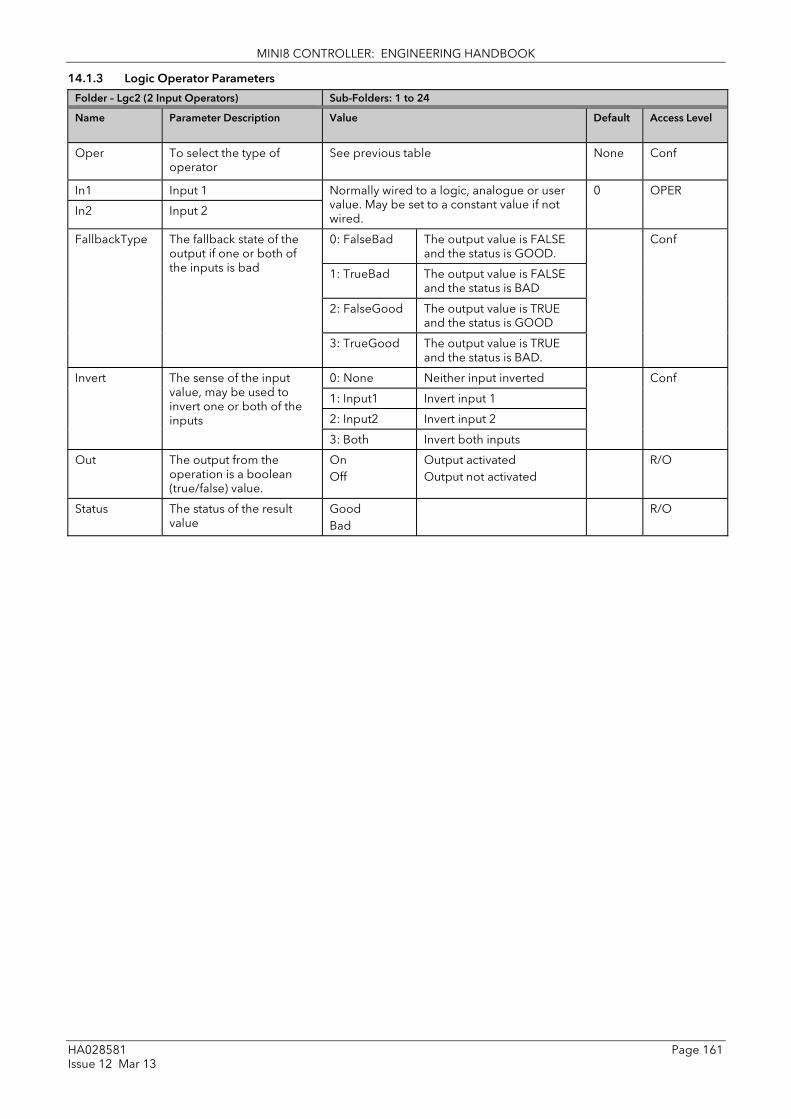
MINI8 CONTROLLER: ENGINEERING HANDBOOK
HA028581 Page 161 Issue 12 Mar 13
14.1.3 Logic Operator Parameters
Folder – Lgc2 (2 Input Operators) Sub-Folders: 1 to 24
Name
Parameter Description Value
Default Access Level
Oper To select the type of operator
See previous table None Conf
In1 Input 1 Normally wired to a logic, analogue or user value. May be set to a constant value if not wired.
0 OPER
In2 Input 2
FallbackType The fallback state of the output if one or both of the inputs is bad
0: FalseBad The output value is FALSE and the status is GOOD.
Conf
1: TrueBad The output value is FALSE and the status is BAD
2: FalseGood The output value is TRUE and the status is GOOD
3: TrueGood The output value is TRUE and the status is BAD.
Invert The sense of the input value, may be used to invert one or both of the inputs
0: None Neither input inverted Conf 1: Input1 Invert input 1
2: Input2 Invert input 2
3: Both Invert both inputs
Out The output from the operation is a boolean (true/false) value.
On Off
Output activated Output not activated
R/O
Status The status of the result value
Good Bad
R/O

MINI8 CONTROLLER: ENGINEERING HANDBOOK
Page 162 HA028581 Issue 12 Mar 13
14.2 Eight Input Logic Operators The eight input logic operator may be used to perform the following operations on eight inputs.
Oper Operator description
0: OFF The selected logic operator is turned off
1: AND The output result is ON when ALL eight inputs are ON
2: OR The output result is ON when one or more of the 8 inputs are ON
3: XOR Exclusive OR – the output is true if an odd number of inputs are true. (In1 ⊕ In2) ⊕ (In3 ⊕ In4) ⊕ (In5 ⊕ In6) ⊕ (In7 ⊕ In8)
Eight Input Logic Operator Parameters
Folder – Lgc8 (8 Input Operators) Sub-Folders: 1 to 4
Name Parameter Description Value Default Access Level
Oper To select the type of operator
0: OFF 1: AND 2: OR 3: XOR
Operator turned off Output ON when all inputs are ON Output ON when one input is ON Exclusive OR
OFF Conf
NumIn This parameter is used to configure the number of inputs for the operation
1 to 8 2 Conf
InInvert Used to invert selected inputs prior to operation. This is a status word with one bit per input, the left hand bit inverts input 1.
The invert parameter is interpreted as a bitfield where: 1 (0x1) - input 1 2 (0x2) - input 2 4 (0x4) - input 3 8 (0x8) - input 4 16 (0x10) - input 5 32 (0x20) - input 6 64 (0x40)- input 7
128 (0x80)- input 8 (e.g. 255 = all eight)
0 Oper
Out Invert Invert the output No Yes
Output not inverted Output inverted
No Oper
In1 to In8 Input state 1 to 8 Normally wired to a logic, analogue or user value. When wired to a floating point, values less than or equal to –0.5 or greater than or equal to 1.5 will be rejected (e.g. the value of the lgc8 block will not change). Values between –0.5 and 1.5 will be interpreted as ON when greater than or equal to 0.5 and OFF when less than 0.5. May be set to a constant value if not wired.
Off Oper
Out Output result of the operator
On Off
Output activated Output not activated
R/O

MINI8 CONTROLLER: ENGINEERING HANDBOOK
HA028581 Page 163 Issue 12 Mar 13
14.3 Maths Operators Maths Operators (sometimes known as Analogue Operators) allow the controller to perform mathematical operations on two input values. These values can be sourced from any available parameter including Analogue Values, User Values and Digital Values. Each input value can be scaled using a multiplying factor or scalar.
The parameters to use, the type of calculation to be performed and the acceptable limits of the calculation are determined in Configuration level. In normal operation the values of each of the scalars may be changed via communications or iTools.
There are 24 separate calculations – they do not have to be in sequence. When maths operators are enabled (in Instrument/Options folder) a Folder ‘Math2’ exists (where the 2 denotes two input maths operators).
Figure 14-3: 2 Input Math Operators
8 input multiplexers are also available and are described in section 14.5.
Output Value (result of calculation) Input 1
Input 2
Math operator Input 1 Scalar
Input 2 Scalar

MINI8 CONTROLLER: ENGINEERING HANDBOOK
Page 164 HA028581 Issue 12 Mar 13
14.3.1 Math Operations The following operations can be performed:
0: Off The selected analogue operator is turned off
1: Add The output result is the addition of Input 1 and Input 2
2: Subtract (Sub) The output result is the difference between Input 1 and Input 2 where Input 1 > Input 2
3: Multiply (Mul) The output result is the Input 1 multiplied by Input 2
4: Divide (Div) The output result is Input 1 divided by Input 2
5: Absolute Difference (AbsDif)
The output result is the absolute difference between Input 1 and 2
6: Select Max (SelMax) The output result is the maximum of Input 1 and Input 2
7: Select Min (SelMin) The output result is the minimum of Input 1 and Input 2
8: Hot Swap (HotSwp) Input 1 appears at the output provided input 1 is ‘good’. If input 1 is ‘bad’ then input 2 value will appear at the output. An example of a bad input occurs during a sensor break condition.
9: Sample and Hold (SmpHld)
Normally input 1 will be an analogue value and input B will be digital. The output tracks input 1 when input 2 = 1 (Sample). The output will remain at the current value when input 2 = 0 (Hold). If input 2 is an analogue value then any non zero value will be interpreted as ‘Sample’.
10: Power The output is the value at input 1 raised to the power of the value at input 2. I.e. input 1input 2
11: Square Root (Sqrt) The output result is the square root of Input 1. Input 2 has no effect.
12: Log The output is the logarithm (base 10) of Input 1. Input 2 has no effect
13: Ln The output is the logarithm (base n) of Input 1. Input 2 has no effect
14: Exp The output result is the exponential of Input 1. Input 2 has no effect
15: 10 x The output result is 10 raised to the power of Input 1 value. I.e. 10input 1. Input 2 has no effect
51: Select Select input is used to control which Analogue Input is switched to the output of the Analogue Operator. If the select input is true input 2 is switched through to the output. If false input 1 is switched through to the output. See example below:-
When Boolean parameters are used as inputs to analogue wiring, they will be cast to 0.0 or 1.0 as appropriate. Values <= -0.5 or >= 1.5 will not be wired. This provides a way to stop a Boolean updating. Analogue wiring (whether simple re-routing or involving calculations) will always output a real type result, whether the inputs were booleans, integers or reals.
Note: The numerical value is the value of the enumeration
If Select Input = 1, then An input 2 is selected
If Select Input = 0, then An input 1 is selected
An Op 1
Select Logic
1
An input 1
An input 2
Select input
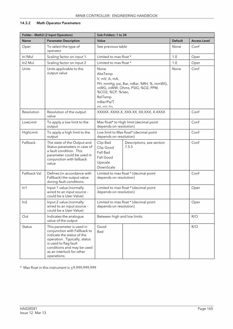
MINI8 CONTROLLER: ENGINEERING HANDBOOK
HA028581 Page 165 Issue 12 Mar 13
14.3.2 Math Operator Parameters
Folder – Math2 (2 Input Operators) Sub-Folders: 1 to 24
Name Parameter Description Value Default Access Level
Oper To select the type of operator
See previous table None Conf
In1Mul Scaling factor on input 1 Limited to max float * 1.0 Oper
In2 Mul Scaling factor on input 2 Limited to max float * 1.0 Oper
Units Units applicable to the output value
None AbsTemp V, mV, A, mA, PH, mmHg, psi, Bar, mBar, %RH, %, mmWG, inWG, inWW, Ohms, PSIG, %O2, PPM, %CO2, %CP, %/sec, RelTemp mBar/Pa/T sec, min, hrs,
None Conf
Resolution Resolution of the output value
XXXXX. XXXX.X, XXX.XX, XX.XXX, X.XXXX Conf
LowLimit To apply a low limit to the output
Max float* to High limit (decimal point depends on resolution)
Conf
HighLimit To apply a high limit to the output
Low limit to Max float* (decimal point depends on resolution)
Conf
Fallback The state of the Output and Status parameters in case of a fault condition. This parameter could be used in conjunction with fallback value
Clip Bad Clip Good Fall Bad Fall Good Upscale DownScale
Descriptions, see section 7.5.5
Conf
Fallback Val Defines (in accordance with Fallback) the output value during fault conditions.
Limited to max float * (decimal point depends on resolution)
Conf
In1 Input 1 value (normally wired to an input source – could be a User Value)
Limited to max float * (decimal point depends on resolution)
Oper
In2 Input 2 value (normally wired to an input source – could be a User Value)
Limited to max float * (decimal point depends on resolution)
Oper
Out Indicates the analogue value of the output
Between high and low limits R/O
Status This parameter is used in conjunction with Fallback to indicate the status of the operation. Typically, status is used to flag fault conditions and may be used as an interlock for other operations.
Good Bad
R/O
* Max float in this instrument is +9,999,999,999

MINI8 CONTROLLER: ENGINEERING HANDBOOK
Page 166 HA028581 Issue 12 Mar 13
14.3.3 Sample and Hold Operation The diagram below shows the operation of the sample and hold feature.
Figure 14-4: Sample and Hold
10 5 0 -5 -10
10 5 0 -5 -10
IP1
IP2
Result
True False

MINI8 CONTROLLER: ENGINEERING HANDBOOK
HA028581 Page 167 Issue 12 Mar 13
14.4 Multiple Input Operator Block The Multiple Input Operator Block simultaneously outputs the Sum, Average, Minimum and Maximum values of up to 8 valid inputs. The outputs will be clipped to user-defined limits or be replaced by a fallback value based on the selected fallback strategy.
Figure 14-5: Multi Operator Function Block
‘Num In’ determines the number of inputs made available for use. This is settable by the user and is defaulted to two. The user should be careful not to set this number to a value higher than the desired number of inputs as any unused inputs are seen as valid inputs to the block (zero value by default). Num Casc In and Casc In will always be available.
‘Input Status’ gives an indication of the status of the inputs in priority order. Casc In has the highest priority, In1 the next highest up to In8 the lowest. Should more than one input be bad then the input with the highest priority is shown as bad. When the highest priority bad status is cleared the next highest priority bad status is shown. When all inputs are OK a status of OK is shown.
‘Number of valid inputs’ provides a count of the number of inputs used to perform the calculation within the block. This is required for cascaded operation and is detailed below.
Fallback Typ
Num Valid Ins
Num Casc In
Casc In
In1
In2
In3
In4
In5
In6
In7
In8
Units
Res’n
Out Hi Limit
Out Lo Limit
Fallback Val
Sum
Min
Max
Average
Input status
MultiOper Block

MINI8 CONTROLLER: ENGINEERING HANDBOOK
Page 168 HA028581 Issue 12 Mar 13
14.4.1 Cascaded operation Multiple input operator blocks may be cascaded to allow operations on more than eight inputs (33 max for four instances of the block). shows how two blocks should be configured to find the average of more than eight inputs. If required the second block could then be cascaded to a third to provide up to eight more inputs.
Figure 14-6: Cascaded Multi Operator Function Blocks
If ‘CascIn’ is has Good status, and ‘NumCascIn’ is not equal to zero we can assume that the block is in cascade and these values are used for calculations within the block, and the value given by ‘NumCascIn’ is added to ‘NumValidIns’. When in cascade the sum, min, max and average outputs treat Casc In as an additional input to the block. For example if Casc In is greater than any number on the rest of the inputs then its value will be output as the max.
14.4.2 Fallback Strategy The user is able to select the fallback strategy during config. The options are:-
Clip Good The status of the outputs is always good
If an output is out of range then it is clipped to limits
If all inputs are bad, all outputs = 0 (Or clipped to limits if 0 is not within the output range)
Clip Bad The status of all outputs is bad if one or more of the inputs are bad
If an output is out of range then it is clipped to limits and the status of that output is set to bad
If all inputs are bad, all outputs = 0 and all status’ are set to bad (Or clipped to limits if 0 is not within the output range)
Fall Good The status of the outputs is always good
If an output is out of range then it is set to the fallback value
If all inputs are bad, all outputs = fallback value
Fall Bad The status of all outputs is bad if one or more of the inputs are bad
If an output is out of range then it is set to the fallback value and the status is set to bad
If all inputs are bad, all outputs are set to the fallback value and all statuses are set to bad
NumCascIn
Casc In
In1
In2
MultiOper NumValid
Sum
Min
Max
Average
Input status
NumCascIn
Casc In
In1
In2
MultiOper NumValid Ins
Sum
Min
Max
Average
Input status

MINI8 CONTROLLER: ENGINEERING HANDBOOK
HA028581 Page 169 Issue 12 Mar 13
14.4.3 Multiple Input Operator Block Parameters
Folder – MultiOper (Multi Operator) Sub-folders: 1 to 4
Name
Parameter Description Value
Default Access Level
NumIn Number of inputs selected to use.
2 to 8 2 Config
CascNumIn Number of cascaded inputs from the previous block
0 to 255 0 R/O
CascIn The cascaded input from a previous block
-99999 to 99999 (decimal point depends on Resolution)
0 R/O
In 1 to In 8 Input 1 -99999 to 99999 (decimal point depends on Resolution)
0 R/O
Units Selected units for the I/O Unit8 (nvol) None Config
Resolution Selected resolution of the Outputs
X to X.XXX X Config
OutHi Limit Upper limit of the outputs. -99999 to 99999 (decimal point depends on Resolution). Minimum setting is limited by ‘OutLoLimit’.
0 Config
OutLo Limit Lower limit of the outputs. -99999 to 99999 (decimal point depends on Resolution). Maximum setting is limited by ‘OutHiLimit’.
0 Config
Fallback Val Value to be output depending on Input status and fallback type selected.
-99999 to 99999 (decimal point depends on Resolution)
0 Config
Fallback Typ Fallback Type selected.) Clip Bad Clip Good Fall Bad Fall Good Upscale DownScale
See section 14.4.2 Clip Good Config
NumValidIn Number of inputs used in the calculated outputs (Output)
2 to 8 0 R/O
Sum Out Sum of the valid inputs (Output)
-99999 to 99999 (decimal point depends on Resolution)
0 R/O
Max Out Maximum value of the valid inputs (Output)
-99999 to 99999 (decimal point depends on Resolution)
0 R/O
Min Out Minimum value of the valid inputs (Output)
-99999 to 99999 (decimal point depends on Resolution)
0 R/O
Average Out Average value of the valid inputs (Output)
-99999 to 99999 (decimal point depends on Resolution)
0 R/O
Input Status Status of the inputs (Output) -99999 to 99999 (decimal point depends on Resolution)
0 R/O

MINI8 CONTROLLER: ENGINEERING HANDBOOK
Page 170 HA028581 Issue 12 Mar 13
14.5 Eight Input Analog Multiplexers The eight Input analogue multiplexers may be used to switch one of eight inputs to an output. It is usual to wire inputs to a source within the controller that selects that input at the appropriate time or event.
14.5.1 Multiple Input Operator Parameters
Folder – Mux8 (8 Input Multiplexers) Sub-folders: 1 to 4
Name
Parameter Description Value
Default Access Level
LowLimit The low limit for all inputs and the fall back value.
-99999 to High limit (decimal point depends on resolution)
Conf
HighLimit The high limit for all inputs and the fall back value.
Low limit to 99999 (decimal point depends on resolution)
Conf
Fallback The state of the Output and Status parameters in case of a fault condition. This parameter could be used in conjunction with Fallback Val.
Clip Bad Clip Good Fall Bad Fall Good Upscale DownScale
Descriptions see section 14.4.2.
Conf
Fallback Val Used (in accordance with Fallback) to define the output value during fault conditions
-99999 to 99999 (decimal point depends on resolution)
Conf
Select Used to select which input value is assigned to the output.
Input1 to Input8 Oper
In1 to 8 Input values (normally wired to an input source)
-99999 to 99999 (decimal point depends on resolution)
Oper
Out Indicates the analogue value of the output
Between high and low limits R/O
Status Used in conjunction with Fallback to indicate the status of the operation. Typically, status is used to flag fault conditions and may be used as an interlock for other operations.
Good Bad
R/O
14.5.2 Fallback The fallback strategy will come into effect if the status of the input value is bad or if the input value is outside the range of Input Hi and Input Lo.
In this case the fallback strategy may be configured as:-
Fall Good If the input value is above ‘High Limit’ or below ‘Low Limit’, then the output value is set to the ‘Fallback’ value, and the ‘Status’ is set to ‘Good’.
Fall Bad If the input value is above ‘High Limit’ or below ‘Low Limit’, then the output value is set to the ‘Fallback’ value, and the ‘Status’ is set to ‘Bad’.
Clip Good If the input value is above ‘High Limit’ or below ‘Low Limit’, then the output value is set to the appropriate limit, and ‘Status’ is set to ‘Bad’. If the input signal is within the limits, but its status is bad, the output is set to the ‘Fallback’ value.
Clip Bad If the input value is above ‘High Limit’ or below ‘Low Limit’, then the output value is set to the appropriate limit, and ‘Status’ is set to ‘Good’. If the input signal is within the limits, but its status is bad, the output is set to the ‘Fallback’ value
Upscale If the input status is bad, or if the input signal is above ‘High Limit’ or below ‘Low Limit’, the output value is set to the ‘High Limit’.
Downscale If the input status is bad, or if the input signal is above ‘High Limit’ or below ‘Low Limit’, the output value is set to the ‘Low Limit’.

MINI8 CONTROLLER: ENGINEERING HANDBOOK
HA028581 Page 171 Issue 12 Mar 13
15. Chapter 15 Input Characterisation 15.1 Input Linearisation The Lin16 function block converts an input signal into an output PV using a series of up to 15 straight lines to characterise the conversion.
The function block provides the following behaviour.
1. The Input values must be monotonic and constantly rising.
2. To convert the MV to the PV, the algorithm will search the table of inputs until the matching segment is found. Once found, the points either side will be used to interpolate the output value.
3. If during the search, a point is found which is not above the previous (below for inverted) then the search will be terminated and the segment taken from the last good point to the extreme (In Hi-Out Hi) see following diagram.
Figure 15-1: Linearisation Example
Notes:
1. The linearisation block works on rising inputs/rising outputs or rising inputs/falling outputs. It is not suitable for outputs which rise and fall on the same curve.
2. Input Lo/Output Lo and Input Hi/Output Hi are entered first to define the low and high points of the curve. It is not necessary to define all 15 intermediate points if the accuracy is not required. Points not defined will be ignored and a straight line fit will apply between the last point defined and the Input Hi/Output Hi point. If the input source has a bad status (sensor break, or over-range) then the output value will also have a bad status.
Output 1 ( to 14)
Out Hi
Out Lo
In Hi In Lo Input 1( to 14)
Ignored data points
Terminated search

MINI8 CONTROLLER: ENGINEERING HANDBOOK
Page 172 HA028581 Issue 12 Mar 13
1. If the input value is outside the translated range then the output status will indicate Bad, and the value will be limited to the nearest output limit.
2. The units and resolution parameters will be used for the output values. The input values resolution and units will be specified by the source of the wire.
3. If the ‘Out Low’ is higher than the ‘Out High’ then the translation will be inverted.
Figure 15-2: How an Inverted Curve will Terminate its search when it detects non-monatonic data
15.1.1 Compensation for Sensor Non-Linearities The custom linearisation feature can also be used to compensate for errors in the sensor or measurement system. The intermediate points are, therefore, available in Level 1 so that known discontinuities in the curve can be calibrated out. The diagram below shows an example of the type of discontinuity which can occur in the linearisation of a temperature sensor.
Figure 15-3: Compensation for Sensor Discontinuities
The calibration of the sensor uses the same procedure as described above. Adjust the output (displayed) value against the corresponding input value to compensate for any errors in the standard linearisation of the sensor.
First non-monatonic data point
Ignored data points
Terminated search
In High In Low
Out High
Out Low
Note:
Out Low > Out High
Output Hi eg 1000oC
Output Lo eg 0oC
Output 1 ( to 14)
Input Hi eg 1000oC Input Lo eg 0oC
Input 1 ( to 14)
Cal Point 6
Cal Point 5
Cal Point 4 Cal Point 3
Cal Point 2
Cal Point 1

MINI8 CONTROLLER: ENGINEERING HANDBOOK
HA028581 Page 173 Issue 12 Mar 13
15.1.2 Input Linearisation Parameters
List Folder – Lin16 Sub-folders: 1 to 2
Name Parameter Description Value Default Access Level
Units Units of the linearised output
None AbsTemp V, mV, A, mA, PH, mmHg, psi, Bar, mBar, %RH, %, mmWG, inWG, inWW, Ohms, PSIG, %O2, PPM, %CO2, %CP, %/sec, RelTemp mBar/Pa/T sec, min, hrs,
Conf
Resolution Resolution of the output value
XXXXX. XXXX.X, XXX.XX, XX.XXX, X.XXXX Conf
In Input measurement to linearise. Wire to the source for the custom linearisation
Between InLowLimit and InHighLimit 0 Oper
FallbackType Fallback Type The fallback strategy will come into effect if the status of the input value is bad or if the input value is outside the range of input high scale and input low scale. In this case the fallback strategy may be configured as shown:-
Clip Bad If the input is outside a limit the output will be clipped to the limit and the status will be BAD
ClipBad Oper
Clip Good If the input is outside a limit the output will be clipped to the limit and the status will be GOOD
Fall Bad The output value will be the fallback value and the output status will be BAD
Fall Good The output value will be the fallback value and the output status will be GOOD
Upscale The output value will be output high scale and the output status will be BAD
DownScale The output value will be the output low scale and the output status will be BAD
Fallback Value In the event of a bad status, the output may be configured to adopt the fallback value. This allows the strategy to dictate a safe output in the event of a fault being detected.
0 Oper
Out Linearisation Result Between OutLowLimit and OutHighLimit R/O
InLowLimit Adjust to the low input value
-99999 to InHighLimit 0 Conf
OutLowLimit Adjust to correspond to the low input value
-99999 to OutHighLimit 0 Conf
InHighLimit Adjust to the high input value
InLowLimit to 99999 0 Conf
OutHighLimit Adjust to correspond to the high input value
OutLowLimit to 99999 0 Conf
In1 Adjust to the first break point
0 Oper
Out1 Adjust to correspond to input 1
0 Oper
…etc up to 0
In14 Adjust to the last break point
0 Oper

MINI8 CONTROLLER: ENGINEERING HANDBOOK
Page 174 HA028581 Issue 12 Mar 13
List Folder – Lin16 Sub-folders: 1 to 2
Name Parameter Description Value Default Access Level
Out14 Adjust to correspond to input 14
0 Oper
Status Status of the block. A value of zero indicates a healthy conversion.
Good Bad
Within operating limits A bad output may be caused by a bad input signal (perhaps the input is in sensor break) or an output which is out of range
R/O
The 16 point linearisation does not require you to use all 16 points. If fewer points are required, then the curve can be terminated by setting the first unwanted value to be less than the previous point.
Conversely if the curve is a continuously decreasing one, then it may be terminated by setting the first unwanted point above the previous one.
15.2 Polynomial Folder – Poly Sub-Folders: 1 to 2
Name Parameter Description Value Default Access Level
LinType To select the input type. The linearisation type selects which of the instruments linearisation curves is applied to the input signal. The instrument contains a number of thermocouple and RTD linearisations as standard. In addition there are a number of custom linearisations that may be downloaded using iTools to provide linearisations of non-temperature sensors.
J , K, L, R, B, N, T, S, PL2, C, PT100, Linear, SqRoot
J Conf
Units Units of the output None AbsTemp V, mV, A, mA, PH, mmHg, psi, Bar, mBar, %RH, %, mmWG, inWG, inWW, Ohms, PSIG, %O2, PPM, %CO2, %CP, %/sec, RelTemp mBar/Pa/T sec, min, hrs,
None Conf
Resolution Resolution of the output value XXXXX. XXXX.X, XXX.XX, XX.XXX, X.XXXX
XXXXX Conf
In Input Value The input to the linearisation block
Range of the input wired from Oper
Out Output value Between Out Low and Out High R/O
InHighScale Input high scale In Low to99999 0 Oper
InLowScale Input low scale -99999 to In High 0 Oper
OutHighScale Output high scale Out Low to 99999 0 Oper
OutLowScale Output low scale -99999 to Out High 0 Oper

MINI8 CONTROLLER: ENGINEERING HANDBOOK
HA028581 Page 175 Issue 12 Mar 13
Folder – Poly Sub-Folders: 1 to 2
Name Parameter Description Value Default Access Level
Fallback Type Fallback Type The fallback strategy will come into effect if the status of the input value is bad or if the input value is outside the range of input high scale and input low scale. In this case the fallback strategy may be configured as:
Clip Bad If the input is outside a limit the output will be clipped to the limit and the status will be BAD
Conf
Clip Good
If the input is outside a limit the output will be clipped to the limit and the status will be GOOD
Fall Bad The output value will be the fallback value and the output status will be BAD
Fall Good
The output value will be the fallback value and the output status will be GOOD
Upscale The output value will be output high scale and the output status will be BAD
Down-Scale
The output value will be the output low scale and the output status will be BAD
FallbackValue Value to be adopted by the output in the event of Status = Bad
Oper
Status Indicates the status of the linearised output:
Good
Good indicates the value is within range and the input is not in sensor break.
R/O
Bad Indicates the Value is out of range or the input is in sensor break. Note: This is also effected by the configured fallback strategy

MINI8 CONTROLLER: ENGINEERING HANDBOOK
Page 176 HA028581 Issue 12 Mar 13
16. Chapter 16 Load The load simulation block provides styles of load which can be used to allow an instrument configuration to be tested before connection to the process plant. In the current issue of firmware the simulated loads available are Oven and Furnace.
16.1 Load Parameters Folder – Load Sub-Folders: None
Name
Parameter Description Value
Default Access Level
Type The type of load simulation to use. Oven is a simple load of 3 first order lags, providing a single process value for connection to the control loop. Furnace consists of 12 interactive first order lags giving a slave PV, followed by 6 interactive first order lags giving a master PV.
Oven Simulates the characteristics of a typical oven
Oven Conf
Furnace Simulates the characteristics of a typical furnace
Resolution The display resolution of the resultant PV Out. Conf
Units The Units of the resultant PV. Conf
Gain The gain of the load, the input power is multiplied by gain, before use by the load.
Oper
TimeConst1 The time constant of lag 1 in the Oven load and slave lags (1-12) of the Furnace load. The time constant has units of seconds.
Oper
TimeConst2 The time constant of lag 2/3 of the Oven load and master lags (13-18) of the furnace load.
Oper
Attenuation (Furnace load only)
Attenuation Between PV1 and PV2 Stages. Used in the advanced furnace load and defines an attenuation factor between the slave and master lags
Oper
Ch 2 Gain Defines the relative gain when cooling is requested, applied to the input power when the power requested is < 0.
Oper
PVFault The load function block provides 2 PV outputs, sensor fault can be used to generate a fault condition on these PV's such that the bad status is passed along a wire to be consumed by another block such as the loop. The sensor fault can be configured as:
None No fault conditions. Oper
PVOut1 Fault on the first output (slave).
PVOut2 Fault on the second output (master).
Both A fault on first and second outputs (master and slave).
PV Out1 First Process Value The PV in Process Value an Oven load or the Slave PV in a furnace load.
R/O
PV Out2 (Furnace load only)
Second Process Value Second process value, lagged from PVOut1, used as a cascade master input. The Master PV in the Furnace load.
R/O
LoopOutCh1 Loop output channel 1 input. The output of the loop as wired to the load simulation, this is the power requested of the load. This can be used as the heat demand.
Oper
LoopOutCh2 Loop output channel 2 input. The output of the loop as wired to the load simulation, this is the power requested of the load. This can be used as the cool demand.
Oper
Noise Noise Added to PV This is used to make the PV of the load appear noisy, and hence more like a real measurement.
Off 1 to 99999
The amount of noise is specified in engineering units.
Off Oper
Offset Process offset Used to configure an offset in the process. In a temperature application this could represent the ambient operating temperature of the plant.
Oper

MINI8 CONTROLLER: ENGINEERING HANDBOOK
HA028581 Page 177 Issue 12 Mar 13
17. Chapter 17 Control Loop Set Up The Mini8 controller has up to 16 loops of control. Each Loop has two outputs, Channel 1 and Channel 2, each of which can be configured for PID or On/Off.
The control function block is divided into a number of sections the parameters of which are all listed under the Folder ‘Loop’.
The ‘Loop’ folder contains sub-folders for each section as shown diagrammatically below.
17.1 What is a Control Loop? An example of a heat only temperature control loop is shown below:-
Figure 17-1: Single Loop Single Channel
The actual temperature measured at the process (PV) is connected to the input of the controller. This is compared with a setpoint (or required) temperature (SP). If there is an error between the set and measured temperature the controller calculates an output value to call for heating or cooling. The calculation depends on the process being controlled but normally uses a PID algorithm. The output(s) from the controller are connected to devices on the plant which cause the heating (or cooling) demand to be adjusted which in turn is detected by the temperature sensor. This is referred to as the control loop.
Measured temperature
Heater
Control Output
Setpoint Generator
Control Method PID/OnOff
PV
Error
Power Regulator
Control Loop
Process under control
Simplified Control Function Block

MINI8 CONTROLLER: ENGINEERING HANDBOOK
Page 178 HA028581 Issue 12 Mar 13
17.2 Loop Parameters – Main
Folder – Loop.1 to Loop.16 Sub-Folder: Main
Name Parameter Description Value Default Access Level
AutoMan To select Auto or Manual operation. Auto Automatic (closed loop) operation
Auto Oper
Man Manual (output power adjusted by the user) operation
PV The process variable input value. This is typically wired from an analogue input.
Range of the input source Oper
Inhibit Used to stop the loop controlling. If enabled the loop will stop control and the output of the loop will be set to the safe output value. On exit from inhibit the transfer will be bumpless. This may be wired to an external source
No Yes
Inhibit disabled Inhibit enabled
No Oper
TargetSP The value of setpoint at which the control loop is aiming. It may come from a number of different sources, such as internal SP and remote SP.
Between setpoint limits Oper
WorkingSP The current value of the setpoint being used by the control loop. It may come from a number of different sources, such as internal SP and Remote SP. The working setpoint is always read-only as it is derived from other sources.
Between setpoint limits R/O
ActiveOut The actual output of the loop before it is split into the channel 1 and channel 2 outputs.
R/O
IntHold Stops Integral action No Oper

MINI8 CONTROLLER: ENGINEERING HANDBOOK
HA028581 Page 179 Issue 12 Mar 13
17.3 Loop Set up These parameters configure the type of control.
Folder – Loop.1 to Loop.16 Sub-folder: Setup
Name Parameter Description Value Default Access Level
Ch1 ControlType
Selects the channel 1 control algorithm. You may select different algorithms for channels 1 and 2. In temperature control applications, Ch1 is usually the heating channel, Ch2 is the cooling channel.
Off OnOff PID
Channel turned off On/off control 3 term or PID control
PID Conf
Ch2 ControlType
Control type for channel 2
Control Action
Control Action Rev Reverse acting. The output increases when the PV is below SP. This is the best setting for heating control.
Rev Conf
Dir Direct acting. The output increases when the PV is above SP. This is the best setting for cooling control
PB Units Proportional band units.
EngUnits Engineering units eg C or F Eng Conf Percent Per cent of loop span (range
Hi - Range Lo)
Derivative Type
Selects whether the derivative acts only on PV changes or on Error (either PV or Setpoint changes).
PV Only changes in PV cause changes to the derivative output.
PV Conf
Error Changes to either PV or SP will cause a derivative output.
The above two parameters appear if either Ch1 or Ch2 are configured for PID control
17.3.1 Types of Control Loop
17.3.1.1 On/Off Control
On/Off control simply turns heating power on when the PV is below setpoint and off when it is above setpoint. If cooling is used, cooling power is turned on when the PV is above setpoint and off when it is below. The outputs of such a controller will normally be connected to relays – hysteresis may be set as described in the Alarms section to prevent relay chatter or to provide a delay in the control output action.
17.3.1.2 PID Control
PID control, also referred to as ‘Three Term Control’, is a technique used to achieve stable straight line control at the required setpoint. The three terms are:
P = Proportional band
I = Integral time
D = Derivative time
The output from the controller is the sum of the contributions from these three terms. The combined output is a function of the magnitude and duration of the error signal, and the rate of change of the process value. It is possible to turn off integral and derivative terms and control on only proportional, proportional plus integral or proportional plus derivative.

MINI8 CONTROLLER: ENGINEERING HANDBOOK
Page 180 HA028581 Issue 12 Mar 13
17.4 PID Control The PID controller consists of the following parameters:-
Parameter Meaning or Function
Proportional Band ‘PB’
The proportional term, in display units or %, delivers an output that is proportional to the size of the error signal.
Integral Time ‘Ti’
Removes steady state control offsets by ramping the output up or down in proportion to the amplitude and duration of the error signal.
Derivative Time ‘Td’
Determines how strongly the controller will react to the rate of change in the measured value. It is used to prevent overshoot and undershoot and to restore the PV rapidly if there is a sudden change in demand.
High Cutback ‘CBH’
The number of display units, above setpoint, at which the controller will increase the output power, in order to prevent undershoot on cool down.
Low Cutback ‘CBL’
The number of display units, below setpoint, at which the controller will cutback the output power, in order to prevent overshoot on heat up.
Relative Cool Gain ‘R2G’
Only present if cooling has been configured. Sets the cooling proportional band, which equals the heat proportional band value divided by the cool gain value.

MINI8 CONTROLLER: ENGINEERING HANDBOOK
HA028581 Page 181 Issue 12 Mar 13
17.4.1 Proportional Band The proportional band, or gain, delivers an output which is proportional to the size of the error signal. It is the range over which the output power is continuously adjustable in a linear fashion from 0% to 100% (for a heat only controller). Below the proportional band (PB) the output is full on (100%), above the proportional band the output is full off (0%) as shown in Figure 17-2.
The width of the proportional band determines the magnitude of the response to the error. If it too narrow (high gain) the system oscillates by being over responsive. If it is too wide (low gain) the control is sluggish. The ideal situation is when the proportional band is as narrow as possible without causing oscillation.
Figure 17-2: Proportional Action
Figure 17-2 also shows the effect of narrowing proportional band to the point of oscillation. A wide proportional band results in straight line control but with an appreciable initial error between setpoint and actual temperature. As the band is narrowed the temperature gets closer to setpoint until finally becoming unstable.
The proportional band may be set in engineering units or as a percentage of the controller range.
17.4.2 Integral Term In a proportional only controller, an error between setpoint and PV must exist for the controller to deliver power. Integral is used to achieve zero steady state control error.
The integral term slowly shifts the output level as a result of an error between setpoint and measured value. If the measured value is below setpoint the integral action gradually increases the output in an attempt to correct the error. If it is above setpoint integral action gradually decreases the output or increases the cooling power to correct the error.
Figure 17-3 shows the result of introducing integral action.
Figure 17-3: Proportional + Integral Control
The units for the integral term are measured in time (1 to 99999 seconds in mini8 controllers). The longer the integral time constant, the more slowly the output is shifted and results in a sluggish response. Too small an integral time will cause the process to overshoot and even oscillate. The integral action may be disabled by setting its value to Off.
Temperature
Time
Setpoint
Increasingly narrower proportional band
Proportional band
Temperature
Setpoint
wide
Output
100%
0%
50%
narrow
Proportional only control
Temperature
Time
Setpoint
Proportional + Integral control

MINI8 CONTROLLER: ENGINEERING HANDBOOK
Page 182 HA028581 Issue 12 Mar 13
17.4.3 Derivative Term Derivative action, or rate, provides a sudden shift in output as a result of a rapid change in error, whether or not this is caused by PV alone (derivative on PV) or on SP changes as well (derivative on error selection). If the measured value falls quickly derivative provides a large change in output in an attempt to correct the perturbation before it goes too far. It is most beneficial in recovering from small perturbations.
Figure 17-4: Proportional + Integral + Derivative Action
The derivative modifies the output to reduce the rate of change of error. It reacts to changes in the PV by changing the output to remove the transient. Increasing the derivative time will reduce the settling time of the loop after a transient change.
Derivative is often mistakenly associated with overshoot inhibition rather than transient response. In fact, derivative should not be used to curb overshoot on start up since this will inevitably degrade the steady state performance of the system. Overshoot inhibition is best left to the approach control parameters, High and Low Cutback, section 17.4.4.
Derivative is generally used to increase the stability of the loop, however, there are situations where derivative may be the cause of instability. For example, if the PV is noisy, then derivative can amplify that noise and cause excessive output changes, in these situations it is often better to disable the derivative and re-tune the loop.
If set to Off(0), no derivative action will be applied.
Derivative can be calculated on change of PV or change of Error. If configured on error, then changes in the setpoint will be transmitted to the output. For applications such as furnace temperature control, it is common practice to select Derivative on PV to prevent thermal shock caused by a sudden change of output as a result of a change in setpoint.
Temperature
Time
SP
Proportional + Integral response
Temperature
Time
SP
Response with derivative action included

MINI8 CONTROLLER: ENGINEERING HANDBOOK
HA028581 Page 183 Issue 12 Mar 13
17.4.4 High and Low Cutback
Cutback high ‘CBH’ and Cutback low ‘CBL’ are values that modify the amount of overshoot, or undershoot, that occurs during large step changes in PV (for example, under start-up conditions). They are independent of the PID terms which means that the PID terms can be set for optimal steady state response and the cutback parameters used to modify any overshoot which may be present.
Cutback involves moving the proportional band towards the cutback point nearest the measured value whenever the latter is outside the proportional band and the power is saturated (at 0 or 100% for a heat only controller). The proportional band moves downscale to the lower cutback point and waits for the measured value to enter it. It then escorts the measured value with full PID control to the setpoint. In some cases it can cause a ‘dip’ in the measured value as it approaches setpoint as shown in Figure 17-5 but generally decreases the time to needed to bring the process into operation.
The action described above is reversed for falling temperature.
If cutback is set to Auto the cutback values are automatically configured to 3*PB.
Figure 17-5: High and Low Cutback
17.4.5 Integral action and manual reset In a full three-term controller (that is, a PID controller), the integral term automatically removes steady state errors from the setpoint. If the controller is set as a PD controller, the integral term will be set to ‘OFF’. Under these conditions the measured value may not settle precisely at setpoint. The Manual Reset parameter (MR) represents the value of the power output that will be delivered when the error is zero. You must set this value manually in order to remove the steady state error.
17.4.6 Relative Cool Gain The gain of channel 2 control output, relative to the channel 1 control output. Relative Ch2 Gain compensates for the different quantities of energy needed to heat, as opposed to that needed to cool, a process. For example: water cooling applications might require a relative cool gain of 4 (cooling is 4 times faster than the heat-up process). (This parameter is set automatically when Autotune is used). A nominal setting of around 4 is often used.
0% output level
Upper cutback point, CBH
Time
Temperature
Lower cutback point, CBL
Setpoint
100% output level

MINI8 CONTROLLER: ENGINEERING HANDBOOK
Page 184 HA028581 Issue 12 Mar 13
17.4.7 Loop Break The loop is considered to be broken if the PV does not respond to a change in the output in a given time. Since the time of response will vary from process to process the Loop Break Time (LBT – PID list) parameter allows a time to be set before a Loop Break Alarm (Lp Break - Diag list) is initiated.
The Loop Break Alarm attempts to detect loss of restoring action in the control loop by checking the control output, the process value and its rate of change. This is not to be confused with Load Failure and Partial Load Failure. The loop break algorithm is purely software detection.
Occurrence of a loop break causes the Loop Break Alarm parameter to be set. It does not affect the control action unless it is wired (in software or hardware) to affect the control specifically.
It is assumed that, so long as the requested output power is within the output power limits of a control loop, the loop is operating in linear control and is therefore not in a loop break condition.
However, if the output becomes saturated then the loop is operating outside its linear control region.
Furthermore if the output remains saturated at the same output power for a significant duration, then this could indicate a fault in the control loop. The source of the loop break is not important, but the loss of control could be catastrophic.
Since the worst case time constant for a given load is usually known, a worst case time can be calculated over which the load should have responded with a minimum movement in temperature.
By performing this calculation the corresponding rate of approach towards setpoint can be used to determine if the loop can no longer control at the chosen setpoint. If the PV was drifting away from the setpoint or approaching the setpoint at a rate less than that calculated, the loop break condition would be met.
If an autotune is performed the loop break time is automatically set to Ti*2 for a PI or PID loop alternatively 12*Td for a PD loop. For an On/Off controller loop break detection is also based on loop break time as 0.1*SPAN where SPAN = Range High – Range Low. Therefore, if the output is at limit and the PV has not moved by 0.1*SPAN in the loop break time a loop break will occur.
If the loop break time is 0(off) the loop break time is not set.
If the output is in saturation and the PV has not moved by >0.5*Pb in the loop break time, a loop break condition is considered to have occurred.
17.4.8 Cooling Algorithm The method of cooling may vary from application to application. For example, an extruder barrel may be cooled by forced air (from a fan), or by circulating water or oil around a jacket. The cooling effect will be different depending on the method. The cooling algorithm may be set to linear where the controller output changes linearly with the PID demand signal, or it may be set to water, oil or fan where the output changes non-linearly against the PID demand. The algorithm provides optimum performance for these methods of cooling.

MINI8 CONTROLLER: ENGINEERING HANDBOOK
HA028581 Page 185 Issue 12 Mar 13
17.4.9 Gain Scheduling Gain scheduling is the automatic transfer of control between one set of PID values and another. It may be used in very non-linear systems where the control process exhibits large changes in response time or sensitivity, see diagram below. This may occur, for example, over a wide range of PV, or between heating and cooling where the rates of response may be significantly different. The number of sets depends on the non-linearity of the system. Each PID set is chosen to operate over a limited (approximately linear) range.
In the Mini8 controller, this is done at a preset strategy defined by the parameter ‘Scheduler Type’. The choices are:
No. Type Description
0 Off Just one fixed set of PID values
1 Set The PID set can be selected manually or from a digital input
2 SP The transfer between one set and the next depends on the value of the SP
3 PV The transfer between one set and the next depends on the value of the PV
4 Error The transfer between one set and the next depends on the value of the error
5 OP The transfer between one set and the next depends on the value of the OP demand
6 Rem Sched IP The transfer between one set and the next depends on the value from a remote source for example, a digital input
The Mini8 controller has three sets of PID values for each loop – the maximum number, which you may wish to use, is set by ‘Num Sets’ parameter.
Figure 17-6: Gain Scheduling in a Non-Linear System
Plant Dynamics e.g. PV
Plant Operating Position
PID Set 1 PID Set 2 PID Set 3
1 / 2 Boundary
2 / 3 Boundary

MINI8 CONTROLLER: ENGINEERING HANDBOOK
Page 186 HA028581 Issue 12 Mar 13
17.4.10 PID Parameters Control loops must be specifically ordered – Order Code MINI8 – 4LP, 8LP or 16LP. To enable a loop place one of the Loop function blocks on the graphical wiring page.
Folder – Loop Sub-folders: Loop1.PID to Loop16.PID
Name
Parameter Description Value
Default Access Level
SchedulerType To choose the type of gain scheduling
OffSet SP PV Error OP Rem
See above for explanation Parameters displayed will vary depending on type of scheduling selected.
Off Oper
Num Sets Selects the number of PID sets to present. Allows the lists to be reduced if the process does not require the full range of PID sets.
1 to 3 1 Oper
Scheduler RemoteInput
Scheduler Remote Input 1 to 3 (if SchedulerType is ‘Remote’) 1 R/O
Active Set Currently working set Set1Set2 Set3
Set1 R/O except type ’Set’
Boundary 1-2 Sets the level at which PID set 1 changes to PID set 2
Range units 0 Oper
Boundary 2-3 Sets the level at which PID set 2 changes to PID set 3
Range units 0 Oper
ProportionalBand1, 2, 3
Proportional band Set1/Set2/Set3
0 to 99999 Eng units 300 Oper
IntegralTime 1, 2, 3 Integral term Set1/Set2/Set3 360s Oper
DerivativeTime 1, 2, 3
Derivative term Set1/Set2/Set3
60s Oper
RelCh2Gain 1, 2, 3 Relative cool gain Set1/Set2/Set3
1 Oper
CutbackHigh 1, 2, 3 Cutback high Set1/Set2/Set3 Auto Oper
CutbackLow 1, 2, 3 Cutback low Set1/Set2/Set3 Auto Oper
ManualReset 1, 2, 3 Manual reset Set1/Set2/Set3. This must be set to 0.0 when the integral term is set to a value
0.0 Oper
LoopBreakTime 1, 2, 3
Loop break time Set1/Set2/Set3
100 Oper
OutputHi 1, 2, 3 Output High Limit Set1/Set2/Set3
100 Oper
OutputLo 1, 2, 3 Output Low Limit Set1/Set2/Set3
-100

MINI8 CONTROLLER: ENGINEERING HANDBOOK
HA028581 Page 187 Issue 12 Mar 13
17.5 Tuning Function Block Tuning involves setting the following parameters.
Proportional Band ‘PB’, Integral Time ‘Ti’, Derivative Time ‘Td’, Cutback High ‘CBH’, Cutback Low ‘CBL’, and Relative Cool Gain ‘R2G’ (applicable to heat/cool systems only).
The controller is shipped with these parameters set to default values. In many cases the default values will give adequate stable straight line control, however, the response of the loop may not be ideal. Because the process characteristics are fixed by the design of the process it is necessary to adjust the control parameters in the controller to achieve best control. To determine the optimum values for any particular loop or process it is necessary to carry out a procedure called loop tuning. If significant changes are later made to the process which affect the way in which it responds it may be necessary to retune the loop.
Users have the choice of tuning the loop automatically or manually. Both procedures require the loop to oscillate and both are described in the following sections.
17.5.1 Loop Response If we ignore the situation of loop oscillation, there are three categories of loop performance:
Under Damped - In this situation the terms are set to prevent oscillation but do lead to an overshoot of the Process Value followed by decaying oscillation to finally settle at the Setpoint. This type of response can give a minimum time to Setpoint but overshoot may cause problems in certain situations and the loop may be sensitive to sudden changes in Process Value. This will result in further decaying oscillations before settling once again.
Critically Damped - This represents an ideal situation where overshoot to small step changes does not occur and the process responds to changes in a controlled, non oscillatory manner.
Over Damped - In this situation the loop responds in a controlled but sluggish manner which will result in a loop performance which is non ideal and unnecessarily slow.
The balancing of the P, I and D terms depends totally upon the nature of the process to be controlled.
In a plastics extruder, for example, a barrel zone will have a different response to a die, casting roll, drive loop, thickness control loop or pressure loop. In order to achieve the best performance from an extrusion line all loop tuning parameters must be set to their optimum values.
Gain scheduling is provided to allow specific PID settings to be applied at the different operating points of the process.
17.5.2 Initial Settings In addition to the tuning parameters listed in section 17.5 above, there are a number of other parameters which can have an effect on the way in which the loop responds. Ensure that these are set before either manual or automatic tuning is initiated. Parameters include, but are not limited to:-
Setpoint. Before starting a tune the loop conditions should be set as closely as practicable to the actual conditions which will be met in normal operation. For example, in a furnace or oven application a representative load should be included, an extruder should be running, etc.
Heat/Cool Limits. The minimum and maximum power delivered to the process may be limited by the parameters ‘Output Lo’ and ‘Output Hi’ both of which are found in the Loop OP list, section 17.7. For a heat only controller the default values are 0 and 100%. For a heat/cool controller the defaults are -100 and 100%. Although it is expected that most processes will be designed to work between these limits there may be instances where it is desirable to limit the power delivered to the process. For example, if driving a 220V heater from a 240V source the heat limit may be set 80% to ensure that the heater does not dissipate more than its maximum power.
Remote Output Limits. ‘RemOPL’ and ‘RemOPHi’ (Loop OP List). If these parameters are used they should be set within the Heat/Cool Limits above.
Heat/Cool Deadband. In controllers fitted with a second (cool) channel a parameter ‘Ch2 DeadBand’ is also available in the Loop OP folder, section 17.7, which sets the distance between the heat and cool proportional bands. The default value is 0% which means that heating will turn off at the same time as cooling turns on. The deadband may be set to ensure that there is no possibility of the heat and cool channels being on together, particularly when cycling output stages are installed.
Minimum On Time. If either or both of the output channels is fitted with a relay or logic output, the parameter ‘MinOnTime’ will appear in the relevant output folder – Chapter 7. This is the cycling time for a time proportioning output and should be set correctly before tuning is started.
Input Filter Time Constant. The parameter ‘Filter Time Constant’ is found in the IO folder section 7.5.1.
Output Rate limit. Output rate limit is active during tuning and may affect the tuning results. The parameter ‘Rate’ is found in the Loop OP folder.

MINI8 CONTROLLER: ENGINEERING HANDBOOK
Page 188 HA028581 Issue 12 Mar 13
Other Considerations
• If a process includes adjacent interactive zones, each zone should be tuned independently.
• It is always better to start a tune when the PV and setpoint are far apart. This allows start up conditions to be measured and cutback values to be calculated more accurately.
• If the two loops are connected for cascade control, the inner loop may tuned automatically but the outer should be tuned manually.
• In a programmer/controller tuning should only be attempted during dwell periods and not during ramp stages. If a programmer/controller is tuned automatically put the controller into Hold during each dwell period whilst autotune is active. It may be worth noting that tuning, carried out in dwell periods which are at different extremes of temperature may give different results owing to non linearity of heating (or cooling). This may provide a convenient way to establish values for Gain Scheduling (see section 17.4.9).
☺ If an auto tune is initiated there are two further parameters which need to be set. These are ‘OutputHigh Limit’ and ‘OutputLow Limit’.. These are found in the ‘Tune’ folder, see also section 17.5.5.
17.5.3 Multi-zone applications. The tuning of one loop can be unduly influenced by the controlling effect of adjacent zone(s). Ideally the zone either side of the one being tuned should be turned OFF, or put in manual with the power level set to keep its temperature at about the usual operating level.

MINI8 CONTROLLER: ENGINEERING HANDBOOK
HA028581 Page 189 Issue 12 Mar 13
17.5.4 Automatic Tuning Auto Tune automatically sets the following parameters:-
Proportional Band ‘PB’
Integral Time ‘Ti’ If ‘Ti’ and/or ‘Td’ is set to OFF, because you wish to use PI, PD or P only control, these terms will remain off after an autotune.
Derivative Time ‘Td’
Cutback High ‘CBH’ If CBH and/or CBL is set to ‘Auto’ these terms will remain at Auto after an autotune, i.e. 3*PB.
For autotune to set the cutback values, CBH and CBL must be set to a value (other than Auto) before autotune is started.
Autotune will never return cutback values which are less than 1.6*PB.
Cutback Low ‘CBL’
Relative Cool Gain ‘R2G’
R2G is only calculated if the controller is configured as heat/cool.
Following an autotune, ‘R2G’ is always limited to between 0.1 and 10. If the calculated value is outside this limit a ‘Tune Fail’ alarm is given. In software releases up to and including 2.30, if the calculated value is outside this limit, R2G remains at its previous value but all other tuning parameters are changed.
Loop Break Time ‘LBT’ Following an autotune, ‘LBT’ is set to 2*Ti (assuming the integral time is not set to OFF). If ‘Ti’ is set to OFF then ‘LBT’ is set to 12*Td.
Auto tune uses the ‘one-shot’ tuner which works by switching the output on and off to induce an oscillation in the process value. From the amplitude and period of the oscillation, it calculates the tuning parameter values. The autotune sequence for different conditions is described in sections 17.5.11 to 17.5.13.

MINI8 CONTROLLER: ENGINEERING HANDBOOK
Page 190 HA028581 Issue 12 Mar 13
17.5.5 Tune Parameters
Folder – Loop.Loop.1 to Loop.16 Sub-folder: Tune
Name
Parameter Description Value
Default Access Level
AutoTune Enable
To start self tuning Off On
Stop Start
Stop Oper
OutputHigh Limit
Set this to limit the maximum output power level which the controller will supply during the tuning process. If the high output power limit set in the output list is lower the autotune high limit will be clipped to this value.
Between Low Output and 100.0 100.0 Oper
OutputLow Limit
Set this to limit the minimum % output power level which the controller will supply during the tuning process. If the low output power limit set in the output list is higher the autotune low limit will be clipped to this value.
Between High Output and 0.0 0.0 Oper
State Shows if self tuning is in progress
Off Not running Off R/O
Ready
Running In progress
Complete Auto tune completed successfully
Timeout Error conditions, see section 0 – Failure Modes. TI_Limit
R2G_Limit
Stage Shows the progress of the self tuning
Reset Reset R/O
Settling Displayed during the first minute
To SP Heat (or cool) output on
Wait Min Power output off
Wait Max Power output on
Timeout Error conditions, see section 0 – Failure Modes. TI Limit
R2G Limit
Stage Time Time in the particular stage R/O
17.5.6 To Auto Tune a Loop - Initial Settings Set parameters listed in section 17.5.2.
‘Output High Limit’ and ‘Output Low Limit’ (‘OP’ List section 17.7) set the overall output limits. These limits apply at all times during tuning and during normal operation.
Set ‘OutputHigh Limit’ and ‘Output Low Limit’ ( ‘Tune’ list section 17.5.5). These parameters set the output power limits during Autotune.
☺ The ‘tighter’ power limit will always apply. For example if ‘OutputHigh Limit’ (Tune List) is set to 80% and ‘Output High Limit’ (OP List) is set to 70% then the output power will be limited to 70%.
☺ The measured value must oscillate to some degree for the tuner to be able to calculate values. The limits must be set to allow oscillation about the setpoint.

MINI8 CONTROLLER: ENGINEERING HANDBOOK
HA028581 Page 191 Issue 12 Mar 13
17.5.7 To Start Autotune a. Select the loop to be tuned,
b. Set AutoTune Enable to On
A One-shot Tune can be performed at any time, but normally it is performed only once during the initial commissioning of the process. However, if the process under control subsequently becomes unstable (because its characteristics have changed), it may be necessary to tune again for the new conditions.
The auto tune algorithm reacts in different ways depending on the initial conditions of the plant. The explanations given in this section are for the following conditions:-
1. Initial PV is below the setpoint and, therefore, approaches the setpoint from below for a heat/cool control loop
2. Initial PV is below the setpoint and, therefore, approaches the setpoint from below for a heat only control loop
3. Initial PV is at the same value as the setpoint. That is, within 0.3% of the range of the controller if ‘PB Units’ (Setup list) is set to ‘Percent’ or +1 engineering unit (1 in 1000) if the ‘PB Units’ is set to ‘Eng’. Range is defined as ‘Range Hi’ – ‘Range Lo’ for process inputs or the full temperature range defined for the relevant temperature input section 7.5.2.
☺ If the PV is just outside the range stated above the autotune will attempt a tune from above or below SP.
17.5.8 Autotune and Sensor Break When the controller is autotuning and sensor break occurs, the autotune will abort and the controller will output the sensor break output power ‘Sbrk OP’ set up in the OP List. Autotune must be re-started when the sensor break condition is no longer present.
17.5.9 Autotune and Inhibit If the controller is in autotune when inhibit is asserted the tune goes to the OFF state (Stage = Reset). On inhibit being released the controller will re-start autotune.
17.5.10 Autotune and Gain Scheduling When gain scheduling is enabled and an autotune is performed, the calculated PID values will be written into the PID set that is active on completion of the tune. Therefore, the user may tune within the boundaries of a set and the values will be written into the appropriate PID set. However, if the boundaries are close, since the range of the loop is not large, then, at the completion of the tune, it cannot be guaranteed that the PID values will be written to the correct set particularly if the schedule type is PV or OP. In this situation the scheduler (‘SchedulerType’) should be switched to ‘Set’ and the ‘Active Set’ chosen manually.

MINI8 CONTROLLER: ENGINEERING HANDBOOK
Page 192 HA028581 Issue 12 Mar 13
17.5.11 Autotune from Below SP – Heat/Cool The point at which Automatic tuning is performed (Tune Control Point) is designed to operate just below the setpoint at which the process is normally expected to operate (Target Setpoint). This is to ensure that the process is not significantly overheated or overcooled. The Tune Control Point is calculated as follows:-
Tune Control Point = Initial PV + 0.75(Target Setpoint – Initial PV).
The Initial PV is the PV measured at ‘B’ (after a 1 minute settling period)
Examples: If Target Setpoint = 500OC and Initial PV = 20OC, then the Tune Control Point will be 380OC.
If Target Setpoint = 500OC and Initial PV = 400OC, then the Tune Control Point will be 475OC.
This is because the overshoot is likely to be less as the process temperature is already getting close to the target setpoint.
The sequence of operation for a tune from below setpoint for a heat/cool control loop is described below:-
Figure 17-7: Autotune - Heat/Cool Process
Period Action
A Start of Autotune
A to B Both heating and cooling power remains off for a period of 1 minute to allow the algorithm to establish steady state conditions.
B to D First heat/cool cycle to establish first overshoot. ‘CBL’ is calculated on the basis of the size of this overshoot (assuming it is not set to Auto in the initial conditions).
B to F Two cycles of oscillation are produced from which the peak to peak response and the true period of oscillation are measured. PID terms are calculated
F to G An extra heat stage is provided and all heating and cooling power is turned off at G allowing the plant to respond naturally. Measurements made during this period allow the relative cool gain ‘R2G’ to be calculated. ‘CBH’ is calculated from CBL*R2G.
H Autotune is turned off at and the process is allowed to control at the target setpoint using the new control terms.
Autotune can also occur when the initial PV is above SP. The sequence is the same as tuning from below setpoint except that the sequence begins with full cooling applied at ‘B’ after the first one minute settling time.
E F C D A – B = 1 min.
G H
First overshoot
Peak to
Peak
Low Output
Zero Output
High Output
Target Setpoint
Tune Control Point Hysteresis
H - End of Autotune
A - Start of Autotune

MINI8 CONTROLLER: ENGINEERING HANDBOOK
HA028581 Page 193 Issue 12 Mar 13
17.5.12 Autotune From Below SP – Heat Only The sequence of operation for a heat only loop is the same as that previously described for a heat/cool loop except that the sequence ends at ‘F’ since there is no need to calculate ‘R2G’.
At ‘F’ autotune is turned off and the process is allowed to control using the new control terms.
Relative cool gain, ‘R2G’, is set to 1.0 for heat only processes.
Figure 17-8: Autotune from below SP – Heat Only
For a tune from below setpoint ‘CBL’ is calculated on the basis of the size of the overshoot (assuming it was not set to Auto in the initial conditions). CBH is then set to the same value as CBL.
Note:- As with the heat/cool case, Autotune can also occur when the initial PV is above SP. The sequence is the same as tuning from below setpoint except that the sequence starts with natural cooling applied at ‘B’ after the first one minute settling time.
In this case CBH is calculated – CBL is then set to the same value as CBH.
E
A – B = 1 min.
C D F
First overshoot
Target Setpoint
PV
Tune Control Point
High Output
Zero Output
Peak to
Peak
Hysteresis
F - End of Autotune
D to F - calculate PID
C to D - calculate CBL
A - Start of Autotune

MINI8 CONTROLLER: ENGINEERING HANDBOOK
Page 194 HA028581 Issue 12 Mar 13
17.5.13 Autotune at Setpoint – Heat/Cool It is sometimes necessary to tune at the actual setpoint being used. This is allowable in Mini8 Controller and the sequence of operation is described below.
Figure 17-9: Autotune at Setpoint
Period Action
A Start of Autotune. A test is done at the start of autotune to establish the conditions for a tune at setpoint. The conditions are that the SP must remain within 0.3% of the range of the controller if ‘PB Units’ (Setup list) is set to ‘Percent’. If ‘PBUnits’ is set to ‘Eng’ then the SP must remain within +1 engineering unit (1 in 1000). Range is defined as ‘Range Hi’ – ‘Range Lo’ for process inputs or the range defined in section 7.5.2 for temperature inputs.
A to B The output is frozen at the current value for one minute and the conditions are continuously monitored during this period. If the conditions are met during this period autotune at setpoint is initiated at B. If at any time during this period the PV drifts outside the condition limits a tune at setpoint is abandoned. Tuning is then resumed as a tune from above or below setpoint depending on which way the PV has drifted. Since the loop is already at setpoint there is no need to calculate a Tune Control Setpoint – the loop is forced to oscillate around the Target Setpoint
C to G Initiate oscillation - the process is forced to oscillate by switching the output between the output limits. From this the period of oscillation and the peak to peak response is measured. PID terms are calculated
G to H An extra heat stage is provided and all heating and cooling power is turned off at H allowing the plant to respond naturally. Measurements made during this period allow the relative cool gain ‘R2G’ to be calculated.
I Autotune is turned off and the process is allowed to control at the target setpoint using the new control terms.
For a tune at setpoint autotune does not calculate cutback since there was no initial start up response to the application of heating or cooling. The exception is that the cutback values will never be returned less than 1.6*PB.
Hysteresis
A – B =1 min
A - Start of Autotune
I C D E F G H
Low Output
Zero Output
High Output
Target Setpoint
I - End of Autotune
Pk to Pk

MINI8 CONTROLLER: ENGINEERING HANDBOOK
HA028581 Page 195 Issue 12 Mar 13
17.5.14 Failure Modes The conditions for performing an autotune are monitored by the parameter ‘State’ (Tune folder). If autotune is not successful error conditions are read by this parameter as follows:-
Timeout This will occur if any one stage is not completed within one hour. It could be due to the loop being open or not responding to the demands from the controller. Very heavily lagged systems may produce a timeout if the cooling rate is very slow.
TI Limit This will be displayed if Autotune calculates a value for the integral term greater than the maximum allowable integral setting i.e. 99999 seconds. This may indicate that the loop is not responding or that the tune is taking too long.
R2G Limit
The calculated value of R2G is outside the range 0.1 and 10.0. In versions up to and including V2.3, R2G is set to 0.1 but all other PID parameters are updated. R2G limit may occur if the gain difference between heating and cooling is too large. This could also occur if the controller is configured for heat/cool but the cooling medium is turned off or not working correctly. It could similarly occur if the cooling medium is on but heating is off or not working correctly.
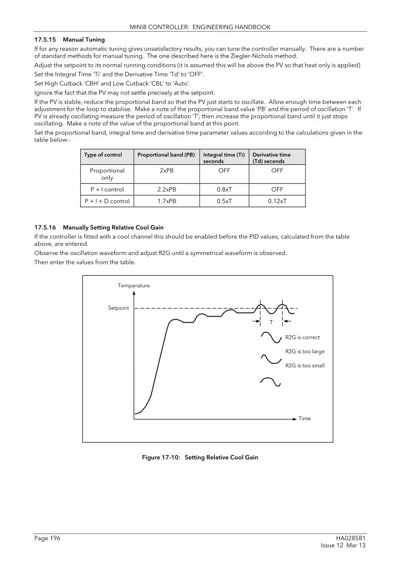
MINI8 CONTROLLER: ENGINEERING HANDBOOK
Page 196 HA028581 Issue 12 Mar 13
17.5.15 Manual Tuning If for any reason automatic tuning gives unsatisfactory results, you can tune the controller manually. There are a number of standard methods for manual tuning. The one described here is the Ziegler-Nichols method.
Adjust the setpoint to its normal running conditions (it is assumed this will be above the PV so that heat only is applied)
Set the Integral Time ‘Ti’ and the Derivative Time ‘Td’ to ‘OFF’.
Set High Cutback ‘CBH’ and Low Cutback ‘CBL’ to ‘Auto’.
Ignore the fact that the PV may not settle precisely at the setpoint.
If the PV is stable, reduce the proportional band so that the PV just starts to oscillate. Allow enough time between each adjustment for the loop to stabilise. Make a note of the proportional band value ‘PB’ and the period of oscillation ‘T’. If PV is already oscillating measure the period of oscillation ‘T’, then increase the proportional band until it just stops oscillating. Make a note of the value of the proportional band at this point.
Set the proportional band, integral time and derivative time parameter values according to the calculations given in the table below:-
Type of control Proportional band (PB) Integral time (Ti) seconds
Derivative time (Td) seconds
Proportional only
2xPB OFF OFF
P + I control 2.2xPB 0.8xT OFF
P + I + D control 1.7xPB 0.5xT 0.12xT
17.5.16 Manually Setting Relative Cool Gain If the controller is fitted with a cool channel this should be enabled before the PID values, calculated from the table above, are entered.
Observe the oscillation waveform and adjust R2G until a symmetrical waveform is observed.
Then enter the values from the table.
Figure 17-10: Setting Relative Cool Gain
Temperature
Time
Setpoint
T
R2G is correct R2G is too large R2G is too small

MINI8 CONTROLLER: ENGINEERING HANDBOOK
HA028581 Page 197 Issue 12 Mar 13
17.5.17 Manually Setting the Cutback Values Enter the PID terms calculated from the table in section 17.5.15 before setting cutback values.
The above procedure sets up the parameters for optimum steady state control. If unacceptable levels of overshoot or undershoot occur during start-up, or for large step changes in PV, then manually set the cutback parameters.
Proceed as follows:
Initially set the cutback values to one proportional bandwidth converted into display units. This can be calculated by taking the value in percentage that has been installed into the parameter ‘PB’ and entering it into the following formula:-
PB/100 * Span of controller = Cutback High and Cutback Low
For example, if PB = 10% and the span of the controller is 0 -1200OC, then
Cutback High and Low = 10/100 * 1200 = 120
If overshoot is observed following the correct settings of the PID terms increase the value of ‘CBL’ by the value of the overshoot in display units. If undershoot is observed increase the value of the parameter ‘CBH’ by the value of the undershoot in display units.
Figure 17-11: Manual Setting of Cutback
Display Units
Setpoint Initial overshoot
PV approaching SP from below – adjust CBL
Initial undershoot
PV approaching SP from above – adjust CBH
Time

MINI8 CONTROLLER: ENGINEERING HANDBOOK
Page 198 HA028581 Issue 12 Mar 13
17.6 Setpoint Function Block For each of the 16 loops, the controller setpoint is the Working Setpoint that may come from a number of alternative sources. This is the value ultimately used to control the process variable in each loop.
The working setpoint may be derived from:-
1. SP1 or SP2, both of which are individually set, can be selected by an external signal or via the SPSelect parameter over communications.
2. From an external (remote) analogue source
3. The output of a programmer function block and will, therefore, vary in accordance with the program in use.
The setpoint function block also provides the facility to limit the rate of change of the setpoint before it is applied to the control algorithm. It will also provide upper and lower limits. These are defined as setpoint limits for the local setpoints and instrument range high and low for other setpoint sources. All setpoints are ultimately subject to a limit of range hi and range lo.
User configurable methods for tracking are available, such that the transfer between setpoints and between operational modes will not cause a bump in the setpoint.
17.6.1 Setpoint Function Block
Figure 17-12: Setpoint Function Block
Target SP
Programmer SP PSP1 PSP2 PSP3
Range Max
Range Min
Remote SP
PSP High Lim
PSP Low Lim
SP2 Enab
SP1 Enab SP1 High Limit
SP1 Low Limit
SP2
SP1
SP2 High Limit
SP2 Low Limit
Remote + Local Trim
Prog
Local
+ Local Trim
Remote
Local
Trim High
Trim Low
Local SP + RemoteTrim
Remote only
+
Ramp
Other inputs: PV Ramp rate Servo SP changed
Range Max
Range Min
Working SP
Target SP
Ramp Status
Enable Rem SP
Remote Type

MINI8 CONTROLLER: ENGINEERING HANDBOOK
HA028581 Page 199 Issue 12 Mar 13
17.6.2 SP Tracking When setpoint tracking is enabled and the local setpoint is selected, the local setpoint is copied to ‘TrackSP’. Tracking now ensures that the alternate SP follows or tracks this value. When the alternate setpoint is selected it initially takes on the tracked value thus ensuring that no bump takes place. The new setpoint is then adopted gradually. A similar action takes place when returning to the local setpoint.
17.6.3 Manual Tracking When the controller is operating in manual mode the currently selected SP tracks the PV. When the controller resumes automatic control there will be no step change in the resolved SP.
17.6.4 Rate Limit
Rate limit will control the rate of change of setpoint. It is enabled by the ‘Rate’ parameter. If this is set to Off then any change made to the setpoint will be effective immediately. If it is set to a value then any change in the setpoint will be effected at the value set in units per minute. Rate limit also acts on SP2 and when switching between SP1 and SP2.
When rate limit is active the ‘RateDone’ parameter will display ‘No’. When the setpoint has been reached this parameter will change to ‘Yes’.
When ‘Rate’ is set to a value (other than Off) an additional parameter ‘SPRate Disable’ is displayed which allows the setpoint rate limit to be turned off and on without the need to adjust the ‘Rate’ parameter between Off and a value.
17.6.5 Setpoint Parameters
Folder – Loop.1 to Loop.16 Sub-folder: SP
Name
Parameter Description Value
Default Access Level
Range High The Range limits provide a set of absolute maximums and minimums for setpoints within the control loop. Any derived setpoints are ultimately clipped to be within the Range limits.If the Proportional Band is configured as % of Span, the span is derived from the Range limits.
Full range of the input type Conf
Range Low Conf
SP Select Select local or alternate setpoint SP1 SP2
Setpoint 1 Setpoint 2
SP1 Oper
SP1 Primary setpoint for the controller Between SP high and SP low limits Oper
SP2 Setpoint 2 is the secondary setpoint of the controller. It is often used as a standby setpoint.
Oper
SP HighLimit Maximum limit allowed for the local setpoints
Between Range Hi and Range Lo Oper
SP LowLimit Minimum limit allowed for the local setpoints
Oper
Alt SP Select To enable the alternative setpoint to be used. This may be wired to a source such as the programmer Run input.
No Yes
Alternative setpoint disabled Alternative setpoint enabled
Oper
Alt SP This may be wired to an alternative source such as the programmer or remote setpoint
Oper
Rate Limits the maximum rate at which the working setpoint can change. The rate limit may be used to protect the load from thermal shock which may be caused by large step changes in setpoint.
Off or 0.1 to 9999.9 engineering units per minute
Off Oper
RateDone Flag which indicates when the setpoint is changing or completed
No Yes
Setpoint changing Complete
R/O
Rate Disable Setpoint rate disable No Yes
Enabled Disabled
Oper

MINI8 CONTROLLER: ENGINEERING HANDBOOK
Page 200 HA028581 Issue 12 Mar 13
Folder – Loop.1 to Loop.16 Sub-folder: SP
Name
Parameter Description Value
Default Access Level
ServoToPV Servo to PV Enable When Rate is set to any value other than Off and Servo to PV is enabled, changing the active SP will cause the working SP to servo to the current PV before ramping to the new target SP.
No Yes
Disabled Enabled
No Conf R/O in L3
SP Trim Trim is an offset added to the setpoint. The trim may be either positive or negative, the range of the trim may be restricted by the trim limits Setpoint trims may be used in a retransmission system. A master zone may retransmit the setpoint to the other zones, a local trim may be applied to each zone to produce a profile along the length of the machine
Between SP Trim Hi and SP Trim Lo Oper
SPTrim HighLimit
Setpoint trim high limit Oper
SPTrim LowLimit
Setpoint trim low limit Oper
ManualTrack To enable manual tracking. When the loop is switched from Manual to Auto, the Setpoint is set to the current PV. This is useful if the load is started in Manual Mode, then later switched to Auto to maintain the operating point.
Off On
Manual tracking disabled Manual tracking enabled
R/O
SP Track Setpoint tracking ensures bumpless transfer in setpoint when switching between a local and an alternate setpoint such as the programmer. This enables the tracking interface provided by TrackPV and TrackVal, which is used by the programmer and other setpoint providers external to the control loop
Off On
Setpoint tracking disabled Setpoint tracking enabled
Conf
Track PV The programmer tracks the PV when it is servoing or tracking.
R/O
Track SP Manual Tracking Value. The SP to track for manual tracking.
R/O
SPIntBal SP Integral Balance This is also known as debump in some instances. It forces the integral to be balanced upon changes in target setpoint
Off On
Off L3 R/O Alterable in config

MINI8 CONTROLLER: ENGINEERING HANDBOOK
HA028581 Page 201 Issue 12 Mar 13
17.6.6 Setpoint Limits The setpoint generator provides limits for each of the setpoint sources as well as an overall set of limits for the loop. These are summarised in the diagram below.
Figure 17-13: Setpoint Limits
☺ ‘Range High’ and ‘Range Low’ provide the range information for the control loop. They are used in control calculations to generate proportional bands. Span = Range High – Range Low.
17.6.7 Setpoint Rate Limit Allows the rate of change of setpoint to be controlled. This prevents step changes in the setpoint. It is a simple symmetrical rate limiter and is applied to the working setpoint which includes setpoint trim. It is enabled by the ‘Rate’ parameter. If this is set to Off then any change made to the setpoint will be effective immediately. If it is set to a value then any change in the setpoint will be effected at the value set in units per minute. Rate limit applies to SP1, SP2 and Remote SP.
When rate limit is active the ‘RateDone’ flag will display ‘No’. When the setpoint has been reached this parameter will change to ‘Yes’. This flag will be cleared if the target setpoint subsequently changes.
When ‘Rate’ is set to a value (other than Off) an additional parameter ‘Rate Disable’ is displayed which allows the setpoint rate limit to be turned off and on without the need to adjust the ‘Rate’ parameter between Off and a value.
If the PV is in sensor break, the rate limit is suspended and the working setpoint takes the value of 0. On sensor break being released the working setpoint goes from 0 to the selected setpoint value at the rate limit.
SPTrim HighLimit
SPTrim LowLimit
Range High
SP HighLimit
LoopAlm setpoints
SP LowLimit
Range Low
Remote SP1 SP2 TgtSP WSP SP Trim

MINI8 CONTROLLER: ENGINEERING HANDBOOK
Page 202 HA028581 Issue 12 Mar 13
17.6.8 Setpoint Tracking The setpoint used by the controller may be derived from a number of sources. For example:-
1. Local setpoints SP1 and SP2. These may be selected using the parameter ‘SP Select’ in the SP folder, through digital communications or by configuring a digital input which selects either SP1 or SP2. This might be used, for example, to switch between normal running conditions and standby conditions. If Rate Limit is switched off the new setpoint value is adopted immediately when the switch is changed.
2. A programmer generating a setpoint which varies over time, see Chapter18. When the programmer is running the ‘Track SP’ and ‘Track PV’ parameters update continuously so that the programmer can perform its own servo (see also section 18.7.1). This is sometimes referred to as ‘Program Tracking’.
3. From a Remote analogue source. The source could be an external analogue input into an analogue input module wired to the ‘Alt SP’ parameter or a User Value wired to the ‘Alt SP’ parameter. The remote setpoint is used when the parameter ‘Alt SP Select’ is set to ‘Yes’.
Setpoint tracking (sometimes referred to as Remote Tracking) ensures that the Local setpoint adopts the Remote setpoint value when switching from Local to Remote to maintain bumpless transfer from Remote to Local. Bumpless transfer does not take place when changing from Local to Remote. Note, that if Rate Limit is applied the setpoint will change at the rate set when changing from Local to Remote.
17.6.9 Manual Tracking When the controller is operating in manual mode the currently selected SP (SP1 or SP2) tracks the PV. When the controller resumes automatic control there will be no step change in the resolved SP. Manual tracking does not apply to the remote setpoint or programmer setpoint.

MINI8 CONTROLLER: ENGINEERING HANDBOOK
HA028581 Page 203 Issue 12 Mar 13
17.7 Output Function Block The output function block allows you to set up output conditions from the control block, such as output limits, hysteresis, output feedforward, behaviour in sensor break, etc.
Folder – Loop.1 to Loop.16 Sub-folder: OP
Name Parameter Description Value Default Access Level
Output High Limit
Maximum output power delivered by channels 1 and 2. By reducing the high power limit, it is possible to reduce the rate of change of the process, however, care should be taken as reducing the power limit will reduce the controllers ability to react to disturbance.
Between Output Lo and 100.0% 100.0 Oper
Output Low Limit
Minimum (or maximum negative) output power delivered by channels 1 and 2
Between Output Hi and -100.0% -100.0
Ch1 Out Channel 1 (Heat) output. The Ch1 output is the positive power values (0 to Output Hi) used by the heat output. Typically this is wired to the control output (time proportioning or DC output).
Between output Hi and Output Lo R/O
Ch2 Out The Ch2 output is negative portion of the control output (0 – Output Lo) for heat/cool applications. It is inverted to be a positive number so that it can be wired into one of the outputs (time proportioning or DC outputs).
Between output Hi and Output Lo R/O
Ch2 DeadBand
Ch1/Ch2 Deadband is a gap in percent between output 1 going off and output 2 coming on and vice versa. For on/off control this is taken as a percentage of the hysteresis.
Off to 100.0% Off Oper
Rate Limits the rate at which the output from the PID can change in % change per minute. Output rate limit is useful in preventing rapid changes in output from damaging the process or the heater elements.
Off to 9999.9 percent per minute Off Oper
Rate Disable Output rate disable No Yes
Enabled Disabled
Oper
Ch1 OnOff Hysteresis
Channel hysteresis only shown when channel 1 is configured as OnOff. Hysteresis sets the difference between output on and output off to prevent (relay) chatter.
0.0 to 200.0 10.0 Oper
Ch2 OnOff Hysteresis
0.0 to 200.0 10.0 Oper
SensorBreak Mode
Defines the action taken if the Process Variable is bad, i.e. the sensor has failed. This can be configured as hold, in which case the output of the loop is held at its last good value. Alternately the output can switch to a safe output power defined at configuration.
Safe
Hold
To select the level set by ‘Safe OP’ To hold the current output level at the point when sensor break occurs
Safe Oper
Safe OP Val Sets the output level to be adopted when loop is inhibited
Between output Hi and Output Lo 0 Oper

MINI8 CONTROLLER: ENGINEERING HANDBOOK
Page 204 HA028581 Issue 12 Mar 13
Folder – Loop.1 to Loop.16 Sub-folder: OP
Name Parameter Description Value Default Access Level
SbrkOp Sets the output level to be adopted when in sensor break condition.
Between output Hi and Output Lo 0 Oper
Manual Mode Selects the mode of manual operation.
Track
In auto the manual output tracks the control output such that a change to manual mode will not result in a bump in the output.
Oper
Step On transition to manual the output will be the manual op value as last set by the operator.
ManualOutVal The output when the loop is in manual. Note: In manual mode the controller will still limit the maximum power to the power limits, however, it could be dangerous if the instrument is left unattended at a high power setting. It is important that the over range alarms are configured to protect your process. We recommend that all processes are fitted with an independent over range "policeman"
Between output Hi and Output Lo R/O
ForcedOP Forced manual output value. When ‘Man Mode’ = ‘Step’ the manual output does not track and on transition to manual the target output will step from its current value to the ‘ForcedOP’ value.
-100.0 to 100.0 0.0 Oper
Cool Type Selects the type of cooling channel characterisation to be used. Can be configured as water, oil or fan cooling.
Linear Oil Water Fan
These are set to match the type of cooling medium applicable to the process
Conf
FeedForward Type
Feedforward type The following four parameters appear if FF Type ≠ None
None No signal fed forward None Conf
Remote A remote signal fed forward
SP Setpoint fed forward
PV PV fed forward
FeedForward Gain
Defines the gain of the feedforward value, the feed forward value is multiplied by the gain
Conf
FeedForward Offset
Defines the offset of the feedforward value this is added to the scaled feedforward.
Oper
FeedForward Trim Limit
Feedforward trim limits the effect of the PID output. Defines symmetrical limits around the PID output, such that this value is applied to the feedforward signal as a trim.
Oper

MINI8 CONTROLLER: ENGINEERING HANDBOOK
HA028581 Page 205 Issue 12 Mar 13
Folder – Loop.1 to Loop.16 Sub-folder: OP
Name Parameter Description Value Default Access Level
FF_Rem Remote Feedforward signal. Allows an another signal to be used as Feedforward.
This is not affected by FeedForward Gain or Offset
R/O
FeedForward Val
The calculated Feedforward Value. R/O
TrackOutVal Value for the loop output to track when OP Track is Enabled.
Track Enable When enabled, the output of the loop will follow the track output value. The loop will bumplessly return to control when tracking is turned off.
Off On
Disabled Enabled
Oper
RemOPL Remote output low limit. Can be used to limit the output of the loop from a remote source or calculation. This must always be within the main limits.
-100.0 to 100.0 Oper
RemOPH Remote output high limit -100.0 to 100.0 Oper

MINI8 CONTROLLER: ENGINEERING HANDBOOK
Page 206 HA028581 Issue 12 Mar 13
17.7.1 Output Limits The diagram shows where output limits are applied.
Figure 17-14: Output Limits
• Individual output limits may be set in the PID list for each set of PID parameters when gain scheduling is used.
• The parameters ‘SchedOPHi’ and ‘SchedOPHLo’, found the Diagnostics folder, may be set to values which override the gain scheduling output values.
• A limit may also be applied from an external source. These are ‘RemOPH’ and ‘RemOPLo’ (Remote output high and low) found in the Output folder. These parameters are wireable. For example they may be wired to an analogue input module so that a limit may applied through some external strategy. If these parameters are not wired +100% limit is applied every time the instrument is powered up.
• The tightest set (between Remote and PID) is connected to the output where an overall limit is applied using parameters ‘Output High Limit’ and ‘Output Low Limit’ settable in Oper Level.
• ‘Wrk OPHi’ and ‘Wrk OPHLo’ found in the Diagnostics folder are read only parameters showing the overall working output limits.
The tune limits are a separate part of the algorithm and are applied to the output during the tuning process. The overall limits ‘Output High Limit’ and ‘Output Low Limit’ always have priority.
Working output
OPHi3 +100
OPLo3 -100
TuneOPH
TuneOPL
OPHi +100
OPLo -100
SchedOPHi SchedOPLo
PID List Including Gain
Scheduling output limits
Min
RemOPH +100% RemOPL –100%
Output High limit Output Low Lim
WrkOPHi WrkOPLo
Diagnostics Read only
Writable NOT Wireable
Output Level 3
Writable NOT Wireable
OPL limiting to +ve
Writable AND Wireable
Tune
Output List
OPHi2 +100
OPLo2 -100
Diag List

MINI8 CONTROLLER: ENGINEERING HANDBOOK
HA028581 Page 207 Issue 12 Mar 13
17.7.2 Output Rate Limit The output rate limiter is a simple rate of change limiter which will prevent the control algorithm demanding step changes in output power. It may be set in percent per minute.
The rate limit is performed by determining the direction in which the output is changing, and then incrementing or decrementing the Working Output (‘ActiveOut’ in the Main folder) until ‘ActiveOut’ = the required output.
The amount by which to increment or decrement will be calculated based on the sampling rate of the algorithm (i.e. 110ms) and the rate limit that has been set. If the change in output is less than the rate limit increment the change will take effect immediately.
The rate limit direction and increment will be calculated on every execution of the rate limit. Therefore, if the rate limit is changed during execution, the new rate of change will take immediate effect. If the output is changed whilst rate limiting is taking place, the new value will take immediate effect on the direction of the rate limit and in determining whether the rate limit has completed.
The rate limiter is self-correcting such that if the increment is small and is lost in the floating point resolution, the increment will be accumulated until it takes effect.
The output rate limit will remain active even if the loop is in manual mode
17.7.3 Sensor Break Mode Sensor break is detected by the measurement system and a flag is passed to the control block which indicates sensor failure. On the loop being informed that a sensor break has occurred it may be configured using ‘SensorBreak Mode’ to respond in one of two ways. The output may go to a pre-set level or remain at its current value.
The pre-set value is defined by the parameter ‘SbrkOP’. If rate limit is not configured the output will step to this value otherwise it will ramp to this value at the rate limit.
If configured as ‘Hold’ the output of the loop will stay at its last good value. If Output Rate Limit (Rate) has been configured a small step may be seen as the working output will limit to the 2 second old value.
On exit from sensor break the transfer is bumpless – the power output will ramp from its pre-set value to the control value.
17.7.4 Forced Output This feature enables the user to specify what the output of the loop should do when moving from automatic control to manual control. The default is that the output power will be maintained and is then editable by the user. If forced manual is enabled, two modes of operation can be configured. The forced manual step setting means the user can set a manual output power value and on transition to manual the output will be forced to that value. If ‘Track Enable’ is enabled the output steps to the forced manual output and then subsequent edits to the output power are tracked back into the manual output value.
The parameters associated with this feature are ‘ForcedOP’ and ‘ManualMode’ = ‘Step’.

MINI8 CONTROLLER: ENGINEERING HANDBOOK
Page 208 HA028581 Issue 12 Mar 13
17.7.5 Feedforward Feedforward is a value, which is scaled and added to the PID output, before any limiting. It can be used for the implementation of cascade loops or constant head control. Feedforward is implemented such that the PID output is limited to trim limits and acts as a trim on a FeedForward Value. The FeedForward Val is derived either from the PV or setpoint by scaling the PV or SP by the ‘FeedForward Gain’ and ‘FeedForward Offset’. Alternatively, a remote value may be used for the FeedForward Val, this is not subject to any scaling. The resultant FeedForward Val is added to the limited PID OP and becomes the PID output as far as the output algorithm is concerned. The feedback value then generated must then have the FF contribution removed before being used again by the PID algorithm. The diagram below shows how feedforward is implemented
Figure 17-15: Implementation of Feedforward
PID Output Algorithm
SP1
PV
SP
PV
FeedForward Offset
Gain
FeedForward Gain
FeedForward Type
FeedForward Type
Remote
TrimHI
TrimLo
Feedback
Output
- +
+
+
+ +
FeedForward Trim Limit

MINI8 CONTROLLER: ENGINEERING HANDBOOK
HA028581 Page 209 Issue 12 Mar 13
17.7.6 Effect of Control Action, Hysteresis and Deadband
For temperature control ‘Loop.1.Control Action’ will be set to ‘Reverse’. For a PID controller this means that the heater power decreases as the PV increases. For an on/off controller output 1 (usually heat) will be on (100%) when PV is below the setpoint and output 2 (usually cool) will be on when PV is above the setpoint
Hysteresis applies to on/off control only. It defines the difference in temperature between the output switching off and switching back on again. The examples below show the effect in a heat/cool controller.
Deadband (Ch2 DeadB) can operate on both on/off control or PID control where it has the effect of widening the period when no heating or cooling is applied. However, in PID control its effect is modified by both the integral and derivative terms. Deadband might be used in PID control, for example, where actuators take time to complete their cycle thus ensuring that heating and cooling are not being applied at the same time. Deadband is likely to be used, therefore, in on/off control only. The second example below adds a deadband of 20 to the above example.
Figure 17-16: Deadband OFF
Figure 17-17: Deadband ON set at 50% of Cooling. Hysteresis =5oC
SP 300oC
HYST.C
HYST.H
OP1 On Heating 100%
No OP
OP2 On Cooling 100%
Heating and Cooling Type both on/off
Setpoint = 300oC
Control Action = reverse
Heating Hysteresis = 8oC
Cooling Hysteresis = 10oC
Deadband = OFF
Heating off at SP (300oC)
Cooling on at SP + HYST.C
(310oC)
Cooling off at SP (300oC)
Heating on at SP – HYST.H
(292oC)
SP 300oC
HYST.C
HYST.H
Heating and Cooling Type both on/off
Setpoint = 300oC
Control Action = reverse
Heating Hysteresis = 8oC
Cooling Hysteresis = 10oC
Deadband 50% of cooling hysteresis = 5oC
Heating off at SP (300oC)
Cooling on at SP + HYST.C
(310oC)
Cooling off at D.BAND
(305oC)
Heating on at SP – HYST.H
(292oC)
D.BAND
Power deadband
OP1 On Heating 100%
No OP
OP2 On Cooling 100%

MINI8 CONTROLLER: ENGINEERING HANDBOOK
Page 210 HA028581 Issue 12 Mar 13
18. Chapter 18 Setpoint Programmer 18.1 INTRODUCTION In a setpoint programmer you can set up a profile in the controller in which the setpoint varies in a pre-determined way over a period of time. Temperature is a very common application where it is required to ‘ramp’ the process value from one level to another over a set period of time. The Program is divided into a flexible number of Segments - each being of a single time duration. It is often necessary to switch external devices at particular times during the program. Up to eight digital ‘event’ outputs can be programmed to operate during those segments. An example of a program and two event outputs is shown below.
Figure 18-1: A Setpoint Program
18.1.1 Time to Target Programmer
Each segment consists of a single duration parameter and a set of target values for the profiled variables.
1. The duration specifies the time that the segment takes to change the profiled variables from their current values to the new targets.
2. A dwell type segment is set up by leaving the target setpoint at the previous value. 3. A Step type segment is set up by setting the segment time to zero.
A program with all segments configured as Time-to-Target is shown below.
Figure 18-2: Time to Target Programmer
Segment
Profile Setpoint
Start (Run) 2h 1h 3h 4h 5h 6h 7h 8h Time
Program
2
1
8 X Digital Events
PV
Segment 1 Target
Segment 1 Time
4 min 3 min 4 min 2 min
Time Time Time Time 100
50
0
Setpoint
Time

MINI8 CONTROLLER: ENGINEERING HANDBOOK
HA028581 Page 211 Issue 12 Mar 13
18.1.2 Ramp Rate Programmer A ramp rate programmer specifies it's ramp segments as maximum setpoint changes per time unit.
Each segment can be specified by the operator as Ramp Rate, Dwell or Step.
1. Ramp Rate – the setpoint changes at a rate in units/time
2. Dwell – the time period is set – there is no need to set the target value as this is inherited from the previous segment
3. Step – specify target setpoint only – the controller will use that setpoint when the segment is reached
The diagram below shows an example of a ramp rate programmer.
Figure 18-3: Ramp Rate Programmer
18.2 Mini8 Controller Programmer Block(s) Mini8 Controller Version 2.xx have 8 programmer blocks available. Each of these blocks has one program of up to 16 segments. One block may be wired to all 16 loops or up to 8 loops may have their own programmer block. In this situation Loop 1, Programmer block 1 and program 1 are associated together, Loop 2, Programmer block 2 and program 2 are associated together, and so on up to Loop 8, Programmer block 8 and program 8 being associated together. Mini8 Controller Version 1.xx have a single programmer block. The total number of segments available is 200 or 50 per program and it is possible to store up to 50 separate programs. Parameter tables of this version are included in Appendix D.
Note: Version 1.xx Mini8 controller clone files with programs included will not load correctly into a version 2.xx Mini8.
25 per min 3 min 12.5 per min 25 min
Ramp Dwell Ramp Ramp 100
50
0
Setpoint
Time

MINI8 CONTROLLER: ENGINEERING HANDBOOK
Page 212 HA028581 Issue 12 Mar 13
18.3 Segment Types Depending on the type of program configured, a segment may be set as:-
18.3.1 Rate A Ramp segment provides a controlled change of setpoint from an original to a target setpoint. The duration of the ramp is determined by the rate of change specified. Two styles of ramp are possible in the range, Ramp-Rate or Time-To-Target.
The segment is specified by the target setpoint and the desired ramp rate. The ramp rate parameter is presented in engineering units (oC, oF, Eng.) per real time units (Seconds, Minutes or Hours). If the units are changed, all ramp rates are re-calculated to the new units and clipped if necessary
18.3.2 Dwell The setpoint remains constant for a specified period at the specified target. The operating setpoint of a dwell is inherited from the previous segment.
18.3.3 Step The setpoint changes instantaneously from its current value to a new value at the beginning of a segment. A Step segment has a minimum duration of 1 second.
18.3.4 Time A time segment defines the duration of the segment. In this case the target setpoint is defined and the time taken to reach this value. A dwell period is set by making the target setpoint the same value as the previous setpoint.
18.3.5 GoBack Go Back allows segments in a program to be repeated a set number of times. The diagram shows an example of a program which is required to repeat the same section a number of times and then continue the program.
When planning a program it is advisable to ensure that the end and start setpoints of the program are the same otherwise it will step to the different levels. A Go Back segment is defined when editing a program.
‘Goback Seg’ specifies the segment to go back to
‘Goback Cycles’ specifies the number of times the goback loop is executed
Overlapping Goback loops are disallowed
Note 1. If a second or more ‘Go Back’ segments are created, they cannot return to a segment before the previous ‘Go Back’ segment as shown.
In this diagram a Go Back segment can be created from 3 to 2 or 1. Go Back segments can also be created from 7 to 6 or 5 or 4 but not from 7 to 2 or 1
Segment 1 Segment 2 Segment 7 Segments 3 to 6
At this point Go Back To segment 3
Segment 6 is defined as a Go Back segment
This section is repeated ‘n’ times
Segments
1 2 3 - Go Back 7 - Go Back 4 5 6
Not allowable
OK OK OK OKOK

MINI8 CONTROLLER: ENGINEERING HANDBOOK
HA028581 Page 213 Issue 12 Mar 13
18.3.6 Wait Wait specifies the criterion for which a segment cannot proceed to the next segment. Any segment can be defined as ‘Wait’ in the ‘Program Edit’ page. The next parameter is then ‘Wait For’ and here you define the criterion.
‘Wait For’ criteria:- None No action PrgIn1 Wait until Input 1 is true PrgIn2 Wait until Input 2 is true PrgIn1n2 Wait until Input 1 AND Input 2 are true PrgIn1or2 Wait until Input 1 OR Input 2 is true PVWaitIP Wait until PV has met the criteria against the parameter ‘WaitVal’ as shown:
Example where the temperature must have reached 550 °C before the program continues:
This and subsequent screen shots are from the Programmer editor in iTools.
Wait segments do not have Events or Holdback.
18.3.7 End A program may contain one End segment. This allows the program to be truncated to the number of segments required.
The end segment can be configured to have an indefinite dwell at the last target setpoint or to reset to the start of the program or to go to a defined level of power output (SafeOP). This is selectable by the user.
If a number of program cycles are specified for the program, then the End segment is not executed until the last cycle has completed
‘Wait For’ set to ‘PVWaitIP’ PSP = 100 ‘WaitVal’ = 5
PVWait Segment will wait until
Abs Hi PVWaitIP >= 5
Dev Lo PVWaitIP >= 95
Abs Lo PVWaitIP <= 5
Dev Hi PVWaitIP <= 105

MINI8 CONTROLLER: ENGINEERING HANDBOOK
Page 214 HA028581 Issue 12 Mar 13
18.4 Output Events Program segments have configurable events. ‘Wait’ ‘GoBack’ and ‘End’ segments do not have events.
There are up to 8 digital events, PV Events and Time Events.
18.4.1 Digital Events These are digital flags which can be set on or off for each of the segments.
These are enabled by setting Programmer.n.Setup.MaxEvents to the required maximum number of events (>0 and <=8).
Clicking the icon on the right in an ‘EventOuts’ cell opens digital events window:
In this example Programmer.n.Setup.MaxEvents has been set to 4. Tick the boxes of the outputs that are required. The value shown is the bit mask for the outputs (10 = 2 + 8 I.e. outputs 2 and 4)
The EventOuts row above shows this setup for each segment.

MINI8 CONTROLLER: ENGINEERING HANDBOOK
HA028581 Page 215 Issue 12 Mar 13
18.4.2 PV Event & User Value PV Events are essentially a simplified analogue alarm per segment based on the programmer PV input. For this feature the Programmer.n.Setup.EnablePVEvent must be set to ‘Yes’. The PV Event Output (PVEventOP) may be used to trigger the required response.
• Each Segment has one PV Event Type (Off, Hi, Lo, Dev Hi, Dev Lo, Dev Band*) • Each Segment has one PV Threshold
* Dev refers to deviation of the PV parameter from Programmer Setpoint (i.e. there is no reference input).
If the PVEvent type is set to None in a segment then the User value may be used as a general purpose analogue value per segment. For this feature the Programmer.n.Setup.EnableUValue must be set to ‘Yes’. By default, the parameter is named ‘UserVal’ – it may be renamed in Programmer.n.Setup.UValName.
In segment 1 there is no PVEvent so the UserVal may be set but in segment 3 the PVEvent type is not ‘None’ so only the PVThreshold may be set.
The event output is Programmer.n.Setup.PVEventOP, the UserVal output is Programmer.n.Setup.UserValOP
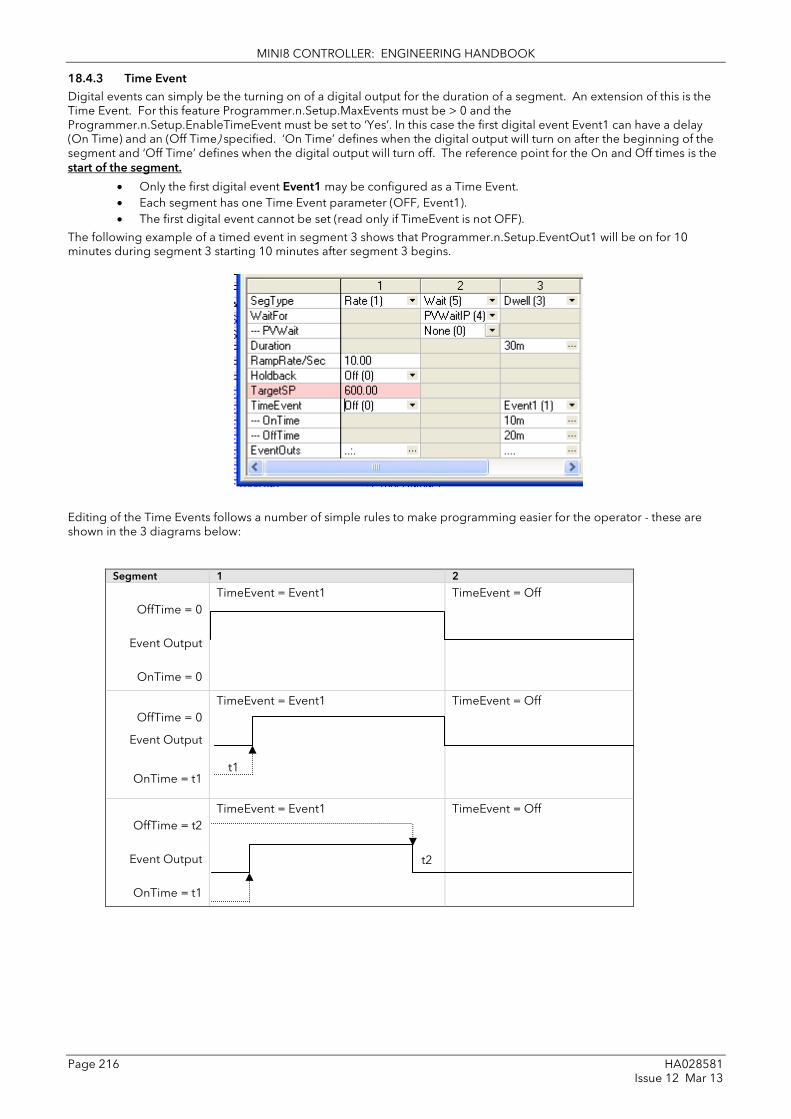
MINI8 CONTROLLER: ENGINEERING HANDBOOK
Page 216 HA028581 Issue 12 Mar 13
18.4.3 Time Event Digital events can simply be the turning on of a digital output for the duration of a segment. An extension of this is the Time Event. For this feature Programmer.n.Setup.MaxEvents must be > 0 and the Programmer.n.Setup.EnableTimeEvent must be set to ‘Yes’. In this case the first digital event Event1 can have a delay (On Time) and an (Off Time) specified. ‘On Time’ defines when the digital output will turn on after the beginning of the segment and ‘Off Time’ defines when the digital output will turn off. The reference point for the On and Off times is the start of the segment.
• Only the first digital event Event1 may be configured as a Time Event. • Each segment has one Time Event parameter (OFF, Event1). • The first digital event cannot be set (read only if TimeEvent is not OFF).
The following example of a timed event in segment 3 shows that Programmer.n.Setup.EventOut1 will be on for 10 minutes during segment 3 starting 10 minutes after segment 3 begins.
Editing of the Time Events follows a number of simple rules to make programming easier for the operator - these are shown in the 3 diagrams below:
Segment 1 2
OffTime = 0
Event Output
OnTime = 0
TimeEvent = Event1 TimeEvent = Off
OffTime = 0
Event Output
OnTime = t1
TimeEvent = Event1 TimeEvent = Off
OffTime = t2
Event Output
OnTime = t1
TimeEvent = Event1
TimeEvent = Off
t1
t2

MINI8 CONTROLLER: ENGINEERING HANDBOOK
HA028581 Page 217 Issue 12 Mar 13
Segment 1 2
OffTime
Event Output
OnTime
TimeEvent = Event1
TimeEvent = On
OffTime
Event Output
OnTime = 0
Time Event = Event1
Time Event = Off
OffTime
Event Output
OnTime
Time Event = Event1 TimeEvent = Off
• To configure an event which straddles two segments configure Ton in Segment n and Toff in segment n+1.
Segment 1 2
OffTime
OnTime
Event Output Off
Time Event = Event1
Time Event = Off
OffTime
OnTime
Event Output Off
Time Event = Event1 Time Event = Off
OffTime
OnTime
Event Output Off
Time Event = Event1 Time Event = Off
OnTime and OffTime are extended by G.Soak periods. If OnTime = 0, the output goes hi at the start of the segment but OffTime is not decremented while Gsoak Wait is applied. Timed event outputs are on a total of Gsoak Wait + (OffTime – OnTime).
In the event of a power fail, time events timing will be unaffected.
OffTime OffTime * = 0
OnTime=0
Error : OnTime = OffTimeEvent OP = Off
Error : OnTime > OffTime Event OP = Off
Error : OffTime > segment 1 duration
Error : OnTime > seg 1 duration Event OP = Off

MINI8 CONTROLLER: ENGINEERING HANDBOOK
Page 218 HA028581 Issue 12 Mar 13
18.5 Holdback Holdback freezes the program if the process value (PV) does not track the setpoint (SP) by more than a user defined amount. The programmer will remain in HOLDBACK until the PV returns to within the requested deviation from setpoint.
In a Ramp it indicates that the PV is lagging the SP by more than the set amount and that the program is waiting for the process to catch up.
Holdback maintains the correct soak period for the product – see Guaranteed Soak below.
Each program can be configured with a holdback value. Each segment determines the holdback function.
Holdback will cause the execution time of the program to extend, if the process cannot match the demanded profile.
Holdback state will not change access to the parameters. The parameters will behave as if in the RUN state.
The diagram below demonstrates that the demanded setpoint (SP) will only change at the rate specified by the program when the PV's deviation is less than the holdback value. When the Deviation between the setpoint and PV is greater than the holdback value (HBk Val) the setpoint ramp will pause until the deviation returns to within the band.
The next segment will not start until the deviation between Setpoint and PV is less than the holdback value.
Four types of Holdback are available:-
None Holdback is disabled for this segment.
High Holdback is entered when the PV is greater than the Setpoint plus HBk Val.
Low Holdback is entered when the PV is lower than the Setpoint minus HBk Val.
Band Holdback is entered when the PV is either greater than the Setpoint plus HBk Val or lower than the Setpoint minus HBk Val
18.5.1 Guaranteed Soak Guaranteed Soak (guaranteed time workpiece stays at SP within a specified tolerance) is achieved in the previous single programmer version by using Holdback Band during a dwell segment. Since only one holdback value per program is available, this imposes a limitation where different tolerance values are required to guarantee the soak.
In 2.xx Mini8 controller Holdback Type in Dwell segments is replaced by a Guaranteed Soak Type (G.Soak) which can be set as Off, Lo, Hi or Band. A Guaranteed Soak Value (G.Soak Val) is available in Dwell segments and this provides the ability to set different values in any Dwell segment.
SP as set in the program
SP as modified by holdback follows the rate at which the process is capable
PV
PV lags SP. Holdback stops the ramp until SP catches up. Set Holdback Type to low
Dwell starts when PV reaches correct value
Dwell held if PV falls beyond limits
Dwell extended by t1+t2
t1 t2 SP/PV
Time

MINI8 CONTROLLER: ENGINEERING HANDBOOK
HA028581 Page 219 Issue 12 Mar 13
18.6 PID Select It is possible to set up three sets of PID values, see section 17.4.9. Any one of these sets may be activated in any segment of the program, except if the segment is configures as Wait, Goback or End. For this feature Programmer.n.Setup.EnablePIDSched must be set to ‘Yes’. The last PID set in the program (SET1 by default) will be applied during these segments. When reset the usual PID strategy for the loop takes over.
In the following example the ramp uses PID set 1 and the dwell uses PID set 2.
It also shows that the segment 2 dwell guarantees that the PV will be above 595 °C for the full 30 minutes.
18.7 Program Cycles If the Program Cycles parameter is chosen as greater than 1, the program will execute all its segments then repeat from the beginning. The number of cycles is determined by the parameter value. The Program Cycles parameter has a range of 0 to 999 where 0 is enumerated to CONTinuous.
18.7.1 Servo Servo can be set in configuration so that when a program is run the setpoint can start from the initial controller setpoint or from the current process value. Whichever it is, the starting point is called the servo point. This can be set in the program.
Servo to PV will produce a smooth and bumpless start to the process.
Servo to SP may be used in a Ramp Rate programmer to guarantee the time period of the first segment. (Note: in a Time to Target programmer the segment duration will always be determined by the setting of the Segment Duration parameter.)

MINI8 CONTROLLER: ENGINEERING HANDBOOK
Page 220 HA028581 Issue 12 Mar 13
18.8 Power Fail Recovery In the event of power fail to the Mini8 controller, a strategy may be set in configuration level, which defines how the controller behaves on restoration of the power.
The action on power failure is selecte3d using Programmer.n.Setup.PowerFailAct and offers:
Ramp This will servo the program setpoint to the measured value (the PV Input parameter value), then return to the target setpoint at the current (or previous) ramp rate. (Default). The setpoint is not allowed to step change the program setpoint. The outputs will take the state of the segment which was active before power was interrupted. See examples below.
Reset The process is aborted by resetting the program. All event outputs will take the reset state.
Continue The program setpoint returns immediately to its last value prior to the power down. This may cause full power to be applied to the process for a short period to heat the process back to its value prior to the power failure.
18.8.1 Ramp (Power fail during Dwell segments.) If the interrupted segment was a Dwell, then the ramp rate will be determined by the previous ramp segment.
On achieving the Dwell setpoint, the dwell will continue from the point at which the power was interrupted.
Note: If a previous ramp segment does not exist, i.e. the first segment of a program is a dwell, then the Dwell will continue at the "servo to PV" setpoint.
18.8.2 Ramp (power fail during Ramp segments) If the interrupted segment was a ramp, then the programmer will servo the program setpoint to the PV, then ramp towards the target setpoint at the previous ramp rate. Previous ramp rate is the ramp rate at power fail.
18.8.3 Ramp (power fail during Time-to-target segments) If the programmer was defined as a Time-to-Target programmer then when the power is returned the previous ramp rate will be recovered. The Time remaining will be recalculated. The rule is to maintain RAMP RATE, but alter TIME REMAINING.
Setpoint
Power Off Time
Target Setpoint
Servo to new PV level
Tgt SP
Setpoint
Power Off Time
Servo to PV level
Ramp Rate
T2 T1
Setpoint T1 + T2 = segment Dwell time
Power Off Seg n Seg n+1
Time

MINI8 CONTROLLER: ENGINEERING HANDBOOK
HA028581 Page 221 Issue 12 Mar 13
18.9 To Run, Hold or Reset a Program The program is operated via parameters found in the Program Setup lists, Programmer.n.Setup.ProgRun, .ProgReset, .ProgHold, .ProgRunReset and .ProgRunHold. These parameters can be wired to digital inputs or written to over comms.
The status of the program is in Program.n.Run.ProgStatus
18.9.1 Run A program will always run – non configured programs will default to a single Dwell end segment. In run the programmer working setpoint varies in accordance with the profile set in the active program. Parameters are Programmer.n.Setup.ProgRun or Programmer.n.Setup.ProgRunReset.
ProgRun runs the program when input goes from false to true.
ProgRunReset runs the program if true, resets it if false.
18.9.2 Reset In reset the programmer is inactive and the controller behaves as a standard controller. It will:-
1. Continue to control with the setpoint determined by the next available source, SP1, SP2, Alternative Setpoint.
2. Allow edits to all segments
3. Return all controlled outputs to the configured reset state.
Parameters are Programmer.n.Setup.ProgReset or Programmer.n.Setup.ProgRunReset.
ProgReset resets the program when input goes from false to true.
ProgRunReset resets the program if false, runs it if true.
18.9.3 Hold A programmer may only be placed in Hold from the Run or Holdback state. In hold the setpoint is frozen at the current programmer setpoint and the time remaining parameter frozen at its last value. In this state you can make temporary changes to program parameters such as a target setpoint, ramp rates and times. These changes will only remain effective until the end of the currently running segment, when they will be overwritten by the stored program values.
Parameters are Programmer.n.Setup.ProgHold or Programmer.n.Setup.ProgRunHold.
ProgHold holds the program when input goes from false to true.
ProgRunHold runs the program if true, holds it if false.
18.9.4 Skip segment Skip jumps immediately to the beginning of next segment and starts that segment from the current setpoint value.
Parameter is Programmer.n.Setup.SkipSeg and will skip to next segment when input goes from false to true.

MINI8 CONTROLLER: ENGINEERING HANDBOOK
Page 222 HA028581 Issue 12 Mar 13
18.9.5 Advance segment Advance sets the program setpoint equal to the target setpoint and moves to the next segment.
Parameter is Programmer.n.Setup.AdvSeg and will advance to next segment when input goes from false to true.
18.9.6 Fast
Executes the program at 10x the normal speed. It is provided so that programs can be tested but the process should not be run in this state.
Parameter is Programmer.n.Run.FastRun .
18.10 PV Start When Run is initiated PV start (for each channel) allows the program to automatically advance to the correct point in the profile which corresponds to the current PV. For example, if the process is already at PV3 when run is initiated then the program will start from the third segment as shown in the diagram below.
The user may specify the start point based on a Rising PV as shown in the diagram above or on a Falling PV as shown below depending on type of profile being run.
When PV Start is used, the program always servos to PV (i.e. servo to SP will be ignored).
PV Start is enabled by setting parameter Instrument.Options.ProgPVstart to ‘Yes’.
Falling PV
Falling PV
Falling PV
PV1
PV2
PV3
Initial PV
Rising PV
Rising PV
Rising PV
PV3
PV2
PV1
Initial PV
Seg 1
Seg 2 Seg 3

MINI8 CONTROLLER: ENGINEERING HANDBOOK
HA028581 Page 223 Issue 12 Mar 13
18.11 Configuring the Programmer Programmer.n.Setup contains the general configuration settings for the Programmer Block and the parameters used to operate the programmer.
Programs are created and stored in the Program Folder.
The Programmer status can be viewed using the parameters in the Programmer.n.Run folder.
The program can also be operated by setting the Programmer.n.Run.ProgStatus parameter to the required state.
Folder – Programmer.1 to .8 Sub-folder: Setup
Name Parameter Description Value Default Access Level
SyncIn The synchronise input is a way of synchronising programs. At the end of a segment the programmer will inspect the sync. input, if it is True (1) then the programmer will advance to the next segment. It is typically wired from the end of segment output of another programmer. Only appears if ‘SyncMode’ = ‘Yes’
0 1
This will normally be wired to the ‘End of Seg’ parameter.
Oper
Units Units of the Output None Conf
Resolution Programmer Output resolution X to X.XXXX X Conf
RateResolution Ramp Rate Resolution X to X.XXXX X.X Conf
PVIn The programmer uses the PV input for a number of functions In holdback, the PV is monitored against the setpoint, and if a deviation occurs the program is paused. The programmer can be configured to start its profile from the current PV value (servo to PV). The programmer monitors the PV value for Sensor Break. The programmer holds in sensor break.
The PV Input is normally wired from the loop TrackPV parameter. Note: This input is automatically wired when the programmer and loop are enabled and there are no existing wires to track interface parameters. Track interface parameters are Programmer.Setup, PVInput, SPInput, Loop.SP, AltSP, Loop.SP, AltSPSelect.
Conf
SPIn The programmer needs to know the working setpoint of the loop it is trying to control. The SP input is used in the servo to setpoint start type.
SP Input is normally wired from the loop Track SP parameter as the PV input.
Conf
Servo The transfer of program setpoint to PV Input (normally the Loop PV) or the SP Input (normally the Loop setpoint).
PV SP
See also section 18.7.1.
Conf
PowerFailAct Power fail recovery strategy Ramp Reset Cont
See section 18.8 Conf
Max Events To set the maximum number of output events required for the program. This is for convenience to avoid having to scroll through unwanted events when setting up each segment
1 to 8 Conf
EnablePVevent Enable PV Event provides an alarm facility on Programmer's PVInput. PV Event Type and Threshold are defined in each Segment.
No No Conf
Yes PV Event parameters are listed in the Program Edit page.

MINI8 CONTROLLER: ENGINEERING HANDBOOK
Page 224 HA028581 Issue 12 Mar 13
Folder – Programmer.1 to .8 Sub-folder: Setup
Name Parameter Description Value Default Access Level
EnableTime Event
Enables the first Event Output to be configured as a Time Event - each segment may then specify an on and an off time, with respect to the start of the segment, for the event.
No No Conf
Yes Time Event parameters are listed in the Program Edit page
EnableUserVal Enables a single analogue value to be set in every segment. It is only available if Ch1/Ch2Event = None in the Program Edit page.
No User value not shown
No Conf
Yes User value shown in every segment
UValName User Value Name UserVal Conf
EnableGsoak Enable Guaranteed soak ensures that the work piece remains at the specified dwell setpoint for a minimum of the specified duration. This parameter is only shown for SyncStart programmers
No No guaranteed No Conf
Yes Guaranteed soak parameters are listed in the Program Edit page for all Dwell segments.
Enable DelayedStart
Enables a time period to be set between starting Run and the program actually running
No The program will run immediately
No Conf
Yes Delayed start is listed in the Program Status page. It is also listed in the pop up associated with the RUN/HOLD key.
Enable PID Set
Enables PID set. The setting configured in each segment will automatically select the relevant PID Set for the loop wired to the Programmer. Upon completion of the program, PID setting of the loop will be reset to values prior to execution of the program
No Each segment uses the same PID values
No Conf
EnableImmPSP Enable immediate PSP No
Prog Reset Resets program on transition to true No/Yes Can be wired from logic inputs to provide remote program control
Yes Oper
Prog Run Runs program on transition to true No/Yes No Oper
Prog Hold Holds program on transition to true No/Yes No Oper
ProgRunHold Program runs if true Program holds if false
No/Yes No Oper
ProgRunReset Program runs if true Program holds if false
No/Yes No Oper
AdvSeg Set output to target setpoint and advance to next segment
No/Yes Oper
SkipSeg Skip to the next setpoint and start the segment at the current output value.
No/Yes Oper
PrgIn1 & 2 Programmer Digital Input 1 and 2 These are events and can be wired to any parameter. They are used in ‘wait’ segments to prevent the program continuing until the event becomes true
Off/On Used in Wait segment
off

MINI8 CONTROLLER: ENGINEERING HANDBOOK
HA028581 Page 225 Issue 12 Mar 13
Folder – Programmer.1 to .8 Sub-folder: Setup
Name Parameter Description Value Default Access Level
EventOut1 to 8 Flags showing event states No/Yes R/O
End of Seg Flag showing end of segment state No/Yes R/O
ProgError Program Error 0 No error 1 Sensor Break 2 Empty Program 3 Overrange
R/O

MINI8 CONTROLLER: ENGINEERING HANDBOOK
Page 226 HA028581 Issue 12 Mar 13
18.12 Programmer Run Status The ‘Run’ folder shows the current program status. The program can also be operated by setting the ProgStatus parameter to the required state.
Folder – Programmer.1 to .8 Sub-folder: Run
Name
Parameter Description Value
Default Access Level
CurProg Current Program Number 1 1 R/O
DelayedStart Time for Delayed start. Enabled in Programmer.n.Setup.EnableDelayedStart
hh:mm:ss 0 Oper
CurrSeg Current Running Segment 1 to 255 1 R/O
ProgStatus Program Status Reset – Run – Hold – Holdback – End –
Oper
CurSegType Current Segment type End Rate Time Dwell Step Call
End R/O
PSP Programmer Setpoint 0 R/O
CyclesLeft Number of Cycles Remaining 0 to 1000 0 R/O
SegTimeLeft Segment Time Remaining Hr Min Sec Millisec 0 R/O
SegDuration Time remaining to end of segment R/O
SegTarget Current Target Setpoint Value R/O
SegRate Segment Ramp Rate 0.1 to 9999.9 0 R/O
ProgTimeLeft Program Time Remaining Hrs Min Sec Millisec 0 R/O
CyclesLeft Number of cycles remaining R/O
Goback CyclesLeft
Number of go back cycles left R/O
FastRun Fast Run No (0) Normal Yes (1) Program executes at 10 times real time
No Oper
EndOutput End Output Off (0) Program not in End On (1) Program at End
Off R/O
EventsOut Event Outputs 0 to 255, each bit represents an output.
0 R/O
ResetEventOuts Reset Event Outputs 0 to 255, each bit resets its corresponding output
0 Oper
ResetUVal Reset User Value

MINI8 CONTROLLER: ENGINEERING HANDBOOK
HA028581 Page 227 Issue 12 Mar 13
18.13 Creating a Program A folder exists for each Program containing a few key parameters listed below. This folder would normally be viewed via the iTools Program Editor under the Program Parameters tab. The Program Editor is used to create the segments of Program itself using the Segment Editor tab.
Folder – Program Sub-folder: 1 to 50
Name
Parameter Description Value
Default Access Level
Name Program Name Up to 8 characters Null Oper
Holdback Value
Deviation between SP and PV at which holdback is applied. This value applies to the whole program.
Minimum setting 0 0 Oper
Ramp Units Time units applied to the segments Sec Min Hour
Seconds Minutes Hours
sec Oper
Cycles Number of times the whole program repeats
Cont (0) 1 to 999
Repeats continuously Program executes once to 999 times
1 Oper
18.14 Program Editor The Program Editor in iTools provides the method of entering and editing programs directly in the controller. Setpoint programs can be created graphically, stored and downloaded into the controller. From the iTools menu select ‘Program
Editor OR Press to create/edit a Program.
Figure 18-4: Blank Programmer editor – use + or Right Click to add segment

MINI8 CONTROLLER: ENGINEERING HANDBOOK
Page 228 HA028581 Issue 12 Mar 13
18.14.1 Analog View
This view is used for editing the analogue setpoints.
1. Select a program number using - 1 in this example.
2. Double click and enter a name for the program - “Example”
3. Double click and enter a name for the TargetSP - “Temperature”
4. Right click in the blank area and choose ‘Add Segment’
Segment Type
Description Parameters Values
End Ends Program Reset Reset – returns to Loop setpoint Dwell – remains at final setpoint SafeOP – goes to SafeOP value
Rate Ramp at a rate Target SP Ramp rate
SP range 0.1 – 9999.9
Time Ramp to a target over an interval
Target SP Duration
SP range hh:mm:ss
Dwell Soak at a fixed SP Duration hh:mm:ss
Wait Waits for an event Wait For In 1 In 2 In1 AND In 2 In1 OR In 2 PV wait
PrgIn1 PrgIn2 PrgIn1n2 PrgIn1or2 PVWaitIP
5. Use the drop down to select segment type. Each segment type has the necessary parameters to suit.
6. Right click to insert more segments. End with an ‘End’ segment.
Figure 18-5: Spreadsheet Editor with 4 different segment types

MINI8 CONTROLLER: ENGINEERING HANDBOOK
HA028581 Page 229 Issue 12 Mar 13
Figure 18-6: PSP tabs
7. Click on ‘EventOuts’ to set up the event outputs for each segment. Note only 4 events have been enabled.
Figure 18-7: EventOuts with Out 4 set
In the Example program, the dots in EventOuts show which are on in each segment – O/P 1 in segment 1, O/P in segment 2 etc.
Note PSP1 tab shown in Config mode.
This tab displays all the parameters in Programmer.1.Setup folder.
With 8 Programmers enabled 8 PSP tabs would be shown.

MINI8 CONTROLLER: ENGINEERING HANDBOOK
Page 230 HA028581 Issue 12 Mar 13
18.14.2 Digital View
Alternatively click the icon and the Digital Editor is shown (or hit Cntrl D)
Figure 18-8: Digital Editor showing event outputs
8. Once the program is complete it may be saved to file, or loaded to another programmer in this Mini8 controller or in any other Min8 also connected.
18.14.3 Saving & Loading Programs
If you are online to an instrument the program is already ‘loaded’. Use to save it to file. This example would be saved as ‘Example.uip’ and the programs for ALL the enabled programmer blocks will be saved to this file.

MINI8 CONTROLLER: ENGINEERING HANDBOOK
HA028581 Page 231 Issue 12 Mar 13
Use to load a set of programs from disk to ALL the programmer blocks.
Use to copy a program from one programmer to another. For this to succeed the source and destination programmer blocks must have the same features enabled – i.e. EventsOut, UserVal etc.
Firstly select the instrument on the network, COM1.ID001-Mini8 (or any other Mini8 controller on the network).
Then set the target programmer number and click OK. In this case the program in Programmer 1 will be sent to Programmer 2. Note it could be sent to a programmer block in any instrument on the network.
18.14.4 Printing a Program
☺ If you select all segments, Cntrl A (or right click ‘Select All’) and copy spreadsheet cells they are put on the clipboard as tab separated values which can be pasted into Microsoft Excel.
There is no direct printing support in the Programmer Editor, but you can generate a report using Microsoft Excel as follows:
• Right click on the graph and choose 'Copy Chart'.
• Open a new spreadsheet in Excel and paste the chart, position to taste.
• Go back to the Programmer Editor and Choose 'Edit|Select All' followed by 'Edit|Copy'.
• Switch to Excel, choose the top left cell for the segment data and then choose 'Edit|Paste'.
• Optionally delete any columns that have no settings and format the cells.
• Print the spreadsheet.
The program is listed down rather than across the page so long programs can be printed.

MINI8 CONTROLLER: ENGINEERING HANDBOOK
Page 232 HA028581 Issue 12 Mar 13
18.15 Wiring the Programmer Function Block. The Programmer block is invariably used with the Loop blocks. When a programmer block is placed on the graphical wiring editor it will automatically make the essential connections between itself and its associated Loop block i.e. Programmer 1 with Loop1 etc.
These connections ensure that the program setpoint goes to the loop and that ‘servo’ and other program options work correctly. Note that for 8 loops & 8 programmers at least 60 wires are required.
Figure 18-9: Wiring Programmer to Loop Block
When placing a loop block and a programmer block on the graphical wiring editor, if they are the same number (i.e. Loop.1 and Programmer.1), they will automatically wire themselves together as shown. Use this if you require up to 8 loops, each with their own programmer.
In the situation where there are multiple programmer blocks, it is possible to synchronise the programmer blocks by wiring the AND of all the ‘Programmer.n.Setup.EndOfSeg’ outputs to all the ‘Programmer.n.Setup.SyncIn’ Inputs.
Figure 18-10: Synchronisation of programmer blocks
Programmer 1 Sync Input End Of Segment
Programmer 2 Sync Input End Of Segment
Programmer 3 Sync Input End Of Segment

MINI8 CONTROLLER: ENGINEERING HANDBOOK
HA028581 Page 233 Issue 12 Mar 13
If a single programmer block is used, wired to several loops then a plan has to be made about the SP & PV feedback to the programmer block. In the design below the AVERAGE PV of the 3 loops has been used for the PV but for the Setpoint Loop1 has been selected as the ‘master’ and the programmer SP feedback just taken from Loop 1.
Figure 18-11: Single Programmer with 3 loops.

MINI8 CONTROLLER: ENGINEERING HANDBOOK
Page 234 HA028581 Issue 12 Mar 13
19. Chapter 19 Switch Over This facility is commonly used in temperature applications which operate over a wide temperature range. A thermocouple may be used to control at lower temperatures and a pyrometer then controls at very high temperatures. Alternatively two thermocouples of different types may be used.
The diagram below shows a process heating over time with boundaries which define the switching points between the two devices. The higher boundary (2 to 3) is normally set towards the top end of the thermocouple range and this is determined by the ‘Switch High’ parameter. The lower boundary (1 to 2) is set towards the lower end of the pyrometer (or second thermocouple) range using the parameter ‘Switch Low’. The controller calculates a smooth transition between the two devices.
Figure 19-1: Thermocouple to Pyrometer Switching
Example: To Set the Switch Over Levels Set Access to configuration level
1. Open the ‘SwitchOver’ Folder
2. Set ‘SwitchHigh’ to a value which is suitable for the pyrometer (or high temperature thermocouple) to take over the control of the process
3. Set ‘SwitchLow’ to a value which is suitable for the low temperature thermocouple to control the process
Input 1 Low temperature thermocouple Input 2 High temperature thermocouple
Mini8 Module
Boundary 2/3
Boundary 1/2
Temperature
Time
Controller operates entirely on the higher temperature device
Controller operates entirely on the lower temperature device
Controller operates on a combination of both devices

MINI8 CONTROLLER: ENGINEERING HANDBOOK
HA028581 Page 235 Issue 12 Mar 13
19.1 Switch Over Parameters
Folder – SwitchOver Sub-folders: .1
Name
Parameter Description Value
Default Access Level
InHigh Sets the high limit for the switch over block. It is the highest reading from input 2 since it is the high range input sensor.
Input range Oper
InLow Sets the low limit for the switch over block. It is the lowest reading from input 1 since it is the low range input sensor
Oper
Switch High Defines the high boundary of the switchover region
Between Input Hi and Input Lo Oper
Switch Low Defines the low boundary of the switchover region.
Oper
In1 The first input value. This must be the low range sensor.
These will normally be wired to the thermocouple/pyrometer input sources via the PV Input or Analogue Input Module. The range will be the range of the input chosen.
R/O if wired
In2 The second input value. This must be the high range sensor
R/O if wired
Fallback Value
In the event of a bad status, the output may be configured to adopt the fallback value. This allows the strategy to dictate a safe output in the event of a fault being detected
Between Input Hi and Input Lo 0.0 Oper
Fallback Type
Fall back type Clip Bad Clip Good Fall Bad Fall Good Upscale Downscale
Clip Bad Conf
SelectIn Indicates which input is currently selected
Input 1
0: Input 1 has been selected 1: Input 2 has been selected
R/O
Input 2 2: Both inputs are used to calculate the output
ErrMode The action taken if the selected input is BAD
UseGood
0: Assumes the value of a good input If the currently selected input is BAD the output will assume the value of the other input if it is GOOD
Use Good
Conf
ShowBad 1: If selected input is BAD the output is BAD
Out Output produced from the 2 input measurements
R/O
Status Status of the switchover block
Good Bad
R/O

MINI8 CONTROLLER: ENGINEERING HANDBOOK
Page 236 HA028581 Issue 12 Mar 13
20. Chapter 20 Transducer Scaling The Mini8 controller includes two transducer calibration function blocks. These are a software function blocks that provide a method of offsetting the calibration of the input when compared to a known input source. Transducer scaling is often performed as a routine operation on a machine to take out system errors. For this reason it can be carried out in operator mode.
Transducer scaling can be applied to any TC8 input set up as a linear PV input. They can be wired to the transducer scaling inputs.
Three types of calibration are explained in this chapter:-
• Auto-tare
• Load Cell Calibration
• Comparison Calibration
20.1 Auto-Tare Calibration The auto-tare function is used, for example, when it is required to weigh the contents of a container but not the container itself.
The procedure is to place the empty container on the weigh bridge and ‘zero’ the controller. Since it is likely that following containers may have different tare weights the auto-tare feature is always available.
Further parameters are available which are used to pre-configure the tare measurement or for interrogation purposes. Tare calibration may be carried out no matter what type of transducer is in use.
Figure 20-1: Effect of Auto Tare
Input Low Input High Input at auto-tare point
New Scale High
Scale High
Tare value
PV at tare point
New Scale Low
Scale Low
Tare offset
Tare offset
Tare offset
Original Scaling
New Scaling
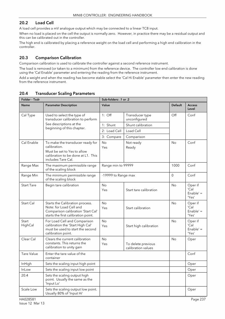
MINI8 CONTROLLER: ENGINEERING HANDBOOK
HA028581 Page 237 Issue 12 Mar 13
20.2 Load Cell A load cell provides a mV analogue output which may be connected to a linear TC8 input.
When no load is placed on the cell the output is normally zero. However, in practice there may be a residual output and this can be calibrated out in the controller.
The high end is calibrated by placing a reference weight on the load cell and performing a high end calibration in the controller.
20.3 Comparison Calibration Comparison calibration is used to calibrate the controller against a second reference instrument.
The load is removed (or taken to a minimum) from the reference device. The controller low end calibration is done using the ‘Cal Enable’ parameter and entering the reading from the reference instrument.
Add a weight and when the reading has become stable select the ‘Cal Hi Enable’ parameter then enter the new reading from the reference instrument.
20.4 Transducer Scaling Parameters Folder – Txdr Sub-folders: .1 or .2
Name
Parameter Description Value
Default Access Level
Cal Type Used to select the type of transducer calibration to perform See descriptions at the beginning of this chapter.
1: Off Transducer type unconfigured
Off Conf
1: Shunt Shunt calibration
2: Load Cell Load Cell
3: Compare Comparison
Cal Enable To make the transducer ready for calibration. Must be set to Yes to allow calibration to be done at L1. This includes Tare Cal.
No Yes
Not ready Ready
No Conf
Range Max The maximum permissible range of the scaling block
Range min to 99999 1000 Conf
Range Min The minimum permissible range of the scaling block
-19999 to Range max 0 Conf
Start Tare Begin tare calibration No Yes
Start tare calibration
No Oper if ‘Cal Enable’ = ‘Yes’
Start Cal Starts the Calibration process. Note: for Load Cell and Comparison calibration ‘Start Cal’ starts the first calibration point.
No Yes
Start calibration
No Oper if ‘Cal Enable’ = ‘Yes’
Start HighCal
For Load Cell and Comparison calibration the ‘Start High Cal’ must be used to start the second calibration point.
No Yes
Start high calibration
No Oper if ‘Cal Enable’ = ‘Yes’
Clear Cal Clears the current calibration constants. This returns the calibration to unity gain
No Yes
To delete previous calibration values
No Oper
Tare Value Enter the tare value of the container
Conf
InHigh Sets the scaling input high point Oper
InLow Sets the scaling input low point Oper
20.4 Sets the scaling output high point. Usually the same as the ‘Input Lo’
Oper
Scale Low Sets the scaling output low point. Usually 80% of ‘Input Hi’
Oper

MINI8 CONTROLLER: ENGINEERING HANDBOOK
Page 238 HA028581 Issue 12 Mar 13
Folder – Txdr Sub-folders: .1 or .2
Name
Parameter Description Value
Default Access Level
Cal Band The calibration algorithms use the threshold to determine if the value has settled. When switching in the shunt resistor, the algorithm waits for the value to settle to within the threshold before starting the high calibration point.
Conf
CalAdjust The adjust is used in the Comparison Calibration method.
When edited, the Adjust parameter can be set to the desired value. On confirm, the new adjust value is used to set the scaling constants
Oper
ShuntOut Indicates when the internal shunt calibration resistor is switched in. Only appears if ‘Cal Type’ = ‘Shunt’
Off On
Resistor not switched in Resistor switched in
Oper
Cal Active Indicates calibration taking place Off On
Inactive Active
R/O
InVal The input value to be scaled. -9999.9 to 9999.9 Oper
OutVal The Input Value is scaled by the block to produce the Output Value
Oper
Status The status of the output accounting for sensor fail signals passed to the block and the state of the scaling.
Good Bad
Conf
Cal Status Indicates the progress of calibration
0: Idle 1: Active 2: Passed 3: Failed
No calibration in progress Calibration in progress Calibration Passed Calibration Failed
L1 R/O

MINI8 CONTROLLER: ENGINEERING HANDBOOK
HA028581 Page 239 Issue 12 Mar 13
20.4.1 Parameter Notes
Enable Cal This may be wired to a digital input for an external switch. If not wired, then the value may be changed. When enabled the transducer parameters may be altered as described in the previous sections. When the parameter has been turned On it will remain on until turned off manually even if the controller is powered cycled.
Start Tare This may be wired to a digital input for an external switch. If not wired, then the value may be changed.
Start Cal This may be wired to a digital input for an external switch. If not wired, then the value may be changed. It starts the calibration procedure for: Shunt Calibration The low point for Load Cell Calibration The low point for Comparison Calibration
Start Hi Cal This may be wired to a digital input for an external switch. If not wired, then the value may be changed. It starts:- The high point for Load Cell Calibration The high point for Comparison Calibration
Clear Cal This may be wired to a digital input for an external switch. If not wired, then the value may be changed. When enabled the input will reset to default values. A new calibration will overwrite the previous calibration values if Clear Cal is not enabled between calibrations.
20.4.2 Tare Calibration The Mini8 controller has an auto-tare function that is used, for example, when it is required to weigh the contents of a container but not the container itself.
The procedure is to place the empty container on the weighbridge and ‘zero’ the controller. The procedure is as follows:-
1. Place container on weighbridge
2. Go to Txdr.1 (or .2) Folder.
3. Transducer calibration Type must be ‘Load Cell’.
4. CalEnable must be set to ‘Yes’.
5. Set StartTare to ‘yes’
6. The controller automatically calibrates the to the tare weight which is measured by the transducer and stores this value.
7. During this measurement Cal Status will show progress. If the cal fails it is probably an ‘out of range’ problem.

MINI8 CONTROLLER: ENGINEERING HANDBOOK
Page 240 HA028581 Issue 12 Mar 13
20.4.3 Load Cell A load cell output must be within the range 0 to 77 mV to go into a TC8 input. Use a shunt for mA inputs, mV can possibly go direct, Volt inputs must use a potential divider.
To calibrate a load cell.
1. Remove all load from the transducer to establish a zero reference.
2. Go to Txdr.1 (or .2) Folder.
3. Transducer calibration Type must be ‘Load Cell’.
4. CalEnable must be set to ‘Yes’.
5. Set Start Cal to ‘yes’
6. The controller will calibrate the low point.
7. Set StartHighCal to ‘yes’
8. The controller will calibrate the high point.
Cal Status advises progress and result.
20.4.4 Comparison Calibration Comparison calibration is used to calibrate the input against a second reference instrument. Typically this might be a local display on the weighing device itself.
To calibrate against a known reference source:-
1. Add a load at the low end of the scale range
2. Go to Txdr.1 (or .2) Folder.
3. Transducer calibration Type must be ‘Comparision’.
4. CalEnable must be set to ‘Yes’.
5. Enter the reading from the reference instrument into ‘Cal Adjust’.
6. Add a load at the high end of the scale.
7. Set StartHighCal to ‘yes’
8. The controller will calibrate the high point.
Cal Status advises progress and result.

MINI8 CONTROLLER: ENGINEERING HANDBOOK
HA028581 Page 241 Issue 12 Mar 13
21. Chapter 21 User Values User values are registers provided for use in calculations. They may be used as constants in equations or temporary storage in extended calculations. Up to 32 User Values are available. They are arranged in 4 groups of 8. Each User Value can then be set up in the ‘UserVal’ folder.
21.1 User Value Parameters Folder – UsrVal Sub-Folders: .1 to .32
Name
Parameter Description Value
Default Access Level
Units Units assigned to the User Value
None Abs Temp oC/oF/oK, V, mV, A, mA, PH, mmHg, psi, Bar, mBar, %RH, %, mmWG, inWG, inWW, Ohms, PSIG, %O2, PPM, %CO2, %CP, %/sec, RelTemp oC\oF\oK(rel), Custom 1, Custom 2, Custom 3, Custom 4, Custom 5, Custom 6, sec, min, hrs,
Conf
Resolution Resolution of the User Value XXXXX to X.XXXX Conf
High Limit The high limit may be set for each user value to prevent the value being set to an out-of-bounds value.
Oper
Low Limit The low limit of the user value may be set to prevent the user value from being edited to an illegal value. This is important if the user value is to be used as a setpoint.
Oper
Val To set the value within the range limits
See note 1 Oper
Status Can be used to force a good or bad status onto a user value. This is useful for testing status inheritance and fallback strategies.
Good Bad
See note 1 Oper
Note 1.
If ‘Val’ is wired into but ‘Status’ is not, then, instead of being used to force the Status it will indicate the status of the value as inherited form the wired connection to ‘Val’.

MINI8 CONTROLLER: ENGINEERING HANDBOOK
Page 242 HA028581 Issue 12 Mar 13
22. Chapter 22 Calibration In this chapter calibration refers to calibration of the inputs of the TC4 / TC8 modules and the RT4 module. Calibration is accessed using the ‘Cal State’ parameter that is only available in configuration level. Since the controller is calibrated during manufacture to traceable standards for every input range, it is not necessary to calibrate the controller when changing ranges. Furthermore, a continuous automatic check and correction of the calibration during the controllers’ normal operation means that it is calibrated for life. However, it is recognised that, for operational reasons, it may be a requirement to check or re-calibrate the controller. This new calibration is saved as a User Calibration. It is always possible to revert to the factory calibration if necessary.
☺ Tip: Consider using the ‘Offset’ parameter for User Cal (e.g. Mod.1.Offset). This can be set to correct any measured difference between the Mini8 controller given PV and a calibration value obtained from another source. This is useful where the process setpoint remains at about the same value during use.
Alternatively, if the setpoint range is wide use the two point calibration with the ‘LoPoint’, ‘LoOffset’, and ‘HiPoint’, ‘HiOffset’ parameters.
22.1 TC4 / TC8 User calibration 22.1.1 Set Up No pre-calibration warm-up is required. As calibration is a single-point on 8 channels, quick enough (a few minutes) to avoid self-heating effects, there are no special environmental, mounting position or ventilation requirements for calibration. Calibration should be performed at a reasonable ambient temperature (15oC to 35oC). Calibration outside these limits will compromise the expected working accuracy. Every channel of every TC8 card must be individually connected to the calibrator source using thick copper wire (so the sensor-break voltage drop in the wires and source impedance is minimal). The voltage source, monitor DVM and the target Mini8 controller should be at the same temperature (to eliminate added series e.m.f. due to thermocouple effects). The Mini8 controller must be in Configuration Mode.
22.1.2 Zero Calibration No “zero” calibration point is required for TC4/TC8 input channels
22.1.3 Voltage Calibration 1. Set the Calibrator voltage source to an accurate 50.005mV. (The extra 5uV is to compensate for self-
heating tempco effect). 2. Connect the 50mV to channel 1 3. Set Mod.1.CalState to HiCal (23) and then select ‘Confirm’ 4. When complete set CalState to SaveUser(25)
Exit configuration mode.
22.1.4 CJC Calibration
No CJC calibration required; the sampled values are ratio metric, providing uncalibrated uncertainty of ±1oC.
22.1.5 Sensor-Break Limit Check
Apply a 900Ω resistor to each channel in turn, Sensor Break Type to ‘Low’, filter to off (0). Verify the SBrkValue is greater than 24.0 and less than 61.0

MINI8 CONTROLLER: ENGINEERING HANDBOOK
HA028581 Page 243 Issue 12 Mar 13
22.2 To Return to TC4/TC8 Factory Calibration To clear the User calibration and restore the calibration from the factory.
1. Put Mini8 controller into Configuration Mode
2. Set the ‘Mod.1.Calibration State’ to LoadFact (24).
3. Return Instrument to Operating Mode.
22.3 RT4 User calibration 22.3.1 Set Up No pre-calibration warm-up is required. There are no special environmental, mounting position or ventilation requirements for calibration. Calibration should be performed at a reasonable ambient temperature (15oC to 35oC). Calibration outside these limits will compromise the expected working accuracy. Each channel of the RT4 card must be individually connected to the calibrated resistance box using the 4 wire connection. The Mini8 controller must be in Configuration Mode.
22.3.2 Calibration 1. Wire the resistance box to channel 1 using the four wire connection. 2. Set the Resistance box to 150.0 ohms ±0.02%. 3. Set Mod.1.CalState to LoCal (42) and then select ‘Confirm’ 4. When complete set CalState to SaveUser(45) 5. Set the Resistance box to 400.0 ohms ±0.02%. 6. Set Mod.1.CalState to HiCal (43) and then select ‘Confirm’ 7. When complete set CalState to SaveUser(45)
Exit configuration mode.
22.4 To Return to RT4 Factory Calibration To clear the User calibration and restore the calibration from the factory.
4. Put Mini8 controller into Configuration Mode
5. Set the ‘Mod.1.Calibration State’ to LoadFact (44).
6. Return Instrument to Operating Mode.

MINI8 CONTROLLER: ENGINEERING HANDBOOK
Page 244 HA028581 Issue 12 Mar 13
22.5 Calibration Parameters List Header - IO Sub-headers: Mod.1 to Mod.32
Name
Parameter Description
Value
Default Access Level
Cal State Calibration state of the input
Idle Normal operation Idle Conf Hi-50mV High input calibration for mV ranges
Load Fact Restore factory calibration values
Save User Save the new calibration values
Confirm To start the calibration procedure when one of the above has been selected
Go Starting the automatic calibration procedure
Busy Calibration in progress
Passed Calibration successful
Failed Calibration unsuccessful
Status PV Status The current status of the PV.
0 Normal operation R/O
1 Initial startup mode
2 Input in sensor break
3 PV outside operating limits
4 Saturated input
5 Uncalibrated channel
6 No Module
The above list shows the values of CalState, which appear during a normal calibration procedure. The full list of possible values follows – the number is the enumeration for the parameter.
1: Idle 35: User calibration stored
2: Low calibration point for Volts range 36: Factory calibration stored
3: High calibration point for Volts range 41: Idle
4: Calibration restored to factory default values 42: Low calibration point for RTD calibration (150 ohms)
5: User calibration stored 43: Low calibration point for RTD calibration (400 ohms)
6: Factory calibration stored 44: Calibration restored to factory default values
11: Idle 45: User calibration stored
12: Low calibration point for HZ input 46: Factory calibration stored
13: High calibration point for the HZ input 51: Idle
14: Calibration restored to factory default values 52: CJC calibration used in conjunction with Term Temp parameter
15: User calibration stored 54: Calibration restored to factory default values
16: Factory calibration stored 55: User calibration stored
20: Calibration point for factory rough calibration 56: Factory calibration stored
21: Idle 200: Confirmation of request to calibrate
22: Low calibration point for the mV range 201: Used to start the calibration procedure
23: Hi calibration point for the mV range 202: Used to abort the calibration procedure
24: Calibration restored to factory default values 210: Calibration point for factory rough calibration
25: User calibration stored 212: Indication that calibration is in progress
26: Factory calibration stored 213: Used to abort the calibration procedure
30: Calibration point for factory rough calibration 220: Indication that calibration completed successfully
31: Idle 221: Calibration accepted but not stored
32: Low calibration point for the mV range 222: Used to abort the calibration procedure
33: High calibration point for the mV range 223: Indication that calibration failed
34: Calibration restored to factory default values
MINI8 CONTROLLER: ENGINEERING HANDBOOK
HA028581 Page 245 Issue 12 Mar 13
23. Chapter 23 OEM Security 23.1 Introduction OEM security allows users, typically OEMs or distributors, to be able to protect their intellectual property by preventing unauthorised cloning of controller configurations.
OEM security is only available as a special order and is identified by special number EU0725 which appears on the label showing the order code.
The feature provides the user with the ability to enter an OEM Security Password, after which, unless the password is entered, it inhibits iTools from communicating with the controller in its normal way.
Notes:
1. It will still be possible to access communication parameters via the SCADA table.
2. If features such as OPC Scope are required then Custom Tags may be used to access the SCADA area.
23.2 Using OEM Security The OEM Security feature enables three new addresses to become active in the SCADA region. These are:-
1. Address 16116, ‘Locked’: this is a read only Boolean parameter that returns 1 (TRUE) when the instrument is OEM secured.
2. Address 16117, ‘Lock Code’: this is a write only parameter which will read back as 0. When the instrument is unlocked, a value entered here will lock the instrument and defines the code needed to unlock. The code and locked status will be saved in non-volatile memory.
3. Address 16118, ‘Unlock Code’: this is a write only parameter which will read back as 0. When the instrument is locked, a value entered here will be compared with the lock code. If it is the same, the instrument will be unlocked. If the value is different, this parameter will become unavailable for a time period. This time will increase for each failed attempt.
These addresses are not available by default in iTools. It is, therefore, necessary to create Custom Tags in iTools to be able to write or read these parameters. The following procedure shows how to do this and how to use the OEM security features.

MINI8 CONTROLLER: ENGINEERING HANDBOOK
Page 246 HA028581 Issue 12 Mar 13
23.3 Step 1 – View iTools OPC Server With iTools open and connected to the target instrument open the iTools OPC server using Options>Advanced>Show Server.
Click on the OPC Server application on your windows Taskbar to view the server.
ID001-Mini8

MINI8 CONTROLLER: ENGINEERING HANDBOOK
HA028581 Page 247 Issue 12 Mar 13
23.4 Step 2 – Create Custom Tags Expand the connected instrument to show all folders. Close to the bottom of the tree you will find a folder called CustTags.
Click on CustTags then click on the Tag icon on the Toolbar. Enter the name of the Tag as ‘Locked’ and its address as 16116 then press OK. Repeat for the ‘Lock’ and ‘Unlock Code’ addresses
Mini8
Tag Icon
CustTags Folder
Mini8

MINI8 CONTROLLER: ENGINEERING HANDBOOK
Page 248 HA028581 Issue 12 Mar 13
When all three Tags are created you will see the following:-
Minimise (do not close) the OPC server to the taskbar and return to iTools. You can now select CustTags on the connected instrument by double clicking on the folder when in the browse tab.
Mini8
COM1.ID001-Mini8
Mini8 v.2.3
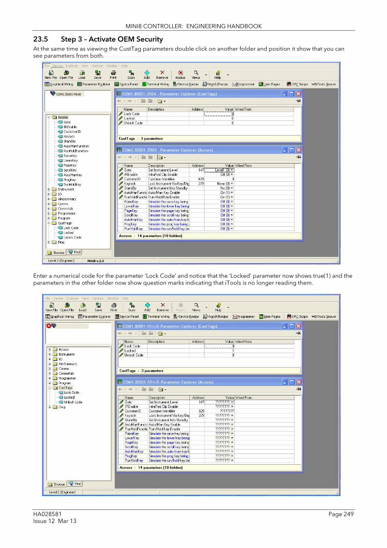
MINI8 CONTROLLER: ENGINEERING HANDBOOK
HA028581 Page 249 Issue 12 Mar 13
23.5 Step 3 – Activate OEM Security At the same time as viewing the CustTag parameters double click on another folder and position it show that you can see parameters from both.
Enter a numerical code for the parameter ‘Lock Code’ and notice that the ‘Locked’ parameter now shows true(1) and the parameters in the other folder now show question marks indicating that iTools is no longer reading them.
COM1.ID001-Mini8
Mini8 v.2.3
Mini8
Mini8

MINI8 CONTROLLER: ENGINEERING HANDBOOK
Page 250 HA028581 Issue 12 Mar 13
23.6 Step 4 – Deactivate OEM Security Enter the code you used in step 3 into ‘Unlock Code’ to enable full iTools communication.
If an incorrect code is entered this parameter will become unavailable for a time period, indicated by a warning message ‘Failed to write data to device’. This time will increase for each failed attempt limited to 1 minute. If the correct code is entered while the time delay is in operation it will not be accepted. It will be necessary to wait until the time delay is no longer operative (up to 1 minute) or to power cycle the controller.
23.7 Erasing Memory Since the OEM Lock/Unlock code is retained in ‘normal’ non-volatile memory, it may be erased by use of the Access.ClearMemory (Cold Start) parameter. Using this parameter to erase AllMemory will not only unlock the OEM Security but it will also erase the application being protected.
Note that the instrument must be in Config mode to accept the ClearMemory command. This process may also be done via the SCADA area. The Instrument Mode parameter is already in the SCADA area at address 199 - write a value of 2 to set Config mode. The Clear Memory parameter will be found at address 16119. Set a value of 5 (AllMemory) to clear the memory.

MINI8 CONTROLLER: ENGINEERING HANDBOOK
HA028581 Page 251 Issue 12 Mar 13
24. Appendix A MODBUS SCADA TABLE These parameters are single register Modbus values for use with Third Party Modbus masters in SCADA packages or plcs. Scaling of the parameters has to be configured – the Modbus master scaling has to match the Mini8 controller parameter resolution to ensure the decimal point is in the correct position. If a parameter has no address the CommsTab feature can be used to map the parameter to a modbus address, however, it should be noted that the address field will not be updated.
24.1 Comms Table The tables that follow do not include every parameter in the Mini8 controller. The Comms Table is used to make most parameters available at any SCADA address.
Folder – Commstab Sub-folders: .1 to .250
Name
Parameter Description Value
Default Access Level
Destination Modbus Destination Not Used 0 to 16064
Not used
Conf
Source Source Parameter Taken from source parameter Conf
Native Native Data Format 0 Integer 1 Native (i.e. Float or long)
Integer Conf
ReadOnly Read Only Read/Write only if source is R/W
0 Read/Write 1 Read Only
R/W Conf
Minutes Minutes Units in which time is scaled.
0 Seconds 1 Minutes
Seconds.
Conf
Entering a value in the Source parameter may be done in two ways:
1 - drag the required parameter into the Source
2 - right click the Source parameter, select Edit Wire and browse to the required parameter.
In the Example below the PV of Loop 1 would be available at addresses 200 and 201 as a two register floating point number - its native data type.
There are 250 comms table entries available.
24.2 SCADA Table The parameters in the tables following are available in scaled integer format, accessed via their associated Modbus address.
Wherever possible use an OPC client with the iTools OPCserver as the server. In this arrangement the parameters are all referenced by name and the values are floating point so the decimal point for all parameters is inherited.

MINI8 CONTROLLER: ENGINEERING HANDBOOK
Page 252 HA028581 Issue 12 Mar 13
Parameter Description / Modbus address DEC HEX
Access.CustomerID 4739 0x1283
Access.InstrumentMode 199 0x00c7
Alarm.1.Ack 10250 0x280a
Alarm.1.Block 10246 0x2806
Alarm.1.Delay 10248 0x2808
Alarm.1.Hysteresis 10242 0x2802
Alarm.1.Inhibit 10247 0x2807
Alarm.1.Latch 10244 0x2804
Alarm.1.Out 10249 0x2809
Alarm.1.Reference 10243 0x2803
Alarm.1.Threshold 10241 0x2801
Alarm.1.Type 10240 0x2800
Alarm.2.Ack 10266 0x281a
Alarm.2.Block 10262 0x2816
Alarm.2.Delay 10264 0x2818
Alarm.2.Hysteresis 10258 0x2812
Alarm.2.Inhibit 10263 0x2817
Alarm.2.Latch 10260 0x2814
Alarm.2.Out 10265 0x2819
Alarm.2.Reference 10259 0x2813
Alarm.2.Threshold 10257 0x2811
Alarm.2.Type 10256 0x2810
Alarm.3.Ack 10282 0x282a
Alarm.3.Block 10278 0x2826
Alarm.3.Delay 10280 0x2828
Alarm.3.Hysteresis 10274 0x2822
Alarm.3.Inhibit 10279 0x2827
Alarm.3.Latch 10276 0x2824
Alarm.3.Out 10281 0x2829
Alarm.3.Reference 10275 0x2823
Alarm.3.Threshold 10273 0x2821
Alarm.3.Type 10272 0x2820
Alarm.4.Ack 10298 0x283a
Alarm.4.Block 10294 0x2836
Alarm.4.Delay 10296 0x2838
Alarm.4.Hysteresis 10290 0x2832
Alarm.4.Inhibit 10295 0x2837
Alarm.4.Latch 10292 0x2834
Alarm.4.Out 10297 0x2839
Alarm.4.Reference 10291 0x2833
Alarm.4.Threshold 10289 0x2831
Alarm.4.Type 10288 0x2830
Alarm.5.Ack 10314 0x284a
Alarm.5.Block 10310 0x2846
Alarm.5.Delay 10312 0x2848
Alarm.5.Hysteresis 10306 0x2842
Alarm.5.Inhibit 10311 0x2847
Alarm.5.Latch 10308 0x2844
Alarm.5.Out 10313 0x2849
Alarm.5.Reference 10307 0x2843
Alarm.5.Threshold 10305 0x2841
Alarm.5.Type 10304 0x2840
Alarm.6.Ack 10330 0x285a
Alarm.6.Block 10326 0x2856
Alarm.6.Delay 10328 0x2858
Alarm.6.Hysteresis 10322 0x2852
Parameter Description / Modbus address DEC HEX
Alarm.6.Inhibit 10327 0x2857
Alarm.6.Latch 10324 0x2854
Alarm.6.Out 10329 0x2859
Alarm.6.Reference 10323 0x2853
Alarm.6.Threshold 10321 0x2851
Alarm.6.Type 10320 0x2850
Alarm.7.Ack 10346 0x286a
Alarm.7.Block 10342 0x2866
Alarm.7.Delay 10344 0x2868
Alarm.7.Hysteresis 10338 0x2862
Alarm.7.Inhibit 10343 0x2867
Alarm.7.Latch 10340 0x2864
Alarm.7.Out 10345 0x2869
Alarm.7.Reference 10339 0x2863
Alarm.7.Threshold 10337 0x2861
Alarm.7.Type 10336 0x2860
Alarm.8.Ack 10362 0x287a
Alarm.8.Block 10358 0x2876
Alarm.8.Delay 10360 0x2878
Alarm.8.Hysteresis 10354 0x2872
Alarm.8.Inhibit 10359 0x2877
Alarm.8.Latch 10356 0x2874
Alarm.8.Out 10361 0x2879
Alarm.8.Reference 10355 0x2873
Alarm.8.Threshold 10353 0x2871
Alarm.8.Type 10352 0x2870
Alarm.9.Ack 10378 0x288a
Alarm.9.Block 10374 0x2886
Alarm.9.Delay 10376 0x2888
Alarm.9.Hysteresis 10370 0x2882
Alarm.9.Inhibit 10375 0x2887
Alarm.9.Latch 10372 0x2884
Alarm.9.Out 10377 0x2889
Alarm.9.Reference 10371 0x2883
Alarm.9.Threshold 10369 0x2881
Alarm.9.Type 10368 0x2880
Alarm.10.Ack 10394 0x289a
Alarm.10.Block 10390 0x2896
Alarm.10.Delay 10392 0x2898
Alarm.10.Hysteresis 10386 0x2892
Alarm.10.Inhibit 10391 0x2897
Alarm.10.Latch 10388 0x2894
Alarm.10.Out 10393 0x2899
Alarm.10.Reference 10387 0x2893
Alarm.10.Threshold 10385 0x2891
Alarm.10.Type 10384 0x2890
Alarm.11.Ack 10410 0x28aa
Alarm.11.Block 10406 0x28a6
Alarm.11.Delay 10408 0x28a8
Alarm.11.Hysteresis 10402 0x28a2
Alarm.11.Inhibit 10407 0x28a7
Alarm.11.Latch 10404 0x28a4
Alarm.11.Out 10409 0x28a9
Alarm.11.Reference 10403 0x28a3
Alarm.11.Threshold 10401 0x28a1
Alarm.11.Type 10400 0x28a0

MINI8 CONTROLLER: ENGINEERING HANDBOOK
HA028581 Page 253 Issue 12 Mar 13
Parameter Description / Modbus address DEC HEX
Alarm.12.Ack 10426 0x28ba
Alarm.12.Block 10422 0x28b6
Alarm.12.Delay 10424 0x28b8
Alarm.12.Hysteresis 10418 0x28b2
Alarm.12.Inhibit 10423 0x28b7
Alarm.12.Latch 10420 0x28b4
Alarm.12.Out 10425 0x28b9
Alarm.12.Reference 10419 0x28b3
Alarm.12.Threshold 10417 0x28b1
Alarm.12.Type 10416 0x28b0
Alarm.13.Ack 10442 0x28ca
Alarm.13.Block 10438 0x28c6
Alarm.13.Delay 10440 0x28c8
Alarm.13.Hysteresis 10434 0x28c2
Alarm.13.Inhibit 10439 0x28c7
Alarm.13.Latch 10436 0x28c4
Alarm.13.Out 10441 0x28c9
Alarm.13.Reference 10435 0x28c3
Alarm.13.Threshold 10433 0x28c1
Alarm.13.Type 10432 0x28c0
Alarm.14.Ack 10458 0x28da
Alarm.14.Block 10454 0x28d6
Alarm.14.Delay 10456 0x28d8
Alarm.14.Hysteresis 10450 0x28d2
Alarm.14.Inhibit 10455 0x28d7
Alarm.14.Latch 10452 0x28d4
Alarm.14.Out 10457 0x28d9
Alarm.14.Reference 10451 0x28d3
Alarm.14.Threshold 10449 0x28d1
Alarm.14.Type 10448 0x28d0
Alarm.15.Ack 10474 0x28ea
Alarm.15.Block 10470 0x28e6
Alarm.15.Delay 10472 0x28e8
Alarm.15.Hysteresis 10466 0x28e2
Alarm.15.Inhibit 10471 0x28e7
Alarm.15.Latch 10468 0x28e4
Alarm.15.Out 10473 0x28e9
Alarm.15.Reference 10467 0x28e3
Alarm.15.Threshold 10465 0x28e1
Alarm.15.Type 10464 0x28e0
Alarm.16.Ack 10490 0x28fa
Alarm.16.Block 10486 0x28f6
Alarm.16.Delay 10488 0x28f8
Alarm.16.Hysteresis 10482 0x28f2
Alarm.16.Inhibit 10487 0x28f7
Alarm.16.Latch 10484 0x28f4
Alarm.16.Out 10489 0x28f9
Alarm.16.Reference 10483 0x28f3
Alarm.16.Threshold 10481 0x28f1
Alarm.16.Type 10480 0x28f0
Alarm.17.Ack 10506 0x290a
Alarm.17.Block 10502 0x2906
Alarm.17.Delay 10504 0x2908
Alarm.17.Hysteresis 10498 0x2902
Alarm.17.Inhibit 10503 0x2907
Parameter Description / Modbus address DEC HEX
Alarm.17.Latch 10500 0x2904
Alarm.17.Out 10505 0x2909
Alarm.17.Reference 10499 0x2903
Alarm.17.Threshold 10497 0x2901
Alarm.17.Type 10496 0x2900
Alarm.18.Ack 10522 0x291a
Alarm.18.Block 10518 0x2916
Alarm.18.Delay 10520 0x2918
Alarm.18.Hysteresis 10514 0x2912
Alarm.18.Inhibit 10519 0x2917
Alarm.18.Latch 10516 0x2914
Alarm.18.Out 10521 0x2919
Alarm.18.Reference 10515 0x2913
Alarm.18.Threshold 10513 0x2911
Alarm.18.Type 10512 0x2910
Alarm.19.Ack 10538 0x292a
Alarm.19.Block 10534 0x2926
Alarm.19.Delay 10536 0x2928
Alarm.19.Hysteresis 10530 0x2922
Alarm.19.Inhibit 10535 0x2927
Alarm.19.Latch 10532 0x2924
Alarm.19.Out 10537 0x2929
Alarm.19.Reference 10531 0x2923
Alarm.19.Threshold 10529 0x2921
Alarm.19.Type 10528 0x2920
Alarm.20.Ack 10554 0x293a
Alarm.20.Block 10550 0x2936
Alarm.20.Delay 10552 0x2938
Alarm.20.Hysteresis 10546 0x2932
Alarm.20.Inhibit 10551 0x2937
Alarm.20.Latch 10548 0x2934
Alarm.20.Out 10553 0x2939
Alarm.20.Reference 10547 0x2933
Alarm.20.Threshold 10545 0x2931
Alarm.20.Type 10544 0x2930
Alarm.21.Ack 10570 0x294a
Alarm.21.Block 10566 0x2946
Alarm.21.Delay 10568 0x2948
Alarm.21.Hysteresis 10562 0x2942
Alarm.21.Inhibit 10567 0x2947
Alarm.21.Latch 10564 0x2944
Alarm.21.Out 10569 0x2949
Alarm.21.Reference 10563 0x2943
Alarm.21.Threshold 10561 0x2941
Alarm.21.Type 10560 0x2940
Alarm.22.Ack 10586 0x295a
Alarm.22.Block 10582 0x2956
Alarm.22.Delay 10584 0x2958
Alarm.22.Hysteresis 10578 0x2952
Alarm.22.Inhibit 10583 0x2957
Alarm.22.Latch 10580 0x2954
Alarm.22.Out 10585 0x2959
Alarm.22.Reference 10579 0x2953
Alarm.22.Threshold 10577 0x2951
Alarm.22.Type 10576 0x2950

MINI8 CONTROLLER: ENGINEERING HANDBOOK
Page 254 HA028581 Issue 12 Mar 13
Parameter Description / Modbus address DEC HEX
Alarm.23.Ack 10602 0x296a
Alarm.23.Block 10598 0x2966
Alarm.23.Delay 10600 0x2968
Alarm.23.Hysteresis 10594 0x2962
Alarm.23.Inhibit 10599 0x2967
Alarm.23.Latch 10596 0x2964
Alarm.23.Out 10601 0x2969
Alarm.23.Reference 10595 0x2963
Alarm.23.Threshold 10593 0x2961
Alarm.23.Type 10592 0x2960
Alarm.24.Ack 10618 0x297a
Alarm.24.Block 10614 0x2976
Alarm.24.Delay 10616 0x2978
Alarm.24.Hysteresis 10610 0x2972
Alarm.24.Inhibit 10615 0x2977
Alarm.24.Latch 10612 0x2974
Alarm.24.Out 10617 0x2979
Alarm.24.Reference 10611 0x2973
Alarm.24.Threshold 10609 0x2971
Alarm.24.Type 10608 0x2970
Alarm.25.Ack 10634 0x298a
Alarm.25.Block 10630 0x2986
Alarm.25.Delay 10632 0x2988
Alarm.25.Hysteresis 10626 0x2982
Alarm.25.Inhibit 10631 0x2987
Alarm.25.Latch 10628 0x2984
Alarm.25.Out 10633 0x2989
Alarm.25.Reference 10627 0x2983
Alarm.25.Threshold 10625 0x2981
Alarm.25.Type 10624 0x2980
Alarm.26.Ack 10650 0x299a
Alarm.26.Block 10646 0x2996
Alarm.26.Delay 10648 0x2998
Alarm.26.Hysteresis 10642 0x2992
Alarm.26.Inhibit 10647 0x2997
Alarm.26.Latch 10644 0x2994
Alarm.26.Out 10649 0x2999
Alarm.26.Reference 10643 0x2993
Alarm.26.Threshold 10641 0x2991
Alarm.26.Type 10640 0x2990
Alarm.27.Ack 10666 0x29aa
Alarm.27.Block 10662 0x29a6
Alarm.27.Delay 10664 0x29a8
Alarm.27.Hysteresis 10658 0x29a2
Alarm.27.Inhibit 10663 0x29a7
Alarm.27.Latch 10660 0x29a4
Alarm.27.Out 10665 0x29a9
Alarm.27.Reference 10659 0x29a3
Alarm.27.Threshold 10657 0x29a1
Alarm.27.Type 10656 0x29a0
Alarm.28.Ack 10682 0x29ba
Alarm.28.Block 10678 0x29b6
Alarm.28.Delay 10680 0x29b8
Alarm.28.Hysteresis 10674 0x29b2
Alarm.28.Inhibit 10679 0x29b7
Alarm.28.Latch 10676 0x29b4
Parameter Description / Modbus address DEC HEX
Alarm.28.Out 10681 0x29b9
Alarm.28.Reference 10675 0x29b3
Alarm.28.Threshold 10673 0x29b1
Alarm.28.Type 10672 0x29b0
Alarm.29.Ack 10698 0x29ca
Alarm.29.Block 10694 0x29c6
Alarm.29.Delay 10696 0x29c8
Alarm.29.Hysteresis 10690 0x29c2
Alarm.29.Inhibit 10695 0x29c7
Alarm.29.Latch 10692 0x29c4
Alarm.29.Out 10697 0x29c9
Alarm.29.Reference 10691 0x29c3
Alarm.29.Threshold 10689 0x29c1
Alarm.29.Type 10688 0x29c0
Alarm.30.Ack 10714 0x29da
Alarm.30.Block 10710 0x29d6
Alarm.30.Delay 10712 0x29d8
Alarm.30.Hysteresis 10706 0x29d2
Alarm.30.Inhibit 10711 0x29d7
Alarm.30.Latch 10708 0x29d4
Alarm.30.Out 10713 0x29d9
Alarm.30.Reference 10707 0x29d3
Alarm.30.Threshold 10705 0x29d1
Alarm.30.Type 10704 0x29d0
Alarm.31.Ack 10730 0x29ea
Alarm.31.Block 10726 0x29e6
Alarm.31.Delay 10728 0x29e8
Alarm.31.Hysteresis 10722 0x29e2
Alarm.31.Inhibit 10727 0x29e7
Alarm.31.Latch 10724 0x29e4
Alarm.31.Out 10729 0x29e9
Alarm.31.Reference 10723 0x29e3
Alarm.31.Threshold 10721 0x29e1
Alarm.31.Type 10720 0x29e0
Alarm.32.Ack 10746 0x29fa
Alarm.32.Block 10742 0x29f6
Alarm.32.Delay 10744 0x29f8
Alarm.32.Hysteresis 10738 0x29f2
Alarm.32.Inhibit 10743 0x29f7
Alarm.32.Latch 10740 0x29f4
Alarm.32.Out 10745 0x29f9
Alarm.32.Reference 10739 0x29f3
Alarm.32.Threshold 10737 0x29f1
Alarm.32.Type 10736 0x29f0
AlmSummary.General.AnAlarmStatus1 10176 0x27c0
AlmSummary.General.AnAlarmStatus2 10177 0x27c1
AlmSummary.General.AnAlarmStatus3 10178 0x27c2
AlmSummary.General.AnAlarmStatus4 10179 0x27c3
AlmSummary.General.AnyAlarm 10213 0x27e5
AlmSummary.General.CTAlarmStatus1 4192 0x1060
AlmSummary.General.CTAlarmStatus2 4193 0x1061
AlmSummary.General.CTAlarmStatus3 4194 0x1062
AlmSummary.General.CTAlarmStatus4 4195 0x1063
AlmSummary.General.DigAlarmStatus1 10188 0x27cc
AlmSummary.General.DigAlarmStatus2 10189 0x27cd
AlmSummary.General.DigAlarmStatus3 10190 0x27ce

MINI8 CONTROLLER: ENGINEERING HANDBOOK
HA028581 Page 255 Issue 12 Mar 13
Parameter Description / Modbus address DEC HEX
AlmSummary.General.DigAlarmStatus4 10191 0x27cf
AlmSummary.General.GlobalAck 10214 0x27e6
AlmSummary.General.NewAlarm 10212 0x27e4
AlmSummary.General.NewCTAlarm 4196 0x1064
AlmSummary.General.RstNewAlarm 10215 0x27e7
AlmSummary.General.RstNewCTAlarm 4197 0x1065
AlmSummary.General.SBrkAlarmStatus1 10200 0x27d8
AlmSummary.General.SBrkAlarmStatus2 10201 0x27d9
AlmSummary.General.SBrkAlarmStatus3 10202 0x27da
AlmSummary.General.SBrkAlarmStatus4 10203 0x27db
BCDInput.1.BCDVal 5072 0x13d0
BCDInput.2.BCDVal 5073 0x13d1
Comms.FC.Ident 12963 0x32a3
DigAlarm.1.Ack 11274 0x2c0a
DigAlarm.1.Block 11270 0x2c06
DigAlarm.1.Delay 11272 0x2c08
DigAlarm.1.Inhibit 11271 0x2c07
DigAlarm.1.Latch 11268 0x2c04
DigAlarm.1.Out 11273 0x2c09
DigAlarm.1.Type 11264 0x2c00
DigAlarm.2.Ack 11290 0x2c1a
DigAlarm.2.Block 11286 0x2c16
DigAlarm.2.Delay 11288 0x2c18
DigAlarm.2.Inhibit 11287 0x2c17
DigAlarm.2.Latch 11284 0x2c14
DigAlarm.2.Out 11289 0x2c19
DigAlarm.2.Type 11280 0x2c10
DigAlarm.3.Ack 11306 0x2c2a
DigAlarm.3.Block 11302 0x2c26
DigAlarm.3.Delay 11304 0x2c28
DigAlarm.3.Inhibit 11303 0x2c27
DigAlarm.3.Latch 11300 0x2c24
DigAlarm.3.Out 11305 0x2c29
DigAlarm.3.Type 11296 0x2c20
DigAlarm.4.Ack 11322 0x2c3a
DigAlarm.4.Block 11318 0x2c36
DigAlarm.4.Delay 11320 0x2c38
DigAlarm.4.Inhibit 11319 0x2c37
DigAlarm.4.Latch 11316 0x2c34
DigAlarm.4.Out 11321 0x2c39
DigAlarm.4.Type 11312 0x2c30
DigAlarm.5.Ack 11338 0x2c4a
DigAlarm.5.Block 11334 0x2c46
DigAlarm.5.Delay 11336 0x2c48
DigAlarm.5.Inhibit 11335 0x2c47
DigAlarm.5.Latch 11332 0x2c44
DigAlarm.5.Out 11337 0x2c49
DigAlarm.5.Type 11328 0x2c40
DigAlarm.6.Ack 11354 0x2c5a
DigAlarm.6.Block 11350 0x2c56
DigAlarm.6.Delay 11352 0x2c58
DigAlarm.6.Inhibit 11351 0x2c57
DigAlarm.6.Latch 11348 0x2c54
DigAlarm.6.Out 11353 0x2c59
DigAlarm.6.Type 11344 0x2c50
Parameter Description / Modbus address DEC HEX
DigAlarm.7.Ack 11370 0x2c6a
DigAlarm.7.Block 11366 0x2c66
DigAlarm.7.Delay 11368 0x2c68
DigAlarm.7.Inhibit 11367 0x2c67
DigAlarm.7.Latch 11364 0x2c64
DigAlarm.7.Out 11369 0x2c69
DigAlarm.7.Type 11360 0x2c60
DigAlarm.8.Ack 11386 0x2c7a
DigAlarm.8.Block 11382 0x2c76
DigAlarm.8.Delay 11384 0x2c78
DigAlarm.8.Inhibit 11383 0x2c77
DigAlarm.8.Latch 11380 0x2c74
DigAlarm.8.Out 11385 0x2c79
DigAlarm.8.Type 11376 0x2c70
DigAlarm.9.Ack 11402 0x2c8a
DigAlarm.9.Block 11398 0x2c86
DigAlarm.9.Delay 11400 0x2c88
DigAlarm.9.Inhibit 11399 0x2c87
DigAlarm.9.Latch 11396 0x2c84
DigAlarm.9.Out 11401 0x2c89
DigAlarm.9.Type 11392 0x2c80
DigAlarm.10.Ack 11418 0x2c9a
DigAlarm.10.Block 11414 0x2c96
DigAlarm.10.Delay 11416 0x2c98
DigAlarm.10.Inhibit 11415 0x2c97
DigAlarm.10.Latch 11412 0x2c94
DigAlarm.10.Out 11417 0x2c99
DigAlarm.10.Type 11408 0x2c90
DigAlarm.11.Ack 11434 0x2caa
DigAlarm.11.Block 11430 0x2ca6
DigAlarm.11.Delay 11432 0x2ca8
DigAlarm.11.Inhibit 11431 0x2ca7
DigAlarm.11.Latch 11428 0x2ca4
DigAlarm.11.Out 11433 0x2ca9
DigAlarm.11.Type 11424 0x2ca0
DigAlarm.12.Ack 11450 0x2cba
DigAlarm.12.Block 11446 0x2cb6
DigAlarm.12.Delay 11448 0x2cb8
DigAlarm.12.Inhibit 11447 0x2cb7
DigAlarm.12.Latch 11444 0x2cb4
DigAlarm.12.Out 11449 0x2cb9
DigAlarm.12.Type 11440 0x2cb0
DigAlarm.13.Ack 11466 0x2cca
DigAlarm.13.Block 11462 0x2cc6
DigAlarm.13.Delay 11464 0x2cc8
DigAlarm.13.Inhibit 11463 0x2cc7
DigAlarm.13.Latch 11460 0x2cc4
DigAlarm.13.Out 11465 0x2cc9
DigAlarm.13.Type 11456 0x2cc0
DigAlarm.14.Ack 11482 0x2cda
DigAlarm.14.Block 11478 0x2cd6
DigAlarm.14.Delay 11480 0x2cd8
DigAlarm.14.Inhibit 11479 0x2cd7
DigAlarm.14.Latch 11476 0x2cd4
DigAlarm.14.Out 11481 0x2cd9

MINI8 CONTROLLER: ENGINEERING HANDBOOK
Page 256 HA028581 Issue 12 Mar 13
Parameter Description / Modbus address DEC HEX
DigAlarm.14.Type 11472 0x2cd0
DigAlarm.15.Ack 11498 0x2cea
DigAlarm.15.Block 11494 0x2ce6
DigAlarm.15.Delay 11496 0x2ce8
DigAlarm.15.Inhibit 11495 0x2ce7
DigAlarm.15.Latch 11492 0x2ce4
DigAlarm.15.Out 11497 0x2ce9
DigAlarm.15.Type 11488 0x2ce0
DigAlarm.16.Ack 11514 0x2cfa
DigAlarm.16.Block 11510 0x2cf6
DigAlarm.16.Delay 11512 0x2cf8
DigAlarm.16.Inhibit 11511 0x2cf7
DigAlarm.16.Latch 11508 0x2cf4
DigAlarm.16.Out 11513 0x2cf9
DigAlarm.16.Type 11504 0x2cf0
DigAlarm.17.Ack 11530 0x2d0a
DigAlarm.17.Block 11526 0x2d06
DigAlarm.17.Delay 11528 0x2d08
DigAlarm.17.Inhibit 11527 0x2d07
DigAlarm.17.Latch 11524 0x2d04
DigAlarm.17.Out 11529 0x2d09
DigAlarm.17.Type 11520 0x2d00
DigAlarm.18.Ack 11546 0x2d1a
DigAlarm.18.Block 11542 0x2d16
DigAlarm.18.Delay 11544 0x2d18
DigAlarm.18.Inhibit 11543 0x2d17
DigAlarm.18.Latch 11540 0x2d14
DigAlarm.18.Out 11545 0x2d19
DigAlarm.18.Type 11536 0x2d10
DigAlarm.19.Ack 11562 0x2d2a
DigAlarm.19.Block 11558 0x2d26
DigAlarm.19.Delay 11560 0x2d28
DigAlarm.19.Inhibit 11559 0x2d27
DigAlarm.19.Latch 11556 0x2d24
DigAlarm.19.Out 11561 0x2d29
DigAlarm.19.Type 11552 0x2d20
DigAlarm.20.Ack 11578 0x2d3a
DigAlarm.20.Block 11574 0x2d36
DigAlarm.20.Delay 11576 0x2d38
DigAlarm.20.Inhibit 11575 0x2d37
DigAlarm.20.Latch 11572 0x2d34
DigAlarm.20.Out 11577 0x2d39
DigAlarm.20.Type 11568 0x2d30
DigAlarm.21.Ack 11594 0x2d4a
DigAlarm.21.Block 11590 0x2d46
DigAlarm.21.Delay 11592 0x2d48
DigAlarm.21.Inhibit 11591 0x2d47
DigAlarm.21.Latch 11588 0x2d44
DigAlarm.21.Out 11593 0x2d49
DigAlarm.21.Type 11584 0x2d40
DigAlarm.22.Ack 11610 0x2d5a
DigAlarm.22.Block 11606 0x2d56
DigAlarm.22.Delay 11608 0x2d58
DigAlarm.22.Inhibit 11607 0x2d57
DigAlarm.22.Latch 11604 0x2d54
DigAlarm.22.Out 11609 0x2d59
Parameter Description / Modbus address DEC HEX
DigAlarm.22.Type 11600 0x2d50
DigAlarm.23.Ack 11626 0x2d6a
DigAlarm.23.Block 11622 0x2d66
DigAlarm.23.Delay 11624 0x2d68
DigAlarm.23.Inhibit 11623 0x2d67
DigAlarm.23.Latch 11620 0x2d64
DigAlarm.23.Out 11625 0x2d69
DigAlarm.23.Type 11616 0x2d60
DigAlarm.24.Ack 11642 0x2d7a
DigAlarm.24.Block 11638 0x2d76
DigAlarm.24.Delay 11640 0x2d78
DigAlarm.24.Inhibit 11639 0x2d77
DigAlarm.24.Latch 11636 0x2d74
DigAlarm.24.Out 11641 0x2d79
DigAlarm.24.Type 11632 0x2d70
DigAlarm.25.Ack 11658 0x2d8a
DigAlarm.25.Block 11654 0x2d86
DigAlarm.25.Delay 11656 0x2d88
DigAlarm.25.Inhibit 11655 0x2d87
DigAlarm.25.Latch 11652 0x2d84
DigAlarm.25.Out 11657 0x2d89
DigAlarm.25.Type 11648 0x2d80
DigAlarm.26.Ack 11674 0x2d9a
DigAlarm.26.Block 11670 0x2d96
DigAlarm.26.Delay 11672 0x2d98
DigAlarm.26.Inhibit 11671 0x2d97
DigAlarm.26.Latch 11668 0x2d94
DigAlarm.26.Out 11673 0x2d99
DigAlarm.26.Type 11664 0x2d90
DigAlarm.27.Ack 11690 0x2daa
DigAlarm.27.Block 11686 0x2da6
DigAlarm.27.Delay 11688 0x2da8
DigAlarm.27.Inhibit 11687 0x2da7
DigAlarm.27.Latch 11684 0x2da4
DigAlarm.27.Out 11689 0x2da9
DigAlarm.27.Type 11680 0x2da0
DigAlarm.28.Ack 11706 0x2dba
DigAlarm.28.Block 11702 0x2db6
DigAlarm.28.Delay 11704 0x2db8
DigAlarm.28.Inhibit 11703 0x2db7
DigAlarm.28.Latch 11700 0x2db4
DigAlarm.28.Out 11705 0x2db9
DigAlarm.28.Type 11696 0x2db0
DigAlarm.29.Ack 11722 0x2dca
DigAlarm.29.Block 11718 0x2dc6
DigAlarm.29.Delay 11720 0x2dc8
DigAlarm.29.Inhibit 11719 0x2dc7
DigAlarm.29.Latch 11716 0x2dc4
DigAlarm.29.Out 11721 0x2dc9
DigAlarm.29.Type 11712 0x2dc0
DigAlarm.30.Ack 11738 0x2dda
DigAlarm.30.Block 11734 0x2dd6
DigAlarm.30.Delay 11736 0x2dd8
DigAlarm.30.Inhibit 11735 0x2dd7
DigAlarm.30.Latch 11732 0x2dd4
DigAlarm.30.Out 11737 0x2dd9

MINI8 CONTROLLER: ENGINEERING HANDBOOK
HA028581 Page 257 Issue 12 Mar 13
Parameter Description / Modbus address DEC HEX
DigAlarm.30.Type 11728 0x2dd0
DigAlarm.31.Ack 11754 0x2dea
DigAlarm.31.Block 11750 0x2de6
DigAlarm.31.Delay 11752 0x2de8
DigAlarm.31.Inhibit 11751 0x2de7
DigAlarm.31.Latch 11748 0x2de4
DigAlarm.31.Out 11753 0x2de9
DigAlarm.31.Type 11744 0x2de0
DigAlarm.32.Ack 11770 0x2dfa
DigAlarm.32.Block 11766 0x2df6
DigAlarm.32.Delay 11768 0x2df8
DigAlarm.32.Inhibit 11767 0x2df7
DigAlarm.32.Latch 11764 0x2df4
DigAlarm.32.Out 11769 0x2df9
DigAlarm.32.Type 11760 0x2df0
Humidity.DewPoint 13317 0x3405
Humidity.DryTemp 13318 0x3406
Humidity.Pressure 13313 0x3401
Humidity.PsychroConst 13315 0x3403
Humidity.RelHumid 13316 0x3404
Humidity.Resolution 13320 0x3408
Humidity.SBrk 13314 0x3402
Humidity.WetOffset 13312 0x3400
Humidity.WetTemp 13319 0x3407
Instrument.Diagnostics.CntrlOverrun 4737 0x1281
Instrument.Diagnostics.ErrCount 4736 0x1280
Instrument.Diagnostics.PSUident 13027 0x32e3
Instrument.InstInfo.CompanyID 121 0x0079
Instrument.InstInfo.InstType 122 0x007a
Instrument.InstInfo.Version 107 0x006b
Instrument.Options.Units 4738 0x1282
IO.CurrentMonitor.Config.CalibrateCT1 4170 0x104a
IO.CurrentMonitor.Config.CalibrateCT2 4171 0x104b
IO.CurrentMonitor.Config.CalibrateCT3 4172 0x104c
IO.CurrentMonitor.Config.Commission 4096 0x1000
IO.CurrentMonitor.Config.CommissionStatus 4097 0x1001
IO.CurrentMonitor.Config.CT1Range 4103 0x1007
IO.CurrentMonitor.Config.CT1Resolution 4198 0x1066
IO.CurrentMonitor.Config.CT2Range 4104 0x1008
IO.CurrentMonitor.Config.CT2Resolution 4199 0x1067
IO.CurrentMonitor.Config.CT3Range 4105 0x1009
IO.CurrentMonitor.Config.CT3Resolution 4200 0x1068
IO.CurrentMonitor.Config.Inhibit 4099 0x1003
IO.CurrentMonitor.Config.Interval 4098 0x1002
IO.CurrentMonitor.Config.Load1CTInput 4107 0x100b
IO.CurrentMonitor.Config.Load1DrivenBy 4106 0x100a
IO.CurrentMonitor.Config.Load1OCFthreshold 4109 0x100d
IO.CurrentMonitor.Config.Load1PLFthreshold 4108 0x100c
IO.CurrentMonitor.Config.Load1Resolution 4201 0x1069
IO.CurrentMonitor.Config.Load2CTInput 4111 0x100f
IO.CurrentMonitor.Config.Load2DrivenBy 4110 0x100e
IO.CurrentMonitor.Config.Load2OCFthreshold 4113 0x1011
IO.CurrentMonitor.Config.Load2PLFthreshold 4112 0x1010
IO.CurrentMonitor.Config.Load2Resolution 4202 0x106a
IO.CurrentMonitor.Config.Load3CTInput 4115 0x1013
Parameter Description / Modbus address DEC HEX
IO.CurrentMonitor.Config.Load3DrivenBy 4114 0x1012
IO.CurrentMonitor.Config.Load3OCFthreshold 4117 0x1015
IO.CurrentMonitor.Config.Load3PLFthreshold 4116 0x1014
IO.CurrentMonitor.Config.Load3Resolution 4203 0x106b
IO.CurrentMonitor.Config.Load4CTInput 4119 0x1017
IO.CurrentMonitor.Config.Load4DrivenBy 4118 0x1016
IO.CurrentMonitor.Config.Load4OCFthreshold 4121 0x1019
IO.CurrentMonitor.Config.Load4PLFthreshold 4120 0x1018
IO.CurrentMonitor.Config.Load4Resolution 4204 0x106c
IO.CurrentMonitor.Config.Load5CTInput 4123 0x101b
IO.CurrentMonitor.Config.Load5DrivenBy 4122 0x101a
IO.CurrentMonitor.Config.Load5OCFthreshold 4125 0x101d
IO.CurrentMonitor.Config.Load5PLFthreshold 4124 0x101c
IO.CurrentMonitor.Config.Load5Resolution 4205 0x106d
IO.CurrentMonitor.Config.Load6CTInput 4127 0x101f
IO.CurrentMonitor.Config.Load6DrivenBy 4126 0x101e
IO.CurrentMonitor.Config.Load6OCFthreshold 4129 0x1021
IO.CurrentMonitor.Config.Load6PLFthreshold 4128 0x1020
IO.CurrentMonitor.Config.Load6Resolution 4206 0x106e
IO.CurrentMonitor.Config.Load7CTInput 4131 0x1023
IO.CurrentMonitor.Config.Load7DrivenBy 4130 0x1022
IO.CurrentMonitor.Config.Load7OCFthreshold 4133 0x1025
IO.CurrentMonitor.Config.Load7PLFthreshold 4132 0x1024
IO.CurrentMonitor.Config.Load7Resolution 4207 0x106f
IO.CurrentMonitor.Config.Load8CTInput 4135 0x1027
IO.CurrentMonitor.Config.Load8DrivenBy 4134 0x1026
IO.CurrentMonitor.Config.Load8OCFthreshold 4137 0x1029
IO.CurrentMonitor.Config.Load8PLFthreshold 4136 0x1028
IO.CurrentMonitor.Config.Load8Resolution 4208 0x1070
IO.CurrentMonitor.Config.Load9CTInput 4139 0x102b
IO.CurrentMonitor.Config.Load9DrivenBy 4138 0x102a
IO.CurrentMonitor.Config.Load9OCFthreshold 4141 0x102d
IO.CurrentMonitor.Config.Load9PLFthreshold 4140 0x102c
IO.CurrentMonitor.Config.Load9Resolution 4209 0x1071
IO.CurrentMonitor.Config.Load10CTInput 4143 0x102f
IO.CurrentMonitor.Config.Load10DrivenBy 4142 0x102e
IO.CurrentMonitor.Config.Load10OCFthreshold 4145 0x1031
IO.CurrentMonitor.Config.Load10PLFthreshold 4144 0x1030
IO.CurrentMonitor.Config.Load10Resolution 4210 0x1072
IO.CurrentMonitor.Config.Load11CTInput 4147 0x1033
IO.CurrentMonitor.Config.Load11DrivenBy 4146 0x1032
IO.CurrentMonitor.Config.Load11OCFthreshold 4149 0x1035
IO.CurrentMonitor.Config.Load11PLFthreshold 4148 0x1034
IO.CurrentMonitor.Config.Load11Resolution 4211 0x1073
IO.CurrentMonitor.Config.Load12CTInput 4151 0x1037
IO.CurrentMonitor.Config.Load12DrivenBy 4150 0x1036
IO.CurrentMonitor.Config.Load12OCFthreshold 4153 0x1039
IO.CurrentMonitor.Config.Load12PLFthreshold 4152 0x1038
IO.CurrentMonitor.Config.Load12Resolution 4212 0x1074
IO.CurrentMonitor.Config.Load13CTInput 4155 0x103b
IO.CurrentMonitor.Config.Load13DrivenBy 4154 0x103a
IO.CurrentMonitor.Config.Load13OCFthreshold 4157 0x103d
IO.CurrentMonitor.Config.Load13PLFthreshold 4156 0x103c
IO.CurrentMonitor.Config.Load13Resolution 4213 0x1075
IO.CurrentMonitor.Config.Load14CTInput 4159 0x103f

MINI8 CONTROLLER: ENGINEERING HANDBOOK
Page 258 HA028581 Issue 12 Mar 13
Parameter Description / Modbus address DEC HEX
IO.CurrentMonitor.Config.Load14DrivenBy 4158 0x103e
IO.CurrentMonitor.Config.Load14OCFthreshold 4161 0x1041
IO.CurrentMonitor.Config.Load14PLFthreshold 4160 0x1040
IO.CurrentMonitor.Config.Load14Resolution 4214 0x1076
IO.CurrentMonitor.Config.Load15CTInput 4163 0x1043
IO.CurrentMonitor.Config.Load15DrivenBy 4162 0x1042
IO.CurrentMonitor.Config.Load15OCFthreshold 4165 0x1045
IO.CurrentMonitor.Config.Load15PLFthreshold 4164 0x1044
IO.CurrentMonitor.Config.Load15Resolution 4215 0x1077
IO.CurrentMonitor.Config.Load16CTInput 4167 0x1047
IO.CurrentMonitor.Config.Load16DrivenBy 4166 0x1046
IO.CurrentMonitor.Config.Load16OCFthreshold 4169 0x1049
IO.CurrentMonitor.Config.Load16PLFthreshold 4168 0x1048
IO.CurrentMonitor.Config.Load16Resolution 4216 0x1078
IO.CurrentMonitor.Config.MaxLeakPh1 4100 0x1004
IO.CurrentMonitor.Config.MaxLeakPh2 4101 0x1005
IO.CurrentMonitor.Config.MaxLeakPh3 4102 0x1006
IO.CurrentMonitor.Status.Load1Current 4173 0x104d
IO.CurrentMonitor.Status.Load2Current 4174 0x104e
IO.CurrentMonitor.Status.Load3Current 4175 0x104f
IO.CurrentMonitor.Status.Load4Current 4176 0x1050
IO.CurrentMonitor.Status.Load5Current 4177 0x1051
IO.CurrentMonitor.Status.Load6Current 4178 0x1052
IO.CurrentMonitor.Status.Load7Current 4179 0x1053
IO.CurrentMonitor.Status.Load8Current 4180 0x1054
IO.CurrentMonitor.Status.Load9Current 4181 0x1055
IO.CurrentMonitor.Status.Load10Current 4182 0x1056
IO.CurrentMonitor.Status.Load11Current 4183 0x1057
IO.CurrentMonitor.Status.Load12Current 4184 0x1058
IO.CurrentMonitor.Status.Load13Current 4185 0x1059
IO.CurrentMonitor.Status.Load14Current 4186 0x105a
IO.CurrentMonitor.Status.Load15Current 4187 0x105b
IO.CurrentMonitor.Status.Load16Current 4188 0x105c
IO.CurrentMonitor.Status.Ph1AllOff 4189 0x105d
IO.CurrentMonitor.Status.Ph2AllOff 4190 0x105e
IO.CurrentMonitor.Status.Ph3AllOff 4191 0x105f
IO.FixedIO.A.PV 4226 0x1082
IO.FixedIO.B.PV 4227 0x1083
IO.FixedIO.D1.PV 4224 0x1080
IO.FixedIO.D2.PV 4225 0x1081
IO.Mod.1.AlarmAck 4260 0x10a4
IO.Mod.1.HiOffset 4420 0x1144
IO.Mod.1.HiPoint 4388 0x1124
IO.Mod.1.LoOffset 4356 0x1104
IO.Mod.1.LoPoint 4324 0x10e4
IO.Mod.1.MinOnTime 4292 0x10c4
IO.Mod.1.PV 4228 0x1084
IO.Mod.2.AlarmAck 4261 0x10a5
IO.Mod.2.HiOffset 4421 0x1145
IO.Mod.2.HiPoint 4389 0x1125
IO.Mod.2.LoOffset 4357 0x1105
IO.Mod.2.LoPoint 4325 0x10e5
IO.Mod.2.MinOnTime 4293 0x10c5
IO.Mod.2.PV 4229 0x1085
IO.Mod.3.AlarmAck 4262 0x10a6
IO.Mod.3.HiOffset 4422 0x1146
Parameter Description / Modbus address DEC HEX
IO.Mod.3.HiPoint 4390 0x1126
IO.Mod.3.LoOffset 4358 0x1106
IO.Mod.3.LoPoint 4326 0x10e6
IO.Mod.3.MinOnTime 4294 0x10c6
IO.Mod.3.PV 4230 0x1086
IO.Mod.4.AlarmAck 4263 0x10a7
IO.Mod.4.HiOffset 4423 0x1147
IO.Mod.4.HiPoint 4391 0x1127
IO.Mod.4.LoOffset 4359 0x1107
IO.Mod.4.LoPoint 4327 0x10e7
IO.Mod.4.MinOnTime 4295 0x10c7
IO.Mod.4.PV 4231 0x1087
IO.Mod.5.AlarmAck 4264 0x10a8
IO.Mod.5.HiOffset 4424 0x1148
IO.Mod.5.HiPoint 4392 0x1128
IO.Mod.5.LoOffset 4360 0x1108
IO.Mod.5.LoPoint 4328 0x10e8
IO.Mod.5.MinOnTime 4296 0x10c8
IO.Mod.5.PV 4232 0x1088
IO.Mod.6.AlarmAck 4265 0x10a9
IO.Mod.6.HiOffset 4425 0x1149
IO.Mod.6.HiPoint 4393 0x1129
IO.Mod.6.LoOffset 4361 0x1109
IO.Mod.6.LoPoint 4329 0x10e9
IO.Mod.6.MinOnTime 4297 0x10c9
IO.Mod.6.PV 4233 0x1089
IO.Mod.7.AlarmAck 4266 0x10aa
IO.Mod.7.HiOffset 4426 0x114a
IO.Mod.7.HiPoint 4394 0x112a
IO.Mod.7.LoOffset 4362 0x110a
IO.Mod.7.LoPoint 4330 0x10ea
IO.Mod.7.MinOnTime 4298 0x10ca
IO.Mod.7.PV 4234 0x108a
IO.Mod.8.AlarmAck 4267 0x10ab
IO.Mod.8.HiOffset 4427 0x114b
IO.Mod.8.HiPoint 4395 0x112b
IO.Mod.8.LoOffset 4363 0x110b
IO.Mod.8.LoPoint 4331 0x10eb
IO.Mod.8.MinOnTime 4299 0x10cb
IO.Mod.8.PV 4235 0x108b
IO.Mod.9.AlarmAck 4268 0x10ac
IO.Mod.9.HiOffset 4428 0x114c
IO.Mod.9.HiPoint 4396 0x112c
IO.Mod.9.LoOffset 4364 0x110c
IO.Mod.9.LoPoint 4332 0x10ec
IO.Mod.9.MinOnTime 4300 0x10cc
IO.Mod.9.PV 4236 0x108c
IO.Mod.10.AlarmAck 4269 0x10ad
IO.Mod.10.HiOffset 4429 0x114d
IO.Mod.10.HiPoint 4397 0x112d
IO.Mod.10.LoOffset 4365 0x110d
IO.Mod.10.LoPoint 4333 0x10ed
IO.Mod.10.MinOnTime 4301 0x10cd
IO.Mod.10.PV 4237 0x108d
IO.Mod.11.AlarmAck 4270 0x10ae
IO.Mod.11.HiOffset 4430 0x114e

MINI8 CONTROLLER: ENGINEERING HANDBOOK
HA028581 Page 259 Issue 12 Mar 13
Parameter Description / Modbus address DEC HEX
IO.Mod.11.HiPoint 4398 0x112e
IO.Mod.11.LoOffset 4366 0x110e
IO.Mod.11.LoPoint 4334 0x10ee
IO.Mod.11.MinOnTime 4302 0x10ce
IO.Mod.11.PV 4238 0x108e
IO.Mod.12.AlarmAck 4271 0x10af
IO.Mod.12.HiOffset 4431 0x114f
IO.Mod.12.HiPoint 4399 0x112f
IO.Mod.12.LoOffset 4367 0x110f
IO.Mod.12.LoPoint 4335 0x10ef
IO.Mod.12.MinOnTime 4303 0x10cf
IO.Mod.12.PV 4239 0x108f
IO.Mod.13.AlarmAck 4272 0x10b0
IO.Mod.13.HiOffset 4432 0x1150
IO.Mod.13.HiPoint 4400 0x1130
IO.Mod.13.LoOffset 4368 0x1110
IO.Mod.13.LoPoint 4336 0x10f0
IO.Mod.13.MinOnTime 4304 0x10d0
IO.Mod.13.PV 4240 0x1090
IO.Mod.14.AlarmAck 4273 0x10b1
IO.Mod.14.HiOffset 4433 0x1151
IO.Mod.14.HiPoint 4401 0x1131
IO.Mod.14.LoOffset 4369 0x1111
IO.Mod.14.LoPoint 4337 0x10f1
IO.Mod.14.MinOnTime 4305 0x10d1
IO.Mod.14.PV 4241 0x1091
IO.Mod.15.AlarmAck 4274 0x10b2
IO.Mod.15.HiOffset 4434 0x1152
IO.Mod.15.HiPoint 4402 0x1132
IO.Mod.15.LoOffset 4370 0x1112
IO.Mod.15.LoPoint 4338 0x10f2
IO.Mod.15.MinOnTime 4306 0x10d2
IO.Mod.15.PV 4242 0x1092
IO.Mod.16.AlarmAck 4275 0x10b3
IO.Mod.16.HiOffset 4435 0x1153
IO.Mod.16.HiPoint 4403 0x1133
IO.Mod.16.LoOffset 4371 0x1113
IO.Mod.16.LoPoint 4339 0x10f3
IO.Mod.16.MinOnTime 4307 0x10d3
IO.Mod.16.PV 4243 0x1093
IO.Mod.17.AlarmAck 4276 0x10b4
IO.Mod.17.HiOffset 4436 0x1154
IO.Mod.17.HiPoint 4404 0x1134
IO.Mod.17.LoOffset 4372 0x1114
IO.Mod.17.LoPoint 4340 0x10f4
IO.Mod.17.MinOnTime 4308 0x10d4
IO.Mod.17.PV 4244 0x1094
IO.Mod.18.AlarmAck 4277 0x10b5
IO.Mod.18.HiOffset 4437 0x1155
IO.Mod.18.HiPoint 4405 0x1135
IO.Mod.18.LoOffset 4373 0x1115
IO.Mod.18.LoPoint 4341 0x10f5
IO.Mod.18.MinOnTime 4309 0x10d5
IO.Mod.18.PV 4245 0x1095
IO.Mod.19.AlarmAck 4278 0x10b6
Parameter Description / Modbus address DEC HEX
IO.Mod.19.HiOffset 4438 0x1156
IO.Mod.19.HiPoint 4406 0x1136
IO.Mod.19.LoOffset 4374 0x1116
IO.Mod.19.LoPoint 4342 0x10f6
IO.Mod.19.MinOnTime 4310 0x10d6
IO.Mod.19.PV 4246 0x1096
IO.Mod.20.AlarmAck 4279 0x10b7
IO.Mod.20.HiOffset 4439 0x1157
IO.Mod.20.HiPoint 4407 0x1137
IO.Mod.20.LoOffset 4375 0x1117
IO.Mod.20.LoPoint 4343 0x10f7
IO.Mod.20.MinOnTime 4311 0x10d7
IO.Mod.20.PV 4247 0x1097
IO.Mod.21.AlarmAck 4280 0x10b8
IO.Mod.21.HiOffset 4440 0x1158
IO.Mod.21.HiPoint 4408 0x1138
IO.Mod.21.LoOffset 4376 0x1118
IO.Mod.21.LoPoint 4344 0x10f8
IO.Mod.21.MinOnTime 4312 0x10d8
IO.Mod.21.PV 4248 0x1098
IO.Mod.22.AlarmAck 4281 0x10b9
IO.Mod.22.HiOffset 4441 0x1159
IO.Mod.22.HiPoint 4409 0x1139
IO.Mod.22.LoOffset 4377 0x1119
IO.Mod.22.LoPoint 4345 0x10f9
IO.Mod.22.MinOnTime 4313 0x10d9
IO.Mod.22.PV 4249 0x1099
IO.Mod.23.AlarmAck 4282 0x10ba
IO.Mod.23.HiOffset 4442 0x115a
IO.Mod.23.HiPoint 4410 0x113a
IO.Mod.23.LoOffset 4378 0x111a
IO.Mod.23.LoPoint 4346 0x10fa
IO.Mod.23.MinOnTime 4314 0x10da
IO.Mod.23.PV 4250 0x109a
IO.Mod.24.AlarmAck 4283 0x10bb
IO.Mod.24.HiOffset 4443 0x115b
IO.Mod.24.HiPoint 4411 0x113b
IO.Mod.24.LoOffset 4379 0x111b
IO.Mod.24.LoPoint 4347 0x10fb
IO.Mod.24.MinOnTime 4315 0x10db
IO.Mod.24.PV 4251 0x109b
IO.Mod.25.AlarmAck 4284 0x10bc
IO.Mod.25.HiOffset 4444 0x115c
IO.Mod.25.HiPoint 4412 0x113c
IO.Mod.25.LoOffset 4380 0x111c
IO.Mod.25.LoPoint 4348 0x10fc
IO.Mod.25.MinOnTime 4316 0x10dc
IO.Mod.25.PV 4252 0x109c
IO.Mod.26.AlarmAck 4285 0x10bd
IO.Mod.26.HiOffset 4445 0x115d
IO.Mod.26.HiPoint 4413 0x113d
IO.Mod.26.LoOffset 4381 0x111d
IO.Mod.26.LoPoint 4349 0x10fd
IO.Mod.26.MinOnTime 4317 0x10dd
IO.Mod.26.PV 4253 0x109d

MINI8 CONTROLLER: ENGINEERING HANDBOOK
Page 260 HA028581 Issue 12 Mar 13
Parameter Description / Modbus address DEC HEX
IO.Mod.27.AlarmAck 4286 0x10be
IO.Mod.27.HiOffset 4446 0x115e
IO.Mod.27.HiPoint 4414 0x113e
IO.Mod.27.LoOffset 4382 0x111e
IO.Mod.27.LoPoint 4350 0x10fe
IO.Mod.27.MinOnTime 4318 0x10de
IO.Mod.27.PV 4254 0x109e
IO.Mod.28.AlarmAck 4287 0x10bf
IO.Mod.28.HiOffset 4447 0x115f
IO.Mod.28.HiPoint 4415 0x113f
IO.Mod.28.LoOffset 4383 0x111f
IO.Mod.28.LoPoint 4351 0x10ff
IO.Mod.28.MinOnTime 4319 0x10df
IO.Mod.28.PV 4255 0x109f
IO.Mod.29.AlarmAck 4288 0x10c0
IO.Mod.29.HiOffset 4448 0x1160
IO.Mod.29.HiPoint 4416 0x1140
IO.Mod.29.LoOffset 4384 0x1120
IO.Mod.29.LoPoint 4352 0x1100
IO.Mod.29.MinOnTime 4320 0x10e0
IO.Mod.29.PV 4256 0x10a0
IO.Mod.30.AlarmAck 4289 0x10c1
IO.Mod.30.HiOffset 4449 0x1161
IO.Mod.30.HiPoint 4417 0x1141
IO.Mod.30.LoOffset 4385 0x1121
IO.Mod.30.LoPoint 4353 0x1101
IO.Mod.30.MinOnTime 4321 0x10e1
IO.Mod.30.PV 4257 0x10a1
IO.Mod.31.AlarmAck 4290 0x10c2
IO.Mod.31.HiOffset 4450 0x1162
IO.Mod.31.HiPoint 4418 0x1142
IO.Mod.31.LoOffset 4386 0x1122
IO.Mod.31.LoPoint 4354 0x1102
IO.Mod.31.MinOnTime 4322 0x10e2
IO.Mod.31.PV 4258 0x10a2
IO.Mod.32.AlarmAck 4291 0x10c3
IO.Mod.32.HiOffset 4451 0x1163
IO.Mod.32.HiPoint 4419 0x1143
IO.Mod.32.LoOffset 4387 0x1123
IO.Mod.32.LoPoint 4355 0x1103
IO.Mod.32.MinOnTime 4323 0x10e3
IO.Mod.32.PV 4259 0x10a3
IO.ModIDs.Module1 12707 0x31a3
IO.ModIDs.Module2 12771 0x31e3
IO.ModIDs.Module3 12835 0x3223
IO.ModIDs.Module4 12899 0x3263
IPMonitor.1.Max 4915 0x1333
IPMonitor.1.Min 4916 0x1334
IPMonitor.1.Reset 4919 0x1337
IPMonitor.1.Threshold 4917 0x1335
IPMonitor.1.TimeAbove 4918 0x1336
IPMonitor.2.Max 4920 0x1338
IPMonitor.2.Min 4921 0x1339
IPMonitor.2.Reset 4924 0x133c
IPMonitor.2.Threshold 4922 0x133a
IPMonitor.2.TimeAbove 4923 0x133b
Parameter Description / Modbus address DEC HEX
Lgc2.1.In1 4822 0x12d6
Lgc2.1.In2 4823 0x12d7
Lgc2.1.Out 4824 0x12d8
Lgc2.2.In1 4825 0x12d9
Lgc2.2.In2 4826 0x12da
Lgc2.2.Out 4827 0x12db
Lgc2.3.In1 4828 0x12dc
Lgc2.3.In2 4829 0x12dd
Lgc2.3.Out 4830 0x12de
Lgc2.4.In1 4831 0x12df
Lgc2.4.In2 4832 0x12e0
Lgc2.4.Out 4833 0x12e1
Lgc2.5.In1 4834 0x12e2
Lgc2.5.In2 4835 0x12e3
Lgc2.5.Out 4836 0x12e4
Lgc2.6.In1 4837 0x12e5
Lgc2.6.In2 4838 0x12e6
Lgc2.6.Out 4839 0x12e7
Lgc2.7.In1 4840 0x12e8
Lgc2.7.In2 4841 0x12e9
Lgc2.7.Out 4842 0x12ea
Lgc2.8.In1 4843 0x12eb
Lgc2.8.In2 4844 0x12ec
Lgc2.8.Out 4845 0x12ed
Lgc2.9.In1 4846 0x12ee
Lgc2.9.In2 4847 0x12ef
Lgc2.9.Out 4848 0x12f0
Lgc2.10.In1 4849 0x12f1
Lgc2.10.In2 4850 0x12f2
Lgc2.10.Out 4851 0x12f3
Lgc2.11.In1 4852 0x12f4
Lgc2.11.In2 4853 0x12f5
Lgc2.11.Out 4854 0x12f6
Lgc2.12.In1 4855 0x12f7
Lgc2.12.In2 4856 0x12f8
Lgc2.12.Out 4857 0x12f9
Lgc2.13.In1 4858 0x12fa
Lgc2.13.In2 4859 0x12fb
Lgc2.13.Out 4860 0x12fc
Lgc2.14.In1 4861 0x12fd
Lgc2.14.In2 4862 0x12fe
Lgc2.14.Out 4863 0x12ff
Lgc2.15.In1 4864 0x1300
Lgc2.15.In2 4865 0x1301
Lgc2.15.Out 4866 0x1302
Lgc2.16.In1 4867 0x1303
Lgc2.16.In2 4868 0x1304
Lgc2.16.Out 4869 0x1305
Lgc2.17.In1 4870 0x1306
Lgc2.17.In2 4871 0x1307
Lgc2.17.Out 4872 0x1308
Lgc2.18.In1 4873 0x1309
Lgc2.18.In2 4874 0x130a
Lgc2.18.Out 4875 0x130b
Lgc2.19.In1 4876 0x130c
Lgc2.19.In2 4877 0x130d
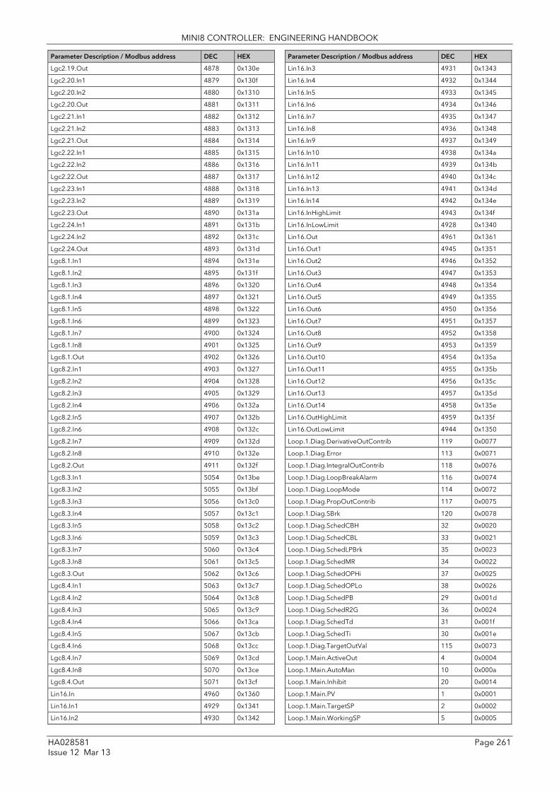
MINI8 CONTROLLER: ENGINEERING HANDBOOK
HA028581 Page 261 Issue 12 Mar 13
Parameter Description / Modbus address DEC HEX
Lgc2.19.Out 4878 0x130e
Lgc2.20.In1 4879 0x130f
Lgc2.20.In2 4880 0x1310
Lgc2.20.Out 4881 0x1311
Lgc2.21.In1 4882 0x1312
Lgc2.21.In2 4883 0x1313
Lgc2.21.Out 4884 0x1314
Lgc2.22.In1 4885 0x1315
Lgc2.22.In2 4886 0x1316
Lgc2.22.Out 4887 0x1317
Lgc2.23.In1 4888 0x1318
Lgc2.23.In2 4889 0x1319
Lgc2.23.Out 4890 0x131a
Lgc2.24.In1 4891 0x131b
Lgc2.24.In2 4892 0x131c
Lgc2.24.Out 4893 0x131d
Lgc8.1.In1 4894 0x131e
Lgc8.1.In2 4895 0x131f
Lgc8.1.In3 4896 0x1320
Lgc8.1.In4 4897 0x1321
Lgc8.1.In5 4898 0x1322
Lgc8.1.In6 4899 0x1323
Lgc8.1.In7 4900 0x1324
Lgc8.1.In8 4901 0x1325
Lgc8.1.Out 4902 0x1326
Lgc8.2.In1 4903 0x1327
Lgc8.2.In2 4904 0x1328
Lgc8.2.In3 4905 0x1329
Lgc8.2.In4 4906 0x132a
Lgc8.2.In5 4907 0x132b
Lgc8.2.In6 4908 0x132c
Lgc8.2.In7 4909 0x132d
Lgc8.2.In8 4910 0x132e
Lgc8.2.Out 4911 0x132f
Lgc8.3.In1 5054 0x13be
Lgc8.3.In2 5055 0x13bf
Lgc8.3.In3 5056 0x13c0
Lgc8.3.In4 5057 0x13c1
Lgc8.3.In5 5058 0x13c2
Lgc8.3.In6 5059 0x13c3
Lgc8.3.In7 5060 0x13c4
Lgc8.3.In8 5061 0x13c5
Lgc8.3.Out 5062 0x13c6
Lgc8.4.In1 5063 0x13c7
Lgc8.4.In2 5064 0x13c8
Lgc8.4.In3 5065 0x13c9
Lgc8.4.In4 5066 0x13ca
Lgc8.4.In5 5067 0x13cb
Lgc8.4.In6 5068 0x13cc
Lgc8.4.In7 5069 0x13cd
Lgc8.4.In8 5070 0x13ce
Lgc8.4.Out 5071 0x13cf
Lin16.In 4960 0x1360
Lin16.In1 4929 0x1341
Lin16.In2 4930 0x1342
Parameter Description / Modbus address DEC HEX
Lin16.In3 4931 0x1343
Lin16.In4 4932 0x1344
Lin16.In5 4933 0x1345
Lin16.In6 4934 0x1346
Lin16.In7 4935 0x1347
Lin16.In8 4936 0x1348
Lin16.In9 4937 0x1349
Lin16.In10 4938 0x134a
Lin16.In11 4939 0x134b
Lin16.In12 4940 0x134c
Lin16.In13 4941 0x134d
Lin16.In14 4942 0x134e
Lin16.InHighLimit 4943 0x134f
Lin16.InLowLimit 4928 0x1340
Lin16.Out 4961 0x1361
Lin16.Out1 4945 0x1351
Lin16.Out2 4946 0x1352
Lin16.Out3 4947 0x1353
Lin16.Out4 4948 0x1354
Lin16.Out5 4949 0x1355
Lin16.Out6 4950 0x1356
Lin16.Out7 4951 0x1357
Lin16.Out8 4952 0x1358
Lin16.Out9 4953 0x1359
Lin16.Out10 4954 0x135a
Lin16.Out11 4955 0x135b
Lin16.Out12 4956 0x135c
Lin16.Out13 4957 0x135d
Lin16.Out14 4958 0x135e
Lin16.OutHighLimit 4959 0x135f
Lin16.OutLowLimit 4944 0x1350
Loop.1.Diag.DerivativeOutContrib 119 0x0077
Loop.1.Diag.Error 113 0x0071
Loop.1.Diag.IntegralOutContrib 118 0x0076
Loop.1.Diag.LoopBreakAlarm 116 0x0074
Loop.1.Diag.LoopMode 114 0x0072
Loop.1.Diag.PropOutContrib 117 0x0075
Loop.1.Diag.SBrk 120 0x0078
Loop.1.Diag.SchedCBH 32 0x0020
Loop.1.Diag.SchedCBL 33 0x0021
Loop.1.Diag.SchedLPBrk 35 0x0023
Loop.1.Diag.SchedMR 34 0x0022
Loop.1.Diag.SchedOPHi 37 0x0025
Loop.1.Diag.SchedOPLo 38 0x0026
Loop.1.Diag.SchedPB 29 0x001d
Loop.1.Diag.SchedR2G 36 0x0024
Loop.1.Diag.SchedTd 31 0x001f
Loop.1.Diag.SchedTi 30 0x001e
Loop.1.Diag.TargetOutVal 115 0x0073
Loop.1.Main.ActiveOut 4 0x0004
Loop.1.Main.AutoMan 10 0x000a
Loop.1.Main.Inhibit 20 0x0014
Loop.1.Main.PV 1 0x0001
Loop.1.Main.TargetSP 2 0x0002
Loop.1.Main.WorkingSP 5 0x0005

MINI8 CONTROLLER: ENGINEERING HANDBOOK
Page 262 HA028581 Issue 12 Mar 13
Parameter Description / Modbus address DEC HEX
Loop.1.OP.Ch1OnOffHysteresis 84 0x0054
Loop.1.OP.Ch1Out 82 0x0052
Loop.1.OP.Ch2Deadband 16 0x0010
Loop.1.OP.Ch2OnOffHysteresis 85 0x0055
Loop.1.OP.Ch2Out 83 0x0053
Loop.1.OP.CoolType 93 0x005d
Loop.1.OP.EnablePowerFeedforward 91 0x005b
Loop.1.OP.FeedForwardGain 95 0x005f
Loop.1.OP.FeedForwardOffset 96 0x0060
Loop.1.OP.FeedForwardTrimLimit 97 0x0061
Loop.1.OP.FeedForwardType 94 0x005e
Loop.1.OP.FeedForwardVal 98 0x0062
Loop.1.OP.FF_Rem 103 0x0067
Loop.1.OP.ManualMode 90 0x005a
Loop.1.OP.ManualOutVal 3 0x0003
Loop.1.OP.MeasuredPower 92 0x005c
Loop.1.OP.OutputHighLimit 80 0x0050
Loop.1.OP.OutputLowLimit 81 0x0051
Loop.1.OP.Rate 86 0x0056
Loop.1.OP.RateDisable 87 0x0057
Loop.1.OP.RemOPH 102 0x0066
Loop.1.OP.RemOPL 101 0x0065
Loop.1.OP.SafeOutVal 89 0x0059
Loop.1.OP.SBrkOP 123 0x007B
Loop.1.OP.SensorBreakMode 88 0x0058
Loop.1.OP.TrackEnable 100 0x0064
Loop.1.OP.TrackOutVal 99 0x0063
Loop.1.PID.ActiveSet 28 0x001c
Loop.1.PID.Boundary1-2 26 0x001a
Loop.1.PID.Boundary2-3 27 0x001b
Loop.1.PID.CutbackHigh 18 0x0012
Loop.1.PID.CutbackHigh2 46 0x002e
Loop.1.PID.CutbackHigh3 56 0x0038
Loop.1.PID.CutbackLow 17 0x0011
Loop.1.PID.CutbackLow2 47 0x002f
Loop.1.PID.CutbackLow3 57 0x0039
Loop.1.PID.DerivativeTime 9 0x0009
Loop.1.PID.DerivativeTime2 45 0x002d
Loop.1.PID.DerivativeTime3 55 0x0037
Loop.1.PID.IntegralTime 8 0x0008
Loop.1.PID.IntegralTime2 44 0x002c
Loop.1.PID.IntegralTime3 54 0x0036
Loop.1.PID.LoopBreakTime 40 0x0028
Loop.1.PID.LoopBreakTime2 49 0x0031
Loop.1.PID.LoopBreakTime3 59 0x003b
Loop.1.PID.ManualReset 39 0x0027
Loop.1.PID.ManualReset2 48 0x0030
Loop.1.PID.ManualReset3 58 0x003a
Loop.1.PID.NumSets 64 0x0040
Loop.1.PID.OutputHi 41 0x0029
Loop.1.PID.OutputHi2 51 0x0033
Loop.1.PID.OutputHi3 61 0x003d
Loop.1.PID.OutputLo 42 0x002a
Loop.1.PID.OutputLo2 52 0x0034
Loop.1.PID.OutputLo3 62 0x003e
Loop.1.PID.ProportionalBand 6 0x0006
Parameter Description / Modbus address DEC HEX
Loop.1.PID.ProportionalBand2 43 0x002b
Loop.1.PID.ProportionalBand3 53 0x0035
Loop.1.PID.RelCh2Gain 19 0x0013
Loop.1.PID.RelCh2Gain2 50 0x0032
Loop.1.PID.RelCh2Gain3 60 0x003c
Loop.1.PID.SchedulerRemoteInput 65 0x0041
Loop.1.PID.SchedulerType 63 0x003f
Loop.1.Setup.CH1ControlType 22 0x0016
Loop.1.Setup.CH2ControlType 23 0x0017
Loop.1.Setup.ControlAction 7 0x0007
Loop.1.Setup.DerivativeType 25 0x0019
Loop.1.Setup.LoopType 21 0x0015
Loop.1.Setup.PBUnits 24 0x0018
Loop.1.SP.AltSP 68 0x0044
Loop.1.SP.AltSPSelect 69 0x0045
Loop.1.SP.ManualTrack 75 0x004b
Loop.1.SP.RangeHigh 12 0x000c
Loop.1.SP.RangeLow 11 0x000b
Loop.1.SP.Rate 70 0x0046
Loop.1.SP.RateDisable 71 0x0047
Loop.1.SP.RateDone 79 0x004f
Loop.1.SP.SP1 13 0x000d
Loop.1.SP.SP2 14 0x000e
Loop.1.SP.SPHighLimit 66 0x0042
Loop.1.SP.SPLowLimit 67 0x0043
Loop.1.SP.SPSelect 15 0x000f
Loop.1.SP.SPTrack 76 0x004c
Loop.1.SP.SPTrim 72 0x0048
Loop.1.SP.SPTrimHighLimit 73 0x0049
Loop.1.SP.SPTrimLowLimit 74 0x004a
Loop.1.SP.TrackPV 77 0x004d
Loop.1.SP.TrackSP 78 0x004e
Loop.1.Tune.AutotuneEnable 108 0x006c
Loop.1.Tune.OutputHighLimit 105 0x0069
Loop.1.Tune.OutputLowLimit 106 0x006a
Loop.1.Tune.Stage 111 0x006f
Loop.1.Tune.StageTime 112 0x0070
Loop.1.Tune.State 110 0x006e
Loop.1.Tune.StepSize 109 0x006d
Loop.1.Tune.Type 104 0x0068
Loop.2.Diag.DerivativeOutContrib 375 0x0177
Loop.2.Diag.Error 369 0x0171
Loop.2.Diag.IntegralOutContrib 374 0x0176
Loop.2.Diag.LoopBreakAlarm 372 0x0174
Loop.2.Diag.LoopMode 370 0x0172
Loop.2.Diag.PropOutContrib 373 0x0175
Loop.2.Diag.SBrk 376 0x0178
Loop.2.Diag.SchedCBH 288 0x0120
Loop.2.Diag.SchedCBL 289 0x0121
Loop.2.Diag.SchedLPBrk 291 0x0123
Loop.2.Diag.SchedMR 290 0x0122
Loop.2.Diag.SchedOPHi 293 0x0125
Loop.2.Diag.SchedOPLo 294 0x0126
Loop.2.Diag.SchedPB 285 0x011d
Loop.2.Diag.SchedR2G 292 0x0124
Loop.2.Diag.SchedTd 287 0x011f

MINI8 CONTROLLER: ENGINEERING HANDBOOK
HA028581 Page 263 Issue 12 Mar 13
Parameter Description / Modbus address DEC HEX
Loop.2.Diag.SchedTi 286 0x011e
Loop.2.Diag.TargetOutVal 371 0x0173
Loop.2.Main.ActiveOut 260 0x0104
Loop.2.Main.AutoMan 266 0x010a
Loop.2.Main.Inhibit 276 0x0114
Loop.2.Main.PV 257 0x0101
Loop.2.Main.TargetSP 258 0x0102
Loop.2.Main.WorkingSP 261 0x0105
Loop.2.OP.Ch1OnOffHysteresis 340 0x0154
Loop.2.OP.Ch1Out 338 0x0152
Loop.2.OP.Ch2Deadband 272 0x0110
Loop.2.OP.Ch2OnOffHysteresis 341 0x0155
Loop.2.OP.Ch2Out 339 0x0153
Loop.2.OP.CoolType 349 0x015d
Loop.2.OP.EnablePowerFeedforward 347 0x015b
Loop.2.OP.FeedForwardGain 351 0x015f
Loop.2.OP.FeedForwardOffset 352 0x0160
Loop.2.OP.FeedForwardTrimLimit 353 0x0161
Loop.2.OP.FeedForwardType 350 0x015e
Loop.2.OP.FeedForwardVal 354 0x0162
Loop.2.OP.FF_Rem 359 0x0167
Loop.2.OP.ManualMode 346 0x015a
Loop.2.OP.ManualOutVal 259 0x0103
Loop.2.OP.MeasuredPower 348 0x015c
Loop.2.OP.OutputHighLimit 336 0x0150
Loop.2.OP.OutputLowLimit 337 0x0151
Loop.2.OP.Rate 342 0x0156
Loop.2.OP.RateDisable 343 0x0157
Loop.2.OP.RemOPH 358 0x0166
Loop.2.OP.RemOPL 357 0x0165
Loop.2.OP.SafeOutVal 345 0x0159
Loop.2.OP.SBrkOP 379 0x017B
Loop.2.OP.SensorBreakMode 344 0x0158
Loop.2.OP.TrackEnable 356 0x0164
Loop.2.OP.TrackOutVal 355 0x0163
Loop.2.PID.ActiveSet 284 0x011c
Loop.2.PID.Boundary1-2 282 0x011a
Loop.2.PID.Boundary2-3 283 0x011b
Loop.2.PID.CutbackHigh 274 0x0112
Loop.2.PID.CutbackHigh2 302 0x012e
Loop.2.PID.CutbackHigh3 312 0x0138
Loop.2.PID.CutbackLow 273 0x0111
Loop.2.PID.CutbackLow2 303 0x012f
Loop.2.PID.CutbackLow3 313 0x0139
Loop.2.PID.DerivativeTime 265 0x0109
Loop.2.PID.DerivativeTime2 301 0x012d
Loop.2.PID.DerivativeTime3 311 0x0137
Loop.2.PID.IntegralTime 264 0x0108
Loop.2.PID.IntegralTime2 300 0x012c
Loop.2.PID.IntegralTime3 310 0x0136
Loop.2.PID.LoopBreakTime 296 0x0128
Loop.2.PID.LoopBreakTime2 305 0x0131
Loop.2.PID.LoopBreakTime3 315 0x013b
Loop.2.PID.ManualReset 295 0x0127
Loop.2.PID.ManualReset2 304 0x0130
Parameter Description / Modbus address DEC HEX
Loop.2.PID.ManualReset3 314 0x013a
Loop.2.PID.NumSets 320 0x0140
Loop.2.PID.OutputHi 297 0x0129
Loop.2.PID.OutputHi2 307 0x0133
Loop.2.PID.OutputHi3 317 0x013d
Loop.2.PID.OutputLo 298 0x012a
Loop.2.PID.OutputLo2 308 0x0134
Loop.2.PID.OutputLo3 318 0x013e
Loop.2.PID.ProportionalBand 262 0x0106
Loop.2.PID.ProportionalBand2 299 0x012b
Loop.2.PID.ProportionalBand3 309 0x0135
Loop.2.PID.RelCh2Gain 275 0x0113
Loop.2.PID.RelCh2Gain2 306 0x0132
Loop.2.PID.RelCh2Gain3 316 0x013c
Loop.2.PID.SchedulerRemoteInput 321 0x0141
Loop.2.PID.SchedulerType 319 0x013f
Loop.2.Setup.CH1ControlType 278 0x0116
Loop.2.Setup.CH2ControlType 279 0x0117
Loop.2.Setup.ControlAction 263 0x0107
Loop.2.Setup.DerivativeType 281 0x0119
Loop.2.Setup.LoopType 277 0x0115
Loop.2.Setup.PBUnits 280 0x0118
Loop.2.SP.AltSP 324 0x0144
Loop.2.SP.AltSPSelect 325 0x0145
Loop.2.SP.ManualTrack 331 0x014b
Loop.2.SP.RangeHigh 268 0x010c
Loop.2.SP.RangeLow 267 0x010b
Loop.2.SP.Rate 326 0x0146
Loop.2.SP.RateDisable 327 0x0147
Loop.2.SP.RateDone 335 0x014f
Loop.2.SP.SP1 269 0x010d
Loop.2.SP.SP2 270 0x010e
Loop.2.SP.SPHighLimit 322 0x0142
Loop.2.SP.SPLowLimit 323 0x0143
Loop.2.SP.SPSelect 271 0x010f
Loop.2.SP.SPTrack 332 0x014c
Loop.2.SP.SPTrim 328 0x0148
Loop.2.SP.SPTrimHighLimit 329 0x0149
Loop.2.SP.SPTrimLowLimit 330 0x014a
Loop.2.SP.TrackPV 333 0x014d
Loop.2.SP.TrackSP 334 0x014e
Loop.2.Tune.AutotuneEnable 364 0x016c
Loop.2.Tune.OutputHighLimit 361 0x0169
Loop.2.Tune.OutputLowLimit 362 0x016a
Loop.2.Tune.Stage 367 0x016f
Loop.2.Tune.StageTime 368 0x0170
Loop.2.Tune.State 366 0x016e
Loop.2.Tune.StepSize 365 0x016d
Loop.2.Tune.Type 360 0x0168
Loop.3.Diag.DerivativeOutContrib 631 0x0277
Loop.3.Diag.Error 625 0x0271
Loop.3.Diag.IntegralOutContrib 630 0x0276
Loop.3.Diag.LoopBreakAlarm 628 0x0274
Loop.3.Diag.LoopMode 626 0x0272
Loop.3.Diag.PropOutContrib 629 0x0275

MINI8 CONTROLLER: ENGINEERING HANDBOOK
Page 264 HA028581 Issue 12 Mar 13
Parameter Description / Modbus address DEC HEX
Loop.3.Diag.SBrk 632 0x0278
Loop.3.Diag.SchedCBH 544 0x0220
Loop.3.Diag.SchedCBL 545 0x0221
Loop.3.Diag.SchedLPBrk 547 0x0223
Loop.3.Diag.SchedMR 546 0x0222
Loop.3.Diag.SchedOPHi 549 0x0225
Loop.3.Diag.SchedOPLo 550 0x0226
Loop.3.Diag.SchedPB 541 0x021d
Loop.3.Diag.SchedR2G 548 0x0224
Loop.3.Diag.SchedTd 543 0x021f
Loop.3.Diag.SchedTi 542 0x021e
Loop.3.Diag.TargetOutVal 627 0x0273
Loop.3.Main.ActiveOut 516 0x0204
Loop.3.Main.AutoMan 522 0x020a
Loop.3.Main.Inhibit 532 0x0214
Loop.3.Main.PV 513 0x0201
Loop.3.Main.TargetSP 514 0x0202
Loop.3.Main.WorkingSP 517 0x0205
Loop.3.OP.Ch1OnOffHysteresis 596 0x0254
Loop.3.OP.Ch1Out 594 0x0252
Loop.3.OP.Ch2Deadband 528 0x0210
Loop.3.OP.Ch2OnOffHysteresis 597 0x0255
Loop.3.OP.Ch2Out 595 0x0253
Loop.3.OP.CoolType 605 0x025d
Loop.3.OP.EnablePowerFeedforward 603 0x025b
Loop.3.OP.FeedForwardGain 607 0x025f
Loop.3.OP.FeedForwardOffset 608 0x0260
Loop.3.OP.FeedForwardTrimLimit 609 0x0261
Loop.3.OP.FeedForwardType 606 0x025e
Loop.3.OP.FeedForwardVal 610 0x0262
Loop.3.OP.FF_Rem 615 0x0267
Loop.3.OP.ManualMode 602 0x025a
Loop.3.OP.ManualOutVal 515 0x0203
Loop.3.OP.MeasuredPower 604 0x025c
Loop.3.OP.OutputHighLimit 592 0x0250
Loop.3.OP.OutputLowLimit 593 0x0251
Loop.3.OP.Rate 598 0x0256
Loop.3.OP.RateDisable 599 0x0257
Loop.3.OP.RemOPH 614 0x0266
Loop.3.OP.RemOPL 613 0x0265
Loop.3.OP.SafeOutVal 601 0x0259
Loop.3.OP.SBrkOP 635 0x027B
Loop.3.OP.SensorBreakMode 600 0x0258
Loop.3.OP.TrackEnable 612 0x0264
Loop.3.OP.TrackOutVal 611 0x0263
Loop.3.PID.ActiveSet 540 0x021c
Loop.3.PID.Boundary1-2 538 0x021a
Loop.3.PID.Boundary2-3 539 0x021b
Loop.3.PID.CutbackHigh 530 0x0212
Loop.3.PID.CutbackHigh2 558 0x022e
Loop.3.PID.CutbackHigh3 568 0x0238
Loop.3.PID.CutbackLow 529 0x0211
Loop.3.PID.CutbackLow2 559 0x022f
Loop.3.PID.CutbackLow3 569 0x0239
Loop.3.PID.DerivativeTime 521 0x0209
Loop.3.PID.DerivativeTime2 557 0x022d
Parameter Description / Modbus address DEC HEX
Loop.3.PID.DerivativeTime3 567 0x0237
Loop.3.PID.IntegralTime 520 0x0208
Loop.3.PID.IntegralTime2 556 0x022c
Loop.3.PID.IntegralTime3 566 0x0236
Loop.3.PID.LoopBreakTime 552 0x0228
Loop.3.PID.LoopBreakTime2 561 0x0231
Loop.3.PID.LoopBreakTime3 571 0x023b
Loop.3.PID.ManualReset 551 0x0227
Loop.3.PID.ManualReset2 560 0x0230
Loop.3.PID.ManualReset3 570 0x023a
Loop.3.PID.NumSets 576 0x0240
Loop.3.PID.OutputHi 553 0x0229
Loop.3.PID.OutputHi2 563 0x0233
Loop.3.PID.OutputHi3 573 0x023d
Loop.3.PID.OutputLo 554 0x022a
Loop.3.PID.OutputLo2 564 0x0234
Loop.3.PID.OutputLo3 574 0x023e
Loop.3.PID.ProportionalBand 518 0x0206
Loop.3.PID.ProportionalBand2 555 0x022b
Loop.3.PID.ProportionalBand3 565 0x0235
Loop.3.PID.RelCh2Gain 531 0x0213
Loop.3.PID.RelCh2Gain2 562 0x0232
Loop.3.PID.RelCh2Gain3 572 0x023c
Loop.3.PID.SchedulerRemoteInput 577 0x0241
Loop.3.PID.SchedulerType 575 0x023f
Loop.3.Setup.CH1ControlType 534 0x0216
Loop.3.Setup.CH2ControlType 535 0x0217
Loop.3.Setup.ControlAction 519 0x0207
Loop.3.Setup.DerivativeType 537 0x0219
Loop.3.Setup.LoopType 533 0x0215
Loop.3.Setup.PBUnits 536 0x0218
Loop.3.SP.AltSP 580 0x0244
Loop.3.SP.AltSPSelect 581 0x0245
Loop.3.SP.ManualTrack 587 0x024b
Loop.3.SP.RangeHigh 524 0x020c
Loop.3.SP.RangeLow 523 0x020b
Loop.3.SP.Rate 582 0x0246
Loop.3.SP.RateDisable 583 0x0247
Loop.3.SP.RateDone 591 0x024f
Loop.3.SP.SP1 525 0x020d
Loop.3.SP.SP2 526 0x020e
Loop.3.SP.SPHighLimit 578 0x0242
Loop.3.SP.SPLowLimit 579 0x0243
Loop.3.SP.SPSelect 527 0x020f
Loop.3.SP.SPTrack 588 0x024c
Loop.3.SP.SPTrim 584 0x0248
Loop.3.SP.SPTrimHighLimit 585 0x0249
Loop.3.SP.SPTrimLowLimit 586 0x024a
Loop.3.SP.TrackPV 589 0x024d
Loop.3.SP.TrackSP 590 0x024e
Loop.3.Tune.AutotuneEnable 620 0x026c
Loop.3.Tune.OutputHighLimit 617 0x0269
Loop.3.Tune.OutputLowLimit 618 0x026a
Loop.3.Tune.Stage 623 0x026f
Loop.3.Tune.StageTime 624 0x0270
Loop.3.Tune.State 622 0x026e

MINI8 CONTROLLER: ENGINEERING HANDBOOK
HA028581 Page 265 Issue 12 Mar 13
Parameter Description / Modbus address DEC HEX
Loop.3.Tune.StepSize 621 0x026d
Loop.3.Tune.Type 616 0x0268
Loop.4.Diag.DerivativeOutContrib 887 0x0377
Loop.4.Diag.Error 881 0x0371
Loop.4.Diag.IntegralOutContrib 886 0x0376
Loop.4.Diag.LoopBreakAlarm 884 0x0374
Loop.4.Diag.LoopMode 882 0x0372
Loop.4.Diag.PropOutContrib 885 0x0375
Loop.4.Diag.SBrk 888 0x0378
Loop.4.Diag.SchedCBH 800 0x0320
Loop.4.Diag.SchedCBL 801 0x0321
Loop.4.Diag.SchedLPBrk 803 0x0323
Loop.4.Diag.SchedMR 802 0x0322
Loop.4.Diag.SchedOPHi 805 0x0325
Loop.4.Diag.SchedOPLo 806 0x0326
Loop.4.Diag.SchedPB 797 0x031d
Loop.4.Diag.SchedR2G 804 0x0324
Loop.4.Diag.SchedTd 799 0x031f
Loop.4.Diag.SchedTi 798 0x031e
Loop.4.Diag.TargetOutVal 883 0x0373
Loop.4.Main.ActiveOut 772 0x0304
Loop.4.Main.AutoMan 778 0x030a
Loop.4.Main.Inhibit 788 0x0314
Loop.4.Main.PV 769 0x0301
Loop.4.Main.TargetSP 770 0x0302
Loop.4.Main.WorkingSP 773 0x0305
Loop.4.OP.Ch1OnOffHysteresis 852 0x0354
Loop.4.OP.Ch1Out 850 0x0352
Loop.4.OP.Ch2Deadband 784 0x0310
Loop.4.OP.Ch2OnOffHysteresis 853 0x0355
Loop.4.OP.Ch2Out 851 0x0353
Loop.4.OP.CoolType 861 0x035d
Loop.4.OP.EnablePowerFeedforward 859 0x035b
Loop.4.OP.FeedForwardGain 863 0x035f
Loop.4.OP.FeedForwardOffset 864 0x0360
Loop.4.OP.FeedForwardTrimLimit 865 0x0361
Loop.4.OP.FeedForwardType 862 0x035e
Loop.4.OP.FeedForwardVal 866 0x0362
Loop.4.OP.FF_Rem 871 0x0367
Loop.4.OP.ManualMode 858 0x035a
Loop.4.OP.ManualOutVal 771 0x0303
Loop.4.OP.MeasuredPower 860 0x035c
Loop.4.OP.OutputHighLimit 848 0x0350
Loop.4.OP.OutputLowLimit 849 0x0351
Loop.4.OP.Rate 854 0x0356
Loop.4.OP.RateDisable 855 0x0357
Loop.4.OP.RemOPH 870 0x0366
Loop.4.OP.RemOPL 869 0x0365
Loop.4.OP.SafeOutVal 857 0x0359
Loop.4.OP.SBrkOP 891 0x037B
Loop.4.OP.SensorBreakMode 856 0x0358
Loop.4.OP.TrackEnable 868 0x0364
Loop.4.OP.TrackOutVal 867 0x0363
Loop.4.PID.ActiveSet 796 0x031c
Loop.4.PID.Boundary1-2 794 0x031a
Parameter Description / Modbus address DEC HEX
Loop.4.PID.Boundary2-3 795 0x031b
Loop.4.PID.CutbackHigh 786 0x0312
Loop.4.PID.CutbackHigh2 814 0x032e
Loop.4.PID.CutbackHigh3 824 0x0338
Loop.4.PID.CutbackLow 785 0x0311
Loop.4.PID.CutbackLow2 815 0x032f
Loop.4.PID.CutbackLow3 825 0x0339
Loop.4.PID.DerivativeTime 777 0x0309
Loop.4.PID.DerivativeTime2 813 0x032d
Loop.4.PID.DerivativeTime3 823 0x0337
Loop.4.PID.IntegralTime 776 0x0308
Loop.4.PID.IntegralTime2 812 0x032c
Loop.4.PID.IntegralTime3 822 0x0336
Loop.4.PID.LoopBreakTime 808 0x0328
Loop.4.PID.LoopBreakTime2 817 0x0331
Loop.4.PID.LoopBreakTime3 827 0x033b
Loop.4.PID.ManualReset 807 0x0327
Loop.4.PID.ManualReset2 816 0x0330
Loop.4.PID.ManualReset3 826 0x033a
Loop.4.PID.NumSets 832 0x0340
Loop.4.PID.OutputHi 809 0x0329
Loop.4.PID.OutputHi2 819 0x0333
Loop.4.PID.OutputHi3 829 0x033d
Loop.4.PID.OutputLo 810 0x032a
Loop.4.PID.OutputLo2 820 0x0334
Loop.4.PID.OutputLo3 830 0x033e
Loop.4.PID.ProportionalBand 774 0x0306
Loop.4.PID.ProportionalBand2 811 0x032b
Loop.4.PID.ProportionalBand3 821 0x0335
Loop.4.PID.RelCh2Gain 787 0x0313
Loop.4.PID.RelCh2Gain2 818 0x0332
Loop.4.PID.RelCh2Gain3 828 0x033c
Loop.4.PID.SchedulerRemoteInput 833 0x0341
Loop.4.PID.SchedulerType 831 0x033f
Loop.4.Setup.CH1ControlType 790 0x0316
Loop.4.Setup.CH2ControlType 791 0x0317
Loop.4.Setup.ControlAction 775 0x0307
Loop.4.Setup.DerivativeType 793 0x0319
Loop.4.Setup.LoopType 789 0x0315
Loop.4.Setup.PBUnits 792 0x0318
Loop.4.SP.AltSP 836 0x0344
Loop.4.SP.AltSPSelect 837 0x0345
Loop.4.SP.ManualTrack 843 0x034b
Loop.4.SP.RangeHigh 780 0x030c
Loop.4.SP.RangeLow 779 0x030b
Loop.4.SP.Rate 838 0x0346
Loop.4.SP.RateDisable 839 0x0347
Loop.4.SP.RateDone 847 0x034f
Loop.4.SP.SP1 781 0x030d
Loop.4.SP.SP2 782 0x030e
Loop.4.SP.SPHighLimit 834 0x0342
Loop.4.SP.SPLowLimit 835 0x0343
Loop.4.SP.SPSelect 783 0x030f
Loop.4.SP.SPTrack 844 0x034c
Loop.4.SP.SPTrim 840 0x0348

MINI8 CONTROLLER: ENGINEERING HANDBOOK
Page 266 HA028581 Issue 12 Mar 13
Parameter Description / Modbus address DEC HEX
Loop.4.SP.SPTrimHighLimit 841 0x0349
Loop.4.SP.SPTrimLowLimit 842 0x034a
Loop.4.SP.TrackPV 845 0x034d
Loop.4.SP.TrackSP 846 0x034e
Loop.4.Tune.AutotuneEnable 876 0x036c
Loop.4.Tune.OutputHighLimit 873 0x0369
Loop.4.Tune.OutputLowLimit 874 0x036a
Loop.4.Tune.Stage 879 0x036f
Loop.4.Tune.StageTime 880 0x0370
Loop.4.Tune.State 878 0x036e
Loop.4.Tune.StepSize 877 0x036d
Loop.4.Tune.Type 872 0x0368
Loop.5.Diag.DerivativeOutContrib 1143 0x0477
Loop.5.Diag.Error 1137 0x0471
Loop.5.Diag.IntegralOutContrib 1142 0x0476
Loop.5.Diag.LoopBreakAlarm 1140 0x0474
Loop.5.Diag.LoopMode 1138 0x0472
Loop.5.Diag.PropOutContrib 1141 0x0475
Loop.5.Diag.SBrk 1144 0x0478
Loop.5.Diag.SchedCBH 1056 0x0420
Loop.5.Diag.SchedCBL 1057 0x0421
Loop.5.Diag.SchedLPBrk 1059 0x0423
Loop.5.Diag.SchedMR 1058 0x0422
Loop.5.Diag.SchedOPHi 1061 0x0425
Loop.5.Diag.SchedOPLo 1062 0x0426
Loop.5.Diag.SchedPB 1053 0x041d
Loop.5.Diag.SchedR2G 1060 0x0424
Loop.5.Diag.SchedTd 1055 0x041f
Loop.5.Diag.SchedTi 1054 0x041e
Loop.5.Diag.TargetOutVal 1139 0x0473
Loop.5.Main.ActiveOut 1028 0x0404
Loop.5.Main.AutoMan 1034 0x040a
Loop.5.Main.Inhibit 1044 0x0414
Loop.5.Main.PV 1025 0x0401
Loop.5.Main.TargetSP 1026 0x0402
Loop.5.Main.WorkingSP 1029 0x0405
Loop.5.OP.Ch1OnOffHysteresis 1108 0x0454
Loop.5.OP.Ch1Out 1106 0x0452
Loop.5.OP.Ch2Deadband 1040 0x0410
Loop.5.OP.Ch2OnOffHysteresis 1109 0x0455
Loop.5.OP.Ch2Out 1107 0x0453
Loop.5.OP.CoolType 1117 0x045d
Loop.5.OP.EnablePowerFeedforward 1115 0x045b
Loop.5.OP.FeedForwardGain 1119 0x045f
Loop.5.OP.FeedForwardOffset 1120 0x0460
Loop.5.OP.FeedForwardTrimLimit 1121 0x0461
Loop.5.OP.FeedForwardType 1118 0x045e
Loop.5.OP.FeedForwardVal 1122 0x0462
Loop.5.OP.FF_Rem 1127 0x0467
Loop.5.OP.ManualMode 1114 0x045a
Loop.5.OP.ManualOutVal 1027 0x0403
Loop.5.OP.MeasuredPower 1116 0x045c
Loop.5.OP.OutputHighLimit 1104 0x0450
Loop.5.OP.OutputLowLimit 1105 0x0451
Loop.5.OP.Rate 1110 0x0456
Loop.5.OP.RateDisable 1111 0x0457
Parameter Description / Modbus address DEC HEX
Loop.5.OP.RemOPH 1126 0x0466
Loop.5.OP.RemOPL 1125 0x0465
Loop.5.OP.SafeOutVal 1113 0x0459
Loop.5.OP.SBrkOP 1147 0x047B
Loop.5.OP.SensorBreakMode 1112 0x0458
Loop.5.OP.TrackEnable 1124 0x0464
Loop.5.OP.TrackOutVal 1123 0x0463
Loop.5.PID.ActiveSet 1052 0x041c
Loop.5.PID.Boundary1-2 1050 0x041a
Loop.5.PID.Boundary2-3 1051 0x041b
Loop.5.PID.CutbackHigh 1042 0x0412
Loop.5.PID.CutbackHigh2 1070 0x042e
Loop.5.PID.CutbackHigh3 1080 0x0438
Loop.5.PID.CutbackLow 1041 0x0411
Loop.5.PID.CutbackLow2 1071 0x042f
Loop.5.PID.CutbackLow3 1081 0x0439
Loop.5.PID.DerivativeTime 1033 0x0409
Loop.5.PID.DerivativeTime2 1069 0x042d
Loop.5.PID.DerivativeTime3 1079 0x0437
Loop.5.PID.IntegralTime 1032 0x0408
Loop.5.PID.IntegralTime2 1068 0x042c
Loop.5.PID.IntegralTime3 1078 0x0436
Loop.5.PID.LoopBreakTime 1064 0x0428
Loop.5.PID.LoopBreakTime2 1073 0x0431
Loop.5.PID.LoopBreakTime3 1083 0x043b
Loop.5.PID.ManualReset 1063 0x0427
Loop.5.PID.ManualReset2 1072 0x0430
Loop.5.PID.ManualReset3 1082 0x043a
Loop.5.PID.NumSets 1088 0x0440
Loop.5.PID.OutputHi 1065 0x0429
Loop.5.PID.OutputHi2 1075 0x0433
Loop.5.PID.OutputHi3 1085 0x043d
Loop.5.PID.OutputLo 1066 0x042a
Loop.5.PID.OutputLo2 1076 0x0434
Loop.5.PID.OutputLo3 1086 0x043e
Loop.5.PID.ProportionalBand 1030 0x0406
Loop.5.PID.ProportionalBand2 1067 0x042b
Loop.5.PID.ProportionalBand3 1077 0x0435
Loop.5.PID.RelCh2Gain 1043 0x0413
Loop.5.PID.RelCh2Gain2 1074 0x0432
Loop.5.PID.RelCh2Gain3 1084 0x043c
Loop.5.PID.SchedulerRemoteInput 1089 0x0441
Loop.5.PID.SchedulerType 1087 0x043f
Loop.5.Setup.CH1ControlType 1046 0x0416
Loop.5.Setup.CH2ControlType 1047 0x0417
Loop.5.Setup.ControlAction 1031 0x0407
Loop.5.Setup.DerivativeType 1049 0x0419
Loop.5.Setup.LoopType 1045 0x0415
Loop.5.Setup.PBUnits 1048 0x0418
Loop.5.SP.AltSP 1092 0x0444
Loop.5.SP.AltSPSelect 1093 0x0445
Loop.5.SP.ManualTrack 1099 0x044b
Loop.5.SP.RangeHigh 1036 0x040c
Loop.5.SP.RangeLow 1035 0x040b
Loop.5.SP.Rate 1094 0x0446
Loop.5.SP.RateDisable 1095 0x0447

MINI8 CONTROLLER: ENGINEERING HANDBOOK
HA028581 Page 267 Issue 12 Mar 13
Parameter Description / Modbus address DEC HEX
Loop.5.SP.RateDone 1103 0x044f
Loop.5.SP.SP1 1037 0x040d
Loop.5.SP.SP2 1038 0x040e
Loop.5.SP.SPHighLimit 1090 0x0442
Loop.5.SP.SPLowLimit 1091 0x0443
Loop.5.SP.SPSelect 1039 0x040f
Loop.5.SP.SPTrack 1100 0x044c
Loop.5.SP.SPTrim 1096 0x0448
Loop.5.SP.SPTrimHighLimit 1097 0x0449
Loop.5.SP.SPTrimLowLimit 1098 0x044a
Loop.5.SP.TrackPV 1101 0x044d
Loop.5.SP.TrackSP 1102 0x044e
Loop.5.Tune.AutotuneEnable 1132 0x046c
Loop.5.Tune.OutputHighLimit 1129 0x0469
Loop.5.Tune.OutputLowLimit 1130 0x046a
Loop.5.Tune.Stage 1135 0x046f
Loop.5.Tune.StageTime 1136 0x0470
Loop.5.Tune.State 1134 0x046e
Loop.5.Tune.StepSize 1133 0x046d
Loop.5.Tune.Type 1128 0x0468
Loop.6.Diag.DerivativeOutContrib 1399 0x0577
Loop.6.Diag.Error 1393 0x0571
Loop.6.Diag.IntegralOutContrib 1398 0x0576
Loop.6.Diag.LoopBreakAlarm 1396 0x0574
Loop.6.Diag.LoopMode 1394 0x0572
Loop.6.Diag.PropOutContrib 1397 0x0575
Loop.6.Diag.SBrk 1400 0x0578
Loop.6.Diag.SchedCBH 1312 0x0520
Loop.6.Diag.SchedCBL 1313 0x0521
Loop.6.Diag.SchedLPBrk 1315 0x0523
Loop.6.Diag.SchedMR 1314 0x0522
Loop.6.Diag.SchedOPHi 1317 0x0525
Loop.6.Diag.SchedOPLo 1318 0x0526
Loop.6.Diag.SchedPB 1309 0x051d
Loop.6.Diag.SchedR2G 1316 0x0524
Loop.6.Diag.SchedTd 1311 0x051f
Loop.6.Diag.SchedTi 1310 0x051e
Loop.6.Diag.TargetOutVal 1395 0x0573
Loop.6.Main.ActiveOut 1284 0x0504
Loop.6.Main.AutoMan 1290 0x050a
Loop.6.Main.Inhibit 1300 0x0514
Loop.6.Main.PV 1281 0x0501
Loop.6.Main.TargetSP 1282 0x0502
Loop.6.Main.WorkingSP 1285 0x0505
Loop.6.OP.Ch1OnOffHysteresis 1364 0x0554
Loop.6.OP.Ch1Out 1362 0x0552
Loop.6.OP.Ch2Deadband 1296 0x0510
Loop.6.OP.Ch2OnOffHysteresis 1365 0x0555
Loop.6.OP.Ch2Out 1363 0x0553
Loop.6.OP.CoolType 1373 0x055d
Loop.6.OP.EnablePowerFeedforward 1371 0x055b
Loop.6.OP.FeedForwardGain 1375 0x055f
Loop.6.OP.FeedForwardOffset 1376 0x0560
Loop.6.OP.FeedForwardTrimLimit 1377 0x0561
Loop.6.OP.FeedForwardType 1374 0x055e
Parameter Description / Modbus address DEC HEX
Loop.6.OP.FeedForwardVal 1378 0x0562
Loop.6.OP.FF_Rem 1383 0x0567
Loop.6.OP.ManualMode 1370 0x055a
Loop.6.OP.ManualOutVal 1283 0x0503
Loop.6.OP.MeasuredPower 1372 0x055c
Loop.6.OP.OutputHighLimit 1360 0x0550
Loop.6.OP.OutputLowLimit 1361 0x0551
Loop.6.OP.Rate 1366 0x0556
Loop.6.OP.RateDisable 1367 0x0557
Loop.6.OP.RemOPH 1382 0x0566
Loop.6.OP.RemOPL 1381 0x0565
Loop.6.OP.SafeOutVal 1369 0x0559
Loop.6.OP.SBrkOP 1403 0x057B
Loop.6.OP.SensorBreakMode 1368 0x0558
Loop.6.OP.TrackEnable 1380 0x0564
Loop.6.OP.TrackOutVal 1379 0x0563
Loop.6.PID.ActiveSet 1308 0x051c
Loop.6.PID.Boundary1-2 1306 0x051a
Loop.6.PID.Boundary2-3 1307 0x051b
Loop.6.PID.CutbackHigh 1298 0x0512
Loop.6.PID.CutbackHigh2 1326 0x052e
Loop.6.PID.CutbackHigh3 1336 0x0538
Loop.6.PID.CutbackLow 1297 0x0511
Loop.6.PID.CutbackLow2 1327 0x052f
Loop.6.PID.CutbackLow3 1337 0x0539
Loop.6.PID.DerivativeTime 1289 0x0509
Loop.6.PID.DerivativeTime2 1325 0x052d
Loop.6.PID.DerivativeTime3 1335 0x0537
Loop.6.PID.IntegralTime 1288 0x0508
Loop.6.PID.IntegralTime2 1324 0x052c
Loop.6.PID.IntegralTime3 1334 0x0536
Loop.6.PID.LoopBreakTime 1320 0x0528
Loop.6.PID.LoopBreakTime2 1329 0x0531
Loop.6.PID.LoopBreakTime3 1339 0x053b
Loop.6.PID.ManualReset 1319 0x0527
Loop.6.PID.ManualReset2 1328 0x0530
Loop.6.PID.ManualReset3 1338 0x053a
Loop.6.PID.NumSets 1344 0x0540
Loop.6.PID.OutputHi 1321 0x0529
Loop.6.PID.OutputHi2 1331 0x0533
Loop.6.PID.OutputHi3 1341 0x053d
Loop.6.PID.OutputLo 1322 0x052a
Loop.6.PID.OutputLo2 1332 0x0534
Loop.6.PID.OutputLo3 1342 0x053e
Loop.6.PID.ProportionalBand 1286 0x0506
Loop.6.PID.ProportionalBand2 1323 0x052b
Loop.6.PID.ProportionalBand3 1333 0x0535
Loop.6.PID.RelCh2Gain 1299 0x0513
Loop.6.PID.RelCh2Gain2 1330 0x0532
Loop.6.PID.RelCh2Gain3 1340 0x053c
Loop.6.PID.SchedulerRemoteInput 1345 0x0541
Loop.6.PID.SchedulerType 1343 0x053f
Loop.6.Setup.CH1ControlType 1302 0x0516
Loop.6.Setup.CH2ControlType 1303 0x0517
Loop.6.Setup.ControlAction 1287 0x0507

MINI8 CONTROLLER: ENGINEERING HANDBOOK
Page 268 HA028581 Issue 12 Mar 13
Parameter Description / Modbus address DEC HEX
Loop.6.Setup.DerivativeType 1305 0x0519
Loop.6.Setup.LoopType 1301 0x0515
Loop.6.Setup.PBUnits 1304 0x0518
Loop.6.SP.AltSP 1348 0x0544
Loop.6.SP.AltSPSelect 1349 0x0545
Loop.6.SP.ManualTrack 1355 0x054b
Loop.6.SP.RangeHigh 1292 0x050c
Loop.6.SP.RangeLow 1291 0x050b
Loop.6.SP.Rate 1350 0x0546
Loop.6.SP.RateDisable 1351 0x0547
Loop.6.SP.RateDone 1359 0x054f
Loop.6.SP.SP1 1293 0x050d
Loop.6.SP.SP2 1294 0x050e
Loop.6.SP.SPHighLimit 1346 0x0542
Loop.6.SP.SPLowLimit 1347 0x0543
Loop.6.SP.SPSelect 1295 0x050f
Loop.6.SP.SPTrack 1356 0x054c
Loop.6.SP.SPTrim 1352 0x0548
Loop.6.SP.SPTrimHighLimit 1353 0x0549
Loop.6.SP.SPTrimLowLimit 1354 0x054a
Loop.6.SP.TrackPV 1357 0x054d
Loop.6.SP.TrackSP 1358 0x054e
Loop.6.Tune.AutotuneEnable 1388 0x056c
Loop.6.Tune.OutputHighLimit 1385 0x0569
Loop.6.Tune.OutputLowLimit 1386 0x056a
Loop.6.Tune.Stage 1391 0x056f
Loop.6.Tune.StageTime 1392 0x0570
Loop.6.Tune.State 1390 0x056e
Loop.6.Tune.StepSize 1389 0x056d
Loop.6.Tune.Type 1384 0x0568
Loop.7.Diag.DerivativeOutContrib 1655 0x0677
Loop.7.Diag.Error 1649 0x0671
Loop.7.Diag.IntegralOutContrib 1654 0x0676
Loop.7.Diag.LoopBreakAlarm 1652 0x0674
Loop.7.Diag.LoopMode 1650 0x0672
Loop.7.Diag.PropOutContrib 1653 0x0675
Loop.7.Diag.SBrk 1656 0x0678
Loop.7.Diag.SchedCBH 1568 0x0620
Loop.7.Diag.SchedCBL 1569 0x0621
Loop.7.Diag.SchedLPBrk 1571 0x0623
Loop.7.Diag.SchedMR 1570 0x0622
Loop.7.Diag.SchedOPHi 1573 0x0625
Loop.7.Diag.SchedOPLo 1574 0x0626
Loop.7.Diag.SchedPB 1565 0x061d
Loop.7.Diag.SchedR2G 1572 0x0624
Loop.7.Diag.SchedTd 1567 0x061f
Loop.7.Diag.SchedTi 1566 0x061e
Loop.7.Diag.TargetOutVal 1651 0x0673
Loop.7.Main.ActiveOut 1540 0x0604
Loop.7.Main.AutoMan 1546 0x060a
Loop.7.Main.Inhibit 1556 0x0614
Loop.7.Main.PV 1537 0x0601
Loop.7.Main.TargetSP 1538 0x0602
Loop.7.Main.WorkingSP 1541 0x0605
Loop.7.OP.Ch1OnOffHysteresis 1620 0x0654
Loop.7.OP.Ch1Out 1618 0x0652
Parameter Description / Modbus address DEC HEX
Loop.7.OP.Ch2Deadband 1552 0x0610
Loop.7.OP.Ch2OnOffHysteresis 1621 0x0655
Loop.7.OP.Ch2Out 1619 0x0653
Loop.7.OP.CoolType 1629 0x065d
Loop.7.OP.EnablePowerFeedforward 1627 0x065b
Loop.7.OP.FeedForwardGain 1631 0x065f
Loop.7.OP.FeedForwardOffset 1632 0x0660
Loop.7.OP.FeedForwardTrimLimit 1633 0x0661
Loop.7.OP.FeedForwardType 1630 0x065e
Loop.7.OP.FeedForwardVal 1634 0x0662
Loop.7.OP.FF_Rem 1639 0x0667
Loop.7.OP.ManualMode 1626 0x065a
Loop.7.OP.ManualOutVal 1539 0x0603
Loop.7.OP.MeasuredPower 1628 0x065c
Loop.7.OP.OutputHighLimit 1616 0x0650
Loop.7.OP.OutputLowLimit 1617 0x0651
Loop.7.OP.Rate 1622 0x0656
Loop.7.OP.RateDisable 1623 0x0657
Loop.7.OP.RemOPH 1638 0x0666
Loop.7.OP.RemOPL 1637 0x0665
Loop.7.OP.SafeOutVal 1625 0x0659
Loop.7.OP.SBrkOP 1659 0x067B
Loop.7.OP.SensorBreakMode 1624 0x0658
Loop.7.OP.TrackEnable 1636 0x0664
Loop.7.OP.TrackOutVal 1635 0x0663
Loop.7.PID.ActiveSet 1564 0x061c
Loop.7.PID.Boundary1-2 1562 0x061a
Loop.7.PID.Boundary2-3 1563 0x061b
Loop.7.PID.CutbackHigh 1554 0x0612
Loop.7.PID.CutbackHigh2 1582 0x062e
Loop.7.PID.CutbackHigh3 1592 0x0638
Loop.7.PID.CutbackLow 1553 0x0611
Loop.7.PID.CutbackLow2 1583 0x062f
Loop.7.PID.CutbackLow3 1593 0x0639
Loop.7.PID.DerivativeTime 1545 0x0609
Loop.7.PID.DerivativeTime2 1581 0x062d
Loop.7.PID.DerivativeTime3 1591 0x0637
Loop.7.PID.IntegralTime 1544 0x0608
Loop.7.PID.IntegralTime2 1580 0x062c
Loop.7.PID.IntegralTime3 1590 0x0636
Loop.7.PID.LoopBreakTime 1576 0x0628
Loop.7.PID.LoopBreakTime2 1585 0x0631
Loop.7.PID.LoopBreakTime3 1595 0x063b
Loop.7.PID.ManualReset 1575 0x0627
Loop.7.PID.ManualReset2 1584 0x0630
Loop.7.PID.ManualReset3 1594 0x063a
Loop.7.PID.NumSets 1600 0x0640
Loop.7.PID.OutputHi 1577 0x0629
Loop.7.PID.OutputHi2 1587 0x0633
Loop.7.PID.OutputHi3 1597 0x063d
Loop.7.PID.OutputLo 1578 0x062a
Loop.7.PID.OutputLo2 1588 0x0634
Loop.7.PID.OutputLo3 1598 0x063e
Loop.7.PID.ProportionalBand 1542 0x0606
Loop.7.PID.ProportionalBand2 1579 0x062b
Loop.7.PID.ProportionalBand3 1589 0x0635

MINI8 CONTROLLER: ENGINEERING HANDBOOK
HA028581 Page 269 Issue 12 Mar 13
Parameter Description / Modbus address DEC HEX
Loop.7.PID.RelCh2Gain 1555 0x0613
Loop.7.PID.RelCh2Gain2 1586 0x0632
Loop.7.PID.RelCh2Gain3 1596 0x063c
Loop.7.PID.SchedulerRemoteInput 1601 0x0641
Loop.7.PID.SchedulerType 1599 0x063f
Loop.7.Setup.CH1ControlType 1558 0x0616
Loop.7.Setup.CH2ControlType 1559 0x0617
Loop.7.Setup.ControlAction 1543 0x0607
Loop.7.Setup.DerivativeType 1561 0x0619
Loop.7.Setup.LoopType 1557 0x0615
Loop.7.Setup.PBUnits 1560 0x0618
Loop.7.SP.AltSP 1604 0x0644
Loop.7.SP.AltSPSelect 1605 0x0645
Loop.7.SP.ManualTrack 1611 0x064b
Loop.7.SP.RangeHigh 1548 0x060c
Loop.7.SP.RangeLow 1547 0x060b
Loop.7.SP.Rate 1606 0x0646
Loop.7.SP.RateDisable 1607 0x0647
Loop.7.SP.RateDone 1615 0x064f
Loop.7.SP.SP1 1549 0x060d
Loop.7.SP.SP2 1550 0x060e
Loop.7.SP.SPHighLimit 1602 0x0642
Loop.7.SP.SPLowLimit 1603 0x0643
Loop.7.SP.SPSelect 1551 0x060f
Loop.7.SP.SPTrack 1612 0x064c
Loop.7.SP.SPTrim 1608 0x0648
Loop.7.SP.SPTrimHighLimit 1609 0x0649
Loop.7.SP.SPTrimLowLimit 1610 0x064a
Loop.7.SP.TrackPV 1613 0x064d
Loop.7.SP.TrackSP 1614 0x064e
Loop.7.Tune.AutotuneEnable 1644 0x066c
Loop.7.Tune.OutputHighLimit 1641 0x0669
Loop.7.Tune.OutputLowLimit 1642 0x066a
Loop.7.Tune.Stage 1647 0x066f
Loop.7.Tune.StageTime 1648 0x0670
Loop.7.Tune.State 1646 0x066e
Loop.7.Tune.StepSize 1645 0x066d
Loop.7.Tune.Type 1640 0x0668
Loop.8.Diag.DerivativeOutContrib 1911 0x0777
Loop.8.Diag.Error 1905 0x0771
Loop.8.Diag.IntegralOutContrib 1910 0x0776
Loop.8.Diag.LoopBreakAlarm 1908 0x0774
Loop.8.Diag.LoopMode 1906 0x0772
Loop.8.Diag.PropOutContrib 1909 0x0775
Loop.8.Diag.SBrk 1912 0x0778
Loop.8.Diag.SchedCBH 1824 0x0720
Loop.8.Diag.SchedCBL 1825 0x0721
Loop.8.Diag.SchedLPBrk 1827 0x0723
Loop.8.Diag.SchedMR 1826 0x0722
Loop.8.Diag.SchedOPHi 1829 0x0725
Loop.8.Diag.SchedOPLo 1830 0x0726
Loop.8.Diag.SchedPB 1821 0x071d
Loop.8.Diag.SchedR2G 1828 0x0724
Loop.8.Diag.SchedTd 1823 0x071f
Loop.8.Diag.SchedTi 1822 0x071e
Parameter Description / Modbus address DEC HEX
Loop.8.Diag.TargetOutVal 1907 0x0773
Loop.8.Main.ActiveOut 1796 0x0704
Loop.8.Main.AutoMan 1802 0x070a
Loop.8.Main.Inhibit 1812 0x0714
Loop.8.Main.PV 1793 0x0701
Loop.8.Main.TargetSP 1794 0x0702
Loop.8.Main.WorkingSP 1797 0x0705
Loop.8.OP.Ch1OnOffHysteresis 1876 0x0754
Loop.8.OP.Ch1Out 1874 0x0752
Loop.8.OP.Ch2Deadband 1808 0x0710
Loop.8.OP.Ch2OnOffHysteresis 1877 0x0755
Loop.8.OP.Ch2Out 1875 0x0753
Loop.8.OP.CoolType 1885 0x075d
Loop.8.OP.EnablePowerFeedforward 1883 0x075b
Loop.8.OP.FeedForwardGain 1887 0x075f
Loop.8.OP.FeedForwardOffset 1888 0x0760
Loop.8.OP.FeedForwardTrimLimit 1889 0x0761
Loop.8.OP.FeedForwardType 1886 0x075e
Loop.8.OP.FeedForwardVal 1890 0x0762
Loop.8.OP.FF_Rem 1895 0x0767
Loop.8.OP.ManualMode 1882 0x075a
Loop.8.OP.ManualOutVal 1795 0x0703
Loop.8.OP.MeasuredPower 1884 0x075c
Loop.8.OP.OutputHighLimit 1872 0x0750
Loop.8.OP.OutputLowLimit 1873 0x0751
Loop.8.OP.Rate 1878 0x0756
Loop.8.OP.RateDisable 1879 0x0757
Loop.8.OP.RemOPH 1894 0x0766
Loop.8.OP.RemOPL 1893 0x0765
Loop.8.OP.SafeOutVal 1881 0x0759
Loop.8.OP.SBrkOP 1915 0x077B
Loop.8.OP.SensorBreakMode 1880 0x0758
Loop.8.OP.TrackEnable 1892 0x0764
Loop.8.OP.TrackOutVal 1891 0x0763
Loop.8.PID.ActiveSet 1820 0x071c
Loop.8.PID.Boundary1-2 1818 0x071a
Loop.8.PID.Boundary2-3 1819 0x071b
Loop.8.PID.CutbackHigh 1810 0x0712
Loop.8.PID.CutbackHigh2 1838 0x072e
Loop.8.PID.CutbackHigh3 1848 0x0738
Loop.8.PID.CutbackLow 1809 0x0711
Loop.8.PID.CutbackLow2 1839 0x072f
Loop.8.PID.CutbackLow3 1849 0x0739
Loop.8.PID.DerivativeTime 1801 0x0709
Loop.8.PID.DerivativeTime2 1837 0x072d
Loop.8.PID.DerivativeTime3 1847 0x0737
Loop.8.PID.IntegralTime 1800 0x0708
Loop.8.PID.IntegralTime2 1836 0x072c
Loop.8.PID.IntegralTime3 1846 0x0736
Loop.8.PID.LoopBreakTime 1832 0x0728
Loop.8.PID.LoopBreakTime2 1841 0x0731
Loop.8.PID.LoopBreakTime3 1851 0x073b
Loop.8.PID.ManualReset 1831 0x0727
Loop.8.PID.ManualReset2 1840 0x0730
Loop.8.PID.ManualReset3 1850 0x073a

MINI8 CONTROLLER: ENGINEERING HANDBOOK
Page 270 HA028581 Issue 12 Mar 13
Parameter Description / Modbus address DEC HEX
Loop.8.PID.NumSets 1856 0x0740
Loop.8.PID.OutputHi 1833 0x0729
Loop.8.PID.OutputHi2 1843 0x0733
Loop.8.PID.OutputHi3 1853 0x073d
Loop.8.PID.OutputLo 1834 0x072a
Loop.8.PID.OutputLo2 1844 0x0734
Loop.8.PID.OutputLo3 1854 0x073e
Loop.8.PID.ProportionalBand 1798 0x0706
Loop.8.PID.ProportionalBand2 1835 0x072b
Loop.8.PID.ProportionalBand3 1845 0x0735
Loop.8.PID.RelCh2Gain 1811 0x0713
Loop.8.PID.RelCh2Gain2 1842 0x0732
Loop.8.PID.RelCh2Gain3 1852 0x073c
Loop.8.PID.SchedulerRemoteInput 1857 0x0741
Loop.8.PID.SchedulerType 1855 0x073f
Loop.8.Setup.CH1ControlType 1814 0x0716
Loop.8.Setup.CH2ControlType 1815 0x0717
Loop.8.Setup.ControlAction 1799 0x0707
Loop.8.Setup.DerivativeType 1817 0x0719
Loop.8.Setup.LoopType 1813 0x0715
Loop.8.Setup.PBUnits 1816 0x0718
Loop.8.SP.AltSP 1860 0x0744
Loop.8.SP.AltSPSelect 1861 0x0745
Loop.8.SP.ManualTrack 1867 0x074b
Loop.8.SP.RangeHigh 1804 0x070c
Loop.8.SP.RangeLow 1803 0x070b
Loop.8.SP.Rate 1862 0x0746
Loop.8.SP.RateDisable 1863 0x0747
Loop.8.SP.RateDone 1871 0x074f
Loop.8.SP.SP1 1805 0x070d
Loop.8.SP.SP2 1806 0x070e
Loop.8.SP.SPHighLimit 1858 0x0742
Loop.8.SP.SPLowLimit 1859 0x0743
Loop.8.SP.SPSelect 1807 0x070f
Loop.8.SP.SPTrack 1868 0x074c
Loop.8.SP.SPTrim 1864 0x0748
Loop.8.SP.SPTrimHighLimit 1865 0x0749
Loop.8.SP.SPTrimLowLimit 1866 0x074a
Loop.8.SP.TrackPV 1869 0x074d
Loop.8.SP.TrackSP 1870 0x074e
Loop.8.Tune.AutotuneEnable 1900 0x076c
Loop.8.Tune.OutputHighLimit 1897 0x0769
Loop.8.Tune.OutputLowLimit 1898 0x076a
Loop.8.Tune.Stage 1903 0x076f
Loop.8.Tune.StageTime 1904 0x0770
Loop.8.Tune.State 1902 0x076e
Loop.8.Tune.StepSize 1901 0x076d
Loop.8.Tune.Type 1896 0x0768
Loop.9.Diag.DerivativeOutContrib 2167 0x0877
Loop.9.Diag.Error 2161 0x0871
Loop.9.Diag.IntegralOutContrib 2166 0x0876
Loop.9.Diag.LoopBreakAlarm 2164 0x0874
Loop.9.Diag.LoopMode 2162 0x0872
Loop.9.Diag.PropOutContrib 2165 0x0875
Loop.9.Diag.SBrk 2168 0x0878
Loop.9.Diag.SchedCBH 2080 0x0820
Parameter Description / Modbus address DEC HEX
Loop.9.Diag.SchedCBL 2081 0x0821
Loop.9.Diag.SchedLPBrk 2083 0x0823
Loop.9.Diag.SchedMR 2082 0x0822
Loop.9.Diag.SchedOPHi 2085 0x0825
Loop.9.Diag.SchedOPLo 2086 0x0826
Loop.9.Diag.SchedPB 2077 0x081D
Loop.9.Diag.SchedR2G 2084 0x0824
Loop.9.Diag.SchedTd 2079 0x081F
Loop.9.Diag.SchedTi 2078 0x081E
Loop.9.Diag.TargetOutVal 2163 0x0873
Loop.9.Main.ActiveOut 2052 0x0804
Loop.9.Main.AutoMan 2058 0x080A
Loop.9.Main.Inhibit 2068 0x0814
Loop.9.Main.PV 2049 0x0801
Loop.9.Main.TargetSP 2050 0x0802
Loop.9.Main.WorkingSP 2053 0x0805
Loop.9.OP.Ch1OnOffHysteresis 2132 0x0854
Loop.9.OP.Ch1Out 2130 0x0852
Loop.9.OP.Ch2Deadband 2064 0x0810
Loop.9.OP.Ch2OnOffHysteresis 2133 0x0855
Loop.9.OP.Ch2Out 2131 0x0853
Loop.9.OP.CoolType 2141 0x085D
Loop.9.OP.EnablePowerFeedforward 2139 0x085B
Loop.9.OP.FeedForwardGain 2143 0x085F
Loop.9.OP.FeedForwardOffset 2144 0x0860
Loop.9.OP.FeedForwardTrimLimit 2145 0x0861
Loop.9.OP.FeedForwardType 2142 0x085E
Loop.9.OP.FeedForwardVal 2146 0x0862
Loop.9.OP.FF_Rem 2151 0x0867
Loop.9.OP.ManualMode 2138 0x085A
Loop.9.OP.ManualOutVal 2051 0x0803
Loop.9.OP.MeasuredPower 2140 0x085C
Loop.9.OP.OutputHighLimit 2128 0x0850
Loop.9.OP.OutputLowLimit 2129 0x0851
Loop.9.OP.Rate 2134 0x0856
Loop.9.OP.RateDisable 2135 0x0857
Loop.9.OP.RemOPH 2150 0x0866
Loop.9.OP.RemOPL 2149 0x0865
Loop.9.OP.SafeOutVal 2137 0x0859
Loop.9.OP.SBrkOP 2171 0x087B
Loop.9.OP.SensorBreakMode 2136 0x0858
Loop.9.OP.TrackEnable 2148 0x0864
Loop.9.OP.TrackOutVal 2147 0x0863
Loop.9.PID.ActiveSet 2076 0x081C
Loop.9.PID.Boundary1-2 2074 0x081A
Loop.9.PID.Boundary2-3 2075 0x081B
Loop.9.PID.CutbackHigh 2066 0x0812
Loop.9.PID.CutbackHigh2 2094 0x082E
Loop.9.PID.CutbackHigh3 2104 0x0838
Loop.9.PID.CutbackLow 2065 0x0811
Loop.9.PID.CutbackLow2 2095 0x082F
Loop.9.PID.CutbackLow3 2105 0x0839
Loop.9.PID.DerivativeTime 2057 0x0809
Loop.9.PID.DerivativeTime2 2093 0x082D
Loop.9.PID.DerivativeTime3 2103 0x0837
Loop.9.PID.IntegralTime 2056 0x0808

MINI8 CONTROLLER: ENGINEERING HANDBOOK
HA028581 Page 271 Issue 12 Mar 13
Parameter Description / Modbus address DEC HEX
Loop.9.PID.IntegralTime2 2092 0x082C
Loop.9.PID.IntegralTime3 2102 0x0836
Loop.9.PID.LoopBreakTime 2088 0x0828
Loop.9.PID.LoopBreakTime2 2097 0x0831
Loop.9.PID.LoopBreakTime3 2107 0x083B
Loop.9.PID.ManualReset 2087 0x0827
Loop.9.PID.ManualReset2 2096 0x0830
Loop.9.PID.ManualReset3 2106 0x083A
Loop.9.PID.NumSets 2112 0x0840
Loop.9.PID.OutputHi 2089 0x0829
Loop.9.PID.OutputHi2 2099 0x0833
Loop.9.PID.OutputHi3 2109 0x083D
Loop.9.PID.OutputLo 2090 0x082A
Loop.9.PID.OutputLo2 2100 0x0834
Loop.9.PID.OutputLo3 2110 0x083E
Loop.9.PID.ProportionalBand 2054 0x0806
Loop.9.PID.ProportionalBand2 2091 0x082B
Loop.9.PID.ProportionalBand3 2101 0x0835
Loop.9.PID.RelCh2Gain 2067 0x0813
Loop.9.PID.RelCh2Gain2 2098 0x0832
Loop.9.PID.RelCh2Gain3 2108 0x083C
Loop.9.PID.SchedulerRemoteInput 2113 0x0841
Loop.9.PID.SchedulerType 2111 0x083F
Loop.9.Setup.CH1ControlType 2070 0x0816
Loop.9.Setup.CH2ControlType 2071 0x0817
Loop.9.Setup.ControlAction 2055 0x0807
Loop.9.Setup.DerivativeType 2073 0x0819
Loop.9.Setup.LoopType 2069 0x0815
Loop.9.Setup.PBUnits 2072 0x0818
Loop.9.SP.AltSP 2116 0x0844
Loop.9.SP.AltSPSelect 2117 0x0845
Loop.9.SP.ManualTrack 2123 0x084B
Loop.9.SP.RangeHigh 2060 0x080C
Loop.9.SP.RangeLow 2059 0x080B
Loop.9.SP.Rate 2118 0x0846
Loop.9.SP.RateDisable 2119 0x0847
Loop.9.SP.RateDone 2127 0x084F
Loop.9.SP.SP1 2061 0x080D
Loop.9.SP.SP2 2062 0x080E
Loop.9.SP.SPHighLimit 2114 0x0842
Loop.9.SP.SPLowLimit 2115 0x0843
Loop.9.SP.SPSelect 2063 0x080F
Loop.9.SP.SPTrack 2124 0x084C
Loop.9.SP.SPTrim 2120 0x0848
Loop.9.SP.SPTrimHighLimit 2121 0x0849
Loop.9.SP.SPTrimLowLimit 2122 0x084A
Loop.9.SP.TrackPV 2125 0x084D
Loop.9.SP.TrackSP 2126 0x084E
Loop.9.Tune.AutotuneEnable 2156 0x086C
Loop.9.Tune.OutputHighLimit 2153 0x0869
Loop.9.Tune.OutputLowLimit 2154 0x086A
Loop.9.Tune.Stage 2159 0x086F
Loop.9.Tune.StageTime 2160 0x0870
Loop.9.Tune.State 2158 0x086E
Loop.9.Tune.StepSize 2157 0x086D
Parameter Description / Modbus address DEC HEX
Loop.9.Tune.Type 2152 0x0868
Loop.10.Diag.DerivativeOutContrib 2423 0x0977
Loop.10.Diag.Error 2417 0x0971
Loop.10.Diag.IntegralOutContrib 2422 0x0976
Loop.10.Diag.LoopBreakAlarm 2420 0x0974
Loop.10.Diag.LoopMode 2418 0x0972
Loop.10.Diag.PropOutContrib 2421 0x0975
Loop.10.Diag.SBrk 2424 0x0978
Loop.10.Diag.SchedCBH 2336 0x0920
Loop.10.Diag.SchedCBL 2337 0x0921
Loop.10.Diag.SchedLPBrk 2339 0x0923
Loop.10.Diag.SchedMR 2338 0x0922
Loop.10.Diag.SchedOPHi 2341 0x0925
Loop.10.Diag.SchedOPLo 2342 0x0926
Loop.10.Diag.SchedPB 2333 0x091D
Loop.10.Diag.SchedR2G 2340 0x0924
Loop.10.Diag.SchedTd 2335 0x091F
Loop.10.Diag.SchedTi 2334 0x091E
Loop.10.Diag.TargetOutVal 2419 0x0973
Loop.10.Main.ActiveOut 2308 0x0904
Loop.10.Main.AutoMan 2314 0x090A
Loop.10.Main.Inhibit 2324 0x0914
Loop.10.Main.PV 2305 0x0901
Loop.10.Main.TargetSP 2306 0x0902
Loop.10.Main.WorkingSP 2309 0x0905
Loop.10.OP.Ch1OnOffHysteresis 2388 0x0954
Loop.10.OP.Ch1Out 2386 0x0952
Loop.10.OP.Ch2Deadband 2320 0x0910
Loop.10.OP.Ch2OnOffHysteresis 2389 0x0955
Loop.10.OP.Ch2Out 2387 0x0953
Loop.10.OP.CoolType 2397 0x095D
Loop.10.OP.EnablePowerFeedforward 2395 0x095B
Loop.10.OP.FeedForwardGain 2399 0x095F
Loop.10.OP.FeedForwardOffset 2400 0x0960
Loop.10.OP.FeedForwardTrimLimit 2401 0x0961
Loop.10.OP.FeedForwardType 2398 0x095E
Loop.10.OP.FeedForwardVal 2402 0x0962
Loop.10.OP.FF_Rem 2407 0x0967
Loop.10.OP.ManualMode 2394 0x095A
Loop.10.OP.ManualOutVal 2307 0x0903
Loop.10.OP.MeasuredPower 2396 0x095C
Loop.10.OP.OutputHighLimit 2384 0x0950
Loop.10.OP.OutputLowLimit 2385 0x0951
Loop.10.OP.Rate 2390 0x0956
Loop.10.OP.RateDisable 2391 0x0957
Loop.10.OP.RemOPH 2406 0x0966
Loop.10.OP.RemOPL 2405 0x0965
Loop.10.OP.SafeOutVal 2393 0x0959
Loop.10.OP.SBrkOP 2427 0x097B
Loop.10.OP.SensorBreakMode 2392 0x0958
Loop.10.OP.TrackEnable 2404 0x0964
Loop.10.OP.TrackOutVal 2403 0x0963
Loop.10.PID.ActiveSet 2332 0x091C
Loop.10.PID.Boundary1-2 2330 0x091A
Loop.10.PID.Boundary2-3 2331 0x091B

MINI8 CONTROLLER: ENGINEERING HANDBOOK
Page 272 HA028581 Issue 12 Mar 13
Parameter Description / Modbus address DEC HEX
Loop.10.PID.CutbackHigh 2322 0x0912
Loop.10.PID.CutbackHigh2 2350 0x092E
Loop.10.PID.CutbackHigh3 2360 0x0938
Loop.10.PID.CutbackLow 2321 0x0911
Loop.10.PID.CutbackLow2 2351 0x092F
Loop.10.PID.CutbackLow3 2361 0x0939
Loop.10.PID.DerivativeTime 2313 0x0909
Loop.10.PID.DerivativeTime2 2349 0x092D
Loop.10.PID.DerivativeTime3 2359 0x0937
Loop.10.PID.IntegralTime 2312 0x0908
Loop.10.PID.IntegralTime2 2348 0x092C
Loop.10.PID.IntegralTime3 2358 0x0936
Loop.10.PID.LoopBreakTime 2344 0x0928
Loop.10.PID.LoopBreakTime2 2353 0x0931
Loop.10.PID.LoopBreakTime3 2363 0x093B
Loop.10.PID.ManualReset 2343 0x0927
Loop.10.PID.ManualReset2 2352 0x0930
Loop.10.PID.ManualReset3 2362 0x093A
Loop.10.PID.NumSets 2368 0x0940
Loop.10.PID.OutputHi 2345 0x0929
Loop.10.PID.OutputHi2 2355 0x0933
Loop.10.PID.OutputHi3 2365 0x093D
Loop.10.PID.OutputLo 2346 0x092A
Loop.10.PID.OutputLo2 2356 0x0934
Loop.10.PID.OutputLo3 2366 0x093E
Loop.10.PID.ProportionalBand 2310 0x0906
Loop.10.PID.ProportionalBand2 2347 0x092B
Loop.10.PID.ProportionalBand3 2357 0x0935
Loop.10.PID.RelCh2Gain 2323 0x0913
Loop.10.PID.RelCh2Gain2 2354 0x0932
Loop.10.PID.RelCh2Gain3 2364 0x093C
Loop.10.PID.SchedulerRemoteInput 2369 0x0941
Loop.10.PID.SchedulerType 2367 0x093F
Loop.10.Setup.CH1ControlType 2326 0x0916
Loop.10.Setup.CH2ControlType 2327 0x0917
Loop.10.Setup.ControlAction 2311 0x0907
Loop.10.Setup.DerivativeType 2329 0x0919
Loop.10.Setup.LoopType 2325 0x0915
Loop.10.Setup.PBUnits 2328 0x0918
Loop.10.SP.AltSP 2372 0x0944
Loop.10.SP.AltSPSelect 2373 0x0945
Loop.10.SP.ManualTrack 2379 0x094B
Loop.10.SP.RangeHigh 2316 0x090C
Loop.10.SP.RangeLow 2315 0x090B
Loop.10.SP.Rate 2374 0x0946
Loop.10.SP.RateDisable 2375 0x0947
Loop.10.SP.RateDone 2383 0x094F
Loop.10.SP.SP1 2317 0x090D
Loop.10.SP.SP2 2318 0x090E
Loop.10.SP.SPHighLimit 2370 0x0942
Loop.10.SP.SPLowLimit 2371 0x0943
Loop.10.SP.SPSelect 2319 0x090F
Loop.10.SP.SPTrack 2380 0x094C
Loop.10.SP.SPTrim 2376 0x0948
Loop.10.SP.SPTrimHighLimit 2377 0x0949
Loop.10.SP.SPTrimLowLimit 2378 0x094A
Parameter Description / Modbus address DEC HEX
Loop.10.SP.TrackPV 2381 0x094D
Loop.10.SP.TrackSP 2382 0x094E
Loop.10.Tune.AutotuneEnable 2412 0x096C
Loop.10.Tune.OutputHighLimit 2409 0x0969
Loop.10.Tune.OutputLowLimit 2410 0x096A
Loop.10.Tune.Stage 2415 0x96F
Loop.10.Tune.StageTime 2416 0x0970
Loop.10.Tune.State 2414 0x096E
Loop.10.Tune.StepSize 2413 0x096D
Loop.10.Tune.Type 2408 0x0968
Loop.11.Diag.DerivativeOutContrib 2679 0x0A77
Loop.11.Diag.Error 2673 0x0A71
Loop.11.Diag.IntegralOutContrib 2678 0x0A76
Loop.11.Diag.LoopBreakAlarm 2676 0x0A74
Loop.11.Diag.LoopMode 2674 0x0A72
Loop.11.Diag.PropOutContrib 2677 0x0A75
Loop.11.Diag.SBrk 2680 0x0A78
Loop.11.Diag.SchedCBH 2592 0x0A20
Loop.11.Diag.SchedCBL 2593 0x0A21
Loop.11.Diag.SchedLPBrk 2595 0x0A23
Loop.11.Diag.SchedMR 2594 0x0A22
Loop.11.Diag.SchedOPHi 2597 0x0A25
Loop.11.Diag.SchedOPLo 2598 0x0A26
Loop.11.Diag.SchedPB 2589 0x0A1D
Loop.11.Diag.SchedR2G 2596 0x0A24
Loop.11.Diag.SchedTd 2591 0x0A1F
Loop.11.Diag.SchedTi 2590 0x0A1E
Loop.11.Diag.TargetOutVal 2675 0x0A73
Loop.11.Main.ActiveOut 2564 0x0A04
Loop.11.Main.AutoMan 2570 0x0A0A
Loop.11.Main.Inhibit 2580 0x0A14
Loop.11.Main.PV 2561 0x0A01
Loop.11.Main.TargetSP 2562 0x0A02
Loop.11.Main.WorkingSP 2565 0x0A05
Loop.11.OP.Ch1OnOffHysteresis 2644 0x0A54
Loop.11.OP.Ch1Out 2642 0x0A52
Loop.11.OP.Ch2Deadband 2576 0x0A10
Loop.11.OP.Ch2OnOffHysteresis 2645 0x0A55
Loop.11.OP.Ch2Out 2643 0x0A53
Loop.11.OP.CoolType 2653 0x0A5D
Loop.11.OP.EnablePowerFeedforward 2651 0x0A5B
Loop.11.OP.FeedForwardGain 2655 0x0A5F
Loop.11.OP.FeedForwardOffset 2656 0x0A60
Loop.11.OP.FeedForwardTrimLimit 2657 0x0A61
Loop.11.OP.FeedForwardType 2654 0x0A5E
Loop.11.OP.FeedForwardVal 2658 0x0A62
Loop.11.OP.FF_Rem 2663 0x0A67
Loop.11.OP.ManualMode 2650 0x0A5A
Loop.11.OP.ManualOutVal 2563 0x0A03
Loop.11.OP.MeasuredPower 2652 0x0A5C
Loop.11.OP.OutputHighLimit 2640 0x0A50
Loop.11.OP.OutputLowLimit 2641 0x0A51
Loop.11.OP.Rate 2646 0x0A56
Loop.11.OP.RateDisable 2647 0x0A57
Loop.11.OP.RemOPH 2662 0x0A66
Loop.11.OP.RemOPL 2661 0x0A65

MINI8 CONTROLLER: ENGINEERING HANDBOOK
HA028581 Page 273 Issue 12 Mar 13
Parameter Description / Modbus address DEC HEX
Loop.11.OP.SafeOutVal 2649 0x0A59
Loop.11.OP.SBrkOP 2683 0x0A7B
Loop.11.OP.SensorBreakMode 2648 0x0A58
Loop.11.OP.TrackEnable 2660 0x0A64
Loop.11.OP.TrackOutVal 2659 0x0A63
Loop.11.PID.ActiveSet 2588 0x0A1C
Loop.11.PID.Boundary1-2 2586 0x0A1A
Loop.11.PID.Boundary2-3 2587 0x0A1B
Loop.11.PID.CutbackHigh 2578 0x0A12
Loop.11.PID.CutbackHigh2 2606 0x0A2E
Loop.11.PID.CutbackHigh3 2616 0x0A38
Loop.11.PID.CutbackLow 2577 0x0A11
Loop.11.PID.CutbackLow2 2607 0x0A2F
Loop.11.PID.CutbackLow3 2617 0x0A39
Loop.11.PID.DerivativeTime 2569 0x0A09
Loop.11.PID.DerivativeTime2 2605 0x0A2D
Loop.11.PID.DerivativeTime3 2615 0x0A37
Loop.11.PID.IntegralTime 2568 0x0A08
Loop.11.PID.IntegralTime2 2604 0x0A2C
Loop.11.PID.IntegralTime3 2614 0x0A36
Loop.11.PID.LoopBreakTime 2600 0x0A28
Loop.11.PID.LoopBreakTime2 2609 0x0A31
Loop.11.PID.LoopBreakTime3 2619 0x0A3B
Loop.11.PID.ManualReset 2599 0x0A27
Loop.11.PID.ManualReset2 2608 0x0A30
Loop.11.PID.ManualReset3 2618 0x0A3A
Loop.11.PID.NumSets 2624 0x0A40
Loop.11.PID.OutputHi 2601 0x0A29
Loop.11.PID.OutputHi2 2611 0x0A33
Loop.11.PID.OutputHi3 2621 0x0A3D
Loop.11.PID.OutputLo 2602 0x0A2A
Loop.11.PID.OutputLo2 2612 0x0A34
Loop.11.PID.OutputLo3 2622 0x0A3E
Loop.11.PID.ProportionalBand 2566 0x0A06
Loop.11.PID.ProportionalBand2 2603 0x0A2B
Loop.11.PID.ProportionalBand3 2613 0x0A35
Loop.11.PID.RelCh2Gain 2579 0x0A13
Loop.11.PID.RelCh2Gain2 2610 0x0A32
Loop.11.PID.RelCh2Gain3 2620 0x0A3C
Loop.11.PID.SchedulerRemoteInput 2625 0x0A41
Loop.11.PID.SchedulerType 2623 0x0A3F
Loop.11.Setup.CH1ControlType 2582 0x0A16
Loop.11.Setup.CH2ControlType 2583 0x0A17
Loop.11.Setup.ControlAction 2567 0x0A07
Loop.11.Setup.DerivativeType 2585 0x0A19
Loop.11.Setup.LoopType 2581 0x0A15
Loop.11.Setup.PBUnits 2584 0x0A18
Loop.11.SP.AltSP 2628 0x0A44
Loop.11.SP.AltSPSelect 2629 0x0A45
Loop.11.SP.ManualTrack 2635 0x0A4B
Loop.11.SP.RangeHigh 2572 0x0A0C
Loop.11.SP.RangeLow 2571 0x0A0B
Loop.11.SP.Rate 2630 0x0A46
Loop.11.SP.RateDisable 2631 0x0A47
Loop.11.SP.RateDone 2639 0x0A4F
Parameter Description / Modbus address DEC HEX
Loop.11.SP.SP1 2573 0x0A0D
Loop.11.SP.SP2 2574 0x0A0E
Loop.11.SP.SPHighLimit 2626 0x0A42
Loop.11.SP.SPLowLimit 2627 0x0A43
Loop.11.SP.SPSelect 2575 0x0A0F
Loop.11.SP.SPTrack 2636 0x0A4C
Loop.11.SP.SPTrim 2632 0x0A48
Loop.11.SP.SPTrimHighLimit 2633 0x0A49
Loop.11.SP.SPTrimLowLimit 2634 0x0A4A
Loop.11.SP.TrackPV 2637 0x0A4D
Loop.11.SP.TrackSP 2638 0x0A4E
Loop.11.Tune.AutotuneEnable 2668 0x0A6C
Loop.11.Tune.OutputHighLimit 2665 0x0A69
Loop.11.Tune.OutputLowLimit 2666 0x0A6A
Loop.11.Tune.Stage 2671 0x0A6F
Loop.11.Tune.StageTime 2672 0x0A70
Loop.11.Tune.State 2670 0x0A6E
Loop.11.Tune.StepSize 2669 0x0A6D
Loop.11.Tune.Type 2664 0x0A68
Loop.12.Diag.DerivativeOutContrib 2935 0x0B77
Loop.12.Diag.Error 2929 0x0B71
Loop.12.Diag.IntegralOutContrib 2934 0x0B76
Loop.12.Diag.LoopBreakAlarm 2932 0x0B74
Loop.12.Diag.LoopMode 2930 0x0B72
Loop.12.Diag.PropOutContrib 2933 0x0B75
Loop.12.Diag.SBrk 2936 0x0B78
Loop.12.Diag.SchedCBH 2848 0x0B20
Loop.12.Diag.SchedCBL 2849 0x0B21
Loop.12.Diag.SchedLPBrk 2851 0x0B23
Loop.12.Diag.SchedMR 2850 0x0B22
Loop.12.Diag.SchedOPHi 2853 0x0B25
Loop.12.Diag.SchedOPLo 2854 0x0B26
Loop.12.Diag.SchedPB 2845 0x0B1D
Loop.12.Diag.SchedR2G 2852 0x0B24
Loop.12.Diag.SchedTd 2847 0x0B1F
Loop.12.Diag.SchedTi 2846 0x0B1E
Loop.12.Diag.TargetOutVal 2931 0x0B73
Loop.12.Main.ActiveOut 2820 0x0B04
Loop.12.Main.AutoMan 2826 0x0B0A
Loop.12.Main.Inhibit 2836 0x0B14
Loop.12.Main.PV 2817 0x0B01
Loop.12.Main.TargetSP 2818 0x0B02
Loop.12.Main.WorkingSP 2821 0x0B05
Loop.12.OP.Ch1OnOffHysteresis 2900 0x0B54
Loop.12.OP.Ch1Out 2898 0x0B52
Loop.12.OP.Ch2Deadband 2832 0x0B10
Loop.12.OP.Ch2OnOffHysteresis 2901 0x0B55
Loop.12.OP.Ch2Out 2899 0x0B53
Loop.12.OP.CoolType 2909 0x0B5D
Loop.12.OP.EnablePowerFeedforward 2907 0x0B5B
Loop.12.OP.FeedForwardGain 2911 0x0B5F
Loop.12.OP.FeedForwardOffset 2912 0x0B60
Loop.12.OP.FeedForwardTrimLimit 2913 0x0B61
Loop.12.OP.FeedForwardType 2910 0x0B5E
Loop.12.OP.FeedForwardVal 2914 0x0B62

MINI8 CONTROLLER: ENGINEERING HANDBOOK
Page 274 HA028581 Issue 12 Mar 13
Parameter Description / Modbus address DEC HEX
Loop.12.OP.FF_Rem 2919 0x0B67
Loop.12.OP.ManualMode 2906 0x0B5A
Loop.12.OP.ManualOutVal 2819 0x0B03
Loop.12.OP.MeasuredPower 2908 0x0B5C
Loop.12.OP.OutputHighLimit 2896 0x0B50
Loop.12.OP.OutputLowLimit 2897 0x0B51
Loop.12.OP.Rate 2902 0x0B56
Loop.12.OP.RateDisable 2903 0x0B57
Loop.12.OP.RemOPH 2918 0x0B66
Loop.12.OP.RemOPL 2917 0x0B65
Loop.12.OP.SafeOutVal 2905 0x0B59
Loop.12.OP.SBrkOP 2939 0x0B7B
Loop.12.OP.SensorBreakMode 2904 0x0B58
Loop.12.OP.TrackEnable 2916 0x0B64
Loop.12.OP.TrackOutVal 2915 0x0B63
Loop.12.PID.ActiveSet 2844 0x0B1C
Loop.12.PID.Boundary1-2 2842 0x0B1A
Loop.12.PID.Boundary2-3 2843 0x0B1B
Loop.12.PID.CutbackHigh 2834 0x0B12
Loop.12.PID.CutbackHigh2 2862 0x0B2E
Loop.12.PID.CutbackHigh3 2872 0x0B38
Loop.12.PID.CutbackLow 2833 0x0B11
Loop.12.PID.CutbackLow2 2863 0x0B2F
Loop.12.PID.CutbackLow3 2873 0x0B39
Loop.12.PID.DerivativeTime 2825 0x0B09
Loop.12.PID.DerivativeTime2 2861 0x0B2D
Loop.12.PID.DerivativeTime3 2871 0x0B37
Loop.12.PID.IntegralTime 2824 0x0B08
Loop.12.PID.IntegralTime2 2860 0x0B2C
Loop.12.PID.IntegralTime3 2870 0x0B36
Loop.12.PID.LoopBreakTime 2856 0x0B28
Loop.12.PID.LoopBreakTime2 2865 0x0B31
Loop.12.PID.LoopBreakTime3 2875 0x0B3B
Loop.12.PID.ManualReset 2855 0x0B27
Loop.12.PID.ManualReset2 2864 0x0B30
Loop.12.PID.ManualReset3 2874 0x0B3A
Loop.12.PID.NumSets 2880 0x0B40
Loop.12.PID.OutputHi 2857 0x0B29
Loop.12.PID.OutputHi2 2867 0x0B33
Loop.12.PID.OutputHi3 2877 0x0B3D
Loop.12.PID.OutputLo 2858 0x0B2A
Loop.12.PID.OutputLo2 2868 0x0B34
Loop.12.PID.OutputLo3 2878 0x0B3E
Loop.12.PID.ProportionalBand 2822 0x0B06
Loop.12.PID.ProportionalBand2 2859 0x0B2B
Loop.12.PID.ProportionalBand3 2869 0x0B35
Loop.12.PID.RelCh2Gain 2835 0x0B13
Loop.12.PID.RelCh2Gain2 2866 0x0B32
Loop.12.PID.RelCh2Gain3 2876 0x0B3C
Loop.12.PID.SchedulerRemoteInput 2881 0x0B41
Loop.12.PID.SchedulerType 2879 0x0B3F
Loop.12.Setup.CH1ControlType 2838 0x0B16
Loop.12.Setup.CH2ControlType 2839 0x0B17
Loop.12.Setup.ControlAction 2823 0x0B07
Loop.12.Setup.DerivativeType 2841 0x0B19
Loop.12.Setup.LoopType 2837 0x0B15
Parameter Description / Modbus address DEC HEX
Loop.12.Setup.PBUnits 2840 0x0B18
Loop.12.SP.AltSP 2884 0x0B44
Loop.12.SP.AltSPSelect 2885 0x0B45
Loop.12.SP.ManualTrack 2891 0x0B4B
Loop.12.SP.RangeHigh 2828 0x0B0C
Loop.12.SP.RangeLow 2827 0x0B0B
Loop.12.SP.Rate 2886 0x0B46
Loop.12.SP.RateDisable 2887 0x0B47
Loop.12.SP.RateDone 2895 0x0B4F
Loop.12.SP.SP1 2829 0x0B0D
Loop.12.SP.SP2 2830 0x0B0E
Loop.12.SP.SPHighLimit 2882 0x0B42
Loop.12.SP.SPLowLimit 2883 0x0B43
Loop.12.SP.SPSelect 2831 0x0B0F
Loop.12.SP.SPTrack 2892 0x0B4C
Loop.12.SP.SPTrim 2888 0x0B48
Loop.12.SP.SPTrimHighLimit 2889 0x0B49
Loop.12.SP.SPTrimLowLimit 2890 0x0B4A
Loop.12.SP.TrackPV 2893 0x0B4D
Loop.12.SP.TrackSP 2894 0x0B4E
Loop.12.Tune.AutotuneEnable 2924 0x0B6C
Loop.12.Tune.OutputHighLimit 2921 0x0B69
Loop.12.Tune.OutputLowLimit 2922 0x0B6A
Loop.12.Tune.Stage 2927 0x0B6F
Loop.12.Tune.StageTime 2928 0x0B70
Loop.12.Tune.State 2926 0x0B6E
Loop.12.Tune.StepSize 2925 0x0B6D
Loop.12.Tune.Type 2920 0x0B68
Loop.13.Diag.DerivativeOutContrib 3191 0x0C77
Loop.13.Diag.Error 3185 0x0C71
Loop.13.Diag.IntegralOutContrib 3190 0x0C76
Loop.13.Diag.LoopBreakAlarm 3188 0x0C74
Loop.13.Diag.LoopMode 3186 0x0C72
Loop.13.Diag.PropOutContrib 3189 0x0C75
Loop.13.Diag.SBrk 3192 0x0C78
Loop.13.Diag.SchedCBH 3104 0x0C20
Loop.13.Diag.SchedCBL 3105 0x0C21
Loop.13.Diag.SchedLPBrk 3107 0x0C23
Loop.13.Diag.SchedMR 3106 0x0C22
Loop.13.Diag.SchedOPHi 3109 0x0C25
Loop.13.Diag.SchedOPLo 3110 0x0C26
Loop.13.Diag.SchedPB 3101 0x0C1D
Loop.13.Diag.SchedR2G 3108 0x0C24
Loop.13.Diag.SchedTd 3103 0x0C1F
Loop.13.Diag.SchedTi 3102 0x0C1E
Loop.13.Diag.TargetOutVal 3187 0x0C73
Loop.13.Main.ActiveOut 3076 0x0C04
Loop.13.Main.AutoMan 3082 0x0C0A
Loop.13.Main.Inhibit 3092 0x0C14
Loop.13.Main.PV 3073 0x0C01
Loop.13.Main.TargetSP 3074 0x0C02
Loop.13.Main.WorkingSP 3077 0x0C05
Loop.13.OP.Ch1OnOffHysteresis 3156 0x0C54
Loop.13.OP.Ch1Out 3154 0x0C52
Loop.13.OP.Ch2Deadband 3088 0x0C10
Loop.13.OP.Ch2OnOffHysteresis 3157 0x0C55

MINI8 CONTROLLER: ENGINEERING HANDBOOK
HA028581 Page 275 Issue 12 Mar 13
Parameter Description / Modbus address DEC HEX
Loop.13.OP.Ch2Out 3155 0x0C53
Loop.13.OP.CoolType 3165 0x0C5D
Loop.13.OP.EnablePowerFeedforward 3163 0x0C5B
Loop.13.OP.FeedForwardGain 3167 0x0C5F
Loop.13.OP.FeedForwardOffset 3168 0x0C60
Loop.13.OP.FeedForwardTrimLimit 3169 0x0C61
Loop.13.OP.FeedForwardType 3166 0x0C5E
Loop.13.OP.FeedForwardVal 3170 0x0C62
Loop.13.OP.FF_Rem 3175 0x0C67
Loop.13.OP.ManualMode 3162 0x0C5A
Loop.13.OP.ManualOutVal 3075 0x0C03
Loop.13.OP.MeasuredPower 3164 0x0C5C
Loop.13.OP.OutputHighLimit 3152 0x0C50
Loop.13.OP.OutputLowLimit 3153 0x0C51
Loop.13.OP.Rate 3158 0x0C56
Loop.13.OP.RateDisable 3159 0x0C57
Loop.13.OP.RemOPH 3174 0x0C66
Loop.13.OP.RemOPL 3173 0x0C65
Loop.13.OP.SafeOutVal 3161 0x0C59
Loop.13.OP.SBrkOP 3195 0x0C7B
Loop.13.OP.SensorBreakMode 3160 0x0C58
Loop.13.OP.TrackEnable 3172 0x0C64
Loop.13.OP.TrackOutVal 3171 0x0C63
Loop.13.PID.ActiveSet 3100 0x0C1C
Loop.13.PID.Boundary1-2 3098 0x0C1A
Loop.13.PID.Boundary2-3 3099 0x0C1B
Loop.13.PID.CutbackHigh 3090 0x0C12
Loop.13.PID.CutbackHigh2 3118 0x0C2E
Loop.13.PID.CutbackHigh3 3128 0x0C38
Loop.13.PID.CutbackLow 3089 0x0C11
Loop.13.PID.CutbackLow2 3119 0x0C2F
Loop.13.PID.CutbackLow3 3129 0x0C39
Loop.13.PID.DerivativeTime 3081 0x0C09
Loop.13.PID.DerivativeTime2 3117 0x0C2D
Loop.13.PID.DerivativeTime3 3127 0x0C37
Loop.13.PID.IntegralTime 3080 0x0C08
Loop.13.PID.IntegralTime2 3116 0x0C2C
Loop.13.PID.IntegralTime3 3126 0x0C36
Loop.13.PID.LoopBreakTime 3112 0x0C28
Loop.13.PID.LoopBreakTime2 3121 0x0C31
Loop.13.PID.LoopBreakTime3 3131 0x0C3B
Loop.13.PID.ManualReset 3111 0x0C27
Loop.13.PID.ManualReset2 3120 0x0C30
Loop.13.PID.ManualReset3 3130 0x0C3A
Loop.13.PID.NumSets 3136 0x0C40
Loop.13.PID.OutputHi 3113 0x0C29
Loop.13.PID.OutputHi2 3123 0x0C33
Loop.13.PID.OutputHi3 3133 0x0C3D
Loop.13.PID.OutputLo 3114 0x0C2A
Loop.13.PID.OutputLo2 3124 0x0C34
Loop.13.PID.OutputLo3 3134 0x0C3E
Loop.13.PID.ProportionalBand 3078 0x0C06
Loop.13.PID.ProportionalBand2 3115 0x0C2B
Loop.13.PID.ProportionalBand3 3125 0x0C35
Loop.13.PID.RelCh2Gain 3091 0x0C13
Parameter Description / Modbus address DEC HEX
Loop.13.PID.RelCh2Gain2 3122 0x0C32
Loop.13.PID.RelCh2Gain3 3132 0x0C3C
Loop.13.PID.SchedulerRemoteInput 3137 0x0C41
Loop.13.PID.SchedulerType 3135 0x0C3F
Loop.13.Setup.CH1ControlType 3094 0x0C16
Loop.13.Setup.CH2ControlType 3095 0x0C17
Loop.13.Setup.ControlAction 3079 0x0C07
Loop.13.Setup.DerivativeType 3097 0x0C19
Loop.13.Setup.LoopType 3093 0x0C15
Loop.13.Setup.PBUnits 3096 0x0C18
Loop.13.SP.AltSP 3140 0x0C44
Loop.13.SP.AltSPSelect 3141 0x0C45
Loop.13.SP.ManualTrack 3147 0x0C4B
Loop.13.SP.RangeHigh 3084 0x0C0C
Loop.13.SP.RangeLow 3083 0x0C0B
Loop.13.SP.Rate 3142 0x0C46
Loop.13.SP.RateDisable 3143 0x0C47
Loop.13.SP.RateDone 3151 0x0C4F
Loop.13.SP.SP1 3085 0x0C0D
Loop.13.SP.SP2 3086 0x0C0E
Loop.13.SP.SPHighLimit 3138 0x0C42
Loop.13.SP.SPLowLimit 3139 0x0C43
Loop.13.SP.SPSelect 3087 0x0C0F
Loop.13.SP.SPTrack 3148 0x0C4C
Loop.13.SP.SPTrim 3144 0x0C48
Loop.13.SP.SPTrimHighLimit 3145 0x0C49
Loop.13.SP.SPTrimLowLimit 3146 0x0C4A
Loop.13.SP.TrackPV 3149 0x0C4D
Loop.13.SP.TrackSP 3150 0x0C4E
Loop.13.Tune.AutotuneEnable 3180 0x0C6C
Loop.13.Tune.OutputHighLimit 3177 0x0C69
Loop.13.Tune.OutputLowLimit 3178 0x0C6A
Loop.13.Tune.Stage 3183 0x0C6F
Loop.13.Tune.StageTime 3184 0x0C70
Loop.13.Tune.State 3182 0x0C6E
Loop.13.Tune.StepSize 3181 0x0C6D
Loop.13.Tune.Type 3176 0x0C68
Loop.14.Diag.DerivativeOutContrib 3447 0x0D77
Loop.14.Diag.Error 3441 0x0D71
Loop.14.Diag.IntegralOutContrib 3446 0x0D76
Loop.14.Diag.LoopBreakAlarm 3444 0x0D74
Loop.14.Diag.LoopMode 3442 0x0D72
Loop.14.Diag.PropOutContrib 3445 0x0D75
Loop.14.Diag.SBrk 3448 0x0D78
Loop.14.Diag.SchedCBH 3360 0x0D20
Loop.14.Diag.SchedCBL 3361 0x0D21
Loop.14.Diag.SchedLPBrk 3363 0x0D23
Loop.14.Diag.SchedMR 3362 0x0D22
Loop.14.Diag.SchedOPHi 3365 0x0D25
Loop.14.Diag.SchedOPLo 3366 0x0D26
Loop.14.Diag.SchedPB 3357 0x0D1D
Loop.14.Diag.SchedR2G 3364 0x0D24
Loop.14.Diag.SchedTd 3359 0x0D1F
Loop.14.Diag.SchedTi 3358 0x0D1E
Loop.14.Diag.TargetOutVal 3443 0x0D73

MINI8 CONTROLLER: ENGINEERING HANDBOOK
Page 276 HA028581 Issue 12 Mar 13
Parameter Description / Modbus address DEC HEX
Loop.14.Main.ActiveOut 3332 0x0D04
Loop.14.Main.AutoMan 3338 0x0D0A
Loop.14.Main.Inhibit 3348 0x0D14
Loop.14.Main.PV 3329 0x0D01
Loop.14.Main.TargetSP 3330 0x0D02
Loop.14.Main.WorkingSP 3333 0x0D05
Loop.14.OP.Ch1OnOffHysteresis 3412 0x0D54
Loop.14.OP.Ch1Out 3410 0x0D52
Loop.14.OP.Ch2Deadband 3344 0x0D10
Loop.14.OP.Ch2OnOffHysteresis 3413 0x0D55
Loop.14.OP.Ch2Out 3411 0x0D53
Loop.14.OP.CoolType 3421 0x0D5D
Loop.14.OP.EnablePowerFeedforward 3419 0x0D5B
Loop.14.OP.FeedForwardGain 3423 0x0D5F
Loop.14.OP.FeedForwardOffset 3424 0x0D60
Loop.14.OP.FeedForwardTrimLimit 3425 0x0D61
Loop.14.OP.FeedForwardType 3422 0x0D5E
Loop.14.OP.FeedForwardVal 3426 0x0D62
Loop.14.OP.FF_Rem 3431 0x0D67
Loop.14.OP.ManualMode 3418 0x0D5A
Loop.14.OP.ManualOutVal 3331 0x0D03
Loop.14.OP.MeasuredPower 3420 0x0D5C
Loop.14.OP.OutputHighLimit 3408 0x0D50
Loop.14.OP.OutputLowLimit 3409 0x0D51
Loop.14.OP.Rate 3414 0x0D56
Loop.14.OP.RateDisable 3415 0x0D57
Loop.14.OP.RemOPH 3430 0x0D66
Loop.14.OP.RemOPL 3429 0x0D65
Loop.14.OP.SafeOutVal 3417 0x0D59
Loop.14.OP.SBrkOP 3451 0x0D7B
Loop.14.OP.SensorBreakMode 3416 0x0D58
Loop.14.OP.TrackEnable 3428 0x0D64
Loop.14.OP.TrackOutVal 3427 0x0D63
Loop.14.PID.ActiveSet 3356 0x0D1C
Loop.14.PID.Boundary1-2 3354 0x0D1A
Loop.14.PID.Boundary2-3 3355 0x0D1B
Loop.14.PID.CutbackHigh 3346 0x0D12
Loop.14.PID.CutbackHigh2 3374 0x0D2E
Loop.14.PID.CutbackHigh3 3384 0x0D38
Loop.14.PID.CutbackLow 3345 0x0D11
Loop.14.PID.CutbackLow2 3375 0x0D2F
Loop.14.PID.CutbackLow3 3385 0x0D39
Loop.14.PID.DerivativeTime 3337 0x0D09
Loop.14.PID.DerivativeTime2 3373 0x0D2D
Loop.14.PID.DerivativeTime3 3383 0x0D37
Loop.14.PID.IntegralTime 3336 0x0D08
Loop.14.PID.IntegralTime2 3372 0x0D2C
Loop.14.PID.IntegralTime3 3382 0x0D36
Loop.14.PID.LoopBreakTime 3368 0x0D28
Loop.14.PID.LoopBreakTime2 3377 0x0D31
Loop.14.PID.LoopBreakTime3 3387 0x0D3B
Loop.14.PID.ManualReset 3367 0x0D27
Loop.14.PID.ManualReset2 3376 0x0D30
Loop.14.PID.ManualReset3 3386 0x0D3A
Loop.14.PID.NumSets 3392 0x0D40
Loop.14.PID.OutputHi 3369 0x0D29
Parameter Description / Modbus address DEC HEX
Loop.14.PID.OutputHi2 3379 0x0D33
Loop.14.PID.OutputHi3 3389 0x0D3D
Loop.14.PID.OutputLo 3370 0x0D2A
Loop.14.PID.OutputLo2 3380 0x0D34
Loop.14.PID.OutputLo3 3390 0x0D3E
Loop.14.PID.ProportionalBand 3334 0x0D06
Loop.14.PID.ProportionalBand2 3371 0x0D2B
Loop.14.PID.ProportionalBand3 3381 0x0D35
Loop.14.PID.RelCh2Gain 3347 0x0D13
Loop.14.PID.RelCh2Gain2 3378 0x0D32
Loop.14.PID.RelCh2Gain3 3388 0x0D3C
Loop.14.PID.SchedulerRemoteInput 3393 0x0D41
Loop.14.PID.SchedulerType 3391 0x0D3F
Loop.14.Setup.CH1ControlType 3350 0x0D16
Loop.14.Setup.CH2ControlType 3351 0x0D17
Loop.14.Setup.ControlAction 3335 0x0D07
Loop.14.Setup.DerivativeType 3353 0x0D19
Loop.14.Setup.LoopType 3349 0x0D15
Loop.14.Setup.PBUnits 3352 0x0D18
Loop.14.SP.AltSP 3396 0x0D44
Loop.14.SP.AltSPSelect 3397 0x0D45
Loop.14.SP.ManualTrack 3403 0x0D4B
Loop.14.SP.RangeHigh 3340 0x0D0C
Loop.14.SP.RangeLow 3339 0x0D0B
Loop.14.SP.Rate 3398 0x0D46
Loop.14.SP.RateDisable 3399 0x0D47
Loop.14.SP.RateDone 3407 0x0D4F
Loop.14.SP.SP1 3341 0x0D0D
Loop.14.SP.SP2 3342 0x0D0E
Loop.14.SP.SPHighLimit 3394 0x0D42
Loop.14.SP.SPLowLimit 3395 0x0D43
Loop.14.SP.SPSelect 3343 0x0D0F
Loop.14.SP.SPTrack 3404 0x0D4C
Loop.14.SP.SPTrim 3400 0x0D48
Loop.14.SP.SPTrimHighLimit 3401 0x0D49
Loop.14.SP.SPTrimLowLimit 3402 0x0D4A
Loop.14.SP.TrackPV 3405 0x0D4D
Loop.14.SP.TrackSP 3406 0x0D4E
Loop.14.Tune.AutotuneEnable 3436 0x0D6C
Loop.14.Tune.OutputHighLimit 3433 0x0D69
Loop.14.Tune.OutputLowLimit 3434 0x0D6A
Loop.14.Tune.Stage 3439 0x0D6F
Loop.14.Tune.StageTime 3440 0x0D70
Loop.14.Tune.State 3438 0x0D6E
Loop.14.Tune.StepSize 3437 0x0D6D
Loop.14.Tune.Type 3432 0x0D68
Loop.15.Diag.DerivativeOutContrib 3703 0x0E77
Loop.15.Diag.Error 3697 0x0E71
Loop.15.Diag.IntegralOutContrib 3702 0x0E76
Loop.15.Diag.LoopBreakAlarm 3700 0x0E74
Loop.15.Diag.LoopMode 3698 0x0E72
Loop.15.Diag.PropOutContrib 3701 0x0E75
Loop.15.Diag.SBrk 3704 0x0E78
Loop.15.Diag.SchedCBH 3616 0x0E20
Loop.15.Diag.SchedCBL 3617 0x0E21
Loop.15.Diag.SchedLPBrk 3619 0x0E23
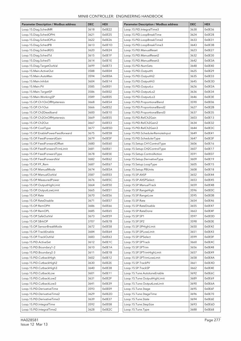
MINI8 CONTROLLER: ENGINEERING HANDBOOK
HA028581 Page 277 Issue 12 Mar 13
Parameter Description / Modbus address DEC HEX
Loop.15.Diag.SchedMR 3618 0x0E22
Loop.15.Diag.SchedOPHi 3621 0x0E25
Loop.15.Diag.SchedOPLo 3622 0x0E26
Loop.15.Diag.SchedPB 3613 0x0E1D
Loop.15.Diag.SchedR2G 3620 0x0E24
Loop.15.Diag.SchedTd 3615 0x0E1F
Loop.15.Diag.SchedTi 3614 0x0E1E
Loop.15.Diag.TargetOutVal 3699 0x0E73
Loop.15.Main.ActiveOut 3588 0x0E04
Loop.15.Main.AutoMan 3594 0x0E0A
Loop.15.Main.Inhibit 3604 0x0E14
Loop.15.Main.PV 3585 0x0E01
Loop.15.Main.TargetSP 3586 0x0E02
Loop.15.Main.WorkingSP 3589 0x0E05
Loop.15.OP.Ch1OnOffHysteresis 3668 0x0E54
Loop.15.OP.Ch1Out 3666 0x0E52
Loop.15.OP.Ch2Deadband 3600 0x0E10
Loop.15.OP.Ch2OnOffHysteresis 3669 0x0E55
Loop.15.OP.Ch2Out 3667 0x0E53
Loop.15.OP.CoolType 3677 0x0E5D
Loop.15.OP.EnablePowerFeedforward 3675 0x0E5B
Loop.15.OP.FeedForwardGain 3679 0x0E5F
Loop.15.OP.FeedForwardOffset 3680 0x0E60
Loop.15.OP.FeedForwardTrimLimit 3681 0x0E61
Loop.15.OP.FeedForwardType 3678 0x0E5E
Loop.15.OP.FeedForwardVal 3682 0x0E62
Loop.15.OP.FF_Rem 3687 0x0E67
Loop.15.OP.ManualMode 3674 0x0E5A
Loop.15.OP.ManualOutVal 3587 0x0E03
Loop.15.OP.MeasuredPower 3676 0x0E5C
Loop.15.OP.OutputHighLimit 3664 0x0E50
Loop.15.OP.OutputLowLimit 3665 0x0E51
Loop.15.OP.Rate 3670 0x0E56
Loop.15.OP.RateDisable 3671 0x0E57
Loop.15.OP.RemOPH 3686 0x0E66
Loop.15.OP.RemOPL 3685 0x0E65
Loop.15.OP.SafeOutVal 3673 0x0E59
Loop.15.OP.SBrkOP 3707 0x0E7B
Loop.15.OP.SensorBreakMode 3672 0x0E58
Loop.15.OP.TrackEnable 3684 0x0E64
Loop.15.OP.TrackOutVal 3683 0x0E63
Loop.15.PID.ActiveSet 3612 0x0E1C
Loop.15.PID.Boundary1-2 3610 0x0E1A
Loop.15.PID.Boundary2-3 3611 0x0E1B
Loop.15.PID.CutbackHigh 3602 0x0E12
Loop.15.PID.CutbackHigh2 3630 0x0E2E
Loop.15.PID.CutbackHigh3 3640 0x0E38
Loop.15.PID.CutbackLow 3601 0x0E11
Loop.15.PID.CutbackLow2 3631 0x0E2F
Loop.15.PID.CutbackLow3 3641 0x0E39
Loop.15.PID.DerivativeTime 3593 0x0E09
Loop.15.PID.DerivativeTime2 3629 0x0E2D
Loop.15.PID.DerivativeTime3 3639 0x0E37
Loop.15.PID.IntegralTime 3592 0x0E08
Loop.15.PID.IntegralTime2 3628 0x0E2C
Parameter Description / Modbus address DEC HEX
Loop.15.PID.IntegralTime3 3638 0x0E36
Loop.15.PID.LoopBreakTime 3624 0x0E28
Loop.15.PID.LoopBreakTime2 3633 0x0E31
Loop.15.PID.LoopBreakTime3 3643 0x0E3B
Loop.15.PID.ManualReset 3623 0x0E27
Loop.15.PID.ManualReset2 3632 0x0E30
Loop.15.PID.ManualReset3 3642 0x0E3A
Loop.15.PID.NumSets 3648 0x0E40
Loop.15.PID.OutputHi 3625 0x0E29
Loop.15.PID.OutputHi2 3635 0x0E33
Loop.15.PID.OutputHi3 3645 0x0E3D
Loop.15.PID.OutputLo 3626 0x0E2A
Loop.15.PID.OutputLo2 3636 0x0E34
Loop.15.PID.OutputLo3 3646 0x0E3E
Loop.15.PID.ProportionalBand 3590 0x0E06
Loop.15.PID.ProportionalBand2 3627 0x0E2B
Loop.15.PID.ProportionalBand3 3637 0x0E35
Loop.15.PID.RelCh2Gain 3603 0x0E13
Loop.15.PID.RelCh2Gain2 3634 0x0E32
Loop.15.PID.RelCh2Gain3 3644 0x0E3C
Loop.15.PID.SchedulerRemoteInput 3649 0x0E41
Loop.15.PID.SchedulerType 3647 0x0E3F
Loop.15.Setup.CH1ControlType 3606 0x0E16
Loop.15.Setup.CH2ControlType 3607 0x0E17
Loop.15.Setup.ControlAction 3591 0x0E07
Loop.15.Setup.DerivativeType 3609 0x0E19
Loop.15.Setup.LoopType 3605 0x0E15
Loop.15.Setup.PBUnits 3608 0x0E18
Loop.15.SP.AltSP 3652 0x0E44
Loop.15.SP.AltSPSelect 3653 0x0E45
Loop.15.SP.ManualTrack 3659 0x0E4B
Loop.15.SP.RangeHigh 3596 0x0E0C
Loop.15.SP.RangeLow 3595 0x0E0B
Loop.15.SP.Rate 3654 0x0E46
Loop.15.SP.RateDisable 3655 0x0E47
Loop.15.SP.RateDone 3663 0x0E4F
Loop.15.SP.SP1 3597 0x0E0D
Loop.15.SP.SP2 3598 0x0E0E
Loop.15.SP.SPHighLimit 3650 0x0E42
Loop.15.SP.SPLowLimit 3651 0x0E43
Loop.15.SP.SPSelect 3599 0x0E0F
Loop.15.SP.SPTrack 3660 0x0E4C
Loop.15.SP.SPTrim 3656 0x0E48
Loop.15.SP.SPTrimHighLimit 3657 0x0E49
Loop.15.SP.SPTrimLowLimit 3658 0x0E4A
Loop.15.SP.TrackPV 3661 0x0E4D
Loop.15.SP.TrackSP 3662 0x0E4E
Loop.15.Tune.AutotuneEnable 3692 0x0E6C
Loop.15.Tune.OutputHighLimit 3689 0x0E69
Loop.15.Tune.OutputLowLimit 3690 0x0E6A
Loop.15.Tune.Stage 3695 0x0E6F
Loop.15.Tune.StageTime 3696 0x0E70
Loop.15.Tune.State 3694 0x0E6E
Loop.15.Tune.StepSize 3693 0x0E6D
Loop.15.Tune.Type 3688 0x0E68

MINI8 CONTROLLER: ENGINEERING HANDBOOK
Page 278 HA028581 Issue 12 Mar 13
Parameter Description / Modbus address DEC HEX
Loop.16.Diag.DerivativeOutContrib 3959 0x0F77
Loop.16.Diag.Error 3953 0x0F71
Loop.16.Diag.IntegralOutContrib 3958 0x0F76
Loop.16.Diag.LoopBreakAlarm 3956 0x0F74
Loop.16.Diag.LoopMode 3954 0x0F72
Loop.16.Diag.PropOutContrib 3957 0x0F75
Loop.16.Diag.SBrk 3960 0x0F78
Loop.16.Diag.SchedCBH 3872 0x0F20
Loop.16.Diag.SchedCBL 3873 0x0F21
Loop.16.Diag.SchedLPBrk 3875 0x0F23
Loop.16.Diag.SchedMR 3874 0x0F22
Loop.16.Diag.SchedOPHi 3877 0x0F25
Loop.16.Diag.SchedOPLo 3878 0x0F26
Loop.16.Diag.SchedPB 3869 0x0F1D
Loop.16.Diag.SchedR2G 3876 0x0F24
Loop.16.Diag.SchedTd 3871 0x0F1F
Loop.16.Diag.SchedTi 3870 0x0F1E
Loop.16.Diag.TargetOutVal 3955 0x0F73
Loop.16.Main.ActiveOut 3844 0x0F04
Loop.16.Main.AutoMan 3850 0x0F0A
Loop.16.Main.Inhibit 3860 0x0F14
Loop.16.Main.PV 3841 0x0F01
Loop.16.Main.TargetSP 3842 0x0F02
Loop.16.Main.WorkingSP 3845 0x0F05
Loop.16.OP.Ch1OnOffHysteresis 3924 0x0F54
Loop.16.OP.Ch1Out 3922 0x0F52
Loop.16.OP.Ch2Deadband 3856 0x0F10
Loop.16.OP.Ch2OnOffHysteresis 3925 0x0F55
Loop.16.OP.Ch2Out 3923 0x0F53
Loop.16.OP.CoolType 3933 0x0F5D
Loop.16.OP.EnablePowerFeedforward 3931 0x0F5B
Loop.16.OP.FeedForwardGain 3935 0x0F5F
Loop.16.OP.FeedForwardOffset 3936 0x0F60
Loop.16.OP.FeedForwardTrimLimit 3937 0x0F61
Loop.16.OP.FeedForwardType 3934 0x0F5E
Loop.16.OP.FeedForwardVal 3938 0x0F62
Loop.16.OP.FF_Rem 3943 0x0F67
Loop.16.OP.ManualMode 3930 0x0F5A
Loop.16.OP.ManualOutVal 3843 0x0F03
Loop.16.OP.MeasuredPower 3932 0x0F5C
Loop.16.OP.OutputHighLimit 3920 0x0F50
Loop.16.OP.OutputLowLimit 3921 0x0F51
Loop.16.OP.Rate 3926 0x0F56
Loop.16.OP.RateDisable 3927 0x0F57
Loop.16.OP.RemOPH 3942 0x0F66
Loop.16.OP.RemOPL 3941 0x0F65
Loop.16.OP.SafeOutVal 3929 0x0F59
Loop.16.OP.SBrkOP 3963 0x0F7B
Loop.16.OP.SensorBreakMode 3928 0x0F58
Loop.16.OP.TrackEnable 3940 0x0F64
Loop.16.OP.TrackOutVal 3939 0x0F63
Loop.16.PID.ActiveSet 3868 0x0F1C
Loop.16.PID.Boundary1-2 3866 0x0F1A
Loop.16.PID.Boundary2-3 3867 0x0F1B
Loop.16.PID.CutbackHigh 3858 0x0F12
Loop.16.PID.CutbackHigh2 3886 0x0F2E
Parameter Description / Modbus address DEC HEX
Loop.16.PID.CutbackHigh3 3896 0x0F38
Loop.16.PID.CutbackLow 3857 0x0F11
Loop.16.PID.CutbackLow2 3887 0x0F2F
Loop.16.PID.CutbackLow3 3897 0x0F39
Loop.16.PID.DerivativeTime 3849 0x0F09
Loop.16.PID.DerivativeTime2 3885 0x0F2D
Loop.16.PID.DerivativeTime3 3895 0x0F37
Loop.16.PID.IntegralTime 3848 0x0F08
Loop.16.PID.IntegralTime2 3884 0x0F2C
Loop.16.PID.IntegralTime3 3894 0x0F36
Loop.16.PID.LoopBreakTime 3880 0x0F28
Loop.16.PID.LoopBreakTime2 3889 0x0F31
Loop.16.PID.LoopBreakTime3 3899 0x0F3B
Loop.16.PID.ManualReset 3879 0x0F27
Loop.16.PID.ManualReset2 3888 0x0F30
Loop.16.PID.ManualReset3 3898 0x0F3A
Loop.16.PID.NumSets 3904 0x0F40
Loop.16.PID.OutputHi 3881 0x0F29
Loop.16.PID.OutputHi2 3891 0x0F33
Loop.16.PID.OutputHi3 3901 0x0F3D
Loop.16.PID.OutputLo 3882 0x0F2A
Loop.16.PID.OutputLo2 3892 0x0F34
Loop.16.PID.OutputLo3 3902 0x0F3E
Loop.16.PID.ProportionalBand 3846 0x0F06
Loop.16.PID.ProportionalBand2 3883 0x0F2B
Loop.16.PID.ProportionalBand3 3893 0x0F35
Loop.16.PID.RelCh2Gain 3859 0x0F13
Loop.16.PID.RelCh2Gain2 3890 0x0F32
Loop.16.PID.RelCh2Gain3 3900 0x0F3C
Loop.16.PID.SchedulerRemoteInput 3905 0x0F41
Loop.16.PID.SchedulerType 3903 0x0F3F
Loop.16.Setup.CH1ControlType 3862 0x0F16
Loop.16.Setup.CH2ControlType 3863 0x0F17
Loop.16.Setup.ControlAction 3847 0x0F07
Loop.16.Setup.DerivativeType 3865 0x0F19
Loop.16.Setup.LoopType 3861 0x0F15
Loop.16.Setup.PBUnits 3864 0x0F18
Loop.16.SP.AltSP 3908 0x0F44
Loop.16.SP.AltSPSelect 3909 0x0F45
Loop.16.SP.ManualTrack 3915 0x0F4B
Loop.16.SP.RangeHigh 3852 0x0F0C
Loop.16.SP.RangeLow 3851 0x0F0B
Loop.16.SP.Rate 3910 0x0F46
Loop.16.SP.RateDisable 3911 0x0F47
Loop.16.SP.RateDone 3919 0x0F4F
Loop.16.SP.SP1 3853 0x0F0D
Loop.16.SP.SP2 3854 0x0F0E
Loop.16.SP.SPHighLimit 3906 0x0F42
Loop.16.SP.SPLowLimit 3907 0x0F43
Loop.16.SP.SPSelect 3855 0x0F0F
Loop.16.SP.SPTrack 3916 0x0F4C
Loop.16.SP.SPTrim 3912 0x0F48
Loop.16.SP.SPTrimHighLimit 3913 0x0F49
Loop.16.SP.SPTrimLowLimit 3914 0x0F4A
Loop.16.SP.TrackPV 3917 0x0F4D
Loop.16.SP.TrackSP 3918 0x0F4E

MINI8 CONTROLLER: ENGINEERING HANDBOOK
HA028581 Page 279 Issue 12 Mar 13
Parameter Description / Modbus address DEC HEX
Loop.16.Tune.AutotuneEnable 3948 0x0F6C
Loop.16.Tune.OutputHighLimit 3945 0x0F69
Loop.16.Tune.OutputLowLimit 3946 0x0F6A
Loop.16.Tune.Stage 3951 0x0F6F
Loop.16.Tune.StageTime 3952 0x0F70
Loop.16.Tune.State 3950 0x0F6E
Loop.16.Tune.StepSize 3949 0x0F6D
Loop.16.Tune.Type 3944 0x0F68
Math2.1.In1 4750 0x128e
Math2.1.In2 4751 0x128f
Math2.1.Out 4752 0x1290
Math2.2.In1 4753 0x1291
Math2.2.In2 4754 0x1292
Math2.2.Out 4755 0x1293
Math2.3.In1 4756 0x1294
Math2.3.In2 4757 0x1295
Math2.3.Out 4758 0x1296
Math2.4.In1 4759 0x1297
Math2.4.In2 4760 0x1298
Math2.4.Out 4761 0x1299
Math2.5.In1 4762 0x129a
Math2.5.In2 4763 0x129b
Math2.5.Out 4764 0x129c
Math2.6.In1 4765 0x129d
Math2.6.In2 4766 0x129e
Math2.6.Out 4767 0x129f
Math2.7.In1 4768 0x12a0
Math2.7.In2 4769 0x12a1
Math2.7.Out 4770 0x12a2
Math2.8.In1 4771 0x12a3
Math2.8.In2 4772 0x12a4
Math2.8.Out 4773 0x12a5
Math2.9.In1 4774 0x12a6
Math2.9.In2 4775 0x12a7
Math2.9.Out 4776 0x12a8
Math2.10.In1 4777 0x12a9
Math2.10.In2 4778 0x12aa
Math2.10.Out 4779 0x12ab
Math2.11.In1 4780 0x12ac
Math2.11.In2 4781 0x12ad
Math2.11.Out 4782 0x12ae
Math2.12.In1 4783 0x12af
Math2.12.In2 4784 0x12b0
Math2.12.Out 4785 0x12b1
Math2.13.In1 4786 0x12b2
Math2.13.In2 4787 0x12b3
Math2.13.Out 4788 0x12b4
Math2.14.In1 4789 0x12b5
Math2.14.In2 4790 0x12b6
Math2.14.Out 4791 0x12b7
Math2.15.In1 4792 0x12b8
Math2.15.In2 4793 0x12b9
Math2.15.Out 4794 0x12ba
Math2.16.In1 4795 0x12bb
Math2.16.In2 4796 0x12bc
Parameter Description / Modbus address DEC HEX
Math2.16.Out 4797 0x12bd
Math2.17.In1 4798 0x12be
Math2.17.In2 4799 0x12bf
Math2.17.Out 4800 0x12c0
Math2.18.In1 4801 0x12c1
Math2.18.In2 4802 0x12c2
Math2.18.Out 4803 0x12c3
Math2.19.In1 4804 0x12c4
Math2.19.In2 4805 0x12c5
Math2.19.Out 4806 0x12c6
Math2.20.In1 4807 0x12c7
Math2.20.In2 4808 0x12c8
Math2.20.Out 4809 0x12c9
Math2.21.In1 4810 0x12ca
Math2.21.In2 4811 0x12cb
Math2.21.Out 4812 0x12cc
Math2.22.In1 4813 0x12cd
Math2.22.In2 4814 0x12ce
Math2.22.Out 4815 0x12cf
Math2.23.In1 4816 0x12d0
Math2.23.In2 4817 0x12d1
Math2.23.Out 4818 0x12d2
Math2.24.In1 4819 0x12d3
Math2.24.In2 4820 0x12d4
Math2.24.Out 4821 0x12d5
MultiOper.1.AverageOut 5017 0x1399
MultiOper.1.In1 5006 0x138e
MultiOper.1.In2 5007 0x138f
MultiOper.1.In3 5008 0x1390
MultiOper.1.In4 5009 0x1391
MultiOper.1.In5 5010 0x1392
MultiOper.1.In6 5011 0x1393
MultiOper.1.In7 5012 0x1394
MultiOper.1.In8 5013 0x1395
MultiOper.1.MaxOut 5015 0x1397
MultiOper.1.MinOut 5016 0x1398
MultiOper.1.SumOut 5014 0x1396
MultiOper.2.AverageOut 5029 0x13a5
MultiOper.2.In1 5018 0x139a
MultiOper.2.In2 5019 0x139b
MultiOper.2.In3 5020 0x139c
MultiOper.2.In4 5021 0x139d
MultiOper.2.In5 5022 0x139e
MultiOper.2.In6 5023 0x139f
MultiOper.2.In7 5024 0x13a0
MultiOper.2.In8 5025 0x13a1
MultiOper.2.MaxOut 5027 0x13a3
MultiOper.2.MinOut 5028 0x13a4
MultiOper.2.SumOut 5026 0x13a2
MultiOper.3.AverageOut 5041 0x13b1
MultiOper.3.In1 5030 0x13a6
MultiOper.3.In2 5031 0x13a7
MultiOper.3.In3 5032 0x13a8
MultiOper.3.In4 5033 0x13a9
MultiOper.3.In5 5034 0x13aa

MINI8 CONTROLLER: ENGINEERING HANDBOOK
Page 280 HA028581 Issue 12 Mar 13
Parameter Description / Modbus address DEC HEX
MultiOper.3.In6 5035 0x13ab
MultiOper.3.In7 5036 0x13ac
MultiOper.3.In8 5037 0x13ad
MultiOper.3.MaxOut 5039 0x13af
MultiOper.3.MinOut 5040 0x13b0
MultiOper.3.SumOut 5038 0x13ae
MultiOper.4.AverageOut 5053 0x13bd
MultiOper.4.In1 5042 0x13b2
MultiOper.4.In2 5043 0x13b3
MultiOper.4.In3 5044 0x13b4
MultiOper.4.In4 5045 0x13b5
MultiOper.4.In5 5046 0x13b6
MultiOper.4.In6 5047 0x13b7
MultiOper.4.In7 5048 0x13b8
MultiOper.4.In8 5049 0x13b9
MultiOper.4.MaxOut 5051 0x13bb
MultiOper.4.MinOut 5052 0x13bc
MultiOper.4.SumOut 5050 0x13ba
Recipe.LastDataset 4913 0x1331
Recipe.LoadingStatus 4914 0x1332
Recipe.RecipeSelect 4912 0x1330
SwitchOver.SelectIn 4927 0x133f
SwitchOver.SwitchHigh 4925 0x133d
SwitchOver.SwitchLow 4926 0x133e
Timer.1.ElapsedTime 4995 0x1383
Timer.1.Out 4996 0x1384
Timer.1.Time 4994 0x1382
Timer.2.ElapsedTime 4998 0x1386
Timer.2.Out 4999 0x1387
Timer.2.Time 4997 0x1385
Timer.3.ElapsedTime 5001 0x1389
Timer.3.Out 5002 0x138A
Timer.3.Time 5000 0x1388
Timer.4.ElapsedTime 5004 0x138C
Timer.4.Out 5005 0x138D
Timer.4.Time 5003 0x138B
UsrVal.1.Val 4962 0x1362
UsrVal.2.Val 4963 0x1363
UsrVal.3.Val 4964 0x1364
UsrVal.4.Val 4965 0x1365
UsrVal.5.Val 4966 0x1366
UsrVal.6.Val 4967 0x1367
UsrVal.7.Val 4968 0x1368
UsrVal.8.Val 4969 0x1369
UsrVal.9.Val 4970 0x136a
UsrVal.10.Val 4971 0x136b
UsrVal.11.Val 4972 0x136c
UsrVal.12.Val 4973 0x136d
UsrVal.13.Val 4974 0x136e
UsrVal.14.Val 4975 0x136f
UsrVal.15.Val 4976 0x1370
UsrVal.16.Val 4977 0x1371
UsrVal.17.Val 4978 0x1372
UsrVal.18.Val 4979 0x1373
UsrVal.19.Val 4980 0x1374
UsrVal.20.Val 4981 0x1375
Parameter Description / Modbus address DEC HEX
UsrVal.21.Val 4982 0x1376
UsrVal.22.Val 4983 0x1377
UsrVal.23.Val 4984 0x1378
UsrVal.24.Val 4985 0x1379
UsrVal.25.Val 4986 0x137a
UsrVal.26.Val 4987 0x137b
UsrVal.27.Val 4988 0x137c
UsrVal.28.Val 4989 0x137d
UsrVal.29.Val 4990 0x137e
UsrVal.30.Val 4991 0x137f
UsrVal.31.Val 4992 0x1380
UsrVal.32.Val 4993 0x1381
Zirconia.1.CarbonPot 13256 0x33C8
Zirconia.1.CleanFreq 13251 0x33C3
Zirconia.1.CleanProbe 13248 0x33CO
Zirconia.1.CleanState 13268 0x33D4
Zirconia.1.CleanTime 13252 0x33C4
Zirconia.1.CleanValve 13263 0x33CF
Zirconia.1.DewPoint 13274 0x33DA
Zirconia.1.GasRef 13254 0x33C6
Zirconia.1.MaxRcovTime 13253 0x33C5
Zirconia.1.MinCalTemp 13270 0x33D6
Zirconia.1.MinRcovTime 13255 0x33C7
Zirconia.1.Oxygen 13261 0x33CD
Zirconia.1.OxygenExp 13260 0x33CC
Zirconia.1.ProbeFault 13271 0x33D7
Zirconia.1.ProbeInput 13259 0x33CB
Zirconia.1.ProbeOffset 13250 0x33C2
Zirconia.1.ProbeStatus 13262 0x33CE
Zirconia.1.ProbeType 13258 0x33CA
Zirconia.1.ProcFactor 13275 0x33DB
Zirconia.1.PVFrozen 13272 0x33D8
Zirconia.1.RemGasEn 13257 0x33C9
Zirconia.1.RemGasRef 13267 0x33D3
Zirconia.1.Resolution 13273 0x33D9
Zirconia.1.SootAlm 13264 0x33D0
Zirconia.1.TempInput 13269 0x33D5
Zirconia.1.TempOffset 13266 0x33D2
Zirconia.1.Time2Clean 13249 0x33C1
Zirconia.1.Tolerence 13276 0x33DC
Zirconia.1.WrkGas 13265 0x33D1
Zirconia.2.CarbonPot 13288 0x33E8
Zirconia.2.CleanFreq 13283 0x33E3
Zirconia.2.CleanProbe 13280 0x33EO
Zirconia.2.CleanState 13300 0x33F4
Zirconia.2.CleanTime 13284 0x33E4
Zirconia.2.CleanValve 13295 0x33EF
Zirconia.2.DewPoint 13306 0x33FA
Zirconia.2.GasRef 13286 0x33E6
Zirconia.2.MaxRcovTime 13285 0x33E5
Zirconia.2.MinCalTemp 13302 0x33F6
Zirconia.2.MinRcovTime 13287 0x33E7
Zirconia.2.Oxygen 13293 0x33ED
Zirconia.2.OxygenExp 13292 0x33EC
Zirconia.2.ProbeFault 13303 0x33F7
Zirconia.2.ProbeInput 13291 0x33EB

MINI8 CONTROLLER: ENGINEERING HANDBOOK
HA028581 Page 281 Issue 12 Mar 13
Parameter Description / Modbus address DEC HEX
Zirconia.2.ProbeOffset 13282 0x33E2
Zirconia.2.ProbeStatus 13294 0x33EE
Zirconia.2.ProbeType 13290 0x33EA
Zirconia.2.ProcFactor 13307 0x33FB
Zirconia.2.PVFrozen 13304 0x33F8
Zirconia.2.RemGasEn 13289 0x33E9
Zirconia.2.RemGasRef 13299 0x33F3
Zirconia.2.Resolution 13305 0x33F9
Zirconia.2.SootAlm 13296 0x33F0
Zirconia.2.TempInput 13301 0x33F5
Zirconia.2.TempOffset 13298 0x33F2
Zirconia.2.Time2Clean 13281 0x33E1
Zirconia.2.Tolerence 13308 0x33FC
Zirconia.2.WrkGas 13297 0x33F1

MINI8 CONTROLLER: ENGINEERING HANDBOOK
Page 282 HA028581 Issue 12 Mar 13
24.2.1 Programmer Address Ranges - Decimal The following table shows the addresses set aside for programmers.
PROGRAM NUMBER DECIMAL ADDRESSES (2.xx) 1 2 3 4 5 6 7 8
Comms.n.ProgramNumber 5568 5632 5696 5760 5824 5888 5952 6016
Program.n.HoldbackVal 5569 5633 5697 5761 5825 5889 5953 6017
Program.n.RampUnits 5570 5634 5698 5762 5826 5890 5954 6018
Program.n.DwellUnits 5571 5635 5699 5763 5827 5891 5955 6019
Program.n.Cycles 5572 5636 5700 5764 5828 5892 5956 6020
Programmer.n.PowerFailAct 5573 5637 5701 5765 5829 5893 5957 6021
Programmer.n.Servo 5574 5638 5702 5766 5830 5894 5958 6022
Programmer.n.SyncMode 5575 5639 5703 5767 5831 5895 5959 6023
Programmer.n.ResetEventOuts 5576 5640 5704 5768 5832 5896 5960 6024
Programmer.n.CurProg 5577 5641 5705 5769 5833 5897 5961 6025
Programmer.n.CurSeg 5578 5642 5706 5770 5834 5898 5962 6026
Programmer.n.ProgStatus 5579 5643 5707 5771 5835 5899 5963 6027
Programmer.n.PSP 5580 5644 5708 5772 5836 5900 5964 6028
Programmer.n.CyclesLeft 5581 5645 5709 5773 5837 5901 5965 6029
Programmer.n.CurSegType 5582 5646 5710 5774 5838 5902 5966 6030
Programmer.n.SegTarget 5583 5647 5711 5775 5839 5903 5967 6031
Programmer.n.SegRate 5584 5648 5712 5776 5840 5904 5968 6032
Programmer.n.ProgTimeLeft 5585 5649 5713 5777 5841 5905 5969 6033
Programmer.n.PVIn 5586 5650 5714 5778 5842 5906 5970 6034
Programmer.n.SPIn 5587 5651 5715 5779 5843 5907 5971 6035
Programmer.n.EventOuts 5588 5652 5716 5780 5844 5908 5972 6036
Programmer.n.SegTimeLeft 5589 5653 5717 5781 5845 5909 5973 6037
Programmer.n.EndOfSeg 5590 5654 5718 5782 5846 5910 5974 6038
Programmer.n.SyncIn 5591 5655 5719 5783 5847 5911 5975 6039
Programmer.n.FastRun 5592 5656 5720 5784 5848 5912 5976 6040
Programmer.n.AdvSeg 5593 5657 5721 5785 5849 5913 5977 6041
Programmer.n.SkipSeg 5594 5658 5722 5786 5850 5914 5978 6042
Program.n.PVStart 5597 5661 5725 5789 5853 5917 5981 6045
Programmer.n.PrgIn1 5602 5666 5730 5794 5858 5922 5986 6050
Programmer.n.PrgIn2 5603 5667 5731 5795 5859 5923 5987 6051
Programmer.n.PVWaitIP 5604 5668 5732 5796 5860 5924 5988 6052
Programmer.n.ProgError 5605 5669 5733 5797 5861 5925 5989 6053
Programmer.n.PVEventOP 5606 5670 5734 5798 5862 5926 5990 6054
Programmer.n.GoBackCyclesLeft 5645 5709 5773 5837 5901 5965 6029 6093
Programmer.n.DelayTime 5685 5749 5813 5877 5941 6005 6069 6133
Programmer.n.ProgReset 5726 5790 5854 5918 5982 6046 6110 6174
Programmer.n.ProgRun 5768 5832 5896 5960 6024 6088 6152 6216
Programmer.n.ProgHold 5811 5875 5939 6003 6067 6131 6195 6259
Programmer.n.ProgRunHold 5855 5919 5983 6047 6111 6175 6239 6303
Programmer.n.ProgRunReset 5900 5964 6028 6092 6156 6220 6284 6348
Segment.1.Type 6080 6592 7104 7616 8128 8640 9152 9664
Segment.1.Holdback 6081 6593 7105 7617 8129 8641 9153 9665
Segment.1.Duration 6084 6596 7108 7620 8132 8644 9156 9668
Segment.1.RampRate 6085 6597 7109 7621 8133 8645 9157 9669
Segment.1.TargetSP 6086 6598 7110 7622 8134 8646 9158 9670
Segment.1.EndAction 6087 6599 7111 7623 8135 8647 9159 9671
Segment.1.EventOutputs 6088 6600 7112 7624 8136 8648 9160 9672
Segment.1.WaitFor 6089 6601 7113 7625 8137 8649 9161 9673
6090 6602 7114 7626 8138 8650 9162 9674
Segment.1.PVEvent 6093 6605 7117 7629 8141 8653 9165 9677
Segment.1.PVThreshold 6094 6606 7118 7630 8142 8654 9166 9678
Segment.1.UserVal 6095 6607 7119 7631 8143 8655 9167 9679
Segment.1.GsoakType 6096 6608 7120 7632 8144 8656 9168 9680
Segment.1.GsoakVal 6097 6609 7121 7633 8145 8657 9169 9681
Segment.1.TimeEvent 6098 6610 7122 7634 8146 8658 9170 9682

MINI8 CONTROLLER: ENGINEERING HANDBOOK
HA028581 Page 283 Issue 12 Mar 13
PROGRAM NUMBER DECIMAL ADDRESSES (2.xx) 1 2 3 4 5 6 7 8
Segment.1.OnTime 6099 6611 7123 7635 8147 8659 9171 9683
Segment.1.OffTime 6100 6612 7124 7636 8148 8660 9172 9684
Segment.1.PIDSet 6101 6613 7125 7637 8149 8661 9173 9685
Segment.1.PVWait 6102 6614 7126 7638 8150 8662 9174 9686
Segment.1.WaitVal 6103 6615 7127 7639 8151 8663 9175 9687
Segment.2.Type 6112 6624 7136 7648 8160 8672 9184 9696
Segment.2.Holdback 6113 6625 7137 7649 8161 8673 9185 9697
Segment.2.Duration 6116 6628 7140 7652 8164 8676 9188 9700
Segment.2.RampRate 6117 6629 7141 7653 8165 8677 9189 9701
Segment.2.TargetSP 6118 6630 7142 7654 8166 8678 9190 9702
Segment.2.EndAction 6119 6631 7143 7655 8167 8679 9191 9703
Segment.2.EventOutputs 6120 6632 7144 7656 8168 8680 9192 9704
Segment.2.WaitFor 6121 6633 7145 7657 8169 8681 9193 9705
6122 6634 7146 7658 8170 8682 9194 9706
Segment.2.GobackSeg 6123 6635 7147 7659 8171 8683 9195 9707
Segment.2.GobackCycles 6124 6636 7148 7660 8172 8684 9196 9708
Segment.2.PVEvent 6125 6637 7149 7661 8173 8685 9197 9709
Segment.2.PVThreshold 6126 6638 7150 7662 8174 8686 9198 9710
Segment.2.UserVal 6127 6639 7151 7663 8175 8687 9199 9711
Segment.2.GsoakType 6128 6640 7152 7664 8176 8688 9200 9712
Segment.2.GsoakVal 6129 6641 7153 7665 8177 8689 9201 9713
Segment.2.TimeEvent 6130 6642 7154 7666 8178 8690 9202 9714
Segment.2.OnTime 6131 6643 7155 7667 8179 8691 9203 9715
Segment.2.OffTime 6132 6644 7156 7668 8180 8692 9204 9716
Segment.2.PIDSet 6133 6645 7157 7669 8181 8693 9205 9717
Segment.2.PVWait 6134 6646 7158 7670 8182 8694 9206 9718
Segment.2.WaitVal 6135 6647 7159 7671 8183 8695 9207 9719
Segment.3.Type 6144 6656 7168 7680 8192 8704 9216 9728
Segment.3.Holdback 6145 6657 7169 7681 8193 8705 9217 9729
Segment.3.Duration 6148 6660 7172 7684 8196 8708 9220 9732
Segment.3.RampRate 6149 6661 7173 7685 8197 8709 9221 9733
Segment.3.TargetSP 6150 6662 7174 7686 8198 8710 9222 9734
Segment.3.EndAction 6151 6663 7175 7687 8199 8711 9223 9735
Segment.3.EventOutputs 6152 6664 7176 7688 8200 8712 9224 9736
Segment.3.WaitFor 6153 6665 7177 7689 8201 8713 9225 9737
6154 6666 7178 7690 8202 8714 9226 9738
Segment.3.GobackSeg 6155 6667 7179 7691 8203 8715 9227 9739
Segment.3.GobackCycles 6156 6668 7180 7692 8204 8716 9228 9740
Segment.3.PVEvent 6157 6669 7181 7693 8205 8717 9229 9741
Segment.3.PVThreshold 6158 6670 7182 7694 8206 8718 9230 9742
Segment.3.UserVal 6159 6671 7183 7695 8207 8719 9231 9743
Segment.3.GsoakType 6160 6672 7184 7696 8208 8720 9232 9744
Segment.3.GsoakVal 6161 6673 7185 7697 8209 8721 9233 9745
Segment.3.TimeEvent 6162 6674 7186 7698 8210 8722 9234 9746
Segment.3.OnTime 6163 6675 7187 7699 8211 8723 9235 9747
Segment.3.OffTime 6164 6676 7188 7700 8212 8724 9236 9748
Segment.3.PIDSet 6165 6677 7189 7701 8213 8725 9237 9749
Segment.3.PVWait 6166 6678 7190 7702 8214 8726 9238 9750
Segment.3.WaitVal 6167 6679 7191 7703 8215 8727 9239 9751
Segment.4.Type 6176 6688 7200 7712 8224 8736 9248 9760
Segment.4.Holdback 6177 6689 7201 7713 8225 8737 9249 9761
Segment.4.Duration 6180 6692 7204 7716 8228 8740 9252 9764
Segment.4.RampRate 6181 6693 7205 7717 8229 8741 9253 9765
Segment.4.TargetSP 6182 6694 7206 7718 8230 8742 9254 9766
Segment.4.EndAction 6183 6695 7207 7719 8231 8743 9255 9767
Segment.4.EventOutputs 6184 6696 7208 7720 8232 8744 9256 9768

MINI8 CONTROLLER: ENGINEERING HANDBOOK
Page 284 HA028581 Issue 12 Mar 13
PROGRAM NUMBER DECIMAL ADDRESSES (2.xx) 1 2 3 4 5 6 7 8
Segment.4.WaitFor 6185 6697 7209 7721 8233 8745 9257 9769
6186 6698 7210 7722 8234 8746 9258 9770
Segment.4.GobackSeg 6187 6699 7211 7723 8235 8747 9259 9771
Segment.4.GobackCycles 6188 6700 7212 7724 8236 8748 9260 9772
Segment.4.PVEvent 6189 6701 7213 7725 8237 8749 9261 9773
Segment.4.PVThreshold 6190 6702 7214 7726 8238 8750 9262 9774
Segment.4.UserVal 6191 6703 7215 7727 8239 8751 9263 9775
Segment.4.GsoakType 6192 6704 7216 7728 8240 8752 9264 9776
Segment.4.GsoakVal 6193 6705 7217 7729 8241 8753 9265 9777
Segment.4.TimeEvent 6194 6706 7218 7730 8242 8754 9266 9778
Segment.4.OnTime 6195 6707 7219 7731 8243 8755 9267 9779
Segment.4.OffTime 6196 6708 7220 7732 8244 8756 9268 9780
Segment.4.PIDSet 6197 6709 7221 7733 8245 8757 9269 9781
Segment.4.PVWait 6198 6710 7222 7734 8246 8758 9270 9782
Segment.4.WaitVal 6199 6711 7223 7735 8247 8759 9271 9783
Segment.5.Type 6208 6720 7232 7744 8256 8768 9280 9792
Segment.5.Holdback 6209 6721 7233 7745 8257 8769 9281 9793
Segment.5.Duration 6212 6724 7236 7748 8260 8772 9284 9796
Segment.5.RampRate 6213 6725 7237 7749 8261 8773 9285 9797
Segment.5.TargetSP 6214 6726 7238 7750 8262 8774 9286 9798
Segment.5.EndAction 6215 6727 7239 7751 8263 8775 9287 9799
Segment.5.EventOutputs 6216 6728 7240 7752 8264 8776 9288 9800
Segment.5.WaitFor 6217 6729 7241 7753 8265 8777 9289 9801
6218 6730 7242 7754 8266 8778 9290 9802
Segment.5.GobackSeg 6219 6731 7243 7755 8267 8779 9291 9803
Segment.5.GobackCycles 6220 6732 7244 7756 8268 8780 9292 9804
Segment.5.PVEvent 6221 6733 7245 7757 8269 8781 9293 9805
Segment.5.PVThreshold 6222 6734 7246 7758 8270 8782 9294 9806
Segment.5.UserVal 6223 6735 7247 7759 8271 8783 9295 9807
Segment.5.GsoakType 6224 6736 7248 7760 8272 8784 9296 9808
Segment.5.GsoakVal 6225 6737 7249 7761 8273 8785 9297 9809
Segment.5.TimeEvent 6226 6738 7250 7762 8274 8786 9298 9810
Segment.5.OnTime 6227 6739 7251 7763 8275 8787 9299 9811
Segment.5.OffTime 6228 6740 7252 7764 8276 8788 9300 9812
Segment.5.PIDSet 6229 6741 7253 7765 8277 8789 9301 9813
Segment.5.PVWait 6230 6742 7254 7766 8278 8790 9302 9814
Segment.5.WaitVal 6231 6743 7255 7767 8279 8791 9303 9815
Segment.6.Type 6240 6752 7264 7776 8288 8800 9312 9824
Segment.6.Holdback 6241 6753 7265 7777 8289 8801 9313 9825
Segment.6.Duration 6244 6756 7268 7780 8292 8804 9316 9828
Segment.6.RampRate 6245 6757 7269 7781 8293 8805 9317 9829
Segment.6.TargetSP 6246 6758 7270 7782 8294 8806 9318 9830
Segment.6.EndAction 6247 6759 7271 7783 8295 8807 9319 9831
Segment.6.EventOutputs 6248 6760 7272 7784 8296 8808 9320 9832
Segment.6.WaitFor 6249 6761 7273 7785 8297 8809 9321 9833
6250 6762 7274 7786 8298 8810 9322 9834
Segment.6.GobackSeg 6251 6763 7275 7787 8299 8811 9323 9835
Segment.6.GobackCycles 6252 6764 7276 7788 8300 8812 9324 9836
Segment.6.PVEvent 6253 6765 7277 7789 8301 8813 9325 9837
Segment.6.PVThreshold 6254 6766 7278 7790 8302 8814 9326 9838
Segment.6.UserVal 6255 6767 7279 7791 8303 8815 9327 9839
Segment.6.GsoakType 6256 6768 7280 7792 8304 8816 9328 9840
Segment.6.GsoakVal 6257 6769 7281 7793 8305 8817 9329 9841
Segment.6.TimeEvent 6258 6770 7282 7794 8306 8818 9330 9842
Segment.6.OnTime 6259 6771 7283 7795 8307 8819 9331 9843
Segment.6.OffTime 6260 6772 7284 7796 8308 8820 9332 9844
Segment.6.PIDSet 6261 6773 7285 7797 8309 8821 9333 9845

MINI8 CONTROLLER: ENGINEERING HANDBOOK
HA028581 Page 285 Issue 12 Mar 13
PROGRAM NUMBER DECIMAL ADDRESSES (2.xx) 1 2 3 4 5 6 7 8
Segment.6.PVWait 6262 6774 7286 7798 8310 8822 9334 9846
Segment.6.WaitVal 6263 6775 7287 7799 8311 8823 9335 9847
Segment.7.Type 6272 6784 7296 7808 8320 8832 9344 9856
Segment.7.Holdback 6273 6785 7297 7809 8321 8833 9345 9857
Segment.7.Duration 6276 6788 7300 7812 8324 8836 9348 9860
Segment.7.RampRate 6277 6789 7301 7813 8325 8837 9349 9861
Segment.7.TargetSP 6278 6790 7302 7814 8326 8838 9350 9862
Segment.7.EndAction 6279 6791 7303 7815 8327 8839 9351 9863
Segment.7.EventOutputs 6280 6792 7304 7816 8328 8840 9352 9864
Segment.7.WaitFor 6281 6793 7305 7817 8329 8841 9353 9865
6282 6794 7306 7818 8330 8842 9354 9866
Segment.7.GobackSeg 6283 6795 7307 7819 8331 8843 9355 9867
Segment.7.GobackCycles 6284 6796 7308 7820 8332 8844 9356 9868
Segment.7.PVEvent 6285 6797 7309 7821 8333 8845 9357 9869
Segment.7.PVThreshold 6286 6798 7310 7822 8334 8846 9358 9870
Segment.7.UserVal 6287 6799 7311 7823 8335 8847 9359 9871
Segment.7.GsoakType 6288 6800 7312 7824 8336 8848 9360 9872
Segment.7.GsoakVal 6289 6801 7313 7825 8337 8849 9361 9873
Segment.7.TimeEvent 6290 6802 7314 7826 8338 8850 9362 9874
Segment.7.OnTime 6291 6803 7315 7827 8339 8851 9363 9875
Segment.7.OffTime 6292 6804 7316 7828 8340 8852 9364 9876
Segment.7.PIDSet 6293 6805 7317 7829 8341 8853 9365 9877
Segment.7.PVWait 6294 6806 7318 7830 8342 8854 9366 9878
Segment.7.WaitVal 6295 6807 7319 7831 8343 8855 9367 9879
Segment.8.Type 6304 6816 7328 7840 8352 8864 9376 9888
Segment.8.Holdback 6305 6817 7329 7841 8353 8865 9377 9889
Segment.8.Duration 6308 6820 7332 7844 8356 8868 9380 9892
Segment.8.RampRate 6309 6821 7333 7845 8357 8869 9381 9893
Segment.8.TargetSP 6310 6822 7334 7846 8358 8870 9382 9894
Segment.8.EndAction 6311 6823 7335 7847 8359 8871 9383 9895
Segment.8.EventOutputs 6312 6824 7336 7848 8360 8872 9384 9896
Segment.8.WaitFor 6313 6825 7337 7849 8361 8873 9385 9897
6314 6826 7338 7850 8362 8874 9386 9898
Segment.8.GobackSeg 6315 6827 7339 7851 8363 8875 9387 9899
Segment.8.GobackCycles 6316 6828 7340 7852 8364 8876 9388 9900
Segment.8.PVEvent 6317 6829 7341 7853 8365 8877 9389 9901
Segment.8.PVThreshold 6318 6830 7342 7854 8366 8878 9390 9902
Segment.8.UserVal 6319 6831 7343 7855 8367 8879 9391 9903
Segment.8.GsoakType 6320 6832 7344 7856 8368 8880 9392 9904
Segment.8.GsoakVal 6321 6833 7345 7857 8369 8881 9393 9905
Segment.8.TimeEvent 6322 6834 7346 7858 8370 8882 9394 9906
Segment.8.OnTime 6323 6835 7347 7859 8371 8883 9395 9907
Segment.8.OffTime 6324 6836 7348 7860 8372 8884 9396 9908
Segment.8.PIDSet 6325 6837 7349 7861 8373 8885 9397 9909
Segment.8.PVWait 6326 6838 7350 7862 8374 8886 9398 9910
Segment.8.WaitVal 6327 6839 7351 7863 8375 8887 9399 9911
Segment.9.Type 6336 6848 7360 7872 8384 8896 9408 9920
Segment.9.Holdback 6337 6849 7361 7873 8385 8897 9409 9921
Segment.9.Duration 6340 6852 7364 7876 8388 8900 9412 9924
Segment.9.RampRate 6341 6853 7365 7877 8389 8901 9413 9925
Segment.9.TargetSP 6342 6854 7366 7878 8390 8902 9414 9926
Segment.9.EndAction 6343 6855 7367 7879 8391 8903 9415 9927
Segment.9.EventOutputs 6344 6856 7368 7880 8392 8904 9416 9928
Segment.9.WaitFor 6345 6857 7369 7881 8393 8905 9417 9929
6346 6858 7370 7882 8394 8906 9418 9930
Segment.9.GobackSeg 6347 6859 7371 7883 8395 8907 9419 9931

MINI8 CONTROLLER: ENGINEERING HANDBOOK
Page 286 HA028581 Issue 12 Mar 13
PROGRAM NUMBER DECIMAL ADDRESSES (2.xx) 1 2 3 4 5 6 7 8
Segment.9.GobackCycles 6348 6860 7372 7884 8396 8908 9420 9932
Segment.9.PVEvent 6349 6861 7373 7885 8397 8909 9421 9933
Segment.9.PVThreshold 6350 6862 7374 7886 8398 8910 9422 9934
Segment.9.UserVal 6351 6863 7375 7887 8399 8911 9423 9935
Segment.9.GsoakType 6352 6864 7376 7888 8400 8912 9424 9936
Segment.9.GsoakVal 6353 6865 7377 7889 8401 8913 9425 9937
Segment.9.TimeEvent 6354 6866 7378 7890 8402 8914 9426 9938
Segment.9.OnTime 6355 6867 7379 7891 8403 8915 9427 9939
Segment.9.OffTime 6356 6868 7380 7892 8404 8916 9428 9940
Segment.9.PIDSet 6357 6869 7381 7893 8405 8917 9429 9941
Segment.9.PVWait 6358 6870 7382 7894 8406 8918 9430 9942
Segment.9.WaitVal 6359 6871 7383 7895 8407 8919 9431 9943
Segment.10.Type 6368 6880 7392 7904 8416 8928 9440 9952
Segment.10.Holdback 6369 6881 7393 7905 8417 8929 9441 9953
Segment.10.Duration 6372 6884 7396 7908 8420 8932 9444 9956
Segment.10.RampRate 6373 6885 7397 7909 8421 8933 9445 9957
Segment.10.TargetSP 6374 6886 7398 7910 8422 8934 9446 9958
Segment.10.EndAction 6375 6887 7399 7911 8423 8935 9447 9959
Segment.10.EventOutputs 6376 6888 7400 7912 8424 8936 9448 9960
Segment.10.WaitFor 6377 6889 7401 7913 8425 8937 9449 9961
6378 6890 7402 7914 8426 8938 9450 9962
Segment.10.GobackSeg 6379 6891 7403 7915 8427 8939 9451 9963
Segment.10.GobackCycles 6380 6892 7404 7916 8428 8940 9452 9964
Segment.10.PVEvent 6381 6893 7405 7917 8429 8941 9453 9965
Segment.10.PVThreshold 6382 6894 7406 7918 8430 8942 9454 9966
Segment.10.UserVal 6383 6895 7407 7919 8431 8943 9455 9967
Segment.10.GsoakType 6384 6896 7408 7920 8432 8944 9456 9968
Segment.10.GsoakVal 6385 6897 7409 7921 8433 8945 9457 9969
Segment.10.TimeEvent 6386 6898 7410 7922 8434 8946 9458 9970
Segment.10.OnTime 6387 6899 7411 7923 8435 8947 9459 9971
Segment.10.OffTime 6388 6900 7412 7924 8436 8948 9460 9972
Segment.10.PIDSet 6389 6901 7413 7925 8437 8949 9461 9973
Segment.10.PVWait 6390 6902 7414 7926 8438 8950 9462 9974
Segment.10.WaitVal 6391 6903 7415 7927 8439 8951 9463 9975
Segment.11.Type 6400 6912 7424 7936 8448 8960 9472 9984
Segment.11.Holdback 6401 6913 7425 7937 8449 8961 9473 9985
Segment.11.Duration 6404 6916 7428 7940 8452 8964 9476 9988
Segment.11.RampRate 6405 6917 7429 7941 8453 8965 9477 9989
Segment.11.TargetSP 6406 6918 7430 7942 8454 8966 9478 9990
Segment.11.EndAction 6407 6919 7431 7943 8455 8967 9479 9991
Segment.11.EventOutputs 6408 6920 7432 7944 8456 8968 9480 9992
Segment.11.WaitFor 6409 6921 7433 7945 8457 8969 9481 9993
6410 6922 7434 7946 8458 8970 9482 9994
Segment.11.GobackSeg 6411 6923 7435 7947 8459 8971 9483 9995
Segment.11.GobackCycles 6412 6924 7436 7948 8460 8972 9484 9996
Segment.11.PVEvent 6413 6925 7437 7949 8461 8973 9485 9997
Segment.11.PVThreshold 6414 6926 7438 7950 8462 8974 9486 9998
Segment.11.UserVal 6415 6927 7439 7951 8463 8975 9487 9999
Segment.11.GsoakType 6416 6928 7440 7952 8464 8976 9488 10000
Segment.11.GsoakVal 6417 6929 7441 7953 8465 8977 9489 10001
Segment.11.TimeEvent 6418 6930 7442 7954 8466 8978 9490 10002
Segment.11.OnTime 6419 6931 7443 7955 8467 8979 9491 10003
Segment.11.OffTime 6420 6932 7444 7956 8468 8980 9492 10004
Segment.11.PIDSet 6421 6933 7445 7957 8469 8981 9493 10005
Segment.11.PVWait 6422 6934 7446 7958 8470 8982 9494 10006
Segment.11.WaitVal 6423 6935 7447 7959 8471 8983 9495 10007
Segment.12.Type 6432 6944 7456 7968 8480 8992 9504 10016

MINI8 CONTROLLER: ENGINEERING HANDBOOK
HA028581 Page 287 Issue 12 Mar 13
PROGRAM NUMBER DECIMAL ADDRESSES (2.xx) 1 2 3 4 5 6 7 8
Segment.12.Holdback 6433 6945 7457 7969 8481 8993 9505 10017
Segment.12.Duration 6436 6948 7460 7972 8484 8996 9508 10020
Segment.12.RampRate 6437 6949 7461 7973 8485 8997 9509 10021
Segment.12.TargetSP 6438 6950 7462 7974 8486 8998 9510 10022
Segment.12.EndAction 6439 6951 7463 7975 8487 8999 9511 10023
Segment.12.EventOutputs 6440 6952 7464 7976 8488 9000 9512 10024
Segment.12.WaitFor 6441 6953 7465 7977 8489 9001 9513 10025
6442 6954 7466 7978 8490 9002 9514 10026
Segment.12.GobackSeg 6443 6955 7467 7979 8491 9003 9515 10027
Segment.12.GobackCycles 6444 6956 7468 7980 8492 9004 9516 10028
Segment.12.PVEvent 6445 6957 7469 7981 8493 9005 9517 10029
Segment.12.PVThreshold 6446 6958 7470 7982 8494 9006 9518 10030
Segment.12.UserVal 6447 6959 7471 7983 8495 9007 9519 10031
Segment.12.GsoakType 6448 6960 7472 7984 8496 9008 9520 10032
Segment.12.GsoakVal 6449 6961 7473 7985 8497 9009 9521 10033
Segment.12.TimeEvent 6450 6962 7474 7986 8498 9010 9522 10034
Segment.12.OnTime 6451 6963 7475 7987 8499 9011 9523 10035
Segment.12.OffTime 6452 6964 7476 7988 8500 9012 9524 10036
Segment.12.PIDSet 6453 6965 7477 7989 8501 9013 9525 10037
Segment.12.PVWait 6454 6966 7478 7990 8502 9014 9526 10038
Segment.12.WaitVal 6455 6967 7479 7991 8503 9015 9527 10039
Segment.13.Type 6464 6976 7488 8000 8512 9024 9536 10048
Segment.13.Holdback 6465 6977 7489 8001 8513 9025 9537 10049
Segment.13.Duration 6468 6980 7492 8004 8516 9028 9540 10052
Segment.13.RampRate 6469 6981 7493 8005 8517 9029 9541 10053
Segment.13.TargetSP 6470 6982 7494 8006 8518 9030 9542 10054
Segment.13.EndAction 6471 6983 7495 8007 8519 9031 9543 10055
Segment.13.EventOutputs 6472 6984 7496 8008 8520 9032 9544 10056
Segment.13.WaitFor 6473 6985 7497 8009 8521 9033 9545 10057
6474 6986 7498 8010 8522 9034 9546 10058
Segment.13.GobackSeg 6475 6987 7499 8011 8523 9035 9547 10059
Segment.13.GobackCycles 6476 6988 7500 8012 8524 9036 9548 10060
Segment.13.PVEvent 6477 6989 7501 8013 8525 9037 9549 10061
Segment.13.PVThreshold 6478 6990 7502 8014 8526 9038 9550 10062
Segment.13.UserVal 6479 6991 7503 8015 8527 9039 9551 10063
Segment.13.GsoakType 6480 6992 7504 8016 8528 9040 9552 10064
Segment.13.GsoakVal 6481 6993 7505 8017 8529 9041 9553 10065
Segment.13.TimeEvent 6482 6994 7506 8018 8530 9042 9554 10066
Segment.13.OnTime 6483 6995 7507 8019 8531 9043 9555 10067
Segment.13.OffTime 6484 6996 7508 8020 8532 9044 9556 10068
Segment.13.PIDSet 6485 6997 7509 8021 8533 9045 9557 10069
Segment.13.PVWait 6486 6998 7510 8022 8534 9046 9558 10070
Segment.13.WaitVal 6487 6999 7511 8023 8535 9047 9559 10071
Segment.14.Type 6496 7008 7520 8032 8544 9056 9568 10080
Segment.14.Holdback 6497 7009 7521 8033 8545 9057 9569 10081
Segment.14.Duration 6500 7012 7524 8036 8548 9060 9572 10084
Segment.14.RampRate 6501 7013 7525 8037 8549 9061 9573 10085
Segment.14.TargetSP 6502 7014 7526 8038 8550 9062 9574 10086
Segment.14.EndAction 6503 7015 7527 8039 8551 9063 9575 10087
Segment.14.EventOutputs 6504 7016 7528 8040 8552 9064 9576 10088
Segment.14.WaitFor 6505 7017 7529 8041 8553 9065 9577 10089
6506 7018 7530 8042 8554 9066 9578 10090
Segment.14.GobackSeg 6507 7019 7531 8043 8555 9067 9579 10091
Segment.14.GobackCycles 6508 7020 7532 8044 8556 9068 9580 10092
Segment.14.PVEvent 6509 7021 7533 8045 8557 9069 9581 10093
Segment.14.PVThreshold 6510 7022 7534 8046 8558 9070 9582 10094

MINI8 CONTROLLER: ENGINEERING HANDBOOK
Page 288 HA028581 Issue 12 Mar 13
PROGRAM NUMBER DECIMAL ADDRESSES (2.xx) 1 2 3 4 5 6 7 8
Segment.14.UserVal 6511 7023 7535 8047 8559 9071 9583 10095
Segment.14.GsoakType 6512 7024 7536 8048 8560 9072 9584 10096
Segment.14.GsoakVal 6513 7025 7537 8049 8561 9073 9585 10097
Segment.14.TimeEvent 6514 7026 7538 8050 8562 9074 9586 10098
Segment.14.OnTime 6515 7027 7539 8051 8563 9075 9587 10099
Segment.14.OffTime 6516 7028 7540 8052 8564 9076 9588 10100
Segment.14.PIDSet 6517 7029 7541 8053 8565 9077 9589 10101
Segment.14.PVWait 6518 7030 7542 8054 8566 9078 9590 10102
Segment.14.WaitVal 6519 7031 7543 8055 8567 9079 9591 10103
Segment.15.Type 6528 7040 7552 8064 8576 9088 9600 10112
Segment.15.Holdback 6529 7041 7553 8065 8577 9089 9601 10113
Segment.15.Duration 6532 7044 7556 8068 8580 9092 9604 10116
Segment.15.RampRate 6533 7045 7557 8069 8581 9093 9605 10117
Segment.15.TargetSP 6534 7046 7558 8070 8582 9094 9606 10118
Segment.15.EndAction 6535 7047 7559 8071 8583 9095 9607 10119
Segment.15.EventOutputs 6536 7048 7560 8072 8584 9096 9608 10120
Segment.15.WaitFor 6537 7049 7561 8073 8585 9097 9609 10121
6538 7050 7562 8074 8586 9098 9610 10122
Segment.15.GobackSeg 6539 7051 7563 8075 8587 9099 9611 10123
Segment.15.GobackCycles 6540 7052 7564 8076 8588 9100 9612 10124
Segment.15.PVEvent 6541 7053 7565 8077 8589 9101 9613 10125
Segment.15.PVThreshold 6542 7054 7566 8078 8590 9102 9614 10126
Segment.15.UserVal 6543 7055 7567 8079 8591 9103 9615 10127
Segment.15.GsoakType 6544 7056 7568 8080 8592 9104 9616 10128
Segment.15.GsoakVal 6545 7057 7569 8081 8593 9105 9617 10129
Segment.15.TimeEvent 6546 7058 7570 8082 8594 9106 9618 10130
Segment.15.OnTime 6547 7059 7571 8083 8595 9107 9619 10131
Segment.15.OffTime 6548 7060 7572 8084 8596 9108 9620 10132
Segment.15.PIDSet 6549 7061 7573 8085 8597 9109 9621 10133
Segment.15.PVWait 6550 7062 7574 8086 8598 9110 9622 10134
Segment.15.WaitVal 6551 7063 7575 8087 8599 9111 9623 10135
Segment.16.Type 6560 7072 7584 8096 8608 9120 9632 10144
Segment.16.Holdback 6561 7073 7585 8097 8609 9121 9633 10145
Segment.16.Duration 6564 7076 7588 8100 8612 9124 9636 10148
Segment.16.RampRate 6565 7077 7589 8101 8613 9125 9637 10149
Segment.16.TargetSP 6566 7078 7590 8102 8614 9126 9638 10150
Segment.16.EndAction 6567 7079 7591 8103 8615 9127 9639 10151
Segment.16.EventOutputs 6568 7080 7592 8104 8616 9128 9640 10152
Segment.16.WaitFor 6569 7081 7593 8105 8617 9129 9641 10153
6570 7082 7594 8106 8618 9130 9642 10154
Segment.16.GobackSeg 6571 7083 7595 8107 8619 9131 9643 10155
Segment.16.GobackCycles 6572 7084 7596 8108 8620 9132 9644 10156
Segment.16.PVEvent 6573 7085 7597 8109 8621 9133 9645 10157
Segment.16.PVThreshold 6574 7086 7598 8110 8622 9134 9646 10158
Segment.16.UserVal 6575 7087 7599 8111 8623 9135 9647 10159
Segment.16.GsoakType 6576 7088 7600 8112 8624 9136 9648 10160
Segment.16.GsoakVal 6577 7089 7601 8113 8625 9137 9649 10161
Segment.16.TimeEvent 6578 7090 7602 8114 8626 9138 9650 10162
Segment.16.OnTime 6579 7091 7603 8115 8627 9139 9651 10163
Segment.16.OffTime 6580 7092 7604 8116 8628 9140 9652 10164
Segment.16.PIDSet 6581 7093 7605 8117 8629 9141 9653 10165
Segment.16.PVWait 6582 7094 7606 8118 8630 9142 9654 10166
Segment.16.WaitVal 6583 7095 7607 8119 8631 9143 9655 10167

MINI8 CONTROLLER: ENGINEERING HANDBOOK
HA028581 Page 289 Issue 12 Mar 13
24.2.2 Version 2.xx Programmer Addresses - Hexadecimal
PROGRAM NUMBER HEXADECIMAL ADDRESS (2.xx) 1 2 3 4 5 6 7 8
Comms.n.ProgramNumber 15C0 1600 1640 1680 16C0 1700 1740 1780
Program.n.HoldbackVal 15C1 1601 1641 1681 16C1 1701 1741 1781
Program.n.RampUnits 15C2 1602 1642 1682 16C2 1702 1742 1782
Program.n.DwellUnits 15C3 1603 1643 1683 16C3 1703 1743 1783
Program.n.Cycles 15C4 1604 1644 1684 16C4 1704 1744 1784
Programmer.n.PowerFailAct 15C5 1605 1645 1685 16C5 1705 1745 1785
Programmer.n.Servo 15C6 1606 1646 1686 16C6 1706 1746 1786
Programmer.n.SyncMode 15C7 1607 1647 1687 16C7 1707 1747 1787
Programmer.n.ResetEventOuts 15C8 1608 1648 1688 16C8 1708 1748 1788
Programmer.n.CurProg 15C9 1609 1649 1689 16C9 1709 1749 1789
Programmer.n.CurSeg 15CA 160A 164A 168A 16CA 170A 174A 178A
Programmer.n.ProgStatus 15CB 160B 164B 168B 16CB 170B 174B 178B
Programmer.n.PSP 15CC 160C 164C 168C 16CC 170C 174C 178C
Programmer.n.CyclesLeft 15CD 160D 164D 168D 16CD 170D 174D 178D
Programmer.n.CurSegType 15CE 160E 164E 168E 16CE 170E 174E 178E
Programmer.n.SegTarget 15CF 160F 164F 168F 16CF 170F 174F 178F
Programmer.n.SegRate 15D0 1610 1650 1690 16D0 1710 1750 1790
Programmer.n.ProgTimeLeft 15D1 1611 1651 1691 16D1 1711 1751 1791
Programmer.n.PVIn 15D2 1612 1652 1692 16D2 1712 1752 1792
Programmer.n.SPIn 15D3 1613 1653 1693 16D3 1713 1753 1793
Programmer.n.EventOuts 15D4 1614 1654 1694 16D4 1714 1754 1794
Programmer.n.SegTimeLeft 15D5 1615 1655 1695 16D5 1715 1755 1795
Programmer.n.EndOfSeg 15D6 1616 1656 1696 16D6 1716 1756 1796
Programmer.n.SyncIn 15D7 1617 1657 1697 16D7 1717 1757 1797
Programmer.n.FastRun 15D8 1618 1658 1698 16D8 1718 1758 1798
Programmer.n.AdvSeg 15D9 1619 1659 1699 16D9 1719 1759 1799
Programmer.n.SkipSeg 15DA 161A 165A 169A 16DA 171A 175A 179A
Program.n.PVStart 15DD 161D 165D 169D 16DD 171D 175D 179D
Programmer.n.PrgIn1 15E2 1622 1662 16A2 16E2 1722 1762 17A2
Programmer.n.PrgIn2 15E3 1623 1663 16A3 16E3 1723 1763 17A3
Programmer.n.PVWaitIP 15E4 1624 1664 16A4 16E4 1724 1764 17A4
Programmer.n.ProgError 15E5 1625 1665 16A5 16E5 1725 1765 17A5
Programmer.n.PVEventOP 15E6 1626 1666 16A6 16E6 1726 1766 17A6
Programmer.n.GoBackCyclesLeft 160D 164D 168D 16CD 170D 174D 178D 17CD
Programmer.n.DelayTime 1635 1675 16B5 16F5 1735 1775 17B5 17F5
Programmer.n.ProgReset 165E 169E 16DE 171E 175E 179E 17DE 181E
Programmer.n.ProgRun 1688 16C8 1708 1748 1788 17C8 1808 1848
Programmer.n.ProgHold 16B3 16F3 1733 1773 17B3 17F3 1833 1873
Programmer.n.ProgRunHold 16DF 171F 175F 179F 17DF 181F 185F 189F
Programmer.n.ProgRunReset 170C 174C 178C 17CC 180C 184C 188C 18CC
Segment.1.Type 17C0 19C0 1BC0 1DC0 1FC0 21C0 23C0 25C0
Segment.1.Holdback 17C1 19C1 1BC1 1DC1 1FC1 21C1 23C1 25C1
Segment.1.CallProgNum 17C2 19C2 1BC2 1DC2 1FC2 21C2 23C2 25C2
Segment.1.Cycles 17C3 19C3 1BC3 1DC3 1FC3 21C3 23C3 25C3
Segment.1.Duration 17C4 19C4 1BC4 1DC4 1FC4 21C4 23C4 25C4
Segment.1.RampRate 17C5 19C5 1BC5 1DC5 1FC5 21C5 23C5 25C5
Segment.1.TargetSP 17C6 19C6 1BC6 1DC6 1FC6 21C6 23C6 25C6
Segment.1.EndAction 17C7 19C7 1BC7 1DC7 1FC7 21C7 23C7 25C7
Segment.1.EventOutputs 17C8 19C8 1BC8 1DC8 1FC8 21C8 23C8 25C8
Segment.1.WaitFor 17C9 19C9 1BC9 1DC9 1FC9 21C9 23C9 25C9
17CA 19CA 1BCA 1DCA 1FCA 21CA 23CA 25CA
Segment.1.PVEvent 17CD 19CD 1BCD 1DCD 1FCD 21CD 23CD 25CD
Segment.1.PVThreshold 17CE 19CE 1BCE 1DCE 1FCE 21CE 23CE 25CE
Segment.1.UserVal 17CF 19CF 1BCF 1DCF 1FCF 21CF 23CF 25CF
Segment.1.GsoakType 17D0 19D0 1BD0 1DD0 1FD0 21D0 23D0 25D0

MINI8 CONTROLLER: ENGINEERING HANDBOOK
Page 290 HA028581 Issue 12 Mar 13
PROGRAM NUMBER HEXADECIMAL ADDRESS (2.xx) 1 2 3 4 5 6 7 8
Segment.1.GsoakVal 17D1 19D1 1BD1 1DD1 1FD1 21D1 23D1 25D1
Segment.1.TimeEvent 17D2 19D2 1BD2 1DD2 1FD2 21D2 23D2 25D2
Segment.1.OnTime 17D3 19D3 1BD3 1DD3 1FD3 21D3 23D3 25D3
Segment.1.OffTime 17D4 19D4 1BD4 1DD4 1FD4 21D4 23D4 25D4
Segment.1.PIDSet 17D5 19D5 1BD5 1DD5 1FD5 21D5 23D5 25D5
Segment.1.PVWait 17D6 19D6 1BD6 1DD6 1FD6 21D6 23D6 25D6
Segment.1.WaitVal 17D7 19D7 1BD7 1DD7 1FD7 21D7 23D7 25D7
Segment.2.Type 17E0 19E0 1BE0 1DE0 1FE0 21E0 23E0 25E0
Segment.2.Holdback 17E1 19E1 1BE1 1DE1 1FE1 21E1 23E1 25E1
Segment.2.Duration 17E4 19E4 1BE4 1DE4 1FE4 21E4 23E4 25E4
Segment.2.RampRate 17E5 19E5 1BE5 1DE5 1FE5 21E5 23E5 25E5
Segment.2.TargetSP 17E6 19E6 1BE6 1DE6 1FE6 21E6 23E6 25E6
Segment.2.EndAction 17E7 19E7 1BE7 1DE7 1FE7 21E7 23E7 25E7
Segment.2.EventOutputs 17E8 19E8 1BE8 1DE8 1FE8 21E8 23E8 25E8
Segment.2.WaitFor 17E9 19E9 1BE9 1DE9 1FE9 21E9 23E9 25E9
17EA 19EA 1BEA 1DEA 1FEA 21EA 23EA 25EA
Segment.2.GobackSeg 17EB 19EB 1BEB 1DEB 1FEB 21EB 23EB 25EB
Segment.2.GobackCycles 17EC 19EC 1BEC 1DEC 1FEC 21EC 23EC 25EC
Segment.2.PVEvent 17ED 19ED 1BED 1DED 1FED 21ED 23ED 25ED
Segment.2.PVThreshold 17EE 19EE 1BEE 1DEE 1FEE 21EE 23EE 25EE
Segment.2.UserVal 17EF 19EF 1BEF 1DEF 1FEF 21EF 23EF 25EF
Segment.2.GsoakType 17F0 19F0 1BF0 1DF0 1FF0 21F0 23F0 25F0
Segment.2.GsoakVal 17F1 19F1 1BF1 1DF1 1FF1 21F1 23F1 25F1
Segment.2.TimeEvent 17F2 19F2 1BF2 1DF2 1FF2 21F2 23F2 25F2
Segment.2.OnTime 17F3 19F3 1BF3 1DF3 1FF3 21F3 23F3 25F3
Segment.2.OffTime 17F4 19F4 1BF4 1DF4 1FF4 21F4 23F4 25F4
Segment.2.PIDSet 17F5 19F5 1BF5 1DF5 1FF5 21F5 23F5 25F5
Segment.2.PVWait 17F6 19F6 1BF6 1DF6 1FF6 21F6 23F6 25F6
Segment.2.WaitVal 17F7 19F7 1BF7 1DF7 1FF7 21F7 23F7 25F7
Segment.3.Type 1800 1A00 1C00 1E00 2000 2200 2400 2600
Segment.3.Holdback 1801 1A01 1C01 1E01 2001 2201 2401 2601
Segment.3.Duration 1804 1A04 1C04 1E04 2004 2204 2404 2604
Segment.3.RampRate 1805 1A05 1C05 1E05 2005 2205 2405 2605
Segment.3.TargetSP 1806 1A06 1C06 1E06 2006 2206 2406 2606
Segment.3.EndAction 1807 1A07 1C07 1E07 2007 2207 2407 2607
Segment.3.EventOutputs 1808 1A08 1C08 1E08 2008 2208 2408 2608
Segment.3.WaitFor 1809 1A09 1C09 1E09 2009 2209 2409 2609
180A 1A0A 1C0A 1E0A 200A 220A 240A 260A
Segment.3.GobackSeg 180B 1A0B 1C0B 1E0B 200B 220B 240B 260B
Segment.3.GobackCycles 180C 1A0C 1C0C 1E0C 200C 220C 240C 260C
Segment.3.PVEvent 180D 1A0D 1C0D 1E0D 200D 220D 240D 260D
Segment.3.PVThreshold 180E 1A0E 1C0E 1E0E 200E 220E 240E 260E
Segment.3.UserVal 180F 1A0F 1C0F 1E0F 200F 220F 240F 260F
Segment.3.GsoakType 1810 1A10 1C10 1E10 2010 2210 2410 2610
Segment.3.GsoakVal 1811 1A11 1C11 1E11 2011 2211 2411 2611
Segment.3.TimeEvent 1812 1A12 1C12 1E12 2012 2212 2412 2612
Segment.3.OnTime 1813 1A13 1C13 1E13 2013 2213 2413 2613
Segment.3.OffTime 1814 1A14 1C14 1E14 2014 2214 2414 2614
Segment.3.PIDSet 1815 1A15 1C15 1E15 2015 2215 2415 2615
Segment.3.PVWait 1816 1A16 1C16 1E16 2016 2216 2416 2616
Segment.3.WaitVal 1817 1A17 1C17 1E17 2017 2217 2417 2617
Segment.4.Type 1820 1A20 1C20 1E20 2020 2220 2420 2620
Segment.4.Holdback 1821 1A21 1C21 1E21 2021 2221 2421 2621
Segment.4.Duration 1824 1A24 1C24 1E24 2024 2224 2424 2624
Segment.4.RampRate 1825 1A25 1C25 1E25 2025 2225 2425 2625
Segment.4.TargetSP 1826 1A26 1C26 1E26 2026 2226 2426 2626
Segment.4.EndAction 1827 1A27 1C27 1E27 2027 2227 2427 2627

MINI8 CONTROLLER: ENGINEERING HANDBOOK
HA028581 Page 291 Issue 12 Mar 13
PROGRAM NUMBER HEXADECIMAL ADDRESS (2.xx) 1 2 3 4 5 6 7 8
Segment.4.EventOutputs 1828 1A28 1C28 1E28 2028 2228 2428 2628
Segment.4.WaitFor 1829 1A29 1C29 1E29 2029 2229 2429 2629
182A 1A2A 1C2A 1E2A 202A 222A 242A 262A
Segment.4.GobackSeg 182B 1A2B 1C2B 1E2B 202B 222B 242B 262B
Segment.4.GobackCycles 182C 1A2C 1C2C 1E2C 202C 222C 242C 262C
Segment.4.PVEvent 182D 1A2D 1C2D 1E2D 202D 222D 242D 262D
Segment.4.PVThreshold 182E 1A2E 1C2E 1E2E 202E 222E 242E 262E
Segment.4.UserVal 182F 1A2F 1C2F 1E2F 202F 222F 242F 262F
Segment.4.GsoakType 1830 1A30 1C30 1E30 2030 2230 2430 2630
Segment.4.GsoakVal 1831 1A31 1C31 1E31 2031 2231 2431 2631
Segment.4.TimeEvent 1832 1A32 1C32 1E32 2032 2232 2432 2632
Segment.4.OnTime 1833 1A33 1C33 1E33 2033 2233 2433 2633
Segment.4.OffTime 1834 1A34 1C34 1E34 2034 2234 2434 2634
Segment.4.PIDSet 1835 1A35 1C35 1E35 2035 2235 2435 2635
Segment.4.PVWait 1836 1A36 1C36 1E36 2036 2236 2436 2636
Segment.4.WaitVal 1837 1A37 1C37 1E37 2037 2237 2437 2637
Segment.5.Type 1840 1A40 1C40 1E40 2040 2240 2440 2640
Segment.5.Holdback 1841 1A41 1C41 1E41 2041 2241 2441 2641
Segment.5.Duration 1844 1A44 1C44 1E44 2044 2244 2444 2644
Segment.5.RampRate 1845 1A45 1C45 1E45 2045 2245 2445 2645
Segment.5.TargetSP 1846 1A46 1C46 1E46 2046 2246 2446 2646
Segment.5.EndAction 1847 1A47 1C47 1E47 2047 2247 2447 2647
Segment.5.EventOutputs 1848 1A48 1C48 1E48 2048 2248 2448 2648
Segment.5.WaitFor 1849 1A49 1C49 1E49 2049 2249 2449 2649
184A 1A4A 1C4A 1E4A 204A 224A 244A 264A
Segment.5.GobackSeg 184B 1A4B 1C4B 1E4B 204B 224B 244B 264B
Segment.5.GobackCycles 184C 1A4C 1C4C 1E4C 204C 224C 244C 264C
Segment.5.PVEvent 184D 1A4D 1C4D 1E4D 204D 224D 244D 264D
Segment.5.PVThreshold 184E 1A4E 1C4E 1E4E 204E 224E 244E 264E
Segment.5.UserVal 184F 1A4F 1C4F 1E4F 204F 224F 244F 264F
Segment.5.GsoakType 1850 1A50 1C50 1E50 2050 2250 2450 2650
Segment.5.GsoakVal 1851 1A51 1C51 1E51 2051 2251 2451 2651
Segment.5.TimeEvent 1852 1A52 1C52 1E52 2052 2252 2452 2652
Segment.5.OnTime 1853 1A53 1C53 1E53 2053 2253 2453 2653
Segment.5.OffTime 1854 1A54 1C54 1E54 2054 2254 2454 2654
Segment.5.PIDSet 1855 1A55 1C55 1E55 2055 2255 2455 2655
Segment.5.PVWait 1856 1A56 1C56 1E56 2056 2256 2456 2656
Segment.5.WaitVal 1857 1A57 1C57 1E57 2057 2257 2457 2657
Segment.6.Type 1860 1A60 1C60 1E60 2060 2260 2460 2660
Segment.6.Holdback 1861 1A61 1C61 1E61 2061 2261 2461 2661
Segment.6.Duration 1864 1A64 1C64 1E64 2064 2264 2464 2664
Segment.6.RampRate 1865 1A65 1C65 1E65 2065 2265 2465 2665
Segment.6.TargetSP 1866 1A66 1C66 1E66 2066 2266 2466 2666
Segment.6.EndAction 1867 1A67 1C67 1E67 2067 2267 2467 2667
Segment.6.EventOutputs 1868 1A68 1C68 1E68 2068 2268 2468 2668
Segment.6.WaitFor 1869 1A69 1C69 1E69 2069 2269 2469 2669
186A 1A6A 1C6A 1E6A 206A 226A 246A 266A
Segment.6.GobackSeg 186B 1A6B 1C6B 1E6B 206B 226B 246B 266B
Segment.6.GobackCycles 186C 1A6C 1C6C 1E6C 206C 226C 246C 266C
Segment.6.PVEvent 186D 1A6D 1C6D 1E6D 206D 226D 246D 266D
Segment.6.PVThreshold 186E 1A6E 1C6E 1E6E 206E 226E 246E 266E
Segment.6.UserVal 186F 1A6F 1C6F 1E6F 206F 226F 246F 266F
Segment.6.GsoakType 1870 1A70 1C70 1E70 2070 2270 2470 2670
Segment.6.GsoakVal 1871 1A71 1C71 1E71 2071 2271 2471 2671
Segment.6.TimeEvent 1872 1A72 1C72 1E72 2072 2272 2472 2672
Segment.6.OnTime 1873 1A73 1C73 1E73 2073 2273 2473 2673

MINI8 CONTROLLER: ENGINEERING HANDBOOK
Page 292 HA028581 Issue 12 Mar 13
PROGRAM NUMBER HEXADECIMAL ADDRESS (2.xx) 1 2 3 4 5 6 7 8
Segment.6.OffTime 1874 1A74 1C74 1E74 2074 2274 2474 2674
Segment.6.PIDSet 1875 1A75 1C75 1E75 2075 2275 2475 2675
Segment.6.PVWait 1876 1A76 1C76 1E76 2076 2276 2476 2676
Segment.6.WaitVal 1877 1A77 1C77 1E77 2077 2277 2477 2677
Segment.7.Type 1880 1A80 1C80 1E80 2080 2280 2480 2680
Segment.7.Holdback 1881 1A81 1C81 1E81 2081 2281 2481 2681
Segment.7.Duration 1884 1A84 1C84 1E84 2084 2284 2484 2684
Segment.7.RampRate 1885 1A85 1C85 1E85 2085 2285 2485 2685
Segment.7.TargetSP 1886 1A86 1C86 1E86 2086 2286 2486 2686
Segment.7.EndAction 1887 1A87 1C87 1E87 2087 2287 2487 2687
Segment.7.EventOutputs 1888 1A88 1C88 1E88 2088 2288 2488 2688
Segment.7.WaitFor 1889 1A89 1C89 1E89 2089 2289 2489 2689
188A 1A8A 1C8A 1E8A 208A 228A 248A 268A
Segment.7.GobackSeg 188B 1A8B 1C8B 1E8B 208B 228B 248B 268B
Segment.7.GobackCycles 188C 1A8C 1C8C 1E8C 208C 228C 248C 268C
Segment.7.PVEvent 188D 1A8D 1C8D 1E8D 208D 228D 248D 268D
Segment.7.PVThreshold 188E 1A8E 1C8E 1E8E 208E 228E 248E 268E
Segment.7.UserVal 188F 1A8F 1C8F 1E8F 208F 228F 248F 268F
Segment.7.GsoakType 1890 1A90 1C90 1E90 2090 2290 2490 2690
Segment.7.GsoakVal 1891 1A91 1C91 1E91 2091 2291 2491 2691
Segment.7.TimeEvent 1892 1A92 1C92 1E92 2092 2292 2492 2692
Segment.7.OnTime 1893 1A93 1C93 1E93 2093 2293 2493 2693
Segment.7.OffTime 1894 1A94 1C94 1E94 2094 2294 2494 2694
Segment.7.PIDSet 1895 1A95 1C95 1E95 2095 2295 2495 2695
Segment.7.PVWait 1896 1A96 1C96 1E96 2096 2296 2496 2696
Segment.7.WaitVal 1897 1A97 1C97 1E97 2097 2297 2497 2697
Segment.8.Type 18A0 1AA0 1CA0 1EA0 20A0 22A0 24A0 26A0
Segment.8.Holdback 18A1 1AA1 1CA1 1EA1 20A1 22A1 24A1 26A1
Segment.8.Duration 18A4 1AA4 1CA4 1EA4 20A4 22A4 24A4 26A4
Segment.8.RampRate 18A5 1AA5 1CA5 1EA5 20A5 22A5 24A5 26A5
Segment.8.TargetSP 18A6 1AA6 1CA6 1EA6 20A6 22A6 24A6 26A6
Segment.8.EndAction 18A7 1AA7 1CA7 1EA7 20A7 22A7 24A7 26A7
Segment.8.EventOutputs 18A8 1AA8 1CA8 1EA8 20A8 22A8 24A8 26A8
Segment.8.WaitFor 18A9 1AA9 1CA9 1EA9 20A9 22A9 24A9 26A9
18AA 1AAA 1CAA 1EAA 20AA 22AA 24AA 26AA
Segment.8.GobackSeg 18AB 1AAB 1CAB 1EAB 20AB 22AB 24AB 26AB
Segment.8.GobackCycles 18AC 1AAC 1CAC 1EAC 20AC 22AC 24AC 26AC
Segment.8.PVEvent 18AD 1AAD 1CAD 1EAD 20AD 22AD 24AD 26AD
Segment.8.PVThreshold 18AE 1AAE 1CAE 1EAE 20AE 22AE 24AE 26AE
Segment.8.UserVal 18AF 1AAF 1CAF 1EAF 20AF 22AF 24AF 26AF
Segment.8.GsoakType 18B0 1AB0 1CB0 1EB0 20B0 22B0 24B0 26B0
Segment.8.GsoakVal 18B1 1AB1 1CB1 1EB1 20B1 22B1 24B1 26B1
Segment.8.TimeEvent 18B2 1AB2 1CB2 1EB2 20B2 22B2 24B2 26B2
Segment.8.OnTime 18B3 1AB3 1CB3 1EB3 20B3 22B3 24B3 26B3
Segment.8.OffTime 18B4 1AB4 1CB4 1EB4 20B4 22B4 24B4 26B4
Segment.8.PIDSet 18B5 1AB5 1CB5 1EB5 20B5 22B5 24B5 26B5
Segment.8.PVWait 18B6 1AB6 1CB6 1EB6 20B6 22B6 24B6 26B6
Segment.8.WaitVal 18B7 1AB7 1CB7 1EB7 20B7 22B7 24B7 26B7
Segment.9.Type 18C0 1AC0 1CC0 1EC0 20C0 22C0 24C0 26C0
Segment.9.Holdback 18C1 1AC1 1CC1 1EC1 20C1 22C1 24C1 26C1
Segment.9.Duration 18C4 1AC4 1CC4 1EC4 20C4 22C4 24C4 26C4
Segment.9.RampRate 18C5 1AC5 1CC5 1EC5 20C5 22C5 24C5 26C5
Segment.9.TargetSP 18C6 1AC6 1CC6 1EC6 20C6 22C6 24C6 26C6
Segment.9.EndAction 18C7 1AC7 1CC7 1EC7 20C7 22C7 24C7 26C7
Segment.9.EventOutputs 18C8 1AC8 1CC8 1EC8 20C8 22C8 24C8 26C8
Segment.9.WaitFor 18C9 1AC9 1CC9 1EC9 20C9 22C9 24C9 26C9
18CA 1ACA 1CCA 1ECA 20CA 22CA 24CA 26CA

MINI8 CONTROLLER: ENGINEERING HANDBOOK
HA028581 Page 293 Issue 12 Mar 13
PROGRAM NUMBER HEXADECIMAL ADDRESS (2.xx) 1 2 3 4 5 6 7 8
Segment.9.GobackSeg 18CB 1ACB 1CCB 1ECB 20CB 22CB 24CB 26CB
Segment.9.GobackCycles 18CC 1ACC 1CCC 1ECC 20CC 22CC 24CC 26CC
Segment.9.PVEvent 18CD 1ACD 1CCD 1ECD 20CD 22CD 24CD 26CD
Segment.9.PVThreshold 18CE 1ACE 1CCE 1ECE 20CE 22CE 24CE 26CE
Segment.9.UserVal 18CF 1ACF 1CCF 1ECF 20CF 22CF 24CF 26CF
Segment.9.GsoakType 18D0 1AD0 1CD0 1ED0 20D0 22D0 24D0 26D0
Segment.9.GsoakVal 18D1 1AD1 1CD1 1ED1 20D1 22D1 24D1 26D1
Segment.9.TimeEvent 18D2 1AD2 1CD2 1ED2 20D2 22D2 24D2 26D2
Segment.9.OnTime 18D3 1AD3 1CD3 1ED3 20D3 22D3 24D3 26D3
Segment.9.OffTime 18D4 1AD4 1CD4 1ED4 20D4 22D4 24D4 26D4
Segment.9.PIDSet 18D5 1AD5 1CD5 1ED5 20D5 22D5 24D5 26D5
Segment.9.PVWait 18D6 1AD6 1CD6 1ED6 20D6 22D6 24D6 26D6
Segment.9.WaitVal 18D7 1AD7 1CD7 1ED7 20D7 22D7 24D7 26D7
Segment.10.Type 18E0 1AE0 1CE0 1EE0 20E0 22E0 24E0 26E0
Segment.10.Holdback 18E1 1AE1 1CE1 1EE1 20E1 22E1 24E1 26E1
Segment.10.Duration 18E4 1AE4 1CE4 1EE4 20E4 22E4 24E4 26E4
Segment.10.RampRate 18E5 1AE5 1CE5 1EE5 20E5 22E5 24E5 26E5
Segment.10.TargetSP 18E6 1AE6 1CE6 1EE6 20E6 22E6 24E6 26E6
Segment.10.EndAction 18E7 1AE7 1CE7 1EE7 20E7 22E7 24E7 26E7
Segment.10.EventOutputs 18E8 1AE8 1CE8 1EE8 20E8 22E8 24E8 26E8
Segment.10.WaitFor 18E9 1AE9 1CE9 1EE9 20E9 22E9 24E9 26E9
18EA 1AEA 1CEA 1EEA 20EA 22EA 24EA 26EA
Segment.10.GobackSeg 18EB 1AEB 1CEB 1EEB 20EB 22EB 24EB 26EB
Segment.10.GobackCycles 18EC 1AEC 1CEC 1EEC 20EC 22EC 24EC 26EC
Segment.10.PVEvent 18ED 1AED 1CED 1EED 20ED 22ED 24ED 26ED
Segment.10.PVThreshold 18EE 1AEE 1CEE 1EEE 20EE 22EE 24EE 26EE
Segment.10.UserVal 18EF 1AEF 1CEF 1EEF 20EF 22EF 24EF 26EF
Segment.10.GsoakType 18F0 1AF0 1CF0 1EF0 20F0 22F0 24F0 26F0
Segment.10.GsoakVal 18F1 1AF1 1CF1 1EF1 20F1 22F1 24F1 26F1
Segment.10.TimeEvent 18F2 1AF2 1CF2 1EF2 20F2 22F2 24F2 26F2
Segment.10.OnTime 18F3 1AF3 1CF3 1EF3 20F3 22F3 24F3 26F3
Segment.10.OffTime 18F4 1AF4 1CF4 1EF4 20F4 22F4 24F4 26F4
Segment.10.PIDSet 18F5 1AF5 1CF5 1EF5 20F5 22F5 24F5 26F5
Segment.10.PVWait 18F6 1AF6 1CF6 1EF6 20F6 22F6 24F6 26F6
Segment.10.WaitVal 18F7 1AF7 1CF7 1EF7 20F7 22F7 24F7 26F7
Segment.11.Type 1900 1B00 1D00 1F00 2100 2300 2500 2700
Segment.11.Holdback 1901 1B01 1D01 1F01 2101 2301 2501 2701
Segment.11.Duration 1904 1B04 1D04 1F04 2104 2304 2504 2704
Segment.11.RampRate 1905 1B05 1D05 1F05 2105 2305 2505 2705
Segment.11.TargetSP 1906 1B06 1D06 1F06 2106 2306 2506 2706
Segment.11.EndAction 1907 1B07 1D07 1F07 2107 2307 2507 2707
Segment.11.EventOutputs 1908 1B08 1D08 1F08 2108 2308 2508 2708
Segment.11.WaitFor 1909 1B09 1D09 1F09 2109 2309 2509 2709
190A 1B0A 1D0A 1F0A 210A 230A 250A 270A
Segment.11.GobackSeg 190B 1B0B 1D0B 1F0B 210B 230B 250B 270B
Segment.11.GobackCycles 190C 1B0C 1D0C 1F0C 210C 230C 250C 270C
Segment.11.PVEvent 190D 1B0D 1D0D 1F0D 210D 230D 250D 270D
Segment.11.PVThreshold 190E 1B0E 1D0E 1F0E 210E 230E 250E 270E
Segment.11.UserVal 190F 1B0F 1D0F 1F0F 210F 230F 250F 270F
Segment.11.GsoakType 1910 1B10 1D10 1F10 2110 2310 2510 2710
Segment.11.GsoakVal 1911 1B11 1D11 1F11 2111 2311 2511 2711
Segment.11.TimeEvent 1912 1B12 1D12 1F12 2112 2312 2512 2712
Segment.11.OnTime 1913 1B13 1D13 1F13 2113 2313 2513 2713
Segment.11.OffTime 1914 1B14 1D14 1F14 2114 2314 2514 2714
Segment.11.PIDSet 1915 1B15 1D15 1F15 2115 2315 2515 2715
Segment.11.PVWait 1916 1B16 1D16 1F16 2116 2316 2516 2716

MINI8 CONTROLLER: ENGINEERING HANDBOOK
Page 294 HA028581 Issue 12 Mar 13
PROGRAM NUMBER HEXADECIMAL ADDRESS (2.xx) 1 2 3 4 5 6 7 8
Segment.11.WaitVal 1917 1B17 1D17 1F17 2117 2317 2517 2717
Segment.12.Type 1920 1B20 1D20 1F20 2120 2320 2520 2720
Segment.12.Holdback 1921 1B21 1D21 1F21 2121 2321 2521 2721
Segment.12.Duration 1924 1B24 1D24 1F24 2124 2324 2524 2724
Segment.12.RampRate 1925 1B25 1D25 1F25 2125 2325 2525 2725
Segment.12.TargetSP 1926 1B26 1D26 1F26 2126 2326 2526 2726
Segment.12.EndAction 1927 1B27 1D27 1F27 2127 2327 2527 2727
Segment.12.EventOutputs 1928 1B28 1D28 1F28 2128 2328 2528 2728
Segment.12.WaitFor 1929 1B29 1D29 1F29 2129 2329 2529 2729
192A 1B2A 1D2A 1F2A 212A 232A 252A 272A
Segment.12.GobackSeg 192B 1B2B 1D2B 1F2B 212B 232B 252B 272B
Segment.12.GobackCycles 192C 1B2C 1D2C 1F2C 212C 232C 252C 272C
Segment.12.PVEvent 192D 1B2D 1D2D 1F2D 212D 232D 252D 272D
Segment.12.PVThreshold 192E 1B2E 1D2E 1F2E 212E 232E 252E 272E
Segment.12.UserVal 192F 1B2F 1D2F 1F2F 212F 232F 252F 272F
Segment.12.GsoakType 1930 1B30 1D30 1F30 2130 2330 2530 2730
Segment.12.GsoakVal 1931 1B31 1D31 1F31 2131 2331 2531 2731
Segment.12.TimeEvent 1932 1B32 1D32 1F32 2132 2332 2532 2732
Segment.12.OnTime 1933 1B33 1D33 1F33 2133 2333 2533 2733
Segment.12.OffTime 1934 1B34 1D34 1F34 2134 2334 2534 2734
Segment.12.PIDSet 1935 1B35 1D35 1F35 2135 2335 2535 2735
Segment.12.PVWait 1936 1B36 1D36 1F36 2136 2336 2536 2736
Segment.12.WaitVal 1937 1B37 1D37 1F37 2137 2337 2537 2737
Segment.13.Type 1940 1B40 1D40 1F40 2140 2340 2540 2740
Segment.13.Holdback 1941 1B41 1D41 1F41 2141 2341 2541 2741
Segment.13.Duration 1944 1B44 1D44 1F44 2144 2344 2544 2744
Segment.13.RampRate 1945 1B45 1D45 1F45 2145 2345 2545 2745
Segment.13.TargetSP 1946 1B46 1D46 1F46 2146 2346 2546 2746
Segment.13.EndAction 1947 1B47 1D47 1F47 2147 2347 2547 2747
Segment.13.EventOutputs 1948 1B48 1D48 1F48 2148 2348 2548 2748
Segment.13.WaitFor 1949 1B49 1D49 1F49 2149 2349 2549 2749
194A 1B4A 1D4A 1F4A 214A 234A 254A 274A
Segment.13.GobackSeg 194B 1B4B 1D4B 1F4B 214B 234B 254B 274B
Segment.13.GobackCycles 194C 1B4C 1D4C 1F4C 214C 234C 254C 274C
Segment.13.PVEvent 194D 1B4D 1D4D 1F4D 214D 234D 254D 274D
Segment.13.PVThreshold 194E 1B4E 1D4E 1F4E 214E 234E 254E 274E
Segment.13.UserVal 194F 1B4F 1D4F 1F4F 214F 234F 254F 274F
Segment.13.GsoakType 1950 1B50 1D50 1F50 2150 2350 2550 2750
Segment.13.GsoakVal 1951 1B51 1D51 1F51 2151 2351 2551 2751
Segment.13.TimeEvent 1952 1B52 1D52 1F52 2152 2352 2552 2752
Segment.13.OnTime 1953 1B53 1D53 1F53 2153 2353 2553 2753
Segment.13.OffTime 1954 1B54 1D54 1F54 2154 2354 2554 2754
Segment.13.PIDSet 1955 1B55 1D55 1F55 2155 2355 2555 2755
Segment.13.PVWait 1956 1B56 1D56 1F56 2156 2356 2556 2756
Segment.13.WaitVal 1957 1B57 1D57 1F57 2157 2357 2557 2757
Segment.14.Type 1960 1B60 1D60 1F60 2160 2360 2560 2760
Segment.14.Holdback 1961 1B61 1D61 1F61 2161 2361 2561 2761
Segment.14.Duration 1964 1B64 1D64 1F64 2164 2364 2564 2764
Segment.14.RampRate 1965 1B65 1D65 1F65 2165 2365 2565 2765
Segment.14.TargetSP 1966 1B66 1D66 1F66 2166 2366 2566 2766
Segment.14.EndAction 1967 1B67 1D67 1F67 2167 2367 2567 2767
Segment.14.EventOutputs 1968 1B68 1D68 1F68 2168 2368 2568 2768
Segment.14.WaitFor 1969 1B69 1D69 1F69 2169 2369 2569 2769
196A 1B6A 1D6A 1F6A 216A 236A 256A 276A
Segment.14.GobackSeg 196B 1B6B 1D6B 1F6B 216B 236B 256B 276B
Segment.14.GobackCycles 196C 1B6C 1D6C 1F6C 216C 236C 256C 276C
Segment.14.PVEvent 196D 1B6D 1D6D 1F6D 216D 236D 256D 276D

MINI8 CONTROLLER: ENGINEERING HANDBOOK
HA028581 Page 295 Issue 12 Mar 13
PROGRAM NUMBER HEXADECIMAL ADDRESS (2.xx) 1 2 3 4 5 6 7 8
Segment.14.PVThreshold 196E 1B6E 1D6E 1F6E 216E 236E 256E 276E
Segment.14.UserVal 196F 1B6F 1D6F 1F6F 216F 236F 256F 276F
Segment.14.GsoakType 1970 1B70 1D70 1F70 2170 2370 2570 2770
Segment.14.GsoakVal 1971 1B71 1D71 1F71 2171 2371 2571 2771
Segment.14.TimeEvent 1972 1B72 1D72 1F72 2172 2372 2572 2772
Segment.14.OnTime 1973 1B73 1D73 1F73 2173 2373 2573 2773
Segment.14.OffTime 1974 1B74 1D74 1F74 2174 2374 2574 2774
Segment.14.PIDSet 1975 1B75 1D75 1F75 2175 2375 2575 2775
Segment.14.PVWait 1976 1B76 1D76 1F76 2176 2376 2576 2776
Segment.14.WaitVal 1977 1B77 1D77 1F77 2177 2377 2577 2777
Segment.15.Type 1980 1B80 1D80 1F80 2180 2380 2580 2780
Segment.15.Holdback 1981 1B81 1D81 1F81 2181 2381 2581 2781
Segment.15.Duration 1984 1B84 1D84 1F84 2184 2384 2584 2784
Segment.15.RampRate 1985 1B85 1D85 1F85 2185 2385 2585 2785
Segment.15.TargetSP 1986 1B86 1D86 1F86 2186 2386 2586 2786
Segment.15.EndAction 1987 1B87 1D87 1F87 2187 2387 2587 2787
Segment.15.EventOutputs 1988 1B88 1D88 1F88 2188 2388 2588 2788
Segment.15.WaitFor 1989 1B89 1D89 1F89 2189 2389 2589 2789
198A 1B8A 1D8A 1F8A 218A 238A 258A 278A
Segment.15.GobackSeg 198B 1B8B 1D8B 1F8B 218B 238B 258B 278B
Segment.15.GobackCycles 198C 1B8C 1D8C 1F8C 218C 238C 258C 278C
Segment.15.PVEvent 198D 1B8D 1D8D 1F8D 218D 238D 258D 278D
Segment.15.PVThreshold 198E 1B8E 1D8E 1F8E 218E 238E 258E 278E
Segment.15.UserVal 198F 1B8F 1D8F 1F8F 218F 238F 258F 278F
Segment.15.GsoakType 1990 1B90 1D90 1F90 2190 2390 2590 2790
Segment.15.GsoakVal 1991 1B91 1D91 1F91 2191 2391 2591 2791
Segment.15.TimeEvent 1992 1B92 1D92 1F92 2192 2392 2592 2792
Segment.15.OnTime 1993 1B93 1D93 1F93 2193 2393 2593 2793
Segment.15.OffTime 1994 1B94 1D94 1F94 2194 2394 2594 2794
Segment.15.PIDSet 1995 1B95 1D95 1F95 2195 2395 2595 2795
Segment.15.PVWait 1996 1B96 1D96 1F96 2196 2396 2596 2796
Segment.15.WaitVal 1997 1B97 1D97 1F97 2197 2397 2597 2797
Segment.16.Type 19A0 1BA0 1DA0 1FA0 21A0 23A0 25A0 27A0
Segment.16.Holdback 19A1 1BA1 1DA1 1FA1 21A1 23A1 25A1 27A1
Segment.16.Duration 19A4 1BA4 1DA4 1FA4 21A4 23A4 25A4 27A4
Segment.16.RampRate 19A5 1BA5 1DA5 1FA5 21A5 23A5 25A5 27A5
Segment.16.TargetSP 19A6 1BA6 1DA6 1FA6 21A6 23A6 25A6 27A6
Segment.16.EndAction 19A7 1BA7 1DA7 1FA7 21A7 23A7 25A7 27A7
Segment.16.EventOutputs 19A8 1BA8 1DA8 1FA8 21A8 23A8 25A8 27A8
Segment.16.WaitFor 19A9 1BA9 1DA9 1FA9 21A9 23A9 25A9 27A9
19AA 1BAA 1DAA 1FAA 21AA 23AA 25AA 27AA
Segment.16.GobackSeg 19AB 1BAB 1DAB 1FAB 21AB 23AB 25AB 27AB
Segment.16.GobackCycles 19AC 1BAC 1DAC 1FAC 21AC 23AC 25AC 27AC
Segment.16.PVEvent 19AD 1BAD 1DAD 1FAD 21AD 23AD 25AD 27AD
Segment.16.PVThreshold 19AE 1BAE 1DAE 1FAE 21AE 23AE 25AE 27AE
Segment.16.UserVal 19AF 1BAF 1DAF 1FAF 21AF 23AF 25AF 27AF
Segment.16.GsoakType 19B0 1BB0 1DB0 1FB0 21B0 23B0 25B0 27B0
Segment.16.GsoakVal 19B1 1BB1 1DB1 1FB1 21B1 23B1 25B1 27B1
Segment.16.TimeEvent 19B2 1BB2 1DB2 1FB2 21B2 23B2 25B2 27B2
Segment.16.OnTime 19B3 1BB3 1DB3 1FB3 21B3 23B3 25B3 27B3
Segment.16.OffTime 19B4 1BB4 1DB4 1FB4 21B4 23B4 25B4 27B4
Segment.16.PIDSet 19B5 1BB5 1DB5 1FB5 21B5 23B5 25B5 27B5
Segment.16.PVWait 19B6 1BB6 1DB6 1FB6 21B6 23B6 25B6 27B6
Segment.16.WaitVal 19B7 1BB7 1DB7 1FB7 21B7 23B7 25B7 27B7
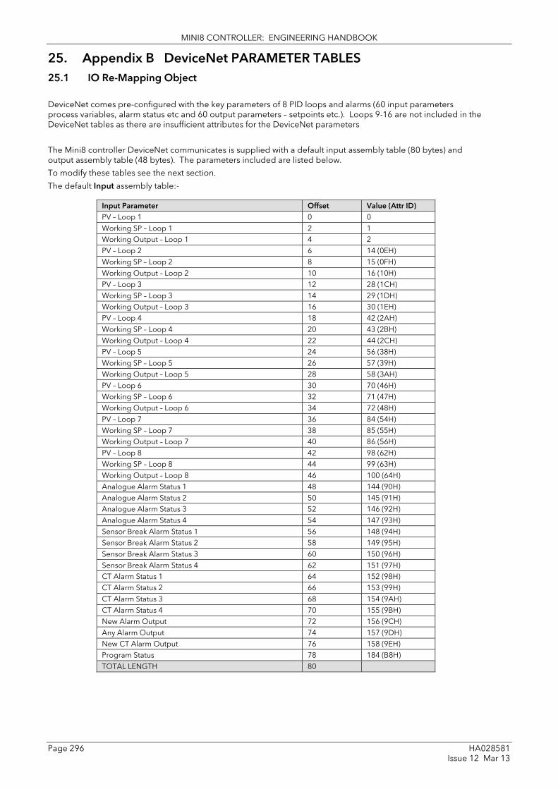
MINI8 CONTROLLER: ENGINEERING HANDBOOK
Page 296 HA028581 Issue 12 Mar 13
25. Appendix B DeviceNet PARAMETER TABLES 25.1 IO Re-Mapping Object
DeviceNet comes pre-configured with the key parameters of 8 PID loops and alarms (60 input parameters process variables, alarm status etc and 60 output parameters – setpoints etc.). Loops 9-16 are not included in the DeviceNet tables as there are insufficient attributes for the DeviceNet parameters
The Mini8 controller DeviceNet communicates is supplied with a default input assembly table (80 bytes) and output assembly table (48 bytes). The parameters included are listed below.
To modify these tables see the next section.
The default Input assembly table:-
Input Parameter Offset Value (Attr ID) PV – Loop 1 0 0 Working SP – Loop 1 2 1 Working Output – Loop 1 4 2 PV – Loop 2 6 14 (0EH) Working SP – Loop 2 8 15 (0FH) Working Output – Loop 2 10 16 (10H) PV – Loop 3 12 28 (1CH) Working SP – Loop 3 14 29 (1DH) Working Output – Loop 3 16 30 (1EH) PV – Loop 4 18 42 (2AH) Working SP – Loop 4 20 43 (2BH) Working Output – Loop 4 22 44 (2CH) PV – Loop 5 24 56 (38H) Working SP – Loop 5 26 57 (39H) Working Output – Loop 5 28 58 (3AH) PV – Loop 6 30 70 (46H) Working SP – Loop 6 32 71 (47H) Working Output – Loop 6 34 72 (48H) PV – Loop 7 36 84 (54H) Working SP – Loop 7 38 85 (55H) Working Output – Loop 7 40 86 (56H) PV – Loop 8 42 98 (62H) Working SP – Loop 8 44 99 (63H) Working Output – Loop 8 46 100 (64H) Analogue Alarm Status 1 48 144 (90H) Analogue Alarm Status 2 50 145 (91H) Analogue Alarm Status 3 52 146 (92H) Analogue Alarm Status 4 54 147 (93H) Sensor Break Alarm Status 1 56 148 (94H) Sensor Break Alarm Status 2 58 149 (95H) Sensor Break Alarm Status 3 60 150 (96H) Sensor Break Alarm Status 4 62 151 (97H) CT Alarm Status 1 64 152 (98H) CT Alarm Status 2 66 153 (99H) CT Alarm Status 3 68 154 (9AH) CT Alarm Status 4 70 155 (9BH) New Alarm Output 72 156 (9CH) Any Alarm Output 74 157 (9DH) New CT Alarm Output 76 158 (9EH) Program Status 78 184 (B8H) TOTAL LENGTH 80

MINI8 CONTROLLER: ENGINEERING HANDBOOK
HA028581 Page 297 Issue 12 Mar 13
The default output assembly table.
Output Parameter Offset Value Target SP – Loop 1 0 3 Auto/Manual – Loop 1 2 7 Manual Output – Loop 1 4 4 Target SP – Loop 2 6 17 (11H) Auto/Manual – Loop 2 8 21 (15H) Manual Output – Loop 2 10 18 (12H) Target SP – Loop 3 12 31 (1FH) Auto/Manual – Loop 3 14 35 (23H) Manual Output – Loop 3 16 32 (20H) Target SP – Loop 4 18 45 (2DH) Auto/Manual – Loop 4 20 49 (31H) Manual Output – Loop 4 22 46 (2EH) Target SP – Loop 5 24 59 (3BH) Auto/Manual – Loop 5 26 63 (3FH) Manual Output – Loop 5 28 60 (3CH) Target SP – Loop 6 30 73 (49H) Auto/Manual – Loop 6 32 77 (4DH) Manual Output – Loop 6 34 74 (4AH) Target SP – Loop 7 36 87 (57H) Auto/Manual – Loop 7 38 91 (5BH) Manual Output – Loop 7 40 88 (58H) Target SP – Loop 8 42 101 (65H) Auto/Manual – Loop 8 44 105 (69H) Manual Output – Loop 8 46 102 (66H) TOTAL LENGTH 48
25.2 Application Variables Object This is the list of parameters available to be included in the input and output tables.
Parameter Attribute ID Process Variable – Loop 1 0 Working Setpoint – Loop 1 1 Working Output – Loop 1 2 Target Setpoint – Loop 1 3 Manual Output – Loop 1 4 Setpoint 1 – Loop 1 5 Setpoint 2 – Loop 1 6 Auto/Manual Mode – Loop 1 7 Proportional Band – Loop 1 working Set 8 Integral Time – Loop 1 working Set 9 Derivative Time – Loop 1 working Set 10 Cutback Low – Loop 1 working Set 11 Cutback High – Loop 1 working Set 12 Relative Cooling Gain – Loop 1 working Set 13 Process Variable – Loop 2 14 Working Setpoint – Loop 2 15 Working Output – Loop 2 16 Target Setpoint – Loop 2 17 Manual Output – Loop 2 18 Setpoint 1 – Loop 2 19 Setpoint 2 – Loop 2 20 Auto/Manual Mode – Loop 2 21 Proportional Band – Loop 2 working Set 22 Integral Time – Loop 2 working Set 23 Derivative Time – Loop 2 working Set 24 Cutback Low – Loop 2 working Set 25 Cutback High – Loop 2 working Set 26 Relative Cooling Gain – Loop 2 working Set 27

MINI8 CONTROLLER: ENGINEERING HANDBOOK
Page 298 HA028581 Issue 12 Mar 13
Parameter Attribute ID Process Variable – Loop 3 28 Working Setpoint – Loop 3 29 Working Output – Loop 3 30 Target Setpoint – Loop 3 31 Manual Output – Loop 3 32 Setpoint 1 – Loop 3 33 Setpoint 2 – Loop 3 34 Auto/Manual Mode – Loop 3 35 Proportional Band – Loop 3 working Set 36 Integral Time – Loop 3 working Set 37 Derivative Time – Loop 3 working Set 38 Cutback Low – Loop 3 working Set 39 Cutback High – Loop 3 working Set 40 Relative Cooling Gain – Loop 3 working Set 41 Process Variable – Loop 4 42 Working Setpoint – Loop 4 43 Working Output – Loop 4 44 Target Setpoint – Loop 4 45 Manual Output – Loop 4 46 Setpoint 1 – Loop 4 47 Setpoint 2 – Loop 4 48 Auto/Manual Mode – Loop 4 49 Proportional Band – Loop 4 working Set 50 Integral Time – Loop 4 working Set 51 Derivative Time – Loop 4 working Set 52 Cutback Low – Loop 4 working Set 53 Cutback High – Loop 4 working Set 54 Relative Cooling Gain – Loop 4 working Set 55 Process Variable – Loop 5 56 Working Setpoint – Loop 5 57 Working Output – Loop 5 58 Target Setpoint – Loop 5 59 Manual Output – Loop 5 60 Setpoint 1 – Loop 5 61 Setpoint 2 – Loop 5 62 Auto/Manual Mode – Loop 5 63 Proportional Band – Loop 5 working Set 64 Integral Time – Loop 5 working Set 65 Derivative Time – Loop 5 working Set 66 Cutback Low – Loop 5 working Set 67 Cutback High – Loop 5 working Set 68 Relative Cooling Gain – Loop 5 working Set 69 Process Variable – Loop 6 70 Working Setpoint – Loop 6 71 Working Output – Loop 6 72 Target Setpoint – Loop 6 73 Manual Output – Loop 6 74 Setpoint 1 – Loop 6 75 Setpoint 2 – Loop 6 76 Auto/Manual Mode – Loop 6 77 Proportional Band – Loop 6 working Set 78 Integral Time – Loop 6 working Set 79 Derivative Time – Loop 6 working Set 80 Cutback Low – Loop 6 working Set 81 Cutback High – Loop 6 working Set 82 Relative Cooling Gain – Loop 6 working Set 83 Process Variable – Loop 7 84 Working Setpoint – Loop 7 85 Working Output – Loop 7 86 Target Setpoint – Loop 7 87

MINI8 CONTROLLER: ENGINEERING HANDBOOK
HA028581 Page 299 Issue 12 Mar 13
Parameter Attribute ID Manual Output – Loop 7 88 Setpoint 1 – Loop 7 89 Setpoint 2 – Loop 7 90 Auto/Manual Mode – Loop 7 91 Proportional Band – Loop 7 working Set 92 Integral Time – Loop 7 working Set 93 Derivative Time – Loop 7 working Set 94 Cutback Low – Loop 7 working Set 95 Cutback High – Loop 7 working Set 96 Relative Cooling Gain – Loop 7 working Set 97 Process Variable – Loop 8 98 Working Setpoint – Loop 8 99 Working Output – Loop 8 100 Target Setpoint – Loop 8 101 Manual Output – Loop 8 102 Setpoint 1 – Loop 8 103 Setpoint 2 – Loop 8 104 Auto/Manual Mode – Loop 8 105 Proportional Band – Loop 8 working Set 106 Integral Time – Loop 8 working Set 107 Derivative Time – Loop 8 working Set 108 Cutback Low – Loop 8 working Set 109 Cutback High – Loop 8 working Set 110 Relative Cooling Gain – Loop 8 working Set 111 Module PV – Channel 1 112 Module PV – Channel 2 113 Module PV – Channel 3 114 Module PV – Channel 4 115 Module PV – Channel 5 116 Module PV – Channel 6 117 Module PV – Channel 7 118 Module PV – Channel 8 119 Module PV – Channel 9 120 Module PV – Channel 10 121 Module PV – Channel 11 122 Module PV – Channel 12 123 Module PV – Channel 13 124 Module PV – Channel 14 125 Module PV – Channel 15 126 Module PV – Channel 16 127 Module PV – Channel 17 128 Module PV – Channel 18 129 Module PV – Channel 19 130 Module PV – Channel 20 131 Module PV – Channel 21 132 Module PV – Channel 22 133 Module PV – Channel 23 134 Module PV – Channel 24 135 Module PV – Channel 25 136 Module PV – Channel 26 137 Module PV – Channel 27 138 Module PV – Channel 28 139 Module PV – Channel 29 140 Module PV – Channel 30 141 Module PV – Channel 31 142 Module PV – Channel 32 143 Analogue Alarm Status 1 144 Analogue Alarm Status 2 145 Analogue Alarm Status 3 146

MINI8 CONTROLLER: ENGINEERING HANDBOOK
Page 300 HA028581 Issue 12 Mar 13
Parameter Attribute ID Analogue Alarm Status 4 147 Sensor Break Alarm Status 1 148 Sensor Break Alarm Status 2 149 Sensor Break Alarm Status 3 150 Sensor Break Alarm Status 4 151 CT Alarm Status 1 152 CT Alarm Status 2 153 CT Alarm Status 3 154 CT Alarm Status 4 155 New Alarm Output 156 Any Alarm Output 157 New CT Alarm Output 158 Reset New Alarm 159 Reset New CT Alarm 160 CT Load Current 1 161 CT Load Current 2 162 CT Load Current 3 163 CT Load Current 4 164 CT Load Current 5 165 CT Load Current 6 166 CT Load Current 7 167 CT Load Current 8 168 CT Load Status 1 169 CT Load Status 2 170 CT Load Status 3 171 CT Load Status 4 172 CT Load Status 5 173 CT Load Status 6 174 CT Load Status 7 175 CT Load Status 8 176 PSU Relay 1 Output 177 PSU Relay 2 Output 178 PSU Digital Input 1 179 PSU Digital Input 2 180 Program Run 181 Program Hold 182 Program Reset 183 Program Status 184 Current Program 185 Program Time Left 186 Segment Time Left 187 User Value 1 188 User Value 2 189 User Value 3 190 User Value 4 191 User Value 5 192 User Value 6 193 User Value 7 194 User Value 8 195 User Value 9 196 User Value 10 197 User Value 11 198 User Value 12 199

MINI8 CONTROLLER: ENGINEERING HANDBOOK
HA028581 Page 301 Issue 12 Mar 13
25.2.1 Table Modification Make a list of parameters required in the input and output tables to suit the application. If the parameter is listed in the predefined list then use the attribute number of that parameter.
USER OUTPUT assembly table
(Max 60)
List of available parameters
Predefined #0 to #199
USER INPUT assembly table
(Max 60)
Mini8 controller Application Variable Object
Mini8 controller IO Remapping Object
To set up the controller so that the required parameters are available on the network requires setting up the INPUT and OUTPUT data assembly tables with the IDs from the Application Variable Object.

MINI8 CONTROLLER: ENGINEERING HANDBOOK
Page 302 HA028581 Issue 12 Mar 13
26. Appendix C CANOPEN PARAMETER TABLES
26.1 Manufacturer Object – Pick List
Object Index 2000h
Sub Index Parameter Data Type
SCADA Address
Receive PDO1 Note: Sub indices 02h – 04h are letter boxed via sub index 01h. 01h Loop Number (Comms.InstNum1) Integer16 15816 02h Loop.n.Main.TargetSP Integer16 15817 03h Loop.n.Main.AutoMan Integer16 15818 04h Loop.n.OP.ManualOutVal Integer16 15819 Receive PDO2 Note: Sub indices 06h – 08h are letter boxed via sub index 05h. 05h Loop Number (Comms.InstNum2) Integer16 15820 06h Loop.n.PID.ProportionalBand Integer16 15821 07h Loop.n.PID.IntegralTime Integer16 15822 08h Loop.n.PID.DerivativeTime Integer16 15823 Receive PDO3 Note: Sub indices 0Ah – 0Ch are letter boxed via sub index 09h. 09h Loop Number (Comms.InstNum3) Integer16 15824 0Ah Loop.n.SP.SP1 Integer16 15825 0Bh Loop.n.SP.SP2 Integer16 15826 0Ch Loop.n.SP.SPSelect Integer16 15827 Receive PDO Note: Sub indices 0Eh – 10h are letter boxed via sub index 0Dh. 0Dh Programmer Number (Comms.InstNum4) Integer16 15828 0Eh Programmer.n.SetUp.ProgRun Integer16 15829 0Fh Programmer.n.SetUp.ProgHold Integer16 15830 10h Programmer.n.SetUp.ProgReset Integer16 15831 Tramsmit PDO1 11h AlmSummary.General.AnAlarmStatus1 Integer16 15832 12h AlmSummary.General.AnAlarmStatus2 Integer16 15833 13h AlmSummary.General.AnAlarmStatus3 Integer16 15834 14h AlmSummary.General.AnAlarmStatus4 Integer16 15835 Transmit PD02 15h AlmSummary.General.SbrkAlarmStatus1 Integer16 15836 16h AlmSummary.General.SbrkAlarmStatus2 Integer16 15837 17h AlmSummary.General.SbrkAlarmStatus3 Integer16 15838 18h AlmSummary.General.SbrkAlarmStatus4 Integer16 15839 Transmit PDO3 Note: Sub indices 1Ah – 1Ch are letter boxed via sub index 19h. 19h Loop Number (Comms.InstNum5) Integer16 15840 1Ah Loop.n.Main.PV Integer16 15841 1Bh Loop.n.Main.WorkingSP Integer16 15842 1Ch Loop.n.Main.ActiveOut Integer16 15843 Transmit PDO4 Note: Sub indices 1Eh – 20h are letter boxed via sub index 1Dh. 1Dh Programmer Number (Comms.InstNum6) Integer16 15844 1Eh Programmer.n.Run.CurProg Integer16 15845 1Fh Programmer.n.Run.ProgStatus Integer16 15846 20h Programmer.n.Run.ProgTimeLeft Integer16 15847 21h Loop.1.Main.PV Integer16 15848 22h Loop.2.Main.PV Integer16 15849 23h Loop.3.Main.PV Integer16 15850 24h Loop.4.Main.PV Integer16 15851 25h Loop.5.Main.PV Integer16 15852 26h Loop.6.Main.PV Integer16 15853 27h Loop.7.Main.PV Integer16 15854 28h Loop.8.Main.PV Integer16 15855 29h Loop.9.Main.PV Integer16 15856 2Ah Loop.10.Main.PV Integer16 15857 2Bh Loop.11.Main.PV Integer16 15858 2Ch Loop.12.Main.PV Integer16 15859 2Dh Loop.13.Main.PV Integer16 15860

MINI8 CONTROLLER: ENGINEERING HANDBOOK
HA028581 Page 303 Issue 12 Mar 13
Object Index 2000h
Sub Index
Parameter Data Type SCADA Address
2Eh Loop.14.Main.PV Integer16 15861 2Fh Loop.15.Main.PV Integer16 15862 30h Loop.16.Main.PV Integer16 15863 31h Loop.1.Main.WorkingSP Integer16 15864 32h Loop.2.Main.WorkingSP Integer16 15865 33h Loop.3.Main.WorkingSP Integer16 15866 34h Loop.4.Main.WorkingSP Integer16 15867 35h Loop.5.Main.WorkingSP Integer16 15868 36h Loop.6.Main.WorkingSP Integer16 15869 37h Loop.7.Main.WorkingSP Integer16 15870 38h Loop.8.Main.WorkingSP Integer16 15871 39h Loop.9.Main.WorkingSP Integer16 15872 3Ah Loop.10.Main.WorkingSP Integer16 15873 3Bh Loop.11.Main.WorkingSP Integer16 15874 3Ch Loop.12.Main.WorkingSP Integer16 15875 3Dh Loop.13.Main.WorkingSP Integer16 15876 3Eh Loop.14.Main.WorkingSP Integer16 15877 3Fh Loop.15.Main.WorkingSP Integer16 15878 40h Loop.16.Main.WorkingSP Integer16 15879 41h Loop.1.Main.ActiveOut Integer16 15880 42h Loop.2.Main.ActiveOut Integer16 15881 43h Loop.3.Main.ActiveOut Integer16 15882 44h Loop.4.Main.ActiveOut Integer16 15883 45h Loop.5.Main.ActiveOut Integer16 15884 46h Loop.6.Main.ActiveOut Integer16 15885 47h Loop.7.Main.ActiveOut Integer16 15886 48h Loop.8.Main.ActiveOut Integer16 15887 49h Loop.9.Main.ActiveOut Integer16 15888 4Ah Loop.10.Main.ActiveOut Integer16 15889 4Bh Loop.11.Main.ActiveOut Integer16 15890 4Ch Loop.12.Main.ActiveOut Integer16 15891 4Dh Loop.13.Main.ActiveOut Integer16 15892 4Eh Loop.14.Main.ActiveOut Integer16 15893 4Fh Loop.15.Main.ActiveOut Integer16 15894 50h Loop.16.Main.ActiveOut Integer16 15895 51h Loop.1.Main.TargetSP Integer16 15896 52h Loop.2.Main.TargetSP Integer16 15897 53h Loop.3.Main.TargetSP Integer16 15898 54h Loop.4.Main.TargetSP Integer16 15899 55h Loop.5.Main.TargetSP Integer16 15900 56h Loop.6.Main.TargetSP Integer16 15901 57h Loop.7.Main.TargetSP Integer16 15902 58h Loop.8.Main.TargetSP Integer16 15903 59h Loop.9.Main.TargetSP Integer16 15904 5Ah Loop.10.Main.TargetSP Integer16 15905 5Bh Loop.11.Main.TargetSP Integer16 15906 5Ch Loop.12.Main.TargetSP Integer16 15907 5Dh Loop.13.Main.TargetSP Integer16 15908 5Eh Loop.14.Main.TargetSP Integer16 15909 5Fh Loop.15.Main.TargetSP Integer16 15910 60h Loop.16.Main.TargetSP Integer16 15911 61h Loop.1.OP.ManualOutVal Integer16 15912 62h Loop.2.OP.ManualOutVal Integer16 15913 63h Loop.3.OP.ManualOutVal Integer16 15914 64h Loop.4.OP.ManualOutVal Integer16 15915 65h Loop.5.OP.ManualOutVal Integer16 15916 66h Loop.6.OP.ManualOutVal Integer16 15917

MINI8 CONTROLLER: ENGINEERING HANDBOOK
Page 304 HA028581 Issue 12 Mar 13
Object Index 2000h
Sub Index
Parameter Data Type SCADA Address
67h Loop.7.OP.ManualOutVal Integer16 15918 68h Loop.8.OP.ManualOutVal Integer16 15919 69h Loop.9.OP.ManualOutVal Integer16 15920 6Ah Loop.10.OP.ManualOutVal Integer16 15921 6Bh Loop.11.OP.ManualOutVal Integer16 15922 6Ch Loop.12.OP.ManualOutVal Integer16 15923 6Dh Loop.13.OP.ManualOutVal Integer16 15924 6Eh Loop.14.OP.ManualOutVal Integer16 15925 6Fh Loop.15.OP.ManualOutVal Integer16 15926 70h Loop.16.OP.ManualOutVal Integer16 15927 71h Loop.1.Main.AutoMan Integer16 15928 72h Loop.2.Main.AutoMan Integer16 15929 73h Loop.3.Main.AutoMan Integer16 15930 74h Loop.4.Main.AutoMan Integer16 15931 75h Loop.5.Main.AutoMan Integer16 15932 76h Loop.6.Main.AutoMan Integer16 15933 77h Loop.7.Main.AutoMan Integer16 15934 78h Loop.8.Main.AutoMan Integer16 15935 79h Loop.9.Main.AutoMan Integer16 15936 7Ah Loop.10.Main.AutoMan Integer16 15937 7Bh Loop.11.Main.AutoMan Integer16 15938 7Ch Loop.12.Main.AutoMan Integer16 15939 7Dh Loop.13.Main.AutoMan Integer16 15940 7Eh Loop.14.Main.AutoMan Integer16 15941 7Fh Loop.15.Main.AutoMan Integer16 15942 80h Loop.16.Main.AutoMan Integer16 15943 81h IO.Mod.1.PV Integer16 15944 82h IO.Mod.2.PV Integer16 15945 83h IO.Mod.3.PV Integer16 15946 84h IO.Mod.4.PV Integer16 15947 85h IO.Mod.5.PV Integer16 15948 86h IO.Mod.6.PV Integer16 15949 87h IO.Mod.7.PV Integer16 15950 88h IO.Mod.8.PV Integer16 15951 89h IO.Mod.9.PV Integer16 15952 8Ah IO.Mod.10.PV Integer16 15953 8Bh IO.Mod.11.PV Integer16 15954 8Ch IO.Mod.12.PV Integer16 15955 8Dh IO.Mod.13.PV Integer16 15956 8Eh IO.Mod.14.PV Integer16 15957 8Fh IO.Mod.15.PV Integer16 15958 90h IO.Mod.16.PV Integer16 15959 91h IO.Mod.17.PV Integer16 15960 92h IO.Mod.18.PV Integer16 15961 93h IO.Mod.19.PV Integer16 15962 94h IO.Mod.20.PV Integer16 15963 95h IO.Mod.21.PV Integer16 15964 96h IO.Mod.22.PV Integer16 15965 97h IO.Mod.23.PV Integer16 15966 98h IO.Mod.24.PV Integer16 15967 99h IO.Mod.25.PV Integer16 15968 9Ah IO.Mod.26.PV Integer16 15969 9Bh IO.Mod.27.PV Integer16 15970 9Ch IO.Mod.28.PV Integer16 15971 9Dh IO.Mod.29.PV Integer16 15972 9Eh IO.Mod.30.PV Integer16 15973 9Fh IO.Mod.31.PV Integer16 15974 A0h IO.Mod.32.PV Integer16 15975

MINI8 CONTROLLER: ENGINEERING HANDBOOK
HA028581 Page 305 Issue 12 Mar 13
Object Index 2000h
Sub Index
Parameter Data Type SCADA Address
A1h IO.FixedIO.A.PV Integer16 15976 A2h IO.FixedIO.B.PV Integer16 15977 A3h IO.FixedIO.D1.PV Integer16 15978 A4h IO.FixedIO.D2.PV Integer16 15979 A5h IO.CurrentMonitor.Status.Load1Current Integer16 15980 A6h IO.CurrentMonitor.Status.Load2Current Integer16 15981 A7h IO.CurrentMonitor.Status.Load3Current Integer16 15982 A8h IO.CurrentMonitor.Status.Load4Current Integer16 15983 A9h IO.CurrentMonitor.Status.Load5Current Integer16 15984 AAh IO.CurrentMonitor.Status.Load6Current Integer16 15985 ABh IO.CurrentMonitor.Status.Load7Current Integer16 15986 ACh IO.CurrentMonitor.Status.Load8Current Integer16 15987 ADh IO.CurrentMonitor.Status.Load1Status Integer16 15988 AEh IO.CurrentMonitor.Status.Load2Status Integer16 15989 AFh IO.CurrentMonitor.Status.Load3Status Integer16 15990 B0h IO.CurrentMonitor.Status.Load4Status Integer16 15991 B1h IO.CurrentMonitor.Status.Load5Status Integer16 15992 B2h IO.CurrentMonitor.Status.Load6Status Integer16 15993 B3h IO.CurrentMonitor.Status.Load7Status Integer16 15994 B4h IO.CurrentMonitor.Status.Load8Status Integer16 15995 B5h AlmSummary.General.AnyAlarm Integer16 15996 B6h AlmSummary.General.NewAlarm Integer16 15997 B7h AlmSummary.General.NewCTAlarm Integer16 15998 B8h AlmSummary.General.RstNewAlarm Integer16 15999 B9h AlmSummary.General.RstNewCTAlarm Integer16 16000 BAh AlmSummary.General.CTAlarmStatus1 Integer16 16001 BBh AlmSummary.General.CTAlarmStatus2 Integer16 16002 BCh AlmSummary.General.CTAlarmStatus3 Integer16 16003 BDh AlmSummary.General.CTAlarmStatus4 Integer16 16004 BEh AlmSummary.General.DigAlarmStatus1 Integer16 16005 BFh AlmSummary.General.DigAlarmStatus2 Integer16 16006 C0h AlmSummary.General.DigAlarmStatus3 Integer16 16007 C1h AlmSummary.General.DigAlarmStatus4 Integer16 16008 C2h AlmSummary.General.GlobalAck Integer16 16009 C3h UserVal.1.Val Integer16 16010 C4h UserVal.2.Val Integer16 16011 C5h UserVal.3.Val Integer16 16012 C6h UserVal.4.Val Integer16 16013 C7h UserVal.5.Val Integer16 16014 C8h UserVal.6.Val Integer16 16015

MINI8 CONTROLLER: ENGINEERING HANDBOOK
Page 306 HA028581 Issue 12 Mar 13
27. Appendix D Version 1.xx Programmer 27.1 Version 1.xx Parameter Tables 27.1.1 Configuring the Programmer (V1.xx)
Programmer.1.Setup contains the general configuration settings for the Programmer Block. Programs are created and stored in the Program Folder. Once a Program exists it can be run using the parameters in the Programmer.1.Run folder.
Folder – Programmer.1 Sub-folder: Setup
Name Parameter Description Value Default Access Level
Units Units of the Output None Conf
Resolution Programmer Output resolution X to X.XXXX Conf
PVIn The programmer uses the PV input for a number of functions In holdback, the PV is monitored against the setpoint, and if a deviation occurs the program is paused. The programmer can be configured to start its profile from the current PV value (servo to PV). The programmer monitors the PV value for Sensor Break. The programmer holds in sensor break.
The PV Input is normally wired from the loop TrackPV parameter. Note: This input is automatically wired when the programmer and loop are enabled and there are no existing wires to track interface parameters. Track interface parameters are Programmer.Setup, PVInput, SPInput, Loop.SP, AltSP, Loop.SP, AltSPSelect.
Conf
SPIn The programmer needs to know the working setpoint of the loop it is profiling. The SP input is used in the servo to setpoint start type.
SP Input is normally wired from the loop Track SP parameter as the PV input.
Conf
Servo The transfer of program setpoint to PV Input (normally the Loop PV) or the SP Input (normally the Loop setpoint).
PV SP
See also section 18.7.1
Conf
PowerFailAct Power fail recovery strategy Ramp See section 18.8. Conf
Reset
Cont
SyncIn The synchronise input is a way of synchronising programs. At the end of a segment the programmer will inspect the sync. input, if it is True (1) then the programmer will advance to the next segment. It is typically wired from the end of segment output of another programmer. Only appears if ‘SyncMode’ = ‘Yes’
0 1
This will normally be wired to the ‘End of Seg’ parameter.
Oper
Max Events To set the maximum number of output events required for the program. This is for convenience to avoid having to scroll through unwanted events when setting up each segment
1 to 8 Conf
SyncMode Allows multiple controllers to be synchronised at the end of each segment
No Sync output disabled Conf
Yes Sync output enabled
Prog Reset Flag showing reset state No/Yes Can be wired to logic inputs to provide remote program control
Oper
Prog Run Flag showing run state No/Yes Oper
Prog Hold Flag showing hold state No/Yes Oper
AdvSeg Set output to target setpoint and advance to next segment
No/Yes Oper
SkipSeg Skip to the next setpoint and start the segment at the current output value.
No/Yes Oper
EventOut1 to 8 Flags showing event states No/Yes R/O
End of Seg Flag showing end of segment state No/Yes R/O

MINI8 CONTROLLER: ENGINEERING HANDBOOK
HA028581 Page 307 Issue 12 Mar 13
27.1.2 To Select, Run, Hold or Reset a Program (V1.xx). The ‘Run’ folder allows an existing program to be selected and run. The folder also shows the current program status:
Folder – Programmer.1 Sub-folder: Run
Name
Parameter Description Value
Default Access Level
CurProg Current Program Number 0 to 50. Change only when Programmer is in Reset.
0 Oper R/O
CurrSeg Current Running Segment 1 to 255 1 R/O
ProgStatus Program Status Reset – Run – Hold – Holdback – End –
Oper
PSP Programmer Setpoint 0 R/O
CyclesLeft Number of Cycles Remaining 0 to 1000 0 R/O
CurSegType Current Segment type End Rate Time Dwell Step Call
End R/O
SegTimeLeft Segment Time Remaining Hr Min Sec Millisec 0 R/O
ResetEventOP Reset Event Outputs 0 to 255, each bit resets its corresponding output
0 Oper
SegTarget Current Target Setpoint Value R/O
SegRate Segment Ramp Rate 0.1 to 9999.9 0 R/O
ProgTimeLeft Program Time Remaining Hrs Min Sec Millisec 0 R/O
FastRun Fast Run No (0) Normal Yes (1) Program executes at 10 times real time
No Conf
EndOutput End Output Off (0) Program not in End On (1) Program at End
Off R/O
EventsOut Event Outputs 0 to 255, each bit represents an output.
0 R/O
27.1.3 Creating a Program (V1.xx) A folder exists for each Program containing a few key parameters listed below. This folder would normally be viewed via the iTools Program Editor under the Program Parameters tab. The Program Editor is used to create the segments of Program itself using the Segment Editor tab.
Folder – Program Sub-folder: 1 to 50
Name Parameter Description Value Default Access Level
Name Program Name Up to 8 characters Null Oper
Holdback Value
Deviation between SP and PV at which holdback is applied. This value applies to the whole program.
Minimum setting 0 0 Oper
Ramp Units Time units applied to the segments Sec Min Hour
Seconds Minutes Hours
sec Oper
Cycles Number of times the whole program repeats Cont (0) 1 to 999
Repeats continuously Program executes once to 999 times
1 Oper
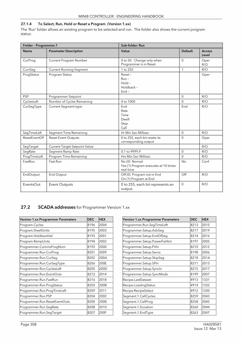
MINI8 CONTROLLER: ENGINEERING HANDBOOK
Page 308 HA028581 Issue 12 Mar 13
27.1.4 To Select, Run, Hold or Reset a Program (Version 1.xx) The ‘Run’ folder allows an existing program to be selected and run. The folder also shows the current program status:
Folder – Programmer.1 Sub-folder: Run
Name
Parameter Description Value
Default Access Level
CurProg Current Program Number 0 to 50. Change only when Programmer is in Reset.
0 Oper R/O
CurrSeg Current Running Segment 1 to 255 1 R/O
ProgStatus Program Status Reset – Run – Hold – Holdback – End –
Oper
PSP Programmer Setpoint 0 R/O
CyclesLeft Number of Cycles Remaining 0 to 1000 0 R/O
CurSegType Current Segment type End Rate Time Dwell Step Call
End R/O
SegTimeLeft Segment Time Remaining Hr Min Sec Millisec 0 R/O
ResetEventOP Reset Event Outputs 0 to 255, each bit resets its corresponding output
0 Oper
SegTarget Current Target Setpoint Value R/O
SegRate Segment Ramp Rate 0.1 to 9999.9 0 R/O
ProgTimeLeft Program Time Remaining Hrs Min Sec Millisec 0 R/O
FastRun Fast Run No (0) Normal Yes (1) Program executes at 10 times real time
No Conf
EndOutput End Output Off (0) Program not in End On (1) Program at End
Off R/O
EventsOut Event Outputs 0 to 255, each bit represents an output.
0 R/O
27.2 SCADA addresses for Programmer Version 1.xx
Version 1.xx Programmer Parameters DEC HEX
Program.Cycles 8196 2004
Program.DwellUnits 8195 2003
Program.HoldbackVal 8193 2001
Program.RampUnits 8194 2002
Programmer.CommsProgNum 8192 2000
Programmer.Run.CurProg 8201 2009
Programmer.Run.CurSeg 8202 200A
Programmer.Run.CurSegType 8206 200E
Programmer.Run.CyclesLeft 8205 200D
Programmer.Run.EventOuts 8212 2014
Programmer.Run.FastRun 8216 2018
Programmer.Run.ProgStatus 8203 200B
Programmer.Run.ProgTimeLeft 8209 2011
Programmer.Run.PSP 8204 200C
Programmer.Run.ResetEventOuts 8200 2008
Programmer.Run.SegRate 8208 2010
Programmer.Run.SegTarget 8207 200F
Version 1.xx Programmer Parameters DEC HEX
Programmer.Run.SegTimeLeft 8213 2015
Programmer.Setup.AdvSeg 8217 2019
Programmer.Setup.EndOfSeg 8214 2016
Programmer.Setup.PowerFailAct 8197 2005
Programmer.Setup.PVIn 8210 2012
Programmer.Setup.Servo 8198 2006
Programmer.Setup.SkipSeg 8218 201A
Programmer.Setup.SPIn 8211 2013
Programmer.Setup.SyncIn 8215 2017
Programmer.Setup.SyncMode 8199 2007
Recipe.LastDataset 4913 1331
Recipe.LoadingStatus 4914 1332
Recipe.RecipeSelect 4912 1330
Segment.1.CallCycles 8259 2043
Segment.1.CallProg 8258 2042
Segment.1.Duration 8260 2044
Segment.1.EndType 8263 2047

MINI8 CONTROLLER: ENGINEERING HANDBOOK
HA028581 Page 309 Issue 12 Mar 13
Version 1.xx Programmer Parameters DEC HEX
Segment.1.EventOuts 8264 2048
Segment.1.Holdback 8257 2041
Segment.1.RampRate 8261 2045
Segment.1.SegType 8256 2040
Segment.1.TargetSP 8262 2046
Segment.2.CallCycles 8275 2053
Segment.2.CallProg 8274 2052
Segment.2.Duration 8276 2054
Segment.2.EndType 8279 2057
Segment.2.EventOuts 8280 2058
Segment.2.Holdback 8273 2051
Segment.2.RampRate 8277 2055
Segment.2.SegType 8272 2050
Segment.2.TargetSP 8278 2056
Segment.3.CallCycles 8291 2063
Segment.3.CallProg 8290 2062
Segment.3.Duration 8292 2064
Segment.3.EndType 8295 2067
Segment.3.EventOuts 8296 2068
Segment.3.Holdback 8289 2061
Segment.3.RampRate 8293 2065
Segment.3.SegType 8288 2060
Segment.3.TargetSP 8294 2066
Segment.4.CallCycles 8307 2073
Segment.4.CallProg 8306 2072
Segment.4.Duration 8308 2074
Segment.4.EndType 8311 2077
Segment.4.EventOuts 8312 2078
Segment.4.Holdback 8305 2071
Segment.4.RampRate 8309 2075
Segment.4.SegType 8304 2070
Segment.4.TargetSP 8310 2076
Segment.5.CallCycles 8323 2083
Segment.5.CallProg 8322 2082
Segment.5.Duration 8324 2084
Segment.5.EndType 8327 2087
Segment.5.EventOuts 8328 2088
Segment.5.Holdback 8321 2081
Segment.5.RampRate 8325 2085
Segment.5.SegType 8320 2080
Segment.5.TargetSP 8326 2086
Segment.6.CallCycles 8339 2093
Segment.6.CallProg 8338 2092
Segment.6.Duration 8340 2094
Segment.6.EndType 8343 2097
Segment.6.EventOuts 8344 2098
Segment.6.Holdback 8337 2091
Segment.6.RampRate 8341 2095
Segment.6.SegType 8336 2090
Segment.6.TargetSP 8342 2096
Segment.7.CallCycles 8355 20A3
Segment.7.CallProg 8354 20A2
Segment.7.Duration 8356 20A4
Version 1.xx Programmer Parameters DEC HEX
Segment.7.EndType 8359 20A7
Segment.7.EventOuts 8360 20A8
Segment.7.Holdback 8353 20A1
Segment.7.RampRate 8357 20A5
Segment.7.SegType 8352 20A0
Segment.7.TargetSP 8358 20A6
Segment.8.CallCycles 8371 20B3
Segment.8.CallProg 8370 20B2
Segment.8.Duration 8372 20B4
Segment.8.EndType 8375 20B7
Segment.8.EventOuts 8376 20B8
Segment.8.Holdback 8369 20B1
Segment.8.RampRate 8373 20B5
Segment.8.SegType 8368 20B0
Segment.8.TargetSP 8374 20B6
Segment.9.CallCycles 8387 20C3
Segment.9.CallProg 8386 20C2
Segment.9.Duration 8388 20C4
Segment.9.EndType 8391 20C7
Segment.9.EventOuts 8392 20C8
Segment.9.Holdback 8385 20C1
Segment.9.RampRate 8389 20C5
Segment.9.SegType 8384 20C0
Segment.9.TargetSP 8390 20C6
Segment.10.CallCycles 8403 20D3
Segment.10.CallProg 8402 20D2
Segment.10.Duration 8404 20D4
Segment.10.EndType 8407 20D7
Segment.10.EventOuts 8408 20D8
Segment.10.Holdback 8401 20D1
Segment.10.RampRate 8405 20D5
Segment.10.SegType 8400 20D0
Segment.10.TargetSP 8406 20D6
Segment.11.CallCycles 8419 20E3
Segment.11.CallProg 8418 20E2
Segment.11.Duration 8420 20E4
Segment.11.EndType 8423 20E7
Segment.11.EventOuts 8424 20E8
Segment.11.Holdback 8417 20E1
Segment.11.RampRate 8421 20E5
Segment.11.SegType 8416 20E0
Segment.11.TargetSP 8422 20E6
Segment.12.CallCycles 8435 20F3
Segment.12.CallProg 8434 20F2
Segment.12.Duration 8436 20F4
Segment.12.EndType 8439 20F7
Segment.12.EventOuts 8440 20F8
Segment.12.Holdback 8433 20F1
Segment.12.RampRate 8437 20F5
Segment.12.SegType 8432 20F0
Segment.12.TargetSP 8438 20F6
Segment.13.CallCycles 8451 2103
Segment.13.CallProg 8450 2102

MINI8 CONTROLLER: ENGINEERING HANDBOOK
Page 310 HA028581 Issue 12 Mar 13
Version 1.xx Programmer Parameters DEC HEX
Segment.13.Duration 8452 2104
Segment.13.EndType 8455 2107
Segment.13.EventOuts 8456 2108
Segment.13.Holdback 8449 2101
Segment.13.RampRate 8453 2105
Segment.13.SegType 8448 2100
Segment.13.TargetSP 8454 2106
Segment.14.CallCycles 8467 2113
Segment.14.CallProg 8466 2112
Segment.14.Duration 8468 2114
Segment.14.EndType 8471 2117
Segment.14.EventOuts 8472 2118
Segment.14.Holdback 8465 2111
Segment.14.RampRate 8469 2115
Segment.14.SegType 8464 2110
Segment.14.TargetSP 8470 2116
Segment.15.CallCycles 8483 2123
Segment.15.CallProg 8482 2122
Segment.15.Duration 8484 2124
Segment.15.EndType 8487 2127
Segment.15.EventOuts 8488 2128
Segment.15.Holdback 8481 2121
Segment.15.RampRate 8485 2125
Segment.15.SegType 8480 2120
Segment.15.TargetSP 8486 2126
Segment.16.CallCycles 8499 2133
Segment.16.CallProg 8498 2132
Segment.16.Duration 8500 2134
Segment.16.EndType 8503 2137
Segment.16.EventOuts 8504 2138
Segment.16.Holdback 8497 2131
Segment.16.RampRate 8501 2135
Segment.16.SegType 8496 2130
Segment.16.TargetSP 8502 2136
Segment.17.CallCycles 8515 2143
Segment.17.CallProg 8514 2142
Segment.17.Duration 8516 2144
Segment.17.EndType 8519 2147
Segment.17.EventOuts 8520 2148
Segment.17.Holdback 8513 2141
Segment.17.RampRate 8517 2145
Segment.17.SegType 8512 2140
Segment.17.TargetSP 8518 2146
Segment.18.CallCycles 8531 2153
Segment.18.CallProg 8530 2152
Segment.18.Duration 8532 2154
Segment.18.EndType 8535 2157
Segment.18.EventOuts 8536 2158
Segment.18.Holdback 8529 2151
Segment.18.RampRate 8533 2155
Segment.18.SegType 8528 2150
Segment.18.TargetSP 8534 2156
Segment.19.CallCycles 8547 2163
Version 1.xx Programmer Parameters DEC HEX
Segment.19.CallProg 8546 2162
Segment.19.Duration 8548 2164
Segment.19.EndType 8551 2167
Segment.19.EventOuts 8552 2168
Segment.19.Holdback 8545 2161
Segment.19.RampRate 8549 2165
Segment.19.SegType 8544 2160
Segment.19.TargetSP 8550 2166
Segment.20.CallCycles 8563 2173
Segment.20.CallProg 8562 2172
Segment.20.Duration 8564 2174
Segment.20.EndType 8567 2177
Segment.20.EventOuts 8568 2178
Segment.20.Holdback 8561 2171
Segment.20.RampRate 8565 2175
Segment.20.SegType 8560 2170
Segment.20.TargetSP 8566 2176
Segment.21.CallCycles 8579 2183
Segment.21.CallProg 8578 2182
Segment.21.Duration 8580 2184
Segment.21.EndType 8583 2187
Segment.21.EventOuts 8584 2188
Segment.21.Holdback 8577 2181
Segment.21.RampRate 8581 2185
Segment.21.SegType 8576 2180
Segment.21.TargetSP 8582 2186
Segment.22.CallCycles 8595 2193
Segment.22.CallProg 8594 2192
Segment.22.Duration 8596 2194
Segment.22.EndType 8599 2197
Segment.22.EventOuts 8600 2198
Segment.22.Holdback 8593 2191
Segment.22.RampRate 8597 2195
Segment.22.SegType 8592 2190
Segment.22.TargetSP 8598 2196
Segment.23.CallCycles 8611 21A3
Segment.23.CallProg 8610 21A2
Segment.23.Duration 8612 21A4
Segment.23.EndType 8615 21A7
Segment.23.EventOuts 8616 21A8
Segment.23.Holdback 8609 21A1
Segment.23.RampRate 8613 21A5
Segment.23.SegType 8608 21A0
Segment.23.TargetSP 8614 21A6
Segment.24.CallCycles 8627 21B3
Segment.24.CallProg 8626 21B2
Segment.24.Duration 8628 21B4
Segment.24.EndType 8631 21B7
Segment.24.EventOuts 8632 21B8
Segment.24.Holdback 8625 21B1
Segment.24.RampRate 8629 21B5
Segment.24.SegType 8624 21B0
Segment.24.TargetSP 8630 21B6

MINI8 CONTROLLER: ENGINEERING HANDBOOK
HA028581 Page 311 Issue 12 Mar 13
Version 1.xx Programmer Parameters DEC HEX
Segment.25.CallCycles 8643 21C3
Segment.25.CallProg 8642 21C2
Segment.25.Duration 8644 21C4
Segment.25.EndType 8647 21C7
Segment.25.EventOuts 8648 21C8
Segment.25.Holdback 8641 21C1
Segment.25.RampRate 8645 21C5
Segment.25.SegType 8640 21C0
Segment.25.TargetSP 8646 21C6
Segment.26.CallCycles 8659 21D3
Segment.26.CallProg 8658 21D2
Segment.26.Duration 8660 21D4
Segment.26.EndType 8663 21D7
Segment.26.EventOuts 8664 21D8
Segment.26.Holdback 8657 21D1
Segment.26.RampRate 8661 21D5
Segment.26.SegType 8656 21D0
Segment.26.TargetSP 8662 21D6
Segment.27.CallCycles 8675 21E3
Segment.27.CallProg 8674 21E2
Segment.27.Duration 8676 21E4
Segment.27.EndType 8679 21E7
Segment.27.EventOuts 8680 21E8
Segment.27.Holdback 8673 21E1
Segment.27.RampRate 8677 21E5
Segment.27.SegType 8672 21E0
Segment.27.TargetSP 8678 21E6
Segment.28.CallCycles 8691 21F3
Segment.28.CallProg 8690 21F2
Segment.28.Duration 8692 21F4
Segment.28.EndType 8695 21F7
Segment.28.EventOuts 8696 21F8
Segment.28.Holdback 8689 21F1
Segment.28.RampRate 8693 21F5
Segment.28.SegType 8688 21F0
Segment.28.TargetSP 8694 21F6
Segment.29.CallCycles 8707 2203
Segment.29.CallProg 8706 2202
Segment.29.Duration 8708 2204
Segment.29.EndType 8711 2207
Segment.29.EventOuts 8712 2208
Segment.29.Holdback 8705 2201
Segment.29.RampRate 8709 2205
Segment.29.SegType 8704 2200
Segment.29.TargetSP 8710 2206
Segment.30.CallCycles 8723 2213
Segment.30.CallProg 8722 2212
Segment.30.Duration 8724 2214
Segment.30.EndType 8727 2217
Segment.30.EventOuts 8728 2218
Segment.30.Holdback 8721 2211
Segment.30.RampRate 8725 2215
Segment.30.SegType 8720 2210
Version 1.xx Programmer Parameters DEC HEX
Segment.30.TargetSP 8726 2216
Segment.31.CallCycles 8739 2223
Segment.31.CallProg 8738 2222
Segment.31.Duration 8740 2224
Segment.31.EndType 8743 2227
Segment.31.EventOuts 8744 2228
Segment.31.Holdback 8737 2221
Segment.31.RampRate 8741 2225
Segment.31.SegType 8736 2220
Segment.31.TargetSP 8742 2226
Segment.32.CallCycles 8755 2233
Segment.32.CallProg 8754 2232
Segment.32.Duration 8756 2234
Segment.32.EndType 8759 2237
Segment.32.EventOuts 8760 2238
Segment.32.Holdback 8753 2231
Segment.32.RampRate 8757 2235
Segment.32.SegType 8752 2230
Segment.32.TargetSP 8758 2236
Segment.33.CallCycles 8771 2243
Segment.33.CallProg 8770 2242
Segment.33.Duration 8772 2244
Segment.33.EndType 8775 2247
Segment.33.EventOuts 8776 2248
Segment.33.Holdback 8769 2241
Segment.33.RampRate 8773 2245
Segment.33.SegType 8768 2240
Segment.33.TargetSP 8774 2246
Segment.34.CallCycles 8787 2253
Segment.34.CallProg 8786 2252
Segment.34.Duration 8788 2254
Segment.34.EndType 8791 2257
Segment.34.EventOuts 8792 2258
Segment.34.Holdback 8785 2251
Segment.34.RampRate 8789 2255
Segment.34.SegType 8784 2250
Segment.34.TargetSP 8790 2256
Segment.35.CallCycles 8803 2263
Segment.35.CallProg 8802 2262
Segment.35.Duration 8804 2264
Segment.35.EndType 8807 2267
Segment.35.EventOuts 8808 2268
Segment.35.Holdback 8801 2261
Segment.35.RampRate 8805 2265
Segment.35.SegType 8800 2260
Segment.35.TargetSP 8806 2266
Segment.36.CallCycles 8819 2273
Segment.36.CallProg 8818 2272
Segment.36.Duration 8820 2274
Segment.36.EndType 8823 2277
Segment.36.EventOuts 8824 2278
Segment.36.Holdback 8817 2271
Segment.36.RampRate 8821 2275

MINI8 CONTROLLER: ENGINEERING HANDBOOK
Page 312 HA028581 Issue 12 Mar 13
Version 1.xx Programmer Parameters DEC HEX
Segment.36.SegType 8816 2270
Segment.36.TargetSP 8822 2276
Segment.37.CallCycles 8835 2283
Segment.37.CallProg 8834 2282
Segment.37.Duration 8836 2284
Segment.37.EndType 8839 2287
Segment.37.EventOuts 8840 2288
Segment.37.Holdback 8833 2281
Segment.37.RampRate 8837 2285
Segment.37.SegType 8832 2280
Segment.37.TargetSP 8838 2286
Segment.38.CallCycles 8851 2293
Segment.38.CallProg 8850 2292
Segment.38.Duration 8852 2294
Segment.38.EndType 8855 2297
Segment.38.EventOuts 8856 2298
Segment.38.Holdback 8849 2291
Segment.38.RampRate 8853 2295
Segment.38.SegType 8848 2290
Segment.38.TargetSP 8854 2296
Segment.39.CallCycles 8867 22A3
Segment.39.CallProg 8866 22A2
Segment.39.Duration 8868 22A4
Segment.39.EndType 8871 22A7
Segment.39.EventOuts 8872 22A8
Segment.39.Holdback 8865 22A1
Segment.39.RampRate 8869 22A5
Segment.39.SegType 8864 22A0
Segment.39.TargetSP 8870 22A6
Segment.40.CallCycles 8883 22B3
Segment.40.CallProg 8882 22B2
Segment.40.Duration 8884 22B4
Segment.40.EndType 8887 22B7
Segment.40.EventOuts 8888 22B8
Segment.40.Holdback 8881 22B1
Segment.40.RampRate 8885 22B5
Segment.40.SegType 8880 22B0
Segment.40.TargetSP 8886 22B6
Segment.41.CallCycles 8899 22C3
Segment.41.CallProg 8898 22C2
Segment.41.Duration 8900 22C4
Segment.41.EndType 8903 22C7
Segment.41.EventOuts 8904 22C8
Segment.41.Holdback 8897 22C1
Segment.41.RampRate 8901 22C5
Segment.41.SegType 8896 22C0
Segment.41.TargetSP 8902 22C6
Segment.42.CallCycles 8915 22D3
Segment.42.CallProg 8914 22D2
Segment.42.Duration 8916 22D4
Segment.42.EndType 8919 22D7
Segment.42.EventOuts 8920 22D8
Segment.42.Holdback 8913 22D1
Version 1.xx Programmer Parameters DEC HEX
Segment.42.RampRate 8917 22D5
Segment.42.SegType 8912 22D0
Segment.42.TargetSP 8918 22D6
Segment.43.CallCycles 8931 22E3
Segment.43.CallProg 8930 22E2
Segment.43.Duration 8932 22E4
Segment.43.EndType 8935 22E7
Segment.43.EventOuts 8936 22E8
Segment.43.Holdback 8929 22E1
Segment.43.RampRate 8933 22E5
Segment.43.SegType 8928 22E0
Segment.43.TargetSP 8934 22E6
Segment.44.CallCycles 8947 22F3
Segment.44.CallProg 8946 22F2
Segment.44.Duration 8948 22F4
Segment.44.EndType 8951 22F7
Segment.44.EventOuts 8952 22F8
Segment.44.Holdback 8945 22F1
Segment.44.RampRate 8949 22F5
Segment.44.SegType 8944 22F0
Segment.44.TargetSP 8950 22F6
Segment.45.CallCycles 8963 2303
Segment.45.CallProg 8962 2302
Segment.45.Duration 8964 2304
Segment.45.EndType 8967 2307
Segment.45.EventOuts 8968 2308
Segment.45.Holdback 8961 2301
Segment.45.RampRate 8965 2305
Segment.45.SegType 8960 2300
Segment.45.TargetSP 8966 2306
Segment.46.CallCycles 8979 2313
Segment.46.CallProg 8978 2312
Segment.46.Duration 8980 2314
Segment.46.EndType 8983 2317
Segment.46.EventOuts 8984 2318
Segment.46.Holdback 8977 2311
Segment.46.RampRate 8981 2315
Segment.46.SegType 8976 2310
Segment.46.TargetSP 8982 2316
Segment.47.CallCycles 8995 2323
Segment.47.CallProg 8994 2322
Segment.47.Duration 8996 2324
Segment.47.EndType 8999 2327
Segment.47.EventOuts 9000 2328
Segment.47.Holdback 8993 2321
Segment.47.RampRate 8997 2325
Segment.47.SegType 8992 2320
Segment.47.TargetSP 8998 2326
Segment.48.CallCycles 9011 2333
Segment.48.CallProg 9010 2332
Segment.48.Duration 9012 2334
Segment.48.EndType 9015 2337
Segment.48.EventOuts 9016 2338

MINI8 CONTROLLER: ENGINEERING HANDBOOK
HA028581 Page 313 Issue 12 Mar 13
Version 1.xx Programmer Parameters DEC HEX
Segment.48.Holdback 9009 2331
Segment.48.RampRate 9013 2335
Segment.48.SegType 9008 2330
Segment.48.TargetSP 9014 2336
Segment.49.CallCycles 9027 2343
Segment.49.CallProg 9026 2342
Segment.49.Duration 9028 2344
Segment.49.EndType 9031 2347
Segment.49.EventOuts 9032 2348
Segment.49.Holdback 9025 2341
Segment.49.RampRate 9029 2345
Segment.49.SegType 9024 2340
Segment.49.TargetSP 9030 2346
Segment.50.CallCycles 9043 2353
Segment.50.CallProg 9042 2352
Segment.50.Duration 9044 2354
Segment.50.EndType 9047 2357
Segment.50.EventOuts 9048 2358
Segment.50.Holdback 9041 2351
Segment.50.RampRate 9045 2355
Segment.50.SegType 9040 2350
Segment.50.TargetSP 9046 2356

MINI8 CONTROLLER: ENGINEERING HANDBOOK
Page 314 HA028581 Issue 12 Mar 13
28. Appendix E Safety and EMC Information Eurotherm Controls Ltd manufactures this controller in the UK.
Please read this section carefully before installing the controller
This controller is intended for industrial temperature and process control applications where it will meet the requirements of the European Directives on Safety and EMC. If the instrument is used in a manner not specified in this manual, the safety or EMC protection provided by the instrument may be impaired. The installer must ensure the safety and EMC of any particular installation.
The Mini8 controller is intended for operation at safe low voltage levels, except the RL8 relay module. Voltages in excess of 42 volts must not be applied to any terminals other than the RL8 relay module.
Protective Earth Connection is required.
Safety This controller complies with the European Low Voltage Directive 2006/95/EC, by the application of the safety standard EN 61010. The earth stud should be connected to safety earth before other connections are made.
Electromagnetic compatibility This controller conforms with the essential protection requirements of the EMC Directive 2004/108/EC, by the application of EMC standard EN61326
Unpacking and storage The packaging should contain an instrument and an Installation guide. It may contain a CD.
If on receipt, the packaging or the instrument is damaged, do not install the product but contact your supplier.
If the instrument is to be stored before use, protect it from humidity and dust in an ambient temperature range of -10oC to +70oC.
SERVICE AND REPAIR
This controller has no user serviceable parts. Contact your supplier for repair.
Cleaning Do not use water or water based products to clean labels or they will become illegible. Isopropyl alcohol may be used to clean labels. A mild soap solution may be used to clean other exterior surfaces of the product.
GENERAL
The information contained in this manual is subject to change without notice. While every effort has been made to ensure the accuracy of the information, your supplier shall not be held liable for errors contained herein.

MINI8 CONTROLLER: ENGINEERING HANDBOOK
HA028581 Page 315 Issue 12 Mar 13
INSTALLATION SAFETY REQUIREMENTS
Safety Symbols Various symbols are used on the instrument, they have the following meaning:
! Caution (refer to the accompanying documents Protective Conductor Terminal
Personnel Installation must only be carried out by suitably qualified personnel.
Mounting The Mini8 controller should be mounted in a suitable enclosure with suitable ventilation to ensure the ambient temperature remains below 50ºC.
Wiring It is important to connect the controller in accordance with the wiring data given in this guide. Take particular care not to connect AC supplies to the low voltage sensor input or other low level inputs and outputs. Only use copper conductors for connections (except thermocouple inputs) and ensure that the wiring of installations comply with all local wiring regulations. For example in the UK use the latest version of the IEE wiring regulations, (BS7671). In the USA use NEC Class 1 wiring methods.
Power Isolation The installation must include a power isolating switch or circuit breaker. The device should be mounted in close proximity to the controller, within easy reach of the operator and marked as the disconnecting device for the instrument.
Overcurrent protection The power supply to the system should be fused appropriately to protect the cabling to the units.
Voltage rating The maximum continuous voltage applied between any of the following terminals must not exceed:
• 24 V dc ± 10% on the power supply terminals
• 42V peak on analogue and digital I/O terminals, and fixed resource I/O terminals;
• 264V rms on Relay card fitted in I/O slot 2 or 3.
The case MUST be wired to a protective earth. Conductive pollution
Electrically conductive pollution must be excluded from the cabinet in which the controller is mounted. For example, carbon dust is a form of electrically conductive pollution. To secure a suitable atmosphere, install an air filter to the air intake of the cabinet. Where condensation is likely, for example at low temperatures, include a thermostatically controlled heater in the cabinet.
This product has been designed to conform to BSEN61010 installation category II, pollution degree 2. These are defined as follows:-
Installation Category II
The rated impulse voltage for equipment on nominal 24V dc supply is 800V.
Pollution Degree 2
Normally only non conductive pollution occurs. Occasionally, however, a temporary conductivity caused by condensation shall be expected.
Over-Temperature Protection When designing any control system it is essential to consider what will happen if any part of the system should fail. In temperature control applications the primary danger is that the heating will remain constantly on. Apart from spoiling the product, this could damage any process machinery being controlled, or even cause a fire.
Reasons why the heating might remain constantly on include:
• the temperature sensor becoming detached from the process
• thermocouple wiring becoming short circuit;
• the controller failing with its heating output constantly on
• an external valve or contactor sticking in the heating condition
• the controller setpoint set too high.
Where damage or injury is possible, we recommend fitting a separate over-temperature protection unit, with an independent temperature sensor, which will isolate the heating circuit.
Please note that the alarm relays within the controller will not give protection under all failure conditions.

MINI8 CONTROLLER: ENGINEERING HANDBOOK
Page 316 HA028581 Issue 12 Mar 13
INSTALLATION REQUIREMENTS FOR EMC
To ensure compliance with the European EMC directive certain installation precautions are necessary as follows:
• For general guidance refer to EMC Installation Guide, HA025464.
• When using relay outputs it may be necessary to fit a filter suitable for suppressing the conducted emissions. The filter requirements will depend on the type of load.
• If the unit is used in table top equipment which is plugged into a standard power socket, then it is likely that compliance to the commercial and light industrial emissions standard is required. In this case to meet the conducted emissions requirement, a suitable mains filter should be installed.
Routing of wires To minimise the pick-up of electrical noise, the low voltage DC connections and the sensor input wiring should be routed away from high-current power cables. Where it is impractical to do this, use shielded cables with the shield grounded at both ends. In general keep cable lengths to a minimum.

MINI8 CONTROLLER: ENGINEERING HANDBOOK
HA028581 Page 317 Issue 12 Mar 13
29. Appendix F Technical Specification The I/O electrical specifications are quoted as factory calibrated worst-case; for life, over full ambient temperature range and supply voltage. Any “typical” figures quoted are the expected values at 25°C ambient and 24Vdc supply. The nominal update of all inputs and function blocks is every 110ms. However, in complex applications the Mini8 controller will automatically extend this time in multiples of 110ms.
29.1 Environmental Specification Power Supply Voltage 17.8Vdc min to 28.8Vdc max.
Supply Ripple 2Vp-p max.
Power Consumption 15W max.
Operating Temperature 0 to 55°C
Storage Temperature -10°C to +70°C
Operating Humidity 5% to 95% RH non-condensing
EMC EN61326 for Industrial Environments
Safety Meets EN61010, installation category II, pollution degree 2.
Max. applied voltage any terminal 42Vpk.
The Mini8 controller must be mounted in a protective enclosure.
29.2 Network Communications Support Modbus RTU: RS485, 2 x RJ45, user select switch for 3-wire or 5-wire. Baud rates: 4800, 9600, 19200
DeviceNet: CAN, 5-pin standard "open connector" with screw terminals. Baud rates: 125k, 250k, 500k
CANopen: CAN, 5-pin standard "open connector" with screw terminals. Baud rates: 125k, 250k, 500k, 1M
Profibus DP: RS485 via standard 9 pin D connectopr OR 2 RJ45 connectors Baud rates: Up to 12M set by the Master
EtherNet: Standard EtherNet RJ45 connector. Baud rate: 10baseT
EtherNet/IP: Standard EtherNet RJ45 connector. Baud rates: 10baseT 100baseT
Modbus /DeviceNet /CANopen /Profibus /EtherNet/EtherNet/IP are mutually exclusive options; refer to the Mini8 controller order code document.
29.3 Configuration Communications Support Modbus RTU: 3-wire RS232, through RJ11 configuration port. Baud rates: 4800, 9600, 19200
All versions of Mini8 controller support one configuration port. The configuration port can be used simultaneously with the network link.
29.4 Fixed I/O Resources The PSU card supports 2 independent and isolated relay contacts
Relay Output Types On/Off (C/O contacts, "On" closing the N/O pair)
Contact Current <1A (resistive loads)
Terminal Voltage <42Vpk
Contact Material Gold
Snubbers Snubber networks are NOT fitted.
Contact Isolation 42Vpkmax.
The PSU card supports 2 independent and isolated logic inputs
Input Types Logic (24Vdc)
Input Logic 0 (off) -28.8V to + 5Vdc.
Input Logic 1 (on) +10.8V to +28.8Vdc.
Input Current 2.5mA (approx.) at 10.8V; 10mA max at 28.8V supply.
Detectable Pulse Width 110ms min.
Isolation to system 42Vpkmax.

MINI8 CONTROLLER: ENGINEERING HANDBOOK
Page 318 HA028581 Issue 12 Mar 13
29.5 TC8 8-Channel and TC4 4-Channel TC Input Card
The TC8 supports 8 independently programmable and electrically isolated channels, catering for all standard and custom thermocouple types. The TC4 supports 4 channels to the same specification.
Channel Types TC, mV Input Range: -77mV to +77mV.
Resolution 20 bit ( ΣΔ converter), 1.6μV with 1.6s filter time
Temperature Coefficient < ±50ppm (0.005%) of reading/ °C
Cold Junction Range -10°C to +70°C
CJ Rejection > 30:1
CJ Accuracy ± 1°C
Linearisation Types C, J, K, L, R, B, N, T, S, LINEAR mV, custom.
Total accuracy ± 1°C ± 0.1% of reading (using internal CJC)
Channel PV Filter 0.0 seconds (off) to 999.9 seconds, 1st order low-pass.
Sensor Break: AC detector Off, Low or High resistance trip levels.
Input Resistance >100 M
Input Leakage Current <100nA (1nA typical).
Common mode rejection >120dB, 47 - 63Hz
Series mode rejection >60dB, 47 - 63Hz
Isolation channel-channel 42Vpkmax
Isolation to system 42Vpkmax
29.6 DO8 8-Channel Digital Output Card
The DO8 supports 8 independently programmable channels, the output switches requiring external power supply. Each channel is current and temperature protected, foldback limiting occurring at about 100mA.
The supply line is protected to limit total card current to 200mA.
The 8 channels are isolated from the system (but not from each other). To maintain isolation it is essential to use an independent and isolated PSU.
Channel Types On/Off, Time Proportioned
Channel Supply (Vcs) 15Vdc to 30Vdc
Logic 1 Voltage Output > (Vcs - 3V) (not in power limiting)
Logic 0 Voltage Output < 1.2Vdc no-load, 0.9V typical
Logic 1 Current Output 100mA max. (not in power limiting)
Min. Pulse Time 20ms
Channel Power Limiting Current limiting capable of driving short-circuit load
Terminal Supply Protection Card supply is protected by 200mA self-healing fuse
Isolation (channel-channel) N/A (Channels share common connections)
Isolation to system 42Vpk max.
29.7 RL8 8-Channel Relay Output Card
The RL8 supports 8 independently programmable channels. This module may only be fitted in slot 2 or 3, giving a maximum of 16 relays in a Mini8 controller.
The Mini8 controller chassis must be earthed (grounded) using the protective earth stud.
Channel Types On/Off, Time Proportioned
Maximum contact voltage 264 volt ac
Maximum contact current 2 amps ac
Contact snubber Fitted on module
Minimum contact wetting 5 volt dc, 10mA
Min. Pulse Time 220ms
Isolation (channel-channel) 264V 230V nominal
Isolation to system 264V.

MINI8 CONTROLLER: ENGINEERING HANDBOOK
HA028581 Page 319 Issue 12 Mar 13
29.8 CT3 3-Channel Current-Transformer Input Card
The CT3 supports 3 independent channels designed for heater current monitoring. A scan block allows periodic test of nominated outputs to detect load (failure) changes.
Channel Types A (current)
Factory set accuracy better than ±2% of range
Current Input Range 0mA to 50mA rms, 50/60Hz nominal
Transformer Ratio 10/0.05 to 1000/0.05
Input Load Burden 1W
Isolation None (provided by CT)
29.9 Load Failure Detection Requires CT3 module
Max number of loads 16 Time Proportioned Outputs
Max loads per CT 6 loads per CT input
Alarms 1 in 8 Partial load failure, Over current, SSR short circuit, SSR open circuit
Commissioning Automatic or manual
Measurement interval 1 sec - 60 sec
29.10 DI8 8-Channel Digital Input Card The DI8 supports 8 independent input channels.
Input Types Logic (24Vdc)
Input Logic 0 (off) -28.8V to +5Vdc.
Input Logic 1 (on) +10.8V to +28.8Vdc.
Input Current 2.5mA (approx.) at 10.8V; 10mA max at 28.8V supply.
Detectable Pulse Width 110ms min.
Isolation channel-channel 42Vpkmax
Isolation to system 42Vpkmax.
29.11 RT4 Resistance Thermometer Input Card The RT4 supports 4 independently programmable and electrically isolated resistance input channels. Each channel may connected as 2 wire, 3 wire or 4 wire.
Channel Types Resistance/PT100
Input Range 0 to 600 ohms, -200°C to +850°C for PT100
Calibration Error ±0.1ohms ±0.1% of reading, 22 to 500 ohms ±0.3°C ±0.1% of reading, -200°C to +850°C
Resolution 0.008 ohms, 0.2°C
Measurement Noise 0.016 ohms, 0.04°C peak to peak, 1.6s channel filter 0.06 ohms, 0.15°C peak to peak, no filter
Linearity error ±0.02 ohms, ±0.05°C
Temp coefficient ±0.002% of ohms reading per °C ambient change relative to normal ambient 25°C
Lead resistance 22 ohms max in each leg. Total resistance including leads is restricted to the 600 ohm maximum limit. 3 wire connection assumed matched leads.
Bulb current 300μA
Isolation channel-channel 42Vpkmax
Isolation to system 42Vpkmax

MINI8 CONTROLLER: ENGINEERING HANDBOOK
Page 320 HA028581 Issue 12 Mar 13
29.12 AO8 8-Channel and AO4 4-Channel 4-20mA Output Card
The AO8 supports 8 independently programmable and electrically isolated mA output channels for 4-20mA current-loop applications. The AO4 supports 4 channels to the same specification. The AO4 and AO8 modules may only be fitted in slot 4.
Channel Types mA (current) Output
Output Range 0-20mA, 360Ω load max.
Setting Accuracy ±0.5% of reading
Resolution 1 part in 10000 (1uA typical)
Isolation channel-channel 42Vpkmax
Isolation to system 42Vpkmax
29.13 Toolkit Blocks
User Wires Orderable options of 30, 60 120 or 250
User values 32 real values
2 Input Maths 24 blocks Add, subtract, multiply, divide, absolute difference, maximum, minimum, hot swap, sample and hold, power, square root, Log, Ln, exponential, switch
2 Input Logic 24 blocks AND, OR, XOR, latch, equal, not equal, greater than, less than, greater than or equal to, less than or equal to
8 Input Logic 4 blocks AND, OR, XOR
8 Input Multiple Operator
4 blocks Maximum, Minimum, Average. Input/Outputs to allow cascading of blocks
8 Input Multiplexer 4 blocks 8 sets of 8 values selected by input parameter
BCD Input 2 blocks 2 decades (8 inputs giving 0 to 99).
Input monitor 2 blocks Max, min, time above threshold
16 Point Linearisation 2 blocks 16-point linearisation fit
Polynomial Fit 2 blocks Characterisation by Poly Fit table
Switchover 1 block Smooth transition between two input values
Timer blocks 8 blocks OnPulse, OnDelay, OneShot, MinOn Time
Counter blocks 2 blocks Up or down, Directional flag
Totaliser blocks 2 blocks Alarm at Threshold value
Real time clock 1 block Day & time, 2 time based alarms
Transducer Scaling 2 blocks Transducer Auto-tare, calibration & comparision cal.
29.14 PID Control Loop Blocks Number of Loops 0, 4, 8 or 16 Loops (order options)
Control modes On/Off, single PID, Dual channel OP
Control Outputs Analogue 4-20mA, Time proportioned logic
Cooling algorithms Linear, water, fan, or oil
Tuning 3 sets PID, One-shot auto-tune.
Auto manual control Bumpless transfer or forced manual output available
Setpoint rate limit Ramp in units per sec, per min or per hour.
Output rate limit Ramp in % change per second
Other features Feedforward, Input track, Sensor break OP, Loop break alarm, remote SP, 2 internal loop setpoints
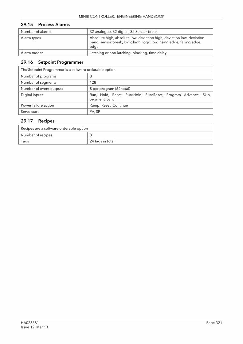
MINI8 CONTROLLER: ENGINEERING HANDBOOK
HA028581 Page 321 Issue 12 Mar 13
29.15 Process Alarms Number of alarms 32 analogue, 32 digital, 32 Sensor break
Alarm types Absolute high, absolute low, deviation high, deviation low, deviation band, sensor break, logic high, logic low, rising edge, falling edge, edge
Alarm modes Latching or non-latching, blocking, time delay
29.16 Setpoint Programmer
The Setpoint Programmer is a software orderable option
Number of programs 8
Number of segments 128
Number of event outputs 8 per program (64 total)
Digital inputs Run, Hold, Reset, Run/Hold, Run/Reset, Program Advance, Skip, Segment, Sync
Power failure action Ramp, Reset, Continue
Servo start PV, SP
29.17 Recipes
Recipes are a software orderable option
Number of recipes 8
Tags 24 tags in total
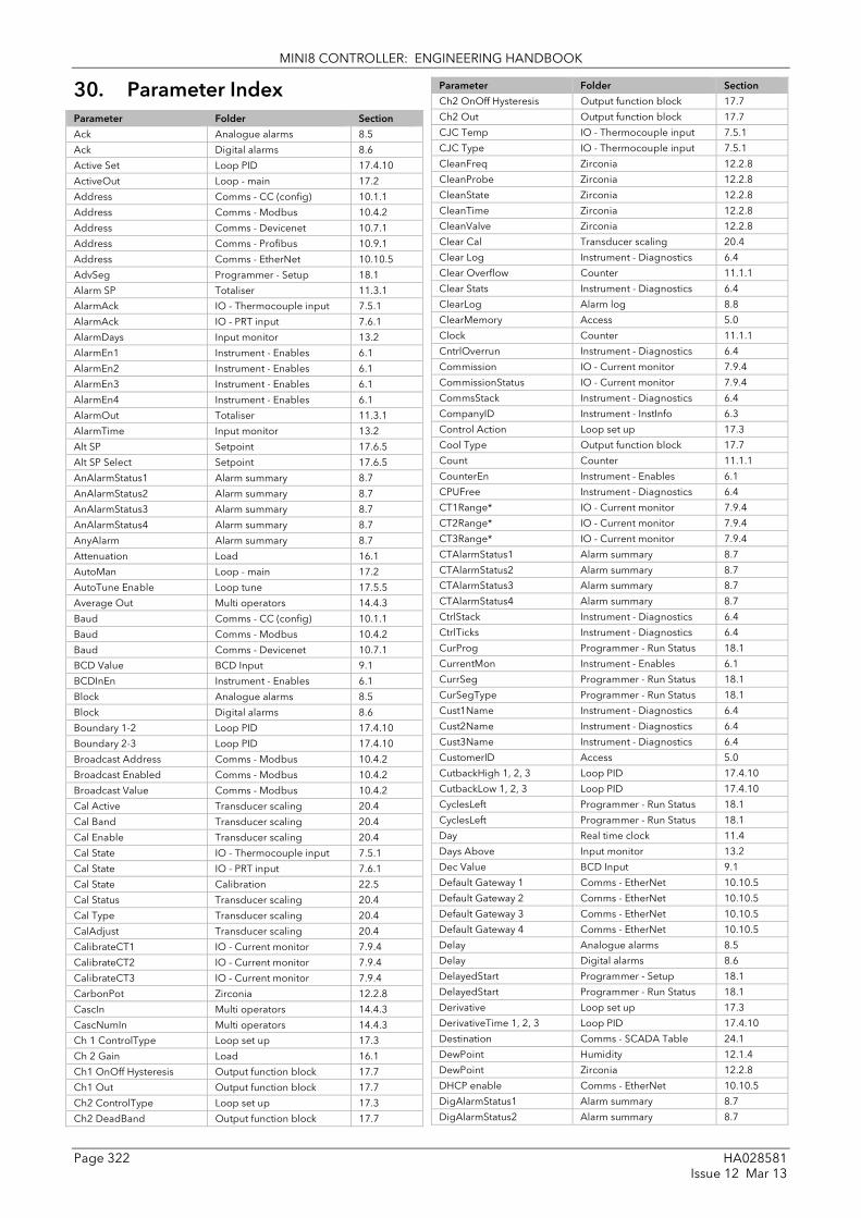
MINI8 CONTROLLER: ENGINEERING HANDBOOK
Page 322 HA028581 Issue 12 Mar 13
30. Parameter Index Parameter Folder Section
Ack Analogue alarms 8.5
Ack Digital alarms 8.6
Active Set Loop PID 17.4.10
ActiveOut Loop - main 17.2
Address Comms - CC (config) 10.1.1
Address Comms - Modbus 10.4.2
Address Comms - Devicenet 10.7.1
Address Comms - Profibus 10.9.1
Address Comms - EtherNet 10.10.5
AdvSeg Programmer - Setup 18.1
Alarm SP Totaliser 11.3.1
AlarmAck IO - Thermocouple input 7.5.1
AlarmAck IO - PRT input 7.6.1
AlarmDays Input monitor 13.2
AlarmEn1 Instrument - Enables 6.1
AlarmEn2 Instrument - Enables 6.1
AlarmEn3 Instrument - Enables 6.1
AlarmEn4 Instrument - Enables 6.1
AlarmOut Totaliser 11.3.1
AlarmTime Input monitor 13.2
Alt SP Setpoint 17.6.5
Alt SP Select Setpoint 17.6.5
AnAlarmStatus1 Alarm summary 8.7
AnAlarmStatus2 Alarm summary 8.7
AnAlarmStatus3 Alarm summary 8.7
AnAlarmStatus4 Alarm summary 8.7
AnyAlarm Alarm summary 8.7
Attenuation Load 16.1
AutoMan Loop - main 17.2
AutoTune Enable Loop tune 17.5.5
Average Out Multi operators 14.4.3
Baud Comms - CC (config) 10.1.1
Baud Comms - Modbus 10.4.2
Baud Comms - Devicenet 10.7.1
BCD Value BCD Input 9.1
BCDInEn Instrument - Enables 6.1
Block Analogue alarms 8.5
Block Digital alarms 8.6
Boundary 1-2 Loop PID 17.4.10
Boundary 2-3 Loop PID 17.4.10
Broadcast Address Comms - Modbus 10.4.2
Broadcast Enabled Comms - Modbus 10.4.2
Broadcast Value Comms - Modbus 10.4.2
Cal Active Transducer scaling 20.4
Cal Band Transducer scaling 20.4
Cal Enable Transducer scaling 20.4
Cal State IO - Thermocouple input 7.5.1
Cal State IO - PRT input 7.6.1
Cal State Calibration 22.5
Cal Status Transducer scaling 20.4
Cal Type Transducer scaling 20.4
CalAdjust Transducer scaling 20.4
CalibrateCT1 IO - Current monitor 7.9.4
CalibrateCT2 IO - Current monitor 7.9.4
CalibrateCT3 IO - Current monitor 7.9.4
CarbonPot Zirconia 12.2.8
CascIn Multi operators 14.4.3
CascNumIn Multi operators 14.4.3
Ch 1 ControlType Loop set up 17.3
Ch 2 Gain Load 16.1
Ch1 OnOff Hysteresis Output function block 17.7
Ch1 Out Output function block 17.7
Ch2 ControlType Loop set up 17.3
Ch2 DeadBand Output function block 17.7
Parameter Folder Section
Ch2 OnOff Hysteresis Output function block 17.7
Ch2 Out Output function block 17.7
CJC Temp IO - Thermocouple input 7.5.1
CJC Type IO - Thermocouple input 7.5.1
CleanFreq Zirconia 12.2.8
CleanProbe Zirconia 12.2.8
CleanState Zirconia 12.2.8
CleanTime Zirconia 12.2.8
CleanValve Zirconia 12.2.8
Clear Cal Transducer scaling 20.4
Clear Log Instrument - Diagnostics 6.4
Clear Overflow Counter 11.1.1
Clear Stats Instrument - Diagnostics 6.4
ClearLog Alarm log 8.8
ClearMemory Access 5.0
Clock Counter 11.1.1
CntrlOverrun Instrument - Diagnostics 6.4
Commission IO - Current monitor 7.9.4
CommissionStatus IO - Current monitor 7.9.4
CommsStack Instrument - Diagnostics 6.4
CompanyID Instrument - InstInfo 6.3
Control Action Loop set up 17.3
Cool Type Output function block 17.7
Count Counter 11.1.1
CounterEn Instrument - Enables 6.1
CPUFree Instrument - Diagnostics 6.4
CT1Range* IO - Current monitor 7.9.4
CT2Range* IO - Current monitor 7.9.4
CT3Range* IO - Current monitor 7.9.4
CTAlarmStatus1 Alarm summary 8.7
CTAlarmStatus2 Alarm summary 8.7
CTAlarmStatus3 Alarm summary 8.7
CTAlarmStatus4 Alarm summary 8.7
CtrlStack Instrument - Diagnostics 6.4
CtrlTicks Instrument - Diagnostics 6.4
CurProg Programmer - Run Status 18.1
CurrentMon Instrument - Enables 6.1
CurrSeg Programmer - Run Status 18.1
CurSegType Programmer - Run Status 18.1
Cust1Name Instrument - Diagnostics 6.4
Cust2Name Instrument - Diagnostics 6.4
Cust3Name Instrument - Diagnostics 6.4
CustomerID Access 5.0
CutbackHigh 1, 2, 3 Loop PID 17.4.10
CutbackLow 1, 2, 3 Loop PID 17.4.10
CyclesLeft Programmer - Run Status 18.1
CyclesLeft Programmer - Run Status 18.1
Day Real time clock 11.4
Days Above Input monitor 13.2
Dec Value BCD Input 9.1
Default Gateway 1 Comms - EtherNet 10.10.5
Default Gateway 2 Comms - EtherNet 10.10.5
Default Gateway 3 Comms - EtherNet 10.10.5
Default Gateway 4 Comms - EtherNet 10.10.5
Delay Analogue alarms 8.5
Delay Digital alarms 8.6
DelayedStart Programmer - Setup 18.1
DelayedStart Programmer - Run Status 18.1
Derivative Loop set up 17.3
DerivativeTime 1, 2, 3 Loop PID 17.4.10
Destination Comms - SCADA Table 24.1
DewPoint Humidity 12.1.4
DewPoint Zirconia 12.2.8
DHCP enable Comms - EtherNet 10.10.5
DigAlarmStatus1 Alarm summary 8.7
DigAlarmStatus2 Alarm summary 8.7
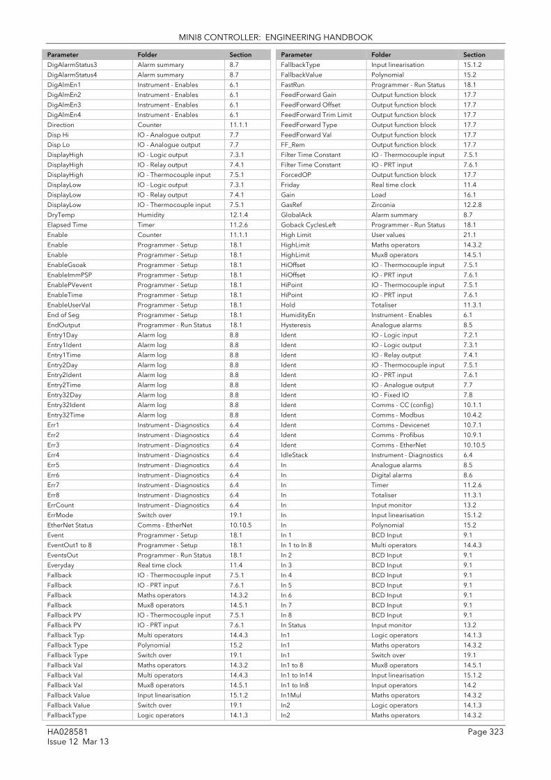
MINI8 CONTROLLER: ENGINEERING HANDBOOK
HA028581 Page 323 Issue 12 Mar 13
Parameter Folder Section
DigAlarmStatus3 Alarm summary 8.7
DigAlarmStatus4 Alarm summary 8.7
DigAlmEn1 Instrument - Enables 6.1
DigAlmEn2 Instrument - Enables 6.1
DigAlmEn3 Instrument - Enables 6.1
DigAlmEn4 Instrument - Enables 6.1
Direction Counter 11.1.1
Disp Hi IO - Analogue output 7.7
Disp Lo IO - Analogue output 7.7
DisplayHigh IO - Logic output 7.3.1
DisplayHigh IO - Relay output 7.4.1
DisplayHigh IO - Thermocouple input 7.5.1
DisplayLow IO - Logic output 7.3.1
DisplayLow IO - Relay output 7.4.1
DisplayLow IO - Thermocouple input 7.5.1
DryTemp Humidity 12.1.4
Elapsed Time Timer 11.2.6
Enable Counter 11.1.1
Enable Programmer - Setup 18.1
Enable Programmer - Setup 18.1
EnableGsoak Programmer - Setup 18.1
EnableImmPSP Programmer - Setup 18.1
EnablePVevent Programmer - Setup 18.1
EnableTime Programmer - Setup 18.1
EnableUserVal Programmer - Setup 18.1
End of Seg Programmer - Setup 18.1
EndOutput Programmer - Run Status 18.1
Entry1Day Alarm log 8.8
Entry1Ident Alarm log 8.8
Entry1Time Alarm log 8.8
Entry2Day Alarm log 8.8
Entry2Ident Alarm log 8.8
Entry2Time Alarm log 8.8
Entry32Day Alarm log 8.8
Entry32Ident Alarm log 8.8
Entry32Time Alarm log 8.8
Err1 Instrument - Diagnostics 6.4
Err2 Instrument - Diagnostics 6.4
Err3 Instrument - Diagnostics 6.4
Err4 Instrument - Diagnostics 6.4
Err5 Instrument - Diagnostics 6.4
Err6 Instrument - Diagnostics 6.4
Err7 Instrument - Diagnostics 6.4
Err8 Instrument - Diagnostics 6.4
ErrCount Instrument - Diagnostics 6.4
ErrMode Switch over 19.1
EtherNet Status Comms - EtherNet 10.10.5
Event Programmer - Setup 18.1
EventOut1 to 8 Programmer - Setup 18.1
EventsOut Programmer - Run Status 18.1
Everyday Real time clock 11.4
Fallback IO - Thermocouple input 7.5.1
Fallback IO - PRT input 7.6.1
Fallback Maths operators 14.3.2
Fallback Mux8 operators 14.5.1
Fallback PV IO - Thermocouple input 7.5.1
Fallback PV IO - PRT input 7.6.1
Fallback Typ Multi operators 14.4.3
Fallback Type Polynomial 15.2
Fallback Type Switch over 19.1
Fallback Val Maths operators 14.3.2
Fallback Val Multi operators 14.4.3
Fallback Val Mux8 operators 14.5.1
Fallback Value Input linearisation 15.1.2
Fallback Value Switch over 19.1
FallbackType Logic operators 14.1.3
Parameter Folder Section
FallbackType Input linearisation 15.1.2
FallbackValue Polynomial 15.2
FastRun Programmer - Run Status 18.1
FeedForward Gain Output function block 17.7
FeedForward Offset Output function block 17.7
FeedForward Trim Limit Output function block 17.7
FeedForward Type Output function block 17.7
FeedForward Val Output function block 17.7
FF_Rem Output function block 17.7
Filter Time Constant IO - Thermocouple input 7.5.1
Filter Time Constant IO - PRT input 7.6.1
ForcedOP Output function block 17.7
Friday Real time clock 11.4
Gain Load 16.1
GasRef Zirconia 12.2.8
GlobalAck Alarm summary 8.7
Goback CyclesLeft Programmer - Run Status 18.1
High Limit User values 21.1
HighLimit Maths operators 14.3.2
HighLimit Mux8 operators 14.5.1
HiOffset IO - Thermocouple input 7.5.1
HiOffset IO - PRT input 7.6.1
HiPoint IO - Thermocouple input 7.5.1
HiPoint IO - PRT input 7.6.1
Hold Totaliser 11.3.1
HumidityEn Instrument - Enables 6.1
Hysteresis Analogue alarms 8.5
Ident IO - Logic input 7.2.1
Ident IO - Logic output 7.3.1
Ident IO - Relay output 7.4.1
Ident IO - Thermocouple input 7.5.1
Ident IO - PRT input 7.6.1
Ident IO - Analogue output 7.7
Ident IO - Fixed IO 7.8
Ident Comms - CC (config) 10.1.1
Ident Comms - Modbus 10.4.2
Ident Comms - Devicenet 10.7.1
Ident Comms - Profibus 10.9.1
Ident Comms - EtherNet 10.10.5
IdleStack Instrument - Diagnostics 6.4
In Analogue alarms 8.5
In Digital alarms 8.6
In Timer 11.2.6
In Totaliser 11.3.1
In Input monitor 13.2
In Input linearisation 15.1.2
In Polynomial 15.2
In 1 BCD Input 9.1
In 1 to In 8 Multi operators 14.4.3
In 2 BCD Input 9.1
In 3 BCD Input 9.1
In 4 BCD Input 9.1
In 5 BCD Input 9.1
In 6 BCD Input 9.1
In 7 BCD Input 9.1
In 8 BCD Input 9.1
In Status Input monitor 13.2
In1 Logic operators 14.1.3
In1 Maths operators 14.3.2
In1 Switch over 19.1
In1 to 8 Mux8 operators 14.5.1
In1 to In14 Input linearisation 15.1.2
In1 to In8 Input operators 14.2
In1Mul Maths operators 14.3.2
In2 Logic operators 14.1.3
In2 Maths operators 14.3.2

MINI8 CONTROLLER: ENGINEERING HANDBOOK
Page 324 HA028581 Issue 12 Mar 13
Parameter Folder Section
In2 Switch over 19.1
In2 Mul Maths operators 14.3.2
Inhibit IO - Current monitor 7.9.4
Inhibit Analogue alarms 8.5
Inhibit Digital alarms 8.6
Inhibit Loop - main 17.2
InHigh Switch over 19.1
InHigh Transducer scaling 20.4
InHighLimit Input linearisation 15.1.2
InHighScale Polynomial 15.2
InInvert Input operators 14.2
InLow Switch over 19.1
InLow Transducer scaling 20.4
InLowLimit Input linearisation 15.1.2
InLowScale Polynomial 15.2
InputSize EtherNet IP 10.11.3
Input Status Multi operators 14.4.3
InstType Instrument - InstInfo 6.3
IntegralTime 1, 2, 3 Loop PID 17.4.10
Interval IO - Current monitor 7.9.4
IntHold Loop - main 17.2
InVal Transducer scaling 20.4
Invert IO - Logic input 7.2.1
Invert IO - Logic output 7.3.1
Invert IO - Relay output 7.4.1
Invert IO - Fixed IO 7.8
Invert Logic operators 14.1.3
IO Type IO - Thermocouple input 7.5.1
IO Type IO - PRT input 7.6.1
IO Type IO - Analogue output 7.7
IO Type IO - Fixed IO 7.8
IOType IO - Logic input 7.2.1
IOType IO - Logic output 7.3.1
IOType IO - Relay output 7.4.1
IP Address 1 Comms - EtherNet 10.10.5
IP Address 2 Comms - EtherNet 10.10.5
IP Address 3 Comms - EtherNet 10.10.5
IP Address 4 Comms - EtherNet 10.10.5
IP Mon En Instrument - Enables 6.1
Latch Analogue alarms 8.5
Latch Digital alarms 8.6
Lgc2 En1 Instrument - Enables 6.1
Lgc2 En2 Instrument - Enables 6.1
Lgc2 En3 Instrument - Enables 6.1
Lgc8 En Instrument - Enables 6.1
Lin Type IO - Thermocouple input 7.5.1
Lin Type IO - PRT input 7.6.1
Lin16Pt En Instrument - Enables 6.1
LinType Polynomial 15.2
Load En Instrument - Enables 6.1
Load En2 Instrument - Enables 6.1
LoOffset IO - Thermocouple input 7.5.1
LoOffset IO - PRT input 7.6.1
Loop En Instrument - Enables 6.1
Loop En2 Instrument - Enables 6.1
LoopBreakTime 1, 2, 3 Loop PID 17.4.10
LoopOutCh1 Load 16.1
LoopOutCh2 Load 16.1
LoPoint IO - Thermocouple input 7.5.1
LoPoint IO - PRT input 7.6.1
Low Limit User values 21.1
LowLimit Maths operators 14.3.2
LowLimit Mux8 operators 14.5.1
MAC1 Comms - EtherNet 10.10.5
MAC2 Comms - EtherNet 10.10.5
MAC3 Comms - EtherNet 10.10.5
Parameter Folder Section
MAC4 Comms - EtherNet 10.10.5
MAC5 Comms - EtherNet 10.10.5
MAC6 Comms - EtherNet 10.10.5
Manual Mode Output function block 17.7
ManualOutVal Output function block 17.7
ManualReset 1, 2, 3 Loop PID 17.4.10
ManualTrack Setpoint 17.6.5
Math2 En1 Instrument - Enables 6.1
Math2 En2 Instrument - Enables 6.1
Math2 En3 Instrument - Enables 6.1
Max Input monitor 13.2
Max Con Tick Instrument - Diagnostics 6.4
Max Events Programmer - Setup 18.1
Max Out Multi operators 14.4.3
Max segments Instrument - Diagnostics 6.4
MaxLeakPh1 IO - Current monitor 7.9.4
MaxLeakPh2 IO - Current monitor 7.9.4
MaxLeakPh3 IO - Current monitor 7.9.4
MaxRcovTime Zirconia 12.2.8
MaxSegsPerProg Instrument - Diagnostics 6.4
Meas Value IO - Analogue output 7.7
Measured Val IO - Logic input 7.2.1
Measured Val IO - Thermocouple input 7.5.1
Measured Val IO - PRT input 7.6.1
Measured Val IO - Fixed IO 7.8
MeasuredVal IO - Logic output 7.3.1
MeasuredVal IO - Relay output 7.4.1
Min Input monitor 13.2
Min Out Multi operators 14.4.3
MinCalTemp Zirconia 12.2.8
MinCPUFree Instrument - Diagnostics 6.4
MinOnTime IO - Logic output 7.3.1
MinOnTime IO - Relay output 7.4.1
MinRcovTime Zirconia 12.2.8
Minutes Comms - SCADA Table 24.1
Mode Real time clock 11.4
Module1 IO - ModIDs 7.1
Module2 IO - ModIDs 7.1
Module3 IO - ModIDs 7.1
Module4 IO - ModIDs 7.1
Monday Real time clock 11.4
Mon-Fri Real time clock 11.4
Mon-Sat Real time clock 11.4
MultiOperEn Instrument - Enables 6.1
Mux8 En Instrument - Enables 6.1
Native Comms - SCADA Table 24.1
Network Status Comms - Profibus 10.9.1
Never Real time clock 11.4
NewAlarm Alarm summary 8.7
NewCTAlarm Alarm summary 8.7
Noise Load 16.1
Num Sets Loop PID 17.4.10
NumIn Input operators 14.2
NumIn Multi operators 14.4.3
NumValidIn Multi operators 14.4.3
Off Day1 & 2 Real time clock 11.4
Off Time1 & 2 Real time clock 11.4
Offset IO - Thermocouple input 7.5.1
Offset IO - PRT input 7.6.1
Offset Load 16.1
On Day1 & 2 Real time clock 11.4
On Time1 & 2 Real time clock 11.4
Oper Logic operators 14.1.3
Oper Input operators 14.2
Oper Maths operators 14.3.2
Out Analogue alarms 8.5

MINI8 CONTROLLER: ENGINEERING HANDBOOK
HA028581 Page 325 Issue 12 Mar 13
Parameter Folder Section
Out Digital alarms 8.6
Out Timer 11.2.6
Out Input monitor 13.2
Out Logic operators 14.1.3
Out Input operators 14.2
Out Maths operators 14.3.2
Out Mux8 operators 14.5.1
Out Input linearisation 15.1.2
Out Polynomial 15.2
Out Switch over 19.1
Out Invert Input operators 14.2
Out1 & 2 Real time clock 11.4
Out1 to Out14 Input linearisation 15.1.2
OutHi Limit Multi operators 14.4.3
OutHighLimit Input linearisation 15.1.2
OutHighScale Polynomial 15.2
OutLo Limit Multi operators 14.4.3
OutLowLimit Input linearisation 15.1.2
OutLowScale Polynomial 15.2
Output High Limit Output function block 17.7
Output Low Limit Output function block 17.7
OutputHi 1, 2, 3 Loop PID 17.4.10
OutputHigh Limit Loop tune 17.5.5
OutputLo 1, 2, 3 Loop PID 17.4.10
OutputLow Limit Loop tune 17.5.5
OutputSize EtherNet IP 10.11.3
OutVal Transducer scaling 20.4
Overflow Counter 11.1.1
Oxygen Zirconia 12.2.8
OxygenExp Zirconia 12.2.8
Parity Comms - CC (config) 10.1.1
Parity Comms - Modbus 10.4.2
Passcode1 Instrument - InstInfo 6.3
Passcode2 Instrument - InstInfo 6.3
Passcode3 Instrument - InstInfo 6.3
PB Units Loop set up 17.3
PID Set Programmer - Setup 18.1
Poly En Instrument - Enables 6.1
PowerFailAct Programmer - Setup 18.1
Pref mstr IP 1 Comms - EtherNet 10.10.5
Pref mstr IP 2 Comms - EtherNet 10.10.5
Pref mstr IP 3 Comms - EtherNet 10.10.5
Pref mstr IP 4 Comms - EtherNet 10.10.5
Pressure Humidity 12.1.4
PrgIn1 & 2 Programmer - Setup 18.1
Probe Type Zirconia 12.2.8
ProbeFault Zirconia 12.2.8
ProbeInput Zirconia 12.2.8
ProbeOffset Zirconia 12.2.8
ProbeStatus Zirconia 12.2.8
Prog En Instrument - Enables 6.1
Prog Hold Programmer - Setup 18.1
Prog Reset Programmer - Setup 18.1
Prog Run Programmer - Setup 18.1
ProgError Programmer - Setup 18.1
ProgPVstart Instrument - Options 6.2
ProgRunHold Programmer - Setup 18.1
ProgRunReset Programmer - Setup 18.1
ProgStatus Programmer - Run Status 18.1
ProgTimeLeft Programmer - Run Status 18.1
ProportionalBand1, 2, 3 Loop PID 17.4.10
Protocol Comms - CC (config) 10.1.1
Protocol Comms - Modbus 10.4.2
Protocol Comms - Devicenet 10.7.1
Protocol Comms - Profibus 10.9.1
Protocol Comms - EtherNet 10.10.5
Parameter Folder Section
PSP Programmer - Run Status 18.1
PSUident Instrument - Diagnostics 6.4
Psychro Const Humidity 12.1.4
PV IO - Logic input 7.2.1
PV IO - Logic output 7.3.1
PV IO - Relay output 7.4.1
PV IO - Thermocouple input 7.5.1
PV IO - PRT input 7.6.1
PV IO - Analogue output 7.7
PV IO - Fixed IO 7.8
PV Loop - main 17.2
PV Out1 Load 16.1
PV Out2 Load 16.1
PVFault Load 16.1
PvFrozen Zirconia 12.2.8
PVIn Programmer - Setup 18.1
PwrFailCount Instrument - Diagnostics 6.4
Range Hi IO - Analogue output 7.7
Range High Setpoint 17.6.5
Range Lo IO - Analogue output 7.7
Range Low Setpoint 17.6.5
Range Max Transducer scaling 20.4
Range Min Transducer scaling 20.4
RangeHigh IO - Logic output 7.3.1
RangeHigh IO - Relay output 7.4.1
RangeHigh IO - Thermocouple input 7.5.1
RangeLow IO - Logic output 7.3.1
RangeLow IO - Relay output 7.4.1
RangeLow IO - Thermocouple input 7.5.1
Rate Setpoint 17.6.5
Rate Output function block 17.7
Rate Disable Setpoint 17.6.5
Rate Disable Output function block 17.7
RateDone Setpoint 17.6.5
RateResolution Programmer - Setup 18.1
ReadOnly Comms - SCADA Table 24.1
Reference Analogue alarms 8.5
RelCh2Gain 1, 2, 3 Loop PID 17.4.10
RelHumid Humidity 12.1.4
RemGasEn Zirconia 12.2.8
RemGasRef Zirconia 12.2.8
RemOPH Output function block 17.7
RemOPL Output function block 17.7
RemoteInput Loop PID 17.4.10
Reset Counter 11.1.1
Reset Totaliser 11.3.1
Reset Input monitor 13.2
ResetEventOuts Programmer - Run Status 18.1
ResetUVal Programmer - Run Status 18.1
Resolution IO - Thermocouple input 7.5.1
Resolution IO - PRT input 7.6.1
Resolution IO - Analogue output 7.7
Resolution Totaliser 11.3.1
Resolution Humidity 12.1.4
Resolution Zirconia 12.2.8
Resolution Maths operators 14.3.2
Resolution Multi operators 14.4.3
Resolution Input linearisation 15.1.2
Resolution Polynomial 15.2
Resolution Load 16.1
Resolution Programmer - Setup 18.1
Resolution User values 21.1
Ripple Carry Counter 11.1.1
RstNewAlarm Alarm summary 8.7
RstNewCTAlarm Alarm summary 8.7
RTClock En Instrument - Enables 6.1

MINI8 CONTROLLER: ENGINEERING HANDBOOK
Page 326 HA028581 Issue 12 Mar 13
Parameter Folder Section
Run Totaliser 11.3.1
Safe OP Val Output function block 17.7
Sat-Sun Real time clock 11.4
Saturday Real time clock 11.4
Sbrk Humidity 12.1.4
SBrk Alarm IO - Thermocouple input 7.5.1
SBrk Alarm IO - PRT input 7.6.1
SBrk Type IO - Thermocouple input 7.5.1
SBrk Type IO - PRT input 7.6.1
SBrk Value IO - Thermocouple input 7.5.1
SBrk Value IO - PRT input 7.6.1
SBrkAlarmStatus1 Alarm summary 8.7
SbrkAlarmStatus2 Alarm summary 8.7
SbrkAlarmStatus3 Alarm summary 8.7
SbrkAlarmStatus4 Alarm summary 8.7
SbrkOp Output function block 17.7
SbrkOutput IO - Thermocouple input 7.5.1
SbrkOutput IO - PRT input 7.6.1
SbyAct IO - Logic output 7.3.1
SbyAct IO - Relay output 7.4.1
SbyAct IO - Fixed IO 7.8
Scale Low Transducer scaling 20.4
Scheduler Loop PID 17.4.10
SchedulerType Loop PID 17.4.10
SegDuration Programmer - Run Status 18.1
Segments Left Instrument - Diagnostics 6.4
SegRate Programmer - Run Status 18.1
SegTarget Programmer - Run Status 18.1
SegTimeLeft Programmer - Run Status 18.1
Select Mux8 operators 14.5.1
SelectIn Switch over 19.1
SensorBreak Mode Output function block 17.7
Serial No Instrument - InstInfo 6.3
Servo Programmer - Setup 18.1
ServoToPV Setpoint 17.6.5
ShuntOut Transducer scaling 20.4
SkipSeg Programmer - Setup 18.1
SootAlm Zirconia 12.2.8
Source Comms - SCADA Table 24.1
SP HighLimit Setpoint 17.6.5
SP LowLimit Setpoint 17.6.5
SP Select Setpoint 17.6.5
SP Track Setpoint 17.6.5
SP Trim Setpoint 17.6.5
SP1 Setpoint 17.6.5
SP2 Setpoint 17.6.5
SPIn Programmer - Setup 18.1
SPIntBal Setpoint 17.6.5
SPTrim HighLimit Setpoint 17.6.5
SPTrim LowLimit Setpoint 17.6.5
Stage Loop tune 17.5.5
Stage Time Loop tune 17.5.5
Standby Access 5.0
Start Cal Transducer scaling 20.4
Start HighCal Transducer scaling 20.4
Start Tare Transducer scaling 20.4
State Loop tune 17.5.5
Status IO - Thermocouple input 7.5.1
Status IO - PRT input 7.6.1
Status IO - Analogue output 7.7
Status Comms - Devicenet 10.7.1
Status Logic operators 14.1.3
Status Maths operators 14.3.2
Status Mux8 operators 14.5.1
Status Polynomial 15.2
Status Switch over 19.1
Parameter Folder Section
Status Transducer scaling 20.4
Status User values 21.1
Status Calibration 22.5
Subnet Mask 1 Comms - EtherNet 10.10.5
Subnet mask 2 Comms - EtherNet 10.10.5
Subnet Mask 3 Comms - EtherNet 10.10.5
Subnet Mask 4 Comms - EtherNet 10.10.5
Sum Out Multi operators 14.4.3
Sunday Real time clock 11.4
Switch High Switch over 19.1
Switch Low Switch over 19.1
SwOver En Instrument - Enables 6.1
SyncIn Programmer - Setup 18.1
Tare Value Transducer scaling 20.4
Target Counter 11.1.1
TargetSP Loop - main 17.2
TempInput Zirconia 12.2.8
TempOffset Zirconia 12.2.8
Tens BCD Input 9.1
Threshold Analogue alarms 8.5
Threshold Input monitor 13.2
Thursday Real time clock 11.4
Time Timer 11.2.6
Time Real time clock 11.4
Time Above Input monitor 13.2
Time2Clean Zirconia 12.2.8
TimeConst1 Load 16.1
TimeConst2 Load 16.1
Timer En Instrument - Enables 6.1
Tolerance Zirconia 12.2.8
Totalise En Instrument - Enables 6.1
TotalOut Totaliser 11.3.1
Track Enable Output function block 17.7
Track PV Setpoint 17.6.5
Track SP Setpoint 17.6.5
TrackOutVal Output function block 17.7
Triggered Timer 11.2.6
TrScale En Instrument - Enables 6.1
Tuesday Real time clock 11.4
Type Analogue alarms 8.5
Type Digital alarms 8.6
Type Timer 11.2.6
Type Load 16.1
Type Loop set up 17.3
UnitID Enable Comms - EtherNet 10.10.5
Units Instrument - Options 6.2
Units IO - Thermocouple input 7.5.1
Units IO - PRT input 7.6.1
Units BCD Input 9.1
Units Totaliser 11.3.1
Units Maths operators 14.3.2
Units Multi operators 14.4.3
Units Input linearisation 15.1.2
Units Polynomial 15.2
Units Load 16.1
Units Programmer - Setup 18.1
Units User values 21.1
UserStringCharSpace Instrument - Diagnostics 6.4
UserStringCount Instrument - Diagnostics 6.4
UsrVal En1 Instrument - Enables 6.1
UsrVal En2 Instrument - Enables 6.1
UsrVal En3 Instrument - Enables 6.1
UsrVal En4 Instrument - Enables 6.1
UValName Programmer - Setup 18.1
Val User values 21.1
Version Instrument - InstInfo 6.3

MINI8 CONTROLLER: ENGINEERING HANDBOOK
HA028581 Page 327 Issue 12 Mar 13
Parameter Folder Section
Wait Comms - CC (config) 10.1.1
Wait Comms - Modbus 10.4.2
WDAct Comms - Modbus 10.4.2
WDAct Comms - Devicenet 10.7.1
WDAct Comms - Profibus 10.9.1
WDAct Comms - EtherNet 10.10.5
WDFlag Comms - Modbus 10.4.2
WDFlag Comms - Devicenet 10.7.1
WDFlag Comms - Profibus 10.9.1
WDFlag Comms - EtherNet 10.10.5
WDTime Comms - Modbus 10.4.2
WDTime Comms - Devicenet 10.7.1
WDTime Comms - Profibus 10.9.1
WDTime Comms - EtherNet 10.10.5
Wednesday Real time clock 11.4
WetOffset Humidity 12.1.4
WetTemp Humidity 12.1.4
WorkingSP Loop - main 17.2
Zirconia En Instrument - Enables 6.1

MINI8 CONTROLLER: ENGINEERING HANDBOOK
Page 328 HA028581 Issue 12 Mar 13


Eurotherm: Internationa
©Copyright Invensys Eurotherm Limited 2013 Invensys, Eurotherm, the Eurotherm logo, Chessell, EurothermSuite, Mini8, Eand Wonderware are trademarks of Invensys plc, its subsidiaries and affiliateowners.
All rights are strictly reserved. No part of this document may be reproduced,neither may it be stored in a retrieval system other than for the purpose to acdocument relates, without the prior written permission of Invensys Eurotherm
Eurotherm Limited pursues a policy of continuous development and producttherefore be changed without notice. The information in this document is giv
Eurotherm Limited will accept no responsibility for any losses arising from er
HA028581/12 (CN29751)
Contact Information
Eurotherm Head Office Faraday Close, Durrington, Worthing, West Sussex, BN13 3PL
Sales Enquiries T +44 (01903) 695888 F 0845 130 9936
General Enquiries T +44 (01903) 268500 F 0845 265982
al sales and support www.euroth
Eycon, Eyris, EPower, EPack nanodac, piccolo, Foxboro, es. All other brands may be trademarks of their respective
modified or transmitted in any form by any means, ct as an aid in operating the equipment to which the m Limited.
t improvement. The specifications in this document may ven in good faith, but is intended for guidance only.
rors in this document.
Represented by:
Worldwide Offices www.eurotherm.com/global
Scan for local contacts
herm.com
Mini8 User Manual