
Mini Groove - · PDF file1. Product Packaging Checklist 4 Mini Groove™ 8000MGDC Charger...
32
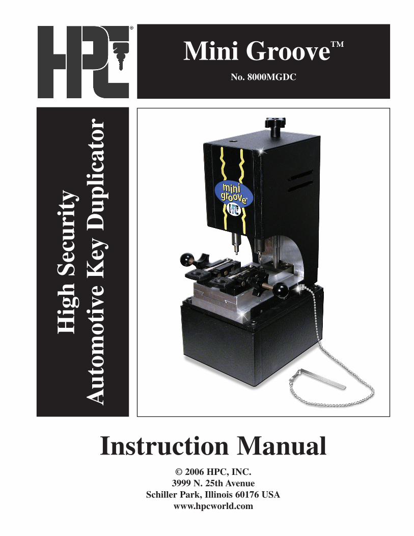
Mini Groove ™ No. 8000MGDC High Security Automotive Key Duplicator Instruction Manual © 2006 HPC, INC. 3999 N. 25th Avenue Schiller Park, Illinois 60176 USA www.hpcworld.com
Transcript of Mini Groove - · PDF file1. Product Packaging Checklist 4 Mini Groove™ 8000MGDC Charger...
Mini Groove™
No. 8000MGDCH
igh
Secu
rity
Aut
omot
ive
Key
Dup
licat
or
Instruction Manual© 2006 HPC, INC.
3999 N. 25th AvenueSchiller Park, Illinois 60176 USA
www.hpcworld.com


Visit us online at:www.hpcworld.com
2Mini Groove™
8000MGDC

Table of Contents
Introduction . . . . . . . . . . . . . . . . . . . . . . . . . . . . . . . . . . . . . . . . . . . . . . . . . .1
1. Product Packaging Checklist . . . . . . . . . . . . . . . . . . . . . . . . . . . . . . . . . . .4
2. Parts Designation . . . . . . . . . . . . . . . . . . . . . . . . . . . . . . . . . . . . . . . . . . . .5
3. Holding and Gauging of Keys . . . . . . . . . . . . . . . . . . . . . . . . . . . . . . . . . .6
4. Cutting Keys . . . . . . . . . . . . . . . . . . . . . . . . . . . . . . . . . . . . . . . . . . . . . . .13
5. Machine Calibration . . . . . . . . . . . . . . . . . . . . . . . . . . . . . . . . . . . . . . . .16
6. Changing The Cutter . . . . . . . . . . . . . . . . . . . . . . . . . . . . . . . . . . . . . . . .22
7. Changing The Lamp . . . . . . . . . . . . . . . . . . . . . . . . . . . . . . . . . . . . . . . .26
8. Charging . . . . . . . . . . . . . . . . . . . . . . . . . . . . . . . . . . . . . . . . . . . . . . . . . .29
9. Exploded View and Parts List . . . . . . . . . . . . . . . . . . . . . . . . . . . . . . . . .30
10. Warranty and Service . . . . . . . . . . . . . . . . . . . . . . . . . . . . . . . . . . . . . . .32
Mini Groove™ Technical Information
RPM: 1800rpmCutter Diameter: 3/32" (2.5mm) - No. CW-332Battery: 12V 7.2 AMP - No. MGDC-38DC Charger: 12VDC 300ma
3Mini Groove™
8000MGDC

1. Product Packaging Checklist
4Mini Groove™
8000MGDC
Charger UnitNo. MGDC-C120
Other Chargers:No. MGDC-C240ENo. MGDC-C240UKNo. MGDC-C240AU
Allen Wrench, 1/16"(No. WRENCH-9)
Instruction Manual(No. 8000MGDC-MAN)
DC Cable(No. MGDC-CABLE)
Tracer Locking Nut Wrench(WRENCH-8)
Adjustment Screwdriver(No. MGDC-SD)
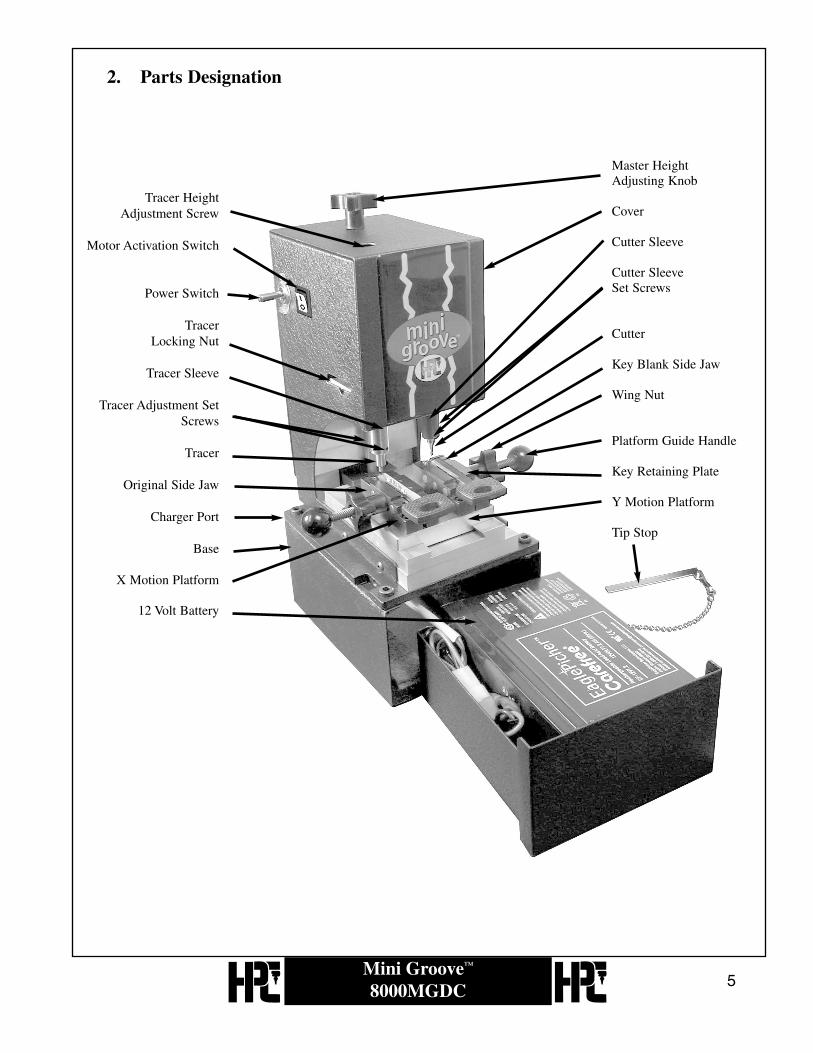
2. Parts Designation
5Mini Groove™
8000MGDC
Master Height Adjusting Knob
Cover
Cutter Sleeve
Cutter SleeveSet Screws
Cutter
Key Blank Side Jaw
Wing Nut
Platform Guide Handle
Key Retaining Plate
Y Motion Platform
Tip Stop
Tracer HeightAdjustment Screw
Motor Activation Switch
Power Switch
Tracer Locking Nut
Tracer Sleeve
Tracer Adjustment SetScrews
Tracer
Original Side Jaw
Charger Port
Base
X Motion Platform
12 Volt Battery

3. Holding And Gauging Of Keys
To ensure accurate duplication, it is imperative to gauge both the original keyand the key blank in exactly the same way.
The original key and the key blank must be flat (not tilted) and held securely inthe jaws.
There are 2 slots in the jaws for inserting the tip stop. Most keys can be gaugedusing the slot at the back of the jaw. Depending on the design of the key andthe length of the blade, some keys should be gauged using the slot closer to thefront of the jaw. Make certain that the key is gauged so that the entire thelength of the key to be cut will be engaged by the tracer and cutter.
6Mini Groove™
8000MGDC

Depending on the design of the keys, it may be necessary to use the Key Retaining Plates on top of the jaws to hold the keys securely.
To utilize the Key Retaining Plates, loosen the two set screws on each plate,slide the plate over the key, and tighten the screws. Make certain that the platesdo not interfere with the tracks to be traced and cut.
7Mini Groove™
8000MGDC

• Gauge and secure the original key.
• Before loading the key blank, adjust the cutter and tracer height to properlyengage the track of the key. Position the carriage so that the tracer is over thetrack of the key. Using the Height Adjusting Knob, lower the tracer so that ittouches the key (in a cut position) and impedes movement of the carriage.Raise the tracer just enough to allow the carriage to move freely. The tracershould be at the bottom of the track.
• With the tracer properly positioned, gauge and secure the key blank in thesame manner as the original key.
8Mini Groove™
8000MGDC

4. Cutting Keys
• Switch the Power Switch to ON.
• Switch the Motor Activation Switch to ON.
9Mini Groove™
8000MGDC

Guide the platform inward and use the tracer to follow the angles of the cutalong one side of the key, then back out the platform guiding the tracer alongthe other side of the key. The cutter will cut an identical path on the key blank.Keep tracing until all of the key has been cut.
10Mini Groove™
8000MGDC

Switch off the Motor Activation Switch, and repeat the gauging and cutting procedures on the other side of the key.
Note: these keys are usually cut the same on both sides. It is usually not necessary to flip the original key to trace the other side.
11Mini Groove™
8000MGDC

5. Machine Calibration
Calibrating the machine is done by adjusting the tracer and/or cutter to ensure that they are at exactly the same height.
12Mini Groove™
8000MGDC
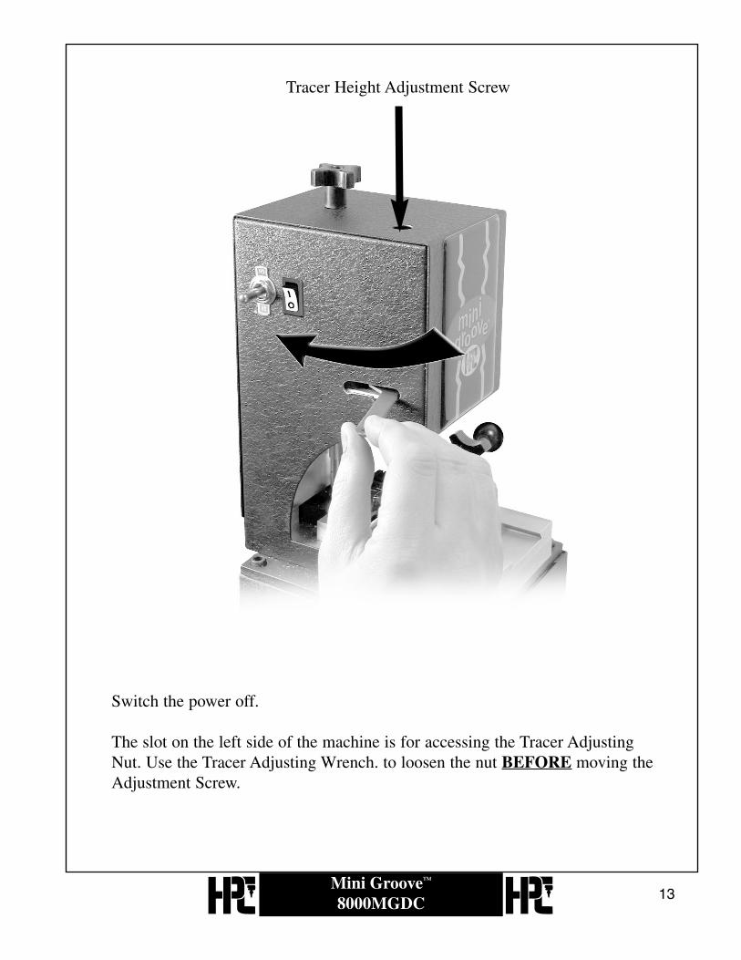
Tracer Height Adjustment Screw
Switch the power off.
The slot on the left side of the machine is for accessing the Tracer AdjustingNut. Use the Tracer Adjusting Wrench. to loosen the nut BEFORE moving theAdjustment Screw.
13Mini Groove™
8000MGDC

To adjust the cutter, you must first be certain that the tracer has beenloosened. Use the small flat screwdriver provided to lower or raise the tracer spindle.
14Mini Groove™
8000MGDC

The calibration is performed using a small piece of paper between the topof the jaw and the cutter and the tracer. This is done to prevent damageto these as well as the internal components of this machine.
1. Place a small piece of paper betweenthe cutter and the top of the jaw.
2. While moving the paper back and forth,use the Master Height Adjusting Knob to lower the cutter just until the paper is heldfirmly under the cutter. Note: if the paper cannot be held firmly under the cutter, this indicates that the tracer is too low, and should first be raised.
3. Remove the paper from under the cutter and place it under the tracer.4. While moving the paper back and forth, use the Tracer Adjustment Screw to lower the
paper just until the paper is held firmly under the tracer. 5. Tighten the Tracer Adjusting Nut.
The machine is now calibrated and ready to cut.
15Mini Groove™
8000MGDC

6. Changing the Cutter
When the cutter becomes worn you will need to replace it with a new cutter. The cutter is held in place by 2 set screws on either side of the collet.
16Mini Groove™
8000MGDC

Loosen both screws with the supplied Allen wrench, and cutter will be easily removed from the collet.
17Mini Groove™
8000MGDC

Install the new cutter and retighten the 2 set screws equally on the flats of cutter. Make sure that the cutter is tight in the collet.
18Mini Groove™
8000MGDC

You will then need to recalibrate your machine to make sure that the tracer and the cutter are equal in height.
Refer to Section 5 for Calibration procedures.
19Mini Groove™
8000MGDC

7. Changing the Lamp
To replace the bulb, you will need to remove the cover over the bulb.Then slide the jaw platform forward until stops, or loosen the release screw in the platform and remove the platform.
Unscrew the lamp cover, and unscrew the bulb from the base of the machine. Replace the worn out bulb with a new one, test the new bulb, and replace the cover.
20Mini Groove™
8000MGDC

8. Charging
21Mini Groove™
8000MGDC
The Mini Groove™ is supplied with a battery charger. This is to be used only forre-charging the battery.
Do not switch the machine on while thecharger is plugged in! When the motor begins to slow down, the battery should be charged for 12-24hours. Connect the charger unit to the machine via the charger port located at theupper right rear section of the machine base. Plug the AC charger into a standard outlet.


23Mini Groove™
8000MGDC
Mini Groove™ Parts List
Number Description Part No.
1 . . . . . . . . . . . . . . . . . . . . . .Locking Knob Retaining Screw . . . . . . . . . . . . . . . . . . . . . . . . . . . . . . . . . . . . . .MGDC-12 . . . . . . . . . . . . . . . . . . . . . .Locking Knob . . . . . . . . . . . . . . . . . . . . . . . . . . . . . . . . . . . . . . . . . . . . . . . . . . .MGDC-23 . . . . . . . . . . . . . . . . . . . . . .Adjustment Rod . . . . . . . . . . . . . . . . . . . . . . . . . . . . . . . . . . . . . . . . . . . . . . . . .MGDC-34 . . . . . . . . . . . . . . . . . . . . . .Power Switch . . . . . . . . . . . . . . . . . . . . . . . . . . . . . . . . . . . . . . . . . . . . . . . . . . .DC-SWITCH5 . . . . . . . . . . . . . . . . . . . . . .Tracer Height Adjustment Rod . . . . . . . . . . . . . . . . . . . . . . . . . . . . . . . . . . . . . .MGDC-56 . . . . . . . . . . . . . . . . . . . . . .Motor Switch . . . . . . . . . . . . . . . . . . . . . . . . . . . . . . . . . . . . . . . . . . . . . . . . . . .MGDC-67 . . . . . . . . . . . . . . . . . . . . . .Adjustment Access Slot (for position only)8 . . . . . . . . . . . . . . . . . . . . . .Cover . . . . . . . . . . . . . . . . . . . . . . . . . . . . . . . . . . . . . . . . . . . . . . . . . . . . . . . . .MGDC-79 . . . . . . . . . . . . . . . . . . . . . .Cover Screw (2) . . . . . . . . . . . . . . . . . . . . . . . . . . . . . . . . . . . . . . . . . . . . . . . . .MGDC-810 . . . . . . . . . . . . . . . . . . . . .Tracer Sleeve . . . . . . . . . . . . . . . . . . . . . . . . . . . . . . . . . . . . . . . . . . . . . . . . . . . .MGDC-911 . . . . . . . . . . . . . . . . . . . . .Set Screws (2) . . . . . . . . . . . . . . . . . . . . . . . . . . . . . . . . . . . . . . . . . . . . . . . . . . .MGDC-1012 . . . . . . . . . . . . . . . . . . . . .Cutter Sleeve . . . . . . . . . . . . . . . . . . . . . . . . . . . . . . . . . . . . . . . . . . . . . . . . . . . .MGDC-1113 . . . . . . . . . . . . . . . . . . . . .Set Screws (2) . . . . . . . . . . . . . . . . . . . . . . . . . . . . . . . . . . . . . . . . . . . . . . . . . . .MGDC-1214 . . . . . . . . . . . . . . . . . . . . .Tracer . . . . . . . . . . . . . . . . . . . . . . . . . . . . . . . . . . . . . . . . . . . . . . . . . . . . . . . . .MGDC-1315 . . . . . . . . . . . . . . . . . . . . .Lamp . . . . . . . . . . . . . . . . . . . . . . . . . . . . . . . . . . . . . . . . . . . . . . . . . . . . . . . . . .MGDC-1416 . . . . . . . . . . . . . . . . . . . . .Lamp Cover . . . . . . . . . . . . . . . . . . . . . . . . . . . . . . . . . . . . . . . . . . . . . . . . . . . .MGDC-1517 . . . . . . . . . . . . . . . . . . . . .Cutter . . . . . . . . . . . . . . . . . . . . . . . . . . . . . . . . . . . . . . . . . . . . . . . . . . . . . . . . .CW-33218 . . . . . . . . . . . . . . . . . . . . .Main Adjusting Rod . . . . . . . . . . . . . . . . . . . . . . . . . . . . . . . . . . . . . . . . . . . . . .MGDC-1719 . . . . . . . . . . . . . . . . . . . . .X Motion Base . . . . . . . . . . . . . . . . . . . . . . . . . . . . . . . . . . . . . . . . . . . . . . . . . .MGDC-1820 . . . . . . . . . . . . . . . . . . . . .Y Motion Base . . . . . . . . . . . . . . . . . . . . . . . . . . . . . . . . . . . . . . . . . . . . . . . . . .MGDC-1921 . . . . . . . . . . . . . . . . . . . . .1/8" x 1/2" Dowel Pin (4) . . . . . . . . . . . . . . . . . . . . . . . . . . . . . . . . . . . . . . . . . .MGDC-2022 . . . . . . . . . . . . . . . . . . . . .Set Screw . . . . . . . . . . . . . . . . . . . . . . . . . . . . . . . . . . . . . . . . . . . . . . . . . . . . . .MGDC-2123 . . . . . . . . . . . . . . . . . . . . .#6-32 x 3/16 Hexagon Socket Set Screw (4) . . . . . . . . . . . . . . . . . . . . . . . . . . . .MGDC-2224 . . . . . . . . . . . . . . . . . . . . .1/4" x 1" Dowel Pin (4) . . . . . . . . . . . . . . . . . . . . . . . . . . . . . . . . . . . . . . . . . . . .MGDC-2325 . . . . . . . . . . . . . . . . . . . . .Right Fixed Jaw (1) . . . . . . . . . . . . . . . . . . . . . . . . . . . . . . . . . . . . . . . . . . . . . . .MGDC-2426 . . . . . . . . . . . . . . . . . . . . .Jaw Tighten Rod (2) . . . . . . . . . . . . . . . . . . . . . . . . . . . . . . . . . . . . . . . . . . . . . .MGDC-2527 . . . . . . . . . . . . . . . . . . . . .Spring (2) . . . . . . . . . . . . . . . . . . . . . . . . . . . . . . . . . . . . . . . . . . . . . . . . . . . . . .MGDC-2628 . . . . . . . . . . . . . . . . . . . . .Right Floating Jaw (1) . . . . . . . . . . . . . . . . . . . . . . . . . . . . . . . . . . . . . . . . . . . . .MGDC-2729 . . . . . . . . . . . . . . . . . . . . .#4-40 x 3/8 Large Hexagon Socket Head Cap Screw (4) . . . . . . . . . . . . . . . . . . .MGDC-2830 . . . . . . . . . . . . . . . . . . . . .Key Retainer (2) . . . . . . . . . . . . . . . . . . . . . . . . . . . . . . . . . . . . . . . . . . . . . . . . .MGDC-2931 . . . . . . . . . . . . . . . . . . . . .Jaw Tighten Knob (2) . . . . . . . . . . . . . . . . . . . . . . . . . . . . . . . . . . . . . . . . . . . . .MGDC-3032 . . . . . . . . . . . . . . . . . . . . .Platform Motion Handle (2) . . . . . . . . . . . . . . . . . . . . . . . . . . . . . . . . . . . . . . . .MGDC-3133 . . . . . . . . . . . . . . . . . . . . .Main Base . . . . . . . . . . . . . . . . . . . . . . . . . . . . . . . . . . . . . . . . . . . . . . . . . . . . . .MGDC-3234 . . . . . . . . . . . . . . . . . . . . .Rubber Foot (4 Incl.) . . . . . . . . . . . . . . . . . . . . . . . . . . . . . . . . . . . . . . . . . . . . . .CM-50133MA 35 . . . . . . . . . . . . . . . . . . . . .Pan Head Machine Screw (4 Incl.) . . . . . . . . . . . . . . . . . . . . . . . . . . . . . . . . . . .CM-5013436 . . . . . . . . . . . . . . . . . . . . .Drawer . . . . . . . . . . . . . . . . . . . . . . . . . . . . . . . . . . . . . . . . . . . . . . . . . . . . . . . .MGDC-3537 . . . . . . . . . . . . . . . . . . . . .Charger Plug Receptacle . . . . . . . . . . . . . . . . . . . . . . . . . . . . . . . . . . . . . . . . . . .MGDC-3638 . . . . . . . . . . . . . . . . . . . . .Hex Nut . . . . . . . . . . . . . . . . . . . . . . . . . . . . . . . . . . . . . . . . . . . . . . . . . . . . . . .MGDC-37 39 . . . . . . . . . . . . . . . . . . . . .Battery . . . . . . . . . . . . . . . . . . . . . . . . . . . . . . . . . . . . . . . . . . . . . . . . . . . . . . . .MGDC-3840 . . . . . . . . . . . . . . . . . . . . .Tip Stop and Chain . . . . . . . . . . . . . . . . . . . . . . . . . . . . . . . . . . . . . . . . . . . . . . .MGDC-3941 . . . . . . . . . . . . . . . . . . . . .Left Side Floating Jaw . . . . . . . . . . . . . . . . . . . . . . . . . . . . . . . . . . . . . . . . . . . . .MGDC-4042 . . . . . . . . . . . . . . . . . . . . .Left Side Fixed Jaw . . . . . . . . . . . . . . . . . . . . . . . . . . . . . . . . . . . . . . . . . . . . . . .MGDC-4143 . . . . . . . . . . . . . . . . . . . . .DC Cable . . . . . . . . . . . . . . . . . . . . . . . . . . . . . . . . . . . . . . . . . . . . . . . . . . . . . .MGDC-42

10. Maintenance, Warranty, and Service
24Mini Groove™
8000MGDC
The carriage can be removed from the platform for easier cleaning. Slidethe carriage to the back of the platform to access the set screw. Removingthis set screw will allow you to slide the carriage off the platform.
CLEANINGRemove all brass chips, dirt, and grit from the surface of your machinedaily with a soft bristle brush. Take particular care in keeping the jaw area clean.

25Mini Groove™
8000MGDC
LUBRICATINGThe carriage and Y-motion platform must remain well lubricated tofacilitate smooth machine operation. Should your machine need lubricating,remove the retaining set screw with the supplied Allen wrench.

26Mini Groove™
8000MGDC
Slide the carriage completely forward, removing it from the Y-motionplatform.

27Mini Groove™
8000MGDC
Turn the carriage over and generously lubricate the dovetail grooves withMobil® A2 or equivalent industrial grease. Be certain to lubricate the areabehind the small brass insert as shown above.

28Mini Groove™
8000MGDC
Lubricate the dovetail grooves of the Y-motion platform similarly. Slidethe Y-motion platform to the right and then to the left for maximumaccess.

29Mini Groove™
8000MGDC
Carefully reinstall the carriage as shown.

30Mini Groove™
8000MGDC
Slide the carriage forward and then replace the set screw.Remember, the set screw should extend above the platform toprevent the carriage from sliding off the platform.

The HPC Service Center
1) The HPC Service Center answers questions involving key machines and related parts Monday through Fridayfrom 8:00 am to 3:30 pm Central Time.
2) REPAIRS — The preventive maintenance and depth calibration are the only repairs or adjustments suggested.Internal operating mechanisms are factory repairable only. Additional repair charges may be incurred byattempting to make these types of repairs yourself.
3) Parts for repairing any HPC key machine can be purchased directly through the Service Center by calling ourtoll-free number: 1-800-323-3295. When ordering any parts over the phone, please have a list of the part numbersand descriptions ready to expedite the ordering process. If the parts are needed in a hurry, they can be sent outUPS Next Day Air or Second Day Air. There is an extra cost incurred when parts are shipped this way.
4) If you need to send an HPC key machine in for repair, please call our Service Center for a repair order number.Pack the machine securely in a box strong enough to prevent damage during shipping. Also be sure that yourmachine is equipped with an HPC cutter when it is sent in for repairs. Include a letter explaining exactly whattype of problem you are having and any other work you may want done on the machine. Make sure your addressand phone number are on the letter as well as the name of someone we can contact if the need arises whilerepairing your machine. Our shipping address is:
HPC, Inc. Attn: Service Center3999 N. 25th AvenueSchiller Park, IL 60176 USAtel: 800.323.3295
5) The usual method of payment for key machine parts is C.O.D. Other methods of payment include Visa,Mastercard or pre-paying your order with a check. If you wish to have your HPC distributor billed for the costof repairs, they will have to call in with approval of the billing and a purchase order for the work being done,before the machine is repaired. Unless otherwise specified, key machines that are not under warranty will beshipped C.O.D. via UPS after the repairs have been made.
6) If you wish for the service department to call you with an estimate for repair of your machine, please specifythis request in writing.
7) If while inspecting your machine our service department discovers additional problems not listed in your note, aservice technician will call you with this information and the estimated charges to repair.
8) If no request is made for HPC to call with a repair estimate, but the cost is expected to exceed $250.00 or 25%of the cost of a new machine, you will be contacted with this information.
9) You will be called if the C.O.D. amount will exceed $250.00.
10) If after informing you of the repair estimate it becomes apparent that the cost will be higher, you will receive acall informing you of the additional charges before any additional work is done.
31Mini Groove™
8000MGDC
WARRANTYThe Mini Groove™ Machine is fully guaranteed for one year from the date of purchase, against factorydefects in material and workmanship. Mail the Warranty Card immediately, to validate your guarantee.Should your machine require factory repairs, please call our Service Department for a Repair Order Number(Tel.: 800.323.3295). The machine should be packed securely, along with a letter clearly stating the nature ofthe problem, and returned to the factory. During the one year warranty period, you will be billed for handlingand shipping only. Neither HPC, Inc. nor HPC distributors have “loaner machines” available.


![Peripheral Damping Yes Line In C] Line Out Shims ..mm Peripheral Damping Yes a No a Washers ...mm Ø Medium Wide (kit) (2 Pip shown) a o Groove 1 Groove 2 Groove Washers ..mm WheelBase](https://static.fdocuments.us/doc/165x107/5f5229a0418d3c074b447355/peripheral-damping-yes-line-in-c-line-out-shims-mm-peripheral-damping-yes-a-no.jpg)
