MINI DOZER M-27 - Movex Innovation To re-assemble, proceed in reverse. Carry out the following step...
22
OPERATING AND MAINTENANCE MANUAL FOR MINI DOZER M-27
Transcript of MINI DOZER M-27 - Movex Innovation To re-assemble, proceed in reverse. Carry out the following step...
OPERATING AND MAINTENANCE MANUAL
FOR
MINI DOZER
M-27

2
TABLE OF CONTENT
OPERATION SECTION
Before using the machine ............................................................................................... 3
Operating time ................................................................................................................ 3
Switching on the Dozer .................................................................................................. 3
Remote control ................................................................................................................ 4
MAINTENANCE SECTION
Lubricating the wheel bearings ..................................................................................... 5
Lubricating the cylinder pivots and the bucket .................................................... 5 - 6
Drive system ............................................................................................................ 7 - 12
Hydraulic pump ........................................................................................................... 12
Hydraulic cylinders .............................................................................................. 13 - 14
Oil filter ......................................................................................................................... 14
Hydraulic valves ........................................................................................................... 15
Dismantling the bucket ................................................................................................ 16
Receiver ......................................................................................................................... 17
Batteries ......................................................................................................................... 18
Track drive motors ....................................................................................................... 19
Hydraulic pump drive.................................................................................................. 20
Technical data Mini-Dozer 27” ........................................................................... 21 - 22

3
Operation Section
BEFORE USING THE MACHINE
Always check to see if any objects will interfere with the movement of the
machine.
Keep the machine clean and free from dust accumulation
OPERATING TIME
You must stop the machine for 10 minutes every hour.
You must stop the machine for one hour after every four hours of use.
SWITCHING ON THE DOZER
To switch on the equipment, pull the red button located at the back of the
machine. A flashing yellow light should turn on.
Turn on the Dozer before activating the remote control.
Press the red button to turn the Dozer off.

4
REMOTE CONTROL
To start the remote control, press the switch indicated by the blue arrow upwards.
A red light should start to flash on the remote.
Turn the red button clockwise. A yellow light should turn on.
The machine is ready to use.
To go forward, back up, turn left or right use the lever indicated by the red arrow.
To raise or lower the mast, push the lever indicated by the yellow arrow, forward
or backward.
To use the bucket, push the lever, indicated by the yellow arrow, to the right or the
left.
Press the red button to turn the remote off.
The three other switches on the remote control are not used and must always
remain in the “off” position.

5
Maintenance Section
LUBRICATING THE WHEEL BEARINGS
Frequency: Once a week (lightly).
LUBRICATING THE CYLINDER PIVOTS AND THE BUCKET
Frequency: Daily, before use. Remove excess grease.

6

7
DRIVE SYSTEM
Proceed as follows for maintenance or repairs to the gear box or electric motors:
Lift the machine and secure it.
Remove the tension on the track (fig. 2).
Take the track apart (fig. 3).
Unplug the power supply to the motor.
Remove the 5 hexagon cylindrical screws (fig. 1 #1, 2, 3, 4, and 5). We now have
the right side of the drive system.
Fig. 1

8
Fig. 2

9
Disassemble the bearing from its support (fig. 3 #2).
Loosen the tightening screw from the threaded collar fig. 3 #3) and remove the
collar.
Remove the nut (fig. 3 #4).
Remove the drive wheel (fig. 3 #5).
Take apart the shaft locking device (fig. 3 #6).
Remove the shaft (fig. 3 #7).
Remove the 4 hexagon cylindrical screws (fig. 3 # 8). We now have the motor-
gear box set.
Fig. 3

10
Before removing the bolts that attach the motor and the gear box, remove the two
plastic plugs by the bear box flange(fig. 4).
Then, align the key’s set screw and the tightening screw from the coupling collar
with the two holes on the gear box.
Then, loosen the two screws.
Fig. 4

11
Now simply remove the 4 hexagon cylindrical screws that attach the motor and
the gear box (fig. 5).
Fig. 5
12
To re-assemble, proceed in reverse.
Carry out the following step before assembling the motor-gear box set.
The motor key must be glued into its keyway using Loctite #242 or equivalent.
Make sure that there is no trace of Loctite on the shaft before inserting it into the
gear box coupling.
After the motor has been bolted to the gear box, tighten the collar and the set
screw on the key.
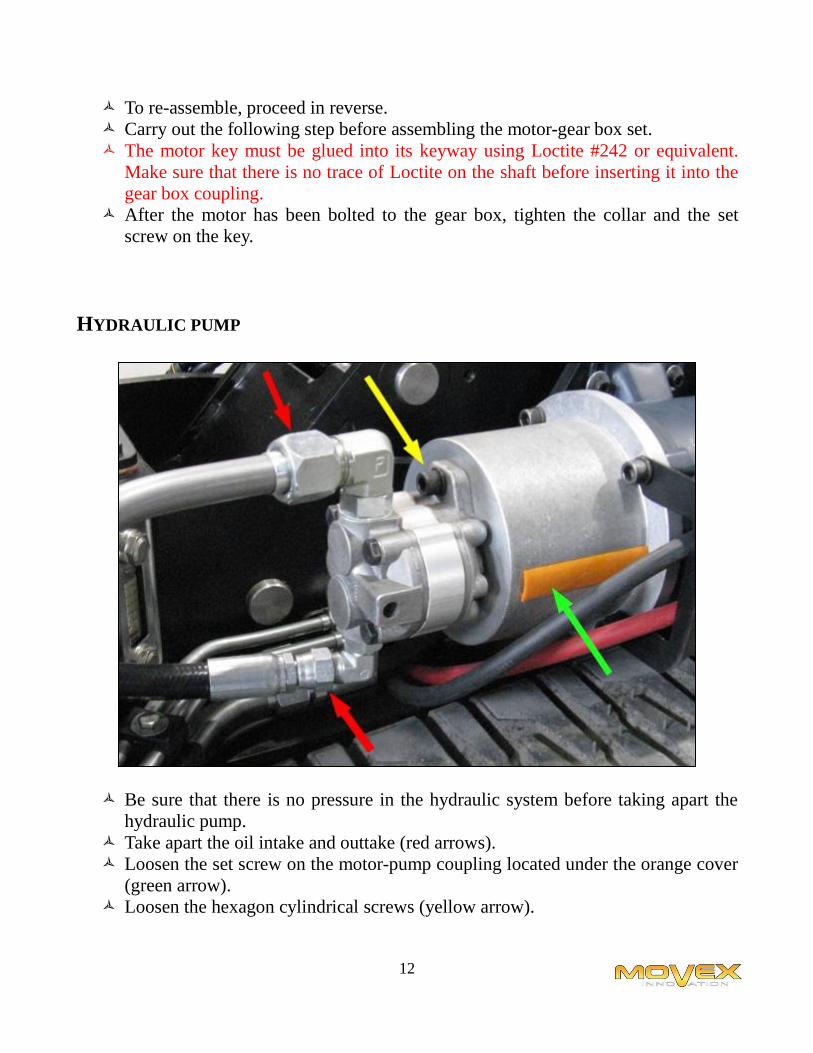
HYDRAULIC PUMP
Be sure that there is no pressure in the hydraulic system before taking apart the
hydraulic pump.
Take apart the oil intake and outtake (red arrows).
Loosen the set screw on the motor-pump coupling located under the orange cover
(green arrow).
Loosen the hexagon cylindrical screws (yellow arrow).

13
HYDRAULIC CYLINDERS
BUCKET CYLINDER
Be sure that there is no pressure in the hydraulic system before taking apart the
hydraulic cylinder.
Take apart the oil intake and outtake (red arrows).
Loosen the hexagon cylindrical screws (green arrows). This allows the two
cylinder fixing pins to be removed.

14
MAST CYLINDER
Be sure that there is no pressure in the hydraulic system before taking apart the
hydraulic cylinder.
Take apart the oil intake and outtake.
Loosen the hexagon cylindrical screws (green arrows). This allows the two
cylinder fixing pins to be removed.
OIL FILTER
Be sure that there is no pressure in the hydraulic system before taking apart the oil
filter.
Unscrew the filter.
Lubricate the seal of the new filter and screw into place.
Chang the oil filter every three months.

15
HYDRAULIC VALVES
Be sure that there is no pressure in the hydraulic system before taking apart a
valve.
Identify the electric connectors before taking apart.
Unbolt the 4 hexagon cylindrical screws (red arrows).
Before replacing the valve, make sure that all the seals are properly positioned.

16
DISMANTLING THE BUCKET
Remove the clip (red arrow).
Remove the fixing pin (green arrow).
Rotate the latch (blue arrow).
Repeat the procedure for the other side.
You can now activate the hydraulic cylinders to remove the bucket.
Proceed in reverse to replace the bucket.
RECEIVER

17
Identify the electric connectors and disconnect them.
Remove the two bolts (red arrows).

18
BATTERIES
To change the batteries, unplug the connector (green arrow) and place it on top of
the batteries.
Place the lifting tool/ (blue arrow) as shown.
Use a 500 Kg, minimum lifting device, to lift the batteries.

19
TRACK DRIVE MOTORS
Identify the electric connectors and disconnect them.
Unbolt the 4 hexagon cylindrical screws (green arrow).
Drive #1 corresponds to the left side of the dozer.
Drive #2 corresponds to the right side of the dozer.

20
HYDRAULIC PUMP DRIVE MOTOR
The drive motor is located behind the battery connector.
Identify the connectors and disconnect them.
Unbolt the 2 hexagon cylindrical screws.

21
MINIDOZER M-27 (Two tracks)
Physical characteristics
Frame Steel
Cabinet Aluminum
Length 112.70 in 2863 mm
Width 27.75 in 705 mm
Height (frame) 22.33 in 567 mm
Height (bucket elevated to max.) 62.5 in 158.75 cm
Clearance underneath bucket (at max. height) 37.5 in 95.25 cm
Weight 2200 lbs 998 kg
Lifting Capacity 642 lbs 241 kg
Bucket Capacity 0.096 cu. Yards 0.073 cu. meters
Linear speed (flat) 66 ft/min 20.1 m/min
Power
Traction Motor 2 HP (x2)
Hydraulic Motor (bucket) 2 HP (x1)
Gearbox 75:1 (x2)
Power Features
Battery included 435 Amps at 6 volts (x4)
AC-DC Charger (external) 1
Battery Pack Amperage 435 Amps (x1)
Operating voltage 24 VDC
BAttery Recharge time 8 hours
Continuous Run-Time 8 hours (flat)
TECHNICAL DATA

22