Mini Blast and Recovery 2011 Rev A - Corrosion · PDF fileMiniBRS BLAST AND RECOVERY SYSTEM...
78
2011 © Axxiom Manufacturing, Inc. MiniBRS BLAST AND RECOVERY SYSTEM OPERATION AND MAINTENANCE MANUAL June 2011 SAVE THIS MANUAL AND MAKE AVAILABLE TO ALL USERS OF THIS EQUIPMENT! Manual Part Number 7200-8033-031-10 Rev. A AXXIOM Manufacturing, Inc. 11927 S. Highway 6, Fresno, Texas 77545 800.231.2085 * 281.431.0581 * fax 281.431.1717 Visit us at www.axxiommfg.com Microsoft Tag inside free app @ http://gettag.mobi
Transcript of Mini Blast and Recovery 2011 Rev A - Corrosion · PDF fileMiniBRS BLAST AND RECOVERY SYSTEM...

2011 © Axxiom Manufacturing, Inc.
MiniBRS BLAST AND RECOVERY SYSTEM OPERATION AND MAINTENANCE MANUAL
June 2011
SAVE THIS MANUAL AND MAKE AVAILABLE TO ALL USERS OF THIS EQUIPMENT!
Manual Part Number 7200-8033-031-10 Rev. A
AXXIOM Manufacturing, Inc. 11927 S. Highway 6, Fresno, Texas 77545
800.231.2085 * 281.431.0581 * fax 281.431.1717
Visit us at www.axxiommfg.com
Microsoft Tag inside free app @ http://gettag.mobi
2 2011 © Axxiom Manufacturing, Inc.
WARNING 1. Any person intending to operate this equipment or any person intending to be in the vicinity during its
operation must receive proper training from his/her supervisor, employer and/or supplier. If this equipment is to be leased or rented, the supplier must assure that the lessee or renter has received proper training before the lessee or renter takes possession of the equipment. Consult Axxiom Manufacturing, Inc.
2. Any person authorized to operate this equipment or any person intending to be in the vicinity during its
operation and who is not capable of reading and understanding this manual must be fully trained regarding the Rules for Safer Operation and all operating procedures, and must be made aware of all the Dangers, Warnings, and Cautions identified herein. Consult Axxiom Manufacturing, Inc.
3. Do Not operate any abrasive blaster or blast equipment before reading and completely understanding all the
warnings, operating procedures and instructions, and the Rules for Safer Operation contained in this manual. 4. Do Not operate any abrasive blaster or blast equipment without following the Rules for Safer Operation and all
the operating procedures and instructions. Failure to properly use blast equipment could result in serious injury or death.
5. Do Not perform any maintenance on any abrasive blaster or blast equipment while it is pressurized. Always
depressurize the abrasive blaster vessel before loading abrasive or performing any maintenance.
6. Do Not use abrasives containing free silica. Silica can cause silicosis or other related respiratory damage. You must wear personal protective equipment for all abrasive blasting operations. Observe all applicable local, state and federal safety regulations in conjunction with airline filters and respiratory protection. Reference OSHA 29 CFR 1910.134.
7. Do Not enter areas during abrasive blasting operations without breathing protection. All personnel in the
vicinity of abrasive blasting operations should wear NIOSH approved air fed respirators, hoods or helmets. 8. Do Not modify or alter any abrasive blaster, blast equipment or controls thereof without written consent from
Axxiom Manufacturing, Inc.
9. Do Not use bleeder type deadman valves on any Schmidt® abrasive blaster. The use of A-BEC, Clemco or a similar bleeder type deadman valve can cause unintentional start-up without warning, which can result in serious personal injury.
10. Do Not sell, rent, or operate abrasive blasters without remote controls. OSHA regulations require remote controls on all blast machines. Failure to use remote controls can cause serious injury or death to the operator(s) or other personnel in the blasting area. Reference OSHA 29 CFR 1910.244(b).
11. Do Not repair or replace any portion of Schmidt® equipment using components that are not Schmidt® original
factory replacement parts. Use of replacement components that are not Schmidt® original factory replacement parts may result in equipment failure which can result in serious personal injury and in addition will void all warranties. Schmidt parts are marked for authentication, please look for the Schmidt name, Schmidt mark, and valve mark. Contact your local authorized Schmidt distributor or contact us for assistance.

© 2011 Axxiom Manufacturing, Inc. 3
This manual contains information needed to operate and maintain your abrasive blaster. Read this entire operations and maintenance manual before using your abrasive blaster. Pay close attention to the Rules for Safer Operation (Section 1.0), and the Dangers, Warnings, and Cautions identified. The purpose of safety symbols and explanations are to alert you of the possible hazards and explain how to avoid them. The safety symbols and explanations do not by themselves eliminate any danger. However, following the instructions given and taking proper accident prevention measures will greatly lower the risk of injury to personnel. Below are the three hazard levels as used in this manual.
WHITE LETTERS with RED BACKGROUND DANGER: Indicates an imminently hazardous situation that, if not avoided, will result in death or serious injury. This signal word is limited to the most extreme situations.
BLACK LETTERS with ORANGE BACKGROUND WARNING: Indicates a potentially hazardous situation that, if not avoided, could result in death or serious injury.
BLACK LETTERS with YELLOW BACKGROUND CAUTION: Indicates a potentially hazardous situation that, if not avoided, may result in minor or moderate injury. It may also be used to alert against unsafe practices that may cause property damage. This manual contains terms that may be specific to the abrasive blast industry. Understanding these terms will help you understand the procedures and instructions given in this manual. Please familiarize yourself with the following terms and refer to them as needed while reading this manual.
Term Definition Pressure Vessel
A fabricated tank (or reservoir) that is part of the abrasive blaster which is filled with compressed air and abrasive. (Also referred to as “blast vessel” or “vessel”.)
Pressurize To manually or automatically fill the abrasive blast vessel with compressed air.
Depressurize To manually or automatically release all the compressed air from inside the abrasive blast vessel. (Also referred to as “blowdown”.)
Blowdown To manually or automatically release all the compressed air from inside the abrasive blast vessel. (Also referred to as “depressurize”.)
Deadman A manually operated valve or switch that allows remote starting and stopping of the blast operation. [Also referred to as “deadman valve” (pneumatic blast controls) or “deadman switch” (electric blast controls.)]
Popup An air pressure operated valve that seals the abrasive inlet at the top of the pressure vessel. Its operation may be manual or automatic.
Abrasive A granular substance used in an air blast operation that is the means for blasting the surface of an object. (Also referred to as abrasive blasting media.)
Silica The crystalline chemical compound silicon dioxide (SiO2) which can be found in many natural abrasives and other substances. Breathing free silica dust can cause respiratory diseases such as silicosis. (Also referred to as crystalline silica)
Instructions for use of manual sections

4 2011 © Axxiom Manufacturing, Inc.
Listed below are the warning decals and the corresponding hazards related to this equipment. Refer to Figure 0.1(a) and 0.1(b) for images of the warning decals. Refer to Figure 0.2 for the locations of these decals on the system.
No. Qty. Part no. Description Hazard
1. 1 7031-001 Medium “Schmidt” Not Applicable
2. 1 7031-054
“Warning” Airborne particle and
loud noise hazard.
Airborne particles and loud noise from blast nozzle and blowdown can cause injury and loss of hearing. Wear approved eye and ear protection. See Section 1.0 and 3.10.
3. 1 7031-007A “Danger”
Pressurized vessel.
Propelled objects will cause serious injury or death. Depressurize vessel prior to performing any maintenance. See Section 6.2.
4. 1 7031-057 “Warning”
Read manual before using this machine.
Read and understand operator’s manual before using this machine. Failure to follow operating instructions could result in injury or damage to equipment. See Section 1.0.
5. 1 7031-077 “Warning”
Pinch point hazard.
Vessel pressurization will close popup. Closing popup can pinch and crush. Keep hands and fingers away from popup.
6. 1 7034-001 Welded “Warning” plate
General hazard and advisory notes.
Steel “Warning” plate welded to pressure vessel which is a general list of required actions to take before and during the operation of this equipment. See Section 1.0.
1) 7031-001 2) 7031-054
3) 7031-007A 4) 7031-057
Figure 0.1(a) – Warning decal summary
0.0 Warning Decal Identification and Location

© 2011 Axxiom Manufacturing, Inc. 5
5) 7031-077
6) 7034-001
Figure 0.1(b) – Warning decal summary (continued)

6 2011 © Axxiom Manufacturing, Inc.
Figure 0.2(a) – Warning decal placement

© 2011 Axxiom Manufacturing, Inc. 7
Section Page 0.0 Warning Decal Identification and Location 2 1.0 Rules for Safer Operation 6 2.0 Specifications and General Information 13
3.0 Installation Requirements and Personal Protective Equipment 15
4.0 Abrasive Blast System General Operation 20 5.0 Abrasive Blaster General Operation 21 6.0 Pre-operation Procedures 32
7.0 Operating Instructions 38
8.0 Maintenance and Inspection Instructions 44 9.0 Drawings and Parts Lists 51 10.0 Recommended Spare Parts & Internet Video List 64
11.0 Troubleshooting 65 12.0 Warranty and Reference Information 68
13.0 Blasting Data Tables Back
Table of Contents
8 2011 © Axxiom Manufacturing, Inc.
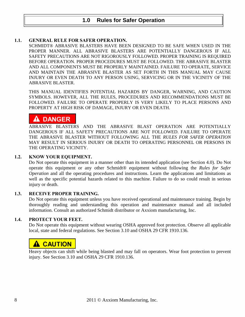
1.1. GENERAL RULE FOR SAFER OPERATION.
SCHMIDT® ABRASIVE BLASTERS HAVE BEEN DESIGNED TO BE SAFE WHEN USED IN THE PROPER MANNER. ALL ABRASIVE BLASTERS ARE POTENTIALLY DANGEROUS IF ALL SAFETY PRECAUTIONS ARE NOT RIGOROUSLY FOLLOWED. PROPER TRAINING IS REQUIRED BEFORE OPERATION. PROPER PROCEDURES MUST BE FOLLOWED. THE ABRASIVE BLASTER AND ALL COMPONENTS MUST BE PROPERLY MAINTAINED. FAILURE TO OPERATE, SERVICE AND MAINTAIN THE ABRASIVE BLASTER AS SET FORTH IN THIS MANUAL MAY CAUSE INJURY OR EVEN DEATH TO ANY PERSON USING, SERVICING OR IN THE VICINITY OF THE ABRASIVE BLASTER.
THIS MANUAL IDENTIFIES POTENTIAL HAZARDS BY DANGER, WARNING, AND CAUTION SYMBOLS. HOWEVER, ALL THE RULES, PROCEDURES AND RECOMMENDATIONS MUST BE FOLLOWED. FAILURE TO OPERATE PROPERLY IS VERY LIKELY TO PLACE PERSONS AND PROPERTY AT HIGH RISK OF DAMAGE, INJURY OR EVEN DEATH.
ABRASIVE BLASTERS AND THE ABRASIVE BLAST OPERATION ARE POTENTIALLY DANGEROUS IF ALL SAFETY PRECAUTIONS ARE NOT FOLLOWED. FAILURE TO OPERATE THE ABRASIVE BLASTER WITHOUT FOLLOWING ALL THE RULES FOR SAFER OPERATION MAY RESULT IN SERIOUS INJURY OR DEATH TO OPERATING PERSONNEL OR PERSONS IN THE OPERATING VICINITY.
1.2. KNOW YOUR EQUIPMENT. Do Not operate this equipment in a manner other than its intended application (see Section 4.0). Do Not
operate this equipment or any other Schmidt® equipment without following the Rules for Safer Operation and all the operating procedures and instructions. Learn the applications and limitations as well as the specific potential hazards related to this machine. Failure to do so could result in serious injury or death.
1.3. RECEIVE PROPER TRAINING. Do Not operate this equipment unless you have received operational and maintenance training. Begin by thoroughly reading and understanding this operation and maintenance manual and all included information. Consult an authorized Schmidt distributor or Axxiom manufacturing, Inc.
1.4. PROTECT YOUR FEET. Do Not operate this equipment without wearing OSHA approved foot protection. Observe all applicable local, state and federal regulations. See Section 3.10 and OSHA 29 CFR 1910.136.
Heavy objects can shift while being blasted and may fall on operators. Wear foot protection to prevent injury. See Section 3.10 and OSHA 29 CFR 1910.136.
1.0 Rules for Safer Operation

© 2011 Axxiom Manufacturing, Inc. 9
1.5. PROTECT YOUR EYES. Do Not operate this equipment without wearing OSHA approved safety glasses. Observe all applicable local, state and federal safety regulations. All operators and personnel in the vicinity must wear OSHA approved eye protection during the operation of this equipment. See Section 3.10 and OSHA 29 CFR 1910.133.
When filling the blast vessel and during the blast operation, abrasive can be blown in the face and eyes of operators. All operators and personnel in the vicinity must wear OSHA approved eye protection during the operation of this equipment. See Section 3.10 and OSHA 29 CFR 1910.133.
1.6. PROTECT YOUR LUNGS. Do Not operate this equipment without wearing OSHA approved respiratory protection. Abrasive blasting produces dust contaminated with toxic substances from the abrasive used, the coating being removed, and the object being blasted. This dust may contain silica which can cause severe and permanent lung damage, cancer, and other serious diseases. Do Not breathe the dust. Do Not rely on your sight or smell to determine if dust is in the air. Silica and other toxic substances may be in the air without a visible dust cloud. If air-monitoring equipment for silica is not provided at the worksite, then all personnel MUST wear appropriate respiratory protection when using or servicing this equipment. Breathing air supplied to respirators must be of acceptable quality. Consult your employer and OSHA regarding the appropriate respiratory protection and breathing air quality. All operators and personnel in the vicinity must wear OSHA approved respiratory protection during the operation of this equipment. See Sections 3.9, 3.10, and OSHA 29 CFR 1910.134.
Abrasive blasting produces dust which may contain silica and other toxic substances that can cause severe and permanent lung damage, cancer, and other serious diseases if inhaled. All operators and personnel in the vicinity must wear OSHA approved respiratory protection during the operation of this equipment. See Sections 3.9, 3.10, and OSHA 29 CFR 1910.134.
1.7. BREATHING AIR QUALITY. Do Not use breathing air that does not meet OSHA Class D standards. Use extreme caution when selecting a source of breathing air. Breathing air provided by an oil-lubricated air compressor can contain carbon monoxide; therefore, use of a carbon monoxide detector is required (See Section 3.10). Carbon monoxide can be in the compressed air produced by an oil-lubricated air compressor when it is operated at extremely high temperature; therefore, a high temperature alarm is required to alert the operators when this condition exists. See Section 3.9 and reference OSHA 29 CFR 1910.134(i).
Extreme caution must be taken when connecting to factory air sources. Factories can have sources of compressed gases such as nitrogen which is fatal if used as a breathing air source. Verify that the air source is breathable air.
Breathing air must meet OSHA Class D standards. Use of breathing air sources that do not meet Class D standards can cause asphyxiation and result in death. Verify that all air sources are breathable quality and use a high-temperature alarm and a carbon monoxide monitor when required. See Sections 3.9, 3.10 and OSHA 29 CFR 1910.134(i).
Enclosed blast areas must be ventilated to reduce airborne dust to an acceptable level as required by OSHA 29 CFR 1910.1000.

10 2011 © Axxiom Manufacturing, Inc.
1.8. PROTECT YOUR HEARING.
Do Not operate this equipment without wearing OSHA approved hearing protection. Observe all applicable local, state and federal safety regulations. All operators and personnel in the vicinity must wear OSHA approved hearing protection during the operation of this equipment. See Section 3.10 and refer to OSHA 29 CFR 1910.95.
Loud noise is generated by the blast nozzle and the blowdown operation of this equipment. All operators and personnel in the vicinity must wear OSHA approved hearing protection during the operation of this equipment. See Section 3.10 and refer to OSHA 29 CFR 1910.95.
1.9. PROTECT YOUR PERSON Abrasive blasting produces dust contaminated with toxic substances from the abrasive used, the coating
being removed, and the object being blasted. All blast operators and other personnel involved in the blast operation or in the vicinity of the blast operation should wear protective clothing. The protective clothing should be disposable or washable work clothes that should be removed at the worksite so that contaminated dust is not transferred into automobiles or homes. See Section 3.10 and refer to OSHA 29 CFR 1910.94 and 1910.134.
1.10. ADHERE TO ALL REGULATIONS. Do Not operate this equipment without observing all local, state, and federal safety regulations including, but not limited to, OSHA (Occupational Health and Safety Administration).
1.11. STAY ALERT. Do Not operate this equipment when you are tired or fatigued. Use caution and common sense while operating and/or performing maintenance on this equipment.
1.12. DO NOT USE DRUGS, ALCOHOL, or MEDICATION. Do Not operate this equipment while under the influence of drugs, alcohol, or any medication.
1.13. PROTECT BYSTANDERS. Do Not allow blast equipment operators and other personnel to enter the vicinity of the blast operation without providing respiratory protective equipment that meets OSHA regulations. If dust concentration levels exceed the limitations set in OSHA 29 CFR 1910.1000 then respirators are required.
1.14. KEEP CHILDREN AND VISITORS AWAY. Do Not allow children or other non-operating personnel to contact this equipment or the connecting hoses and cords. Keep children and non-operating personnel away from work area.
1.15. AVOID DANGEROUS ENVIRONMENTS. Do Not operate this equipment without familiarizing yourself with the surrounding environment. The blast operation creates high level of noise which will prevent the operator from hearing other possible dangers (i.e. traffic or moving equipment). In such situations a stand-by watch person may be necessary to prevent injury to personnel.
1.16. AVOID DANGEROUS ENVIRONMENTS.
Do Not use this equipment in areas cluttered with debris. Debris in the work area can create tripping hazards which can cause the operator to loose control of the blast hose and result in injury to operating personnel. Keep work area clean and well lit. When working at an elevated location, pay attention to articles and persons below.

© 2011 Axxiom Manufacturing, Inc. 11
1.17. AVOID DANGEROUS ENVIRONMENTS. Do Not operate this equipment in elevated areas without using fall protection equipment. Certain applications of this equipment may require the use of scaffolding. Use of scaffolding creates hazardous situations such as tripping and fall hazards which can result in serious injury or death to operating personnel. Consult OSHA 29 CFR 1910 Subpart D.
1.18. AVOID DANGEROUS ENVIRONMENTS. Do Not blast objects that are not properly secured. The blast operation can cause the blasted object to shift or move. Extremely large objects to be blasted can create a crush hazard to operating personnel which can result in serious injury or death. Properly secure the object to be blasted.
1.19. AVOID DANGEROUS ENVIRONMENTS. Do Not blast objects used to store flammable materials. The blast operation can cause sparks which can ignite fumes or residual flammable materials inside enclosed containers which can explode resulting in serious injury or death to operating personnel.
1.20. ELECTRICALLY GROUND EQUIPMENT. Static electricity is generated by the abrasive flow through the blast hose. To prevent static electrical shock to operating personnel only use static dissipating blast hose and install a grounding strap on the abrasive blaster. See Section 5.14.
1.21. MAINTAIN VESSEL INTEGRITY. Do Not operate this equipment with the pressure vessel damaged, or with any part of it worn or
damaged. Do Not operate this equipment in a condition that may cause failure of the pressure vessel. See sections 1.22 through 1.31 below.
An abrasive blaster is a Pressurized Vessel. Alterations, damage, or misuse of the pressure vessel can result in rupturing. Damaged or incorrect components used on the abrasive blaster can result in rupturing. The compressed air inside a pressurized vessel contains a dangerously high level of energy which can propel objects and cause serious injury or death.
1.22. NEVER OPERATE OVER MAXIMUM WORKING PRESSURE. Do Not operate this equipment above maximum allowable working pressure (MAWP) at maximum
operating temperature (°F) shown on the ASME nameplate attached to the vessel. See Section 2.2 and 8.1.
1.23. INSTALL PRESSURE RELIEF DEVICE. Do Not operate this equipment without a pressure relief device in place. The ASME Code requires that all vessels be equipped with pressure relief devices prior to installation. The pressure relief device must be set at the maximum allowable working pressure of the abrasive blaster. See the ASME nameplate attached to the vessel typically located above the handway. See Section 3.11 for information regarding the pressure relief valve.
1.24. NEVER OPERATE BEYOND ALLOWABLE TEMPERATURE RANGE. Do Not operate this equipment above the maximum allowable temperature at the allowable pressure or below the minimum design metal temperature (MDMT) shown on the pressure vessel nameplate. The characteristics of the pressure vessel metal are weakened when the temperature is outside the operating range. Operating the pressure vessel outside of allowable temperature range can result in rupturing and cause serious injury or death. See Section 2.2.

12 2011 © Axxiom Manufacturing, Inc.
1.25. ASME NAMEPLATE REQUIRED. Do Not operate this equipment if the ASME pressure vessel nameplate is missing. Contact Axxiom Manufacturing, Inc. for technical support.
1.26. DO NOT MODIFY VESSEL.
Do Not modify or alter any abrasive blaster, blast equipment, or controls thereof without written consent from Axxiom Manufacturing, Inc. Do Not weld, grind, or sand the pressure vessel. It will not be safe to operate. Non-authorized modifications could lead to serious injury or death. Non-authorized modifications will void the warranty and the ASME certification.
1.27. DO NOT HAMMER ON VESSEL. Do Not hammer on or strike any part of the pressure vessel. Hammering on the pressure vessel can create cracks and cause rupturing.
1.28. FIRE DAMAGE NOTICE. Do Not operate if the pressure vessel has been damaged by fire. If damaged, take out of service immediately and have it inspected and/or repaired by a qualified facility. Contact Axxiom Manufacturing, Inc. for technical support.
1.29. INSPECT VESSEL REGULARLY.
Do Not operate this equipment with damage to the pressure vessel. It is not safe. Inspect outside and inside of the pressure vessel regularly for corrosion or damage (i.e. dents, gouges or bulges). If damaged, take out of service immediately and have it inspected and/or repaired by a qualified facility. Contact Axxiom Manufacturing, Inc. for technical support. See Section 8.0.
1.30. CHECK FOR LEAKS IN VESSEL.
Do Not operate this equipment if there is a leak in the pressure vessel. If leaking, take out of service immediately and have it inspected and/or repaired by a qualified facility. Contact Axxiom Manufacturing, Inc. for technical support.
1.31. NEVER MODIFY BLOWDOWN. Do Not connect the blowdown on this equipment onto a common header with any other unit of any
description, or any other source of compressed air, without first making sure a check valve is used between the header and this unit. Do Not install this equipment sharing piping with another unit of higher discharge pressure and capacity. A safety hazard could occur in the form of a back-flow condition.
1.32. DEPRESSURIZE VESSEL BEFORE PERFORMING MAINTENANCE. Do Not remove, repair, or replace any item on this equipment while it is pressurized. Do Not attempt to
perform maintenance or load abrasive while this equipment is pressurized or is even capable of being pressurized. This means the inlet ball valve should be closed and the air supply should be shut off or disconnected. Anytime the manual blowdown valve is closed it should be assumed that the abrasive blast vessel is pressurized.
An abrasive blaster is a Pressurized Vessel. The compressed air inside a pressurized vessel contains a dangerously high level of energy which can propel objects and cause serious injury or death. Depressurize vessel before performing any maintenance. See Section 6.2.

© 2011 Axxiom Manufacturing, Inc. 13
1.33. ALWAYS USE REMOTE CONTROLS. Do Not sell, rent, or operate abrasive blasters without remote controls. OSHA regulations require remote
controls on all abrasive blasters. All abrasive blasters must be equipped with automatic (deadman) type remote controls (either pneumatic or electric). Failure to use remote controls can cause serious injury or death to the operator(s) or other personnel in the blasting area. Reference OSHA 29 CFR 1910.244(b).
1.34. NEVER USE BLEEDER TYPE DEADMAN VALVES. Do Not use bleeder type deadman valves on any Schmidt® abrasive blaster. The use of A-BEC, Clemco, or a similar bleeder type deadman valve can, without warning, cause unintentional start-up which can result in serious personal injury. A particle of dirt from the air hose can plug the bleed hole in the deadman valve and cause the blast outlet to turn on.
1.35. CHECK FOR DAMAGED PARTS. Do Not use this equipment with damaged components. Damaged components can fail during operation
and result in serious injury or death to operating personnel. Periodically check all valves, hoses, and fittings to see that they are in good condition. Repair any component that shows any sign of wear or leakage. See Section 8.0.
1.36. ALWAYS USE SAFETY PINS ON HOSE COUPLING CONNECTIONS. Do Not use this equipment without hose coupling safety pins in place and hose whip checks installed on
all air and blast hoses. All blast hose couplings and air hose couplings have pin holes that must be safety pinned to prevent accidental disconnections. Accidental hose disconnection can cause serious injury or death. See Section 5.17 and 8.7.
1.37. ALWAYS USE CORRECT REPLACEMENT PARTS AND ACCESSORIES. Do Not use replacement parts or accessories that are not rated for pressures equal to or higher than the abrasive blaster operating pressure. Improper hoses and/or fittings used on, or connected to your abrasive blaster can rupture and cause serious injury or death.
Do Not use replacement parts that are not Schmidt® original factory replacement parts. Non-original parts may not fit properly and can cause equipment damage and/or failure which can result in serious injury to operating personnel. Consult Axxiom Manufacturing, Inc.
Use of replacement components that are not Schmidt® original factory replacement parts may result in equipment failure which can result in serious injury to operating personnel.
1.38. ALWAYS USE CORRECT PRESSURE RATED ACCESSORIES. Do Not use air reservoirs or moisture separator tanks that are not rated for use in compressed air applications. Air reservoirs and moisture separator tanks larger than 6 inches inside diameter must have an ASME code stamp.
An air reservoir or moisture separator tank is a Pressurized Vessel. The compressed air inside a pressurized vessel contains a dangerously high level of energy which can explode propelling objects and result in serious injury or death to operating personnel. Air reservoir and moisture separator tanks must be ASME coded tanks.

14 2011 © Axxiom Manufacturing, Inc.
1.39. NEVER AIM BLAST NOZZLE TOWARDS ANY PERSON. Do Not aim the blast nozzle towards yourself or any person. System malfunction can cause accidental start up and result in injury to personnel.
1.40. NEVER USE ABRASIVE NOT INTENDED FOR BLAST EQUIPMENT. Do Not use abrasive blast abrasive containing free silica. Silica can cause silicosis or other related
respiratory damage. Verify that the abrasive is intended for use in blasting equipment. Personal protective equipment, including airline filters and respirators, must be used for all abrasive blasting operations. Observe all applicable local, state and federal safety regulations. See Section 3.8, 3.10 and reference OSHA 29 CFR 1910.134.
1.41. CHECK ABRASIVE FOR DEBRIS. Do Not use blast abrasive that contains trash or other debris. Trash or debris can create a blockage and cause equipment malfunction. Screen recycled abrasive to remove trash.
1.42. STOP OPERATION IMMEDIATELY IF ANY ABNORMALITY IS DETECTED. Do Not operate this equipment if anything abnormal is seen during operation. Stop operation immediately for inspection.
1.43. DO NOT LIFT THE BLAST VESSEL USING THE LIFT EYES. Do Not lift the blast vessel by any point other than the fork pockets. See Section 2.6.
1.44. MAINTAIN WARNING DECALS. Do Not remove, cover, obstruct, or paint over any warnings, cautions, or instructional material attached. Warning decals must be installed, maintained, and located to be visible and with enough light for legibility. See Section 0.0 and 8.12.
1.45. SAVE THIS OPERATION AND MAINTENANCE MANUAL.
Refer to this operation and maintenance manual as needed as well as any additional information included from other manufacturers. Never permit anyone to operate this equipment without having him/her first read this manual and receive proper training. Make this manual readily available to all operating and maintenance personnel. If the manual becomes lost or illegible replace it immediately. This operation and maintenance manual should be read periodically to maintain the highest skill level; it may prevent a serious accident.
1.46. SAFETY REFERENCES See Section 12.4 for safety information sources and contact information. Use these sources to obtain additional information regarding all aspects of blast operation safety.

© 2011 Axxiom Manufacturing, Inc. 15
2.1 Notes to Distributors and Owners 2.1.1. Verify that the deadman, twinline (or cords), and the operation and maintenance manual are
included with the abrasive blaster when it is received. Verify that the deadman, twinline (or cords), and the operation and maintenance manual are included with the abrasive blaster when it is delivered to the purchaser.
2.1.2. This equipment is intended for knowledgeable and experienced users. No person or persons
should be allowed to operate this equipment without first receiving proper training in abrasive blasting operation and use of this equipment.
2.1.3. Immediately notify Axxiom Manufacturing, Inc. of any instances of use of this equipment in any
manner other than the intended application. See Section 4.0. 2.1.4. Only qualified personnel should load and unload this equipment for shipping. The blast vessel
should only be lifted using the fork pockets. See the lifting diagram shown in Section 2.6. 2.1.5. For further information contact: Axxiom Manufacturing, Inc. 11927 South Highway 6
Fresno, Texas 77545 Phone: 1-800-231-2085 Fax: 1-281-431-1717 Website: www.axxiommfg.com
2.1.6 We have inserted URL of instructional videos to supplement the information within this manual. Videos do not take the place of the manual, read and understand manual before operating equipment. This function requires a computer with an internet connection. (For a complete list of instructional videos see Section 10.2)
2.2 MINIBRS Abrasive Blaster Operational Specifications
Maximum Working Pressure 125 psig @ 250°F (see ASME nameplate) Minimum Metal Temperature -20°F @ 125 psig (see ASME nameplate) Air Consumption See Section 13 table 1 Abrasive Consumption See Section 13 table 2 Blast Hose Size See Section 13 table 3 (This unit is included with ½ hose) Electrical requirements See Section 3.7 (If applicable)
Abrasive Capacity Blast vessel: 0.3 cu ft Reclaim hopper: 0.3 cu ft Vacuum System Pneumatic Vacuum Pump (Eductor) 75SCFM @ 100psig supply pressure Weight 335 lbs (Empty) Dimensions 60” H x 22”W x 34”L 2.3 Important Reference Numbers
Fill in the Abrasive Blaster model number and serial number in the blank spaces below. These will be used for reference whenever service or maintenance is required.
Blaster Model Number
Blaster Serial Number National Board Number
2.0 Specifications and General Information

16 2011 © Axxiom Manufacturing, Inc.
2.4 Vessel Information
2.4.1. All pressure vessels used in Schmidt® Abrasive Blasters are manufactured in strict accordance with the provisions of the ASME Code Section VIII, Div. 1. Please contact your local authorized distributor with your serial number ready to obtain a Manufacturer’s Data Report.
2.4.2. In order to maintain the high level of quality and quality control used in the manufacture of this vessel, it is required that any and all welded repairs to this vessel be performed by a reputable shop holding a National Board “R” Stamp. Welding on the vessel performed by welders not properly qualified per the ASME Code voids the ASME/NB integrity of that particular vessel.
2.5 Notes
2.6 MINIBRS Abrasive Blaster Handling
The MINIBRS is equipped with wheels and casters for portability. Use properly sized ramp to load system onto transporting vehicle. Secure unit onto pallets for forklift handling.
An abrasive blaster is a Pressurized Vessel. The compressed air inside a pressurized vessel contains a dangerously high level of energy which can propel objects and cause serious injury or death. Depressurize vessel before lifting, moving, or transporting.
Figure 2.6(a) – Mini BRS Lifting Diagram

© 2011 Axxiom Manufacturing, Inc. 17
Figure 2.6(b) – Mini BRS Lifting Dimensions
Position blaster as shown to prevent damage to piping.
Strap blaster to pallet as shown. Fasten straps to screw-in hooks. Refer to Section 2.0 for blaster empty weight.
Figure 2.6(c) – Mini BRS Lifting Dimensions

18 2011 © Axxiom Manufacturing, Inc.
Carefully read and follow all the recommendations regarding the abrasive blast system installation requirements. Improper installation can result in equipment malfunction and significant lost time expenses. Consult an authorized Schmidt® distributor or Axxiom Manufacturing, Inc.
3.1 Abrasive Blast System Installation Location
Mini BRS equipped with handles and wheels is portable and can be rolled to locations where blast jobs are performed. Locate the unit to allow accessibility to the handway and for ease of abrasive filling. Pay close attention to object that may be in the path of the pressure vessel exhaust air (depressurization). See Section 5.7 for system depressurization.
3.2 Compressed Air Requirements (blast nozzle) The blast nozzle size and blast pressure largely determine the compressed air requirements. Available air flow capacity and/or air compressor size must be considered before selecting the blast nozzle size. An air source dedicated to the abrasive blast system is preferred to reduce system pressure drops and back flow of air. If an existing air compressor will be used or a limited air supply is available, then the blast nozzle must be selected based on these conditions. Be aware that as the blast nozzle wears the air demand will increase. See Table 1 in Section 13.0 for air consumption by nozzle size at various pressures.
3.3 Air Compressor Size
Air compressor size is crucial to the operation of the abrasive blast system. Blast nozzle selection and desired productivity must be evaluated to determine the air flow requirements prior to selecting the air compressor size. Sufficient air supply capacity is necessary to maintain the system air pressure. Insufficient air flow capacity will result in reduced blast nozzle pressure and lost productivity. The air compressor must be large enough to supply:
i. The sum of blast air requirements for each nozzle at the highest pressure that will be used (see
Section 13.0, Table 1). ii. The 12 CFM breathing air supplied to each blast operator respirator. NOTE: Reference OSHA
regulations regarding requirements for breathing air, especially when an oil-lubricated air compressor is used.
iii. A 185CFM air compressor should be sufficient to operate this system when equipped with a 75CFM eductor and a #3 blast nozzle.
3.4 Blast System Air Supply Line
The air supply hose and fittings must be rated at a minimum of 125 psi operating pressure. The air supply hose from the air compressor to the blast unit should be at least the same diameter as the air inlet piping (see Section 9.0). This size hose will be large enough to supply the required airflow to operate the blast unit controls and each blast nozzle. See Sections 5.2 and 5.17 for further information on air hose connection. NOTE: If the abrasive blast system will be installed in a permanent location, the inlet connection can be hard piped. Do Not install hard piping that is smaller than the piping size of the blast system. Smaller piping size will reduce the air flow capacity. If other equipment will be using the same source of air as
3.0 Installation Requirements and Personal Protective Equipment

© 2011 Axxiom Manufacturing, Inc. 19
the abrasive blaster, install a check valve at the air inlet. This will prevent air pressure back flow, which will carry abrasive into the blast control system. Hard piping connected to the abrasive blaster must be structurally supported so not to apply any loading on the pressure vessel at the points of connection. Unsupported piping can create bending loads at the connections on the pressure vessel and cause failure. Hard piping connections to the pressure vessel must be designed and installed by qualified personnel experienced with piping systems and the applicable codes pertaining to them.
External loading at piping connection can cause failure of the pressure vessel. Hard piping connected to the pressure vessel must include supports to eliminate the possibility of applying a load on the pressure vessel.
3.5 Blast System Air Pressure The maximum allowable working pressure (MAWP) for the blast unit is stamped on the ASME nameplate attached to the vessel. For most abrasive blast systems the MAWP is 150psig. Do Not exceed the MAWP. An air pressure regulator can be installed to reduce air supply pressure that is higher than the MAWP. To prevent air pressure backflow only use a non-relieving air regulator. Air pressure backflow will carry abrasive from the blast vessel and contaminate the blast control system. CRITICAL: A regulator with sufficient air flow capacity must be selected for proper operation of the blast system. Insufficient air flow capacity will cause pressure drop in the blast system resulting in equipment malfunction, abrasive backflow, and reduced blast productivity.
The MINIBRS System is equipped with an air pressure regulator that allows the option of blasting at low pressure. When blasting at low pressure the air supply to the deadman blast control system must be at least 80psig (see Figure 5.5 and 5.6). The valves in the abrasive blast system are “spring closed” and therefore require at least 80psig to operate properly. The air supply to the blast controls is taken upstream of the regulator to maintain the control air pressure at the inlet pressure.
3.6 Blast System Air Quality Air quality is crucial to the operation of an abrasive blaster. Moisture and contaminants can cause components to malfunction. Moisture condensation in a blast system causes abrasive flow problems. Condensation occurs when the hot vapor-filled compressed air cools as it reaches the abrasive blaster. Water droplets formed during condensation can be absorbed by the abrasive in the blast vessel and prevent it from flowing out of the abrasive valve. Therefore, a moisture removal device installed for the blast system air supply is recommended (i.e. coalescing moisture separator, air-cooled aftercooler or deliquescent dryer). Contact a local authorized Schmidt® distributor or Axxiom Manufacturing, Inc. to locate one near you.
3.7 Electrical Requirements (Applicable to systems with electrical controls)
The MINIBRS Blast System electrical controls requirement is 12VDC with a maximum of 1 amp current. See Section 9.0 for the electrical schematic. Consult local electric codes for requirements for the electrical connection to the MINIBRS Blast system.
Electric shock hazard. Disable the electric power prior to performing any maintenance. Service and maintenance must be performed by a qualified electrician.

20 2011 © Axxiom Manufacturing, Inc.
3.8 Abrasive Selection Abrasive selection is likely the most difficult decision related to the blast operation. Choice of abrasive is based on factors such as blast application type, desired finish, coating requirements, characteristics of object to be blasted, cost, ability to recycle, available equipment, safety, and environmental constraints.
There are many abrasives available that are either natural, manufactured, or processing by-products. Abrasives are available in varying sizes, shapes, and hardness. These characteristics determine the resulting effect on the surface to be blasted and limitations of its use. The effects on the blasted surface are measured by its degree of cleanliness and the surface profile. Standards and required levels of these measurements are established by organizations such as Steel Structures Painting Council (SSPC), National Association of Corrosion Engineers (NACE) and coating manufacturers. See Section 12.5 for contact information of these organizations. Use these sources to obtain information regarding all aspects of surface preparation and abrasive selection guidelines.
The Thompson Valve II abrasive blasters are designed for high production open abrasive blasting with a wide range of abrasives. It is the responsibility of the employer and operators to select the proper abrasive. It is the responsibility of the employer to make certain that the abrasive selected is safe to use for abrasive blasting.
CRITICAL: Always obtain the Material Safety Data Sheet (MSDS) for the abrasive to be used. The MSDS provides the chemical makeup of the abrasive. Do Not use abrasives containing toxic materials. Refer to OSHA 29 CFR for acceptable limits of various toxic substances and additional measures to be taken to protect operating personnel. Always use abrasives containing less than 1% of crystalline silica. Always use a NIOSH approved respirator when handling, loading and cleaning up abrasives. Organic substances which are combustible may only be used in automated blast systems with ventilation that meets OSHA 29 CFR 1910.94.
3.9 Breathing Air Quality (Open Blasting)
All blast operators must be supplied with and required to use NIOSH approved air-fed respirators. Breathing air supplied to these respirators must meet Grade D air quality standards as specified by OSHA 29 CFR 1910.134(i) and the Compressed Gas Association Specifications ANSI/CGA G-7.1. Consult these specifications when selecting a source of breathing air. Breathing air must be clean, dry, contaminant-free, and provided at a pressure and volume specified by NIOSH. Use NIOSH approved air filters on all sources of breathing air. See Section 3.10
Breathing air filters do not remove carbon monoxide or any other toxic gases. Use a carbon monoxide monitor to detect unacceptable levels. Consult OSHA 29 CFR 1910.134(i).
Many sources of breathing air are available such as air cylinders, free-air pumps, oil-less air compressors, and oil lubricated air compressors. The most commonly used is the same air compressor that is used for the blast air which most often is oil lubricated. Breathing air provided by an oil-lubricated air compressor can contain carbon monoxide and therefore requires the use of a carbon monoxide detector (See Section 3.10). Carbon monoxide can be in the compressed air produced by an oil-lubricated air compressor when it is operated at extremely high temperature; therefore, a high temperature alarm is required to alert the operators when this condition exists.
Oil lubricated air compressors can produce carbon monoxide. Carbon monoxide can cause asphyxiation and result in death. Use a high-temperature alarm and a carbon monoxide monitor when an oil lubricated air compressor is used to supply breathing air. Consult OSHA 29 CFR 1910.134(i).

© 2011 Axxiom Manufacturing, Inc. 21
3.10 Personal Protective Equipment (PPE) Abrasive blasting has many hazards that may cause injuries to operators. To protect operators from injury each must be supplied with and required to use Personal Protective Equipment. The Occupational Health and Safety Administration (OSHA) requires the employer to assess the workplace to determine what PPE is necessary and supplied to each operator (Reference 29 CFR 1910 Subpart I). OSHA requires that this equipment meet or be equivalent to standards developed by the American National Standards Institute (ANSI). Figure 3.1 below identifies the minimum personal protective equipment required for each abrasive blast operator. Also identified are the OSHA references for each and the ANSI standard each PPE item must meet. All PPE clothing and equipment should be selected for safe design and quality of construction. Select each for proper fit and for comfort which will encourage operator use.
Figure 3.1 - Personal Protective Equipment
22 2011 © Axxiom Manufacturing, Inc.
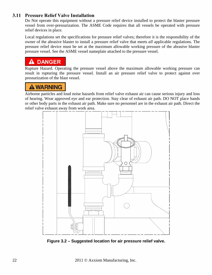
3.11 Pressure Relief Valve Installation Do Not operate this equipment without a pressure relief device installed to protect the blaster pressure vessel from over-pressurization. The ASME Code requires that all vessels be operated with pressure relief devices in place.
Local regulations set the specifications for pressure relief valves; therefore it is the responsibility of the owner of the abrasive blaster to install a pressure relief valve that meets all applicable regulations. The pressure relief device must be set at the maximum allowable working pressure of the abrasive blaster pressure vessel. See the ASME vessel nameplate attached to the pressure vessel.
Rupture Hazard. Operating the pressure vessel above the maximum allowable working pressure can result in rupturing the pressure vessel. Install an air pressure relief valve to protect against over pressurization of the blast vessel.
Airborne particles and loud noise hazards from relief valve exhaust air can cause serious injury and loss of hearing. Wear approved eye and ear protection. Stay clear of exhaust air path. DO NOT place hands or other body parts in the exhaust air path. Make sure no personnel are in the exhaust air path. Direct the relief valve exhaust away from work area.
Figure 3.2 – Suggested location for air pressure relief valve.

© 2011 Axxiom Manufacturing, Inc. 23
3.12 INSTALLATION CHECKLIST (Photocopy this page to use as worksheet.)
□ Deadman/Twinline (or cords): confirm delivery with the abrasive blaster.
□ Blast accessories: confirm receipt as purchased with the blaster.
□ Inspect blaster: check for possible damage during shipment. See Section 8.0 for inspection instructions.
□ Popup alignment: remove popup dust cover from top head and check popup alignment. Shifting of pop-up is possible during shipment. See Section 8.4 for inspection & alignment instructions.
□ Clean blaster: remove handway cover and check for debris inside. Trapped debris can vibrate loose during shipment and later block abrasive flow. If necessary vacuum the bottom of tank. Replace handway cover per instructions in Section 6.3.
□ Accessible location: Position blasters so that handway is accessible for maintenance. See Section 3.1 for additional information.
□ CFM available: determine available air supply (cfm) and record here. See Sections 3.2, 3.3, and 3.5 for information on determining air requirements.
□ Air supply connection: install air supply piping or connect an air supply hose that is the same size as the blaster piping size or larger. See Section 3.4 for details.
□ Air quality: install moisture separator or AirPrep System to remove moisture from blast air supply to protect against abrasive flow problems. See Section 3.6.
□ Electric power: provide power source for electric deadman controls. See Section 3.7.
□ Blast abrasive: select abrasive suited for application. See Section 3.8.
□ Breathing air: provide Grade D air source for blast operators. See Section 3.9.
□ PPE: provide all the necessary personal protective equipment. See Section 3.10.
□ Pressure relief valve: install relief valve if not provided on air compressor. See Section 3.11 for information on pressure relief valve installation.
□ Blast nozzle: select size based on available cfm noted above. See Section 5.13.
□ Blast hose: select size three times the nozzle size to be used. See Section 5.12.
□ Adjust media spider: adjust height per drawing in Section 9.10 (spider is optional).
□ Operator training: all operators must completely read and understand the operation and maintenance manual and be properly trained in equipment and blast operations.
□ Abrasive blaster setup: follow procedure in Section 6.0.

24 2011 © Axxiom Manufacturing, Inc.
The function of the Schmidt® abrasive blaster is to provide a mixture of dry abrasive and compressed air to a blast nozzle. The abrasive blast stream through the blast nozzle is used for removing rust, paint, or other unwanted surface defects. After abrasive blasting, the surface is ready for new paint or coating.
The MINIBRS Abrasive Blaster is one of a group of components used in an abrasive blasting job. The typical components are an air compressor, moisture removal device, an abrasive blaster, blast hose, a blast nozzle, operator personal protective equipment, and blast abrasive. See Figure 4.1.
The blast abrasive is loaded into the abrasive blaster through a top fill port. All the compressed air within the abrasive blaster must be completely vented to atmosphere before it can be filled with abrasive. The abrasive can be bag loaded, or loaded from a Schmidt storage hopper. BRS type units are equipped with vacuum systems that enable them to be pneumatically filled. To begin blasting, the fill port is closed and the abrasive blaster is filled with compressed air from the air compressor. Since moisture creates problems in the blast operation, it is common for the compressed air to be fed through a moisture removal device, such as a Schmidt AirPrep System. The air pressure in the abrasive blast vessel is equal to the air pressure in the blast hose where it connects at the Thompson Valve II. This equal pressure is needed to allow the blast abrasive to flow downward by gravity. The abrasive flow is controlled by the metering valve at the bottom of the blaster. At this point, the blast abrasive flows into the blast air stream and through the blast hose. The speed of blast air and abrasive mixture is greatly increased by the blast nozzle onto the work surface. The high speed of the air and abrasive is what gives it the energy to strip rust and paint off of surfaces. The abrasive blast stream and the dust it creates can be harmful; therefore, unless the dust is adequately contained, all exposed personnel must use personal protective equipment during the blast operation.
All the components required for the blast operation (except for the air compressor) are available from Axxiom Manufacturing, Inc. Contact Axxiom to locate a distributor.
Figure 4.1 – Typical MINIBRS Abrasive Blast System
4.0 Abrasive Blast System General Operation

© 2011 Axxiom Manufacturing, Inc. 25
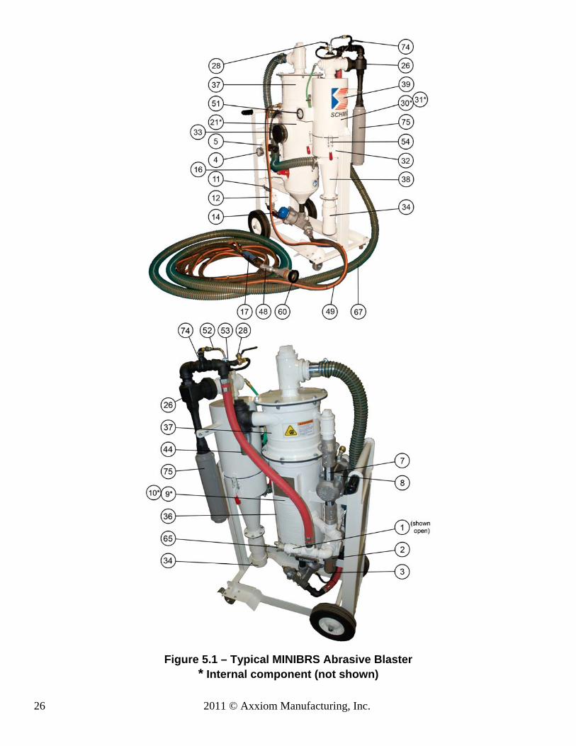
Refer to Figure 5.1 on following page to better understand the general operation of the MINIBRS abrasive blaster. Do not attempt to operate the abrasive blaster before reading all sections of this manual and following all setup procedures. See Sections 5.1 through 5.24 and Section 6.0. The function of the MINIBRS unit is to blast and vacuum recover abrasive media for reuse. The MINIBRS is designed to blast and vacuum abrasive independently, or blast and vacuum simultaneously (closed circuit). The abrasive is contained in the pressure vessel (#36) for blasting. After or during the blast operation the abrasive is recovered in the reclaim hopper (#37) using a vacuum system. Small particles are carried by the vacuum air stream through the reclaimer, through the secondary cyclone (#38), and then into the dust collector (#39). The reusable abrasive is retained in the abrasive reclaimer and drops to the bottom of the reclaim hopper. Large particles (paint chips, cigarette butts, etc) are trapped by the abrasive screen (#21). When the blast vessel is depressurized the abrasive is reloaded from the reclaim hopper. This recycling of the abrasive can be repeated several times depending on the type of abrasive used. After each cycle of the abrasive the particle become smaller and eventually will be carried through the reclaim system and is captured in the cyclone(#38) or dust collector (#39). The dust collector filters the vacuum air and traps the waste dust for disposal. The MINIBRS abrasive blaster (#36) is a depressurized system; meaning the blaster will pressurize only when the Combo Valve(#8) is opened by pressing the deadman lever (#17). Compressed air enters the blast system when the air inlet ball valve (#1) is opened. Air flows through the moisture separator and filter (#2) and into the blast piping and the supply side of the Combo Valve (#8). When the deadman lever (#17) is pressed down signal air will flow back to open the Combovalve (#8) and the automatic air valve (#12). When the Combo Valve opens air will flow into the blast vessel internal piping. The air flow pushes the popup (#10 in Figure 5.2) against the gasket (#9 in Figure 5.2) to seal the abrasive inlet and allow the air flow to pressurize the blast vessel (#36). Blasting starts when the deadman lever (#17) is pressed down opening the Combovalve (#8) and the automatic air valve (#12). Compressed air will flow from the blaster piping to the blast hose (#49) and out through the blast nozzle (#48). The choke ball valve (#11) and the Thompson Valve II (#14) must be open during the blast operation. Abrasive will flow through the Thompson Valve II (#14) and fall into the blast air stream. The abrasive flow can be increased or decreased by turning the knob on top of the Thompson Valve II (#14). Because of the length of the blast hose it will take a few seconds to see changes in abrasive flow. Blasting stops when the deadman lever (#17) is released. This will close the automatic air valve (#12) and the Combo Valve (#8) and depressurize the vessel at the same time. The compressed air in the abrasive blaster will exhaust through the blowdown hose (#7) into the reclaim hopper (#37). MiniBRS Overview Internet Video Link: http://www.youtube.com/watch?v=aCnt1BF1JwU
5.0 MiniBRS Abrasive Blast System General Operation
26 2011 © Axxiom Manufacturing, Inc.
Figure 5.1 – Typical MINIBRS Abrasive Blaster * Internal component (not shown)

© 2011 Axxiom Manufacturing, Inc. 27
5.1 Popup Valve (abrasive inlet) The blaster is filled with abrasive through the abrasive inlet at the top of the pressure vessel. The abrasive inlet is automatically sealed by the popup head (#10) when the blaster is pressurized. The air flow into the internal piping pushes the popup (#10) up against the gasket (#9). See Figure 5.2.
Pinch point hazard. Vessel pressurization will close the popup. Keep fingers clear of the popup opening. Disconnect air supply prior to performing popup maintenance.
Figure 5.2 – Standard Popup Assembly
5.2 Air Supply Connection Air is supplied to the abrasive blaster through a hose connection at the air inlet crowfoot (#65). The air supply hose connected to the abrasive blaster must be same diameter as the air supply piping and rated at a minimum of 125 psi operating pressure. See the drawings and parts lists in Section 9.0 and refer to Sections 3.4 and 5.17.
5.3 Air Inlet Ball Valve The air inlet ball valve (#1) is used to turn on and turn off the air flow to the abrasive blaster. When the inlet ball valve is opened air will flow through the moisture separator (#2) and into the Combo Valve® (#8). In a properly operating MINIBRS system the blast vessel does not pressurize when the inlet ball valve (#1) is opened.
5.4 Moisture Separator Air flow into the MINIBRS Blast System passes through the moisture separator (#2) which removes moisture, oil and dirt particles from the inlet air. The water that is removed by the separator is drained by opening the drain valve (#3) at the bottom of the separator. This ball valve should be left slightly opened anytime the blaster is in operation. This allows water to be drained as it is filtered from the blast air.
28 2011 © Axxiom Manufacturing, Inc.
5.5 Regulated Tank/Blast Pressure Control The MINIBRS Blast System is equipped with an air pressure regulator (#5). The blast vessel and blast air pressure are both adjusted by the air pressure regulator. Reducing the blast air pressure is necessary when blasting objects that are fragile. The pressure is adjusted by turning the knob on top of the regulator valve body (CW-increases pressure, CCW-decreases pressure). The tank/blast pressure is shown by the pressure gauge (#4). Note: The air pressure regulator (#5) is non-relieving which means that when the pressure is decreased by turning the knob, the blast vessel air pressure will not reduce on the pressure gauge. The pressure will reduce only while blasting. The non-relieving feature prevents air from flowing backwards from the blast vessel to the regulator which would carry abrasive.
5.6 Full Pressure Bypass (Not Applicable to MiniBRS) The bypass piping is a detour of the regulated air supply to provide full line pressure to the blast vessel and blast air line. This allows blasting at full pressure for tougher applications without changing the setting of the air pressure regulator (#5). Open ball valve (#6) to bypass the pressure regulator and allow blasting at full air pressure. Then close the ball valve (#6) to resume using the regulated pressure control.
5.7 Combo Valve® (blast vessel pressurization/blowdown) The Combo Valve (#8) is a dual purpose valve that controls both the blast vessel pressurization and the blast operations. At one end the valve pinches the 3/4" blowdown hose (#7) to seal it and allow air to pressurize the blast vessel. At the other end the Combo Valve opens and allows air to flow to the blast vessel (#36) and through the blast air piping to the blast nozzle.
The Combo Valve opens and blasting starts when the deadman lever (#17) is pressed down. The blast vessel will pressurize.
The Combo Valve closes and blasting stops when the deadman lever (#17) is released. The blast vessel will depressurize (blowdown).
When the Combo Valve closes the pinch ram on the blowdown hose (#7) is released and the air inside the blast vessel (#36) will exhaust through the blowdown hose. The blast vessel (#36) remains depressurized when the Combo Valve (#8) is closed. The abrasive blaster must be depressurized before filling with abrasive or before performing any maintenance. (See section 9.4). BRS systems are equipped to enable vacuum loading.
Note: The combo valve blowdown hose (#7) is connected to the reclaim hopper (#37) therefore; the blast vessel exhaust air will vent into the reclaim hopper.
The MINIBRS abrasive blaster is a pressurized vessel. Propelled objects will cause serious injury or death. Read and follow all pre-operation and operating procedures prior to pressurizing the abrasive blaster. See Section 6.0 and 7.0.
Airborne particles and loud noise hazards from blowdown exhaust air can cause serious injury and loss of hearing. Wear approved eye and ear protection. Stay clear of blowdown air path. DO NOT place hands or other body parts in the blowdown air path. Make sure no personnel are in the blowdown air path. Do Not disconnect the blowdown hose (#7) from the reclaim hopper (#37).
© 2011 Axxiom Manufacturing, Inc. 29
5.8 Choke Valve
The choke valve (#11) is a ball valve located in the blast air line upstream of the Thompson Valve II. The choke valve is used to clear any trash that may get into the blast vessel and block the Thompson Valve II orifice. Whenever trash (paint chip, cigarette butt, etc.) blocks the Thompson Valve II orifice the procedure is to fully open the Thompson Valve II knob, then press down the deadman lever (#17) to begin blasting. While blasting, have an assistant close the choke valve completely for about one second. This creates differential pressure at the Thompson Valve II (high pressure above; low pressure below). The higher pressure from the blast vessel should be enough to loosen the trash blocking the Thompson Valve II orifice and blast it through the blast nozzle (#48). To prevent excess wear of the Thompson Valve II keep the choke valve fully open during normal blasting. Note: If the MINIBRS abrasive blaster is equipped with the abrasive cut-off feature set the cut-off valve (or switch) to the on-position for the choke procedure. See Section 9.10.
Do not aim blast nozzle towards yourself or any person. System malfunction can cause accidental start up and result in injury to personnel. A secondary purpose of the choke valve is as a manual shut off valve for the blast air supply. When the choke valve (#11) is closed it will shut off the blast air supply to the blast outlet.
5.9 Automatic Air Valve
The automatic air valve (#12) is a normally closed valve that opens to supply blast air to the blast hose and blast nozzle (#49 & #48). The automatic air valve opens when it receives air to its signal port. This happens when the deadman lever (#17) is pressed down which sends an air signal to the automatic air valve. When the deadman lever is released, the deadman vents the air signal and the automatic air valve spring closes to stop blast air flow to the blast hose and nozzle. See Section 9.7.

30 2011 © Axxiom Manufacturing, Inc.
5.10 Thompson Valve II
The Thompson Valve II (#14) is a dual-purpose valve. First, it is a normally closed valve that opens to supply abrasive into the blast air stream. The Thompson Valve II opens when it receives air to its signal port (See Section 9.5). This happens when the deadman lever (#17) is pressed down which sends an air signal to the Thompson Valve II(#14) and Combovalve(#8). When the deadman lever is released, the air signal vents and Thompson Valve II spring closes to stop abrasive flow to the blast hose and nozzle (#49 & #48). Secondly, the Thompson Valve II (#14) is an abrasive metering valve. When the Thompson Valve II is open the abrasive flow is metered (controlled) by an adjustable orifice. The amount this orifice opens is controlled by turning the knob at the top of the Thompson Valve II. The knob sets the stopping point of the plunger (See Section 9.5). Turn the knob clockwise to reduce the orifice size and decrease the abrasive flow. Turn the knob counter-clockwise to increase the orifice size which will increase the abrasive flow to the blast nozzle (#48). The Thompson Valve II spring retainer has lines on the side to use as reference points to the amount that the orifice is open. Adjustments to the abrasive flow should be made by turning the knob a little at a time. Test the adjustment by starting the blast for a short period to determine if further adjustment is needed. The Thompson Valve II has a built in cleanout port where a ball valve can be installed (see Section 9.5). This ball valve can be used to purge (blow out) trash that blocks abrasive flow. This is done by closing the union ball valve (#13 if equipped), opening the clean out valve, and then pressing down the deadman lever (#17). The blast air flows through the Thompson Valve II and purges any trash through the clean out valve. Note: If the abrasive blaster is equipped with the abrasive cut-off feature set the cut-off valve (or switch) to the on-position for the Thompson Valve II to open for purging. See Sections 9.10.
Airborne particles and loud noise hazards from the purged air can cause serious injury and loss of hearing. Wear approved eye and ear protection. Stay clear of the purged air path. DO NOT place hands or other body parts in the purged air path. Make sure no personnel are in the purged air path.
5.11 Union End Ball Valve (media shutoff not installed on miniBRS) The union ball valve (#13) is used to block the abrasive flow to the Thompson Valve II. This allows the user to remove the Thompson Valve II from the blast vessel without emptying the abrasive. Turn the union ball valve handle to the horizontal position to block abrasive flow. Loosen the nut to separate the two sections of the union ball valve and remove the Thompson Valve II from blast vessel. The handle on the union ball valve can be difficult to turn; however, there are punched holes at each arm of the handle where a standard ratchet wrench can be inserted and used as leverage to open or close the valve (see Figure 5.4).
The MINIBRS abrasive blaster is a Pressurized Vessel. Propelled objects will cause serious injury or death. Depressurize vessel before performing any maintenance. See Section 6.2.

© 2011 Axxiom Manufacturing, Inc. 31
Figure 5.4 – Union End Ball Valve (If Equipped)
5.12 Deadman Valve/Switch The Deadman valve/switch is part of a system that controls the blast operation. The deadman valve/switch (#17) allows the operator to remotely start and stop the blast operation. The Deadman is mounted at the end of the blast hose assembly (#49) close to the blast nozzle (#48) to give the operator easy control of the blast operation.
The Deadman is either a pneumatic valve or an electric switch depending on the type of abrasive blaster control system. When the deadman lever is pressed down it sends either a pneumatic or electric signal to the blast control valve (#15). The control valve opens and sends an air signal to the Combovalve (#8), the automatic air valve (#12) and the Thompson Valve II (#14). See Sections 9.1, 9.2 and 9.8.
Depressing the deadman lever (#17) will start the blast operation. Releasing the deadman lever (#17) will stop the blast operation.
5.12.1. Pneumatic Deadman System: When the pneumatic deadman lever (#17) is pressed down air supply from the orange hose of the twinline hose (#16) flows into the black hose. Air flows through the black hose sending air signals to the Combo Valve® (#8), the automatic air valve (#12), and the Thompson Valve II (#14). When the deadman lever is released, the air signal is cut off and the remaining air vents from the deadman lever (#17). See Figure 5.5 and the drawings in Section 9.1.
Figure 5.5 – Pneumatic Blast Control System
Video Link: http://www.youtube.com/watch?v=oL2EGYQQkPo

32 2011 © Axxiom Manufacturing, Inc.
5.12.2. Electric Deadman System(Optional-If Equipped): When the electric deadman lever is pressed down it closes the electric circuit and supplies electric current to the control valve (#15). The control valve opens and sends air signals to the Combo Valve® (#8), the automatic air valve (#12) and the Thompson Valve II (#14). When the deadman lever is released the electric circuit is cut off closing the control valve. The signal air vents from the breather (#66). See Figure 5.6.
Figure 5.6 – Electric Blast Control System 5.13 Abrasive Cut-Off (Optional-If Equipped)
An optional feature of a blaster is an abrasive cut-off. The purpose of the abrasive cut-off is to allow blasting air without abrasive. This is useful for blowing off abrasive from the blasted item. To blast with air only set the abrasive cut-off valve (or switch) to the off-position then press down the deadman lever (#17). This will send a control signal to the automatic air valve only, therefore only blast air will exit the blast nozzle (#48). For the abrasive cut-off to work a second control valve is needed that provides a signal to the Thompson Valve II separate of the air signal to the automatic air valve. Refer to the drawings in Section 9.10. Note: The abrasive cutoff feature can be added to existing systems. Contact an Axxiom distributor for conversion kit information.
5.14 Blast Hose
The blast air and abrasive mixture flows from the Thompson Valve II to the blast nozzle (#48) through the blast hose assembly (#49). The standard length of the blast hose for the MINIBRS is 25ft; however blast hose extensions can be added for longer lengths. For higher efficiency keep the blast hose as short as possible. Increased blast hose length causes pressure drop at the blast nozzle which reduces the blast efficiency. Keep blast hose as straight as possible. Sharp bends create high wear points. Static electricity is generated by the abrasive flow through the blast hose. To prevent static electrical shock to operating personnel only use static dissipating blast hose and install a grounding strap on the abrasive blaster.
© 2011 Axxiom Manufacturing, Inc. 33
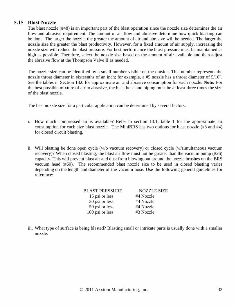
5.15 Blast Nozzle The blast nozzle (#48) is an important part of the blast operation since the nozzle size determines the air flow and abrasive requirement. The amount of air flow and abrasive determine how quick blasting can be done. The larger the nozzle, the greater the amount of air and abrasive will be needed. The larger the nozzle size the greater the blast productivity. However, for a fixed amount of air supply, increasing the nozzle size will reduce the blast pressure. For best performance the blast pressure must be maintained as high as possible. Therefore, select the nozzle size based on the amount of air available and then adjust the abrasive flow at the Thompson Valve II as needed.
The nozzle size can be identified by a small number visible on the outside. This number represents the nozzle throat diameter in sixteenths of an inch; for example, a #5 nozzle has a throat diameter of 5/16". See the tables in Section 13.0 for approximate air and abrasive consumption for each nozzle. Note: For the best possible mixture of air to abrasive, the blast hose and piping must be at least three times the size of the blast nozzle.
The best nozzle size for a particular application can be determined by several factors:
i. How much compressed air is available? Refer to section 13.1, table 1 for the approximate air consumption for each size blast nozzle. The MiniBRS has two options for blast nozzle (#3 and #4) for closed circuit blasting.
ii. Will blasting be done open cycle (w/o vacuum recovery) or closed cycle (w/simultaneous vacuum recovery)? When closed blasting, the blast air flow must not be greater than the vacuum pump (#26) capacity. This will prevent blast air and dust from blowing out around the nozzle brushes on the BRS vacuum head (#60). The recommended blast nozzle size to be used in closed blasting varies depending on the length and diameter of the vacuum hose. Use the following general guidelines for reference:
BLAST PRESSURE NOZZLE SIZE 15 psi or less #4 Nozzle 30 psi or less #4 Nozzle 50 psi or less #4 Nozzle 100 psi or less #3 Nozzle
iii. What type of surface is being blasted? Blasting small or intricate parts is usually done with a smaller nozzle.

34 2011 © Axxiom Manufacturing, Inc.
5.16 BRS Vacuum Head The BRS vacuum head (#60) is an optional accessory used when operating in the closed blasting mode (blasting with simultaneous vacuum recovery). The blast abrasive is contained within the vacuum head where from it is recovered by the vacuum system. The nozzle holder (#48) is integrated with the blast nozzle (#48) which in turn fits into the MiniBRS vacuum head (#60). Then the suction hose attaches to the side of the vacuum head with an adapter (#60e). The vacuum hose to miniBRS head is usually a tight fit, so no further seal is required at that joint. All other joints in the vacuum line are sealed with hose clamps. The BRS is equipped with brushes and a center wear tube that attach to the working end of the head (see Figure 5.7 and Section 9.9). The brushes and center tube are wear components and should be inspected and replaced periodically. When operating in the closed blasting mode requiring the use of a vacuum head assembly, it is important to remember that this limits the size of blast nozzle (#48) that can be used due to limitations created by the blast head and the available compressed air volume. Refer to Sections 3.0 and 13.1 to determine compressed air requirements. Video Link: http://www.youtube.com/watch?v=4YFiwquSKbs Video Link: http://www.youtube.com/watch?v=WPX90lBlaiU
Figure 5.7 – Workhead Connections
5.17 Hose Connection
All air hose, blast hose, and threaded couplings have pin holes that align when connected. To prevent accidental hose disconnections safety pins must be installed through these holes. As a secondary safety measure each hose connection should also include a hose whip check that will hold the hose if there is an accidental disconnection. Connect one loop to each side of the connection and stretch out as shown in Figure 5.8 below. All air hose, blast hose, and threaded couplings have a gasket that seals the connection and should be replaced when air is leaking.
Failure to install safety pins on all air and blast hose couplings can result in hose disconnects and could result in serious injury or death.
© 2011 Axxiom Manufacturing, Inc. 35
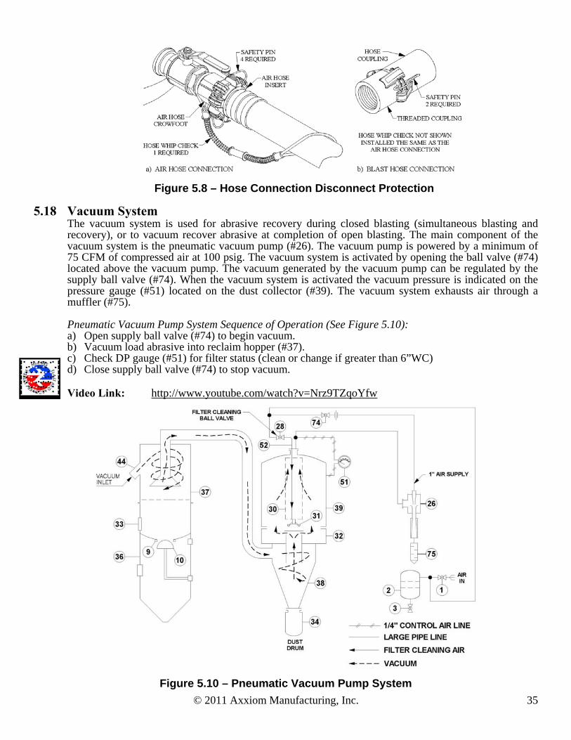
Figure 5.8 – Hose Connection Disconnect Protection
5.18 Vacuum System The vacuum system is used for abrasive recovery during closed blasting (simultaneous blasting and recovery), or to vacuum recover abrasive at completion of open blasting. The main component of the vacuum system is the pneumatic vacuum pump (#26). The vacuum pump is powered by a minimum of 75 CFM of compressed air at 100 psig. The vacuum system is activated by opening the ball valve (#74) located above the vacuum pump. The vacuum generated by the vacuum pump can be regulated by the supply ball valve (#74). When the vacuum system is activated the vacuum pressure is indicated on the pressure gauge (#51) located on the dust collector (#39). The vacuum system exhausts air through a muffler (#75).
Pneumatic Vacuum Pump System Sequence of Operation (See Figure 5.10): a) Open supply ball valve (#74) to begin vacuum. b) Vacuum load abrasive into reclaim hopper (#37). c) Check DP gauge (#51) for filter status (clean or change if greater than 6”WC) d) Close supply ball valve (#74) to stop vacuum. Video Link: http://www.youtube.com/watch?v=Nrz9TZqoYfw
Figure 5.10 – Pneumatic Vacuum Pump System

36 2011 © Axxiom Manufacturing, Inc.
5.19 Non-Adjustable Airwash Reclaim Hopper The function of the abrasive reclaim hopper (#37) is to receive the abrasive recovered by vacuuming. The abrasive and other debris enter the abrasive reclaimer at the inlet (#44). Large heavier particles fall to the bottom of the abrasive reclaimer. Small lighter particles remain in the air stream and are carried from the abrasive reclaimer into the secondary cyclone (#38) then to the dust collector (#39). There is an abrasive screen (#21) inside the reclaimer that prevents debris (paint chips, cigarette butts, etc.) from passing into the pressure vessel (#36). When blasting is interrupted and the pressure vessel is depressurized, the popup valve (#10) opens which allows the abrasive accumulated in the reclaimer to fall through the screen and enter the pressure vessel. The screen (#21) should be inspected and vacuum cleaned periodically. It can be accessed through the access door (#33) of the abrasive reclaimer.
Video Link: http://www.youtube.com/watch?v=icTLHGvKgfI 5.20 Secondary Cyclone
The function of the secondary cyclone (#38) is to provide additional separation of dust particles prior to entering the dust collector (#39). This separation of large and small dust particles will extend the life of the dust collector filter (#30). The air/dust flow enters the cyclone at the tangential inlet. As it enters the velocity is reduced causing the heavier particles to drop out of the air stream and down to the bottom of the cyclone. The cyclone empties into a dust drum (#34) which must be periodically emptied.
Video Link: http://www.youtube.com/watch?v=8dGsSXg5I9g 5.21 Dust collector
The dust-filled vacuum air stream from the secondary cyclone enters the dust collector (#39) where the dust particles are filtered out a pleated cartridge filter (#30). The filter is held in position by a winged knob (#31) which seals it against the bottom of the tube sheet in the dust collector. The air filter can be accessed for removal or inspection by loosening the three latches (#54) to completely remove the dust collector dust bin (#32). To remove the filter (#30), loosen the winged knob (#31) so that it can be removed. The filter must be cleaned regularly to prevent clogging (see Section 5.22) and insure long life (see Section 8.17). Filters requiring maintenance or clogged filters will be apparent by an elevated differential pressure reading on the gauge (#51) [greater than 6”WC] connected to the dust collector. The filtered vacuum air stream is evacuated from the dust collector through the pneumatic vacuum pump (#26). The dust removed from the air stream collects in the removable dust collector bin (#32). The dust collector bin must be periodically emptied for proper function. Push down three latches (#54) to removed dust bin (#32) and empty collected dust.
Abrasive blasting produces dust which may contain Silica and other toxic substances that can cause severe and permanent lung damage, cancer, and other serious diseases if inhaled. Wear OSHA approved respiratory protection when opening the dust collector and/or the dust drum. See Sections 3.8, 3.10, and OSHA 29 CFR 1910.134.
Video Link: http://www.youtube.com/watch?v=20ySiUj0jAg 5.22 Filter Cleaning Wand
The function of the cleaning wand is to clean the cartridge filter (#30) by using compressed air to flush filter by loosening or dislodging the dust particles from the pleated filter surface. The required interval between pulses is determined by the blasting conditions. As the particles begin to clog the filter the differential pressure across the dust collector tube sheet will increase. This increase can be detected on the differential pressure gauge (#51). To clean the filter, make sure that the vacuum system is turned off by closing the eductor ball valve (#74). Loosen the wand compression fitting (#53) by turning counterclockwise. Open the cleaning wand ball valve (#28). The wand (#52) will start flushing the filter. Move wand(#52) up and down while rotating both directions. Video link: http://www.youtube.com/watch?v=tj-zXdfWgIk

© 2011 Axxiom Manufacturing, Inc. 37
Failure to follow the procedures below could result in serious injury or death. In addition to these procedures, completely read and understand all sections of this MINIBRS Abrasive Blaster Operation and Maintenance Manual. 6.1 MINIBRS Abrasive Blaster Setup Procedure (see Figure 6.1)
6.1.1. Static electricity is generated by the abrasive flow through the blast hose. To prevent static
electrical shock to operating personnel only use static dissipating blast hose and install a grounding strap on the abrasive blaster.
6.1.2. Do Not operate this equipment without a pressure relief device in place. The ASME Code requires that all vessels be operated with pressure relief devices.
Local regulations set the specifications for pressure relief valves; therefore it is the responsibility of the owner of the MINIBRS abrasive blaster to install a pressure relief valve that meets all applicable regulations. Refer to Section 3.11 for information regarding the air pressure relief valve.
6.1.3. Verify that all required personal protective equipment is available for each operator and in good operating condition (safety glasses, safety shoes, ear plugs, gloves, airline filter, respirator, & carbon monoxide monitor). Critical: Adhere to all local, state, and federal regulations including, but not limited to, OSHA (Occupational Health and Safety Administration). Pay close attention to requirements regarding breathing air quality. When an oil-lubricated air compressor is used, additional requirements for a high temperature alarm and/or a carbon monoxide monitor become necessary. See Sections 3.9 and 3.10.
Failure to use personal protective equipment could result in serious injury or death.
6.1.4. Close the air inlet ball valve (#1), choke ball valve (#11), and abrasive shut-off valve (#13) if equipped.
6.1.5. Empty the cyclone dust drum (#34) by unscrewing it from below the secondary cyclone (#38).
Reinstall hand tight.
Abrasive blasting produces dust which may contain Silica and other toxic substances that can cause severe and permanent lung damage, cancer, and other serious diseases if inhaled. Wear OSHA approved respiratory protection when opening the dust collector and/or the dust drum. See Sections 3.8, 3.10, and OSHA 29 CFR 1910.134.
Video link: http://www.youtube.com/watch?v=8dGsSXg5I9g
6.1.6. Empty the dust collector dust bin by pushing down on three latches (#54) to remove the dust collector dust bin (#32). Video link: http://www.youtube.com/watch?v=20ySiUj0jAg
6.1.7. Check that the dust collector filters (#30) are in place and in good condition. Reinstall the dust collector dust bin (#32) by lifting the three latches.
6.0 Pre-operation Procedures

38 2011 © Axxiom Manufacturing, Inc.
Video link: http://www.youtube.com/watch?v=20ySiUj0jAg
6.1.8. Properly install the vessel handway (#18) (see Section 6.3). Check that the reclaim hopper access
port (#33), and the dust collector dust bin (#32) are closed and tightened.
6.1.9. Hose clamp the deadman (#17) onto the blast hose assembly in a comfortable position behind the nozzle holder. Then tie wrap the twinline hose or electric deadman extension cords to the blast hose (#49).
6.1.10. Make sure that nozzle (#48) is secured onto blast hose assembly (#49).
6.1.11. Connect the blast hose coupling to the threaded coupling (#69) on the Thompson Valve II (#14).
Then install safety pins and a hose whip check to prevent accidental disconnections during operation. See Section 5.17 and 8.7.
Failure to install safety pins on all blast hose couplings could result in serious injury or death. See Section 5.17 and 8.7.
6.1.12. Connect the twinline hose quick disconnects (#55) to the mating disconnects on the Combo
Valve® (#8).
Be sure that each twinline is connected to the Combo Valve® disconnects (#15) that supply the blast hose (#49) attached to it. If the blaster has electric controls, each must be connected to the matching junction box pigtail. See the drawings in Section 6.2. Close choke valves (#11) and abrasive shut-off valve (#13) then check that all connections are correct by pressing down each deadman lever to test.
Cross connecting will result in unintentional blast startup and could result in serious injury or death.
6.1.13. Connect a 125 psi rated (minimum) air supply hose to the air inlet crowfoot (#1) and install
safety pins and a hose whip check to prevent accidental disconnections during operation. See Section 5.17 and 8.7.
Failure to install safety pins on all air hose couplings could result in serious injury or death. See Section 5.17 and 8.7.
6.1.14. On electrical controlled MiniBRS, confirm that the electric power is connected to the MINIBRS.
Electric shock hazard. Contact with electric system and cause serious injury or death. Disable the electric power prior to performing any maintenance. Service and maintenance must be performed by a qualified electrician.

© 2011 Axxiom Manufacturing, Inc. 39
Figure 6.1 – Typical MINIBRS Abrasive Blaster * Internal component (not shown)

40 2011 © Axxiom Manufacturing, Inc.
6.2 MINIBRS Abrasive Blaster Depressurizing Procedure (Blowdown)
6.2.1. The MINIBRS Abrasive Blast System is a “depressurized” system, meaning the abrasive blast vessel will pressurize only when the Combo Valve® (#8) is opened by pressing down the deadman lever (#17).
6.2.2. The MINIBRS abrasive blast system will automatically depressurize when the deadman lever
(#17) is released. The blast vessel air pressure will exhaust through the blowdown hose (#7) and into the reclaim hopper. See Figure 6.1.
Airborne particles and loud noise hazards from blowdown exhaust air can cause serious injury and loss of hearing. Wear approved eye and ear protection. Stay clear of blowdown air path. DO NOT place hands or other body parts in the blowdown air path. Make sure no personnel are in the blowdown air path. Do Not disconnect the blowdown hose (#7) from the reclaim hopper (#37).
6.2.3. The MINIBRS abrasive blast system is equipped with a deadman control system. Disconnect the
twinline disconnects (#55) from the deadman control systems to disable the blast controls. This will prevent the inadvertent activation of the blast pot. See Figure 6.2.
Figure 6.2(a) – Pneumatic Blast Control System
Figure 6.2(b) – Electric Blast Control System (Optional)

© 2011 Axxiom Manufacturing, Inc. 41
THIS PAGE INTENTIONALLY BLANK
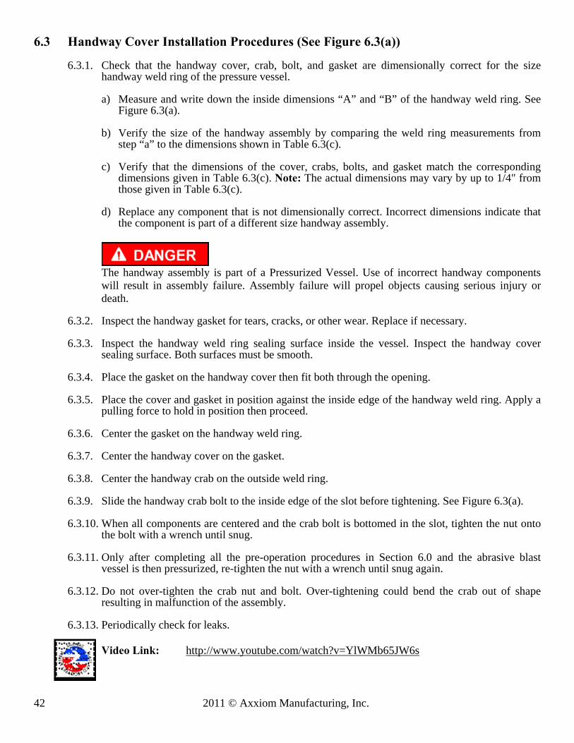
42 2011 © Axxiom Manufacturing, Inc.
6.3 Handway Cover Installation Procedures (See Figure 6.3(a))
6.3.1. Check that the handway cover, crab, bolt, and gasket are dimensionally correct for the size handway weld ring of the pressure vessel.
a) Measure and write down the inside dimensions “A” and “B” of the handway weld ring. See
Figure 6.3(a).
b) Verify the size of the handway assembly by comparing the weld ring measurements from step “a” to the dimensions shown in Table 6.3(c).
c) Verify that the dimensions of the cover, crabs, bolts, and gasket match the corresponding
dimensions given in Table 6.3(c). Note: The actual dimensions may vary by up to 1/4" from those given in Table 6.3(c).
d) Replace any component that is not dimensionally correct. Incorrect dimensions indicate that
the component is part of a different size handway assembly.
The handway assembly is part of a Pressurized Vessel. Use of incorrect handway components will result in assembly failure. Assembly failure will propel objects causing serious injury or death.
6.3.2. Inspect the handway gasket for tears, cracks, or other wear. Replace if necessary.
6.3.3. Inspect the handway weld ring sealing surface inside the vessel. Inspect the handway cover
sealing surface. Both surfaces must be smooth.
6.3.4. Place the gasket on the handway cover then fit both through the opening.
6.3.5. Place the cover and gasket in position against the inside edge of the handway weld ring. Apply a pulling force to hold in position then proceed.
6.3.6. Center the gasket on the handway weld ring.
6.3.7. Center the handway cover on the gasket.
6.3.8. Center the handway crab on the outside weld ring.
6.3.9. Slide the handway crab bolt to the inside edge of the slot before tightening. See Figure 6.3(a).
6.3.10. When all components are centered and the crab bolt is bottomed in the slot, tighten the nut onto
the bolt with a wrench until snug.
6.3.11. Only after completing all the pre-operation procedures in Section 6.0 and the abrasive blast vessel is then pressurized, re-tighten the nut with a wrench until snug again.
6.3.12. Do not over-tighten the crab nut and bolt. Over-tightening could bend the crab out of shape
resulting in malfunction of the assembly.
6.3.13. Periodically check for leaks.
Video Link: http://www.youtube.com/watch?v=YlWMb65JW6s

© 2011 Axxiom Manufacturing, Inc. 43
Figure 6.3 (a) – Handway Assembly
Figure 6.3 (b) – Handway Components
4” x 6” Handway Dimensions
Component A B
Weld Ring 4-1/2” 6-1/2” Cover (Top) 5-1/4” 7-3/16”
Handway Gasket 5-1/2” 7-1/2” Handway Crab 1-5/8” 5-1/2”
Cover (Side View) ¾” – 10UNC 4-1/2
Table 6.3 (c) – Handway Component Dimensions

44 2011 © Axxiom Manufacturing, Inc.
7.1 Filling the MINIBRS Abrasive Blast System with Abrasive
7.1.1. The MINIBRS abrasive blaster must be completely depressurized before filling can begin.
Disable the blast controls by disconnecting the twinline connections (#55) or the electric cords (for systems with electric blast controls). See Section 6.2.
Airborne particles and loud noise hazards from blowdown exhaust air can cause serious injury and loss of hearing. Wear approved eye and ear protection. Stay clear of blowdown air path. DO NOT place hands or other body parts in the blowdown air path. Make sure no personnel are in the blowdown air path. Do Not disconnect the blowdown hose (#7) from the reclaim hopper (#37).
Video Link: http://www.youtube.com/watch?v=zOvQfILu2aE
7.1.2. Connect vacuum hose to inlet connection (#44) to vacuum abrasive into the reclaim hopper (#37).
7.1.4. Open the air inlet ball valve (#1).
7.1.5. Open supply ball valve (#74) to turn ON vacuum.
7.1.6. Using the vacuum hose, vacuum a pre measured amount of abrasive into the blast vessel (#36).
7.1.7. Do Not overfill. Overfilling will cause good abrasive to carry over into the secondary cyclone
(#38) and the dust collector (#39). 7.1.8. Check reading on differential pressure gauge (#51). 7.1.8. Close supply ball valve (#74) to stop vacuum. 7.1.9. Use wand to clean filter if differential pressure gauge is greater than 6”WC. Refer to 5.22.
Video link: http://www.youtube.com/watch?v=tj-zXdfWgIk
7.0 Operating Instructions

© 2011 Axxiom Manufacturing, Inc. 45
7.2 Beginning the Blasting Operation (See Figure 7.2)
7.2.1. The MINIBRS Abrasive Blast System must be properly prepared and all operating personnel must be thoroughly trained before beginning the blast operation. Completely read and understand all sections of this manual before beginning the blast operation. See the pre-operation procedures given in Section 6.0.
7.2.2. Perform the required inspections and maintenance before beginning the blast operation. See the
instructions given in Section 8.0.
The MINIBRS abrasive blaster is a Pressurized Vessel. Propelled objects will cause serious injury or death. Depressurize vessel before performing any maintenance. See Section 6.2.
7.2.3. If Equipped, open the abrasive shutoff valve(s) (#13). See Figure 5.11.
7.2.4. Open the manual choke valve(s) (#11). Leave the choke valves completely open at all times while
blasting. Close the choke valve only for the “choke” procedure (see Section 11.3.2.). Do Not blast for long periods with the choke valve partially closed since this will cause excess wear in Thompson Valve II (#14).
7.2.5. For initial startup turn the Thompson Valve II knob (#14) counterclockwise about four turns to
partially open. The best setting for this valve differs from one situation to another; therefore it may take more than one adjustment to achieve the desired air/media mixture. Further adjustment can be made later as needed.
7.2.6. Slowly open the air inlet ball valve (#1). The ball valve is closed when the handle is perpendicular to the body. See Figure 7.2 Video link: http://www.youtube.com/watch?v=QuSXmUDvRJE
7.2.7. Slightly open the petcock valve (#3) at the bottom of the air filter (#2) to allow moisture to continually drain during the blast operation. Once each day open the petcock completely to blow out all moisture and dirt particles.
7.2.8. For initial startup back the knob of the air pressure regulator (#5) all the way out by turning the knob counterclockwise until no resistance is felt. Then turn the knob clockwise a few turns for a low initial pressure setting. Further adjustment can be made later as needed.
Video Link: http://www.youtube.com/watch?v=8CPldibHW-U
7.2.9. The following steps are for setting the required blast pressure and abrasive flow. This
determination may require several adjustments and testing of the blast flow. It is recommended that testing of the blast be made on a test piece so not to damage anything of value.

46 2011 © Axxiom Manufacturing, Inc.
7.2.10. With one hand grip the blast hose assembly (#49) and with the other hand press in the deadman safety button. To begin blasting, aim the blast nozzle at the object to be blasted, then firmly press down the deadman lever (#17). Air and blast abrasive will flow into the blast hose and out of the blast nozzle (#48). Observe the blast stream and the coating removal rate. Release the deadman lever to stop blasting. Video Link : http://www.youtube.com/watch?v=1TtSpOSRgcY
Do not aim blast nozzle towards yourself or any person. System malfunction can cause accidental start up and result in injury to personnel.
7.2.11. If necessary adjust tank pressure by turning the knob on the tank/blast pressure regulator (#5). Turn clockwise to increase pressure or counterclockwise to decrease pressure. The air pressure regulator is non-relieving therefore a reduction of tank pressure will not be evident on the gauge until blasting begins. For the most accurate setting, this adjustment should be made while blasting. The blast pressure is indicated by the pressure gauge (#4) while blasting. Note: Further tank/blast pressure adjustment may be required when actual blasting is begun.
Video Link: http://www.youtube.com/watch?v=8CPldibHW-U
7.2.12. If necessary the abrasive flow can be adjusted with the knob on the Thompson Valve II (#14).
Turn clockwise for less abrasive flow and counter-clockwise for more abrasive. Due to the length of the blast hose there will be a slight delay in control of the abrasive flow at the nozzle, therefore allow a few seconds before adjusting further. Note: If the blaster is equipped with the optional abrasive cut-off feature set the valve (or switch) to the “on” position to blast with abrasive. See Section 9.10.
7.2.13. Re-test the blast air and abrasive mixture again on a test piece to determine if further adjustment
is needed. Release the deadman lever(#17) to stop blasting.
7.2.14. If the closed cycle blasting method (blasting with simultaneous vacuum recovery) will be used the blast pressure and abrasive flow adjustments detailed in steps 7.2.9 through 7.2.13 must be made after completing the instructions given in Section 7.3.

© 2011 Axxiom Manufacturing, Inc. 47
Figure 7.1 – Typical MINIBRS Abrasive Blaster * Internal component (not shown)

48 2011 © Axxiom Manufacturing, Inc.
7.3 Closed Circuit Blasting (simultaneous blast and vacuum recovery)
7.3.1. The MINIBRS Abrasive Blast System must be properly prepared and all operating personnel must be thoroughly trained before beginning the blast operation. Completely read and understand all sections of this manual before beginning the blast operation. See the pre-operation procedures given in Section 6.0 and the initial blast operating procedures given in Section 7.2.
7.3.2. To operate in the closed cycle mode (blasting with simultaneous vacuum recovery) requires the MINIBRS blast head (#60) and a vacuum hose (#67). See Section 5.16.
7.3.3. Inspect the brushes on the MINIBRS vacuum head (#60). Replace if worn or damaged. Refer to drawing in Section 9.9. Video Link: http://www.youtube.com/watch?v=WPX90lBlaiU
7.3.4. Connect the BRS vacuum head (#60) to the nozzle holder (#48) of the blast hose assembly.
7.3.5. Connect the vacuum hose (#67) between the blast head and the reclaimer vacuum port (#44). Use the hose adapter to connect the 2” vacuum hose to the miniBRS vacuum head. See Figure 7.3.
Video Link: http://www.youtube.com/watch?v=4YFiwquSKbs
Video Link: http://www.youtube.com/watch?v=ixW0CIy1xFc
Figure 7.3 – Workhead Connections
7.3.6. Place the BRS blast head (#60) against the surface to be blasted.
7.3.7. With one hand grip the blast head assembly (#60) and with the other hand press in the deadman safety button. To begin blasting, hold the blast head against the object to be blasted, then firmly press down the deadman lever (#17). Air and blast abrasive will flow into the blast hose and out of the blast nozzle (#48). Release the deadman lever to stop blasting. Video Link: http://www.youtube.com/watch?v=1TtSpOSRgcY
Do not aim blast nozzle towards yourself or any person. System malfunction can cause accidental start up and result in injury to personnel.
7.3.8. Make necessary adjustments to the blast pressure and abrasive flow as detailed in steps 7.2.9 through 7.2.13 in Section 7.2.

© 2011 Axxiom Manufacturing, Inc. 49
7.3.9. Re-test the blast air and abrasive mixture again on a test piece to determine is further adjustment is needed. Release the deadman lever to stop blasting.
7.4 Ending the Blast Operation (See Figure 7.2)
7.4.1. Closed the vacuum supply ball valve (#74). Do not shut off vacuum while closed circuit blasting. This will cause release of dust and abrasives.
7.4.2. Close the air inlet ball valve (#1). The ball valve is open when the handle is fully turned to the position shown in Figure 7.2 (handle perpendicular to body). The handle tab will bottom against the ball valve body in the closed position.
Do not turn off the air compressor and allow the abrasive blaster air pressure to back flow through the system. Back flow will carry abrasive back into the piping contaminating the controls.
7.4.5. Completely open the petcock valve (#3) at the bottom of the air filter (#2) to allow all the accumulated moisture to be drained out. Close the petcock after draining.
7.4.3. For long periods of non-usage, remove remaining blast abrasive to prevent moisture
contamination. 7.5 Vacuum Recovery of Blast Abrasive
7.5.1. After open blasting, the used abrasives can be vacuum recovered back into the MINIBRS blast
system by following the filling procedure given in Section 7.1. DO NOT overfill blast pot 7.5.2. The used abrasive will contain dust particles that will be carried into the secondary cyclone (#38)
and the dust collector (#39). Clean filter using wand (#52) when differential pressure gauge reads higher than 6”WC. Refer to 5.22. Video Link: http://www.youtube.com/watch?v=tj-zXdfWgIk
7.5.3. Empty the cyclone dust drum (#34) and the dust collector dust bin (#32) as detailed in Section
6.1.
Abrasive blasting produces dust which may contain Silica and other toxic substances that can cause severe and permanent lung damage, cancer, and other serious diseases if inhaled. Wear OSHA approved respiratory protection when opening the dust collector and/or the dust drum. See Sections 3.8, 3.10, and OSHA 29 CFR 1910.134. Video Link: http://www.youtube.com/watch?v=8dGsSXg5I9g Video Link: http://www.youtube.com/watch?v=20ySiUj0jAg

50 2011 © Axxiom Manufacturing, Inc.
The MINIBRS abrasive blaster is a Pressurized Vessel. Propelled objects will cause serious injury or death. Depressurize vessel before performing any maintenance. See Section 6.2.
For proper operation, maintenance should be performed with the assistance of a qualified serviceman. 8.1. Blaster Pressure Vessel: The ASME Code is a standard covering materials, design, fabrication, and
installation of pressure vessels. Vessel integrity subsequent to purchase is the responsibility of the owner and/or user. At intervals required by state law and/or local authorities, the vessel should be subjected to a hydrostatic test as described in the ASME Code, Section VIII, Division 1. Do Not subject the abrasive blaster pressure vessel to a pneumatic proof test exceeding the maximum allowable working pressure. In no case should the hydrostatic test pressure exceed 1.3 times the maximum allowable working pressure (MAWP) shown on the pressure vessel nameplate. Thoroughly clean and dry the vessel before re-assembly. Moisture or debris left in vessel can cause equipment malfunction.
8.2. Blaster Pressure Vessel: Any damage to an abrasive blaster can make it unsafe. Inspect the exterior of
the abrasive blast vessel daily for corrosion, pitting, or other damage (i.e. dents, gouges or bulges). If damaged, take out of service immediately and have it inspected and/or repaired by a qualified facility. Contact Axxiom Manufacturing, Inc. for technical support.
8.3. Blaster Pressure Vessel: The interior condition of the abrasive blast vessel (#36) should be inspected
quarterly. Pitting caused by corrosion will reduce the wall thickness of the vessel. If excessive corrosion is found, have the abrasive blast vessel inspected by a qualified facility. Contact Axxiom Manufacturing, Inc. for technical support.
Check the pressure vessel internal piping for corrosion, cracks, and holes.
8.4. Popup Assembly: The popup alignment and operation is tested by the manufacturer, however vibration and creeping during shipment may cause the internal popup support piping to shift resulting in misalignment. Prior to initial usage and periodically thereafter, the popup gap and alignment should be checked. Inspect the popup as follows:
a) Depressurize the MINIBRS abrasive blaster per Section 6.2. b) Disconnect air supply hose from the crowfoot (#1). c) Inspect the popup gasket (#9) and popup head (#10) sealing surfaces for wear or deformations.
Replace either if necessary. d) Check that the popup is centered within the gasket opening. If necessary, use a pry bar as a lever
between the popup and gasket to deflect the internal support piping and shift the popup to the center of the gasket opening.
e) Check the popup gap (distance between the popup surface and the gasket). It should be between 0.625” and 0.840”. See Figure 8.1. An excessive gap is created by a vertical nipple that is too short. An excessive gap will expose the top of the vertical nipple to abrasive when the popup closes which could result in premature wear to the popup.
f) After checking the alignment and gap, pressurize the blast vessel and check the popup for air leaks. If a leak is present, repeat the above steps to isolate the problem.
Pinch point hazard. Vessel pressurization will close the popup. Keep fingers clear of the popup opening. Disconnect air supply prior to performing popup maintenance.
8.0 Maintenance and Inspection Instructions

© 2011 Axxiom Manufacturing, Inc. 51
Figure 8.1 – Standard Popup Assembly
8.6. Blast and Air Hoses: All air hoses, blast hoses, control hoses, and wires should be inspected daily for
wear, dry rotting, cracking or leakage. Repair or replace any hoses or wires that show any signs of wear, leakage or other damage. Damaged wires and/or hoses can cause system malfunctions and can result in serious injury or death to operating personnel. Blast hoses are a high wear component of the abrasive blast system. Sharp bends in the blast hose create high wear points resulting in soft spots that can rupture while blasting. Check the full length of the blast hose assembly for soft spots caused by wear. To protect against serious injury to personnel replace blast hoses with soft spots. Note: Static electricity is generated by the abrasive flow through the blast hose. To minimize chance of electric shock to operators only use static dissipating blast hose and install a grounding strap on the abrasive blaster.
Worn blast hose assemblies can rupture while blasting and the resulting abrasive blast stream can cause serious personal injury.
Static electric shock hazard. To minimize the chance of static electric shock install a grounding strap on the abrasive blaster and only use static dissipating blast hose.
8.7. Blast and Air Hoses: All air hose, blast hose, and threaded couplings have pin holes that align when connected. To prevent accidental hose disconnections safety pins must be installed through these holes. Each hose connection must also include a hose whip check that will hold the hose if there is an accidental disconnection. Connect one loop to each side of the connection and stretch out as shown in Figure 8.2 below. Check hose connections daily and replace missing or damaged pins and whip checks.
Failure to install safety pins on all air and blast hose couplings can result in hose disconnects and could result in serious injury or death.
Figure 8.2 – Hose Connection Disconnect Protection

52 2011 © Axxiom Manufacturing, Inc.
8.8. Blast and Air Hoses: All air hose, blast hose, and threaded couplings have gaskets that seal the connection. To prevent loss of air pressure and/or premature abrasive wear replace these gaskets when leaks are found. Inspect the couplings daily for leaks and wear. Replace gaskets when visible wear or leaks are found. When installing or replacing hose couplings cut the hose end square for secure fit (see Figure 8.3). To insure proper coupling connection always use fittings that are the same brand. See the drawings and part lists in Section 9.1 and 9.2.
Figure 8.3 – Hose End Fit up
8.9. Blast Nozzle: Remove the blast nozzle from the vacuum head daily and check the jacket and internal conditions. Check nozzle throat diameter. An over-sized throat diameter reduces blast efficiency. Replace the blast nozzle if worn or damaged.
8.10. Valves: Thompson Valve IIs, Automatic air valves, control valves, and deadman valves should be disassembled and inspected quarterly, or more frequently if heavily used. The Thompson Valve II cylinder should be cleaned and lubricated with an anti-seize compound. Replace parts as needed with Schmidt® original factory replacement parts furnished by an authorized Schmidt distributor. Periodically check if air is leaking from end of blast nozzle when the blast operation is off. A worn Thompson Valve II seat usually causes this. It is replaced by removing the four bolts in the base of the valve to allow disassembly. Refer to valve drawings in Sections 9.0.
Depressurize vessel before performing any maintenance. See Section 6.2. Removing the Thompson Valve II bolts with the MINIBRS blaster pressurized will result in serious injury or death.
Use of replacement components that are not Schmidt original factory replacement parts may result in equipment failure which can result in serious personal injury.
8.11. PPE: Check daily to verify that all personal protective equipment is available for each blast operator.
Check daily to verify that all personal protective equipment is in good operating condition. Consult the operating and maintenance instructions provided by the manufacturer of each PPE item. See Section 3.10 and reference OSHA 29 CFR 1910 Subpart I.
Failure to use personal protective equipment could result in serious injury or death.
8.12. Warning Decals: Check monthly to verify that all the warning decals are in position and legible. See Section 0.0 for full descriptions and locations.
Failure to maintain warning decals risks the possibility of not alerting the abrasive blaster operator to potential dangers which can result in serious injury or death. See Section 0.0.

© 2011 Axxiom Manufacturing, Inc. 53
8.13. Combo Blowdown: The blowdown hose (#7) that passes through the combo valve (#8) is a 3/4" blast hose. Abrasive carry-over can wear a hole through the wall of the hose. Replace the hose with another section of hose, but make sure that the hose does not make any tight bends anywhere between the blast pot and the cyclone because this will cause the wear to be much more rapid.
8.14. Abrasive Reclaim Hopper: The abrasive screen (#21) inside the reclaimer hopper (#37) will accumulate
trash screened from the vacuum reclaimed abrasive. The screen should be periodically checked and vacuum cleaned. It can be accessed through the access door (#33). The 2” vacuum hose attachment at the connection above the reclaim(#37) can be removed to vacuum the debris on the screen. Reattached vacuum hose when finished.
Video Link: http://www.youtube.com/watch?v=icTLHGvKgfI 8.15. Secondary cyclone: During the vacuum recovery of abrasive the depleted abrasive that is carried
through the reclaimer accumulates in the dust drum (#34). The dust drum must be emptied periodically (30-60 minutes of blasting time) Dustier conditions may require more frequent emptying. Unscrew the drum (#34) from the bottom of the cyclone (#38). The drum can then be removed so the depleted abrasive can be disposed of properly. Spare drums can be supplied to minimize shutdown time.
8.16. Dust collector: During vacuum recovery of abrasive the depleted abrasive accumulates in the bottom of the dust collector (#32) bin. The dust collector must be emptied periodically.
Abrasive blasting produces dust which may contain Silica and other toxic substances that can cause severe and permanent lung damage, cancer, and other serious diseases if inhaled. Wear OSHA approved respiratory protection when opening the dust collector and/or the dust drum. See Sections 3.8, 3.10, and OSHA 29 CFR 1910.134.
Video Link: http://www.youtube.com/watch?v=20ySiUj0jAg 8.17. Dry filter cleaning: To achieve the longest life of the dry filter it is important that they be serviced
regularly. The following methods are recommendations to assist in cleaning MINIBRS dry filters. The first three are for both paper element filters and polyester element filters. However, be aware that the washing method is for polyester element filters only.
8.17.1. Compressed air method (Filter wand) The MiniBRS is equipped with a filter cleaning wand (#52) that utilizes compressed air to blow off the fine dust that have accumulated on the exterior of the filter cartridge (#30). To clean the filter, make sure that the vacuum system is turned off by closing the eductor ball valve (#74). Loosen the wand compression fitting (#53). Open the cleaning wand ball valve (#28). The wand will start flushing the filter. Move the wand (#52) up and down while rotating both directions. Video Link: http://www.youtube.com/watch?v=tj-zXdfWgIk
8.17.2. Vacuum method An alternate cleaning method to utilize is vacuuming. A commercial duty vacuum cleaner is recommended, but a common household type may also be used. Vacuum the exterior (outside diameter) surface of the filter. This procedure will remove the majority of the large particles and surface contaminants that have accumulated and may be sufficient for the first cleaning of the filter. This step should also be performed prior to progressing to any subsequent cleaning method.
54 2011 © Axxiom Manufacturing, Inc.
8.17.3. Washing method (polyester element filter only) The washing process is for polyester element filters only. The final cleaning process may be necessary to reduce the static pressure to an acceptable level when the filter has fine particles that have become imbedded in the filter element. For this procedure a mild low suds detergent should be used with clean warm water. Soak the filter for 5-10 minutes, and then gently agitate the filter for several minutes. The filter should then be thoroughly rinsed with clean water to remove the detergent. It may require a second or third washing to obtain satisfactory filtration. However, the dirt holding capacity of the filter decreases after each washing.
Critical: Do not attempt to wash dry filters with paper elements, this will render them useless. If you are not certain of the type of element seek assistance. Note: Polyester element filters can be washed and reused under proper conditions. However, Schmidt has no control over the washing process and cannot guarantee that it has been performed properly and effectively, therefore normal warranty does not apply to filters that have been washed.
8.17.4. Inspection (Not applicable for wand cleaning)
A simple method of inspection is to use a light bulb or flashlight. Light passing through the filter will reveal fatigued paper or dirt accumulations. Inspection should also include the end plates to check for possible damages during handling. Inspect for damage that could allow contaminated air to bypass the filter element. Remove filter to allow thorough filter inspection.
8.18. Pneumatic Vacuum System: The vacuum system vacuum pump requires no maintenance. The air hoses
leading to supply ball valve (#74) should be inspected daily for wear, dry rotting, cracking or leakage. Repair or replace hoses that show any signs of wear, leakage or other damage. Damaged hoses can cause vacuum system malfunctions and can result in serious injury or death to operating personnel.
8.19. Handway Assembly: Refer to Section 6.3 for installation and inspection procedures.

© 2011 Axxiom Manufacturing, Inc. 55
8.20 Maintenance Schedules Quick Reference Charts
MINIBRS ABRASIVE BLASTER MAINTENANCE SCHEDULE
ITEM MAINTENANCE
REQUIRED DAILY WEEKLY MONTHLY QUARTERLY
Blaster Vessel
Hydrostatic Test See Section 8.1
As required by state law and/or local authorities
Blaster Vessel
Check for exterior damage (corrosion, dents, bulges).
See Section 8.2 X
Blaster Vessel
Check for interior damage (corrosion / pitting).
See Section 8.3 X
Popup Check sealing surfaces, alignment and gasket to
popup gap. See Section 8.4
X
Blast & Air Hoses
Check hoses for soft spots, wear, cracks, or air leaks
See Section 8.6 X
Remote Control Hoses
Check hoses for soft spots, wear, cracks, or air leaks
See Section 8.6 X
Remote Control Wires
Check wiring for bare spots, fraying, or cracks
See Section 8.6 X
Blast & Air Hose
Couplings
Check for safety pins and whip checks See Section 8.7
X
Hose Coupling Gaskets
Check for leaky air and blast hose coupling gasketsSee Section 8.8
X
Blast Nozzle Check blast nozzle threads and jacket and for air leaks
See Section 8.9 X
Valves Disassemble, inspect, and lubricate.
See Section 8.10 X
Personal Protective Equipment
Check condition of all personal protective equipment See Section 3.10 and
8.11 X
Warning Decals
Check the condition of warning decals. See Sections 0.0 and 8.12
X
Combo Blowdown
Check condition of Blowdown hose See Section 8.13
X
Reclaimer Screen
Clean trash from Abrasive screen See Section 8.14
X
Cyclone Dust Drum
Empty secondary cyclone dust drum See Section 8.15
X
Dust Collector Dust Bin
Drain dust from dust collector See Section 8.16
X
Dust Collector Air Filters
Clean and inspect dust collector filters See Section 8.17
X
Vacuum System
Check hoses for soft spots, wear, cracks, or air leaksSee Section 8.18
X
Handway Assembly
Check condition of gasket and sealing surfaces See Sections 8.19 and 6.3.
X

56 2011 © Axxiom Manufacturing, Inc.
THIS PAGE INTENTIONALLY BLANK

© 2011 Axxiom Manufacturing, Inc. 57
The following pages contain drawings representing typical blast
control systems and components. Determine the type of control
system the abrasive blast system is equipped with (pneumatic or
electric controls) then reference the appropriate drawing and
parts list to determine the required parts. To insure the proper
operation of the blast system only use Schmidt® original factory
replacement parts furnished by an authorized Schmidt
distributor. See Section 1.37 and Section 12.2.12.
9.0 Drawings and Parts Lists

58 2011 © Axxiom Manufacturing, Inc.
9.1(a) MINIBRS Abrasive Blaster

© 2011 Axxiom Manufacturing, Inc. 59
9.1(c) MINIBRS Abrasive Blast System Parts List

60 2011 © Axxiom Manufacturing, Inc.
9.1(d) MiniBRS Workhead Parts
(See Section 9.9 for Workhead optional parts list)
9.2 MINIBRS Abrasive Blaster Pneumatic Schematic

© 2011 Axxiom Manufacturing, Inc. 61
9.3 Electrical Diagrams (Applicable to electric controls)
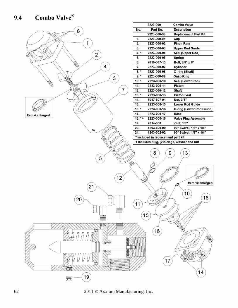
62 2011 © Axxiom Manufacturing, Inc.
9.4 Combo Valve®
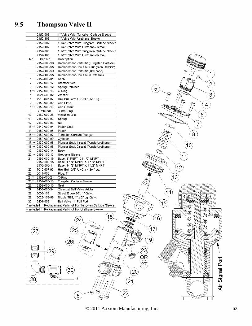
© 2011 Axxiom Manufacturing, Inc. 63
9.5 Thompson Valve II

64 2011 © Axxiom Manufacturing, Inc.
9.6 Control Valves (Applicable to electric controls)

© 2011 Axxiom Manufacturing, Inc. 65
9.7 Automatic Air Valve (normally closed)

66 2011 © Axxiom Manufacturing, Inc.
9.8(a) G2 Pneumatic Deadman
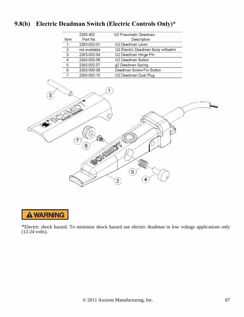
© 2011 Axxiom Manufacturing, Inc. 67
9.8(b) Electric Deadman Switch (Electric Controls Only)*
*Electric shock hazard. To minimize shock hazard use electric deadman in low voltage applications only (12-24 volts).

68 2011 © Axxiom Manufacturing, Inc.
9.9 Vacuum Head Parts Video: http://www.youtube.com/watch?v=WPX90lBlaiU
9.10 Remote Abrasive Cut-off (Optional If Equipped)

© 2011 Axxiom Manufacturing, Inc. 69
10.1 Recommended Spare Parts List
ITEM QTY PART # DESCRIPTION 12 1 2123-006-02 1 1/4" & 1 1/2" Auto Air Valve Diaphragm 12 2 2123-006-99 1 1/4" & 1 1/2" Auto Air Valve Replacement Part Kit 12 1 2123-106 1 1/2" Auto Air Valve 12 2 2123-106-24 1 1/4" & 1 1/2" Auto Air Valve Spring 12 2 2014-300 Breather Vent, 1/8” 66 2 2013-402 Dust Eliminator, 1/4" (ELECTRIC CONTROLS ONLY) 14 1 2152-000-03 Thompson Valve II Spring 14 1 2152-000-14 Thompson Valve II Body with pin 14 1 2152-000-11 Thompson Valve II Base 14 1 2152-000-98 Thompson Valve II Replacement Parts Soft Kit
1,11,74 1 2401-506 1 “Ball Valve (see Section 9) 18 1 7000-000-06 Handway Gasket, 4” x 6” 70 4 4214-999 Hose Coupling Gasket
N/A 4 4205-106-99 1” Air Hose Swivel Gasket 71 8 7119-002 Safety Pin, Air/Blast Hose Coupling 17 1 2263-002 G2 Pneumatic Deadman Valve 16 1 2263-002-99 G2 Pneumatic Deadman Replacement Kit 17 1 2263-400 Electric Deadman Valve (ELECTRIC CONTROLS) 8 1 2223-999 Combo Valve replacement parts kit 8 1 2223-000-18 Combo Valve plug assembly 7 1 4115-005 Blowdown Hose Assy, 3/4" x 18” 30 2 8031-000-01 MiniBRS Dust Collector Filter (Spun Bond Poly) 48 1 8033-000-09 MiniBRS Workhead Blast Nozzle #3 (Standard) 48 8033-000-10 MiniBRS Workhead Blast Nozzle #4 (Also Available) 60 1 8033-000-13 MiniBRS Workhead Rubber Liner 60 2 8033-000-14 MiniBRS Workhead Brush Retainer 60 4 8033-000-15 MiniBRS Workhead Straight Brush (Standard) 60 8033-000-16 MiniBRS Workhead Outside Corner Brush (Also Available) 60 8033-000-18 MiniBRS Workhead Inside Corner Brush (Also Available)
10.2 Instructional Video Links (Requires Internet Connection) DESCRIPTION & URL Microsoft Video Tag
Connecting vacuum hose to blast workhead http://www.youtube.com/watch?v=4YFiwquSKbs
Disassembly & assembly of blast workhead http://www.youtube.com/watch?v=WPX90lBlaiU
Eductor vacuum ON/OFF
http://www.youtube.com/watch?v=Nrz9TZqoYfw
Removing access cover and vacuum cleaning screen.
http://www.youtube.com/watch?v=icTLHGvKgfI
10.0 Recommended Spare Parts List & Video List

70 2011 © Axxiom Manufacturing, Inc.
10.2 Instructional Video Links (Requires Internet Connection) cont.
Removing and reinstalling cyclone bin
http://www.youtube.com/watch?v=8dGsSXg5I9g
Removing dust collector bin and removing filter
http://www.youtube.com/watch?v=20ySiUj0jAg
Wand cleaning of filter
http://www.youtube.com/watch?v=tj‐zXdfWgIk
Connect twinline to Combo Valve
http://www.youtube.com/watch?v=oL2EGYQQkPo
Removing and inspecting 4x6 handway
http://www.youtube.com/watch?v=YlWMb65JW6s
Vacuum loading MiniBRS (Sound)
http://www.youtube.com/watch?v=zOvQfILu2aE
Closed circuit blasting with MiniBRS workhead(Sound)
http://www.youtube.com/watch?v=1TtSpOSRgcY
Operation of inlet ball valve
http://www.youtube.com/watch?v=QuSXmUDvRJE
Blast pressure regulator operation
http://www.youtube.com/watch?v=8CPldibHW‐U
Connecting the 2" vacuum hose to reclaimer inlet
http://www.youtube.com/watch?v=ixW0CIy1xFc

© 2011 Axxiom Manufacturing, Inc. 71
This section lists probable causes of problems that may occur during operation of the abrasive blaster. Not all of the “probable causes” may apply to your particular abrasive blaster. The probable cause may not apply because of the control type and accessories on the abrasive blaster. Refer to Figure 11.1 and the drawings in Section 9.0.
The MINIBRS abrasive blaster is a Pressurized Vessel. Propelled objects will cause serious injury or death. Depressurize vessel before performing any maintenance. See Section 6.2. 11.1 Malfunction With Deadman Lever In The “Off” Position
11.1.1. Blast air stops but abrasive will not shut off (1) Trash stuck between plunger and seat in Thompson Valve II (#14).
(2) Defective valve plunger in Thompson Valve II (#14). (3) Defective sleeve in Thompson Valve II (#14). (4) Blocked air hose to Thompson Valve II (#14). (5) Defective spring in Thompson Valve II (#14) (check length of spring).
(6) Thompson Valve II cap (or spring retainer) not screwed all the way down (hand tighten only). 11.1.2. Abrasive stops but blast air will not shut off (1) Defective spring in automatic air valve (#12).
(2) Defective seat in automatic air valve (#12). (3) Blocked air hose to automatic air valve (#12). (4) Defective o-ring in automatic air valve (#12) (around shaft).
11.1.3. Both blast air and abrasive will not shut off
(1) Control lines to deadman valve (#17) are crossed. (2) Non-Schmidt deadman (#17) has been installed. (3) Control valve (#15) stuck in the “ON” position. (4) Blocked control lines.
(5) Defective deadman valve (#17). Pneumatic deadman cartridge plunger stuck in the “ON” position (down). Cartridge plunger is visible below deadman handle.
11.1.4. Blast outlet turns on accidentally
(1) The deadman lever (#17) is worn out. (2) The safety button on the deadman is missing. See drawings in Section 9.8. (3) A bleeder type deadman valve has been installed. A bleeder type deadman valve is not safe
because a particle of dirt from the air hose can plug the bleed hole and cause the blast outlet to turn on. See Warnings and Rules for Safer Operation in Section 1.0.
(4) Defective electric deadman switch or electric wiring (check for an electric short).
11.0 Troubleshooting

72 2011 © Axxiom Manufacturing, Inc.
Figure 11.1 – Typical MINIBRS Abrasive Blast System
11.2 Malfunction With Deadman Lever In The “On” Position
11.2.1. Air blasts with no abrasive
(1) Check abrasive level in the blast vessel even if one outlet continues to blast normally. (2) Blocked control hose to Thompson Valve II (#14). (3) Thompson Valve II plunger stuck in closed position. (4) Trash plugging opening from tank to Thompson Valve II (#14). See Section 11.3. (5) Insufficient air pressure to open Thompson Valve II (fully open requires 80 psig). (6) Abrasive flow problems. See Section 11.3. (7) Defective Thompson Valve II piston seal (air will leak from breather vents). (8) Blast vessel leaks causes reverse differential pressure slowing abrasive flow.
11.2.2. Abrasive choking out of blast hose with low blast air pressure.
(1) Thompson Valve II abrasive adjustment knob (#14) is open too far. (2) Control hose to automatic air valve (#14) is blocked. (3) Choke valve (#11) is partially closed.
(4) Low air compressor output cfm (unit may cycle on and off). See Section 3.0. (5) Blocked automatic air valve breather vent (#12).
11.2.3. Reduced Pressure At The Nozzle (with or without abrasive flow)
(1) Low air compressor output cfm. See Section 3.0 for air requirements. (2) Air hose too small. (3) Thompson Valve II abrasive adjustment knob (#14) is open too far. (4) Check for leaks in blast vessel or control piping. (5) Choke valve (#11) is partially closed. (6) Trash may be partially plugging the nozzle orifice (#48). (7) Blocked automatic air valve breather vent (#12).

© 2011 Axxiom Manufacturing, Inc. 73
11.2.4. Blast is slow to turn on or will not turn on when deadman lever is pressed down.
(1) Check quick couplings (#55) on control hoses to see if they are connected properly. (2) Control valve (#15) stuck in exhaust position. (3) 1/4" strainer (#3) blocked. (4) Control hoses blocked. (5) Cartridge in deadman valve (#17) is blocked. (6) Low air compressor output cfm (unit may cycle on and off). See Section 3.0. (7) Air leaks in control hose from the deadman valve (#17) to control valve (#15). (8) Trash blocking nozzle orifice.
(9) Blocked automatic air valve breather vent (#12).
11.3 Notes on Abrasive Flow Problems
11.3.1. Thompson Valve II operation If abrasive flow is a problem, remember; the Thompson Valve II only opens and closes. The total travel to full open is approximately 3/4 of an inch. This can be quickly checked with the adjustment knob on the abrasive valve. For this procedure close the choke valve (#11) and the abrasive shut-off valve (#13) to prevent blasting. This test is to verify that the Thompson Valve II is opening. With the deadman off, screw the Thompson Valve II knob down until it stops. Notice that the knob turns easily when the deadman is off. Next, back the knob out 3/4 of an inch or slightly less, then press the deadman lever down to open the Thompson Valve II. The knob should get tight or more difficult to turn because the valve has opened against the adjustment. This guarantees that the valve is fully open. If the material will not flow with the valve fully open, you have an abrasive flow problem, not a problem with the Thompson Valve II. The abrasive may be wet, or there may be trash blocking the opening. Try choking the blast outlet to clear the opening. Proceed to step 11.3.2. If the knob does not get tighter during this test troubleshoot the controls and the Thompson Valve II piston seal.
Do Not hammer on any part of the pressure vessel to improve abrasive flow. This will cause cracks that may lead to pressure vessel rupture.
11.3.2. Choking the blast outlet
The choke valve (#11) is used to clear any trash that may get into the blast vessel and block the Thompson Valve II orifice. When trash (paint chip, cigarette butt, etc.) blocks the Thompson Valve II orifice, the procedure is to fully open the Thompson Valve II knob, then press down the deadman lever (#17) to begin blasting. While blasting, have an assistant close the choke valve completely for about one second. This creates differential pressure at the Thompson Valve II (high pressure above; low pressure below). The higher pressure from the blast vessel should be enough to loosen the trash blocking the Thompson Valve II orifice and blast it through the blast nozzle (#48). To prevent excess wear of the Thompson Valve II keep the choke valve fully open during normal blasting. If the blaster is equipped with the abrasive cut-off feature set the valve (or switch) to the on-position for the choke procedure. See Section 9.10. Note: The Thompson Valve II has a cleanout port to use for this procedure. See the Thompson Valve II drawing in Section 9.5 (Item 27).
11.3.3. Blast control hoses
Remember, the blaster controls and valves are normally closed. Therefore, the control hoses are depressurized to turn the blast off and pressurized to turn the blast on. If a needle gauge is available, it is the quickest way to check to see if there is pressure or not. If no needle gauge is available, disconnect each control hose fitting one at a time until the problem is located.

74 2011 © Axxiom Manufacturing, Inc.
12.1 Warranty This following section is to be used as a guide in determining warranty policies and procedures for SCHMIDT® products. It is to be used in determining whether a warranty is justified and as a procedural guide in completing a SCHMIDT warranty claim.
12.2 Warranty Policy
1. All SCHMIDT products are guaranteed to be free of defects in material and workmanship at time of shipment. Axxiom Manufacturing, Inc. warrants its products against defects in material and workmanship under normal and proper use for a period of ninety (90) days from the date of delivery. Such warranty is extended only to the buyer who purchases the equipment directly from Axxiom Manufacturing, Inc. or its authorized distributors. This warranty does not include expendable parts such as, but not limited to, hoses, nozzles, and seals.
2. The obligation under this warranty is strictly limited to the replacement or repair, at Axxiom’s
option, of machines and does not include the cost of transportation, loss of operating time, or normal maintenance services. Axxiom Manufacturing, Inc. shall have no liability for labor, consequential damages, freight or special charges.
3. This warranty does not apply to failure occurring due to abuse, misuse, negligence, corrosion,
erosion, normal wear and tear, alterations or modifications made to the machine without express written consent of Axxiom Manufacturing, Inc.
4. Warranty requests must be submitted in writing within thirty (30) days after failure. 5. Written authorization to return merchandise under warranty must first be obtained from Axxiom
Manufacturing, Inc. In no case is merchandise to be returned to Axxiom for credit without authorization. At the time of authorization, Axxiom will issue a return authorization number that must be included on all packages and correspondence. Any material returned without prior authorization will remain the property of the sender and Axxiom will not be responsible for it.
6. All returns must be shipped prepaid freight. All returns may be exchanged for other equipment or
parts of equal dollar value. If goods are not exchanged, they are subject to a 20% restocking charge. Any cost incurred by Axxiom Manufacturing, Inc. to restore such goods to first class condition will be charged to the customer.
7. Axxiom Manufacturing, Inc. reserves the right to inspect and make the final decision on any
merchandise returned under warranty.
8. Axxiom Manufacturing, Inc. offers no warranty with respect to accessories, including but not limited to, engines, motors, batteries, tires and any other parts not manufactured by Axxiom Manufacturing, Inc., but which the original manufacturer warrants.
9. Axxiom Manufacturing, Inc. reserves the right to make product changes or improvements without
prior notice and without imposing any obligation upon itself to install the same on its products previously sold.
12.0 Warranty and Reference Information

© 2011 Axxiom Manufacturing, Inc. 75
10. The above warranty conditions can only be altered by Axxiom Manufacturing, Inc. Axxiom must confirm alterations in writing for each specific transaction.
11. Axxiom Manufacturing, Inc. reserves the right to establish specific warranty terms for used or demo
machines on an individual transaction basis. Invoices covering such merchandise will clearly state the provisions of the applicable warranty for each specific transaction.
12. USE OF NON-ORIGINAL SCHMIDT® FACTORY REPLACEMENT PARTS ON ANY
SCHMIDT EQUIPMENT VOIDS ALL WARRANTIES.
13. AXXIOM MANUFACTURING, INC. DOES NOT AUTHORIZE ANY PERSON, REPRESENTATIVE OR SERVICE OR SALES ORGANIZATION TO MAKE ANY OTHER WARRANTY OR TO ASSUME ON BEHALF OF AXXIOM MANUFACTURING, INC. ANY LIABILITY IN CONNECTION WITH THE SALE OF OUR PRODUCTS OTHER THAN THOSE CONTAINED HEREIN.
14. UNDER NO CIRCUMSTANCES SHALL AXXIOM MANUFACTURING, INC. BE LIABLE TO
CUSTOMER OR ANY OTHER PERSON FOR ANY DIRECT, INCIDENTAL, OR CONSEQUENTIAL DAMAGES RESULTING FROM THE USE OF THE PRODUCT OR ARISING OUT OF ANY BREACH OF ANY WARRANTY OR FOR ANY SPECIAL OR CONSEQUENTIAL DAMAGES OF ANY CHARACTER, INCLUDING WITHOUT LIMITATIONS, DAMAGES FOR ANY LOSS OF GOODWILL, WORK STOPPAGE, OR ANY AND ALL OTHER COMMERCIAL DAMAGES OR LOSSES.
15. AXXIOM MANUFACTURING, INC. MAKES NO OTHER WARRANTIES, EXPRESSED OR
IMPLIED, INCLUDING, BUT NOT LIMITED TO, THE IMPLIED WARRANTIES OF MERCHANTABILITY AND FITNESS FOR A PARTICULAR PURPOSE WITH RESPECT TO THE SCHMIDT PRODUCTS SOLD PURSUANT THERETO.
12.3 Trademarks, Patents, and Proprietary Statements
Schmidt, the Schmidt S logo, Thompson Valve II, and ComboValve are registered trademarks owned by Axxiom Manufacturing, Inc. Use of the Schmidt, the Schmidt S logo, Thompson Valve II, and Combo Valve trademarks without the written consent of Axxiom Manufacturing is strictly prohibited. Products manufactured and marketed by Axxiom Manufacturing, Inc. are protected by patents issued or pending in the United States and other countries. The text, diagrams, and drawings contained in this manual are proprietary information intended solely for instruction in the operation of the specified equipment. Use of any text, diagrams, or drawings contained in this manual for any reason other than its intended purpose without the written consent of Axxiom Manufacturing, Inc. is strictly prohibited.
76 2011 © Axxiom Manufacturing, Inc.
12.4 Safety Information Sources
Axxiom Manufacturing, Inc This equipment and all Schmidt® equipment are manufactured exclusively by Axxiom Manufacturing, Inc. If any operational or safety related questions arise relating to this equipment contact Axxiom Manufacturing, Inc. Phone: 1-800-231-2085 Website: www.axxiommfg.com Axxiom Manufacturing, Inc. 11927 South Highway 6 Fresno, Texas 77459 Occupational Safety and Health Administration (OSHA) establishes and enforces regulations regarding safety practices in the workplace including the abrasive blasting industry. Any questions, reporting of work related injuries, or reporting of unsafe work practices can be made to the following contact information. Answers to most any safety related questions can be found at the OSHA website shown below. Phone: 1-800-321-6742 Website: www.osha.gov
U.S. Department of Labor
Occupational Safety and Health Administration 200 Constitution Avenue Washington D.C. 20210
National Institute of Occupational Safety and Health (NIOSH) is a federal agency responsible for conducting research and recommendations for the prevention of work related injuries and sickness. Phone: 1-800-356-4674 Website: www.cdc.gov/niosh National Institute of Occupational Safety and Health Hubert H. Humphrey Bldg. 200 Independence Avenue, SW Room 715H Washington, DC 20201 American National Standards Institute (ANSI) coordinates the development and use of voluntary consensus standards including safety standards. Phone: 1-202-293-8020 Website: www.ansi.org American National Standards Institute 1819 L Street, NW 6th Floor Washington, DC 20036
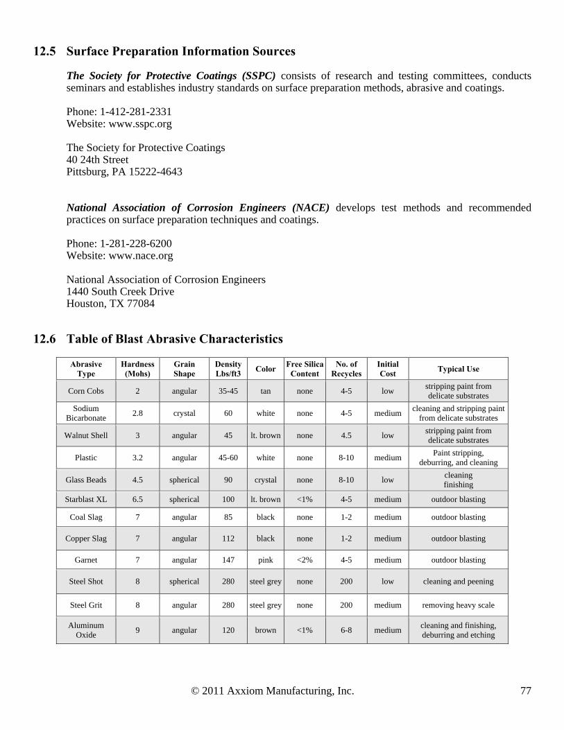
© 2011 Axxiom Manufacturing, Inc. 77
12.5 Surface Preparation Information Sources The Society for Protective Coatings (SSPC) consists of research and testing committees, conducts seminars and establishes industry standards on surface preparation methods, abrasive and coatings. Phone: 1-412-281-2331 Website: www.sspc.org The Society for Protective Coatings 40 24th Street Pittsburg, PA 15222-4643 National Association of Corrosion Engineers (NACE) develops test methods and recommended practices on surface preparation techniques and coatings. Phone: 1-281-228-6200 Website: www.nace.org National Association of Corrosion Engineers 1440 South Creek Drive Houston, TX 77084
12.6 Table of Blast Abrasive Characteristics
Abrasive Type
Hardness (Mohs)
Grain Shape
Density Lbs/ft3
Color Free Silica
Content No. of
Recycles Initial Cost
Typical Use
Corn Cobs 2 angular 35-45 tan none 4-5 low stripping paint from delicate substrates
Sodium Bicarbonate
2.8 crystal 60 white none 4-5 medium cleaning and stripping paint
from delicate substrates
Walnut Shell 3 angular 45 lt. brown none 4.5 low stripping paint from delicate substrates
Plastic 3.2 angular 45-60 white none 8-10 medium Paint stripping,
deburring, and cleaning
Glass Beads 4.5 spherical 90 crystal none 8-10 low cleaning finishing
Starblast XL 6.5 spherical 100 lt. brown <1% 4-5 medium outdoor blasting
Coal Slag 7 angular 85 black none 1-2 medium outdoor blasting
Copper Slag 7 angular 112 black none 1-2 medium outdoor blasting
Garnet 7 angular 147 pink <2% 4-5 medium outdoor blasting
Steel Shot 8 spherical 280 steel grey none 200 low cleaning and peening
Steel Grit 8 angular 280 steel grey none 200 medium removing heavy scale
Aluminum Oxide
9 angular 120 brown <1% 6-8 medium cleaning and finishing, deburring and etching

78 2011 © Axxiom Manufacturing, Inc.
13.1 Table 1 Approximate Air Consumption (cfm) Per Blast Nozzle NOZZLE PRESSURE
NOZZLE SIZE
60 psi
70 psi 80 psi 90 psi 100 psi
120 psi
140 psi
No.2 1/8"
14
16 18 20 22
26
30
No.3 3/16"
32
36 41 45 49
58
66
No.4 1/4"
57
65 72 80 90
105
121
No.5 5/16"
90
101 113 125 140
160
185
No.6 3/8"
126
145 163 182 200
235
270
No.7 7/16"
170
193 215 240 270
315
360
No.8 1/2"
230
260 290 320 350
410
470
No.10 5/8"
360
406 454 500 550
640
740
No.12 3/4"
518
585 652 720 790
925
1060
13.2 Table 2 Abrasive Consumption (lbs. per hour) Per Blast Nozzle
NOZZLE PRESSURE
NOZZLE SIZE
60 psi
70 psi 80 psi 90 psi 100 psi
120 psi
140 psi
No.2 1/8"
90
105 115 130 140
165
190
No 3 3/16"
205
230 260 290 320
375
430
No.4 1/4"
365
420 460 500 560
660
760
No.5 5/16"
575
650 725 825 900
1050
1200
No.6 3/8"
840
945 1050 1155 1260
1475
1700
No.7 7/16"
1150
1300 1450 1600 1750
2050
2350
No.8 1/2"
1460
1660 1850 2000 2250
2650
3000
No.10 5/8"
2290
2600 2900 3125 3520
4100
4750
No.12 3/4"
3300
3750 4180 4500 5060
5950
6800
13.3 Table 3 Hose Selection Guide (blasting @ 100 Psi)
NOZZLE SIZE
No.4 1/4" No.5 5/16" No.6 3/8" No.7 7/16"
No.8 1/2"
CFM @ 100psi
90 140 200 270
350
AIR HOSE
1 1/4" 1 1/4" 1 1/2" 1 1/2"
2"
BLAST HOSE
1" 1 1/4" 1 1/4" 1 1/2"
1 1/2"
ABRASIVE ( lbs per hr)
560 900 1260 1750
2250
13.4 Additional Information on Blasting Productivity Air volume and pressure are very important. The blasting production rate will increase with higher blasting pressures and decrease with lower blasting pressures. The National Association of Corrosion Engineers’ data suggests that for each 1 psi reduction in nozzle pressure, there is a 1.5% production loss. Pressure drop through a Schmidt® blast unit is normally less than 1 psi, while blast units manufactured by some of our competitors have pressure losses as high as 12 psi resulting in an 18% loss of production. Air pressure loss can also be avoided by using the shortest possible hose of adequate size. The inside diameter of both the blast hose (other than whip hose) and the air hose should be approximately three times the diameter of the orifice in the blast nozzle.
Standard Schmidt blast units are rated for a maximum pressure of 125 psi although high pressure units rated for 150 psi are available on request.
13.0 Blasting Data