Edited 2006 MATTER SOLIDS – LIQUIDS - GASES Nancy Fredrickson 2003.

Mini AERCam for In-Space Inspection Dr. Steven E. Fredrickson
Abstract: The NASA Johnson Space Center Engineering Directorate has developed the Miniature Autonomous Extravehicular Robotic Camera (Mini AERCam) as a free-flying, robotic inspection vehicle intended for future external inspection and remote viewing of human spacecraft. The Mini AERCam technology demonstration unit has been successfully integrated into the approximate form and function of a nanosatellite flight system by leveraging the success of AERCam Sprint flight system and related free-flyer technology development. The Mini AERCam free flyer can be operated via remote piloting from a control station supporting teleoperation and supervised autonomous commanding, with functions such as automatic stationkeeping, point-to-point maneuvering, and automatic docking. Free-flyer testing has been conducted on an air-bearing table and in a six degree-of-freedom closed-loop orbital simulation, and enhancements have been made to provide additional capabilities for future space-based inspection. This presentation will provide a technical overview of the Mini AERCam development, including strategies for spacecraft integration.
https://ntrs.nasa.gov/search.jsp?R=20120002583 2019-03-19T09:02:16+00:00Z
Mini AERCam for In-Space Inspection
29 February 2012
Dr. Steven E. Fredrickson
NASA JSC ER6
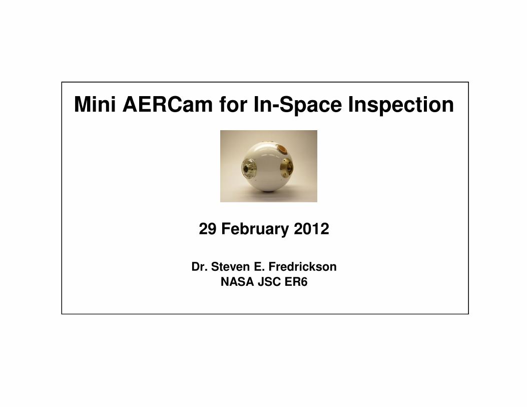
Outline
• Motivation– Historical need for better inspection and remove viewing
– Future vision
• AERCam overview– AERCam Sprint
– Mini AERCam Technology Development
– Flight concepts for Shuttle and ISS
Page 2February 2012
– Flight concepts for Shuttle and ISS
• Flight Infusion Strategy

Historical Examples of Need for Inspection (1 of 2)
• Historical examples of problems NASA would have wanted to learn about or inspect sooner (if inspection capability existed)
That the launch vehicle shroud had not separated from the Agena docking adapter, prior to the launch of Gemini 9 that was supposed to dock with it (July 1966)
The cause for Skylab’s second solar array not deploying (the first one was lost at launch) (May 1973)
Page 3February 2012
The extent of the damage to the Apollo 13 Service Module during the Apollo 13 mission (April 1970)
STS 51D ET door not sealed properly due to rolled thermal barrier wedged between the door and the door frame (April 1985)
Historical Examples of Need for Inspection (2 of 2)
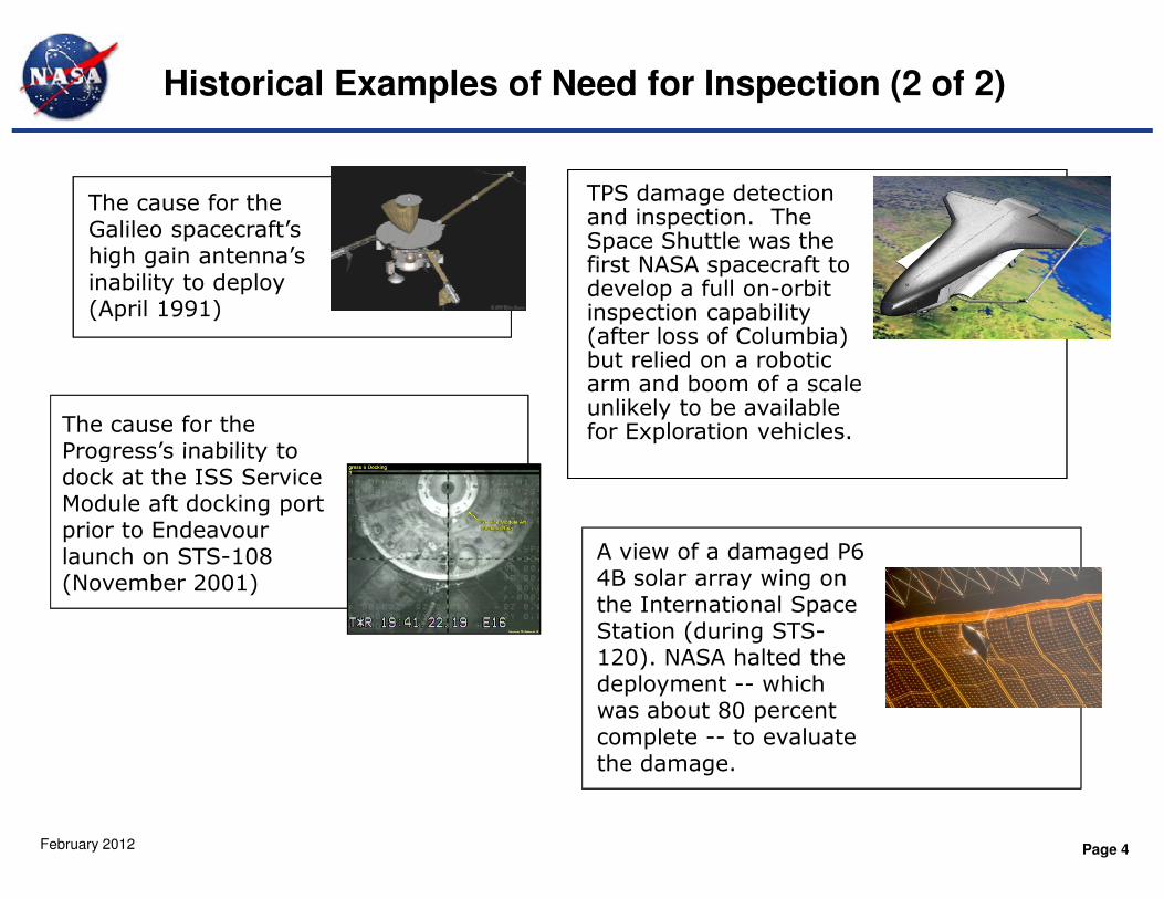
The cause for the Galileo spacecraft’s high gain antenna’s inability to deploy (April 1991)
The cause for the Progress’s inability to
TPS damage detection and inspection. The Space Shuttle was the first NASA spacecraft to develop a full on-orbit inspection capability (after loss of Columbia) but relied on a robotic arm and boom of a scale unlikely to be available for Exploration vehicles.
Page 4February 2012
Progress’s inability to dock at the ISS Service Module aft docking port prior to Endeavour launch on STS-108 (November 2001)
A view of a damaged P6 4B solar array wing on the International Space Station (during STS-120). NASA halted the deployment -- which was about 80 percent complete -- to evaluate the damage.
AERCam Vision for NASA
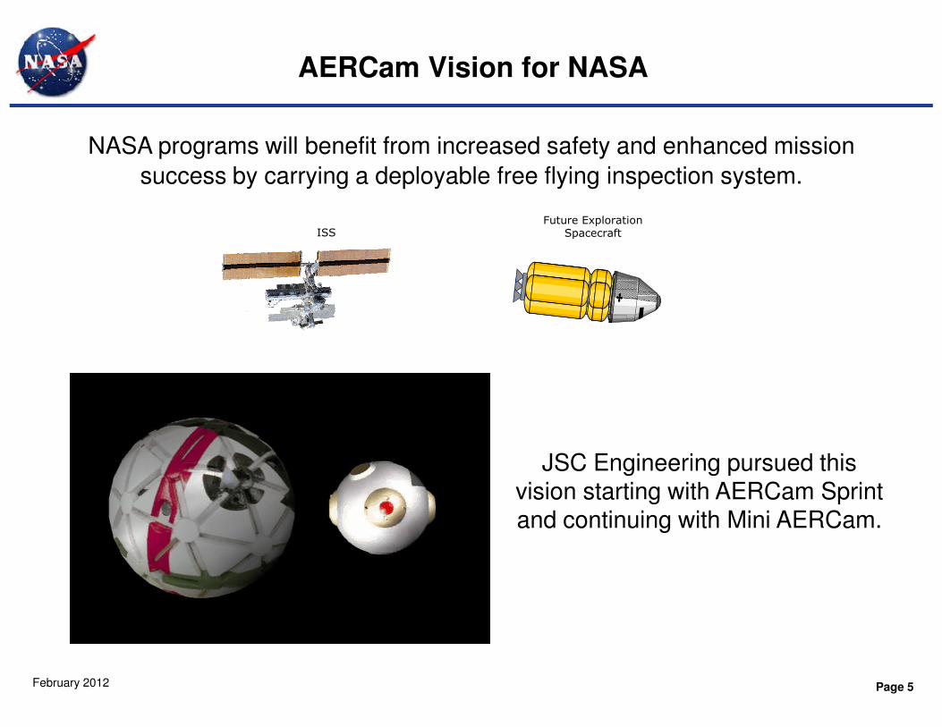
NASA programs will benefit from increased safety and enhanced mission
success by carrying a deployable free flying inspection system.
Future Exploration SpacecraftISS
Page 5February 2012
JSC Engineering pursued this vision starting with AERCam Sprint and continuing with Mini AERCam.

Potential MPCV and Exploration Applications
• Anytime external inspection of spacecraft surfaces
– Anomaly resolution aid for all mission phases: LEO, Docked at ISS (for ISS missions), Cis-Lunar cruise, Lunar orbit, Earth return
• External view of MPCV CM/SM separation or other dynamic events
• Inspect TPS after SM separation
– Even if committed to entry, choose entry mode if TPS damage is seen and the entry profile can reduce heating profile in that area
• Engage public with in-space views of spacecraft otherwise difficult
Page 6February 2012
• Engage public with in-space views of spacecraft otherwise difficult or impossible to obtain
– E.g. framing spacecraft with earth or moon in scene

AERCam History
1995 1996 1997 1998 1999 2000 2001 2002 2003 2004 2005 2006
AERCam Sprint
AERCam Technology
Mini AERCam Flight System Ground
Prototype
Mini AERCam for
Shuttle Inspection
Over 10 years of development history at JSC
ISS New Start
Relative GPS for
Page 7February 2012
Technology Demonstration
InspectionGPS for XSS
Flight test of protoflight unit on STS-87 in 1997
Testbed for advanced autonomous technologies
Ground demonstration of flight-like integrated design
Flight system development for Shuttle Inspection

AERCam Sprint on STS-87
• Free flying camera
• Flight tested in December 1997 on STS-87
• Released during EVA by Winston Scott
• Remotely piloted by Steve
Lindsey from the Orbiter
aft cockpit
Page 8February 2012
• Flown for over an hour
around the Payload Bay
• Sprint provided color video
• 14-inch diameter, 35 pounds
• Demonstrated capabilities included
automatic attitude hold, manual
maneuvers
AERCam Sprint Flight Video
Page 9February 2012
Path to Operational Capability
• Follow on development project resulted in an integrated demonstration of new free
Following Sprint, the JSC Engineering Directorate embarked on an effort to
provide increased capabilities for a free flying inspection system, while maturing
the needed technologies and validating requirements through crew participation.
Sprint proved stable video of external points of interest can be obtained using a teleoperated free flyer.
Page 10February 2012
flyer technologies for free flyer autonomy and operator situational awareness
– Differential carrier phase GPS navigation
– Autonomous maneuvering
– Visual guidance
– Obstacle avoidance
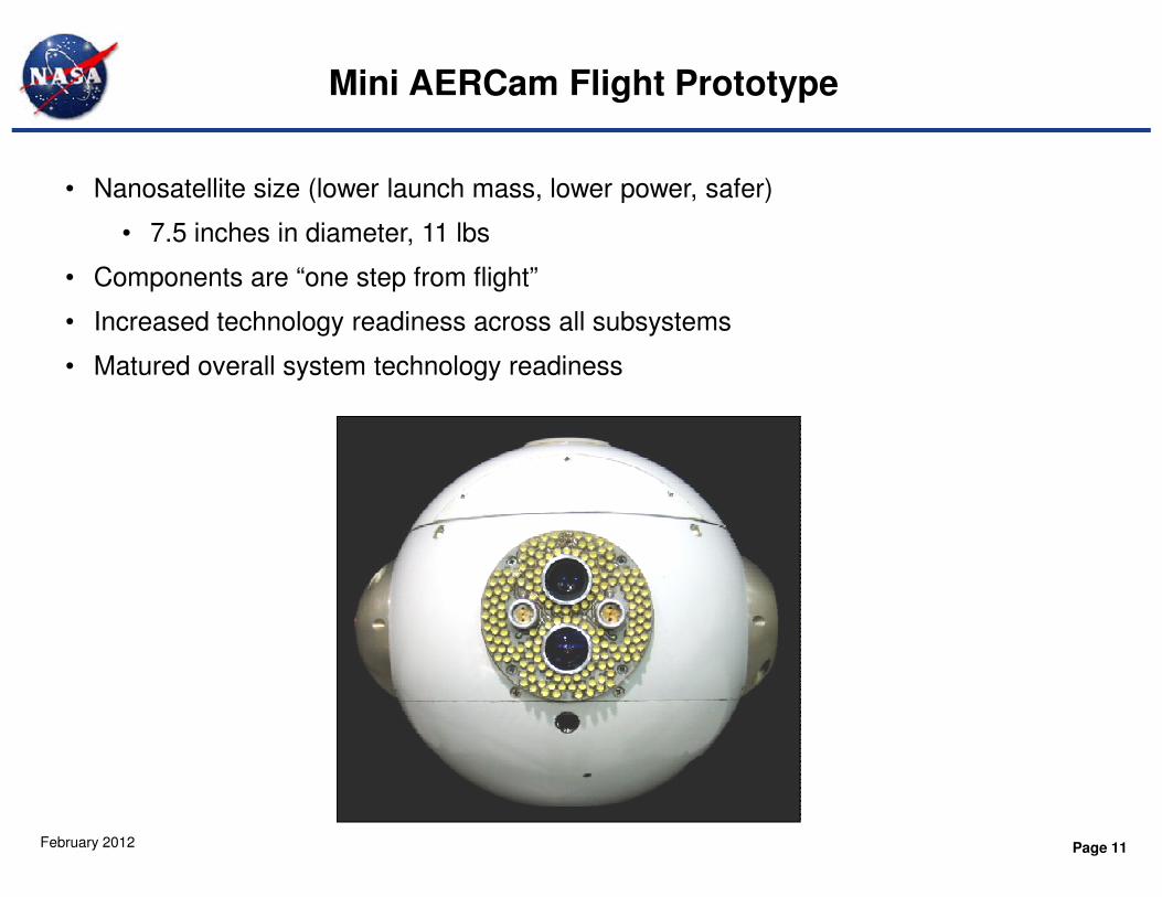
Mini AERCam Flight Prototype
• Nanosatellite size (lower launch mass, lower power, safer)
• 7.5 inches in diameter, 11 lbs
• Components are “one step from flight”
• Increased technology readiness across all subsystems
• Matured overall system technology readiness
Page 11February 2012

Free Flyer Capability Comparison
Sprint:
• 6-DOF manual control
• Automatic attitude hold
• Analog video
Mini AERCam:
• 6-DOF manual control
• Automatic attitude hold
• Commanded attitude maneuvers
• Automatic position hold (relative)
• Commanded translation maneuvers
• Automatic surface scans
• Situational awareness (God’s Eye View)
Page 12February 2012
• Situational awareness (God’s Eye View)
• Digital video
• Automatic docking
• Rechargeable battery
• Rechargeable propulsion

Mini AERCam Flight Prototype Components
Top Hemisphere
Refuel Cluster
Port Camera Cluster
Transceiver Package
Gyro Package
GPS Antenna (x2)
Power Button Cluster
Forward Camera Cluster
Page 13February 2012
GSE Port (x2)
Bottom Hemisphere
Center Structural Ring
GPS ReceiverLED Array
Avionics Board
Thermal Plate
Video Compression Board
Cluster
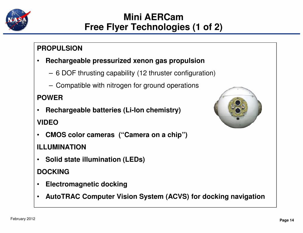
Mini AERCam Free Flyer Technologies (1 of 2)
PROPULSION
• Rechargeable pressurized xenon gas propulsion
– 6 DOF thrusting capability (12 thruster configuration)
– Compatible with nitrogen for ground operations
POWER
• Rechargeable batteries (Li-Ion chemistry)
Page 14February 2012
VIDEO
• CMOS color cameras (“Camera on a chip”)
ILLUMINATION
• Solid state illumination (LEDs)
DOCKING
• Electromagnetic docking
• AutoTRAC Computer Vision System (ACVS) for docking navigation
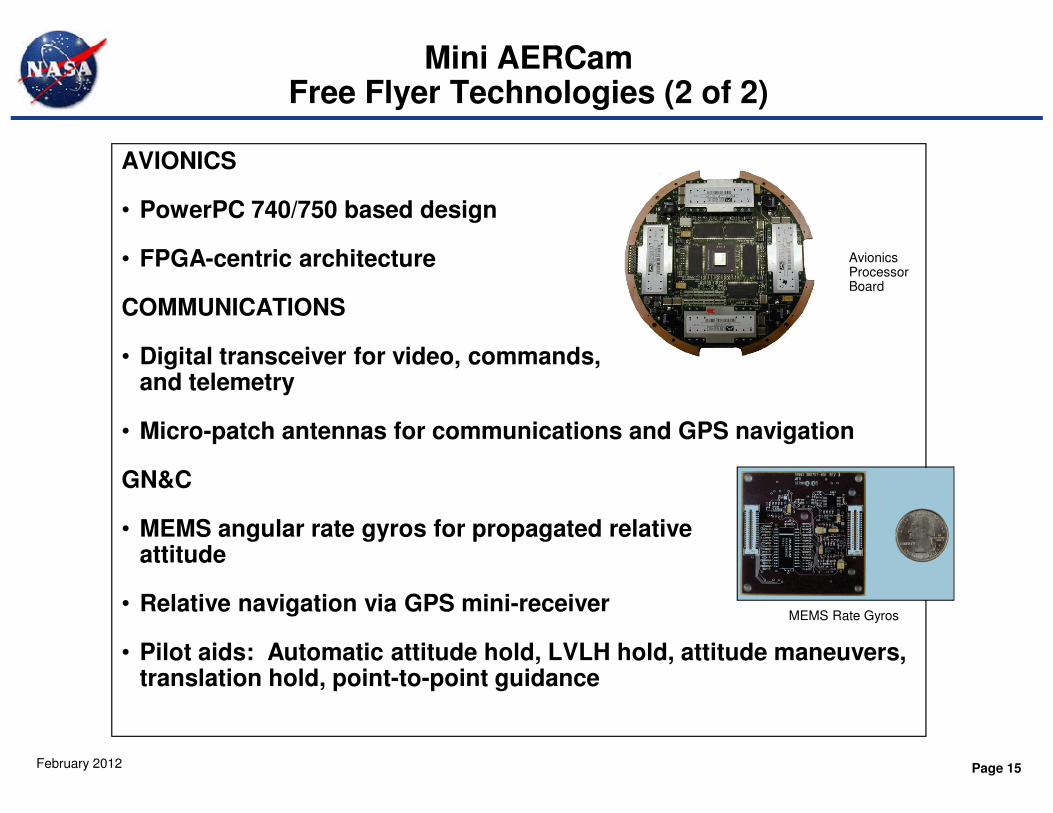
Mini AERCam Free Flyer Technologies (2 of 2)
AVIONICS
• PowerPC 740/750 based design
• FPGA-centric architecture
COMMUNICATIONS
• Digital transceiver for video, commands, and telemetry
Avionics Processor Board
Page 15February 2012
• Micro-patch antennas for communications and GPS navigation
GN&C
• MEMS angular rate gyros for propagated relative attitude
• Relative navigation via GPS mini-receiver
• Pilot aids: Automatic attitude hold, LVLH hold, attitude maneuvers, translation hold, point-to-point guidance
MEMS Rate Gyros

Air Bearing Table Test Facility
Free FlyerControl Station
Displays and Controls
• Provides software and hardware
testing on frictionless surface for
testing in 3 degrees of freedom
• Incorporates avionics, flight
software, video, MEMS gyros,
communications, batteries, and
propulsion.
Page 16February 2012
Hand Controllers
Air Bearing Table “Sled”
Displays and Controls
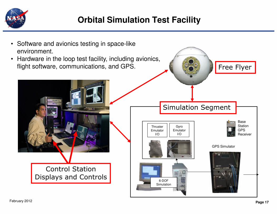
Orbital Simulation Test Facility
Free Flyer
Simulation Segment
• Software and avionics testing in space-like
environment.
• Hardware in the loop test facility, including avionics,
flight software, communications, and GPS.
Page 17February 2012
Control StationDisplays and Controls
Base
Station
GPS
Receiver
GPS Simulator
Thruster
Emulator
I/O
Gyro
Emulator
I/O
6-DOF
Simulation
Simulation Segment
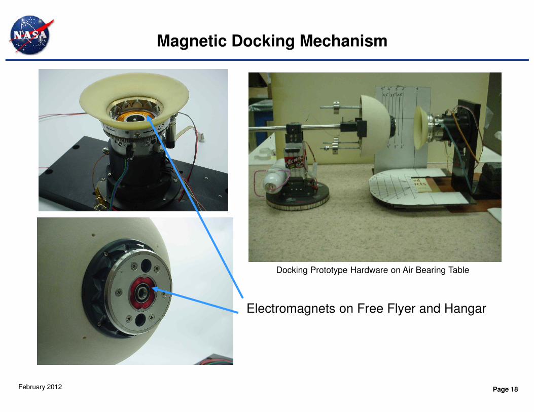
Magnetic Docking Mechanism
Page 18February 2012
Electromagnets on Free Flyer and Hangar
Docking Prototype Hardware on Air Bearing Table

Closed-Loop Docking Airbearing Testing
Page 19February 2012
Mini AERCam Free Flyer on
Airbearing TableDocking port and ACVS
Docking Target

Mini AERCam Docking on Air Bearing Table
Page 20February 2012

Mini AERCam Concept for Shuttle
Wireless Ethernet
uses Shuttle S-
band antennas
Hangar in Shuttle Payload Bay
Shuttle GPS
antennas are used
for relative GPS
FREE FLYER
Page 21February 2012
Shuttle TDRSS
Communications
Control Station inside crew cabin
Ground Monitoring
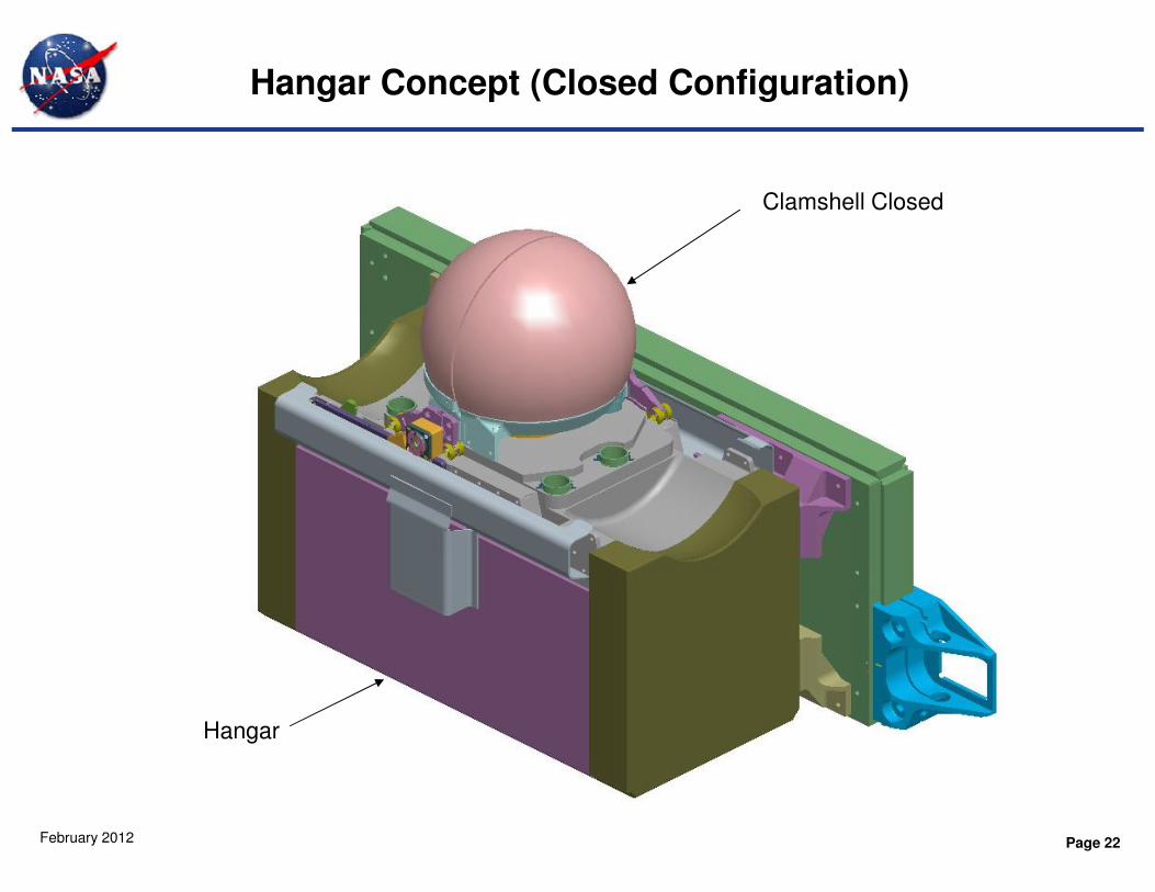
Clamshell Closed
Hangar Concept (Closed Configuration)
Page 22February 2012
Hangar
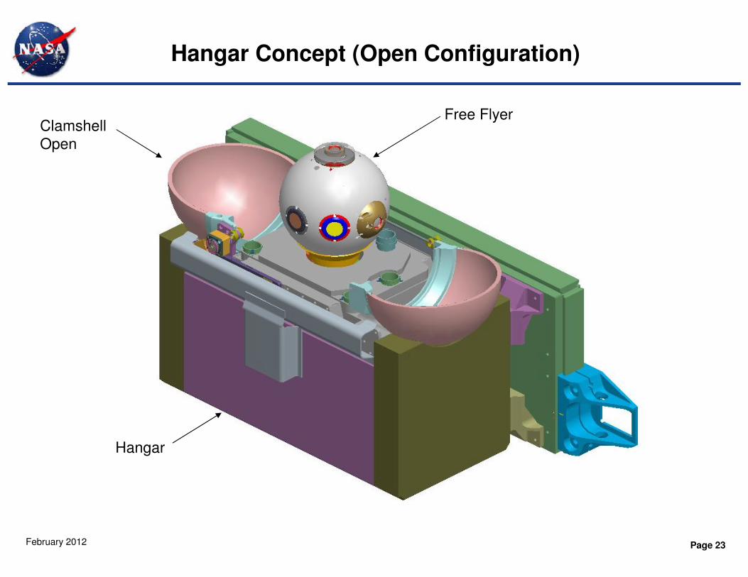
Clamshell
Open
Free Flyer
Hangar Concept (Open Configuration)
Page 23February 2012
Hangar
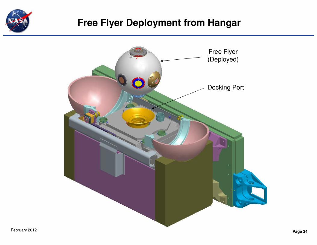
Free Flyer
(Deployed)
Docking Port
Free Flyer Deployment from Hangar
Page 24February 2012
• Free flyer Design Verification Test Unit (DVTU) development
– Imager board designs updated to accommodate higher resolution imagers
» Quad HD high resolution imager (8.3 megapixel)
» HD resolution color video (2.1 megapixel)
– Flight avionics design updated for increased radiation tolerance
– Communication design upgraded to 802.11g (from 802.11b) for higher video
bandwidth
Free Flyer Enhancements for Potential Shuttle Applications
Page 25February 2012
– In-house GPS receiver design developed to replace marginal COTS
alternative
– Mechanical packaging design updated for flight components
– Updated thermal analysis for flight packaging and confirmed passive thermal
design
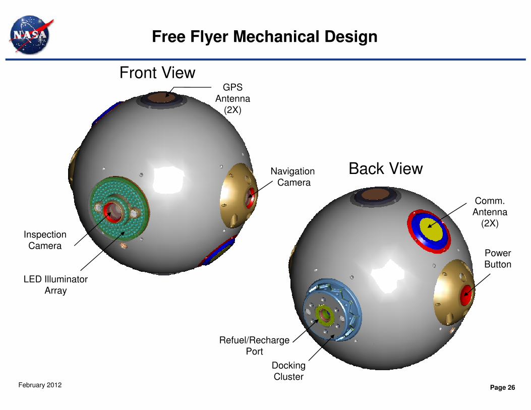
Free Flyer Mechanical Design
Front View
Back ViewNavigationCamera
Comm.
GPSAntenna
(2X)
Page 26February 2012
InspectionCamera
Docking Cluster
Refuel/Recharge Port
PowerButton
Comm.Antenna
(2X)
LED IlluminatorArray

Free Flyer Mechanical Design
GPS Antenna (2X)
Comm. Antenna (2X)
Communications Board
Avionics Processor Board
Thermal Plate
Power Supply Board
Heat exchanger/Propulsion plate
Pressure Regulator
Thruster Valve(12X)
Page 27February 2012
Xenon Tank
Video System Boards
Thermal Plate
GPS Board
Gyro Enclosure
Power ButtonNavigation Camera
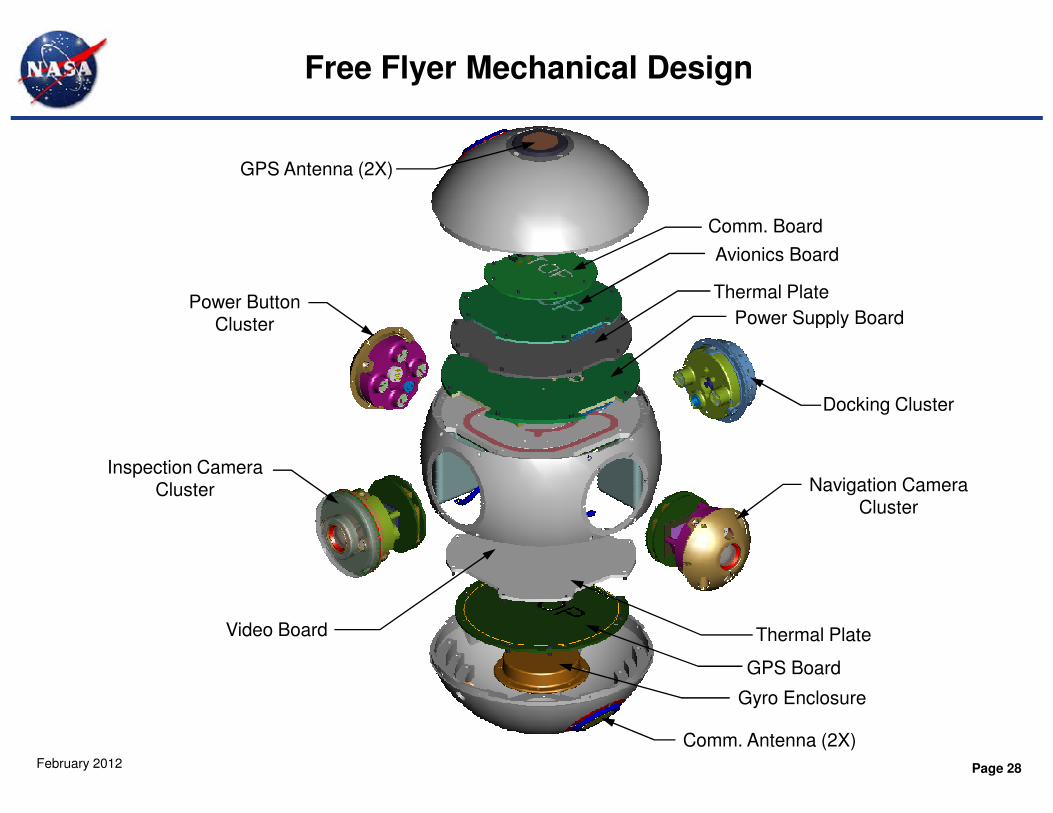
Free Flyer Mechanical Design
Power ButtonCluster
Docking Cluster
Comm. Board
Avionics Board
Thermal Plate
Power Supply Board
GPS Antenna (2X)
Page 28February 2012
Inspection CameraCluster
Docking Cluster
Navigation CameraCluster
Comm. Antenna (2X)
GPS Board
Gyro Enclosure
Thermal PlateVideo Board
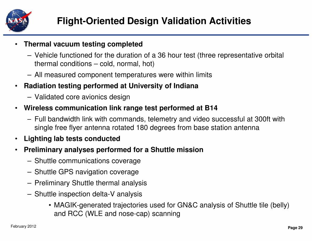
Flight-Oriented Design Validation Activities
• Thermal vacuum testing completed
– Vehicle functioned for the duration of a 36 hour test (three representative orbital
thermal conditions – cold, normal, hot)
– All measured component temperatures were within limits
• Radiation testing performed at University of Indiana
– Validated core avionics design
• Wireless communication link range test performed at B14
– Full bandwidth link with commands, telemetry and video successful at 300ft with
Page 29February 2012
– Full bandwidth link with commands, telemetry and video successful at 300ft with
single free flyer antenna rotated 180 degrees from base station antenna
• Lighting lab tests conducted
• Preliminary analyses performed for a Shuttle mission
– Shuttle communications coverage
– Shuttle GPS navigation coverage
– Preliminary Shuttle thermal analysis
– Shuttle inspection delta-V analysis
• MAGIK-generated trajectories used for GN&C analysis of Shuttle tile (belly)
and RCC (WLE and nose-cap) scanning
Flight-Oriented Design Validation Activities (Cont.)
• Xenon propulsion performance testing
– Xenon is an inert gas that provides 3x the delta-velocity of nitrogen in same
volume, but has different thermodynamic properties
– Hot, ambient and cold case tests confirmed suitability of xenon for free flyer
application
• Battery performance testing for rechargeable Li-Ion battery cells
– Cell testing confirmed high performance over temperature range
Page 30February 2012
• Crew evaluation – Displays (2003)
– Nancy Currie and the Astronaut Office made significant recommendations for
improving displays during crew evaluation preparations
» All tasks completed successfully with no significant problems identified
• Crew evaluation – Hand controller (2005)
– Conducted evaluation of a hand-held control pad input device concept that would
eliminate requirement for hard-mounting hand controllers in the Orbiter
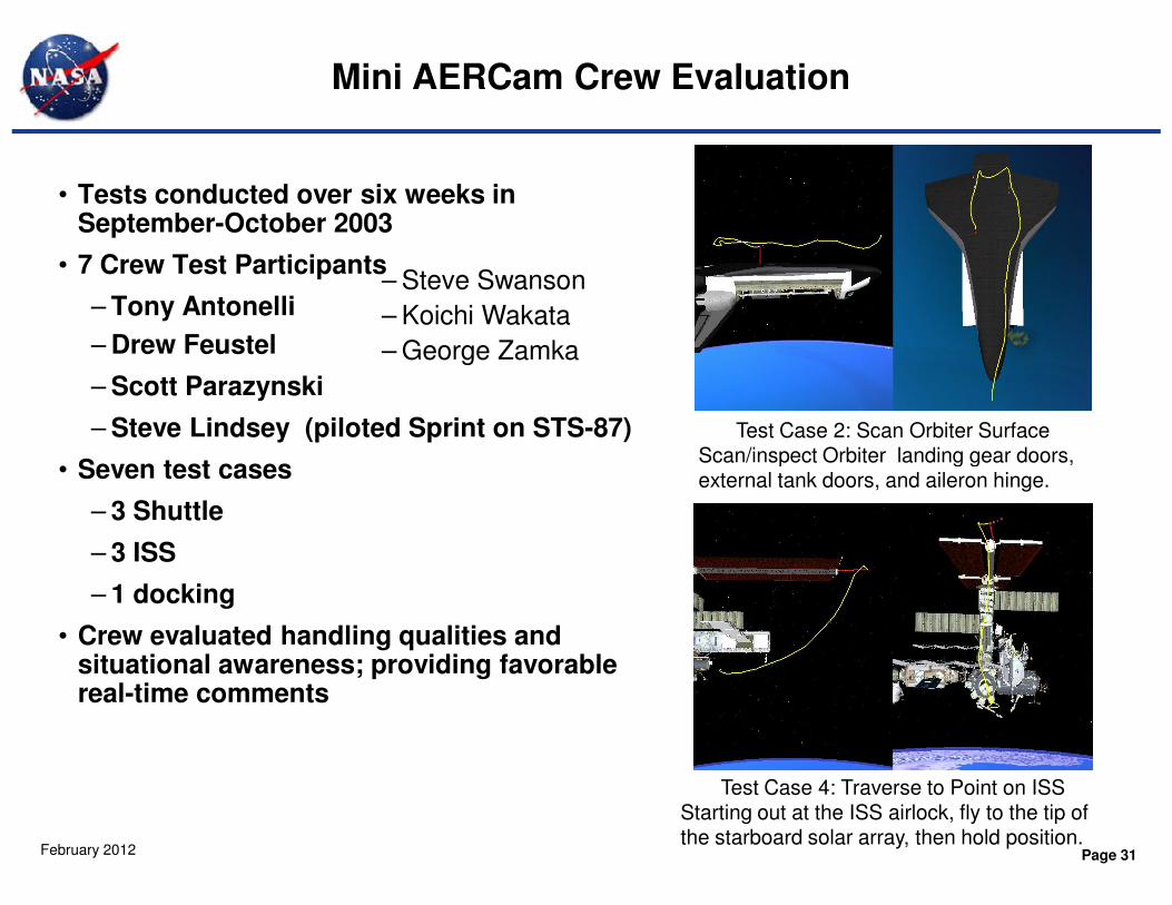
• Tests conducted over six weeks in September-October 2003
• 7 Crew Test Participants
– Tony Antonelli
– Drew Feustel
– Scott Parazynski
– Steve Lindsey (piloted Sprint on STS-87)
Mini AERCam Crew Evaluation
Test Case 2: Scan Orbiter SurfaceScan/inspect Orbiter landing gear doors,
– Steve Swanson
– Koichi Wakata
– George Zamka
Page 31February 2012
• Seven test cases
– 3 Shuttle
– 3 ISS
– 1 docking
• Crew evaluated handling qualities and situational awareness; providing favorable real-time comments
Scan/inspect Orbiter landing gear doors, external tank doors, and aileron hinge.
Test Case 4: Traverse to Point on ISSStarting out at the ISS airlock, fly to the tip of the starboard solar array, then hold position.
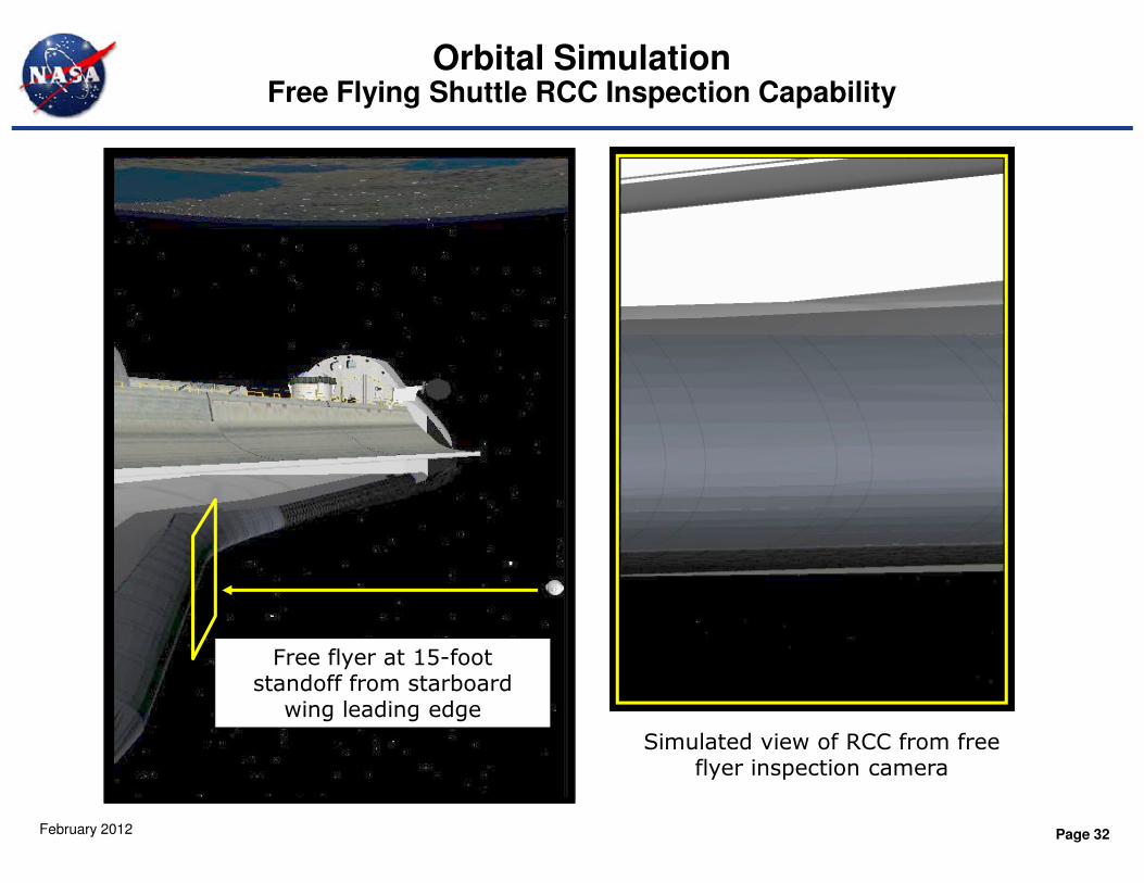
Orbital SimulationFree Flying Shuttle RCC Inspection Capability
Page 32February 2012
Simulated view of RCC from free flyer inspection camera
Free flyer at 15-foot standoff from starboard
wing leading edge
Related development and testing continued under other sponsorship
• Avionics processor board firmware development and VxWorks hosting for ETDP AR&D
• DRAGON GPS re-spin and development for University Cubesat application
• Video board assembly and software development using a TI DSP development board and an in-house frame grabber (Co-op project)
Page 33February 2012
grabber (Co-op project)
• Hangar DVTU/prototype integration for NextFest
• ACVS testing for ETDP AR&D
• Natural Features Identification and Recognition (NFIR) navigation testing for ETDP AR&D – applicable to AERCam navigation beyond GPS range (e.g. lunar orbit)
• Miniature Xenon fluid system integration/operations (CDDF project)
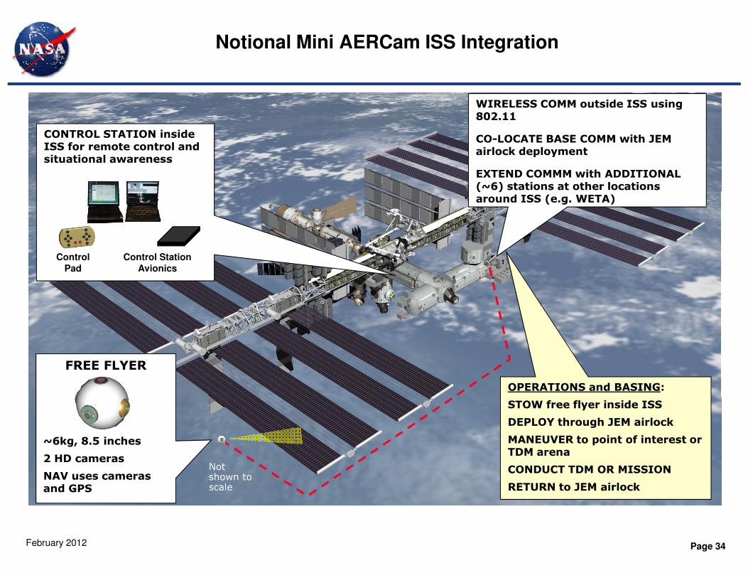
Notional Mini AERCam ISS Integration
CONTROL STATION inside ISS for remote control and situational awareness
Control Station
Avionics
Control
Pad
WIRELESS COMM outside ISS using 802.11
CO-LOCATE BASE COMM with JEM airlock deployment
EXTEND COMMM with ADDITIONAL (~6) stations at other locations around ISS (e.g. WETA)
Page 34February 2012
FREE FLYER
~6kg, 8.5 inches
2 HD cameras
NAV uses cameras and GPS
OPERATIONS and BASING:
STOW free flyer inside ISS
DEPLOY through JEM airlock
MANEUVER to point of interest or TDM arena
CONDUCT TDM OR MISSION
RETURN to JEM airlock
Not shown to scale
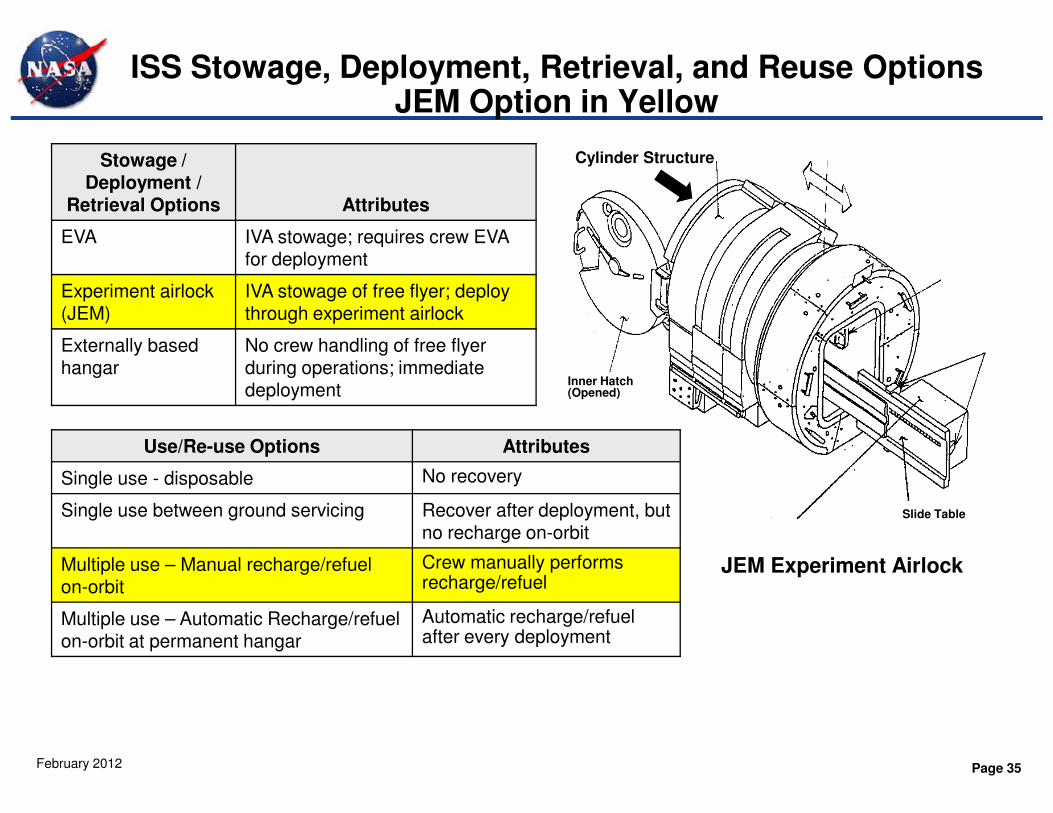
ISS Stowage, Deployment, Retrieval, and Reuse OptionsJEM Option in Yellow
Inner Hatch (Opened)
Cylinder StructureStowage / Deployment /
Retrieval Options Attributes
EVA IVA stowage; requires crew EVA for deployment
Experiment airlock (JEM)
IVA stowage of free flyer; deploy through experiment airlock
Externally based hangar
No crew handling of free flyer during operations; immediate deployment
Page 35February 2012
JEM Experiment Airlock
Slide Table
Use/Re-use Options Attributes
Single use - disposable No recovery
Single use between ground servicing Recover after deployment, but no recharge on-orbit
Multiple use – Manual recharge/refuel on-orbit
Crew manually performs recharge/refuel
Multiple use – Automatic Recharge/refuel on-orbit at permanent hangar
Automatic recharge/refuel after every deployment
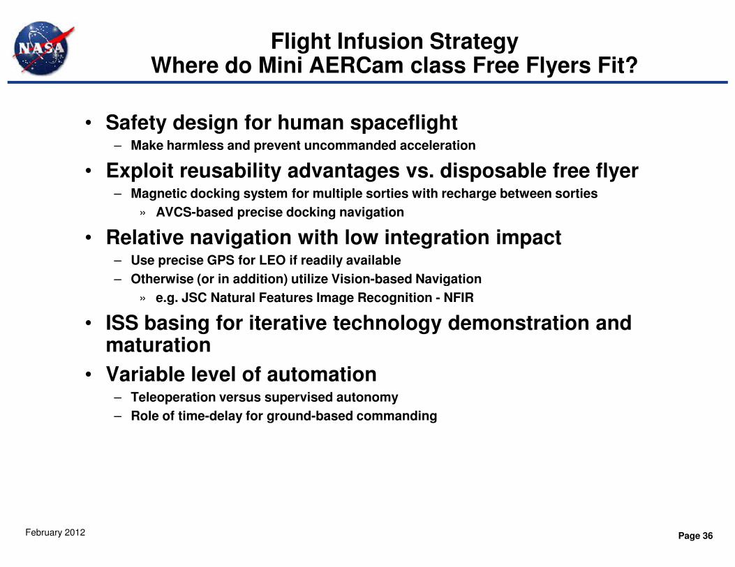
Flight Infusion StrategyWhere do Mini AERCam class Free Flyers Fit?
• Safety design for human spaceflight– Make harmless and prevent uncommanded acceleration
• Exploit reusability advantages vs. disposable free flyer– Magnetic docking system for multiple sorties with recharge between sorties
» AVCS-based precise docking navigation
• Relative navigation with low integration impact– Use precise GPS for LEO if readily available
– Otherwise (or in addition) utilize Vision-based Navigation
Page 36February 2012
– Otherwise (or in addition) utilize Vision-based Navigation
» e.g. JSC Natural Features Image Recognition - NFIR
• ISS basing for iterative technology demonstration and maturation
• Variable level of automation– Teleoperation versus supervised autonomy
– Role of time-delay for ground-based commanding