MINEX - ach.nuMINEX®-S offers an overload protection function of the drive train. After removing...
10
MINEX ® -S Magnetic coupling 179 You will find continuously updated data in our online catalogue at www.ktr.com MINEX ® -S MINEX ® -S Magnetic coupling
Transcript of MINEX - ach.nuMINEX®-S offers an overload protection function of the drive train. After removing...
MINEX®-S Magnetic coupling
179You will find continuously updated data in our online catalogue at www.ktr.com
MIN
EX
®-S
MINEX®-SMagnetic coupling
MINEX®-S Magnetic coupling
180 You will find continuously updated data in our online catalogue at www.ktr.com
Table of contents
MINEX®-SMagnetic coupling 179Coupling description 181Technical description 182Sizes SA 22/4 to SB 60/8 with containment shroud made of stainless steel 183Sizes SA 75/10 to SF 250/38 with containment shroud made of stain-less steel or Hastelloy 184
Sizes SA 75/10 to SE 165/24 with containment shroud made of PEEK 186Sizes SA 110/16 to SE 200/30 with containment shroud made of oxide ceramics 187
Mounting sets and customized assemblies 188
NEW

MINEX®-S Magnetic coupling
181You will find continuously updated data in our online catalogue at www.ktr.com
MIN
EX
®-S
Coupling description
Containment shroud
Internal rotor
Run of flux lines
External rotor
Mode of operation/DesignTorque transmissionThe coupling consists of an external and an internal rotor. The external rotor has high-quality, permanent magnets of changing polarity on the inner side and the internal rotor has them on the outside.The external rotor is normally fixed on the drive side and the magnets are glued in the keyways.The magnets of the driven-sided internal rotor are cylindrically ground to ensure a minimal air gap and encapsulated through a magnetic cover that is impervious to fluids.In their non-operative states the north and south poles of the rotors are opposite to each other and the magnetic field is completely symmetric.It is only when the rotors are twisted that the magnetic field lines are moved, hence the torque is transmitted through the air gap. Then there is a synchronous opera-tion under a constant torsion angle. If the maximum coupling torque and the maxi-mum torsion angle are exceeded, the power transmission is interrupted. Thus the MINEX®-S offers an overload protection function of the drive train. After removing the cause of the overload (e. g. damage to the bearing, blocking of the internal rotor) both rotors can be synchronised again and operation is resumed.
General descriptionMINEX®-S is a permanent-magnetic synchronous coupling that transmits the torque through magnetic forces between the internal and the external rotor. It ensures a hermetic separation of the drive and the driven side in its main function as sealing element in pumps and agitators. For critical media like aggressive acids, bases, etc. it serves as a reliable seal and prevents serious leakages occuring. On request KTR will manufacture special customer-specific types of the MINEX®-S in combination with KTR hydraulic components. Thus existing pumps with a conven-tional shaft seal can be easily retrofitted with the MINEX®-S.
Sealing functionThe main component of the MINEX®-S is the containment shroud that is fixed to the driven-sided power unit and separates internal and external rotor from each other. It ensures a low-vibration torque transmission working without mechanical connection and guarantees a completely leak-proof separation of product and atmosphere. The sealing is achieved with a flat seal or an O-ring, thus eliminating the need to dynami-cally load the sealing elements.The standard designs of MINEX®-S include metallic containment shrouds made of stainless steel or Hastelloy, respectively. Inside the rotating magnetic field they generally cause losses of eddy current which are converted into heat and which may require cooling measures. On applications with pumps the heat produced can basically be dissipated by the medium to be pumped.If eddy current losses can be definitely excluded, the energy-efficient alternative ma-terials PEEK and ceramics are available. PEEK is first class with rather low pressures and temperatures (depending on size up to 16 bar and 130 °C). For higher performances up to 25 bar and 300 °C we would recommend to use containment shrouds made of ceramics.

MINEX®-S Magnetic coupling
182 You will find continuously updated data in our online catalogue at www.ktr.com
Technical data
Size
Stat. tear torque
TK max. with 20 °C [Nm]
External rotor Internal rotor Containment shroud
Standard material Max. operating tempera-ture tmax.
[°C]
Weight unbored
[kg]
Mass moment of inertia J with min. bore Ø [kgm2]
Standard material Max. opera ting
tempera ture
tmax. [°C]
Weight pilot bored
[kg]
Mass moment of inertia J with min.
bore Ø [kgm2]
Standard material 2) Max. pressure
resistance pN/pmax.
1)[bar]
Max. operating
speed [rpm]Hub Magnets Hub Magnets Flange Shroud
SA 22/4 0,15NdFeB 150
0,13 30,01 x 10⁻⁶
1.4462 NdFeB 1500,04 1,912 x 10-6 60/90
SA 34/10 1 0,26 117,4 x 10⁻⁶ 0,09 12,1 x 10⁻⁶
16/24SA 46/6 3 0,62 458,6 x 10⁻⁶ 0,32 125 x 10-6
SA 60/8 7 1,75 2279 x 10-6 0,56 221 x 10-6
40/60SB 60/8 14 2,68 3759 x 10-6 0,93 380 x 10-6
SA 75/10 10 1,36 3159 x 10-6 0,94 539 x 10-6
SB 75/10 24 2,10 4829 x 10-6 1,49 889 x 10-6
SC 75/10 40 2,89 6654 x 10-6 1,89 1232 x 10-6
SB 110/16 60 2,82 12111 x 10-6 3,73 5229 x 10-6
SC 110/16 95 3,79 16238 x 10-6 4,85 7137 x 10-6
SB 135/20 100 3,75 22878 x 10-6
3005,67 12333 x 10-6
SC 135/20 145 4,90 29874 x 10-6 7,36 16768 x 10-6
25/37.5SD 135/20 200 6,06 36870 x 10-6 9,50 22387 x 10-6
SC 165/24 210 5,31 45480 x 10-6 11,40 37917 x 10-6
SD 165/24 280 6,56 56170 x 10-6 14,67 50633 x 10-6
SE 165/24 370 7,81 66860 x 10-6 17,30 60855 x 10-6
SD 200/30 430300
9,89 117296 x 10-6 26,06 125915 x 10-6
SE 200/30 550 10,36 122342 x 10-6 26,11 126405 x 10-6
SD 250/38 670 10,93 202540 x 10-6 37,92 282795 x 10-6 16/24SE 250/38 820 13,03 241273 x 10-6 45,22 340420 x 10-6
SF 250/38 1000 15,13 280000 x 10-6 52,50 397915 x 10-6
Description Symbol Definition or explanation
Static tear torque of coupling TK max. Max. transmittable torque, from which onwards the magnetic forces tear during the static test.
Description Symbol Definition or explanation
Maximum operating tem-perature tmax.
Max. permissible temperature causing a tempo-rary attenuation of the magntic field. Exceeding may generate irretrievable losses of magnetiza-
tion.
Technical description
110 %
105 %
100 %
95 %
90 %
85 %
80 %
75 %
70 %20 50 100 150 200 250 300
Torque reduction with temperature increase
Con
stru
ctio
n st
eel S
355J
2G3
Sam
ariu
m-c
obal
t (S
m2C
o17)
Sam
ariu
m-c
obal
t (S
m2C
o 17)
or
neod
ymiu
m-ir
on-b
oron
(NdF
eB)
300
°C (S
m2C
o 17)
or
150
°C (N
dFeB
)
Sta
inle
ss s
teel
1.4
571
Sam
ariu
m-c
obal
t (S
m2C
o17)
Sta
inle
ss s
teel
1.4
571
Sta
inle
ss s
teel
1.45
71 o
r
Has
tello
y
16/2
4 ba
r
with
1.4
571,
25/3
7.5
bar
with
Has
tello
y
Has
tello
yS
tain
less
ste
el
1.45
71
3600
rpm
usi
ng m
etal
sta
tiona
ry c
onta
inm
ent s
hrou
ds a
s pe
r KTR
st
anda
rd
Please note:KTR recommends to use NdFeB magnets for the external rotor, provided that the operating temperature falls below 150 °C.
Explosion-protection useMINEX®-S couplings are suitable for the power transmission in drives that are scheduled to be used in explosive areas. According to the EU standards 94/9/EC (ATEX 95) the types with metallic contain-ment shrouds are assessed and confirmed as components of the device class II and suitable for the use in explosive areas of category 2G.Please see our website www.ktr.com for advice, copies of certification and operating/mounting in-structions.
T max
. ref
erre
d to
nom
inal
val
ue
(see
tabl
e) in
per
cen
t [%
]%]
Temporary torque reduction with increased temperature for alternative material combinations [%]
Temperature [°C]
Material combination SmCo/SmCo
Material combination SmCo/NdFeB
1) Resistances to higher pressures can be realized on request of the customer.2) Alternative containment shroud materials like oxide ceramics (see page 187) und PEEK (see page 186) are available on request.

183You will find continuously updated data in our online catalogue at www.ktr.com
MIN
EX
®-S
MINEX®-S Magnetic coupling
Technical data – Internal rotor and containment shroud
SizeTK max.
[Nm] with ~ 20 °C
Dimensions [mm]Internal rotor Containment shroud
Finish bore 1) diDI1 LI1
SIGI DS1 DS2 DS3 DS4 ZSmin max. min. max.
SA 22/4 0,15 5 9 20 20 2,0 2,0 M3 21,5 38 46 4,5 8SA 34/10 1 5 12 20 22 2,0 5,5 M3 34 46 55 4,5 4SA 46/6 3 8 16 28 33 6,5 7,0 M4 46 – 78 – –SA 60/8 7
12 22 3636 2,2 3,5
M5 59 75 89,5 5,5 8SB 60/8 14 56 0,0 3,5
Technical data – External rotor and general
Size
Dimensions [mm]External rotor General
Finish bore 1) daDA1 DA3 LA1 LA2 ΔS GA DS6 DA5
Ltotalmin. max.
SA 22/4 5 11 18 38 35 8,5 5,0 M4 23,5 24,8 42 42SA 34/10 5 14 22 53 38,5 10,5 5,5 M4 36,0 37,3 46 49,5SA 46/6 5 24 40 69,5 53 16 9,0 M5 48,5 49,4 68,5 69,5SA 60/8 9 32
50 94,566 19
12,0M6 61,0 63,2 80 81,3
SB 60/8 9 38 93 15 M8 61,5 63,2 105 108
MINEX® SA 60/8 NdFeB di Ø20mm da Ø24mm
Coupling size NdFeB – tmax. = 150 °CSm2Co17 – tmax. = 300 °C Finish bore (H7) feather keyway to DIN 6885 sheet 1 (JS9)
Sizes SA 22/4 to SB 60/8 with containment shroud made of stainless steel z Contactless torque transmission z Hermetic separation of driving and driven side z Containment shroud made of stainless steel 1.4571 z Available from stock with pilot bored internal rotor and unbored external rotor
z Finish bore possible to ISO H7, feather keyway to DIN 6885 sheet 1 - JS9
z -Approved and certified according to EC Standard 94/9/EC
z Mounting instructions available at www.ktr.com
Internal rotorContainment shroudExternal rotor
1) Bore H7 with feather keyway DIN 6885, sheet 1 [JS9]
Ordering example:

184 You will find continuously updated data in our online catalogue at www.ktr.com
MINEX®-S Magnetic coupling
MINEX® SB 75/10 NdFeB di Ø20mm da Ø24mm Hastelloy
Coupling size NdFeB – tmax. = 150 °CSm2Co17 – tmax. = 300 °C
Finish bore (H7), feather keyway to DIN 6885 sheet 1 (JS9)
Containment shroud type
Sizes SA 75/10 to SF 250/38 with containment shroud made of stainless steel or Hastelloy z Contactless torque transmission z Hermetic separation of driving and driven side z As an alternative containment shroud made of stainless steel 1.4571 or Hastelloy
z Two-part external rotor with flange hub that must be separately screwed, customer-specific variations are possible
z Available from stock with pilot bored internal rotor z Finish bore possible to ISO fit H7, feather keyway to DIN 6885 sheet 1 - JS9
z -Approved and certified according to EC Standard 94/9/EC
Internal rotorContainment shroudExternal rotorOptional flange hub with bore da
Ordering example:
MINEX®-S Magnetic coupling
185You will find continuously updated data in our online catalogue at www.ktr.com
MIN
EX
®-S
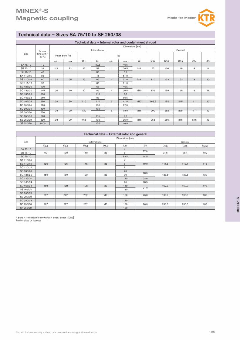
Technical data – Internal rotor and containment shroud
SizeTK max.
[Nm] with ~ 20 °C
Dimensions [mm]Internal rotor General
Finish bore 1) di
DI1 LI1
SI
GI DS1 DS2 DS3 DS4 ZSmin. max. min. max.SA 75/10 10 39,5 46,5SB 75/10 24 12 32 45 58 4 26,5 M6 75 100 118 9 8SC 75/10 40 80 6,0SA 110/16 25 45 51,0SB 110/16 60 14 55 72 65 4 31,0 M8 110 133 153 9 12SC 110/16 95 85 11,0SB 135/20 100 65 46,5SC 135/20 145 20 70 90 85 4 26,5 M10 135 158 178 9 16SD 135/20 200 110 7,0SC 165/24 210 85 66,5SD 165/24 280 24 90 110 110 6 41,0 M12 163,5 192 218 11 12SE 165/24 370 130 22,0SD 200/30 430
38 90 130135
6 18,0 M16 200 252 278 11 12SE 200/30 550SD 250/38 670 115 7,0SE 250/38 820 38 90 165 135 – 26,0 M16 255 285 315 13,5 12SF 250/38 1000 155 46,0
Technical data – External rotor and general
SizeDimensions [mm]
External rotor GeneralDA1 DA2 DA3 DA4 LA1 ΔS DS6 DA5 Ltotal
SA 75/10 4112,5
SB 75/10 90 100 110 M6 61 74,6 76,4 102SC 75/10 83,5 14,5SA 110/16 41SB 110/16 126 135 145 M6 61 19,0 111,5 113,1 115SC 110/16 81SB 135/20 70
18,5SC 135/20 150 160 170 M6 90 136,5 138,5 139SD 135/20 110 22,0SC 165/24 90 18,5SD 165/24 150 188 198 M6 110
21,0167,0 169,2 170
SE 165/24 130SD 200/30
212 222 232 M6 130 26,0 198,0 199,5 180SE 200/30SD 250/38 110SE 250/38 267 277 287 M6 130 26,0 253,0 255,0 183SF 250/38 150
Technical data – Sizes SA 75/10 to SF 250/38
1) Bore H7 with feather keyway DIN 6885, Sheet 1 [JS9]Further sizes on request.

186 You will find continuously updated data in our online catalogue at www.ktr.com
MINEX®-S Magnetic coupling
NEW
SA = Sl + ΔS
Technical data – Internal rotor and containment shroud
SizeTK max.
[Nm] with ~ 20 °C
Dimensions [mm]Internal rotor Containment shroud
Fertigbohrung 1) diDI1 LI1
SIGI DS1 DS2 DS3 DS4 DS5 ZSmin. max. min. max.
SA 75/10 10 39,57,5
54,5SB 75/10 24 12 28 45 58 35,5 M6 100 115 135 9,0 72,1 8SC 75/10 40 80 5,5 13,5SA 110/16 30 45 45,0SB 110/16 70 14 55 80 65 4,0 25,0 M8 140 151 168 9,0 109,3 12SC 110/16 100 85 5,0SB 135/20 110 65 48,0SC 135/20 155 20 70 90 85 4,0 28,0 M10 157 167 180 5,5 133,9 12SD 135/20 210 110 4,0SC 165/24 220 85
4,032,0
SD 165/24 300 24 90 110 110 8,0 M12 196 210 225 6,6 163,8 12SE 165/24 390 130 0,0 0,0
Technical data – External rotor and general
SizeDimensions [mm]
External rotor GeneralDA1 DA2 DA3 DA4 LA1 ΔS DS6 DA5 Ltotal
SA 75/10 4112,5
SB 75/10 90 100 110 M6 61 75,1 76,5 108SC 75/10 83,5 14,5SA 110/16 41SB 110/16 130 138 150 M6 61 19 113,2 115,7 115SC 110/16 81SB 135/20 70
18,5SC 135/20 158 167 176 M6 90 138,2 141,9 144SD 135/20 110 21SC 165/24 90 18
156SD 165/24 182 191 200 M6 110
21168,3 172,0
SE 165/24 130 160
MINEX® SB 75/10 NdFeB di Ø20mm da Ø24mm PEEK
Coupling size NdFeB – tmax. = 150 °CSm2Co17 – tmax. = 300 °C
Finish bore (H7), feather keyway to DIN 6885 sheet 1 (JS9) Containment shroud type
Ordering example:
Sizes SA 75/10 to SE 165/24 with containment shroud made of PEEK
1) Bore H7 with feather keyway DIN 6885 sheet 1 [JS9]
Internal rotor
Containment shroud with
clamping ring 2)
External rotor
Optional flange hub
with bore da
z No eddy current losses and consequently no generation of heat in the coupling caused by the containment shroud
z Low susceptibility to fracture, low weight, easy handling z Optimal solution with low demands on temperature and pres-sure resistance (up to 16 bar and 130 °C)
z Internal cooling measures are not required z High energy efficiency and cost effectiveness z The selection torque may be reduced by 10 - 15 % z Suitable for dry-running drives like compressors and vacuum pumps, but also agitators, polyurethane plants, etc.
2) Containment shroud size 75 also available as a single parted design!

187You will find continuously updated data in our online catalogue at www.ktr.com
MIN
EX
®-S
MINEX®-S Magnetic coupling
SA = Sl + ΔS
Technical data – Internal rotor and containment shroud
SizeTK max.
[Nm] with ~ 20 °C
DimensionsInternal rotor Containment shroud
Finish bore 1) diDI1 LI1
SIGI DS1 DS2 DS3 DS4 ZSmin. max. min. max.
SA 110/16 25 45 49,0SB 110/16 60 14 55 72 65 4,0 29,0 M8 119,5 148 162 5,5 12SC 110/16 95 85 9,0SB 135/20 100 65 46,5SC 135/20 145 20 70 90 85 4,0 26,5 M10 145 173 187 5,5 12SD 135/20 200 110 7,0SC 165/24 210 85 3,5 28,0SD 165/24 280 24 90 110 110 – 4,0 M12 188 210 226 6,6 12SE 165/24 370 130 6,0 14,0SD 200/30 430
38 90 130 135 6,0 14,0 M16 242 272 294 9,0 12SE 200/30 550
Technical data – External rotor and general
SizeDimensions [mm]
External rotor GeneralDA1 DA2 DA3 DA4 LA1 ΔS DS6 DA5 Ltotal
SA 110/16 41SB 110/16 126 135 145 M6 61 19,0 111,5 113,1 115SC 110/16 81SB 135/20 70
18,5SC 135/20 150 160 170 M6 90 136,5 138,5 139SD 135/20 110 22,0SC 165/24 90 18,5SD 165/24 180 188 198 M6 110
21,0167,0 169,2 170
SE 165/24 130SD 200/30
212 222 232 M6 130 26,0 198,0 199,5 180SE 200/30
MINEX® SB 135/20 NdFeB di Ø20mm da Ø24mm Oxide ceramics ZrO2MgO
Coupling size NdFeB – tmax. = 150 °CSm2Co17 – tmax. = 300 °C
Finish bore (H7), feather keyway to DIN 6885 sheet 1 (JS9) Containment shroud type
Ordering example:
Sizes SA 110/16 to SE 200/30 with containment shroud made of oxide ceramics
1) Bore H7 with feather keyway DIN 6885 sheet 1 [JS9]
Internal rotorContainment shroud with
clamping ring
External rotor
Optional flange hub with bore
da
z No eddy current losses and consequently no generation of heat in the coupling caused by the containment shroud
z Suitable for higher demands on temperature and pressure re-sistance (up to 25 bar and 300 °C)
z Internal cooling measures are usually not required z High energy efficiency and cost effectiveness z The selection torque may be reduced by 10 - 15 % z Suitable for dry-running drives like compressors and vacuum pumps, but also agitators, polyurethane plants, etc.
z Sizes SA 110/16 to SE 200/30 available from stock, other sizes on request
z -Approved and certified according to EC Standard 94/9/EC

MINEX®-S Magnetic coupling
188 You will find continuously updated data in our online catalogue at www.ktr.com
Mounting sets and customized assemblies
Examples of application
On request KTR can offer special customer-specific solutions in combination with hydraulic components from KTR, whereby existing systems can be easily retrofitted with the MINEX®-S.
Conveying and proportioning the media polyol and isocyanate in the processing plants for PUR, ambient air has to be prevented from penetrating into the process, since oth-erwise unrequested reactions may be produced.For a reliable sealing of such drives KTR offers standard sets for retrofitting, among oth-ers for axial piston pumps types REXROTH A2VK and ROTARY POWER C series offering the following benefits:
z Maintenance-free operation z Standstill periods are considerably reduced z No more problems with sealing z Better efficiency and process safety
The assemblies are available for all motor-pump-combinations and in various materials.
Axial piston pump REXROTH type A2VK
Retrofitting of a gear pump with MINEX® SA 75/10, bellhousing PK 200/30, base flange and damping rod
Maintenance-free sealing of dosing pumps for polyde and isocyanate in high-pressure reaction casting machines
MINEX®-S for the separation of autoclaves (T.B.M./STERICHEM) in laboratories and clinics
Use of the MINEX®-S in a small centrifugal pump MINEX®-S for sealing homogenizers for heavy oil processing in marine operation
Adapter flange KTR bellhousing
Containment shroud
Internal rotor
External rotor Flange hub Distance rings
Technical data for coupling selection/selection of componentsMotor type Pump type
Power kW Speed rpm
Pressure bar Temperature °C
Viscosity of medium mm²/s Max. perm. dimensions ØD x Ltotal
Retrofitting sets for PUR foaming processes