MIMO block spread OFDMA system for next generation mobile ...
112
University of Wollongong Theses Collection University of Wollongong Theses Collection University of Wollongong Year MIMO block spread OFDMA system for next generation mobile communications Yiwei Yu University of Wollongong Yu, Yiwei, MIMO block spread OFDMA system for next generation mobile communications, MEngStud thesis, School of Electrical, Computer and Telecommunications Engineering, University of Wollongong, 2008. http://ro.uow.edu.au/theses/110 This paper is posted at Research Online. http://ro.uow.edu.au/theses/110
Transcript of MIMO block spread OFDMA system for next generation mobile ...

University of Wollongong Theses Collection
University of Wollongong Theses Collection
University of Wollongong Year
MIMO block spread OFDMA system for
next generation mobile communications
Yiwei YuUniversity of Wollongong
Yu, Yiwei, MIMO block spread OFDMA system for next generation mobile communications,MEngStud thesis, School of Electrical, Computer and Telecommunications Engineering,University of Wollongong, 2008. http://ro.uow.edu.au/theses/110
This paper is posted at Research Online.
http://ro.uow.edu.au/theses/110


MIMO Block Spread OFDMA System for
Next Generation Mobile Communications
A thesis submitted in partial fulfilment of the requirements for the award of thedegree
Master of Engineering by Research
from
UNIVERSITY OF WOLLONGONG
by
Yiwei YuMaster of Engineering Studies
School of Electrical, Computer and Telecommunications Engineering
March 2008

Statement of Originality
I, Yiwei Yu, declare that this thesis, submitted in partial fulfilment of the require-
ments for the award of Master of Engineering - Research, in the School of Electri-
cal, Computer and Telecommunications Engineering, University of Wollongong, is
wholly my own work unless otherwise referenced or acknowledged. The document
has not been submitted for qualifications at any other academic institution.
Yiwei Yu
March 26, 2008
I
Contents
Acronyms VIII
Abstract XII
Acknowledgments XIV
1 Introduction 1
1.1 Research objectives . . . . . . . . . . . . . . . . . . . . . . . . . . . . 2
1.2 Thesis organization . . . . . . . . . . . . . . . . . . . . . . . . . . . . 4
1.3 Contributions . . . . . . . . . . . . . . . . . . . . . . . . . . . . . . . 5
1.4 Publication . . . . . . . . . . . . . . . . . . . . . . . . . . . . . . . . 6
2 Overview of 4G 8
2.1 Evolution towards 4G . . . . . . . . . . . . . . . . . . . . . . . . . . . 8
2.1.1 History of wireless communications . . . . . . . . . . . . . . . 9
2.1.2 4G features . . . . . . . . . . . . . . . . . . . . . . . . . . . . 10
2.2 Modulation techniques for 4G . . . . . . . . . . . . . . . . . . . . . . 13
2.2.1 Multicarrier systems . . . . . . . . . . . . . . . . . . . . . . . 13
2.2.2 OFDM . . . . . . . . . . . . . . . . . . . . . . . . . . . . . . . 15
II
2.2.3 OFDMA . . . . . . . . . . . . . . . . . . . . . . . . . . . . . . 17
2.2.4 Multicarrier CDMA . . . . . . . . . . . . . . . . . . . . . . . . 18
2.3 Standard applications of 4G . . . . . . . . . . . . . . . . . . . . . . . 21
2.3.1 WiMAX . . . . . . . . . . . . . . . . . . . . . . . . . . . . . . 21
2.3.2 Mobile DTV . . . . . . . . . . . . . . . . . . . . . . . . . . . . 22
2.4 Chapter summary . . . . . . . . . . . . . . . . . . . . . . . . . . . . . 23
3 OFDM Enhancements to Improve Performance 25
3.1 Drawbacks of OFDM . . . . . . . . . . . . . . . . . . . . . . . . . . . 25
3.1.1 High peak-to-average power ratio . . . . . . . . . . . . . . . . 26
3.1.2 Interference by frequency synchronization errors . . . . . . . . 26
3.1.3 Lack of frequency diversity . . . . . . . . . . . . . . . . . . . . 27
3.2 Achieving diversity for OFDM systems . . . . . . . . . . . . . . . . . 28
3.2.1 Time and frequency interleavers . . . . . . . . . . . . . . . . . 28
3.2.2 Block spread OFDM . . . . . . . . . . . . . . . . . . . . . . . 31
3.3 Multiple-antenna techniques . . . . . . . . . . . . . . . . . . . . . . . 34
3.3.1 Overview of MIMO systems . . . . . . . . . . . . . . . . . . . 35
3.3.2 Model of STBC-MIMO systems . . . . . . . . . . . . . . . . . 37
3.3.3 OFDM with MIMO systems . . . . . . . . . . . . . . . . . . . 40
3.4 Chapter summary . . . . . . . . . . . . . . . . . . . . . . . . . . . . . 43
4 Block spread OFDMA system with STC-MIMO 45
4.1 Overview of the proposed system . . . . . . . . . . . . . . . . . . . . 46
4.2 Signal model for transmitter . . . . . . . . . . . . . . . . . . . . . . . 48
4.2.1 BS-OFDMA design . . . . . . . . . . . . . . . . . . . . . . . . 48
III

4.2.2 STC-MIMO encoding . . . . . . . . . . . . . . . . . . . . . . . 52
4.3 Signal model for receiver . . . . . . . . . . . . . . . . . . . . . . . . . 54
4.3.1 MIMO channel model for one receiver . . . . . . . . . . . . . . 54
4.3.2 MIMO channel model for two receivers . . . . . . . . . . . . . 56
4.3.3 Linear equalization . . . . . . . . . . . . . . . . . . . . . . . . 58
4.3.4 Block despreading . . . . . . . . . . . . . . . . . . . . . . . . . 60
4.4 Chapter summary . . . . . . . . . . . . . . . . . . . . . . . . . . . . . 63
5 System performance simulations 65
5.1 Implementation issues . . . . . . . . . . . . . . . . . . . . . . . . . . 66
5.1.1 Power requirements . . . . . . . . . . . . . . . . . . . . . . . . 66
5.1.2 Antenna configuration . . . . . . . . . . . . . . . . . . . . . . 67
5.1.3 Parameters for simulations . . . . . . . . . . . . . . . . . . . . 68
5.2 Numerical simulation results . . . . . . . . . . . . . . . . . . . . . . . 69
5.2.1 Simulation results for the proposed system . . . . . . . . . . . 70
5.2.2 Simulation results for a larger block spreading size . . . . . . . 73
5.2.3 Simulation results for two receive antennas . . . . . . . . . . . 75
5.2.4 Simulation results for different linear equalizations . . . . . . . 76
5.3 Chapter summary . . . . . . . . . . . . . . . . . . . . . . . . . . . . . 78
6 Conclusions 80
6.1 Research summary . . . . . . . . . . . . . . . . . . . . . . . . . . . . 81
6.2 Conclusion . . . . . . . . . . . . . . . . . . . . . . . . . . . . . . . . . 82
References 84
IV

List of Figures
2.1 OFDM specturm with four subcarriers. . . . . . . . . . . . . . . . . . 15
2.2 OFDM modulator and demodulator. . . . . . . . . . . . . . . . . . . 16
2.3 Two possible strategies for allocating subcarrier groups in an OFDMA
system. . . . . . . . . . . . . . . . . . . . . . . . . . . . . . . . . . . . 17
2.4 Spread spectrum modulator and demodulator. . . . . . . . . . . . . . 19
2.5 MC-CDMA modulator. . . . . . . . . . . . . . . . . . . . . . . . . . . 19
2.6 MC-DS-CDMA modulator. . . . . . . . . . . . . . . . . . . . . . . . . 20
3.1 Block diagram for the convolutional interleaver. . . . . . . . . . . . . 30
3.2 Block diagram for the convolutional deinterleaver. . . . . . . . . . . . 30
3.3 Block diagram of a block spread OFDM system model. . . . . . . . . 31
3.4 Diagram of a MIMO wireless transmission system. . . . . . . . . . . . 35
3.5 Transmitter block diagram for Alamouti STBC. . . . . . . . . . . . . 38
3.6 Receiver block diagram for Alamouti STBC. . . . . . . . . . . . . . . 40
3.7 Block diagram for Alamouti STBC with OFDM system. . . . . . . . 42
4.1 Block spread STC-MIMO OFDMA transmitter model. . . . . . . . . 49
4.2 Process of BS-OFDMA implementation. . . . . . . . . . . . . . . . . 50
V

4.3 Block spread OFDMA signal model in the frequency domain. . . . . . 51
4.4 Process in the time domain to implement STC-MIMO. . . . . . . . . 52
4.5 Block spread STC-MIMO OFDMA receiver model with one antenna. 54
4.6 Block spread STC-MIMO OFDMA receiver model with two antenna. 56
4.7 The N factor down-sampling for a specific user with index K. . . . . 61
5.1 Performance comparison between OFDMA system, STC-MIMO OFDMA
system and BS-OFDMA system. . . . . . . . . . . . . . . . . . . . . . 71
5.2 Performance comparison between STC-MIMO OFDMA system, BS-
OFDMA system and STC-MIMO BS-OFDMA system. . . . . . . . . 72
5.3 Performance comparison between OFDMA system, STC-MIMO OFDMA
system and BS-OFDMA system with a larger symbol group size. . . . 74
5.4 Performance comparison between STC-MIMO OFDMA system, BS-
OFDMA system and STC-MIMO BS-OFDMA system with a larger
symbol group size. . . . . . . . . . . . . . . . . . . . . . . . . . . . . 75
5.5 Performance comparison between STC-MIMO BS-OFDMA systems
with one receive antenna and two receive antennas. . . . . . . . . . . 76
5.6 Performance comparison between different linear equalizations. . . . . 78
VI

List of Tables
2.1 Mobile communication history and status. . . . . . . . . . . . . . . . 11
2.2 4G visions summary. . . . . . . . . . . . . . . . . . . . . . . . . . . . 13
2.3 Parameters in the UMTS and IEEE 802.16 standards. . . . . . . . . . 18
3.1 Alamouti transmit diversity in the frequency domain. . . . . . . . . . 42
3.2 Alamouti transmit diversity implemented in the time domain. . . . . 42
4.1 STC-MIMO in the time domain . . . . . . . . . . . . . . . . . . . . . 53
4.2 STC-MIMO in the frequency domain . . . . . . . . . . . . . . . . . . 53
4.3 Channels between the transmit and receive antennas . . . . . . . . . 57
4.4 Received signals at the two receive antennas . . . . . . . . . . . . . . 57
5.1 Parameters for Simulations . . . . . . . . . . . . . . . . . . . . . . . . 69
VII

Acronyms
1G First-generation
2G Second-generation
3G Third-generation
4G Fourth-generation
AWGN Additive white Gaussian noise
BER Bit error rate
BPSK Binary phase shift keying
BS-OFDM Block spread OFDM
BS-OFDMA Block spread orthogonal frequency division multiple access
CDMA Code division multiple access
CP Cyclic prefix
DFE Decision feedback equalizer
DFT Discrete Fourier transform
VIII

DMB Digital multi media broadcasting
DVB Digital video broadcasting
DVB-C DVB-cable
DVB-H DVB-handheld
DVB-S DVB-satellite television and satellite Internet
DVB-T DVB-terrestrial
EC Eurppean Commission
FFT Fast Fourier transform
FWA Fixed wireless access
GSM Global system for mobile communications
HAP High altitude platforms
ICI Inter-carrier interference
IFFT Inverse fast Fourier transform
ISDB Integrated services ditial broadcasting
ISDB-C ISDB-cable
ISDB-S ISDB-satellite television
ISI Intersymbol interference
M2M Machine-to-machine
IX

MAC Media access control
MAGIC Mobile multimedia; Anytime, anywhere, anyone; Global mobility support;
Integrated wireless solution; and Customized personal service
MC-CDMA Multicarrier CDMA
MC-DS-CDMA multicarrier direct sequence CDMA
MIMO Multi-input and multi-out
MISO Multiple input and single output
MLSE Maximum likelihood sequence estimator
MMSE Minimum mean square error
M-PSK M phase shift keying
M-QAM M quadrature amplitude modulation
NLOS non-line-of-sight
OFDM Orthogonal frequency division multiplexing
OOB Out of band
PAN Personal area network
PAPR Peak to average power ratio
PHY Physical layer
PN Pesudo-noise
X
P/S Parallel to serial
QoS Quality of service
QPSK Quadrature phase shift keying
SNR Signal to noise ratio
S/P Serial to parallel
SS Spread spectrum
STBC Space-time block coding
STC-MIMO Space-time coded MIMO
STTC Space-time trellis coding
TCM Trellis-coded modulation
TD-SCDMA Time division synchronous CDMA
UMTS Universal Mobile Telecommunication system
WCDMA Wideband CDMA
W-CPN Wireless customer premise network
WiMAX Worldwide interoperability for microwave access
W-LAN Wireless local area network
WLL Wireless local loop
ZF Zero-forcing
XI

Abstract
Wireless communications are developing at a booming speed, with plenty of research
emerging on the next generation wireless communications. This thesis presents an
advanced system for the next generation wireless communications. The proposed
system is called block spread OFDMA combined with STC-MIMO (STC-MIMO
BS-OFDMA). The system is based on OFDM, which is able to deliver high data
rates in highly dispersive channels and is thereby considered as a good candidate
of modulation techniques for 4G. The block spreading technique and STC-MIMO
scheme are used to provide the system with frequency and spatial diversity, therefore
significantly improving system performance.
In this system, there are two stages to combine block spreading and STC-MIMO
with OFDMA. Firstly, a novel block spreading approach is applied to effectively
achieve frequency diversity in the OFDMA system without any explicit precoding
process. The STC-MIMO using Alamouti code is then incorporated on block basis
and performs in space and frequency. Accordingly, the signal model and architec-
tures of the proposed system are presented. Two receiver architectures are designed
for different STC-MIMO schemes: the receiver with one antenna and receiver with
two antennas.
XII

Simulations are carried out to demonstrate the expected performance improve-
ment. The BER performance comparisons indicate that the proposed system can
achieve significant performance improvement. The research project also investigates
the system performance when different parameters are used. Our results show that
using a larger block spreading size and more receive antennas can further improve
system performance because of higher order of diversity advantages. In terms of
linear equalizations, the MMSE equalization achieves better performance than the
ZF equalization.
XIII

Acknowledgments
I would like to express my gratitude to my parents and girl friend for their support
in the duration of my research studies.
Next, I sincerely appreciate my principal supervisor, Associate Professor Xiaojing
Huang, for all of his academic guidance and helpful advice in doing the research
project and in writing the thesis.
I would also like to thank my co-supervisor, Professor Eryk Dutkiewicz, for his
counsel, assistance and time devoted for this work.
I gratefully acknowledge the staff of the School of Electrical, Computer and
Telecommunications Engineering for providing me with support and convenience
during my studies at the University of Wollongong.
Finally, thanks go to my fellow students and friends, who have helped me during
my research studies.
XIV

Chapter 1Introduction
Wireless communications are developing at an outstanding speed, with novel tech-
niques emerging in all the fields of mobile communications and wireless networks.
Currently, we are near the end of third-generation (3G) standardization phase and
the beginning of 3G deployment. Compared to second-generation (2G), 3G is better
but not sufficient as many problems are only partly solved. Therefore, the limita-
tions of 3G drive for the start of the research on fourth-generation (4G), which is
also considered as the next generation wireless communications.
Briefly speaking, the main idea of 4G is to provide broader bandwidth, higher
data rate, wider coverage, and lower cost, etc. The 4G topics are becoming hotter
and there is plenty of related research on 4G wireless communications. Many ad-
vanced techniques are presented to be possible candidates for use in the 4G wireless
communication systems. For example, orthogonal frequency division multiplexing
(OFDM) and multi-input and multi-output (MIMO) antennas are two powerful
techniques that have been considered to best meet the requirements of 4G.
OFDM is chosen over a single carrier solution due to lower complexity of equaliz-
ers for high delay spread channels or high data rates [1]. MIMO takes advantage of
1

the multipath diversity obtained by spatially separated antennas. The combination
of OFDM and MIMO is very attractive because MIMO channel becomes frequency
selective for high data rate transmission and OFDM can transform such a frequency
selective MIMO channel into a set of parallel frequency flat MIMO channels, there-
fore decreasing receiver complexity [1, 2].
Although MIMO-OFDM is considered as a fundamental structure for 4G sys-
tems, there are other advanced techniques that can be corporately used to further
improve system performance. For example, in order to minimize the effect of fre-
quency selective fading channels for OFDM systems, block spreading technique is
introduced and consequently an advanced system named block spread OFDM (BS-
OFDM) system is proposed. Our research primarily focuses on proposing an ad-
vanced multiple access system based on MIMO-OFDM and block spreading, where
unique system transceiver architectures are designed and correspondingly related
theories and signal processing algorithms are developed as well.
1.1 Research objectives
The aim of this research is to develop a block spread orthogonal frequency divi-
sion multiple access (BS-OFDMA) system with MIMO for next generation wireless
communications. The specific objectives are as follows:
1. Design system architectures for signal generation and reception;
2. Develop transmitter algorithms for block spreading, OFDMA modulation
and MIMO implementation;
3. Develop receiver algorithms for channel equalization, diversity combining and
2

despreading;
4. Analyse signal’s spectral and temporal characteristics;
5. Build a multiuser communication simulation system, including the frequency
selective multipath fading channel modelling; and
6. Conduct a comprehensive performance evaluation and comparison to
demonstrate the anticipated improvement of the proposed system.
As we may realize, the idea of incorporating block spread and MIMO with OFDM
to improve system performance is attractive and there are many related research
works on this topic. However, most approaches use explicit precoding processes to
address such a combination between block spread, MIMO and OFDM. For those
approaches, performance improvement is obtained at the cost of increased system
complexity. In our project, we aim to explore approaches to efficiently combine block
spread and MIMO with OFDM without any explicit precoding processes required.
Therefore, our proposed MIMO BS-OFDMA system involves two major aspects: (i)
improving system performance; (ii) reducing system complexity. First, we develop
an approach to effectively combine the block spread with OFDMA modulation to
lower system complexity. Second, the space time encoding for MIMO is incorporated
to exploit spatial diversity. Then a corresponding receiver model and decoding
algorithms are developed, including channel equalization, space time decoding and
block despreading. Finally, simulations are carried out to confirm the expected
performance improvement.
In our project, we plan to address the following research questions:
1. What modifications can we make to improve OFDM system’s performance?
3

2. How to implement the proposed MIMO BS-OFDMA system?
3. What is the advantage of the proposed system over other OFDM systems
with block spread and/or MIMO?
4. What improvement can the proposed system provide?
1.2 Thesis organization
This thesis consists of six chapters. Most chapters contain an introduction section
and a summary section. Brief contents of the chapters are as follows.
• Chapter 1 introduces the research project and its objectives. The research
contributions and publication are also included in this chapter.
• Chapter 2 presents an overview of the next generation wireless communica-
tions. In this chapter, we discuss the evolution road on wireless communi-
cations with the emphasis on the background information that is related to
4G.
• Chapter 3 discusses some techniques to improve OFDM systems. OFDM is
considered as an excellent candidate for 4G, although it has some drawbacks.
In this chapter, we first briefly review the drawbacks of OFDM and then
introduce some techniques that are used popularly for the improvement of
OFDM systems.
• Chapter 4 proposes a block spread OFDMA system with a combined space-
time coded MIMO scheme for transmission over frequency selective fading
channels. The system is called STC-MIMO BS-OFDMA system. In this chap-
ter, a transmitter model is presented, which includes the implementation of
4
block spreading, OFDMA modulation and STC-MIMO encoding. A corre-
sponding receiver model and decoding algorithms are then presented, which
includes channel equalizations, STC-MIMO decoding and block despreading.
• Chapter 5 describes the system performance simulations and consequently
provides the simulation results. We assess the system performance on numer-
ous simulation comparisons between the proposed system and other schemes.
Comparison experiments of the proposed system with different parameters are
also conducted.
• Chapter 6 summarises the research activities and gives the concluding re-
marks.
1.3 Contributions
The main contributions of this thesis can be listed as follows:
• We propose a new system for the next generation wireless communications.
The system involves the currently hottest techniques such as OFDM and
MIMO.
• We develop an approach to effectively combine block spreading technique with
OFDMA modulation. This approach uses a complex spreading sequence to si-
multaneously implement block spreading and OFDMA modulation instead of
separately using spreading matrices for block spread and inverse fast Fourier
transform (IFFT) for OFDMA. Thus, the system does not require any ex-
plicit precoding processes and IFFT, which greatly reduces the computation
complexity.
5
• We incorporate the Alamouti code with block spread OFDMA modulation
to perform STC-MIMO characteristics in the frequency domain. The system
with two transmit antennas and one receive antenna is emphasized as a simple
demonstration example.
• We extend the MIMO scheme from two transmitters and one receiver to two
transmitters and two receivers. In addition, a general model for MIMO with
two transmitters and multiple receivers is also derived.
• We compare the proposed system to OFDMA system, OFDMA system with
block spread and OFDMA system with MIMO. The proposed system achieves
the best bit error performance.
• We investigate the system performance when different linear equalizations are
used. The minimum mean square error (MMSE) equalization is more prefer-
able than the zero-forcing (ZF) equalization.
1.4 Publication
One publication arises from the work in this research project, which took place from
August 2006 to March 2008.
• Y. Yu, X. Huang and E. Dutkiewicz, ’Block spread OFDMA system with
space-time coded MIMO over frequency selective fading channels’, The Third
International Conference on Communications and Networking in China, Hangzhou,
2008. Submitted on February 15, 2008 and accepted on May 12, 2008.
This paper proposes a BS-OFDMA system with a combined space-time coded
MIMO (STC-MIMO) scheme called STC-MIMO BS-OFDMA for transmission
6

over frequency selective fading channels. In this system, a novel block spread-
ing approach is firstly applied to effectively achieve precoding in the OFDMA
system with lower complexity for improving the frequency diversity perfor-
mance. The STC-MIMO is then incorporated to take advantage of the spatial
diversity. The signal model and architecture of the proposed system are pre-
sented, and simulations are carried out to confirm the expected performance
improvement.
7

Chapter 2Overview of 4G
4G is the next generation of wireless communication networks that will replace the
current core cellular networks in the future. The principal objectives of 4G are the
delivery of high speed, large capacity, low cost and efficient bandwidth usage. But
since 3G has not completely developed in practice yet, 4G, at present, exists only
in plenty of conceptual research works and may become operational by around 2010
[3]. This chapter gives an overview of 4G, including the evolution history from 1G to
4G, the characteristics and key technologies for 4G and its standardization trends.
This chapter is organized as follows. The evolution of wireless communications
from 1G towards 4G is introduced to start this chapter. Several technologies are
then described to modulation technologies for 4G systems. At last, two examples of
standardization trends of 4G applications are presented.
2.1 Evolution towards 4G
Wireless communication has been noticed currently as one of the hottest areas that
are developing at a booming speed. Numerous advanced technologies have emerged
in this field to meet the continuously increased demand of users, with an evidence
of significant growth of services and applications on mobile and wireless access net-
8

works. While the 3G wireless communication system is beginning to be widely
deployed around the world at current time as a main standardization of high-speed
data communications, research on the 4G system are emerging and becoming more
and more attractive. It has received a great amount of attention from both research
communities and industry vendors in the field of telecommunications [4]. The goal
of the 4G wireless communication is to provide higher data rate and more reliable
services including video, audio, data and voice signals with worldwide compatibility
[5]. In other words, the ultimate goal of 4G is to communicate any type of infor-
mation with anyone, at anytime, from anywhere. Before we introduce the 4G as a
future system, we will first take a brief review on the development history of wireless
communcations from the first-generation system to the current 3G system.
2.1.1 History of wireless communications
The 1G radio system was using analogue technology to transmit voice signals in the
1980s [6]. The speech transmission was the only service of 1G. Though it is not
a promisng wireless communication system in terms of efficiency and capacity, 1G
developed the principles and established the basic structure of wireless communi-
cations, e.g. cellular architecture adopting, multiplexing frequency band, roaming
across domain, non-interrupted communication in mobile circumstances, etc [6].
The 2G system was built in the 1980s and 1990s, and based on digital signal pro-
cessing techniques [6]. The global system for mobile communications (GSM) is the
most successful representative of 2G systems, which is widely used even in today’s
wireless communcations market. The 2G system works well for voice transmission,
however, it cannot support the further demanding of services for higher data rate
9

and more bandwidth, such as multimedia, massive file transfer and streaming video.
The 3G wireless system, therefore, was presented to provide users with high
data rate wireless access of 2 Mb/s for fixed users, 384 kb/s for low mobility users
and 144 kb/s for high mobility users [7]. Due to its contributions of data rate
increase and transfer performance improvement, 3G has developed rapidly in the
1990s and is still developing today. The three major representative standards for 3G
are wideband code division multiple access (WCDMA), time division synchronous
CDMA (TD-SCDMA), and CDMA2000 [8]. However, there are several limitations
with 3G. The major one is the difficulty in continuously providing a high data rate
transmission to meet multimedia services requirements due to excessive interference
between services. Therefore, the future wireless communication system is expected
with respect to the development trend that higher data rate, extended coverage and
more reliable transmission are demanded on broadband wireless communcations.
Table 2.1 summarizes the entire development of wireless communications from
the first generation to 3G with the properties of each generation including starting
time, driven technique, representative standard, radio frequency, bandwidth, multi-
address technique, cellular coverage, core networks, and service type.
2.1.2 4G features
The key objective of 4G is to provide reliable transmission with high peak data rates
ranging from 100 Mb/s for high mobility applications to 1 Gb/s for low mobility
applications, high spectrum efficiency up to 10 b/s/Hz, and ubiquitous services that
can accommodate various radio accesses [2]. Different 4G feature frameworks have
been defined from the different perspectives of service providers, researchers and
10

Table 2.1: Mobile communication history and status [6].
engineers. In the following some representatives are given.
DoCoMo introduced the concept of MAGIC for the vision of 4G [6, 9]: Mobile
multimedia; Anytime, anywhere, anyone; Global mobility support; Integrated wire-
less solution; and Customized personal service. It mostly focused on public systems
and treated 4G as the extension of 3G cellular service.
European Commission (EC) presented a different 4G perspective [10]. Besides
the need for meeting the rapid growth in the demand for broadband wireless connec-
tivity, it focused on ensuring seamless service across a multitude of wireless systems
and network, from private to public, from indoor to wide area, and providing a
optimum delivery via the most efficient network available. The proposed system is
particularlly to deal with the expected growth in machine-to-machine (M2M) in-
ternet based communications: wireless low power sensors and actuators, internet
11
Please see print copy for Table 2.1

applications, and myriad of smart devices, capable of monitoring and interacting
with the physical world. On [10–14], further discussions were presented around
4G concepts on private systems and ad-hoc networks, optimal resource utilization,
multiple radio interfaces, wireless local area network (W-LAN) use, standards for
interoperability, etc.
Another perspective of 4G comes from the German VDE [15]. In their vision,
focus is not only on public systems, but also on private W-LANs and wireless cus-
tomer premise networks (W-CPN). Self-organizing ad hoc networks are specifically
identified as the portable radio systems of the fourth generation, and with them
embedded systems are expected to explode.
A broader, all encompassing perspective of 4G was proposed by M. Pereira,
according to whom the focus of 4G is particullarly on the user rather than on the
operators of network providers. The integrated 4G system was illustrated in [16]
that the broad range of systems was encompassed, from satellite broadband to High
Altitude Platforms (HAP), to cellular 2G and 3G systems, to MBS, to Wireless
Local Loop (WLL) and Fixed Wireless Access (FWA), to W-LAN, Personal Area
Networks (PAN) and Body-LANs. From the service point of view, 4G will implement
adaptation to multiple standards across multiple operators and service provider
domains, with user controlled quality of service (QoS) and ensuring data privacy.
Table 2.2 is presented as a summary of 4G perspectives, which is a continuum
of Table 2.1 with visions of 4G features.
12

Table 2.2: 4G visions summary [6].
2.2 Modulation techniques for 4G
The first section starts with a generic overview of the wireless communication de-
velopment. We describe the evolution trend and realize 4G as the representative of
the next generation wireless communication system expected to offer high data rate
applications. Several standardizations of 4G systems based on different perspectives
have been introduced as well. Yet there are lots of technical issues that we have
not taken into account. To be successfully implementing 4G systems on practise,
only generic standardizations or concepts are fairly not enough, but, more impor-
tantly, the new technologies of advanced communication methods are desired to be
proposed and developed fast. This section will present an introduction on some key
modulation techniques which are of interests in 4G systems, with the emphasis on
how those techniques can be used for the more efficient 4G multiple access.
2.2.1 Multicarrier systems
Since 4G systems are designed to support the high data rate transmission, a large
bandwidth is of necessity in 4G systems. As the bandwidth is increased, intersymbol
interference (ISI) becomes problematic and complex equalizers are required to com-
13
Please see print copy for Table 2.2

pensate the channel effects [7]. This is a disadvantage caused by large bandwidth
systems, because the complex equalization reduces battery life, and in most cases,
the channel cannot be perfectly equalized.
As a result, in order to avoid complexity of equalization, 4G systems is intended
to be based on multicarrier systems such as OFDM or multicarrier code division
multiple access (MC-CDMA) [7]. In these systems, the total large bandwidth is
divided into several groups of subcarriers, each of which has a smaller bandwidth.
The overall data stream is split into each subcarrier and then transmitted in parallel.
The advantage of this approach is that a large bandwidth is divided into a number
of narrowband subcarriers, resulting in nearly flat fading on each subcarrier where
less ISI is experienced and therefore low complexity equalization can be utilized
[7]. This can also be viewed from the time domain. A narrowband system has a
longer symbol duration by transmitting each symbol relatively slowly [7, 17]. In
a single carrier system, for example, to transmit 1 Mbit per second, a system can
only tolerate less than a microsecond delay, otherwise it will suffer ISI caused by the
overlapping of the next bit. However, if a system is able to transmit 1, 000 bits in
parallel over its 1, 000 subcarriers, one bit can be transmitted per millisecond and
still yield aggregate 1 Mbit per second data rate, thereby reducing ISI.
Therefore, multicarrier modulation are considered as one of the most preferable
techniques for 4G systems due to its ability of reduction in ISI and equalization
complexity.
14

2.2.2 OFDM
OFDM is one of many multicarrier transmission methods. OFDM has been intro-
duced by many previous literatures [17–21] as one of the most important modulation
techniques for future 4G systems since it is able to boost high speed transmission
over wireless channels.
OFDM is implemented by transmitting data-bearing signals over a number of
parallel subcarriers spaced orthogonally in frequency. Because adjacent subchannels
are orthogonal to one another, there is no overlapping and thus little interference
created. Figure 2.1 shows the spectrum of an OFDM system with four subcarriers.
Each of subcarriers is spaced by a frequency of 1/T , where T is the OFDM symbol
duration. The orthogonality is maintained between subcarriers as the peak of each
subcarrier corresponds to nulls of all adjacent subcarriers.
Figure 2.1: OFDM specturm with four subcarriers [22].
Figure 2.2 shows the block diagram for a typical OFDM modulator and demodu-
lator. The incoming data bits are first modulated with a complex modulator, such as
M phase shift keying (M-PSK) or M quadrature amplitude modulation (M-QAM).
Each N symbols are grouped into parallel format via a serial to parallel converter
(S/P), where N is the number of subcarriers. The inverse fast Fourier transform
15
Please see print copy for Figure 2.1

(IFFT) is then used to modulate these symbols to their respective subcarrier fre-
quencies. Equation 2.1 [18]shows the baseband signal s(t) after the IFFT operation
on the sequence dk
s(t) =N−1∑k=0
dkej2π k
Tt = N · IFFT(dk), (2.1)
where N is the number of subcarriers and T is the OFDM symbol duration. After
the IFFT modulation, the outcoming sets of parallel symbols are converted into
a serial stream and a cyclic prefix (CP)is added. The length of CP is selected to
be larger than the length of the channel in order to eliminate ISI. After the CP is
added, the signal is transmitted over the wireless channels.
Figure 2.2: OFDM modulator and demodulator [7].
At the receiver, the signal is restored to the baseband and the CP is removed. The
signal is then converted into parallel format and demodulated to complex symbols
via the fast Fourier transform (FFT) operation, which is demonstrated in Eq. 2.2
[18]
r(t) = FFT(N · IFFT(dk)) =N−1∑k=0
dkej2π k
Tte−j2π k
Tt = dk. (2.2)
16
Please see print copy for Figure 2.2

We assume that there is no noise or fading on the channel. Therefore, the expected
data bits are recovered from the complex symbols dk after being converted from
parallel to serial sequences and demodulated with the appropriate demodulator.
2.2.3 OFDMA
There are several methods of providing multiple access in multicarrier systems.
OFDMA is one of these methods and perhaps is the most straightforward one as
OFDM can be easily utilized for the multiple access purpose [19, 23].
Figure 2.3: Two possible strategies for allocating subcarrier groups in an OFDMAsystem [23].
OFDMA is implemented, based on OFDM, by dividing the total FFT bandwidth
into a number of subchannels, each of which is a set of available subcarriers. Users
may occupy one or more than one subchannel for data transmission, depending on
their QoS requirement and system loading characteristics. There are two possible
strategies for allocating subcarriers groups to users, which are shown in Figure 2.3.
The first strategy groups adjacent subcarriers in the same frequency range in each
subchannel, whereas in the second, subchannels are spread over the total bandwidth
17
Please see print copy for Figure 2.3

Table 2.3: Parameters in the UMTS and IEEE 802.16 standards [23].
[23, 24]. It is obvious that the second strategy is more advantageous, especially
in frequency selective fading channels where only a fraction of subcarriers in each
subchannel can be affected by a deep narrow band fading.
OFDMA has been applied in the current telecommunication industries. Uni-
versal Mobile Telecommunication system (UMTS), the European standard for the
3G cellular mobile couumincations, and IEEE 802.16, a broadband wireless access
standard for metropolitan area networks, are two live examples for industrial usage
of OFDMA. Table 2.3 shows the basic parameters of these two systems.
2.2.4 Multicarrier CDMA
CDMA is a multiple access technique that has been widely used on recent wireless
communication systems like IS-95, UMTS or CDMA2000 [22, 25]. CDMA is based
on the spread spectrum (SS) technique, which high rate spreading sequences are
assigned on data symbols to enlarge the signal bandwidth. These sequences are
called pesudonoise (PN) code. In CDMA systems, different users are allocated
with unique PN codes thus they can be identified and sperated at the receiver by
18
Please see print copy for Table 2.3

means of their characteristic individual codes. At the receiver, the incoming signal
is multipled by a synchronized version of the identical PN code for each user, which
causes the signal to be despread and the orignal data signal is recovered. Figure 2.4
shows the transmitter and the receiver of a basic SS communication system.
MC-CDMA is a modulation scheme that combines OFDM and CDMA, where
OFDM can be employed for multiple access to provide higher capacity than tra-
ditional OFDMA systems [7]. In MC-CDMA systems, the incoming data signal is
first multiplied by a user-specific PN sequence. The length of this spreading code
is identical to the number of subcarriers. The resulting sequence is then converted
into parallel format, modulated by IFFT and CP added, which is exactly like the
OFDM modulation. Figure 2.5 shows the block diagram for a typical MC-CDMA
modulator.
Figure 2.4: Spread spectrum modulator and demodulator [7].
Figure 2.5: MC-CDMA modulator [7].
The benefit of MC-CDMA is that a frequency diversity is obtained because each
bit is transmitted over several independent subcarriers. Even if some subcarriers are
19
Please see print copy for Figure 2.4
Please see print copy for Figure 2.5

degraded due to destructive frequency selective fadings, the data signal can still be
recovered at the receiver by means of the diversity combining feature. This improves
the bit error rate (BER) performance over OFDM. The drawback of MC-CDMA is
that it may experience high multiuser access interference (MAI) when the channel
is heavily loaded. Therefore, MC-CDMA systems are preferable under low channel
loads.
Another alternative of multicarrier CDMA systems is multicarrier direct se-
quence CDMA (MC-DS-CDMA). The basic concept of MC-DS-CDMA is to transmit
direct sequence CDMA signals in parallel over orthogonal subcarriers [7]. Figure 2.6
shows the block diagram for a typical MC-DS-CDMA modulator. The data stream
is first converted into parallel format. Each bit is then multiplied by a user-specific
spreading sequence with a higher data rate. The following IFFT is used to modulate
the DS-CDMA signals to the orthogonal subcarriers.
Figure 2.6: MC-DS-CDMA modulator [7].
The benefit of MC-DS-CDMA is that it can provide multiple access without the
excessive MAI that can occur in MC-CDMA systems. This is because all of the PN
chips are transmitted on the same subcarrier, which experiences correlated fading
caused by the slow channel variance. However, the drawback of this appraoch is
that there is no gain from frequency diversity. The data may not be recovered at
20
Please see print copy for Figure 2.6

the receiver, if a subcarrier experiences a destructive fade.
Some adaptive multicarrier systems have been proposed to overcome the prob-
lems of traditional OFDM, MC-CDMA, and MC-DS-CDMA systems, thus improv-
ing system performance and providing additional robustness. We will discuss those
systems later in the next chapter.
2.3 Standard applications of 4G
In this section, we introduce WiMAX and Mobile DTV as two examples of major
standardization trends for the next generation wireless communication applications.
2.3.1 WiMAX
WiMAX is an acronym for Worldwide Interoperability for Microwave Access and is
based on the IEEE 802.16 standard [26, 27].It is considered as a solution for future
wireless broadband communications that offers a lot of improvements in terms of
higher data rates, more scalability, broader coverage and lower latency.
The WiMAX physical layer (PHY) is based on orthogonal frequency division
multiplexing, a scheme that offers good resistance to multipath, and allows WiMAX
to operate in non-line-of-sight (NLOS) conditions. This OFDM-based physical layer
architecture offers scalability that allows the data rate to scale easily by choosing
a different FFT size based on the available channel badnwidth. For example, a
WiMAX system may use 128-, 512-, or 1048-bit FFTs based on whether the channel
bandwidth is 1.25MHz, 5MHz, or 10MHz, respectively. This scaling is intended to
be done dynamically to support user roaming across different networks with different
bandwidth allocations.
WiMAX is able to support very high peak data rates. The peak PHY data
21

rate can be as high as 74 Mbps when operating using a 20 MHz wide spectrum.
More typically, using a 10 MHz spectrum operating using TDD scheme with a 3 : 1
downlink-to-uplink ratio, the peak PHY data rate is about 25 Mbps and 6.7 Mbps
for the downlink and uplink, respectively. Higher peak data rates can be achieved
in cases that adaptive modulation coding or multiple antennas technique is used.
The WiMAX media access control (MAC) layer has a connection-oriented ar-
chitecture that is designed to support a variety of applications, including voice and
multimedia services. The system offers support for constant bit rate, variable bit
rate, real-time, and non-real-time traffic flows. WiMAX MAC is designed to support
a large number of users, with multiple connections per terminal, each with its own
QoS requirement.
2.3.2 Mobile DTV
There are several standards for the mobile DTV, which are DVB, ISDB, DMB and
MediaFLO [26, 28].
DVB (Digital Video Broadcasting) is a set of internationally accepted, open
standards for digital television protocols maintained and devised by the Digital
Video Broadcasting Project. DVB uses multiple carrier modulation system to easily
resolve any transmission problems, return path functions or mobile reception. There
are four core standards of DVB: DVB-S (Satellite television and satellite Internet),
DVB-C (Cable), DVB-T (Terrestrial) and DVB-H (Handheld) [29–31].
ISDB (Integrated Services Digital Broadcasting) is the Japanese standard for
digital television. ISDB is capable of combining various services and transmitting
them in an integrated form regardless of their transmission capacities, speeds and
22

other characteristics that may differ from one service to another [32]. The core
standards of ISDB are ISDB-S (satellite television), ISDB-T (terrestrial) and ISDB-
C (cable) [33–35].
DMB (Digital Multi media Broadcasting) system requires some modifications to
the DAB. Thus it allows to leverage on its widely installed and established network
infrastructure. Currently, the main DMB market is in South Korea [26].
MediaFLO is an OFDM-based air interface designed specifically for multicasting.
It allows mobile operators to provide live straming video channels, in addition to
supporting national local channels. It requires only two or three broadcast towers
per metropolitan area, which is 30 − 50 times fewer than that required by cellular
network systems. The FLO technology might be cost effective for mobile multimedia
content distribution than competing broadcast technologies such as DVB-H.
2.4 Chapter summary
In this chapter, we presents an overview of 4G, which represents the next devel-
opment stage of wireless communication evolution beyond 3G. We start from the
introduction of development history on wireless communications. 1G built the basic
structure of wireless communications and addressed many fundamental problems.
2G realized the revolution from analogy to digital technology, which has gained
tremendous success with GSM as the representative. 3G was developed to provide
higher data rate and broader bandwidth. After a brief review of the history, we pro-
pose 4G feature frameworks, in which several technical perspectives are presented
according to different visions.
As a result of the limitations of equalization, 4G systems are considered to be
23

based on multicarrier modulation such as OFDM, OFDMA and MC-CDMA. OFDM
has attracted a great interest as a modulation technique of delivering high data rates
with strong resistance to ISI because of orthogonal subcarriers. OFDMA is a varia-
tion of OFDM for multiple access purpose, where each user is assigned with a fraction
of the available number of subcarriers. MC-CDMA is a modulation technique that
combines OFDM and CDMA, and therefore achieves diversity improvement over
OFDMA.
At last, we introduce two standardization trends as examples of 4G applications.
WiMAX is based on the IEEE 802.16 to provide higher data rates, more scalability,
broader coverage and lower latency. Mobile DTV includes several standards, such
as DVB, ISDB, DMB and MediaFLO.
24

Chapter 3OFDM Enhancements to Improve
Performance
As mentioned in Chapter 2, OFDM has been fairly considered as an excellent can-
didate for 4G systems because of the high data rate applications that it can provide
in highly dispersive channels. The primary benefit of OFDM systems is that com-
plex equalizers are not necessary because OFDM is able to mitigate the ISI in large
bandwidth channels, thus greatly reducing the complexity of system design.
However, like any other techniques, OFDM also has weaknesses that need to
be addressed. In this Chapter, we first discuss problems that OFDM systems have
in Section 1. Several techniques for improving OFDM systems, based on previous
work, are then provided in next sections as solutions to those problems, therefore
new OFDM systems are generated with the performance significantly improved.
3.1 Drawbacks of OFDM
Although OFDM provides various advantages to boost speed and capacity for wire-
less systems, there are drawbacks for OFDM as well. The main issues of OFDM
systems include a high peak-to-average power ratio (PAPR), sensitivity to synchro-
25

nization errors and lack of frequency diversity[2, 7, 23, 36].
3.1.1 High peak-to-average power ratio
OFDM signals are comprised of the summation of a number of independently modu-
lated subcarriers, which result in signals having large amplitude, or small amplitude.
Therefore, the peak signal power is much larger than the average power. This is
different from single carrier systems, where the transmission power is generally con-
stant.
A high PAPR introduces problems on D/A and A/D converters and power am-
plifiers. Large changes in amplitude can cause out-of-band (OOB) emmisions if
signals pass through the power amplifier that is not perfectly linear [7]. Further-
more, high peak signals may be clipped when the amplitude exceeds the saturation
level of the power amplifier. The distortion caused by this clipping effect will affect
the orthogonality of subcarriers [37].
Therefore, it is really important to reduce the PAPR in OFDM systems. There
are many methods proposed to deal with this problem, each of which has its advan-
tages and disvantages. For more detail, see [38–40].
3.1.2 Interference by frequency synchronization errors
Another major drawback of OFDM is its relatively high sensitivity to frequency
synchronization errors [41]. Due to the orthogonal nature of OFDM, subcarriers
in OFDM are allowed to be densely packed to maximize spectral efficiency. Con-
sequently, systems may experience inter-carrier interference (ICI) if the frequency
references of the transmitted and received signals are not perfectly matched. These
frequency synchronization errors are mainly caused by two factors. One is from the
26

misalignment in subcarrier frequencies because of fluctuations in receiver RF oscil-
lators. Another factor is the Doppler effect, which causes a signal to experience a
frequency shift while moving at a high velocity.
When frequency synchronization errors occur,orthogonality is destroyed by the
frequency offset, and thereby interference is introduced from adjacent subcarriers.
ICI degrades the BER performance of the system. There have been many solutions
proposed to solve frequency synchronization errors in [42–44].
3.1.3 Lack of frequency diversity
Another disadvantage of OFDM is the lack of frequency diversity [45]. For the
ordinary uncoded OFDM, each symbol is transmitted over a single subcarrier in-
dependently. The frequency selective interference exists in many environments and
systems which use OFDM, such as WiMax and 4G systems [36]. As a result, subcar-
riers in OFDM may experience high frequency dependent attenuations (e.g. channel
nulls) on transmission over such frequency selective fading channels. The symbols
carried by the subcarriers are consequently erased by the channel attenuations and
can not be accurately recovered at the receiver. This phenomena results in a poor
system performance.
In order to combat the bad subcarriers in OFDM some notion of frequency di-
versity should be introduced. Adaptive precoding is proposed as one of the solutions
where the individual symbol information is effectively distributed across number of
subcarriers rather than a single subcarrier [46]. This adds sufficient frequency di-
versity and thereby improves the system performance. There are many approaches
proposed to provide frequency diversity for OFDM systems. More detailed informa-
27

tion can be found in [47–50].
3.2 Achieving diversity for OFDM systems
In order to achieve diversity, the transmitted bits must experience independent
or uncorrelated fadings, which can be realized by a physical separation of signals
corresponding to the different bits. For multicarrier transmission, such as OFDM
systems, two methods are provided to separate the bitstream in the physical trans-
mission channel, and they are called time interleaving and frequency interleaving.
Time and frequency interleavings are powerful techniques for OFDM systems to
achieve diversity due to the physical separation that causes decorrelation in time
and frequency dimension [22].
3.2.1 Time and frequency interleavers
Interleaving can be implemented by different techniques. In this section, we in-
troduce two basic interleaving methods according to [22]: block interleaver and
convolutional interleaver. The block interleaver is a typical example of frequency
interleavers as there is a block structure involved by a number of subcarriers. The
convolutional interleaver is always regarded as a time interleaver as it concerns de-
coding delay, which is the most important property of time interleavers.
The basic idea of a block interleaver is to take a block K coded symbols of the
data stream and change the order of symbols within this block. The simplest way
to implement a block interleaver is to apply a pseudorandom permutation to each
block of K encoded symbols [22]. However, a randomly chosen permutation can not
guarantee any minimum separation of symbols on the channel.
A matrix block interleaver offers a more effective approach. We take a block
28
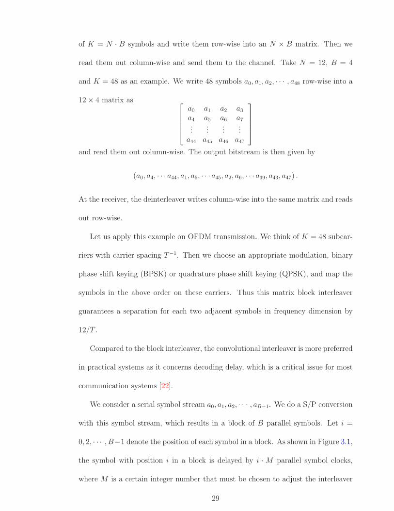
of K = N · B symbols and write them row-wise into an N × B matrix. Then we
read them out column-wise and send them to the channel. Take N = 12, B = 4
and K = 48 as an example. We write 48 symbols a0, a1, a2, · · · , a48 row-wise into a
12× 4 matrix as ⎡⎢⎢⎢⎣
a0 a1 a2 a3
a4 a5 a6 a7...
......
...a44 a45 a46 a47
⎤⎥⎥⎥⎦
and read them out column-wise. The output bitstream is then given by
(a0, a4, · · · a44, a1, a5, · · · a45, a2, a6, · · · a39, a43, a47) .
At the receiver, the deinterleaver writes column-wise into the same matrix and reads
out row-wise.
Let us apply this example on OFDM transmission. We think of K = 48 subcar-
riers with carrier spacing T−1. Then we choose an appropriate modulation, binary
phase shift keying (BPSK) or quadrature phase shift keying (QPSK), and map the
symbols in the above order on these carriers. Thus this matrix block interleaver
guarantees a separation for each two adjacent symbols in frequency dimension by
12/T .
Compared to the block interleaver, the convolutional interleaver is more preferred
in practical systems as it concerns decoding delay, which is a critical issue for most
communication systems [22].
We consider a serial symbol stream a0, a1, a2, · · · , aB−1. We do a S/P conversion
with this symbol stream, which results in a block of B parallel symbols. Let i =
0, 2, · · · , B−1 denote the position of each symbol in a block. As shown in Figure 3.1,
the symbol with position i in a block is delayed by i · M parallel symbol clocks,
where M is a certain integer number that must be chosen to adjust the interleaver
29

properties [22]. After that, the block of symbols is converted by P/S from parallel
to serial symbol stream and then transmitted.
Figure 3.1: Block diagram for the convolutional interleaver [22].
Figure 3.2: Block diagram for the convolutional deinterleaver [22].
The deinterleaver at the receiver has the same structure as the interleaver, but
the order of delay is reversed. As shown in Figure 3.2, the symbol with position
i = 0, 1, 2, · · · , B − 1 in a block is delayed by (B − i− 1) ·M parallel symbol clocks
[22].
In addition to gain diversity, interleavers are used to improve the performance of
OFDM systems by reducing the PAPR. Some methods have been proposed in the
literature, and more detail can be found in papers [51–54].
30
Please see print copy for Figure 3.1
Please see print copy for Figure 3.2
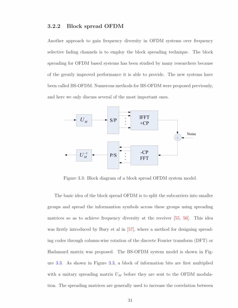
3.2.2 Block spread OFDM
Another approach to gain frequency diversity in OFDM systems over frequency
selective fading channels is to employ the block spreading technique. The block
spreading for OFDM based systems has been studied by many researchers because
of the greatly improved performance it is able to provide. The new systems have
been called BS-OFDM. Numerous methods for BS-OFDM were proposed previously,
and here we only discuss several of the most important ones.
�����������
�������
�� ��
����
Figure 3.3: Block diagram of a block spread OFDM system model.
The basic idea of the block spread OFDM is to split the subcarriers into smaller
groups and spread the informantion symbols across these groups using spreading
matrices so as to achieve frequency diversity at the receiver [55, 56]. This idea
was firstly introduced by Bury et al in [57], where a method for designing spread-
ing codes through column-wise rotation of the discrete Fourier transform (DFT) or
Hadamard matrix was proposed. The BS-OFDM system model is shown in Fig-
ure 3.3. As shown in Figure 3.3, a block of information bits are first multiplied
with a unitary spreading matrix UM before they are sent to the OFDM modula-
tion. The spreading matrices are generally used to increase the correlation between
31

the transmitted symbols in order to achieve diversity in frequency selective fading
channels. According to [57], the most common spreading matrix is the Hadamard
matrix which is defined as
U(1)M =
1√2·[
1 11 −1
], U
(n)M = U
(n−1)M ⊗ U
(1)M , (3.1)
where ⊗ denotes the Kronecker product, and the matrix size is M = 2n. Another,
less common, spreading matrix is the DFT matrix [57, 58]. A DFT matrix of order
M is defined by its elements as
Ui,k =1√M· exp(−j2π
(i− 1)(k − 1)
M), 0 < i, k ≤M. (3.2)
After the modulated data are multiplied by the Hadamard matrix or DFT matrix, a
higher order modulation scheme is created which increases the correlation between
the transmitted symbols, therefore achieving frequency diversity and better system
performance.
Based on the Hadamard matrix, the rotated Hadamard matrix is further pro-
posed. The rotated Hadamard matrix is same as the Hadmard matrix that described
above with the exception it is rotated using the rotation equation given below,
U =1√2HM×Mdiag(exp(
j × π ×m
C)) (3.3)
where HM×M is the Hadamard matrix of order M and diag denotes the diagonal
matrix [59, 60]. Here C is chosen to insure that 2πC
is the smallest angle which
rotates the signal constellation back to itself. For instance, we have C = 2b for the
signal constellation 2b-PSK (b is an integer), while for QAM constellations such as
16-QAM or 64-QAM, we have C = 4 [61]. The modulated data is multiplied by the
matrix U , where the rotation takes place to produce a higher modulation scheme
32

than traditional Hadamard. Therefore, the rotated Hadamard matrix is able to
produce a better BER performance in BS-OFDM system over Hadamard.
In addition to the above three traditional spreading matrices, a new spreading
matrix for BS-OFDM is presented by Raad and Huang. This new spreading matrix
was first proposed in [60] and number of variations and studies carried out in [59, 62–
64]. Its structure is shown as follows U = 2× 2,
U2 =
[1 tan(α)
tan(α) −1
]. (3.4)
This spreading matrix allows a system of BS-OFDM to become more flexible by
achieving different modulation schemes, say from QPSK to 64QAM. This can be
done depending on the choice of angle α. For example the choice of tan(α) = 0.5
makes QPSK into 16QAM. However, in order to yeild a better result than the
Hadamard and Rotated Hadamard matrix, not all angles can be chosen. For ex-
ample, an angle of α = π4
would result in one, which means that the matrix is a
Hadamard matrix. Other angles which cannot be used when using QPSK are α = π
and π2
since the rotation of QPSK would rotate back onto itself and the new rotation
would be the same as the rotated, that is QPSK [60, 63].
In [62], a method was proposed to expand the above new spreading matrix into
higher order spreading matrix used for BS-OFDM with larger block size, where a
higher order modulation scheme, say 64QAM for block size M = 4, can be achieved.
The structure of this higher order rotation spreading matrix can be described as
follows,
U2N =
[UN UN
UN −UN
]. (3.5)
UN = PNUNQN denotes an equivalent rotation matrix obtained by permuting
33

the rows and columns of UN . PN and QN are arbitrary monomial permutation
matrices, and have exactly one non-zero entry in every row and column, therefore
satisfying the conditions,
PNP TN = P T
NPN = QNQTN = QT
NQN = IN , (3.6)
where PN =
[0 IN
2
IN
2
0
]and QN = IN . That means UN is obtained by exchanging
the upper and lower half of UN and it was shown to have good complementary
properties.
So the 4× 4 rotation matrix U based on expansion method described above can
be shown as follows,
U4 =
⎡⎢⎢⎣
1 tan(α) tan(α) −1tan(α) −1 1 tan(α)
1 tan(α) − tan(α) 1tan(α) −1 −1 − tan(α)
⎤⎥⎥⎦ (3.7)
For a 8 × 8 rotation matrix U , the rotation spreading matrix will have following
structure, where t = tan(α)
U8 =
⎡⎢⎢⎢⎢⎢⎢⎢⎢⎢⎢⎣
1 t t −1t −1 1 t1 t −t 1t −1 −1 −t
1 t −t 1t −1 −1 −t1 t t −1t −1 1 t
1 t t −1t −1 1 t1 t −t 1t −1 −1 −t
−1 −t t −1−t 1 1 t−1 −t −t 1−t 1 −1 −t
⎤⎥⎥⎥⎥⎥⎥⎥⎥⎥⎥⎦
. (3.8)
Higher order M ×M rotation spreading matrices can be achieved when the method
described in Eq. 3.5 is used. This ensures that the higher order matrix maintains
orthogonality for a larger block size.
3.3 Multiple-antenna techniques
The use of multiple antennas has become one of the most promising areas in recent
wireless communications. When multiple antennas are used at both transmitters and
34

receivers, as shown in Figure 3.4, it is generally referred to as the MIMO system.
The focus of MIMO systems is that the signals on the transmit antennas at one
end and the receive antennas at the other end are combined in such a way that the
quality (bit error rate) or the data rate of the communication for each user will be
improved [65]. The most amazing advantage of MIMO systems is the ability to turn
multipath propagation, traditionally a negative effect for wireless transmission, into
a benefit for the user.
This section begins with an overview of MIMO systems, which introduces the
basic idea of developing MIMO techniques, and highlights the unique benefits that
MIMO can offer. Next, we look at the practical design of MIMO systems that in-
volves the development of transmission signal processing algorithms, where different
space time coding schemes are applied. We conclude with a discussion of an effec-
tive combination between OFDM and MIMO techniques, which brings a significant
beneifts and may play a critical role in future wireless communications.
��� ��������� ��
�� ��� ������ ��
�� ��� �������� ����������� ������� ��
������� �!����
�������
Figure 3.4: Diagram of a MIMO wireless transmission system.
3.3.1 Overview of MIMO systems
The phenomenon of time-varying multipath fading is a key factor that makes wire-
less transmission a challenge when compared to fiber, cable, microwave or even
statellite transmissions. Increasing the quality or reducing the BER in a multipath
fading channel is extremely difficult [66]. For instance, in additive white Gaussian
35

noise (AWGN), reducing the BER from 10−2 to 10−3 may require only 1 or 2 dB
higher signal-to-noise ratio (SNR) by using specific modulation and coding schemes.
Achieving the same BER reduction in a multipath fading environment, however,
may require up to 10 dB improvement in SNR [66].
There are several techniques that can be used to mitigate multipath fading in a
wireless channel. Theoretically, the most effective one is transmitter power control
[66]. But there are two fundamental problems with this approach. The major
problem is the required dynamic power change at the transmitter, which in most
cases is impractical. The second problem is that the channel information has to be
fed back from the receiver to the transmitter, which results in considerable additional
complexity to both the transmitter and the receiver. Another effective technique
is antenna diversity, which has been widely applied in most scattering environment
for reducing the effect of multipah fading [67]. The common approach is to install
multiple antennas at the receiver to perform combining and switching in order to
improve the quality of the received signal. Recently multiple antennas have been
exclusively equipped to base stations to improve their reception quality as a base
station often covers hundreds to thousands of square kilometers, which is more
economical than adding multiple antennas at the remote units. Some interesting
approaches for antenna diversity have been suggested. A delay diversity scheme was
proposed by Wittneben [68, 69] and a similar scheme was suggested by Seshadri
and Winters [70, 71] for a base station in which copies of the same symbol are
transmitted through multiple antennas at different times, resulting in an artifical
multipath distortion. A maximum likelihood (ML) sequence estimator or a MMSE
equalizer is then used to resolve multipath distortion and obtain diversity gain.
36

Another interesting approach is space-time trellis coding (STTC), discussed in
[72–75], where modulation and trellis coding are combined to transmit signals over
multiple transmit antennas and multipath channels. This scheme is effective since
it combines the benefits of trellis-coded modulation (TCM) [72] and diversity trans-
mission to achieve a higher coding gain and better performance. In addition to
obtain diversity gains, however, low complexity encoding and decoding is crucial for
MIMO systems as higher complexity consumes more battery power, which is lim-
ited for recent mobile units. Due to the fact that the complexity of STTC increases
exponentially as high diversity order is required, it is not cost-effective for some
applications and becomes less popular especially when another scheme, so-called
space-time block coding (STBC), is developed. In contrast to the complex decoding
algorithm for STTC, STBC can be decoded using simple linear processing at the
receiver and meanwhile gives the same diversity gain as the STTC for the same
number of TX antennas. As a result, below, we will mainly focus our attention on
the design of STBC rather than on trellis-based approaches. As the reader should
note, in spite of the difference between STTC and STBC, both of them belong to
the STC scheme, where the multiple antennas are only used as a source of spatial
diversity and not to increase data rate.
3.3.2 Model of STBC-MIMO systems
As introduced above, the decoding complexity of STTC increases exponentially with
the diversity level and transmission rate [74]. In addressing this issue of decoding
complexity, Alamouti [66] frist proposed the idea of STBC for transmission with
two antennas, which improves the transmit diversity at the receiver by only using
37

a simple linear processing scheme. The simple structure and linear processing of
the Alamouti construction make STBC a very attractive scheme that is currently
applied on both the W-CDMA and CDMA-2000 standards [65]. This scheme was
later generalized in [76] to an arbitrary number of antennas. Next we will briefly
discuss the basics of STBC by exploiting a simple example.
Figure 3.5 shows the baseband modelling for Alamouti STBC with two anten-
nas at the transmitter. Before STBC encoder, a modulation scheme is used to
map information bits to symbols from a constellation. The constellation can be
any real or complex constellation, for example, PSK, QAM, and so on. The input
symbols to the STBC encoder are then divided into groups of two symbols. At a
given symbol period, the two symbols in each group [c1, c2] are transmitted simul-
taneously from the two antennas. The signal transmitted from antenna 1 is c1 and
the signaltransmitted from antenna 2 is c2. In the next symbol period, the signal
−c∗2 is transmitted from antenna 1 and the signal c∗1 is transmitted from antenna 2.
Therefore, the transmitted codeword is
C =
[c1 −c∗2c2 c∗1
]. (3.9)
���������� �� �����
��"�
� ������
� �����#� � � #� #
# �
� �� �
� �
�
�
� ���
� ���$����� ��% ��
Figure 3.5: Transmitter block diagram for Alamouti STBC.
For the design of the receiver end, we assume that a single RX antenna is used.
38

Let h1 and h2 be the channels from the first and second TX antennas to the RX
antenna, respectively. The major assumption here is that h1 and h2 are scalar and
constant over two consecutive symbol periods, that is
hi(2nT ) = hi((2n + 1)T ), i = 1, 2. (3.10)
We denote the received signal over two consecutive symbol periods as r1 and r2.
The received signals then can be expressed as
r1 = h1c1 + h2c2 + n1 (3.11)
r2 = −h1c∗2 + h2c
∗1 + n2 (3.12)
where n1 and n2 represent the AWGN and are modeled as i.i.d. complex Gaussian
random variables with zero mean and power spectral density N0/2 per dimension.
For simplicity of expression, we define the received signal vector r = [r1 r∗2]T , the
code symbol vector c = [c1 c2]T , and the noise vector n = [n1 n∗2]
T . Thus, equations
3.11 and 3.12 can be written in a matrix form as
r = H · c + n (3.13)
where the channel matrix H is defined as
H =
[h1 h2
h∗2 −h∗1
]. (3.14)
H is now a virtual MIMO matrix with space (columns) and time (rows) dimensions.
It is realized that the channel matrix H is always orthogonal regardless of the channel
coefficients, which means H∗ · H = α · I2 where α = |h1|2 + |h2|2. Hence, the
equation 3.13 can be further modified as follows
r = H∗ · r = α · c + n (3.15)
39

where n = H∗ · n, which is a complex Gaussian random vector with zero mean and
covariance αN0 · I2. Therefore, in this case, the optimum ML decoding rule is
c = arg minc∈c
‖r− α · c‖2 . (3.16)
It is obvious that for the above 2× 1 STBC, only two complex multiplications and
one complex addition per symbol are required for decoding. It is also straightforward
to verify that the SNR for c1 and c2 will be
SNR =α · Es
N0
(3.17)
and hence, a diversity gain of order two is obtained at the receiver. Figure 3.6 shows
a simplified block diagram of STBC receiver with one RX antenna.
& ��������% ��� &
'�� � ��� �(
# #
� ��
� ��� � � �
� � � �
��
� �� #�� �� � � �� #) ) �� �
� �� #� �
Figure 3.6: Receiver block diagram for Alamouti STBC.
Though the simple Alamouti STBC scheme, as described above, was initially
developed to provide transmit diversity in the multiple-input-single-output (MISO)
case, it is readily extended to the MIMO case when the receiver uses multiple RX
antennas. The extension of the STBC to more than one RX antenna was later
studied in many literatures, and see [77–79] for details.
3.3.3 OFDM with MIMO systems
The space-time coding was originally designed for a narrowband wireless system,
where only a flat fading channel is experienced. Different from the flat fading chan-
40

nel, the large delay spreads in frequency selective fading channels destroy the orthog-
onality of the received signal, which is crucial for STC to gain diversity. Therefore,
when used over frequency selective fading channels a complex equalization method is
required at the receiver along with the space-time decoder. However, the nonlinear
and noncausal nature of the space-time code makes the use of traditional equaliza-
tion methods, such as MMSE linear equalizer, decision feedback equalizer (DFE),
and MLSE, a challenging problem.
OFDM, as described in Chapter 2, is an effective technique for eliminating or at
least mitigating the effects of delay spreads in frequency selective fading channels.
According to [80], by using OFDM modulation, frequency selective fading channels
can be transformed into multiple flat fading channels, thereby the space-time coding
method can be effectively applied to improve system performance, even over chan-
nels with large delay spreads. Hence, the OFDM based MIMO system effecitvely
resolves the equalization complexity problem and extends the utilization of space-
time coding into frequency selective fading channels. Due to the great advantage of
the combination between OFDM and STC, numerous investigations have been made
on this topic and various MIMO-OFDM schemes have appeared in previous work,
such as [81–84]. As following, we only presents a simple example to demonstrate
the scheme that combines the Alamouti STBC with OFDM.
In the present example, we implement Alamouti’s transmit diversity scheme in
time direction on each subcarrier for a pair of subsequent OFDM symbols. Let
sl[k] = slk denote the complex PSK or QAM symbols with time index l = 1, 2 and
frequency index k = 1, · · · , N , N is the total number of OFDM subcarriers. For each
frequency index k, the symbols will be multiplexed to the two transmit antennas
41
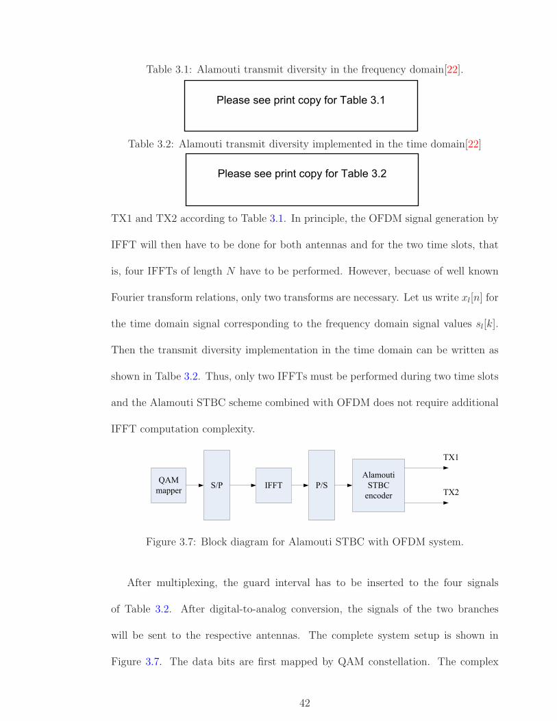
Table 3.1: Alamouti transmit diversity in the frequency domain[22].
Table 3.2: Alamouti transmit diversity implemented in the time domain[22]
TX1 and TX2 according to Table 3.1. In principle, the OFDM signal generation by
IFFT will then have to be done for both antennas and for the two time slots, that
is, four IFFTs of length N have to be performed. However, becuase of well known
Fourier transform relations, only two transforms are necessary. Let us write xl[n] for
the time domain signal corresponding to the frequency domain signal values sl[k].
Then the transmit diversity implementation in the time domain can be written as
shown in Talbe 3.2. Thus, only two IFFTs must be performed during two time slots
and the Alamouti STBC scheme combined with OFDM does not require additional
IFFT computation complexity.
*+ ������ �� ����
+������ ��"��������
��
���
��#
Figure 3.7: Block diagram for Alamouti STBC with OFDM system.
After multiplexing, the guard interval has to be inserted to the four signals
of Table 3.2. After digital-to-analog conversion, the signals of the two branches
will be sent to the respective antennas. The complete system setup is shown in
Figure 3.7. The data bits are first mapped by QAM constellation. The complex
42
Please see print copy for Table 3.1
Please see print copy for Table 3.2

QAM symbols are then processed blockwise by an IFFT device of FFT length N ,
resulting in a stream of complex time domain samples that are grouped into vectors
xi[n], n = 0, 1, · · · , N − 1 of length N , each corresponding to one OFDM symbol
numbered by i. These vectors are grouped into pairs, and each pair is processed by
the Alamouti STBC encoder according to Table 3.2. After this, the guard interval
is inserted separately to the resulting OFDM symbols for the respective antennas.
The above example briefly summarizes the approach that the Alamouti STBC
is applied to two OFDM consecutive subcarriers. In previous work, the Alamouti
STBC shceme is imposed on a block basis rather than the original scheme that a
symbol basis is emphasized. Several approaches were proposed in [85–87], where
the Alamouti STBC is applied to two OFDM consecutive block vectors in the time
domain or frequency domain.
3.4 Chapter summary
In this chapter, we first describe several drawbacks of conventional OFDM systems.
OFDM systems may experience a large distortion due to nonlinearity as a result of
high PAPR. OFDM systems are also sensitive to frequency synchronization. Since
subcarriers in OFDM systems are densely overlapped because of orthogonality, sys-
tems may suffer from serious ICI when frequency synchronization errors occur. Lack
of frequency diversity is another common disadvantage of OFDM systems, which re-
sults in a poor performance especially on transmission over frequency selective fading
channels.
Achieving diversity for OFDM systems has become attractive and has received
much attention in recent research. The core idea of diversity gain is to combat the
43

effect of frequency selective fading channels, thus improving system performance.
There are many methods proposed in previous work to provide diversity for OFDM
systems. The time and frequency interleaving is one of them. We introduce the in-
terleaving method with an emphasis on two basic interleavers: block interleaver and
convolutional interleaver. Another approach to gain diversity in OFDM systems is
block spreading. The main idea of block spreading with OFDM is to use spreading
matrices to spread symbols accross subcarriers, and as a result the frequency diver-
sity is obtained. We introduce several spreading matrices that are well developed
by previous researchers, such as the DFT matrix, the Hadamard matrix, and the
rotated spreading matrix, etc.
The MIMO scheme is another important technique for OFDM systems. The
most significant property of MIMO is its ability to achieve spatial diversity by tak-
ing advantage of multipath propagation, which has traditionally been an impairment
in wireless transmission systems. There are many approaches to implement MIMO,
but here we mainly focus on the the STBC-MIMO. We present an example model
of STBC-OFDM systems with two transmitters and one receiver, and accordingly,
algorithms for coding and decoding are described as well. The MIMO-OFDM sys-
tems have received considerable attention as a suitable candidate for next generation
wireless communications.
44

Chapter 4Block spread OFDMA system with
STC-MIMO
In this project, we propose a block spread orthogonal frequency division multiple
access (BS-OFDMA) system with a combined STC-MIMO scheme for transmission
over frequency selective fading channels. We refer to the system as a STC-MIMO BS-
OFDMA system. In this system, first, a novel approach is developed to effectively
combine the block spreading technique and OFDMA modulation to obtain improved
bit error performance and greatly lower system complexity. The STC-MIMO encod-
ing is then skillfully incorporated to take advantage of multipath channels, resulting
in a spatial diversity achieved for the proposed system.
In this chapter, we first explore the basic idea of the proposed system and de-
scribe its resultant novel contributions in order to distinguish from other similar
systems presented in the literature. Next, a transmitter model for our proposed
system is given in detail, including the implementation of block spreading, OFDMA
modulation and STC-MIMO encoding. A corresponding receiver model and de-
coding algorithms are then presented. We use linear channel equalization which is
simpler in practice. Finally, simulations are carried out to confirm the expected
45

performance improvement by a comparison with an existing OFDMA system with
or without block spreading.
4.1 Overview of the proposed system
As we have learnt from Chapter 3, the combination of block spreading technique
with the OFDM systems can offer significant system improvement by achieving
frequency diversity over frequency selective channels at the cost of more compli-
cated transmitter and receiver structures. On the other hand, MIMO systems have
received considerable attention as MIMO effectively takes advantage of multipath
channels. Such an advantage can be used to greatly increase the quality of service
for wireless communications systems. The STC is one of prominent canditates of
MIMO encoding design that can be used in conjunction with OFDM.
In this project, we aim to extend the idea of block spread OFDM and STC-
MIMO to a combined STC-MIMO BS-OFDMA system for multiuser application. In
a conventional OFDMA system, each user transmits an OFDM signal over a number
of subcarriers. Each subcarrier represents a narrowband signal and is orthogonal to
other subcarriers assigned to the same user as well as other users. Therefore, the
transmitted signals from different users reside in different frequency bands which are
much narrower than the total available system bandwidth, and experience different
channel fading effects. In our proposed BS-OFDMA scheme, however, the block
spread signal is no longer a narrowband signal but spreads over all frequency band
allocated for the system. All users share the same bandwidth even though they have
complex exponentials with different discrete frequencies. Moreover, the transmitted
information bits are combined and spread across the whole frequency band where
46

variety of channel fadings occur. The frequency diversity is therefore achieved. As
a result, the BS-OFDMA scheme will offer much better performance over frequency
selective fading channels than conventional OFDMA systems.
In contrast to other block spreading techniques with OFDM, the proposed system
has much simpler structures for the transmitter and reciever design. According
to[58, 59, 61], at the transmitter, the combination of block spreading with OFDM is
usually implemented by a precoding process of assigning a spreading matrix followed
by the IFFT; and then both a de-precoding process to remove the spreading matrix
and FFT are required at the receiver. In our system, however, we discard both
the precoding for block spreading and the IFFT modulation. Instead we use a
complex exponential sequence to effectively implement BS-OFDMA scheme, thus
greatly reducing the system complexity particularly for the transmitter end.
The STC-MIMO using Alamouti code is further applied to gain an additional
diversity. The encoding is theoretically performed in space and frequency, however,
it is actually done in space and time to effectively incorporate with the previous block
spread OFDMA modulation. Instead of the symbol basis, the Alamouti scheme
is imposed on a block basis because after block spreading, symbols are no longer
independently taken by each subcarrier but spread over all frequency band allocated
to the system.
The relevant receiver and decoding algorithms are developed for block despread-
ing, MIMO decoding and channel equalization. Since the ML detection is highly
computationally complicated, especially when the block size is large, a linear equal-
ization, such as the MMSE equalization and the ZF equalization, followed by a hard
decision is preferable. Here we choose the MMSE equalization as it offers a trade-
47

off between the high complexity of ML detection and the poor performance of ZF
equalization. At last, performance evaluation and comparisons are conducted to
demonstrate the anticipated improvement.
The novel contributions of this project therefore include 1) the application of
a new scheme to effectively combine the block spreading technique with OFDMA
modulation to obtain improved performance and greatly reduce system complexity
as well; 2) the implementation of STC-MIMO using Alamouti code in the frequency
domain to gain multipath diversity over frequency selective fading channels; 3) the
design of MMSE equalization as a decoding method for the proposed block spread
STC-MIMO OFDMA system.
4.2 Signal model for transmitter
In this section, the structure of the block spread STC-MIMO OFDMA transmitter
is shown in Figure 4.1. We first explore the method that effectively combines block
spread with OFDMA without using any spreading matrices and IFFT processors.
The output signals from BS-OFDMA module are then encoded by the STC-MIMO
encoder to implement the Alamouti code in the frequency domain.
4.2.1 BS-OFDMA design
As shown in Figure 4.1, we group two vectors x1 and x2, where x1 = (x1[0], · · · , x1[M−
1]) and x2 = (x2[0], · · · , x2[M − 1]) are two consecutive block modulated symbol
vectors after a Quadrature Phase Shift Keying (QPSK) modulation. The length of
each symbol vector is M , which is an integer power of 2. The symbol vector x1
and x2 are first sent to a block extension module, where each vector is extended to
MN length by simply duplicating itself for N times. Then a complex exponential
48

, -��
, -��
Figure 4.1: Block spread STC-MIMO OFDMA transmitter model.
sequence cK [n] is assigned to those extended vectors to implement block spreading.
It is expressed as
cK [n] = exp(j2πKn
N), n = 0, 1, · · · , N − 1, K = 0, 1, · · · , N − 1, (4.1)
where K is the user index to identify a specific user and N denotes the number
of users in the system. In addition to block spreading, cK [n] is also used to gen-
erate OFDMA signals as it constitues a set of orthogonal functions with each user
differentiated by a distinct frequency. Therefore, the block spreading technique
and OFDMA modulation are effectively combined in our system without any ad-
ditional precoding processes and IFFT application, and thus the system compu-
tational complexity is greatly reduced. The elements of the output symbol vector
y1 = (y1[0], · · · , y1[MN−1]) and y2 = (y2[0], · · · , y2[MN−1]) after the block spread
OFDMA modulation are expressed as
y1[i] = x1[m]cK [n]y2[i] = x2[m]cK [n]i = nM + m,m = 0, 1, · · · ,M − 1, n = 0, 1, · · · , N − 1.
(4.2)
49

Rather than the mathematical expression, this process can also be illustrated in
Figure 4.2, which is much more straightforward to explain the approach of using the
proposed sequence to implement BS-OFDMA modulation.
, �-�� �,�-��,.-��
"���/��������0�' +12���� ��
� #
� #
� #
Figure 4.2: Process of BS-OFDMA implementation.
The most siginficant advantage of BS-OFDMA is that it is able to improve
system performance by achieving frequency diversity to combat frequency selective
fading channels. This can be easily derived by investigating the signal model in the
frequency domain. After performing a MN -point DFT of yt[i], t = 1 or 2, we can
find out
Yt[k] =MN−1∑
i=0
yt[i]e−j 2π
MNki
i=nM+m=
N−1∑n=0
M−1∑m=0
yt[nM + m]e−j 2π
Nkne−j 2π
MNkm
=N−1∑n=0
M−1∑m=0
xt[m]cK [n]e−j 2π
Nkne−j 2π
MNkm
=N−1∑n=0
M−1∑m=0
xt[m]ej 2πK
Nne−j 2π
Nkne−j 2π
MNkm
=M−1∑m=0
xt[m]e−j 2π
MNkm
N−1∑n=0
e−j 2π
N(k−K)n
=
{XK,t[l], k = lN + K, l = 0, 1, · · · ,M − 10, otherwise
(4.3)
50

where
XK,t[l] = NM−1∑m=0
xt[m]e−j 2π
MN(lN+K)m,
l = 0, 1, · · · ,M − 1.(4.4)
For simplicity of the expression, we create a vector Yt that only contains nonzero
elements of Yt[k]. It is expressed as Yt = (Yt[K], Yt[N +K], · · · , Yt[(M −1)N +K]).
Therefore, we can write a new equation as
Yt = NxtWM , (4.5)
where
WM =
⎡⎢⎢⎢⎣
eαK×0 eα(K+N)×0 · · · eα[K+(M−1)N ]×0
eαK×1 eα(K+N)×1 · · · eα[K+(M−1)N ]×1
......
. . ....
eαK×(M−1) eα(K+N)×(M−1) · · · eα[K+(M−1)N ]×(M−1)
⎤⎥⎥⎥⎦ (4.6)
denotes the phase rotation matrix with order M and α = −j 2πMN
. Eq. 4.3 and Eq. 4.5
imply that, through the block spread OFDMA modulation, the M data symbols for
the Kth user are mixed via phase rotation and then spread across M equally spaced
subcarriers.
Figure 4.3: Block spread OFDMA signal model in the frequency domain.
An example of the OFDMA signal model in the frequency domain after block
spreading is illustrated in Figure 4.3, where the number of users is N = 4 and
each user carries M = 8 data symbols. As indicated in Figure 4.3, multiple users
can share the same frequency channel like other multiple access systems (CDMA or
51

OFDMA). The receiver can extract any user’s data signal without interference from
any other user after performing correlation with the complex exponential sequence
assigned to the user. However, in contrast to conventional OFDMA system without
block spreading, each subcarrier for a specific user in the block spreading OFDMA
system no longer takes a single data symbol but a set of all data symbols combined
together. Therefore, the frequency diversity is achieved, and a significant improved
performance over frequency selective fading channels is thus expected.
4.2.2 STC-MIMO encoding
We consider two transmit antennas for the STC-MIMO design following the BS-
OFDMA module. We propose an approach that applies the Alamouti code in the
frequency domain to implement space-time encoding. It is different from the STC-
MIMO described in Chapter 3, where the Alamouti code is applied to the time
domain. However, based on the conjugation property of Fourier transform relations
between time domain and frequency domain, the STC-MIMO encoding is actually
performed in the time domain in our system so that the block spreading can be
easily incorporated. This process is shown in Figure 4.4.
Figure 4.4: Process in the time domain to implement STC-MIMO.
52

Table 4.1: STC-MIMO in the time domain
Antenna TX1 TX2Time slot 1 y1 y2
Time slot 2 −(y2)∗ (y1)
∗
Table 4.2: STC-MIMO in the frequency domain
Antenna TX1 TX2Time slot 1 Y1 Y2
Time slot 2 −Y∗2 Y∗
1
In order to obtain a conjugation of the signal in the frequency domain, we main-
tain the first symbol and reverse the remaining symbols of the input vectors y1
and y2 respectively to generate y1 and y2 in the time domain. Theoretically, this
is equivalent to periodically extending y1 and y2, then reversing all symbols and
taking one period. At given time slot, y1 is transmitted from transmitter one and
y2 is transmitted from transmitter two. During the next time slot, −(y2)∗ and (y1)
∗
are transmitted from transmitter one and two, respectively, where ∗ denotes the
complex conjugation. As a result, the Alamouti code can be accordingly realized in
the frequency domain. Table 4.1 and Table 4.2 show the relationship between the
STC-MIMO encoding in the time domain and the frequency domain.
To deal with the effect of multipath channels between transmitters and receivers,
a CP of length L, which is a copy of the last L symbols of each STC-MIMO BS-
OFDMA vector, will be added in front of that vector before transmission. The
length of CP should be longer than the maximum channel multipath delay spread
in order to turn the linear convolution of the transmitted signal with the channel
impulse response into a circular one. Thus, the transmitted signal block has MN +L
symbols in total after CP is added.
53

4.3 Signal model for receiver
For simplicity, we consider a structure with one receive antenna to explain the
receiver algorithms for STC-MIMO decoding, block despreading and channel equal-
ization in detail. In order to achieve a higher order of diversity, we extend the
reciever structure to the case of two receive antennas. In such a case, it attempts
to double the diversity order by simply adding an extra antenna, and thus a further
performance improvement is obtained.
4.3.1 MIMO channel model for one receiver
Figure 4.5 shows the baseband representation of the block spread STC-MIMO
OFDMA receiver structure with one antenna. The received signals are first trans-
formed from the time domain to the frequency domain, which is done by an FFT
processing. It is much more insightful to consider the decoding process in the fre-
quency domain, although the time domain model is straightforward. The frequency
domain signals are then sent to the STC-MIMO decoder, where a decoding algorithm
is developed for one receiver.
� #
Figure 4.5: Block spread STC-MIMO OFDMA receiver model with one antenna.
Let H1[k] and H2[k] be the channel frequency responses for the k-th subcarrier
corresponding to two transmitters and one reciever. We assume that those channel
54

responses are constant during periods of two consecutive block data vectors and
known to the receiver. After removing the CP, the MN -point FFT and N factor
down-sampling are implemented to generate frequency domain signals. Thus, the
received signals in the frequency domain can be expressed by R1[k] and R2[k], k =
0, 1, · · · ,M − 1, as
R1[k] = Y1[k]H1[k] + Y2[k]H2[k] + V1[k] (4.7)
R2[k] = −Y ∗2 [k]H1[k] + Y ∗
1 [k]H2[k] + V2[k], (4.8)
where V1[k] and V2[k] are noise samples for k-th subcarrier on each channel that can
be modeled as complex Gaussian random variables with zero mean and power N0/2
per dimension. To group the received symbols to be a vector format, the above
equations can be equivalently expressed as follows,
R1 = Y1H1 + Y2H2 + V1 (4.9)
R2 = −Y∗2H1 + Y∗
1H2 + V2, (4.10)
where we denote
R1 = (R1[0], R1[1], · · · , R1[M − 1]) ,R2 = (R2[0], R2[1], · · · , R2[M − 1]) ,Y1 = (Y1[0], Y1[1], · · · , Y1[M − 1]) ,Y2 = (Y2[0], Y2[1], · · · , Y2[M − 1]) ,H1 = diag(H1[0], H1[1], · · · , H1[M − 1]),H2 = diag(H2[0], H2[1], · · · , H2[M − 1]),V1 = (V1[0], V1[1], · · · , V1[M − 1]) ,V2 = (V2[0], V2[1], · · · , V2[M − 1]) .
(4.11)
Note that H1 and H2 are M ×M matrices with diagonal elements decimated from
the channel discrete frequency responses H1[k], and H2[k], k = 0, 1, · · · ,M − 1,
respectively.
For simplicity of expression, we define R = (R1, R∗2), Y = (Y1, Y2), H =(
H1 H∗2
H2 −H∗1
)and V = (V1, V∗
2). Thus, Eq. 4.9 and Eq. 4.10 can be rewritten in
55

a matrix form as
R = YH + V. (4.12)
4.3.2 MIMO channel model for two receivers
The receiver model can be easily generalized to multiple receive antennas to provide
a higher order of diversity. For illustration, we discuss an another example in detail,
where the receiver is equipped with two antennas. Figure 4.6 shows the baseband
representation of the receiver with two antennas.
Figure 4.6: Block spread STC-MIMO OFDMA receiver model with two antenna.
The transmitter structure and encoding algorithms of the information symbols
for this example is identical to the case of a single receiver, shown in Figure 4.1.
Instead of two channels in the single receiver, we have four independent channels
corresponding to two transmitter and two receiver. Table 4.3 defines the channel
frequency responses at k-th subcarrier between the transmit and receive antennas.
Table 4.4 defines the notation of the received signals at the k-th subcarrier in the
frequency domain at the two receive antennas.
Like the channel model for one receiver, the same assumption is made to two
receivers that channel responses are constant during periods of two consecutive sym-
bol vectors and known to the receivers. Therefore, the received signals are similarly
56

Table 4.3: Channels between the transmit and receive antennas
RX antenna1 RX antenna2TX antenna1 H1[k] H3[k]TX antenna2 H2[k] H4[k]
Table 4.4: Received signals at the two receive antennas
RX antenna1 RX antenna2Time slot 1 R1[k] R3[k]Time slot 2 R2[k] R4[k]
expressed asR1[k] = Y1[k]H1[k] + Y2[k]H2[k] + V1[k]R2[k] = −Y ∗
2 [k]H1[k] + Y ∗1 [k]H2[k] + V2[k]
R3[k] = Y1[k]H3[k] + Y2[k]H4[k] + V3[k]R4[k] = −Y ∗
2 [k]H3[k] + Y ∗1 [k]H4[k] + V4[k]
k = 0, 1, · · · ,M − 1,
(4.13)
where V1[k], V2[k], V3[k] and V4[k] are complex Gaussian random variables repre-
senting noise samples for k-th subcarrier on each channel. For clearness, the above
equation can be transformed to a vector expression as
R1 = Y1H1 + Y2H2 + V1
R2 = −Y∗2H1 + Y∗
1H2 + V2
R3 = Y1H3 + Y2H4 + V3
R4 = −Y∗2H3 + Y∗
1H4 + V4
(4.14)
if we denoteR1 = (R1[0], R1[1], · · · , R1[M − 1]) ,R2 = (R2[0], R2[1], · · · , R2[M − 1]) ,R3 = (R3[0], R3[1], · · · , R3[M − 1]) ,R4 = (R4[0], R4[1], · · · , R4[M − 1]) ,Y1 = (Y1[0], Y1[1], · · · , Y1[M − 1]) ,Y2 = (Y2[0], Y2[1], · · · , Y2[M − 1]) ,H1 = diag(H1[0], H1[1], · · · , H1[M − 1]),H2 = diag(H2[0], H2[1], · · · , H2[M − 1]),H3 = diag(H3[0], H3[1], · · · , H3[M − 1]),H4 = diag(H4[0], H4[1], · · · , H4[M − 1]),V1 = (V1[0], V1[1], · · · , V1[M − 1]) ,V2 = (V2[0], V2[1], · · · , V2[M − 1]) ,V3 = (V3[0], V3[1], · · · , V3[M − 1]) ,V4 = (V4[0], V4[1], · · · , V4[M − 1]) .
(4.15)
Similarly, in order to derive a general expression, we can further define R = (R1,
R∗2, R3, R∗
4), Y = (Y1, Y2), H =
(H1 H∗
2 H3 H∗4
H2 −H∗1 H4 −H∗
3
)and V = (V1, V∗
2,
57
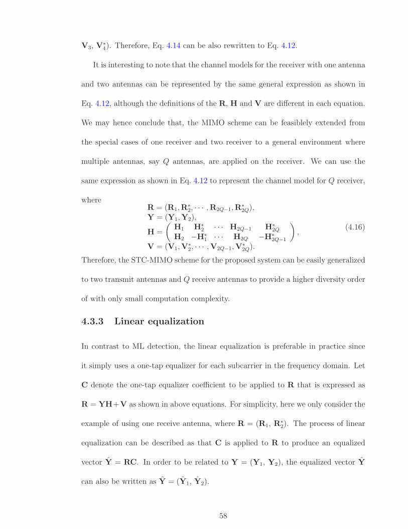
V3, V∗4). Therefore, Eq. 4.14 can be also rewritten to Eq. 4.12.
It is interesting to note that the channel models for the receiver with one antenna
and two antennas can be represented by the same general expression as shown in
Eq. 4.12, although the definitions of the R, H and V are different in each equation.
We may hence conclude that, the MIMO scheme can be feasiblely extended from
the special cases of one receiver and two receiver to a general environment where
multiple antennas, say Q antennas, are applied on the receiver. We can use the
same expression as shown in Eq. 4.12 to represent the channel model for Q receiver,
whereR = (R1,R
∗2, · · · ,R2Q−1,R
∗2Q),
Y = (Y1,Y2),
H =
(H1 H∗
2 · · · H2Q−1 H∗2Q
H2 −H∗1 · · · H2Q −H∗
2Q−1
),
V = (V1,V∗2, · · · ,V2Q−1,V
∗2Q).
(4.16)
Therefore, the STC-MIMO scheme for the proposed system can be easily generalized
to two transmit antennas and Q receive antennas to provide a higher diversity order
of with only small computation complexity.
4.3.3 Linear equalization
In contrast to ML detection, the linear equalization is preferable in practice since
it simply uses a one-tap equalizer for each subcarrier in the frequency domain. Let
C denote the one-tap equalizer coefficient to be applied to R that is expressed as
R = YH+V as shown in above equations. For simplicity, here we only consider the
example of using one receive antenna, where R = (R1, R∗2). The process of linear
equalization can be described as that C is applied to R to produce an equalized
vector Y = RC. In order to be related to Y = (Y1, Y2), the equalized vector Y
can also be written as Y = (Y1, Y2).
58

When the MMSE criterion is used to design C, the mean squared error (MSE)
between Y and Y that ban be expressed as
ε2 = E{
(Y −Y)†(Y −Y)}
(4.17)
is minimized, where (·)† denotes the matrix transposition and complex conjugation
operation. Since Y = RC, the MSE express in 4.17 can be rewritten as
ε2 = E{(RC−Y)†(RC−Y)
}. (4.18)
Applying the orthogonality principle, we have
E{(RC−Y)R†
}= 0 (4.19)
and consequently,
C = E{YR†
}(E
{RR†
})−1. (4.20)
Substituting Eq. 4.12 into Eq. 4.20, the C can be consequently derived as
C = E{Y(YH + V)†}(E{(YH + V)(YH + V)†})−1
= E{YY†}H†(HE{YY†}H† + E{VV†})−1
= H†(HH† + 1
γin
I)−1
,
(4.21)
where I is the identity matrix with the same size of H, and γin is the input SNR
before equalization.
As seen from Eq. 4.21, the MMSE equalization requires the knowledge of the
input SNR. If this knowledge is not available, ZF equalization can be performed by
assuming no noise is present at the receiver and selecting the equalizer coefficients
to force the ISI to zero. Hence, for ZF equalization, the equalizer coefficient can be
expressed as
C = H†(HH†
)−1. (4.22)
59

However, pure ZF equalization enhances noise power when the input SNR is low
and causes dividing-by-zero problem at null subcarriers. In practice, we can design
a general expression of the linear equalizer coefficient C according to an estimated
reference SNR γref as
C = H†
(HH† +
1
γref
I
)−1
. (4.23)
Apparently, if γref = γin this linear equalization becomes the MMSE equalization,
and as γref →∞ it becomes the ZF equalization.
Therefore, according to above analysis, the output signal vector after the MIMO
detection and linear equalization becomes Y = RC = (Y1, Y2). It is then sent to
the following module, where the block despreading is performed to yield the decision
variable vector d = (d1, d2) and finally the estimated data symbol vector x = (x1,
x2) can be retrieved after hard decision on the decision variable vector.
4.3.4 Block despreading
The process of block despreading includes three steps that are described as follows.
First, the MN -point DFT is performed to transform the received signals rt, t = 1
or 2 from time domain to frequency domain. Second, a N factor down-sampling is
applied on the MN length frequency domain signals yeild baseband signals Rt with
length of M . The above two steps are done at the beginning of the receiver. Finally,
after the MIMO detection and linear equalization to remove the effect of multipath
channels, a despreading matrix is assigned to recover the transmitted data symbol
vector xt from the spreading vector Yt, where data symbols are block coded and
spread across the subcarriers.
According to the frequency domain characteristics of the transmitted BS-OFDMA
60

signal shown in Figure 4.3, the M data symbols for each specific user are mixed and
spread over whole system frequency band of MN length, where N is the total num-
ber of users in the system. In spite of the symbol spreading characteristic, we first
take account of the bandwidth usage in the system. Rather than dividing the wide
frequency band into a serial of narrowbands and separately assigning those narrow-
bands to each user, the frequency band in the proposed system is shared by all users.
In other words, the data symbols for each user in the system are interleaved across
equally spaced subcarriers. Since the total length of the system frequency band is
MN and each user only occupies the M equally spaced subcarriers, the MN -point
DFT and N factor down-sampling are required to yield the baseband signals with
length of M corresponding to a specific user.
We assume that Rt[k], k = 0, 1, · · · ,MN − 1 represents the output of the MN -
point DFT of received signals rt[i], i = 0, 1, · · · ,MN − 1. As shown in Figure 4.7,
the N factor down-sampling of Rt[k] is based on the user index K and implemented
starting from Rt[K], where K = 0, 1, · · · , N−1. Note that the MN -point DFT and
N factor down-sampling are done at the beginning of the receiver in order to reduce
the computation complexity for the following system decoding processes.
Figure 4.7: The N factor down-sampling for a specific user with index K.
61
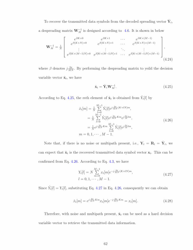
To recover the transmitted data symbols from the decoded spreading vector Yt,
a despreading matrix W−1M is designed according to 4.6. It is shown in below
W−1M = 1
N
⎡⎢⎢⎢⎣
eβK×0 eβK×1 · · · eβK×(M−1)
eβ(K+N)×0 eβ(K+N)×1 · · · eβ(K+N)×(M−1)
......
. . ....
eβ[K+(M−1)N ]×0 eβ[K+(M−1)N ]×1 · · · eβ[K+(M−1)N ]×(M−1)
⎤⎥⎥⎥⎦ ,
(4.24)
where β denotes j 2πMN
. By performing the despreading matrix to yeild the decision
variable vector xt, we have
xt = YtW−1M . (4.25)
According to Eq. 4.25, the mth element of xt is obtained from Yt[l] by
xt[m] = 1N
M−1∑l=0
Yt[l]ej 2π
MN(K+lN)m,
= 1N
M−1∑l=0
Yt[l]ej 2π
MNKmej 2π
Mlm,
= 1N
ej 2π
MNKm
M−1∑l=0
Yt[l]ej 2π
Mlm,
m = 0, 1, · · · ,M − 1.
(4.26)
Note that, if there is no noise or multipath present, i.e., Yt = Rt = Yt, we
can expect that xt is the recovered transmitted data symbol vector xt. This can be
confirmed from Eq. 4.26. According to Eq. 4.3, we have
Yt[l] = NM−1∑m=0
xt[m]e−j 2π
MN(K+lN)m,
l = 0, 1, · · · ,M − 1.(4.27)
Since Yt[l] = Yt[l], substituting Eq. 4.27 in Eq. 4.26, consequently we can obtain
xt[m] = ej 2π
MNKmxt[m]e−j 2π
MNKm = xt[m]. (4.28)
Therefore, with noise and multipath present, xt can be used as a hard decision
variable vector to retrieve the transmitted data information.
62

4.4 Chapter summary
In this chapter, we propose an advanced OFDMA system where the block spreading
technique and STC-MIMO scheme are effectively combined with the OFDMA mod-
ulation. Like other OFDM system with block spreading, a significant performance
improvement is achieved compared to the system without block spreading as block
spreading technique is used to eliminate or at least mitigate the effect of frequency
selective fading channels by providing frequency diversity. However, in contrast to
the traditional BS-OFDM/OFDMA systems, the combination of block spreading
and OFDMA in the proposed system is addressed by simply using a complex expo-
nential sequence instead of any explicit precoding process and IFFT implementation,
thus greatly reducing the computation complexity and simplifying the design struc-
tures for the transmitter and receiver. The mathematical models and theoretical
analyses are presented to describe the proposed BS-OFDMA approach in detail and
demonstrate the advantage that it is able to provide.
The STC-MIMO using Alamouti code is used to gain additional diversity. The
Alamouti code in our MIMO scheme is imposed to block basis and performed in space
and frequency. First, we explain this scheme based on an example with two transmit
antennas and one receive antenna. Then, the scheme is extended to two transmit
antennas and two receive antennas. Finally, a general mathematical expression is
derived to extend the scheme to two transmit antennas and multiple receive anten-
nas, where a higher diversity gain can be obtained at the cost of slightly increased
computation complexity.
We further propose the design of receiver, where STC-MIMO decoding, channel
63

equalization and block despreading are performed, respectively. With the number
of the receive antennas increases, the computation complexity of STC-MIMO de-
coding increases as more corresponding multipath channels present. The MMSE
equalization is preferable as it provides better performance than ZF equalization
and less complexity than ML detection. The despreading matrix is used to retrieve
the data symbols from the spreading vector, where symbols are mixed and spread
across the subcarriers. At last, simulations are carried out to implement the pro-
posed system and confirm the expected performance improvement. The simulation
implementation will be described in detail in next chapter as well as revelant result
analyses.
64
Chapter 5System performance simulations
In this chapter, we describe the simulation implementation in detail and conse-
quently provide the simulation results in regard to BER performance comparisons
between the proposed block spread STC-MIMO OFDMA system and other con-
ventional schemes. In last chapter, we have predicted that the proposed system
can achieve better system performance due to the diversity advantages provided
by the block spreading and STC-MIMO scheme. Simulations are, therefore, car-
ried out to confirm those advantages and demonstrate its estimated performance
improvement by comparisons with the conventional OFDMA system without using
any block spreading or MIMO scheme. In addition to the proposed system scheme,
the perfromance can be affected by some other issues, such as the symbol group
size, the number of receive antennas and different linear equalizations. Accordingly,
simulations are carried out to demonstrate how system performance is effected by
these issues.
This chapter is organized as follows. The simulation parameters and some imple-
mentation issues are first presented to start this chapter. The numerous simulation
comparisons are shown as following with the performance analyses based on dif-
65

ferent simulation results. In order to demonstrate the significant advantage of the
proposed system, we present a performance comparison between the proposed sys-
tem and other schemes. Then we present a similar performance comparison with a
larger symbol group size. We also present a performance comparison between the
proposed system with one receive antenna and that with two receive antennas. The
performance comparison of MMSE and ZF equalization respectively applied on the
proposed system is shown at last.
5.1 Implementation issues
From practical implementation aspects, some simulation issues may need to be con-
sidered and appropriate simulation parameters should be accordingly defined. This
section discusses some of the crucial implementation issues according to the pro-
posed system design. Then the parameters used for the simulations are given in
detail.
5.1.1 Power requirements
If the system is radiaion power limited, we assume that the total transmit power from
the two antennas for the proposed STC-MIMO BS-OFDMA system is the same as
the transmit power from the single transmit antenna for the conventional OFDMA
system with and without block spreading. In order to address this assumption,
we normalize the power of signals transmitted from each antenna of the proposed
system to be half of the transmitted power in a single antenna system. Although
the reduction of the signal power for each transmit antenna by half incurs a penalty
in the BER performance, it provides a fair environment for comparison with known
single antenna systems. Moreover, the reduction of power in each transmit chain
66

results to cheaper, smaller, or less linear power amplifiers in practice. It is often
less expensive to employ two half-power amplifiers rather than a single full power
amplifier.
5.1.2 Antenna configuration
In practice, the primary requirement for diversity improvement is that the signals
transmitted from the different antennas be sufficiently uncorrelated and that they
have almost equal average power. For this purpose, we assume that the amplitudes of
fading from each transmit antenna to each receive antenna are mutually uncorrelated
and the average signal powers from each transmit antenna to each receive antenna
are normalized to be the same.
Consider the proposed system using two transmit antennas and one receive an-
tenna, we use the tapped delay line model to create two frequency selective multipath
channels and the multipath diversity order for each channel is assumed to be LP .
In order to obtain the full diversity in practice, the antennas should be sufficiently
separated and therefore each channel for a specific link can be considered to be in-
dependent. MIMO brings diversity gain to systems in practice due to the advantage
of multipath channels. In our simulation work, however, the diversity gain gener-
ated by channels is unified among different systems in order to make performance
comparisons under the normalized SNR. Therefore, the channel normalization is
required. The coefficients for each channel of the two transmit antennas and one
receive antenna system are modeled as complex Gaussian random variables with
zero-mean and variance 1/2LP .
Similarly, consider the proposed system using two transmit antennas and two
67

receive antennas, we accordingly create four frequency selective multipath channels
with the same multipath order of LP for each channel, and the coefficients for each
channel are also modeled as complex Gaussian random variables with zero-mean
and variance 1/4LP .
5.1.3 Parameters for simulations
In a multiuser environment, we only consider the simulations on a specific user in
terms of its user index K, which can be any value from 0 to N − 1 and N is the
total number of users in the system. Here we choose N = 8 and K = 3, respectively.
Another important issue about the simulation parameters is how to select a proper
symbol group size for block spreading. Intuitively, the larger the symbol group size
is, the better the system performance wil be. However, a larger symbol group size
also implies higher implementation complexity. On the other hand, if the symbol
group size is too small, the available diversity provided by the multipath channel
cannot be fully exploited. Therefore, determining a proper symbol group size ac-
cording to the available multipath diversity order is of significance to the proposed
block spread OFDMA scheme. In order to make a comparison between different
symbol group sizes, we use M = 16 or M = 32 to be the size of block unit, respec-
tively. Accordingly, the number of multipaths for each channel is defined as LP = 8.
The length of cyclic prefix is defined as L = 16 to satisfy the requirement that the
length of CP must be sufficiently longer than the maximum multipath delay to avoid
interference between adjacent symbols. For MIMO configuration, two antennas are
applied at the transmitter and at the receiver, either one or two antennas are used
respectively to achieve different diversity orders. The maximum Doppler frequency
68

is another factor that can influence the system performance as it breaks the orthog-
onality of OFDM subcarriers. In our system, the maximum Doppler frequency is
defined to be 50Hz. We use the QPSK modulation as the signal constellation where
informantion bits are mapped to modulated symbols. The parameters used for the
simulations are given in Table 5.1.
Table 5.1: Parameters for Simulations
Parameter Value
Number of users N 8Index of a specific user K 3Size of block unit M 16 or 32Cyclic prefix length L 16Number of multipaths LP 8Number of transmit antennas 2Number of receive antennas 1 or 2Maximum Doppler frequency 50HzModulation QPSKNumber of simulation runs 10000
5.2 Numerical simulation results
In this section, numerical simulation results are provided. First, a BER performance
comparison between the conventional OFDMA system, OFDMA systems with either
block spread or STC-MIMO and the proposed STC-MIMO BS-OFDMA system is
presented, where the benefits provided by block spreading and STC-MIMO can
be easily recognized. Next, BER performance for systems with a larger symbol
group size is shown to demonstrate that a further performance improvement can be
obtained by increasing the symbol group size for block spreading. Then, we increase
the number of receive antennas from one to two for the proposed STC-MIMO BS-
OFDMA system and consequently the related performance comparison is shown. It
demonstrates that the system performance can be further improved by increasing
69

the number of receive antennas. Finally, we present the performance comparison
between the systems using different linear equalizations. As the same to that we
analyzed previously, the MMSE equalization always achieves better performance
than the ZF equalization.
5.2.1 Simulation results for the proposed system
Figure 5.1 shows the BER performance comparison between the conventional OFDMA
system and the OFDMA systems with either proposed block spreading approach or
STC-MIMO scheme. In this case, the symbol group size for block spreading is
M = 16 and two transmit antennas and one receive antenna are used for MIMO
transmission.
As we can see from Figure 5.1, both OFDMA systems with block spreading and
STC-MIMO can provide improved BER performance over the conventional OFDMA
system. For example, the STC-MIMO OFDMA system provides 5dB SNR gain over
the conventional OFDMA system at BER= 10−4. This is because that the STC-
MIMO scheme is able to offer OFDMA systems with spatial diversity, therefore
improving system performance. As we analyzed before, the proposed block spreading
approach is supposed to achieve a significant performance improvement for OFDMA
systems as it greatly mitigates the effect of frequency selective fading channels by
spreading data symbols across all subcarriers for each user. Now this anticipated
performance improvement is approved by the simulation result. As illustrated, a
5dB SNR gain is achieved by the BS-OFDMA system at BER= 10−4, compared
with the conventional OFDMA system.
We can further notice that the BS-OFDMA system can achieve better perfor-
70

mance than the STC-MIMO OFDMA system at low SNRs. For example, the per-
formance curve of the BS-OFDMA system is always below the curve of the STC-
MIMO OFDMA system before 15dB SNR. However, the performance curve of the
STC-MIMO OFDMA system comes above that of the BS-OFDMA system at high
SNRs, say after 15dB SNR. Therefore, we can conclude that the STC-MIMO may
achieve better performance than the block spreading when SNR goes high.
0 5 10 15 20 2510
−6
10−5
10−4
10−3
10−2
10−1
100
SNR in dB
Bit
Err
or R
ate
OFDMASTC−MIMO OFDMABS−OFDMA
Figure 5.1: Performance comparison between OFDMA system, STC-MIMOOFDMA system and BS-OFDMA system.
So far, we have demonstrated that the proposed block spreading approach and
STC-MIMO scheme can be used separately to improve OFDMA system perfor-
mance. However, a more significant performance improvement is anticipated in the
proposed STC-MIMO BS-OFDMA system, where the effects of block spread and
STC-MIMO are added up.
Figure 5.2 shows the BER performance comparison between the STC-MIMO
OFDMA system, BS-OFDMA system and the proposed STC-MIMO BS-OFDMA
71

0 5 10 15 20 2510
−6
10−5
10−4
10−3
10−2
10−1
100
SNR in dB
Bit
Err
or R
ate
STC−MIMO OFDMABS−OFDMASTC−MIMO BS−OFDMA
Figure 5.2: Performance comparison between STC-MIMO OFDMA system, BS-OFDMA system and STC-MIMO BS-OFDMA system.
system. In this case, we keep the symbol group size for block spreading as M = 16
and maintain the MIMO architecture in terms of two transmit antennas and one
receive antenna.
As we can see from Figure 5.2, the proposed STC-MIMO BS-OFDMA system
provides the best performance among the considered systems. Compared to STC-
MIMO OFDMA system and BS-OFDMA system, the proposed system can achieve
a very small bit error rate at a low SNR. In particular, it provides 7dB SNR gain
over BS-OFDMA system and 6dB SNR gain over STC-MIMO OFDMA system,
respectively, at BER= 10−4.
This simulation result has approved the significant performance improvement
that we anticipated for the proposed system. Therefore, we may conclude that the
advantages of block spread and STC-MIMO can be successfully accumulated in the
proposed system and consequently a combined significant performance improvement
72

is achieved.
5.2.2 Simulation results for a larger block spreading size
It is noted that, besides depending on the block spreading and STC-MIMO scheme,
the behavior of the proposed STC-MIMO BS-OFDMA system also depends on other
parameters, such as the symbol group size M . The selection of a proper symbol
group size usually is based on the number of the multipath channels presented in
the system. If the symbol group size is too small, the available diversity provided by
the multipath channels can not be fully exploited. Normally, the larger the symbol
group size is, the better the system performance will be. However, a larger symbol
group size also results to higher implementation complexity.
In our simulations, the proper symbol group size is strictly related to the multi-
path diversity order, which is defined as LP . The principle that we use to determine
a proper symbol group size for our proposed system is that the symbol group size
M should be equal to or slightly larger than the multipath diversity order LP . For
example, given the multipath diversity order LP = 16, the proper symbol group size
should be 16 or 32. As shown previously, Figure 5.1 and 5.2 present the simulation
results, where M = 16 is used for the symbol group size. Then, we increase the
symbol group size to M = 32 and as a result, different simulation results are shown
as following.
Figure 5.3 presents a BER performance comparison between OFDMA system,
STC-MIMO OFDMA system and BS-OFDMA system with a larger symbol group
size. Compared to Figure 5.1, in this case, we increase the symbol group size to
M = 32. By comparing Figure 5.3 and 5.1, we can see that the performance curves
73
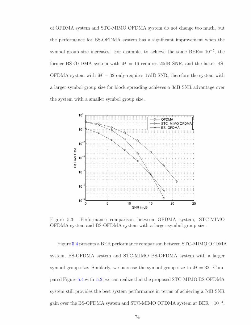
of OFDMA system and STC-MIMO OFDMA system do not change too much, but
the performance for BS-OFDMA system has a significant improvement when the
symbol group size increases. For example, to achieve the same BER= 10−5, the
former BS-OFDMA system with M = 16 requires 20dB SNR, and the latter BS-
OFDMA system with M = 32 only requires 17dB SNR, therefore the system with
a larger symbol group size for block spreading achieves a 3dB SNR advantage over
the system with a smaller symbol group size.
0 5 10 15 20 2510
−6
10−5
10−4
10−3
10−2
10−1
100
SNR in dB
Bit
Err
or R
ate
OFDMASTC−MIMO OFDMABS−OFDMA
Figure 5.3: Performance comparison between OFDMA system, STC-MIMOOFDMA system and BS-OFDMA system with a larger symbol group size.
Figure 5.4 presents a BER performance comparison between STC-MIMO OFDMA
system, BS-OFDMA system and STC-MIMO BS-OFDMA system with a larger
symbol group size. Similarly, we increase the symbol group size to M = 32. Com-
pared Figure 5.4 with 5.2, we can realize that the proposed STC-MIMO BS-OFDMA
system still provides the best system performance in terms of achieving a 7dB SNR
gain over the BS-OFDMA system and STC-MIMO OFDMA system at BER= 10−4,
74

respectively. Moreover, we also realize that the STC-MIMO BS-OFDMA system
with a larger symbol group size can achieve better performance than that with a
smaller symbol group size. The performance curve of the STC-MIMO BS-OFDMA
system with M = 32 gets closer to BER= 10−5 at 9dB SNR than the system with
M = 16 does.
0 2 4 6 8 10 12 14 16 1810
−6
10−5
10−4
10−3
10−2
10−1
100
SNR in dB
Bit
Err
or R
ate
STC−MIMO OFDMABS−OFDMASTC−MIMO BS−OFDMA
Figure 5.4: Performance comparison between STC-MIMO OFDMA system, BS-OFDMA system and STC-MIMO BS-OFDMA system with a larger symbol groupsize.
5.2.3 Simulation results for two receive antennas
As we described in the previous chapter, the application of multiple antennas at the
receiver can provide the proposed system with a higher order of diversity than the
single antenna does, therefore achieving a further performance improvement. Sim-
ulations are carried out to demonstrate this anticipated performance improvement.
In this case, we increase the receive antennas from one to two and maintain other
parameters. For computational simplicity, the symbol group size used this time is
75

back to M = 16.
Figure 5.5 presents a BER performance comparison between STC-MIMO BS-
OFDMA systems with one receive antenna and two receive antennas. As we can
see, the system with two receive antennas further improves system performance
by achieving nearly 3dB SNR gain over the system with one receive antenna at
BER= 10−5. Therefore, we may conclude that increasing receive antennas can offer
a higher diversity order and as a result, the system performance can be continuely
improved.
0 2 4 6 8 10 1210
−6
10−5
10−4
10−3
10−2
10−1
SNR in dB
Bit
Err
or R
ate
BSOFDMA−MIMO with 1RXBSOFDMA−MIMO with 2RX
Figure 5.5: Performance comparison between STC-MIMO BS-OFDMA systemswith one receive antenna and two receive antennas.
5.2.4 Simulation results for different linear equalizations
The system performance does not only depend on the proposed system encoding
schemes, which although are the most important factors, but also relies on the
different equalizations used for decoding process. As we described before, the ML
76

equalization increases computation complexity exponentially when the symbol group
size goes high, therefore it is not widely used in practice even though it is able to
theoretically provide the best system performance. In our project, we prefer using
linear equalizations, which include the MMSE equalization and the ZF equalization.
Of the two linear equalization techniques, MMSE equalization is more practical as
it considers the effect of noise in channels while the ZF equalization assumes no
noise is present. Consequently, the MMSE equalization is expected to result in
better system performance than the ZF equalization. This anticipated performance
improvement by MMSE equalization over ZF equalization is demonstrated by the
following simulation result.
Figure 5.6 presents a BER performance comparison between systems with dif-
ferent linear equalizations. In this case, we apply two linear equalizations, MMSE
and ZF equalizations, for BS-OFDMA system and STC-MIMO BS-OFDMA system,
respectively. This time, the symbol group size is M = 16 and one receive antenna
is used for the STC-MIMO BS-OFDMA system.
As we can see, for both systems the MMSE equalization achieves better BER per-
formance than the ZF equalization does. For example, for the BS-OFDMA system,
a 10dB SNR gain is achieved by the MMSE equalization over the ZF equalization at
BER of 10−3. For the STC-MIMO BS-OFDMA system, a 3dB SNR gain is achieved
by the MMSE equalization over the ZF equalization at BER of 10−4. Therefore,
regarding the performance of systems with linear equalizations, we can conclude
that the MMSE equalization is the best choice as it provides a compromise option
between performance and complexity. Note that we use the MMSE equalization for
all the previous simulation works.
77

0 5 10 15 20 2510
−6
10−5
10−4
10−3
10−2
10−1
100
SNR in dB
Bit
Err
or R
ate
STC−MIMO BS−OFDMA−ZFSTC−MIMO BS−OFDMA−MMSEBS−OFDMA−ZFBS−OFDMA−MMSE
Figure 5.6: Performance comparison between different linear equalizations.
5.3 Chapter summary
This chapter first presents the simulation implementation in detail in terms of in-
troducing useful parameters and some important implementation issues. The power
normalization is used to address the assumption that all systems in our simulations
have the same total transmit power. The antenna configurations are specified such
that the channels from each transmit antenna to each receive antenna are mutually
uncorrelated and their average power is normalized to unity. The other parameters
used in simulations are also given.
Numerical simulation results are subsequently provided. First, we present a BER
performance comparison between the conventional OFDMA system, BS-OFDMA
system, STC-MIMO OFDMA system and the proposed STC-MIMO BS-OFDMA
system. Among these considered systems, the proposed STC-MIMO BS-OFDMA
system provides the best performance due to diversity advantages from both block
78

spreading and STC-MIMO. Next, a BER performance comparison between those
systems with a larger symbol group size is presented. It is shown that the per-
formance improvement is achieved for BS-OFDMA and STC-MIMO BS-OFDMA
systems by increasing the symbol group size for block spreading. Then, a BER
performance comparison between the STC-MIMO BS-OFDMA system with one re-
ceive antenna and that system with two receive antennas. Compared to one receive
antenna, two receive antennas can provide a higher diversity order and therefore
improve the system performance. At last, a BER performance comparison between
systems with different linear equalizations is presented. For both BS-OFDMA sys-
tem and STC-MIMO OFDMA system, the MMSE equalization achieves better per-
formance than the ZF equalization does.
79

Chapter 6Conclusions
This thesis proposes a system design for the next generation wireless communica-
tions. The proposed system is called block spread OFDMA combined with STC-
MIMO (STC-MIMO BS-OFDMA) system. OFDM is a multicarrier modulation
technique of delivering high data rates with strong resistance to ISI. Considering
OFDMA as a strong candidate for multiple access technique of future wireless com-
munications, it is necessary to add it new features so that, besides being strong
to resist ISI, it can also combat the effect of frequency selective fading channels.
The block spreading technique is applied to provide OFDMA systems with addi-
tional frequency diversity. Due to our novel approach, the combination of block
spreading and OFDMA in the proposed system is simply addressed by using a com-
plex exponential sequence instead of any explicit precoding process and IFFT, thus
greatly reducing the system complexity. The STC-MIMO using Alamouti code is
further used to gain spatial diversity. The Alamouti code in our MIMO scheme is
imposed to block basis and performs in space and frequency. We design two receiver
architectures for different MIMO schemes; two transmit antennas and one receive
antenna MIMO scheme and two transmit antennas and two receive antennas MIMO
80

scheme. This chapter is organized as follows. In Section 6.1, we summarise the
major research activities undertaken during this project. In Section 6.2, we give the
concluding remarks.
6.1 Research summary
The research activities have been documented in several chapters of the thesis. They
are summarised as follows.
• Chapter 2: Overview of 4G
We briefly take a review of the evolution histroy of wireless communications
from 1G to 4G, with the emphasis on 4G system features. Multicarrier sys-
tems, such as OFDM and MC-CDMA, become the hottest technologies for 4G
systems. Some standardizations of 4G systems haven been developed based
on different perspectives.
• Chapter 3: Improvement for OFDM
We focus on the OFDM system and discuss several techniques to improve
system performance. Block spread approach is one of attractive techniques
to provide system with diversity gain and thus improve performance over fre-
quency selective channels. The common process to implement block spreading
on OFDM systems is to use spreading matrices before IFFT. This process
is known as precoding process. STC-MIMO is another technique to improve
OFDM system performance and can be effectively combined with OFDM sys-
tems. The idea of STC-MIMO is to take advantage of multipath channels and
offer spatial diversity.
81

• Chapter 4: Block spread OFDMA system with STC-MIMO
We propose an advanced OFDMA system where the block spreading tech-
nique and STC-MIMO scheme are effectively combined. In this system, block
spreading is effectively combined with OFDM modulation without any explicit
precoding process and IFFT, therefore reducing computation complexity. The
STC-MIMO using Alamouti code is imposed to block basis and performed in
space and frequency to gain additional diversity. The MIMO scheme is classi-
fied to MIMO with two transmit antennas and one receive antenna and MIMO
with two transmit antennas and two receive antennas.
• Chapter 5: System performance simulations
We conduct simulations to demonstrate the anticipated performance improve-
ment of the proposed system. We present a BER performance comparison
between OFDMA system, BS-OFDMA system, STC-MIMO OFDMA system
and the proposed STC-MIMO BS-OFDMA system. We also present a BER
performance comparison between the STC-MIMO BS-OFDMA systems with
different parameters, such as block size and number of receive antennas. Fi-
nally, we present a BER performance comparison between systems with MMSE
and ZF equalizations, respectively. Simulation results are consequently pro-
vided.
6.2 Conclusion
In conclusion, this thesis has proposed a STC-MIMO BS-OFDMA system for next
generation wireless communications. The system has simpler structures to effectively
combine block spread, STC-MIMO and OFDMA, therefore greatly reducing compu-
82

tational complexity. Our simulations indicate that the proposed system can result in
significant improvement in the BER performance compared to other systems. Using
larger block size for spreading and more receive antennas can both further improve
system performance due to higher order of diversity advantage they may offer. In
terms of accuracy and computational complexity, the MMSE equalization is more
suitable for the proposed system on practical applications.
83

References
[1] H. Sampath, S. Talwar, J. Tellado, V. Erceg, and A. Paulraj, “A fourth-
generation MIMO-OFDM broadband wireless system: design, performance,
and field trial results,” IEEE Communications Magazine, vol. 40, no. 9, pp.
143–149, 2002.
[2] H. Yang, “A road to future broadband wireless access: MIMO-OFDM-based
air interface,” IEEE Communications Magazine, vol. 43, no. 1, pp. 53–60, 2005.
[3] K. R. Santhi, V. K. Srivastava, G. SenthilKumaran, and A. Butare, “Goals
of true broad band’s wireless next wave (4G-5G),” in IEEE 58th Vehicular
Technology Conference, vol. 4, 2003, pp. 2317–2321.
[4] B. G. Evans and K. Baughan, “Visions of 4G,” Electronics and Communication
Engineering Journal, vol. 12, no. 6, pp. 293–303, 2000.
[5] H. Jeounglak, S. Kim, and D. Kim, “A phased approach to 4G mobile network
system,” in 10th International Conference on Telecommunications, S. H. Kim,
Ed., vol. 2, 2003, pp. 1318–1322.
[6] J. Sun, J. Sauvola, and D. Howie, “Features in future: 4G visions from a
84

technical perspective,” in IEEE Global Telecommunications Conference, vol. 6,
2001, pp. 3533–3537.
[7] R. Caldwell and A. Anpalagan, “Meeting mobile’s demands with multicarrier
systems,” IEEE Potentials, vol. 24, no. 5, pp. 27–31, 2005.
[8] F. Adachi, “Evolution towards broadband wireless systems,” in The 5th Inter-
national Symposium on Wireless Personal Multimedia Communications, vol. 1,
2002, pp. 19–26.
[9] K. Murota and N. DoCoMo, “Mobile communications trends in japan and NTT
DoCoMo’s activities towards 21st century,” in ACTS Mobile Summit99, Sor-
rento, Italy, 1999.
[10] J. Silva, “Beyond IMT-2000,” in ITU-R WP8F workshop, Geneva, 2000.
[11] F. Williams, “Fourth generation mobile,” in ACTS Mobile Summit99, Sorrento,
Italy, 1999.
[12] H. Huomo, “Fourth generation mobile,” in ACTS Mobile Summit99, Sorrento,
Italy, 1999.
[13] S. Frattasi, R. L. Olsen, M. De Sanctis, F. H. P. Fitzek, and R. Prasad, “Het-
erogeneous services and architectures for next-generation wireless networks,” in
2nd International Symposium on Wireless Communication Systems, 2005, pp.
213–217.
[14] Y. Ji and P. Zhang, “Muse: a vision for 4G service and architecture,” in IEEE
60th Vehicular Technology Conference, vol. 7, 2004, pp. 4842–4845.
85

[15] “Everywhere and at any time: Wireless multimedia communications,” in VDE-
IGT Positionspapier Mobil-kiommunication, 2005.
[16] J. M. Pereira, “Fourth generation: now, it is personal!” in The 11th IEEE
International Symposium on Personal, Indoor and Mobile Radio Communica-
tions, vol. 2, 2000, pp. 1009–1016.
[17] S. J. Vaughan-Nichols, “OFDM: back to the wireless future,” Computer, vol. 35,
no. 12, pp. 19–21, 2002.
[18] S. G. Glisic, Advanced wireless communications : 4G cognitive and cooperative
broadband technology, 2nd ed. Chichester :: John Wiley, 2007.
[19] K. Baybakov, T. Sviridova, M. Lobur, and R. Kohut, “Using OFDM for multi-
ple access schemes in 4G communication systems,” in The Experience of Design-
ing and Application of CAD Systems in Microelectronics, 2003, pp. 572–573.
[20] C. Liu and F. Li, “On spectrum modeling of OFDM signals for digital broad-
casting,” in 7th International Conference on Signal Processing, vol. 3, 2004, pp.
1886–1889.
[21] K. Zheng, L. Huang, W. Wang, and G. Yang, “TD-CDM-OFDM: Evolution of
TD-SCDMA toward 4G,” IEEE Communications Magazine, vol. 43, no. 1, pp.
45–52, 2005.
[22] H. Schulze and C. Luders, Theory and applications of OFDM and CDMA :
wideband wireless communications. Chichester :: Wiley, 2005.
[23] G. Parsaee and A. Yarali, “OFDMA for the 4th generation cellular networks,” in
Electrical and Computer Engineering Conference, vol. 4, 2004, pp. 2325–2330.
86
[24] L. Loyola and T. Miki, “An OFDMA/CDMA-based bandwidth resource allo-
cation scheme for future broadband mobile networks,” in IEEE 56th Vehicular
Technology Conference, vol. 1, 2002, pp. 42–46.
[25] R. Esmailzadeh, M. Nakagawa, and A. Jones, “TDD-CDMA for the 4th gen-
eration of wireless communications,” IEEE Wireless Communications, vol. 10,
no. 4, pp. 8–15, 2003.
[26] K. Kim, “Key technologies for the next generation wireless communications,”
in Hardware/software codesign and system synthesis, 2006, pp. 266–269.
[27] J. G. Andrews, A. Ghosh, and R. Muhamed, Fundamentals of WiMAX : un-
derstanding broadband wireless networking. Upper Saddle River, N.J. ; London
:: Prentice Hall, 2007.
[28] S. V. Anand, “Next GEN mobile terminal architecture: A vision,” in Proceed-
ings of the First Mobile Computing and Wireless Communication International
Conference, 2006, pp. 133–138.
[29] U. H. Reimers, “DVB-the family of international standards for digital video
broadcasting,” Proceedings of the IEEE, vol. 94, no. 1, pp. 173–182, 2006.
[30] U. Ladebusch and C. A. Liss, “Terrestrial DVB (DVB-T): a broadcast technol-
ogy for stationary portable and mobile use,” Proceedings of the IEEE, vol. 94,
no. 1, pp. 183–193, 2006.
[31] V. Ollikainen and C. Peng, “A handover approach to DVB-H services,” in IEEE
International Conference on Multimedia and Expo, 2006, pp. 629–632.
87
[32] K. Ohsaki, T. Kimura, and N. Kawai, “Transmission structure of digital broad-
casting,” in IEEE International Conference on Communications, 1994, pp. 853–
858.
[33] H. Asami and M. Sasaki, “Outline of ISDB systems,” Proceedings of the IEEE,
vol. 94, no. 1, pp. 248–250, 2006.
[34] M. Takada and M. Saito, “Transmission system for ISDB-T,” Proceedings of
the IEEE, vol. 94, no. 1, pp. 251–256, 2006.
[35] H. Katoh, “Transmission system for ISDB-S,” Proceedings of the IEEE, vol. 94,
no. 1, pp. 289–295, 2006.
[36] B. Umasankar and X. Fernando, “OFDM impairment mitigation techniques,”
in Second International Conference on Access Networks and Workshops, 2007,
pp. 1–6.
[37] S. Kim, J. Chung, and H. Ryu, “PAPR reduction of the OFDM signal by the
SLM-based WHT and DSI method,” in IEEE Region 10 Conference, 2006, pp.
1–4.
[38] Y. Park and S. L. Miller, “Peak-to-average power ratio suppression schemes in
DFT based OFDM,” in IEEE Vehicular Technology Conference, vol. 1, 2000,
pp. 292–297.
[39] H. Wang, “PAPR reduction for OFDM system with a class of HNN,” in Inter-
national Symposium on Communications and Information Technologies, 2006,
pp. 492–497.
88

[40] D. Wulich, “Definition of efficient PAPR in OFDM,” IEEE Communications
Letters, vol. 9, no. 9, pp. 832–834, 2005.
[41] C. R. N. Athaudage, “BER sensitivity of OFDM systems to time synchroniza-
tion error,” in The 8th International Conference on Communication Systems,
vol. 1, 2002, pp. 42–46.
[42] C. Yan, J. Fang, Y. Tang, S. Li, and Y. Li, “OFDM synchronization using PN
sequence and performance,” in 14th IEEE Proceedings on Personal, Indoor and
Mobile Radio Communications, vol. 1, 2003, pp. 936–939.
[43] S. K. Manusani, R. S. Kshetrimayum, and R. Bhattacharjee, “Robust time and
frequency synchronization in OFDM based 802.11a WLAN systems,” in Annual
India Conference, 2006, pp. 1–4.
[44] T. C. W. Schenk and A. van Zelst, “Frequency synchronization for MIMO
OFDM wireless LAN systems,” in IEEE 58th Vehicular Technology Conference,
vol. 2, 2003, pp. 781–785.
[45] C. Athaudage, J. Wang, and A. Jayalath, “An efficient framework to exploit
frequency diversity in OFDM: Precoding with adaptive subcarrier selection,”
in IEEE 17th International Symposium on Personal, Indoor and Mobile Radio
Communications, 2006, pp. 1–5.
[46] L. Van der Perre, J. Tubbax, F. Horlin, and H. A. De Man, “A single-
carrier/OFDM comparison for broadband wireless communication,” in IEEE
International Conference on Acoustics, Speech, and Signal Processing, vol. 2,
2004, pp. ii–329–32.
89

[47] Q. Li, K. Li, and K. Teh, “MIMO-OFDM systems based on space-time coding
and OFDM carrier block spreading,” in The 6th International Conference on
Information, Communications and Signal Processing, 2007, pp. 1–5.
[48] T. Seki, M. Itami, H. Ohta, and K. Itoh, “A study of OFDM system applying
frequency diversity,” in The 11th IEEE International Symposium on Personal,
Indoor and Mobile Radio Communications, vol. 2, 2000, pp. 1385–1389.
[49] R. Geevarghese and R. K. Rao, “Adaptive frequency diversity using OFDM for
wireless communications,” in Canadian Conference on Electrical and Computer
Engineering, vol. 2, 2003, pp. 809–812.
[50] K. Eunseok and D. Hong, “Improved space-time block coding with frequency
diversity for OFDM systems,” in IEEE International Conference on Commu-
nications, vol. 6, 2004, pp. 3217–3220.
[51] A. D. S. Jayalath and C. Tellambura, “The use of interleaving to reduce the
peak-to-average power ratio of an OFDM signal,” in IEEE Global Telecommu-
nications Conference, vol. 1, 2000, pp. 82–86.
[52] M. Lin, Y. Tsai, and C. Yang, “Selective-mapping type peak power reduction
techniques for turbo coded OFDM,” in International Conference on Wireless
Networks, Communications and Mobile Computing, T. Yung-Chih, Ed., vol. 1,
2005, pp. 119–122.
[53] H. Ryu, J. Kim, and H. Ryu, “Interleaving method without side information
for the PAPR reduction of OFDM system,” in International Symposium on
Communications and Information Technologies, 2007, pp. 72–76.
90

[54] F. Zbynek, M. Roman, and S. Vladimir, “Interleaving optimization in OFDM
PAPR reduction,” in 17th International Conference Radioelektronika, 2007, pp.
1–3.
[55] M. L. McCloud, “Coded block OFDM for the frequency selective fading chan-
nel,” in Conference Record of the Thirty-Eighth Asilomar Conference on Sig-
nals, Systems and Computers, vol. 1, 2004, pp. 329–333.
[56] ——, “Optimal binary spreading for block OFDM on multipath fading chan-
nels,” in IEEE Wireless Communications and Networking Conference, vol. 2,
2004, pp. 965–970.
[57] A. Bury, J. Egle, and J. Lindner, “Diversity comparison of spreading trans-
forms for multicarrier spread spectrum transmission,” IEEE Transactions on
Communications, vol. 51, no. 5, pp. 774–781, 2003.
[58] M. L. McCloud, “Analysis and design of short block OFDM spreading matrices
for use on multipath fading channels,” IEEE Transactions on Communications,
vol. 53, no. 4, pp. 656–665, 2005.
[59] I. Raad and X. Huang, “A new approach to BSOFDM - parallel concatenated
spreading matrices OFDM,” in International Symposium on Communications
and Information Technologies, 2007, pp. 77–81.
[60] I. S. Raad, X. Huang, and R. Raad, “A new spreading matrix for block spread
OFDM,” in IEEE Singapore International Conference on Communication sys-
tems, 2006, 2006, pp. 1–5.
91

[61] L. Tran, X. Huang, E. Dutkiewicz, and J. A. Chicharo, “STC-MIMO block
spread OFDM in frequency selective rayleigh fading channels,” in IEEE Sym-
posium on Computers and Communications, 2006, pp. 277–282.
[62] I. Raad, X. Huang, and R. Raad, “New higher order rotation spreading matrix
for BSOFDM,” in The 2nd International Conference on Wireless Broadband
and Ultra Wideband Communications, 2007, pp. 17–17.
[63] I. Raad, X. Huang, and D. Lowe, “A study of different angles for the new spread
matrix for BSOFDM in UWB channels,” in Third International Conference on
Wireless and Mobile Communications, 2007, pp. 67–67.
[64] I. Raad, X. Huang, and R. Raad, “A study of different angles for higher or-
der rotation spreading matrix for BSOFDM in UWB channels,” in The 2nd
International Conference on Wireless Broadband and Ultra Wideband Commu-
nications, 2007, pp. 18–18.
[65] D. Gesbert, M. Shafi, D. Shiu, P. J. Smith, and A. Naguib, “From theory
to practice: an overview of MIMO space-time coded wireless systems,” IEEE
Journal on Selected Areas in Communications, vol. 21, no. 3, pp. 281–302, 2003.
[66] S. M. Alamouti, “A simple transmit diversity technique for wireless communi-
cations,” IEEE Journal on Selected Areas in Communications, vol. 16, no. 8,
pp. 1451–1458, 1998.
[67] A. Zooghby, Smart antenna engineering. Boston: Artech House, 2005.
[68] A. Wittneben, “Basestation modulation diversity for digital simulcast,” in 41st
IEEE Vehicular Technology Conference, 1991, pp. 848–853.
92

[69] ——, “A new bandwidth efficient transmit antenna modulation diversity
scheme for linear digital modulation,” in IEEE International Conference on
Communications, vol. 3, 1993, pp. 1630–1634.
[70] N. Seshadri and J. H. Winters, “Two signaling schemes for improving the error
performance of frequency-division-duplex (FDD) transmission systems using
transmitter antenna diversity,” in IEEE 43rd Vehicular Technology Conference,
1993, pp. 508–511.
[71] J. H. Winters, “The diversity gain of transmit diversity in wireless systems with
rayleigh fading,” IEEE Transactions on Vehicular Technology, vol. 47, no. 1,
pp. 119–123, 1998.
[72] B. Vucetic, Space-time coding. Hoboken, NJ: Wiley, 2003.
[73] D. Agrawal, V. Tarokh, A. Naguib, and N. Seshadri, “Space-time coded OFDM
for high data-rate wireless communication over wideband channels,” in 48th
IEEE Vehicular Technology Conference, vol. 3, 1998, pp. 2232–2236.
[74] V. Tarokh, N. Seshadri, and A. R. Calderbank, “Space-time codes for high data
rate wireless communication: performance criterion and code construction,”
IEEE Transactions on Information Theory, vol. 44, no. 2, pp. 744–765, 1998.
[75] B. Lu and X. Wang, “Space-time code design in OFDM systems,” in IEEE
Global Telecommunications Conference, vol. 2, 2000, pp. 1000–1004.
[76] V. Tarokh, H. Jafarkhani, and A. R. Calderbank, “Space-time block codes from
orthogonal designs,” IEEE Transactions on Information Theory, vol. 45, no. 5,
pp. 1456–1467, 1999.
93

[77] ——, “Space-time block coding for wireless communications: performance re-
sults,” IEEE Journal on Selected Areas in Communications, vol. 17, no. 3, pp.
451–460, 1999.
[78] R. S. Blum, L. Ye Geoffrey, J. H. Winters, and C. Yan, “Improved space-
time coding for MIMO-OFDM wireless communications,” IEEE Transactions
on Communications, vol. 49, no. 11, pp. 1873–1878, 2001.
[79] R. S. Blum, Q. Yan, Y. Li, and J. H. Winters, “Improved techniques for 4
transmit and 4 receive antenna MIMO-OFDM for wireless communications,”
in IEEE VTS 53rd Vehicular Technology Conference, vol. 2, 2001, pp. 1298–
1302.
[80] S. Suthaharan, A. Nallanathan, and B. Kannan, “Space-time coded MIMO-
OFDM for high capacity and high data-rate wireless communication over fre-
quency selective fading channels,” in 4th International Workshop on Mobile and
Wireless Communications Network, 2002, pp. 424–428.
[82] R. Harish and T. M. Duman, “Space-time coded ofdm with low papr,” in IEEE
Global Telecommunications Conference, vol. 2, 2003, pp. 799–803.
[83] Z. Liu, Y. Xin, and G. B. Giannakis, “Space-time-frequency coded OFDM over
frequency-selective fading channels,” IEEE Transactions on Signal Processing,
vol. 50, no. 10, pp. 2465–2476, 2002.
[84] S. Savary, H. T. Huynh, J. Y. Chouinard, and S. Roy, “A space-frequency-
time diversity scheme for MIMO-OFDM systems,” in Canadian Conference on
Electrical and Computer Engineering, 2005, pp. 1375–1379.
94

[81] J. Kim, J. Heath, R. W., and E. J. Powers, “Receiver designs for Alamouti
coded OFDM systems in fast fading channels,” IEEE Transactions on Wireless
Communications, vol. 4, no. 2, pp. 550–559, 2005.
[85] J. Yue and J. D. Gibson, “Performance of a space-time block coded OFDM sys-
tem,” in Conference Record of the Thirty-Sixth Asilomar Conference on Signals,
Systems and Computers, vol. 2, 2002, pp. 1862–1866.
[86] M. Uysal, N. Al-Dhahir, and C. N. Georghiades, “A space-time block-coded
OFDM scheme for unknown frequency-selective fading channels,” in IEEE In-
ternational Symposium on Personal, Indoor and Mobile Radio Communica-
tions, ., Ed., vol. 2, 2001, pp. G–93–G–97.
[87] B. Chiang, D. Lin, H. Li, and J. Wang, “Improved transmit diversity block
coded OFDM systems for highly dispersive channels,” in The 57th IEEE Semi-
annual Vehicular Technology Conference, vol. 2, 2003, pp. 1173–1177.
95