MIMIH II Man Metric 0611 - Northern Plumbing
44
MI/MIH ™ Boilers Series Gas Installation, Operation & Maintenance Manual
Transcript of MIMIH II Man Metric 0611 - Northern Plumbing
MI/MIH™
Boilers
SeriesGas
Installation,Operation &MaintenanceManual

USING THIS MANUAL 1A. INSTALLATION SEQUENCE . . . . . . . . . . . . .1B. SPECIAL ATTENTION BOXES . . . . . . . . . . . .1
1. PREINSTALLATION 2
A. ACCESSIBILITY CLEARANCES . . . . . . . . . . .2B. CLEARANCE FROM COMBUSTIBLE
CONSTRUCTION . . . . . . . . . . . . . . . . . . . . . .2C. AIR FOR COMBUSTION AND
VENTILATION . . . . . . . . . . . . . . . . . . . . . . . . .2
D. INSTALLATION SURVEY . . . . . . . . . . . . . . . .5
E. PLANNING THE LAYOUT . . . . . . . . . . . . . . . .5
2. BOILER SET-UP 6
3. WATER PIPING AND CONTROLS 7A. BOILER SUPPLY AND RETURN . . . . . . . . . . .7B. SAFETY RELIEF VALVE . . . . . . . . . . . . . . . . .8C. PIPING FOR ZONED SYSTEMS . . . . . . . . . .9D. EXPANSION TANK . . . . . . . . . . . . . . . . . . . .10E. INDIRECT-FIRED WATER HEATER . . . . . . .10F. FREEZE PROTECTION . . . . . . . . . . . . . . . . .10
4. VENTING 11A. INTEGRAL DRAFT HOOD . . . . . . . . . . . . . .11B. VENT DAMPER INSTALLATION –
GENERAL . . . . . . . . . . . . . . . . . . . . . . . . . . .11C. VENT PIPING AND CHIMNEY . . . . . . . . . . .12D. BOILER REMOVAL FROM COMMON
VENTING SYSTEM . . . . . . . . . . . . . . . . . . .13
5. GAS PIPING 14
6. ELECTRICAL 16A. WIRING . . . . . . . . . . . . . . . . . . . . . . . . . . . . .16B. ZONED SYSTEM WIRING . . . . . . . . . . . . . .16C. CONTROLS . . . . . . . . . . . . . . . . . . . . . . . . . .16D. SEQUENCE OF OPERATION . . . . . . . . . . . .17
7. START-UP PROCEDURES 21A. COMPLETING THE INSTALLATION . . . . . .21B. CONTROL DESCRIPTIONS . . . . . . . . . . . . .25C. ADJUSTMENT OF GAS PRESSURE
REGULATOR . . . . . . . . . . . . . . . . . . . . . . . . .25D. ADJUSTMENT OF PILOT GAS FLOW . . . . .25E. CHECKING BURNER INPUT . . . . . . . . . . . . .26F. CHECK-OUT PROCEDURE . . . . . . . . . . . . . .26
8. TROUBLESHOOTING 28A. SHUT-DOWN CAUSED BY PILOT OUTAGE,
BLOCKED VENT SHUT-OFF SWITCH ORFLAME ROLL-OUT SAFETY SHUT-OFFSWITCH . . . . . . . . . . . . . . . . . . . . . . . . . . . .28
B. TROUBLESHOOTING GUIDES . . . . . . . . . .28
9. MAINTENANCE 31A. GENERAL . . . . . . . . . . . . . . . . . . . . . . . . . . .32B. DAILY (WITH BOILER IN USE) . . . . . . . . . . .32C. WEEKLY (WITH BOILER IN USE) . . . . . . . . .32D. MONTHLY (WITH BOILER IN USE) . . . . . . .32E. ANNUALLY (BEFORE START OF HEATING
SEASON) . . . . . . . . . . . . . . . . . . . . . . . . . . .33
10. BOILER DIMENSIONS & RATINGS 34
11. REPAIR PARTS 35A. BASE/COMBUSTIBLE FLOOR PAN . . . . . . .35B. MANIFOLD, GAS VALVE & PILOT . . . . . . . .36C. BLOCK/DRAFT HOOD & JACKET . . . . . . . .38D. CONTROLS/CIRCULATOR/VENT
DAMPER & CONVERSION KITS . . . . . . . . .40
TABLE OF CONTENTS
TABLE OF CONTENTS

1
A. INSTALLATION SEQUENCEFollow the installation instructions provided in thismanual in the order shown. The order of theseinstructions has been set in order to provide the installerwith a logical sequence of steps that will minimizepotential interferences and maximize safety duringboiler installation.
B. SPECIAL ATTENTION BOXESThroughout this manual you will see special attentionboxes intended to supplement the instructions and makespecial notice of potential hazards. These categoriesmean, in the judgment of PB Heat, LLC.:
Indicates special attention is needed, but not directlyrelated to potential personal injury or propertydamage.
NOTICE
Indicates a condition or hazard which will or cancause minor personal injury or property damage.
CAUTION
DANGERIndicates a condition or hazard which will causesevere personal injury, death or major propertydamage.
USING THIS MANUAL
USING THIS MANUAL
Indicates a condition or hazard which may causesevere personal injury, death or major propertydamage.
WARNING
2
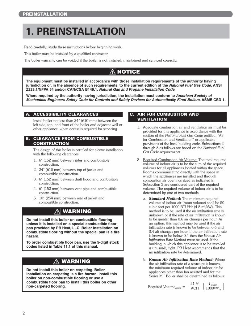
A. ACCESSIBILITY CLEARANCESInstall boiler not less than 24″ (610 mm) between theleft side, top, and front of the boiler and adjacent wall orother appliance, when access is required for servicing.
B. CLEARANCE FROM COMBUSTIBLE CONSTRUCTIONThe design of this boiler is certified for alcove installationwith the following clearances:
1. 6″ (152 mm) between sides and combustibleconstruction.
2. 24″ (610 mm) between top of jacket andcombustible construction.
3. 6″ (152 mm) between draft hood and combustibleconstruction.
4. 6″ (152 mm) between vent pipe and combustibleconstruction.
5. 10″ (254 mm) between rear of jacket andcombustible construction.
C. AIR FOR COMBUSTION ANDVENTILATION
1. Adequate combustion air and ventilation air must beprovided for this appliance in accordance with thesection of the National Fuel Gas Code entitled, “Airfor Combustion and Ventilation” or applicableprovisions of the local building code. Subsections 2through 8 as follows are based on the National FuelGas Code requirements.
2. Required Combustion Air Volume: The total requiredvolume of indoor air is to be the sum of the requiredvolumes for all appliances located within the space.Rooms communicating directly with the space inwhich the appliances are installed and throughcombustion air openings sized as indicated inSubsection 3 are considered part of the requiredvolume. The required volume of indoor air is to bedetermined by one of two methods.
a. Standard Method: The minimum requiredvolume of indoor air (room volume) shall be 50cubic feet per 1000 BTU/Hr (4.8 m3/kW). Thismethod is to be used if the air infiltration rate isunknown or if the rate of air infiltration is knownto be greater than 0.6 air changes per hour. Asan option, this method may be used if the airinfiltration rate is known to be between 0.6 and0.4 air changes per hour. If the air infiltration rateis known to be below 0.4 then the Known AirInfiltration Rate Method must be used. If thebuilding in which this appliance is to be installedis unusually tight, PB Heat recommends that theair infiltration rate be determined.
b. Known Air Infiltration Rate Method: Wherethe air infiltration rate of a structure is known,the minimum required volume of indoor air forappliances other than fan assisted and for theSeries MI™ Boiler shall be determined as follows:
PREINSTALLATION
1. PREINSTALLATIONRead carefully, study these instructions before beginning work.
This boiler must be installed by a qualified contractor.
The boiler warranty can be voided if the boiler is not installed, maintained and serviced correctly.
The equipment must be installed in accordance with those installation requirements of the authority having jurisdiction or, in the absence of such requirements, to the current edition of the National Fuel Gas Code, ANSIZ223.1/NFPA 54 and/or CAN/CSA B149.1, Natural Gas and Propane Installation Code.
Where required by the authority having jurisdiction, the installation must conform to American Society ofMechanical Engineers Safety Code for Controls and Safety Devices for Automatically Fired Boilers, ASME CSD-1.
NOTICE
Do not install this boiler on carpeting. Boilerinstallation on carpeting is a fire hazard. Install thisboiler on non-combustible flooring or use acombustible floor pan to install this boiler on othernon-carpeted flooring.
WARNING
Do not install this boiler on combustible flooringunless it is installed on a special combustible floorpan provided by PB Heat, LLC. Boiler installation oncombustible flooring without the special pan is a firehazard.
To order combustible floor pan, use the 5-digit stockcodes listed in Table 11.1 of this manual.
WARNING
21 ft3 I otherACH 1000Btu/hr
Required Volumeother =⎛⎜⎝ ⎛
⎜⎝

3
where:Iother = Input of appliances other than fan
assisted in Btu/hrACH = air change per hour (percent of the
volume of the space exchanged perhour, expressed as a decimal)
For fan assisted appliances, calculate the requiredvolume of air using the following equation:
Ifan = Input of the fan assisted appliances inBtu/hr
Note: These calculations are not to be used forinfiltration rates greater than 0.60 ACH.
3. Indoor Air Opening Size and Location: Openingsconnecting indoor spaces shall be sized and locatedas follows:a. Combining spaces on the same floor:
Provide two permanent openings communicatingwith additional spaces that have a minimum freearea of 1 in2 per 1000 Btu/hr (22 cm2 per 1000 W)of the total input rating of all gas fired equipmentbut not less than 100 in2 (645 cm2). Oneopening is to begin within 12 inches (305 mm)from the top of the space and the other is tobegin within 12 inches (305 mm) from the floor.The minimum dimension of either of theseopenings shall be 3 inches (76 mm). See Figure1.1 for an illustration of this arrangement.
b. Combining spaces on different floors:Provide one or more permanent openingscommunicating with additional spaces that havea total minimum free area of 2 in2 per 1000Btu/hr (44 cm2 per 1000 W) of total input ratingof all equipment. See Figure 1.2 for anillustration of this arrangement.
4. Outdoor Combustion Air: Outdoor combustion air isto be provided through one or two permanentopenings. The minimum dimension of these airopenings is 3 inches (76 mm).a. Two Permanent Opening Method: Provide
two permanent openings. One opening is tobegin within 12 inches (305 mm) of the top ofthe space and the other is to begin within 12inches (305 mm) of the floor. The openings areto communicate directly or by ducts with theoutdoors or with spaces that freely communicatewith the outdoors. The size of the openings shallbe determined as follows:
i. Where communicating directly or throughvertical ducts with the outdoors each openingshall have a minimum free area of 1 in2 per4000 Btu/hr (22 cm2 per 4000 W) of totalinput rating for all equipment in the space.See Figure 1.3 for openings directlycommunicating with the outdoors or Figure1.4 for openings connected by ducts to theoutdoors.
PREINSTALLATION
15 ft3 I fan
ACH 1000Btu/hrRequired Volumefan =
⎛⎜⎝ ⎛
⎜⎝
Figure 1.1: Air Openings – All Air from Indoorson the Same Floor
Figure 1.2: Air Openings – All Air from Indoorson Different Floors
Figure 1.3: Air Openings – All Air Directly fromOutdoors

4
ii. Where communicating with the outdoorsthrough horizontal ducts, each opening shallhave a minimum free area of 1 in2 per 2000Btu/hr (22 cm2 per 2000 W) of total ratedinput for all appliances in the space. SeeFigure 1.5.
b. One Permanent Opening Method: Provideone permanent opening beginning within 12inches (305 mm) of the top of the space. Theopening shall communicate directly with theoutdoors, communicate through a vertical orhorizontal duct, or communicate with a spacethat freely communicates with the outdoors. Theopening shall have a minimum free area of 1 in2
per 3000 Btu/hr of total rated input for allappliances in the space and not less than thesum of the cross-sectional areas of all ventconnectors in the space. The gas-fired equipmentshall have clearances of at least 1 inch (25 mm)from the sides and back and 6 inches (150 mm)from the front of the appliance. See Figure 1.6for this arrangement.
5. Combination Indoor and Outdoor Combustion Air:If the required volume of indoor air exceeds theavailable indoor air volume, outdoor air openings orducts may be used to supplement the availableindoor air provided:a. The size and location of the indoor openings
comply with Subsection 3.
b. The outdoor openings are to be located inaccordance with Subsection 4.
c. The size of the outdoor openings are to be sizedas follows:
where:Areq = minimum area of outdoor openings.Afull = full size of outdoor openings calculated
in accordance with Subsection 4.Vavail = available indoor air volumeVreq = required indoor air volume
6. Engineered Installations: Engineered combustion airinstallations shall provide an adequate supply ofcombustion, ventilation, and dilution air and shall beapproved by the authority having jurisdiction.
7. Mechanical Combustion Air Supply:
a. In installations where all combustion air isprovided by a mechanical air supply system, thecombustion air shall be supplied from theoutdoors at the minimum rate of 0.35 ft3/min per1000 Btu/hr (0.034 m3/min per 1000 W) of thetotal rated input of all appliances in the space.
b. In installations where exhaust fans are installed,additional air shall be provided to replace theexhaust air.
PREINSTALLATION
Figure 1.4: Air Openings – All Air from Outdoorsthrough Vertical Ducts
Figure 1.5: Air Openings – All Air from Outdoorsthrough Horizontal Ducts
Figure 1.6: Air Openings – All Air from Outdoorsthrough One Opening
Vavail1 –Vreq
Areq = Afull x⎛⎜⎝ ⎛
⎜⎝
5
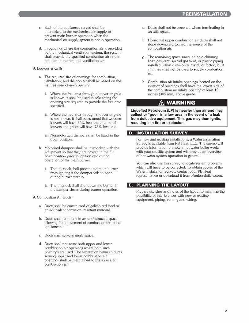
c. Each of the appliances served shall beinterlocked to the mechanical air supply toprevent main burner operation when themechanical air supply system is not in operation.
d. In buildings where the combustion air is providedby the mechanical ventilation system, the systemshall provide the specified combustion air rate inaddition to the required ventilation air.
8. Louvers & Grills:
a. The required size of openings for combustion,ventilation, and dilution air shall be based on thenet free area of each opening.
i. Where the free area through a louver or grilleis known, it shall be used in calculating theopening size required to provide the free areaspecified.
ii. Where the free area through a louver or grilleis not known, it shall be assumed that woodenlouvers will have 25% free area and metallouvers and grilles will have 75% free area.
iii. Nonmotorized dampers shall be fixed in theopen position.
b. Motorized dampers shall be interlocked with theequipment so that they are proven in the fullopen position prior to ignition and duringoperation of the main burner.
i. The interlock shall prevent the main burnerfrom igniting if the damper fails to openduring burner startup.
ii. The interlock shall shut down the burner ifthe damper closes during burner operation.
9. Combustion Air Ducts
a. Ducts shall be constructed of galvanized steel oran equivalent corrosion- resistant material.
b. Ducts shall terminate in an unobstructed space,allowing free movement of combustion air to theappliances.
c. Ducts shall serve a single space.
d. Ducts shall not serve both upper and lowercombustion air openings where both suchopenings are used. The separation between ductsserving upper and lower combustion airopenings shall be maintained to the source ofcombustion air.
e. Ducts shall not be screened where terminating inan attic space.
f. Horizontal upper combustion air ducts shall notslope downward toward the source of thecombustion air.
g. The remaining space surrounding a chimneyliner, gas vent, special gas vent, or plastic pipinginstalled within a masonry, metal, or factory builtchimney shall not be used to supply combustionair.
h. Combustion air intake openings located on theexterior of buildings shall have the lowest side ofthe combustion air intake opening at least 12inches (305 mm) above grade.
D. INSTALLATION SURVEYFor new and existing installations, a Water InstallationSurvey is available from PB Heat, LLC. The survey willprovide information on how a hot water boiler workswith your specific system and will provide an overviewof hot water system operation in general.
You can also use this survey to locate system problemswhich will have to be corrected. To obtain copies of theWater Installation Survey, contact your PB Heatrepresentative or download it from PeerlessBoilers.com.
E. PLANNING THE LAYOUTPrepare sketches and notes of the layout to minimize thepossibility of interferences with new or existingequipment, piping, venting and wiring.
Liquefied Petroleum (LP) is heavier than air and maycollect or “pool” in a low area in the event of a leakfrom defective equipment. This gas may then ignite,resulting in a fire or explosion.
WARNING
PREINSTALLATION

6
BOILER SET-UP
1. Provide a sound, level foundation. Locate boiler asnear to the chimney or outside wall as possible andcentralized with respect to the heating system.
2. Locate boiler in front of installation position before removing crate.
3. If using combustible floor pan, position pan onfoundation or flooring.
4. Separate the wood shipping pallet from the boilerbase by removing two (2) hold-down bolts at eachend of the boiler base.
5. Move boiler into final position. If using combustiblefloor pan, install boiler on pan as outlined in theinstructions included with the pan.
2. BOILER SET-UP

7
A. BOILER SUPPLY AND RETURN
1. Size the supply and return to suit the system. Atypical piping arrangement is shown in Figure 3.1.Refer also to the I=B=R Guide - ResidentialHydronic Heating Installation/Design and the PBHeat Water Survey for additional guidance duringwater piping installation.
2. Return Piping:Pipe the drain valve to a tee, provided, and the 1-1/4 NPT return tapping near the bottom of the leftsection. Pipe the return to the tee. Pipe the drainvalve nipples and tee to the 1-1/4 NPT returntapping as shown in Figure 3.1.
3. Supply Piping:Pipe the supply to the 1-1/2 NPT supply tapping atthe top and rear of the boiler.
4. When system return water temperature will be below130°F (54°C), pipe the boiler with a bypassarrangement to blend the system return and hotsupply to obtain at least 130°F (54°C) entering theboiler. For more information on bypass piping,consult the PB Heat Water Survey.
3. WATER PIPING AND CONTROLS
Figure 3.1: Supply and Return Piping
WATER PIPING AND CONTROLS

8
6. Install this boiler so that the gas ignition systemcomponents are protected from water (dripping,spraying, etc.) during appliance operation andservice (circulator replacement, condensate trap,control replacements, etc.).
7. If this boiler and distribution system is used inconjunction with a refrigeration system, pipe thechilled medium in parallel with the boiler and installthe proper valve to prevent the chilled medium fromentering the boiler. A drawing illustrating this hook-up is provided in Figure 3.2.
8. When the boiler is connected to heating coils located in air handling units where they may beexposed to refrigerated air circulation, install flowcontrol valves or other automatic means to preventgravity circulation of the boiler water during thecooling cycle.
9. If this boiler is installed above radiation level,provide a low water cutoff device, either as a part ofthe boiler or at the time of boiler installation.
B. SAFETY RELIEF VALVE
1. Locate safety relief valve and fittings in bagassembly.
2. If air elimination is not required at the safety reliefvalve tapping, install valve and piping as shown inFigure 3.3.
3. For air elimination at the safety relief valve tapping,install valve and piping as shown in Figure 3.4.
Pipe the discharge of safety relief valve to preventinjury in the event of pressure relief. Pipe thedischarge to a drain. Provide piping that is the samesize as the safety relief valve outlet.
CAUTION
Figure 3.4: Safety Relief Valve Hook-Up withAir Elimination
Figure 3.3: Safety Relief Valve Hook-UpInstallation with Air Elimination inSystem Piping
Figure 3.2: Parallel Hook-Up with Water Chiller
WATER PIPING AND CONTROLS

9
C. PIPING FOR ZONED SYSTEMS
1. See Figures 3.5 and 3.6 for basic zoned systemlayouts.
2. Run each zone pipe down then up to zone toprevent air accumulation in piping.
3. If required, provide means to isolate and drain eachzone separately.
WATER PIPING AND CONTROLS
Figure 3.5: Zone Piping with Zone Valves
Figure 3.6: Zone Piping with Circulators

10
D. EXPANSION TANK
1. Consult the tank manufacturer’s instructions forspecific information relating to tank installation. Sizethe expansion tank for the required system volumeand capacity. See Table 10.2 in Section 10 for boilerwater content.
2. Expansion tanks are available with built-in fill valvesand check valves for reducing supply water pressureand maintaining minimum system pressure. Checkthe design features of the tank and provide valves asnecessary. Refer back to Figure 3.1 for typicalexpansion tank piping.
E. INDIRECT-FIRED WATER HEATERIf the boiler is to be used in conjunction with an indirect-fired water heater, refer to Figure 3.7 for typical piping.Follow the instructions provided by the water heatermanufacturer. Pipe the water heater as a separate zone.
F. FREEZE PROTECTIONFor new or existing systems that must be freeze-protected:
1. Glycol in hydronic applications is speciallyformulated for this purpose. It includes inhibitorswhich prevent the glycol from attacking metallicsystem components. Make certain that the systemfluid is checked for the correct glycol concentrationand inhibitor level.
2. The glycol solution should be tested at least once ayear and as recommended by the glycolmanufacturer.
3. Glycol solutions expand more than water. Forexample, a 50% by volume solution expands 4.8%in volume for a temperature increase from 32°F(0°C) to 180°F (82°C), while water expands 3% withthe same temperature rise. Allowance must be madefor this expansion in system design.
4. For more information, consult the PB Heat WaterInstallation Survey and the glycol manufacturer.
WATER PIPING AND CONTROLS
Use only inhibited propylene glycol solutions of up to50% by volume with water. Ethylene glycol is toxicand can attack gaskets and seals used in hydronicsystems.
WARNING
Figure 3.7: Typical Piping with Indirect-Fired Water Heater

11
A. INTEGRAL DRAFT HOOD
1. The MI/MIH™ boiler is equipped with a built-in drafthood. This device is designed to:
a. provide for the ready escape of flue gases fromthe boiler in the event of no draft.
b. prevent a backdraft from entering the boiler.
c. control stack draft during operation.
These tasks are accomplished without the extraheight requirements of a separate draft hood.
2. The draft hood relief opening is the large rectangularpassage at the front of the boiler. Make certain thatthere are no obstructions to airflow in front of thisopening.
3. A vent safety shut-off switch is located within thedraft relief opening to shut off the boiler in case of ablocked vent condition. See Section 7B for detailsregarding this device. See Figure 6.1 in Section 6(Electrical) for spill switch location.
4. The vent damper can be mounted directly onto theround draft hood outlet (vent connector) on top ofthe boiler, or in vent piping close to the boiler. Seethe Vent Damper Installation Instructions below.
B. VENT DAMPER INSTALLATION –GENERAL
1. Do not use one vent damper to control two or moreheating appliances. See Figure 4.1.
2. Follow these and the installation instructions that areincluded with the vent damper. Observe the cautionsand warnings that accompany all instructions.
3. Make certain that minimum clearances provided inthe vent damper manufacturer’s instructions aremaintained and that adequate space is available fordamper access and service.
4. Orient the damper operator to facilitate connectionof the harness with the vent damper and boiler. Noteflue gas flow arrow on vent damper and orient asrequired. For installation with damper mounted invertical position, see Figure 4.2. For installation withdamper mounted in horizontal position, mount theunit as shown in Figure 4.3 to avoid excessive heaton the operator or condensation drips into theoperator.
4. VENTING
Figure 4.1: Venting Multiple Appliances
VENTING

12
Figure 4.2: Venting with Vent Damper in Vertical Position
Figure 4.3: Venting with Vent Damper in Horizontal Position
C. VENT PIPING AND CHIMNEY
1. Install vent piping in accordance with Venting ofEquipment part of the National Fuel Gas Code, ANSIZ223.1/NFPA 54, sections 7.2, 7.3 or 7.4 ofCAN/CSA B149.1, Natural Gas and PropaneInstallation Code, or applicable provisions of thelocal building codes.
2. Inspect the existing chimney and lining for structuralsoundness, corrosion and perforations. Repair asnecessary.
3. Install vent pipe to slope upward at least 1/4” perlineal foot (21 mm per meter) between the drafthood outlet and the chimney.
4. Before connection of joints, inspect the vent pipeinterior for foreign objects such as tools, equipment,rags, etc. and remove if present.
5. Insert vent pipe into but not beyond the inside wallof the chimney flue.
6. Do not connect vent connectors serving appliancesvented by natural draft into any portion ofmechanical draft systems operating under positivepressure.
7. Support horizontal portions of the venting system toprevent sagging by use of metal strapping orequivalent means. Locate supports at no more than4 foot (1.2 meter) intervals.
VENTING

D. BOILER REMOVAL FROM COMMONVENTING SYSTEM
At the time of removal of an existing boiler, follow thesesteps with each appliance remaining connected to thecommon venting system placed in operation, while theother appliances remaining connected to the commonventing system are not in operation:
a. Seal any unused openings in the common ventingsystem.
b. Visually inspect the venting system for proper sizeand horizontal pitch and determine there is noblockage or restriction, leakage, corrosion and otherdeficiencies which could cause an unsafe condition.
c. Insofar as is practical, close all building doors andwindows and all doors between the space in whichthe appliances remaining connected to the commonventing system are located and other spaces of thebuilding. Turn on any clothes dryers and anyappliance not connected to common venting system.Turn on any exhaust fans, such as range hoods andbathroom exhausts, so they will operate at maximumspeed. Do not operate a summer exhaust fan. Closefireplace dampers.
d. Place in operation the appliance being inspected.Follow the lighting instructions. Adjust thermostat soappliance will operate continuously.
e. Test for spillage at the draft hood relief opening after5 minutes of main burner operation. Use the flameof a match or candle, or smoke from a cigarette,cigar, or pipe.
f. After it has been determined that each applianceremaining connected to the common venting systemproperly vents when tested as outlined above, returndoors, windows, exhaust fans, fireplace dampers andany other gas-burning appliance to their previousconditions of use.
g. Any improper operation of the common ventingsystem should be corrected so that the installationconforms with the current edition of the NationalFuel Gas Code, ANSI Z223.1/NFPA 54 and/orCAN/CSA B149.1, Natural Gas and PropaneInstallation Code. When resizing any portion of thecommon venting system, the common ventingsystem should be resized to approach the minimumsize as determined using the appropriate tables inthe National Fuel Gas Code, ANSI Z223.1/NFPA 54and/or CAN/CSA B149.1, Natural Gas and PropaneInstallation Code.
13
VENTING

14
1. Size and install the gas supply piping properly inorder to provide a supply of gas sufficient to meetthe maximum demand without undue loss ofpressure between the meter and the boiler.
2. Determine the volume of gas to be provided to theboiler in cubic feet per hour. To obtain this value,divide the Btu per hour rating (on the boiler ratingplate) by the heating value of the gas in Btu percubic feet. Obtain the heating value of the gas fromthe gas supplier. As an alternative, use Table 5.1, 5.2or 5.3 on the next page to obtain the volume of gasto be provided to the boiler.
3. Use the value obtained above as the basis for pipingsizing. Size the gas piping in accordance with Table5.4. Consult the National Fuel Gas Code ANSIZ223.1/NFPA 54 and/or CAN/CSA B149.1, NaturalGas and Propane Installation Code for proper sizingoptions.
4. Locate the drop pipe adjacent to, but not in front ofthe boiler.
5. Install a sediment trap. See Figure 5.1. Locate a teein the drop pipe at same elevation as the gas inletconnection to the boiler. Extend the drop pipe to apipe cap.
6. Install a ground joint union ahead of the gas controlassembly to permit servicing of the control. Somelocal codes require an additional service valve whenusing the combination gas controls. If your coderequires such a valve, a suggested location is shownin Figure 5.1.
7. Check piping for leaks.
Use an approved gas detector, a non-corrosive leakdetection fluid or other leak detection method. Ifleaks are found, turn off all gas flow and repair asnecessary.
8. Disconnect the boiler and its individual shut-off valvefrom the gas supply piping system during anypressure testing of that system at test pressure inexcess of 1/2 psig (3.5 kPa).
Isolate the boiler from the gas supply piping systemby closing its individual service valve during anypressure testing of the gas supply piping system attest pressure equal to or less than 1/2 psig (3.5 kPa).
9. Minimum permissible supply pressure for purposes ofinput adjustment:
MI-09 Standing Pilot Natural Gas 5.2″ WC (1.3 kPa)
All other MI/MIH™
Natural Gas 5.0″ WC (1.2 kPa)
All MI™ LP Gas 11.0″ WC (2.7 kPa)
Maximum permissible supply pressure to the boiler:All MI/MIH™ Natural Gas 13.5″ WC (3.5 kPa)All MI™ LP Gas 13.5″ WC (3.5 kPa)
5. GAS PIPING
Figure 5.1: Gas Connection to Boiler
When checking for leaks, do not use matches,candles, open flames or other methods that provide asource of ignition. This can ignite a gas leak,resulting in fire or explosion.
WARNING
Use a pipe joint sealing compound that is resistant tothe action of liquefied petroleum gas. A non-resistantcompound may lose sealing ability in the presence ofthis gas, resulting in a gas leak and fire or explosionpotential.
WARNING
Do not subject the gas valve to more than 1/2 psi (3.5kPa) pressure. Doing so may damage the valve.
CAUTION
GAS PIPING

15
Table 5.4: Pipe CapacityCapacity of pipe of different diameters and lengths in cubic feetper hour [cubic meter per hour] with a pressure drop of 0.3inches of water (75 Pa) and specific gravity of 0.60. Noallowance for an ordinary number of fittings is required.
Table 5.1: MI™ Boiler – Natural Gas
Table 5.2: MI™ Boiler – LP Gas
Table 5.3: MIH™ Boiler – Natural Gas
GAS PIPING
ModelInput
Cubic Feet / Hour Cubic Meters / Hour
MI-03 70 2.0
MI-04 105 3.0
MI-05 140 4.0
MI-06 175 5.0
MI-07 195 5.5
MI-08 227.5 6.4
MI-09 260 7.4
ModelInput
Cubic Feet / Hour Cubic Meters / Hour
MI-03 28 0.8
MI-04 42 1.2
MI-05 56 1.6
MI-06 70 2.0
MI-07 78 2.2
MI-08 91 2.6
MI-09 104 2.9
PipeLength in
Feet[Meters]
3/4"Pipe
1"Pipe
1-1/4"Pipe
1-1/2"Pipe
10 [3.0] 278 [7.9] 520 [14.7] 1050 [29.7] 1600 [45.3]
20 [6.1] 190 [5.4] 350 [9.9] 730 [20.7] 1100 [31.1]
30 [9.1] 152 [4.3] 285 [8.1] 590 [16.7] 890 [25.2]
40 [12.2] 130 [3.7] 245 [6.9] 500 [14.2] 760 [21.5]
50 [15.2] 115 [3.3] 215 [6.1] 440 [12.5] 670 [19.0]
60 [18.3] 105 [3.0] 195 [5.5] 400 [11.3] 610 [17.3]
Maximum Capacity Correction Factors forSpecific Gravity other than 0.60.
ModelInput
Cubic Feet / Hour Cubic Meters / Hour
MIH-03 65 1.8
MIH-04 97.5 2.8
MIH-05 130 3.7
MIH-06 162.5 4.6
Specific Gravity 0.50 0.55 0.60 0.65 0.70 0.75Correction Factor 1.10 1.04 1.00 0.96 0.93 0.90
Specific Gravity 0.80 0.85 0.90 1.00 1.10 1.20Correction Factor 0.87 0.84 0.82 0.78 0.74 0.71
Specific Gravity 1.30 1.40 1.50 1.60 1.70 1.80Correction Factor 0.68 0.66 0.63 0.61 0.59 0.58

A. WIRING
1. See Figure 6.1 for location of wiring and controls.Use Figures 6.2 and 6.3 to connect the boiler to apower supply and to connect components to theboiler.
2. Connect the boiler by a separate, permanently liveelectrical supply line with a fused switch.
3. Connect the vent damper harness to the dampermotor as shown in Figure 6.1.
4. Adjust the thermostat heat anticipator to 0.2 Amp.
B. ZONED SYSTEM WIRING
See Figure 6.5 for typical wiring with zone valves. SeeFigure 6.6 for typical wiring with zone circulators. Whenwiring a zoned heating system, follow all applicablecodes, ordinances and regulations.
C. CONTROLS
1. For proper location of controls and accessories referto Figure 6.1 and Section 11.
2. See the attached control sheets for specific detailsregarding the installation of the various controls.
3. This boiler is supplied with safety devices in additionto the limit. For a description of these devices andhow they work to ensure the safe operation of theboiler, see Section 7B.
4. If the circulator is mounted in the supply piping,provide longer wiring harness as required.
ELECTRICAL
6. ELECTRICAL
This unit when installed must be electrically grounded in accordance with the requirements of the authorityhaving jurisdiction or, in the absence of such requirements, with the current edition of the National ElectricalCode, ANSI/NFPA 70 and/or the Canadian Electrical Code, Part 1 CSA C22.1, Electrical Code.
NOTICE
Figure 6.1: Wiring, Controls and Safety Devices
Install all electrical wiring in accordance with the National Electrical Code and local requirements.
Do not power zone valves directly from the boilerlimit. Doing so will greatly reduce the life of thetransformer. Use a separate transformer sized tohandle the total of all zone valve electrical loads.
NOTICE
16
17
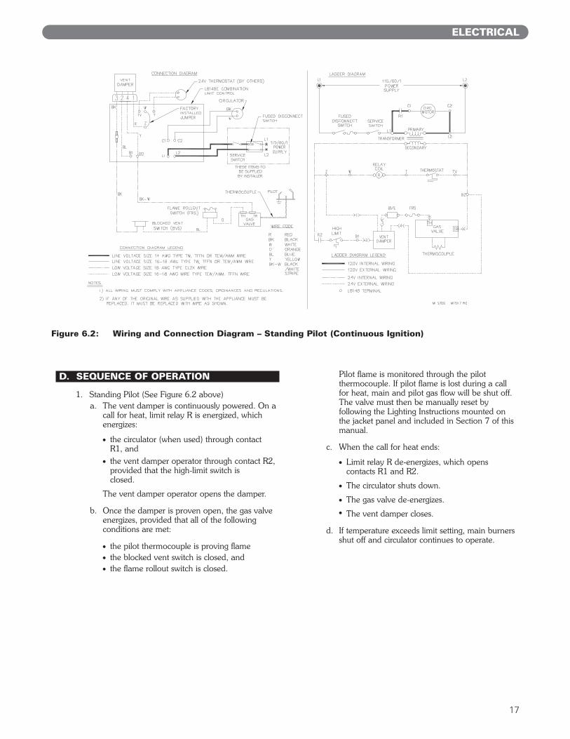
D. SEQUENCE OF OPERATION
1. Standing Pilot (See Figure 6.2 above)a. The vent damper is continuously powered. On a
call for heat, limit relay R is energized, whichenergizes:
● the circulator (when used) through contactR1, and
● the vent damper operator through contact R2,provided that the high-limit switch isclosed.
The vent damper operator opens the damper.
b. Once the damper is proven open, the gas valveenergizes, provided that all of the followingconditions are met:
● the pilot thermocouple is proving flame● the blocked vent switch is closed, and● the flame rollout switch is closed.
Pilot flame is monitored through the pilotthermocouple. If pilot flame is lost during a callfor heat, main and pilot gas flow will be shut off.The valve must then be manually reset byfollowing the Lighting Instructions mounted onthe jacket panel and included in Section 7 of thismanual.
c. When the call for heat ends:
● Limit relay R de-energizes, which opens contacts R1 and R2.
● The circulator shuts down.
● The gas valve de-energizes.● The vent damper closes.
d. If temperature exceeds limit setting, main burnersshut off and circulator continues to operate.
ELECTRICAL
Figure 6.2: Wiring and Connection Diagram – Standing Pilot (Continuous Ignition)
18
ELECTRICAL
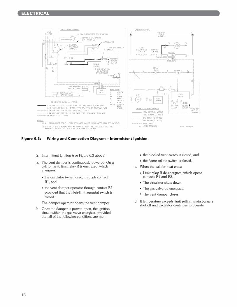
2. Intermittent Ignition (see Figure 6.3 above)
a. The vent damper is continuously powered. On acall for heat, limit relay R is energized, whichenergizes:
● the circulator (when used) through contactR1, and
● the vent damper operator through contact R2,provided that the high-limit aquastat switch isclosed.
The damper operator opens the vent damper.
b. Once the damper is proven open, the ignitioncircuit within the gas valve energizes, providedthat all of the following conditions are met:
● the blocked vent switch is closed, and
● the flame rollout switch is closed.
c. When the call for heat ends:
● Limit relay R de-energizes, which opens contacts R1 and R2.
● The circulator shuts down.
● The gas valve de-energizes.● The vent damper closes.
d. If temperature exceeds limit setting, main burnersshut off and circulator continues to operate.
Figure 6.3: Wiring and Connection Diagram – Intermittent Ignition
19
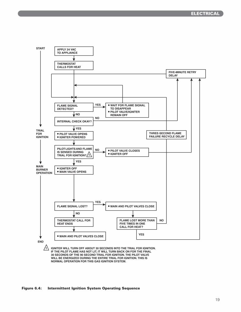
Figure 6.4: Intermittent Ignition System Operating Sequence
ELECTRICAL
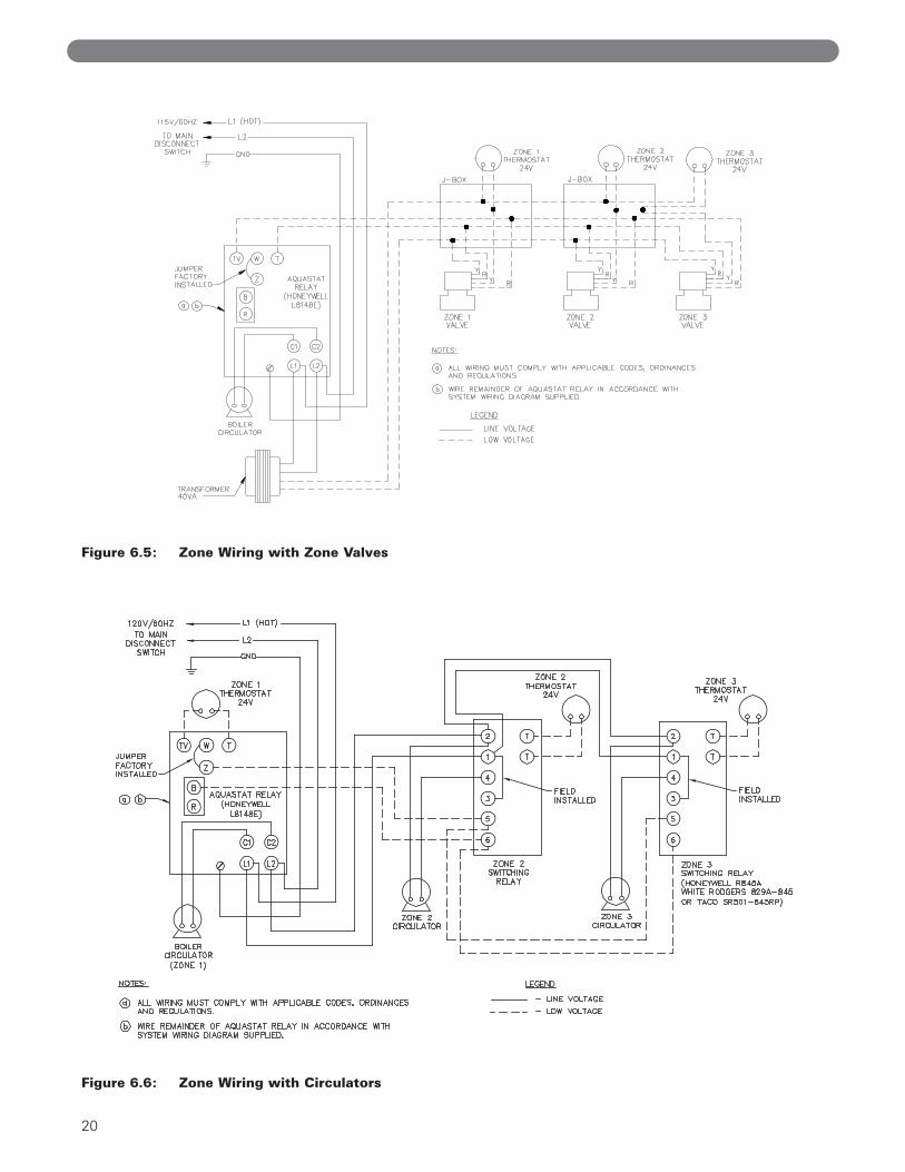
Figure 6.5: Zone Wiring with Zone Valves
Figure 6.6: Zone Wiring with Circulators
20

A. COMPLETING THE INSTALLATION
1. Confirm that all water, gas and electricity areturned off.
2. Inspect the boiler combustion chamber for foreignobjects and remove if present.
3. Check physical condition of burners and pilot. Makecertain that there are no unusual bends orperforations in the burners or pilot. Replacecomponents if necessary.
4. Verify that water piping, venting, gas piping andelectrical wiring and components are installedproperly. Refer back to previous sections of theseinstructions as well as equipment manufacturer’sinstructions as necessary.
5. Fill the boiler and system with water, making certainto vent all air from all points in the system. To checkwater level in the system, open and close each ventin the system. Water should exit from each ventwhen it is opened.
6. The pressure reducing valve on the fill line willtypically allow the system to be filled and pressurizedto 12 psi (83 kPa). Consult the valve and expansiontank manufacturer for more specific information.
7. Check joints and fittings throughout the system forleaks. If leaks are found, drain the system and repairas required.
8. Connect a manometer to the gas valve on the valveoutlet (gas manifold). Use the 1/8 NPT tappingprovided.
9. Confirm that the gas supply pressure to the boiler isabove the minimum and below the maximum valuesfor the gas being used. See the end of Section 5 forthese values. If a supply pressure check is required,isolate the boiler and gas valve before performingthe pressure check. If the supply pressure is too highor too low, contact the gas supplier.
10. Turn on electricity and gas to boiler.
11. Light the boiler by following the Lighting/OperatingInstructions label mounted to the jacket panel. Theinitial ignition may require several tries as the pipingis purged of air.
12. Use the sequence descriptions in Figures 6.2, 6.3and 6.4 in Section 6 (Electrical) to follow light-offand shutdown sequences and to assist in diagnosingproblems. If the boiler does not function properly,consult Section 8, Troubleshooting.
13. The gas manifold and control assembly are made ofgas-tight, completely factory assembled and installedcomponents of the base assembly. See Figure 7.1and 7.2.
21
START-UP PROCEDURES
7. START-UP PROCEDURES

22
Figure 7.1: Gas Valve, Manifold and Burner Assembly – Standing Pilot (Continuous Ignition)
Figure 7.2: Gas Valve, Manifold and Burner Assembly – Intermittent Ignition
Figure 7.3: Valve Tapping and Adjustment Screw Locations
START-UP PROCEDURES
23
START-UP PROCEDURES
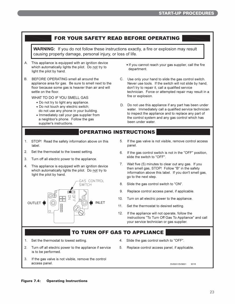
Figure 7.4: Operating Instructions

24
Figure 7.5: Lighting Instructions
START-UP PROCEDURES
H24V VR8200/VR8300 9177R
If you cannot reach your gas supplier, call the fire department.
C. Use only your hand to push in or turn the gas control knob. Never use tools. If the knob will not push in or turn by hand, don't try to repair it, call a qualified service technician. Force or attempted repair may result in a fire or explosion.
D. Do not use this appliance if any part has been under water. Immediately call a qualified service technician to inspect the appliance and to replace any part of the control system and any gas control which has been under water.
WARNING: If you do not follow these instructions exactly, a fire or explosion may
result causing property damage, personal injury, or loss of life.
FOR YOUR SAFETY READ BEFORE LIGHTING
LIGHTING INSTRUCTIONS
1. STOP! Read the safety information above on this label.
2. Set the thermostat to lowest setting.
3. Turn off all electric power to the appliance.
4. If the gas valve is not visible, remove control access
panel.
5. If the gas control knob is not in the "OFF" position, turn the knob clockwise to "OFF".
Gas Control Knob
(shown in "OFF"
position)Red Reset Button
6. Wait five (5) minutes to clear out any gas. Then smell
for gas, including near the floor. If you smell gas,
STOP! Follow "B" in the safety information above on
this label. If you don't smell gas, go to the next step.
7. Remove the pilot access panel, if supplied, located
below and behind the gas valve directly above burner
tubes.
TO TURN OFF GAS TO APPLIANCE
8. Find pilot - follow metal tube from gas valve. The pilot is between two burner tubes
Pilot Burner
9. Turn the gas control knob counterclockwise to
"PILOT".
10. Push in red reset button all the way and hold in.
Immediately light the pilot with a match. Continue to
hold the reset button in for about one (1) minute after
the pilot is lit. Release button and it will pop back up.
Pilot should remain lit. If it goes out, repeat steps 5
through 10.
If button does not pop up when released, stop and
immediately call your service technician or gas
supplier.
If the pilot will not stay lit after several tries, turn the
gas control knob to "OFF" and call your service
technician or gas supplier.
11. Replace pilot access panel, if applicable.
12. Turn gas control knob counterclockwise to "ON".
13. Replace control access panel, if applicable.
14. Turn on all electric power to the appliance.
15. Set thermostat to desired setting.
1. Set the thermostat to lowest setting.
2. Turn off all electric power to the appliance if service is to be performed.
3. If the gas valve is not visible, remove the control access panel.
4. Turn the gas control knob clockwise to "OFF".
5. Replace control access panel, if applicable.
A. This appliance has a pilot which must be lighted by hand. When lighting the pilot, follow these instructions exactly.
B. BEFORE LIGHTING smell all around the appliance area for gas. Be sure to smell next to the floor because some gas is heavier than air and will settle on the floor.
WHAT TO DO IF YOU SMELL GAS Do not try to light any appliance Do not touch any electric switch; do not use any phone in your building Immediately call your gas supplier from a neighbor's phone. Follow the gas supplier's instruction.
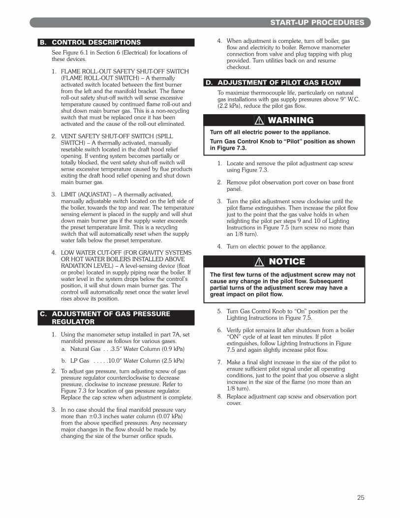
B. CONTROL DESCRIPTIONSSee Figure 6.1 in Section 6 (Electrical) for locations ofthese devices.
1. FLAME ROLL-OUT SAFETY SHUT-OFF SWITCH(FLAME ROLL-OUT SWITCH) – A thermallyactivated switch located between the first burnerfrom the left and the manifold bracket. The flameroll-out safety shut-off switch will sense excessivetemperature caused by continued flame roll-out andshut down main burner gas. This is a non-recyclingswitch that must be replaced once it has beenactivated and the cause of the roll-out eliminated.
2. VENT SAFETY SHUT-OFF SWITCH (SPILLSWITCH) – A thermally activated, manuallyresetable switch located in the draft hood reliefopening. If venting system becomes partially ortotally blocked, the vent safety shut-off switch willsense excessive temperature caused by flue productsexiting the draft hood relief opening and shut downmain burner gas.
3. LIMIT (AQUASTAT) – A thermally activated,manually adjustable switch located on the left side ofthe boiler, towards the top and rear. The temperaturesensing element is placed in the supply and will shutdown main burner gas if the supply water exceedsthe preset temperature limit. This is a recyclingswitch that will automatically reset when the supplywater falls below the preset temperature.
4. LOW WATER CUT-OFF (FOR GRAVITY SYSTEMSOR HOT WATER BOILERS INSTALLED ABOVERADIATION LEVEL) – A level-sensing device (floator probe) located in supply piping near the boiler. Ifwater level in the system drops below the control’sposition, it will shut down main burner gas. Thecontrol will automatically reset once the water levelrises above its position.
C. ADJUSTMENT OF GAS PRESSUREREGULATOR
1. Using the manometer setup installed in part 7A, setmanifold pressure as follows for various gases.a. Natural Gas . . .3.5″ Water Column (0.9 kPa)
b. LP Gas . . . . .10.0″ Water Column (2.5 kPa)
2. To adjust gas pressure, turn adjusting screw of gaspressure regulator counterclockwise to decreasepressure, clockwise to increase pressure. Refer toFigure 7.3 for location of gas pressure regulator.Replace the cap screw when adjustment is complete.
3. In no case should the final manifold pressure varymore than ±0.3 inches water column (0.07 kPa)from the above specified pressures. Any necessarymajor changes in the flow should be made bychanging the size of the burner orifice spuds.
4. When adjustment is complete, turn off boiler, gasflow and electricity to boiler. Remove manometerconnection from valve and plug tapping with plugprovided. Turn utilities back on and resumecheckout. GAS FLOW
D. ADJUSTMENT OF PILOT GAS FLOWTo maximize thermocouple life, particularly on naturalgas installations with gas supply pressures above 9″ W.C.(2.2 kPa), reduce the pilot gas flow.
1. Locate and remove the pilot adjustment cap screwusing Figure 7.3.
2. Remove pilot observation port cover on base frontpanel.
3. Turn the pilot adjustment screw clockwise until thepilot flame extinguishes. Then increase the pilot flowjust to the point that the gas valve holds in whenrelighting the pilot per steps 9 and 10 of LightingInstructions in Figure 7.5 (turn screw no more thanan 1/8 turn).
4. Turn on electric power to the appliance.
5. Turn Gas Control Knob to “On” position per theLighting Instructions in Figure 7.5.
6. Verify pilot remains lit after shutdown from a boiler“ON” cycle of at least ten minutes. If pilotextinguishes, follow Lighting Instructions in Figure7.5 and again slightly increase pilot flow.
7. Make a final slight increase in the size of the pilot toensure sufficient pilot signal under all operatingconditions, just to the point that you observe a slightincrease in the size of the flame (no more than an1/8 turn).
8. Replace adjustment cap screw and observation portcover.
25
START-UP PROCEDURES
Turn off all electric power to the appliance.
Turn Gas Control Knob to “Pilot” position as shownin Figure 7.3.
WARNING
The first few turns of the adjustment screw may notcause any change in the pilot flow. Subsequentpartial turns of the adjustment screw may have agreat impact on pilot flow.
NOTICE

26
E. CHECKING BURNER INPUT
1. Refer to rating label mounted on the jacket top panelto obtain the rated BTU per hour input. In no caseshall the input to the boiler exceed the value shownon the rating label.
2. Check input by use of the following formulas (PB Heat, LLC suggests reading meter for 2 Cu. Ft.):
U.S. Customary UnitsInput (BTU/Hr.)= 3600 x F x H
TWhere:3600 = Seconds per hour
F = Cubic Feet of Gas Registered on MeterH = Heat Value of Gas in BTU/Cubic FeetT = Time in Seconds the Meter is Read
SI Metric UnitsInput (kW)= 3600 x F x H
T x 3.6Where:3600 = Seconds per hour
3.6 = Megajoule (MJ) per kilowatt hour (kwhr)F = Cubic Meters of Gas Registered on MeterH = Heating Value of Gas in MJ/Cubic MeterT = Time in Seconds the Meter is Read
3. As an alternative, use Table 7.1(a) and 7.1(b). Usethe heating value provided by gas supplier. Use astopwatch to record the time it takes for 2 cubic feet(0.0566 cubic meter) of gas to pass through themeter. Read across and down to determine rate.
Burner inputs in Btu/hr for various meter timings and heatvalues. (Table based on 2 cubic feet of gas through meter).
Burner inputs in kW for for various meter timings and heat values. (Table based on 0.0566 cubic meter of gasthrough meter).
F. CHECK-OUT PROCEDURE
1. After starting the boiler, be certain all controls areworking properly. Check to be sure that the limit willshut off the boiler in the event of excessive watertemperature. This can be done by lowering the limitsetting until the main burners shut down. Whenproper limit function is confirmed, return the dial toits previous setting.
2. To check operation of the ignition system safetyshut-off features:a. Standing Pilot:
i) Turn the gas control knob counterclockwise to“PILOT”. The main burner should go outand the pilot should remain lit.
ii) Extinguish the pilot flame. Pilot gas flowshould stop within 2-1/2 minutes. Completeshutdown is proven since the safety shut-offvalve has stopped main and pilot gas flow.
iii) Reset the boiler by following LightingInstructions.
iv) Observe boiler operation through onecomplete cycle.
START-UP PROCEDURES
2880002400002057141800001600001440001309091200001107691028579600090000847068000075789720006857165455626096000057600
253035404550556065707580859095
100105110115120125
2952002460002108571845001640001476001341821230001135381054299840092250868248200077684738007028667091641746150059040
30240025200021600018900016800015120013745512600011630810800010080094500889418400079579756007200068727657396300060480
Heat Value of Gas(Btu/cubic foot)
1000 1025 1050
Time thatmeter is
read (sec)
Table 7.1a: Meter Conversion – Natural Gas (U.S. Customary Units)
Time thatmeter is
read (sec)
Heat Value of Gas(MJ/cubic meter)
37.26 38.19 39.12
253035404550556065707580859095
100105110115120125
84.3670.3060.2552.7246.8642.1838.3435.1532.4430.1328.1226.3624.8123.4322.2021.0920.0819.1718.3417.5716.87
86.4672.0561.7654.0448.0343.2339.3036.0333.2530.8828.8227.0225.4324.0222.7521.6220.5919.6518.8018.0117.29
88.5773.8163.2655.3549.2044.2840.2636.9034.0631.6329.5227.6826.0524.6023.3122.1421.0920.1319.2518.4517.71
Table 7.1b: Meter Conversion – Natural Gas (SI Metric Units)

27
b. Intermittent Ignition System:
i) Turn gas supply off.
ii) Set thermostat or controller above roomtemperature to call for heat. Watch for igniterglow at pilot burner.
iii) Igniter will continue to glow for 30 seconds,de-energize for 30 seconds, then re-energizeand glow for another 30 seconds. It will thende-energize for 5 minutes before restartingthe sequence.
iv) Turn gas supply on.
v) Reset the boiler and control by followingOperating Instructions.
vi) Observe boiler operation through onecomplete cycle.
3. Low Water Cut-Off (if used) – Consult themanufacturer’s instructions for the low water cut-offoperational check procedure.
4. Check the system to make sure there are no leaks oroverfilling problems which might cause excessivemake-up water to be added. Make-up water causesliming in the boiler and brings in oxygen. Oxygencan cause severe damage to the boiler thoughoxygen corrosion pitting.
5. Check the expansion tank and automatic fill valve (ifused) to confirm that they are operating correctly. Ifeither of these components causes high pressure inthe system, the boiler relief valve will weep or open,allowing fresh water to enter the system.
6. Do not allow the system controls to subject the boilerto excessively low water temperatures, which wouldcause condensation of flue gases and corrosion ofthe boiler. Operate the boiler at a temperature above130°F (54°C). Adjust the boiler limit as required tomaintain boiler temperature above this level.
7. Check the general condition of the system includingpiping support, joints, etc. Check cleanliness of theradiators, baseboard units and/or convectors. Cleanthem to the extent possible. If radiators do not heatevenly, vent any remaining air from them.
8. Review operation and User’s Information Manualwith end-user.
9. Complete the Warranty Card and submit it to PB Heat, LLC.
10. Hang the Installation, Operation and MaintenanceManual and User’s Information Manual in anaccessible position near the boiler.
START-UP PROCEDURES

A. SHUT-DOWN CAUSED BY PILOT OUTAGE, BLOCKED VENT SHUT-OFFSWITCH OR FLAME ROLL-OUT SAFETY SHUT-OFF SWITCHIn the event of a shut-down caused by a pilot outage,action of the blocked vent shut-off switch or flame roll-out safety shut-off switch effecting a shut-down of themain burners:
a. Refer to the Lighting/Operating Instructions inFigures 7.4 and 7.5 to properly turn off the gas tothe boiler.
b. Turn off all electric power to the boiler.c. Call a qualified heating service organization or local
gas company and have the cause of the shut-downinvestigated and corrected.
d. Refer to Lighting/Operating Instructions tore-start boiler.
B. TROUBLESHOOTING GUIDES
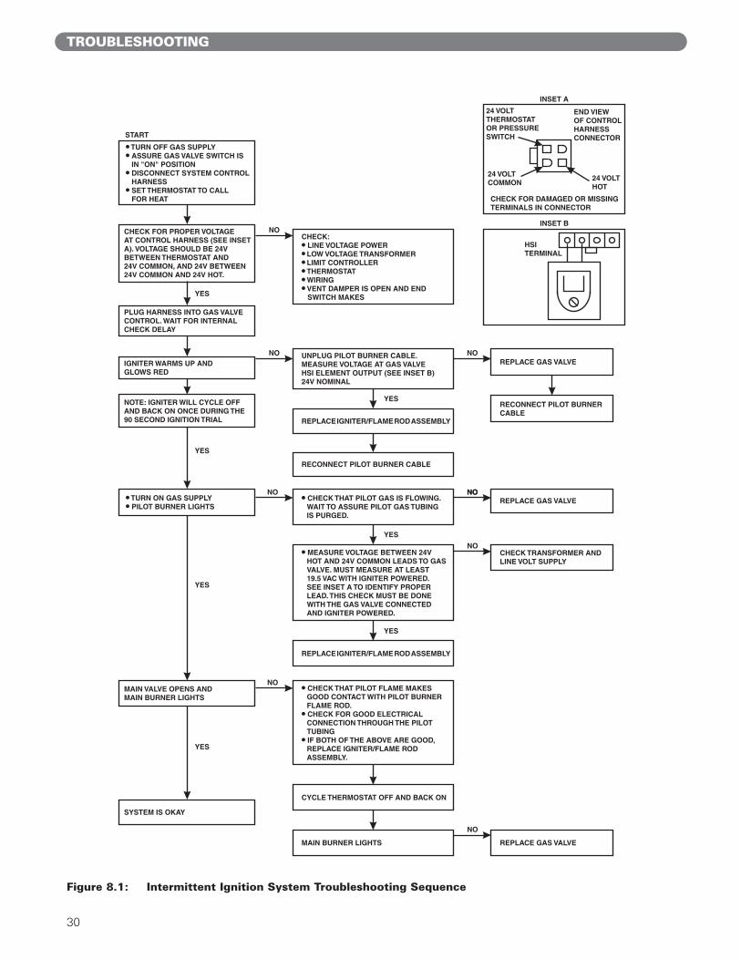
Use Table 8.1 to assist in determining causes andproviding corrective actions to boiler problems. Referalso to Figure 8.1 to troubleshoot the IntermittentIgnition System Control. These guides must be usedonly by qualified service technicians. These individualsmust follow all applicable codes and regulations in repairof any boiler problems.
TROUBLESHOOTING
8. TROUBLESHOOTING
Should overheating occur or the gas supply fail toshut off, do not turn off or disconnect the electricalsupply to the pump. This may aggravate the problemand increase the likelihood of boiler damage. Instead,shut off the gas supply at a location external to theappliance.
CAUTION
Do not use this appliance if any part has been underwater. Improper or dangerous operation may result.Immediately call a qualified service technician toinspect the boiler and to replace any part of thecontrol system and any gas control which has beenunder water.
WARNING
Label all wires prior to disconnection when servicingcontrols. Wiring errors can cause improper anddangerous operation. Verify proper operation afterservicing.
CAUTION
When servicing or replacing items that communicatewith the boiler water, be certain that:
● There is no pressure on the boiler.● The boiler is not hot.● The power is off.
When servicing the gas valve or pilot, be certain that:● The gas is off.● The electricity is off.
DANGER
28

29
TROUBLESHOOTING
Table 8.1: Boiler Troubleshooting Guide
PROBLEM POSSIBLE CAUSES CORRECTIVE ACTIONS
1. No power.2. Limit (Aquastat) not working.
3. Flame rollout switch open.4. Blocked vent switch open.5. Gas off at boiler gas valve.
6. Gas off external to boiler.7. Plugged orifice spuds.8. Defective gas valve.
9. Improper wiring.
10. Vent damper malfunctioning.
Burners not functioning. 1. Check line voltage wiring and fuses.2. Check wiring and contacts, relay, temperature
setting. Clean and adjust as necessary.3. Replace switch. Locate cause and correct.4. Reset blocked vent switch. Locate cause and correct.5. Start boiler using Lighting/Operating
Instructions.6. Check any gas valves in the line.7. Check, clean and re-install.8. Use Figure 8.1 to troubleshoot intermittent
ignition gas valve. Replace if necessary.9. Check and correct in accordance with wiring
diagrams in Section 6.10. Refer to vent damper manufacturer’s instructions.
Replace if necessary.
1. Defective gas valve.
2. Short circuit.
Burners will not shutdown.
1. Use Figure 8.1 to troubleshoot intermittentignition gas valve. Replace if necessary.
2. Check and correct wiring.
1. Manifold gas pressure too low.2. Improperly sized/drilled orifice spuds.3. Leaking gas valve.4. Burrs on orifice.5. Low supply gas pressure.
6. Excessive downdraft or draft problems inboiler room.
Flashback or burningat orifice spuds.
1. Adjust to proper pressure.2. Install correct spuds.3. Replace valve.4. Remove burrs.5. Contact gas supplier if natural gas. Adjust
regulator if LP gas.6. Check air supply, ventilation and venting system.
1. Insufficient pilot flame.2. Pilot burner/orifice clogged.3. Overfiring.4. Misaligned burners or pilot.5. Draft problem in boiler room.
Delayed ignition. 1. Increase pilot gas flow.2. Clean pilot burner and orifice.3. Reduce rate to input on rating label.4. Realign burners or pilot.5. Check air supply, ventilation and venting
system.
1. Underfiring.2. Limit (Aquastat) set too low.3. Vent pipe too long.4. Inadequate chimney or venting system.
Excessive condensation invent.
1. Increase rate to input on rating label.2. Reset Aquastat to higher setting.3. Reposition boiler to reduce length.4. Check chimney and venting recommendations.
1. Underfiring.2. Limit set too low.3. Air in system.4. Circulator malfunctioning.5. Circulation system clogged.
6. Incorrect thermostat heat anticipator setting.
Boiler not heatingproperly.
1. Increase rate to input on rating label.2. Reset Aquastat to higher setting.3. Vent air from all points in system.4. Check circulator, replace if necessary.5. Shut down and cool boiler, drain and flush
system.6. Adjust heat anticipator.
1. Leaks in gas piping or fittings.2. Leaks in gas service line or meter.3. Obstructed chimney.4. Obstructed flueways or vent.5. Undersized chimney or vent, high draft loss
in vent.6. Draft problem in boiler room.7. Overfiring.8. Vent damper malfunctioning.
Fumes or gas odors 1. Locate and repair or replace.2. Shut down boiler and notify gas provider.3. Check, repair and/or clean chimney.4. Clean flueways or vent and remove obstructions.5. Check National Fuel Gas Code and vent
manufacturer’s recommendations.6. Check air supply, ventilation and venting system.7. Reduce rate to input on rating label.8. Refer to vent damper manufacturer’s instructions.
Replace if necessary.
30
Figure 8.1: Intermittent Ignition System Troubleshooting Sequence
TROUBLESHOOTING
31
MAINTENANCE
9. MAINTENANCE
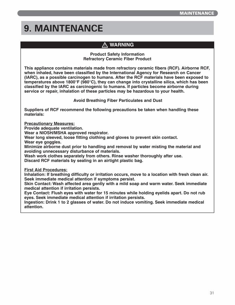
WARNING
Product Safety InformationRefractory Ceramic Fiber Product
This appliance contains materials made from refractory ceramic fibers (RCF). Airborne RCF,when inhaled, have been classified by the International Agency for Research on Cancer(IARC), as a possible carcinogen to humans. After the RCF materials have been exposed totemperatures above 1800°F (980°C), they can change into crystalline silica, which has beenclassified by the IARC as carcinogenic to humans. If particles become airborne during service or repair, inhalation of these particles may be hazardous to your health.
Avoid Breathing Fiber Particulates and Dust
Suppliers of RCF recommend the following precautions be taken when handling these materials:
Precautionary Measures:Provide adequate ventilation.Wear a NIOSH/MSHA approved respirator.Wear long sleeved, loose fitting clothing and gloves to prevent skin contact.Wear eye goggles.Minimize airborne dust prior to handling and removal by water misting the material andavoiding unnecessary disturbance of materials. Wash work clothes separately from others. Rinse washer thoroughly after use.Discard RCF materials by sealing in an airtight plastic bag.
First Aid Procedures:Inhalation: If breathing difficulty or irritation occurs, move to a location with fresh clean air.Seek immediate medical attention if symptoms persist.Skin Contact: Wash affected area gently with a mild soap and warm water. Seek immediatemedical attention if irritation persists.Eye Contact: Flush eyes with water for 15 minutes while holding eyelids apart. Do not rubeyes. Seek immediate medical attention if irritation persists.Ingestion: Drink 1 to 2 glasses of water. Do not induce vomiting. Seek immediate medicalattention.
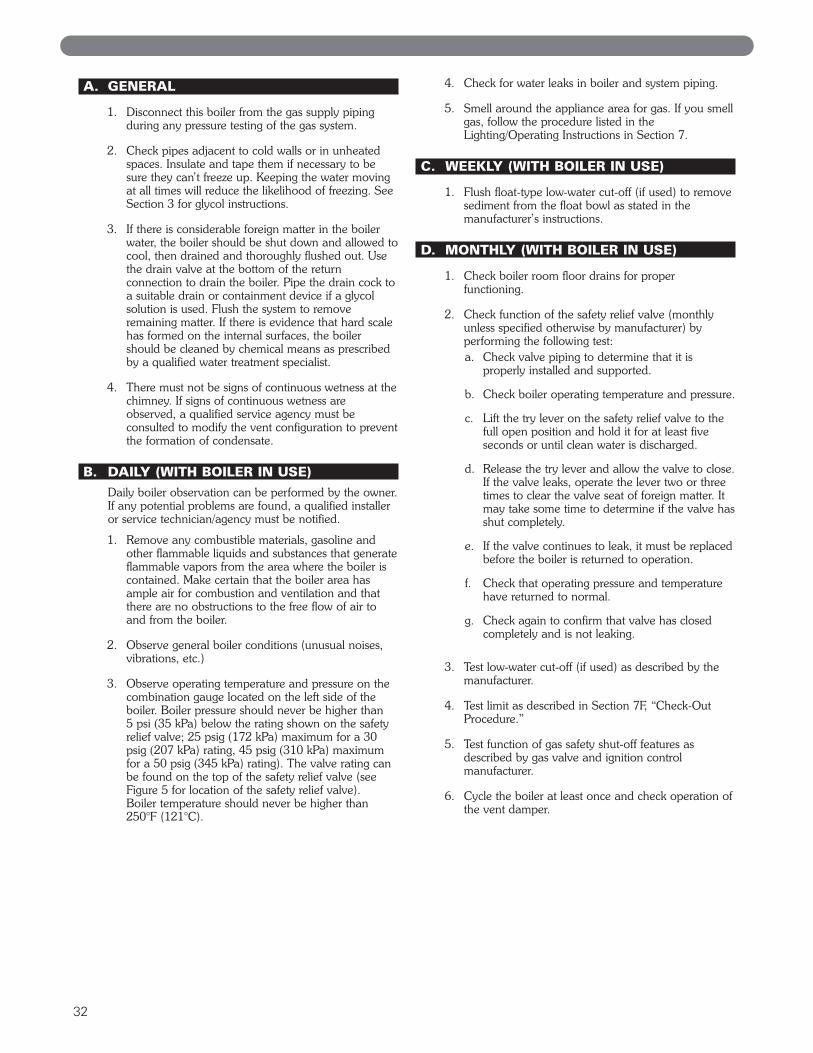
A. GENERAL
1. Disconnect this boiler from the gas supply pipingduring any pressure testing of the gas system.
2. Check pipes adjacent to cold walls or in unheatedspaces. Insulate and tape them if necessary to besure they can’t freeze up. Keeping the water movingat all times will reduce the likelihood of freezing. SeeSection 3 for glycol instructions.
3. If there is considerable foreign matter in the boilerwater, the boiler should be shut down and allowed tocool, then drained and thoroughly flushed out. Usethe drain valve at the bottom of the returnconnection to drain the boiler. Pipe the drain cock toa suitable drain or containment device if a glycolsolution is used. Flush the system to removeremaining matter. If there is evidence that hard scalehas formed on the internal surfaces, the boilershould be cleaned by chemical means as prescribedby a qualified water treatment specialist.
4. There must not be signs of continuous wetness at thechimney. If signs of continuous wetness areobserved, a qualified service agency must beconsulted to modify the vent configuration to preventthe formation of condensate.
B. DAILY (WITH BOILER IN USE)Daily boiler observation can be performed by the owner.If any potential problems are found, a qualified installeror service technician/agency must be notified.
1. Remove any combustible materials, gasoline andother flammable liquids and substances that generateflammable vapors from the area where the boiler iscontained. Make certain that the boiler area hasample air for combustion and ventilation and thatthere are no obstructions to the free flow of air toand from the boiler.
2. Observe general boiler conditions (unusual noises,vibrations, etc.)
3. Observe operating temperature and pressure on thecombination gauge located on the left side of theboiler. Boiler pressure should never be higher than5 psi (35 kPa) below the rating shown on the safetyrelief valve; 25 psig (172 kPa) maximum for a 30psig (207 kPa) rating, 45 psig (310 kPa) maximumfor a 50 psig (345 kPa) rating). The valve rating canbe found on the top of the safety relief valve (seeFigure 5 for location of the safety relief valve). Boiler temperature should never be higher than250°F (121°C).
4. Check for water leaks in boiler and system piping.
5. Smell around the appliance area for gas. If you smellgas, follow the procedure listed in theLighting/Operating Instructions in Section 7.
C. WEEKLY (WITH BOILER IN USE)
1. Flush float-type low-water cut-off (if used) to removesediment from the float bowl as stated in themanufacturer’s instructions.
D. MONTHLY (WITH BOILER IN USE)
1. Check boiler room floor drains for properfunctioning.
2. Check function of the safety relief valve (monthlyunless specified otherwise by manufacturer) byperforming the following test:a. Check valve piping to determine that it is
properly installed and supported.
b. Check boiler operating temperature and pressure.
c. Lift the try lever on the safety relief valve to thefull open position and hold it for at least fiveseconds or until clean water is discharged.
d. Release the try lever and allow the valve to close.If the valve leaks, operate the lever two or threetimes to clear the valve seat of foreign matter. Itmay take some time to determine if the valve hasshut completely.
e. If the valve continues to leak, it must be replacedbefore the boiler is returned to operation.
f. Check that operating pressure and temperaturehave returned to normal.
g. Check again to confirm that valve has closedcompletely and is not leaking.
3. Test low-water cut-off (if used) as described by themanufacturer.
4. Test limit as described in Section 7F, “Check-OutProcedure.”
5. Test function of gas safety shut-off features asdescribed by gas valve and ignition controlmanufacturer.
6. Cycle the boiler at least once and check operation ofthe vent damper.
32

33
E. ANNUALLY (BEFORE START OF HEATINGSEASON)
1. Check flueways and burners for cleanliness and cleanif necessary. Use the following procedure if cleaningis required:
a. Refer to the Lighting/Operating Instructions inFigures 7.4 and 7.5 to properly turn off the gas tothe boiler.
b. Turn off all electrical power to the boiler.
c. Remove burners and brush orifice spuds lightlyusing a soft bristle brush.
d. Remove the vent pipe, vent damper, top jacketpanels and flue collector/draft diverter. Removebaffles on MIH™ models.
e. Brush flueways with wire brush.
f. To the extent possible, inspect inside of vent pipeand vent damper for obstructions in flow or ventdamper movement. Remove or replace asnecessary.
g. Re-install baffles on MIH™ models. Whenreplacing the flue collector/draft hood, be certainthat the blanket seal between the flue collectorand top section makes a tight seal to preventleakage of the products of combustion.
h. Re-install the top of the jacket, vent damper andvent pipe.
i. Re-install burners.
2. Inspect entire venting system for corrosion, supportand joint integrity. Repair as necessary.
3. Check the pilot and main burner flame. See Figures9.1 and 9.2. The pilot should provide a steady flameenveloping 3/8″ to 1/2″ (1 cm to 1.2 cm) of theflame sensor. If required, adjust the pilot as stated inthe gas valve manufacturer’s instructions orparagraph 7.D. The main burner flame inner coneshould be approximately 1-1/2″ (4 cm) high andshould have a very sharp, blue color characteristic.
MAINTENANCE
Figure 9.1: Standing Pilot and Main BurnerFlame
Figure 9.2: Intermittent Pilot and MainBurner Flame
When servicing or replacing components, beabsolutely certain that the following conditions aremet:
● Water, gas and electricity are off.● The boiler is at room temperature.● There is no pressure in the boiler.
DANGER
BOILER DIMENSIONS & RATINGS
34
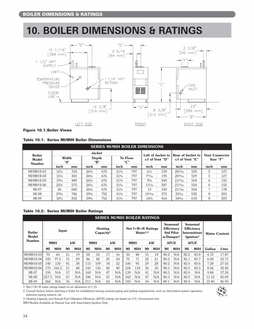
10. BOILER DIMENSIONS & RATINGS
Table 10.2: Series MI/MIH Boiler Ratings
1 Net I=B=R water ratings based on an allowance of 1.15.2 Consult factory before selecting a boiler for installations having unusual piping and pickup requirements, such as intermittent system operation,
extensive piping systems, etc.3 Heating Capacity and Annual Fuel Utilization Efficiency (AFUE) ratings are based on U.S. Government test.MIH Models Available as Natural Gas with Intermittent Ignition Only.
Table 10.1: Series MI/MIH Boiler Dimensions
SERIES MI/MIH BOILER DIMENSIONS
BoilerModel
Number
JacketLeft of Jacket toc/l of Vent “D”
Rear of Jacket toc/l of Vent “E”
Vent ConnectorSize “F”Width
“A”Depth“B”
To Floor“C”
inch mm inch mm inch mm inch mm inch mm inch mmMI/MIH II-03 12¹⁄₂ 318 26⁵⁄₈ 676 31³⁄₈ 797 6¹⁄₄ 159 20¹³⁄₁₆ 529 5 127MI/MIH II-04 15⁷⁄₈ 403 26⁵⁄₈ 676 31³⁄₈ 797 7¹¹⁄₁₆ 195 20¹³⁄₁₆ 529 5 127MI/MIH II-05 19¹⁄₄ 489 26⁵⁄₈ 676 31³⁄₈ 797 9⁵⁄₈ 244 21¹³⁄₁₆ 554 6 152MI/MIH II-06 22⁵⁄₈ 575 26⁵⁄₈ 676 31³⁄₈ 797 11⁵⁄₁₆ 287 21¹³⁄₁₆ 554 6 152
MI-07 26 660 26⁵⁄₈ 676 31³⁄₈ 797 13 330 21¹³⁄₁₆ 554 7 178MI-08 29³⁄₈ 746 29⁵⁄₈ 752 31³⁄₈ 797 14¹¹⁄₁₆ 373 23⁵⁄₁₆ 592 8 203MI-09 32³⁄₄ 832 29⁵⁄₈ 752 31³⁄₈ 797 16³⁄₈ 416 24⁵⁄₁₆ 618 8 203
SERIES MI/MIH BOILER RATINGS
BoilerModel
Number
InputHeating
Capacity³Net I=B=R Ratings
Water¹,²
SeasonalEfficiencyStd Pilot
w/Damper³
SeasonalEfficiency
IntermittentIgnition³
Water Content
MBH kW MBH kW MBH kW AFUE AFUE
MI MIH MI MIH MI MIH MI MIH MI MIH MI MIH MI MIH MI MIH Gallon Liter
MI/MIH II-03 70 65 21 19 58 55 17 16 50 48 15 14 80.2 N/A 82.2 83.8 4.72 17.87MI/MIH II-04 105 97.5 31 29 86 82 25 24 75 71 22 21 80.2 N/A 82.1 83.7 6.00 22.71MI/MIH II-05 140 130 41 38 115 109 34 32 100 95 29 28 80.2 N/A 82.0 83.6 7.28 27.55MI/MIH II-06 175 162.5 51 48 143 136 42 40 124 118 36 35 80.3 N/A 82.0 83.5 8.56 32.40
MI-07 195 N/A 57 N/A 160 N/A 47 N/A 139 N/A 41 N/A 80.5 N/A 82.0 N/A 9.84 37.24MI-08 227.5 N/A 67 N/A 186 N/A 55 N/A 162 N/A 47 N/A 80.3 N/A 82.0 N/A 11.12 42.09MI-09 260 N/A 76 N/A 211 N/A 62 N/A 183 N/A 54 N/A 80.1 N/A 82.0 N/A 12.40 46.93
Figure 10.1:Boiler Views

35
BOILER DIMENSIONS & RATINGS
Figure 11.1: Base/Combustible Floor Pan
REPAIR PARTSSERIES MI/MIH™ GAS BOILER
Repair parts are available from your installer or by contacting PB Heat, LLC, 131 S. ChurchSt., Bally, PA 19503. Use the figures and tables on pages 35-41 to assist in ordering parts.
Note: Remember to include boiler model number and serial number when ordering parts.
11. REPAIR PARTS
Table 11.1: Base/Combustible Floor Pan
Description QuantityRequired
StockCode
1
Base Assembly – MI-03 – 7800Base Assembly – MI-04 – 7801Base Assembly – MI-05 – 7802Base Assembly – MI-06 – 7803Base Assembly – MI-07 – 7804Base Assembly – MI-08 – 7805Base Assembly – MI-09 – 7806
2 Observation Cover Door – 517713 Base Blanket Seal – 50867
4
Combustible Floor Pan Assembly – MI-03 – 90700Combustible Floor Pan Assembly – MI-04 – 90701Combustible Floor Pan Assembly – MI-05 – 90702Combustible Floor Pan Assembly – MI-06 – 90703Combustible Floor Pan Assembly – MI-07 – 90704Combustible Floor Pan Assembly – MI-08 – 90705Combustible Floor Pan Assembly – MI-09 – 90706

REPAIR PARTS
36
Figure 11.2: Manifold
Figure 11.3b: Gas Valve and Pilot (Intermittent Ignition)
Figure 11.3a: Gas Valve and Pilot – Standing Pilot (Continuous Ignition)
37
REPAIR PARTS
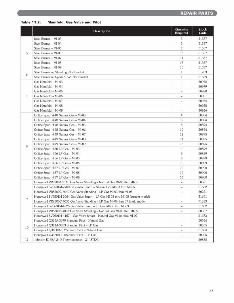
Table 11.2: Manifold, Gas Valve and Pilot
Description QuantityRequired
StockCode
5
Steel Burner – MI-03 3 51537
Steel Burner – MI-04 5 51537
Steel Burner – MI-05 7 51537
Steel Burner – MI-06 9 51537
Steel Burner – MI-07 11 51537
Steel Burner – MI-08 13 51537
Steel Burner – MI-09 15 51537
6Steel Burner w/ Standing Pilot Bracket 1 51263
Steel Burner w/ Spark & SV Pilot Bracket 1 51539
7
Gas Manifold – MI-03 – 50978
Gas Manifold – MI-04 – 50979
Gas Manifold – MI-05 – 50980
Gas Manifold – MI-06 – 50981
Gas Manifold – MI-07 – 50954
Gas Manifold – MI-08 – 50955
Gas Manifold – MI-09 – 50956
8
Orifice Spud, #48 Natural Gas – MI-03 4 50894
Orifice Spud, #48 Natural Gas – MI-04 6 50894
Orifice Spud, #48 Natural Gas – MI-05 8 50894
Orifice Spud, #48 Natural Gas – MI-06 10 50894
Orifice Spud, #49 Natural Gas – MI-07 12 50895
Orifice Spud, #49 Natural Gas – MI-08 14 50895
Orifice Spud, #49 Natural Gas – MI-09 16 50895
Orifice Spud, #56 LP Gas – MI-03 4 50899
Orifice Spud, #56 LP Gas – MI-04 6 50899
Orifice Spud, #56 LP Gas – MI-05 8 50899
Orifice Spud, #56 LP Gas – MI-06 10 50899
Orifice Spud, #57 LP Gas – MI-07 12 50900
Orifice Spud, #57 LP Gas – MI-08 14 50900
Orifice Spud, #57 LP Gas – MI-09 16 50900
9
Honeywell VR8200A-2116 Gas Valve Standing – Natural Gas MI-03 thru MI-05 – 50581
Honeywell SV9501M-2700 Gas Valve Smart – Natural Gas MI-03 thru MI-05 – 51682
Honeywell VR8200C-6040 Gas Valve Standing – LP Gas MI-03 thru MI-05 – 50221
Honeywell SV9501M-2064 Gas Valve Smart – LP Gas MI-03 thru MI-05 (current model) – 51691
Honeywell VR8300C-4035 Gas Valve Standing – LP Gas MI-06 thru 09 (early model) – 91333
Honeywell SV9601M-4225 Gas Valve Smart – LP Gas MI-06 thru MI-09 – 51692
Honeywell VR8300A-4003 Gas Valve Standing – Natural Gas MI-06 thru MI-09 – 50587
Honeywell SV9601M-4167 – Gas Valve Smart – Natural Gas MI-06 thru MI-09 – 51683
10
Honeywell Q314A-3679 Standing Pilot – Natural Gas – 50554
Honeywell Q314A-3703 Standing Pilot – LP Gas – 50555
Honeywell Q3480B-1025 Smart Pilot – Natural Gas – 51684
Honeywell Q3480B-1058 Smart Pilot – LP Gas – 50205
11 Johnson K16BA-24D Thermocouple – 24" STDG – 50838

38
Figure 11.4: Block/Draft Hood
Figure 11.5: Jacket
REPAIR PARTS
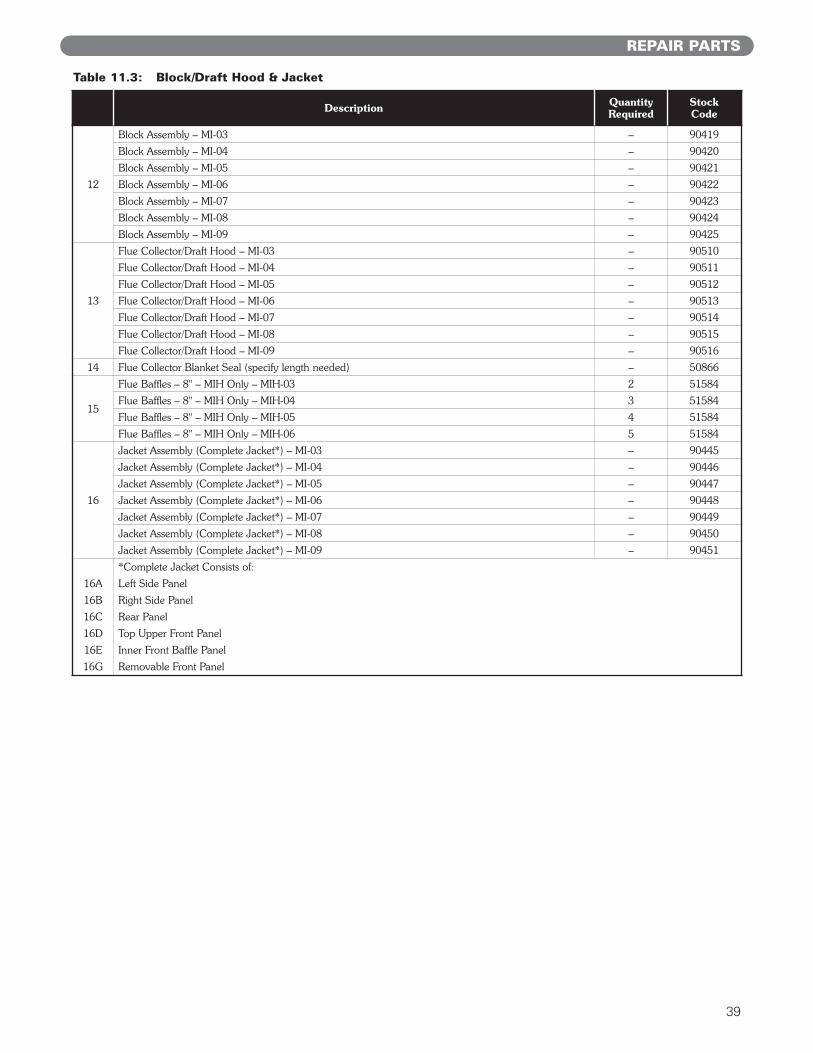
Table 11.3: Block/Draft Hood & Jacket
39
Description QuantityRequired
StockCode
12
Block Assembly – MI-03 – 90419
Block Assembly – MI-04 – 90420
Block Assembly – MI-05 – 90421
Block Assembly – MI-06 – 90422
Block Assembly – MI-07 – 90423
Block Assembly – MI-08 – 90424
Block Assembly – MI-09 – 90425
13
Flue Collector/Draft Hood – MI-03 – 90510
Flue Collector/Draft Hood – MI-04 – 90511
Flue Collector/Draft Hood – MI-05 – 90512
Flue Collector/Draft Hood – MI-06 – 90513
Flue Collector/Draft Hood – MI-07 – 90514
Flue Collector/Draft Hood – MI-08 – 90515
Flue Collector/Draft Hood – MI-09 – 90516
14 Flue Collector Blanket Seal (specify length needed) – 50866
15
Flue Baffles – 8" – MIH Only – MIH-03 2 51584
Flue Baffles – 8" – MIH Only – MIH-04 3 51584
Flue Baffles – 8" – MIH Only – MIH-05 4 51584
Flue Baffles – 8" – MIH Only – MIH-06 5 51584
16
Jacket Assembly (Complete Jacket*) – MI-03 – 90445
Jacket Assembly (Complete Jacket*) – MI-04 – 90446
Jacket Assembly (Complete Jacket*) – MI-05 – 90447
Jacket Assembly (Complete Jacket*) – MI-06 – 90448
Jacket Assembly (Complete Jacket*) – MI-07 – 90449
Jacket Assembly (Complete Jacket*) – MI-08 – 90450
Jacket Assembly (Complete Jacket*) – MI-09 – 90451
*Complete Jacket Consists of:
16A Left Side Panel
16B Right Side Panel
16C Rear Panel
16D Top Upper Front Panel
16E Inner Front Baffle Panel
16G Removable Front Panel
REPAIR PARTS

40
Figure 11.6: Controls/Circulator/Vent Damper
REPAIR PARTS
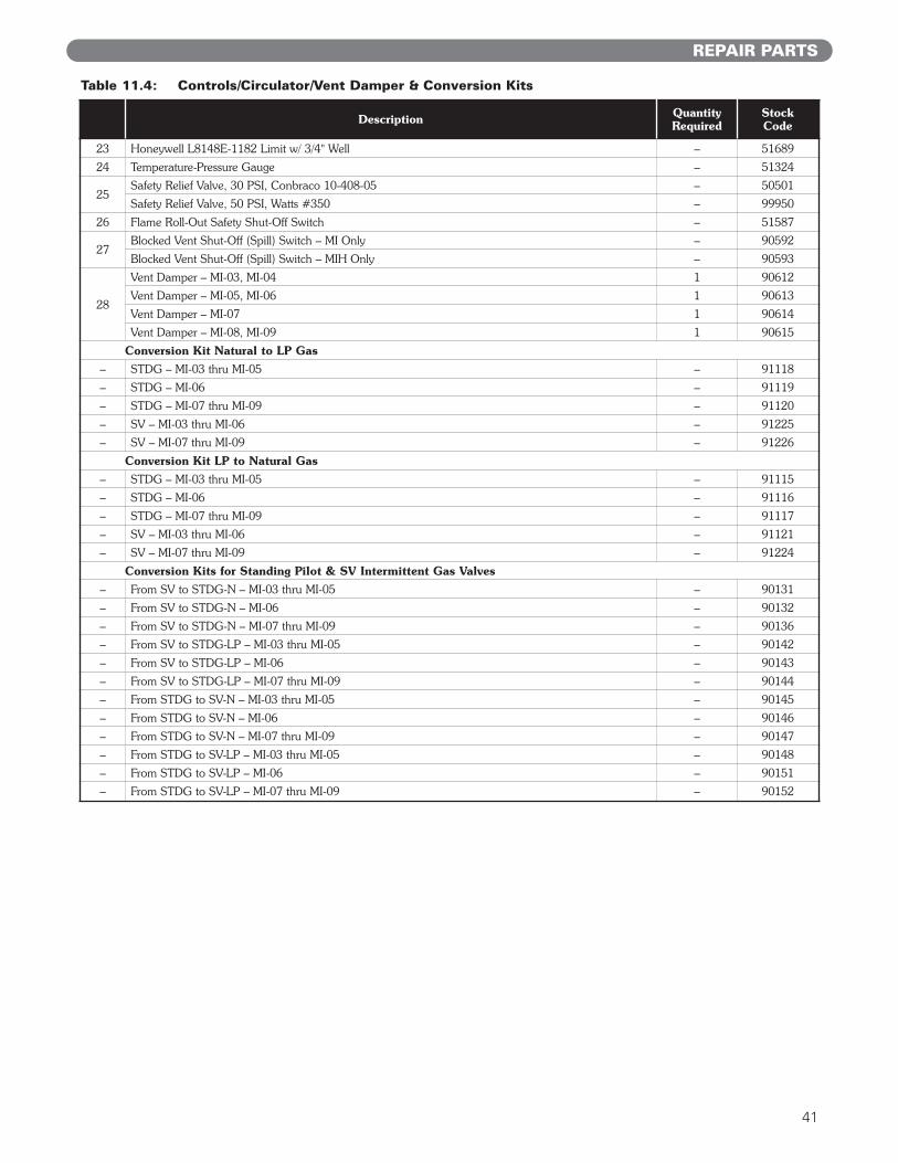
Table 11.4: Controls/Circulator/Vent Damper & Conversion Kits
41
Description QuantityRequired
StockCode
23 Honeywell L8148E-1182 Limit w/ 3/4" Well – 51689
24 Temperature-Pressure Gauge – 51324
25Safety Relief Valve, 30 PSI, Conbraco 10-408-05 – 50501
Safety Relief Valve, 50 PSI, Watts #350 – 99950
26 Flame Roll-Out Safety Shut-Off Switch – 51587
27Blocked Vent Shut-Off (Spill) Switch – MI Only – 90592
Blocked Vent Shut-Off (Spill) Switch – MIH Only – 90593
28
Vent Damper – MI-03, MI-04 1 90612
Vent Damper – MI-05, MI-06 1 90613
Vent Damper – MI-07 1 90614
Vent Damper – MI-08, MI-09 1 90615
Conversion Kit Natural to LP Gas
– STDG – MI-03 thru MI-05 – 91118
– STDG – MI-06 – 91119
– STDG – MI-07 thru MI-09 – 91120
– SV – MI-03 thru MI-06 – 91225
– SV – MI-07 thru MI-09 – 91226
Conversion Kit LP to Natural Gas
– STDG – MI-03 thru MI-05 – 91115
– STDG – MI-06 – 91116
– STDG – MI-07 thru MI-09 – 91117
– SV – MI-03 thru MI-06 – 91121
– SV – MI-07 thru MI-09 – 91224
Conversion Kits for Standing Pilot & SV Intermittent Gas Valves
– From SV to STDG-N – MI-03 thru MI-05 – 90131
– From SV to STDG-N – MI-06 – 90132
– From SV to STDG-N – MI-07 thru MI-09 – 90136
– From SV to STDG-LP – MI-03 thru MI-05 – 90142
– From SV to STDG-LP – MI-06 – 90143
– From SV to STDG-LP – MI-07 thru MI-09 – 90144
– From STDG to SV-N – MI-03 thru MI-05 – 90145
– From STDG to SV-N – MI-06 – 90146
– From STDG to SV-N – MI-07 thru MI-09 – 90147
– From STDG to SV-LP – MI-03 thru MI-05 – 90148
– From STDG to SV-LP – MI-06 – 90151
– From STDG to SV-LP – MI-07 thru MI-09 – 90152
REPAIR PARTS

MI/MIH™
Boilers
SeriesGas
Installation,Operation &MaintenanceManualTO THE INSTALLER:
This manual is the property of the owner and mustbe affixed near the boiler for future reference.
TO THE OWNER:This boiler should be inspected annually by aQualified Service Agency.
MI8038 R13 (10/11-3M)Printed in U.S.A.©2011 PB Heat, LLC. All rights reserved.
PB HEAT, LLC131 S. CHURCH STREET • BALLY, PA 19503
ASME