MIMAKI ENGINEERING CO., LTD.eng.mimaki.co.jp/archives/034/201301/JV33Series_Operation_D201694... ·...
202
MIMAKI ENGINEERING CO., LTD. URL: http: // www.mimaki. co. jp/ D201694-16
Transcript of MIMAKI ENGINEERING CO., LTD.eng.mimaki.co.jp/archives/034/201301/JV33Series_Operation_D201694... ·...

MIMAKI ENGINEERING CO., LTD.URL: http: // www.mimaki. co. jp/ D201694-16

i
CAUTION ........................................................................viiDISCLAIMER OF WARRANTY ......................................viiRequests ........................................................................viiFCC Statement (USA) ....................................................viiInterference to televisions and radios .............................vii
Foreword ........................................................................viiiOn This Operation manual ............................................ viii
Features .......................................................................... ixSafety Precautions .......................................................... xi
Symbols ...........................................................................xi
CHAPTER 1 Before Use
Moving this machine ............................................... 1-2Where to install this machine ....................................1-2Working environmental temperature .........................1-2Moving this machine .................................................1-3
Names of Parts and Functions ............................... 1-4Front ..........................................................................1-4Rear / Sides ..............................................................1-5Operation Panel ........................................................1-6Heater .......................................................................1-7Media sensor .............................................................1-7Carriage ....................................................................1-8Cutter blade and cutting line .....................................1-8Capping station .........................................................1-9Pinch rollers and Feed rollers ...................................1-9
Connecting cables ................................................ 1-10Connecting USB2.0 interface cable ........................1-10Connecting the power cable ....................................1-11
Inserting ink cartridges ......................................... 1-12Caution in handling of ink cartridges .......................1-13Note on Silver and White ink of ES3 ink .................1-14
Media .................................................................... 1-15Usable sizes of media .............................................1-15Caution in handling of medias .................................1-15
Menu mode .......................................................... 1-16
CHAPTER 2 Basic Operations
User type ................................................................ 2-2Set items registrable to User type .............................2-2Using the registered user type ..................................2-2
TABLE OF CONTENTS

ii
Workflow ................................................................ 2-3Turning the power ON/OFF ................................... 2-4
Turning the power ON .............................................. 2-4Turning the power OFF ............................................ 2-5
Setting medias ....................................................... 2-6Useable medias ........................................................ 2-6Adjusting the head height ......................................... 2-6Setting a roll media ................................................... 2-8Take-up device (Except Type B) ............................ 2-13Setting leaf media ................................................... 2-14Changing the printing origin .................................... 2-16
Preparing Heaters ................................................ 2-18Changing temperature settings of Heater ............... 2-18Confirming the Heater temperature ........................ 2-19
Test printing ......................................................... 2-20Perform test printing with the normal test pattern ... 2-21Perform test printing with the test pattern for checking white ink .................................................. 2-22Check warning of white nozzle status (Only when using SS21 white ink) .......................... 2-23
Head Cleaning ..................................................... 2-24About head cleaning ............................................... 2-24Perform head cleaning depending on the test printing result .......................................................... 2-25Perform spot color maintenance ............................. 2-25
Drawing data ........................................................ 2-30Starting the print ..................................................... 2-30Stopping the print temporarily ................................. 2-31Erasing the received data (Data clear) ................... 2-31Cutting a media ...................................................... 2-32
CHAPTER 3 Convenient use
User type ................................................................ 3-2Registering the drawing conditions together (Type registration) .................................................... 3-2Registering Type ...................................................... 3-2
Setting media compensation .................................. 3-5Setting media compensation .................................... 3-5

iii
Changing the set value of Heater ........................... 3-8Changing temperature settings of Heater .................3-8Adjusting suitable temperature adjustment (When solvent ink is used) ......................................3-10In case the heater temperature is too low ...............3-11
Setting print mode ................................................ 3-12Setting of the print quality ........................................3-12Setting scanning direction .......................................3-14Setting Logical-seek ................................................3-15Setting WhiteLay Print .............................................3-16
Setting drying time ................................................ 3-18Setting margins ..................................................... 3-19Setting Priority ...................................................... 3-20Setting Auto cleaning ........................................... 3-22Setting cleaning while printing .............................. 3-24Setting media detection ........................................ 3-26Other settings ....................................................... 3-28Initializing the settings .......................................... 3-30Machine settings ................................................... 3-31
Setting the deodorize fan ........................................3-32Setting Dryness feeding ..........................................3-33Setting Stamp ..........................................................3-34Setting Test draw arrange .......................................3-36Change the operation condition of the room temperature .............................................................3-38Setting confirmation feeding ....................................3-39Setting time .............................................................3-40Setting Unit ..............................................................3-41Setting Machine name ............................................3-42Setting Key buzzer ..................................................3-43
Extension of Ink Expiry Month .............................. 3-44Extension of Ink Expiry Month .................................3-44
Switch Setting of Ink Supply Path ......................... 3-46Confirming machine information ........................... 3-48
Displaying Information .............................................3-48
CHAPTER 4 Routine Maintenance
Maintaining ............................................................. 4-2Precautions in cleaning .............................................4-2Notes on cleaning solution ........................................4-2

iv
Cleaning exterior surfaces ........................................ 4-3Cleaning the platen ................................................... 4-3Cleaning the media sensor ....................................... 4-4Cleaning the media press ......................................... 4-4
Maintaining Capping station ................................... 4-5Cleaning the wiper and ink caps ............................... 4-5Replacing the wiper .................................................. 4-7Prior to Pump tube washing ..................................... 4-8Washing of Head nozzle ......................................... 4-10Cleaning the ink discharge passage (PUMP TUBE WASH) ............................................ 4-12When not using for a long term (CUSTODY WASH) ................................................ 4-14
Cleaning heads and surroundings parts .............. 4-16When Nozzle clogged after cleaning ................... 4-18
Filling up ink ............................................................ 4-18DISCHARGE & WASH ........................................... 4-19Initial ink fill up ........................................................ 4-21
If the Positions of Dots Shift... .............................. 4-23Preventing nozzle clogging while power-off ......... 4-25
Setting refreshing interval in Sleep mode ............... 4-25Setting tube washing interval in Sleep mode .......... 4-26Setting cleaning interval in Sleep mode ................. 4-27
Setting Routine operations ................................... 4-28Setting Routine wiping operations in Standby mode ........................................................ 4-28Setting Refreshing interval in Standby mode ......... 4-30Setting Pump tube washing interval in Standby mode ........................................................ 4-31Setting Cleaning interval in Standby mode ............. 4-32
Other maintenance functions ............................... 4-34Changing the warning time of wiper replacement .. 4-34Setting the media remaining display ....................... 4-35White Ink Maintenance Function ............................ 4-37To use sublimation transfer ink with more stable quality ..................................................................... 4-39If Waste ink tank confirming message is displayed ................................................................ 4-42Changing the ink ..................................................... 4-46
Replacing the cutter blade ................................... 4-47

v
CHAPTER 5 Troubleshooting
Troubleshooting ...................................................... 5-2Power does not turn on .............................................5-2The machine does not start printing ..........................5-2Media get jammed / media is soiled ..........................5-3[HEAT] or [CONSTANT] LED does not light up ........5-3Image quality is poor .................................................5-4Nozzle is clogged ......................................................5-4Ink cartridge warning appears ...................................5-5
Warning / Error Messages ...................................... 5-6Warning messages ...................................................5-6Error messages .........................................................5-9
CHAPTER 6 Appendix
Machine specifications ........................................... 6-2Ink specifications .................................................... 6-4Sheet for inquiry ..................................................... 6-5Warning labels ........................................................ 6-6Function Flowchart ................................................. 6-8

vi

vii
CAUTIONDISCLAIMER OF WARRANTY
THIS LIMITED WARRANTY OF MIMAKI SHALL BE THE SOLE AND EXCLUSIVE WARRANTY AND IS INLIEU OF ALL OTHER WARRANTIES, EXPRESS OR IMPLIED, INCLUDING, BUT NOT LIMITED TO, ANYIMPLIED WARRANTY OF MERCHANTABILITY OR FITNESS, AND MIMAKI NEITHER ASSUMES NORAUTHORIZES DEALER TO ASSUME FOR IT ANY OTHER OBLIGATION OR LIABILITY OR MAKE ANYOTHER WARRANTY OR MAKE ANY OTHER WARRANTY IN CONNECTION WITH ANY PRODUCTWITHOUT MIMAKI’S PRIOR WRITTEN CONSENT.IN NO EVENT SHALL MIMAKI BE LIABLE FOR SPECIAL, INCIDENTAL OR CONSEQUENTIALDAMAGES OR FOR LOSS OF PROFITS OF DEALER OR CUSTOMERS OF ANY PRODUCT.
Requests
• This Operation manual has been carefully prepared for your easy understanding.However, please do not hesitate to contact a distributor in your district or our office if you have anyinquiry.
• Description contained in this Operation manual are subject to change without notice for improvement.
FCC Statement (USA)
This equipment has been tested and found to comply with the limits for a Class A digital device, pursuant toPart 15 of the FCC Rules. These limits are designed to provide reasonable protection against harmfulinterference when the equipment is operated in a commercial environment. This equipment generates,uses and can radiate radio frequency energy and, if not installed and used in accordance with the Operationmanual, may cause harmful interference to radio communications.Operation of this equipment in a residential area is likely to cause harmful interference in which case theuser will be required to correct the interference at his own expense.In the case where MIMAKI-recommended cable is not used for connection of this device, limits provided byFCC rules can be exceeded.To prevent this, use of MIMAKI-recommended cable is essential for the connection of this printer.
Interference to televisions and radios
The product described in this manual generates high frequency when operating.The product can interfere with radios and televisions if set up or commissioned under improper conditions.The product is not guaranteed against any damage to specific-purpose radio and televisions.The product’s interference with your radio or television will be checked by turning on/off the power switch ofthe product.In the event that the product is the cause of interference, try to eliminate it by taking one of the followingcorrective measures or taking some of them in combination.
• Change the orientation of the antenna of the television set or radio to find a position without receptiondifficulty.
• Separate the television set or radio from this product.• Plug the power cord of this product into an outlet which is isolated from power circuits connected to the
television set or radio.

viii
ForewordCongratulations on your purchase of MIMAKI color ink jet printer "JV33-130/160" .
The JV33-130/160 is a color ink-jet printer for high quality printing with solvent ink (4-color/6-color and 8-color) or aqueous ink (4-color and 6-color).
• 4-colors version : 2 each of Cyan, Magenta, Yellow and Black color ink cartridge are usable.• 6-colors version : 1 each of Cyan, Magenta, Yellow, Black, Light cyan and Light magenta
color ink cartridge (2 each of Cyan and Magenta only) are usable.• 6-colors + White version : 1 each of Cyan, Magenta, Yellow, Black, Light cyan, Light magenta and
White color ink cartridge (2 each of White only) are usable.• 7-colors version : 1 each of Cyan, Magenta, Yellow, Black, Light cyan, Light magenta and
Light black color ink cartridge (2 each of Light black only) are usable.• 8-colors version : 1 each of Cyan, Magenta, Yellow, Black, Light cyan, Light magenta, White
and Silver color ink cartridge are usable (available for the firmware V andlater).
JV33-130/160 has a high-end model (Type A) with a take-up device as a standard and a low-price model(Type B) without a take-up device.
On This Operation manual
• This Operation manual is describing the operations and maintenance of "Color inkjet printer JV33-130/160" (called as this machine hereafter)
• Read this Operation manual carefully and understand them thoroughly to use.• It is also necessary to keep this Operation manual on hand.• This Operation manual has been carefully prepared for your easy understanding, however, please do
not hesitate to contact a distributor in your district or our office if you have any inquiry.• Descriptions contained in this Operation manual are subject to change without any notice for
improvement.• In the case when this Operation manual should be illegible due to destruction or lost by fire or
breakage, purchase another copy of the Operation manual from our office.
Reproduction of this manual is strictly prohibited.All Rights Reserved.Copyright
© 2012 MIMAKI ENGINEERING Co., Ltd.

ix
FeaturesThe features of the machine are described below.Understanding them together with the operating instructions given in this manual will help you use themachine properly.
High image quality and High-speed printing realized by the new generation printer head.
Newly developed printer head, 1 head consisting of 1440 nozzles (180 nozzles x 8 lines), is adopted.High image quality and High-speed printing is enabled by adopting the variable dots technology.
Double cartridge automatic change function (In case of the 4-colors mode)
Long-run printing is enabled by the ink capacity of 880 cc /1 color by adopting the ink cartridge (2 car-tridges /1 set) automatic change function.
ES3 ink of the ecological design friendly to human and SS21 suitable for outdoor signs are prepared. (In case of solvent ink used)
ES3 ink requires no special deodorizing equipment and has almost no irritating odor peculiar to a sol-vent, so that this ink is made by the ecological design friendly to human and environment, and suitablefor a designer and operator who cares about odor.SS21 is suitable for outdoor signs and superior to water resistance and weather resistance. No specialhandling nor license is required since an organic rule is not applied to this ink.
Sublimation dye ink and aqueous color pigment ink enabling High image quality and High-speed printing are usable.
• Sublimation dye ink is used when drawn images are transferred to other medias.• aqueous color pigment ink (Pig) is superior to light resistance and suitable for outdoor prints such as
large-sized sign displays. (Signboards)• Aqueous pigment ink (Eco-PA1) is superior to water resistance, not reflected diffusely, better coloring
and color reproducibility than dye ink.
Indication of the ink Remains
Since the amount of ink that remains can be checked even during operation of the machine, you canuse the ink and media without waste.
Intelligent heater equipped
Heaters are arranged at 3 locations of the Pre-heater, Print heater and Post-heater and the tempera-ture of each heater is independently adjustable.Heating temperature is also adjustable to the temperature suitable for the media used since the intelli-gent function consisting of Standby mode and Auto shut-off is provided so that the temperature is con-trolled detecting the environmental temperature.

x
Features
Easy maintenance
The automatic capping system for the heads eliminates the need of head cleaning before turning offthe power. Ink discharge passage is automatically cleaned from the cap.Nozzles can be unclogged by performing the cleaning function.If the machine is not in use for a prolonged period of time, it automatically performs nozzle cloggingpreventive operation at fixed intervals. However, the main power must be left turned on.The machine counts the time when not in use. When the power is turned on or when printing is started,the machine automatically performs head cleaning to prevent nozzle clogging.
Convenient direct keys
Use of the direct keys permits quick access to the respective various built-in functions.
Set of the drawing origin by LED pointer
For easy setting of the drawing origin changed, positioning can be done by a light point of the LEDpointer equipped on the carriage.
Printing information can be checked
The print length can be displayed on the LCD panel during printing and the information of printing con-ditions can be checked by printing it.
High-speed interface
The "USB 2.0" interface allows for high-speed data reception from the computer.
Take-up Device permits printing over a long length (Except Type B)
Even a long sheet of media can be used, since the take-up device interlocked with the machine windsup the printed part of the sheet during printing.
A media support bar newly provided
The machine is provided with a media support bar at the back. It is useful when a heavy roll of media,such as Tarpaulin, is set on the machine.
Adjustable to the height of Head (2 levels)
The height of Head is adjustable in 2mm/3mm by the adjusting lever.
Lifting of the media at its both ends is prevented
The use of the media press prevents the wide sheet of media from lifting at its both ends and coming incontact with the head unit.
xi
Safety PrecautionsSymbols
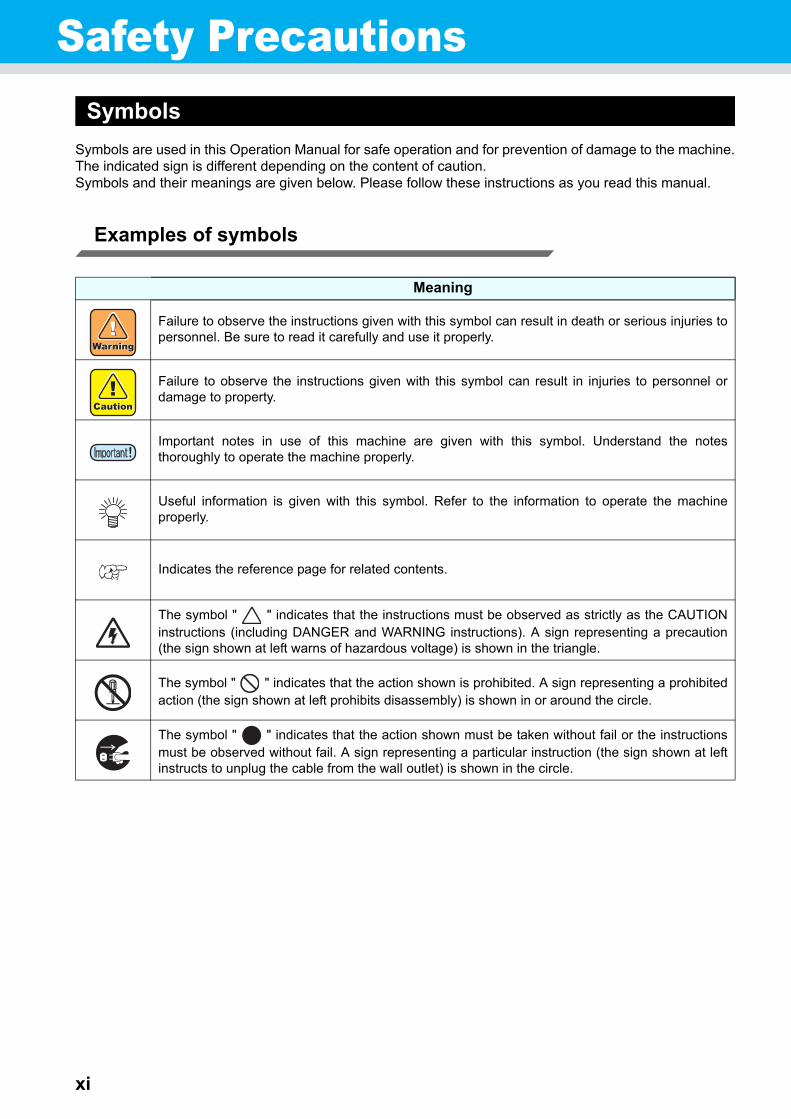
Symbols are used in this Operation Manual for safe operation and for prevention of damage to the machine.The indicated sign is different depending on the content of caution.Symbols and their meanings are given below. Please follow these instructions as you read this manual.
Examples of symbols
Meaning
Failure to observe the instructions given with this symbol can result in death or serious injuries topersonnel. Be sure to read it carefully and use it properly.
Failure to observe the instructions given with this symbol can result in injuries to personnel ordamage to property.
Important notes in use of this machine are given with this symbol. Understand the notesthoroughly to operate the machine properly.
Useful information is given with this symbol. Refer to the information to operate the machineproperly.
Indicates the reference page for related contents.
The symbol " " indicates that the instructions must be observed as strictly as the CAUTIONinstructions (including DANGER and WARNING instructions). A sign representing a precaution(the sign shown at left warns of hazardous voltage) is shown in the triangle.
The symbol " " indicates that the action shown is prohibited. A sign representing a prohibitedaction (the sign shown at left prohibits disassembly) is shown in or around the circle.
The symbol " " indicates that the action shown must be taken without fail or the instructionsmust be observed without fail. A sign representing a particular instruction (the sign shown at leftinstructs to unplug the cable from the wall outlet) is shown in the circle.

xii
Safety Precautions
Warning for Use
WARNING
• Do not use the machine in a poorly ventilated room or a closed room.• Be sure to use the optional Drying ventilation unit when the machine is used in a poorly ventilated
room or a closed room.• Use the attached power cable.• Take care not to damage, break or work upon the power cable. If a heavy material is placed on the
power cable, or if it is heated or pulled, the power cable can break, thus resulting in fire or electricshocks.
• Avoid locating the machine in a damp environment. Do not splash water onto the machine. Use insuch an environment can give rise to fire, electric shocks or breakdown of the machine.
• Use of the machine under an abnormal condition where it produces smoke or strange smell canresult in fire or electric shocks. If such an abnormality is found, be sure to turn off the power switchimmediately and unplug the cable from the wall outlet. Check first that the machine no longerproduces smoke, and then contact your distributor or a sales office of MIMAKI for repair.
• Never repair your machine by yourself since it is very dangerous for you to do so.• Never disassemble or remodel the main unit of the machine or the ink cartridge. Disassembly or
remodeling can result in an electric shock or breakdown of the machine.• Take care that no dust or dirt sticks to platen heaters. Dust and dirt sticking heaters can cause fire.
• The ink used for this machine contains organic solvent. Since the ink is flammable, never use flamein or around the place where this machine is used.
• Hazardous Moving PartsKeep Fingers and Other Body Parts Away

xiii
Precautions in Use
CAUTIONPower supply Handling of ink
• Leave the breaker turned ON.• Do not turn off the main power switch on
the right side of this machine.
• If you get ink in your eyes, immediatelywash your eyes with a lot of clean water forat least 15 minutes. In doing so, also washeyes to rinse ink away completely. Then,consult a doctor as soon as possible.
• If anyone drinks ink by mistake, keep himor her quiet and see a doctor immediately.Do not allow him or her to swallow thevomit. After that, contact the Poison ControlCenter.
• If you inhale a lot of vapor and feel bad,immediately move to a location of fresh airand then keep yourself warm and quiet.Then, consult a doctor as soon as possible.
• The ink contains organic solvent. If inksettles on the skin or clothes, immediatelywash it off with detergent and water.(onlywhen solvent is used)
Heater
• Do not spill liquid on the platen as this maycause failure of the heater or firing.
• Do not touch platen heaters with bare handwhile it is hot; otherwise, you can getburned.
• When the machine is to be moved, waituntil the heater temperature dropsadequately.As a criterion, wait at least 30 minutes afteryou turn off the power to the heater.Moving the machine must be limited to onthe same floor where there is no steps.When the machine is to be moved to anyplace other than on the same step-freefloor, contact your distributor or a salesoffice of MIMAKI.
Note on maintenance
• When cleaning the ink-station or the heads, make sure to wear the attached gloves.Further, when the solvent ink is used, it is necessary to wear the attached goggles.

xiv
Safety Precautions
CAUTIONS and NOTES
WarningHandling of ink cartridges Front cover and lever
• Use the JV33 genuine ink. Remember that the usershall be filled for a repair to correct any damageresulting from the use of ink other than theexclusive type.
• The machine does not operate with any ink otherthan the JV33 genuine ink.
• Do not use the JV33 genuine ink with other printers,as doing so may cause damage to such machines.
• Never refill the ink cartridge with ink. Refilled inkcartridge can cause a trouble. Remember thatMIMAKI assumes no responsibility for any damagecaused by the use of the ink cartridge replenishedwith ink.
• If the ink cartridge is moved from a cold place to awarm place, leave it in the room temperature forthree hours or more before using it.
• Open the ink cartridge just before installing it in themachine. If it is opened and left for an extendedperiod of time, normal printing performance of themachine may not be ensured.
• Make sure to store ink cartridges in a cool and darkplace.
• Store ink cartridges and waste ink tank in a placethat is out of the reach of children.
• Be sure to thoroughly consume the ink in the inkcartridge, once it is opened, within three months. Ifan extended period of time has passed away afteropening the cartridge tank, printing quality would bepoor.
• Neither pound the ink cartridge nor shake itviolently, as doing so can cause leakage of ink.
• Do not touch or stain the contacts of the inkcartridge, as doing so may cause damage to theprint circuit board.
• Waste ink is equivalent to waste oil of industrialwaste. Request an industrial waste disposalcompany for disposal of waste ink.
• Never open the front cover or raise the lever duringprinting. Opening the cover or raising the lever willabort printing.
Handling of media
• Use media recommended by MIMAKI to ensurereliable, high-quality printing.
• Set the heater temperature to meet thecharacteristics of the media.Set the temperature of the Pre-heater, Print heaterand Post-heater according to the type andcharacteristics of the media used. Automatictemperature setting can be made on the operationpanel by setting the profile on the dedicated RIP.For setting on the RIP, refer to the instructionmanual for your RIP.
• Pay attention to the expansion and contraction ofthe media.Do not use media immediately after unpacking. Themedia can be affected by the room temperature andhumidity, and thus it may expand and contract.Themedia have to be left in the atmosphere in whichthey are to be used for 30 minutes or more afterunpacked.
• Do not use curled media.The use of curled media can not only cause amedia jam but also affect print quality.Straighten the sheet of media, if significantly curled,before using it for printing. If a regular-sized coatedsheet of media is rolled and stored, the coated sidehas to face outside.
Protection of media from dust
• Store media in a bag. Wiping off dust accumulatedon media will adversely affect the media due tostatic electricity.
• When leaving the workshop after the working hours,do not leave any media on the roll hanger. If anymedia is left on the roll hanger, it can get dusty.

xv
Safety Precautions
Cautions on Installation
WarningNotes on maintenance
• It is strongly recommended to use the machine in a room that is not dusty. Set the Refresh level 2 or 3 whenthe machine is to be used in an unfavorable environment. (P.3-29 "Setting of Refreshing")
• Keep the front cover closed even when the machine is not printing. If not, dust can accumulate on thenozzles in the heads.
• Dust in the heads can also cause drops of ink to fall suddenly down on the media during printing. In such acase, be sure to clean up the heads. (P.3-22 "Setting Auto cleaning")
• When cleaning the ink-station or the heads, make sure to wear the attached gloves. Further, when thesolvent ink is used, it is necessary to wear the attached goggles.
• Perform wiping (removal of dust and paper powder) of the capping station and wiper frequently.
Periodic replacement parts
• Some parts of this machine must be replaced with a new one periodically by service personnel. Be sure tomake a contract with your distributor or dealer for After sale service to ensure a long life of your machine.
CAUTIONA place exposed to direct sunlight
On an inclined surface A place where temperature or humidity varies significantly
• Use the machine under the following environmental conditions:
• Operating environment:20 to 35 °C (68 to 95 °F)35 to 65 % (Rh)
A place that vibrates A place exposed to direct air flow from an air conditioner or the like.
Around a place where fire is used

This chapter describes the items required to understand beforeuse, such as name of each part of the machine or the installationprocedures.
Moving this machine ..................... 1-2Where to install this machine ............ 1-2Working environmental temperature . 1-2Moving this machine ......................... 1-3
Names of Parts and Functions ..... 1-4Front .................................................. 1-4Rear / Sides ...................................... 1-5Operation Panel ................................ 1-6Heater ............................................... 1-7Media sensor ..................................... 1-7Carriage ............................................ 1-8Cutter blade and cutting line ............. 1-8Capping station ................................. 1-9Pinch rollers and Feed rollers ........... 1-9
Connecting cables ....................... 1-10Connecting USB2.0 interface cable ............................................... 1-10Connecting the power cable ........... 1-11
Inserting ink cartridges ............... 1-12Caution in handling of ink cartridges ........................................ 1-13Note on Silver and White ink of ES3 ink ........................................... 1-14
Media............................................. 1-15Usable sizes of media ..................... 1-15Caution in handling of medias ........ 1-15
Menu mode ................................... 1-16
CHAPTER 1
Before Use

1-2
Moving this machineWhere to install this machine
Secure a suitable installation space before assembling this machine.The place of installation must have enough space for not only this machine itself but also for printing opera-tion.
Working environmental temperature
Use this machine in an environment of 20 to 35°C to ensure reliable printing.Depending on the ambient temperature, the heater temperature may not rise to the set value.
Model Width Depth Height Gross weight
JV33-130 2289mm 739mm 1424mm 145kg
JV33-160 2538mm 739mm 1424mm 160kg
JV33-130 : 3289 mmJV33-160 : 3538 mm
500 mmor more
500 mmor more
1000 mm or more
1000 mm or more
2740 mmor more
Moving this machine
1-3
1
Befo
re Use
Moving this machine
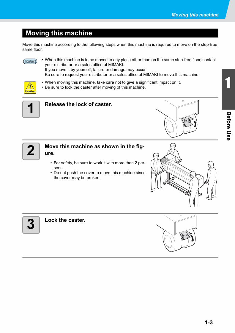
Move this machine according to the following steps when this machine is required to move on the step-free same floor.
1 Release the lock of caster.
2 Move this machine as shown in the fig-ure.
• For safety, be sure to work it with more than 2 per-sons.
• Do not push the cover to move this machine sincethe cover may be broken.
3 Lock the caster.
• When this machine is to be moved to any place other than on the same step-free floor, contact your distributor or a sales office of MIMAKI. If you move it by yourself, failure or damage may occur. Be sure to request your distributor or a sales office of MIMAKI to move this machine.
• When moving this machine, take care not to give a significant impact on it.• Be sure to lock the caster after moving of this machine.

1-4
Names of Parts and FunctionsFront
Front cover
Open the cover in setting of medias, taking of measuresagainst jamming of medias or in maintenance inside thestation. Even when the power switch is off, keep this cover andthe other covers closed.
Carriage
Moves the print head unit from side to side.
Operation panel
This panel has the operation keys required foroperating the machine and the LCDs for displayingsetting items, etc.
Clamp lever (front)
Moves the pinch rollers up and down to hold orrelease the media.
Power switch*1
Turns on/off the power to the machine.
Waste ink tank
Waste ink gathers in this tank.
Stand
Supports the main body of the machine. It is pro-vided with casters that are used to move thismachine.
Take-up device (Except Type B)
Automatically winds up the roll mediaprinted.
Maintenance cover
Open the cover in maintenance.Even when the power switch is off, keepall covers closed.
PlatenThe printed media is sent out, sliding on the platen.Three heaters are installed inside the platen.
Print heater/ Post-heaterFixes and dries the ink on the currently producedprint. (Located inside the platen)
Ink cartridgesEach cartridge contains an ink of aparticular color.
Cartridge protection coverThis prevents an injury or breakage of the machine due to a protrusion of the 440 cc cartridge.(It is located under the ink cartridge.)
*1: The power switch under the operation panel lights in green when the power is turned on, and blinks when thepower switch is turned off. The ink clogging prevention function is periodically operated even when the powerswitch is OFF if the main power switch keeps being ON. (Sleep function) P.1-5

1-5
Names of Parts and Functions
1
Befo
re Use
Rear / Sides
Pre-heater
Preheats the media before printing.(Located inside the platen)
Roll holders
Hold a media by inserting it into the right and left endsof the core of the roll media. Roll holders are availablefor the 2 inches and 3 inches core of the roll media.
AC inlet
Connect the power cable to the AC inlet.
Clamp lever (rear)
Interlocks with the clamp lever inthe font of this machine.
USB 2.0 connector
This is USB2.0 interface connector.
Main power switch
Turns on/off the main power for this machine. Leavethe main power turned on to prevent ink clogging.
Cleaning solution cartridge
Set a dedicated Washings cartridge (optional).

1-6
Operation Panel
Use the operation panel to make settings for printing or operate this machine.
Functions of the JOG keys
Each of the JOG keys varies in function according to the condition of the machine under which the key is used. The functions of the JOG keys are as follows:
Before the detec-tion of media
After the detection of media
When selecting a function
When selecting a setting value
Detects the width of the media.
Shifts the carriage to the left.
Detects the width and length of the media.
Shifts the carriage to the right.
Moves the media inward.
Returns to the previ-ously indicated func-
tion again.
Selects the previously indicated value again.
Moves the media frontward.
Goes to the next func-tion.
Selects the next value.
JOG key
Use these keys to shift the carriage or themedia in [LOCAL mode]. Also use them toselect an item of printing conditions.
keyUse this key to display function setting menu.
keyCancels the last input value or returns the settingmenu to the immediate higher level of the hierar-chy.
Display
Displays the status of the machine, set items and errors.
ACTIVE lamp
Blinks in receiving or drawing data.
keyUse this key to switch between [REMOTE mode]and [LOCAL mode].
keyRegisters the last input value as the setting valueor goes to the immediate lower level of the hierar-chy.
keyUse this key on Station maintenance.
keyDraws test patterns to check if there are anydrawing failures such as ink clogging.
keyUse this key to set the temperatures of thePre-heater, Print heater and Post-heater orcheck the current temperature of the platen.
keySelects User type.
keyExecutes Head cleaning atink clogging.
keyDeletes the data that havebeen received.
CONSTANT lampLights in green when the heater temperaturereaches the set temperature.
HEAT lampLights in orange during heating up of theheater.

1-7
Names of Parts and Functions
1
Befo
re Use
Heater
Pre-heater /Print heater / Post-heater are equipped on the platen.The Pre-heater is used for pre-heating of the media prior to printing to prevent rapid temperature changing.The Print-heater improves the image quality in printing. The Post-heater dries ink after printing.
Media sensor
The media sensor detects the presence of the media and the media length.This machine has a media sensor on the platen (in the rear).
• While the heater is on, the platen is very hot. When the front cover is to be opened or media is to be replaced, lower the heater temperatures and wait until the platen temperature drops; oth-erwise, you can get burned.
• When the media is to be replaced with a thin one, lower the heater temperatures and wait until the platen temperature drops adequately. Setting a thin sheet of media while the platen is hot may cause the media to stick to the platen or cause wrinkling or curling of the media.
• Set the media so that the media sensor located in the rear of the platen is covered with the media without fail. The media can not be detected unless it is placed over the sensor.
Post-heater Print heater Pre-heter
Media sensor

1-8
Carriage
The carriage is provided with the ink heads for printing, the cutter unit for cutting off the sheet of media, etc.A lever is also provided to adjust the height of Head in 2 stages according to the thickness of media. ( P.2-6)
Cutter blade and cutting line
The carriage is provided with a cutter unit for cutting off the media that has been printed on.The cutter cuts off the sheet of media along the cutting line on the platen.
Cutter unit Cutting line
Cutter blade

Names of Parts and Functions
1-9
1
Befo
re Use
Capping station
The capping station consists of the ink caps, the wiper for clean-ing the heads, etc.The ink caps prevent the nozzles in the ink heads from drying up.The wiper cleans the nozzles in the heads.The wiper is consum-able. If the wiper is deformed or the media is stained, replace the wiper with a new one.
Pinch rollers and Feed rollers
This machine retains the media with the pinch rollers and feed rollers. During printing operation, the feed rollers feed the media forward.
• Be sure to wear the attached goggles in cleaning within the capping station to protect your eyes against ink.
• Keep the pinch rollers lifted up when this machine is not in use.If the pinch rollers are left lowered for an extended period of time, they can be deformed and fail to securely retain the media.
Feed roller
Pinch roller

1-10
Connecting cablesConnecting USB2.0 interface cable
Connect the PC and this machine with the USB2.0 inter-face cable.
Notes on USB 2.0 Interface
When two or more JV33 machines are connected to one personal computer
When two or more JV33 machines are connected to one personal computer, the personal computer may not recognize all the JV33 machines normally.Reconnect the unrecognized JV33 machine to another USB port, if available, and check to see if it is recog-nized. If the JV33 machine is not recognized by the newly connected USB port, use USB 2.0 repeater cables available on the market.
Notes on peripheral devices in USB high speed mode
When a peripheral device (USB memory or USB HDD) to be operated in USB high speed mode is con-nected to the same personal computer that a JV33 machine is connected to, the USB device may not be recognized.When a JV33 printer is connected to the personal computer to an externally installed USB hard disk drive , the data output speed to the JV33 machine may drop. That can cause the head unit to stop temporarily at the right or left end during printing.
• Your RIP must be compatible with USB 2.0.• Contact a RIP maker near your location or
our office when the USB2.0 interface is not attached to the PC.
• Your RIP must be compatible with USB 2.0.
USB cable
USB 2.0 repeater cable

Connecting cables
1-11
1
Befo
re Use
Removing USB memory
If a USB memory module is inserted in the personal computer to which a JV33 machine is connected, click "Stop" in the "Safely Remove Hardware" window by following the instructions given there first and then remove the module. Leaving a USB memory module inserted can cause [ERROR 10 COMMAND ERROR].Copy the data onto the hard disk before outputting it for printing.
Connecting the power cable
1 Insert the power cable into an inlet of the machine.
2 Secure a cable band.
• Secure the cable with the cable band attached tothis machine.
3 Insert the power plug into a plug socket.
• Do not use other power cables than the attached power cable.
• Be sure to connect the power cable to the power plug socket near to this machine, and make sure that the power cable is easily removed.
• Connect the power cable to the grounded plug socket. Otherwise, it may result in fire or an electric shock.
Inlet
Power cable
Cable band
Power plug
Socket

1-12
Inserting ink cartridgesInsert an ink cartridges.
1 Shake the ink cartridge as shown on the right.
2 Insert the ink cartridge.
• Insert the ink cartridge lengthwise directing thesurface having IC chips to the left side.
• Colors are displayed on the display as follows.Black: K, Cyan: C, Magenta: M, Yellow: Y, Light cyan: c, Light magenta: m, White: W, Silver: S, Light black: k
Changing an ink cartridge
Perform as follows when [INK END] or [INK NEAR END] is displayed on the display.
When [INK END] is displayed
(1)Pull out an ink cartridge to be replaced.(2) Insert a new ink cartridge, paying attention to the direction of IC chip.
When [INK NEAR END] is displayed
There is a little of ink left. It is recommended to replace the ink cartridge soon since ink may become empty in printing while printing is continuously enabled.
• During [INK NEAR END] is displayed, the setting of In-printing cleaning is disabled. ( P.3-24)
• If solvent ink is selected when the machine is installed, it is not possible to change from the solvent ink to dye ink or aqueous ink.

1-13
Inserting ink cartridges
1
Befo
re Use
For Ink cartridge lamps
The condition of the ink cartridges set in the machine is confirmable with lamps located over the ink car-tridges.
Caution in handling of ink cartridges
Condition of Lamp Description
Upper rowRed lamp
OFF No error
Blinking
One of the following errors occurs.• Ink near-end• Ink end• Expiration of a term of ink validity(one month)
ON
One of the following errors occurs.• No ink left• No ink cartridge inserted• Other ink errors ( P.5-5)
Lower rowGreen lamp
OFF No error
ON
When used with 4-color ink set, themachine supplies ink from the ink car-tridge with lower ink. In this case, thecartridge being used lights in green.
• An organic solvent is used in solvent ink. When ink sticks on skins, wash it with soapy waterimmediately then rinse it off with water fully. If you get ink in your eyes, immediately wash youreyes with a lot of clean running water for at least 15 minutes. In doing so, also wash the eyessto rinse ink away completely. Then, consult a doctor as soon as possible.
• Use genuine ink cartridges for this machine. This machine functions by recognizing the genu-ine ink cartridges. In case of troubles caused by modified ink cartridges or the like, it shall beout of the warranty even within the warranty period.
• If the ink cartridge is moved from a cold place to a warm place, leave it in the room temperaturefor three hours or more before using it.
• Be sure to thoroughly consume the ink in the ink cartridge, once it is opened, within threemonths. If an extended period of time has passed away after opening the cartridge tank, print-ing quality would be poor.
• Make sure to store ink cartridges in a cool and dark place.• Store ink cartridges and waste ink tank in a place that is out of the reach of children.• Request an industrial waste processor for processing of empty ink cartridges.• Do not shake ink cartridges violently. This may result in ink leakage from the ink cartridges.• Never refill the ink cartridges with ink. This may result in troubles.
MIMAKI will not bear any responsibility for any damage caused by the use of the ink cartridgesrefilled with ink.
• Do not touch or stain the contacts of the ink cartridge. This may cause damages on printed cir-cuit boards.
• Do not disassemble the ink cartridges.
Ink cartridge lamps

Inserting ink cartridges
1-14
Note on Silver and White ink of ES3 ink
Be sure to read below before using silver and white ink of ES3 ink.
Pigments of silver ink and white ink will settle down with time.
Pigments of silver and white ink of ES3 ink have nature of settling down when they are left for a long time.If you print with ink whose pigments settle down as it is, it may cause color heterogeneity etc.
If you have not use ink for a long time, be sure to perform “spot color maintenance” beforeprinting.
When you print with silver ink or white ink that has set on the machine and has not been used for a long time, first perform “spot color maintenance” to prevent color heterogeneity due to settling down of pig-ments. ( P.2-25 "Perform spot color maintenance")
If you have left ink for a long time, the warning message is displayed when you turn on thepower supply.
If you have left ink for a long time, the warning message that informs you that it is required to perform maintenance is displayed when you turn on the power supply.By referring to P.2-28 "About warning message display of performing spot color maintenance", perform maintenance.
• Silver and white ink of ES3 ink are usable for the firmware V and later.
• Do not turn off the main power supply of this machine after you filled silver ink or white ink of ES3 ink. (If you do not use the printer, turn off the power supply with the switch on the front surface of the machine.)

1-15
1
Befo
re Use
MediaUseable media sizes and notes for handling are described.
Usable sizes of media
Caution in handling of medias
Pay attention to the followings for handling of medias.
Model JV33-130 JV33-160
Type of Recommended media Tarpaulin/ FF(Flexible Face)/ Weatherproof PVC
Maximum width 1371mm 1620mm
Minimum width 210mm 210mm
Maximum printing width 1361mm 1610mm
Ro
ll m
edia
Thickness 1.0mm or less
Roll outside diameter 180mm or less
Roll weight 25kg or less
Roll inside diameter 3 or 2 inches
Side printed Side facing outward
Roll end treatmentThe roll end is gently fixed to the core with weak-adhesivetape or weak glue for easy removal.
• Use media recommended by MIMAKI to ensure reliable, high-quality printing.Set the heater temperature to meet the characteristics of the media.
• Set the temperature of the Pre-heater, Print heater and Post-heater according to the type and characteristics of the media used.Automatic temperature setting can be made on the operation panel by setting the profile on the dedicated RIP. For setting on the RIP, refer to the instruction manual for your RIP.
• Pay attention to the expansion and contraction of the media.Do not use media immediately after unpacking. The media can be affected by the room tem-perature and humidity, and thus it may expand and contract.The media have to be left in the atmosphere in which they are to be used for 30 minutes or more after unpacked.
• Do not use curled media.This may result in paper jamming.If a regular-sized coated sheet of media is rolled and stored, the coated side has to face out-side.

1-16
Menu modeThis machine has 4 modes. Each menu mode is described below.
NOT-READY mode
This is the mode in which the media has not been detected yet.The keys other than the key and the / key are effective.
LOCAL mode
Local mode is the mode for the drawing preparation state.All the keys are effective.The machine can receive data from the computer.However, it does not perform printing.
This mode permits the following operations:
• Pressing the JOG keys to set up a drawing origin and drawing area.
• Pressing the key to perform [TEST DRAW].
• Pressing the key to execute the cleaning of the heads.
• Pressing the key to set functions.
• Pressing the key to set the temperature of the heaters.
• Pressing the key to check the remaining amount of ink, the description of the cartridge error,the model name, the firmware version, and so on.
• Pressing the key to switch between [REMOTE mode] and [LOCAL mode].
• Pressing the key to erase the printing data the machine has received.
• Pressing the key to change the user type.
• Pressing the key to activate directly [ST.MAINTENANCE], one of the [MAINTENANCE]functions.
FUNCTION mode
To set FUNCTION mode, press the key when this machine is in LOCAL mode.In this mode, printing conditions can be set.
REMOTE mode
This machine prints the data it receives.During drawing, the drawing is interrupted by pressing the key.
<LOCAL.1> [#01]
width:1000mm
Screen display in Local mode
Displays current user type( P.2-2).
Displays machine name ( P.3-42) to recognize the device.
Displays the detected media width.
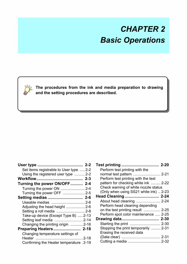
The procedures from the ink and media preparation to drawingand the setting procedures are described.
User type ........................................ 2-2Set items registrable to User type ..... 2-2Using the registered user type .......... 2-2
Workflow......................................... 2-3Turning the power ON/OFF........... 2-4
Turning the power ON ....................... 2-4Turning the power OFF ..................... 2-5
Setting medias ............................... 2-6Useable medias ................................ 2-6Adjusting the head height .................. 2-6Setting a roll media ........................... 2-8Take-up device (Except Type B) ..... 2-13Setting leaf media ........................... 2-14Changing the printing origin ............ 2-16
Preparing Heaters........................ 2-18Changing temperature settings of Heater ............................................. 2-18Confirming the Heater temperature . 2-19
Test printing ................................. 2-20Perform test printing with the normal test pattern .......................... 2-21Perform test printing with the test pattern for checking white ink ......... 2-22Check warning of white nozzle status (Only when using SS21 white ink) .. 2-23
Head Cleaning .............................. 2-24About head cleaning ....................... 2-24Perform head cleaning depending on the test printing result ................ 2-25Perform spot color maintenance ..... 2-25
Drawing data................................. 2-30Starting the print ............................. 2-30Stopping the print temporarily ......... 2-31Erasing the received data (Data clear) ..................................... 2-31Cutting a media ............................... 2-32
CHAPTER 2
Basic Operations

2-2
User typeDrawing of higher quality prints is available by making (setting of User type) the print set matching to the characteristics of media when this machine is used for drawing.On this machine, 4 types of User type 1 to 4 are settable.
Set items registrable to User type
For the registering procedures to User type (1 to 4), refer to P.3-2 .
Using the registered user type
1 In the local mode, press the key.
2 Select User type (1 to 4) by using the keys.
• This is also selectable by pressing the key.
3 Press the key.
For selecting the user type without the key.
The user type is selectable from the local mode by pressing the key, not by pressing the key.
Set items Reference page
Set items Reference page
Setting Media compensation P.3-5 Setting of Refreshing
P.3-28Changing the set value of Heater P.3-8 Setting of Adsorption
Setting Print mode P.3-12 Setting of Feeding speed level
Setting of the number of ink layers P.3-28 Setting of Priority P.3-20
Setting of Drying time P.3-18 Setting of Auto cleaning P.3-22
Setting of Auto cutP.3-28
Setting of In-printing cleaning P.3-24
Setting of Pre-feeding Setting of Media detection P.3-26
Setting of Margins P.3-19 Setting of Feed origin P.3-28
Setting of Color patterns P.3-28
In the local mode, press the
key.
Press the key after [SET UP] is
confirmed.
Select User type (1 to 4) by pressing
the keys.
Press the key.
< L OC A L . 1 > [ # 0 1 ]w i d t h : * * * * mm
USER T YPE CHANGET YPE ( 1 ) - > < 2 > : e n t
< L OC A L . 2 > [ # 0 1 ]w i d t h : * * * * mm
Number of the selected user type

2-3
2
Basic O
peratio
ns
Workflow
1 Turning the power ON/OFF
2
3
Setting medias
4
Preparing Heaters
5
Test printing
Drawing data
Referring to "Turning the power ON/OFF" ( P.2-4).
Referring to "Setting medias" ( P.2-6).
Referring to "Preparing Heaters" ( P.2-18).
Referring to "Test printing" ( P.2-20).
Referring to "Drawing data"( P.2-30).

2-4
Turning the power ON/OFFTurning the power ON
The machine is provided with the following two power switches.Main power switch : At the side of this machine. Keep it "ON" always.Power switch : Normally, use this switch to turn the power ON/OFF. The power switch lights in
green when the power is ON and blinks in green when it is OFF.The power switch under the operation panel lights in green when the power is turned on, and blinks when the power switch is turned off.The nozzle clogging prevention function is periodically operated even when the power switch is OFF if the main power switch keeps being ON. (The power switch blinks in green.)
1 Turn the main power switch ON.
• Set the main power switch located on the side ofthis machine to the "I" side.
• The firmware version is displayed when the poweris turned on.
• This machine performs initial operation.
2 This machine enters the LOCAL mode.
3 Turn the power of the connected PC ON.
• Turn the power ON after the front cover and maintenance cover are closed.• The head nozzle may result in nozzle clogging if the main power switch is kept being "OFF" for
a long time.
Main power switch
J V 3 3 - 1 6 0 V * . * *
P l e a s e Wa i t
< L OC A L . 1 > [ # 0 1 ]

Turning the power ON/OFF
2-5
2
Basic O
peratio
ns
Turning the power OFF
Turn the power OFF by pressing the power switch located on the side of after using.Check the followings when the power is turned off.
• If it is in receiving of data from the PC, or there is any data un-output.• If the head has returned to the capping station.• If any error occurs. ( P.5-9 "Error messages")
1 Turn the power of the connected PC OFF.
2 Turn the power OFF by pressing the power switch.
• The power switch blinks in green.• Do not turn the main power switch located on the
side of this machine.• To use this machine again, light the green lamp by
pressing the power switch.
Cautions in turning the power OFF
Do not turn the main power switch OFF.If the main power switch is ON, the power periodically turns on and the nozzle clogging prevention function(Flushing function) is operated. If the main power switch is OFF, the sleep function such as the flushing function does not work and thismay cause nozzle clogging.
Keep the front cover and the maintenance cover closed.If the cover is opened, the sleep function such as the flushing function does not work.
Turn the power OFF after confirming of the head position.If the power is turned off in such condition that the head does not return to the capping station, this maycause nozzle clogging due to drying of the head.At this case, turn the power ON again, and then turn the power OFF after confirming of that the head hasreturned to the capping station.
Do not turn the power OFF in drawing.The head may not return to the capping station.
Turn the power switch OFF then turn the main power switch OFF.When turning the main power switch off for moving the machine or for solving the error or the like, pressthe power switch on the front of the machine, check the display is turned off on the operation panel, andthen turn the main power switch off.
Power switch

2-6
Setting mediasUseable medias
This machine can be used with roll media and leaf sheet media.For useable medias, refer to P.1-15 "Usable sizes of media".
Adjusting the head height
Adjust the head height according to the thickness of the media used.
Adjusting the head height
1 Move the carriage to the platen.
• When the device is turned on :Execute [ST.MAINTENANCE] - [CARRIAGE OUT]( P.4-5 Step 1,2 )
• When the device is turned off :Open the front cover, then move the carriage withhand.
2 Loosen two screws located at the front.
• Loosen the screws, rotating by one turn with ascrewdriver.
3 Adjust the height-adjusting lever according to the media.
• Adjust the position of the lever, referring to "Forthe adjusting lever and the range".
• Set the height-adjusting lever to the highest stageor the lowest stage. Setting it to the intermediateheight, a printing fault can result.
• Adjust the head height prior to setting of the media. If the head height is adjusted after the media is set, this may cause media jamming, deterioration of the drawing quality or head dam-age.
• The range of the initial head height is adjustable by 2 levels according to the purpose of use.• The range of the printing height of JV33 is from the general printing (L range: 2 mm/3 mm) to
the transfer printing (H range: 4 mm/5 mm) (Set to L range 2 mm at shipping)• If the drawing quality is set to "Bi-D" ( P.3-14) , perform "DROP POSITION" of the mainte-
nance function after the head height is adjusted. ( P.4-23)
Carriage
Screws
Height adjust-ing lever

2-7
Setting medias
2
Basic O
peratio
ns
4 Keeping the height adjusting lever held at the aforementioned position, tighten the two screws.
• Be sure to fasten the screws, pressing the height-adjusting lever, otherwise the head can not besecured at the correct position.
• Fasten the screws securely.
5 Return the carriage to the station posi-tion.
For the adjusting lever and the range
RangeHeight adjusting
leverHead height Switching area
L range (General printing)
Thin : light-weight2mm
(The set position at shipping)
Switch by user
Contact to our sales office for switching
L <-> H by field per-son.
Thick : heavy-weight 3mm
H range(Transfer type
printing)
Thin : light-weight 4mm
Thick : heavy-weight 5mm
• Set the lever to "Thick" when a thicker media such as a tarpaulin or FF is used.• Set the lever to the lower stage (Thick) if dust is likely to gather in the head or the head is likely
to rub on the media to leave ink on it.
• If solvent ink is selected, do not use with H range. It adversely affects the image quality.• When using the media of 1mm thickness or below and SS21 ink, be sure to set the head
height to “Thin”.If using with the head height “Thick”, as the head gap (between the media and the height of head nozzle surface) can be too large and ink drops may be splashed, the image quality can-not be assured.
• When the ink is changed from dye ink to other aqueous ink, or on the contrary, after the machine is installed, the adjustment is required for the head initial height (H/L range). Consult with our sales office about it.

2-8
Setting a roll media
Set a roll media to the roll media hanger located on the back of this machine.
1 Move the roll holder located in the back of the device to the direction of the middle of the device.
• Loosen the roll holder fixing screw and then moveit.
2 Check the clamp lever is lowered.
• Take care not to drop the media on a foot or so when the media is set. It may cause an injury due to the media.
• The roll stopper arm works with the clamp lever. Do not push the clamp lever down while roll stopper is caught between the roll stopper arm and this machine. The roll stopper arm might be broken and roll stopper function *1 might be disabled.
*1. The function that once pulled out a certain amount of media, media pullout is temporarily locked.
OK
NG
Roll stopper arm
Roll holder
Device side
Roll stopper
Roll stopper arm
Roll stopper
Roll holder
Device side
Lock screw
Roll holder

2-9
Setting medias
2
Basic O
peratio
ns
3 Move the roll holder to the roll setting position.
• Check the roll stopper is not caught between the roll stopper arm and this machine.
4 Tighten the roll holder fixing screw.
• Check the Step 2 to 3 again.
5 Set the left end of the core of the roll media on the let roll holder.
• Push the roll media onto the roll holder until theroll core is all the way seated.
6 Loosen the screw of the right side roll holder then insert the holder into the core of the roll media.
7 Raise the clamp lever in the front of this machine.
Rol l HolderSet Posi t ion
3 Inch Rol l Media
2 Inch Rol l Media
Roll holder
Basis
Setting position of 3inch tube
Setting position of 2inch tube
Roll Holder Side (The back of this machine)
Rol l HolderSet Posi t ion
3 Inch Rol l Media
2 Inch Rol l Media
Set the base position of roll holder within this range.
• There are two types of the internal diameter of the roll media paper tube: 2 inch and 3 inch.
Clamp lever
2-10
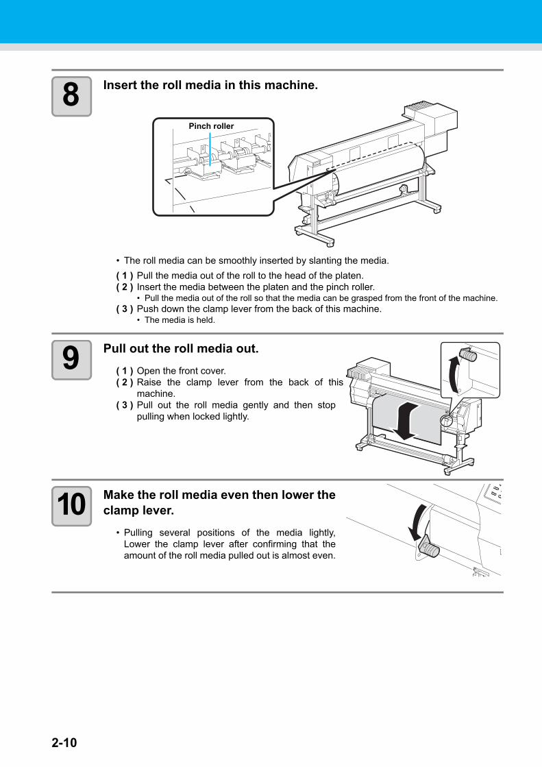
8 Insert the roll media in this machine.
• The roll media can be smoothly inserted by slanting the media.
( 1 ) Pull the media out of the roll to the head of the platen.( 2 ) Insert the media between the platen and the pinch roller.
• Pull the media out of the roll so that the media can be grasped from the front of the machine.( 3 ) Push down the clamp lever from the back of this machine.
• The media is held.
9 Pull out the roll media out.
( 1 ) Open the front cover.( 2 ) Raise the clamp lever from the back of this
machine.( 3 ) Pull out the roll media gently and then stop
pulling when locked lightly.
10 Make the roll media even then lower theclamp lever.
• Pulling several positions of the media lightly,Lower the clamp lever after confirming that theamount of the roll media pulled out is almost even.
Pinch roller

2-11
Setting medias
2
Basic O
peratio
ns
11 Hold the media with the media pressgently.
• Set the media so that no media sticks out from theright end pinch roller to the right side.
• When using a thick media, remove the mediapress from the media before printing.
12 Prepare the take-up device.
• When the Type B is used, the take-up device isnot equipped. Go to the Step 13.
( 1 ) Set an empty core of the roll media on the take-up device.
( 2 ) Close the front cover.
13 Press the key to select “ROLL” .
• Detects the media width.• When [MEDIA RESIDUAL] of the maintenance function is “ON” ( P.4-35), the screen for
entering media remaining amount is displayed after detecting the media width.
• Do not set media at the position which the media press touches the side plate on the right.As media may tilt and be lifted, it could break the head.
• If a media is misaligned to the right more than fixed position, a warning is displayed. Set the media again.
Media press
* * * * * E RROR 5 0 * * * * *ME D I A S E T POS I T I ON R
Media
Media Press
Side plate on the right
Media press position:27 to 38 mm from the side plate on the right.(For the variation of the inside diameter of media roll, it ranges as above.)
• Do not locate the suction hole on the platen between the media and the media press. (It may stain the media.) Suction
hole
Front cover
Core
Take-up device
ME D I A S E L E C TRO L L < > L E A F

2-12
14 Secure the media on the take-updevice. ( P.2-13)
• When the Type B is used, this operation is notneeded.
( 1 ) Feed the media up to the core of the roll mediaof the take-up device by pressing the key.
( 2 ) Fix the middle of the media with adhesive tape.( 3 ) In the same manner, fix the left side and right
side of the media.• Make sure that the there is no slack or wrinkle on
the media in such condition that the roll media ispulled to right and left evenly, and then stick thetape.
Entering the media remaining amount
When [MEDIA RESIDUAL] of the maintenance function is “ON” ( P.4-35), the screen for entering media remaining amount is displayed after detecting the media width.
1 Display the screen for entering media remaining amount.
2 Press and key to enter the media remaining amount.
3 Press the key.
I n p u t o f M e d i a L e n g t hME D I A L E NG T H = x x x . x m
I n p u t o f M e d i a L e n g t hME D I A L E NG T H = 5 0 . 0 m

2-13
Setting medias
2
Basic O
peratio
ns
Take-up device (Except Type B)
The take-up direction of media is selectable by using the switch of the take-up device.
Lever in top position (REVERSE) :The take-up device winds the media with the printed side facing in.
Lever in middle position (OFF) :The take-up device does not wind the media.
Lever in bottom position (FORWARD) :The take-up device winds the media with the printed side facing out.
Setting the torque limiter
The take-up device is provided with a torque limiter.The take-up torque can be adjusted with the torque limiter. (The torque limiter is set at the maximum value when shipped from the factory.)If the tension is too strong to use a thin sheet of media, lower the take-up torque with the torque limiter.
• Clockwise turn : Increases torque (a heavy and thicker media such as tarpaulin or the like)• Counterclockwise turn : Decreases torque (For light media)
• When the torque limiter is adjusted too weak ;The media can not be taken up firmly.
• When the torque limiter is adjusted too strong ;The slack may occur depending on the media and cause influence on the image quality.
50% of maximum torque
100% of the maximum torque value.
Torque indicator
Adjustment nut

2-14
Setting leaf media
Unlike roll media, leaf media does not need to be retained with the roll holders.
1 Open the front cover.
2 Raise the clamp lever.
3 Insert the leaf media between the platen and the pinch rollers.
• Set the media so that no media sticks out from theright end pinch roller to the right side.
4 Hold the media with the media press gently.
• Set the media so that no media sticks out from theright end pinch roller to the right side.
• When using a thick media, remove the mediapress from the media before printing.
5 Push down the clamp lever.
• Set the media straight.
6 Close the front cover.
Front cover
Clamp lever
Pinch roller
Media press

2-15
Setting medias
2
Basic O
peratio
ns
7 Press the key.
8 Press the key to select “LEAF” .
9 The media detection is started.
( 1 ) The media width is detected.( 2 ) The media is fed then the rear end of media is detected.( 3 ) It returns to the local mode when the detection is completed.
Notes when using media press
• Do not set media at the position which the media press touches the side plate on the right.As media may tilt and be lifted, it could break the head.
• If a media is misaligned to the right more than fixed position, a warning is displayed. Set the media again.
ME D I A S E L E C TRO L L < > L E A F
D E T E C T I NG ME D I A NOWP L E A S E WA I T
* * * * * E RROR 5 0 * * * * *ME D I A S E T POS I T I ON R
Media
Media Press
Side plate on the right
Media press position:27 to 38 mm from the side plate on the right.(For the variation of the inside diameter of media roll, it ranges as above.)
• Do not locate the suction hole on the platen between the media and the media press. (It may stain the media.) Suction
hole

2-16
Changing the printing origin
The position of the printing origin can be changed.Moving the LED pointer to the changing position and deciding the position.
1 In the local mode, press the keys.
• It enters into the origin setting mode.
2 Set a light point of the LED pointer to the changing position by pressing the keys.
• Select the carriage and media, moving thepoint with the keys.
3 After determining the origin, press the key.
• The printing origin is changed.
• The origin position set above misaligns with the feeding direction of a media by a few centime-ters. Turn [FEED ORIGIN] “ON” in setup mode to fit the origin to the correct light position of LED pointer. ( P.3-4)
OR I G I N S E T U P0 . 0 - - - -
OR I G I N S E T U P0 . 0 0 . 0
Origin (Length)
Origin (Width)
OR I G I N S E T U P* * OR I G I N * *

Setting medias
2-17
2
Basic O
peratio
ns
Typical setting position of printing origin
The printing origin in the depth direction (X') is positioned at about 40 mm rearward from the cutting line.The printing origin in the scanning direction (Y') is positioned at 15 mm from the right end of the media.The value in the scanning direction (Y') can be changed using [MARGIN] in FUNCTION mode.This can be changed by using the Jog key.
Cutting lineAbout 40 mm
(X')
15 mm (Y')

2-18
Preparing HeatersChanging temperature settings of Heater
The set temperature of Heater can be changed and stored by [HEATER] of the setup mode. ( P.3-8)The adjusting procedures of the temperature set in the setup mode are described below.Set the Heater temperature according to the media used.
• The Heater temperature has been set to "OFF" when purchased.• Proper temperature adjustment is enabled since the temperature is adjustable even in drawing.• It may take several minutes to several ten minutes to reach the set temperature depending on the envi-
ronmental temperature.
1 Press the key.
2 Press the key.
3 Set the temperature of each Heater by pressing the keys.
Heater selecting : Select with the keysTemperature setting : Set with the keys
• Heating of Heater starts. (The [HEAT] lamp lights in orange.)
4 Heater heating ends.
• The [HEAT] lamp goes out then the [CONSTANT] lamp lights in green when the Heatertemperature reaches the set temperature.
5 Press the key to end.
• It returns to the local mode.
• The Heater temperature is registrable beforehand according to the media to be used.P.3-2 "Registering the drawing conditions together (Type registration)"
• The temperature set by the operations above does not reflect the Heater set temperature of the type registration. The set continues until the power is turned off or the temperature is newly set according to the following conditions.(1)Change the type of the setup mode.(2)Change the Heater temperature of the setup mode.(3)Designate the Heater temperature from the PC.
• The Heater temperature is controllable at the RIP side if the RIP in use has a function control-lable. (For the setting procedures, refer to the instruction manual of the RIP in use.)
• Use this machine under 20 to 35°C. The temperature may not reach the set value due to the environmental temperature condition.
P R E P R T POS T3 5 ° C 4 0 ° C 5 0 ° C
Heater temperature confirming display
4 0 ° C 4 0 ° C 5 0 ° C( O F F O F F O F F )
The temperature set in [HEATER] of the type registration.
4 0 ° C 4 0 ° C 5 0 ° C( O F F O F F O F F )
The set temperature : 20 to 50°C
Preparing Heaters
2-19
2
Basic O
peratio
ns
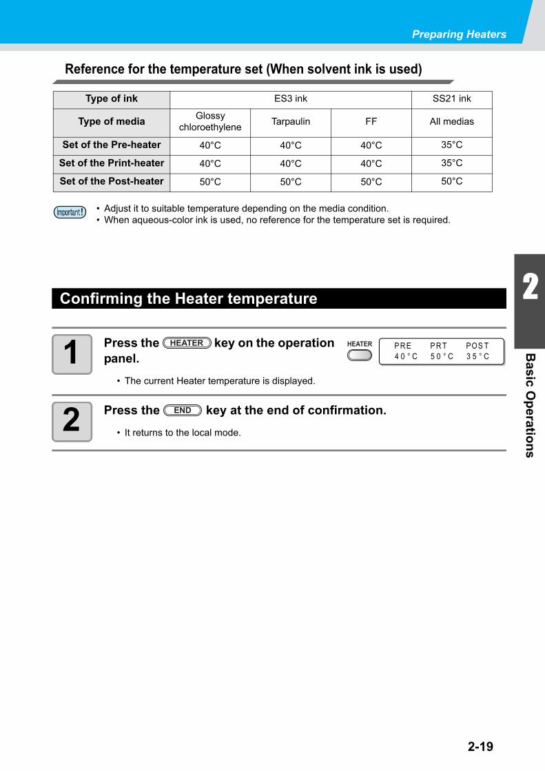
Reference for the temperature set (When solvent ink is used)
Confirming the Heater temperature
1 Press the key on the operation panel.
• The current Heater temperature is displayed.
2 Press the key at the end of confirmation.
• It returns to the local mode.
Type of ink ES3 ink SS21 ink
Type of mediaGlossy
chloroethyleneTarpaulin FF All medias
Set of the Pre-heater 40°C 40°C 40°C 35°C
Set of the Print-heater 40°C 40°C 40°C 35°C
Set of the Post-heater 50°C 50°C 50°C 50°C
• Adjust it to suitable temperature depending on the media condition.• When aqueous-color ink is used, no reference for the temperature set is required.
P R E P R T POS T4 0 ° C 5 0 ° C 3 5 ° C

2-20
Test printingPrint a test pattern to check that there are no discharging defects such as nozzle clogging (slight touching of ink or nozzle missing).
About test patterns
This machine provides you two test patterns.
Normal test pattern (when using ink other than white ink)
When you use ink that you can check by printing a test pattern on a white media, print this test pattern.
Test pattern for checking white ink
When you use a white media and wish to check discharging status of white ink, print this test pattern.
Note on test printing
• When using a leaf medium, set one that is larger than an A4-size medium in the longitudinal direction.
• When using a roll medium, rewind the medium by hand before printing so that it is not loose. When the roll medium has not been rewound tightly, it may cause image quality to deteriorate.

2-21
Test printing
2
Basic O
peratio
ns
Perform test printing with the normal test pattern
1 In the local mode, press the key.
• Press and key to change the test pattern deployment direction. The deployment direction changed here returns to the direction set in P.3-36 after testprinting.
• When performing test printing after changing the deployment direction from “SCAN DIR.”to “FEED DIR.”, the line will be fed to the position of the first test printing.
• For the detail of the deployment direction of the test printing, see P.3-36.
2 Press the key.
• This machine starts printing the test pattern.
• After performing test printing, this machine returnsto LOCAL mode.
3 Check the printed test pattern.
• Finish the operations when it is in normal.• Execute the head cleaning when it is in abnormal. ( P.2-25)
Check before the test printing
• If a media has been set. P.2-6 • If the origin position has been set.
• If the head gap has been adjusted. P.2-6
T E S T DR AW( F E E D D I R . ) < E N T >
* * T E S T DR AW * *
< L OC A L . 1 > [ # 0 1 ]w i d t h : * * * * mm
Abnormal pattern
Clogged with ink
Normal pattern
Nozzles are dirty

2-22
Perform test printing with the test pattern for checking white ink
1 In the local mode, press the key.
2 Press the key to select the “(WHITE CHK.)”.
3 Press the key.
• Print a test pattern in the following orders.• In the second line of the screen, remaining time
from the start of printing is displayed.
(1)Print the pattern daubed with black.(2)Dry the pattern for thirty seconds.(3)Return the media automatically and print the test pattern.
4 Check the printed test pattern.
• Finish the operations when it is in normal.• Execute the head cleaning when it is in abnormal. ( P.2-25)
Check before the test printing
• If a media has been set. P.2-6 • If the origin position has been set.
• If the head gap has been adjusted. P.2-6
T E S T DR AW( F E E D D I R . ) < E N T >
T E S T P R I N T( WH I T E CH K . ) < E N T >
* * T E S T DR AW * *
Abnormal pattern
Clogged with ink
Normal pattern
Nozzles are dirty

Test printing
2-23
2
Basic O
peratio
ns
Check warning of white nozzle status (Only when using SS21 white ink)
As SS21 white ink is easier to cause nozzle clogging compared to other ink, you must keep the nozzle sta-tus normal even when you do not discharge it.In order to keep the nozzle status normal, this machine displays the warn-ing message in the right once a fortnight*1.
The warning message will be displayed after the media detection is performed. When the warning message is displayed, perform the following:
1 When the warning message is dis-played, press the key.
• The machine enters into the waiting for test printing status.
2 Press the key to select the type of the test printing.
3 Press the key.
• Print the test pattern.
*1. A fortnight after clearance of the warning message or maintenance of the white ink.
• After the warning message is displayed, when you perform "Perform test printing with the test pattern for checking white ink"( the previous page) or "White Ink Maintenance Func-tion"( P.4-37), the warning will be released.
• When the warning message is displayed, you can cancel it by pressing the key. How-ever, after the next media detection is performed, the warning message will be displayed again.
• The warning message is displayed only when performing media detection in the printing mode.
C h e c k t h e " W " n o z l l ec o n d i t i o n . < E N T >
T E S T P R I N T( WH I T E CH K . ) < E N T >

2-24
Head CleaningAbout head cleaning
There are two types of head cleaning.
Depending on the test printing result, perform to solve nozzle clogging.
Check the printed test pattern result and perform cleaning depending on the status.Select one from the three types below:
NORMAL : When any line is missingSOFT : When only head wiping is needed (when lines are bent)HARD : When poor image quality cannot be improved even by NORMAL or SOFT cleaning
Perform when using silver ink or white ink of ES3 ink.(available for the firmware Ver.4.60 and later)
Pigments of silver ink and white ink of ES3 ink have nature of settling down when they are left for a long time without being used, and it may cause color heterogeneity.By performing “spot” of head cleaning to discharge ink settling down, you can improve color heterogeneity (spot color maintenance function).
spot : By discharging special ink whose pigment remains settling down in the head, the damper or the tube of this machine, improve color heterogeneity.
• Spot color maintenance is selectable only when silver ink or white ink of ES3 ink has been filled for the firmware Ver. and later.

2-25
Head Cleaning
2
Basic O
peratio
ns
Perform head cleaning depending on the test printing result
There are three types of head cleaning. Use one by checking the test pattern.
1 In the local mode, press the key.
2 Select the cleaning type by pressing the keys.
NORMAL : Select this if any line is missing.SOFT : When only head wiping is desirable. (in case of bent lines)HARD : Select this if inferior printing cannot be improved even by [NORMAL] or [SOFT]
cleaning.
3 Press the key.
• The rest of the cleaning time is indicated at thelower of the display.
• On completion of cleaning, this machine returns toLOCAL mode.
4 Perform test printing again, and check the result.
• Repeat the cleaning and the test printing until the drawing result becomes in normal.
Perform spot color maintenance
Perform this to solve color heterogeneity due to settling down of pigment when using silver ink or white ink of ES3 ink.Spot color maintenance is selectable only when silver ink or white ink of ES3 ink has been filled for the firm-ware Ver.4.60 and later.
1 In the local mode, press the key.
2 Press the keys to select [spot].
When the image quality is not improved after the head cleaning.•Clean the wiper and ink cap. ( P.4-5)•Wash the head nozzle. ( P.4-10)•Solve the failure of the image quality, referring to "When Nozzle clogged after cleaning".
( P.4-18)
C L E A N I NGT Y P E : NORMA L
C L E A N I NGT Y P E : H A RD
C L E A N I NG A C T I V E0 0 : 0 0
C L E A N I NGT Y P E : NORMA L
C L E A N I NGT Y P E : s p o t

2-26
3 Press the key.
4 By pressing the keys, select the color on which you wish to perform maintenance.
Silver : Perform maintenance only for silver ink.White : Perform maintenance only for white ink.Silver & white : Perform maintenance for silver ink and white ink at the same time.
5 Press the key.
6 Remove the ink cartridge of the selected color.
• The lamp located above the cartridge lights to inform you of the ink cartridge to beremoved.
• After the ink cartridge is removed, ink discharging starts.
• When discharging is completed, the screen on theright is displayed.
7 Slowly shake the removed ink cartridge more than twenty times right and left.
• To prevent ink from leaking when you shake the cartridge, wear gloves and firmly coverthe A part of the upper surface of the cartridge and the B part of the bottom surface of thecartridge with paper towels. Then, shake it more than twenty times right and left so that inkflows inside the cartridge.
• If you shake it too strong, the pack inside may be damaged and it may cause ink leakage. Therefore, perform this carefully.
• If the remaining amount of ink is less, ink in the cartridge cannot be beaten enough. Tilt the cartridge until it becomes vertical.
SPOT COLOR SE L ECTCOLOR : S I L VER
S PO T CO L OR S E L E C TCO L OR : WH I T E
S PO T CO L OR S E L E C TCO L OR : S I L V E R
* D I SCHARGE *0 3 : 0 0
SHAKE I NK CARTR I DGE: e n t
A part (the place to stick a needle)
B part (the slot on the bottom)
Cover with paper towel firmly and shake ink slowly
Repeat this
A part

2-27
Head Cleaning
2
Basic O
peratio
ns
8 Press the key.
9 Set the cartridge.
• After the cartridge is set, filling starts.• When filling is completed, the screen returns to
LOCAL.
S E T : I N K C A R T R I DGE_ _ _W_ _ _ _
F I L L I NG UP0 3 : 0 0
< LOCA L . 1 > [ # 0 1 ]

2-28
About warning message display of performing spot color maintenance
When silver ink of ES3 ink is used and when ink has been left for two days and more without being used, to prevent color heterogeneity due to settling down of pigment, the message on the right is displayed on the screen.
Silver ink change their colors if they have been left for about two days. If the warning message is displayed, perform special color mainte-
nance by following the procedures below:
1 If the warning message is displayed, press the key.
• If you do not wish to perform spot color maintenance, press the key to cancel the operation.
2 Press the key.
3 Remove the ink cartridge of the displayed color on the screen.
• The lamp located above the cartridge lights to inform you of the ink cartridge to beremoved.
• After the ink cartridge is removed, ink discharging starts.
• When discharging is completed, the screen on theright is displayed.
4 Slowly shake the removed ink cartridge more than twenty times right and left.
• To prevent ink from leaking when you shake the cartridge, wear gloves and firmly coverthe A part of the upper surface of the cartridge and the B part of the bottom surface of thecartridge with paper towels. Then, shake it more than twenty times right and left so that inkflows inside the cartridge.
• If you shake it too strong, the pack inside may be damaged and it may cause ink leakage. Therefore, perform this carefully.
• If the remaining amount of ink is less, ink in the cartridge cannot be beaten enough. Tilt the cartridge until it becomes vertical.
PERFORM SPOT COLORMA I NTENANCE ? < ENT >
COLOR : S I L VER
R EMOV E : I N K C A R T R I DGE_ S _W_ _ _ _
* D I SCHARGE *0 3 : 0 0
SHAKE I NK CARTR I DGE: e n t
A part (the place to stick a needle)
B part (the slot on the bottom)
Cover with paper towel firmly and shake ink slowly
Repeat this
A part

Head Cleaning
2-29
2
Basic O
peratio
ns
5 Press the key.
6 Set the cartridge.
• After the cartridge is set, filling starts.• When filling is completed, the screen returns to
LOCAL.
F I L L I NG UP0 3 : 0 0
< LOCA L . 1 > [ # 0 1 ]

2-30
Drawing dataStarting the print
1 Set the media. ( P.2-6)
2 Check the heater temperatures.
• Confirm that the CONSTANT lamp lights in [PRE],[PRINT], [POST] below the display.
3 Press the key in the local mode.
• It enters the remote mode and enables to receivethe data from the PC.
4 Send the drawing data from the PC.
• The ACTIVE lamp blinks and the drawing condi-tion is displayed.
• For the method of data transmission, refer to theinstruction manual for the output software.
5 This machine starts printing.
• The printing speed may vary due to the set mediawidth or the position of print origin even when thesame data is printed, depending on resolution.
• When a roll media is used, rewind the roll media by hands prior to printing so that it is set in the tightened condition. The loosened may result in failures of the image quality.
T EMP E R A T UR E CON T RO L !P L E A S E WA I T
* R EMO T E . 1 * 7 2 0 x 7 2 01 6 . B d . V d . x 2 x x . x x m
Resolution : 360 /540 /720 /1440 DPI
Number of passes
The length of media drawn
Scan directionUd : UnidirectionalBd : Bidirectional
Data typeVd : Variable dataNd : Normal data
Scanning speedx1 : Standard
speedx2 : Double
speed
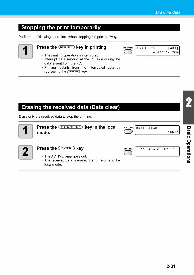
2-31
Drawing data
2
Basic O
peratio
ns
Stopping the print temporarily
Perform the following operations when stopping the print halfway.
1 Press the key in printing.
• The printing operation is interrupted.• Interrupt data sending at the PC side during the
data is sent from the PC.• Printing restarts from the interrupted data by
repressing the key.
Erasing the received data (Data clear)
Erase only the received data to stop the printing.
1 Press the key in the local mode.
2 Press the key.
• The ACTIVE lamp goes out.• The received data is erased then it returns to the
local mode.
< LOCA L . 1 > [ # 0 1 ]w i d t h : 1 2 7 2mm
D A T A C L E A R< E N T >
* * D A T A C L E A R * *

Drawing data
2-32
Cutting a media
For a roll media, two ways are available to cut the media after printing is completed, as follows.
Auto cut
A media is automatically cut after printing is completed.
1 Cut the media automatically after print-ing is completed.
Manual cut
Cut the media at an optional position by using the keys on the operation panel.
1 Press the keys in the local mode.
• It enters the printing origin setting mode.• Feed the media to the position to cut by pressing the key.
2 Press the key.
3 Press the key.
• This machine cuts the media.• It returns to the local mode after cutting is
completed.
• Pay attention so that printed surface does not touch to a floor or other printed surfaces when the media is cut.
• When the take-up device is used, roll up the cut media by operating a switch of the take-up device. (Except Type B)
• For the Auto cut function, it is required to set. (The Auto cut function is set to “OFF" when pur-chased.)
• When the Auto cut function is set to "OFF", cut a media according to the operations of "Manual cut".
OR I G I N S E T U P0 . 0 - - - -
ME D I A CU T< E N T >
ME D I A CU T T I NGP L E A S E WA I T

This section describes the operation procedures for using themachine more conveniently and each setting procedure.
User type ........................................ 3-2Registering the drawing conditions together (Type registration) ............... 3-2Registering Type ............................... 3-2
Setting media compensation........ 3-5Setting media compensation ............. 3-5
Setting print mode ......................... 3-8Setting of the print quality .................. 3-8Setting scanning direction ............... 3-10Setting Logical-seek ........................ 3-11Setting WhiteLay Print ..................... 3-12
Setting drying time ...................... 3-14Setting margins............................ 3-15Setting Priority ............................. 3-16Setting Auto cleaning.................. 3-18Setting cleaning while printing... 3-20Setting media detection .............. 3-22Other settings .............................. 3-24Initializing the settings ................ 3-26
Machine settings.......................... 3-27Setting the deodorize fan ................ 3-28Setting Dryness feeding .................. 3-29Setting Stamp ................................. 3-30Setting Test draw arrange .............. 3-32Change the operation condition of the room temperature ..................... 3-34Setting confirmation feeding ........... 3-35Setting time ..................................... 3-36Setting Unit ..................................... 3-37Setting Machine name .................... 3-38Setting Key buzzer .......................... 3-39
Extension of Ink Expiry Month.... 3-40Extension of Ink Expiry Month ........ 3-40
Switch Setting of Ink Supply Path ............................................... 3-42Confirming machine information 3-44
Displaying Information .................... 3-44
CHAPTER 3
Convenient use

3-2
User typeRegistering the drawing conditions together (Type registration)
The drawing conditions are registered in each type (1-4).The most suitable drawing conditions are settable only by changing the type when replaced by a different type of media, if the drawing conditions that meet the media to be used have been registered in the type.
Example of type registration
Registering Type
1 Press the key in the local mode.
2 Press the key.
3 Select the type (1-4) by pressing the keys then the key.
4 Select and set each item of the list of SET UP functions.
• For the detailed setting procedures, refer to reference pages described in "List of func-tions".
When solvent ink is used. When aqueous ink is used.
Type 1 For Tarpaulin 1 Photo-paper
Type 2 For Tarpaulin 2 For PET 1
Type 3 FF (Flexible Face) For PET 2
Type 4 PVC Synthetic paper
F UNC T I ONS E T U P < E N T >
S E T U PS E L E C T : T Y P E . 1

3-3
User type
3
Co
nven
ient u
se
List of functions
This section describes the outline of each SET UP function registerable to the user type and the setting value. The underlined has been set when purchased.
Function name Set value Outline
MEDIA COMP. ( P.3-5) -255 ~ 0 ~ 255Prints a pattern to correct the feeding rate of media and cor-rects it.
HEATER( P.3-8)
SET TEMP
Pre-Heater
OFF/ 20 ~ 50°C(OFF/ 68 ~ 122°F)
Sets heater conditions.
Print Heater
OFF/ 20 ~ 50°C(OFF/ 68 ~ 122°F)
Post Heater
OFF/ 20 ~ 50°C(OFF/ 68 ~ 122°F)
SET TIMESTANDBY
( NONE/ 0 ~ 90 min10min unit)
OFF TIME( NONE/ 0 ~ 90 min10min unit)
PRINT MODE( P.3-12)
DRAFT Quality STD / FAST / FINE
Sets a print quality level and printing direction.
FINE Quality STD / FAST / FINE
SCAN DIRECTION Bi-D / Uni-D
LOGICAL SEEK ON / OFF
WhiteLay Print OFF/ ON (LEVEL 1~3)
INK LAYERS ( P.3-28) 1 ~ 9Sets the number of layers in which ink is to be applied.
DRYING TIME( P.3-18)
SCAN 0.0 ~ 19.9 secSets the time to wait for ink drying.Draw. END 0 ~ 999 sec
AUTO CUT ( P.3-28) ON / OFFCuts the media automatically after printing.
PRE-FEED ( P.3-28) ON / OFF
Feeds the media back and forth before printing.When sticky media is used, select ON.
MARGIN( P.3-19)
LEFT -10 ~ 0 ~ 85mm (1mm unit) Sets a non-printing area along the right and left edges of the media.RIGHT -10 ~ 0 ~ 85mm (1mm unit)
COLOR PATTERN ( P.3-28) ON / OFFPrints a color pattern for nozzle missing check near the right edge of the media.
REFRESH ( P.3-28)Level 0 (Refresh interval long) ~ 3 (Refresh interval short)
Refreshes the print heads dur-ing printing.
VACUUM ( P.3-28)OFF / STANDARD / WEAK /Little WEAK / STRONG
Sets the absorbability of the media.
FeedSPEED LEVEL ( P.3-28)
10 ~ 100 ~ 200%10%6mm/sec100%60mm/sec200%120mm/sec
Changes the media feeding speed in printing.

User type
3-4
Function name Set value Outline
PRIORITY ( P.3-20)INDIVIDUALLY/ ALL HOST /ALL PANEL
Sets the priority of settings (host / panel)Sets each item of the follow-ings individually when the indi-vidual setting is selected.
• MEDIA COMP.• HEATER• PRINT MODE• INK LAYERS• DRYING TIME• AUTO CUT• PRE-FEED• MARGIN• COLOR PATTERN• REFRESH• VACUUM• FeedSPEED LEVEL
AUTO CLEANING( P.3-22)
ONINTERVAL 10 ~ 1000 ~ 10000 mm Sets the auto cleaning of the
print head every completion of printing.
TYPE NORMAL / SOFT / HARD
OFF
Print.CLEANING( P.3-24)
ONINTERVAL 10 ~ 1000 ~ 10000 mm
Sets the auto cleaning of the print head in printing.
TYPE NORMAL / SOFT / HARD
OFF
MEDIA DETECT( P.3-26)
DETECT METHOD SELECT / WIDTHSets the method for detecting the media.CUTTING DETECT
NONE / BOTH EDGE /LEFT EDGE / RIGHT EDGE
FEED ORIGIN ( P.3-28) ON / OFF
Setting the media feeding direction to LED pointer when changing the printing origin position.

3-5
3
Co
nven
ient u
seSetting media compensation
Correct the feeding rate of media after the type of media is replaced or the temperature of Heater is changed.If the correction value is not appropriate, stripes may appear on the print, thus resulting in a poor print.
Setting media compensation
Print the compensation pattern then correct the feeding rate of media.
1 Set a media.( P.2-6)
2 Press the key in the local mode.
3 Press the key.
4 Select the type (1-4) by pressing the keys.
• When any heater temperature is changed, first make sure that the [ CONSTANT ] lamps light and the preset temperatures have been reached, and then start correction.
• On completion of [MEDIA COMP.] during use of a roll media, the media returns to the printing origin. Then the roll media in the rear of this machine will slacken.Before printing, take up the slack in the roll media by hand; a loose roll media can result in an inferior image quality.
• When printing is to be performed while using the take-up device, set the media first and then perform [MEDIA COMP.]. (Except Type B)
• Print two bands as the compensation pattern.• Adjust so that an even color density is obtained around the boundary between the two bands.
Second band
First band
Media advance direction
F UNC T I ONS E T U P < E N T >
S E T U PS E L E C T : T Y P E . 1

3-6
5 Press the key twice.
6 Print the compensation pattern by pressing the key.
7 Check the compensation pattern then input the compensative value.
Input to " + " : Move to such direction that a spacing between two lines is getting wider.Input to " - " : Move to such direction that a spacing between two lines is getting closer.
• The band moves by approx. 0.1mm every when the compensative value is changed by"20".
8 Press the key.
• Print and check the compensation pattern onceagain.
• Compensate it according to the operations of thestep 7 if compensation is required.
9 Press the key several times to end.
[ 1 ] ME D I A COMP .P R I N T S T A R T : e n t
P R I N T I NGP L E A S E WA I T
[ 1 ] ME D I A COMP .V A L U E = 0
[ 1 ] ME D I A COMP .P R I N T S T A R T : e n t

Setting media compensation
3-7
3
Co
nven
ient u
se
When you need to correct the media feed during printing
The media feeding amount can be corrected even in the remote mode or when printing image data.
1 Press the key in the remote mode.
2 Press the key.
3 Enter the correction amount with and key.
• Correction amount : -500 to 500• The value entered here will be reflected on the correction amount immediately.
4 Press the key.
• The value entered here will be invalid when pressing key in stead of key.
5 Press the key.
• The changed value is registered.• The value entered here will be valid temporarily when pressing key in stead of
key. (If performing media detection again or turning OFF the power supply, thecorrection value will be cleared.)
F E E D COMP E N S A T I ON .0
* R EMO T E . 1 * [ # 0 1 ]* * . * * mm
F E E D COMP E N S A T I ON .0 1
F E E D COMP E N S A T I ON .S A V E : e n t
* R EMO T E . 1 + * [ # 0 1 ]* * . * * mm
This indicates that the media correction was performed in the remote mode.

3-8
Changing the set value of HeaterRough guide for temperature setting (When solvent ink is used)
Changing temperature settings of Heater
Set each item of [SET TEMP] and [SET TIME] .
1 Press the key in the local mode.
2 Press the key.
3 Select the type (1-4) by pressing the key.
Type of ink ES3 ink SS21 ink
Type of media PVC Tarpaulin FF All medias
Pre-heater 40°C 40°C 40°C 35°C
Print-heater 40°C 40°C 40°C 35°C
Post-heater 50°C 50°C 50°C 50°C
• Adjust each heater temperature to a value best suited to the media conditions.• No reference is required for the temperature setting when aqueous color ink is used.
SET TEMPChange the set temperature of the Pre-heater, Print-heater andPost-heater built in the platen.
SET TIME
STANDBY
Set the period of time from when printing is completed to when theheater temperature begins to drop to the preheat temperature.Set value : NONE, 0 ~ 90min (10min unit)• The preheat temperature is preset and cannot be changed.• If the machine receives data at the preheat temperature, the heaters
automatically raise their temperatures up to the preset levels and then the machine starts printing.
• When [NONE] is selected, the temperatures do not drop to the pre-heat level.
OFF TIME
The heaters are turned off in the following case:• If a preset time has passed without printing while the machine is in
standby mode.• With STANDBY- [NONE] selected, when preset time passes without
printing after some printing.Set value : NONE, 0 ~ 90min (10min unit)If the machine receives data with the heaters turned off, the heatersare automatically turned on to raise their temperatures up to the pre-set levels and then the machine starts printing.• With [NONE] selected, the heaters are not turned off.• It turns "OFF" at end of printing if "0min" is set.
F UNC T I ONS E T U P < E N T >
S E T U PS E L E C T : T Y P E . 1

3-9
Changing the set value of Heater
3
Co
nven
ient u
se
4 Press the key.
5 Select [HEATER] by pressing the keys.
6 Press the key twice.
• The heater temperature setting display is dis-played.
7 Set each heater temperature by press-ing the keys.
Heater selecting : by the keysTemperature setting : by the keys
8 Press the key.
9 Select [SET TIME] by pressing the key.
10 Press the key.
11 Set it by pressing the keys.
Item selecting : by the keysTime setting : by the keys
12 Press the key.
13 Press the key several times to end.
• It returns to the local mode.
• Use this machine at 20-35 °C to ensure reliable printing. The heater temperatures may not rise to the set values depending on the ambient temperature.
[ 1 ]ME D I A COMP . < e n t >
[ 1 ]H E A T E R < e n t >
P R E P R T POS T2 5 ° C 2 5 ° C 3 5 ° C
P R E P R T POS T3 5 ° C 4 0 ° C 5 0 ° C
Set temperature :20 ~ 50°C
[ 1 ] H E A T E RS E T T EMP < e n t >
[ 1 ] H E A T E RS E T T I ME < e n t >
S T A ND B Y : O F F T I ME1 0 m i n : NON E
S T A ND B Y : O F F T I ME1 0 m i n : NON E
Set value : NONE , 0 to 90min (10min unit)

3-10
Adjusting suitable temperature adjustment (When solvent ink is used)
This section describes the procedure for setting the heater temperatures properly.The proper heater temperatures depend on the media type and ambient temperature. Set temperatures that are appropriate to the media. For non-coated media or media on which ink is slow to dry, set the heater tem-peratures so that the ink fixing and drying characteristics will be improved.
Wait until the CONSTANT lamps light up.
Set the heater temperatures ( P.3-8)
Correct the media feed rate ( P.3-5)
Yes
NoIs media wrinkled?
Test printing
Does media stick to platen?
Does beading occur?
END
Lower the heater temperatures
Raise the heater temperatures
Move the media back and forth with [ ^ ] and [ v ] keys.
Initially, set higher temperatures
No
No
Yes
Yes

Changing the set value of Heater
3-11
3
Co
nven
ient u
se
In case the heater temperature is too low
When solvent ink is used, this may result in printing failures such as beading or banding if the heater tem-perature or the ink acceptable amount (the ink limit) is too low.
Beading is a phenomenon that adjacent dots attract each other and join. Beading causes speckled patterns or stripes along printing passes (banding.)
Example of beading
The area in 100% magenta looks fine. Generally, the area in 70-100% single color is easily affected by the unevenness of media feed rate. The print shown here, free from unevenness of color in the vicinity of 100% magenta area, signifies that media feeding has been adjusted properly.
In the blue area (100% magenta + 100% cyan), however, speckled patterns and banding occur. This band-ing is a result of beading. If heater temperatures are low or the ink capacity (ink limit) of the media is low, the first dot does not solidify before the second dot lands on the media. As a result, dots bond to each other and unevenness or banding occurs.In order to avoid beading, it is recommended to raise the heater temperatures, to raise the ink capacity (ink limit) of the media, to adjust the ink volume per dot for the media, to increase the number of printing passes and decrease the ink amount for one shot, and/or to gain time by scan wait. Change media if none of the above-mentioned measures works to prevent beading.
Fine looking print
Print with banding
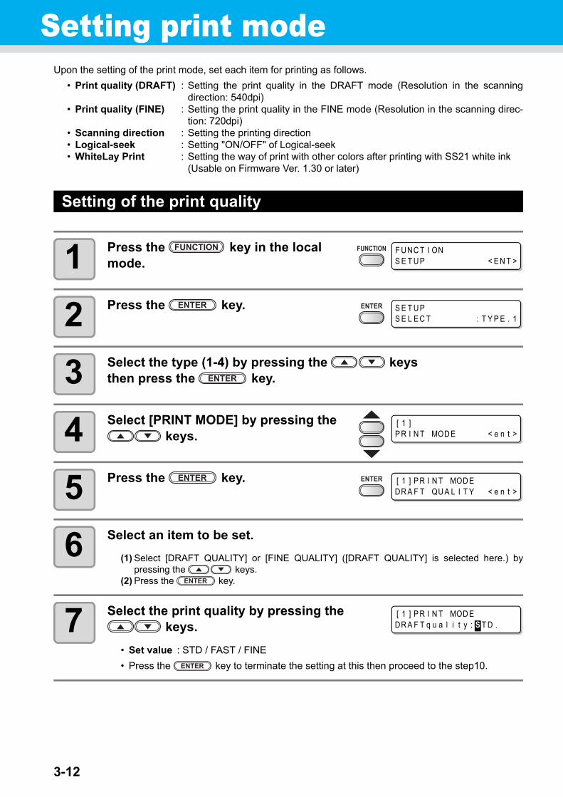
3-12
Setting print modeUpon the setting of the print mode, set each item for printing as follows.
• Print quality (DRAFT) : Setting the print quality in the DRAFT mode (Resolution in the scanningdirection: 540dpi)
• Print quality (FINE) : Setting the print quality in the FINE mode (Resolution in the scanning direc-tion: 720dpi)
• Scanning direction : Setting the printing direction• Logical-seek : Setting "ON/OFF" of Logical-seek• WhiteLay Print : Setting the way of print with other colors after printing with SS21 white ink
(Usable on Firmware Ver. 1.30 or later)
Setting of the print quality
1 Press the key in the local mode.
2 Press the key.
3 Select the type (1-4) by pressing the keys then press the key.
4 Select [PRINT MODE] by pressing the keys.
5 Press the key.
6 Select an item to be set.
(1) Select [DRAFT QUALITY] or [FINE QUALITY] ([DRAFT QUALITY] is selected here.) bypressing the keys.
(2) Press the key.
7 Select the print quality by pressing the keys.
• Set value : STD / FAST / FINE
• Press the key to terminate the setting at this then proceed to the step10.
F UNC T I ONS E T U P < E N T >
S E T U PS E L E C T : T Y P E . 1
[ 1 ]P R I N T MOD E < e n t >
[ 1 ] P R I N T MOD EDR A F T QU A L I T Y < e n t >
[ 1 ] P R I N T MOD EDR A F T q u a l i t y : S T D .

3-13
Setting print mode
3
Co
nven
ient u
se
8When changing the details of printing quality at each resolution.
Select the resolution by pressing the key.
• Set value : 540x720, 540x900, 540x1080 dpi (When “DRAFT” is selected)720x540,720x720,720x1080,720x1440 dpi (When “FINE” is selected)
(1) Select the resolution by pressing the key.(2) Press the key.
9 Select the number of passes and print-ing speed.
(1) Select the number of passes with the keys then press the key.(2) Select the printing speed (“Hi-SPEED” or ”Normal-SPEED”) with the keys.(3) Press the key.
• The set value of the number of passes is different depending on the content of ink set orthe resolution selected at the step 8. Select the number of passes, referring to "Combina-tions of Settable factors".
10 Press the key several times to end.
Combinations of Settable factors
DRAFT quality FINE quality
Resolution(dpi)
4 colors 6 colors Resolution(dpi)
4 colors 6 colors
Pass Speed Pass Speed Pass Speed Pass Speed
540x720dpi
4 Hi-SPEED/Normal-SPEED
8 Hi-SPEED/Normal-SPEED
720x540
6 Hi-SPEED/Normal-SPEED
6 Hi-SPEED/Normal-SPEED
8 16 12 12
16 32 24 24
540x900dpi
10 Hi-SPEED/Normal-SPEED
10 Hi-SPEED/Normal-SPEED
720x720
4 Hi-SPEED/Normal-SPEED
8 Hi-SPEED/Normal-SPEED
20 20 8 16
40 40 16 32
540x1080dpi
6 Hi-SPEED/Normal-SPEED
12 Hi-SPEED/Normal-SPEED
720x1080
6 Hi-SPEED/Normal-SPEED
12 Hi-SPEED/Normal-SPEED
12 24 12 24
24 48 24 48
720x1440
8 Hi-SPEED/Normal-SPEED
16 Hi-SPEED/Normal-SPEED
16 32
32 64
[ 1 ] DR A F T QU A L I T Y5 4 0 x 7 2 0 < e n t >
[ 1 ] DR A F T QU A L I T YP A S S = 8 : S C A N = H i S P E E D

3-14
Setting scanning direction
1 Perform operations up to P.3-12 the step 5.
2 Select [SCAN DIRECTION] by pressing the keys.
3 Press the key.
4 Select the scanning direction by press-ing the keys.
• Set value : Uni-D, Bi-D
5 Press the key.
6 Press the key several times to end.
[ 1 ] P R I N T MOD EDR A F T QU A L I T Y < e n t >
[ 1 ] P R I N T MOD ES C A N D I R E C T I ON < e n t >
[ 1 ] P R I N T MOD ES C A N D I R E C T I ON : U n i - D
[ 1 ] P R I N T MOD ES C A N D I R E C T I ON : B i - D
[ 1 ] P R I N T MOD ES C A N D I R E C T I ON < e n t >

3-15
Setting print mode
3
Co
nven
ient u
se
Setting Logical-seek
The motion of Head varies depending on the set of Logical-seek.
1 Perform operations up to P.3-12 the step 5.
2 Select [LOGICAL SEEK] by pressing the keys.
3 Press the key.
4 Select ON/OFF by pressing the keys.
5 Press the key.
6 Press the key several times to end.
UNI-DIRECTIONAL BI-DIRECTIONAL Movement of heads when LOGICAL seek is OFF
Movement of heads when LOGICAL seek is ON
UNI-DIRECTIONAL BI-DIRECTIONAL
[ 1 ] P R I N T MOD EDR A F T QU A L I T Y < e n t >
[ 1 ] P R I N T MOD EL OG I C A L S E E K < e n t >
[ 1 ] P R I N T MOD EL OG I C A L S E E K : ON
[ 1 ] P R I N T MOD EL OG I C A L S E E K : O F F
[ 1 ] P R I N T MOD EL OG I C A L S E E K < e n t >

3-16
Setting WhiteLay Print
When using SS21 white ink, you can print with other colors after printing with white ink, without returning the media.In this page, set the printing method of white ink and other color ink.
1 Perform operations up to P.3-12 the step 5.
2 Select [WhiteLay Prt] by pressing the keys.
3 Press the key.
4 Select set value by pressing the keys.
• Set value : OFF, ON (LEVEL 1 ~ 3)
Set Value Outline
OFF Printing the white ink and the color ink at the same time.
ON (LEVEL1~3 *1)
*1. This machine cannot set the order of synthesis.
Printing the color ink on the white ink after printing with the white ink.• If a larger number is set for LEVEL 1 to 3, time interval between
printing with white ink and printing with color ink becomes long.• If a large number is set for LEVEL, drying property of white ink
goes up, but printing time becomes long.
• This function can be set only when SS21 ink (6 colors + white) is filled.• Printing time is about two times longer than normal printing.• When printing on the following condition, as usable number of nozzles is limited, printing
speed slows.
Setting of printing quality
Resolution Printing width
DRAFT 540 x 1080 dpi 1541 mm or above
FINE
720 x 1080 dpi1155 mm or above
720 x 1440 dpi
1440 x 1440 dpi 1155 mm or above (577mm for Vd data)
[ 1 ] P R I N T MOD EDR A F T QU A L I T Y < e n t >
[ 1 ] P R I N T MOD EWh i t e L a y P r t < e n t >
[ 1 ] Wh i t e L a y P r tS E L . : O F F
[ 1 ] Wh i t e L a y P r tS E L . : ON ( L E V E L 3 )

Setting print mode
3-17
3
Co
nven
ient u
se
5 Press the key.
6 Press the key several times to end.
[ 1 ] P R I N T MOD EWh i t e L a y P r t < e n t >

3-18
Setting drying timeUpon the setting of drying time, set each item for ink drying as follows.
• SCAN : Set the time to wait for ink drying after each pass. During bidirectional printing, themachine stops temporarily after every scanning back and forth.
• Draw. END : Set the time to wait for ink drying after completion of printing.
1 Press the key in the local mode.
2 Press the key.
3 Select the type (1-4) by pressing the keys then press the key.
4 Select [DRYING TIME] by pressing the keys.
5 Press the key.
6 Set the drying time by pressing the keys.
Item selecting : by the keysTime setting : by the keys
7 Press the key.
8 Press the key several times to end.
F UNC T I ONS E T U P < E N T >
S E T U PS E L E C T : T Y P E . 1
[ 1 ]DR Y I NG T I ME < e n t >
S C A N : D r a w . E ND0 . 0 s : 0 s
S C A N : D r a w . E ND0 . 0 s : 0 s
Scanning :0.0 to 19.9 seconds
Post-printing :0 to 999 seconds
[ 1 ]DR Y I NG T I ME < e n t >

3-19
3
Co
nven
ient u
seSetting margins
Set a non-printing area along the right and left edges of the media.The offset value against the standard margin 15mm is set hereupon.
1 Press the key in the local mode.
2 Press the key.
3 Select the type (1-4) by pressing the keys then press the key.
4 Select [MARGIN] by pressing the keys.
5 Press the key.
6 Set a right and left margin by pressing the keys.
Item selecting : by the keysMargin setting : by the keys
7 Press the key.
8 Press the key several times to end.
• Pay attention to that printing may start on the media press if a right and left margin is set to 5 mm or less when the media press is used in printing.
F UNC T I ONS E T U P < E N T >
S E T U PS E L E C T : T Y P E . 1
[ 1 ]MA RG I N < e n t >
L E F T : R I GH T0 mm : 0 mm
L E F T : R I GH T0 mm : 0 mm
Left margin / Right margin :-10 to 85mm (1mm unit)
[ 1 ]MA RG I N < e n t >

3-20
Setting PriorityFor the following items, the priority is selected either the setting by the machine (by the panel) or the setting by the PC (by the host).
Items to be selected : MEDIA COMP. / HEATER / PRINT MODE / INK LAYERS / DRYING TIME /AUTO CUT / PRE-FEED / MARGIN / COLOR PATTERN / REFRESH / VACUUM / FeedSPEED LEVEL
1 Press the key in the local mode.
2 Press the key.
3 Select the type (1-4) by pressing the keys then press the key.
4 Select [PRIORITY] by pressing the keys.
5 Press the key.
6 Select the set value by pressing the keys.
• Set value : INDIVIDUALLY / ALL HOST / ALL PANEL
• Proceed to the step 7 when [INDIVIDUALLY] is selected. Press the key then proceed to the step 11 when either [ALL HOST] or [ALLPANEL] is selected.
7 Press the key.
• The setting display for the media compensation isdisplayed.
F UNC T I ONS E T U P < E N T >
S E T U PS E L E C T : T Y P E . 1
[ 1 ]P R I OR I T Y < e n t >
[ 1 ] P R I OR I T YS E T U P : A L L P A N E L
[ 1 ] P R I OR I T YS E T U P : I ND I V I DU A L L Y
[ 1 ] P R I OR I T YME D I A COMP . : HOS T

Setting Priority
3-21
3
Co
nven
ient u
se
8 Select either “HOST” or “PANEL” by pressing the keys.
9 Press the key.
• You can also press keys to move between items. Be sure to press the key to register the setting.
10 Set other items by the same operations as the step 8 and 9.
11 Press the key several times to end.
• Even when setting has been made to give priority to the host, the settings made on the machine become effective if there is no instruction from the host.
[ 1 ] P R I OR I T YME D I A COMP . : P A N E L

3-22
Setting Auto cleaningThe machine is settable so that the head cleaning is automatically carried out when printing is completed for the set length.At the completion of printing, the machine counts the length printed after the previous head cleaning and performs the cleaning automatically if required.Reliable output results are always ensured if the heads are always kept clean.The first cleaning is performed immediately before the first printing after the machine is started. Then sub-sequent cleaning is performed every printing on the specified length of media.
When operation interval is 1000 mm (example)
1 Press the key in the local mode.
2 Press the key.
3 Select the type (1-4) by pressing the keys then press the key.
4 Select [AUTO CLEANING] by pressing the keys.
5 Press the key.
Print length : 1.6 m Cleaning (3rd time)
Print length : 0.0 m Cleaning (1st time)
Print length : 0.8 m No cleaning
Print length : 1.6 m Cleaning (2nd time)
Print length : 0.8 m No cleaning
When five copies of an image 80 cm long are printed in series, cleaning is repeated before print-ing each of the 1st, 3rd, and 5th copies.
F UNC T I ONS E T U P < E N T >
S E T U PS E L E C T : T Y P E . 1
[ 1 ]A U T O CR E A N I NG < e n t >
[ 1 ] A U T O CR E A N I NGS E T U P : O F F

Setting Auto cleaning
3-23
3
Co
nven
ient u
se
6 Select “ON” by pressing the keys.
• Proceed to the step 9 when “OFF” is selected.
7 Press the key.
8 Set an interval of cleaning and cleaning type by pressing the keys.
Item selecting : by the keysInterval and Type setting : by the keys
9 Press the key.
10 Press the key several times to end.
• This function does not operate when ink near-end occurs. Solve the ink near-end, referring to P.1-12.
• Depending on the conditions of the heads, etc., the defective printing could not be recovered even performing this function. In this case, contact our service office or distributor.
[ 1 ] A U T O CR E A N I NGS E T U P : ON
I N T E R V A L : T Y P E1 0 0 0 mm : NORMA L
I N T E R V A L : T Y P E1 0 0 0 mm : NORMA L
Interval :10 to 10000mm
Type : NORMALSOFTHARD

3-24
Setting cleaning while printingSet it whether the head cleaning is carried out automatically during printing or not.Upon cleaning during printing, set the cleaning interval to the length printed.The printing is interrupted each in the set length and the head cleaning is carried out automatically.
1 Press the key in the local mode.
2 Press the key.
3 Select the type (1-4) by pressing the keys then press the key.
4 Select [Print.CLEANING] by pressing the keys.
5 Press the key.
6 Select “ON” by pressing the keys.
• Proceed to the step 9 when “OFF” is selected.
7 Press the key.
8 Set an interval of cleaning and cleaning type by pressing the keys.
Item selecting : by the keysInterval and Type setting : by the keys
F UNC T I ONS E T U P < E N T >
S E T U PS E L E C T : T Y P E . 1
[ 1 ]P r i n t . C L E A N I NG < e n t >
[ 1 ] P r i n t . C L E A N I NS E T U P : O F F
[ 1 ] P r i n t . C L E A N I NS E T U P : ON
I N T E R V A L : T Y P E1 0 0 0 mm : NORMA L
I N T E R V A L : T Y P E1 0 0 0 mm : NORMA L
Interval :10 to 10000mm
Type : NORMALSOFTHARD

Setting cleaning while printing
3-25
3
Co
nven
ient u
se
9 Press the key.
10 Press the key several times to end.
• This function does not operate when ink near-end occurs. Solve the ink near-end, referring to P.1-12.
• Depending on the conditions of the heads, etc., the defective printing could not be recovered even performing this function. In this case, contact our service office or distributor.

3-26
Setting media detectionSet the method for detecting a media when the media is set and the detecting type when the media is cut.
1 Press the key in the local mode.
2 Press the key.
3 Select the type (1-4) by pressing the keys then press the key.
4 Select [MEDIA DETECT] by pressing the keys.
5 Press the key.
6 Press the key.
• The setting display for the media detection is dis-played.
7 Select the set value by pressing the keys.
SELECT : Select either a roll media or leaf media by pressing the keys when themedia is detected.
WIDTH : The width of media is only detected without any key input when the media isdetected.(Detecting is started automatically by lowering the clamp lever.)
8 Press the key.
9 Select [CUTTING DETECT] by pressing the key.
F UNC T I ONS E T U P < E N T >
S E T U PS E L E C T : T Y P E . 1
[ 1 ]ME D I A D E T E C T < e n t >
[ 1 ] ME D I A D E T E C TD E T E C T ME T HOD < e n t >
[ 1 ] ME D I A D E T E C TD E T E C T ME T HOD : S E L E C T
[ 1 ] ME D I A D E T E C TD E T E C T ME T HOD < e n t >
[ 1 ] ME D I A D E T E C TCU T T I NG D E T E C T < e n t >

Setting media detection
3-27
3
Co
nven
ient u
se
10 Press the key.
11 Select the set value by pressing the keys.
• Set value : BOTH EDGE / LEFT EDGE / RIGHT EDGE / NONE
12 Press the key.
13 Press the key several times to end.
• If the set value is set to others than “BOTH EDGE” in [CUTTING DETECT], although the cut-ting time is shortened, cutting remainders may happen due to the media skew.
[ 1 ] ME D I A D E T E C TD E T E C T : BO T H E DGE
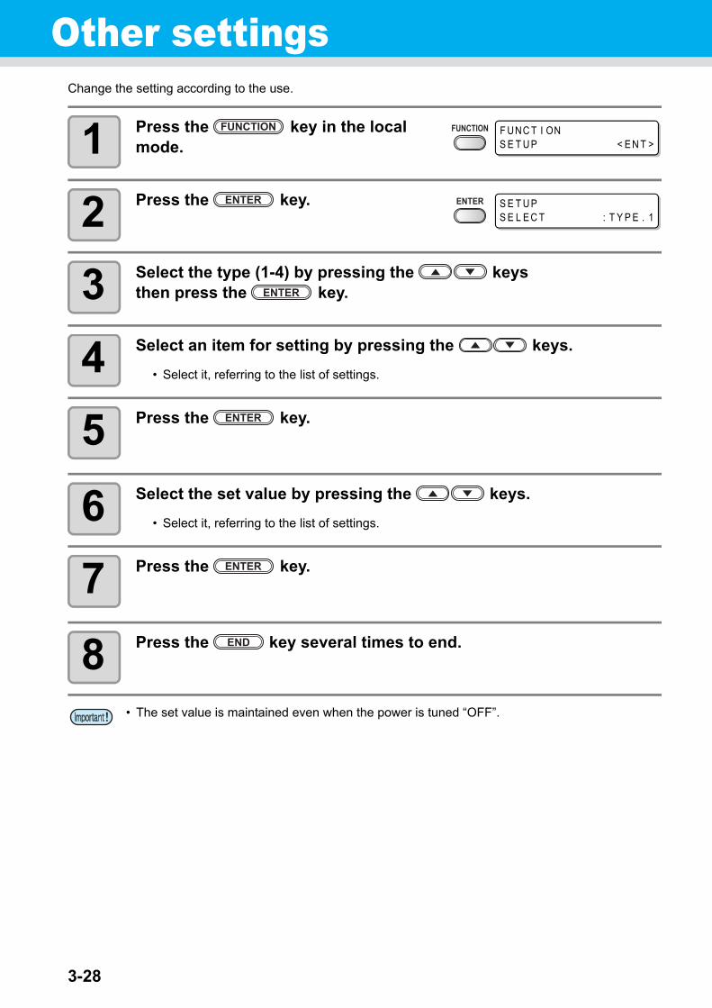
3-28
Other settingsChange the setting according to the use.
1 Press the key in the local mode.
2 Press the key.
3 Select the type (1-4) by pressing the keys then press the key.
4 Select an item for setting by pressing the keys.
• Select it, referring to the list of settings.
5 Press the key.
6 Select the set value by pressing the keys.
• Select it, referring to the list of settings.
7 Press the key.
8 Press the key several times to end.
• The set value is maintained even when the power is tuned “OFF”.
F UNC T I ONS E T U P < E N T >
S E T U PS E L E C T : T Y P E . 1

Other settings
3-29
3
Co
nven
ient u
se
List of Settings
The underlined has been set when purchased.
Item Outline Set value
Setting of Media compensa-tion
Corrects the feeding rate of media Refer to P.3-5
Setting of HeaterSetting Heater temperature
Refer to P.3-8Setting Heater standby time and OFF time
Setting of Printing mode
Setting Print quality
Refer to P.3-12Setting Scanning direction
Setting Logical-seek
Setting WhiteLay Print
Setting of the number of ink layers
Setting the number of layers in which ink is to be applied.
1 ~ 9
Setting of Drying time
Setting the time for drying ink every scanning.
Refer to P.3-18Setting the time for drying ink after the completion of printing.
Setting of Auto cutSetting whether the media is cut automatically or not after printing.
ON / OFF
Setting of Pre-feedingSetting whether the media is carried back and forth or not before printing.
ON / OFF
Setting of MarginsSetting a left margin on the media
Refer to P.3-19Setting a right margin on the media
Setting of Color patternsSetting whether color patterns are printed at the right end of media or not.
ON / OFF
Setting of Refreshing Setting the refreshing level of head. 0 ~ 3
Setting of Adsorption Setting the force adsorbing a mediaSTRONG / STANDARD / Little WEAK / WEAK /OFF
Setting of Feeding speed level
Changing the media feeding speed in printing.
10 ~ 100 ~ 200%
Setting of PrioritySets the priority of settings (host / panel)
INDIVIDUALLY / ALL HOST /ALL PANEL
Setting of Auto cleaningSetting the auto head cleaning oper-ation performed every printing.
Refer to P.3-22
Setting of In-printing clean-ing
Setting the auto head cleaning oper-ation performed during printing.
Refer to P.3-24
Setting of Media detection
Setting the media detecting opera-tion.
Refer to P.3-26Setting the detection conditions at the cutting operation.
Setting of Feed OriginSetting the media feeding direction to LED pointer when changing the print-ing origin position.
ON / OFF

3-30
Initializing the settingsInitialize the settings to the conditions that have been set when purchased. (Set resetting)The set resetting can be executed per type.
1 Press the key in the local mode.
2 Press the key.
3 Select the type (1-4) by pressing the keys then press the key
4 Select [SETUP RESET] by pressing the keys.
5 Press the key.
6 Press the key.
• The set is initialized.
7 Press the key several times to end.
F UNC T I ONS E T U P < E N T >
S E T U PS E L E C T : T Y P E . 1
[ 1 ]S E T U P R E S E T < e n t >
[ 1 ] S E T U P R E S E TR E S E T : e n t

3-31
3
Co
nven
ient u
seMachine settings
It is each type of setting for using this machine more comfortably. [MACHINE SETUP] and [MACHINE SETUP2] are available in this machine.The following items are settable in MACHINE SETUP 1, 2.
Item Set value *1
*1. The setting at the time of purchase is indicated with the underline.
Outline
Mac
hin
e S
etu
p
DEODOR-IZE FAN *2
*2. DEODORIZE FAN is optional.
STOP TIME0 ~ 120 ~ 240min/CONTINUE
Setting the time until the rotation of the exhaustfan is interrupted after the completion of printing.
RENEW ON / OFF Switching the current operation of the exhaust fan.
DRYNESS FEED ON / OFFSetting whether feeding for drying a media is per-formed after the completion of printing or not.
STAMP SETUP ON / OFFSetting to output the output date and drawing con-ditions after the completion of printing.
Waste Ink Warning ON / OFFSetting whether a check message for the wasteink tank is displayed or not.
Test Draw ArrangeFEED DIR. / SCAN DIR.
Setting the deployment direction of the test patternwhen performing test printing repeatedly.
CART.PRIORITY *3
*3. This function is valid only when the 4-color ink set is used.
INK LEVELEXP. DATE
Setting a cartridge to be used first for double car-tridge automatic change function.
ROOM TEMP. *4
*4. This function is available for the firmware Ver.4.60 and later.
Not wait ARR.Wait arrival
Sets the operation when an error indicating thatthe room temperature is out of the usable temper-ature range occurs. ( P.3-38)
Mac
hin
e S
etu
p 2
CONFIRM. FEED ON / OFF
The feeding set for checking the result after testprinting is settable.[BACK FEED] for returning a media to the originalposition by pressing the key is settablewhen set to “ON”.
TIME SET Setting the present date and time.
UNIT SETUP
TEMP.°C (Centigrade)/°F (Fahrenheit)
Setting a unit of temperature indications.
LENGTH mm / inch Setting a unit of length and area indications.
MACHINE NAME 01 ~ 99Setting a machine name (machine No.) for recog-nizing each machine when plural machines areconnected through USB2.0 interface.
KEY BUZZER ON / OFFSetting a buzzer sound of the time when a key ispressed.
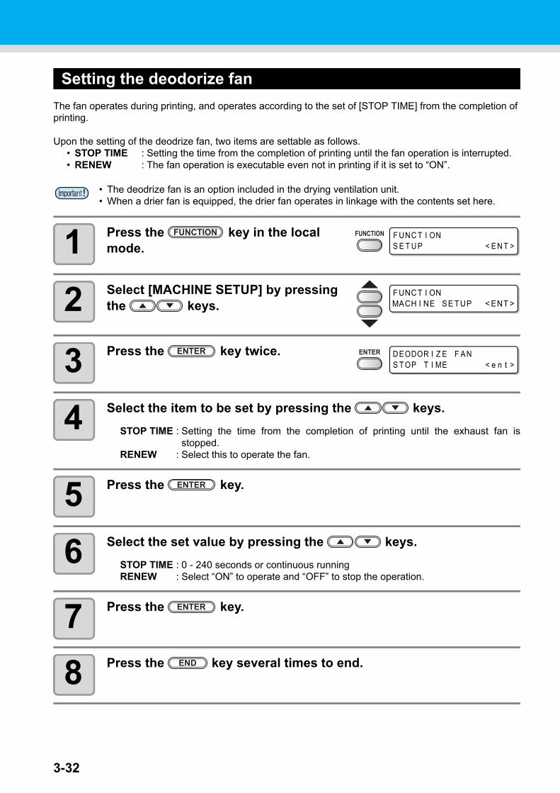
3-32
Setting the deodorize fan
The fan operates during printing, and operates according to the set of [STOP TIME] from the completion of printing.
Upon the setting of the deodrize fan, two items are settable as follows.• STOP TIME : Setting the time from the completion of printing until the fan operation is interrupted.• RENEW : The fan operation is executable even not in printing if it is set to “ON”.
1 Press the key in the local mode.
2 Select [MACHINE SETUP] by pressing the keys.
3 Press the key twice.
4 Select the item to be set by pressing the keys.
STOP TIME : Setting the time from the completion of printing until the exhaust fan isstopped.
RENEW : Select this to operate the fan.
5 Press the key.
6 Select the set value by pressing the keys.
STOP TIME : 0 - 240 seconds or continuous runningRENEW : Select “ON” to operate and “OFF” to stop the operation.
7 Press the key.
8 Press the key several times to end.
• The deodrize fan is an option included in the drying ventilation unit.• When a drier fan is equipped, the drier fan operates in linkage with the contents set here.
F UNC T I ONS E T U P < E N T >
F UNCT I ONMACH I NE SE TUP < ENT >
D EODOR I Z E F A NS T OP T I ME < e n t >

3-33
Machine settings
3
Co
nven
ient u
se
Setting Dryness feeding
Setting whether feeding for drying a media is performed after the completion of printing or not.
1 Press the key in the local mode.
2 Select [MACHINE SETUP] by pressing the keys.
3 Press the key.
4 Select [DRYNESS FEED] by pressing the keys.
5 Press the key.
6 Select ON/OFF by pressing the keys.
7 Press the key.
8 Press the key several times to end.
F UNC T I ONS E T U P < E N T >
F UNCT I ONMACH I NE SE TUP < ENT >
MACH I NE SE TUPD EODOR I Z E F A N < e n t >
MACH I NE SE TUPDR Y N E S S F E E D < e n t >
DR Y N E S S F E E DS E T U P : ON

3-34
Setting Stamp
Set whether information such as the drawing conditions or the date printed is output after the completion of printing or not.
1 Press the key in the local mode.
2 Select [MACHINE SETUP] by pressing the keys.
3 Press the key.
4 Select [STAMP SETUP] by pressing the keys.
5 Press the key.
6 Select ON/OFF by pressing the keys.
7 Press the key.
8 Press the key several times to end.
F UNC T I ONS E T U P < E N T >
F UNCT I ONMACH I NE SE TUP < ENT >
MACH I NE SE TUPD EODOR I Z E F A N < e n t >
MACH I NE SE TUPS T AMP S E T U P < e n t >
S T AMP S E T U PS T AMP : O F F

3-35
Machine settings
3
Co
nven
ient u
se
Examples of Output
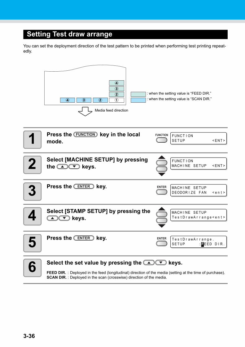
3-36
Setting Test draw arrange
You can set the deployment direction of the test pattern to be printed when performing test printing repeat-edly.
1 Press the key in the local mode.
2 Select [MACHINE SETUP] by pressing the keys.
3 Press the key.
4 Select [STAMP SETUP] by pressing the keys.
5 Press the key.
6 Select the set value by pressing the keys.
FEED DIR. : Deployed in the feed (longitudinal) direction of the media (setting at the time of purchase).SCAN DIR. : Deployed in the scan (crosswise) direction of the media.
Media feed direction
: when the setting value is “FEED DIR.”
: when the setting value is “SCAN DIR.”
F UNC T I ONS E T U P < E N T >
F UNCT I ONMACH I NE SE TUP < ENT >
MACH I NE SE TUPD EODOR I Z E F A N < e n t >
MACH I NE SE TUPT e s t D r a w A r r a n g e < e n t >
T e s t D r a w A r r a n g e .S E T U P : F E E D D I R .

3-37
Machine settings
3
Co
nven
ient u
se
7 Press the key.
8 Press the key several times to end.

3-38
Change the operation condition of the room temperature
If you print in the status that the temperature of the place in which the machine has installed (room temper-ature) is out of the usable temperature range, ink discharging defect or changing color may occur, and it adversely affects the printing quality.Here, select the operation if the room temperature is out of the usable temperature range when printing.
1 Press the key in the local mode.
2 Select [MACHINE SETUP] by pressing the keys.
3 Press the key.
4 Press to select [ROOM TEMP.].
5 Press the key.
6 Press to select a set value.
Not wait ARR. : The error message is displayed for a moment, and printing starts.Wait arrival : After the error message is displayed, wait until the room temperature
reaches the proper value. Then, printing starts.
7 Press the key.
• Press the key several times to end the setting.
• For the details of the usable temperature range, refer to P.6-3 “Available temp.”.• If the room temperature is out of the usable temperature range at the start of printing, the error
message below is displayed to inform you of it.
* * * * ERROR 1 2 0 * * * *ROOM TEMP LOW ( XX ° C )
* * * * ERROR 1 2 1 * * * *ROOM TEMP H I GH ( XX ° C )
* The temperature displayed in error message is the one of inside of the machine. Be careful that it is not actual room temperature.
F UNC T I ONS E T U P < E N T >
F UNCT I ONMACH I NE SE TUP < ENT >
MA CH I N E S E T U PD EODOR I Z E F A N < e n t >
MA CH I N E S E T U PROOM T EMP . < e n t >
ROOM T EMP .S E L : N o t w a i t A RR .
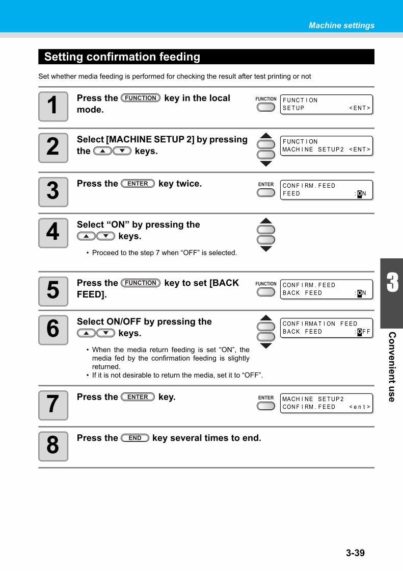
3-39
Machine settings
3
Co
nven
ient u
se
Setting confirmation feeding
Set whether media feeding is performed for checking the result after test printing or not
1 Press the key in the local mode.
2 Select [MACHINE SETUP 2] by pressing the keys.
3 Press the key twice.
4 Select “ON” by pressing the keys.
• Proceed to the step 7 when “OFF” is selected.
5 Press the key to set [BACK FEED].
6 Select ON/OFF by pressing the keys.
• When the media return feeding is set “ON”, themedia fed by the confirmation feeding is slightlyreturned.
• If it is not desirable to return the media, set it to “OFF”.
7 Press the key.
8 Press the key several times to end.
F UNC T I ONS E T U P < E N T >
F UNCT I ONMACH I NE SE TUP 2 < ENT >
CON F I RM . F E E DF E E D : ON
CON F I RM . F E E DB A C K F E E D : ON
CON F I RMA T I ON F E E DB A C K F E E D : O F F
MACH I NE SE TUP 2CON F I RM . F E E D < e n t >

3-40
Setting time
1 Press the key in the local mode.
2 Select [MACHINE SETUP 2] by pressing the keys.
3 Press the key.
4 Select [TIME SET] by pressing the keys.
5 Press the key twice.
6 Input time by the pressing the keys.
Year/Month/Day/Time selecting:by the keys.Year/Month/Day/Time inputting:by the keys.
7 Press the key.
• The input time is indicated.
8 Press the key several times to end.
• The setting of past time is settable only for time up to 8 hours earlier than the presently indi-cated time.
• If future time is set by mistake, the previously set time can be set back by the following opera-tions in step 7.
(1)Press the key in step 7. (The input time and the previously set time are indi-cated.)
(2)Press the key.
Only one change of previous setting can be set back. The time before changed is proceeding by the elapsed time.
F UNC T I ONS E T U P < E N T >
F UNCT I ONMACH I NE SE TUP 2 < ENT >
MACH I NE SE TUP 2CON F I RM . F E E D < e n t >
MACH I NE SE TUP 2T I ME S E T < e n t >
T I ME S E T2 0 1 2 . 1 0 . 0 5 1 5 : 3 0 : 0 0
T I ME S E T2 0 1 2 . 1 0 . 0 5 1 5 : 3 0 : 0 0

3-41
Machine settings
3
Co
nven
ient u
se
Setting Unit
Set a unit of measurement to be used in the machine.
1 Press the key in the local mode.
2 Select [MACHINE SETUP 2] by pressing the keys.
3 Press the key.
4 Select [UNIT SETUP] by pressing the keys.
5 Press the key.
6 Select the unit by pressing the keys.
Item selecting : by the keysUnit setting : by the keys
7 Press the key.
8 Press the key several times to end.
F UNC T I ONS E T U P < E N T >
F UNCT I ONMACH I NE SE TUP 2 < ENT >
MACH I NE SE TUP 2CON F I RM . F E E D < e n t >
MACH I NE SE TUP 2UN I T S E T U P < e n t >
T EMP : L E NG T H° C : mm
MACH I NE SE TUP 2UN I T S E T U P < e n t >

3-42
Setting Machine name
Set a machine name (machine No.) for recognizing each machine when plural machines are connected through USB2.0 interface.
1 Press the key in the local mode.
2 Select [MACHINE SETUP 2] by pressing the keys.
3 Press the key.
4 Select [MACHINE NAME] by pressing the keys.
5 Press the key.
6 Select the machine name (01 - 99) by pressing the keys.
7 Press the key.
8 Press the key several times to end.
F UNC T I ONS E T U P < E N T >
F UNCT I ONMACH I NE SE TUP 2 < ENT >
MACH I NE SE TUP 2CON F I RM . F E E D < e n t >
MACH I NE SE TUP 2MA CH I N E N AME < e n t >
MA CH I N E N AMEJ V 3 3 - 0 1 < e n t >
MA CH I N E N AMEJ V 3 3 - 1 0 < e n t >
MACH I NE SE TUP 2MA CH I N E N AME < e n t >

Machine settings
3-43
3
Co
nven
ient u
se
Setting Key buzzer
Set a buzzer sound of the time when a key is pressed.
1 Press the key in the local mode.
2 Select [MACHINE SETUP 2] by pressing the keys.
3 Press the key.
4 Select [KEY BUZZER] by pressing the keys.
5 Press the key.
6 Select ON/OFF by pressing the keys.
7 Press the key.
8 Press the key several times to end.
• A buzzer sound at Error/Warning/Operation completion cannot be cancelled even when the setting is turned to “OFF”.
F UNC T I ONS E T U P < E N T >
F UNCT I ONMACH I NE SE TUP 2 < ENT >
MACH I NE SE TUP 2CON F I RM . F E E D < e n t >
MACH I NE SE TUP 2K E Y B U Z Z E R < e n t >
K E Y B U Z Z E RS E T U P : ON
K E Y B U Z Z E RS E T U P : O F F
MACH I NE SE TUP 2K E Y B U Z Z E R < e n t >

3-44
Extension of Ink Expiry MonthInk expiry month can be extended for six months from the expired month. When used without extension, ink becomes unusable after two months of the expiry month.
Extension of Ink Expiry Month
The following setting or confirmation screen appears when the power of this machine is turned on, or when expired ink cartridge is set.
1 When a screen shown on the right appears, go to the next step.
2 Press the to select [YES].
• When the ink expiry month is not extended, select[NO]. In this case, the ink will be disabled after twomonths of the expiry month.
3 Press the key.
• Ink expiry month is extended.
• An ink cartridge that is once set [YES] for extension cannot be changed the setting.• To extend multiple inks’ expiry month at a time, set the expired ink cartridges, and then set the
extension.• Extension of ink expiry month may lower the print image quality or print quality such as color
difference or banding. Please understand them when extending ink expiry month.• When initial filling, the ink expired more than two months ago cannot be used.
• When extended six months (six months from the ink expired month) have passed, a message “COMPLETELY EXPIRED” appears and the ink becomes unusable. Immediately replace the ink cartridge with a new one.
• If ink expiry month is extended, the cartridge LED blinks in green while supplying ink from the extended cartridge.
E X T E ND E X P I R E D A T E ?Y E S < > NO
NO T R E COMME ND E D ! !Y E S < > NO
alternately displayed
E X P I R E D A T E E X T E ND E DP R E S S [ E N T ]

Extension of Ink Expiry Month
3-45
3
Co
nven
ient u
se
When a cartridge extended the expiry month is set
When a cartridge extended the expiry month is set and the power is turned on, or when a cartridge extended the expiry month is set to this machine, the following screen appears.
When an ink expiry month is extended
Example: If expiry month of your ink cartridge is February 2014.
• When the expiry month is not extended
• When the expiry month is extended (When extended at the time of )
• To check expired ink, press the key while displaying the screens above alternately.
February March April May or laterPrintable continuously
Not printable continuously
Not printable (Unusable)
A message "Expiration:2MONTH" or "COMPLETELY EXPIRED"appears on the display, and the cartridge lamp lights in red.
A message "Expiration:1MONTH" appears on thedisplay, and the cartridge lamp blinks in red.
A message "Expiration" appears.
February March April May or laterSeptem-ber
Printable continuously
Not printable continuously
Printable continuouslyNot printable (Unusable)
Printable continuously
Not printable continuously
Not printable (Unusable)
Printable continuouslyNot printable (Unusable)
A message "COMPLETELY EXPIRED" appears.
Even if extended at any time from April to August, it is extended for six months from the expiry month
Press the key
E X P I R E D I N K I N U S EP R E S S [ E N T ]
NO T R E COMME ND E D ! !P R E S S [ E N T ]
alternately displayed

3-46
Switch Setting of Ink Supply PathFor the ink supply, condition of the ink cartridge to be used first by the double-cartridge automatic switching function can be selected.This setting is only available for 4-color set.
1 Press the key in the local mode.
2 Select [MACHINE SETUP] by pressing the keys.
3 Press the key.
4 Select [CART.PRIORITY] by pressing the keys.
5 Press the key.
6 Select the condition of ink to be used first by pressing the keys.
INK LEVEL : Low ink cartridge is used firstEXP. DATE : Close-to-date ink cartridge is used first
7 Press the key.
8 Press the key several times to end.
• When expired ink cartridge is set, the expired cartridge is used first regardless of the setting below.
• When the optional bulk ink system (MBIS) is used and the MBIS is set in both slots, the set-ting below is effective.
• When both an ink cartridge and the bulk ink system (MBIS) are set in the supply paths of the same color, see the next page.
F UNC T I ONS E T U P < E N T >
F UNC T I ONMA CH I N E S E T U P < E N T >
MA CH I N E S E T U PC A R T . P R I OR I T Y < e n t >
C A R T . P R I OR I T YS E L E C T : I N K L E V E L

Switch Setting of Ink Supply Path
3-47
3
Co
nven
ient u
se
When both ink cartridge and MBIS are used
When both an ink cartridge and the optional bulk ink system (MBIS) are set in the supply paths of the same color for 4-color ink set, you can select the ink to be used first.
1 Press the key in the LOCAL or the REMOTE mode.
2 Press the key..
3 Press the key to set the supply path and the ink to be used first.
Select the supply path : Press the key.Select the ink to be used first : Press the key.
4 Press the key.
• It enters in the LOCAL or the REMOTE mode.
• Usually, when both an ink cartridge and the bulk ink system (MBIS) are set in the supply path of the same color, the ink in the bulk ink system (MBIS) is used first.
• This setting is only available for 4-color set.• If supply path does not have both ink cartridge and the bulk ink system (MBIS), this function
cannot be set.• Pull out the ink cartridge selected on this function or turn the power on again to disable the
setting.
E S 3 MMCC Y Y K KR EMA I N 3 4 5 6 7 8 9 9
B U L K / C A R T S E L E C T- B B B
Displays the currently supplying ink.B : Bulk ink system (MBIS)C: Ink cartridge- : Only one type is set
B U L K / C A R T S E L E C T- C B B

3-48
Confirming machine informationThe machine information of the machine is confirmable.Confirmable items of the machine information are as follows.
Displaying Information
1 Press the key in the local mode.
• When it is desirable to print the set list of the machine, set a media to the machine.( P.2-6)
2 Select [INFORMATION] by pressing the keys.
3 Press the key.
4 Select the type of information by press-ing the keys.
5 Press the key.
• The information is displayed.• The set contents of the machine is printed when [LIST] is selected.
Item Description
ERROR HISTORYDisplays the history of errors and warnings.Using the or key, the errors and warnings can be displayed oneby one in the order of occurrence.
MAINTE. HISTORY
Displays the records of the date and time when maintenance functionswere used.It displays chiefly manual cleaning functions or automatic cleaning func-tions (by ROUTINE SETUP or SLEEP SET UP).
PRT.modeHISTORYDisplays the information (printing conditions) of the online printing that hasbeen performed up to now since power-on. (Max. 50)Using or key, the display can be changed in the order of printing.
LIST Prints the settings of the machine.
Ink REPL. Report *1
*1. This function is available for the firmware Ver. 4.60 and later.
Prints history of ink used on the machine.
VERSION Displays version information of the machine.
Serial & Dealer No. Displays serial No. and dealer No. of the machine.
F U N C T I O NS E T U P < E N T >
F U N C T I O NI N F O RM A T I O N < E N T >
I N F O RM A T I O NE R R O R H I S T O R Y < e n t >
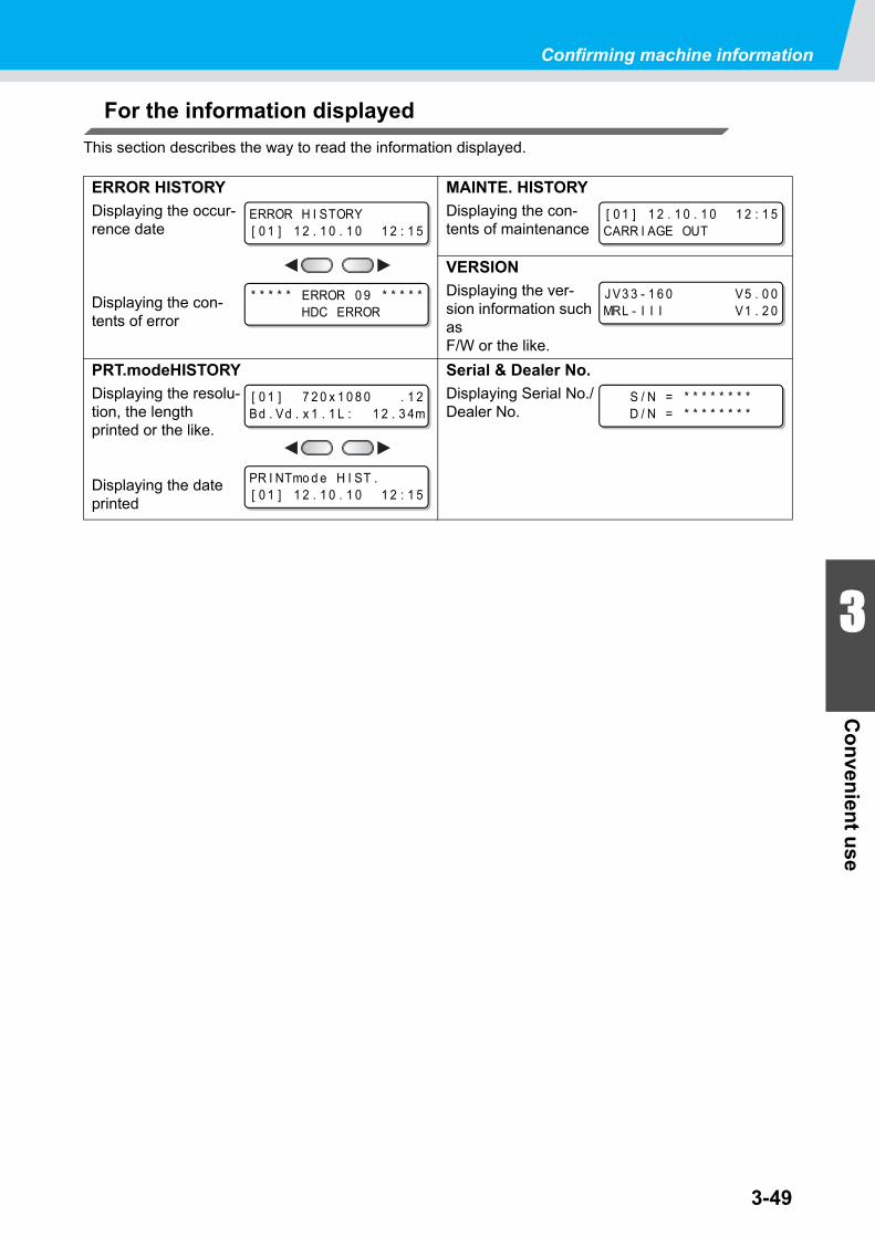
Confirming machine information
3-49
3
Co
nven
ient u
se
For the information displayed
This section describes the way to read the information displayed.
ERROR HISTORY
Displaying the occur-rence date
Displaying the con-tents of error
MAINTE. HISTORY
Displaying the con-tents of maintenance
VERSION
Displaying the ver-sion information such as F/W or the like.
PRT.modeHISTORY
Displaying the resolu-tion, the length printed or the like.
Displaying the date printed
Serial & Dealer No.
Displaying Serial No./Dealer No.
ERROR H I STORY[ 0 1 ] 1 2 . 1 0 . 1 0 1 2 : 1 5
* * * * * ERROR 0 9 * * * * *HDC ERROR
[ 0 1 ] 1 2 . 1 0 . 1 0 1 2 : 1 5CARR I AGE OUT
J V3 3 - 1 6 0 V5 . 0 0MRL - I I I V1 . 2 0
[ 0 1 ] 7 2 0 x 1 0 8 0 . 1 2Bd . Vd . x 1 . 1 L : 1 2 . 3 4m
PR I NTmo d e H I ST .[ 0 1 ] 1 2 . 1 0 . 1 0 1 2 : 1 5
S / N = * * * * * * * *D / N = * * * * * * * *

3-50

This section describes the items required to use this machinemore comfortably, which are the procedures of ink replacing,cleaning or the like.
Maintaining...................................... 4-2Precautions in cleaning ......................4-2Notes on cleaning solution .................4-2Cleaning exterior surfaces .................4-3Cleaning the platen ............................4-3Cleaning the media sensor ................4-4Cleaning the media press ..................4-4
Maintaining Capping station.......... 4-5Cleaning the wiper and ink caps ........4-5Replacing the wiper ............................4-7Prior to Pump tube washing ...............4-8Washing of Head nozzle ..................4-10Cleaning the ink discharge passage (PUMP TUBE WASH) ......................4-12When not using for a long term (CUSTODY WASH) .........................4-14
Cleaning heads and surroundings parts ............................................... 4-16When Nozzle clogged after cleaning ......................................... 4-18
Filling up ink .....................................4-18DISCHARGE & WASH .....................4-19Initial ink fill up ..................................4-21
If the Positions of Dots Shift........ 4-23
Preventing nozzle clogging while power-off ....................................... 4-25
Setting refreshing interval in Sleep mode ................................................4-25Setting tube washing interval in Sleep mode ......................................4-26Setting cleaning interval in Sleep mode ................................................4-27
Setting Routine operations.......... 4-28Setting Routine wiping operations in Standby mode ..................................4-28Setting Refreshing interval in Standby mode ..................................4-30Setting Pump tube washing interval in Standby mode ..............................4-31Setting Cleaning interval in Standby mode ................................................4-32
Other maintenance functions...... 4-34Changing the warning time of wiper replacement .....................................4-34Setting the media remaining display 4-35White Ink Maintenance Function ......4-37To use sublimation transfer ink with more stable quality ...........................4-39If Waste ink tank confirming message is displayed ......................................4-42Changing the ink ..............................4-46
Replacing the cutter blade........... 4-47
CHAPTER 4
Routine Maintenance

4-2
MaintainingBe sure to perform maintenance of the machine periodically or whenever necessary so that the machine can be used with its inherent accuracy for a long time.
Precautions in cleaning
Pay attentions to the following items when the machine is maintained.
Notes on cleaning solution
Use the cleaning liquid dedicated for the ink being used.
• When using the cleaning solution, be sure to wear the supplied protective glasses.
• The ink contains an organic solvent. When performing cleaning, be sure to wear gloves so that no ink will come in contact with your skin.
• Never disassemble the machine. Disassembling it can result in electric shock hazards or dam-age to the machine.Before starting maintenance work, be sure to turn off the power switch and unplug the power cable; otherwise, an unexpected accident may occur.
• Prevent moisture from entering the machine. Moisture inside the machine can cause electric shock hazards or damage to the machine.
• To ensure reliable ink jetting, it is necessary to have the machine perform ejection of a fine amount of ink (flushing) periodically while printing (output) is suspended for an extended period of time.
• When printing is to be suspended for a long time, turn off only the power switch in the front of the machine; leave the main power switch at the rear of the machine turned ON (in the position of | ) and leave the power cable connected.
• If organic solvent ink is mixed with water or alcohol, coagulation occurs.Do not wipe the nozzle face of the heads, the wiper or caps with water or alcohol. Doing so can cause nozzle clogging or machine failure.
• Do not use benzine, thinner, or any chemical agent containing abrasives. Such materials can deteriorate or deform the surface of covers.
• Do not apply lubricating oil or the like to any part inside the machine. Doing so can cause print-ing failure.
• Be careful not to allow the cleaning solution or ink to adhere to covers, as this may cause dete-rioration or discoloring of the surface of covers.
Type of Ink Applicable maintenance washings
SS21 Solvent ink Cleaning solution MS2/ES3/HS kit (SPC-0369)MILD SOLVENT WASHING LIQUID (SPC-0294)[Sold separately]ES3 Solvent ink
Aqueous pigment inkCleaning Liquid Bottle Kit A29 (SPC-0137) [Sold separately]Aqueous Cleaning Liquid Cartridge (SPC-0259) [Sold separately]
Sublimation dye ink
Eco-PA1 ink

4-3
Maintaining
4
Ro
utin
e Main
tenan
ce
Cleaning exterior surfaces
If exterior surfaces of the machine is stained, dampen a soft cloth with water or a neutral detergent diluted with water, squeeze it and wipe the surfaces with the cloth.
Cleaning the platen
On the platen, it is easy to become dirt due to lint, paper dust or the like caused by cutting medias.For a conspicuous stain, wipe it off with a soft-hair brush, a dry cloth, a paper towel or the like.
• If it is stained with ink, wipe it off with a paper towel containing a little amount of the cleaning solution.
• Before starting to clean the platen, make sure that the platen has cooled adequately.• Be sure to clean the slot for media pressing, the slot for paper cutting (the cutter line) or the
like since dust and dirt are easily accumulated in these parts.

Maintaining
4-4
Cleaning the media sensor
A media sensor is located at the platen on the backside. It may cause misdetection of media when dust or the like is accumulated on the sensor.Using a cotton swab, clean the surface of the sensor of dust and dirt.
When cleaning the sensor on the lower surface of the head is cleaned, move the carriage to the left end by the operations of step 1 of P.4-16 "Cleaning the heads and their surrounding parts", and then clean it.
Cleaning the media press
Media feeding may not operate properly in printing if cutting waste, dust or the like is accumulated on the media press, nor may print properly if dust or the like sticks to the nozzle.Clean the media press periodically.
Media sensor Media sensor
The backside of the machine The lower surface of the head
Media press

4-5
4
Ro
utin
e Main
tenan
ceMaintaining Capping station
Maintain Ink cap, Wiper or the like, which are located in the capping station. [ST.MAINTENANCE]
The ink cap and wiper function respectively as follows.• Wiper : Wiping ink sticking to the head nozzle off.• Ink cap : Preventing the head nozzle from clogging due to drying.
As the machine is used, the wiper and ink caps gradually become stained with ink and dust.Clean it with the cleaning solution and a cotton swab unless nozzle missing is cleared even after the head cleaning.If nozzle missing cannot be corrected even after executing the Head Cleaning ( P.2-24) , use Cleaning kit and clean stick.
Cleaning the wiper and ink caps
It is recommended to perform cleaning frequently in order to maintain the high image quality and keep the machine in good condition.
1 Press the key in the local mode.
2 Press the key.
• The carriage moves onto the platen.
3 Open the front cover then remove the wiper.
• Pull out the wiper by holding the projections atboth ends.
Tools required for Maintenance
• Cleaning solutionWhen solvent ink is used:Cleaning solution MS2/ES3/HS kit (SPC-0369)When aqueous ink is used :Cleaning Liquid Bottle Kit A29 (SPC-0137)
• Clean stick • Gloves • Goggles
• Be sure to wear the attached goggles and gloves for works when the maintenance of the cap-ping station is performed. If not, ink may be caught in your eyes during the works.
• Do not move the carriage out of the capping station by hand.• When it is desirable to move the carriage, press the key to execute the carriage-
out. ( P.4-5 the step 1 - 2)
• When SS21 ink is used, the ink sticks around the wiper easily. Clean the wiper and surround-ings about twice in a week (it varies, depending on frequency of use of the machine.)
• Replace the wiper with a new one if it is badly soiled or curled. ( P.4-7)• Be careful not to leave lint of the clean stick. Lint may cause printing failure.
S T . MA I N T E N A NC EC A RR I AGE OU T < e n t >
Projection

4-6
4 Clean the wiper and bracket.
• Wipe ink sticking to the wiper and the bracket offwith a clean stick dipped in the cleaning solution.
5 Clean the wiper slider.
• Wipe ink sticking to the wiper slider off with aclean stick dipped in the cleaning solution.
6 Set the wiper at the original position.
• Insert the wiper by holding both ends of the wiper.
7 Clean the cap rubber and wiper cover.
• Wipe ink sticking to the cap rubber and the wipercover off with a clean stick dipped in the cleaningsolution.
8 Close the front cover then press the key.
• After performing the initial operation, the machinereturns to LOCAL mode.
Performing the station maintenance without key
ST.MAINTENANCE is selectable from the local mode by using the key, not by pressing the key.
Press the key in the local
mode.
Select [MAINTE-NANCE] by press-ing the
keys.
Press the key twice.• It becomes the same condition as the
key is pressed from the local mode.
Wiper
Bracket
Wiper slider
Projection
Cap rubber
Wiper cover
( COV E R OP E N )P R E S S < E N T > K E Y
* B e i n g I n i t i a l i z e d *P L E A S E WA I T

4-7
Maintaining Capping station
4
Ro
utin
e Main
tenan
ce
Replacing the wiper
The wiper is consumable.When the display indicates that it is necessary to replace the wiper, immediately replace the wiper with a new one.Also, wipe ink sticking to the lower surface of the slider off.
1 Press the key in the local mode.
2 Select [WIPER EXCHANGE] by press-ing the keys.
3 Press the key.
• The carriage moves onto the platen.
4 Open the front cover then remove the wiper.
• Pull out the wiper by holding the projections atboth ends.
5 Insert a new wiper.
• Install the wiper by holding the projections at bothends.
6 Close the front cover then press the key.
• After performing the initial operation, the machinereturns to LOCAL mode.
• The wiper to be newly installed is available as an option. Order it from your dealer or a sales office of MIMAKI.
• Do not select [WIPER EXCHANGE] at any time other than when the wiper is to be replaced.Once it is selected, the number of wiper operations that is counted in the machine will be reset.
< L OC A L . 1 > [ # 0 1 ]R e p l a c e a W I P E R <MN T >
S T . MA I N T E N A NC EC A RR I AGE OU T < e n t >
S T . MA I N T E N A NC EW I P E R E X CH A NGE < e n t >
S T . MA I N T E N A NC ECOMP L E T E D : e n t
Projection
Projection
( COV E R OP E N )P R E S S < E N T > K E Y
* B e i n g I n i t i a l i z e d *P L E A S E WA I T

4-8
Prior to Pump tube washing
Prior to washing of the pump tube, it is required that the cleaning solution has been filled within the tube.
Filling Cleaning solution
1 Select [HD.MAINTENANCE] of the maintenance menu.
(1) Press the key in the local mode.(2) Select [MAINTENANCE] by pressing the keys then press the key.(3) Select [HD.MAINTENANCE] by pressing the keys.(4) Press the key.
2 Select [MaintWashLiquid] by pressing the keys.
3 Press the key.
4 Press the key.
• Proceed to the step 6 when a normal cartridgehas been set.
5 Set a cleaning solution cartridge.
6 Press the key.
• Filling of the cleaning solution is started.
• When the following messages are indicated, check the waste ink tank, and then operate it, referring to P.4-42 "If Waste ink tank confirming message is displayed" according to the situa-tion.
C o n f i r m a w a s t e t a n kC o n t i n u e < > E x c h a n g e
C o n f i r m a w a s t e t a n kE x c h a n g e : e n t
HD . MA I N T E N A NC EM a i n t Wa s h L i q u i d < e n t >
M a i n t Wa s h L i q u i dF I L L I NG U P < e n t >
M a i n t Wa s h L i q u i dC A R T R I DGE : n o n e
When "END" is indicated :The cleaning solution is not left. Replace it with a new cleaning solu-tion cartridge.
When an abnormal condition is indicated :
The cartridge that has been set is not a cleaning solution cartridge.
M a i n t Wa s h L i q u i dF I L L I NG U P S T A R T : e n t

4-9
Maintaining Capping station
4
Ro
utin
e Main
tenan
ce
Discharging Cleaning solution
Perform the following operations to discharge the cleaning solution within the tube.
1 Select [HD.MAINTENANCE] of the maintenance menu.
(1) Press the key in the local mode.(2) Select [MAINTENANCE] by pressing the keys then press the key.(3) Select [HD.MAINTENANCE] by pressing the keys.(4) Press the key.
2 Select [MaintWashLiquid] by pressing the keys.
3 Press the key.
4 Select [DISCHARGE] by pressing the keys.
5 Press the key.
• Proceed to the step 7 when the cartridge hasbeen removed.
6 Remove the cartridge.
7 Press the key.
• Discharging of the cleaning solution is started.
HD . MA I N T E N A NC EM a i n t Wa s h L i q u i d < e n t >
M a i n t Wa s h L i q u i dF I L L I NG U P < e n t >
M a i n t Wa s h L i q u i dD I S CH A RGE < e n t >
M a i n t Wa s h L i q u i dT h e r e i s a C A R T R I DGE
M a i n t Wa s h L i q u i dD I S CH A RGE S T A R T : e n t

4-10
Washing of Head nozzle
Perform cleaning of the nozzles in the heads to prevent them being clogged with coagulated ink.
1 Press the key in the local mode.
2 Select [NOZZLE WASH] by pressing the keys.
3 Press the key.
• The carriage moves onto the platen.
4 Clean the wiper and the bracket.
(1) Open the front cover then pull out it by holding projections at both ends of the wiper.(2) Clean it with a clean stick dipped in the cleaning solution.
( Aqueous ink : SPC-0137, Solvent ink : SPC-0369)(3) Insert it in the original position by holding the projections at both ends of the wiper.
5 Press the key.
Make sure the followings in
advance.
Is [NEAR END] or [INK END] displayed ?• The cleaning solution or ink is absorbed in washing.
At this time, washing is unable to operate if the ink end or near-end is detected.
• Replace it with a cartridge undetected for the ink end or the like.
S T . MA I N T E N A NC EC A RR I AGE OU T < e n t >
S T . MA I N T E N A NC ENO Z Z L E WA S H < e n t >
W I P E R C L E A N I NGCOMP L E T E D ( N E X T ) : e n t
Projection
F i l l t h e l i q u i dCOMP L E T E D ( N E X T ) : e n t
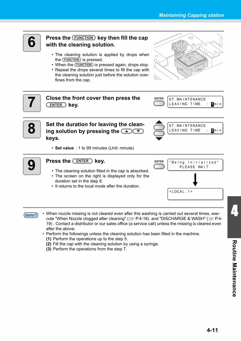
4-11
Maintaining Capping station
4
Ro
utin
e Main
tenan
ce
6 Press the key then fill the cap with the cleaning solution.
• The cleaning solution is applied by drops whenthe is pressed.
• When the is pressed again, drops stop.• Repeat the drops several times to fill the cap with
the cleaning solution just before the solution over-flows from the cap.
7 Close the front cover then press the key.
8 Set the duration for leaving the clean-ing solution by pressing the keys.
• Set value : 1 to 99 minutes (Unit: minute)
9 Press the key.
• The cleaning solution filled in the cap is absorbed.• The screen on the right is displayed only for the
duration set in the step 8.• It returns to the local mode after the duration.
• When nozzle missing is not cleared even after this washing is carried out several times, exe-cute "When Nozzle clogged after cleaning" ( P.4-18) and "DISCHARGE & WASH" ( P.4-19) . Contact a distributor or our sales office (a service call) unless the missing is cleared even after the above.
• Perform the followings unless the cleaning solution has been filled in the machine.(1) Perform the operations up to the step 5.(2) Fill the cap with the cleaning solution by using a syringe.(3) Perform the operations from the step 7.
S T . MA I N T E N A NC EL E A V I NG T I ME : 1 m i n
S T . MA I N T E N A NC EL E A V I NG T I ME : 2 m i n
* B e i n g I n i t i a l i z e d *P L E A S E WA I T
< L OC A L . 1 >

4-12
Cleaning the ink discharge passage (PUMP TUBE WASH)
Perform washing of the ink discharge passage (the pump tube) periodically to prevent ink from clogging due to the coagulation of ink within the ink discharge passage.
1 Press the key in the local mode.
2 Select [PUMP TUBE WASH] by press-ing the keys.
3 Press the key.
• The carriage moves onto the platen.• Repeat the idle absorbing operation (Absorbing for 5 seconds and interrupting for 10 sec-
onds) until washing works are completed.
4 Open the front cover.
5 Press the key to fill the cap with the cleaning solution.
• The cleaning solution is applied by drops whenthe is pressed.
• When the is pressed again, drops stop.• During the idle absorbing is interrupted, repeat the
drops several times to fill the cap with the cleaningsolution just before the solution overflows from thecap.
• When the following messages are indicated, check the waste ink tank, and then operate it, referring to P.4-42 "If Waste ink tank confirming message is displayed" according to the situa-tion.
C o n f i r m a w a s t e t a n kC o n t i n u e < > E x c h a n g e
C o n f i r m a w a s t e t a n kE x c h a n g e : e n t
S T . MA I N T E N A NC EC A RR I AGE OU T < e n t >
S T . MA I N T E N A NC EP UMP T U B E WA S H < e n t >
S T . MA I N T E N A NC ECOMP L E T E D : e n t
Front cover

4-13
Maintaining Capping station
4
Ro
utin
e Main
tenan
ce
6 Close the front cover and press the key.
• It returns to the local mode after the idle absorbingis performed for 30 seconds.
• Perform the followings unless the cleaning solution has been filled in the machine.(1) Perform the operations until the step 4.(2) Fill the cap with the cleaning solution by using a syringe.(3) Perform the operations from the step 6.
* B e i n g I n i t i a l i z e d *P L E A S E WA I T
< L OC A L . 1 >

4-14
When not using for a long term (CUSTODY WASH)
When the operation of the machine is to be suspended for a week or more, use the [CUSTODY WASH] function to clean the nozzles in the heads and the ink discharge passage.After the cleaning, store the machine properly.
1 Press the key in the local mode.
2 Select [CUSTODY WASH] by pressing the keys.
3 Press the key.
• The carriage moves onto the platen.
4 Clean the wiper and the bracket.
(1) Open the front cover then pull out it by holding projections at both ends of the wiper.(2) Clean it with a clean stick dipped in the cleaning solution.
( Aqueous ink : SPC-0137, Solvent ink : SPC-0369)(3) Insert it in the original position by holding the projections at both ends of the wiper.
Check the follow-ings in advance.
Is [NEAR END] or [NEAR END] displayed ?• The cleaning solution or ink is absorbed in washing.
At this time, washing is unable to operate if the ink end or near-end is detected.
• Replace it with a cartridge undetected for the ink end or the like.
• When the following messages are indicated, check the waste ink tank, and then operate it, referring to P.4-42 "If Waste ink tank confirming message is displayed" according to the situa-tion.
C o n f i r m a w a s t e t a n kC o n t i n u e < > E x c h a n g e
C o n f i r m a w a s t e t a n kE x c h a n g e : e n t
S T . MA I N T E N A NC EC A RR I AGE OU T < e n t >
S T . MA I N T E N A NC ECU S T OD Y WA S H < e n t >
W I P E R C L E A N I NGCOMP L E T E D ( N E X T ) : e n t
Projection

Maintaining Capping station
4-15
4
Ro
utin
e Main
tenan
ce
5 Press the key.
6 Press the key to fill the cap with the cleaning solution.
• The cleaning solution is applied by drops whenthe is pressed.
• When the is pressed again, drops stop.• Repeat the drops several times to fill the cap with
the cleaning solution just before the solution over-flows from the cap.
7 Close the front cover and press the key.
8 Set the duration for leaving the clean-ing solution by pressing the keys.
• Set value : 1 to 99 minutes (Unit: minute)
9 Press the key.
• Perform the nozzle cleaning.• On completion of the nozzle cleaning, the head
moves to above the platen.
10 Open the front cover.
11 Press the key to fill the cap with the cleaning solution.
• The cleaning solution is applied to the cap by drops when the is pressed.• When the is pressed again, drops stop.• During the idle absorbing is interrupted, repeat the drops several times to fill the cap with
the cleaning solution just before the solution overflows from the cap.
12 Close the front cover and press the key.
• It returns to the local mode after the initial opera-tion.
F i l l t h e l i q u i dCOMP L E T E D ( N E X T ) : e n t
S T . MA I N T E N A NC EL E A V I NG T I ME : 1 m i n
S T . MA I N T E N A NC EL E A V I NG T I ME : 2 m i n
* B e i n g I n i t i a l i z e d *P L E A S E WA I T
* B e i n g I n i t i a l i z e d *P L E A S E WA I T
< L OC A L . 1 >

4-16
Cleaning heads and surroundings partsTake great care, especially during cleaning, not to damage the heads, which employ very precise mecha-nisms. Using a clean stuck, rub off the gelatinous ink that may be adhering to the lower part of the slider and surrounding parts of the heads. In doing so, never rub the nozzle part of the heads.
1 Select [CR.MAINTENANCE] of the maintenance menu.
(1) Press the key in the local mode.(2) Select [MAINTENANCE] by pressing the keys then press the key.(3) Select [CR.MAINTENANCE] by pressing the keys then press the
key.(4) Press the key.
• The carriage moves to the left end of the machine body.
2 Open the maintenance cover.
(1) Turn four screws that fix the maintenancecover to the left, and remove them.
(2) Remove the maintenance cover.
• If the maintenance cover is hard to remove, use the supplied screwdriver.
3 Wipe ink sticking to the side of the head off with a clean stick.
Tools required for cleaning • Clean stick • Gloves • Goggles
• Be sure to wear the attached goggles and gloves for works when cleaning is performed. If not, ink may be caught in your eyes during the works.
• An organic solvent is used in ink. Wash your eyes and skins with plenty water immediately when you get ink on skins or in eyes.
Screw
Screw
Maintenance cover
Rotate itleft.
Clean the side surface of the head (shown in deep gray) with a clean stick.
The nozzle part (Never touch it.)
Clean this with a clean stick or waste cloth.

Cleaning heads and surroundings parts
4-17
4
Ro
utin
e Main
tenan
ce
4 Press the key after the clean-ing.
5 Close the maintenance cover then press the key.
• It returns to the local mode after the initial opera-tion.
• When SS21 ink is used, the ink sticks around the wiper easily. Clean the wiper and surround-ings about twice in a week (it varies, depending on frequency of use of machine.)
C l o s e a c o v e r
( COVER OPEN )PRESS <ENT> KEY
* Be i n g I n i t i a l i z e d *PLEASE WA I T

4-18
When Nozzle clogged after cleaningWhen the nozzle clogging is not improved even after the head cleaning( P.2-24) or the head nozzle washing ( P.4-10), execute two functions as follows.
Filling up ink
1 Select [HD.MAINTENANCE] of the maintenance menu.
(1) Press the key in the local mode.(2) Select [MAINTENANCE] by pressing the keys then press the key.(3) Select [HD.MAINTENANCE] by pressing the keys.(4) Press the key.
2 Press the key.
• Ink filling is automatically started.
• It returns to the display on the right when the ink filling is completed.
3 Press the key several times to end.
FILL UP INK • Supplies ink to correct nozzle clogging.
DISCHARGE&WASH • Washes the heads, dampers and ink tubes cleaning solution car-tridge (option). ( P.4-19)
F I L L I NG U P0 0 : 0 0
HD . MA I N T E N A NC EF I L L U P I N K < e n t >

4-19
When Nozzle clogged after cleaning
4
Ro
utin
e Main
tenan
ce
DISCHARGE & WASH
Discharge ink from the heads, dampers and ink tubes, and then wash them.
1 Select [HD.MAINTENANCE] of the maintenance menu.
(1) Press the key in the local mode.(2) Select [MAINTENANCE] by pressing the keys then press the key.(3) Select [HD.MAINTENANCE] by pressing the keys.(4) Press the key.
2 Select [DISCHARGE&WASH] by press-ing the keys.
3 Press the key.
4 Remove the ink cartridge.
• The ink left in the head or tube is discharged to the waste ink tank.
• The display on the right is displayed after dis-charging.
5 Set the cleaning solution cartridge to the ink station.
• Absorbing of the cleaning solution is started.• The display on the right is displayed after absorb-
ing.
• To use this function, the dedicated cleaning solution ( P.4-2"Notes on cleaning solution") is required. In addition, before performing the work, check whether ink to be filled again remains or not.
• When the following messages are indicated, check the waste ink tank, and then operate it, referring to P.4-42 "If Waste ink tank confirming message is displayed" according to the situa-tion.
C o n f i r m a w a s t e t a n kC o n t i n u e < > E x c h a n g e
C o n f i r m a w a s t e t a n kE x c h a n g e : e n t
HD . MA I N T E N A NC ED I S CH A RGE &WA S H < e n t >
R e m o v e : I n k C a r t r i d g e sMMCC Y Y K K
* D I S CH A RGE *0 0 : 0 0
S e t : Wa s h i n g C a r t r i d g e1 2 3 4 5 6 7 8
* A B SOP R P T I ON *0 0 : 0 0
R e m o v e : C a r t r i d g e s1 2 3 4 5 6 7 8

4-20
6 Remove the cleaning solution car-tridge.
• The ink left in the head or tube is discharged to the waste ink tank.
• The right display on the right is displayed after dis-charging.
7 Set the cleaning solution cartridge to the ink station.
• Absorbing of the cleaning solution is started.• The display on the right is displayed after absorb-
ing.
8 Remove the cleaning solution car-tridge.
• The ink left in the head or tube is discharged to the waste ink tank.
• The right display on the right is displayed after dis-charging.
• Check the condition of waste ink tank, and then select whether the washing is terminatedor restarted.
• When the washing is restarted, return to the step 5 by pressing the key.
9 Press the key.
10 Press the key several times to end.
* D I S CH A RGE *0 0 : 0 0
S e t : Wa s h i n g C a r t r i d g e1 2 3 4 5 6 7 8
* A B SOP R P T I ON *0 0 : 0 0
R e m o v e : C a r t r i d g e s1 2 3 4 5 6 7 8
* D I S CH A RGE *0 0 : 0 0
M a i n t . Wa s h L i q u i dE ND < > D I S CH A RGE

4-21
When Nozzle clogged after cleaning
4
Ro
utin
e Main
tenan
ce
Initial ink fill up
Perform the initial fill of ink by the following operations after [DISCHARGE & WASH].
1 Turn the power of the machine on.
• When the power is turned on, the firmware version is displayed following [BOOT].
2 Select the ink type to be filled by press-ing the keys.
• To check the state of the cartridge, press the key. ( P.5-5)
3 Select the ink set (a filling color) to be filled by pressing the keys.
• You cannot change the current ink set to other ink set yourselves.
• If you want to change the ink set, contact sales office of MIMAKI.
4 Press the key.
BOO T
J V 3 3 - 1 6 0 V * . * *
P l e a s e Wa i t
I N K T Y P EE S 3 S o l
E S 3 I N K S E T4 - C o l o r ( MMCC Y Y K K )
S e t : E S 3 - 4 c o l o r I n k- - - - - - - -

When Nozzle clogged after cleaning
4-22
5 Set an ink cartridge to the ink station.
• When the ink cartridge is set, filling is automati-cally started.
• Upon the ink station, the inserting location is allocated for each ink color. Set the ink car-tridge according to the cartridge label under the ink station.
6 It returns to the local mode when the ink filling is completed.
If ink is not filled in step 5
If [INK NEAR END], [INK END] or other ink errors occur, it does not start ink filling.
If ink filling is not started in step 5
(1) Press the key to go back to the display of step 2.(2) Press the key to check the state of the ink cartridge.(3) Solve an ink error or others ( P.5-5), operate from step 2 again.
• If blurring or missing is found in printing after initial fill of ink, "Head Cleaning"( P.2-24) or "Filling up ink"( P.4-18) .
S e t : E S 3 - 4 c o l o r I n k- - C - Y - K K
F I L L I NG U P NOW .0 0 : 0 0
The front side
4 colors model:
6 colors model:
6 colors + White model (SS21):
7 colors model (Eco-PA1):
8 colors model (ES3):for the firmware V.4.60 and later
< L OC A L . 1 > [ # 0 1 ]w i d t h : * * * * mm

4-23
4
Ro
utin
e Main
tenan
ceIf the Positions of Dots Shift...
When the thickness of the media, the height of the head, or the type of the ink used is changed, follow the steps below and adjust the ink drop position for Bi-directional (Bi) printing to print properly.
Example of Pattern printing
1 Set a media, and then set the printing origin. ( P.2-6)
• For printing the pattern, a larger media than 500mm width x 400mm feeding is required.
2 Select [DROP POSITION] of the maintenance menu.
(1) Press the key in the local mode.(2) Select [MAINTENANCE] by pressing the keys then press the key.(3) Select [DROP POSITION] by pressing the keys.(4) Press the key.
3 Press the key to start the pat-tern printing.
• Plural pattern types are printed. (in order of printed, called as Pattern 1, 2, 3...)
4 Correct the dot position of the pattern 1 by pressing the keys.
• Correction value : -40 to 40• Check the test pattern. A correction value is at the position where an outward way and a
return way are on one line.• If the correction value is not between -40 and 40, adjust the height of head then redo the
operations from the step 2.
5 Press the key.
The dots at the fourth position counted from the zero position in the positive direction form a straight line.In this case, the dot position correction value is 4.0.
Output direction
P R I N T I N GP L E A S E WA I T
D R O P P O S I T I O NP A T T E R N 1 = 0 . 0

If the Positions of Dots Shift...
4-24
6 As the same as the step 4, correct the dot position of the from pat-tern 2 then press the key.
7 Press the key several times to end.

4-25
4
Ro
utin
e Main
tenan
cePreventing nozzle clogging while power-off
Even while the power switch is off, the machine starts periodically and executes various functions to prevent nozzle clogging. [SLEEP SETUP] includes the following functions.
Setting refreshing interval in Sleep mode
Set the interval at which the nozzles will eject a little volume of ink to prevent nozzle clogging.
1 Select [SLEEP SETUP] of the maintenance menu.
(1) Press the key in the local mode.(2) Select [MAINTENANCE] by pressing the keys then press the key.(3) Select [SLEEP SETUP] by pressing the keys.
2 Press the key.
3 Press the key.
4 Set the refreshing interval by pressing the keys.
• Set value : OFF, 1 - 168 hours
5 Press the key.
6 Press the key several times to end.
Function name Descriptions
REFRESHSet the interval at which refreshing operation is to be performedperiodically.
PUMP TUBE WASHSet the interval at which cleaning of the pump tubes is to be per-formed periodically.
CLEANINGSet the cleaning type and the interval at which cleaning operationis to be performed periodically.
• During the right message is displayed, the operation set in the sleep setting is not carried out. Perform the operations of P.4-43 if required.
• When the power switch on the front of the machine is turned off, check the waste ink tank.
< L OC A L . 1 > [ # 0 1 ]C h e c k w a s t e i n k <MN T >
S L E E P S E T U PR E F R E S H < e n t >
S L E E P S E T U PR E F R E S H i n t e r v a l = 1 h
S L E E P S E T U PR E F R E S H i n t e r v a l = 1 0 h
S L E E P S E T U PR E F R E S H < e n t >

4-26
Setting tube washing interval in Sleep mode
Set the interval at which cleaning of the caps and pump tubes is to be performed using the cleaning solution during sleep mode.
1 Select [SLEEP SETUP] of the maintenance menu.
(1) Press the key in the local mode.(2) Select [MAINTENANCE] by pressing the keys then press the key.(3) Select [SLEEP SETUP] by pressing the keys.(4) Press the key.
2 Select [PUMP TUBE WASH] by press-ing the keys.
3 Press the key.
4 Set the tube washing interval by press-ing the keys.
• Set value : OFF, 1 - 168 hours
5 Press the key.
6 Press the key several times to end.
• When the cleaning solution has not been filled in the machine, the right display is displayed at the step 5. Fill the cleaning solution ( P.4-8) then redo the operations from the step 1.
S L E E P S E T U PP UMP T U B E WA S H < e n t >
S L E E P S E T U PWA S H I N T E R V A L = 1 h
S L E E P S E T U PWA S H I N T E R V A L = 4 h
S L E E P S E T U PP UMP T U B E WA S H < e n t >
* * Wa s h i n g L i q u i d * *
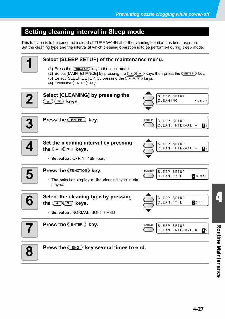
Preventing nozzle clogging while power-off
4-27
4
Ro
utin
e Main
tenan
ce
Setting cleaning interval in Sleep mode
This function is to be executed instead of TUBE WASH after the cleaning solution has been used up.Set the cleaning type and the interval at which cleaning operation is to be performed during sleep mode.
1 Select [SLEEP SETUP] of the maintenance menu.
(1) Press the key in the local mode.(2) Select [MAINTENANCE] by pressing the keys then press the key.(3) Select [SLEEP SETUP] by pressing the keys.(4) Press the key.
2 Select [CLEANING] by pressing the keys.
3 Press the key.
4 Set the cleaning interval by pressing the keys.
• Set value : OFF, 1 - 168 hours
5 Press the key.
• The selection display of the cleaning type is dis-played.
6 Select the cleaning type by pressing the keys.
• Set value : NORMAL, SOFT, HARD
7 Press the key.
8 Press the key several times to end.
S L E E P S E T U PC L E A N I NG < e n t >
S L E E P S E T U PC L E A N . I N T E R V A L = 1 h
S L E E P S E T U PC L E A N . I N T E R V A L = 4 h
S L E E P S E T U PC L E A N . T Y P E : NORMA L
S L E E P S E T U PC L E A N . T Y P E : SO F T
S L E E P S E T U PC L E A N . I N T E R V A L = 4 h

4-28
Setting Routine operationsTroubles such as ink clogging or the like are preventable by performing each periodical operation in the condition of the power ON. (Initial setting) The [ROUTINE SETUP] function is available for the following items :
Setting Routine wiping operations in Standby mode
Ink dew condensation on the nozzle surface is preventable by performing the wiping operation automati-cally when the number of scans reaches the set value in printing.
In the following cases, ink splashing, ink dropping or nozzle missing may occur on printing.It is recommended to maintain the comfortable printing condition at all times by setting the periodic wiping.
• When the print heater has been set at high temperature.• When the printing ink amount has been set plenty (High density, Double printing, etc.)
The cause of these phenomena is such that the ink of the print is heated by the print heater immediately after printing and evaporated solvent may condense on the nozzle face.The greater the difference between the setting temperature of the print heater and the ambient temperature is, the more easily ink can condense.
1 Select [ROUTINE SETUP] of the maintenance menu.
(1) Press the key in the local mode.(2) Select [MAINTENANCE] by pressing the keys then press the key.(3) Select [ROUTINE SETUP] by pressing the keys.
2 Press the key.
3 Press the key.
Function name Descriptions
ROUTINE WIPINGWhile printing, the nozzle surface is wiped with a certain interval to removedew drops.It is possible to set [SCAN COUNT] and [TEMP difference].
REFRESHSet the interval at which refreshing operation is to be performed periodicallyin Standby mode.
PUMP TUBE WASHSet the interval at which cleaning of the pump tubes is to be performed peri-odically in Standby mode.
CLEANINGSet the cleaning type and the interval at which cleaning operation is to be per-formed periodically in Standby mode.
• During the right message is displayed, the operation set in the periodic setting is not carried out except [ROUTINE WIPING]. Perform the operations of P.4-43 if required.
• When the power switch on the front of the machine is turned off, check the waste ink tank.
< L OC A L . 1 > [ # 0 1 ]C h e c k w a s t e i n k <MN T >
ROU T I N E S E T U PROU T I N E W I P I NG < e n t >
ROU T I N E W I P I NGS C A N COUN T < e n t >
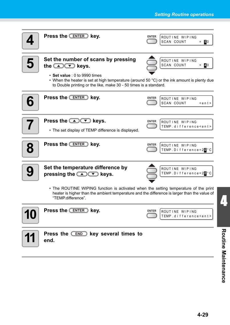
4-29
Setting Routine operations
4
Ro
utin
e Main
tenan
ce
4 Press the key.
5 Set the number of scans by pressing the keys.
• Set value : 0 to 9990 times• When the heater is set at high temperature (around 50 °C) or the ink amount is plenty due
to Double printing or the like, make 30 - 50 times is a standard.
6 Press the key.
7 Press the keys.
• The set display of TEMP difference is displayed.
8 Press the key.
9 Set the temperature difference by pressing the keys.
• The ROUTINE WIPING function is activated when the setting temperature of the printheater is higher than the ambient temperature and the difference is larger than the value of“TEMP.difference”.
10 Press the key.
11 Press the key several times toend.
ROU T I N E W I P I NGS C A N COUN T = 5 0
ROU T I N E W I P I NGS C A N COUN T = 4 0
ROU T I N E W I P I NGS C A N COUN T < e n t >
ROU T I N E W I P I NGT EMP . d i f f e r e n c e < e n t >
ROU T I N E W I P I NGT EMP . D i f f e r e n c e = 2 0 ° C
ROU T I N E W I P I NGT EMP . D i f f e r e n c e = 2 0 ° C
ROU T I N E W I P I NGT EMP . d i f f e r e n c e < e n t >
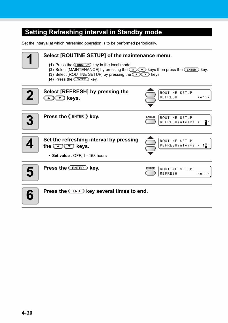
4-30
Setting Refreshing interval in Standby mode
Set the interval at which refreshing operation is to be performed periodically.
1 Select [ROUTINE SETUP] of the maintenance menu.
(1) Press the key in the local mode.(2) Select [MAINTENANCE] by pressing the keys then press the key.(3) Select [ROUTINE SETUP] by pressing the keys.(4) Press the key.
2 Select [REFRESH] by pressing the keys.
3 Press the key.
4 Set the refreshing interval by pressing the keys.
• Set value : OFF, 1 - 168 hours
5 Press the key.
6 Press the key several times to end.
ROU T I N E S E T U PR E F R E S H < e n t >
ROU T I N E S E T U PR E F R E S H i n t e r v a l = 1 h
ROU T I N E S E T U PR E F R E S H i n t e r v a l = 1 0 h
ROU T I N E S E T U PR E F R E S H < e n t >

4-31
Setting Routine operations
4
Ro
utin
e Main
tenan
ce
Setting Pump tube washing interval in Standby mode
Perform the pump tube washing periodically to prevent ink from clogging due to the coagulation of ink, which occurs within the tube.
1 Select [ROUTINE SETUP] of the maintenance menu.
(1) Press the key in the local mode.(2) Select [MAINTENANCE] by pressing the keys then press the key.(3) Select [ROUTINE SETUP] by pressing the keys.(4) Press the key.
2 Select [PUMP TUBE WASH] by press-ing the keys.
3 Press the key.
4 Set the tube washing interval by press-ing the keys.
• Set value : OFF, 1 - 168 hours
5 Press the key.
6 Press the key several times to end.
• This function is operable only under the condition that the machine is left in the following dis-plays.
• When the cleaning solution has not been filled in the machine, the right display is displayed at the step 5. Fill the cleaning solution ( P.4-8) then redo the operations from the step 1.
< L OC A L . 1 > [ # 0 1 ] * R EMO T E . 1 * [ # 0 1 ]0 . 0 0 m
LOCAL mode REMOTE mode
ROU T I N E S E T U PP UMP T U B E WA S H < e n t >
ROU T I N E S E T U PWA S H I N T E R V A L = 1 h
ROU T I N E S E T U PWA S H I N T E R V A L = 4 h
ROU T I N E S E T U PP UMP T U B E WA S H < e n t >
* * Wa s h i n g L i q u i d * *

4-32
Setting Cleaning interval in Standby mode
This function is to be executed instead of TUBE WASH after the cleaning solution has been used up.Set the cleaning type and the intervals at which cleaning operation is to be performed.
1 Select [ROUTINE SETUP] of the maintenance menu.
(1) Press the key in the local mode.(2) Select [MAINTENANCE] by pressing the keys then press the key.(3) Select [ROUTINE SETUP] by pressing the keys.(4) Press the key.
2 Select [CLEANING] by pressing the keys.
3 Press the key.
4 Set the cleaning interval by pressing the keys.
• Set valueÅFOFF, 1 - 168 hours
5 Press the key.
• The selection display of the cleaning type is dis-played.
6 Select the cleaning type by pressing the keys.
• Set value : NORMAL, SOFT, HARD
7 Press the key.
• This function does not operate when the error message relating to ink, such as [NEAR END] or [INK END], is displayed.
• While this function is being executed, the display indicates the progress of head cleaning and no key operation is available.(P.2-24 "Head Cleaning")
• This function operates only when the machine is left with the display as shown below:
< L OC A L . 1 > [ # 0 1 ] * R EMO T E . 1 * [ # 0 1 ]0 . 0 0 m
LOCAL mode REMOTE mode
ROU T I N E S E T U PC L E A N I NG < e n t >
ROU T I N E S E T U PC L E A N . I N T E R V A L = 1 h
ROU T I N E S E T U PC L E A N . I N T E R V A L = 4 h
ROU T I N E S E T U PC L E A N . T Y P E : NORMA L
ROU T I N E S E T U PC L E A N . T Y P E : SO F T
ROU T I N E S E T U PC L E A N . I N T E R V A L = 4 h

Setting Routine operations
4-33
4
Ro
utin
e Main
tenan
ce
8 Press the key several times to end.

4-34
Other maintenance functionsChanging the warning time of wiper replacement
The wiper is consumable. The heads are easily soiled in a dusty environment.The heads cannot be cleaned adequately with a curled or worn wiper.Setting the wiper level so that a warning for the wiper replacement period is indicated earlier than the stan-dard depending on the operating environment.
1 Select [WIPER LEVEL] of the maintenance menu.
(1) Press the key in the local mode.(2) Select [MAINTENANCE] by pressing the keys then press the key.(3) Select [WIPER LEVEL] by pressing the keys.
2 Press the key.
3 Set the wiper level by pressing the keys.
• Set value : 1/10 - 10/10
4 Press the key.
5 Press the key several times to end.
10/10Displays the wiper replacement warning when wiping has been performed the standardnumber of times. (Initial value)
9/10Displays the wiper replacement warning when wiping has been performed nine tenths ofthe standard number of times.
8/10Displays the wiper replacement warning when wiping has been performed eight tenths ofthe standard number of times.
1/10Displays the wiper replacement warning when wiping has been performed one tenth ofthe standard number of times.
Normal wiper Deformed wiper
W I P E R L E V E LL E V E L : 1 0 / 1 0
W I P E R L E V E LL E V E L : 9 / 1 0
MA I N T E N A NC EW I P E R L E V E L < e n t >

4-35
Other maintenance functions
4
Ro
utin
e Main
tenan
ce
Setting the media remaining display
Set the media remaining amount display.
1 Select [MEDIA RESIDUAL] of the maintenance menu.
(1) Press the key in the local mode.(2) Select [MAINTENANCE] by pressing the keys then press the key.(3) Select [MEDIA RESIDUAL] by pressing the keys.(4) Press the key.
2 Select ON/OFF by pressing the keys.
3 Press the key.
4 Press the key several times to end.
When the media remaining amount display is turned to "ON"
The media remaining amount is displayed in the remote mode.(The print length is displayed when a leaf media is used.)
When the media remaining amount display is turned to "OFF"
The media remaining amount is not displayed in the remote mode.
• The media feed during printing or with any of the JOG keys is reflected on media remaining amount.
• Input the media length (initial value of remaining amount) when the roll media is detected.• The setting performed in this section is not effective unless the media detection is performed
after the setting.
ME D I A R E S I DU A LS E T U P : O F F
MA I N T E N A NC EME D I A R E S I DU A L < e n t >

4-36
Print the media remaining amount
You can print the current media remaining amount.
1 In the local mode, press the keys.
• It enters into the origin setting mode.
2 Set a light point of the LED pointer to the changing position by pressing the keys.
• Select the carriage and media, moving thepoint with the keys.
• When not changing the origin, proceed tothe Step 3 without pressing
, , and key.
• When pressing key here, the ori-gin will be changed and it will return to thelocal mode.
3 Press the key.
• When pressing , , and key, the screen will return to the Step 2screen.
• When pressing key, it will return to the local mode.
4 Press the key.
• Start printing of the media remaining amount.• When the printing completes, it will return to the local mode.
• Set [MEDIA RESIDUAL] to “ON”. ( P.4-35)• When changing the media, it is recommended to print the remaining amount to the currently
used media. If you print the media remaining amount in advance, for using the changed media, you can enter the correct value in the screen for entering media remaining amount after detecting the media ( P.2-12).
• When printing after changing the origin, the origin set here will be valid when printing data sub-sequently.
OR I G I N S E T U P0 . 0 - - - -
OR I G I N S E T U P0 . 0 0 . 0
Origin (Length)
Origin (Width)
ME D I A R E S I DU A L DR AW< E N T >

4-37
Other maintenance functions
4
Ro
utin
e Main
tenan
ce
White Ink Maintenance Function
If SS21 white ink is left unused for a while, the color may become uneven by clogging of the nozzle or set-tling of pigment.If the color does not improved by the head cleaning ( P.2-24), use this maintenance function. (This func-tion is valid when the firmware Ver.4.10 or later is installed and SS21 white ink is filled.)
White ink maintenance function has three levels of maintenance.Select the maintenance level depending on the condition.
1 Select [WHITE MAINTE.] of the maintenance menu.
(1) Press the key in the local mode.(2) Select [MAINTENANCE] by pressing the keys then press the key.(3) Select [WHITE MAINTE.] by pressing the keys.
2 Press the key.
3 Select the maintenance level by press-ing the key.
• Set value : LEVEL1 to LEVEL3• This describes the operation when LEVEL3 is set.
4 Press the key.
LEVEL1Performs maintenance in the following order:
(1)Performs the automatic nozzle cleaning function. *1
(2)Performs cleaning. *2
*1. The operation is the same as the CUSTODY WASH of ST. MAINTENANCE. (Leaving time: three minutes)*2. The operation equivalent of “Hard cleaning” of the head cleaning is performed on each color. ( P.2-24).
LEVEL2
Performs maintenance in the following order:
(1)Performs the automatic nozzle cleaning function. *1
(2)Fills the white ink.(3)Performs cleaning. *2
LEVEL3
Performs maintenance in the following order:
(1)Performs the automatic nozzle cleaning function.*1(2)Discharges the white ink remaining in the head or in the tube.(3)Fills the white ink.(4)Performs cleaning.*2
• According to the level changing from 1 to 3, the amount of consumption becomes more. Use Level 2 and 3 when the status is not improved even if you perform Level 1 maintenance.
• When the machine is left unused for a long time, it is recommended to perform LEVEL1 of this function about every other week.
• The other cautions of this function or the white ink are included in the pack of the cartridge. Read it carefully before use.
WH I T E MA I N T E .S E L E C T : L E V E L 1
WH I T E MA I N T E .S E L E C T : L E V E L 3
S H A K E WH I T E I N KC A R T R I DGE S : e n t

4-38
5 Slowly shake the removed white ink cartridge more than twenty times right and left.
• To prevent ink from leaking when you shake the cartridge, wear gloves and firmly coverthe A part of the upper surface of the cartridge and the B part of the bottom surface of thecartridge with paper towels. Then, shake it more than twenty times right and left so that inkflows inside the cartridge.
6 Set the white ink cartridge, and press the key.
• Nozzle cleaning starts.• The operation after nozzle cleaning varies depending
on the LEVEL set on the Step 3.• LEVEL1 : Go to the Step 10.
LEVEL2 : Go to the Step 9.LEVEL3 : Go to the Step 7.
7 Remove the white ink cartridge.
• When the white ink cartridge is removed, the whiteink remaining in the machine is discharged.
• After discharging, the screen shown on the rightappears.
8 Set the white ink cartridge.
9 White ink filling starts.
• Filling time of LEVEL2 is different from LEVEL3. (When LEVEL2 is selected, filling time becomes shorter.)
10 Perform cleaning.
• If you shake it too strong, the pack inside may be damaged and it may cause ink leakage. Therefore, perform this carefully.
• If the remaining amount of ink is less, ink in the cartridge cannot be beaten enough. Tilt the cartridge until it becomes vertical.
A part (the place to stick a needle)
B part (the slot on the bottom)
Cover with paper towel firmly and shake ink slowly
Repeat this
A part
L v . * > NO Z Z L E WA S H0 3 : 0 0
The remaining time
The selected maintenance level
L v . 3 > D I S CH A RGE0 1 : 3 0
S E T : I N K C A R T R I DGE_ W_W_ _ _ _
L v . 3 > F I L L I NG U P0 0 : 3 0
L v . 3 > C L E A N I NG0 2 : 0 0

4-39
Other maintenance functions
4
Ro
utin
e Main
tenan
ce
To use sublimation transfer ink with more stable quality
When you print with sublimation transfer ink after you have left this machine, color may change due to color material settling.By shaking the ink cartridge or performing ink filling periodically, the status will be improved. (Before per-forming ink filling, it is necessary to shake the ink cartridge.)In the firmware version 5.00 and later, when the time to shake the ink cartridge or to perform ink filling has come, a message (warning preventing color material settling) is displayed to inform you of it.
When the time to shake the ink cartridge has come (When you use MBIS, it is not displayed.)
When the time to perform ink filling
• This message is displayed when the machine is in the local mode or when you switch it from the remote mode to the local mode.This does not terminate printing or interfere with continue printing, however, as this is not displayed during remote mode, it is recommended to switch to the local mode by pressing the key between printings.
SHAKE I NK CARTR I DGE .: e n t
< LOCA L . 1 > [ # 0 1 ]WI DTH : * * * * mm
SHAKE I NK CARTR I DGE .: e n t
< LOCA L . 1 > [ # 0 1 ]WI DTH : * * * * mm
Ca r r y o u t a[ F I L L UP I NK ] . : e n t
When you use MBIS, this message is not displayed.

4-40
How to shake the ink cartridge
To prevent ink from leaking when you shake the cartridge, wear gloves and firmly cover the A part of the upper surface of the cartridge and the B part of the bottom surface of the cartridge with paper towels. Then, shake it more than twenty times right and left so that ink flows inside the cartridge.
Set the interval to display the warning message
Depending on the ambient temperature, set the interval to display the warning preventing color material settling.
1 Select [ROUTINE SETUP] of the maintenance menu.
(1) Press the key in LOCAL.(2) Press to select [MAINTENANCE] and press the key.(3) Press to select [ROUTINE SETUP].(4) Press the key.
2 Press the key to select [Sub-INK WARNING].
• If you shake it too strong, the pack inside may be damaged and it may cause ink leakage. Therefore, perform this carefully.
• If the remaining amount of ink is less, ink in the cartridge cannot be beaten enough. Tilt the cartridge until it becomes vertical.
• If you shake the ink cartridge too strong, it may damage the inside pack and it may cause ink leakage. Be careful about it.
• When the cartridge is new, shake it before taking it out of bag.• When the cartridge is in-use, be sure to wear the gloves, press waste close to the inserted
side and shake it.• If the remaining amount of ink is less, tilt it until it becomes vertical, as you cannot shake it
enough in some cases.
• When you use MBIS, do not shake the eco case and the intermediate cartridge.• Do not insert and pull out the intermediate cartridge as much as possible. It may cause ink
leakage.
• When you use sublimation transfer ink Sb52 or Sb53, the display interval of the message is set to 72 hours in the initial condition.
• When you use sublimation transfer ink Sb51 or Sb60, this function is disabled (OFF) in the initial condition.
A part (the place to stick a needle)
B part (the slot on the bottom)
Cover with paper towel firmly and shake ink slowly
Repeat this
A part
ROU T I N E S E T U PS u b - I N K WA RN I NG < e n t >
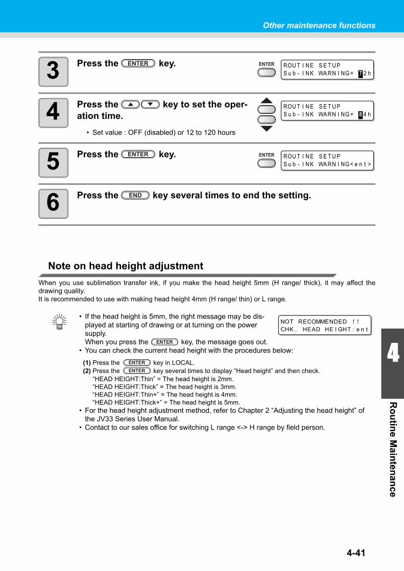
4-41
Other maintenance functions
4
Ro
utin
e Main
tenan
ce
3 Press the key.
4 Press the key to set the oper-ation time.
• Set value : OFF (disabled) or 12 to 120 hours
5 Press the key.
6 Press the key several times to end the setting.
Note on head height adjustment
When you use sublimation transfer ink, if you make the head height 5mm (H range/ thick), it may affect thedrawing quality.It is recommended to use with making head height 4mm (H range/ thin) or L range.
• If the head height is 5mm, the right message may be dis-played at starting of drawing or at turning on the power supply.When you press the key, the message goes out.
• You can check the current head height with the procedures below:
(1) Press the key in LOCAL.(2) Press the key several times to display “Head height” and then check.
“HEAD HEIGHT:Thin” = The head height is 2mm. “HEAD HEIGHT:Thick” = The head height is 3mm. “HEAD HEIGHT:Thin+” = The head height is 4mm. “HEAD HEIGHT:Thick+” = The head height is 5mm.
• For the head height adjustment method, refer to Chapter 2 “Adjusting the head height” of the JV33 Series User Manual.
• Contact to our sales office for switching L range <-> H range by field person.
ROU T I N E S E T U PS u b - I N K WA RN I NG = 7 2 h
ROU T I N E S E T U PS u b - I N K WA RN I NG = 8 4 h
ROU T I N E S E T U PS u b - I N K WA RN I NG < e n t >
NOT RECOMMENDED ! !CHK . HEAD HE I GHT : e n t

4-42
If Waste ink tank confirming message is displayed
Waste ink which was used for cleaning the heads and other parts, gathers in the waste ink tank. Upon the machine, the ink discharging amount is counted by accumulated counting then a message for suggesting the check is displayed when it reaches a certain amount.
If message is displayed when Ink filling or the like is executed
A message for suggesting to check the waste ink tank is displayed depending on the condition of the waste ink tank when the function such as ink filling, head cleaning, pump tube washing or the like is carried out.
When the waste ink tank is "Near-full"
The right message is displayed.
1 Check the condition of the waste ink tank.
When the waste ink tank is almost full(1) Replace the waste ink tank. ( P.4-44)(2) Select “Exchange” by pressing the key. (The ink discharging amount is reset.)
When the waste ink tank has room(1) Select “Continue” by pressing the key. (The ink discharging amount is not reset.)• In this case, the message of P.4-43 "Check message in Local mode" is displayed when it
returns to the local mode.
When the waste ink tank is full
The right message is displayed.
1 Replace the waste ink tank ( P.4-44) then press the key.
• The ink discharging amount is reset.
• Be sure to replace the waste ink tank ( P.4-44) if "Exchange" is selected by the operations above when the waste ink tank is "Near-full" or "Full". Waste ink may overflow the tank before the check message is displayed if the tank is not replaced and continuously used.
• Waste ink, which is discharged when [NOZZLE WASH], [PUMP TUBE WASH] and [CUS-TODY WASH] of [ST.MAINTENANCE] are performed, is not counted upon the machine. Be sure to check the condition of waste ink tank before or after the operations.
* C h e c k w a s t e i n k *C o n t i n u e < > E x c h a n g e
* C h e c k w a s t e i n k *E x c h a n g e : e n t

4-43
Other maintenance functions
4
Ro
utin
e Main
tenan
ce
Check message in Local mode
The right message is displayed.
1 Check the waste ink tank, and then replace the waste ink tank ( P.4-44) if required.
When waste ink tank check message is not needed
The waste ink tank check message can be set not to be displayed.
1 Select [Waste Ink Warning] of the machine setup menu.
(1) Press the key in the local mode.(2) Select [MACHINE SETUP] by pressing the keys then press the key.(3) Select [Waste Ink Warning] by pressing the keys.(4) Press the key.
2 Select "OFF " by pressing the keys.
3 Press the key.
4 Press the key several times to end.
• The check message is not displayed when the waste ink tank warning is set to "OFF". Be sure to check the ink remaining amount within the waste ink tank visually.
< L OC A L . 1 > [ # 0 1 ]C h e c k w a s t e i n k <MN T >
Wa s t e I n k Wa r n i n gS E T U P : O F F
MA CH I N E S E T U PWa s t e I n k Wa r n i n g < e n t >

4-44
Replacing waste ink tank
When the right message is displayed, check the waste ink tank immediately, and then replace it according to the condition.
1 Remove the waste ink tank guard.
(1) Lift the waste ink tank guard then release a lock.(2) Open the waste ink tank guard frontward.
2 Pull it frontward to remove by holding the waste ink tank handle.
• Put a cap on the waste ink tank removed.
3 Replace the waste ink tank.
(1) Prepare a new waste ink tank (SPC-0117).(2) Insert the waste ink tank by holding a handle of
the tank.
< L OC A L . 1 > [ # 0 1 ]C h e c k w a s t e i n k <MN T >
Waste ink tank guard
Lift then pull it frontward.
Cap
Waste ink
New waste ink tank
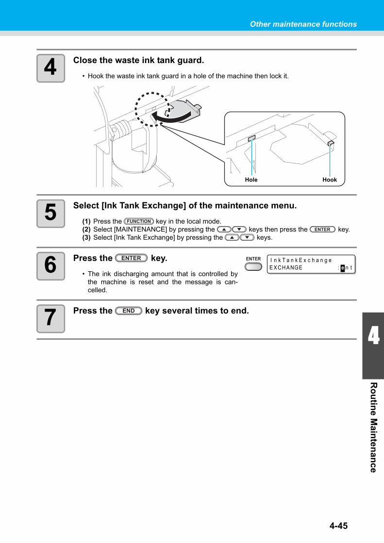
4-45
Other maintenance functions
4
Ro
utin
e Main
tenan
ce
4 Close the waste ink tank guard.
• Hook the waste ink tank guard in a hole of the machine then lock it.
5 Select [Ink Tank Exchange] of the maintenance menu.
(1) Press the key in the local mode.(2) Select [MAINTENANCE] by pressing the keys then press the key.(3) Select [Ink Tank Exchange] by pressing the keys.
6 Press the key.
• The ink discharging amount that is controlled bythe machine is reset and the message is can-celled.
7 Press the key several times to end.
Hole Hook
I n k T a n k E x c h a n g eE X CH A NGE : e n t

Other maintenance functions
4-46
Changing the ink
Ink type or the color used can be changed.
• To change the ink set such as changing from “4-color model“ to “6-color model”” or “8-color model”, the machine must be worked by our service engineer. Contact our service office or the distributor in your region.
Change the ink type Change the ink color
To change the ink type used such as changing fromES3 ink to SS21 ink, work as follows.
To change the ink color used such as changing from “6-colors” to “6-colors + white” of SS21 ink, work as fol-lows.
• Note for changing ink typeChangeable ink type is limited by the type of ink used. See the table on the right.
• Note for changing ink colorTo replace white ink of SS21 from “SS21W” to “SS21W-2”, follow the exhibit “Before using new White Ink (SS21-W2)” (D201848).
• When washing, use a special cleaning solution cartridge (sold separately).Wash with the proper cleaning solution cartridge for the used ink type.
“Discharge” the remaining ink inthe machine, and “Wash” the heador the tube.
See P.4-19 "DISCHARGE & WASH".
Fill ink. See P.4-21 "Initial ink fill up".
Ink type to be changed
PIG Sublimation dye ink SS21/ES3
Ink type used
PIGChangeable Contact our service office or the distributor in your
region.Sublimation dye ink
SS21ES3 Not changeableChangeable
(However, when you wish to change to silver ink or white ink of ES3, the work by our service staff is required.)
Ink Type Cleaning Solution Type
Solvent ink MILD SOLVENT Cleaning Solution Cartridge (SPC-0294)
Aqueous pigment inkAqueous cleaning solution cartridge (SPC-0259)
Sublimation dye ink

4-47
4
Ro
utin
e Main
tenan
ceReplacing the cutter blade
The cutter blade is consumable. When the cutter blade gets dull, replace it with a new one (SPA-0107).
1 Press the key then press the key.
• The carriage moves onto the platen.
2 Open the front cover.
3 Replace the cutter unit by the carriage.
(1) Loosen a screw of the cutter unit.(2) Remove the cutter unit.(3) Mount a new cutter unit.(4) Fasten the screw of the cutter unit to secure the cutter unit.
• The blade is sharp. Be careful not to hurt yourself or anyone else.• Keep the cutter blades away from the reach of children. Be sure to dispose of the worn-out
cutter blades according to the applicable national and local laws and regulations.
• When replacing the cutter blade, it is recommended to place a sheet of paper under the cutter blade. This will help pick up the cutter blade if it drops.
Front cover
Screw
Cutter unit

Replacing the cutter blade
4-48
4 Close the front cover.
5 Press the key.
• The machine returns to LOCAL mode.

This section describes the corrective measures to be taken for aphenomenon suspected to be trouble and the procedures to clearthe error number displayed on the LCD.
Troubleshooting .......................................................... 5-2Power does not turn on ......................................................5-2The machine does not start printing ..................................5-2Media get jammed / media is soiled ..................................5-3[HEAT] or [CONSTANT] LED does not light up .................5-3Image quality is poor ..........................................................5-4Nozzle is clogged ...............................................................5-4Ink cartridge warning appears ...........................................5-5
Warning / Error Messages .......................................... 5-6Warning messages ............................................................5-6Error messages .................................................................5-9
CHAPTER 5
Troubleshooting

5-2
TroubleshootingTake appropriate actions as described below before taking the trouble as a failure.If still the problem is not solved after troubleshooting, contact your dealer or an office of MIMAKI.
Power does not turn on
In most cases, this is due to improper connection of the power cable for the machine or computer. Check that the power cable is connected properly.
The machine does not start printing
This occurs when the data is not being transmitted to the machine properly.It can also occur when the printing function does not work properly or the media is not set correctly.
Has the power cable been connected between the machine and a power plug socket ?
Securely connect the power cable.
Is the main switch ON ? Turn on the main switch. ( P.2-4)
Is the power switch located on the front of machine "ON" ?
Turn on the power switch on the front of the machine.
Is the correct interface cable used ? Use the cable exclusive for the device.
Is the interface cable properly con-nected ?
Securely connect the interface cable.
Yes
Is the message on the display indicat-ing that ink has run out ?
Replace the ink cartridge with a new one.
No
No
No
No
No
Yes

5-3
Troubleshooting
5
Trou
blesh
oo
ting
Media get jammed / media is soiled
Media jamming or stained media is considered to be due to the use of an unsuitable media or improper set-ting of media.
[HEAT] or [CONSTANT] LED does not light up
Check the basic operation.
Is a recommended media used ? Use recommended media.
Is the media not curled or bent ends ?Avoid using any media with curls or bent ends.
Yes
Is the media hanging down along the platen ?
Use a take-up device or re-load the media on the machine. (Except Type B)( P.2-6 , P.2-13)
Is the power to the machine ON ?Turn on the power to the machine. ( P.2-4)
Yes
Is the heater temperature setting effec-tive ?
Set the heater temperature. ( P.3-8)
No
No
No
No
No
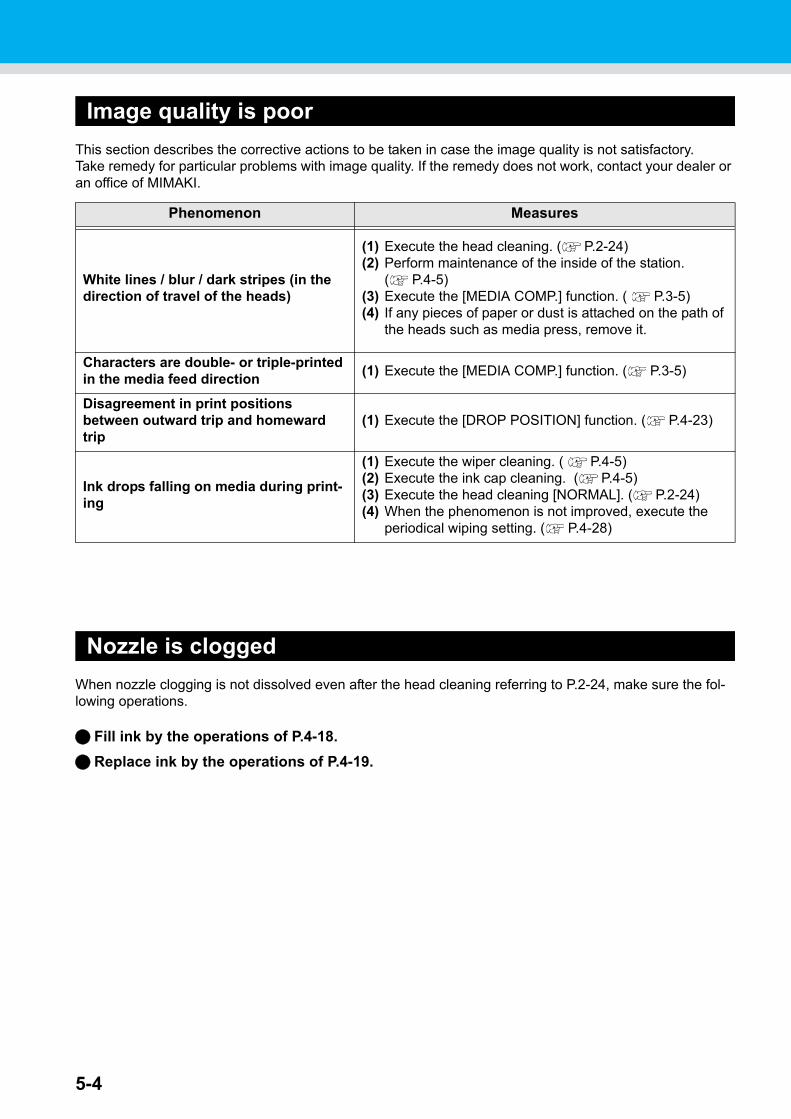
5-4
Image quality is poor
This section describes the corrective actions to be taken in case the image quality is not satisfactory.Take remedy for particular problems with image quality. If the remedy does not work, contact your dealer or an office of MIMAKI.
Nozzle is clogged
When nozzle clogging is not dissolved even after the head cleaning referring to P.2-24, make sure the fol-lowing operations.
Fill ink by the operations of P.4-18.
Replace ink by the operations of P.4-19.
Phenomenon Measures
White lines / blur / dark stripes (in the direction of travel of the heads)
(1) Execute the head cleaning. ( P.2-24)(2) Perform maintenance of the inside of the station.
( P.4-5)(3) Execute the [MEDIA COMP.] function. ( P.3-5)(4) If any pieces of paper or dust is attached on the path of
the heads such as media press, remove it.
Characters are double- or triple-printed in the media feed direction
(1) Execute the [MEDIA COMP.] function. ( P.3-5)
Disagreement in print positions between outward trip and homeward trip
(1) Execute the [DROP POSITION] function. ( P.4-23)
Ink drops falling on media during print-ing
(1) Execute the wiper cleaning. ( P.4-5)(2) Execute the ink cap cleaning. ( P.4-5)(3) Execute the head cleaning [NORMAL]. ( P.2-24)(4) When the phenomenon is not improved, execute the
periodical wiping setting. ( P.4-28)

Troubleshooting
5-5
5
Trou
blesh
oo
ting
Ink cartridge warning appears
If an ink cartridge trouble is detected, a warning message appears and none of printing, cleaning and all the other operations that use ink is available.In this case, replace the ink cartridge in question immediately.
Displaying the description of ink cartridge trouble
The contents of cartridge error are confirmable by the following operations. ( P.5-7)
1 Press the key in the local mode.
2 Press the key.
• When two or more cartridge troubles occur, warnings can be displayed in turn by pressingthe or key.
• Press the key or key to return to the display of the remaining amount ofink.
• Once cartridge trouble is displayed, do not leave the ink cartridge without replacing it for a long time; otherwise, the machine will lose the nozzle clogging prevention function.If nozzles are clogged, the machine must be repaired by MIMAKI's service engineer.
E S 3 MMCC Y Y K KR EMA I N 3 4 5 6 7 8 9 9
NON - OR I G I N A L I N K- - - C - - - -

5-6
Warning / Error MessagesIf some trouble occurs, the buzzer sounds and the display shows a corresponding error message.Take an appropriate remedy for the displayed error.
Warning messages
Message Cause Solution
The front cover or the maintenance cover is opened.
Check the front cover and maintenance covers.If the same error message appears again even after closing all the covers, contact your local distributor to call for service.
A media has not been set. Set media.
The battery life end of the internal clock is detected.
Contact your local distributor to call for service.
Time to replace the wiper in the capping station with a new one has come.(The wiping count has reached the specified value.)
Replace the wiper with a new one. ( P.4-7)
The nozzle recovery cannot be expected because the machine has been left standing for a prolonged period of time.
Perform test printing then check nozzle clogging.In the case of nozzle clogging observed, perform cleaning. ( P.2-24)In the case of significant nozzle clogging observed, perform the operations of P.4-10"Washing of Head nozzle".
A heater is disconnected.(This example shows that pre-heater is disconnected.)
Contact your local distributor to call for service.
The thermistor of a heater is defec-tive.(This example shows that the thermistor of pre-heater is defec-tive.)
Ink for one supply path has been nearly used up.
Replace the cartridge for the supply path corresponding to the indicated color.You can print without replacing the car-tridge (until INK END is displayed).However, the machine returns to local mode every completion of printing one file.
Ink for one supply path has been completely used up.
Replace the cartridge for the supply path corresponding to the indicated color.
Ink cannot be supplied due to the cartridge per one supply path.
Check the cartridge for the supply path corresponding to the indicated color.
C l o s e a c o v e r .
* * NO ME D I A * *
! E X CH A NGE B A T T E R Y
< L OC A L . 1 > [ # 0 1 ]R e p l a c e a W I P E R <MN T >
< L OC A L . 1 > [ # 0 1 ]! D o T E S T DR AW
P R E P R T POS TB R E A K * * ° C * * ° C
P R E P R T POS TT H E RM * * ° C * * ° C
< L OC A L . 1 > [ # 0 1 ]N E A R E ND MMCC - - - -
* R EMO T E . 1 * [ # 0 1 ]N E A R E ND MMCC - - - -
< L OC A L . 1 > [ # 0 1 ]I N K E ND - - - - Y Y K K
* R EMO T E . 1 * [ # 0 1 ]I N K E ND - - - - Y Y K K
< L OC A L . 1 > ! C A R[ # 0 1 ]
* R EMO T E . 1 * ! C A R[ # 0 1 ]

5-7
Warning / Error Messages
5
Trou
blesh
oo
ting
Message Cause Solution
Ink near end was detected right after the cartridge with much remaining amount of ink has been inserted.
Pull out the inserted cartridge and insert it again. If the message will be displayed again, contact a distributor in your district or our office to call for service.
There is a problem with installed ink cartridges.(In the case of overlapping with other warnings, the display turns to "< LOCAL.1> !CAR/WASH" and [#**] is erased. )
Check the content of the warning details in the guidance function.
There is a problem with the installed cleaning solution cartridge.(In the case of overlapping with other warnings, the display turns to "< LOCAL.1> !CAR/WASH" and [#**] is erased. )
Check that the cleaning solution cartridge has been set properly.
The ink of the ink cartridge has been nearly used up.
Replace the cartridge generating the warning with a new one.
The ink of the ink cartridge has been completely used up.
Replace the cartridge generating the warning with a new one.
The ink cartridge is not MIMAKI genuine.
Replace the cartridge generating the warning with a MIMAKI genuine.
The IC chip of the ink cartridge can-not be read normally.
Remove the cartridge generating the warning once and install it again.If the same warning message still appears, contact your local distributor to call for service.
The ink of the ink cartridge is differ-ent in type from the ink currently supplied.
Check the ink type of the cartridge gener-ating the warning.
The ink of the ink cartridge is differ-ent in color from the ink currently supplied.
Check the ink color of the cartridge gener-ating the warning.
There is trouble with an installed ink cartridge.
Check the cartridge generating the warn-ing.
An ink cartridge has not been installed in the slot.
Install an appropriate cartridge in the slot generating the warning.
The specified expiration date of an ink cartridge has passed.
Replace the cartridge generating the warning with a new one.The cartridge may be used until one month passes after the specified expira-tion date.
The expiration date of an ink car-tridge has passed (one month has passed after the specified expiration date).
The red LED blinks. Replace the cartridge generating the warning with a new one.The cartridge may be used until two months pass after the specified expiration date.
< L OC A L . 1 > [ # 0 1 ]R E I N S E R T C A R T R I DGE
< L OC A L . 1 > ! C A R[ # 0 1 ]
* R EMO T E . 1 * ! C A R[ # 0 1 ]
< L OC A L . 1 > ! WA S H[ # 0 1 ]
* R EMO T E . 1 * ! WA S H[ # 0 1 ]
I N K N E A R E NDMMCC - - - -
I N K E ND- - - - Y Y K K
NON - OR I G I N A L I N K- - - - Y Y K K
WRONG I N K I C- - - - Y Y K K
K i n d o f I N K- - - - - - - -
C o l o r o f I N K- - - - - - - -
WRONG C A R T R I DGE- - - - - - - -
NO C A R T R I DGE- - - - - - - -
E x p i r a t i o n- - - - - - - -
E x p i r a t i o n : 1 MON T H- - - - - - - -
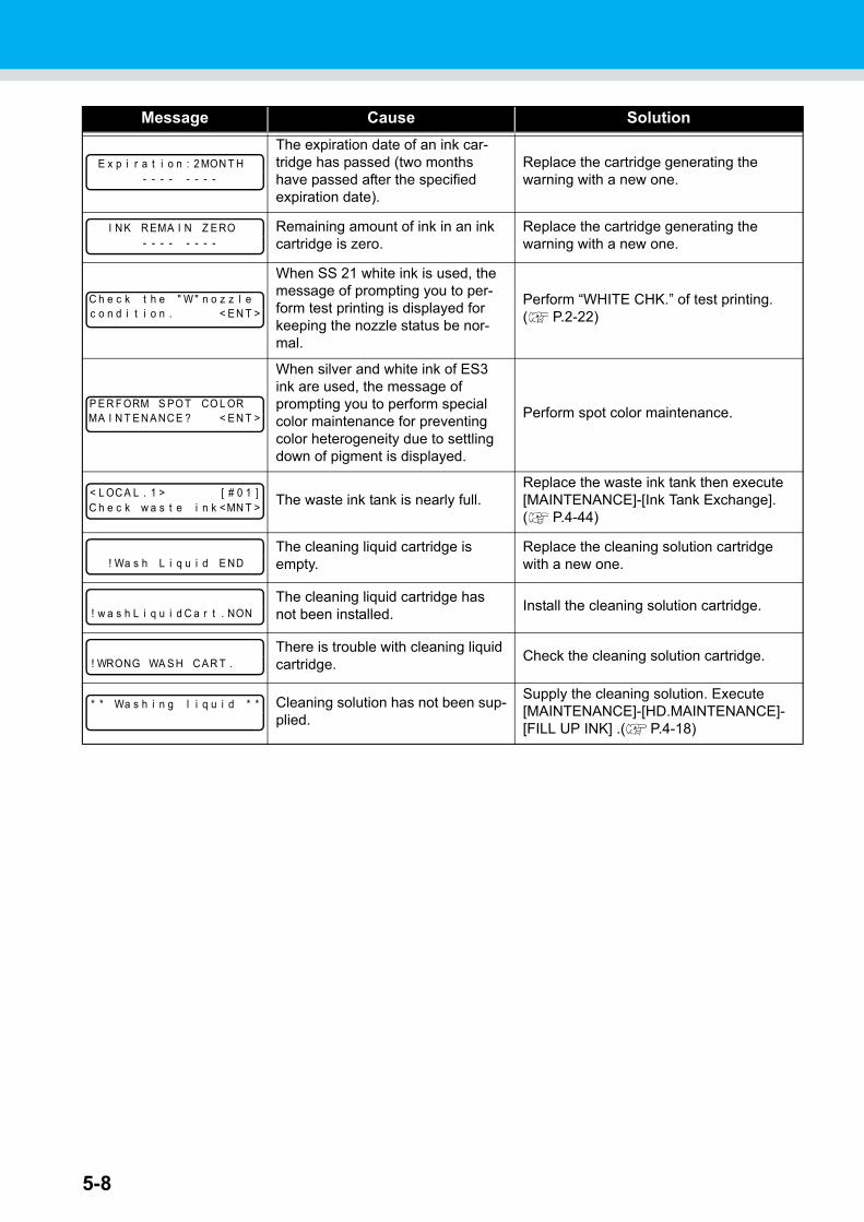
5-8
Message Cause Solution
The expiration date of an ink car-tridge has passed (two months have passed after the specified expiration date).
Replace the cartridge generating the warning with a new one.
Remaining amount of ink in an ink cartridge is zero.
Replace the cartridge generating the warning with a new one.
When SS 21 white ink is used, the message of prompting you to per-form test printing is displayed for keeping the nozzle status be nor-mal.
Perform “WHITE CHK.” of test printing. ( P.2-22)
When silver and white ink of ES3 ink are used, the message of prompting you to perform special color maintenance for preventing color heterogeneity due to settling down of pigment is displayed.
Perform spot color maintenance.
The waste ink tank is nearly full.Replace the waste ink tank then execute [MAINTENANCE]-[Ink Tank Exchange].( P.4-44)
The cleaning liquid cartridge is empty.
Replace the cleaning solution cartridge with a new one.
The cleaning liquid cartridge has not been installed.
Install the cleaning solution cartridge.
There is trouble with cleaning liquid cartridge.
Check the cleaning solution cartridge.
Cleaning solution has not been sup-plied.
Supply the cleaning solution. Execute [MAINTENANCE]-[HD.MAINTENANCE]-[FILL UP INK] .( P.4-18)
E x p i r a t i o n : 2 MON T H- - - - - - - -
I N K R EMA I N Z E RO- - - - - - - -
C h e c k t h e " W " n o z z l ec o n d i t i o n . < E N T >
P E R F ORM S PO T CO L ORMA I N T E N A NC E ? < E N T >
< L OC A L . 1 > [ # 0 1 ]C h e c k w a s t e i n k <MN T >
! Wa s h L i q u i d E ND
! w a s h L i q u i d C a r t . NON
! WRONG WA S H C A R T .
* * Wa s h i n g l i q u i d * *

5-9
Warning / Error Messages
5
Trou
blesh
oo
ting
Error messages
When an error message is displayed, eliminate the error according to the chart below.If the same error message appears again, contact your dealer or an office of MIMAKI to call for service.
Message Cause Solution
An error occurred in the circuit board system. (ROM)
Turn off the power to the machine and turn it on after a while.If the same error message appears again, contact your local distributor to call for ser-vice.
An error occurred in the circuit board system. (RAM)
An error occurred in the circuit board system. (POWER +5V)
An error occurred in the circuit board system. (POWER +24V)
An error occurred in the circuit board system. (POWER +42V)
An error occurred in the circuit board system. (F-ROM)
An error occurred in the circuit board system. (SD-RAM)
An error in heads was detected. (Abnormal temperature was detected.)
An error in heads was detected. (Abnormal voltage was detected.)
An error occurred in the linear encoder. (Counting was unable. )
An error occurred in the linear encoder. (Error in the mounting direction.)
An error occurred in the linear encoder. (Read-out count error)
An error occurred in the circuit board system.(FPGA PDC)
An error occurred in the circuit board system.(FPGA HDC)
The machine received some data other than command data.
Securely connect the interface cable in position.Use an interface cable conforming to the specifications.
* * * * * E RROR 0 1 * * * * *MA I N ROM
* * * * * E RROR 0 2 * * * * *MA I N R AM
* * * * * E RROR 0 3 * * * * *POWE R + 5 V
* * * * * E RROR 0 3 * * * * *POWE R + 2 4 V
* * * * * E RROR 0 3 * * * * *POWE R + 4 2 V
* * * * * E RROR 0 4 * * * * *F - ROM
* * * * * E RROR 0 6 * * * * *S D - R AM
* * * * * E RROR 0 7 * * * * *H E A D ( - - - - )
* * * * * E RROR 0 7 * * * * *VO L T AGE ( - - - - )
* * * * * E RROR 0 8 * * * * *L i n e a r E NCOD E R : S E N SOR
* * * * * E RROR 0 8 * * * * *L i n e a r E NCOD E R : D I R .
* * * * * E RROR 0 8 * * * * *L i n e a r E NCOD E R : COUN T
* * * * * E RROR 0 9 * * * * *F PGA E RROR
* * * * * E RROR 0 9 * * * * *HDC E RROR ( - - - - )
* * * * * E RROR 1 0 * * * * *COMMA ND E RROR

5-10
Message Cause Solution
Any parameter outside the range of acceptable numeric values was received.
Turn off the main power to the machine and turn it on after a while.If the same error message appears again, contact your local distributor to call for ser-vice.
The received data does not follow the command system set by the machine.
Transmit data that is compatible with the command system supported by this machine.
An error occurred in communication between the host computer and the interface board for USB2.0 connec-tion.(Full-Speed mode connection)
Check that the host PC supports the USB2.0 interface.(Communication can be resumed without changing any setting. However, it is rec-ommend to use the connection in High-Speed mode.)
An error occurred in communication between the host computer and the interface board for USB2.0 connec-tion.
Check that the cable is securely con-nected to the host computer and interface board.Also, check to see if any error has occurred on the host computer.
An error occurred in communication between the host computer and the interface board for USB2.0 connec-tion.
An error occurred in communication between the host computer and the interface board for USB2.0 connec-tion.
An error occurred in communication between the host computer and the machine for USB2.0 connection.
Improper operation was conducted on the operation panel.
Perform correct operations.
It is being tried to change settings for functions though there remains received data that has not yet been printed.
Print all the received data or execute the data clear function. Then, change settings.
An excessive load was applied to the X motor.
Turn off the main power to the machine and turn it on after a while.If the same error message appears again, contact your local distributor to call for ser-vice.
An excessive load was applied to the Y motor.
An error due to an excessive cur-rent of the X motor was detected.
An error due to an excessive cur-rent of the Y motor was detected.
An error occurred in the capping control. (Improper parameter adjustment value)
* * * * * E RROR 1 1 * * * * *P A R AME T E R E RROR
* * * * * E RROR 1 6 * * * * *MR L COMMA ND
* * * * * E RROR 2 5 * * * * *F U L L - S P E E D
* * * * * E RROR 2 5 * * * * *P A C K E T S I Z E OV E R
* * * * * E RROR 2 5 * * * * *U S B P RO T OCO L
* * * * * E RROR 2 5 * * * * *U S B E N V I RONME N T
* * * * * E RROR 2 5 * * * * *U S B D A T A
* * * * * E RROR 3 0 * * * * *C A N ‘ T OP E R A T E
* * * * * E RROR 3 4 * * * * *D A T A R EMA I N
* * * * * E RROR 4 0 * * * * *MO T OR A L A RM X
* * * * * E RROR 4 1 * * * * *MO T OR A L A RM Y
* * * * * E RROR 4 2 * * * * *X OV E R CURR E N T
* * * * * E RROR 4 3 * * * * *Y OV E R CURR E N T
* * * * * E RROR 4 5 * * * * *C A P P I NG : P A R AME T E R

5-11
Warning / Error Messages
5
Trou
blesh
oo
ting
Message Cause Solution
An error occurred in the wiper con-trol.
Turn off the main power to the machine and turn it on after a while.If the same error message appears again, contact your local distributor to call for ser-vice.
Paper could not be detected.The media set position or media itself is not proper.
If the same error message appears again even after setting the media properly, con-tact your local distributor to call for service.
The set position of the media is not proper. The media detection has not completed.
Set the media to the proper position again. ( P.2-8, P.2-14)
Y-origin could not be detected.
Turn off the main power to the machine and turn it on after a while.If the same error message appears again, contact your local distributor to call for ser-vice.
The room temperature is out of the usable temperature range (too low).
Adjust the room temperature of the instal-lation place. ( P.3-38)The room temperature is out of the
usable temperature range (too high).
There is a slot where no cartridge has been inserted.
Set a cartridge.
An error occurred on the head unit memory. Turn off the main power to the machine
and turn it on after a while.If the same error message appears again, contact your local distributor to call for ser-vice.
The head is not connected.An error occurred on the head slider board.The head is not MIMAKI genuine.
A SD-RAM of the size required for the machine has not been equipped.
Turn off the main power to the machine and turn it on after a while.If the same error message appears again, contact your local distributor to call for ser-vice.(When a usable SD-RAM is available, the machine can be started as is. However, a printing speed may be slow depending on resolution. )
An error is detected on the wave-form printed on the lower line of the display. Turn off the main power to the machine
and turn it on after a while.If the same error message appears again, contact your local distributor to call for ser-vice.
Model ID of main PCB is different.(XX is ID code.)
An abnormal temperature of the media heater was detected.
* * * * * E RROR 4 6 * * * * *W I P E R
* * * * * E RROR 5 0 * * * * *ME D I A W I D T H S E N SOR
* * * * * E RROR 5 0 * * * * *ME D I A S E T POS I T I ON L
* * * * * E RROR 5 0 * * * * *ME D I A S E T POS I T I ON R
* * * * * E RROR 5 1 * * * * *Y - OR I G I N
* * * * E RROR 1 2 0 * * * *ROOM T EMP L OW ( X X ° C )
* * * * E RROR 1 2 1 * * * *ROOM T EMP H I GH ( X X ° C )
* * * * E RROR 1 4 4 * * * *C A R T R I DGE S E T !
* * * * E RROR 2 0 0 * * * *H E A D MEMOR Y ( - - - - )
* * * * E RROR 2 0 2 * * * *D V E I C E CON S T RUC T I ON
* * * * E RROR 2 0 3 * * * *S DR AM S I Z E
* * * * E RROR 2 0 7 * * * *X X X X X X X X X X
* * * * E RROR 2 0 8 * * * *CH E C K MA I N P C B I D X X
* * * * E RROR 2 1 1 * * * *H e a t e r T EMP ( - - / - - / - - )

Warning / Error Messages
5-12
Message Cause Solution
An abnormal temperature of the head heater was detected.
Turn off the main power to the machine and turn it on after a while.If the same error message appears again, contact your local distributor to call for ser-vice.
The head heater is disconnected.
Trouble has occurred with the thermistor of the head heater.
An error was detected during scan-ning operation.
A system error occurred.
* * * * E RROR 2 1 1 * * * *H e a d WA RM . T EMP . ( - - - - )
* * * * E RROR 2 1 1 * * * *H e a d WA RM . B R E A K ( - - - - )
* * * * E RROR 2 1 1 * * * *H e a d WA RM . T H E RM ( - - - - )
* * * * E RROR 2 5 0 * * * *Y COORD I N A T E S
* * * * E RROR 2 5 1 * * * *S Y S T EM E RROR

This section attaches a list of the specifications and a list of thefunctions of this printer.
Machine specifications ............................................... 6-2Ink specifications ........................................................ 6-4Sheet for inquiry .......................................................... 6-5Warning labels ............................................................. 6-6Function Flowchart ..................................................... 6-8
CHAPTER 6
Appendix

6-2
Machine specificationsItem JV33-130 JV33-160
Print headMethod Drop-on-demand piezoelectric print heads
Specification 1 head
Drawing mode (scan x feed)
720 x 540dpi540 or 720 x 720dpi540 x 900dpi540 or 720 x 1080dpi720 x 1440dpi1440 x 1440dpi
Usable inks
Dedicated solvent ink.
Either ES3 ink or SS21 ink
Dedicated aqueous ink.
Either one of aqueous pigment ink or sublimation dye inkAqueous pigment ink : 4 colors (Y,M,C,K)
6 colors (Y,M,C,K,Lc,Lm)Eco-PA1 ink : 4 colors (Y,M,C,K)
6 colors (Y,M,C,K,Lc,Lm)7 colors (Y,M,C,K,Lc,Lm,Lk)
Sublimation dye ink (Sb51/Sb53/Sb60): 4 colors (Y,M,Bl,K)
6 colors (Y,M,Bl,K,LBl,Lm)Sublimation dye ink (Sb52) : 4 colors (Y,M,Bl,K)
6 colors (Y,M,Bl,K,LBl,Lm)6 colors (Y,M,BB,K,LBB,Lm)
Ink supplySupplying from ink cartridges through tubes.Ink cartridge replacement type :Only at 4 colors: Supplying by Toggle switchover with 2 cartridges/color
Capacity of ink cartridge
Dedicated solvent ink
When eight colors are used:White and silver One 220-cc cartridge for each colorOther colors One 440-cc cartridge for each color
6-color set of cartridges :440cc 1 cartridge for each color, 440 cc/1 color (2 cartridges, 880cc only for magenta and cyanogen)
6 colors + white color installed:White 2x220cc cartridges, 440cc / 1 colorOther colors 1x440cc cartridge for each color, 440cc / 1 color
4-color set installed :440cc 2 cartridges for each color, 880cc/1 color
Dedicated aqueous ink
6-color set of cartridges :440cc or 220cc 1 cartridge for each color, 440cc/1 color or 220cc/1 color (2 cartridges, 880cc or 440cc only for magenta and cyanogen)
4-color set installed :440cc or 220cc 2 cartridges for each color, 880cc/1 color or 440cc/1 color
Media type
Dedicated solvent ink
Tarpaulin, FF, PVC
Dedicated aqueous ink
Photo-paper , Synthetic paper , Duplex paper
Max. printing width 1361mm 1610mm
• For K of sublimation dye ink (Sb52), choose one from the following four types.
K : Deep BlackRK : Reddish Black (high density)NK : Normal Black
(Lower density than K. (about the same as Sb51))NRK: Normal Reddish Black
(Lower density than RK. (slightly higher density than Sb51))

6-3
Machine specifications
6
Ap
pen
dix
Roll Media size
Maximum 1371mm 1620mm
Minimum 210mm
Thickness 1.0 mm or less
Roll outside diame-ter
180mm or less
Roll weight *1 25kg or less
Roll inside diameter 3 or 2 inches
Printing surface Side facing outward
Roll end treatmentThe roll end is gently fixed to the core with weak-adhesive tape or weak glue for easy removal.
Leaf media sizeMaximum 1371mm 1620mm
Minimum 210mm
MarginLeaf media
Left end and right end : 15 mm (Default)Front : 40.0 mm Rear : 98.5 mm
Roll mediaLeft end and right end : 15 mm (Default)Front : 40.0 mm Rear : 0.0 mm
Distance accu-racy
Absolute accuracy Whichever the larger one of ± 0.3 mm or ± 0.3 % of the designated
Reproducibility Whichever the larger one of ± 0.2 mm or ± 0.1 % of the designated
Perpendicularity ± 0.5 mm / 1000 mm
Media skew 5 mm or less / 10 m variable
Head height adjustment 2.0mm / 3.0mm (from the platen surface) 2 levels adjustable
Cutting of mediaCutting of Y direction by the head cutter, Cutting accuracy (steps) : 0.5 mm or less.
Media deliveryTake-up device supplied as a standard accessory (switching possible between face in and face out).
Waste ink tank Bottle type (2,000 cc)
Interface USB 2.0
Command MRL- III
Noise
during standby Less than 58 dB (FAST-A, Front & Rear & Left & Right 1 m)
during continuous printing
Less than 65 dB
during discontinu-ous printing
Less than 70 dB
Safety StandardVCCI-Class A, FCC-Class A, UL 60950, CE Marking (EMC,Low Voltage Directive), CB Report, RoHS
PowerAC100 - 120 ± 10% , AC220 - 240 ± 10% , 50/60Hz ± 1Hz , 15A or less
Power consumption *2 1333 W or less
Recomended Environment
Available temp. 20 °C to 35 °C
Humidity 35 to 65% Rh (No condensation)
Guaranteed temp. 20 °C to 25 °C
Temperature change ± 10 °C / h or less
Dust Equivalent to normal office level
Weight 145 kg 160 kg
Outside dimen-sions
Width 2289 mm 2538 mm
Depth 739 mm
Height 1424 mm
*1. Without deflection of the roll when it is retained at both ends.*2. Main unit and heater included.
Item JV33-130 JV33-160

6-4
Ink specificationsItem When solvent ink is used When aqueous-color ink is used
Supply Dedicated solvent ink cartridges
Dedicated aqueous pigment ink car-tridgeDedicated sublimation dye ink cartridge Eco-PA1 ink
Color
Black ink cartridgeCyan ink cartridgeMagenta ink cartridgeYellow ink cartridgeLight cyan ink cartridgeLight magenta ink cartridgeWhite ink cartridge *1
Silver ink cartridge *2
*1. When SS21W-2 (SPC-0504-W) ink cartridge is used.When ES3 white ink (SPC-0433-W) ink cartridge is used.
*2. When ES3 silver ink (SPC-0433-Si) ink cartridge is used.
Black ink cartridgeCyan ink cartridge(Blue ink cartridge*3)Magenta ink cartridgeYellow ink cartridgeLight cyan ink cartridge(Light blue ink cartridge*3)Light magenta ink cartridgeReddish black ink cartridge *4
Normal black ink cartridge *4
Normal reddish black ink cartridge *4
Brilliant blue ink cartridge *4
Light brilliant blue ink cartridge *4
Light black ink cartridge *5
*3. When dedicated sublimation dye ink cartridge (Sb51/Sb53/Sb60) ink cartridge is used.*4. When dedicated sublimation dye ink cartridge (Sb52) ink cartridge is used.*5. When Eco-PA1 ink cartridge (Sb51) ink cartridge is used.
Ink capacity 220cc / 440cc per cartridge
Shelf life
• SS21 Ink1 year from the date of manufacture (at room temperature)
• ES3 InkTwo years from the date of manufacture (at room temperature)
Within three months after opening the package
• Aqueous pigment ink1 year from the date of manufacture (at room temperature)
• Sublimation dye ink1 year from the date of manufacture (at room temperature)
Storage tem-perature
Storage0 to 25°C (Average daily temperature)• Be sure to keep a vessel in the airtight
condition.
10 to 35°C (Average daily temperature)• Be sure to keep a vessel in the airtight
condition.• Be sure to keep a vessel in a dry, well-
ventilated, cool and dark location.
Transporta-tion
-20 to 60°C• Avoid the condition lower than -20 °C
and higher than 60 °C.
0 to 40°C• Avoid the condition lower than -0 °C
and higher than 40 °C.
Do not disassemble ink cartridges and do not refill them with ink. Ink could freeze if kept in a cold place for an extended period.
• When solvent ink is used, if the ink freezes, thaw it at room temperature (25°C) spending more than three hours before use.
• When aqueous ink is used, if the ink freezes, the quality is changed and the ink becomes unusable. Store the ink in an environment that will not freeze the ink.

6-5
6
Ap
pen
dix
Sheet for inquiryUse this sheet for troubles and abnormal functions of the machine.Fill in the following necessary items, and then fax the sheet to our sales office.
Company name
Person in charge
Telephone number
machine model
Operating OS
Machine information *1
*1. Refer to "Confirming Machine information" of "Convenient using" then fill in necessary information. ( P.3-48)
Error message
Contents of inquiry

6-6
Warning labelsWarning labels are stuck on the machine. Be sure to fully understand the warning given on the labels.If a warning label is illegible due to stains or has come off, purchase a new one from a distributor or our sales office.
When the front cover is open
Stuck on right and left media press

Warning labels
6-7
6
Ap
pen
dix
No. Reorder Label
1 M901549
2 M903239
3 M903330
4 M903405
5 M904810

6-8
Function Flowchart< LOCA L . 1 > [ # 0 1 ]
w i d t h : * * * * mm
End including origin setup
SOFT , HARD
OR I G I N SE TUP0 . 0 - - - -
OR I G I N SE TUP* * OR I G I N * *
MED I A CUT< ENT >
PRE PRT POS T3 5 ° C 4 0 ° C 5 0 ° C
4 0 ° C 4 0 ° C 5 0 ° C( OF F OF F OF F )
T ES T DRAW( SCAN D I R . ) < e n t >
* * T ES T DRAW * *
C L EAN I NGT YPE : NORMA L
C L EAN I NG ACT I VE0 0 : 0 0
DA T A C L EAR< ENT >
* * DA T A C L EAR * *
USER T YPE CHANGET YPE ( 1 ) - > < 2 > : e n t
ES 3 MMCCYYKKREMA I N 3 4 5 6 7 8 9 9
HEAD HE I GHT : TH I NMED I A WI DTH : 1 0 0 0mm
J V 3 3 - 1 6 0 V 1 . 0 0MR L - I I I V 1 . 0 0
T ES T DRAW( F EED D I R . ) < e n t >

6-9
Function Flowchart
6
Ap
pen
dix
NON - OR I G I NA L I NKM - C - - - - K
WRONG I NK I CM - C - - - - K
K i n d o f I NKM - C - - - - K
C o l o r o f I NKM - C - - - - K
WRONG CARTR I DGEM - C - - - - K
NO CARTR I DGEM - C - - - - K
E x p i r a t i o n : 2MONTHM - C - - - - K
I NK REMA I N Z EROM - C - - - - K
I NK ENDM - C - - - - K
I NK NEAR ENDM - C - - - - K
E x p i r a t i o n : 1MONTHM - C - - - - K
E x p i r a t i o nM - C - - - - K
MED I A RES I DUA L DRAW< ENT >
Only when [MEDIA RESIDUAL] is “ON”

6-10
< LOCA L . 1 > [ # 0 1 ]w i d t h : * * * * mm
English <ent>German <ent>French <ent>Spanish <ent>Italian <ent>Portugues <ent>
FUNCT I ONI NFORMA T I ON < ENT >
INFORMATION
FUNCT I OND I SP L AY < ENT >
D I SP L AYJ a p a n e s e < e n t >
FUNCT I ONSE TUP < ENT >
SETUP
FUNCT I ONMACH I NE SE TUP 2 < ENT >
MACHINE SET 2
FUNCT I ONMACH I NE SE TUP < ENT >
MACHINE SET
FUNCT I ONMA I NT ENANCE < ENT >
MAINTENANCE

6-11
Function Flowchart
6
Ap
pen
dix
To P.6-12
To P.6-18
To P.6-24
To P.6-25
To P.6-26

6-12
To P6-14
[ 1 ] HEA T ERSE T T I ME < e n t >
TYPE.2TYPE.3TYPE.4
SE TUPSE L ECT : T YPE . 1
[ 1 ]MED I A COMP . < e n t >
SETUP
[ 1 ] MED I A COMP .PR I NT S T ART : e n t
[ 1 ]HEA T ER < e n t >
[ 1 ] HEA T ERSE T T EMP < e n t >
[ 1 ]PR I NT MODE < e n t >
[ 1 ] PR I NT MODEDRA F T QUA L I T Y < e n t >
[ 1 ] PR I NT MODEF I NE QUA L I T Y < e n t >
[ 1 ] PR I NT MODESCAN D I RECT I ON < e n t >
[ 1 ] PR I NT MODELOG I CA L SEEK < e n t >
To P6-14

6-13
Function Flowchart
6
Ap
pen
dix
[ 1 ] F I NE QUA L I T Y7 2 0 x 1 4 4 0 < e n t >
[ 1 ] F I NE QUA L I T YPASS = 3 2 : SCAN = H i SPEED
-255 ~ 255
Change the number Move cursor
STD / FAST / FINE
P L EASE WA I TPR I NT I NG
[ 1 ] MED I A COMP .VA L UE = 0
End the printing
PRE PRT POS T3 5 ° C 4 0 ° C 5 0 ° C
S T ANDBY : OF F T I ME1 0m i n : NONE
[ 1 ] PR I NT MODEDRA F T q u a l i t y : S TD
[ 1 ] DRA F T QUA L I T Y5 4 0 x 7 2 0 < e n t >
[ 1 ] DRA F T QUA L I T YPASS = 8 : SCAN = H i SPEED
[ 1 ] DRA F T QUA L I T Y5 4 0 x 9 0 0 < e n t >
[ 1 ] DRA F T QUA L I T YPASS = 2 0 : SCAN = H i SPEED
[ 1 ] DRA F T QUA L I T Y5 4 0 x 1 0 8 0 < e n t >
[ 1 ] DRA F T QUA L I T YPASS = 1 2 : SCAN = N o r mSPD
STD / FAST / FINE
[ 1 ] PR I NT MODEF I NE QUA L I T Y : F I NE
[ 1 ] F I NE QUA L I T Y7 2 0 x 5 4 0 < e n t >
[ 1 ] F I NE QUA L I T YPASS = 1 2 : SCAN = H i SPEED
[ 1 ] F I NE QUA L I T Y7 2 0 x 7 2 0 < e n t >
[ 1 ] F I NE QUA L I T YPASS = 1 6 : SCAN = N o r mSPD
[ 1 ] F I NE QUA L I T Y7 2 0 x 1 0 8 0 < e n t >
[ 1 ] F I NE QUA L I T YPASS = 4 : SCAN = H i SPEED
Bi-D / Uni-D
[ 1 ] PR I NT MODESCAN D I RECT I O : B i - D
ON / OFF
[ 1 ] PR I NT MODELOG I CA L SEEK : ON
Change the number Move cursor

6-14
From P6-12
To P6-16
1 ~ 9
[ 1 ]I NK L AYERS < e n t >
[ 1 ] I NK L AYERSSE TUP : 1
[ 1 ]DRY I NG T I ME < e n t >
SCAN : D r a w . END0 . 0 s : 0 s
ON / OFF
[ 1 ]AUTO CUT < e n t >
[ 1 ] AUTO CUTSE TUP : OF F
ON / OFF
[ 1 ]PRE - F EED < e n t >
[ 1 ] PRE - F EEDSE TUP : OF F
[ 1 ]MARG I N < e n t >
L E F T : R I GHT0mm : 0mm
ON / OFF
[ 1 ]COLOR PA T T ERN < e n t >
[ 1 ] COLOR PA T T ERNSE TUP : ON
LEVEL 0 ~ 3
[ 1 ]RE FRESH < e n t >
[ 1 ] RE FRESHSE TUP : L EVE L 3
OFF / WEAK / Little WEAK /STRONG / STANDARD
[ 1 ]VACUUM < e n t >
[ 1 ] VACUUMSE TUP : S T ANDARD
10 ~ 200 %
[ 1 ]F e e d SPEED L EVE L < e n t >
[ 1 ] F e e d SPEED L EVE LL EVE L : 1 0%
Change the number Move cursor
Change the number Move cursor
[ 1 ] PR I NT MODEWh i t e L a y P r t < e n t >
From P6-12
When SS21 (6+ white) ink is filled

6-15
Function Flowchart
6
Ap
pen
dix
OFF / LEVEL 1~3
[ 1 ] Wh i t e L a y P r tSE L . : OF F

6-16
From P6-14
INDIVIDUALLY /ALL HOST /ALL PANEL
[ 1 ]PR I OR I T Y < e n t >
[ 1 ] PR I OR I T YSE TUP : I ND I V I DUA L L Y
ON / OFF
[ 1 ]AUTO C L EAN I NG < e n t >
[ 1 ] AUTO C L EAN I NGSE TUP : ON
ON / OFF
[ 1 ]P r i n t . C L EAN I NG< e n t >
[ 1 ] P r i n t . C L EAN I NGSE TUP : ON
[ 1 ]MED I A DE T ECT < e n t >
[ 1 ] MED I A DE T ECTDE T ECT ME THOD < e n t >
[ 1 ] MED I A DE T ECTCUT T I NG DE T ECT < e n t >
[ 1 ]F EED OR I G I N < e n t >
[ 1 ] F EED OR I G I NSE TUP : OF F
Select ON
Select ON
When INDIVIDUALLY is selected
[ 1 ]SE TUP RESE T < e n t >
[ 1 ] SE TUP RESE TRESE T : e n t
ON / OFF

6-17
Function Flowchart
6
Ap
pen
dix
[ 1 ] PR I OR I T YMED I A COMP . : HOS T
[ 1 ] PR I OR I T YHEA T ER : HOS T
[ 1 ] PR I OR I T YPR I NT MODE : HOS T
[ 1 ] PR I OR I T YI NK L AYERS : HOS T
[ 1 ] PR I OR I T YDRY I NG T I ME : HOS T
[ 1 ] PR I OR I T YAUTO CUT : HOS T
[ 1 ] PR I OR I T YPRE - F EED : HOS T
[ 1 ] PR I OR I T YMARG I N : HOS T
[ 1 ] PR I OR I T YCOLOR PA T T ERN : HOS T
[ 1 ] PR I OR I T YRE FRESH : HOS T
[ 1 ] PR I OR I T YVACUUM : HOS T
[ 1 ] PR I OR I T YF EED SPD . L EVE L : HOS T
HOST / PANEL HOST / PANEL HOST / PANEL
HOST / PANEL HOST / PANEL HOST / PANEL
HOST / PANEL HOST / PANEL HOST / PANEL
HOST / PANEL HOST / PANEL HOST / PANEL
Initialize the setup parameter of selected user type
[ 1 ] MED I A DE T ECTDE T ECT ME THO : SE L ECT
SELECT / WIDTH
[ 1 ] MED I A DE T ECTDE T ECT : BOTH EDGE
BOTH EDGE / LEFT EDGE /RIGHT EDGE / NONE
I NT ERVA L : T YPE1 0 0 0mm : NORMA L
I NT ERVA L : T YPE1 0 0 0mm : NORMA L
Change the number Move cursor
Change the number Move cursor

6-18
To P6-20
MA I NT ENANCES T . MA I NT ENANCE < e n t >
S T . MA I NT ENANCECARR I AGE OUT < e n t >
MAINTENANCE
S T . MA I NT ENANCECOMP L E T ED : e n t
S T . MA I NT ENANCEWI PER EXCHANGE < e n t >
S T . MA I NT ENANCECOMP L E T ED : e n t
S T . MA I NT ENANCENOZ Z L E WASH < e n t >
WI PER C L EAN I NGCOMP L E T ED ( NEX T ) : e n t
S T . MA I NT ENANCEPUMP TUBE WASH < e n t >
S T . MA I NT ENANCECOMP L E T ED : e n t
S T . MA I NT ENANCECUS TODY WASH < e n t >
WI PER C L EAN I NGCOMP L E T ED ( NEX T ) : e n t
MA I NT ENANCECR . MA I NT ENANCE < e n t >
CR . MA I NT ENANCECOMP L E T ED < e n t >
C l o s e a c o v e r

6-19
Function Flowchart
6
Ap
pen
dix
* B e i n g I n i t i a l i z e d *P L EASE WA I T
F i l l t h e l i q u i dCOMP L E T ED : e n t
C l o s e a c o v e r
Close a cover
RESTART
F i l l t h e l i q u i dCOMP L E T ED ( NEX T ) : e n t
S T . MA I NT ENANCEL EAV I NG T I ME : 1m i n
C l o s e a c o v e r
C l o s e a c o v e rRESTART
Close a cover
C l o s e a c o v e rRESTART
Close a cover
Close a cover
RESTART
C l o s e a c o v e rRESTART
Close a cover
F i l l t h e l i q u i dCOMP L E T ED ( NEX T ) : e n t
S T . MA I NT ENANCEL EAV I NG T I ME : 1m i n
C l o s e a c o v e r
Close a cover
RESTARTClose a cover

6-20
From P6-18
MA I NT ENANCEHD . MA I NT ENANCE < e n t >
To P6-22
HD . MA I NT ENANCEMa i n t Wa s h L i q u i d < e n t >
Ma i n t Wa s h L i q u i dF I L L I NG UP < e n t >
HD . MA I NT ENANCED I SCHARGE&WASH < e n t >
R emo v e : I n k C a r t r i d g e sMMCC YYKK
HD . MA I NT ENANCEF I L L UP I NK < e n t >
F I L L I NG UP NOW.0 0 : 0 0
MA I NT ENANCEDROP POS I T I ON < e n t >
DROP POS I T I ONPR I NT S T ART : e n t
PR I NT I NGP L EASE WA I T
MA I NT ENANCES L EEP SE TUP < e n t >
S L EEP SE TUPRE FRESH < e n t >
S L EEP SE TUPRE FRESH i n t e r v a l = 1 h
S L EEP SE TUPPUMP TUBE WASH < e n t >
S L EEP SE TUPWASH I NT ERVA L = 4 h
S L EEP SE TUPC L EAN I NG < e n t >
S L EEP SE TUPC L EAN . I NT ERVA L =OF F
Ma i n t Wa s h L i q u i dD I SCHARGE < e n t >
OFF / 1 ~ 168 h
OFF / 1 ~ 168 h
OFF / 1 ~ 168 h

6-21
Function Flowchart
6
Ap
pen
dix
* D I SCHARGE *0 0 : 0 0
S e t : Wa s h i n g C a r t r i d g e1 2 3 4 5 6 7 8
* ABSORP T I ON *0 0 : 0 0
R emo v e : C a r t r i d g e s1 2 3 4 5 6 7 8
* D I SCHARGE *0 0 : 0 0
S e t : Wa s h i n g C a r t r i d g e1 2 3 4 5 6 7 8
* ABSORP T I ON *0 0 : 0 0
R emo v e : C a r t r i d g e s1 2 3 4 5 6 7 8
* D I SCHARGE *0 0 : 0 0
SE L ECT :END < > R e - Wa s h
End the printing DROP POS I T I ONPA T T ERN 1 = 0 . 0
-40.0 ~ 40
Ma i n t Wa s h L i q u i dT h e r e i s a CARTR I DGE
Ma i n t Wa s h L i q u i dD I SCHARGE S T ART : e n t
Ma i n t Wa s h L i q u i dCARTR I DGE : n o n e
Ma i n t Wa s h L i q u i dF I L L I NG UP S T ART : e n t
S L EEP SE TUPC L EAN . T YPE : NORMA L
NORMAL / SOFT / HARD
Settable except for OFF
Set PATTERN 2 ~

6-22
WH I T E MA I NT E .SE L ECT : L EVE L 1
MA I NT ENANCEWH I T E MA I NT E . < e n t >
SHAKE WH I T E I NKCARTR I DGES : e n t
ROUT I NE WI P I NGT EMP . d i f f e r e n c e < e n t >
ROUT I NE SE TUPRE FRESH < e n t >
ROUT I NE SE TUPRE FRESH i n t e r v a l = 1 h
ROUT I NE SE TUPPUMP TUBE WASH < e n t >
ROUT I NE SE TUPWASH I NT ERVA L = 4 h
ROUT I NE SE TUPC L EAN I NG < e n t >
ROUT I NE SE TUPC L EAN . I NT ERVA L =OF F
MA I NT ENANCEWI PER L EVE L < e n t >
WI PER L EVE LL EVE L : 1 0 / 1 0
MA I NT ENANCEI n k T a n k E x c h a n g e < e n t >
I n k T a n k E x c h a n g eEXCHANGE : e n t
MA I NT ENANCEMED I A RES I DUA L < e n t >
MED I A RES I DUA LSE TUP : OF F
SHAKE WH I T E I NKCARTR I DGES : e n t
SHAKE WH I T E I NKCARTR I DGES : e n t
MA I NT ENANCEROUT I NE SE TUP < e n t >
ROUT I NE SE TUPROUT I NE WI P I NG < e n t >
ROUT I NE WI P I NGSCAN COUNT < e n t >
From P6-20
OFF / 1 ~ 168 h
OFF / 1 ~ 168 h
OFF / 1 ~ 168 h
9/10 ~ 1/10
ON / OFF
WH I T E MA I NT E .SE L ECT : L EVE L 2
WH I T E MA I NT E .SE L ECT : L EVE L 3

6-23
Function Flowchart
6
Ap
pen
dix
ROUT I NE WI P I NGSCAN COUNT = 5 0
ROUT I NE WI P I NGT EMP . D i f f e r e n c e = 2 0 ° C
ROUT I NE SE TUPC L EAN . T YPE : NORMA L
NORMAL / SOFT / HARD
Settable except for OFF
L v . 3 > NOZ Z L E WASH0 3 : 0 0
REMOVE : I NK CARTR I DGE_W_W_ _ _ _
L v . 3 > D I SCHARGE0 1 : 3 0
SE T : I NK CARTR I DGE_W_W_ _ _ _
L v . 2 > F I L L I NG UP0 0 : 3 0
L v . 3 > C L EAN I NG0 2 : 0 0
L v . 1 > NOZ Z L E WASH0 3 : 0 0
L v . 1 > C L EAN I NG0 2 : 0 0
L v . 2 > NOZ Z L E WASH0 3 : 0 0
L v . 2 > F I L L I NG UP0 0 : 3 0
L v . 2 > C L EAN I NG0 2 : 0 0

6-24
INK LEVEL / EXP.DATE
MACH I NE SE TUPCART . PR I OR I T Y < e n t >
CART . PR I OR I T YSE L ECT : I NK L EVE L
FEED DIR. / SCAN DIR.
MACH I NE SE TUPT e s t D r a wA r r a n g e < e n t >
T e s t D r a wA r r a n g e .SE TUP : F EED D I R .
MACH I NE SE TUPDEODOR I Z E F AN < e n t >
DEODOR I Z E F ANS TOP T I ME < e n t >
MACHINE SETUP
DEODOR I Z E F ANS TOP T I ME : 1 2 0M i n
ON / OFF
0 ~ 240 min
DEODOR I Z E F ANRENEW < e n t >
DEODOR I Z E F ANRENEW : ON
ON / OFF
MACH I NE SE TUPDRYNESS F EED < e n t >
DRYNESS F EEDSE TUP : ON
ON / OFF
MACH I NE SE TUPS T AMP SE TUP < e n t >
S T AMP SE TUPS T AMP : ON
ON / OFF
MACH I NE SE TUPWa s t e I n k Wa r n i n g < e n t >
Wa s t e I n k Wa r n i n gSE TUP : ON
Not wait ARR. / Wait arrival
MACH I NE SE TUPROOM T EMP . < e n t >
ROOM T EMP .SE L : Wa i t a r r i v a l
This function is available for the firmware Ver.4.60 and later.
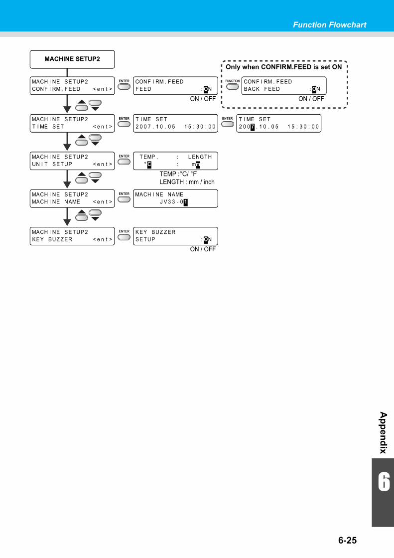
6-25
Function Flowchart
6
Ap
pen
dix
Only when CONFIRM.FEED is set ON
MACH I NE SE TUP 2CONF I RM . F EED < e n t >
CONF I RM . F EEDF EED : ON
MACHINE SETUP2
CONF I RM . F EEDBACK F EED : ON
TEMP :°C/ °FLENGTH : mm / inch
ON / OFF
T I ME SE T2 0 0 7 . 1 0 . 0 5 1 5 : 3 0 : 0 0
T I ME SE T2 0 0 7 . 1 0 . 0 5 1 5 : 3 0 : 0 0
MACH I NE SE TUP 2UN I T SE TUP < e n t >
T EMP . : L ENGTH° C : mm
MACH I NE SE TUP 2MACH I NE NAME < e n t >
MACH I NE NAMEJ V 3 3 - 0 1
ON / OFF
MACH I NE SE TUP 2KEY BUZ Z ER < e n t >
KEY BUZ Z ERSE TUP : ON
MACH I NE SE TUP 2T I ME SE T < e n t >
ON / OFF
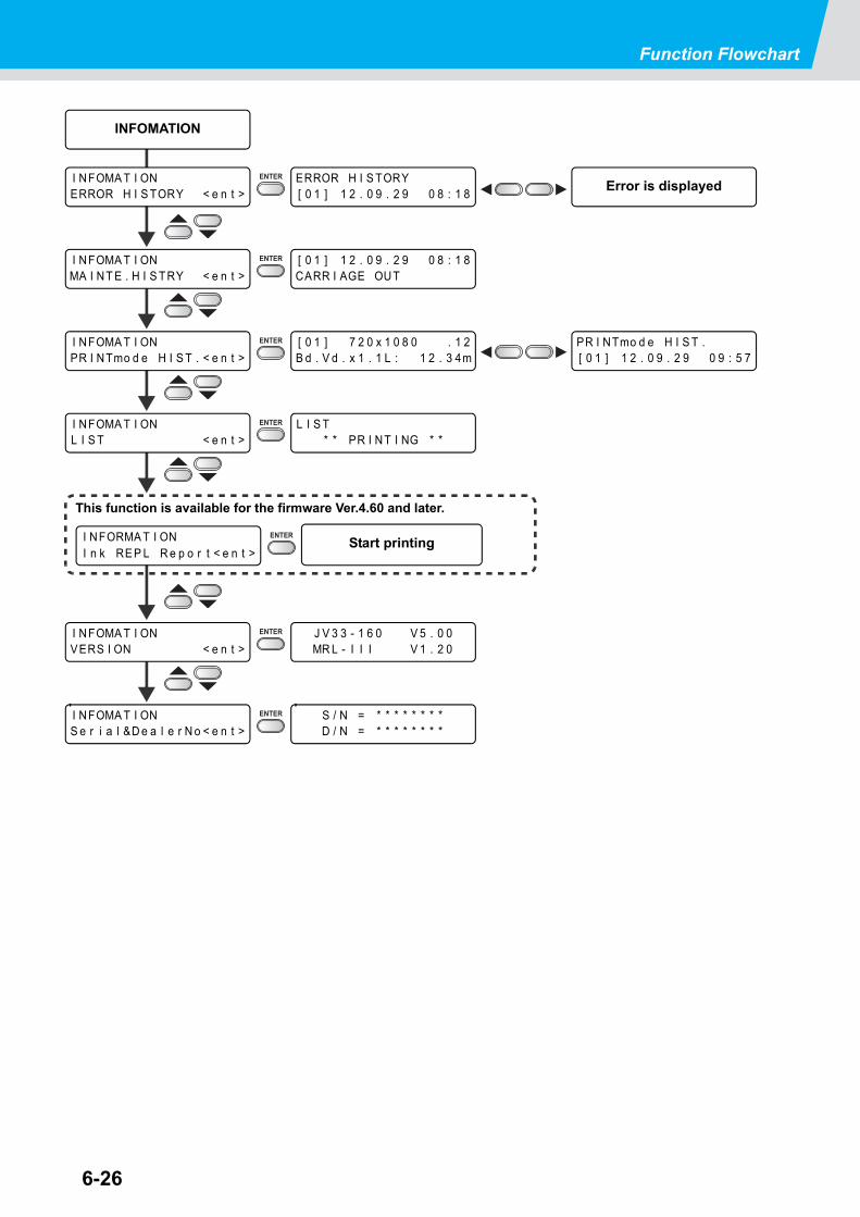
Function Flowchart
6-26
I NFOMA T I ONS e r i a l &D e a l e r N o < e n t >
S / N = * * * * * * * *D / N = * * * * * * * *
I NFOMA T I ONERROR H I S TORY < e n t >
ERROR H I S TORY[ 0 1 ] 1 2 . 0 9 . 2 9 0 8 : 1 8
INFOMATION
[ 0 1 ] 1 2 . 0 9 . 2 9 0 8 : 1 8CARR I AGE OUT
I NFOMA T I ONPR I NTmo d e H I S T . < e n t >
[ 0 1 ] 7 2 0 x 1 0 8 0 . 1 2B d . V d . x 1 . 1 L : 1 2 . 3 4m
I NFOMA T I ONL I S T < e n t >
L I S T* * PR I NT I NG * *
I NFOMA T I ONVERS I ON < e n t >
J V 3 3 - 1 6 0 V 5 . 0 0MR L - I I I V 1 . 2 0
I NFOMA T I ONMA I NT E . H I S TRY < e n t >
PR I NTmo d e H I S T .[ 0 1 ] 1 2 . 0 9 . 2 9 0 9 : 5 7
Error is displayed
This function is available for the firmware Ver.4.60 and later.
Start printingI NFORMA T I ONI n k REP L R e p o r t < e n t >

D201694-16-31012012

NH
FW : 5.3© MIMAKI ENGINEERING CO., LTD.2012


![interoperability.blob.core.windows.netinteroperability.blob.core.windows.net/web/MS-ES3/[MS-ES3]-161102… · 5 / 126 [MS-ES3] - v20161102 Microsoft JScript ECMA-262-1999 ECMAScript](https://static.fdocuments.us/doc/165x107/5ece296ef6bb9c0f49301db0/ms-es3-161102-5-126-ms-es3-v20161102-microsoft-jscript-ecma-262-1999-ecmascript.jpg)