Milton S. Hershey Medical Center Biomedical Research Building · Milton S. Hershey Medical Center...
21
Milton S. Hershey Medical Center Biomedical Research Building Joshua Zolko, Structural Option
Transcript of Milton S. Hershey Medical Center Biomedical Research Building · Milton S. Hershey Medical Center...

Milton S. Hershey Medical Center Biomedical Research Building
Joshua Zolko, Structural Option

Introduction
• The Biomedical Research Building (BMR) is located in Hershey, Pennsylvania.
• 245000 sq. ft, in 7 stories above grade • Built between 1991-1993 • Cost $49 million • Used a Bid-Build project delivery method • Used for Education and Laboratory space
Table of Contents • Introduction • Architecture • Structure • Process • HVAC • Lighting • Acoustics

Architecture
• Façade of the BMR consists of long horizontal concrete and limestone slabs, and black glazing
• Façade designed to relate to buildings already existing on campus
• Cylinder and Planar wall on corners add to the otherwise flat building
Table of Contents • Introduction • Architecture • Structure • Process • HVAC • Lighting • Acoustics

Structure
• The BMR is a monolithic concrete structure, using a one-way flat plate system with the average column size about 22” by 22”
• Building sits on a deep foundation system of caissons 3 to 7 feet in diameter
Table of Contents • Introduction • Architecture • Structure • Process • HVAC • Lighting • Acoustics

Structure
• Analysis shows that columns have an extra 35% capacity for applied loads
• Design of the lateral system maintained symmetry, resulting in only a 6” eccentricity.
Table of Contents • Introduction • Architecture • Structure • Process • HVAC • Lighting • Acoustics

Process
• Based on extra capacity of columns, goal was to be adding 3 extra stories to top of building, top story floor to floor height to be 24.6’ instead of the average 12.3’
• This extra space would serve for a studio or recreational setting for students.
Table of Contents • Introduction • Architecture • Structure • Process • HVAC • Lighting • Acoustics

Process
• Assumed gravity loads were to be: • 150 PSF dead • 40 PSF snow • 15 PSF superimposed • 80 PSF live
• Self weight of the columns and bracing beams factored in as well
Typical Column Section Table of Contents
• Introduction • Architecture • Structure • Process • HVAC • Lighting • Acoustics

Process
• Axial Loads calculated for a typical column over a 21’ by 35’ bay area.
• As loads increase, they approach total capacity
• This does not allow much room for applied moments from lateral or asymmetrical loading
Floor Load Capacity
10th 143.4K 2230K
9th 435.4K 2230K
8th 652.7K 2230K
7th 870K 2000K
6th 1164K 2000K
5th 1458K 2242K
4th 1752K 2242K
3rd 2046K 2855K
2nd 2340K 2855K
1st 2634K 2855K
Ground 2928K 4708K
Typical Column Axial Load
Table of Contents • Introduction • Architecture • Structure • Process • HVAC • Lighting • Acoustics

Process
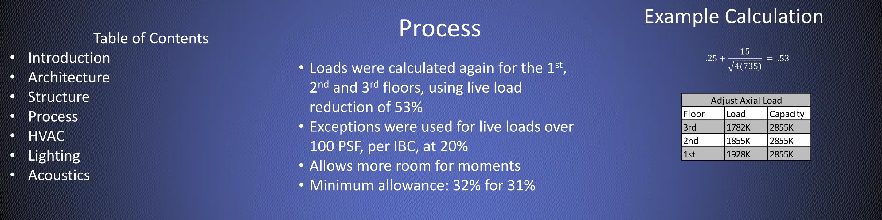
• Loads were calculated again for the 1st, 2nd and 3rd floors, using live load reduction of 53%
• Exceptions were used for live loads over 100 PSF, per IBC, at 20%
• Allows more room for moments
Floor Load Capacity
3rd 1782K 2855K
2nd 1855K 2855K
1st 1928K 2855K
Adjust Axial Load
Table of Contents • Introduction • Architecture • Structure • Process • HVAC • Lighting • Acoustics
Process
• Loads were calculated again for the 1st, 2nd and 3rd floors, using live load reduction of 53%
• Exceptions were used for live loads over 100 PSF, per IBC, at 20%
• Allows more room for moments • Minimum allowance: 32% for 31%
Floor Load Capacity
3rd 1782K 2855K
2nd 1855K 2855K
1st 1928K 2855K
Adjust Axial Load
.25 +15
4(735) = .53
Table of Contents • Introduction • Architecture • Structure • Process • HVAC • Lighting • Acoustics
Example Calculation

Process
• Bracing beams were necessitated through exceptionally long columns, about 22’ in height
• Beams were chosen to be 24” by 24” to match column sizes
• Would allow for an architectural feature on the top floor.
Bracing Beam Section Table of Contents
• Introduction • Architecture • Structure • Process • HVAC • Lighting • Acoustics
Process
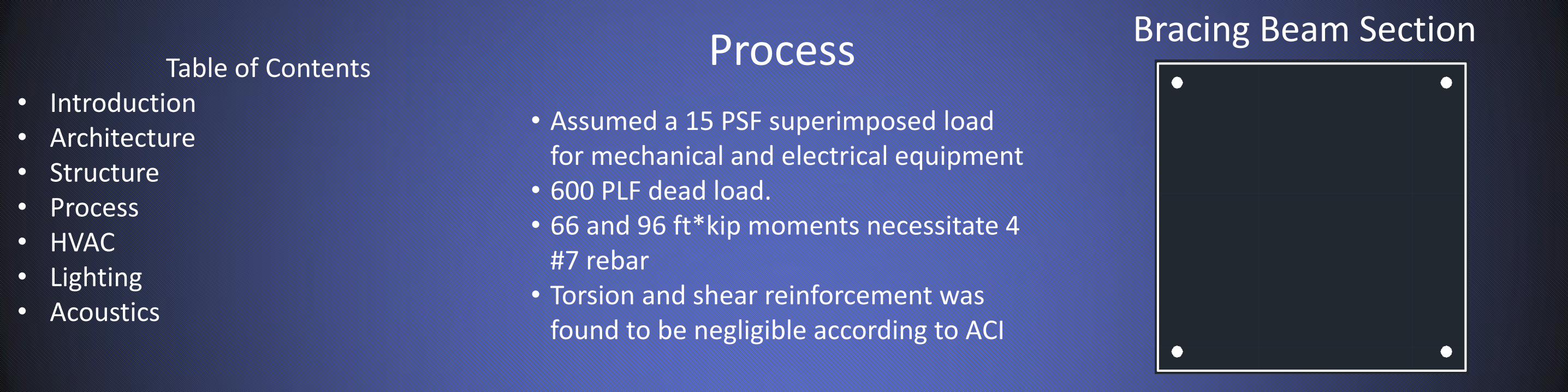
• Assumed a 15 PSF superimposed load for mechanical and electrical equipment
• 600 PLF dead load. • 66 and 96 ft*kip moments necessitate 4
#7 rebar • Torsion and shear reinforcement was
found to be negligible according to ACI
Bracing Beam Section Table of Contents
• Introduction • Architecture • Structure • Process • HVAC • Lighting • Acoustics

Process
• A RAM Model was developed to analyze the effect of controlling wind and earthquake forces.
• Addition was designed maintaining symmetry and negligible eccentricity as rest of building, minimizing unusual torsional effect and forces
RAM Model Table of Contents
• Introduction • Architecture • Structure • Process • HVAC • Lighting • Acoustics

Process
• Distributing story shear forces across all columns on a story by a factor of 1.5%, lead to a shear force of 9 kips
• Moment of 111 ft*kips per column • Story and Total drifts are well within
acceptable H/400 limits • Overturning is controlled by gravity
loads
Story Drifts Table of Contents
• Introduction • Architecture • Structure • Process • HVAC • Lighting • Acoustics

Process
Story Drifts
• Distributing story shear forces across all columns on a story by a factor of 1.5%, lead to a shear force of 9 kips
• Moment of 111 ft*kips per column • Story and Total drifts are well within
acceptable H/400 limits • Overturning is controlled by gravity
loads
Table of Contents • Introduction • Architecture • Structure • Process • HVAC • Lighting • Acoustics

HVAC (Breadth 1)
Insulation
• Calculated CFM requirements for the addition were found to be 86000 CFM • 4050 people at 20 CFM and 81000 sq
ft at .06 CFM • BTU Loads for CFM and people and
insulation were found to be 5 million BTU/HR for both heating and cooling
Table of Contents • Introduction • Architecture • Structure • Process • HVAC • Lighting • Acoustics

Lighting (Breadth 2)
Typical Luminaire
• For a recommended 500 lux for a work space, the total room of 90’ by 210’ with its 12 bays requires 200 luminaries, allowing 18 per bay
• Two systems were developed, one at 12.3’ high, and one at ceiling for the top story, but ceiling height would cast shadows
Table of Contents • Introduction • Architecture • Structure • Process • HVAC • Lighting • Acoustics

Acoustics (Breadth 3)
Calculations
• Acoustical tile was initially placed on ceiling, beams, columns, and carpeting was used.
• Created a “dead space” which would have been disconcerting to occupants
• Toned back acoustical insulation to just beams and columns, as well as carpeting
10𝑙𝑜𝑔19660 + 400
400= 17 𝑑𝐵
10𝑙𝑜𝑔11223 + 400
400= 15 𝑑𝐵
Table of Contents • Introduction • Architecture • Structure • Process • HVAC • Lighting • Acoustics

Questions?