
milltronics - Vision Solutions
36
Instruction Manual May 2008 MFA 4P milltronics
Transcript of milltronics - Vision Solutions

Instruction Manual May 2008
MFA 4Pmilltronics

© Siemens Milltronics Process Instruments Inc. 2008
Safety Guidelines: Warning notices must be observed to ensure personal safety as well as that of
others, and to protect the product and the connected equipment. These warning notices are
accompanied by a clarification of the level of caution to be observed.
Qualified Personnel: This device/system may only be set up and operated in conjunction with this
manual. Qualified personnel are only authorized to install and operate this equipment in accordance with
established safety practices and standards.
Unit Repair and Excluded Liability:
• The user is responsible for all changes and repairs made to the device by the user or the user’s
agent.
• All new components are to be provided by Siemens Milltronics Process Instruments Inc.
• Restrict repair to faulty components only.
• Do not reuse faulty components.
Warning: This product can only function properly and safely if it is correctly transported, stored,
installed, set up, operated, and maintained.
This product is intended for use in industrial areas. Operation of this equipment in a residential area
may cause interference to several frequency based communications.
Note: Always use product in accordance with specifications.
Copyright Siemens Milltronics Process Instruments Inc. 2008. All Rights Reserved
Disclaimer of Liability
This document is available in bound version and in
electronic version. We encourage users to purchase
authorized bound manuals, or to view electronic versions
as designed and authored by Siemens Milltronics Process
Instruments Inc. Siemens Milltronics Process Instruments
Inc. will not be responsible for the contents of partial or
whole reproductions of either bound or electronic
versions.
While we have verified the contents of this
manual for agreement with the
instrumentation described, variations
remain possible. Thus we cannot
guarantee full agreement. The contents of
this manual are regularly reviewed and
corrections are included in subsequent
editions. We welcome all suggestions for
improvement.
Technical data subject to change.
MILLTRONICS®is a registered trademark of Siemens Milltronics Process Instruments Inc.
Contact SMPI Technical Publications European Authorized Representative
at the following address: Technical Publications Siemens AG
Siemens Milltronics Process Instruments Inc. Industry Sector
1954 Technology Drive, P.O. Box 4225 76181 Karlsruhe
Peterborough, Ontario, Canada, K9J 7B1 Deutschland
Email: [email protected]
• For a selection of Siemens Milltronics level measurement manuals, go to:
www. siemens.com/processautomation. Under Process Instrumentation, select Level Measurement and then go to the manual archive listed under the product family.
• For a selection of Siemens Milltronics weighing manuals, go to:
www. siemens.com/processautomation. Under Weighing Technology, select Continuous Weighing Systems and then go to the manual archive listed under the product family.

i
Tab
le o
f Co
nte
nts
Table of Contents
Milltronics MFA 4p ............................................................................................................. 1
Safety Notes .............................................................................................................................................1
The Manual ...............................................................................................................................................1
Specifications ...................................................................................................................... 2
Installation ........................................................................................................................... 4
Milltronics MFA 4p ........................................................................................................................4
Probe ................................................................................................................................................4
Wiring ...............................................................................................................................................4
Dimensions ...............................................................................................................................................5
MFA 4p .............................................................................................................................................5
Layout .........................................................................................................................................................7
Interconnection ...................................................................................................................8
MSP-1, 3, or 9 Probe with RMA (remote mounted pre-amplifier) ...............................................8
MSP-12 Probe with IMA (internally mounted pre-amplifier) ........................................................8
XPP-5 with IMA (internally mounted pre-amplifier) .......................................................................9
Connection to power: ...........................................................................................................................10
Wiring .................................................................................................................................. 11
MFA 4p Wiring for Automatic Start Delay ......................................................................................11
Operating Principles ........................................................................................................ 12
MFA 4p .....................................................................................................................................................12
Probe ........................................................................................................................................................12
Pre-Amplifier (IMA and RMA) ............................................................................................................13
MFA 4p Operation .................................................................................................................................13
Calibration ..............................................................................................................................................14
Underspeed ..................................................................................................................................14
Overspeed ....................................................................................................................................15
Signal Generator Interface .................................................................................................................16
Probes ................................................................................................................................. 17
Mini Sensing Probe MSP-1 .................................................................................................................17
High Temperature Probe MSP-3 ........................................................................................................17
Stainless Steel Probe MSP-9 ..............................................................................................................18
Mounting Details .........................................................................................................................18
Standard Probe MSP-12 .....................................................................................................................19
Hazardous Locations XPP-5 ................................................................................................................20
Interconnection Diagram for the XPP-5 .................................................................................21
Mounting Details ...................................................................................................................................22
Applications .......................................................................................................................23
Bucket Elevators ...................................................................................................................................23
Shafts .......................................................................................................................................................24

ii
Tab
le o
f C
on
ten
ts
Belt Conveyors .......................................................................................................................................24
Screw Conveyors ...................................................................................................................................24
Non-Ferrous Window .........................................................................................................................25
Bucket Elevator ......................................................................................................................................25
Rotating Shaft of Rotary Feeder ........................................................................................................26
Drive Sprocket on Rotary Feeder ......................................................................................................26
Screw Conveyor Flights .......................................................................................................................27
End Bearing on Screw Conveyor ......................................................................................................27
Troubleshooting ................................................................................................................28
Maintenance ......................................................................................................................29

7ML19985FM01 MFA 4p - INSTRUCTION MANUAL Page 1
Intro
du
ctio
n
Milltronics MFA 4p
Milltronics MFA 4p is a highly sensitive, single setpoint motion sensor alarm unit, used
with MSP and XPP probes. The probe detects an increase or decrease in the speed of
rotating, reciprocating, or conveying equipment and sends the information to the MFA 4p.
The MFA 4p works with a pre-amplifier which can be internal to the motion sensing
probe, or remote from the motion sensing probe.
Pulses generated from the probe are continually compared to the adjustable setpoint. If
the pulse rate is lower than the setpoint, the alarm relays operating in a faiI-safe mode
will de-energize, indicating failure. The relays will not energize until the pulse rate
increases above the setpoint.
Safety Notes
Special attention must be paid to warnings and notes highlighted from the rest of the text
by grey boxes.
The Manual
This instruction manual covers the installation, operation and maintenance of the
Milltronics MFA 4p. It is essential that this manual be referred to for proper installation
and operation of your unit. Adhering to the installation and operating procedures will
insure a quick, trouble free installation and allow for the maximum accuracy and
reliability of your motion sensing alarm unit and probes.
If you have any questions, comments, or suggestions about the manual contents, please
email us at [email protected].
For the complete library of Siemens Milltronics manuals,
go to www.siemens.com/processautomation.
Note: This product is intended for use in industrial areas. Operation of this
equipment in a residential area may cause interference to several frequency
based communications.
WARNING means that failure to observe the necessary precautions can result in death, serious injury, and/or considerable material damage.
Note: means important information about the product or that part of the operating
manual.
Page 2 MFA 4p - INSTRUCTION MANUAL 7ML19985FM01
Sp
ec
ific
ati
on
s
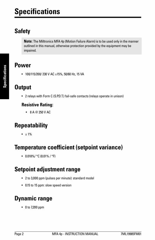
Specifications
Safety
Power
� 100/115/200/ 230 V AC ±15%, 50/60 Hz, 15 VA
Output
� 2 relays with Form C (S.P.D.T.) fail-safe contacts (relays operate in unison)
Resistive Rating:
� 8 A @ 250 V AC
Repeatability
� ± 1%
Temperature coefficient (setpoint variance)
� 0.018%/ °C (0.01% / °F)
Setpoint adjustment range
� 2 to 3,000 ppm (pulses per minute): standard model
� 0.15 to 15 ppm: slow speed version
Dynamic range
� 0 to 7,200 ppm
Note: The Milltronics MFA 4p (Motion Failure Alarm) is to be used only in the manner
outlined in this manual, otherwise protection provided by the equipment may be
impaired.
7ML19985FM01 MFA 4p - INSTRUCTION MANUAL Page 3
Insta
llatio
n
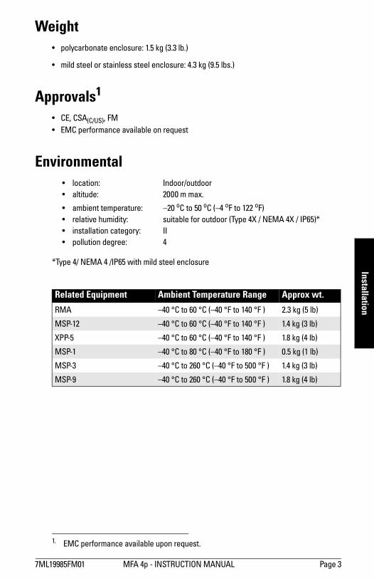
Weight
� polycarbonate enclosure: 1.5 kg (3.3 lb.)
� mild steel or stainless steel enclosure: 4.3 kg (9.5 lbs.)
Approvals1
� CE, CSA(C/US), FM
� EMC performance available on request
Environmental
� location: Indoor/outdoor
� altitude: 2000 m max.
� ambient temperature: �20 oC to 50 oC (�4 oF to 122 oF)
� relative humidity: suitable for outdoor (Type 4X / NEMA 4X / IP65)*
� installation category: II
� pollution degree: 4
*Type 4/ NEMA 4 /IP65 with mild steel enclosure
1. EMC performance available upon request.
Related Equipment Ambient Temperature Range Approx wt.
RMA �40 °C to 60 °C (�40 °F to 140 °F ) 2.3 kg (5 lb)
MSP-12 �40 °C to 60 °C (�40 °F to 140 °F ) 1.4 kg (3 lb)
XPP-5 �40 °C to 60 °C (�40 °F to 140 °F ) 1.8 kg (4 lb)
MSP-1 �40 °C to 80 °C (�40 °F to 180 °F ) 0.5 kg (1 lb)
MSP-3 �40 °C to 260 °C (�40 °F to 500 °F ) 1.4 kg (3 lb)
MSP-9 �40 °C to 260 °C (�40 °F to 500 °F ) 1.8 kg (4 lb)

Page 4 MFA 4p - INSTRUCTION MANUAL 7ML19985FM01
Inst
all
ati
on
Installation
Milltronics MFA 4p
The MFA 4p (and RMA if applicable) must be mounted in a non-hazardous area that is
clean, dry, vibration-free, within the ambient temperature range, and non-corrosive to the
electronics or its enclosure. The door should be accessible for viewing and to allow
calibration of the MFA 4p.
Probe
The probe should be mounted onto a vibration free structure using the mounting flange.
The gap between probe and target should be large enough to prevent the target from
damaging the probe. The probe environment must be within the probe's ambient
temperature range and non-corrosive to the probe's body. Refer to Applications drawings
on page 23.
The probe design detects a changing magnetic field, typically caused by a ferromagnetic
target disturbing the probe's magnetic field. Extremely strong magnetic fields (like those
produced by the 30A/m requirements of 1EC 60004-8, Power Frequency Magnetic Field
Immunity test) will be detected and will result in loss of functionality.
Functionality loss indicators:
� alarm conditions by relay trip
� false pulse readings in LED1
Consider the probe location carefully before installation. Avoid strong magnetic fields
(50/60 Hz) from nearby power transformers, heater elements, or large industrial motors,
because these can affect the probe�s performance.
Wiring
Where possible, the probe components should be interconnected via flexible conduit.
This allows for easier removal or adjustment of the probe and mounting flange assembly.
Note: Do not mount MFA 4p in direct sunlight.
Note: Installation shall only be performed by qualified personnel and in accordance
with local governing regulations.

7ML19985FM01 MFA 4p - INSTRUCTION MANUAL Page 5
Insta
llatio
n
Dimensions
MFA 4p
Type 4X / NEMA 4X / IP65 Polycarbonate Enclosure
Notes: � Non-metallic enclosure does not provide grounding between conduit
connections: use grounding type bushings and jumpers.
� Use only approved, suitable size hubs for watertight application.
160 mm (6.325")
131 mm (5.138")
15mm (0.59")
6 mm (0.25") 82 mm
(3.225")
240 mm (9.455")
228 mm (8.975")
lid screwsmounting holes 4.3 mm (0.170") dia. 4 places Suitable location for conduit entrance
Page 6 MFA 4p - INSTRUCTION MANUAL 7ML19985FM01
Inst
all
ati
on
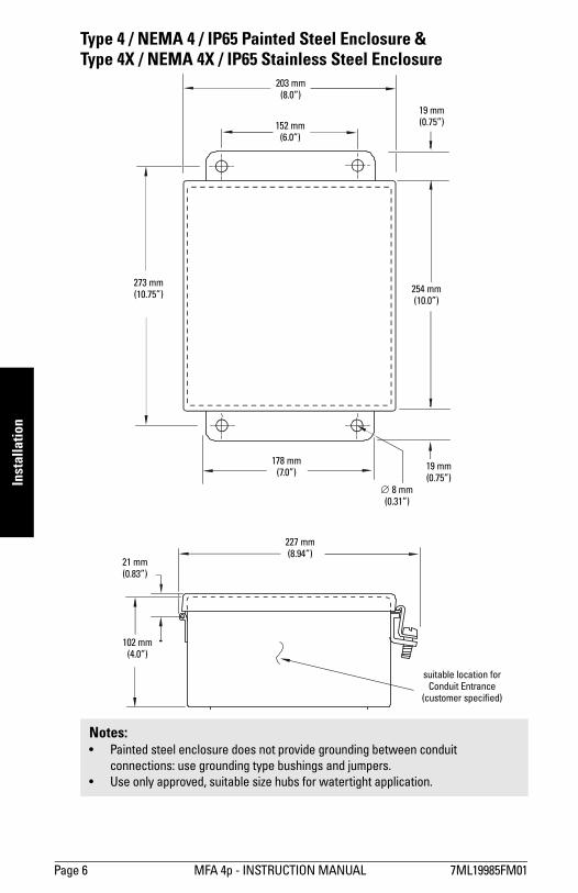
Type 4 / NEMA 4 / IP65 Painted Steel Enclosure & Type 4X / NEMA 4X / IP65 Stainless Steel Enclosure
Notes: � Painted steel enclosure does not provide grounding between conduit
connections: use grounding type bushings and jumpers.
� Use only approved, suitable size hubs for watertight application.
203 mm(8.0�)
152 mm(6.0�)
19 mm(0.75�)
273 mm (10.75�)
254 mm(10.0�)
178 mm(7.0�)
∅ 8 mm(0.31�)
19 mm(0.75�)
227 mm(8.94�)
102 mm(4.0�)
21 mm(0.83�)
suitable location for Conduit Entrance
(customer specified)
7ML19985FM01 MFA 4p - INSTRUCTION MANUAL Page 7
Inte
rco
nn
ec
tion
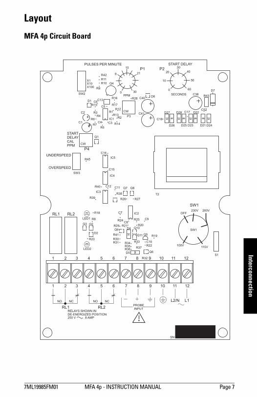
Layout
MFA 4p Circuit Board
R42
R11
R10
R9
SW2
Q4
Q1
P4
RL1 RL2
C13
C5
C6
X1X10X100
C2
C4 C3
C16
CW
CW
C15
IC5
IC2
IC3
IC4
R14
R2IC1C1
R15
R3R13
R1R12
R17
R28R43
D7
P2P1PULSES PER MINUTE START DELAY
START
DELAY
CAL
PPM
UNDERSPEED
OVERSPEED
P3C41
C18
C17C52
C40
C38D6
D27
D26
D28
D25 D23
D22
D21 D24
R16
9
15
21
00
10
20 40
50
6030
30
PPM
T2
SECONDS
R4
R5R7
R45
SW3
R19
OFF
S1
115V100V
230V 200V
SW1
R32
R22
SN
R33
R37R36R35R34
R41
R30R31
R39
R40
R38
R26 R27
C12 C11
C7
C10
D4
D5
C9
Q10Q9
Q7 Q8
Q3 Q2
D2
Q6
Q11 Q5
C8R24
R18
R8LED1
LED2
NO NONC
1
1
2
2
3
3
4
4
5
5
6
6
7
7
8
8
PROBEINPUT
9
9
SW1
10
10
11
11
12
12
L2/N
RL1 RL2
L1
RELAYS SHOWN INDE-ENERGIZED POSITION250 V 8 AMP
NC
R29
R23
R21
R25
R20
R6
D1
Page 8 MFA 4p - INSTRUCTION MANUAL 7ML19985FM01
Inte
rco
nn
ec
tio
n
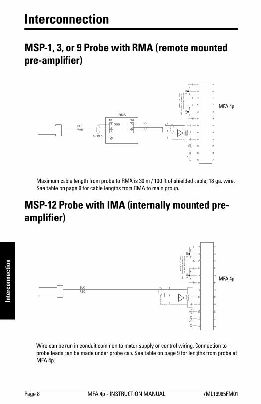
Interconnection
MSP-1, 3, or 9 Probe with RMA (remote mounted pre-amplifier)
Maximum cable length from probe to RMA is 30 m / 100 ft of shielded cable, 18 ga. wire.
See table on page 9 for cable lengths from RMA to main group.
MSP-12 Probe with IMA (internally mounted pre-amplifier)
Wire can be run in conduit common to motor supply or control wiring. Connection to
probe leads can be made under probe cap. See table on page 9 for lengths from probe at
MFA 4p.
GND
SHIELD
BLK
RMA
WHT
3
2
1
NO
NO
NC
1 1
2 2
3 3
4 4
5 5
6 6
77 7
88 8
PR
OB
EIN
PU
T
99 9
10
10
11
11
12
12
L2/N
RL1
RL2
L1
RE
LA
YS
SH
OW
NIN
DE
-EN
ER
GIZ
ED
PO
SIT
ION
250
V8
AM
P
NC
3
2
1
TB1 TB2
MFA 4p
BLK
RED
NO
NO
NC
1 1
2 2
3 3
4 4
5 5
6 6
77 7
88 8
PR
OB
EIN
PU
T
99 9
10
10
11
11
12
12
L2/N
L1
NC
RL1
RL2
RE
LA
YS
SH
OW
NIN
DE
-EN
ER
GIZ
ED
PO
SIT
ION
25
0V
8A
MP
MFA 4p
7ML19985FM01 MFA 4p - INSTRUCTION MANUAL Page 9
Inte
rco
nn
ec
tion
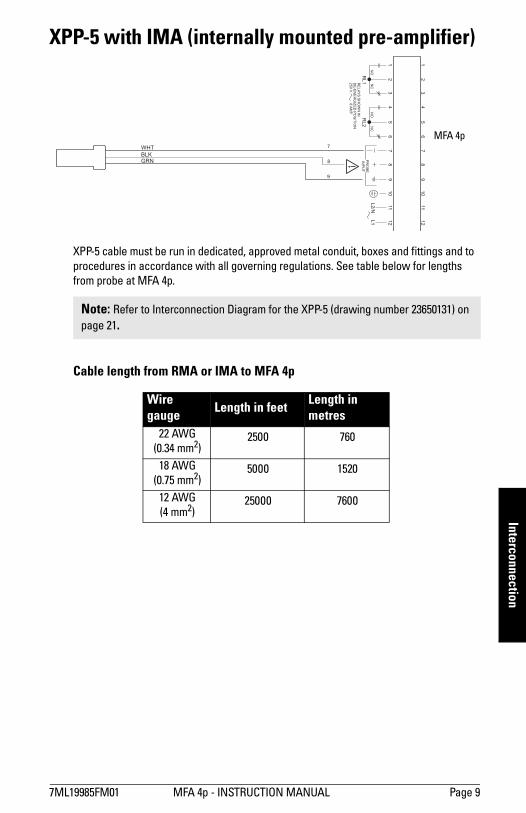
XPP-5 with IMA (internally mounted pre-amplifier)
XPP-5 cable must be run in dedicated, approved metal conduit, boxes and fittings and to
procedures in accordance with all governing regulations. See table below for lengths
from probe at MFA 4p.
Cable length from RMA or IMA to MFA 4p
Note: Refer to Interconnection Diagram for the XPP-5 (drawing number 23650131) on
page 21.
Wire gauge
Length in feetLength in metres
22 AWG
(0.34 mm2)2500 760
18 AWG
(0.75 mm2)5000 1520
12 AWG
(4 mm2)25000 7600
WHT
BLKGRN
NO
NO
NC
1 1
2 2
3 3
4 4
5 5
6 6
77 7
88 8
PR
OB
EIN
PU
T
99 9
10
10
11
11
12
12
L2
/N
RL
1R
L2
L1
RE
LA
YS
SH
OW
NIN
DE
-EN
ER
GIZ
ED
PO
SIT
ION
250
V8
AM
P
NC
MFA 4p

Page 10 MFA 4p � INSTRUCTION MANUAL 7ML19985FM01
Wir
ing
Connection to power:
� Terminal 10 must be connected to reliable ground.
� The equipment must be protected by a 15A fuse or circuit breaker in the building
installation.
� A circuit breaker or switch in the building installation, marked as the disconnect
switch, shall be in close proximity to the equipment and within easy reach of the
operator.
� AC input circuit, relay circuits, min. 14 AWG copper wire
� Recommended torque on terminal clamping screws, 7 in.lbs. max.
WARNING: All field wiring must have insulation suitable for at least 250 V.
NO NONC
1
1
2
2
3
3
4
4
5
5
6
6
7
7
8
8
PROBEINPUT
9
9
10
10
11
11
12
12
L2/N
RL1 RL2
L1
RELAYS SHOWN INDE-ENERGIZED POSITION250 V 8 AMP
NC

7ML19985FM01 MFA 4p - INSTRUCTION MANUAL Page 11
Wirin
g
Wiring
MFA 4p Wiring for Automatic Start Delay
Should the Time Delay feature on start-up not be required, power should be applied
continuously from a separate source and the potentiometer turned to zero. This is usually
necessary for automatic up-stream start up of conveying devices after the down-stream
drive has reached its operation speed.
Notes:1. Interlocks and Safety Pull Switches are not shown.
2. If START is initiated by programmable logic controller, closure time may be too
brief to allow MFA 4p contact to latch. In this case, program a timer contact
into the circuit.
3. CSA requires an 8A or less fuse to protect contacts. For 240 V AC, protect the
contacts with a 1500 VA transformer as well.
M
M
N
N
L
L
TB-1
TB-1
CONTACTOR
CONTACTOR
MFA 4p
MFA 4p
121
1
L L/N
START
115/230V AC 50/60 HZ
START
OR
STOP
STOP
SEE NOTE 3
SEE NOTE 3
SEE NOTE 2
MFA 4p
MFA 4p
TB-1
TB-1
HOLD UNTIL UP TO SPEED
1/4
1/4
2/5
2/5
M
M
12
11
11
10
10
G
G
Page 12 MFA 4p � INSTRUCTION MANUAL 7ML19985FM01
Wir
ing
Operating Principles
MFA 4p
Milltronics MFA 4p is a highly sensitive, single setpoint motion sensor alarm unit, used
with MSP and XPP probes. The probe detects an increase or decrease in the speed of
rotating, reciprocating, or conveying equipment and sends the information to the MFA 4p.
The MFA 4p works with a pre-amplifier which can be internal to the motion sensing
probe, or remote from the motion sensing probe.
Pulses generated from the probe are continually compared to the adjustable setpoint. If
the pulse rate is lower than the setpoint, the alarm relays operating in a faiI-safe mode
will de-energize, indicating failure. The relays will not energize until the pulse rate
increases above the setpoint.
Probe
The Milltronics probes work on the principle of Faraday�s Laws of Electromagnetic
Induction. When a ferromagnetic object enters the probe�s permanent magnetic field, it
distorts the flux causing it to cut the coil windings and generate a voltage. This voltage is
proportional to the strength of the magnet and the number of wire turns in the coil
(constant in the Milltronics probes) and the speed at which the ferrous target passes
through the flux. The generated voltage is also inversely proportional to the square of the
distance between the target and the probe.
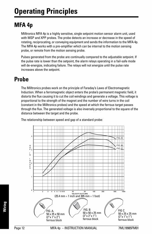
The relationship between speed and gap of a standard probe:
FIG. A. 50 x 25 x 50 mm (2�x 1�x 2�)ferrous block
FIG C 50 x 25 x 25 mm (2�x 1�x 1�)ferrous block
FIG. B 50 x 50 x 25 mm (2�x 2�x 1�)ferrous block
(25.4 mm = 1 inch and 305 mm = 1 foot)

7ML19985FM01 MFA 4p - INSTRUCTION MANUAL Page 13
Wirin
g
The resultant line indicates the threshold tolerance of the accompanying MFA 4p
electronics. For example, in FIG. A, a 100 mm (4") gap requires a minimum velocity of
about 10 m / minute (35 ft / minute): with a velocity of 0.61 m / minute (2 ft / minute), a
maximum gap of 31 mm (1.25") is possible.
The graph was plotted from tests using four ferrous blocks set equidistantly on a
406 mm (16") diameter circle on a non-ferrous disc.
The physical shape of the ferrous target generally becomes important at low velocities or
large gaps. At these points, tests indicate that a cubic shape gives the best results due to
the sudden change it causes in the magnetic field.
An increase in block size beyond 50 x 50 x 25 mm (2" X 2" X 1") is generally not as effective
as minimizing the gap, except at very low velocities.
The Milltronics Mini Sensing Probe, MSP-1
� The MSP-1 is approximately one-quarter the size of the standard probe with about
one-eighth the sensitivity.
� Divide all operating values by 0.125 to obtain the specifications of the MSP-1.
For example, with a gap of 12 mm (0.5"), the minimum velocity is approximately
60 m / min. (200 ft / min.), and with a velocity of 0.6 m / min. (2 ft / min. )
a maximum gap of 0.125" (3 mm) is possible.
Milltronics manufactures probes to suit a wide variety of environments: low temperature,
high temperature, corrosive, and Class I, II and III applications.
Pre-Amplifier (IMA and RMA)
The pre-amplifier accepts the voltage pulses generated by the probe and converts them
into noise-immune current pulses. Current levels are 12 mA low and 45 mA high. The pre-
amplifier comes internally mounted in the probe, or in an enclosure for remote mounting.
Internally mounted pre-amplifiers are called IMAs. Remote mounted pre-amplifiers are
called RMAs.
MFA 4p Operation
The MFA 4p provides a short circuit protected, +24 V DC unregulated supply to the pre-
amp. In the event that the interconnecting wiring is shorted, output current from the
MFA 4p is automatically limited and the on-board alarm relays are de-energized to
indicate failure.
The output current pulses from the pre-amp are super-imposed onto the dc current
supply. These are monitored by Probe LED 1, which is illuminated at the rate of the
incoming pulses and is useful for positioning the probe.
The rate at which the pulses are received by the MFA 4p is compared to a setpoint
reference signal from the time base generator.
Note: 25.4 mm = 1 inch and 0.305 m = 1 foot

Page 14 MFA 4p � INSTRUCTION MANUAL 7ML19985FM01
Wir
ing
Although two pulses within range are required to energize the relays, as long as the
frequency of the incoming pulses exceeds the setpoint frequency (or is less than that of
the setpoint in the case of overspeed detection), the MFA 4p keeps the alarm relays
energized. The reference generator is frequency adjustable by the pulses per minute
(ppm) switch and potentiometer.
The alarm relays will de-energize after two time constants of the setpoint when the
frequency of the incoming pulses falls below that of the setpoint (or exceeds that of the
setpoint in the case of overspeed detection). The relay status is indicated by Relay LED 2,
which is illuminated when the relays are energized (normal).
The MFA 4p has a 0 to 60 second time delay feature, allowing the monitored device to
accelerate to normal running speed before monitoring begins.
This feature is activated when power is applied to the MFA 4p in parallel with the motor
starter contact coil. The time delay circuit simulates normal operating conditions for the
amount of time as set by the Start Delay potentiometer, keeping the alarm relays
energized. If the monitored device does not reach normal speed before the set time
period, the relays will de-energize giving an alarm condition. This feature is not applicable
in the overspeed detection mode.
Calibration
The probe and pre-amplifier require no calibration.
Connect the probe, pre-amp, and MFA 4p as shown in the Interconnection diagrams on
pages 8 and 9. Connect the MFA 4p to power as shown in the Power Connection diagram
on page 10, and if applicable, as shown for Automatic Start Delay on page 11.
MFA 4p (Refer to MFA 4p Circuit Board layout on page 7.)
1. Operate monitored equipment at its normal operating speed.
2. Confirm that Probe LED 1 is pulsing at a regular frequency.
3. Set Start Delay fully counter-clockwise (CCW) to 0 seconds.
Underspeed
1. Set switch SW3 to Underspeed.
2. Set pulses per minute (ppm) switch SW2 to X 100 position.
3. Turn ppm potentiometer fully clockwise (CW) to 30.
4. Determine incoming pulse rate by slowly turning ppm potentiometer CCW until relay
LED 2 goes on. As the MFA 4p requires 2 pulses within range before energizing
relays, low ppm applications (e.g. 2 ppm) may require stepping of potentiometer at
appropriate time intervals.
Note: To help the calibration procedure, short N.O. contacts of relays to prevent
motor shut-down (terminals 1 to 2 and/or 4 to 5). This allows the system to run
uninterrupted until an operating setpoint is established.
7ML19985FM01 MFA 4p - INSTRUCTION MANUAL Page 15
Wirin
g
5. If no response is obtained when you set the ppm potentiometer to 3 (below this
stability suffers), reset potentiometer fully CW, set switch SW2 to X 10 and then X 1
if required, and repeat step 4.
6. When Relay LED 2 goes on, indicating the incoming pulse rate, turn potentiometer
CCW slightly past this point to obtain an operating setpoint that allows for normal
fluctuations due to load and voltage variations. For 50% of full speed, set
potentiometer (and SW2 if required) to halfway between incoming pulse rate of
normal speed and 0 ppm.
7. Set Start Delay by adjusting potentiometer so that equipment being monitored can
attain normal operating speed before LED 2 can turn off.
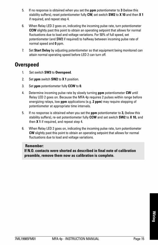
Overspeed
1. Set switch SW3 to Overspeed.
2. Set ppm switch SW2 to X 1 position.
3. Set ppm potentiometer fully CCW to 0.
4. Determine incoming pulse rate by slowly turning ppm potentiometer CW until
Relay LED 2 goes on. Because the MFA 4p requires 2 pulses within range before
energizing relays, low ppm applications (e.g. 2 ppm) may require stepping of
potentiometer at appropriate time intervals.
5. If no response is obtained when you set the ppm potentiometer to 3, (below this
stability suffers), re-set potentiometer fully CCW and set switch SW2 to X 10, and
then X 1 if required, and repeat step 4.
6. When Relay LED 2 goes on, indicating the incoming pulse rate, turn potentiometer
CW slightly past this point to obtain an operating setpoint that allows for normal
fluctuations due to load and voltage variations.
Remember: If N.O. contacts were shorted as described in final note of calibration preamble, remove them now as calibration is complete.

Page 16 MFA 4p � INSTRUCTION MANUAL 7ML19985FM01
Pro
be
s
Signal Generator Interface
The following circuit may be used for calibrating or for troubleshooting the MFA 4p.
470 to 620 ohm 2W
to MFA 4p
TB1 10K ohm1/4 W
2N4401
signal generator
3V p square
6 V p-p sine
6V p-p square
0 V
O V
O V
Circuit substitutes operating probe and pre-amp.
Set signal generator for:
8
7
7ML19985FM01 MFA 4p - INSTRUCTION MANUAL Page 17
Pro
be
s
Probes
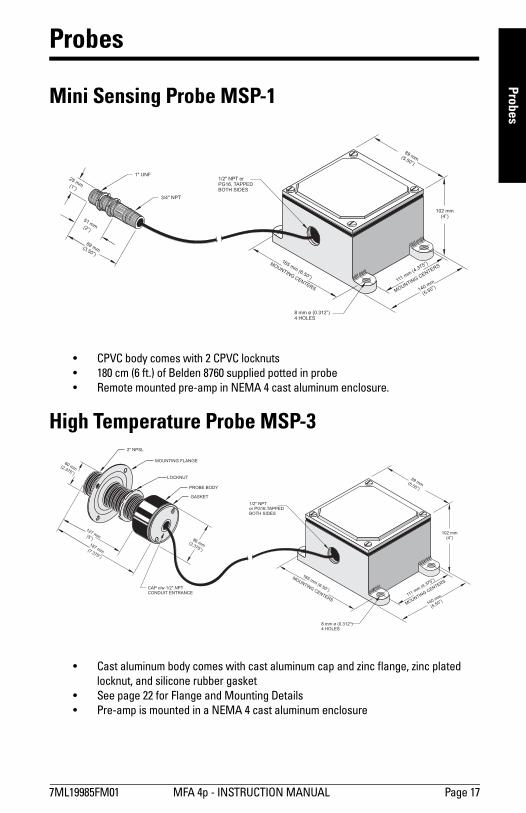
Mini Sensing Probe MSP-1
� CPVC body comes with 2 CPVC locknuts
� 180 cm (6 ft.) of Belden 8760 supplied potted in probe
� Remote mounted pre-amp in NEMA 4 cast aluminum enclosure.
High Temperature Probe MSP-3
� Cast aluminum body comes with cast aluminum cap and zinc flange, zinc plated
locknut, and silicone rubber gasket
� See page 22 for Flange and Mounting Details
� Pre-amp is mounted in a NEMA 4 cast aluminum enclosure
1" UNF1/2" NPT orPG16, TAPPEDBOTH SIDES
102 mm(4”)
8 mm ø (0.312”)4 HOLES
3/4" NPT
25 mm
51 mm
89 mm
165 mm(6.50”)
111 mm(4.375”)
140 mm
(5.50”)
89 mm
(1”)
(2”)
(3.50”)
MOUNTINGCENTERS
MOUNTING
CENTERS
(5.50”)
2" NPSL
1/2" NPTor PG16,TAPPEDBOTH SIDES
102 mm(4”)
8 mm ø (0.312”)4 HOLES
MOUNTING FLANGE
LOCKNUT
PROBE BODY
CAP c/w 1/2" NPTCONDUIT ENTRANCE
GASKET
60 mm
86 mm
127 mm
187 mm
165 mm(6.50”)
111 mm(4.375”)
140 mm
(5.50”)
89 mm
(2.375”)
(3.375”)
(5”)
(7.375”)
MOUNTINGCENTERS
MOUNTING
CENTERS
(5.50”)

Page 18 MFA 4p � INSTRUCTION MANUAL 7ML19985FM01
Pro
be
s
Stainless Steel Probe MSP-9
Mounting Details
� For high temperature and corrosion resistance applications
� 304 stainless steel body comes with stainless steel clamp and silicone gasket
� 1.5 m (5 ft.) Belden 83321 Teflon®1 cable potted in probe
� Pre-amp is mounted in an enamel painted steel Hammond 1414N4E enclosure
1. Teflon is a registered trademark of E.I. du Pont de Nemours and Company
111 mm(4.375”)
8 mm ø (0.312”)4 PLACES
CAP c/w22 mm ø HOLE(0.875”)
GASKET
86 mm ø(3.375”)
22 mm ø (0.875”)2 PLACES
CLAMPS4 PLACES
51 mm(2”)
178 mm
171 mm(6.75”)
152 mm(6”)
191 mm(7.50”)
102 mm(4”)
152 mm
(6”)MOUNTIN
GCENTERS
(7”)
MOUNTINGCENTERS
102mm (4�)
102 mm (4")
probe flange
95 mm (3.75") diameter Probe clearance hole
panel
6 mm (0.25") diameter four holes equally spaced on a 114 mm (4.5") BCD

7ML19985FM01 MFA 4p - INSTRUCTION MANUAL Page 19
Pro
be
s
Standard Probe MSP-12
� Phenolic body comes with die-cast aluminum cap and zinc flange, zinc plated
locknut, and neoprene gasket
� See page 22 for Flange and Mounting Details
� Pre-amp is potted in the probe body and comes with two 127 mm (5") long hook-up
wires
CAP c/w½" NPT or PG16CONDUIT ENTRANCE
LOCKNUT
MOUNTINGFLANGE
2" NPSL
PROBE BODY
GASKET
60 mm
86 mm
(2.375”)
(3.375”)187 mm
127 mm(5”)
(7.375”)
Page 20 MFA 4p � INSTRUCTION MANUAL 7ML19985FM01
Pro
be
s
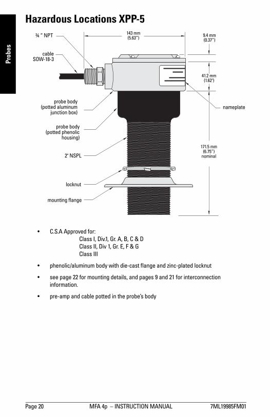
Hazardous Locations XPP-5
� C.S.A Approved for:
Class I, Div.1, Gr. A, B, C & D
Class II, Div 1, Gr. E, F & G
Class III
� phenolic/aluminum body with die-cast flange and zinc-plated locknut
� see page 22 for mounting details, and pages 9 and 21 for interconnection
information.
� pre-amp and cable potted in the probe�s body
cableSOW-18-3
probe body(potted phenolic
housing)
probe body(potted aluminum
junction box)
mounting flange
locknut
nameplate
¾ � NPT
171.5 mm (6.75�)
nominal
9.4 mm (0.37�)
41.2 mm(1.62")
143 mm (5.63�)
2" NSPL
7ML19985FM01 MFA 4p - INSTRUCTION MANUAL Page 21
Pro
be
s
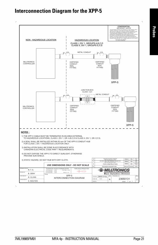
Interconnection Diagram for the XPP-5
1=1
11
R. CLOSS
B. GRAY
N. T. S.
S. NGUYEN
XPP-5INTERCONNECTION DIAGRAM
2365013102
23650131 2
RWG
RWG
RWG
SN
SN
SN
27/00MARCH
APRIL18/00
JULY11/00
0
1
2
FOR CONSTRUCTION
REVISED CABLE AND TERMINAL CONNECTORPER ECN #00-000-0-0037
REVISED HOUSING THREADSPER ECN #00-000-0-0070
NOTES :
2) A SEAL SHALL BE INSTALLED WITHIN 50 mm OF THE XPP-5 CONDUIT HUBFOR CLASS I, DIV. 1 HAZARDOUS LOCATION ONLY.
3) INSTALLATION SHALL BE DONE IN ACCORDANCE WITHCANADIAN ELECTRICAL CODE PART 1 REQUIREMENTS.
4) DO NOT EXPOSE THE XPP-5 TO DIRECT SUNLIGHT, OTHERWISEPROVIDE SUN SHIELD.
5) STATIC HAZARD, DO NOT RUB WITH DRY CLOTH.
1) THE XPP-5 CABLE MUST BE TERMINATED IN AN AREA EXTERNALTO HAZARDOUS LOCATIONS, CLASS I, DIV 1, GR. & CLASS II, DIV 1, GR. E,F,G.A,B,C,D
NON - HAZARDOUS LOCATIONNON - HAZARDOUS LOCATION HAZARDOUS LOCATIONHAZARDOUS LOCATION
MILLTRONICSCONTROLLER
MILLTRONICSCONTROLLER
JUNCTION BOXCLASS I & II
XPP-5
XPP-5
METAL CONDUIT
METAL CONDUIT
CERTIFIEDCONDUITSEALFITTING
CERTIFIEDCONDUITSEALFITTING
CERTIFIEDCONDUIT
SEALFITTING
CERTIFIEDCONDUIT
SEALFITTING
CLASS I, DIV 1, GROUPS A,B,C,DCLASS II, DIV 1, GROUPS E,F,G
CLASS I, DIV 1, GROUPS A,B,C,DCLASS II, DIV 1, GROUPS E,F,G
Page 22 MFA 4p � INSTRUCTION MANUAL 7ML19985FM01
Ap
pli
ca
tio
ns
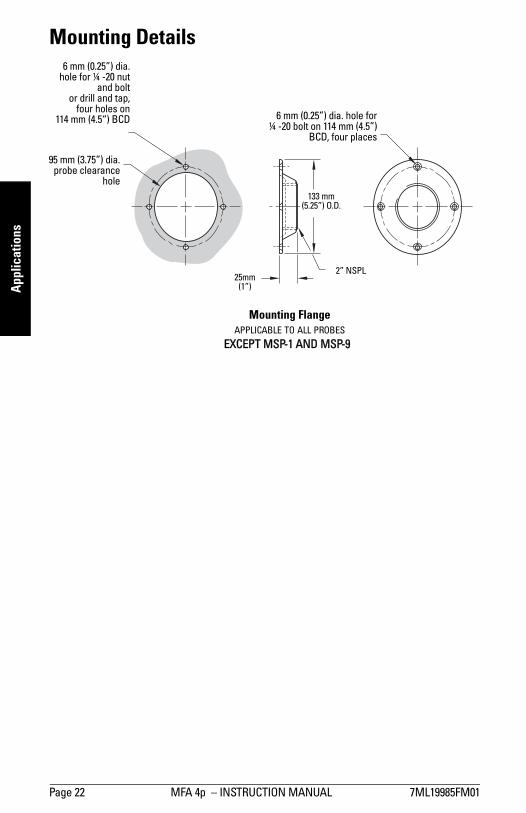
Mounting Details 6 mm (0.25�) dia.hole for ¼ -20 nut
and boltor drill and tap,
four holes on114 mm (4.5�) BCD 6 mm (0.25�) dia. hole for
¼ -20 bolt on 114 mm (4.5�)BCD, four places
95 mm (3.75�) dia.probe clearance
hole
133 mm (5.25�) O.D.
2� NSPL25mm
(1�)
Mounting Flange
APPLICABLE TO ALL PROBES
EXCEPT MSP-1 AND MSP-9
7ML19985FM01 MFA 4p � INSTRUCTION MANUAL Page 23
Ap
plic
atio
ns
Applications
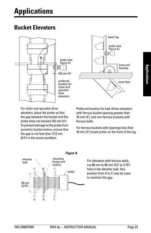
Bucket Elevators
For chain and sprocket drive
elevators, place the probe so that
the gap between the bucket and the
probe does not exceed 102 mm (4").
To prevent damage to the probe from
eccentric bucket motion, ensure that
the gap is not less than 12.5 mm
(0.5") in the worst condition.
Preferred location for belt-driven elevators
with ferrous bucket spacing greater than
76 mm (3"), and non-ferrous buckets with
ferrous bolts.
For ferrous buckets with spacings less than
76 mm (3") locate probe on the front of the leg.
probe (see Figure A)
preferred location for chain and sprocket drive elevators.
down leg
probe (see Figure A)
knee and housing
work floor
102 mm (4")
For elevators with ferrous walls,
cut 88 mm to 95 mm (3.5" to 3.75")
hole in the elevator wall. Any
position from A to C may be used
to maintain the gap.
Figure A
mounting flange and locknut
elevator wall
95 mm (3.75")
probe
A B C

Page 24 MFA 4p � INSTRUCTION MANUAL 7ML19985FM01
Ap
pli
ca
tio
ns
Shafts
These methods are viable if the speed is such that the blades or key will provide the
number of pulses required at a minimum velocity of 1.5 m / minute (5 ft. / minute). In
applications where exposed moving parts are required, safety shields and precautions
should be applied.
Where conditions prevent the sensing of buckets, a belt pulley or paddle mounted on an
exposed shaft end, preferably the tail pulley, may be used.
Belt Conveyors
Potential for damage in each application governs the minimum gap allowable. Maximum
gap for operation is 102 mm (4"), optimum 25 mm to 50 mm (1" to 2").
Screw Conveyors
A ferrous mass added behind the flight of a screw conveyor, where it passes the probe
aids Borderline Operation. This mass must be added for all non-ferrous screws.
probe
shaft
added paddle
safety shield not shown
probe
shaft
key in keyway
102 mm (4�) dia. min.
50 x 50 x 25 mm (2� X 2� X 1") ferrous blocks or spoked wheel
probeprobe
The probe should be located at the idler end
(usually feed end)
Arrows indicate permissible place-
ment range of the probe

7ML19985FM01 MFA 4p � INSTRUCTION MANUAL Page 25
Ap
plic
atio
ns
Non-Ferrous Window
For screw conveyor with trough over 3.1 mm (0.125") thick or for high temperature
applications. The dimensions shown for the base, window, and bracket are the minimum
recommended with tolerances of ± 0.8 mm (0.031"). Use 305, 310, or 316 stainless steel,
brass, or aluminum.
The probe may not touch the window if temperatures are in excess of 60 °C (140 °F) when
using the low temperature probes or 260 °C (500 °F) when using the high temperature
probes.
Bucket Elevator
MINIMUM RECOMMENDED DIMENSIONS SHOWN
PROBE ANDMOUNTING FLANGE
BRACKET
WELD
BASE PLATE
153 mm SQ.(6”)
12.7 mm MAX.(0.5”)
115 mm
115 mm
70 mm
140 mm SQ.
179 mm SQ.
(4.52”)
(4.52”)
(2.75”)(5.5”)
(7”)
WINDOW
CONVEYORHOUSING
6 mm ø (0.25”)CLEARANCE4 HOLES
64 mm ø (3.5”)CLEARANCEHOLE
C
C

Page 26 MFA 4p � INSTRUCTION MANUAL 7ML19985FM01
Ap
pli
ca
tio
ns
Rotating Shaft of Rotary Feeder
Drive Sprocket on Rotary Feeder

7ML19985FM01 MFA 4p - INSTRUCTION MANUAL Page 27
Trou
ble
sho
otin
g
Screw Conveyor Flights
End Bearing on Screw Conveyor
Page 28 MFA 4p � INSTRUCTION MANUAL 7ML19985FM01
Tro
ub
lesh
oo
tiin
g
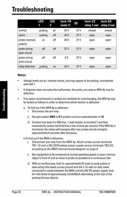
Troubleshooting
Notes:
� Voltage levels are dc, nominal values, and may appear to be pulsing, coincidental
with LED 1.
� If diagnosis does not solve the malfunction, the probe, pre-amp or MFA 4p may be
defective.
� If no spare circuit boards or probes are available for interchanging, the MFA 4p may
be tested as follows in order to determine which section is defective:
a. To find out if the MFA 4p is defective:
i. Disconnect the pre-amp.
ii. Set ppm switch SW2 to X 1 position and turn potentiometer to 15.
iii. Connect one Iead of a 530 ohm, 1 watt resistor to terminal 7 and then
momentarily contact terminal 8 at a rate of once per second. If the MFA 4p is
functional, the relays will energize after two puIses and de-energize
approximately 8 seconds after last pulse.
b.To find out if the RMA is defective:
i. Disconnect pre-amp from the MFA 4p. Attach probe across terminals
TB1 1/2 and a 24V DC(floating) power supply across terminals TB2 3/2,
according to the RMA Interconnectiondiagram on page 8.
ii. Run equipment to be monitored at normal operating speed or pass a ferrous
object in front of and as close to probe as possible at a continuous rate.
iii. With an oscilloscope, look for approximately 6V peak to peak pulses or
alternating hi/lo levels across ground and link 3. Or with an amp meter
connected in series between the RMA and the 24V DC power supply, Iook
for hi/lo levels of approximately 12mA/40mA alternating at the rate of the
passing ferrous objects.
LED 1
LED 2
term 7/8 (note 1)
C8term 1/2 relay 1 out
term 4/5 relay 2 out
normal pulsing on 24 V 27 V closed closed
alarm pulsing off 24 V 27 V open open
probe reversed
polarity
on off 20 V 27 V open open
probe wiring
open circuit
off off 27 V 27 V open open
probe wiring
short circuit
off off 0 V 27 V open open
relay defective pulsing on 24 V 27 V open open
7ML19985FM01 MFA 4p - INSTRUCTION MANUAL Page 29
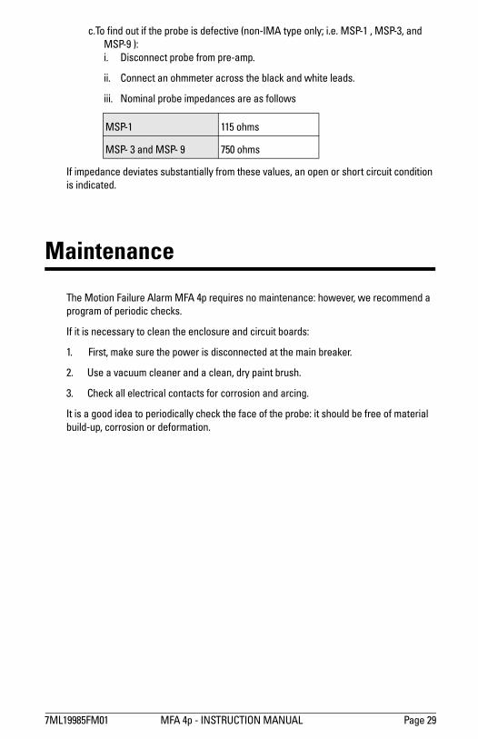
c.To find out if the probe is defective (non-IMA type only; i.e. MSP-1 , MSP-3, and
MSP-9 ):
i. Disconnect probe from pre-amp.
ii. Connect an ohmmeter across the black and white leads.
iii. Nominal probe impedances are as follows
If impedance deviates substantially from these values, an open or short circuit condition
is indicated.
Maintenance
The Motion Failure Alarm MFA 4p requires no maintenance: however, we recommend a
program of periodic checks.
If it is necessary to clean the enclosure and circuit boards:
1. First, make sure the power is disconnected at the main breaker.
2. Use a vacuum cleaner and a clean, dry paint brush.
3. Check all electrical contacts for corrosion and arcing.
It is a good idea to periodically check the face of the probe: it should be free of material
build-up, corrosion or deformation.
MSP-1 115 ohms
MSP- 3 and MSP- 9 750 ohms

Page 30 MFA 4p - INSTRUCTION MANUAL 7ML19985FM01
7ML19985FM01 MFA 4p � INSTRUCTION MANUAL Page 31
Ind
ex
Index
AAmbient Temperature Range 3Applications 23
Automatic Start Delay 11
BBelt Conveyors 24
Bucket Elevator 25
Bucket Elevators 23
CCable length 9Calibration 14
DDimensions
MFA 4p 5Drive Sprocket on Rotary Feeder 26
Dynamic range 2EEnd Bearing on Screw Conveyor 27
IInstallation 4Interconnection 8Interconnection Diagram for the XPP-5 21
LLayout
MFA 4p circuit board 7MMFA 4p
circuit board layout 7operating principles 12
Operation 13
MSP-1 Mini Sensing Probe
dimensions 17
specifications 13
MSP-1, 3, or 9 Probe
interconnection 8MSP-12 Probe with IMA
dimensions 19
interconnection 8MSP-3 High Temperature Probe
dimensions 17
specifications 3MSP-9 stainless steel probe
dimensions 18
specifications 3NNon-Ferrous Window 25
OOperating Principles 12
Operation 13
Output 2Overspeed 15
PPower 2Pre-Amplifier (IMA and RMA) 13
Probe
operating principle 12
Probes
diagrams and details 17
Mounting Details 22
RRepeatability 2Resistive Rating 2Rotating Shaft of Rotary Feeder 26
SScrew Conveyor Flights 27
Screw Conveyors 24
Setpoint adjustment range 2Shafts 24
Signal Generator Interface 16
Specifications 2TTemperature coefficient 2Troubleshooting 28
UUnderspeed 14
WWiring 11
XXPP-5
dimensions 20
interconnection 9interconnection diagram 21
specifications 3

*7ml19985fm01*Rev. 1.2
www.siemens.com/processautomation
Siemens Milltronics Process Instruments Inc.
1954Technology Drive, P.O. Box 4225
Peterborough, ON, Canada K9J 7B1
Tel: (705) 745-2431 Fax: (705) 741-0466
Email: [email protected]
Siemens Milltronics Process Instruments Inc. 2008
Subject to change without prior notice
Printed in Canada