MILLIPORE OM 039 FILTER HOLDER - Liberated … · Operation 1 Slide the neoprene stopper over the...
37
TM 10-6640-225-13&P TECHNICAL MANUAL OPERATOR’S, UNIT AND DIRECT SUPPORT MAINTENANCE MANUAL (INCLUDING REPAIR PARTS AND SPECIAL TOOLS LIST) FOR MILLIPORE OM 039 FILTER HOLDER NSN 6640-00-893-3096 This technical manual is an authentication of the manufacturer’s commercial literature and does not conform with the format and the content requirements normally associated with Army technical manuals. This technical manual does, however, contain all essential information required to operate and maintain the equipment. Approved for public release; distribution is unlimited. HEADQUARTERS, DEPARTMENT OF THE ARMY 28 SEPTEMBER 1990
Transcript of MILLIPORE OM 039 FILTER HOLDER - Liberated … · Operation 1 Slide the neoprene stopper over the...

TM 10-6640-225-13&P
TECHNICAL MANUAL
OPERATOR’S, UNIT ANDDIRECT SUPPORT MAINTENANCE MANUAL
(INCLUDING REPAIR PARTS AND SPECIAL TOOLS LIST)
FOR
MILLIPORE OM 039 FILTER HOLDER
NSN 6640-00-893-3096
This technical manual is an authentication of the manufacturer’s commercial literature anddoes not conform with the format and the content requirements normally associated withArmy technical manuals. This technical manual does, however, contain all essentialinformation required to operate and maintain the equipment.
Approved for public release; distribution is unlimited.
HEADQUARTERS, DEPARTMENT OF THE ARMY28 SEPTEMBER 1990
Read Me
No TOC pdf pg 8 (pg 4) had no OCR (used rules to hit)


TM 10-6640-225-13&P
This technical manual is an authentication of the manufacturer’s commercial literature anddoes not conform with the format and the content requirements normally associated withArmy technical manuals. This technical manual does, however, contain all essentialinformation required to operate and maintain the equipment.
Approved for public release; distribution is unlimited.
SUPPLEMENTARY INTRODUCTORY MATERIAL
1-1. Maintenance Forms and Records.
Department of the Army forms and procedures used for equipment maintenance will be those describedby DA Pam 738-750, The Army Maintenance Management System.
1-2. Reporting Errors and Recommending Improvements.
You can help improve this manual. If you find any mistakes or if you know of a way to improve theprocedures, please let us know. Mail your letters, DA Form 2028 (Recommended Changes toPublications and Blank Forms), or DA Form 2028–2 located in the back of this manual, directly to:Commander, U.S. Army Troop Support Command, ATTN: AMSTR–MCTS, 4300 Goodfellow Blvd.,St. Louis, MO 63120-1798. A reply will be furnished to you.
1–3. Destruction of Army Material to Prevent Enemy Use.
Refer to TM 750-244-3 for instructions covering the destruction of Army Material to prevent enemy use.
1-4. Administrative Storage of Equipment.
a. Placement of equipment in administrative storage should be for short periods of time when ashortage of maintenance effort exists. Items should be in mission readiness within 24 hours or within thetime factors as determined by the directing authority. During the storage period appropriate maintenancerecords will be kept.
b. Before placing equipment in administrative storage, current preventive maintenance checks andservices should be completed. Shortcomings and deficiencies should be corrected, and ail modificationwork orders (MWO’s) should be applied.
c. Storage site selection. inside storage is preferred for items selected for administrative storage. Ifinside storage is not available, trucks, vans, conex containers and other containers may be used.
i/(ii Blank)


Operation and
Maintenance Instructions
O M 0 3 9
Hydrosol Stainless 47mm Filter HolderCat. No. XX20 04720
Function
Vacuum filtering liquids for analysis of particulate or biological contamination retained on the filtersurface, or to produce small quantities or ultraclean filtrate. Sterile procedures require asepticallyinstalling a sterile filter in the separately sterilized holder.
M I L L I P O R E
1

Fig. 1 Filter Holder Components
Replacement Parts(1) Funnel & locking ring assembly(2) Locking ring gasket, Teflon 5/pk(3) Locking ring(4) Nylon Iockwheels, set with wrench(5) Filter support screen, stainless(6) Support screen gasket, Teflon 25pk(7) Base with screen, gasket & stopper(8) #8 neoprene stopper, 3/8” hole 5/pk(9) Grounding screw(10) Hydrosol grounding lead (not shown
AccessoriesFunnel & locking ring assembly, 100mlVacuum filtering flask, I literVacuum/pressure pump, 115V, 60H2Vacuum/pressure pump, 220V, 50HzVacuum/pressure pump, 100V, 50/60HzFilter holder Hydrosol manifold, 6-placeFilter holder Hydrosol manifold, 3-pIaceFilter holder PVC manifold 3–placeVacuum hose Silicone 1 4m (4.5)Filter forceps, stainless, smooth--tip
2
Cat. No.XX20 047 04XX40 047 14XX20 047 01XX20 047 07XX20 047 08XX20 047 03XX20 047 02XX20 047 18
XX63 001 21XX10 047 05XX55 000 00XX55 220 50XX55 100 00XX25 047 00XX25 047 35XX26 047 35XX71 000 04XX62 000 06

Operation
1 Slide the neoprene stopper over the holder outlet, if it is not already in place. Remove the funnel fromthe base by turning the locking ring 1/4 turn, and rest the funnel assembly on its side on a cleansurface. Do not stand it upright, as this may soil the funnel rim or the sealing edge of the funnel outlet.
2 Seat the stopper and base firmly in the neck of the filtering flask. The filter support screen and itsunderlying gasket should be in place in the top of the base, with the screen flat and flush with the basetop (see Disassembly and Cleaning for instructions on removing the screen and gasket).
3 With smooth-tip forceps, center a 47mm diameter Millipore filter on the screen (Fig. 2), with thegridded side up if a gridded filter is being used for later statistical counting procedures.
4 If a prefilter is required to prevent filter plugging in obtaining a desired filtrate, place a 35mm diameterMillipore depth prefilter disc exactly centered on top of the 47mm final filter. Centering must becarefully done, so that the prefilter edge will not lie under the sealing rim of the filter holder funnel.
Fig. 2 Center filter accurately on support screen. Use forceps to avoid contamination or damage tof i l te r .
5 Without touching the inside of the funnel, and without disturbing the filter (or prefilter), place the funnelon the holder base so that the nylon wheels in the locking ring are in the base slots (Fig. 3). Turn thelocking ring to the right until tight, sealing the funnel to the base.
6 If a filtering manifold is used, place an assembled holder and filter in all manifold positions, or seal offunused positions with unperforated stoppers unless they can be closed by independent valves.
3

Fig. 3 Nylon Iockwheels fit into slots in base; a quarter turn of locking ring then seals funnel to base.
7 Connect the filtering flask or manifold to the vacuum source, with silicone rubber tubing, pour thesample into the funnel and apply vacuum to filter the sample.
CAUTION
If the vacuum source is a dry–air pump, such as Millipore Cat. No.XX55 000 00, liquids should not be allowed to enter the pump intake. Thesimplest way to guard against this is to install a second side-arm flaskbetween filtering flask (or manifold) and the pump as shown in Figure 4.
Fig. 4 Second side-arm flask connected in series keeps liquid droplets or water vapor out of pump.
8 When the sample level has lowered to the neck of the funnel, rinse down the funnel walls with about30 ml of filtered water or appropriate solvent, not letting this liquid strike the filter surface. This flushesresidue from the walls, and helps to secure a uniform contaminant distribution on the filter surface forstatistical counting. In microbiological tests, the rinse fluid must be sterile and buffered. In other tests,a filtered jet from the Millipore Solvent Filtering Dispenser can be used.
9 As soon as all sample and flushing fluid has passed through the filter, shutoff the vacuum and gentlyrock the holder assembly to break the stopper seal and vent the flask vacuum. Rotate the locking ringto the left until it stops, releasing the funnel from the base. Lift off the funnel and transfer the filter withsmooth–tip forceps to a clean petri dish for visual particle counting, or to a prepared media pad or agar
4

plate in a sterile petri dish for microbial contaminant culturing. Detaileddescribed in Millipore publications dealing with specific applications.
Sterile Procedures
analytical procedures are
This filter holder may not be autoclave with a filter in place. For bacteriological analyses, separatelysterilize the holder with dry heat or by autoclaving the disassembled funnel and base for 15-20 minutes at
121°C (15 psig), then reassemble it aseptically with a sterile Millipore filter.
In sterilizing or autoclaving, the funnel and base should first be wrapped with lint-free Kraft paper orTyvek, then secured with tape to close the openings and protect the filter support area. Sincetemperatures are known to vary from point to point in an autoclave, and may differ significantly from theautoclave setting, they should be checked occasionally with a maximum registering thermometer.
Avoid using autoclave steam containing amines, which are often added to boiler feed water to preventscale. They may contaminate liquids that come in contact with autoclave surfaces.
Procedure for Flammable Liquids
1
2
3
WARNING
When flammable liquids are filtered through a membrane, high staticcharges may be generated. The possibility of a fire, or explosion that mightensue from this static electricity, can be prevented by grounding the filterholder in the manner explained below.
A Hydrosol Grounding Lead (Fig. 5) is contained with your Millipore Hydrosol Holder. It consists of alength of #20 AWG wire cable fitted at one end with a spade-lug, and an alligator clip at the other. Anadditional 4 ft. length of this wire cable is soldered to the alligator clip.
Fig. 5 Grounding Hydrosol Holder
To assure that the grounding lead(s) will perform as manufactured, an electrical continuity checkshould be made prior to connecting to the holder.
If the continuity check proves acceptable, connect the spade-lug to the grounding screw located onthe bottom of the Hydrosol base.
5

4 Prepare the filter holder with a filter as described in steps 1–6 shown on page 3. and 4.
5 Fasten the alligator clip firmly to the funnel lip, and making a good electrical connection, attach the 4 ft.length of the grounding lead to a known good ground, such as a copper or similar conductive metalwater-pipe.
6 Perform an electrical continuity check on the connected grounding system as set up prior toproceeding to the next step. Make sure that both base and funnel are at ground potential.
7 If the check shows acceptable conduction within the systems proceed to step 7 (page 4) and carry onwith the filtration operation.
CAUTION
Filtration of flammable liquids should be carried out within a fume hood,fitted and set up with the appropriate safety measures for this type ofoperation. The vacuum pump, if not explosion proof, should be placedoutside of and away from the fume hood opening.
Disassembly and Cleaning
Immediately after use, the filter support screen and gasket should be removed from the holder base, and
all components cleaned with a sponge, hot water and a non–abrasive cleanser. Never use steel wool orabrasive materials on any part of the holder.
1 The filter support screen is held tightly in the base by friction. To remove it, hold the base upside downand slightly tilted and strike its edge sharply against a hard, clean surface. Because the screen caneasily be damaged, never use a sharp or pointed instrument to pry it from the base. The small Teflongasket can be lifted from the screen recess with forceps, and carefully set aside.
2 A stiff bristled brush is useful in removing traces of stubborn residue, but do not use a brush on thefilter support screen. It can break the screen mesh and cause a ruptured filter. A pipe cleaner withdete; gent solution is helpful in cleaning the inside of the holder outlet tube.
3 After cleaning, thoroughly rinse the components with clean water and air dry. Do not wipe with paperor cloth, which will leave traces of fibers or lint. In rinsing, take special care to flush out the area underthe top of the locking ring. Carefully inspect the components for signs of damage, reassemble thebase with the Teflon gasket underneath the screen (which is always installed with its screen surfaceup), wrap the funnel and base separately with Kraft paper or Tyvek, autoclave, if desired, and store forlater use. Over an extended period of use, or after filtering heavily contaminated liquids, the flat Teflongasket under the top of the locking ring may accumulate dirt that will interfere with the holder’s sealingaction. To remove it for special cleaning or replacement, proceed as follows.
4 Invert the funnel and locking ring assembly (without base), and place it on a clean surface. Using theAllen wrench supplied, slightly loosen the two set screws in the locking ring.
5 Remove the nylon Iockwheels from the locking ring and set them aside, allowing the ring to restagainst the bottom of the funnel. Three set screws in the sealing collar of the funnel will now beaccessible.
6

6 With a 9164” (approximately 3.57mm) Allen wrench (not supplied), loosen these set screws untilabout 1/4” (6mm) of each is exposed. The sealing collar can now be lifted from the end of the funnel,allowing the locking ring and flat Teflon gasket to be removed.
7 Inspect the gasket and the inner surface of the locking ring for injury or dirt, and clean themthoroughly. Small particles of imbedded grit can be dislodged from the Teflon gasket without injuringit, but the gasket should be replaced if it is damaged or badly distorted.
8 To reassemble, place the clean gasket inside the locking ring and slip the ring, open side up, over theend of the funnel. Then replace the funnel collar and tighten its setscrews, making sure that they restin the groove of the funnel. When properly positioned, the end of the funnel projects approximately1/16“ (1.6mm) beyond the face of the collar.
9 Replace the Iockwheels inside the locking ring, tightening their holding screws until each wheel willnot turn. The wheels should be positioned to present smooth, round bearing surfaces to the lockingcams on the underside of the holder base. The set screws on the outside of the locking ring can nowbe tightened to keep the Iockwheel holding screws from loosening during use.
10 If a flat spot develops in either Iockwheel after a period of use, both wheels should be rotated to newpositions, or replaced if necessary.
Specifications
Materials Stainless funnel, base and filter support screen, anodized aluminum locking ring, nylon lockingwheels, Teflon gaskets, neoprene stopper.
Filter Size 47mm diameter
Filter Area Approximately 9.6 cm2. The filtration area of a gridded Millipore filter in this holder contains100 grid squares.
Depth Prefilter Size 35mm diameter
Funnel Capacity 650ml
Pressures Vacuum only
Connections #8 perforated stopper placed over outlet tube mounts in standard –liter filtering flask orMillipore filtering manifolds (available separately).
Dimensions 114mm (41/2”) diameter, 229mm (9”) high
Technical Assistance
To obtain technical assistance, call our Technical Services Department toll-free at 800-225-1380.
In Western States 800-632-2708
In Massachusetts 617-275-9200
In Canada 800-2684881
7

In Puerto Rico 809-739-8485
In Alaska and Hawaii 415-952-9200
Outside of U.S.A., contact the nearest Millipore office or agent listed in the Millipore Catalogue.
Millipore is a registered trademark of Millipore Corporation.
Teflon and Tyvek are registered trademarks of El. Dupont deNemours Co.
11567 Printed in U.S.A. 5/75 REV. 6/85
MILLIPORE
8

TM 10-6640-225-13&P
APPENDIX A
R E F E R E N C E S
A–1. Scope. This appendix contains all forms, pamphlets and technical manuals referenced in boththe Air mobile and Semitrailer mounted Laboratories.
A–2. Forms.
Recommended Changes to Publications . . . . . . . . . . . . . . . . . . . . . . . . . . . . . . . . . . . DA Form 2028DA Form 2028–2
Quality Deficiency Report . . . . . . . . . . . . . . . . . . . . . . . . . . . . . . . . . . . . . . . . . . . . . . . . . SF368Equipment inspection and Maintenance Work Sheet . . . . . . . . . . . . . . . . . . . . . . . . . . DA Form 2404Hand Receipts . . . . . . . . . . . . . . . . . . . . . . . . . . . . . . . . . . . . . . . . . . . . . . . . . . . . . . . . DA Form 2062
A-3. Field Manuals.
Petroleum Testing Facilities:Laboratories and Kits . . . . . . . . . . . . . . . . . . . . . . . . . . . . . . . . . . . . . . . . . . . . . . . . . . .. FM10-72
Inspecting and Testing Petroleum Products . . . . . . . . . . . . . . . . . . . . . . . . . . . . . . . . . . . . . FM 10-70
ASTM Test Method Supplement to.... . . . . . . . . . . . . . . . . . . . . . . . . . . . . . . . . . . . FM 10-92C1/C2
A-4. Technical Manuals.
Atlas-Copco Compressor . . . . . . . . . . . . . . . . . . . . . . . . . . . . . . . . . . . . . . . TM10-4310-392-13&PAlcor Jet Fuel Thermal Oxidation Tester Operating
and Maintenance Manual . . . . . . . . . . . . . . . . . . . . . . . . . . . . . . . . . . . . TM 10-6635-210-13&P
Bacharach Gas Alarm and Calibration Data . . . . . . . . . . . . . . . . . . . . . . . . . TM 10-6665-297-13&PBrother Portable Typewriter . . . . . . . . . . . . . . . . . . . . . . . . . . . . . . . . . . . . . . TM 10–7430–218–13&PChemtrix Field Ph Meter . . . . . . . . . . . . . . . . . . . . . . . . . . . . . . . . . . . . . . . . TM10-6630-237–13&PElkay Manufacturing 30 GPH Cooler . . . . . . . . . . . . . . . . . . . . . . . . . . . . . . TM10-4130-240-13&PEmcee Micro-Separometer . . . . . . . . . . . . . . . . . . . . . . . . . . . . . . . . . . . . . . TM 10-6640-222-13&PFoxboro Pressure Recording Gauge . . . . . . . . . . . . . . . . . . . . . . . . . . . . . . . TM 10-6685-365-13&P
Gammon Aqua Glo Water Detector . . . . . . . . . . . . . . . . . . . . . . . . . . . . . . . TM10-6640-221–13&PGammon Mini Monitor Fuel Sampling Kit . . . . . . . . . . . . . . . . . . . . . . . . . . . TM 10-6630-230-13&P
Jelrus Burn-Out Furnace . . . . . . . . . . . . . . . . . . . . . . . . . . . . . . . . . . . . . . . TM 10-6640-231-13&PKoehler Cleveland Open Tester . . . . . . . . . . . . . . . . . . . . . . . . . . . . . . . . . . TM 10-6630-236-13&P
Koehler Cloud and Pour Point Chamber . . . . . . . . . . . . . . . . . . . . . . . . . . . . TM 10-6630-238-13&P
Koehler Copper Strip Corrosion Bomb Bath . . . . . . . . . . . . . . . . . . . . . . . . . TM10-6640-220-13&PKoehler Distillation Apparatus . . . . . . . . . . . . . . . . . . . . . . . . . . . . . . . . . . . . TM10-6330-233-13&PKoehler Dropping Point Apparatus . . . . . . . . . . . . . . . . . . . . . . . . . . . . . . . . TM10-6635-211-13&PKoehler Electric Pensky-Martins Tester . . . . . . . . . . . . . . . . . . . . . . . . . . . . TM 10-6630-230-13&PKoehler Foaming Characteristics Determination Apparatus . . . . . . . . . . . . . TM 10-6640-228-13&PKoehler Kinematic Viscosity Bath . . . . . . . . . . . . . . . . . . . . . . . . . . . . . . . . . TM 10-6630-239-13&P
Koehler Tag Closed Cup Flash Tester . . . . . . . . . . . . . . . . . . . . . . . . . . . . . TM 10-6630-235-13&P
Lab-Line Explosion Proof Refrigerator . . . . . . . . . . . . . . . . . . . . . . . . . . . . . TM 10-6640-219-13&PLily Freezer . . . . . . . . . . . . . . . . . . . . . . . . . . . . . . . . . . . . . . . . . . . . . . . . . . TM 10-6640-234-13&P
Mllipore OM 39 Filter Holder . . . . . . . . . . . . . . . . . . . . . . . . . . . . . . . . . . . . . TM10-6640-225-13&PMillipore Vacuum Pump . . . . . . . . . . . . . . . . . . . . . . . . . . . . . . . . . . . . . . . . . TM 10-6640-217-13&POhaus Harvard Trip Balance . . . . . . . . . . . . . . . . . . . . . . . . . . . . . . . . . . . . . TM 10-6670-278-13&PPrecision Gas-Oil Distillation Test Equipment . . . . . . . . . . . . . . . . . . . . . . . TM 10-6630-219-13&Pprecision General purpose Water Bath . . . . . . . . . . . . . . . . . . . . . . . . . . . . TM 10-6640-229-13&P
A-1

TM 10-6640-225-13&P
Precision High Temperature Bronze Block Gum Bath . . . . . . . . . . . . . . . . TM 10-6630-234-13&PPrecision General Purpose Ovens . . . . . . . . . . . . . . . . . . . . . . . . . . . . . . . TM 10-6640–218–13&PPrecision Heater Instruction Manual and Parts List . . . . . . . . . . . . . . . . . . TM 10-6640-223-13&PPrecision Oxidation Stability Bath . . . . . . . . . . . . . . . . . . . . . . . . . . . . . . . . TM 10-6640-232-13&PPrecision Pensky-Martens Flash Testers . . . . . . . . . . . . . . . . . . . . . . . . . . TM 10-6630-231-13&PPrecision Reid Vapor Pressure Bath . . . . . . . . . . . . . . . . . . . . . . . . . . . . . . TM 10-6640–226-13&PPrecision Slo-Speed Stirrer . . . . . . . . . . . . . . . . . . . . . . . . . . . . . . . . . . . . TM 10-6640–224-13&PPrecision Universal Centrifuge . . . . . . . . . . . . . . . . . . . . . . . . . . . . . . . . . . TM 10-6640-230-13&PPrecision Universal Penetrometer . . . . . . . . . . . . . . . . . . . . . . . . . . . . . . . . TM 10-6640-228-13&PSargent–Welch Vacuum Pump . . . . . . . . . . . . . . . . . . . . . . . . . . . . . . . . . . TM 10-4310-391-13&PSartorious Analytical Balance . . . . . . . . . . . . . . . . . . . . . . . . . . . . . . . . . . . TM 10-6670-277-13&PScotsman Cuber . . . . . . . . . . . . . . . . . . . . . . . . . . . . . . . . . . . . . . . . . . . . . TM 10-6640-227-13&PSoltec VOM-Multimeter . . . . . . . . . . . . . . . . . . . . . . . . . . . . . . . . . . . . . . . . TM 10-6625-3127-13&PTeel Self–Priming Centrifugal Pump . . . . . . . . . . . . . . . . . . . . . . . . . . . . . . TM 10-6640-217-13&PTeel Submersible Pump . . . . . . . . . . . . . . . . . . . . . . . . . . . . . . . . . . . . . . . TM 104320-320-13&PTexas Instrument TI–5030II Calculator . . . . . . . . . . . . . . . . . . . . . . . . . . . . TM 10–7420–210–13&P
A-5. Pamphlets .
The Army Maintenance Management System (TAMMS) . . . . . . . . . . . . . . . . . . . . . DA Pam 738–750
A-6. Miscellaneous Publications.
The Army Integrated Publishing and Printing Program . . . . . . . . . . . . . . . . . . . . . . . . . . . . . AR 25-30Laboratory, Airmobile, Aviation Fuel . . . . . . . . . . . . . . . . . . . . . . . . . . . . . . . . . . . MIL–L–52733A(ME)Apparatus, instruments, Chemicals, Furniture, and Supplies for industrial,
Clinical, College and Government Laboratories . . . . . . . . . Fisher Scientific Laboratories CatalogPetroleum–Petrochemical Testing Equipment . . . . . . . . . . . . . . . . . . . . . Precision Scientific Catalog
A - 2

TM 10-6640-225-13&P
APPENDIX B
MAINTENANCE ALLOCATION CHART
Sect ion I . INTRODUCTION
B-1 . Genera l .
a. This section provides a general explanation of all maintenance and repair functions authorized atvarious maintenance categories.
b. The Maintenance Allocation Chart (MAC) in Section II designates overall authority andresponsibility for the performance of maintenance functions on the identified end item or component. Theapplication of the maintenance functions to the end item or component will be consistent with thecapacities and capabilities of the designated maintenance categories.
c. Section Ill lists the tooIs and test equipment (both special tools and common tool sets) required foreach maintenance function as referenced from Section Il.
d. Section IV contains supplemental instructions and explanatory notes for a particular maintenancefunction.
B-2. Maintenance Functions. Maintenance functions will be limited to and defined as follows:
a. Inspect. To determine the serviceability of an item by comparing its physical, mechanical, and/orelectrical characteristics with established standards through examination (e.g., by sight, sound, or feel).
b. Test. To verify serviceability by measuring the mechanical, pneumatic, hydraulic, or electricalcharacteristics of an item and comparing those characteristics with prescribed standards.
c. Service. Operations required periodically to keep an item in proper operating condition, i.e., toclean (includes decontaminate, when required), to preserve, to drain, to paint, or to replenish fuel,lubricants, chemical fluids, or gases.
d. Adjust. To maintain or regulate, within prescribed limits, by bringing into proper or exact position,or by setting the operating characteristics to specified parameters.
e. Align. To adjust specified variable elements of an item to bring about optimum or desiredperformance.
f. Calibrate. To determine and cause corrections to be made or to be adjusted on instruments ortest, measuring, and diagnostic equipments used in precision measurement. Consists of comparisons oftwo instruments, one of which is a certified standard of knob accuracy, to detect and adjust anydiscrepancy in the accuracy of the instrument being compared.
g. Remove/Install. To remove and install the same item when required to perform service or othermaintenance functions. Install may be the act of emplacing, seating, or fixing into position a spare, repairpart, or module (component or assembly) in a manner to allow the proper functioning of an equipment orsystem.
h. Replace. To remove an unserviceable item and install a serviceable counterpart in its place.“Replace” is authorized by the MAC and is shown as the third position code of the SMR code.
B-1
TM 10-6640-225-13&P
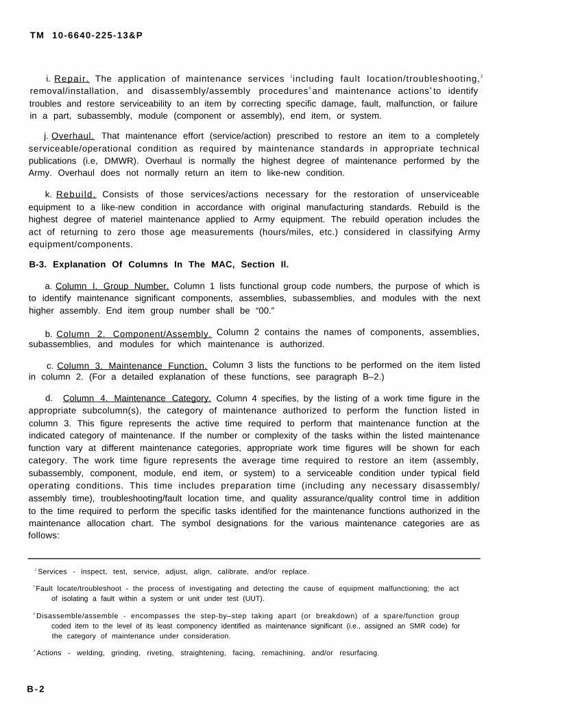
i. Repair . The application of maintenance services 1including fault location/troubleshooting, 2
removal/installation, and disassembly/assembly procedures3 and maintenance actions4 to identifytroubles and restore serviceability to an item by correcting specific damage, fault, malfunction, or failurein a part, subassembly, module (component or assembly), end item, or system.
j. Overhaul. That maintenance effort (service/action) prescribed to restore an item to a completelyserviceable/operational condition as required by maintenance standards in appropriate technicalpublications (i.e, DMWR). Overhaul is normally the highest degree of maintenance performed by theArmy. Overhaul does not normally return an item to like-new condition.
k. Rebui ld. Consists of those services/actions necessary for the restoration of unserviceableequipment to a like-new condition in accordance with original manufacturing standards. Rebuild is thehighest degree of materiel maintenance applied to Army equipment. The rebuild operation includes theact of returning to zero those age measurements (hours/miles, etc.) considered in classifying Armyequipment/components.
B-3. Explanation Of Columns In The MAC, Section Il.
a. Column I. Group Number. Column 1 lists functional group code numbers, the purpose of which isto identify maintenance significant components, assemblies, subassemblies, and modules with the nexthigher assembly. End item group number shall be “00.”
b. Column 2. Component/Assembly. Column 2 contains the names of components, assemblies,subassemblies, and modules for which maintenance is authorized.
c. Column 3. Maintenance Function. Column 3 lists the functions to be performed on the item listedin column 2. (For a detailed explanation of these functions, see paragraph B–2.)
d. Column 4. Maintenance Category. Column 4 specifies, by the listing of a work time figure in theappropriate subcolumn(s), the category of maintenance authorized to perform the function listed incolumn 3. This figure represents the active time required to perform that maintenance function at theindicated category of maintenance. If the number or complexity of the tasks within the listed maintenancefunction vary at different maintenance categories, appropriate work time figures will be shown for eachcategory. The work time figure represents the average time required to restore an item (assembly,subassembly, component, module, end item, or system) to a serviceable condition under typical fieldoperating conditions. This time includes preparation time (including any necessary disassembly/assembly time), troubleshooting/fault location time, and quality assurance/quality control time in additionto the time required to perform the specific tasks identified for the maintenance functions authorized in themaintenance allocation chart. The symbol designations for the various maintenance categories are asfollows:
1 Services - inspect, test, service, adjust, align, calibrate, and/or replace.
2 Fault locate/troubleshoot - the process of investigating and detecting the cause of equipment malfunctioning; the actof isolating a fault within a system or unit under test (UUT).
3 Disassemble/assemble - encompasses the step-by–step taking apart (or breakdown) of a spare/function groupcoded item to the level of its least componency identified as maintenance significant (i.e., assigned an SMR code) forthe category of maintenance under consideration.
4 Actions - welding, grinding, riveting, straightening, facing, remachining, and/or resurfacing.
B - 2

TM 10-6640-225-13&P
C . . . . . . . . . . . . . . . . . . . . .
O . . . . . . . . . . . . . . . . . . . .
F . . . . . . . . . . . . . . . . . . . . .
H . . . . . . . . . . . . . . . . . . . . .
D . . . . . . . . . . . . . . . . . . . . .
Operator/Crew
Unit Maintenance
Direct Support Maintenance
General Support Maintenance
Depot Maintenance
e. Column 5. Tools and Equipment. Column 5 specifies, by code, those common tool sets (notindividual tools) and special tools, TMDE, and support equipment required to perform the designatedfunction.
f.order,
B-4.
a.
Column 6. Remarks. This column shall, when applicable, contain a letter code, in alphabeticwhich shall be keyed to the remarks contained in section IV.
Explanation Of Columns In Tool And Test Equipment Requirements, Section iii.
Column I. Reference Code. The tool and test equipment reference code correlates with a codeused in the MAC, section II, column S.
b. Column 2. Maintenance Category. The lowest category of maintenance authorized to use the toolor test equipment.
c.
d.
e.
B-5.
a.
b.
Column 3. Nomenclature. Name or identification of the tool or test equipment.
Column 4. National Stock Number. The National stock number of the tool or test equipment.
Column 5. Tool Number. The manufacturer’s part number.
Explanation Of Columns In Remarks, Section IV.
Column I. Reference Code. The code recorded in column 6, Section il.
Column 2. Remarks. This column lists information pertinent to the maintenance function beingperformed as indicated in the MAC, section Il.
Section I l . MAINTENANCE ALLOCATION CHART
(1) (2) (3) (4) (5) (6)GROUP COMPONENT/ MAINTENANCE MAINTENANCE LEVEL TOOLS AND
NUMBER ASSEMBLY FUNCTION UNIT DS GS DEPOT EQUIPMENT REMARKSC O F H D
FILTER HOLDER INSPECT 0.1REPLACE 0.1REPAIR 0.3 A
B - 3

TM 10-6640-225-13&P
Section I l l . TOOL AND TEST EQUIPMENT REQUIREMENTS
F O R
MAINTENANCE ALLOCATION CHART
NOT APPLICABLE
Section IV. REMARKS
REFERENCECODE REMARKS
A Repairs limited to replacement of parts listed in manual
B - 4

TM 10-6640-225-13&P
APPENDIX C
COMPONENTS OF END ITEM AND BASIC ISSUE ITEMS LISTS
Section I. INTRODUCTION
C - 1 . S c o p e .
This appendix lists components of end item and basic issue items for the OM 039 Filter Holder to help youinventory items required for safe and efficient operation.
C-2 . Genera l .
The Components of End Item and Basic Issue Items Lists are divided into the following sections:
a. Section II. Components of End Item. This listing is for informational purposes only, and is notauthority to requisition replacements. These items are part of the end item, but are removed andseparately packaged for transportation or shipment. As part of the end item, these items must be with theend item whenever it is issued or transferred between property accounts. Illustrations are furnished toassist you in identifying the items.
b. Section III. Basic Issue Items. These are the minimum essential items required to place the OM039 Filter Holder in operation, to operate it, and to perform emergency repairs. Although shippedseparately packaged, Bll must be with the shelter during operation and whenever it is transferredbetween property accounts. The illustrations will assist you with hard–to–identify items. This manual isyour authority to request/requisition replacement Bll, based on TOE/MTOE authorization of the end item.
C–3. Explanation of Columns.
The following provides an explanation of columns found in the tabular listings:
a. Column (1) – Illustration Number (Illus Number). This column indicates the number of theillustration in which the item is shown.
b. Column (2) – National Stock Number. Indicates the National stock number assigned to the itemand will be used for requisitioning purposes.
c. Column (3) – Description. Indicates the Federal item name and, if required, a minimumdescription to identify and locate the item. The last line for each item indicates the CAGEC (inparentheses) followed by the part number.
d. Column (4) – Unit of Measure (U/M). Indicates the measure used in performing the actualoperational/maintenance function. This measure is expressed by a two-character alphabeticalabbreviation (e.g., ea, in, pr).
e. Column (5) – Quantity required (QTY RQR). Indicates the quantity of the item authorized to beused with/on the equipment.
C-1
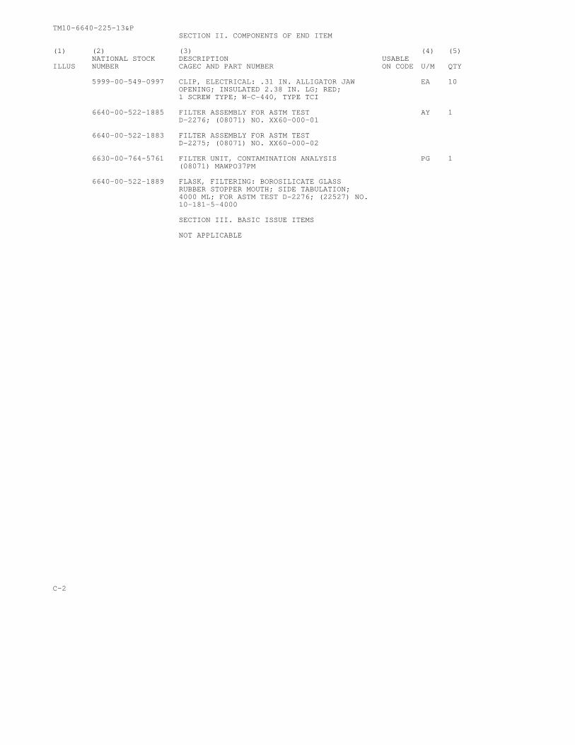
TM10-6640-225-13&PSECTION II. COMPONENTS OF END ITEM
(1) (2) (3) (4) (5)NATIONAL STOCK DESCRIPTION USABLE
ILLUS NUMBER CAGEC AND PART NUMBER ON CODE U/M QTY
5999-00-549-0997 CLIP, ELECTRICAL: .31 IN. ALLIGATOR JAW EA 10OPENING; INSULATED 2.38 IN. LG; RED;1 SCREW TYPE; W-C-440, TYPE TCI
6640-00-522-1885 FILTER ASSEMBLY FOR ASTM TEST AY 1D-2276; (08071) NO. XX60-000-01
6640-00-522-1883 FILTER ASSEMBLY FOR ASTM TESTD-2275; (08071) NO. XX60-000-02
6630-00-764-5761 FILTER UNIT, CONTAMINATION ANALYSIS PG 1(08071) MAWPO37PM
6640-00-522-1889 FLASK, FILTERING: BOROSILICATE GLASSRUBBER STOPPER MOUTH; SIDE TABULATION;4000 ML; FOR ASTM TEST D-2276; (22527) NO.10-181-5-4000
SECTION III. BASIC ISSUE ITEMS
NOT APPLICABLE
C-2

TM 10-6640-225-13&P
APPENDIX D
ADDITIONAL AUTHORIZATION L IST
NOT APPLICABLE
D-1/(D-2 Blank)


TM 10-6640-225-13&P
APPENDIX E
EXPENDABLE/DURABLE SUPPLIES AND MATERIALS LIST
Section I . INTRODUCTION
E–1. Scope. This listing is for informational purposes only and is not authority to requisition the listeditems. These items are authorized to you by CTA 50-970, Expendable/Durable Items (except medical,class V, repair parts, and heraldic items).
E–2. Explanation of Columns.
a. Colurmn (1) – Item Number. This number is assigned to the entry in the listing and is referenced inthe narrative instructions to identify the material (e.g., Use cleaning compound, item 5, appendix C).
b. Column (2) - Level. This column identifies the lowest level of maintenance that requires the listeditem.
C – Operator/Crew
O – Unit Maintenance
F – Direct Support Maintenance
H – General Support Maintenance
c. Column (3) – National Stock Number. This is the National stock number assigned to the item; useit to request or requisition the item.
d. Column (4) – Description. Indicates the Federal item name, and, if required, a description toidentify the item. The last line for each item indicates the Commercial and Government Entity Code(CAGEC) in parentheses followed by the part number.
e. Column (5) – Unit of Measure (U/M). Indicates the measure used in performing the actualmaintenance function. This measure is expressed by a two-character alphabetical abbreviation (e.g.,EA, IN, PR). If the unit of measure differs from the unit of issue, requisition the lowest unit of issue that willsatisfy your requirements.
Section I l . EXPENDABLE/DURABLE SUPPLIES AND MATERIALS LIST
(1) (2) (3) (4) (5)Item National Stock Description U/M
Number Level Number
C 6640-00-985-2099 DISK, FILTERING, MICROPOROUS: AEROSOL HDAND HYDROSOL; 25mm DIA.; 100’s FORASTM TEST D-2276 (08071) HAWP-025-00
C 6640-00-967-0501 DISK, FILTERING, MICROPOROUS: PLAIN; HDAEROSOL; 47mm DIA.;100’s FOR ASTMTEST D-2276; (08071) AAWP-047-00
C 6145-00-299-5186 WIRE, ELECTRICAL: COPPER; SOFT MATER- LBIAL; SOLID CONDUCTOR; RED; No. 16 AWG;UNCOATED; 875.20 OHMS PER MILE-lb;
20°C QQ-W-343, TYPE S
E-1/(E-2 Blank)


TM 10-6640-225-13&P
By Order of the Secretary of the Army:CARL E. VUONO
General, United States ArmyChief of Staff
Official:
THOMAS F. SIKORABrigadier General, United States Army
The Adjutant General
DISTRIBUTION:To be distributed in accordance with DA Form 12–21A, Operator, Unit and Direct SupportMaintenance requirements for Laboratory, Air Mobile, Aviation Fuel and Laboratory,Petroleum, MTD
* U.S. GOVERNMENT PRINTING OFFICE 1991 554-123/20143


P I N : 0 4 6 5 7 4 - 0 0 0

This fine document...
Was brought to you by me:
Liberated Manuals -- free army and government manuals
Why do I do it? I am tired of sleazy CD-ROM sellers, who take publicly available information, slap “watermarks” and other junk on it, and sell it. Those masters of search engine manipulation make sure that their sites that sell free information, come up first in search engines. They did not create it... They did not even scan it... Why should they get your money? Why are not letting you give those free manuals to your friends?
I am setting this document FREE. This document was made by the US Government and is NOT protected by Copyright. Feel free to share, republish, sell and so on.
I am not asking you for donations, fees or handouts. If you can, please provide a link to liberatedmanuals.com, so that free manuals come up first in search engines:
<A HREF=http://www.liberatedmanuals.com/>Free Military and Government Manuals</A>
– SincerelyIgor Chudovhttp://igor.chudov.com/
– Chicago Machinery Movers