Millimeter Wave Frequency Extenders
14
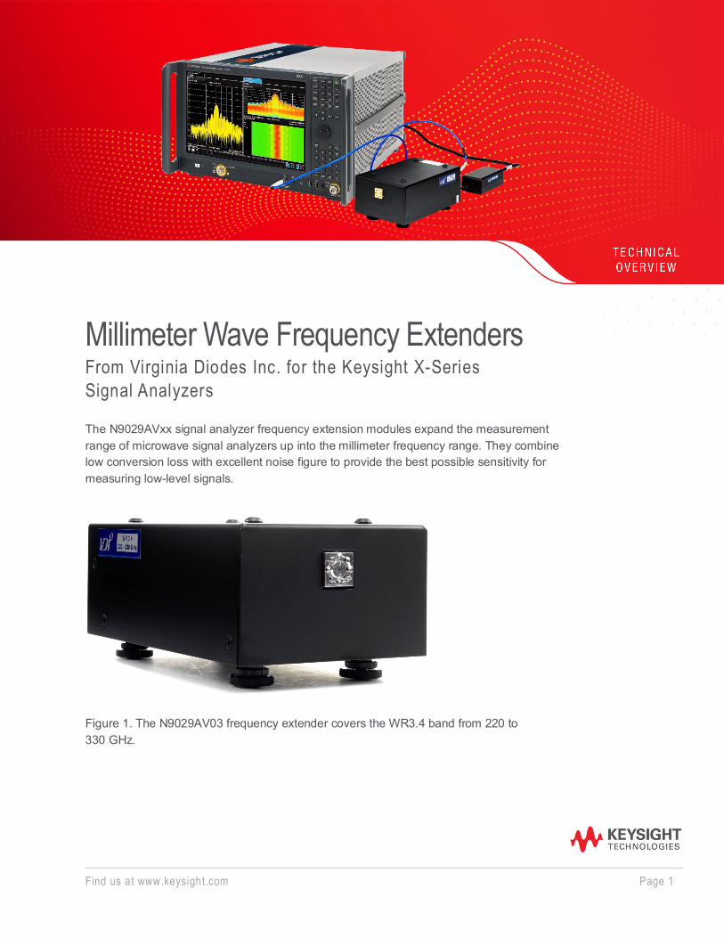
Find us at www.keysight.com Page 1 Millimeter Wave Frequency Extenders From Virginia Diodes Inc. for the Keysight X-Series Signal Analyzers The N9029AVxx signal analyzer frequency extension modules expand the measurement range of microwave signal analyzers up into the millimeter frequency range. They combine low conversion loss with excellent noise figure to provide the best possible sensitivity for measuring low-level signals. Figure 1. The N9029AV03 frequency extender covers the WR3.4 band from 220 to 330 GHz.
Transcript of Millimeter Wave Frequency Extenders
Find us at www.keysight.com Page 1
Millimeter Wave Frequency Extenders From Virginia Diodes Inc. for the Keysight X-Series Signal Analyzers The N9029AVxx signal analyzer frequency extension modules expand the measurement range of microwave signal analyzers up into the millimeter frequency range. They combine low conversion loss with excellent noise figure to provide the best possible sensitivity for measuring low-level signals.
Figure 1. The N9029AV03 frequency extender covers the WR3.4 band from 220 to 330 GHz.
Find us at www.keysight.com Page 2
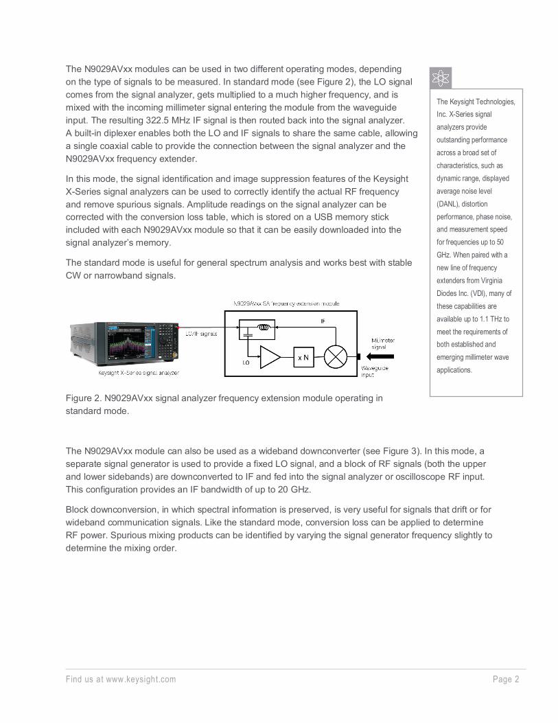
The N9029AVxx modules can be used in two different operating modes, depending on the type of signals to be measured. In standard mode (see Figure 2), the LO signal comes from the signal analyzer, gets multiplied to a much higher frequency, and is mixed with the incoming millimeter signal entering the module from the waveguide input. The resulting 322.5 MHz IF signal is then routed back into the signal analyzer. A built-in diplexer enables both the LO and IF signals to share the same cable, allowing a single coaxial cable to provide the connection between the signal analyzer and the N9029AVxx frequency extender.
In this mode, the signal identification and image suppression features of the Keysight X-Series signal analyzers can be used to correctly identify the actual RF frequency and remove spurious signals. Amplitude readings on the signal analyzer can be corrected with the conversion loss table, which is stored on a USB memory stick included with each N9029AVxx module so that it can be easily downloaded into the signal analyzer’s memory.
The standard mode is useful for general spectrum analysis and works best with stable CW or narrowband signals.
Figure 2. N9029AVxx signal analyzer frequency extension module operating in standard mode.
The N9029AVxx module can also be used as a wideband downconverter (see Figure 3). In this mode, a separate signal generator is used to provide a fixed LO signal, and a block of RF signals (both the upper and lower sidebands) are downconverted to IF and fed into the signal analyzer or oscilloscope RF input. This configuration provides an IF bandwidth of up to 20 GHz.
Block downconversion, in which spectral information is preserved, is very useful for signals that drift or for wideband communication signals. Like the standard mode, conversion loss can be applied to determine RF power. Spurious mixing products can be identified by varying the signal generator frequency slightly to determine the mixing order.
The Keysight Technologies, Inc. X-Series signal analyzers provide outstanding performance across a broad set of characteristics, such as dynamic range, displayed average noise level (DANL), distortion performance, phase noise, and measurement speed for frequencies up to 50 GHz. When paired with a new line of frequency extenders from Virginia Diodes Inc. (VDI), many of these capabilities are available up to 1.1 THz to meet the requirements of both established and emerging millimeter wave applications.
Find us at www.keysight.com Page 3
Figure 3. N9029AVxx signal analyzer frequency extension module operating in downconverter mode.
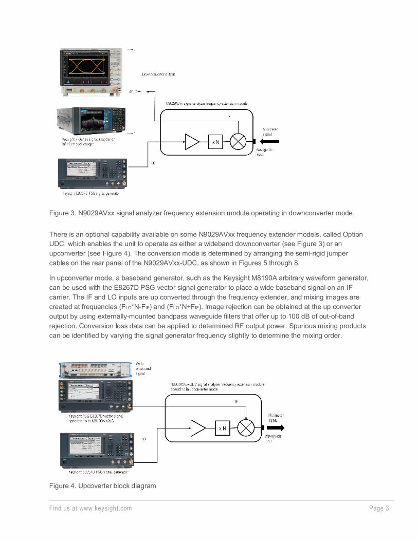
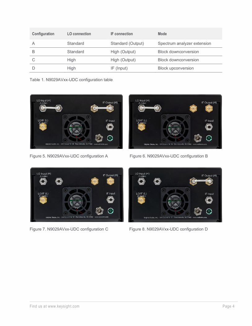
There is an optional capability available on some N9029AVxx frequency extender models, called Option UDC, which enables the unit to operate as either a wideband downconverter (see Figure 3) or an upconverter (see Figure 4). The conversion mode is determined by arranging the semi-rigid jumper cables on the rear panel of the N9029AVxx-UDC, as shown in Figures 5 through 8.
In upconverter mode, a baseband generator, such as the Keysight M8190A arbitrary waveform generator, can be used with the E8267D PSG vector signal generator to place a wide baseband signal on an IF carrier. The IF and LO inputs are up converted through the frequency extender, and mixing images are created at frequencies (FLO*N-FIF) and (FLO*N+FIF). Image rejection can be obtained at the up converter output by using externally-mounted bandpass waveguide filters that offer up to 100 dB of out-of-band rejection. Conversion loss data can be applied to determined RF output power. Spurious mixing products can be identified by varying the signal generator frequency slightly to determine the mixing order.
Figure 4. Upcoverter block diagram
Find us at www.keysight.com Page 4
Configuration LO connection IF connection Mode
A Standard Standard (Output) Spectrum analyzer extension
B Standard High (Output) Block downconversion
C High High (Output) Block downconversion
D High IF (Input) Block upconversion
Table 1. N9029AVxx-UDC configuration table
Figure 5. N9029AVxx-UDC configuration A
Figure 7. N9029AVxx-UDC configuration C
Figure 6. N9029AVxx-UDC configuration B
Figure 8. N9029AVxx-UDC configuration D
Find us at www.keysight.com Page 5
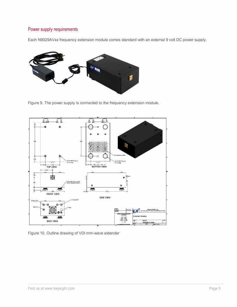
Power supply requirements
Each N9029AVxx frequency extension module comes standard with an external 9 volt DC power supply.
Figure 9. The power supply is connected to the frequency extension module.
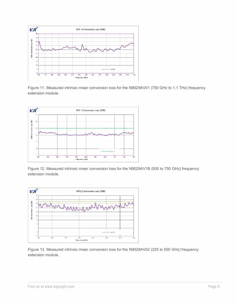
Figure 10. Outline drawing of VDI mm-wave extender
Find us at www.keysight.com Page 6
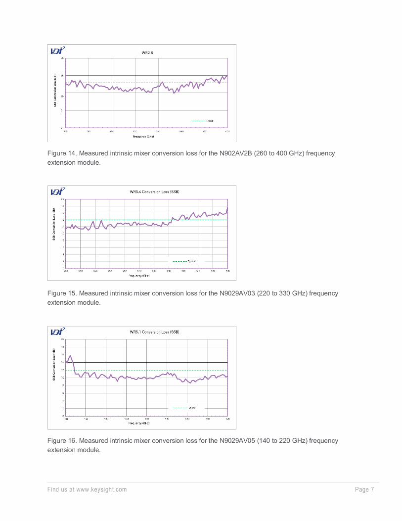
Figure 11. Measured intrinsic mixer conversion loss for the N9029AV01 (750 GHz to 1.1 THz) frequency extension module.
Figure 12. Measured intrinsic mixer conversion loss for the N9029AV1B (500 to 750 GHz) frequency extension module.
Figure 13. Measured intrinsic mixer conversion loss for the N9029AV02 (325 to 500 GHz) frequency extension module.
Find us at www.keysight.com Page 7
Figure 14. Measured intrinsic mixer conversion loss for the N902AV2B (260 to 400 GHz) frequency extension module.
Figure 15. Measured intrinsic mixer conversion loss for the N9029AV03 (220 to 330 GHz) frequency extension module.
Figure 16. Measured intrinsic mixer conversion loss for the N9029AV05 (140 to 220 GHz) frequency extension module.
Find us at www.keysight.com Page 8
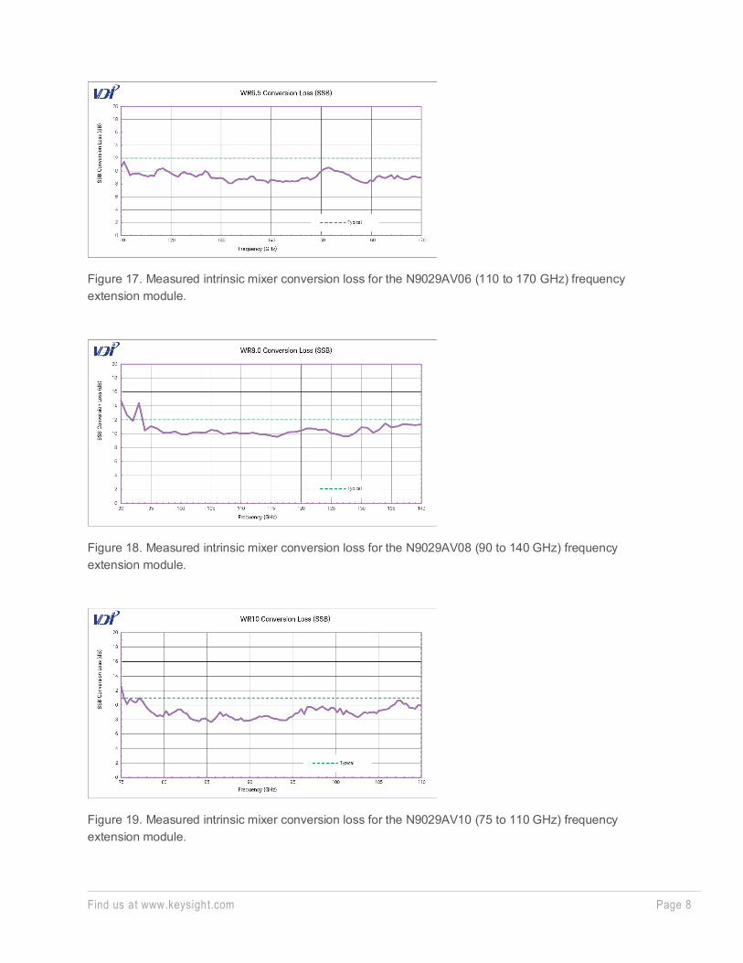
Figure 17. Measured intrinsic mixer conversion loss for the N9029AV06 (110 to 170 GHz) frequency extension module.
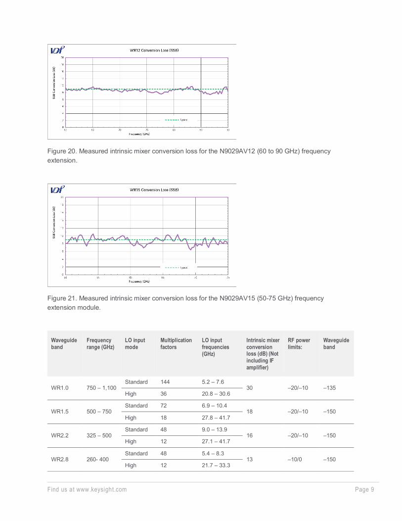
Figure 18. Measured intrinsic mixer conversion loss for the N9029AV08 (90 to 140 GHz) frequency extension module.
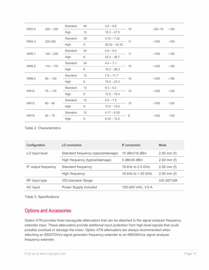
Figure 19. Measured intrinsic mixer conversion loss for the N9029AV10 (75 to 110 GHz) frequency extension module.
Find us at www.keysight.com Page 9
Figure 20. Measured intrinsic mixer conversion loss for the N9029AV12 (60 to 90 GHz) frequency extension.
Figure 21. Measured intrinsic mixer conversion loss for the N9029AV15 (50-75 GHz) frequency extension module.
Waveguide band
Frequency range (GHz)
LO input mode
Multiplication factors
LO input frequencies (GHz)
Intrinsic mixer conversion loss (dB) (Not including IF amplifier)
RF power limits:
Waveguide band
WR1.0 750 – 1,100 Standard 144 5.2 – 7.6
30 –20/–10 –135 High 36 20.8 – 30.6
WR1.5 500 – 750 Standard 72 6.9 – 10.4
18 –20/–10 –150 High 18 27.8 – 41.7
WR2.2 325 – 500 Standard 48 9.0 – 13.9
16 –20/–10 –150 High 12 27.1 – 41.7
WR2.8 260- 400 Standard 48 5.4 – 8.3
13 –10/0 –150 High 12 21.7 – 33.3
Find us at www.keysight.com Page 10
WR3.4 220 – 330 Standard 48 4.6 – 6.9
14 –20/–10 –150 High 12 18.3 – 27.5
WR4.3 220-330 Standard 36 4.72 – 7.22
11 –10/0 –150 High 6 28.33 – 43.33
WR5.1 140 – 220 Standard 24 5.8 – 9.2
11 –10/0 –150 High 6 23.3 – 36.7
WR6.5 110 – 170 Standard 24 4.6 – 7.1
10 –10/0 –150 High 6 18.3 – 28.3
WR8.0 90 – 140 Standard 12 7.5 – 11.7
10 –10/0 –150 High 6 15.0 – 23.3
WR10 75 – 110 Standard 12 6.3 – 9.2
10 –10/0 –150 High 6 12.5 – 18.3
WR12 60 – 90 Standard 12 5.0 – 7.5
10 –10/0 –150 High 6 10.0 – 15.0
WR15 50 – 75 Standard 12 4.17 – 6.25
9 –10/0 –150 High 6 8.33 – 12.5
Table 2. Characteristics
Configuration LO connection IF connection Mode
LO input level Standard frequency (typical/damage) 10 dBm/16 dBm 2.92 mm (f)
High frequency (typical/damage) 0 dBm/6 dBm 2.92 mm (f)
IF output frequency Standard frequency 16 kHz to 2.5 GHz 2.92 mm (f)
High frequency 16 kHz to < 20 GHz 2.92 mm (f)
RF input type VDI precision flange UG-387/UM
AC input Power Supply Included 100-240 VAC, 3.5 A
Table 3. Specifications
Options and Accessories
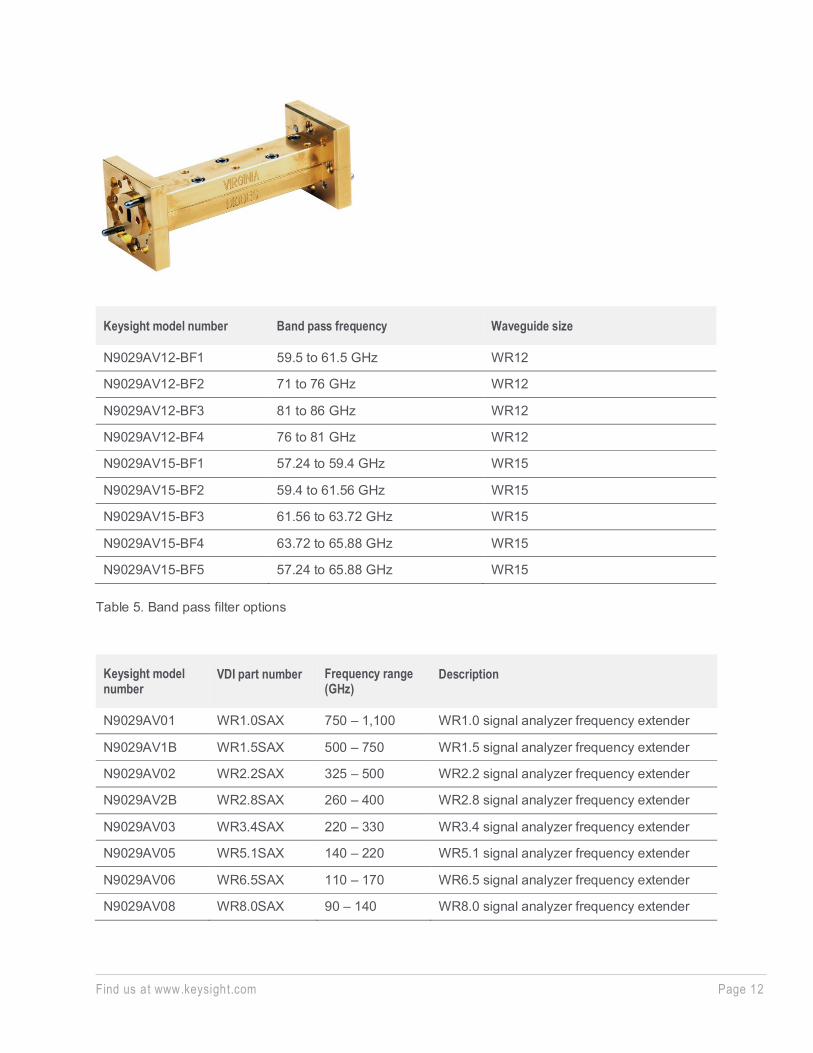
Option ATN provides fixed waveguide attenuators that can be attached to the signal analyzer frequency extender input. These attenuators provide additional input protection from high-level signals that could possibly overload or damage the mixer. Option ATN attenuators are always recommended when attaching an E8257DVxx signal generator frequency extender to an N9029AVxx signal analyzer frequency extender.
Find us at www.keysight.com Page 11
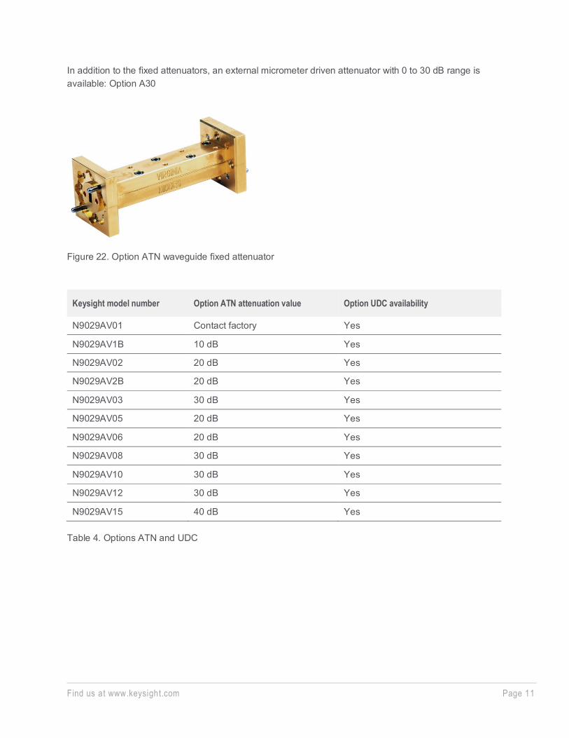
In addition to the fixed attenuators, an external micrometer driven attenuator with 0 to 30 dB range is available: Option A30
Figure 22. Option ATN waveguide fixed attenuator
Keysight model number Option ATN attenuation value Option UDC availability
N9029AV01 Contact factory Yes
N9029AV1B 10 dB Yes
N9029AV02 20 dB Yes
N9029AV2B 20 dB Yes
N9029AV03 30 dB Yes
N9029AV05 20 dB Yes
N9029AV06 20 dB Yes
N9029AV08 30 dB Yes
N9029AV10 30 dB Yes
N9029AV12 30 dB Yes
N9029AV15 40 dB Yes
Table 4. Options ATN and UDC
Find us at www.keysight.com Page 12
Keysight model number Band pass frequency Waveguide size
N9029AV12-BF1 59.5 to 61.5 GHz WR12
N9029AV12-BF2 71 to 76 GHz WR12
N9029AV12-BF3 81 to 86 GHz WR12
N9029AV12-BF4 76 to 81 GHz WR12
N9029AV15-BF1 57.24 to 59.4 GHz WR15
N9029AV15-BF2 59.4 to 61.56 GHz WR15
N9029AV15-BF3 61.56 to 63.72 GHz WR15
N9029AV15-BF4 63.72 to 65.88 GHz WR15
N9029AV15-BF5 57.24 to 65.88 GHz WR15
Table 5. Band pass filter options
Keysight model number
VDI part number Frequency range (GHz)
Description
N9029AV01 WR1.0SAX 750 – 1,100 WR1.0 signal analyzer frequency extender
N9029AV1B WR1.5SAX 500 – 750 WR1.5 signal analyzer frequency extender
N9029AV02 WR2.2SAX 325 – 500 WR2.2 signal analyzer frequency extender
N9029AV2B WR2.8SAX 260 – 400 WR2.8 signal analyzer frequency extender
N9029AV03 WR3.4SAX 220 – 330 WR3.4 signal analyzer frequency extender
N9029AV05 WR5.1SAX 140 – 220 WR5.1 signal analyzer frequency extender
N9029AV06 WR6.5SAX 110 – 170 WR6.5 signal analyzer frequency extender
N9029AV08 WR8.0SAX 90 – 140 WR8.0 signal analyzer frequency extender
Find us at www.keysight.com Page 13
N9029AV10 WR10SAX 75 – 110 WR10 signal analyzer frequency extender
N9029AV12 WR12SAX 60 – 90 WR12 signal analyzer frequency extender
N9029AV15 WR15SAX 50 – 75 WR15 signal analyzer frequency extender
Table 6. Ordering information
Option AMP provides waveguide amplification to the signal analyzer frequency extender input to overcome conversion loss and transmission loss. Option BF1 provides waveguide band pass filtering to the signal analyzer frequency extender input to filter one sideband and preserve signal modulation.
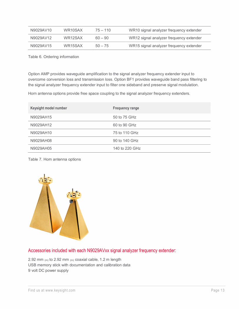
Horn antenna options provide free space coupling to the signal analyzer frequency extenders.
Keysight model number Frequency range
N9029AH15 50 to 75 GHz
N9029AH12 60 to 90 GHz
N9029AH10 75 to 110 GHz
N9029AH08 90 to 140 GHz
N9029AH05 140 to 220 GHz
Table 7. Horn antenna options
Accessories included with each N9029AVxx signal analyzer frequency extender: 2.92 mm (m) to 2.92 mm (m) coaxial cable, 1.2 m length USB memory stick with documentation and calibration data 9 volt DC power supply

Find us at www.keysight.com Page 14
Learn more at: www.keysight.com For more information on Keysight Technologies’ products, applications or services, please contact your local Keysight office. The complete list is available at: www.keysight.com/find/contactus
This information is subject to change without notice. © Keysight Technologies, 2016-2020, Published in USA, April 3, 2020, 5991-3161EN
Related Web Resources
For more information visit:
www.keysight.com/find/SA_mmwave www.keysight.com/find/PXA www.keysight.com/find/EXA www.keysight.com/find/SG_mmwave www.keysight.com/find/MXA
For more information on VDI’s signal analyzer frequency extenders, visit: www.vadiodes.com
Virginia Diodes Inc. contact info: 979 2nd Street, SE Suite 309 Charlottesville, VA 22902
Phone: (434) 297-3257 Fax: (434) 297-3258 Email: [email protected]