
Milli-Volt Micro-Electro-Mechanical Relay Technology for ...
57
Milli-Volt Micro-Electro-Mechanical Relay Technology for Energy-Efficient Computing Benjamin Osoba Electrical Engineering and Computer Sciences University of California, Berkeley Technical Report No. UCB/EECS-2021-27 http://www2.eecs.berkeley.edu/Pubs/TechRpts/2021/EECS-2021-27.html May 1, 2021
Transcript of Milli-Volt Micro-Electro-Mechanical Relay Technology for ...

Milli-Volt Micro-Electro-Mechanical Relay Technology
for Energy-Efficient Computing
Benjamin Osoba
Electrical Engineering and Computer SciencesUniversity of California, Berkeley
Technical Report No. UCB/EECS-2021-27
http://www2.eecs.berkeley.edu/Pubs/TechRpts/2021/EECS-2021-27.html
May 1, 2021

Copyright © 2021, by the author(s).All rights reserved.
Permission to make digital or hard copies of all or part of this work forpersonal or classroom use is granted without fee provided that copies arenot made or distributed for profit or commercial advantage and that copiesbear this notice and the full citation on the first page. To copy otherwise, torepublish, to post on servers or to redistribute to lists, requires prior specificpermission.

Milli-Volt Micro-Electro-Mechanical Relay Technology for Energy-Efficient Computing
By
Benjamin O. Osoba
A dissertation submitted in partial satisfaction of the
requirements for the degree of
Doctor of Philosophy
in
Engineering – Electrical Engineering and Computer Sciences
in the
Graduate Division
of the
University of California, Berkeley
Committee in charge:
Professor Tsu-Jae King Liu, Chair
Professor Kristofer Pister
Professor Junqiao Wu
Summer 2020

Milli-Volt Micro-Electro-Mechanical Relay Technology for Energy-Efficient Computing
Copyright ©2020
By
Benjamin O. Osoba
1
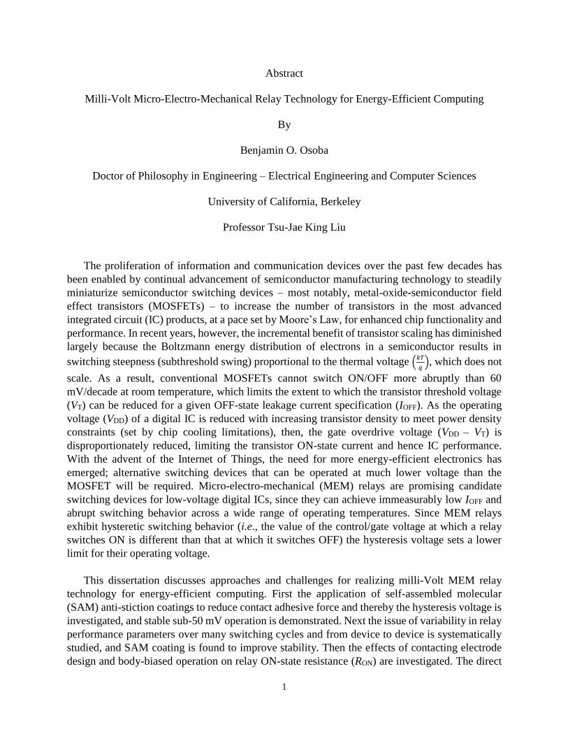
Abstract
Milli-Volt Micro-Electro-Mechanical Relay Technology for Energy-Efficient Computing
By
Benjamin O. Osoba
Doctor of Philosophy in Engineering – Electrical Engineering and Computer Sciences
University of California, Berkeley
Professor Tsu-Jae King Liu
The proliferation of information and communication devices over the past few decades has
been enabled by continual advancement of semiconductor manufacturing technology to steadily
miniaturize semiconductor switching devices – most notably, metal-oxide-semiconductor field
effect transistors (MOSFETs) – to increase the number of transistors in the most advanced
integrated circuit (IC) products, at a pace set by Moore’s Law, for enhanced chip functionality and
performance. In recent years, however, the incremental benefit of transistor scaling has diminished
largely because the Boltzmann energy distribution of electrons in a semiconductor results in
switching steepness (subthreshold swing) proportional to the thermal voltage (𝑘𝑇
𝑞), which does not
scale. As a result, conventional MOSFETs cannot switch ON/OFF more abruptly than 60
mV/decade at room temperature, which limits the extent to which the transistor threshold voltage
(VT) can be reduced for a given OFF-state leakage current specification (IOFF). As the operating
voltage (VDD) of a digital IC is reduced with increasing transistor density to meet power density
constraints (set by chip cooling limitations), then, the gate overdrive voltage (VDD – VT) is
disproportionately reduced, limiting the transistor ON-state current and hence IC performance.
With the advent of the Internet of Things, the need for more energy-efficient electronics has
emerged; alternative switching devices that can be operated at much lower voltage than the
MOSFET will be required. Micro-electro-mechanical (MEM) relays are promising candidate
switching devices for low-voltage digital ICs, since they can achieve immeasurably low IOFF and
abrupt switching behavior across a wide range of operating temperatures. Since MEM relays
exhibit hysteretic switching behavior (i.e., the value of the control/gate voltage at which a relay
switches ON is different than that at which it switches OFF) the hysteresis voltage sets a lower
limit for their operating voltage.
This dissertation discusses approaches and challenges for realizing milli-Volt MEM relay
technology for energy-efficient computing. First the application of self-assembled molecular
(SAM) anti-stiction coatings to reduce contact adhesive force and thereby the hysteresis voltage is
investigated, and stable sub-50 mV operation is demonstrated. Next the issue of variability in relay
performance parameters over many switching cycles and from device to device is systematically
studied, and SAM coating is found to improve stability. Then the effects of contacting electrode
design and body-biased operation on relay ON-state resistance (RON) are investigated. The direct

2
source/drain contact design provides for lowest and least variable RON. Ultra-low-voltage relay
operation facilitated by body-biasing results in lower contact velocity, which mitigates the need
for a wear-resistant contacting electrode material while necessitating a contacting electrode
material that is not susceptible to oxidation.

i
For my family,
past, present and future

ii
TABLE OF CONTENTS
Chapter 1: Introduction …………………………………………………………………….. 1
1.1 Brief History of Integrated Circuit (IC) Computing Devices ……………………. 1
1.2 CMOS Technology and Digital Logic …………………………………………… 1
1.3 CMOS Energy Efficiency Limit ………………………………………………… 4
1.4 MEM Relay Structure and Operation …………………………………………… 6
1.5 Relay Fabrication Process ……………………………………………………….. 8
1.6 Dissertation Objectives ………………………………………………………… 10
1.7 References ……………………………………………………………………… 10
Chapter 2: Sub-50 milli-volt NEM Relay Operation Enabled by Self-Assembled
Molecular Coating ……………………………………………………………. 13
2.1 Introduction ……………………………………………………………………. 13
2.2 Body-Bias Effect for Versatile Pass Gate Logic ………………………………. 14
2.3 Self-Assembled Monolayer (SAM) Molecular Coating ……………………….. 15
2.4 Effects of Molecular Coating on Relay Switching Characteristics ……………. 17
2.5 Discussion ……………………………………………………………………… 20
2.6 Summary ……………………………………………………………………….. 21
2.7 References ……………………………………………………………………… 21
Chapter 3: Variability Study for Low-Voltage Micro-Electro-Mechanical Relay
Operation ……………………………………………………………………… 23
3.1 Introduction ……………………………………………………………………. 23
3.2 Relay Switching Voltage Variability …………………………………………... 24
3.2.1. Body-biased switching voltage stability ……………………………….. 24
3.2.2. Process-induced variations ……………………………………………... 26
3.3 Effects of Anti-Stiction Coating ……………………………………………….. 27
3.4 Discussion ……………………………………………………………………… 29
3.5 Summary ……………………………………………………………………….. 29
3.6 References ……………………………………………………………………… 29
Chapter 4: Study of MEM Relay Contact Design and Body-Bias Effects on ON-state
Resistance Stability ……………………………………………………………. 31
4.1 Introduction ……………………………………………………………………. 31
4.2 Relay Design and Operation …………………………………………………… 31
4.3 Relay Fabrication Process ……………………………………………………... 33
4.4 Comparison of Relay Contact Design …………………………………………. 33

iii
4.5 Effects of Supply Voltage Scaling and Body-Bias …………………………….. 35
4.6 Discussion ……………………………………………………………………… 36
4.7 Summary ……………………………………………………………………….. 37
4.8 References ……………………………………………………………………… 37
Chapter 5: Conclusions and Future Work ……………………………………………….. 39
5.1 Summary of Research Contributions …………………………………………... 39
5.2 Possible Directions of Future Work …………………………………………… 40
5.3 References ……………………………………………………………………… 40
Appendix ………………………………………………………………………………………. 42

iv
LIST OF FIGURES
Chapter 1: Introduction
Fig. 1.1 Schematic illustrations of the structure, circuit symbol and ON state operation
conditions of (a) NMOS and (b) PMOS field effect transistors
Fig. 1.2 CMOS inverter (a) circuit diagram (b) voltage transfer curve
Fig. 1.3 CMOS logic and memory circuits (a) 2-input NAND gate (b) 2-input NOR gate and
(c) Static Random Access Memory (SRAM) cell and (d) Dynamic Random Access
Memory (DRAM) cell array
Fig. 1.4 Conceptual illustrations of (a) MOSFET transfer characteristic and (b) normalized
energy per digital CMOS operation
Fig. 1.5 (a) Plan-view scanning electron micrograph (SEM) image of a fabricated 6-terminal
MEM relay and (b) Schematic cross-section A-A’ in the OFF-state and ON-state
Fig. 1.6 (a) Illustration of electrostatic actuation and spring restoring forces in the MEM relay
and (b) measured I-V characteristics
Fig. 1.7 CoventorWare MEMS+ simulated relay fabrication process
Chapter 2: Sub-50 milli-volt NEM Relay Operation Enabled by Self-Assembled Molecular
Coating
Fig. 2.1 (a) Measured relay I-V characteristics showing the effect of body-biasing, which is
utilized to achieve low-voltage operation for (b) pull-down (N-relay) operation and (c)
pull-up (P-relay) operation
Fig. 2.2 (a) Relay inverter circuit and (b) measured voltage waveforms for inverter circuit in
which a non-coated relay is configured as a pull-down device
Fig. 2.3 (a) Molecular structure of PFDTES and (b) qualitatitve illustration of PFDTES coating
Fig. 2.4 (a) photograph and (b) qualitative illustration of the vapor phase molecular coating
process
Fig. 2.5 Contact-angle measurements (a) pre- and (b) post- SAM-coating
Fig. 2.6 (a) Characteristic peaks from X-ray Photoelectron Spectroscopy (XPS) measurements
and (b) the fluorine peak
Fig. 2.7 (a) SEM image of SiO2 AFM tip, (b) illustration of Atomic Force Microscope (AFM)
adhesion force measurement and (c) empirical measurements indicating that surface
adhesion is decreased with PFDTES coating
Fig. 2.8 Summary of measured data, pre- and post-PFDTES coating
Fig. 2.9 Measured RON data for L = 15 µm relays operated at VB = -9 V and VIN = VDD = 3 V
Fig. 2.10 (a) Measured L = 8 µm relay I-V characteristics (pre- and post- PFDTES coating) and
(b) measured voltage waveforms for inverter circuit in which a relay coated with
PFDTES is configured as a pull-down device

v
Fig. 2.11 An alkane molecule with Young’s modulus in the GPa regime and poly(ethylene
glycol) with Young’s modulus in the MPa regime, shown as examples of chemical
synthesis
Fig. 2.12 Measured voltage waveforms demonstrating sub-50 mV relay-based inverter circuit
operation
Fig. 2.13 Molecular structure of PFOTES
Fig. 2.14 (a) AFM-based measurements of coated contact adhesive force and (b) measured relay
I-V characteristics, comparing the effects of PFOTES and PFDTES anti-stiction
coatings
Chapter 3: Variability Study for Low-Voltage Micro-Electro-Mechanical Relay Operation
Fig. 3.1 Stable low voltage operation over 100 DC sweeps enabled by body-biasing
Fig. 3.2 Evolution of (a) relay switching voltages and (b) hysteresis voltage for a body-biased
relay operated with various values of drain-to-source voltage VDS
Fig. 3.3 Measured variability in (a) VPI and (b) VH for multiple relays operated at varying VB
Fig. 3.4 Measured impact of process-induced variations in Poly-Si0.4Ge0.6 thickness on (a) VPI
(b) actuation gap g and (c) VH
Fig. 3.5 Measured switching voltages for multiple relays operated at VDS = 1V and VB = -14.5V
Fig. 3.6 Molecular structure of (a) PFDTES vs. (b) PFOTES (c) measured I-V characteristics
for body-biased relays, showing the effects of anti-stiction coatings
Fig. 3.7 (a) Measured I-V characteristics and (b) evolution of measured VH for PFOTES-coated
MEM relay operated over 100 gate voltage sweeps at VDS = 1 V and body-biased
conditions
Fig. 3.8 Measured (a) variability in VPI, VH and (b) switching voltages for multiple PFOTES
relays operated at VDS = 1 V and VB = -16 V
Chapter 4: Study of MEM Relay Contact Design and Body-Bias Effects on ON-state
Resistance Stability
Fig. 4.1 SEM micrograph images (top) and schematic cross-sections (bottom) of relays with
different contacting electrode designs in the OFF state and in the ON state: (a) dual
bridge source/drain contact, (b) dual direct source/drain contact, and (c) single direct
source/drain contact
Fig. 4.2 Measured I-V characteristics for body-biased relays of various contact designs
Fig. 4.3 Average measured values of (a) VH and (b) RON for 10 relays of each contact design
with VB = 0V
Fig. 4.4 Relay-based inverter circuit utilized for RON characterization
Fig. 4.5 Measured RON as a function of the number of ON/OFF switching cycles, for MEM
relays of varying contact design

vi
Fig. 4.6 Measured RON as a function of the number of ON/OFF switching cycles, for a single-
direct contact relay measured with varying (a) VDD and (b) VB
Fig. 4.7 Numerically simulated relay contact velocity under varying (a) VB and (b) VOD
operating conditions

vii
ACKNOWLEDGMENTS
“It was all a dream…” These words certainly ring true as it pertains to this academic milestone
and I have to begin by giving all glory to God for allowing me to see it through. There have been
many highs and lows throughout my graduate school experience and I would be remiss if I did not
express my appreciation to those who have proven pivotal in my matriculation. I feel that this
dissertation and my graduation experience in general are testaments to the Yoruba proverb
A kò lè tìtorí pé ọ̀nà jìn kí a wá padà sẹ́hìn, meaning “Because the destination is far, is no reason
to stop a journey.” Despite the often challenging times, my support system was always there to
provide the advice, comfort, and guidance that has helped me to transverse this journey and
ultimately succeed.
I would like to give gratitude to my advisor, Professor Tsu-Jae King Liu, for her continuous
guidance and support throughout my graduate studies at Berkeley. Through your example of
technical innovation, research acumen and vision, I feel that I have grown leaps and bounds as an
academic and scholar. I appreciate your willingness to not only mentor me as a researcher, but also
as a leader and member of the greater campus community. You believed in me even when I did
not believe in myself and it is your steadfast support which truly made the difference in my
development as an engineer. I hope one day to not only continue your legacy of technical
achievement, but also impact younger generations of engineers just as you have done for me.
I would also like to thank Prof. Kristofer Pister for meaningful conversations about interesting
applications for mechanical devices, improvements on quantitative research methodology, and
analog circuits. I am grateful for your willingness to serve as the chair of my qualifying exam
committee, and for also serving on my thesis committee. Furthermore, I would like to thank Profs.
Ana Arias and Junqiao Wu for also serving on these committees and providing frequent advice
throughout the various stages of graduate school. I would like to thank Prof. Jeffrey Bokor for
taking the extra time to work with me on quantum mechanics and other advanced engineering
concepts outside of class. I would also like to thank Profs. Chenming Hu, Sayeef Salahuddin,
Vivek Subramanian, Clark Nguyen, Boubacar Kanté, Ali Javey, and Seth Sanders for their
instruction and career advice in the field of electrical engineering.
I would also like to thank all of the EECS department and College of Engineering faculty/staff
who were involved in helping me administratively and technically. This includes Charlene
Hughes, Dahlia Case, Audrey Sillers, Susanne Kauer, Tiffany Reardon, Meltem Erol, Lea Marlor,
Charlotte Jones, Dr. Josephine Yuen, Dr. Kedrick Perry, Dr. Sharnnia Artis (now at UC Irvine),
Prof. Oscar Dubon, Prof. Kara Nelson, and many others, all of whom helped provide me with a
strong foundation at Berkeley. I would especially like to thank Shirley Salanio for her continuous
advice and encouragement, especially in the times of adversity. I would like to thank Dr. Sheila
Humphrey as well for her kindness and willingness to share insight and literature about Berkeley
history.
I would like to thank my friends, classmates and colleagues, who all provided both levity
amidst the often difficult work of research and motivation in form of community. To my entering
class cohort – including Drs. Carlos Biaou, Juan Pablo Llinas, Akshay Pattabi, Jodi Loo, Mahsa

viii
Sadeghi, Oladapo Afolabi, Howard Mao, and Jane Yu – I love you and thank you for helping me
to get through the tough times. Thank you to Dr. William Tarpeh, Dr. Pierce Gordon, Dr. Kene
Akametalu, Dr. Frances Roberts-Gregory and other Black student leaders for helping me to learn
different ways to serve my community. I appreciate the Black Graduate Engineering and Science
Students (BGESS) for allowing me to serve as a student leader and learn in greater detail about
the systemic obstacles facing African and African-American students; I hope to use this knowledge
to break down barriers for Black engineers who will be following behind me. Thank you to my
friends Robert Baker, Juan Lascano, Sam Owens, Jaime Hinckson, Chad Evans, Candace
Gilchrist, Khalia Braswell, Dr. Racheida Lewis, Joshua Sherfield, Dr. Sara Awartani, Azzedin
Jackson, Christiane Stachl, Opeyemi Ogedengbe and Aaron McFall for a consistent listening ear
and for providing a support system outside of academics.
I must also express my deep gratitude to the King Liu research group and my collaborators for
this thesis project: Urmita Sikder, Zhixin Alice Ye, Tsegereda Esatu, Lars Tatum, Xiaoer Hu, Jatin
Patil, Laura Brandt, Maurice Roots, Edgar Acosta, Liam Dougherty, Jane Edgington, Kathy Le,
Dr. Nuo Xu, Dr. I-Ru Chen, Dr. Yenhao Chen, Dr. Bivas Saha, Dr. Sergio Almeida, Dr. Kimihiko
Kato, Dr. Sangwan Kim, Dr. Fei Ding, Dr. Chuang Qian, Dr. Xi (Robin) Zhang, Dr. Thomas
Rembrandt, Dr. Daniel Connelly, Dr. Rebecca Mih, Dr. Alexis Peschot, and Dr. Farnaz Niroui.
Without all of your expertise and frequent discussions, I would not have learned as much nor
improved to this degree as an academic. I’ve all of our group picnics and outings as well, you all
are the best!
Thank you to Dr. Bill Flounders for access to the Marvell Nanofabrication Laboratory, where
much of this work was completed. I would also like to thank nanolab staff – including Richelieu
Hemphill, Brian McNeil, Danny Pestal, Ryan Rivers, and Dr. Jeffrey Clarkson – for helping me
learn the various fabrication and lab maintenance processes.
Thank you to Bishop J.W. Macklin, Elder Michael Head, Elder Marcus Williams, and my
entire church family at Glad Tidings International Church of God in Christ for all of your support
and spiritual guidance.
Thank you to the National Science Foundation, Ford Foundation, and National GEM
Consortium for offering fellowship support and funding for my graduate education.
I would also like to thank my various mentors for providing unwavering guidance throughout
my life. This includes Dr. Frances Williams, Dr. Demetris Geddis, Dr. Jeremy Waisome, Dr.
Aliecia McClain, and Jelece Morris, each of whom has been directly responsible for my interest
in engineering to begin with.
Finally, I would like to give all of my love and gratitude to my family, especially my loving
wife, Charise Osoba. I could not have overcome the many obstacles of completing graduate school
without the steadfast support and foundation you provided for me. To my parents Babajide and
Teresa Osoba, I am indebted to the sacrifices and efforts you made for me when I was young. To
my sisters Omoniyi Obioha, Folakemi Okeowo and my Godbrother Quinn Andrews, thank you
for your love and support. Without each of you, I would not have been able to stay grounded and
motivated to complete this journey. I dedicate this document to you.

1
CHAPTER 1:
Introduction
1.1 BRIEF HISTORY OF INTEGRATED CIRCUIT (IC) COMPUTING DEVICES
Since the late 1950s, the electronics industry has rapidly advanced and proliferated throughout
the world, bringing about the digital information age that has transformed various aspects of life
in modern society. Examples include the Apollo Guidance Computer that facilitated the successful
Apollo space program in the 1960s [1], and computer control of sound synthesizers via the Musical
Instrument Digital Interface (MIDI) invented in 1982 [2] that revolutionized music performance,
production and recording. The development of the integrated circuit (IC) [3] and steady
advancement in planar semiconductor processing technology [4] to enable ever higher levels of
component integration on an IC “chip” following Moore’s Law [5] has provided for continual
reductions in cost per function and increases in computing performance (operations per second).
Today, state-of-the-art ICs comprise billions of semiconductor devices known as transistors. The
Metal Oxide Semiconductor Field Effect Transistor (MOSFET) is the predominant type of
transistor used for computational ICs, and act as switches that either allow current to flow (in the
ON state) or prevent current from flowing (in the OFF state) to implement digital logic functions
[6][7].
1.2 CMOS TECHNOLOGY AND DIGITAL LOGIC
Schematic illustrations of n-channel (NMOS) and p-channel (PMOS) field-effect transistor
structures are shown in Fig. 1.1. The ON/OFF state of a MOSFET is controlled via voltage applied
to the Gate electrode (VG) relative to the voltage applied to the heavily doped (electrically
conductive) Source region (VS). The Gate voltage is capacitively coupled to the electric potential
of the semiconductor Channel region under the Gate electrode, and thereby controls the height of

2
the potential barrier between the heavily doped (electrically conductive) Source region and the
Channel region. When a driving voltage (VDS) is applied between the Source and Drain regions,
the rate of thermionic emission of mobile charge carriers from the Source region into the Channel
region (which is doped of opposite conductivity type as the Source and Drain regions) increases
exponentially as the height of this source injection barrier is reduced linearly with increasing
VGS ≡ VG – VS. When |VGS| is increased beyond a certain threshold voltage (VT), transistor current
flow is no longer limited by thermionic emission; an inversion layer of mobile charge (“channel”)
forms at the surface of the semiconductor under the Gate electrode, allowing electric current to
easily flow between the Source region and the heavily doped Drain region if VDS ≠ 0, limited by
carrier drift velocity. For NMOS devices, VG must be higher than VS by at least VT (i.e., VGS > VT)
in order for an inversion layer of electrons to form at the surface of the semiconductor so that
electrons can flow from the n-type Source region through the channel to the n-type Drain region.
For PMOS devices, VG must be lower than VS by at least VT (i.e., VGS < -VT) in order for an
inversion layer of positively charged holes to form at the surface of the semiconductor so that holes
can flow from the p-type Source region through the channel to the p-type Drain region. NMOS
and PMOS FET symbols used for circuit diagrams, and their switching requirements, are also
shown in Fig. 1.1.
N-channel MOSFET
NMOS circuit symbol
ON if 𝑉𝐺𝑆 > 𝑉𝑇 (a)
P-channel MOSFET
PMOS circuit symbol
ON if 𝑉𝐺𝑆 < −𝑉𝑇 (b)
Fig. 1.1 Schematic illustrations of the structure, circuit symbol and ON state operation
conditions of (a) NMOS and (b) PMOS field effect transistors. Critical dimensions are
indicated: gate length (LG), spacer length (LSP), source/drain extension junction depth (XJ), and
bulk dopant concentration (NA, ND).
NMOS and PMOS field-effect transistors are fabricated and electrically connected together to
form ICs [4] that perform a variety of digital logic operations [6][7]. The simplest logic circuit is
the inverter, illustrated in Fig. 1.2, comprising a pair of NMOS and PMOS transistors. As shown
in Fig. 1.2(a), the transistor Gate electrodes are connected together to form the input node, while
the transistor Drain electrodes are connected together to form the output note; the NMOS Source
is biased at the lowest voltage (ground, or 0 V) while the PMOS Source is biased at the highest

3
voltage (the power supply voltage, VDD). The transistors operate in a complementary manner, i.e.,
when one turns ON the other turns OFF, and vice versa: The NMOS transistor is ON when the
input voltage is high (e.g., VDD), connecting the output node to ground; hence it is referred to as a
“pull-down” device. The PMOS transistor is ON when the input voltage is low, connecting the
output node to VDD; hence it is referred to as a “pull-up” device.
When the input node is charged so that the input voltage (VIN) changes from 0 V to VDD, the
NMOS transistor turns ON while the PMOS transistor turns OFF, i.e., the output node is
discharged through the NMOS transistor so that the output voltage (VOUT) is “pulled down” to 0
V, following the voltage transfer characteristic (Fig. 1.2(b)). The time required for this operation
depends on the NMOS transistor ON-state “drive” current and the capacitance of the output node;
the larger the drive current and/or the smaller the output node capacitance, the faster the output
node discharges to ground. Similarly, the time required for VOUT to transition from 0 V to VDD after
VIN transitions from VDD to 0 V depends on the PMOS transistor drive current and the capacitance
of the output node.
Note that when the inverter is static (i.e., not transitioning from one state to the other), one
transistor is ON while the other is OFF. Moreover, the transistor that is OFF sustains a large voltage
difference between the Source and Drain regions (VDS), resulting in OFF-state leakage current
(IOFF) – which the other transistor readily allows to flow since it is ON. Therefore, power is
continuously dissipated (VDD×IOFF) when a CMOS logic circuit is static.
CMOS inverter circuit
(a)
Inverter voltage transfer curve
(VTC) and logic symbol
(b)
Fig. 1.2 CMOS inverter (a) circuit diagram (b) voltage transfer curve [7].
More complex logic functions are implemented with complementary pairs of NMOS and PMOS
transistors that serve as pull-down and pull-up devices, respectively; hence the term “CMOS” logic
technology. Examples include NAND (Fig. 1.3(a)) and NOR (Fig. 1.3(b)) digital logic gates. A
static memory (SRAM) cell is implemented with two cross-coupled inverters and an additional
two NMOS transistors used to pull-down their respective storage nodes during a write or read
operation. A more compact but dynamic (i.e., requiring periodic refreshing) memory (DRAM) cell
comprises a single NMOS transistor and a capacitor to store charge (Fig. 1.3(c-d)) [8].

4
CMOS NAND gate
NAND Truth Table
A B VOUT
0 0 1
0 1 1
1 0 1
1 1 0
(a)
CMOS NOR gate
NOR Truth Table
A B VOUT
0 0 1
0 1 0
1 0 0
1 1 0
(b)
SRAM cell
(c)
DRAM cell
(d)
Fig. 1.3 CMOS logic and memory circuits (a) 2-input NAND gate (b) 2-input NOR gate and (c) Static Random Access Memory
(SRAM) cell and (d) Dynamic Random Access Memory (DRAM) cell array [8]. Logic ‘1’ corresponds to high voltage; logic
‘0’ corresponds to low voltage.
1.3 CMOS ENERGY EFFICIENCY LIMIT
Traditionally, transistor miniaturization (i.e., dimensional scaling) was accompanied by
commensurate reduction in operating voltage (VDD) to maintain a constant peak electric field
(desirable for ensuring long-term reliability of transistor operation), a trend known as “Dennard
Scaling” [9]. This scaling methodology provided for improved circuit operating speed at a constant
chip power density. Since the 2000s, however, voltage scaling slowed down even as transistor
scaling continued, because the VT of a MOSFET cannot be scaled too close to 0 V because IOFF
increases exponentially (Fig. 1.4(a)) and hence the static power dissipation of a CMOS circuit
increases exponentially with decreasing VT. The operating speed of a CMOS circuit is dependent
on transistor on-state drive current (ION), which in turn is dependent on the gate overdrive voltage
(VDD VT); a reduction in VDD would result in smaller ION and hence slower circuit operation, if
VT cannot also be reduced.
The emergence of the “Internet of Things” in recent years has led to the need for more energy-
efficient computing devices. Any CMOS-based digital logic circuit has a fundamental energy
efficiency limit, however, due to non-zero transistor leakage current. This can be understood by
considering the dynamic component (due to capacitive charging/discharging, proportional to the
square of VDD) and static component (due to transistor OFF-state leakage, proportional to VDD and

5
also to tdelay) of energy consumed per operation by a generic combinational logic circuit comprising
a cascade of logic gates [10]:
𝐸𝑡𝑜𝑡𝑎𝑙 = 𝛼𝐿𝑑𝑓𝐶𝑉𝐷𝐷2 + 𝐿𝑑𝑓𝐼𝑂𝐹𝐹𝑉𝐷𝐷𝑡𝑑𝑒𝑙𝑎𝑦 (1.1)
𝑡𝑑𝑒𝑙𝑎𝑦 = 𝐿𝑑𝑓𝐶𝑉𝐷𝐷 (2𝐼𝑂𝑁) (1.2)⁄
where α is the activity factor, Ld is logic depth, f is fanout, C is capacitance per logic stage, and
tdelay is the time required to complete the logic operation.
As the time required to complete the digital operation increases (or, equivalently, circuit operating
speed decreases), the energy that is wasted due to IOFF increases, eventually to the point of making
further reduction in VDD counterproductive in terms of energy efficiency. This point corresponds
to VDD = VT.
(a)
(b)
Fig. 1.4 Conceptual illustrations of (a) MOSFET transfer characteristic (for different values of VDD with VT adjusted to achieve the same ON-state drive current, ION) and (b) normalized energy per digital CMOS operation, showing how the total energy consumed per operation has a minimum due to transistor leakage current (IOFF) [10].
In order to reduce the minimum energy per operation (i.e., to improve energy efficiency), VT
must be reduced without increasing IOFF. This means that the steepness of the transistor transfer
characteristic (Fig. 1.4(a)) in the region where the gate voltage is smaller than the threshold
voltage, i.e., the “subthreshold swing” (SS) must be steeper. SS for a MOSFET is fundamentally
limited to be no smaller than (𝑘𝑇
𝑞) (ln 10), which is approximately 60 mV/decade at room
temperature, due to the Boltzmann energy distribution of electrons in the Source region of the
transistor [7]. For this reason, alternative solid-state switching devices have been investigated [11].
Although alternative transistor designs such as the tunnel field-effect transistor (TFET) [12] and
negative capacitance FET (NC-FET) [13] can achieve steeper switching characteristics than the
MOSFET, they also can be more sensitive to process-induced variations and device operating
conditions, which practically limits their benefit. For example, switching abruptness can be
degraded by trap-assisted tunneling due to interfacial defects in a TFET [14] and by polarization
screening in a NC-FET [15].

6
Micro-electro-mechanical (MEM) switches (relays) can achieve immeasurably low IOFF and
abrupt switching behavior across a wide range of temperatures [16]; in principle, they can be
operated with much lower voltage than can any type of transistor. (Although they switch more
slowly than do transistors, circuit design optimization to minimize the number of mechanical
switching delays per function can compensate for this [17].) Thus, MEM switches are of keen
interest for digital IC applications for which energy efficiency is paramount. In this dissertation,
challenges for achieving reliable millivolt relay operation are investigated. While piezoelectric
MEM relays have also been studied for millivolt switching [18], this dissertation focuses on
electrostatically actuated relay designs because they can be fabricated with a simpler process flow.
Nevertheless, insights for achieving reliable millivolt operation of electrostatic relays should also
apply for piezoelectric relays.
1.4 MEM RELAY STRUCTURE AND OPERATION
Fig. 1.5(a) shows a plan-view scanning electron microscope (SEM) image of a 6-terminal
(6-T) relay developed for digital logic IC applications [19]. This device comprises a movable gate
electrode suspended by four folded-flexure beams (nominal length L = 12 m) over a fixed body
electrode. As shown in the schematic cross-section of the relay in Fig. 1.5(b), with nominal as-
fabricated actuation air gap (g0) of 220 nm and nominal as-fabricated contact air gap (gd) of 60 nm
in the OFF state, narrow strips of W (50 nm thick) are attached to the underside of the gate
insulating layer (50 nm thick). These “channels” serve to bridge their respective S/D electrodes
when the relay is in the ON state, allowing current (IDS) to flow in response to a source-drain
voltage difference, as also illustrated in Fig. 1.5(b).
To switch ON the relay, a voltage (VGB) is applied between the gate and the body, inducing
electrostatic force (Felec) that actuates the gate downward (Fig. 1.6(a)). Simultaneously, as the
structure’s displacement from its equilibrium position increases, the spring restoring force Fspring
of the deformed suspension beams increases linearly (in the opposite direction). Balancing these
opposing forces, one can see that the displacement g of the structure rapidly increases with
increasing VGB:
𝑔 = 𝑔0 −𝜀0𝐴𝑉𝐺𝐵
2
2𝑘𝑒𝑓𝑓𝑔2 (1.3)
where g0 is the initial (as-fabricated) actuation gap, keff is the effective spring constant of the
suspension beams, 0 is the vacuum permittivity, and A is the effective actuation area. If g is
reduced by 1
3𝑔0, the inherent positive feedback within this system causes the structure to become
unstable and collapse downward – a phenomenon known as pull-in [20].

7
(a)
a/b – – – – – – – – – – – – – – – – – – – – – – a’/b’
OFF-state
ON-state
(b) Fig. 1.5 (a) Plan-view scanning electron micrograph (SEM) image of a fabricated 6-terminal MEM relay [26]
and (b) Schematic cross-section A-A’ in the OFF-state and ON-state. In the ON-state, surface adhesive force
exists, resulting in hysteretic switching behavior.
When the magnitude of VGB is increased to be equal to or greater than that of the pull-in voltage
(VPI), the channels come into physical contact with their respective S/D electrodes, allowing an
abrupt increase in current conduction. Subsequently when |VGB| is reduced below the magnitude
of the release voltage (VRL), the spring restoring force (Fspring) of the suspension beams is sufficient
to overcome Felec and the contact adhesive force (FA) so that the channels are separated from their
respective S/D electrodes and the relay turns off. As explained in [21], high device manufacturing
yield can be achieved by designing relays to have relatively stiff structures and large air gaps as
fabricated; subsequently they can be made to operate with a small gate voltage (VG) swing by
applying a body bias voltage (VB) (Fig. 1.6(b)).
(a)
(b)
Fig. 1.6 (a) Illustration of electrostatic actuation and spring restoring forces in the MEM relay and (b) measured
I-V characteristics for a relay operated with VDS = 1 V and various body bias voltages VB. The current is limited
to be 10 A to avoid contact welding due to Joule heating.

8
It should be noted that relays can be designed to be normally off (i.e., actuated into the ON
state via VGB) or to be normally on (i.e., actuated into the OFF state via VGB). Furthermore, a
normally-off relay can be designed to avoid the pull-in phenomenon by making the as-fabricated
contact gap smaller than 1
3𝑔0, i.e., 𝑔0 > 3𝑔𝑑. While previous energy-delay analyses [21-23]
indicate that it is energetically favorable for relays to operate in non-pull-in mode, practical
challenges (e.g., variations in the fabrication process, non-zero strain gradient in the structural
material) make this difficult to achieve in practice [24-26]. As such, the relays utilized in this study
were designed for pull-in mode operation. Based on the aforementioned electrostatic and
mechanical force-balancing with respect to VGB, the formulae for VPI and VRL of a pull-in mode
relay are as follows:
𝑉𝑃𝐼 = √8𝑘𝑒𝑓𝑓𝑔0
3
27𝜀0𝐴 (1.4)
𝑉𝑅𝐿 = √2(𝑘𝑒𝑓𝑓𝑔𝑑−𝐹𝐴)(𝑔0−𝑔𝑑)
2
𝜀0𝐴 (1.5)
where FA is the contact surface adhesive force. Adhesive force is due primarily to van der Waals
forces in the contact dimple regions in the ON state [27].
1.5 RELAY FABRICATION PROCESS
Details of the MEM relay fabrication process flow are provided in [19]. For the relays studied
in this dissertation, the two sets of conducting source and drain (S/D) electrodes are coplanar with
the body electrode, formed from the same layer of 50 nm-thick tungsten (W) deposited by sputter
deposition (Fig. 1.7(b)) over the insulating substrate (Fig. 1.7(a)). LPCVD SiO2 (Fig. 1.7(c)) was
used as the sacrificial material so that the relays could be released using vapor-phase hydrofluoric
acid (HF). Al2O3 deposited by atomic layer deposition (ALD) is used as the body (Fig. 1.7(e)) and
substrate (Fig. 1.7(a)) insulator material because of its resistance to vapor-HF treatment. The
structural (gate and suspension beams) material is 1.75 m-thick in-situ boron doped
polycrystalline silicon-germanium (poly-Si0.4Ge0.6) deposited by low-pressure chemical vapor
deposition (LPCVD) (Fig. 1.7(f)). The aforementioned relay dimensions are summarized in
Table 1.1.
TABLE 1.1
Nominal design parameter values for relays used in this study
Design Parameter Value
Poly-Si0.4Ge0.6 Thickness, t 1.75 µm
Beam Width, W 2 µm
Beam Length, L {8, 12} µm
Actuation Area, A 1236 µm2
Actuation Gap, g0 220 nm
Contact Dimple Gap, gd 60 nm
Contact Area, ACONT 1 µm2

9
(a)
(d)
(b)
(e)
(c)
(f)
Fig. 1.7 CoventorWare MEMS+ simulated relay fabrication, showing deposition and patterning of (a) Al2O3 substrate dielectric,
(b) W body/source/drain fixed electrodes, (c) sacrificial low temperature oxide and contact dimples, (d) W channel, (e) gate
dielectric and structural anchor regions, and (f) Poly-Si0.4Ge0.6 structure (after HF vapor release). [19]
The relays in this work were released using a uEtch Primaxx anhydrous HF vapor process, in
order to avoid catastrophic pull-in and stiction due to capillary forces. The release recipe, noted in
Table 1.2, consists of 15-17 cycles of stabilization, etching, and pumping; the respective durations
(per cycle) of each of these steps is also shown in Table 1.2. Further information regarding this
tool and etch process are available in the Marvell Nanofabrication Laboratory equipment manual
[28].
TABLE 1.2.
Primaxx HF Vapor release recipe utilized in this study N2 (sccm) EtOH (sccm) HF (sccm) Time (min)
Stabilize 1250 350 0 2
Etch 1250 350 310 5
Pump 0 0 0 0.5

10
In this work, MEM relays were electrically characterized using a Lakeshore TTPX cryogenic
vacuum probe station at ~1.5 µTorr. Prior to collecting data, a native-oxide breakdown process
was performed by applying 100 voltage pulses (~5 V, f = 10 kHz) between the source and drain
electrodes with the relay in the ON-state, to achieve a reasonably low (less than 1 kΩ) initial ON-
state resistance [10].
1.6 DISSERTATION OBJECTIVES
This dissertation discusses approaches and challenges for realizing reliable millivolt MEM
relay operation for energy-efficient computing. The hysteresis voltage caused by surface adhesive
force at the contact dimples during operation is the primary bottleneck for VDD scaling for relay-
based ICs, therefore possible methods to resolving this issue are investigated.
In chapter 2, post-fabrication treatment of the contacting electrode surfaces with a self-
assembled molecular (SAM) anti-stiction coating is demonstrated to effectively reduce surface
adhesive force FA. This process is shown to enable stable sub-50 mV operation.
In chapter 3, the issue of variability in relay performance parameters over many switching
cycles and from device to device is systematically studied with respect to operating conditions and
contact treatment. SAM coating is found to improve switching stability for a single device and to
reduce variation in hysteresis voltage from device to device.
In chapter 4, the effects of contacting electrode design and body-biased operation on relay ON-
state resistance (RON) are investigated. A direct source/drain contact design provides for lowest
and least variable RON. Ultra-low-voltage relay operation facilitated by body-biasing results in
lower contact velocity, which mitigates the need for a wear-resistant contacting electrode material
while necessitating a contacting electrode material that is not susceptible to oxidation.
Chapter 5 discusses key findings of this work and suggests possible directions of future
research.
1.7 REFERENCES
[1] “Computers on board the Apollo spacecraft,” Computers in Space Flight: the NASA
Experience, NASA, https://history.nasa.gov/computers/Ch2-5.html
[2] “MIDI is born 1980-1983,” MIDI History, MIDI Association.
https://www.midi.org/articles/midi-history-chapter-6-midi-is-born-1980-1983
[3] From concept to cosmos: How Jack Kilby’s integrated circuit transformed the electronics
industry, Texas Instruments, 2019. https://news.ti.com/blog/2019/09/17/from-concept-to-
cosmos-how-jack-kilbys-integrated-circuit-transformed-electronics-industry
[4] R.C. Jaeger, Introduction to Microelectronic Fabrication, 2nd Ed. Prentice-Hall, Inc. 2002.
[5] G.E. Moore, “Cramming more components onto integrated circuits,” Electronics, vol. 38, no.
8, 1965

11
[6] R.F. Pierret, Semiconductor Device Fundamentals, Addison-Wesley Publishing Co., 1996.
[7] Y. Taur and T. H. Ning, Fundamentals of Modern VLSI Devices, 2nd Ed., Cambridge University
Press, 2009
[8] B.J. LaMeres, Introduction to Logic Circuit and Logic Design with Verilog. 1st Ed. Springer
Nature, 2017.
[9] R.H. Dennard, F.H. Gaensslen, H.-N. Yu, V.L. Rideout, E. Bassous, A.R. Leblanc, “Design of
ion-implanted MOSFETs with very small physical dimensions,” IEEE Journal of Solid-State
Circuits, Vol. 9, 1974
[10] B. Calhoun, A. Wang, and A. Chandrakasan, “Modeling and sizing for minimum energy
operation in subthreshold circuits,” IEEE Journal of Solid-State Circuits, Vol. 40, No. 9, pp.
1778-1786, 2005.
[11] A.M. Ionescu, “Energy efficient computing and sensing in the Zettabyte era: from silicon to
the cloud,”
[12] A.M. Ionescu and H. Riel, “Tunnel field-effect transistors as energy-efficient electronic
switches,” Nature, Vol. 479, pp. 329-337, 2011.
[13] S. Salahuddin and S. Datta, “Use of negative capacitance to provide voltage amplification for
low power nanoscale devices,” ACS Nano Letters, Vol. 8, pp. 405-410, 2008
[14] R. N. Sajjad, W. Chern, J. L. Hoyt, and D. A. Antoniadis, “Trap assisted tunneling and its
effect on subthreshold swing of tunnel field effect transistors,” in Cond-Mat.Mes-Hall, Mar.
2016.
[15] K. Ng, S. J. Hillenius, and A. Gruverman, “Transient nature of negative capacitance in
ferroelectric field-effect transistors,” Solid State Communications, Vol. 265, pp. 12-14, 2017.
[16] H. Kam, V. Pott, R. Nathanael, J. Jeon, E. Alon, and T. J. King Liu, “Design and reliability
of a micro-relay technology for zero-standby-power digital logic applications,” IEEE IEDM
Tech. Dig., pp. 809-811, 2009.
[17] F. Chen, H. Kam, D. Markovic, T. J. King Liu, V. Stojanovic, E. Alon, “Integrated circuit
design with NEM relays,” Proc. IEEE/ACM ICCAD, pp. 750-757, 2008.
[18] U. Zahloul and G. Piazza, “10-25 nm piezoelectric nano-actuators and NEMS switches for
millivolt computational logic,” Sub-1-volt piezoelectric nanoelectromechanical relays with
millivolt switching capability,” IEEE 26th Int’l. Conf. MEMS, 2013
[19] R. Nathanael et al., "Multi-input/multi-output relay design for more compact and versatile
implementation of digital logic with zero leakage," Proceedings of Technical Program of 2012
VLSI Technology, System and Application.
[20] H. Nathanson et al., “The resonant gate transistor,” IEEE Trans. on Elec. Devices, vol. ed-14
No. 3, 1967.
[21] C. Qian, A. Peschot, D. J. Connelly, and T. J. King Liu, “Energy-delay performance
optimization of NEM logic relay,” IEEE IEDM Tech. Dig., pp. 475-478, 2015.
[22] C. Qian et al., “Effect of body biasing on the energy-delay performance of logic relays,” IEEE
Electro Device Letters, 2015.
[23] C. Qian, “Electro-mechanical devices for ultra-low-power electronics,” Ph.D. dissertation,
University of California, Berkeley, 2017.
[24] C. Low, “Characterization of polycrystalline silicon-germanium film deposition for modularly
integrated MEMS applications,” Proc. Jour. of MEMS, Vol. 16, No. 1, Feb. 2007.
[25] C. Low, “Novel processes for modular integration of silicon-germanium MEMS with CMOS
electronics,” Ph.D. dissertation, University of California, Berkeley, 2007.
[26] B. Osoba et al., “Variability study for low-voltage microelectromechanical relay operation,”

12
IEEE Trans. on Elec. Devices, Feb. 2018
[27] J. Yaung, L. Hutin, J. Jeon, and T.-J. King Liu, “Adhesive force characterization for MEM
logic relays with sub-micron contacting regions,” IEEE JMEMS, Vol. 23, No. 1, 2014
[28] “uEtch HF Vapor Release System,” Equipment Manual, Marvell Nanofabrication Laboratory,
UC Berkeley. https://nanolab.berkeley.edu/public/manuals/equipment_manual.shtml

13
CHAPTER 2:
Sub-50 milli-volt NEM Relay Operation Enabled by Self-Assembled
Molecular Coating
2.1 INTRODUCTION
Due to the aforementioned limitations of conventional semiconductor transistors – particularly
the Boltzmann distribution of electrons that is exponentially dependent on the thermal voltage 𝑘𝑇
𝑞,
which limits the subthreshold swing (SS) of transistors to be no steeper than approximately 60
mV/dec at room temperature – nanometer-scale electro-mechanical (NEM) switches (relays) are
of keen interest for ultra-low-power digital logic integrated circuit (IC) applications [1]. This is
because a mechanical switch can achieve the ideal property of zero OFF-state leakage current, in
turn providing for zero static power consumption [1][2]. To minimize active power consumption,
the operating voltage (VDD) of a digital IC should be minimized.
VDD scaling for a NEM relay is limited by the switching hysteresis voltage that is caused by
contact stiction [3]. When a relay is in the ON-state, surface adhesive force exists in the contact
dimple regions, so that the electrostatic force required to maintain the relay in the ON-state is
smaller than the electrostatic force required to actuate the relay into the ON-state. Thus, the turn-
off voltage is smaller than the turn-on voltage, resulting in the aforementioned hysteresis voltage.
For this reason, it is of paramount importance to investigate how to mitigate – and ultimately
eliminate – surface adhesion in the relay contact regions. In this chapter, reduction in contact
adhesive force via the application of an anti-stiction molecular coating is investigated.

14
2.2 BODY BIAS EFFECT FOR VERSATILE PASS GATE LOGIC
The 6T relays [4] in this work were tested at room temperature using a vacuum probe station
(1.5 Torr) to minimize oxidation of the W electrode surfaces which is undesirable because WOx
is electrically insulating, resulting in high ON-state resistance [5]. Measured current-vs.-voltage
(I-V) characteristics for forward and reverse sweeps of the gate voltage (VG) are shown in
Fig. 2.1(a). By applying a negative body voltage (VB), the positive value of VG that is required to
turn ON the relay (VDD) can be decreased to VPI – |VB|. The maximum value of |VB| that can be
applied (while ensuring that the relay is OFF at VG = 0 V) is VRL, so that the minimum VDD is the
hysteresis voltage VH ≡ VPI − VRL. Sub-200 mV operation with negative body biasing is
demonstrated in Fig. 2.1(b). In a digital logic circuit, the switching devices are used not only to
pass low voltage (0 V) as in a “pull-down” device but also to pass high voltage (VDD) as in a “pull-
up” device. For a relay to operate as a pull-up device, it must switch ON with decreasing VG. In
this case, to achieve ultra-low-voltage operation, a positive body bias should be used as
demonstrated in Fig. 2.1(c).
(a)
(b)
(c)
Fig. 2.1 (a) Measured relay I-V characteristics showing the effect of body-biasing, which is utilized to achieve low-voltage
operation for (b) pull-down (N-relay) operation and (c) pull-up (P-relay) operation. IDS is artificially limited to 100 nA in order
to prevent Joule heating and subsequent W welding at the relay contacts.
Fig. 2.2(a) illustrates an inverter circuit in which the body-biased relay is used as a pull-down
device, and Fig. 2.2(b) shows measured input and output voltage waveforms for this circuit.
(a)
(b)
Fig. 2.2. (a) Relay inverter circuit and (b) measured voltage waveforms for inverter circuit in which a non-coated relay is
configured as a pull-down device. RL = 123 kΩ, VDD = VIN,max = 3 V, VB = -11.75 V, and f = 1 kHz. (vOUT does not reach VDD
due to oscilloscope internal resistance Rosc = 1 M.)

15
This inverter circuit is used to extract the value of relay ON-state resistance (RON) via the voltage
divider formula:
𝑉𝑂𝑈𝑇 ≅ (𝑅𝑂𝑁
𝑅𝑂𝑁+𝑅𝐿)𝑉𝐷𝐷 (2.1)
𝑅𝑂𝑁 ≅ (𝑉𝑂𝑈𝑇
𝑉𝐷𝐷−𝑉𝑂𝑈𝑇)𝑅𝐿 (2.2)
Because the oscilloscope internal resistance (Rosc = 1 M) is relatively large in comparison to RON,
it can be considered negligible in the voltage division estimation. However, the load resistance RL
is significant compared to Rosc so that it cannot be ignored:
𝑉𝑂𝑈𝑇 =
{
(
𝑅𝑜𝑠𝑐𝑅𝐿 + 𝑅𝑜𝑠𝑐
)𝑉𝐷𝐷 , 𝑓𝑜𝑟 𝑉𝐼𝑁 = 0 𝑉 (2.3)
[𝑅𝑂𝑁𝑅𝑜𝑠𝑐
𝑅𝑂𝑁𝑅𝑜𝑠𝑐 + (𝑅𝑂𝑁 + 𝑅𝑜𝑠𝑐)𝑅𝐿] 𝑉𝐷𝐷 , 𝑓𝑜𝑟 𝑉𝐼𝑁 = 𝑉𝐷𝐷 (2.4)
The value of RL affects the current flowing through the relay contacts. As such, this parameter can
be tuned in order to obtain optimal circuit performance. A low value of RL facilitates in situ
electrical breakdown of native oxide formed on the surfaces of the contacting asperities during
ON-state conduction, and reduces the effect of Rosc when the relay is in the OFF state. However if
RL is too low, excessive Joule heating could resulting in micro-welding, causing the relay to be
stuck in the ON state. RL = 123 k was chosen for the tests conducted in this chapter.
2.3 SELF-ASSEMBLED MONOLAYER (SAM) MOLECULAR COATING
Hydrophobic 1H,1H,2H,2H-Perfluorodecyltriethoxysilane (PFDTES, Fig. 2.3(a)) was
selected as the relay coating material in this work. The silane functional group of this molecule
allows its assembly onto oxidized surfaces [14] and hence facilitates self-assembly onto native
WOx on the contact surfaces (Fig. 2.3(b)) while the fluorinated backbone lowers the surface energy
and reduces adhesive force [17-19] as shown quantitatively in Fig. 2.7(c).
(a)
(b) Fig. 2.3 (a) Molecular structure of PFDTES and (b) qualitatitve illustration of PFDTES coating, which adheres
well to W surfaces due to its silane end-group.

16
Utilizing Atomic Force Microscopy (AFM) and the Derjaguin, Muller and Toporov (DMT)
model for an adhesive contact [14, 15, 19]
𝐹𝐴𝐷𝐻 = 𝑊𝐴𝐷𝐻 ∙ 2𝜋𝑅𝑡𝑖𝑝 (2.5)
where 𝑊𝐴𝐷𝐻 is the measured work of adhesion with respect to the normal plane and 𝑅𝑡𝑖𝑝 is the
radius of the AFM tip, the effect of PFDTES coating was first characterized.
In this work, PFDTES was deposited using a vapor-phase process as shown in Fig. 2.4. A few
drops of the liquid-phase molecules were placed in close proximity to the samples to be coated,
inside a vacuum desiccator where the pressure was reduced to vaporize the molecules. The samples
were left in this environment for ~24 hours to ensure full coverage.
Fig. 2.4 (a) photograph and (b) qualitative illustration of the vapor phase molecular coating process, during which
the molecules self-assemble onto the sample surfaces.
Contact angle measurements were conducted on samples before and after in order to confirm that
the silane functional group assembled effectively. Because fluorinated molecules are hydrophobic,
a drop of water on a coated surface results in a higher contact angle than a non-coated surface, as
shown in Fig. 2.5. As such, self-assembly of PFDTES on W electrode material was confirmed.
(a)
(b)
Fig. 2.5 Contact-angle measurements (a) 30 ̊ pre-coating and (b) 97 ̊ post-coating
indicate successful deposition of the fluorinated molecule.

17
In addition, X-ray Photoelectron Spectroscopy (XPS) measurements confirm successful coating
of W with PFDTES, as indicated in Fig. 2.6.
(a)
(b)
Fig. 2.6 (a) Characteristic peaks from XPS measurements and (b) the fluorine peak, indicating the successful self-
assembly of PFDTES onto the W surface.
To provide reference data, a silicon-dioxide AFM tip (Fig. 2.7(a)) was brought into and out of
contact with the surface of an oxidized silicon wafer, 10 times at each of 5 different locations on
the surface for a total of 50 measurements of adhesive force [14 - 16]. This test was then conducted
for a PFDTES-coated AFM tip to PFDTES-coated wafer (Fig. 2.7(b)). The results of these tests
as shown in Fig. 2.7(c) indicate that PFDTES effectively decreases surface adhesive force.
(a)
(c)
(b)
Fig. 2.7 (a) SEM image of SiO2 AFM tip, (b) illustration of Atomic Force Microscope (AFM) adhesion force
measurement and (c) empirical measurements indicating that surface adhesion is decreased with PFDTES coating.
2.4 EFFECTS OF MOLECULAR COATING ON RELAY SWITCHING CHARACTERISTICS
After initial testing, relays were coated with PFDTES using the vapor-phase growth process
and then retested. For 6 relays of identical design, IDS-VG characteristics were measured multiple
times (i.e. with multiple forward and reverse VG sweeps) to obtain the average value of VH. The
results shown in Fig. 2.8(a) indicate that the PFDTES coating significantly reduces VH, by 41%
on average both for zero body bias and non-zero body bias. It also reduces VH variation from one

18
device to another, from 8.3 mill-volt to 7.4 milli-volt (standard deviation) for body-biased relays.
From Fig. 2.8(b) it is evident that relays operated with body biasing generally have lower VH and
variability due to lower contact velocity; molecular coating is as effective for reducing VH in this
case.
(a)
(b)
Fig. 2.8 Summary of measured data, pre- and post-PFDTES coating, showing decrease in switching hysteresis voltage VH for
(a) zero body bias, (b) VB = - 9 V.
Fig. 2.9 shows that the PFDTES does not
substantially change the relay ON-state
resistance (RON). This is likely because any
PFDTES at the small number of contacting
asperities (cf. Fig. 2.3(b)) is electrically broken
down or ablated due to local Joule heating.
Fig. 2.10(a) shows measured IDS-VG
characteristics for a coated relay with body
biasing. Note that although VH (measured at a
current level of 10 nA) is reduced by the
PFDTES coating, the transitions between OFF
and ON states are less abrupt, i.e. the
subthreshold swing is increased to ~15 mV/dec.
Therefore, a larger gate voltage swing is needed
to fully switch the relay ON. However, if a
smaller ON/OFF current ratio (e.g. 104) is
sufficient, then the coated relay can be operated
Fig. 2.9 Measured RON data for L = 15 µm relays operated
at VB = -9 V and VIN = VDD = 3 V. These data show no
significant increase in relay ON-state resistance with
PFDTES coating. Notably, the VIN value was chosen to
account for process-induced variation in VPI for the given set
of relays.
with a smaller gate voltage swing. This is in contrast to an abruptly switching relay, which cannot
be operated with a gate voltage swing that is smaller than VH. By applying a body bias to bring the
molecular coatings on the S/D and channel electrodes into contact, a metal-molecule-metal
“squitch” [17][18] is effectively achieved. The molecular material can be engineered for more
abrupt switching behavior, through chemical synthesis techniques, to modify the functional end

19
group and/or the spacer backbone. For example, a lower Young’s modulus molecular layer can be
achieved by changing the spacer group.
(a)
(b)
Fig. 2.10 (a) Measured L = 8 m relay I-V characteristics showing that PFDTES coating can provide for smaller VH. (b)
Measured voltage waveforms for inverter circuit in which a relay coated with PFDTES is configured as a pull-down device.
RL = 123 kΩ, Rosc = 1 M, VDD = VIN = 200 mV, VBn = -12.34 V, and f = 1 kHz.
Fig. 2.11 shows an example of shorter alkane molecule with Young’s modulus in the GPa regime
compared to longer chain poly(ethylene glycol) which exhibits a Young’s modulus as low as a few
MPa [17-19].
Fig. 2.11 Through chemical synthesis, molecules can be designed with
particular head, terminal and spacer groups to exhibit desired surface
selectivity for device functionalization, surface adhesive properties, and
electromechanical performance. Here, an alkane molecule with Young’s
modulus in the GPa regime and poly(ethylene glycol) with Young’s modulus
in the MPa regime are shown as examples.
Fig. 2.12(b) shows measured voltage waveforms for an inverter circuit in which the body-biased
coated relay is used as a pull-down device (cf. Fig. 2.2(a)). As the input voltage (VIN) amplitude
decreases, the relay ON state current is reduced so that it cannot fully discharge the output node

20
and hence the minimum output voltage (VOUT,MIN) rises. Fig. 2.12 shows voltage waveforms for
relay-based inverter circuits, demonstrating sub-50 milli-volt operation (VIN = VDD).
(a)
(b)
Fig. 2.12 Measured voltage waveforms demonstrating sub-50 mV relay-based inverter circuit operation: (a) N-relay
configuration with VBn = -14.96 V, and (b) P-relay configuration with VBp = 14.1 V. RL = 123 kΩ, Rosc = 1 M,
VDD = VIN = 40 mV, and f = 1 kHz.
2.5 DISCUSSION
The experimental results show that PFDTES is effective for reducing surface adhesion and
hence VH, thereby enabling reliable sub-50 milli-volt relay operation for both pull-up and pull-
down operation (cf. Fig. 2.12). This comes at the tradeoff of reduced switching abruptness,
however, resulting in degraded ON/OFF ratio for the same (small) gate-voltage swing. Effectively,
RON for low-VDD operation is increased, resulting in significantly degraded output voltage swing.
This issue is exacerbated by the softer contacting force for body-biased operation [6-8]. For
VDD = VIN = 40 mV, the pull-down and pull-up relays have effective 𝑅𝑂𝑁𝑁−𝑟𝑒𝑙𝑎𝑦 ≈ 369 kΩ and
𝑅𝑂𝑁𝑃−𝑟𝑒𝑙𝑎𝑦 ≈ 205 kΩ, respectively.
Perfluorooctyltriethoxysilane (PFOTES)
Fig. 2.13 Molecular structure of PFOTES
Alternative fluorinated molecules, such as perfluorooctyltriethoxysilane (PFOTES, Fig. 2.13),
could be used as anti-stiction coating material [11]. The quantity n of difluoromethane (CF2) within

21
the larger fluorinated chain affects the overall length of the molecule. Measurements of PFOTES-
coated relays indicate that the shorter molecule (n = 5) results in lower surface adhesive force
(Fig. 2.14 (a)) and smaller VH (Fig. 2.14 (b)) in comparison with PFDTES.
(a)
(b)
Fig. 2.14 (a) AFM-based measurements of coated contact adhesive force and (b) measured relay I-V characteristics,
comparing the effects of PFOTES and PFDTES anti-stiction coatings.
2.6 SUMMARY
Reduction of the hysteresis voltage VH is key to minimizing the gate voltage swing of a relay
and thereby the active power consumption of relay-based digital ICs. Self-assembled monolayer
PFDTES coating is found to be effective for reducing VH (by more than 41%) without significantly
affecting ON-state resistance, enabling lower voltage operation. Further work is needed to
optimize the molecular coating material to achieve more abrupt switching behavior, to fully realize
the benefit of lower VH for lower the operating voltage and hence for improving MEM relay
operating energy efficiency.
2.7 REFERENCES
[1] F. Chen et al., "Integrated circuit design with NEM relays," 2008 IEEE/ACM Int’l Conf.
Computer-Aided Design, pp. 750-757, 2008.
[2] A. Peschot et al., “Nanoelectromechanical switches for low-power digital computing,”
Micromachines, vol. 6, no. 8, pp. 1046-1065, 2015.
[3] C. Pawashe et al., “Scaling limits of electrostatic nanorelays,” IEEE Trans. Elec. Dev., vol. 60,
pp. 2936-2942, 2013.
[4] R. Nathanael et al., "Multi-input/multi-output relay design for more compact and versatile
implementation of digital logic with zero leakage," Proceedings of Technical Program of 2012
VLSI Technology, System and Application.
[5] Y. Chen et al., "Reliability of MEM relays for zero leakage logic," Proc. SPIE 8614, Reliability,
Packaging, Testing, and Characterization of MOEMS/MEMS and Nanodevices XII, p. 861404,
2013.

22
[6] C. Qian et al., “Effect of body biasing on the energy-delay performance of logic relays,” IEEE
Electro Device Letters, 2015.
[7] C. Qian et al., “Energy-delay performance optimization of NEM logic relay,” 2015 IEEE
International Electron Devices Meeting, paper 18.1.
[8] C. Qian, “Electro-mechanical devices for ultra-low-power electronics,” Ph.D. dissertation,
University of California, Berkeley, 2017.
[9] C. Low, “Characterization of polycrystalline silicon-germanium film deposition for modularly
integrated MEMS applications,” Proc. Jour. of MEMS, Vol. 16, No. 1, Feb. 2007.
[10] C. Low, “Novel processes for modular integration of silicon-germanium MEMS with
CMOS electronics,” Ph.D. dissertation, University of California, Berkeley, 2007.
[11] B. Osoba et al., “Variability study for low-voltage microelectromechanical relay
operation,” IEEE Trans. on Elec. Devices, Feb. 2018
[12] J. Yaung, “NEM relay scaling for ultra-low power digital logic,” Ph.D. dissertation,
University of California, Berkeley, 2014.
[13] R. Maboudian et al., “Self-assembled monolayers as anti-stiction coatings for MEMS:
characteristics and recent developments,” Sensors and Actuators 82, pp. 219 – 223, 2000.
[14] G. Binning et al., “Atomic Force Microscopy,” Phy. Rev. Lett. 56, pp. 930 – 933, 1986.
[15] F. Leite et al., “Theoretical models for surface forces and adhesion and their measurement
using atomic force microscopy,” Int. J. Mol. Sci., 2012.
[16] K. Cooper et al., “Substrate morphology and particle adhesion in reacting systems,”
JCIS 228, pp. 213-219, 2000.
[17] F. Niroui et al., “Nanoelectromechanical tunneling switches based on self-assembled
molecular layers,” 2014 IEEE 27th International Conference on Micro Electro Mechanical
Systems, pp. 1103-1106.
[18] F. Niroui et al., “Tunneling nanoelectromechanical switches based on compressible
molecular thin-films,” ACS Nano, vol. 9, no. 8, pp. 7886-7894, 2015.
[19] F. W. DelRio et al., “Elastic and adhesive properties of alkanethiol self assembled
monolayers on gold,” Appl. Phys. Lett., vol. 94, p. 131909, 2009.

23
CHAPTER 3:
Variability Study for Low-Voltage Micro-Electro-Mechanical Relay
Operation
3.1 INTRODUCTION
In order to overcome the inherent switching energy efficiency limitation of conventional
transistors [1], there have been many efforts to develop alternative solid-state switch designs that
can achieve more ideal (i.e., abrupt) switching characteristics [2-6]. Micro/nano-electro-
mechanical (M/NEM) switches are a promising alternative to conventional transistors for
applications in which energy efficiency is paramount, primarily because the former can achieve
immeasurably low OFF-state leakage current (IOFF) and abrupt switching behavior across a wide
range of temperatures [7]. In principle, NEM relays can be operated with much lower voltage than
can any type of transistor. (Although they switch more slowly than do transistors, circuit design
optimization to minimize the number of mechanical switching delays per function can compensate
for this [8].) A body-biased MEM relay design was previously developed for digital IC
applications [9] and shown to provide for improved energy efficiency [10].
In Chapter 2, an anti-stiction self-assembled monolayer (SAM) coating was demonstrated to
reduce the relay switching hysteresis voltage (VH VPI VRL) so that the relay can be switched
ON/OFF with sub-50 milli-volt gate voltage (VG) swing; therefore, in principle, the operating
voltage (VDD) of a relay-based integrated circuit (IC) can be less than 50 mV. However, due to
variations in turn-on/pull-in voltage (VPI) and release voltage (VRL) values from device to device,
VDD must include voltage margin for these variations. In this chapter, variability in relay switching
voltages and the impact of SAM coating on variability are investigated.

24
3.2 RELAY SWITCHING VOLTAGE VARIABILITY
Switching voltage variations practically limit the extent to which VDD can be reduced, because
in practice a single negative value of VB should be used for all of the “pull-down” relays within a
circuit block, while another single positive value of VB should be used for all of the “pull-up”
relays within a circuit block. In order for a relay-based IC to operate properly, then, the magnitude
of the applied body bias voltage (|VB|) cannot be larger than the minimum value of release voltage
(VRL low), to guarantee that each relay turns OFF properly; also, VDD must be at least equal to the
maximum value of VPI (VPI high) minus VRLlow, to guarantee that each relay turns ON properly.
Therefore, VDD scaling is constrained by the maximum and minimum values of VPI and VRL,
respectively:
𝑉𝐷𝐷 ≥ 𝑉𝑃𝐼ℎ𝑖𝑔ℎ + 𝑉𝐵 (3.1)
|𝑉𝐵| ≤ 𝑉𝑅𝐿𝑙𝑜𝑤 (3.2)
3.2.1. Body-biased switching voltage stability
Process-induced variations in relay dimensions, as well as random variations in FA from device
to device and over the device operating lifetime, result in switching voltage variations. Fig. 3.1
shows measured switching voltages for 100 sequential DC measurements made on a single body-
biased relay.
Fig. 3.1 Stable low voltage operation is enabled by body-biasing, with less
than 100 mV variation in VPI and VRL over 100 gate voltage sweeps. The
ON-state current was artificially limited to 10 µA, to prevent excessive
Joule heating resulting in micro-welding. L = 8 µm.

25
The plotted data in Fig. 3.2 show that VPI is very stable after the first ~20 sweeps, while VH
increases slightly (by ~20 mV) over time, possibly due to initial contact wear-in, stabilizing after
~50 sweeps. Weak dependence on the drain-to-source voltage (VDS) is seen. The relays in this work
were tested at room temperature under vacuum (~1.5 μTorr).
(a)
(b)
Fig. 3.2 Evolution of (a) relay switching voltages and (b) hysteresis voltage for a body-biased relay operated with
various values of drain-to-source voltage VDS. L = 8 µm. The current compliance limit was set to 10 A.
Fig. 3.3 shows that body biasing is generally advantageous for improving switching voltage
stability (i.e., reducing variability in VPI and VH). This is likely due to the reduction in impact
velocity enabled by increased |VB| [10].
(a)
(b)
Fig. 3.3 Measured variability in (a) VPI and (b) VH for multiple relays operated at VDS = 1 V with VB = 0 V or
VB = -14.5 V. Body biasing generally decreases variability in VPI and VH. L = 8 µm. The current compliance
limit was set to 10 A.

26
3.2.2. Process-induced variations
The LPCVD processes used to deposit the sacrificial SiO2 and structural poly-Si0.4Ge0.6 layers
in this work resulted in significant systematic variations across a wafer (i.e., die to die) and random
variations from device to device, in the thicknesses of the actuation and contact gaps and the
movable structure, as determined using an Olympus LEXT OLS4000 3D confocal laser
microscope. Notably, the structural thickness of these relays was 1.6 µm, as opposed to the nominal
thickness listed in Table 1.1.
Fig. 3.4(a) shows how VPI varies with poly-Si0.4Ge0.6 thickness. Utilizing Eqn. 1.4 and noting
that 𝑘𝑒𝑓𝑓 ∝ 𝑡3, the theoretical change in VPI relative to its nominal value due to a change in
poly-Si0.4Ge0.6 thickness t and actuation gap g thickness is given by the following relationship:
𝑉𝑃𝐼 = (𝑔 ∗ 𝑡
𝑔0 ∗ 𝑡0)
32⁄
∗ 𝑉𝑃𝐼0 (3.3)
(a)
(b)
(c)
Fig. 3.4 Measured impact of process-induced variations in Poly-Si0.4Ge0.6 thickness on (a) pull in voltage VPI (b) actuation gap g
and (c) hysteresis voltage VH. L = 12 µm. The negative correlation between structural layer thickness and actuation gap size is
due to reduced out-of-plane deflection for a stiffer structure.
By comparing the measured VPI values against the theoretically predicted trend based on
Eqn. 3.3, indicated by the solid red line in Fig. 3.4(a), taking into account the negative correlation
between structural layer thickness and actuation gap size shown in Fig. 3.4(b), it can be seen that
random sources of variation are predominant. (Measured values 𝑔0 = 0.35 µm, 𝑡0 = 1.5 µm, and
𝑉𝑃𝐼0= 11.9 V were used to calibrate the theoretical curve.) The systematic variation is relatively
small and can be further reduced in a relatively straightforward manner with improved LPCVD
process control. Fig. 3.4(c) shows that there is significant random variation in VH, which depends
on local contact properties that vary from device to device.

27
Fig. 3.5 Measured switching voltages for multiple relays operated
at VDS = 1 V and VB = -14.5 V. The error bars correspond to
switching variation measured for each relay over 100 gate voltage
sweeps. L = 8 µm.
Fig. 3.5 shows the variation in switching voltages for relays located side-by-side on a single
die, with the same value of VB that was chosen to guarantee proper IC functionality. Although VH
can be less than 100 mV, random variability limits VDD to be no less than ~0.9 V for this die. More
uniform (device to device) switching voltages are necessary to overcome this issue, to fully realize
the benefit of relay technology for ultra-low-voltage integrated circuits.
3.4 EFFECTS OF ANTI-STICTION COATING
In the previous chapter it was demonstrated that a hydrophobic coating of
Perfluorodecyltriethoxysilane (PFDTES) is effective for reducing VH, but at a tradeoff of increased
sub-threshold swing, i.e. less abrupt switching behavior [11]. As seen in Fig. 3.6, a molecular
coating with a shorter perfluoro chain, Perfluorooctyltriethoxysilane (PFOTES), was used in this
work to mitigate the aforementioned tradeoff (cf. Sec. 2.5).
Perfluorodecyltriethoxysilane (PFDTES)
(a)
(c)
Perfluorooctyltriethoxysilane (PFOTES)
(b)
Fig. 3.6 Molecular structure of (a) PFDTES vs. (b) PFOTES, (c) measured I-V characteristics for body-biased
relays, showing the effects of anti-stiction coatings. L = 12 µm.

28
As can be seen from Fig. 3.6(c), a PFOTES-coated relay can be fully switched between ON and
OFF states with sub-50 mill-volt VG swing. Fig. 3.7 shows that low VH is stably maintained with
PFOTES coating over many switching cycles.
(a)
(b)
Fig. 3.7 (a) Measured I-V characteristics and (b) evolution of measured VH for PFOTES-coated MEM relay operated over 100
gate voltage sweeps at VDS = 1 V and body-biased conditions. These data indicate significantly decreased value and variability
in VH due to the PFOTES coating. L = 8 µm.
The data in Fig. 3.8(a) affirm that relay switching voltage stability is improved with the anti-
stiction coating. Fig. 3.8(b) shows that device to device variation in VH is also significantly
improved, indicative of more uniform contact stiction for the coated relays.
(a)
(b)
Fig. 3.8 Measured (a) variability in VPI, VH and (b) switching voltages for multiple PFOTES relays operated at
VDS = 1 V, VB = -16 V. L = 8 µm.
29
3.5 DISCUSSION
The results of this study indicate that process-induced random variations in VPI will practically
limit VDD reduction for relay-based ICs. Because the microstructure of the LPCVD poly-Si0.4Ge0.6
structural film is highly non-uniform [13], out-of-plane deflection due to non-zero strain gradient
is significant and varies from device to device, resulting in large random variation in VPI as seen
in Fig. 3.4. This issue can be mitigated by using a much thicker (stiffer) poly-Si0.4Ge0.6 film, but
at a trade-off of a much larger gate-to-body voltage required to turn on the relay, i.e., larger |VB|.
Alternatively, a structural film with zero strain gradient could be developed. For instance, multi-
target DC magnetron sputtering has been demonstrated to effectively and controllably grow
amorphous metal thin films [14, 15].
3.6 SUMMARY
Variability and stability of relay switching voltages practically limits reductions in operating
voltage for relay-based integrated circuits and hence was investigated in this work. Tight control
(±1%) of the structural layer thickness and the actuation and contact gap thicknesses is necessary
to reduce random variability and thereby enable sub-100 milli-volt relay IC operation. In this
regard, a structural layer material with low residual stress and an amorphous microstructure may
be necessary to minimize random out-of-plane deflection. An optimized anti-stiction coating is
effective for reducing hysteresis and random variation thereof, and hence is expected to facilitate
the practical implementation of sub-100 milli-volt relay-based circuits.
3.7 REFERENCES
[1] B. Calhoun, A. Wang, and A. Chandrakasan, “Modeling and sizing for minimum energy
operation in subthreshold circuits,” IEEE Journal of Solid-State Circuits, Vol. 40, No. 9, pp.
1778-1786, 2005.
[2] A.M. Ionescu and H. Riel, “Tunnel field-effect transistors as energy-efficient electronic
switches,” Nature, Vol. 479, pp. 329-337, 2011.
[3] S. Salahuddin and S. Datta, “Use of negative capacitance to provide voltage amplification for
low power nanoscale devices,” ACS Nano Letters, Vol. 8, pp. 405-410, 2008.
[4] H. Kam, T. J. King Liu, V. Stojanovic, D. Markovic, and E. Alon, “Design, optimization, and
scaling of MEM relays for ultra-low-power digital logic,” IEEE Transactions on Electron
Devices, Vol. 58, pp. 236-250, 2011.
[5] R. N. Sajjad, W. Chern, J. L. Hoyt, and D. A. Antoniadis, “Trap assisted tunneling and its
effect on subthreshold swing of tunnel field effect transistors,” in Cond-Mat.Mes-Hall, Mar.
2016.
[6] K. Ng, S. J. Hillenius, and A. Gruverman, “Transient nature of negative capacitance in
ferroelectric field-effect transistors,” Solid State Communications, Vol. 265, pp. 12-14, 2017.
[7] H. Kam, V. Pott, R. Nathanael, J. Jeon, E. Alon, and T. J. King Liu, “Design and reliability of
a micro-relay technology for zero-standby-power digital logic applications,” IEEE IEDM
Tech. Dig., pp. 809-811, 2009.

30
[8] F. Chen, H. Kam, D. Markovic, T. J. King Liu, V. Stojanovic, E. Alon, “Integrated circuit
design with NEM relays,” Proc. IEEE/ACM ICCAD, pp. 750-757, 2008.
[9] R. Nathanael, V. Pott, H. Kam, J. Jeon, and T. J. King Liu, “4-terminal relay technology for
complementary logic,” IEEE IEDM Tech. Dig., pp. 223-226, 2009.
[10] C. Qian, A. Peschot, D. J. Connelly, and T. J. King Liu, “Energy-delay performance
optimization of NEM logic relay,” IEEE IEDM Tech. Dig., pp. 475-478, 2015.
[11] B. Osoba, B. Saha, L. Dougherty, J. Edgington, C. Qian, F. Niroui, J. H. Lang, V. Bulovic, J.
Wu, and T. J. King Liu, “Sub-50 mV NEM relay operation enabled by self-assembled
molecular coating,” IEEE IEDM Tech. Dig., pp. 655-658, 2016.
[12] R. Nathanael, J. Jeon, I. Chen, Y. Chen, F. Chen, H. Kam, T. J. King Liu, “Multi-input/multi-
output relay design for more compact and versatile implementation of digital logic with zero
leakage,” Proc. VLSI Technology, Systems, and Applications, 2012.
[13] C. W. Low, T. J. King Liu, and R. T. Howe, “Characterization of polycrystalline silicon-
germanium film deposition for modularly integrated MEMS applications,” IEEE/ASME
Journal of Microelectromechanical Systems, Vol.16, No. 1, pp. 68-77, 2007.
[14] E. Cowell III, C. C. Knutson, N. A. Kuhta, W. Stickle, D. A. Keszler, and J. F. Wager,
“Engineering anisotropic dielectric response through amorphous laminate structures,”
Physica Status Solidi, Vol. 209, No. 4, pp. 777-784, Apr. 2012.
[15] E. Cowell III, N. Alimardani, C. C. Knutson, J. F. Conley Jr., D. A. Keszler, B. J. Gibbons, J.
F. Wager, “Advancing MIM electronics: amorphous metal electrodes,” Advanced Materials,
Vol. 23, No. 1, pp. 74-78, Oct. 2010.

31
CHAPTER 4:
Study of MEM relay contact design and body-bias effects on
ON-state resistance stability
4.1 INTRODUCTION
In Chapter 3, an anti-stiction self-assembled monolayer coating was demonstrated to reduce
variation in the hysteresis voltage (VH), thereby facilitating implementation of millivolt integrated
circuits with MEM relays. Another basic requirement for MEM relay technology to be practical
for digital computing applications is adequate device reliability. Previous work has shown that the
primary failure mode of a MEM relay is increased ON-state resistance (RON) due to contact
oxidation [1][2]. Nevertheless, a MEM relay can operate with low and stable RON over many
switching cycles [3]. This chapter discusses the effects of contact design and operating parameters
– including supply voltage and body-bias voltage – on MEM relay RON stability.
4.2 RELAY DESIGN AND OPERATION
The original body-biased logic relay design comprised a single bridge-contact design [4]. To
reduce the device count and hence the area required to implement a relay-based digital IC, a more
functional design comprises two pairs of S/D electrodes, as shown in Fig. 4.1(a) [5]. Y.-H. Yoon
et al. pointed out that the bridge contact design is not optimal, however, because an imbalance in
contact force between the source and drain electrodes can result in significantly increased ON-
state resistance [6]. This issue can be circumvented by adding an extra patterning step in the relay
fabrication process to form vias for the patterned conductive “channel” electrode layer underneath
the gate electrode to contact (and thereby serve to extend) the source electrodes, to allow direct
physical contact between a pair of source and drain electrodes, as shown in Fig. 4.1(b) [7].

32
Dual-Bridge Contact
Dual-Direct Contact
Single-Direct Contact
a/b - - - - - - - - - - - - - - - - -- - a’/b’ a/b - - - - - - - - - - - - - - - - - - a’/b’ a - - - - - - -- - - - - - - - - - - - - - - a’
OFF-state OFF-state OFF-state
ON-state ON-state ON-state
(a) (b) (c) Fig. 4.1 SEM micrograph images (top) and schematic cross-sections (bottom) of relays with different contacting electrode
designs in the OFF state and in the ON state: (a) dual bridge source/drain contact [8], (b) dual direct source/drain contact [7],
and (c) single direct source/drain contact.
Typical measured body-biased relay current vs. gate voltage (I-V) characteristics are plotted
for the different relay designs in Fig. 4.2. The greater the number of contacting regions, the greater
the apparent contact area and FA, resulting in larger hysteresis voltage (VH ≡ VPI – VRL), which sets
a lower limit for VDD. In this work, a single direct S/D contact relay design (Fig. 4.1(c)) was
included because it provides for smaller contact adhesive force and hence less hysteresis, as can
be seen from Fig. 4.2.
Fig. 4.2 Measured I-V characteristics for body-biased
(VB ≈ -11.4 V) relays of various contact designs. The
current IDS is artificially limited to 10 µA in order to avoid
micro-welding caused by Joule heating in the ON state.

33
4.3 RELAY FABRICATION PROCESS
The relay fabrication process is described in detail in [5] for the bridge-contact relay design
and in [7] for the direct-contact relay design, and hence is only briefly summarized herein. The
Al2O3 insulating layers for the substrate and gate were deposited by atomic layer deposition (ALD)
at 300oC and plasma enhanced ALD at 250oC, respectively; the fixed electrode material (used to
form the body, source and drain electrodes) is tungsten (W) deposited by sputtering; the structural
material (used for the gate electrode and suspension beams) is polycrystalline silicon-germanium
(poly-Si0.4Ge0.6) deposited by low-pressure chemical vapor deposition (LPCVD) at 410oC. The air
gaps in the actuation region and contacting regions were formed by selectively removing sacrificial
layers of SiO2 (deposited by LPCVD at 400oC), to “release” the structure for movement. Nominal
film and air gap thicknesses are listed in Table 4.1. The release process was performed using the
uEtch Primaxx anhydrous HF vapor tool available in the Marvell Nanofabrication Laboratory, in
order to prevent stiction due to capillary forces (c.f. Sec. 1.5). It should be noted that, due to non-
zero strain gradient in the poly-Si0.4Ge0.6 film [9], out-of-plane deflection upon release caused the
as-fabricated air-gap thicknesses to increase by ~100 nm [8], so that gd is greater than g0/3; hence
the relays operate in pull-in mode [10].
TABLE 4.1
Process parameter values for relays used in this study
Design Parameter Symbol Value
Poly-Si0.4Ge0.6 Thickness t 1.9 µm
Suspension Beam Width W 2 µm
Suspension Beam Length L 12 µm
Actuation Gap Thickness
(nominal) g0 220 nm
Contact Gap Thickness
(nominal) gd 60 nm
Single-
Direct
Dual-
Direct
Dual-
Bridge
Actuation Area A 1000
µm2
1062
µm2
1032
µm2
Total Contact Dimple Area ACONT 1 µm2 2 µm2 4 µm2
4.4 COMPARISON OF RELAY CONTACT DESIGN
The relays in this work were measured in a Lakeshore TTPX cryogenic vacuum probe station
at ~1.5 µTorr and room temperature. The hysteresis voltage was measured from static I-V curves
obtained using a Keithley 4200 parameter analyzer, at a current level of 10 µA. The statistical data
in Fig. 4.3(a) indicate that the hysteresis voltage roughly scales with total apparent contact area;
this is because the contact adhesive force is predominantly due to van der Waals forces [10].

34
(a)
(b)
Fig. 4.3 Average measured values of (a) VH and (b) RON for 10 relays of each contact design with VB = 0 V.
The bars indicate the ranges of standard deviation.
RON was determined from dynamic measurements of the output voltage (VOUT) of a relay-based
inverter circuit illustrated in Fig. 4.4, using Eq. 4.1 derived from the voltage-divider equation for
the relay in the ON state (c.f. Sec 2.2).
Fig. 4.4 Relay-based inverter circuit utilized for RON characterization.
𝑅𝑂𝑁 ≅ (𝑉𝑂𝑈𝑇
𝑉𝐷𝐷 − 𝑉𝑂𝑈𝑇)𝑅𝐿 (4.1)
The statistical data in Fig. 4.3(b) indicate that RON improves with decreasing number of contact
regions. This can be explained by the higher average contact force with decreasing number of
contacting regions [2]. The greater RON variability for the bridge-contact design is related to the
aforementioned issue of imbalance in contact force between the source and drain electrodes, which
varies from device to device [8][9]. To enable the lowest possible operating voltage (i.e., gate
voltage swing), and for lowest RON, the single-direct contact design is optimal.
Fig. 4.5 shows how RON varies over many ON/OFF switching cycles, for single-direct, dual-
direct and dual-bridge relay contact designs. Each design shows stable operation for at least 104
cycles, with the single-direct contact design exhibiting the best long-term RON stability.

35
Fig. 4.5 Measured RON as a function of the number of
ON/OFF switching cycles, for MEM relays switched at
a frequency f = 10 kHz with peak VIN = 13 V.
4.5 EFFECTS OF SUPPLY VOLTAGE SCALING AND BODY BIASING
As the gate voltage swing required to switch a relay ON/OFF is reduced, the operating voltage
(VDD) of a relay-based digital logic IC also can be reduced, since the maximum voltage that needs
to be “passed” from the source to the drain to drive the gate(s) of the relays in the next logic stage
can be reduced. Fig. 4.6(a) plots RON stability for a single-direct-contact relay operated with
different values of VDD. The data indicate that RON is significantly larger (although still well within
the desired range below 10 kΩ [1]) for a smaller value of VDD. This trend is likely due to the need
for in-situ breakdown of native oxide on the W contacting electrode surfaces to maintain low
contact resistance, a process which slows down exponentially with decreasing voltage [11].
Fig. 4.6(b) compares RON stability for a single-direct-contact relay operated with large gate
voltage swing (with zero body bias) vs. a small gate voltage swing (with large negative body bias),
for the same value of VDD. The data show that smaller gate voltage swing makes the device more
susceptible to the effect of contact electrode surface oxidation. This is because mechanical strain
makes it easier to break down a thin oxide [13].
(a)
(b)
Fig. 4.6 Measured RON as a function of the number of ON/OFF switching cycles, for a single-
direct contact relay switched at a frequency f = 10 kHz: (a) with VB = 0 V and different values
of VDD, (b) with VDD = 4 V and different values of VB. The body-biased data in (b) are plotted for
6.75 x 10⁴ hot switching cycles, after which the relay failed due to micro-welding.

36
The dynamic behavior of the MEM relay is governed by the following force-balance equation:
𝑚𝑔′′ + 𝑏𝑔′ + 𝑘𝑒𝑓𝑓𝑔 =𝜀𝐴𝑉𝐺𝐵
2
2(𝑔0 − 𝑔) (4.2)
where m is the mass of the movable poly-Si0.4Ge0.6 structure, b is the damping coefficient, and g
is the displacement.
Fig. 4.7(a) plots simulated values of contact velocity as a function of body bias voltage, for a
fixed value of overdrive voltage (𝑉𝑂𝐷 ≡ 𝑉𝐺𝐵 − 𝑉𝑃𝐼). It can be seen that the contact velocity
decreases rapidly with increasing magnitude of VB. Since oxide breakdown is facilitated by
mechanical strain [13] this can explain the experimental results in Fig. 4.6(b). Qualitatively, a body
bias actuates the gate electrode downward, i.e., it reduces the air-gap thicknesses in the OFF state;
therefore, the structure has a shorter distance to travel between OFF and ON states, so it does not
reach as high a velocity before physical contact is made. Fig. 4.7(b) shows how the contact velocity
can be increased by increasing the overdrive voltage, to (partially) compensate for the decrease in
contact velocity with body biasing; this would come at the cost of increased relay switching energy,
however.
(a)
(b)
Fig. 4.7 Numerically (MATLAB) simulated relay contact velocity under varying (a) VB and (b) VOD operating
conditions for a single-direct-contact relay design (cf. Table I). The damping coefficient b is assumed to be 0,
i.e. operation in vacuum. MATLAB script for this analysis is available in the Appendix section.
4.6 DISCUSSION
The experimental findings in this work show that contact design significantly affects the ON-
state resistance stability of MEM relays. For optimal results, the number of contact regions should
be minimized to provide for not only the smallest hysteresis voltage but also the smallest RON.
Body biasing to lower the gate voltage swing results in lower contact velocity so that the relay is
less resilient to contact electrode surface oxidation; as a result, a rapid increase in RON occurs
sooner.

37
The issue of contact oxidation resulting in increased RON is a challenge for implementing ultra-
low-voltage relay-based digital logic ICs that operate reliably over many clock cycles, because it
will not be possible to electrically breakdown native oxide formed on the contacting electrode
surfaces in situ with ultra-low values of drain-to-source voltage. Approaches to address this issue
include packaging to ensure inert ambient operating conditions (e.g., N2 or high vacuum), and the
use of an alternative contacting electrode material that either has an electrically conductive oxide
or that does not oxidize.
4.7 SUMMARY
The direct-contact source-drain electrode design is shown to be advantageous for achieving
MEMS relays with low hysteresis voltage and low ON-state resistance. While body biasing allows
for smaller gate voltage swing, it also increases susceptibility to the effects of contact surface
oxidation. A reduction in relay operating voltage necessitates a non-oxidizing ambient or an
alternative contacting electrode material such as Gold or Ruthenium [14] to overcome the issue of
contact oxidation resulting in unacceptably high RON.
4.8 REFERENCES
[1] F. Chen, H. Kam, D. Markovic, T. J. King Liu, V. Stojanovic, E. Alon, “Integrated circuit
design with NEM relays,” Proc. IEEE/ACM ICCAD, pp. 750-757, 2008.
[2] Y. Chen, R. Nathanael, J. Yaung, L. Hutin, and T.-J. King Liu, “Reliability of MEM relays for
zero leakage logic,” SPIE, 2013.
[3] Y. Chen, R. Nathanael, J. Jeon, J. Yaung, L. Hutin and T.-J. King Liu “Characterization of
contact resistance stability in MEM relays with Tungsten electrodes,” IEEE JMEMS, Vol. 21,
No. 3, 2012.
[4] R. Nathanael, V. Pott, H. Kam, J. Jeon, and T. J. King Liu, “4-terminal relay technology for
complementary logic,” IEEE IEDM Tech. Dig., pp. 223-226, 2009.
[5] R. Nathanael, J. Jeon, I. Chen, Y. Chen, F. Chen, H. Kam, and T. J. King Liu, “Multi-
input/multi-output relay design for more compact and versatile implementation of digital logic
with zero leakage,” Proc. VLSI Technology, Systems, and Applications, 2012.
[6] Y.-H. Yoon, Y. Jin, C.-K. Kim, S. Hong, and J.-B. Yoon, “A low contact resistance 4-terminal
MEMS relay: theoretical analysis, design and demonstration,” IEEE JMEMS, Vol. 27, No. 3,
June 2018.
[7] Z.A. Ye, S.F. Almeida, M. Rusch, A. Perlas, W. Zhang, U. Sikder, J. Jeon, V. Stojanović, and
T.-J. King Liu, “Demonstration of 50-mV Digital Integrated Circuits with
Microelectromechanical Relays,” IEEE IEDM Tech. Dig., 2018
[8] B. Osoba, B. Saha, S.F. Almeida, J. Patil, L.E. Brandt, M.E.D. Roots, E. Acosta, J. Wu, and
T.-J. King Liu, “Variability study for low-voltage microelectromechanical relay operation,”
IEEE Trans. on Elec. Devices, Feb. 2018
[9] C.W. Low, T.-J. King Liu, and R.T. Howe, “Characterization of polycrystalline silicon-
germanium film deposition for modularly integrated MEMS applications,” IEEE/ASME
JMEMS, Vol.16, No. 1, pp. 68-77, 2007.

38
[10] J. Yaung, L. Hutin, J. Jeon, and T.-J. King Liu, “Adhesive force characterization for MEM
logic relays with sub-micron contacting regions,” IEEE JMEMS, Vol. 23, No. 1, 2014
[11] M. Depas, T. Nigam, and M.M. Heyns, “Soft breakdown of ultra-thin gate oxide layers,”
IEEE Trans. on Elec. Devices, Vol. 43, No. 9, 1996.
[12] C. Qian, A. Peschot, D. J. Connelly, and T. J. King Liu, “Energy-delay performance
optimization of NEM logic relay,” IEEE IEDM Tech. Dig., pp. 475-478, 2015.
[13] Y.-L. Wu, B.-T. Chen, and J.-J. Lin, “The influence of mechanical strain on the nanoscale
electrical characteristics of thin silicon dioxide film,” 10th IEEE Int’l. Conf. on Solid-State
and IC Tech. 2010
[14] I. Chen, Y. Chen, L. Hutin, V. Pott, R. Nathanael, and T.-J. King Liu, “Stable ruthenium-
contact relay technology for low-power logic,” Transducers, 2013

39
CHAPTER 5:
Conclusions and Future Work
5.1 SUMMARY OF RESEARCH CONTRIBUTIONS
This dissertation has examined approaches and challenges for realizing reliable millivolt MEM
relay operation for energy-efficient computing. Since the minimum gate voltage swing required to
switch a relay ON/OFF is limited by the switching hysteresis voltage VH [1] that arises from contact
adhesive force, anti-stiction coating was first investigated. Perfluorodecyltrieoxysilane (PFDTES),
a fluorinated molecule that can be easily coated onto exposed relay surfaces as a self-assembled
monolayer (SAM), was found to be effective for reducing surface adhesive force and hence VH,
thereby enabling sub-50 milli-volt switching operation [2]. This improvement in VH comes at the
expense of degraded subthreshold swing since the SAM coating is electrically insulating and has
non-zero mechanical stiffness, resulting in lower ON-state current for ultra-low-voltage operation.
Alternative anti-stiction molecules can be chosen, with different quantities n of difluoromethane
(CF2) [3] or other organic configurations [4], to optimize this tradeoff.
A digital integrated circuit (IC) comprises multiple switching devices that should have stable
and uniform performance characteristics to ensure that the circuit functions reliably. Therefore,
the issue of stability (over time) and variability in relay switching voltages (from device to device)
was investigated next. VH was measured for relays over many DC gate voltage sweeps (hot
switching cycles, with the value of VDS fixed), for various values of VDS and body-bias voltage VB.
The value of VDS was found to have negligible impact, while body biasing (to reduce the gate
voltage swing for switching operation) was found to reduce variation in relay switching voltages
over many ON/OFF cycles. Anti-stiction SAM coating with perfluorooctyltriethoxisilane
(PFOTES, n = 5) was found to be beneficial for reducing temporal variation as well device-to-
device variation in VH [3]. The primary source of device-to-device variation in relay switching

40
voltages – which ultimately will limit voltage scaling for relay-based ICs – is the non-zero strain
gradient in the polycrystalline Si0.4Ge0.6 structural material [5].
ON-state resistance (RON) is another relay performance characteristic that must be stable and
uniform to ensure proper IC operation. Therefore the effects of source/drain contact design and
body biasing on RON were investigated. Contact structure design was found to significantly affect
not only the value of RON but also its stability and variability. The number of contact dimple regions
should be minimized to provide the lowest values and variability not only for VH but also for RON,
as this minimizes the contact dimple area and maximizes contact pressure [6][7]. A single direct-
contact relay design is shown to achieve the most stable RON over 106 inverter circuit operating
cycles. Body biasing provides for desirably lower RON but makes a relay more susceptible to
contact electrode oxidation due to reduced contact velocity.
5.2 SUGGESTIONS FOR FUTURE WORK
Further work is needed to identify alternative SAM coatings that can mitigate the trade-off
between smaller VH for lower power consumption and higher ION for faster circuit operation. For
instance, the length of the anti-stiction molecule chain can be tuned [4]. Additionally, the
endurance of SAM coatings can be studied in more detail, to determine whether they are practical
for long-term reliability of relay-based ICs.
Since non-zero strain gradient in the poly-Si0.4Ge0.6 structural film alters the actuation and
contact gap thicknesses in a non-uniform manner, resulting in device-to-device variation in relay
switching voltages, it ultimately limits VDD scaling for a relay-based IC. Therefore, alternative
structural materials should be investigated. For instance, an amorphous metal would eliminate the
strain gradient caused by grain boundaries [8]. Laterally actuated relay designs could be
investigated for better control of gap thicknesses as fabricated [9][10].
Ultra-low-voltage operation of a relay results in lower contact velocity [11]. Therefore, it
would be worthwhile to reconsider softer and less reactive metals – e.g., Gold (Au) or Platinum
(Pt) [12] – as possible contact materials.
5.3 REFERENCES
[1] B. Calhoun, A. Wang, and A. Chandrakasan, “Modeling and sizing for minimum energy
operation in subthreshold circuits,” IEEE Journal of Solid-State Circuits, Vol. 40, No. 9, pp.
1778-1786, 2005.
[2] B. Osoba, B. Saha, L. Dougherty, J. Edgington, C. Qian, F. Niroui, J. H. Lang, V. Bulovic, J.
Wu, and T. J. King Liu, “Sub-50 mV NEM relay operation enabled by self-assembled
molecular coating,” IEEE IEDM Tech. Dig., pp. 655-658, 2016.

41
[3] B. Osoba, B. Saha, S.F. Almeida, J. Patil, L.E. Brandt, M.E.D. Roots, E. Acosta, J. Wu, and
T.-J. King Liu, “Variability study for low-voltage microelectromechanical relay operation,”
IEEE Trans. on Elec. Devices, Feb. 2018
[4] S. Fathipour, S.F. Almeida, Z.A. Ye, B. Saha, F. Niroui, T.-J. King Liu and J. Wu, “Reducing
adhesion energy of nano-electro-mechanical relay contacts by self-assembled Perfluoro (2,3-
Dimethylbutan-2-ol) coating,” AIP Advances 9, 2019.
[5] C.W. Low, T. J. King Liu, and R. T. Howe, “Characterization of polycrystalline silicon-
germanium film deposition for modularly integrated MEMS applications,” IEEE/ASME
Journal of Microelectromechanical Systems, Vol.16, No. 1, pp. 68-77, 2007.
[6] J. Yaung, L. Hutin, J. Jeon, and T.-J. King Liu, “Adhesive force characterization for MEM
logic relays with sub-micron contacting regions,” IEEE JMEMS, Vol. 23, No. 1, 2014
[7] Y.-H. Yoon, Y. Jin, C.-K. Kim, S. Hong, and J.-B. Yoon, “A low contact resistance 4-terminal
MEMS relay: theoretical analysis, design and demonstration,” IEEE JMEMS, Vol. 27, No. 3,
June 2018.
[8] S. Senturia, Microsystems Design, Kluwer Academic Publishers, 2001.
[9] T.-J. King Liu, U. Sikder, K. Kato and V. Stojanovic “There’s plenty of room at the top,”
MEMS, 2017.
[10] M. Shavezipur, K. Harrison, W.S. Lee, S. Mitra, H.-S. Philip Wong, and R.T. Howe,
“Partitioning electrostatic and mechanical domains in nanoelectromechanical relays,” IEEE
JMEMS, 2014.
[11] C. Qian, A. Peschot, D. J. Connelly, and T. J. King Liu, “Energy-delay performance
optimization of NEM logic relay,” IEEE IEDM Tech. Dig., pp. 475-478, 2015.
[12] I. Chen, Y. Chen, L. Hutin, V. Pott, R. Nathanael, and T.-J. King Liu, “Novel material
integration for reliable and energy efficient NEM relay technology,” Ph.D. Dissertation,
University of California, Berkeley, 2014

42
APPENDIX
The following MATLAB script numerically computes MEM relay motion consistent with Eq.
4.2. The nominal design parameters are used to estimate the pull-in voltage in accordance with H.
Kam et al. Given this pull-in voltage, the dynamic behavior of a MEM relay is analyzed with
respect to varying body-bias voltage (VB) and overdrive voltage (V_OD) values. Each of the latter
parameters affect initial system conditions, thereby affecting the values of mechanical turn-ON
delay (tdelay) and contact velocity (cont_v). %Solving for impact velocity for a given VB and V_OD initial input. %Developed in collaboration with U. Sikder
clear all; close all; clc; tic
%Material properties rho=2300; %Poly-SiGe density (kg/m^3) E=160e9; %Poly-SiGe Young's Modulus (kg/m/s^2) G=79.6e9; %Poly-SiGe Shear Modulus (kg/m/s^2) eps0=8.854e-12; %permittivity of free space (F/m)
%Design properties h=1.9e-6; %Poly-SiGe structural thickness (m) W=2e-6; %width of beams (m) Lb=24e-6; %length of the beams (m) g0=220e-9; %initial actuation gap (m) gd=60e-9; %contact dimple gap (m), also the max displacement
A = 1.112e-9; %Area of poly-SiGe structure (m^2) A_SD = 1.000e-9; %G-B overlap, single-direct actuation area (m^2) A_DD = 1.062e-9; %G-B overlap, dual-direct actuation area (m^2) A_DB = 1.032e-9; %G-B overlap, dual-bridge actuation area (m^2)
%k_eff estimation via H. Kam (TED 2011) gammaf=3.66; %(m^-2) gammat=1.341e10; %(m^-2) kflex=gammaf*E*W*(h^3)/(Lb^3); %flexural component ktor=gammat*G*W*(h^3)/(Lb); %torsional component keff=1/(1/kflex+1/ktor); %effective spring constant k_eff (N/m)
%Assume mass of beams and truss negligible compared to that of structure m = A*h*rho; %mass = A * h * density, for the structure.
b = 0; %effective damping constant under vacuum, approx. 0 (kg/s)
V_OD = [0:0.25:1]; %Set relative values of V_OD to be simulated
% Set up time steps v0=0; delt=1e-9; time=0:delt:1000e-9; %time column matrix, 1 to 1000e-9, delt increment

43
%w.r.t. Single Direct contact --> A_SD %(Can alternate b/w design using appropriate area)
VPI=sqrt((8*keff*((g0)^3))/(27*eps0*A_SD)); %PI-mode V_PI equation
g=zeros(1, length(time)); %initialize array, g: real time gap wrt time v=zeros(1, length(time)); %initialize array v: real time v wrt time
% Solve the ODE's with Euler's Method, w.r.t. different VB and/or V_OD VB = [0:2:10]+eps; for i=1:length(VB)
%Uncomment this equation to analyze w.r.t. a single V_OD value:
%V_OD0 = V_OD(1,5);
%If using this method, comment out lines corresponding to "n" for loop, %so that the "n" for loop does not iterate value of V_OD. %
for n = 1:length(V_OD) %Begin ”n” For loop V_OD0 = V_OD(n); %iterate value of V_OD
VGB(i)=VPI+V_OD0;
temp=roots([1,-g0, 0, eps0*A_SD*VB(i)*VB(i)/(2*keff)]); g0new(i)=temp(1); g(1)=g0new(i); v(1)=v0;
for j=2:length(time) g(j)=g(j-1)+v(j-1)*delt; v(j)=v(j-1)+delt*(1/m)*(-b*v(j-1)+keff*(g0-g(j-1))-
eps0*A_SD*VGB(i)*VGB(i)/(2*g(j-1)*g(j-1))); end tdelay(i)=interp1(g(10:end),time(10:end),g0-gd); cont_v(i)=interp1(g(10:end),v(10:end),g0-gd);
figure, subplot(211), plot(time(1:300)/1e-6, g(1:300)/1e-9), xlabel('time
(\mus)', 'FontSize', 12),ylabel('Gap (nm)', 'FontSize', 12),... subplot(212),plot(time(1:300)/1e-6, v(1:300)), xlabel('time (\mus)',
'FontSize', 12),ylabel('Velocity (m/s)', 'FontSize', 12);
%The cont_v and tdelay can be extracted manually from the graphs, which %iterate the "n" values of V_OD before iterating "i" value of VB.
%For instance,Graph 2 is for the first VB value and the second V_OD value %Graph 30 is for the last VB value and last V_OD value.
end %end of ”n” For loop, which loops V_OD end
%Note: Manual extraction not necessary if analyzing w.r.t. single V_OD, %since the loop will output values w.r.t. "i" value of VB.