Milking Equipment Installer Guideline - New York State ... · PDF fileAll milking and milk...
28
2015 Revision Division of Milk Control Milking Equipment Installer Guideline
Transcript of Milking Equipment Installer Guideline - New York State ... · PDF fileAll milking and milk...
2015 Revision
Division of Milk Control
Milking Equipment Installer Guideline
1
Instructions for Making an Application to Install / Modify Milk
Handling Equipment on a Dairy Farm, Direct Loading System or
Automatic Milking Installation (AMI)
Requirement for Submitting Applications Prior to Starting an
Installation
From 1 NYCRR Part 2 Regulations:
§2.64 EQUIPMENT INSTALLER PERMIT.
(a) Any person who commercially constructs, reconstructs, or
extensively renovates a milkhouse, milking barn, stable or parlor in a
dairy farm or who constructs or extensively renovates a transfer
station, receiving station or milk plant, and any person who
commercially installs or modifies milk handling equipment on dairy
farms or in milk plants, transfer stations or receiving stations shall
file an application for a permit upon a blank prepared under the
direction of the commissioner and shall set forth the information
deemed necessary by the commissioner for the administration of this
Part. The commissioner may decline to grant a permit, or may suspend
or revoke a permit, upon due notice and opportunity for a hearing,
when he is satisfied by substantial evidence that the applicant or
permit holder does not have the qualifications to properly install
equipment or has not complied with the provisions of subdivision (b)
of this section. A permit holder shall inform the commissioner when
any information set forth in his application is no longer accurate.
(b) Every equipment installer shall submit plans for the construction,
reconstruction or extensive renovation of a milkhouse, milking barn,
stable or parlor in a dairy farm or for the construction,
reconstruction or extensive renovation of a transfer station,
receiving station, or milk plant, or for the installation or
modification of milk handling equipment on dairy farms or in milk
plants, transfer stations or receiving stations in a form approved by
the Commissioner and shall set forth and describe the equipment to be
installed and the manner of installation. No work shall be done unless
the plans therefore are submitted to the commissioner and the
commissioner determines that the work to be done will not cause the
dairy farm, milk plant, transfer station or receiving station, as the
case may be, to be in noncompliance with the provisions of this Part.
If the commissioner approves plans, all work shall substantially
conform to the approved plans.
(c) Failure to comply with the requirements of this section shall
subject such persons to the penalties authorized in Section 40 of the
Agriculture and Markets Law and/or registration, suspension or
revocation.
2
Completely & legibly fill in the appropriate application forms;
Application to Install / Modify Milk Handling Equipment on a Dairy
Farm DMC-1517, and the supplemental forms for Automatic Milk
Installations DMC-1537 and Direct Loading Installations DMC-1543, when
applicable.
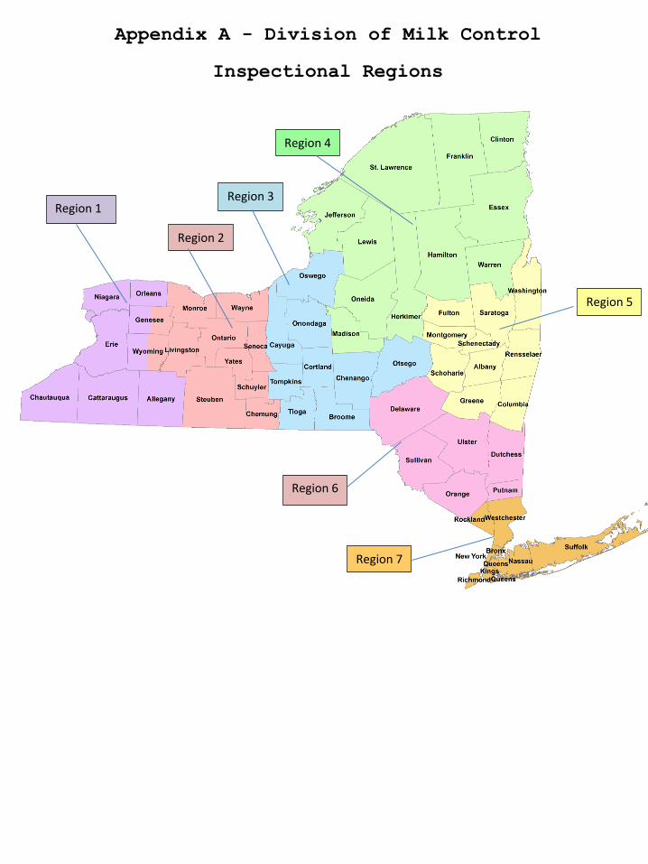
Submit hard copies of the completed application(s) and required
information as follows: two copies to the Dairy Products Specialist 2
(Regional Supervisor) for the County the producer farm is located in
and one copy to the Certified Milk Inspector (CMI) representing the
milk cooperative / handler. See map in Appendix A for counties and
regions. Mailing addresses for Division of Milk Control staff can be
obtained by contacting our office at (518) 457-1772.
The applications are electronically fillable and may be submitted via
email. If this route of submission is chosen then it will be
necessary to submit all of the required information in this manner.
Files must be in Portable Document Format (PDF). Plan drawings must
be legible when viewed by computer. Otherwise, it shall be necessary
for our Department to request hard copies if plan drawings are not
legible. Email addresses may be obtained by contacting our office as
stated above.
Applications and plans are reviewed by the CMI representing the milk
cooperative in consultation with a Dairy Products Specialist (DPS)
representing the Division of Milk Control. Applications and plans must
be approved by the DPS prior to starting any installation. While it is
recommended that the producer, fabricator, CMI and representatives of
this Department be brought together in the earliest stages of
planning, all applications must be submitted no less than 30 days
prior to the anticipated date of installation. Please allow 10
business days for the review of plans and response from this
Department. A variance from this timeframe requirement can be given
in the case of a documented emergency. A variance will only apply to
modifications and all related information would need to be received in
a timely manner.

3
All applications must be accompanied by a detailed legible line
drawing of the milking system indicating the following items when
present:
1. Bulk milk
Tank
5. Floor drain 9. Receiver
Group
13. Milk
filters
17. Wash
Manifold
21. Air Blow
Assembly
2. Double wash
vat
6. High Point 10. Weigh Jars 14. Vacuum
pump
18. Reclaimed
water tank
22. Pre-rinse
divert valve
3. CIP
Pipeline vat
7. Vacuum test
port
11. Pipeline
inspection
port
15. Wash flow
(blue line)
19. Backflow
prevention
device
4. Hand wash
sink
8. Air
Injector
12. Milk Pre-
cooler
16. Milk flow
(red line)
20. Chart
Recorder
All applications must be accompanied by complete information with
regard to hot water requirements for equipment washing and cooling
information for milk cooling. Please see subsequent sections for more
detailed information.
References for Installers
State of New York
Dept. of Agriculture & Markets
Division of Milk Control
10B Airline Drive
Albany, NY 12235
518-457-1772
1-800-554-4501
www.agriculture.ny.gov
ASABE Standards
• ANSI/ASABE AD5707:2007
• ANSI/ASABE AD6690:2007
• ANSI/ASABE AD20966:2007
American Society of
Agricultural Biological
Engineers
2950 Niles Rd
St Joseph MI 49805
269-429-0300 or 800-606-2304
Email: [email protected]
Web site: www.asabe.org
3-A Sanitary Standards and
Accepted Practices
3-A Sanitary Standards, Inc.
6888 Elm Street Suite 2D
McLean, Virginia 22101
703-790-0295
Guidelines on milking parlors,
milk pre-coolers, water heater
sizing, etc.
The Dairy Practices Council
19 Titus Court
Richboro, PA 18954
Tel/Fax 215-355-5133
Email: [email protected]
Web site: www.dairypc.org
Welding Guidelines, AWS D:18.1
and D:18.2
American Welding Society
8669 NW 36 Street, # 130
Miami, Florida 33166-6672
Phone: 800-443-9353 or 305-443-
9353
www.aws.org
4
Design, Fabrication and Installation of Milking and Milk
Handling Equipment
All milking and milk handling equipment shall be designed and
fabricated to meet or exceed the requirements as stated in the 3-A
Sanitary Standards, Inc.’s “3-A Accepted Practices for the Design,
Fabrication and Installation of Milking and Milk Handling Equipment,
Number 606-05” and the American Society of Agricultural Engineers’
“ANSI/ASABE AD5707:2007 (JAN2011) Milking Machine Installations –
Construction and Performance”.
Installation of equipment and construction of milking facilities shall
be completed with due consideration to all sanitation requirements of
the 1 NYCRR Part 2 Regulations and the Pasteurized Milk Ordinance
(PMO).
An analysis of the milking system must be completed as outlined in the
ASABE Standard “ANSI/ASABE AD6690:2007 (JAN 2011) Milking machine
installations — Mechanical tests” or as described in the National
Mastitis Council (NMC) publication “Procedures for Evaluating Vacuum
Levels and Air Flow in Milking Systems” prior to using the system for
milking. A copy of the report must be left at the producer facility
and be made available for review by the Certified Milk Inspector
representing the cooperative handling the producer milk as well as
other regulatory agencies.
In addition to the standards referenced above the following items
shall be considered or required where stated. See applicable
information in the following for additional requirements regarding
Automatic Milking Installations and Direct Loading operations.
Welded Pipelines
Good manufacturing practices recommend that a sample weld be made at
the start of each days welding, dated with the welder’s identification
and made available at the producer location for evaluation. Welds on
pipelines and other equipment must be inspected by a CMI representing
the cooperative handling the producer milk during the installation.
Welds should be made and reviewed according to AWS D18.1 Specification
for Welding Austenitic Stainless Steel Tubing Systems in Sanitary
(Hygienic) Applications and AWS D18.2 Guide to Weld Discoloration
Levels on Inside of Austenitic Stainless Steel Tube.
Standard lengths of pipe should be used as much as possible to
minimize the number of gaskets and welds.

5
-
The pipeline should be of uniform diameter. If a change in diameter
is required then proper fittings must be installed to allow for proper
drainage.
Rolled-on fittings may be used when modifying or repairing existing
on-site farm milk handling systems.
If new milk line or wash line is installed / expanded by the addition
of new piping then those fittings must be welded.
When a previously used pipeline is moved to a different facility then
any repairs or modifications to that pipeline must be welded.
Receiver Group
The receiver cannot be welded into the system.
Milk probes must be removable without disassembly of the receiver
group. The receiver group must be installed in an area that is
cleanable and provides protection from dust or animal droppings.
Installation of the receiver group in the milkhouse is preferable.
Installation in a milking parlor is acceptable if the equipment is
located to provide protection from contamination, is accessible and a
means of inspection can be demonstrated. The equipment cannot be
installed under a cow platform or in a recessed area which would
require equipment disconnection and removal for routine maintenance
and inspection.
Installation of a receiver group in a pit is permitted if a trapped
floor drain is provided in the pit and a means for inspection can be
demonstrated.
A separate room for the receiver group is permitted. This room must be
constructed with washable walls and ceilings, a concrete floor with
drain, adequate lighting, proper ventilation and at least cold water
under pressure. This room must be large enough to provide room for the
required equipment and for maintenance and inspection.
Vacuum System and Milk Line Sizing
Vacuum systems and milk lines must be designed and sized according to
“ANSI/ASABE AD5707:2007 (JAN2011) Milking Machine Installations –
Construction and Performance”. See Appendix for Milking System Sizing
tables.
Vacuum requirements other than those asked for on the DMC 1517
application must be attached separately to the application.
6
Pipeline Clean in Place (CIP) Systems
In the State of New York all on-farm pipeline CIP systems are required
to be fully automatic. A fully automatic wash system is defined as a
wash system which proceeds through a series of pre-rinse, wash and
post rinse cycles of predetermined length without manual intervention
after initial activation.
A pre-rinse divert valve shall be provided to divert the first rinse
to drain. Pre-rinse divert valves cannot be piped directly into a
sewer drain. A sufficient air gap must be provided.
Water fill pipes cannot be piped below the flood rim of wash vats.
Wash vat drains may be piped directly to sewer systems.
Where manual cleaning of equipment is required, a 2 compartment wash
vat must be provided in the milkhouse to wash and rinse equipment.
The current in use cleaning program, including water hardness and
detergent and sanitizer concentration must be posted in the milkhouse.
The cleaning instructions must be accurate for the chemicals currently
available in the milkhouse.
It is important that cleaning programs are designed to include a
sanitizing step. Often times we find systems that do not include a
sanitizing step. Systems that do not include sanitizer are considered
to be in violation of the requirements of the PMO.
Air injectors shall be installed in the milkhouse or an approved
clean-in-place parlor.
Air injectors installed in the milking parlor shall be equipped with
an acceptable filter.
The installation of air injectors in a milking barn or animal housing
area is not allowed.
Hot water
Each milkhouse and milking facility shall be provided with facilities
for heating water in sufficient quantity and to such temperatures for
the effective cleaning of all equipment and utensils.
Hot water heating systems used for Clean in Place (CIP) wash systems
must be able to fill the wash vat or sink with no less than 160°F
water in 10 minutes.
7
The installer or producer shall determine the water heating capacity
needed. Guidance for sizing water heating systems can be obtained from
The Dairy Practices Council publication number 58, "Guidelines for
Sizing Dairy Farm Water Heater Systems.”
A worksheet showing how the minimum volume of hot water necessary for
each cycle (pre-rinse, wash, post rinse, sanitize) was determined must
be attached to the submitted application.
Heat recovery systems that are equipped with a heating element may be
used when determining hot water requirements.
Heat recovery systems that are not equipped with a heating element
cannot be used to determine hot water needs. They may be incorporated
into the system but the system cannot be downsized based on an assumed
constant temperature of preheated water.
Supplemental heating systems (e.g. outdoor wood furnaces, solar
systems) may be used for pre-heating water that is feeding a
dedicated, automatic water heating system.
For on demand water heating systems, the outlet flow data and the
manufacturer’s installation requirements must be submitted with the
application along with a worksheet showing how the size and flow of
the unit will provide the needed amount of hot water.
Compressed Air
Compressed air systems used for product contact, such as air blow
assemblies, must be installed per the PMO Appendix H, II. Air for
Drying Equipment and Air Under Pressure - Direct Contact with Milk and
Milk Products and Milk Product-Contact Surfaces. Further detail can be
found in 3-A Sanitary Standards, Inc. “3-A Accepted Practices for
Supplying Air Under Pressure in Contact with Milk, Milk Products and
Product Contact Surfaces, Number 604-“.
All air blow assemblies must be equipped to utilize disposable point
of use filter media and installed to allow disassembly for maintenance
and inspection.
Compressed air systems must be protected to preclude contamination of
the air piping system.
There shall be no lines installed that by-pass the filter assemblies
on product contact compressed air lines unless provisions are made to
provide proper filtering on the by-pass line.

8
Clean and dry storage located convenient to point of use must be
considered for air blow filter storage.
Farm Milk Cooling and Storage Systems
All farm milk cooling and storage systems shall be designed,
fabricated and installed to meet or exceed the 3-A Sanitary Standards,
Inc.’s 3-A Accepted Practices for Farm Milk Cooling and Storage
Systems Number 611-.
Installation of equipment and construction of milk storage facilities
shall be completed with due consideration to all sanitation
requirements of the 1 NYCRR Part 2 Regulations and the Pasteurized
Milk Ordinance (PMO).
In addition to the standards referenced above the following items
shall be considered or required where stated.
Pre-Cooler Installation
The installation of pre-coolers, all types, shall comply with 3-A 606-
05.
Pre-coolers shall drain completely and automatic drains shall be
provided where needed. Multiple pass coolers shall be designed to
allow drainage of all the passes that can trap water.
Install pre-coolers to accommodate access for inspection and cleaning.
Provide any tools needed for disassembly near the cooler.
There shall be no by-pass lines installed on the milk inlet to the
milk outlet lines of the pre-cooler in an effort to increase cleaning
solution flow rate. Pumps and heat exchangers must be sized correctly
to allow proper flow of cleaning solutions through the heat exchanger
to provide for proper cleaning.
A sanitary sampling valve located in an accessible location and
properly close coupled to the main line shall be located on
recirculated cooling systems.
Bulk Milk Cooling Tanks, Storage Tanks and Storage Silos
Construction
Bulk milk cooling tanks, storage tanks and storage silos shall meet
the sanitary construction requirements of 3-A® Sanitary Standards for
Farm Milk Cooling and Holding Tanks, Number 13-11 and 3-A® Sanitary
Standards for Farm Milk Storage Tanks, Number 30-01 as applicable.
9
Used tanks must be inspected for condition and proper sanitary design
prior to approval of application.
Installation
Farm bulk tanks shall be installed in a milkhouse meeting all
applicable requirements of 1NYCRR Part 2 and the most current revision
of the PMO.
Safe and suitable access to the tank opening shall be provided when
climbing ladders or steps are necessary for normal operation.
The foundation for a farm milk tank shall be constructed with due
consideration of frost penetration and shall be of sufficient strength
to support the fully liquid-laden tank without change of level (1NYCRR
Part 220.7).
The distance between the top of the milk tank and the ceiling shall
not be less than 36 inches. The minimum acceptable dimensions for a
recessed ceiling are five feet by five feet, and the recessed area of
the ceiling shall be positioned off center in such a manner that the
maximum area is available for placing the test equipment. This
subdivision shall apply only to farm milk tanks installed on or after
March 1, 1979 (1NYCRR Part 220.7).
The above clearance requirement is a requirement of the NYS Division
of Weights and Measures to allow for proper utilization of calibration
equipment. It is recommended that any ceiling recessed to meet the
requirement be cleared in advance with the local County Office of
Weights and Measures representative who will be responsible to
calibrate the tank when the installation is completed.
Bulk milk storage tanks shall be positioned so that there is not less
than 30 inches of working clearance on all sides with the following
exception:
There shall be not less than 36 inches of unobstructed clearance on
the outlet valve side, the wash vat side and the cleaning side.
Clearances shall be measured horizontally from the widest part of the
body of the tank and not from any projecting part or accessory
fitting, except measurement shall be from projecting parts of the tank
or accessory fittings that extend the entire length or width of the
tank.
Bulk tanks shall be located so that the outlet valve is not less than
18 inches from any floor drain.
10
Bulk tanks shall not be located over the top of any floor drain.
A bulk tank may be installed so that a portion of the bulk tank
protrudes through the wall of a milkhouse, provided that all bulk tank
openings are located inside the milkhouse.
Agitator seals, other than weatherproof agitator seals meeting the
requirements found within 3-A® Sanitary Standards for Farm Milk Cooling
and Holding Tanks, Number 13-11, shall be located inside the
milkhouse.
Lights suitable for illuminating the interior of the tank and the
exterior portion of the tank in the vicinity of the measuring rod and
manhole shall be permanently installed in the milkhouse.
Single manhole tank installations require a permanently installed
light which can be extended through the manhole to illuminate the
interior of the tank for inspection and special maintenance.
All single manhole tanks are required to have an automatic wash
system, manual washing is not acceptable.
Sampling Milk from Bulk Tanks
Bulk tanks and/or vertical storage silos equipped with aseptic septum
type samplers (e.g. QMI) or any non-traditional(e.g. pet cock style
sampling valve) shall have a Standard Operating Procedure (SOP) for
sampling developed by the milk cooperative’s CMI and then approved by
this Department.
The CMI shall make arrangements to assure that anyone responsible for
using such sampling devices has been trained on proper use and that
equipment and supplies are properly maintained.
All SOPs shall be posted in the milk house.
Temperature Recording
All farm bulk milk tanks manufactured after January 1, 2000 shall be
equipped with an approved temperature recording device in accordance
with Item 18r of the most current revision of the PMO.
Chart recorders, when required or utilized, shall be located to
provide protection to the equipment and to allow ease of access for
both the producer and regulatory agency. Temperature recording chart
location shall be approved by the CMI and producer prior to
installation.

11
Milkhouse – General Recommendations
In addition to the requirements of the 1 NYCRR Part 2 regulations and
the PMO, the following is offered as extra guidance for milk house
operations. The following items are best addressed well in advance to
completion of plans. A collaboration between producer, installer, CMI,
Milk Haulers, NYS and subcontractors will provide for a more
functional and longer lasting facility.
Proper ventilation in milk houses is often overlooked and must be
considered on all installations. Proper insulation and ventilation
will reduce odors, condensation and growth of molds and algae in the
milk house. A minimum ventilation rate of 4 air changes per hour is
recommended by Dairy Practices Guideline #41.
In an effort to increase the life span of floors and walls in the milk
house consideration must be given to directing all drain water into
drains rather than run the water across a floor. This is especially
true of CIP drain water from tanks, wash vats and other equipment.
When running pipes to floor drains be sure to maintain a minimum air
gap of 1 inch above the drain.
Consideration must be made for the storage of pails, brushes and other
appurtenances used for manually cleaned items. Open shelving and
hooks have been used successfully for these items.
Clean, covered and dry storage space must be provided for milk
filters, air blow filters, paper towels used for teat prep and other
related single service articles.
A sampling workspace for the milk hauler should be provided in the
milk house. This could be a small, wall mounted fold down shelf or
table that will allow the hauler to place sampling items, notebook,
etc. The shelf or table should be fabricated of easily cleanable
material that will withstand humidity changes often found within the
milk house.
Automatic Milking Installations (AMI)
As defined in the PMO: “AUTOMATIC MILKING INSTALLATION (AMI): The term
Automatic Milking Installation (AMI) covers the entire installation of
one (1) or more automatic milking units, including the hardware and
software utilized in the operation of individual automatic milking
units, the animal selection system, the automatic milking machine, the
milk cooling system, the system for cleaning and sanitizing the
automatic milking unit, the teat cleaning system, and the alarm
12
systems associated with the process of milking, cooling, cleaning and
sanitation.”
AMI systems shall be installed in accordance with all applicable
requirements of Section 7 and Appendix Q of the PMO. FDA issued a
Memorandum of Information M-I-14-8 dated April 21, 2014. This
document was issued as information and guidance for interpretation of
the requirements of Appendix Q.
The milk house and other portions of the installation shall meet all
of the applicable requirements of Section 7 of the PMO as well as
those in this document.
Applications for Installation
The DMC 1517 as well as the DMC 1537 Supplemental Application for
Automatic Milking Installation (AMI) must be completed in full.
All applications must be accompanied by a detailed, color coded
legible line drawing of the milking system indicating the following
items when present, in addition to the items required in the
application form DMC 1517.
33. AMI Location 35. Positive Air
Ventilation System
37. Operator Traffic
Flow
39. Water protection
34. Milk Storage 36. Check Valves 38. Milk Line Air Blow
Assemblies
40. Milk tank blocking
valves layout
The application form is very specific with regard to what information
must be attached to each application.
With regard to the PMO Appendix Q and M-I-14-8 the following is
offered as further clarification:
Compressed Air Systems
All air blow assemblies for milk line evacuation on all automatic
milking units must be equipped with a disposable point of use filter
in accordance with Appendix H of the most current revision of the PMO.
This would be a filter located at the air blow assembly. An easily
accessible location must be considered for any air blow added to a
unit during the installation to allow for inspection and maintenance.
Replacement filters must be stored convenient to the operation and to
preclude contamination.
Cleaning Systems and Hot Water
Most AMI units have on-board water heating capabilities for washing
the automatic milking unit and the milk line to the milkhouse. In
13
most cases, a separate water heating system and wash system is needed
for cleaning the bulk milk storage tank. Hot water requirements and
water heating capacity information must be attached to all
applications as requested in the DMC 1517 application.
Separation of Milk and CIP Solution (Fail Safe Valve System)
A detailed schematic showing the layout of the fail safe valve set-up
at the bulk milk storage tank must be submitted with the application.
The layout schematic submitted shall be for the particular
installation that application is being submitted for and not a generic
suggested manufacturer’s design.
Operation of all fail safe valve systems must be verified through
testing by the installer or manufacturer’s technician in consultation
with the Certified Milk Inspector and representatives of the Division
of Milk Control.
The use of butterfly valves is prohibited in the block and bleed
system design. These valves are not approved for CIP cleaning.
Positive Ventilation Air
Item 12r of Appendix Q of the PMO requires that positive ventilation
air be supplied to the automatic milking unit room.
The ventilation system is required to operate whenever the system is
cleaning (including full system washes and partial washes) and may
need to run during milking to minimize odor, dust and/or pests.
The air for this system shall come from outside the cattle housing
area and shall be as clean and dry as practical.
It will be necessary for the installer and / or the producer to design
and install a system which provides greater air pressure within the
automatic milking unit room than that of the animal housing or free-
stall area.
A detailed drawing and description of such a system must be submitted
with the application.
At this time there is no singular system guidance for how a positive
air ventilation system should be designed. However, from continual
review of systems and research we have found that systems designed for
less than 40 air changes per hour (ACH) are not adequate. See
Appendix C for formulas to determine ACH.

14
Inspectional Areas of Concern
The installer or manufacturers technician must review the inspection
procedures and testing procedures for the AMI system in use with the
cooperative’s Certified Milk Inspector. This training must include
which areas of the unit may be disassembled and / or tested, without a
technician present, during routine inspections. These areas should be
documented.
AMI Documentation
There are several documents that must be available at the producer
facility for review by Regulatory agencies. It is recommended that a
binder of information be created and made accessible. It is also
acceptable to create an electronic file so long as it is accessible to
the Certified Milk Inspector without the producer or manufacturer
technician present. The following needs to be available:
The FDA issued M-I document specifying acceptance of the teat
preparation protocol for the AMI unit.
The manufacturers testing and verification procedures for each of the
fail safe valve system arrangement(s).
Instructions for accessing milk storage temperature records and
equipment cleaning records. These instructions should include screen
shots and key stroke instructions where appropriate.
The milk hauler pick up procedure. These instructions should also
include screen shots and key stroke instructions where appropriate.
Direct Tanker Loading Operations
Direct tanker loading is that process whereby milk is directly loaded
onto a transportation tanker from the milking system through by-
passing the use of a farm bulk milk tank(s) and / or silo(s).
All equipment installed and facilities constructed for use in direct
tanker loading operations shall meet all the applicable requirements
of Section 7, particularly Item 5r and Appendix B of the PMO as well
as those found in this document.
Applications for Installation
The DMC 1517 as well the DMC 1543 Supplemental Application for Direct
Tanker Loading Milking Operation must be completed in full.
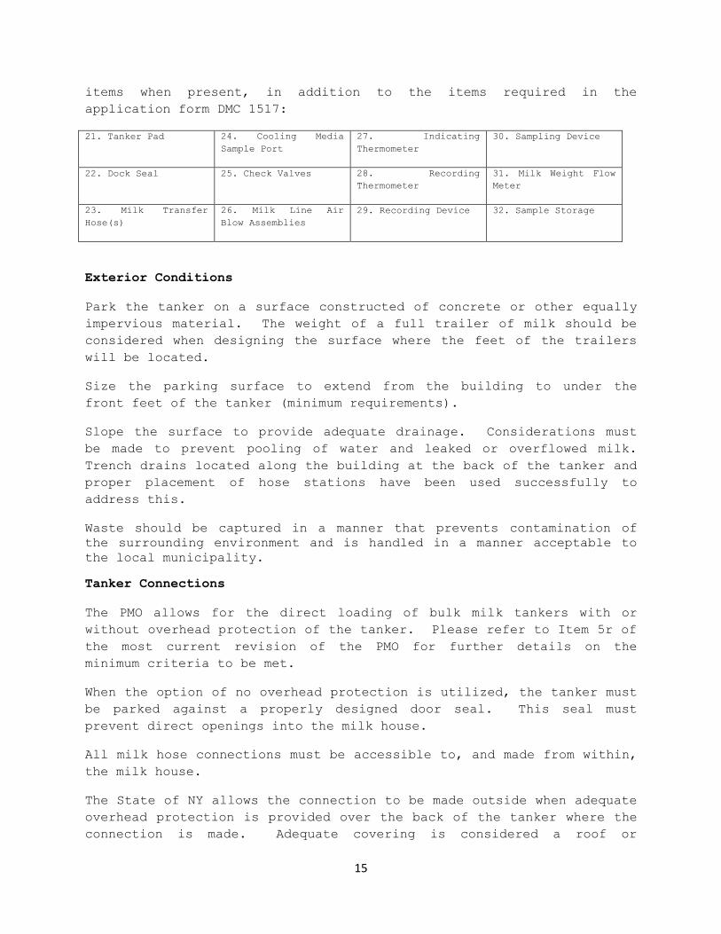
All applications must be accompanied by a detailed, color coded
legible line drawing of the milking system indicating the following
15
items when present, in addition to the items required in the
application form DMC 1517:
21. Tanker Pad 24. Cooling Media
Sample Port
27. Indicating
Thermometer
30. Sampling Device
22. Dock Seal 25. Check Valves 28. Recording
Thermometer
31. Milk Weight Flow
Meter
23. Milk Transfer
Hose(s)
26. Milk Line Air
Blow Assemblies
29. Recording Device 32. Sample Storage
Exterior Conditions
Park the tanker on a surface constructed of concrete or other equally
impervious material. The weight of a full trailer of milk should be
considered when designing the surface where the feet of the trailers
will be located.
Size the parking surface to extend from the building to under the
front feet of the tanker (minimum requirements).
Slope the surface to provide adequate drainage. Considerations must
be made to prevent pooling of water and leaked or overflowed milk.
Trench drains located along the building at the back of the tanker and
proper placement of hose stations have been used successfully to
address this.
Waste should be captured in a manner that prevents contamination of
the surrounding environment and is handled in a manner acceptable to
the local municipality.
Tanker Connections
The PMO allows for the direct loading of bulk milk tankers with or
without overhead protection of the tanker. Please refer to Item 5r of
the most current revision of the PMO for further details on the
minimum criteria to be met.
When the option of no overhead protection is utilized, the tanker must
be parked against a properly designed door seal. This seal must
prevent direct openings into the milk house.
All milk hose connections must be accessible to, and made from within,
the milk house.
The State of NY allows the connection to be made outside when adequate
overhead protection is provided over the back of the tanker where the
connection is made. Adequate covering is considered a roof or
16
overhang that extends no less than 8 feet from face of the building.
The cabinet on the back of the tanker is not considered adequate
protection.
When this option is utilized and the milk line is stubbed out of the
milk house, the CIP return loop must be made as short as possible and
this loop must be hard piped. Provisions must be made for the flexible
transfer hose to be washed and hung off the floor for storage inside
the building or within an enclosure found to be acceptable by the CMI
and NYS Dept. of Agriculture & Markets.
Means shall be provided to properly wash the check valve assembly used
for filling each tanker.
Milk Cooling
Milk shall be cooled to 45°F (7.2°C) or colder prior to it entering
the tanker.
Provide all BTU removal requirements and total cooling capacity for
the proposed cooling system with the submitted application.
Properly design and operate the cooling media system to prevent
contamination of the milk supply.
Water used to cool the milk supply shall be from a safe and approved
source.
Use food or pharmaceutical grade coolant additives that are non-toxic
and comply with 21 CFR 184.1666.
Provide a sanitary sampling port or other sampling access to the
cooling media system.
Install a milk temperature recording thermometer probe downstream from
the heat exchanger in a sanitary well in the milk line.
Recording thermometers and / or electronic temperature recording
systems must be installed in accordance with Item 18r of the most
current revision of the PMO.
Install a milk temperature indicating thermometer as close as possible
to the temperature recording probe to verify accuracy of the recording
thermometer.
There shall be a means provided to check thermometers for accuracy.
A Standard Operating Procedure (SOP) outlining the procedure for
making such accuracy checks must be developed by the CMI representing
17
the milk cooperative and approved by the Dept. of Agriculture and
Markets.
Thermometers must be verified for accuracy (within ± 2°F) every six
months by the dairy cooperative CMI and properly documented (document
in a log or on chart) and this documentation must be maintained on
file at the farm for review by regulatory agencies.
A suggestion is to maintain a small jar or vial of mineral oil in the
sample refrigerator that can be utilized by the CMI to conduct
temperature verifications when milk is not running through the milk
line.
The NYS Department of Agriculture & Markets allows the digital readout
on the chart recorder to be considered as an indicating thermometer,
as per FDA M-I-03-13.
Milk Sampling at the Farm
All persons responsible for obtaining milk samples to be used for
regulatory purposes must hold a NYS Milk Receiver’s License from the
NYS Dept. of Agriculture & Markets, Division of Milk Control.
The milk shall be sampled in a manner to preclude contaminating the
milk tanker or the milk sample.
Sampling at the farm must be done according to a properly prepared
Standard Operating Procedure (SOP).
Milk samples may be obtained directly from a properly agitated tanker
located in a suitable shelter. The suitable shelter shall meet the
construction, lighting and drainage requirements of a milkhouse. The
milk tanker shall be agitated in accordance with the criteria outlined
in Standard Methods for the Examination of Dairy Products, Section
3.042 B.
Alternatively, milk samples may be obtained by use of an approved in-
line milk sampling device installed on the milk pipeline system. In-
line sampling devices must be an approved device, installed and
maintained as outlined in the FDA document M-I-06-6.
Detailed SOPs must be submitted and approved by the CMI and the NYS
Dept. of Agriculture & Markets for that sampling method which is
utilized. SOPs should be drafted and submitted for review will in
advance of the start of any operation in expectation that several
drafts may be necessary before final approval.
18
The FDA document M-I-06-6 contains generic SOPs for the three
validated and accepted in-line sampling units. These SOPs may be used
as a base SOP with necessary edits made to create a SOP unique to the
operation being proposed.
All persons responsible for the collection of samples must be trained
by the CMI and licensed by this Dept. as stated above.
This SOP must also outline the proper cleaning, sanitizing and
maintenance of any in-line sampler in use.
Anyone responsible for maintaining or cleaning a sampler, including
anyone changing sample needles, bags, bottles, etc., must be trained
according to this SOP.
All training must be documented and on file at the producer facility.
An area within the milk house should be considered for a sampling
station to allow proper taking of samples. See section on Milk house
considerations.
Methods and Means to Determine Milk Weight
The methods and means that will be used to determine the weight of the
milk on the milk tank truck will be specific to each installation.
Each individual installation protocol shall include a description of
the method and means used to make this determination.
The following is provided by the NYS Dept. of Agriculture & Markets
Bureau of Weights & Measures to establish the requirements when using
an in-line flow meter to measure official milk weights on the farm.
Direct bulk milk metering systems used for commercial transactions
shall meet the following requirements:
The measuring device shall meet the type approval requirements as
described in 1 NYCRR part 220.1.
The appropriate municipal director of weights and measures is notified
before use.
The measuring device and related accessories shall be installed,
tested and maintained as per the requirements of National Institute of
Standards and Technology (NIST) Handbook 44 “Specifications and
Tolerances for Commercial Weighing and Measuring Devices”. These
requirements include:
1. Installation in accordance with the manufacturer’s instructions,
including instructions marked on the device. Installation must be

19
in a fixed location so that neither its operation nor its
performance will be adversely affected by the foundation,
supports, or any other detail of the installation.
2. A primary indicating element. In NYS it is customary to purchase
and sell milk by the pound based on 8.6 lb. /gal, therefore, the
indicating element should display in pound units.
3. Effective vapor elimination, automatic in operation, to ensure
air is eliminated from the milk before passing through the
measuring device.
4. The vapor eliminator must be positioned or installed such that it
cannot be easily emptied between uses and maintains a flooded
condition during measurements.
5. A provision for security (e.g. data change audit trail) or for
applying a physical security seal.
6. An adequate provision to ensure no liquid can be diverted from
the supply tank to the receiving tank without being measured.
7. An effective provision to ensure the discharge rate is maintained
within the maximum and minimum flow rates for the meter.
8. Marking on the air eliminator the volume of product necessary to
flood the system, “flood volume”, when dry (if applicable).
9. Marking on the primary indicating element and the delivery record
the conversion factor (8.6 lb. /gal.).
10. Recording on the delivery ticket, credit for flood volume for
each transfer affected.
20
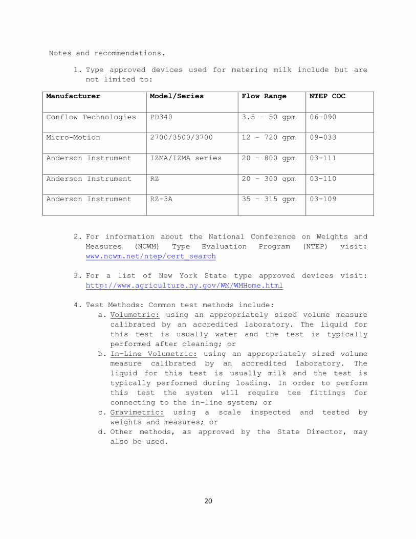
Notes and recommendations.
1. Type approved devices used for metering milk include but are
not limited to:
Manufacturer Model/Series Flow Range NTEP COC
Conflow Technologies PD340 3.5 – 50 gpm 06-090
Micro-Motion 2700/3500/3700 12 – 720 gpm 09-033
Anderson Instrument IZMA/IZMA series 20 – 800 gpm 03-111
Anderson Instrument RZ 20 – 300 gpm 03-110
Anderson Instrument RZ-3A 35 – 315 gpm 03-109
2. For information about the National Conference on Weights and
Measures (NCWM) Type Evaluation Program (NTEP) visit:
www.ncwm.net/ntep/cert_search
3. For a list of New York State type approved devices visit:
http://www.agriculture.ny.gov/WM/WMHome.html
4. Test Methods: Common test methods include:
a. Volumetric: using an appropriately sized volume measure
calibrated by an accredited laboratory. The liquid for
this test is usually water and the test is typically
performed after cleaning; or
b. In-Line Volumetric: using an appropriately sized volume
measure calibrated by an accredited laboratory. The
liquid for this test is usually milk and the test is
typically performed during loading. In order to perform
this test the system will require tee fittings for
connecting to the in-line system; or
c. Gravimetric: using a scale inspected and tested by
weights and measures; or
d. Other methods, as approved by the State Director, may
also be used.
Region 1
Region 2
Region 3
Region 4
Region 5
Region 6
Region 7
Region 5
Region 7
Appendix A - Division of Milk Control
Inspectional Regions
48 mm (2 in.) 2 3 3 4 60 mm (2.5 in.) 6 9 *(9) *(9) 73 mm (3 in.) *(9) *(11) *(13) *(16)
50 2 in. 2 3 3 3 3 3 70 3 3 3 3 3 3 3
100 3 3 3 3 4 4 4 150 4 4 4 4 4 4 4 200 4 4 4 4 4 4/6 6 250 4 4 6 6 6 6 6 300 6 6 6 6 6 6 6 400 6 8 6 6 6 6 6
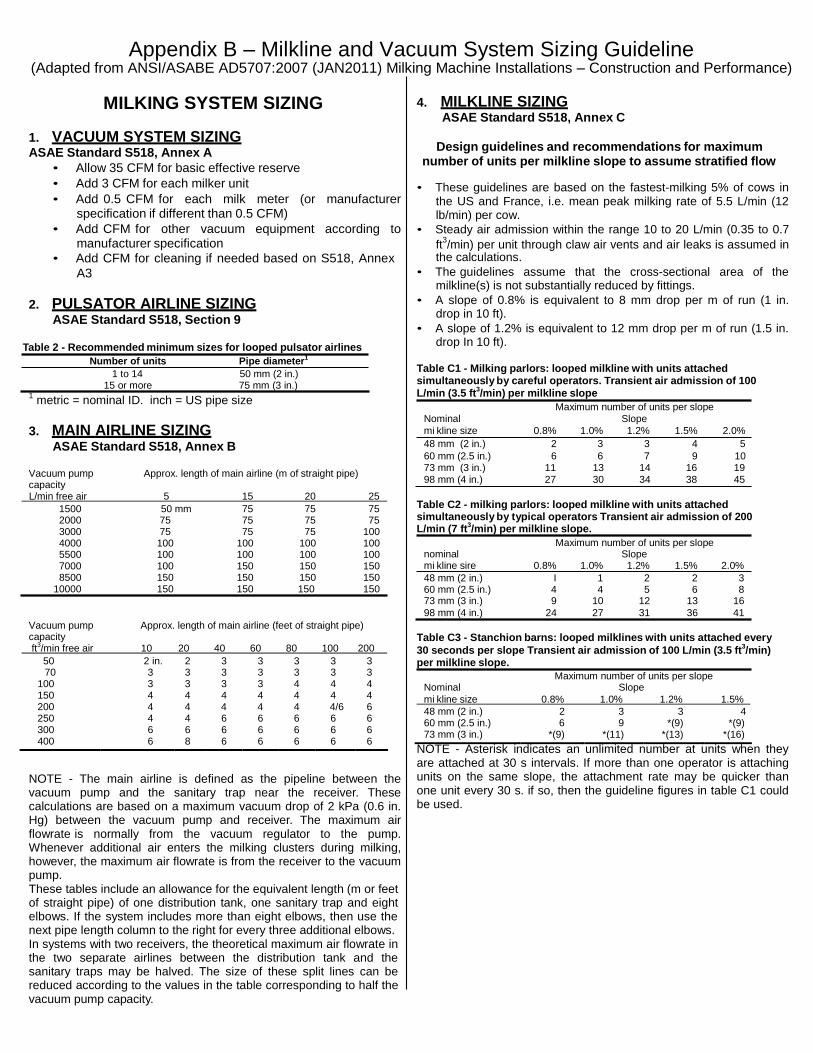
Appendix B – Milkline and Vacuum System Sizing Guideline
(Adapted from ANSI/ASABE AD5707:2007 (JAN2011) Milking Machine Installations – Construction and Performance)
MILKING SYSTEM SIZING
1. VACUUM SYSTEM SIZING ASAE Standard S518, Annex A
• Allow 35 CFM for basic effective reserve
• Add 3 CFM for each milker unit
• Add 0.5 CFM for each milk meter (or manufacturer specification if different than 0.5 CFM)
• Add CFM for other vacuum equipment according to manufacturer specification
• Add CFM for cleaning if needed based on S518, Annex
A3
2. PULSATOR AIRLINE SIZING ASAE Standard S518, Section 9
Table 2 - Recommended minimum sizes for looped pulsator airlines
Number of units Pipe diameter1
1 to 14 50 mm (2 in.) 15 or more 75 mm (3 in.)
1 metric = nominal ID. inch = US pipe size
3. MAIN AIRLINE SIZING ASAE Standard S518, Annex B
4. MILKLINE SIZING ASAE Standard S518, Annex C
Design guidelines and recommendations for maximum
number of units per milkline slope to assume stratified flow • These guidelines are based on the fastest-milking 5% of cows in
the US and France, i.e. mean peak milking rate of 5.5 L/min (12 lb/min) per cow.
• Steady air admission within the range 10 to 20 L/min (0.35 to 0.7
ft3/min) per unit through claw air vents and air leaks is assumed in
the calculations.
• The guidelines assume that the cross-sectional area of the milkline(s) is not substantially reduced by fittings.
• A slope of 0.8% is equivalent to 8 mm drop per m of run (1 in. drop in 10 ft).
• A slope of 1.2% is equivalent to 12 mm drop per m of run (1.5 in. drop In 10 ft).
Table C1 - Milking parlors: looped milkline with units attached simultaneously by careful operators. Transient air admission of 100 L/min (3.5 ft
3/min) per milkline slope
Maximum number of units per slope
Nominal Slope
mi kline size 0.8% 1.0% 1.2% 1.5% 2.0%
48 mm (2 in.) 2 3 3 4 5
60 mm (2.5 in.) 6 6 7 9 10
Vacuum pump capacity
Approx. length of main airline (m of straight pipe) 73 mm (3 in.) 11 13 14 16 19
98 mm (4 in.) 27 30 34 38 45
L/min free air 5 15 20 25
1500 50 mm 75 75 75 2000 75 75 75 75 3000 75 75 75 100 4000 100 100 100 100 5500 100 100 100 100 7000 100 150 150 150 8500 150 150 150 150
10000 150 150 150 150
Table C2 - milking parlors: looped milkline with units attached simultaneously by typical operators Transient air admission of 200 L/min (7 ft
3/min) per milkline slope.
Maximum number of units per slope nominal Slope mi kline sire 0.8% 1.0% 1.2% 1.5% 2.0%
48 mm (2 in.) I 1 2 2 3 60 mm (2.5 in.) 4 4 5 6 8 73 mm (3 in.) 9 10 12 13 16
98 mm (4 in.) 24 27 31 36 41
Vacuum pump capacity
Approx. length of main airline (feet of straight pipe) Table C3 - Stanchion barns: looped milklines with units attached every
ft3/min free air 10 20 40 60 80 100 200 30 seconds per slope Transient air admission of 100 L/min (3.5 ft3/min)
per milkline slope.
Maximum number of units per slope Nominal Slope
mi kline size 0.8% 1.0% 1.2% 1.5%
NOTE - The main airline is defined as the pipeline between the vacuum pump and the sanitary trap near the receiver. These calculations are based on a maximum vacuum drop of 2 kPa (0.6 in. Hg) between the vacuum pump and receiver. The maximum air flowrate is normally from the vacuum regulator to the pump. Whenever additional air enters the milking clusters during milking, however, the maximum air flowrate is from the receiver to the vacuum pump. These tables include an allowance for the equivalent length (m or feet of straight pipe) of one distribution tank, one sanitary trap and eight elbows. If the system includes more than eight elbows, then use the next pipe length column to the right for every three additional elbows. In systems with two receivers, the theoretical maximum air flowrate in the two separate airlines between the distribution tank and the sanitary traps may be halved. The size of these split lines can be reduced according to the values in the table corresponding to half the vacuum pump capacity.
NOTE - Asterisk indicates an unlimited number at units when they are attached at 30 s intervals. If more than one operator is attaching units on the same slope, the attachment rate may be quicker than one unit every 30 s. if so, then the guideline figures in table C1 could be used.

Sheep / Goat Milking System Sizing Guidelines
System Cubic Feet Per Minute
(CFM) (ASME) Liters Per Minute
(LPM)
Bucket Systems : Base 10 280
Per Milking Unit additional 2 56
Vacuum Dumping Station 5 140
Pipeline Systems : Base 25 700
Per Milking Unit Additional 2 56
Pipeline systems require more vacuum to wash than to milk under many circumstances given the reduced airflow per unit needs of the two (2) teat cup claws used in small ruminants. The following is a chart for the minimum airflow needed to wash different size milk lines.
Minimum Vacuum for Cleaning* Line Size CFM LPM
1.5” 25 700
2.0” 40 1120
2.5” 60 1680 * for each loop of pipeline, every additional loop will require approximately 50% more airflow
Main Vacuum Line Sizing
Pump Capacity Length of Main Airline Size of Line Required 50 CFM < 60 feet 2 inch 50 -125 CFM 3 inch > 150 CFM Check Manufacturer
Pulsation Lines
2 inch line Up to 35 units
3 inch line 36 or more units
Best Guidance to Date: Field Studies Still On-Going
Number of Milking Units per Line Slope Inches of
Slope in 10’
Nominal Line Size
1” (.8%) 1.25” (1%) 1.5” (1.2%) 1.75” (1.5%)
Goats Sheep Goats Sheep Goats Sheep Goats Sheep
1.5” 3 5 4 6 4 8 5 9
2.0” 6 10 8 12 10 16 12 16
2.5” 12 24 14 24 16 28 18 32
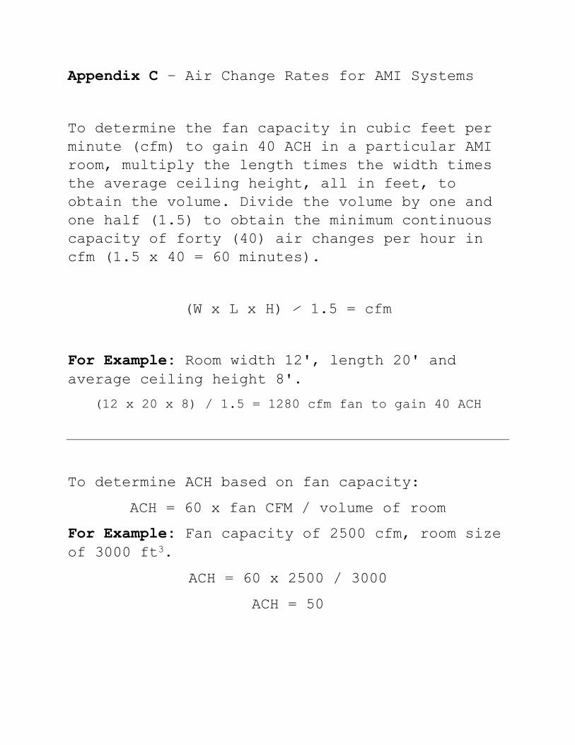
Appendix C – Air Change Rates for AMI Systems
To determine the fan capacity in cubic feet per
minute (cfm) to gain 40 ACH in a particular AMI
room, multiply the length times the width times
the average ceiling height, all in feet, to
obtain the volume. Divide the volume by one and
one half (1.5) to obtain the minimum continuous
capacity of forty (40) air changes per hour in
cfm (1.5 x 40 = 60 minutes).
(W x L x H) ∕ 1.5 = cfm
For Example: Room width 12', length 20' and
average ceiling height 8'.
(12 x 20 x 8) / 1.5 = 1280 cfm fan to gain 40 ACH
To determine ACH based on fan capacity:
ACH = 60 x fan CFM / volume of room
For Example: Fan capacity of 2500 cfm, room size
of 3000 ft3.
ACH = 60 x 2500 / 3000
ACH = 50

Appendix D - Various Manufacturers of Backflow
Preventers and Applications. ASSE 1001 PIPE APPLIED ATMOSPHERIC VACUUM BREAKER
MANF. MODEL NO.
WATTS 288A WILKENS 35 FEBCO 710 & 715 CONBRACO 38-100 & 38-200 CASH-ACME V-101
ASSE 1011 HOSE CONNECTION VACUUM BREAKER
MANF. MODEL NO.
WATTS 8, 8A, 8AC, 8B, 8BC, 8C, NF8, NF8C, 8P, 8FR WILKENS BFP-8 & BFP-8F CONBRACO 38-304, 38P, 38-400, 38-404 CASH-ACME V-3, V-4, VB-222 FABCO 731 series DANFOSS HB8
ASSE 1012 BACKFLOW PREVENTER WITH INTERMEDIATE VENT
MANF. MODEL NO.
WATTS 9-D WILKENS 750 FEBCO 815 CONBRACO 40-400 & 4J-400 CASH-ACME BFP DANFOSS 8200
ASSE 1013 REDUCED PRESSURE PRINCIPLE BACKFLOW PREVENTER
MANF. MODEL NO.
WATTS 009, 909, 995, N995, Z995 WILKENS 375, 975, 975XL, 975BMS/MS,
975XLBMS/MS FEBCO 860,880, 880V, 825, 825YA, 820 CONBRACO 40-200, 40-200U, 40-200Z, 4S RP FLOMATIC RPZE, RPZ IIE
ASSE 1019 VACUUM BREAKER WALL HYDRANTS MANF MODEL NO.
WATTS HY-42, HY-42B, FHB-1 & FHB-2 WILKEN Z1300 series
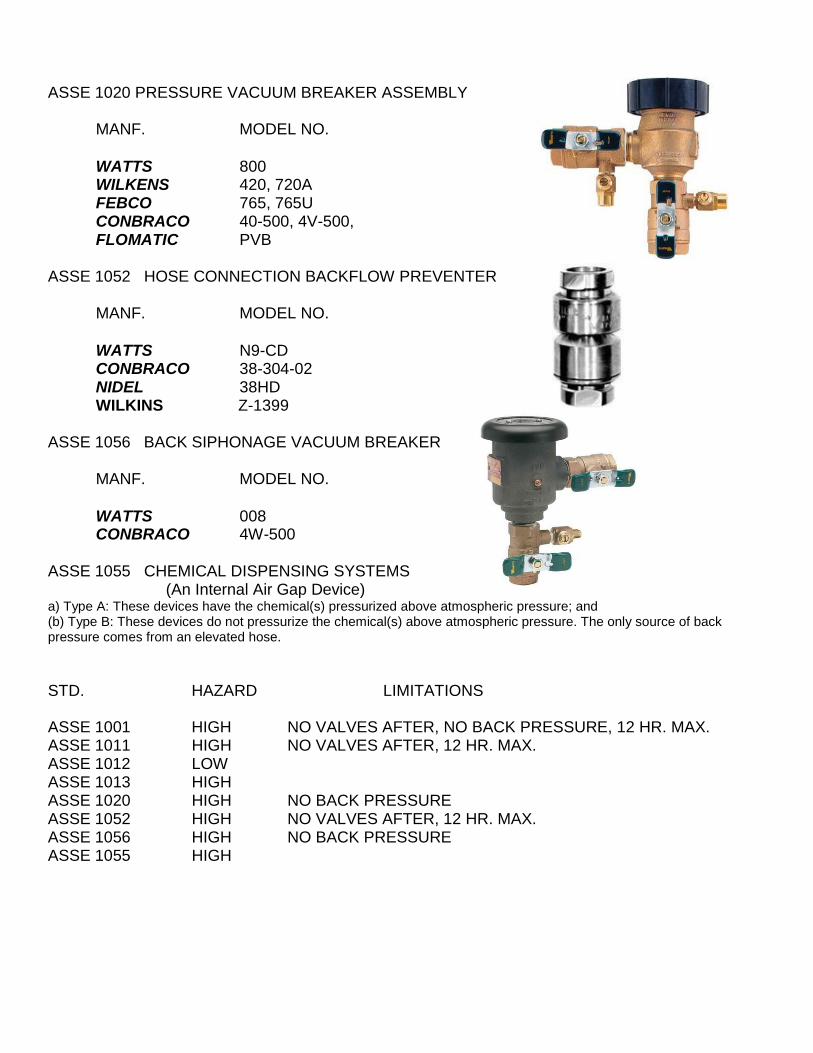
ASSE 1020 PRESSURE VACUUM BREAKER ASSEMBLY
MANF. MODEL NO.
WATTS 800 WILKENS 420, 720A FEBCO 765, 765U CONBRACO 40-500, 4V-500, FLOMATIC PVB
ASSE 1052 HOSE CONNECTION BACKFLOW PREVENTER
MANF. MODEL NO.
WATTS N9-CD CONBRACO 38-304-02 NIDEL 38HD WILKINS Z-1399
ASSE 1056 BACK SIPHONAGE VACUUM BREAKER
MANF. MODEL NO.
WATTS 008 CONBRACO 4W-500
ASSE 1055 CHEMICAL DISPENSING SYSTEMS
(An Internal Air Gap Device) a) Type A: These devices have the chemical(s) pressurized above atmospheric pressure; and (b) Type B: These devices do not pressurize the chemical(s) above atmospheric pressure. The only source of back pressure comes from an elevated hose.
STD. HAZARD LIMITATIONS
ASSE 1001 HIGH NO VALVES AFTER, NO BACK PRESSURE, 12 HR. MAX. ASSE 1011 HIGH NO VALVES AFTER, 12 HR. MAX. ASSE 1012 LOW
ASSE 1013 HIGH
ASSE 1020 HIGH NO BACK PRESSURE ASSE 1052 HIGH NO VALVES AFTER, 12 HR. MAX. ASSE 1056 HIGH NO BACK PRESSURE ASSE 1055 HIGH
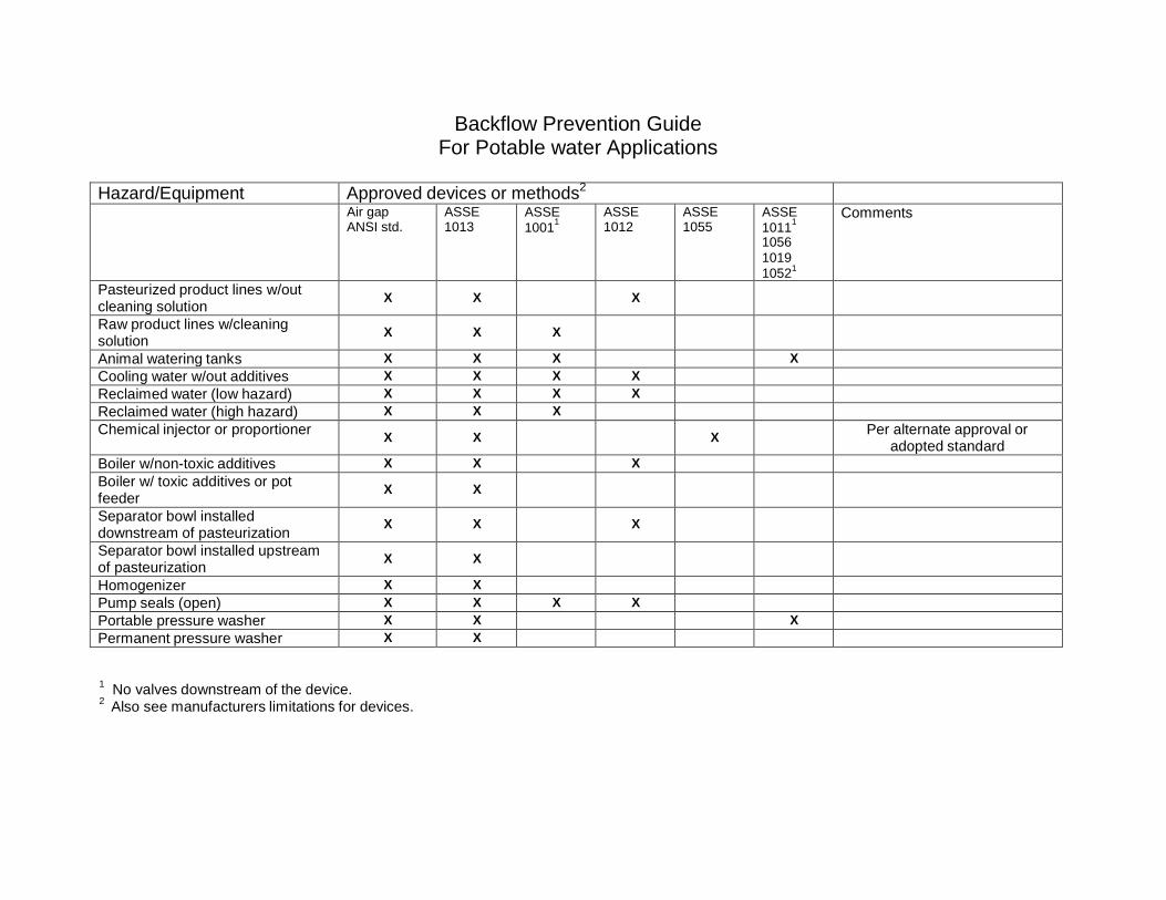
Backflow Prevention Guide For Potable water Applications
Hazard/Equipment Approved devices or methods2
Air gap ANSI std.
ASSE 1013
ASSE
10011
ASSE 1012
ASSE 1055
ASSE
10111
1056
1019
10521
Comments
Pasteurized product lines w/out cleaning solution
X
X
X
Raw product lines w/cleaning solution
X
X
X
Animal watering tanks X X X X Cooling water w/out additives X X X X Reclaimed water (low hazard) X X X X Reclaimed water (high hazard) X X X Chemical injector or proportioner
X
X
X Per alternate approval or adopted standard
Boiler w/non-toxic additives X X X Boiler w/ toxic additives or pot feeder
X
X
Separator bowl installed downstream of pasteurization
X
X
X
Separator bowl installed upstream of pasteurization
X
X
Homogenizer X X Pump seals (open) X X X X Portable pressure washer X X X Permanent pressure washer X X
1 No valves downstream of the device.
2 Also see manufacturers limitations for devices.