
Milk Powder Production -...
64
١ University Of Al- Qadisiya College Of Engineering Chemical Engineering Department Milk Powder Production A Project Submitted To The College Of Engineering Of Al- Qadisiya University In Partial Fulfillment Of The Requirements For The Degree Of Bachelor Of Science In Chemical Engineering Under The Supervision Of Assist. Prof. Dr. Salih A. Salih Done By Zahraa Diaa Faoz Dhafer 2018
Transcript of Milk Powder Production -...
١
University Of Al- Qadisiya
College Of Engineering
Chemical Engineering
Department
Milk Powder Production
A Project Submitted To The College Of Engineering Of
Al- Qadisiya University
In Partial Fulfillment Of The Requirements For The Degree
Of Bachelor Of Science In Chemical Engineering
Under The Supervision Of
Assist. Prof. Dr. Salih A. Salih
Done By
Zahraa Diaa Faoz Dhafer
2018

٢
بسم ا الرمحن الرحيم
وعلمك ما مل تكن تعلم وكان فضل اهللا (
) عليك عظيما
ا العلي العظيمصدق
)١١٣النساء (

٣
Dedication
The beginning, "Thank Allah for the completion of this
project and ask Allah Almighty to benefit him, and then
dedicate this search modest to our families and loved ones
and to all who support us and helped us to complete this
project of professors and singled them Dr. salih A. salih,
and Mr. Husham M. Majeed and the rest of esteemed
professors
who provided us with information We appreciate their
efforts so and them sincerely with the thanks and
appreciation of us.

٤
Acknowledgment
To all those people who
inspired us that we met in
college of engineering

٥
CONCLUSION
The process of manufacturing milk powder is a simple
process that is now widely implemented. Include Thin water
removal at the lowest possible cost under strict sanitary
conditions While retaining all the desirable natural properties of
milk - color, flavor, solubility, Nutritional value.
As for milk production methods, there is only one way to
produce milk powder, which includes liquid milk drying by
using evaporation under a vacuum pressure, in order to
maintain vitamins, proteins and carbohydrates without harming
them, as a result of the use of heat which have a direct impact
on these elements, and also by using spray dryer in order to
obtain a homogenous milk powder.
٦
Contents
Page
Chapter One
Introduction ………………………………….……... 7
Chapter Two
Material Balance ……………………………………… 18
Chapter Three
Energy Balance………………………………………... 30
Chapter Four
Equipment Design …………………………………... .. 35
Chapter Five
Cost estimation …. …………………………………... .. 56
References ………………………………………..…. 64

٧
Introduction

٨
Powdered milk in general
Powder Milk or powdered milk is a
daily product manufactured by
dehydrating liquid milk during several
drying processes until it becomes a
powder.
The purpose of milk drying is to keep it, milk powder has a long
shelf life longer than liquid milk and it does not need to cool.
History and Production
Marco Polo stated ,In the thirteenth century, that the soldiers of
Kublai Khan carried sun-dried milk on their exploratory journeys.

٩
More recently, milk has been dried in thin films on hot rollers. The
oldest patents of this process date back to the beginning of the last
century. This roller drying was the main method of milk powder
production until the 1960s when spray drying became prevalent.
Manufacturing milk powder is a very big business in the 21st
century.
Milk powder manufacturing is a simple process that can be widely
implemented. Production involves the thinnest removal of water at the
lowest possible cost under strict health conditions while retaining all
desirable natural properties of milk such as color, flavor, solubility and
nutritional value.
The percentage of water in skim milk is about 91% and the
percentage of water in whole milk is about 87%. During the process of
producing powdered milk, the milk is boiled under low pressure at low
temperature to remove the water in a process known as evaporation.
To remove further moisture the concentrated milk is sprayed in a
light spray in the hot air and the powder will be formed. We can
manufacture approximately 12 kg of whole milk powder or 9 kg of
skimmed milk powder per 100 liters of whole milk.

١٠
Process of producing milk powder
The traditional milk powder production process begins by taking
raw milk received at the dairy plant and pasteurizing it and separating it
into skimmed milk and cream using a centrifuge cream separator. If full
milk powder is required, a portion of the cream is added to the skim milk
to produce milk with standard fat content (usually 26- 30% fat in the
powder). Excess cream is used to make butter or anhydrous milk fat.
Preheating
Preheating is the next step in the process where the standard milk is
heated to temperatures ranging from 75 to 120 degrees Celsius.
Preheating causes a calculated denaturation of whey proteins in
milk, destroys bacteria, disrupts enzymes, generates natural antioxidants,
and provides heat stability. Milk retains this condition for a specified time
from a few seconds to several minutes (pasteurization: 72 ° C for 15
seconds) .
The exact heating / holding system depends on the type of product
and end use of the product. Preheating is associated with improved shelf
life but reduces solubility. Heating may be indirect (via heat exchangers).

١١
Evaporation
The preheated milk is concentrated in the evaporator in stages or
"effects" of about 9% of the total solids of skimmed milk and 13% of
whole milk to 45-52% of total solids. This is achieved by boiling the milk
under vacuum at temperatures below 72 ° C in the film falling into the
inside of vertical tubes and removing the water as steam. This steam,
which can be pressed mechanically or thermally, is used to heat the milk
in the following example of the evaporator that can be operated at
pressure and temperature lower than the previous effect.
The Evaporators are very noisy because of the amount of water vapor
that travels at high speeds inside the pipes. More than 85% of the water in
the milk can be removed in the evaporator..
Spray Dryer
The spray drying in the Spray dryer is involving the dissolution of
the milk concentration from evaporator to fine droplets. This is done
inside a large drying chamber in hot airflow (up to 200 ° C) using either a
spinning disc spray or a series of high pressure nozzles. Milk droplets are
cooled by evaporation and never reach air temperature. The concentrate

١٢
can be heated before decomposition to reduce viscosity and increase the
energy available for drying.
A large part of the remaining water in the drying chamber is
evaporated, leaving a fine powder containing about 6% of the moisture
content with an average particle size typically <0.1 mm in diameter. The
final or "secondary" drying occurs in a fluid bed, or in a series of such
beds, where hot air is blown through a layer of fluidized powder that
removes water to a degree of moisture content between 2-4%.
Precautions should be taken to prevent fires and vent dust if they
occur in the drying room or elsewhere. Such explosions may be very
dangerous to life, property and markets
Precautions must be taken to prevent fires and to vent dust
explosions should they occur in the drying chamber or elsewhere. Such
explosions can be extremely dangerous to life, property and markets.
Packaging And Storage
Milk powders readily take up moisture from the air, leading to a
rapid loss of quality and caking or lumping. Milk powders are more
stable than fresh milk but there is a need to protect against moisture,
oxygen, light and heat to maintain their quality and shelf life.

١٣
Milk powders easily take moisture from the air, resulting in rapid
loss of quality, and caking or lumping.
The fat can interact with oxygen in the air to give off-flavors,
especially at higher storage temperatures (> 30 ° C) such as those found
in low-lying areas of the tropics.
Milk powder is filled in multi-walled bags lined with plastic (25 kg)
or loose boxes (600 kg).
To protect the product from oxidation and maintain the flavor and
expand the quality of preserved often Whole milk powder is packed
under nitrogen gas. The packing is chosen to provide a barrier to
moisture, oxygen and light. Bags are usually made of several layers to
provide the necessary strength and barrier properties. Milk powder
shipments should not suffer from prolonged exposure to direct sunlight,
especially in tropical countries. A few hours at high temperatures (> 40 °
C) during transshipment can deny several weeks of careful storage.
Milk Powder Facts
Global milk production in the last three decades has risen to more
than 50 percent, from about 483 million tons in 1982 to 745 million tons
in 2012.
١٤
The largest dairy producer in the world is India, with a production
rate of about 16 per cent of world production, followed by the United
States of America, China, Pakistan and Brazil.
Most of the milk production has been in South Asia since the 1970s
and is the main driver of milk production growth in the developing world.
As for milk production in Africa, it is growing at a slower rate than
in other developing regions, due to poverty and - in some countries -
adverse climatic conditions.
Countries with the highest milk surplus are New Zealand, the United
States, Germany, France, Australia and Ireland.
The countries with the highest milk shortages are China, Italy, the
Russian Federation, Mexico, Algeria and Indonesia.
The evaporator supply facility for the dryer has a 15 ton per hour
spray dryer of approximately 100,000 meters of the pipes.
To keep the plant running continuously, we need about 150,000
cows.
١٥
Physical Properties of Milk
Color of milk
The color of the milk ranges from bluish white to golden yellow or
yellowish white.
The white color of the milk refers to the reflection of light from the
dispersed fatty pellets, calcium phosphate.
The yellow color of milk is due to the carotene pigment found in
green plants. Carotene pigment is a fat-soluble yellow pigment, and is
considered as an introduction of vitamin A.
Flavor of milk
The term flavor means a combination of both taste and Odor of milk.
Odor: Although odor is not clear, fresh milk has a Characteristic. The
milk smell disappears when the milk is allowed to stand for a few hours,
after cooling or after aeration.
The milk smelling is important to detect any abnormal odor or any
damage.
Taste: The taste of fresh milk tastes slightly sweet to most people and
the tasty taste of milk may be associated with high lactose and relatively

١٦
low chloride content. Low lactose and high chloride content most likely
means milk with a salty taste. At the end of the period milk produced
from the cow is often such a salty taste, as well as milk with bad a salty
taste.
PH
Express the concentration of hydrogen ions. It is a measure of the
ionized acids present in the milk and reveals the severity of acidity. Fresh
milk contains a pH of (6.4 - 6.8) with an average of 6.6 indicating that
the milk is low acid (on the acid side of neutrality ). The pH can be
measured by using a pH meter or a pH sheet.
Freezing point of milk (F.P.):
The water is frozen at 0 ° C (32 ° F) while the milk freezes at
slightly lower temperatures. The Freezing point of milk ranges from (-
0.53) to (-0.57) ° C with an average (-0.55) ° C. The soluble ingredients
found in milk such as lactose and salts are responsible for lower Freezing
point to be lower than that of water.

١٧
Boiling point of milk:
Milk is slightly heavier than water, and since the boiling point of the
liquid is affected by the factors responsible for its specific gravity, the
milk boils at a temperature slightly higher than that of water. Water boils
at 100 ° C (212 ° F) at sea level and average milk boiling point is 100.17
° C (212.3 ° F).
Density and Specific gravity of Milk
Milk density decreases as the temperature increases, but the specific
gravity is still relatively constant at about 1.032.
Specific gravity is used to control the composition of concentrated
milk during manufacturing. It is used to estimate nonfat solids and total
milk solids and to examine samples of added water. The concentration of
total solids in milk can be estimated using a lactometer reading and fat
percentage.
Viscosity of milk:
The liquid viscosity is its resistance to flow, agitation or shear. The
milk is slightly more viscous than water and approximately 1.5 to 1.7
times more viscous than water. The increase in viscosity is due to fat and
protein.

١٨
Material
Balance

١٩
Process Flow Diagram
٢٠
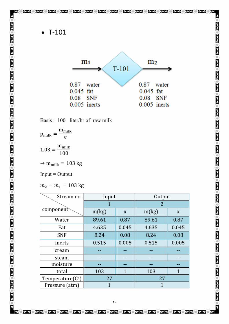
T-101
Basis : 100 liter/hr of raw milk
p���� =m����
v
1.03 =m����
100
→ m���� = 103 kg
Input = Output
�� = �� = 103 kg
Stream no.
component
Input Output
1 2
m(kg) x m(kg) x
Water 89.61 0.87 89.61 0.87
Fat 4.635 0.045 4.635 0.045
SNF 8.24 0.08 8.24 0.08
inerts 0.515 0.005 0.515 0.005
cream -- -- -- --
steam -- -- -- -- moisture -- -- -- --
total 103 1 103 1
Temperature(Co) 27 27 Pressure (atm) 1 1

٢١
F-101
Inerts m.b
Input = Output
0.005 103 = 1 ��
→ �� = 0.515 �����
Total m.b
Input = Output
�� = �� + ��
103 = 0.515 + ��
→ �� = 102.485 �����
water m.b
Input = Output
0.87 103 = ������ 102.485

٢٢
������ = 0.8744
Fat m.b
Input = Output
0.045 103 = ���� 102.485
���� = 0.04523
SNFm.b
Input = Output
0.08 103 = ���� 102.485
���� = 0.0804
������ ���= 0.8744 102.485 = 89.6129 ��
�������= 0.04523 102.485 = 4.6354 ��
���� ���= 0.0804 102.485 = 8.2398 ��
Stream no.
component
Input Output
2 3 4
m(kg) x m(kg) x m(kg) x
Water 89.61 0.87 -- -- 89.6129 0.8744
Fat 4.635 0.045 -- -- 4.6354 0.04523
SNF 8.24 0.08 -- -- 8.2398 0.0804
Inerts 0.515 0.005 0.515 1 -- --
Cream -- -- -- -- -- --
Steam -- -- -- -- -- -- moisture -- -- -- -- --
Total 103 1 0.515 1 102.485 1 Temperature(Co) 27 27 27
Pressure (atm) 1 1 1

٢٣
HE-101
Inerts m.b
Input = Output
�� = ��
→ �� = 102.485 �����
Stream no.
Component
Input Output
4 5
m(kg) x m(kg) x
Water 89.6129 0.8744 89.6129 0.8744
Fat 4.6354 0.04523 4.6354 0.04523
SNF 8.2398 0.0804 8.2398 0.0804
Inerts -- -- -- --
Cream -- -- -- --
Steam -- -- -- -- Moisture -- -- -- --
Total 102.485 1 102.485 1 Temperature(Co) 27 80
Pressure (atm) 1 1

٢٤
C-101
-In this process we remove cream from milk and it yields 15% milk of the
total input, so :
�����=������(��)
�����(��)
0.15 =��
102.485
→ �� = 15.3728 ��
Total m.b
Input = Output
�� = �� + ��
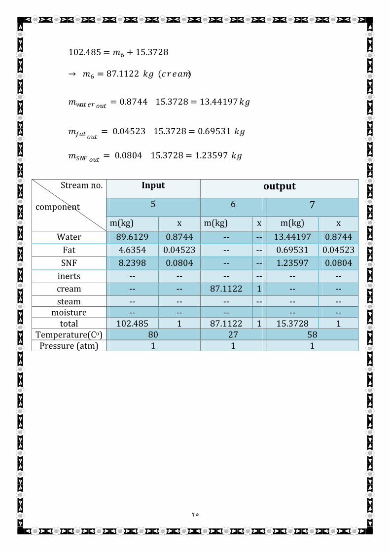
٢٥
102.485 = �� + 15.3728
→ �� = 87.1122 �� (�����)
������ ���= 0.8744 15.3728 = 13.44197 ��
�������= 0.04523 15.3728 = 0.69531 ��
���� ���= 0.0804 15.3728 = 1.23597 ��
Stream no.
component
Input output
5 6 7
m(kg) x m(kg) x m(kg) x
Water 89.6129 0.8744 -- -- 13.44197 0.8744
Fat 4.6354 0.04523 -- -- 0.69531 0.04523
SNF 8.2398 0.0804 -- -- 1.23597 0.0804
inerts -- -- -- -- -- --
cream -- -- 87.1122 1 -- --
steam -- -- -- -- -- -- moisture -- -- -- -- --
total 102.485 1 87.1122 1 15.3728 1 Temperature(Co) 80 27 58
Pressure (atm) 1 1 1
٢٦
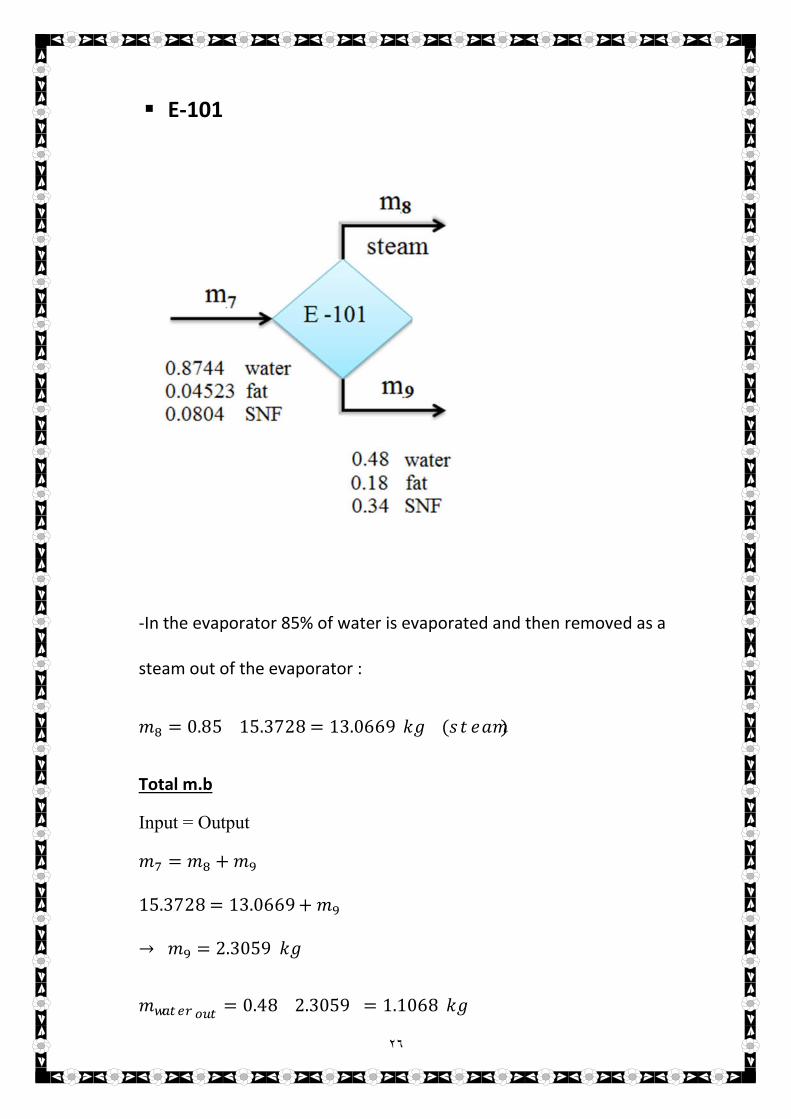
E-101
-In the evaporator 85% of water is evaporated and then removed as a
steam out of the evaporator :
�� = 0.85 15.3728 = 13.0669 �� (�����)
Total m.b
Input = Output
�� = �� + ��
15.3728 = 13.0669 + ��
→ �� = 2.3059 ��
������ ���= 0.48 2.3059 = 1.1068 ��

٢٧
�������= 0.18 2.3059 = 0.4151 ��
���� ���= 0.34 2.3059 = 0.7840 ��
Stream no.
component
Input Output
7 8 9
m(kg) x m(kg) x m(kg) x
Water m(kg) x -- -- 1.1068 0.48
Fat 13.44197 0.8744 -- -- 0.4151 0.18
SNF 0.69531 0.04523 -- -- 0.7840 0.34
inerts 1.23597 0.0804 -- -- -- --
cream -- -- -- -- -- --
steam -- -- 13.0669 1 -- --
moisture -- -- -- -- -- total 15.3728 13.0669 1 2.3059 1
Temperature(Co) 58 71 71 Pressure (atm) 1 1 1
٢٨
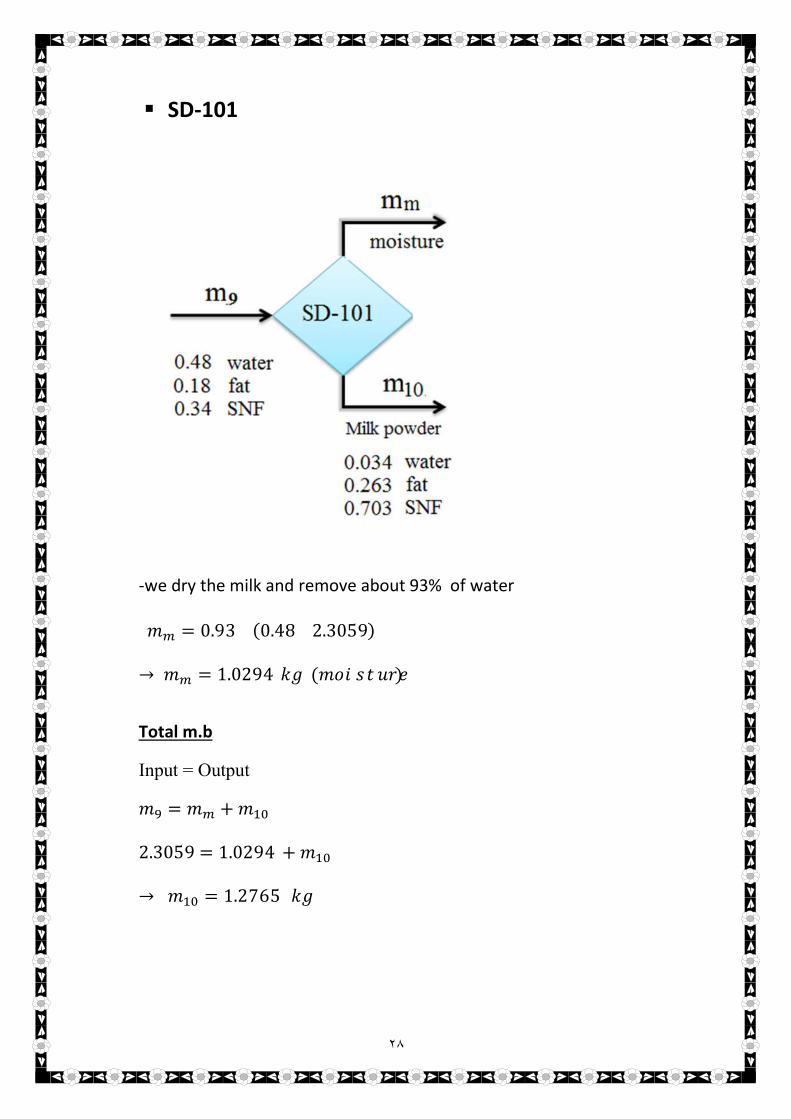
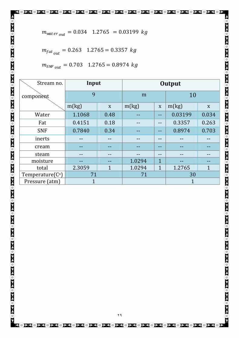
SD-101
-we dry the milk and remove about 93% of water
�� = 0.93 (0.48 2.3059)
→ �� = 1.0294 �� (��������)
Total m.b
Input = Output
�� = �� + ���
2.3059 = 1.0294 + ���
→ ��� = 1.2765 ��
٢٩
������ ���= 0.034 1.2765 = 0.03199 ��
�������= 0.263 1.2765 = 0.3357 ��
���� ���= 0.703 1.2765 = 0.8974 ��
Stream no.
component
Input Output
9 m 10
m(kg) x m(kg) x m(kg) x
Water 1.1068 0.48 -- -- 0.03199 0.034
Fat 0.4151 0.18 -- -- 0.3357 0.263
SNF 0.7840 0.34 -- -- 0.8974 0.703
inerts -- -- -- -- -- --
cream -- -- -- -- -- --
steam -- -- -- -- -- -- moisture -- -- 1.0294 1 -- --
total 2.3059 1 1.0294 1 1.2765 1 Temperature(Co) 71 71 30
Pressure (atm) 1 1

٣٠
Energy
Balance

٣١
The calculations will be based on the first law of thermodynamic
( the total quantity of energy is constant. When energy disappear in
one form, it appears in other form).
[(H + (1 2⁄ U�)+ Z g)m] = Q W�
Where;
Q = heat gained by system (positive)
W� = work done by system
The Assumptions :
1- Neglect kinetic and potential energy
H = Q W�
2- For open system shaft work
W� = 0
3- For open system with physical operation
H = Q
4- For open system with chemical reaction :
H + H�������� = Q
H = H�� H���
H = m Cp���� T
Cp���� = Σ(x� Cp�) Or;
Cp���� = Σ(y� Cp�)
T = T T���������
T��������� = 298 K

٣٢
HE-101
H = Q
H = H�� H���
H = H� H�
H� = m� Cp���� T
H� = m� Cp���� (T T���������)
= 102.485 0.920 (300 298)
= 188.5724 kj/hr
H� = m� Cp���� (T T���������)
= 102.485 0.918 (353 298)
= 5,174.4677 kj/hr
H = H� H�
= 188.5724 5,174.4677
= 4,985.8953 kj/hr
Q = 4,985.8953 kj/hr
Q = m H
Q = m����� (�� ��)
The steam enters at 110 oC & H= 3452 kj/hr and the steam out at 101
oC & H= 2088 kj/hr.
4,985.8953 = m����� (3452 2088 )
m����� = 3.6554 �����

٣٣
E-101
H = Q
H = H�� H���
H = H� (H� + H�)
H� = m� Cp���� T
H� = m� Cp���� (T T���������)
= 15.3728 0.938 (331 298)
= 475.8496 kj/hr
���� ����� ������, H� = 4,205.6802 kj/hr
H� = m� Cp���� (T T���������)
= 2.3059 0.930 (344 298)
= 98.6464 kj/hr
H = H� (H� + H�)
= 475.8496 (4,205.6802 + 98.6464)
= 3,828.477 kj/hr
Q = 3,828.477 kj/hr

٣٤
SD-101
H = Q
H = H�� H���
H = (H� + H�) H�
H� = m� Cp���� (T T���������)
= 2.3059 0.930 (344 298)
= 98.6464 kj/hr
H� = m��� Cp��� (T T���������)
= 10.1563 0.990 (473 298)
= 1,759.5798 kj/hr
H� = m�� Cp���� (T T���������)
= 1.2765 0.920 (303 298)
= 702.8024 kj/hr
H = (H� + H�) H�
= (98.6464 + 1,759.5798) (702.8024)
= + 1,155.4238 kj/hr
Q = + 1,155.4238 kj/hr

٣٥
Equipment
Design

٣٦
Spray Dryer
Spray dryers are normally used for liquid and dilute slurry feeds, but
can be designed to handle any material that can be pumped. The material
to be dried is atomized in a nozzle, or by a disc type atomizer, positioned
at the top of a vertical cylindrical vessel. Hot air flows up the vessel (in
some designs downward) and conveys and dries the droplets. The liquid
vaporizes rapidly from the droplet surface and open, porous particles are
formed. The dried particles are removed in a cyclone separator or bag
filter.
The main advantages of spray drying are the short contact time,
making it suitable for drying heat-sensitive materials, and good control of
the product particle size, bulk density, and form. Because the solids
concentration in the feed is low, the heating requirements will be high.

٣٧

٣٨
Process Design and Safety Considerations
Dryers that remove water from solids usually use ambient air as the
drying gas. The air can be heated in the dryer or preheated by indirect
heat transfer from steam tubes at the dryer inlet. When high inlet
temperatures are needed, direct heat transfer can be used by firing a
burner in the inlet air. Such burners are typically fueled with natural gas
or a process waste stream. The increase in inlet humidity due to the water
vapor formed during combustion is not problematic if the inlet
temperature is high.
For thermally-sensitive products that must be dried with a low gas
inlet temperature, the inlet air is sometimes preconditioned by passing it
over a bed of molecular sieve adsorbent to ensure constant low inlet
humidity. The adsorbent can then be regenerated in a temperature-swing
cycle. Chilling the inlet air to remove moisture by condensation is also
possible, but is generally avoided as chilling increases the heat load on
the heater of the dryer.
The air or flue-gas flow exiting a once-through air-water dryer is
usually ducted away from the dryer and discharged away from the plant.
The exiting air will be hot, moist, and may contain particulate material if
the solids are prone to dust formation. Gas-cleaning systems will be

٣٩
specified if the dust load is high or if there are environmental or safety
concerns with respect to the dust; The gas-cleaning equipment is usually
located close to the dryer to prevent deposition of the dust or
condensation in the ducting.
When a flammable solvent is removed from a solid, or when a
combustible dust could be formed, air should not be used as the drying
gas. Although it is possible to design the dryer to operate outside the
flammability envelope, there is nevertheless a risk that flammable
conditions may occur during a process upset, with the potential to cause a
fire or explosion. Instead, a closed-loop, recirculating gas system using an
inert gas such as nitrogen can be used, as shown in Figure below
٤٠
In a closed-loop system, the gas leaving the dryer is sent to cyclones,
filters, or other gas-cleaning equipment to remove dust. The cleaned gas
is cooled to allow the solvent to be condensed and recovered. The gas is
then compressed by a fan or blower and returned to the heater at the dryer
inlet. The dryer in a closed-loop system is designed to be gas tight and a
small amount of make-up gas may be added to allow for the gas that
flows out in the void spaces of the solid product.
Recirculating gas dryers are also used when the solid has the
potential to form a toxic or corrosive dust that would be harmful if
discharged to the atmosphere. Note that not all dryers are suitable for
operation in recirculating-gas mode. The dryer design must enable
airtight operation
٤١
Design Of A Spray Dryer
Spray-drying technology is used in a wide variety of processes
ranging from manufacture of food products to pharmaceuticals. Most
recently, spray-drying technology has been investigated to produce
hollow micro-particles .This chapter presents an approach to design a
spray-drying chamber using a rate-based description of the drying process
combined with a droplet size distribution model. The primary spray-
drying chamber design criterion is the moisture content of the final
particle. The prediction of the final particle properties are compared to
experimental data obtained from a laboratory spray-drying unit. The
results show that the final spray-drying chamber design is sensitive to the
liquid feed flow rate, the inlet drying gas temperature, and heat loss.
Background
Spray-drying technology is used extensively in many industries such
as the food industry; for example, to dry a feed solution in order to
generate particular products from the solution . Spray-drying technology
also has been used to manufacture hollow or solid micro-particles for
different applications (e.g., light weight composites). Hollow spherical
particles have a number of potential applications, but one of the most

٤٢
important application is their use as fillers in syntactic foams. Hollow
particles provide a means to produce light composite materials (foams)
with desirable mechanical, thermal, and electrical properties that can be
easily molded and machined due to the small size of the particles.
The properties of the hollow particles affect the properties of the
syntactic foams – most notably, the density of the particles and their
mechanical properties. Both of these properties depend mainly on three
factors :
• The type of raw material used.
• The diameter of the particles.
• The thickness of the skin.
In a spray-drying operation, there are three main phenomena:
1. Atomization of the liquid feed
2. Drying of the droplets once they are formed
3. Motion of the droplet in the spray-drying unit.
The design of spray dryers has remained mainly empirical for several
reasons, but primary among these is a fundamental understanding of the
atomization process. In general, experimental correlations are relied upon
to describe the atomized spray The models used to describe the spray
drying process may contain material and energy balances between the
two phases – the droplet phase and the bulk gas phase; or material and

٤٣
energy balances between these two phases and a description of the
equilibrium between the dispersed and continuous phases; or rate-based
descriptions, which do not assume the existence of an equilibrium.
Experimental system
The spray drying system consists of the following:
• A spray drying chamber has a cylinder-on-cone geometry. The atomizer
feed to the top of the vessel and the heating gas feeds to the side wall near
the top. Thermocouples are set along the wall of the vessel to measure the
temperature of the heating gas. The conical section has an opening at the
bottom to remove the spent gas and particles. A cyclone is used to
separate the gas from the particles.
• The atomizer is used to introduce the liquid feed to the spray drying
chamber. The atomizer used in this work can be set to produces 10-100
micron sized droplets.
• Heaters are provided to heat the heating gas before it enters the spray
drying chamber. The heaters are used to generate temperatures as high as
1000 oF.
• A peristaltic pump is used to meter the feed solution to the atomizer.
• A cyclone is used which separates the product from the spent heating
gas.
A schematic of the spray drying system is shown in Figure below

٤٤
Figure above shows samples of the hollow micro-particles produced by
the experimental system. These hollow micro-particles are spherical in
shape with impermeable skins. The mean particle diameters are between
10 to 80 microns with shell thickness of 2 to 10 microns.
٤٥
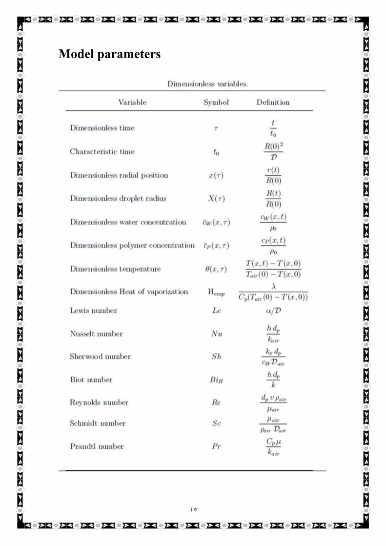
Model parameters
٤٦
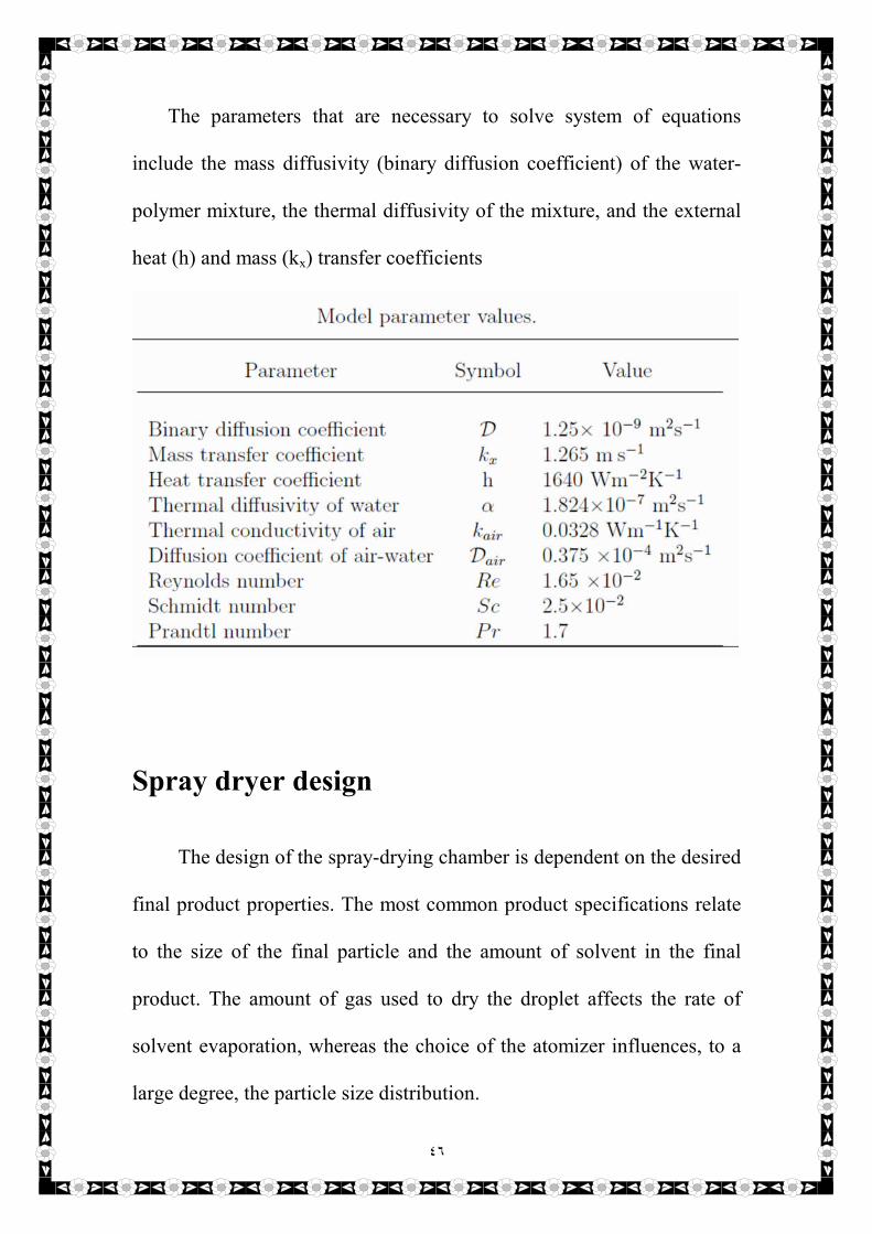
The parameters that are necessary to solve system of equations
include the mass diffusivity (binary diffusion coefficient) of the water-
polymer mixture, the thermal diffusivity of the mixture, and the external
heat (h) and mass (kx) transfer coefficients
Spray dryer design
The design of the spray-drying chamber is dependent on the desired
final product properties. The most common product specifications relate
to the size of the final particle and the amount of solvent in the final
product. The amount of gas used to dry the droplet affects the rate of
solvent evaporation, whereas the choice of the atomizer influences, to a
large degree, the particle size distribution.

٤٧
The following design approach is adapted from the work of Gauvin
and Katta [18]. Given the feed and product specifications, the size of the
spray-drying chamber, the heating requirements, and the flow rate of the
drying gas can be determined iteratively. The design calculations are
performed in three steps:
• Step one – involves calculation of the liquid droplet trajectories;
• Step two – determines the drying gas flow pattern; and
• Step three uses the results of the previous steps to obtain the heat- and
mass-transfer rates between the liquid droplet and the gas, the heating
requirements, and the size of the spray-drying chamber.
The size of the spray chamber is determined by the trajectory of the
largest droplet. The design criterion is that the largest droplet must
contain less than 10% moisture before the droplet contacts the spray
chamber wall. Knowing the distance (both radial and axial) travelled by
the droplet before the 10% moisture limit is reached provides the radius
and length of the spray-drying chamber.
The droplet’s trajectories are determined using a Lagrangian
formulation. It has been shown that the Eulerian formulation results in
numerical errors when tracking particulates. Additionally, the
computational burden is reduced in the Lagrangian formulation because
٤٨
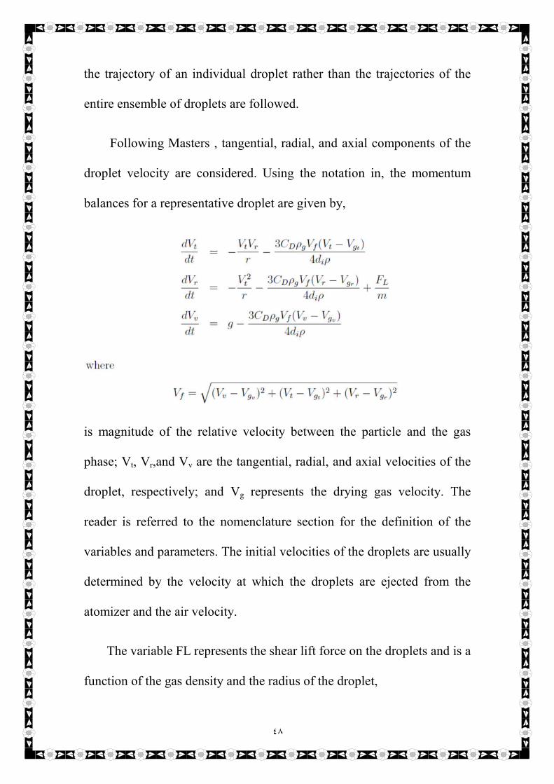
the trajectory of an individual droplet rather than the trajectories of the
entire ensemble of droplets are followed.
Following Masters , tangential, radial, and axial components of the
droplet velocity are considered. Using the notation in, the momentum
balances for a representative droplet are given by,
is magnitude of the relative velocity between the particle and the gas
phase; Vt, Vr,and Vv are the tangential, radial, and axial velocities of the
droplet, respectively; and Vg represents the drying gas velocity. The
reader is referred to the nomenclature section for the definition of the
variables and parameters. The initial velocities of the droplets are usually
determined by the velocity at which the droplets are ejected from the
atomizer and the air velocity.
The variable FL represents the shear lift force on the droplets and is a
function of the gas density and the radius of the droplet,

٤٩
The shear lift force is transverse to the direction of flow and thus acts in
the radial direction .
The liquid spray, as it travels down the spray-drying chamber can be
classified into two zones, the nozzle zone and the entrainment zone. In
the nozzle zone, the spray’s velocity remains influenced by the atomizer
while in the entrainment zone, the spray’s velocity is influenced by the
drying gas. In this work, it is assumed that the atomizer creates sprays
with very low velocities. Thus, only changes to the spray’s velocity in the
entrainment zone are assumed non negligible.
At any vertical distance from the liquid spray’s entrance, for a
tangentially introduced gas in a chamber with a circular cross-section, the
radial variation in the tangential velocity of the gas stream is given by,
where the radius of the chamber (Rx) is a function of the axial distance, x,
as measured from the entry point of the liquid feed.
The radial variation in the axial velocity of the gas stream is given by,

٥٠
The coefficients, C1 and C2, in Equations are found experimentally. The
above relations were obtained in a system very similar in geometry and
gas flow pattern to the one under consideration.
To model the heat– and mass– transfer between the droplet phase and
the air phase, the following assumptions are made:
1. The solution is well-mixed and all droplets contain the same amount of
solvent and solute.
2. The droplets are exposed to the same amount of heat.
3. The heat lost from the unit to the surroundings is 20%.
The heat (q) supplied to the droplets and the amount of solvent lost by
the droplets due only to the mass-transfer between the droplets and the
gas are given by,
where ni is the number of droplets, kg is the thermal conductivity of the
gas, Dv is the solvent-gas binary diffusion coefficient, cS is the solvent
concentration at the surface of the droplet, and c is solvent concentration
in the gas surrounding the droplet.
The Nusselt number, Nu, represents the ratio of heat transferred due
to convection and conduction .The Sherwood number, Sh, represents the

٥١
ratio of mass transferred by convection and diffusion [64]. Both the
Nusselt and Sherwood numbers can be determined from the Reynolds
number, Re, which is a ratio between the inertial and viscous forces. The
following equations are used to calculate the Nu and Sh numbers,
The Schmidt number, Sc, is a ratio between kinematic and diffusive
viscosities and the Prandtl number, Pr, represents a ratio between
momentum diffusivity and thermal diffusivity. It is found that the
contribution to the Nusselt and Sherwood numbers from the Reynolds
and Prandtl numbers is negligible, hence both Nu and Sh are
approximately equal to two. This finding implies that the main
mechanisms of mass and heat transport in the reactor are diffusion and
conduction, respectively.
The amount of gas, Wg, required to dry the droplet is found by taking
an overall energy balance over the spray dryer,
where q` is the heat loss, which is assumed to be 20% of the total heat
supplied. The evaporation rate, Ex up to an axial distance x, is estimate as
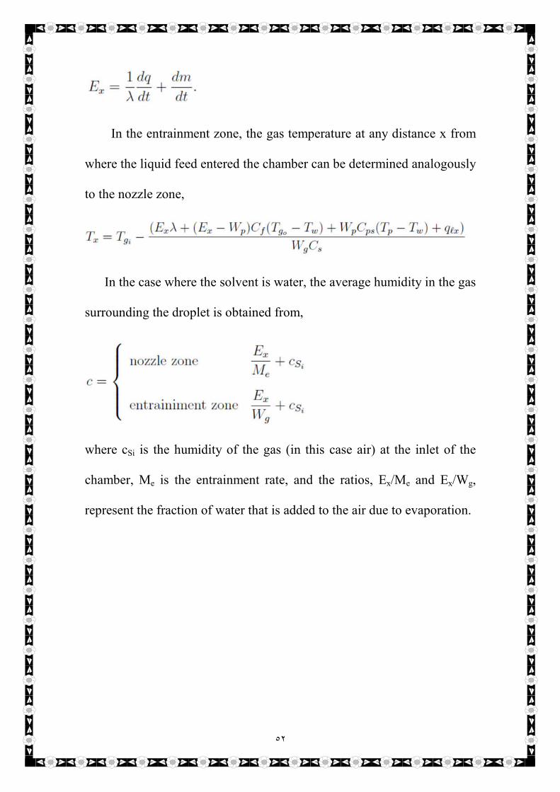
٥٢
In the entrainment zone, the gas temperature at any distance x from
where the liquid feed entered the chamber can be determined analogously
to the nozzle zone,
In the case where the solvent is water, the average humidity in the gas
surrounding the droplet is obtained from,
where cSi is the humidity of the gas (in this case air) at the inlet of the
chamber, Me is the entrainment rate, and the ratios, Ex/Me and Ex/Wg,
represent the fraction of water that is added to the air due to evaporation.

٥٣
Design steps
In the design of the spray dryer, the important design parameters are
the chamber dimensions, the heating gas flow rate and the residence time
of the particles in the spray dryer.
The design equations for the spray-drying chamber are given by
Equations explained above . The approach to obtain the design
parameters for the spray dryer can be summarized as follows:
1. Choose a design criterion.
The criterion selected is that the largest particle contains _ 10% water. To
compare to existing laboratory data, a binary liquid mixture of polymer
and water with air as the drying gas is selected.
2. Choose the atomizer type and spray-drying chamber geometry.
An atomizer and a chamber geometry of a cylindrical top and conical
bottom are selected to provide a comparison to the results obtained from a
similar laboratory scale unit. The choice of the atomizer fixes the droplet
size distribution.
3. Track the largest droplet as it passes through the chamber by solving
the resulting spray-dryer design and droplet equations simultaneously.
The position of the largest particle reaches less than 10% moisture gives
the dimensions of the spray chamber. The axial distance of the particle

٥٤
from the atomizer at this point gives the length while the radial distance
gives the radius of the spray drying chamber.
4. The residence time of the particles is also obtained from the velocity
equations.
The numerical solver must be able to account for the moving
boundary of the particle to obtain accurate estimates of the chamber size,
the gas flow rate and the heating requirements. The process of obtaining
the design parameters is an iterative process.
Spray dryer model results
The mass-based droplet distribution is known to be log-normal [68].
Using this distribution, six droplet sizes, listed in Table below, are
selected. The assumed nominal operating conditions are given in Table
below. A numerical solution of the droplet and spray-dryer design models
gives the design parameters listed in Table after it, for the nominal
operating conditions.

٥٥

٥٦
Cost
Estimation

٥٧
COST ESTIMATION
Fixed capital investment for cost index (2013 ) = 567.3
Cost index for ( 2017) = 567.5
Therefore present fixed capital investment
Present cost = original cost ( index value at present time/ index
value at time original cost was obtained)
=14,000,000 $ * (567.5/567.3)= 14,004,935 $
Estimation of total investment cost:
1- Direct cost:
a- Purchased equipment cost:
(15 - 40% of FCI ) Assume 35 % of FCI
= 14,004,935 * 0.35 = 4,901,727.25 $
b- Installation cost:
(35 - 45% of PEC) Assume 40 % ,where PEC , Purchased
equipment cost
= 4,901,727.25 * 0.40 = 1,960,690.9 $
c- Instrument and control installed:(6 -30% of PEC) Assume 25
% of PEC
= 4,901,727.25 * 0.25 = 1,225,431.82 $
٥٨
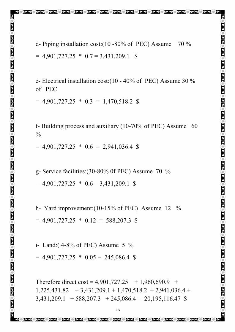
d- Piping installation cost:(10 -80% of PEC) Assume 70 %
= 4,901,727.25 * 0.7 = 3,431,209.1 $
e- Electrical installation cost:(10 - 40% of PEC) Assume 30 %
of PEC
= 4,901,727.25 * 0.3 = 1,470,518.2 $
f- Building process and auxiliary (10-70% of PEC) Assume 60
%
= 4,901,727.25 * 0.6 = 2,941,036.4 $
g- Service facilities:(30-80% 0f PEC) Assume 70 %
= 4,901,727.25 * 0.6 = 3,431,209.1 $
h- Yard improvement:(10-15% of PEC) Assume 12 %
= 4,901,727.25 * 0.12 = 588,207.3 $
i- Land:( 4-8% of PEC) Assume 5 %
= 4,901,727.25 * 0.05 = 245,086.4 $
Therefore direct cost = 4,901,727.25 + 1,960,690.9 +
1,225,431.82 + 3,431,209.1 + 1,470,518.2 + 2,941,036.4 +
3,431,209.1 + 588,207.3 + 245,086.4 = 20,195,116.47 $
٥٩
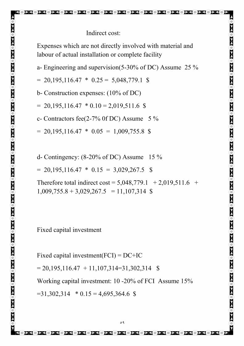
Indirect cost:
Expenses which are not directly involved with material and
labour of actual installation or complete facility
a- Engineering and supervision(5-30% of DC) Assume 25 %
= 20,195,116.47 * 0.25 = 5,048,779.1 $
b- Construction expenses: (10% of DC)
= 20,195,116.47 * 0.10 = 2,019,511.6 $
c- Contractors fee(2-7% 0f DC) Assume 5 %
= 20,195,116.47 * 0.05 = 1,009,755.8 $
d- Contingency: (8-20% of DC) Assume 15 %
= 20,195,116.47 * 0.15 = 3,029,267.5 $
Therefore total indirect cost = 5,048,779.1 + 2,019,511.6 +
1,009,755.8 + 3,029,267.5 = 11,107,314 $
Fixed capital investment
Fixed capital investment(FCI) = DC+IC
= 20,195,116.47 + 11,107,314=31,302,314 $
Working capital investment: 10 -20% of FCI Assume 15%
=31,302,314 * 0.15 = 4,695,364.6 $

٦٠
2- Total capital investment
Estimation of total product cost(TPC):
Fixed charges:
a- Depreciation: (10% of FCI for machinery)
= 31,302,314 * 0.1 = 3,130,231.4 $
b-Local taxes: (3-4% of TPC= FCI) Assume 3 %
= 31,302,314 * 0.03 = 939,069.42 $
c- Insurances(0.4-1% of FCI) Assume 0.7 %
= 31,302,314 * 0.007 = 219,116.198 $
d-Rent: (8-12% of FCI) Assume 10 %
= 31,302,314 * 0.1 = 3,130,231.4 $
Therefore total fixed charges = 3,130,231.4 + 939,069.42 +
219,116.198 + 3,130,231.4 = 7,418,648.418 $
But, Fixed charges = (10-20% of TPC) Assume 20%
Therefore Total product cost = total fixed charges / 0.2 or *
100/2
= 7,418,648.418 / 0.2 = 37,093,242.09 $

٦١
Direct production:
a- Raw material: (10-50% 0f TPC) Assume 45 %
= 37,093,242.09 * 0.45 = 16,691,958.9405 $
b- Operating labor(OL): (10-20% of TPC) Assume 20 %
= 37,093,242.09 * 0.2 = 7,418,648.418 $
c- Direct supervisory and electric labor (10-25% of OL)
Assume 25 %
= 37,093,242.09 * 0.25 = 9,273,310.5225 $
d- Utilities (10-20% of TPC) Assume 15 %
= 37,093,242.09 * 0.15 = 5,563,986.3135 $
e- Maintenance (2-10% of FCI) Assume 8 %
= 37,093,242.09 * 0.08 = 2,967,459.3672 $
f- Operating supplies (OS): (10-20% of maintenance)
Assume 20 %
= 37,093,242.09 * 0.2 = 7,418,648.418 $
g- Laboratory charges (10-20% of OL) Assume 20 %
= 37,093,242.09 * 0.2 = 7,418,648.418 $
h- Patent and royalties (2-6% of TPC) Assume 5 %
= 37,093,242.09 * 0.05 = 1,854,662.1045 $
Plant overhead cost: 50-70% of (OL+OS+M) Assume 75 %
= ( 7,418,648.418 + 7,418,648.418 + 2,967,459.3672 ) * 0.75
= 13,353,567.1524 $
٦٢
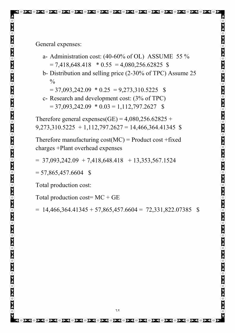
General expenses:
a- Administration cost: (40-60% of OL) ASSUME 55 %
= 7,418,648.418 * 0.55 = 4,080,256.62825 $
b- Distribution and selling price (2-30% of TPC) Assume 25
%
= 37,093,242.09 * 0.25 = 9,273,310.5225 $
c- Research and development cost: (3% of TPC)
= 37,093,242.09 * 0.03 = 1,112,797.2627 $
Therefore general expenses(GE) = 4,080,256.62825 +
9,273,310.5225 + 1,112,797.2627 = 14,466,364.41345 $
Therefore manufacturing cost(MC) = Product cost +fixed
charges +Plant overhead expenses
= 37,093,242.09 + 7,418,648.418 + 13,353,567.1524
= 57,865,457.6604 $
Total production cost:
Total production cost= MC + GE
= 14,466,364.41345 + 57,865,457.6604 = 72,331,822.07385 $
٦٣
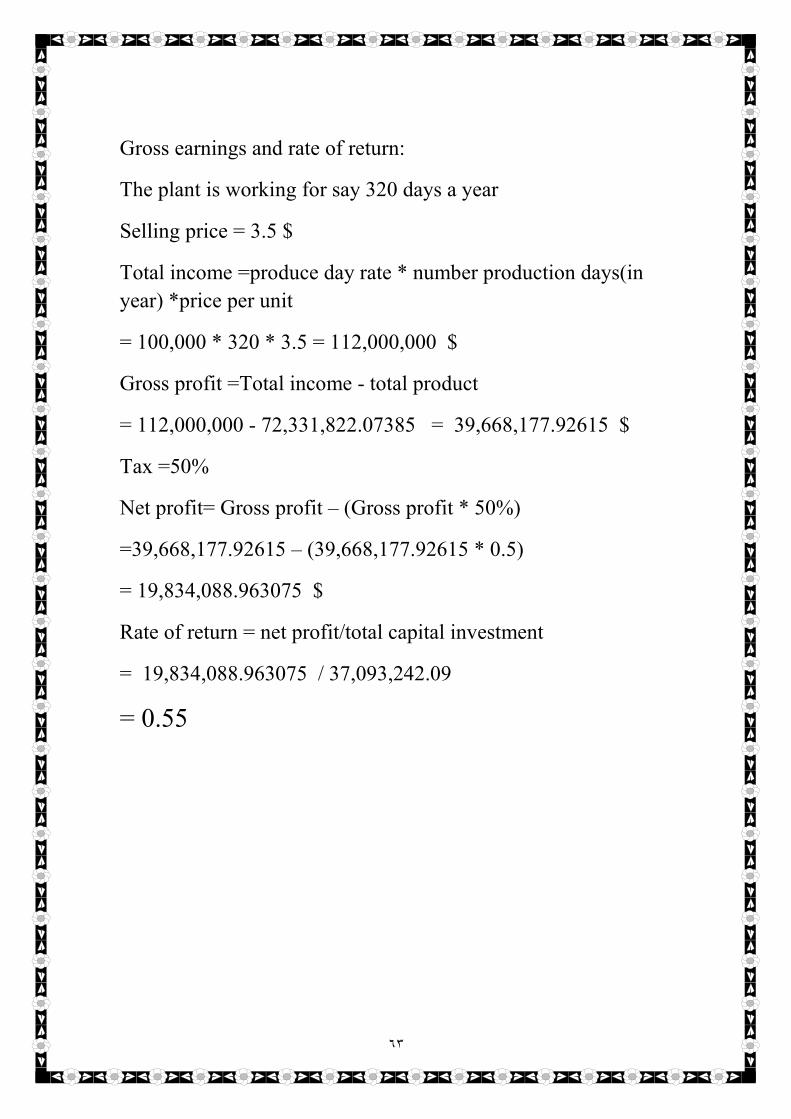
Gross earnings and rate of return:
The plant is working for say 320 days a year
Selling price = 3.5 $
Total income =produce day rate * number production days(in
year) *price per unit
= 100,000 * 320 * 3.5 = 112,000,000 $
Gross profit =Total income - total product
= 112,000,000 - 72,331,822.07385 = 39,668,177.92615 $
Tax =50%
Net profit= Gross profit – (Gross profit * 50%)
=39,668,177.92615 – (39,668,177.92615 * 0.5)
= 19,834,088.963075 $
Rate of return = net profit/total capital investment
= 19,834,088.963075 / 37,093,242.09
= 0.55

٦٤
References
1. Wikipedia ; The free encyclopedia .
2. shreve's chemical process industries 5th edition ,New York (1975).
3. J.M. Coulson and J. F. Richardson , Chemical Engineering
Design, vol.6 ,2nd Edition ; chapter 19, page 1047-1094.
4. J.M. Coulson and J. F. Richardson , Chemical Engineering
Design, vol.6 ,2nd Edition ; chapter 6, page 243-278.
5. Robert H. Perry and Don Green , Chemical Engineering Hand
Book , 6th Edition M (G raw-Hill New York) (1984). (we use this
book as a reference for the specific heats and densities for some
substances).
6. Graduation project/ university of technology faculty of engineering
/ chemical engineering department for he academic year 2005.
7. Levenspiel Octave ,''Chemical Reaction Engineering 2ndEd.,
Wiley Eastern Ltd .,1991.
8. www.viscopedia.com/viscosity-tables/substanes/water.
9. http://en.m.wikipedia.org/wiki/thermal_conductivity.
10. Antonie.frostburg.edu/chem/sence/javascript/water-density.html.
11. Kerk-othmer encyclopedia of chemical technology (4th edition).
12. Hesse, herman C. and Rushton, J. Henry " process equipment
design", 4th edition, new delhi.