MIL-STD-704F Aircraft Electric Power Characteristics Test ... · MIL-STD-704F OPTION PACIFIC POWER...
129
MIL-STD-704F OPTION MIL-STD-704F OPTION MIL-STD-704F Aircraft Electric Power Characteristics Test Sequences OPERATION MANUAL Pacific Power Source, Inc. Part Number: 149153 Version: 1.1 Document number: 149153-10 September 07, 2013
Transcript of MIL-STD-704F Aircraft Electric Power Characteristics Test ... · MIL-STD-704F OPTION PACIFIC POWER...
MIL-STD-704F OPTION
MIL-STD-704F OPTION
MIL-STD-704F Aircraft Electric Power Characteristics Test Sequences
OPERATION MANUAL
Pacific Power Source, Inc.
Part Number: 149153
Version: 1.1
Document number: 149153-10
September 07, 2013
MIL-STD-704F OPTION
PACIFIC POWER SOURCE, INC Page 2 of 129
THIS PAGE INTENTIONALLY LEFT BLANK

MIL-STD-704F OPTION
PACIFIC POWER SOURCE, INC Page 3 of 129
SUPPLEMENTAL END USER LICENSE AGREEMENT FOR PACIFIC POWER SOURCE, INC. ADD-ON SOFTWARE
IMPORTANT – PLEASE READ CAREFULLY: This Pacific Power Source, Inc. (“Pacific Power Source”) Supplemental End-User License Agreement ("Supplemental EULA") is a legal agreement between You (either an individual person or a single legal entity, who will be referred to in this Supplemental EULA as "You") and Pacific Power Source for the additional Pacific Power Source Software that accompanies this Supplemental EULA, including any associated media, printed materials and electronic documentation (the "Add-on Software"). This Add-on Software also includes any software updates, further add-on components, web services and/or supplements that Pacific Power Source may provide to You or make available to You after the date You obtain Your initial copy of the Add-on Software to the extent that such items are not accompanied by a separate license agreement or terms of use. By installing, copying, downloading, accessing or otherwise using the Add-on Software, You expressly and unequivocally agree to be bound by the terms and conditions of the original EULA under which you have licensed the underlying Pacific Power Source Software as well as this Supplemental EULA. However, if you do not have a valid EULA for the underlying Pacific Power Source Software, You are not authorized to install, copy, or otherwise use the Add-on Software and You have no rights under this Supplemental EULA. To the extent that any terms in this Supplemental EULA conflict with the terms in the applicable Pacific Power Source Software EULA, the terms of this Supplemental EULA control solely with respect to the Add-on Software.
SOFTWARE LICENSE
The Add-on Software is owned by Pacific Power Source and is protected by United States copyright and intellectual property laws and treaties. Therefore You must treat the Add-on Software like any other copyrighted material. The Add-on Software is licensed, not sold. All instructions, methods, techniques and algorithms provided with the Add-on Software, including, but not limited to, Test Sequences, Test Steps, and Output Sequences, remain the sole property of Pacific Power Source, Inc.
1. GRANT OF LICENSE. This Section of the Supplemental EULA describes Your general rights to install and use the Add-on Software The license rights described in this Section are subject to all other terms and conditions of this Supplemental EULA. All rights not expressly granted are reserved by Pacific Power Source.
General License Grant to Install and Use Software. You may install and use one copy of the Add-on Software on a single computer, device, workstation, terminal, or other digital electronic or analog device ("Device"). If You have a multi-user license for the Add-on Software, then at any time You may have as many copies of the Add-on Software in use as are permitted by the multi-user license. A license for the Add-on Software may not be shared. If the number of users of the Add-on Software exceeds the number of users permitted by applicable license(s), You will be considered in material breach of this agreement. You may, however, either (a) make one copy of the Add-on Software solely for backup or archival purposes, or (b) transfer the Add-on Software to a single hard disk, provided You keep the original solely for backup or archival purposes. You may not copy the written materials accompanying the Add-on Software.
Additional License Grant for Other Media. The Add-on Software may include certain trademarks, photographs, art, graphics, sounds, music and/or video clips (together "Other Media"). If so, the following terms describe Your rights to the Other Media:
a. You do not own any rights in the Other Media and the limited license herein shall be applicable to the Other Media. You may not sell, license or distribute copies of the Other Media on a stand-alone basis or as part of any collection, product or service.
b. You may not use or distribute any of the Other Media that include representations of identifiable individuals, governments, logos, initials, emblems, or trademarks for any commercial purposes or to express or imply any endorsement or association with any product, service, entity, or activity.
MIL-STD-704F OPTION
PACIFIC POWER SOURCE, INC Page 4 of 129
c. You must indemnify, hold harmless, and defend Pacific Power Source from and against any claims or lawsuits, including expert and attorneys' fees that arise from or result from the unauthorized use or distribution of the Other Media by You.
2. DESCRIPTION OF OTHER RIGHTS AND LIMITATIONS.
No Reverse Engineering, Decompilation, and Disassembly. You may not reverse engineer, decompile, or disassemble the Add-on Software, except and only to the extent that such activity is expressly permitted by applicable law notwithstanding this limitation.
Operating System Options. If the Add-on Software is distributed with multiple versions for compatibility with different operating systems, Your license grant extends to using only the applicable version for Your operating system.
Trademarks. This Supplemental EULA does not grant You any rights in connection with any trademarks or service marks of Pacific Power Source.
Support Services. Pacific Power Source may provide You with support services related to the Add-on Software ("Support Services"). Use of Support Services is governed by the Pacific Power Source policies and programs described in other Pacific Power Source-provided materials. Any further supplemental software and/or code provided to You as part of the Support Services are considered part of the Add-on Software and subject to the terms and conditions of this Supplemental EULA. You acknowledge and agree that Pacific Power Source may use technical information You provide to Pacific Power Source as part of the Support Services for its business purposes.
Software Transfer. Except as specified in this Section, the initial licensee of the Add-on Software may make a one-time permanent transfer of this Supplemental EULA and Add-on Software only directly to an end user, provided that the initial licensee has terminated its use of the Add-on Software. This transfer must include all of the Add-on Software (including all component parts, the media and printed materials, any upgrades, this Supplemental EULA, and, if applicable, the Certificate of Authenticity). Such transfer may not be by way of consignment or any other indirect transfer. The transferee of such one-time transfer must agree to comply with the terms of this Supplemental EULA, including the obligation not to further transfer this Supplemental EULA and Add-on Software.
Termination. Without prejudice to any other rights, Pacific Power Source may terminate this Supplemental EULA if You fail to comply with the terms and conditions of this Supplemental EULA. In such event, You agree to destroy all copies of the Add-on Software and all of its component parts.
3. INTELLECTUAL PROPERTY RIGHTS. All title and intellectual property rights in and to the Add-on Software (including but not limited to any images, photographs, animations, video, audio, music, text, and "applets" incorporated into the Add-on Software), the accompanying printed materials, and any copies of the Add-on Software are owned by Pacific Power Source or its suppliers. All title and intellectual property rights in and to the content that is not contained in the Add-on Software, but may be accessed through use of the Add-on Software, is the property of the respective content owners and may be protected by applicable copyright or other intellectual property laws and treaties. This Supplemental EULA grants You no rights to use such content. If this Add-on Software contains documentation that is provided only in electronic form, You may print one copy of such electronic documentation. You may not copy the printed materials accompanying the Add-on Software.
4. BACKUP COPY. After installation of one copy of the Add-on Software pursuant to this Supplemental EULA, You may keep the original media on which the Add-on Software was provided by Pacific Power Source solely for backup or archival purposes. If the original media is required to use the Add-on Software on the Device, You may make one copy of the Add-on Software solely for backup or archival purposes. Except as expressly provided in this
MIL-STD-704F OPTION
PACIFIC POWER SOURCE, INC Page 5 of 129
Supplemental EULA, You may not otherwise make copies of the Add-on Software or the printed materials accompanying the Add-on Software.
5. EXPORT RESTRICTIONS. You acknowledge that the Add-on Software is of U.S. origin. You agree to comply with all applicable international and national laws that apply to the Add-on Software, including the U.S. Export Administration Regulations, as well as end-user, end-use and destination restrictions issued by U.S. and other governments.
6. APPLICABLE LAW.
This Supplemental EULA is governed by the laws of the State of California without regard to conflicts of law principles and in respect of any dispute which may arise hereunder, You hereby consent to the jurisdiction of the federal or state courts sitting in Orange County, California. You also agree to accept service of process by mail, and waive any jurisdictional or venue defenses otherwise available.
7. LIMITED WARRANTY
LIMITED WARRANTY FOR ADD-ON SOFTWARE: Pacific Power Source warrants that the ADD-ON SOFTWARE will perform substantially in accordance with the accompanying materials for a period of ninety (90) days from the date of receipt. This Limited Warranty shall only apply to defects discovered in the ninety (90) day warranty period and as to any defects discovered after the ninety (90) day warranty period, THERE IS NO WARRANTY OF ANY KIND, to the fullest extent permissible by applicable law.
LIMITATION ON REMEDIES; NO CONSEQUENTIAL OR OTHER DAMAGES. Your exclusive remedy for any breach of this Limited Warranty is as set forth below. Except for any refund elected by Pacific Power Source, YOU ARE NOT ENTITLED TO ANY DAMAGES, INCLUDING BUT NOT LIMITED TO CONSEQUENTIAL DAMAGES, if the Add-on Software does not meet Pacific Power Source's Limited Warranty, and, to the maximum extent allowed by applicable law, even if any remedy fails of its essential purpose. The terms of Section 11 below ("Exclusion of Incidental, Consequential and Certain Other Damages") are also incorporated into this Limited Warranty.
EXCLUSIVE REMEDY. Pacific Power Source's entire liability and Your exclusive remedy shall be, at Pacific Power Source's option, (a) return of the price paid (if any) for the Add-on Software, or (b) repair or replacement of the Add-on Software that does not meet this Limited Warranty and that is returned to Pacific Power Source with proof of payment. You will receive the remedy elected by Pacific Power Source without charge, except that You are responsible for any expenses You may incur (e.g. cost of shipping the Add-on Software to Pacific Power Source). This Limited Warranty is void if failure of the Add-on Software has resulted from accident, abuse, misapplication, abnormal use or a virus. Any replacement Add-on Software will be warranted for the remainder of the original warranty period or thirty (30) days, whichever is longer.
8. DISCLAIMER OF WARRANTIES. THE LIMITED WARRANTY THAT APPEARS ABOVE IS THE ONLY EXPRESS WARRANTY MADE TO YOU AND IS PROVIDED IN LIEU OF ANY OTHER EXPRESS WARRANTIES (IF ANY) CREATED BY ANY DOCUMENTATION OR PACKAGING. EXCEPT FOR THE LIMITED WARRANTY AND TO THE MAXIMUM EXTENT PERMITTED BY APPLICABLE LAW, PACIFIC POWER SOURCE PROVIDE THE ADD-ON SOFTWARE AND SUPPORT SERVICES (IF ANY) AS IS AND WITH ALL FAULTS, AND HEREBY DISCLAIM ALL OTHER WARRANTIES AND CONDITIONS, EITHER EXPRESS, IMPLIED OR STATUTORY, INCLUDING, BUT NOT LIMITED TO, ANY (IF ANY) IMPLIED WARRANTIES, DUTIES OR CONDITIONS OF MERCHANTABILITY, OF FITNESS FOR A PARTICULAR PURPOSE, OF ACCURACY OR COMPLETENESS OR RESPONSES, OF RESULTS, OF WORKMANLIKE EFFORT, OF LACK OF VIRUSES AND OF LACK OF NEGLIGENCE, ALL WITH REGARD TO THE ADD-ON SOFTWARE, AND THE PROVISION OF OR FAILURE TO PROVIDE SUPPORT SERVICES. ALSO, THERE IS NO WARRANTY OR CONDITION OF TITLE, QUIET ENJOYMENT, QUIET POSSESSION, OR CORRESPONDENCE TO DESCRIPTION OR NON-INFRINGEMENT WITH REGARD TO THE ADD-ON SOFTWARE. IN ANY JURISDICTION WHICH DOES NOT ALLOW THE EXCLUSION OR LIMITATION OF IMPLIED
MIL-STD-704F OPTION
PACIFIC POWER SOURCE, INC Page 6 of 129
WARRANTIES, ANY IMPLIED WARRANTIES, TO THE EXTENT PERMITTED BY THE APPLICABLE LAWS OF ANY SUCH JURISDICTION, SHALL BE LIMITED TO THE TERM OF THIS AGREEMENT.
PACIFIC POWER SOURCE SPECIFICALLY DISCLAIMS ANY WARRANTY RELATING TO ANY TEST PARAMETERS, RESULTS OR USE OF THE ADD-ON SOFTWARE OR THE DOCUMENTATION IN TERMS OF CORRECTNESS, ACCURACY, RELIABILITY, OR OTHERWISE AND DOES NOT WARRANT THAT THE OPERATION OF THE ADD-ON SOFTWARE WILL BE UNINTERRUPTED OR ERROR FREE.
9. WARNING. PACIFIC POWER SOURCE PRODUCTS ARE NOT DESIGNED WITH COMPONENTS AND TESTING FOR A LEVEL OF RELIABILITY SUITABLE FOR USE IN ANY MEDICAL DIAGNOSIS AND/OR TREATMENT OR AS CRITICAL COMPONENTS IN ANY LIFE SUPPORT SYSTEMS WHERE ANY FAILURE TO PERFORM CAN BE REASONABLY EXPECTED TO CAUSE INJURY OR DEATH.
RELIABILITY OF OPERATION OF THE ADD-ON SOFTWARE CAN BE IMPAIRED BY ADVERSE FACTORS, INCLUDING BUT NOT LIMITED TO FLUCTUATIONS IN ELECTRICAL POWER SUPPLY, COMPUTER HARDWARE MALFUNCTIONS, COMPUTER OPERATING SYSTEM SOFTWARE FITNESS, FITNESS OF COMPILERS AND DEVELOPMENT SOFTWARE USED TO DEVELOP AN APPLICATION, INSTALLATION ERRORS, SOFTWARE AND HARDWARE COMPATIBILITY PROBLEMS, MALFUNCTIONS OR FAILURES OF ELECTRONIC MONITORING OR CONTROL DEVICES, TRANSIENT FAILURES OF ELECTRONIC SYSTEMS (HARDWARE AND/OR SOFTWARE), UNANTICIPATED USES OR MISUSES, OR ERRORS ON THE PART OF THE USER OR APPLICATION DESIGNER. (ADVERSE FACTORS SUCH AS THESE ARE HEREAFTER COLLECTIVELY TERMED “SYSTEM FAILURES.”)
ANY APPLICATION WHERE A SYSTEM FAILURE WOULD CREATE A RISK OF HARM TO PROPERTY OR PERSONS (INCLUDING THE RISK OF BODILY INJURY AND DEATH) SHOULD NOT BE RELIANT SOLELY UPON ELECTRONIC MONITORING DUE TO THE RISK OF SYSTEM FAILURE. TO AVOID DAMAGE, INJURY OR DEATH, THE USER OR APPLICATION DESIGNER MUST TAKE REASONABLY PRUDENT STEPS TO PROTECT AGAINST SYSTEM FAILURES, INCLUDING BUT NOT LIMITED TO BACK-UP OR SHUT DOWN MECHANISMS.
10. EXCLUSION OF INCIDENTAL, CONSEQUENTIAL AND CERTAIN OTHER DAMAGES. TO THE MAXIMUM EXTENT PERMITTED BY APPLICABLE LAW, IN NO EVENT SHALL PACIFIC POWER SOURCE OR ITS SUPPLIERS BE LIABLE FOR ANY SPECIAL, INCIDENTAL, INDIRECT, PUNITIVE OR CONSEQUENTIAL DAMAGES WHATSOEVER (INCLUDING, BUT NOT LIMITED TO, DAMAGES FOR LOSS OF PROFITS, LOST SAVINGS, OR CONFIDENTIAL OR OTHER INFORMATION, FOR BUSINESS INTERRUPTION, LOSS OF BUSINESS INFORMATION, COST OF PROCUREMENT OF SUBSTITUTE TECHNOLOGY, FOR PERSONAL INJURY, FOR LOSS OF PRIVACY, FOR FAILURE TO MEET ANY DUTY INCLUDING OF GOOD FAITH OR OF REASONABLE CARE, FOR NEGLIGENCE, AND FOR ANY OTHER PECUNIARY OR OTHER LOSS WHATSOEVER) ARISING OUT OF OR IN ANY WAY RELATED TO THE USE OF OR INABILITY TO USE THE ADD-ON SOFTWARE, THE PROVISION OF OR FAILURE TO PROVIDE SUPPORT SERVICES, OR OTHERWISE UNDER OR IN CONNECTION WITH ANY PROVISION OF THIS SUPPLEMENTAL EULA, EVEN IN THE EVENT OF THE FAULT, TORT (INCLUDING NEGLIGENCE), STRICT LIABILITY, BREACH OF CONTRACT OR BREACH OF WARRANTY OF PACIFIC POWER SOURCE OR ANY SUPPLIER, AND EVEN IF PACIFIC POWER SOURCE HAS BEEN ADVISED OF THE POSSIBILITY OF SUCH DAMAGES.
11. LIMITATION OF LIABILITY AND REMEDIES. NOTWITHSTANDING ANY DAMAGES THAT YOU MIGHT INCUR FOR ANY REASON WHATSOEVER (INCLUDING, WITHOUT LIMITATION, ALL DAMAGES REFERENCED ABOVE AND ALL DIRECT OR GENERAL DAMAGES), THE ENTIRE LIABILITY OF PACIFIC POWER SOURCE UNDER ANY PROVISION OF THIS SUPPLEMENTAL EULA AND YOUR EXCLUSIVE REMEDY FOR ALL OF THE FOREGOING (EXCEPT FOR ANY REMEDY OF REPAIR OR REPLACEMENT ELECTED BY PACIFIC POWER SOURCE WITH RESPECT TO ANY BREACH OF THE LIMITED WARRANTY) SHAL BE LIMITED TO THE GREATER OF THE AMOUNT ACTUALLY PAID BY YOU FOR THE ADD-ON SOFTWARE. THE FOREGOING LIMITATIONS, EXCLUSIONS AND DISCLAIMERS (INCLUDING SECTIONS 7, 8, AND 9 ABOVE) SHALL APPLY TO THE MAXIMUM EXTENT PERMITTED BY APPLICABLE LAW, EVEN IF ANY REMEDY FAILS ITS ESSENTIAL PURPOSE.
MIL-STD-704F OPTION
PACIFIC POWER SOURCE, INC Page 7 of 129
12. INDEMNITY. You unequivocally and expressly agree to defend and indemnify Pacific Power Source against any claims, costs, liabilities or expenses (“Claims”) incurred or suffered by Pacific Power Source relating to the physical injury to or death of any person, or damage to or loss or destruction of any tangible property, or infringement claims arising out of, as a result of, or in connection with Your use of the ADD-ON Software or this SUPPLEMENTAL EULA irrespective of causation or fault, except that the foregoing indemnity obligation shall not apply to the extent such Claim arises solely from the GROSS NEGLIGENCE OR willful misconduct of Pacific Power Source. In the event You fail to timely defend and indemnify Pacific Power Source for any Claim, Pacific Power source will have the right to defend itself and recover all costs associated therewith from You, including attorney’s fees, expert fees and costs, in addition to any indemnity payments made to settle. In the event of a Claim, Pacific Power Source shall have the right to direct the litigation, approve of counsel and approve of any settlement with respect to the Claim. Pacific Power SOURCE will use best efforts to promptly notify You of any Claims. Pacific Power Source shall provide assistance to You in any defense undertaken by You by providing, if applicable, witnesses, documentary or other evidence and other assistance, as may be reasonably requested by You in connection with its defense, provided that the out-of-pocket cost of such assistance will be borne by You.
13. ENTIRE AGREEMENT. This SUPPLEMENTAL EULA (including any addendum or amendment to this Supplemental EULA which is included with the Add-on Software) is the entire (fully integrated) agreement between You and Pacific Power Source relating to the Add-on Software and the support services (if any) and they supersede all prior or contemporaneous oral or written communications, proposals and representations with respect to the Add-on Software or any other subject matter covered by this Supplemental EULA. To the extent the terms of any Pacific Power Source website or other policies conflict with the terms of this Supplemental EULA, the terms of this Supplemental EULA shall control.
14. GENERAL. (a) This Supplemental EULA is severable, such that the invalidity of any term of this Agreement shall not affect the validity of any other term. Any such invalid term shall be subject to partial enforcement to the maximum extent permitted under applicable law. (b) This Supplemental EULA may not be modified or amended except by a written instrument setting forth such modification or amendment which is signed by the parties and specifically states that it modifies or amends this Supplemental EULA. (c) The headings contained in this Supplemental EULA are for convenience only and shall not be deemed to be a substantive part of this Supplemental EULA; (d) This Supplemental EULA shall inure to the benefit of and be binding upon the parties, their successors and assigns. Except as set forth herein, this Supplemental EULA may not be assigned by either party without the prior written consent of the other party. (e) This Supplemental EULA will be deemed to have been prepared by each of the parties jointly and shall not be interpreted against either party on the ground that such party drafted the Supplemental EULA or caused it to be prepared. (f) In the event of a conflict between the Supplemental EULA and any other Software related agreement between You and Pacific Power Source, this Supplemental EULA shall control. (g) If any action is brought by either party to this Supplemental EULA against the other regarding the subject matter hereof, the prevailing party shall be entitled to recover, in addition to any relief granted, reasonable attorney fees, expert fees and court costs. (h) Any waiver of any kind by either Party of a breach of this Supplemental EULA shall not operate or be construed as a waiver of any subsequent breach.
Should you have any questions concerning this Supplemental EULA, or if you desire to contact Pacific Power Source for any reason, please contact:
Pacific Power Source, Inc., 17692 Fitch Irvine, California 92614 Tel: (800) 854-2433 or +1-949-251-1800 Email: [email protected]

MIL-STD-704F OPTION
PACIFIC POWER SOURCE, INC Page 8 of 129
TABLE OF CONTENTS PAGE
1 Introduction .................................................................................................................................. 11 2 Hardware Requirements .............................................................................................................. 12 3 Software Installation .................................................................................................................... 13 4 Software Removal ........................................................................................................................ 17 5 MIL-STD-704F Test Manager Window .......................................................................................... 18 6 MIL-STD-704F Test Sequence Windows ....................................................................................... 19
6.1 Objective Window ............................................................................................................................... 19 6.2 Preference Window ............................................................................................................................ 20 6.3 Preference Window (continued) ......................................................................................................... 22 6.4 Step Value/Comment Window ........................................................................................................... 23 6.5 Step Result Window ............................................................................................................................ 24 6.6 Test Report Window ........................................................................................................................... 25
7 Test Reports .................................................................................................................................. 26 7.1 Template Files ..................................................................................................................................... 26 7.2 Report Entries ..................................................................................................................................... 26 7.3 Customizing Test Reports ................................................................................................................... 27
7.3.1 Report Template Headers and Footers ...................................................................................... 27 7.3.2 Customizing Report Content using VB Script Steps .................................................................... 28 7.3.3 Editing existing Reports .............................................................................................................. 29
8 MIL-STD-704F Test Application Considerations ........................................................................... 32 8.1 Transition Time Setting – Most xVF Tests ........................................................................................... 32 8.2 Method xxx101 – Load Measurements .............................................................................................. 33
8.2.1 Additional Measurement Equipment ......................................................................................... 33 8.2.2 Test Setups xxx101 ..................................................................................................................... 33 8.2.3 Measurement Data Tables xxx101 ............................................................................................. 35
8.3 Method xxx106 - Voltage Distortion Spectrum Tests ......................................................................... 37 8.3.1 Test Setups xxx106 ..................................................................................................................... 37 8.3.2 Alternative Setup: UPC Analog Input ......................................................................................... 39 8.3.3 Measurements xxx106 ............................................................................................................... 40
8.4 Method xxx107 - Total Voltage Distortion Tests ................................................................................. 41 8.4.1 Test Setups xxx107 ..................................................................................................................... 42 8.4.2 Measurements ........................................................................................................................... 43
8.5 Method xxx108 - DC Voltage Offset Tests .......................................................................................... 44 8.5.1 Test Setup – xxx108 .................................................................................................................... 44
8.6 LDC and HDC DC Power Tests ............................................................................................................. 46 8.6.1 DCR Option module .................................................................................................................... 46 8.6.2 DC Power Group Test Setup ....................................................................................................... 47
9 MIL-STD-704F Test Sequence Coverage ....................................................................................... 48 9.1 Power Group Coverage ....................................................................................................................... 48 9.2 Test Coverage Summary ..................................................................................................................... 48 9.3 Test Sequence Files by Power Group Tables ....................................................................................... 50 9.4 Test Level and Duration Tables ........................................................................................................... 63
9.4.1 SAC Test Details by Test Number (Single Phase, 115V, 400 Hz) ................................................. 64 9.4.2 TAC Test Details by Test Number (Three Phase, 115V, 400 Hz) ................................................. 74 9.4.3 SVF Test Details by Test Number (Single Phase, 115V, Variable Frequency) ............................. 85 9.4.4 TVF Test Details by Test Number (Three Phase, 115V, Variable Frequency) ............................. 96 9.4.5 SXF Test Details by Test Number (Single Phase, 115V, 60 Hz) ................................................. 107 9.4.6 LDC 28VDC ................................................................................................................................ 115 9.4.7 HDC 270VDC ............................................................................................................................. 122
MIL-STD-704F OPTION
PACIFIC POWER SOURCE, INC Page 9 of 129
LIST OF TABLES PAGE Table 1: Method xxx101 Measurement Data Table - Single Phase ...................................................................... 35
Table 2: Method xxx101 Measurement Data Table - Three Phase ...................................................................... 35
Table 3: Method xxx101 Measurement Data Table - DC ...................................................................................... 36
Table 4: Method xxx106 Measurement Data Table - Single Phase ...................................................................... 40
Table 5: Method xxx107 Distortion Table ............................................................................................................ 41
Table 6: MIL-STD-704F Option Power Group Coverage ...................................................................................... 48
Table 7: MIL-STD-704F Test Coverage Summary Table – AC Power Groups ........................................................ 49
Table 8: MIL-STD-704F Test Coverage Summary Table – DC Power Groups ........................................................ 50
Table 9: Section Coverage Table - Power Group - SAC ........................................................................................ 52
Table 10: Section Coverage Table - Power Group – TAC ..................................................................................... 54
Table 11: Section Coverage Table - Power Group - SVF ..................................................................................... 57
Table 12: Section Coverage Table - Power Group - TVF ..................................................................................... 59
Table 13: Section Coverage Table - Power Group – SXF ...................................................................................... 61
Table 14: Section Coverage Table – LDC-28VDC .................................................................................................. 61
Table 15: Section Coverage Table – HDC-270VDC ............................................................................................... 62
MIL-STD-704F OPTION
PACIFIC POWER SOURCE, INC Page 10 of 129
LIST OF FIGURES PAGE Figure 1: Adding Custom Report Headers to Report Template using MS Word .................................................. 27
Figure 2: Transition Time Control Setting in xVF Test Files .................................................................................. 32
Figure 3: Method xxx101 Single Phase UUT Test Setup ....................................................................................... 33
Figure 4: Method xxx101 Three Phase UUT Test Setup ....................................................................................... 34
Figure 5: Method xxx106 Single Phase UUT Test Setup ....................................................................................... 37
Figure 6: Method xxx106 Three Phase UUT Test Setup ....................................................................................... 38
Figure 7: Method xxx106 Test Setup Using Auxiliary Input .................................................................................. 39
Figure 8: Method xxx107 Test Setup - Three Phase ............................................................................................. 42
Figure 9: Method xxx108 DC Offset Test Setup - Three Phase ............................................................................. 45
Figure 10: Power Source and DCR module connection ........................................................................................ 47
Figure 11: Voltage Transition Pulse Details .......................................................................................................... 68
Figure 12: Repetitive Voltage transients. ............................................................................................................. 68
Figure 13: Voltage Transition Pulse Details .......................................................................................................... 79
Figure 14: Repetitive Voltage transients. ............................................................................................................. 79
Figure 15: Voltage Transition Pulse Details .......................................................................................................... 90
Figure 16: Repetitive Voltage transients. ............................................................................................................. 90
Figure 17: Voltage Transition Pulse Details ........................................................................................................ 101
Figure 18: Repetitive Voltage transients. ........................................................................................................... 101
Figure 19: Voltage Transition Pulse Details - SXF ............................................................................................... 110
Figure 20: Repetitive Voltage transients. ........................................................................................................... 111
MIL-STD-704F OPTION
PACIFIC POWER SOURCE, INC Page 11 of 129
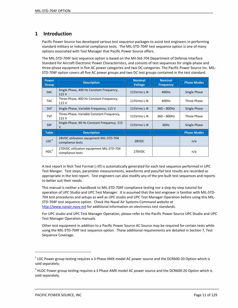
1 Introduction Pacific Power Source has developed various test sequence packages to assist test engineers in performing standard military or industrial compliance tests. The MIL-STD-704F test sequence option is one of many options associated with Test Manager that Pacific Power Source offers.
The MIL-STD-704F test sequence option is based on the Mil-Std-704 Department of Defense Interface Standard for Aircraft Electronic Power Characteristics, and consists of test sequences for single-phase and three-phase equipment in five AC power categories and two DC categories. The Pacific Power Source Inc. MIL-STD-704F option covers all five AC power groups and two DC test groups contained in the test standard.
Power Group Description Nominal
Voltage Nominal
Frequency Phase Modes
SAC Single-Phase, 400 Hz Constant Frequency, 115 V 115Vrms L-N 400Hz Single Phase
TAC Three-Phase, 400 Hz Constant Frequency, 115 V 115Vrms L-N 400Hz Three Phase
SVF Single-Phase, Variable Frequency, 115 V 115Vrms L-N 360 – 800Hz Single Phase
TVF Three-Phase, Variable Constant Frequency, 115 V 115Vrms L-N 360 – 800Hz Three Phase
SXF Single-Phase, 60 Hz Constant Frequency, 115 V 115Vrms L-N 60Hz Single Phase
Table Description Phase Modes
LDC1 28VDC utilization equipment MIL-STD-704 compliance tests 28VDC n/a
HDC2 270VDC utilization equipment MIL-STD-704 compliance tests 270VDC n/a
A test report in Rich Text Format (.rtf) is automatically generated for each test sequence performed in UPC Test Manger. Test steps, parameter measurements, waveforms and pass/fail test results are recorded as appropriate in the test report. Test engineers can also modify any of the pre-built test sequences and reports to better suit their needs.
This manual is neither a handbook to MIL-STD-704F compliance testing nor a step-by-step tutorial for operation of UPC Studio and UPC Test Manager. It is assumed that the test engineer is familiar with MIL-STD-704 test procedures and setups as well as UPC studio and UPC Test Manager Operation before using this MIL-STD-704F test sequence option. Check the Naval Air Systems Command website at http://www.navair.navy.mil for additional information on electronics test standards.
For UPC studio and UPC Test Manager Operation, please refer to the Pacific Power Source UPC Studio and UPC Test Manager Operation manuals.
Other test equipment in addition to a Pacific Power Source AC Source may be required for certain tests while using the MIL-STD-704F test sequence option. These additional requirements are detailed in Section 7, Test Sequence Coverage.
1 LDC Power group testing requires a 3 Phase AMX model AC power source and the DCR600-20 Option which is sold separately. 2 HLDC Power group testing requires a 3 Phase AMX model AC power source and the DCR600-20 Option which is sold separately.
MIL-STD-704F OPTION
PACIFIC POWER SOURCE, INC Page 12 of 129
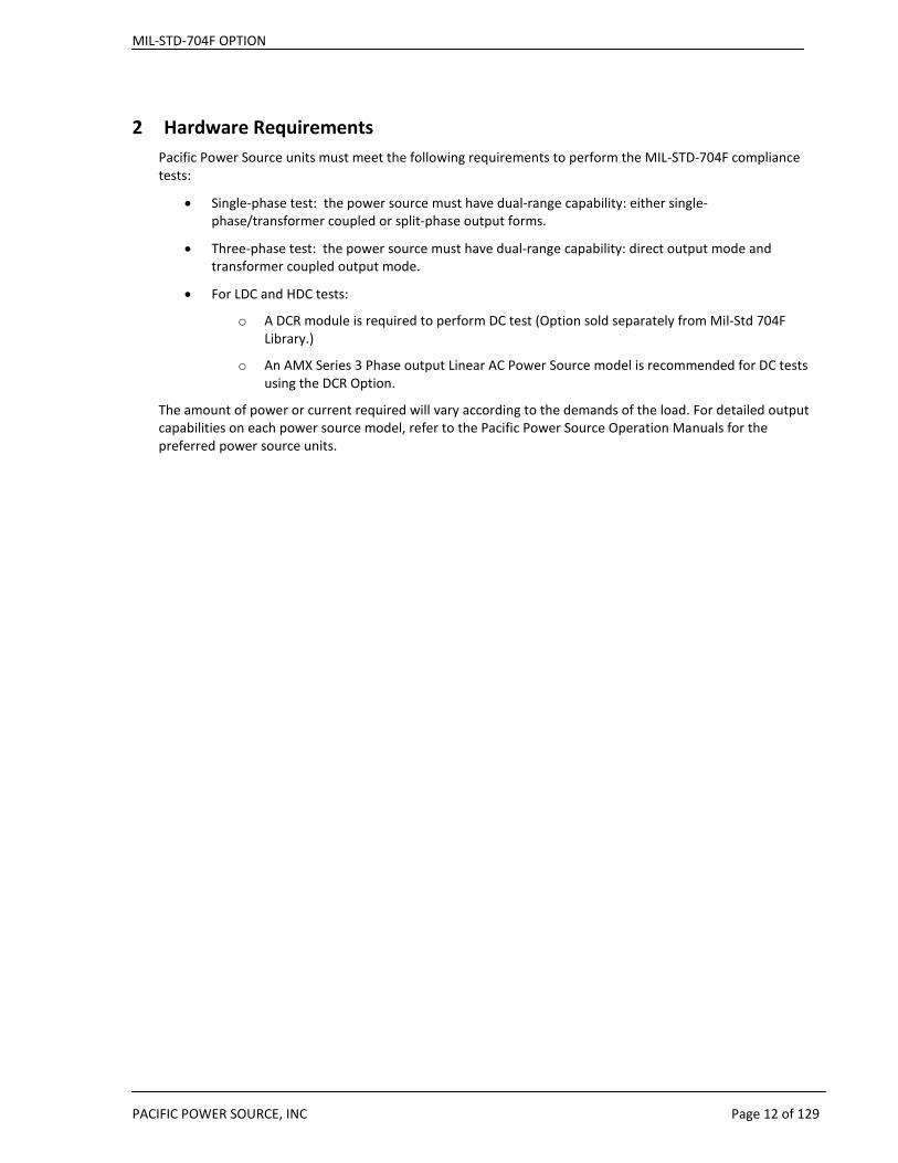
2 Hardware Requirements Pacific Power Source units must meet the following requirements to perform the MIL-STD-704F compliance tests:
• Single-phase test: the power source must have dual-range capability: either single-phase/transformer coupled or split-phase output forms.
• Three-phase test: the power source must have dual-range capability: direct output mode and transformer coupled output mode.
• For LDC and HDC tests:
o A DCR module is required to perform DC test (Option sold separately from Mil-Std 704F Library.)
o An AMX Series 3 Phase output Linear AC Power Source model is recommended for DC tests using the DCR Option.
The amount of power or current required will vary according to the demands of the load. For detailed output capabilities on each power source model, refer to the Pacific Power Source Operation Manuals for the preferred power source units.
MIL-STD-704F OPTION
PACIFIC POWER SOURCE, INC Page 13 of 129
3 Software Installation The MIL-STD-704F test sequence is distributed as a single install program. The following executable file constitutes the MIL-STD-704F Option package:
149101-MIL-STD-704F Test Suite v1.0.exe
Note: The version number “v1.0” may vary as new updates are released.
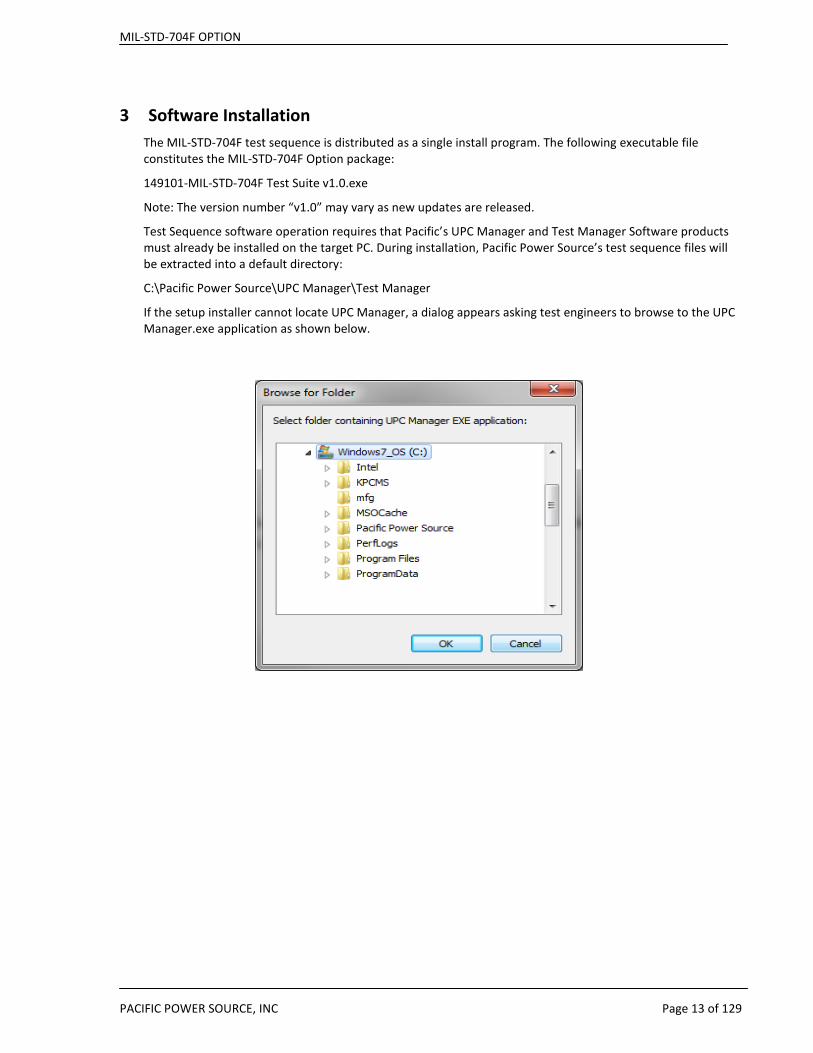
Test Sequence software operation requires that Pacific’s UPC Manager and Test Manager Software products must already be installed on the target PC. During installation, Pacific Power Source’s test sequence files will be extracted into a default directory:
C:\Pacific Power Source\UPC Manager\Test Manager
If the setup installer cannot locate UPC Manager, a dialog appears asking test engineers to browse to the UPC Manager.exe application as shown below.
MIL-STD-704F OPTION
PACIFIC POWER SOURCE, INC Page 14 of 129
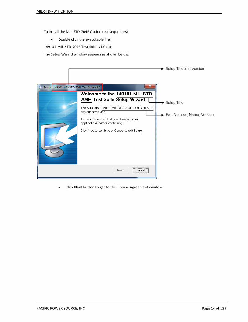
To install the MIL-STD-704F Option test sequences:
• Double click the executable file:
149101-MIL-STD-704F Test Suite v1.0.exe
The Setup Wizard window appears as shown below.
• Click Next button to get to the License Agreement window.
MIL-STD-704F OPTION
PACIFIC POWER SOURCE, INC Page 15 of 129
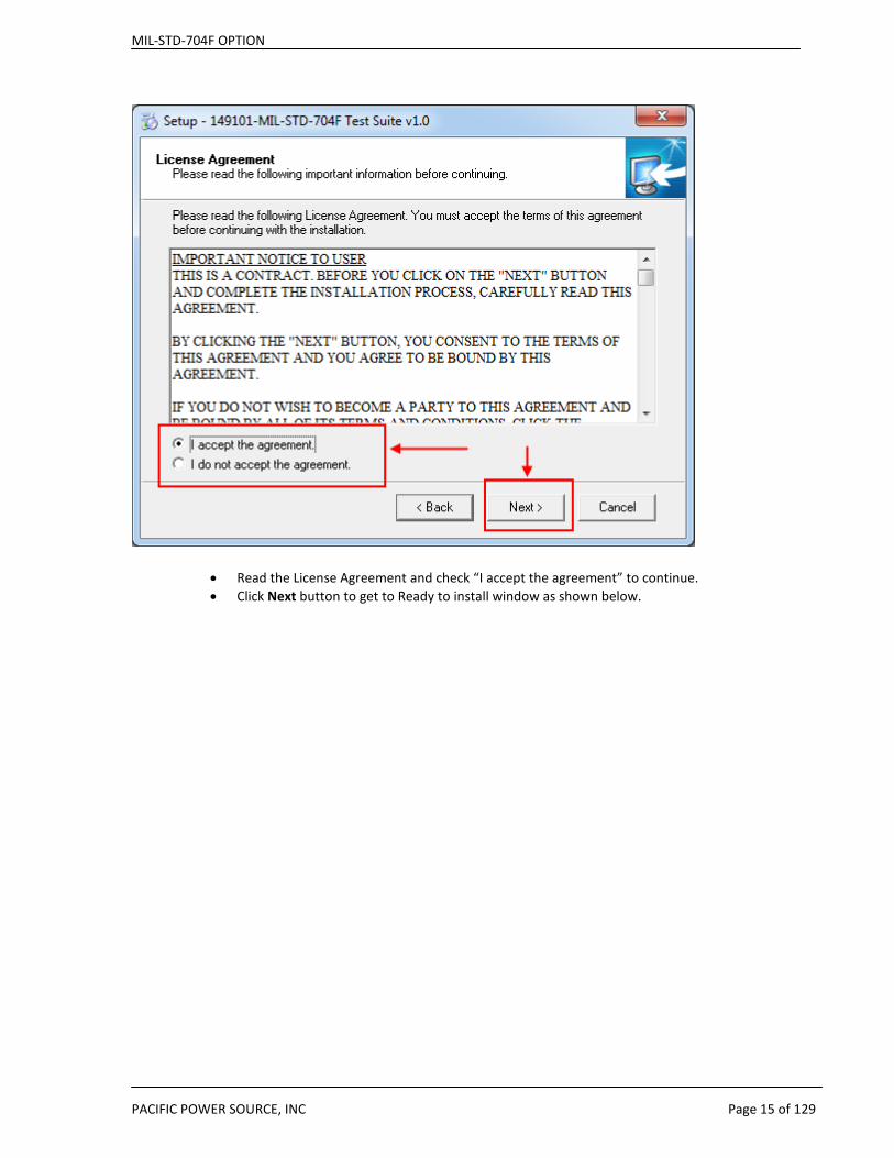
• Read the License Agreement and check “I accept the agreement” to continue. • Click Next button to get to Ready to install window as shown below.
MIL-STD-704F OPTION
PACIFIC POWER SOURCE, INC Page 16 of 129
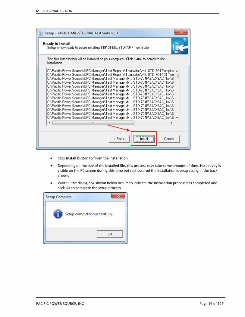
• Click Install button to finish the installation.
• Depending on the size of the installed file, this process may take some amount of time. No activity is visible on the PC screen during this time but rest assured the installation is progressing in the back ground.
• Wait till the dialog box shown below occurs to indicate the installation process has completed and click OK to complete the setup process.

MIL-STD-704F OPTION
PACIFIC POWER SOURCE, INC Page 17 of 129
4 Software Removal To uninstall MIL-STD-704F test sequence files or packages:
• Navigate to the directory where the test sequence files or folder are saved.
• Delete the desired files or folders from the directory.
Note: There are no Windows® System files or registration entries associated with the test sequences so no uninstall program is required to remove the option files from a PC.
MIL-STD-704F OPTION
PACIFIC POWER SOURCE, INC Page 18 of 129
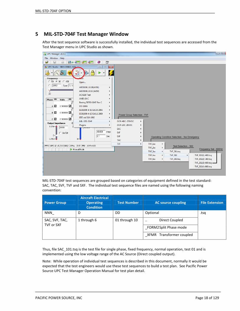
5 MIL-STD-704F Test Manager Window After the test sequence software is successfully installed, the individual test sequences are accessed from the Test Manager menu in UPC Studio as shown.
MIL-STD-704F test sequences are grouped based on categories of equipment defined in the test standard: SAC, TAC, SVF, TVF and SXF. The individual test sequence files are named using the following naming convention:
Power Group Aircraft Electrical
Operating Condition
Test Number AC source coupling File Extension
NNN_ D DD Optional .tsq
SAC, SVF, TAC, TVF or SXF
1 through 6 01 through 10 .. Direct Coupled
_FORM2 Split Phase mode
_XFMR Transformer coupled
Thus, file SAC_101.tsq is the test file for single phase, fixed frequency, normal operation, test 01 and is implemented using the low voltage range of the AC Source (Direct coupled output).
Note: While operation of individual test sequences is described in this document, normally it would be expected that the test engineers would use these test sequences to build a test plan. See Pacific Power Source UPC Test Manager Operation Manual for test plan detail.

MIL-STD-704F OPTION
PACIFIC POWER SOURCE, INC Page 19 of 129
6 MIL-STD-704F Test Sequence Windows A typical test sequence is organized in five windows/ tabs: Objective, Preferences, Step Value / Comment, Step Result, and Test Report. The content and purpose of these windows are described in the following sections. For more definition of each field see Pacific Power Source UPC Test Manager Operation Manual.
6.1 Objective Window In the Objective window, illustrated below, the MIL-STD-704F section number, power group, operating condition, test purpose and time period, and parameter setup values are described in detail.
MIL-STD-704F OPTION
PACIFIC POWER SOURCE, INC Page 20 of 129
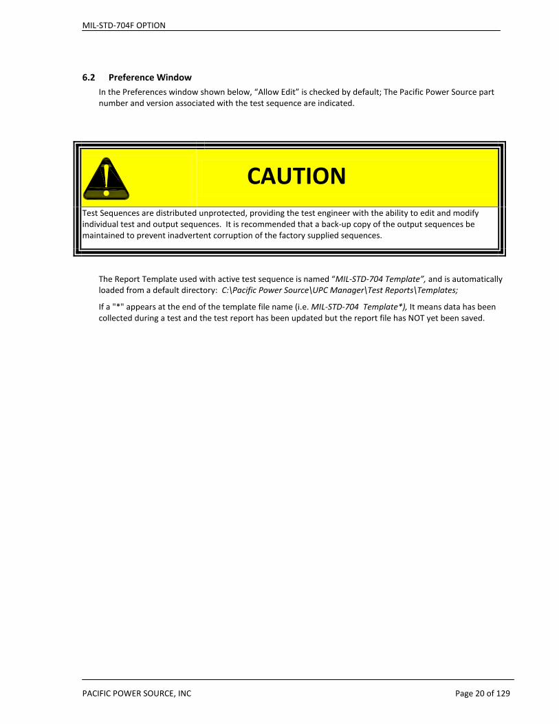
6.2 Preference Window In the Preferences window shown below, “Allow Edit” is checked by default; The Pacific Power Source part number and version associated with the test sequence are indicated.
The Report Template used with active test sequence is named “MIL-STD-704 Template”, and is automatically loaded from a default directory: C:\Pacific Power Source\UPC Manager\Test Reports\Templates;
If a "*" appears at the end of the template file name (i.e. MIL-STD-704 Template*), It means data has been collected during a test and the test report has been updated but the report file has NOT yet been saved.
CAUTION
Test Sequences are distributed unprotected, providing the test engineer with the ability to edit and modify individual test and output sequences. It is recommended that a back-up copy of the output sequences be maintained to prevent inadvertent corruption of the factory supplied sequences.

MIL-STD-704F OPTION
PACIFIC POWER SOURCE, INC Page 21 of 129
MIL-STD-704F OPTION
PACIFIC POWER SOURCE, INC Page 22 of 129
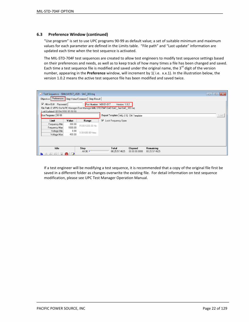
6.3 Preference Window (continued) “Use program” is set to use UPC programs 90-99 as default value; a set of suitable minimum and maximum values for each parameter are defined in the Limits table. “File path” and “Last update” information are updated each time when the test sequence is activated.
The MIL-STD-704F test sequences are created to allow test engineers to modify test sequence settings based on their preferences and needs, as well as to keep track of how many times a file has been changed and saved. Each time a test sequence file is modified and saved under the original name, the 3rd digit of the version number, appearing in the Preference window, will increment by 1( i.e. x.x.1). In the illustration below, the version 1.0.2 means the active test sequence file has been modified and saved twice.
If a test engineer will be modifying a test sequence, it is recommended that a copy of the original file first be saved in a different folder as changes overwrite the existing file. For detail information on test sequence modification, please see UPC Test Manager Operation Manual.
MIL-STD-704F OPTION
PACIFIC POWER SOURCE, INC Page 23 of 129
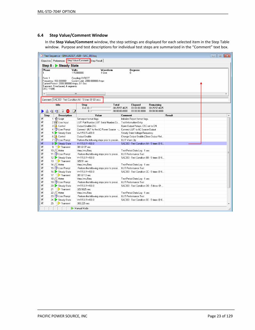
6.4 Step Value/Comment Window In the Step Value/Comment window, the step settings are displayed for each selected item in the Step Table window. Purpose and test descriptions for individual test steps are summarized in the “Comment” text box.
MIL-STD-704F OPTION
PACIFIC POWER SOURCE, INC Page 24 of 129
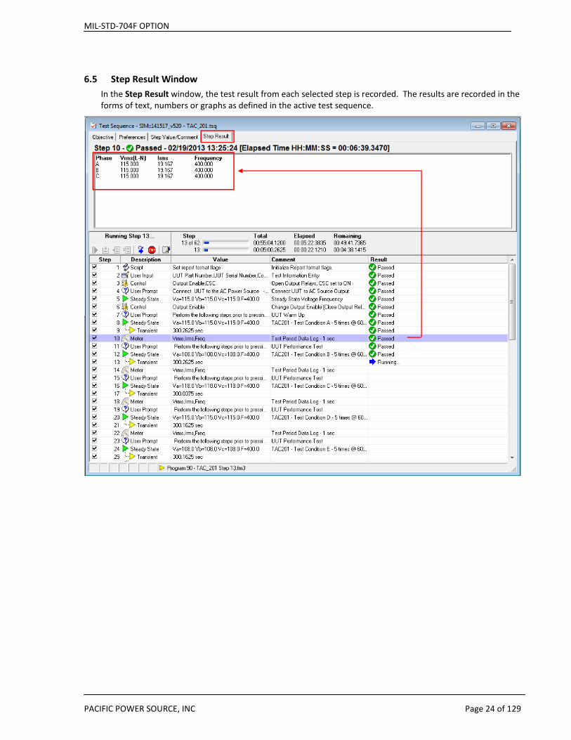
6.5 Step Result Window In the Step Result window, the test result from each selected step is recorded. The results are recorded in the forms of text, numbers or graphs as defined in the active test sequence.
MIL-STD-704F OPTION
PACIFIC POWER SOURCE, INC Page 25 of 129
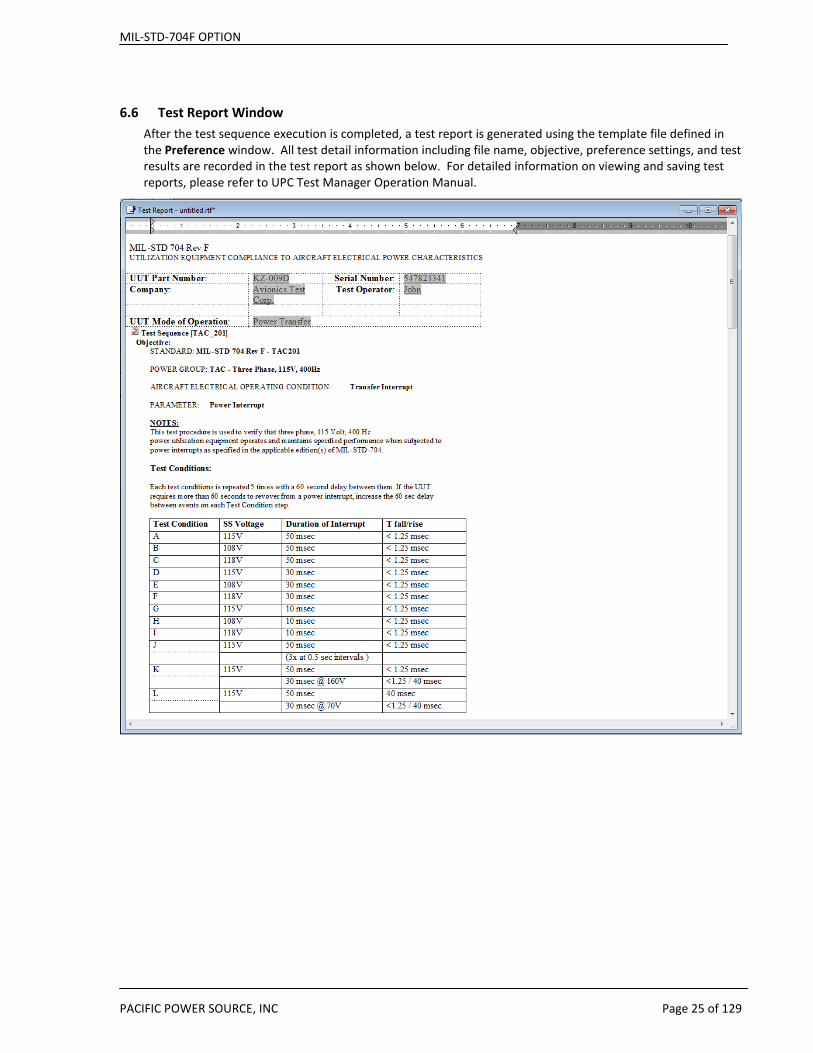
6.6 Test Report Window After the test sequence execution is completed, a test report is generated using the template file defined in the Preference window. All test detail information including file name, objective, preference settings, and test results are recorded in the test report as shown below. For detailed information on viewing and saving test reports, please refer to UPC Test Manager Operation Manual.
MIL-STD-704F OPTION
PACIFIC POWER SOURCE, INC Page 26 of 129
7 Test Reports Test reports are automatically created as each test sequence is executed. Generally, information contained in each step is added to the report as each step is executed. This includes the step type, parameters set, any measurement values recorded, comments and the result of each step (Pass or Fail).
Test reports can be used as is or further customized by the user. This chapter covers some of the possible changes that can be made as needed.
7.1 Template Files Reports are based on a report template that is installed at the same time as the test sequences in the following directory:
“C:\Pacific Power Source\UPC Manager\Test Reports\Templates”
Template files can be blank or contain introductory text, graphics, form fields, page / paragraph / character formatting, page header and footer (page numbering, date etc.).
7.2 Report Entries Running a test sequence or test plan appends the results of each step at the end of test report. Running a test sequence from the beginning (using the Start icon in the Run Toolbar) initializes the test report from the selected template file then adds the test sequence Objective and Preferences. This creates a clean report each time the test sequence is run. Running a test sequence using the other controls does not clear the test report or add the Objective or Preferences, making it easier to troubleshoot (single step etc.) a test.
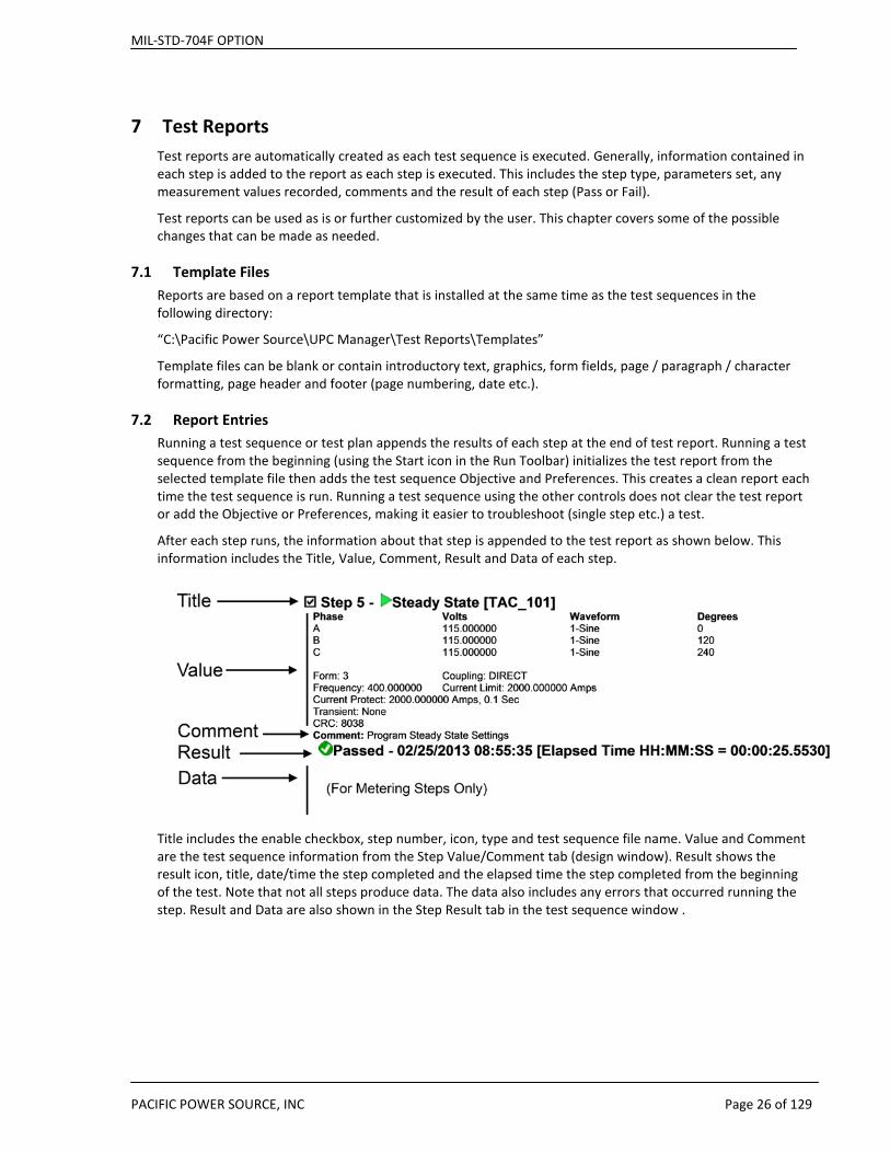
After each step runs, the information about that step is appended to the test report as shown below. This information includes the Title, Value, Comment, Result and Data of each step.
Title includes the enable checkbox, step number, icon, type and test sequence file name. Value and Comment are the test sequence information from the Step Value/Comment tab (design window). Result shows the result icon, title, date/time the step completed and the elapsed time the step completed from the beginning of the test. Note that not all steps produce data. The data also includes any errors that occurred running the step. Result and Data are also shown in the Step Result tab in the test sequence window .
MIL-STD-704F OPTION
PACIFIC POWER SOURCE, INC Page 27 of 129
7.3 Customizing Test Reports There are several ways to customize test reports. Some possibilities are:
1. Change Headers and or Footers
2. Select which test steps to include in a report or how much information from each test step to include or exclude from the report.
3. Reformat layout, format tables and or fonts after the report is saved.
7.3.1 Report Template Headers and Footers The provided MIL-STD-704F Report template files contain a simple footer which contains only basic information and no header.
The footer contains the following information.
Pacific Power Source, Inc. 27 of 129 9/12/2013 9:30:22 AM 149153-10_MIL-STD-704F Option Manual.doc v1.0.0 Irvine CA, USA
A Header can be added by opening either of the two provided template files using MS Word.
MIL-STD 704 Template.rtf
MIL-STD 704 101 Template.rtf
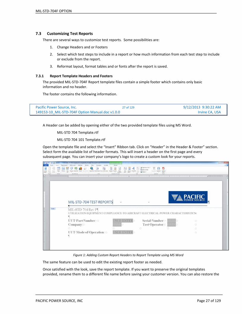
Open the template file and select the “Insert” Ribbon tab. Click on “Header” in the Header & Footer” section. Select form the available list of header formats. This will insert a header on the first page and every subsequent page. You can insert your company’s logo to create a custom look for your reports.
Figure 1: Adding Custom Report Headers to Report Template using MS Word
The same feature can be used to edit the existing report footer as needed.
Once satisfied with the look, save the report template. If you want to preserve the original templates provided, rename them to a different file name before saving your customer version. You can also restore the
MIL-STD-704F OPTION
PACIFIC POWER SOURCE, INC Page 28 of 129
original report template files by re-installing the MIL-STD-704F option but this will also re-install all test sequences.
7.3.2 Customizing Report Content using VB Script Steps The VB Scripting feature of the UPC Test Manager program may be used to selectively exclude all or part of a test report entry. Most of the provided MIL-STD-704F test sequences use this feature in Step #1.
The available flags that can be set or cleared to include or exclude a specific test step report entry are covered by the UPC Studio on-line Help file and are not repeated in this manual. Search the Help file Index tab for “Script” to find the relevant information.
MIL-STD-704F OPTION
PACIFIC POWER SOURCE, INC Page 29 of 129
7.3.3 Editing existing Reports As a rule, test reports generated by executing a test sequence are locked and cannot be edited. If needed, it is possible to unlock a report in order to add additional information or format data is a different way than the standard report provides.
To edit an existing test report, proceed as follows:
1. Complete the test sequence and save the report when prompted as the end of the test sequence.
2. Use MS Word to open the file located in the Reports directory of UPC Studio, typically: C:\Pacific Power Source\UPC Manager\Test Reports
3. Clicking with the mouse on any area or page of the test report will take you to the top of the first page of the report. This is due to the fact that all sections of the report are restricted for editing.
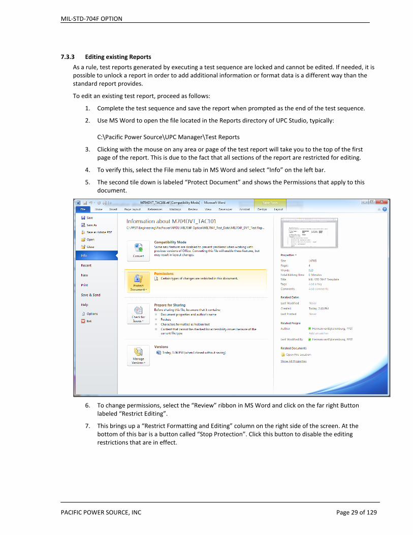
4. To verify this, select the File menu tab in MS Word and select “Info” on the left bar.
5. The second tile down is labeled “Protect Document” and shows the Permissions that apply to this document.
6. To change permissions, select the “Review” ribbon in MS Word and click on the far right Button
labeled “Restrict Editing”.
7. This brings up a “Restrict Formatting and Editing” column on the right side of the screen. At the bottom of this bar is a button called “Stop Protection”. Click this button to disable the editing restrictions that are in effect.

MIL-STD-704F OPTION
PACIFIC POWER SOURCE, INC Page 30 of 129
8. Once unlocked, changes may be made to any test step. For example, the Harmonic measurement
data at TAC_101, Step 11 which runs beyond the page margin can be reformatted to a table layout for a more pleasing view of the data. Also, the header information could be removed as the selected harmonics will be evident from the measurement data. Below is what the step 11 entry in the report.
9. Deleting the Value section of Step 11 and converting the tab delimited measurement data to a Word
table yields the result shown below.

MIL-STD-704F OPTION
PACIFIC POWER SOURCE, INC Page 31 of 129
10. When all formatting changes are completed, you can lock down the file using the same “Restrict
Formatting and Editing” column on the right side of the screen.
11. To set back to the original report restrictions, Select 2. Editing restrictions and check the box “Allow only this type of editing in the document:”. Select “Filling in forms” from the dropdown box and click the “Yes, Start Enforcing Protection” button below.
12. When prompted for a password, you can provide one if desired or leave blank and click on the OK button. Leaving password field blank means no password is required to unlock the document.
13. Any changes should be saved using the orignal file name that was assigned when first created.
MIL-STD-704F OPTION
PACIFIC POWER SOURCE, INC Page 32 of 129
8 MIL-STD-704F Test Application Considerations This section explains several implementation and application specific considerations that apply to some of the MIL-STD-704F test sequence implementations.
While most test methods are relatively straightforward in that they apply a sequence of voltage and frequency setting for a set period of time, some test require additional equipment and hardware to set up and run. This chapter describes some of these test methods as defined by their number xxxNNN, where “xxx” stands for the various Power Groups supported and “NNN” for the test number.
8.1 Transition Time Setting – Most xVF Tests The MIL-STD-704F option test sequences for variable frequency power groups were implemented using the UPC Controller Transient Time function to prevent sudden frequency jumps during testing. In particular when changing from one steady state frequency condition to a different, a delta of up to 400Hz may be executed. Such a large frequency jump could damage UUT’s, especially those that have motors or other electromechanical components. To avoid potential damage to the UUT, frequency change other than those called out specifically in the Mil-Std-704 test standard are executed with a frequency slew rate of no more than 10Hz/sec. Thus when changing between a 800Hz test condition and a 400Hz test condition, the slew time will be 40 seconds. This setting is generally effected in the second test step of each xVF test sequence.
Since the Transient Time setting on the UPC controller is a global setting and remains in effect until changed, at the end of each variable frequency test sequence (SVF and TVF power groups), the transient time on the UPC controller is set back to zero. This means any programmed changes for voltage or frequency made by the user from the front panel or over the bus between test runs will occur instantaneously, which is generally the default setting.
If however a test is aborted prematurely and not allowed to complete through its final test steps, the Transient Time parameter will remain at its set value.
The test Objective Tab message of those test sequences that use a Transition Time setting other than 0.0 secs contains a message to this affect.
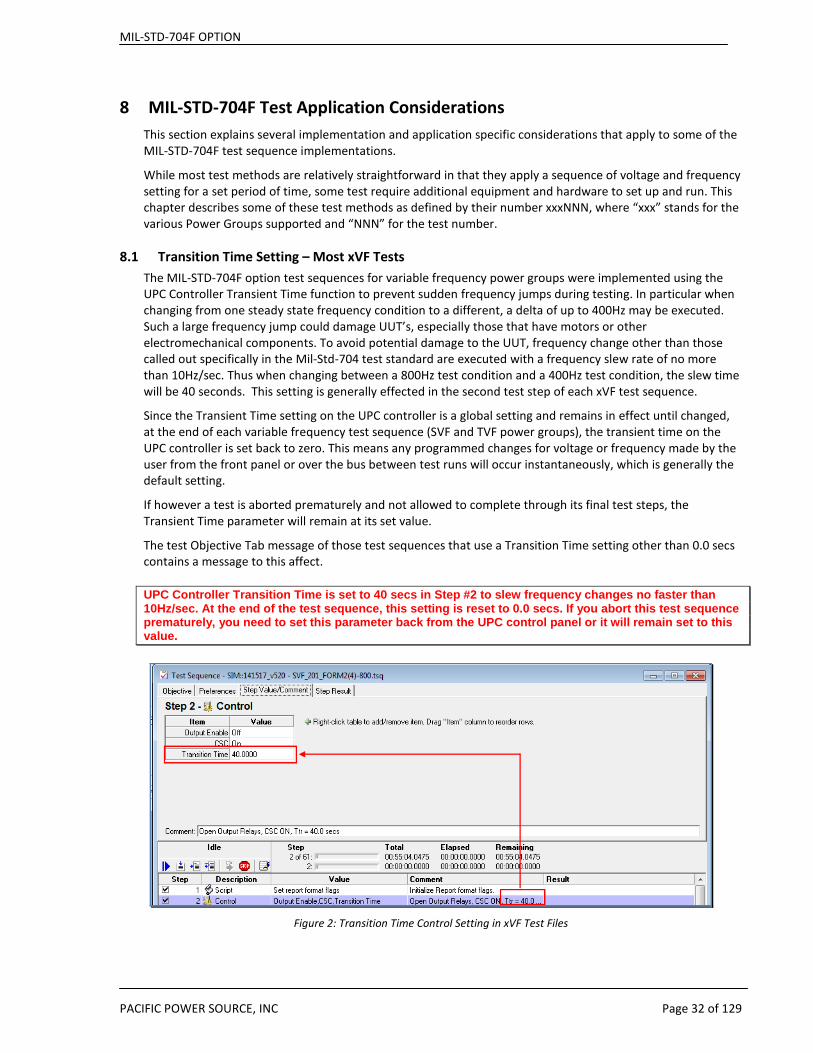
UPC Controller Transition Time is set to 40 secs in Step #2 to slew frequency changes no faster than 10Hz/sec. At the end of the test sequence, this setting is reset to 0.0 secs. If you abort this test sequence prematurely, you need to set this parameter back from the UPC control panel or it will remain set to this value.
Figure 2: Transition Time Control Setting in xVF Test Files

MIL-STD-704F OPTION
PACIFIC POWER SOURCE, INC Page 33 of 129
8.2 Method xxx101 – Load Measurements This test is performed to characterize the UUT load characteristics. It is done by applying nominal voltage (115Vac RMS L-N / 200Vac RMS L-L) and nominal frequency based on power group:
Power Groups Test Frequencies
SAC and TAC 400Hz
SXF 60Hz
SVF and TVD 400Hz, 360Hz, 600Hz and 800Hz
LDC and HDC DC
8.2.1 Additional Measurement Equipment Because the main focus of this test is to capture voltage and current parameters and waveforms, it is recommended to use additional measurement equipment to augment the measurement functions of the AC Power Source used. In particular, in-rush current may be better documented by capturing it on a digital storage scope of using a dedicated high precision power analyzer that has this functionality built in. Although all measurement data required for this test is acquired by the AC Power Source as part of the xxx101 test, a digital scope with higher resolution than the UPC controller is recommended to verify the current wave shape and check for half wave rectification at the UUT AC input.
8.2.2 Test Setups xxx101 The recommended test setup for single phase UUT testing is shown in Figure 3 below.
Figure 3: Method xxx101 Single Phase UUT Test Setup
MIL-STD-704F OPTION
PACIFIC POWER SOURCE, INC Page 34 of 129
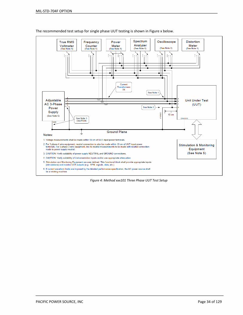
The recommended test setup for single phase UUT testing is shown in Figure x below.
Figure 4: Method xxx101 Three Phase UUT Test Setup
MIL-STD-704F OPTION
PACIFIC POWER SOURCE, INC Page 35 of 129
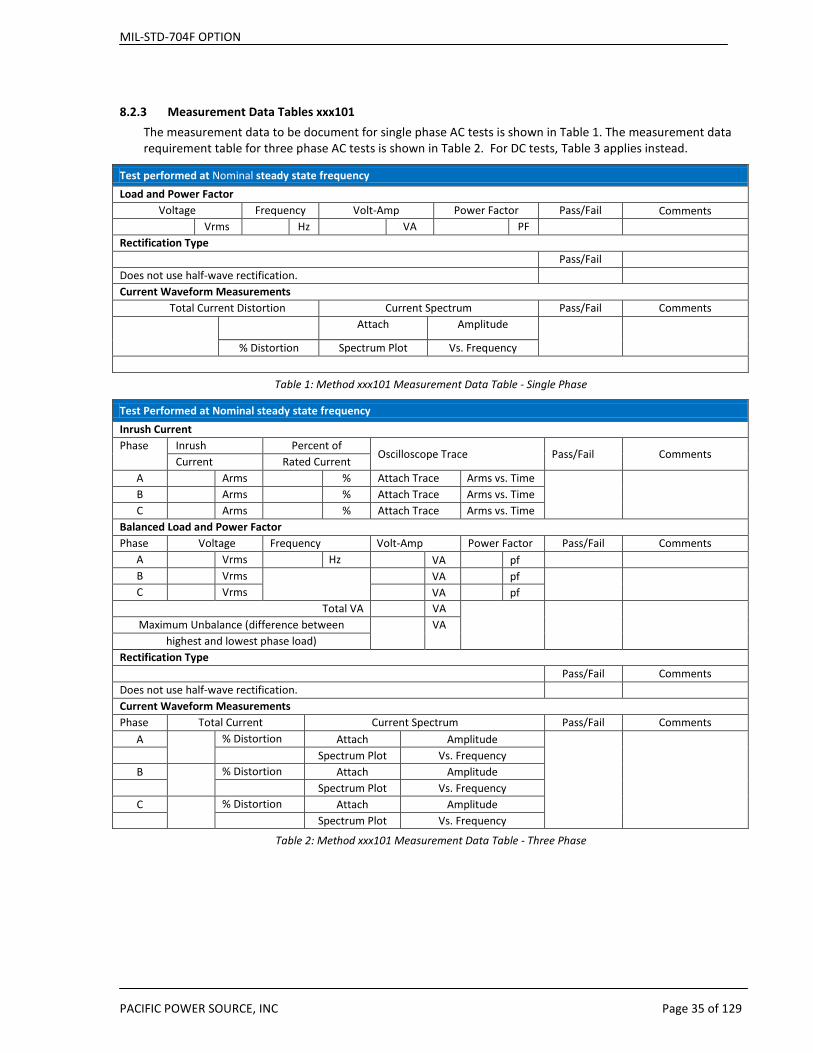
8.2.3 Measurement Data Tables xxx101 The measurement data to be document for single phase AC tests is shown in Table 1. The measurement data requirement table for three phase AC tests is shown in Table 2. For DC tests, Table 3 applies instead.
Test performed at Nominal steady state frequency Load and Power Factor
Voltage Frequency Volt-Amp Power Factor Pass/Fail Comments Vrms Hz VA PF
Rectification Type Pass/Fail
Does not use half-wave rectification. Current Waveform Measurements
Total Current Distortion Current Spectrum Pass/Fail Comments Attach Amplitude
% Distortion Spectrum Plot Vs. Frequency
Table 1: Method xxx101 Measurement Data Table - Single Phase
Test Performed at Nominal steady state frequency Inrush Current Phase Inrush Percent of
Oscilloscope Trace Pass/Fail Comments Current Rated Current
A Arms % Attach Trace Arms vs. Time B Arms % Attach Trace Arms vs. Time C Arms % Attach Trace Arms vs. Time
Balanced Load and Power Factor Phase Voltage Frequency Volt-Amp Power Factor Pass/Fail Comments
A Vrms Hz VA pf B Vrms VA pf
C Vrms VA pf Total VA VA
Maximum Unbalance (difference between VA highest and lowest phase load)
Rectification Type Pass/Fail Comments Does not use half-wave rectification. Current Waveform Measurements Phase Total Current
Current Spectrum Pass/Fail Comments
A % Distortion Attach Amplitude
Spectrum Plot Vs. Frequency
B % Distortion Attach Amplitude
Spectrum Plot Vs. Frequency
C % Distortion Attach Amplitude
Spectrum Plot Vs. Frequency
Table 2: Method xxx101 Measurement Data Table - Three Phase
MIL-STD-704F OPTION
PACIFIC POWER SOURCE, INC Page 36 of 129
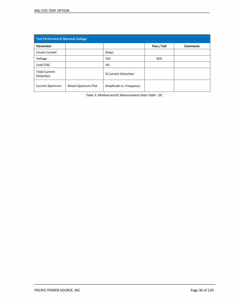
Test Performed at Nominal Voltage
Parameter Pass / Fail Comments
Inrush Current Amps
Voltage Vdc N/A Load (VA) VA
Total Current Distortion % Current Distortion
Current Spectrum Attach Spectrum Plot Amplitude vs. Frequency
Table 3: Method xxx101 Measurement Data Table - DC
MIL-STD-704F OPTION
PACIFIC POWER SOURCE, INC Page 37 of 129
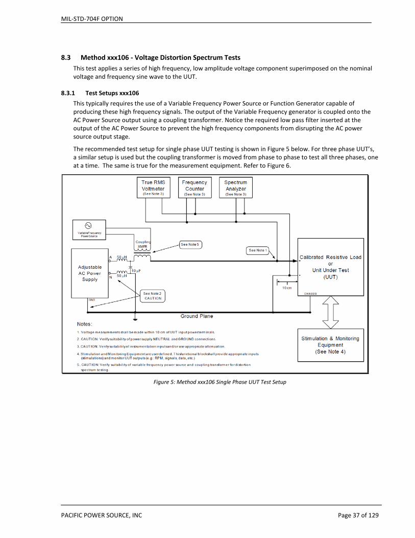
8.3 Method xxx106 - Voltage Distortion Spectrum Tests This test applies a series of high frequency, low amplitude voltage component superimposed on the nominal voltage and frequency sine wave to the UUT.
8.3.1 Test Setups xxx106 This typically requires the use of a Variable Frequency Power Source or Function Generator capable of producing these high frequency signals. The output of the Variable Frequency generator is coupled onto the AC Power Source output using a coupling transformer. Notice the required low pass filter inserted at the output of the AC Power Source to prevent the high frequency components from disrupting the AC power source output stage.
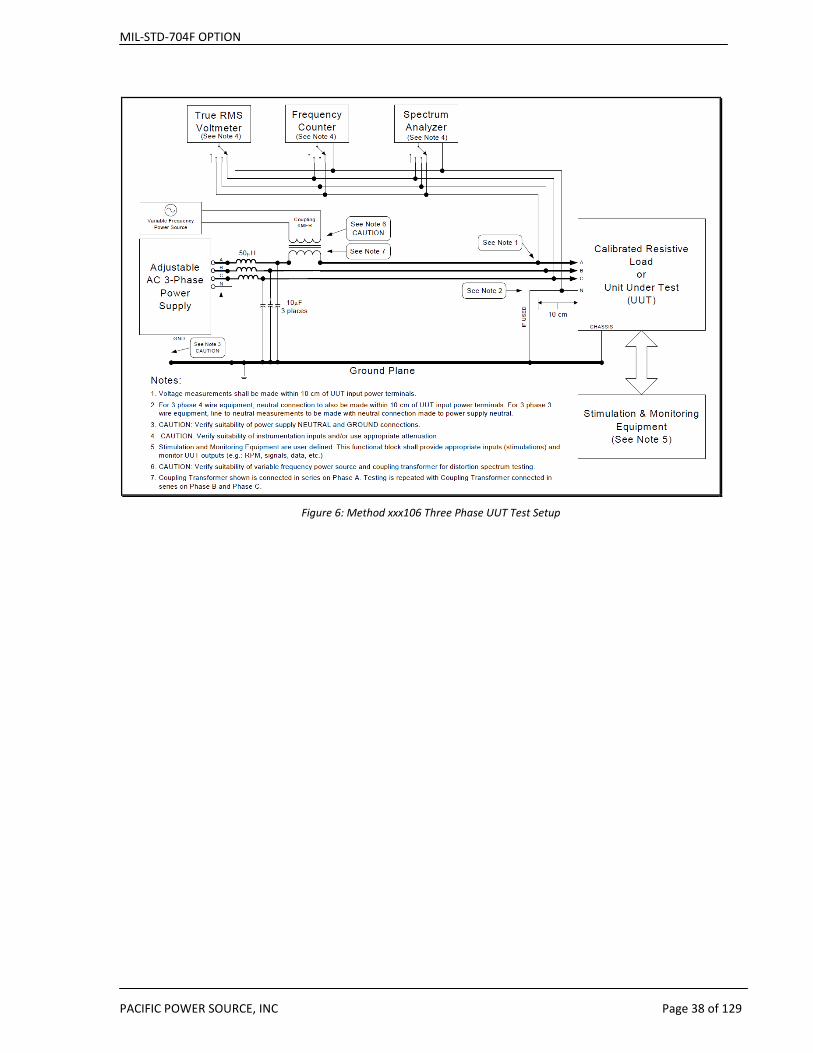
The recommended test setup for single phase UUT testing is shown in Figure 5 below. For three phase UUT’s, a similar setup is used but the coupling transformer is moved from phase to phase to test all three phases, one at a time. The same is true for the measurement equipment. Refer to Figure 6.
Figure 5: Method xxx106 Single Phase UUT Test Setup
MIL-STD-704F OPTION
PACIFIC POWER SOURCE, INC Page 38 of 129
Figure 6: Method xxx106 Three Phase UUT Test Setup
MIL-STD-704F OPTION
PACIFIC POWER SOURCE, INC Page 39 of 129
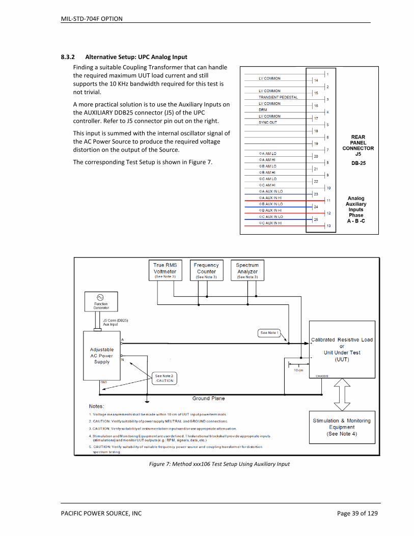
8.3.2 Alternative Setup: UPC Analog Input Finding a suitable Coupling Transformer that can handle the required maximum UUT load current and still supports the 10 KHz bandwidth required for this test is not trivial.
A more practical solution is to use the Auxiliary Inputs on the AUXILIARY DDB25 connector (J5) of the UPC controller. Refer to J5 connector pin out on the right.
This input is summed with the internal oscillator signal of the AC Power Source to produce the required voltage distortion on the output of the Source.
The corresponding Test Setup is shown in Figure 7.
Figure 7: Method xxx106 Test Setup Using Auxiliary Input

MIL-STD-704F OPTION
PACIFIC POWER SOURCE, INC Page 40 of 129
Note that the gain of the Analog Input is 25 for FORM1 or FORM3 mode of operation so the output of the Variable Frequency generator must be set to a suitable level as indicated in the last column of the table below for the TVF106 tests. For three phase applications, the voltage distortion is applied one phase at a time so only a single Variable Frequency generator is required.
Test Condition Frequency of Voltage Distortion
Amplitude of Voltage Distortion (Vrms)
Amplitude of Analog Input Signal (mVrms)
A 50 Hz 0.316 12.64 B 100 Hz 0.316 12.64 C 500 Hz 1.580 63.2 D 1 kHz 3.160 3.160 E 2 kHz 3.160 126.4 F 3 kHz 3.160 126.4 G 5 kHz 1.900 76.0 H 10 kHz 0.950 38.0
8.3.3 Measurements xxx106 The measurement data to be document for single phase (Phase A) is shown in Table 9. For three phase UUT’s, measurement data is acquired for each phase (Phase A, B, C).
Test Condition Parameters Performance Voltage Frequency Frequency of
Voltage Distortion
Amplitude of Voltage
Distortion
Time Duration at
test condition
Pass/Fail
Testing performed at Nominal Frequency (SAC, TAC, SXF) or Frequencies (SVF, TVF)
A Vrms Hz Hz Vrms min B Vrms Hz Hz Vrms min C Vrms Hz Hz Vrms min D Vrms Hz kHz Vrms min E Vrms Hz kHz Vrms min F Vrms Hz kHz Vrms min G Vrms Hz kHz Vrms min H Vrms Hz kHz Vrms min
Table 4: Method xxx106 Measurement Data Table - Single Phase
MIL-STD-704F OPTION
PACIFIC POWER SOURCE, INC Page 41 of 129
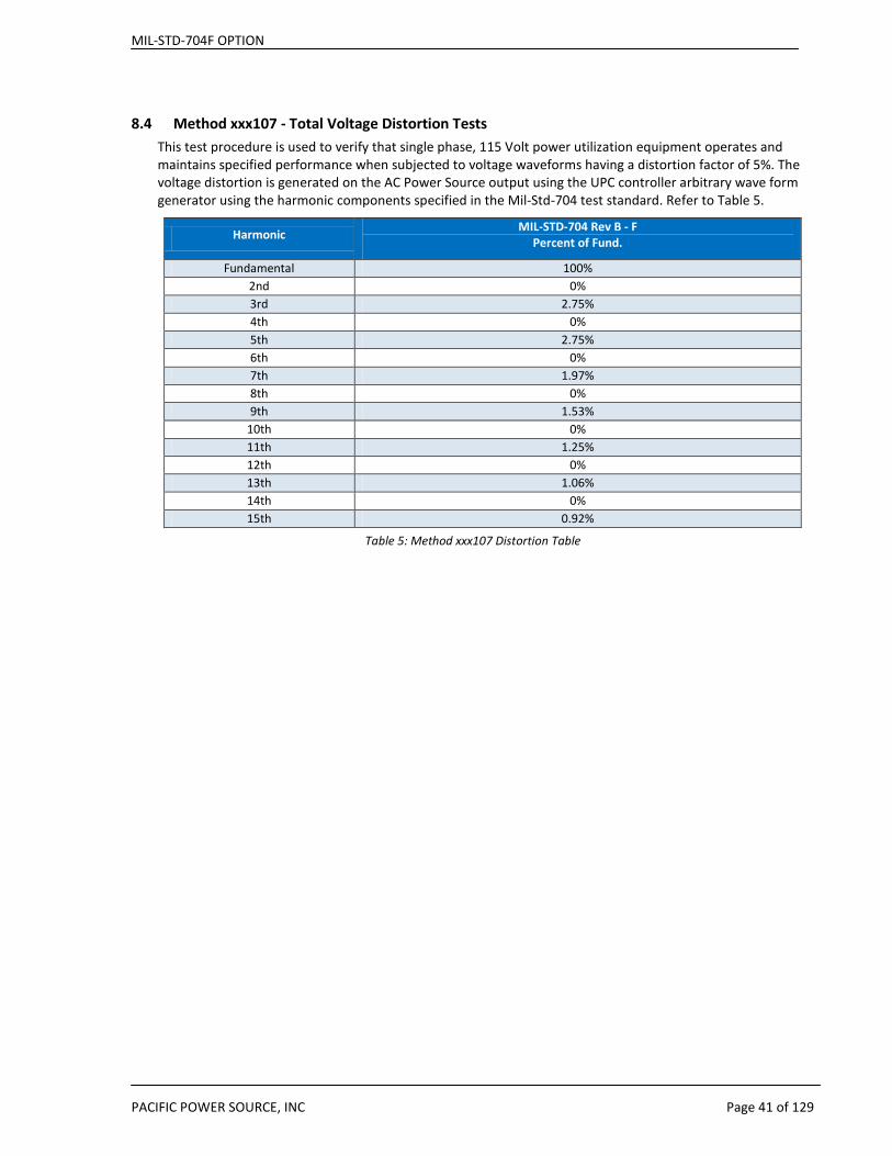
8.4 Method xxx107 - Total Voltage Distortion Tests This test procedure is used to verify that single phase, 115 Volt power utilization equipment operates and maintains specified performance when subjected to voltage waveforms having a distortion factor of 5%. The voltage distortion is generated on the AC Power Source output using the UPC controller arbitrary wave form generator using the harmonic components specified in the Mil-Std-704 test standard. Refer to Table 5.
Harmonic MIL-STD-704 Rev B - F Percent of Fund.
Fundamental 100% 2nd 0% 3rd 2.75% 4th 0% 5th 2.75% 6th 0% 7th 1.97% 8th 0% 9th 1.53%
10th 0% 11th 1.25% 12th 0% 13th 1.06% 14th 0% 15th 0.92%
Table 5: Method xxx107 Distortion Table
MIL-STD-704F OPTION
PACIFIC POWER SOURCE, INC Page 42 of 129
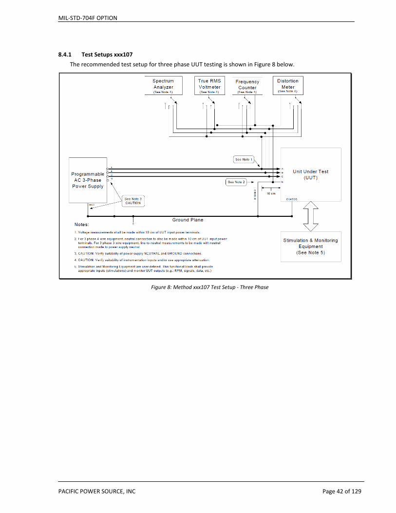
8.4.1 Test Setups xxx107 The recommended test setup for three phase UUT testing is shown in Figure 8 below.
Figure 8: Method xxx107 Test Setup - Three Phase

MIL-STD-704F OPTION
PACIFIC POWER SOURCE, INC Page 43 of 129
8.4.2 Measurements The measurement data to be document for single phase (Phase A) is shown in Table 9. For three phase UUT’s, measurement data is acquired for each phase (Phase A, B, C).
Phase Voltage Frequency Voltage Distortion Factor Time Duration
at Test Condition
Performance Pass/Fail
A Vrms Hz No units min B Vrms No units C Vrms No units
Voltage Harmonics Voltage Harmonics Voltage Harmonics Phase A Phase B Phase C
Fund % Fund % Fund % 2nd % 2nd % 2nd % 3rd % 3rd % 3rd % 4th % 4th % 4th % 5th % 5th % 5th % 6th % 6th % 6th % 7th % 7th % 7th % 8th % 8th % 8th % 9th % 9th % 9th %
10th % 10th % 10th % 11th % 11th % 11th % 12th % 12th % 12th % 13th % 13th % 13th % 14th % 14th % 14th % 15th % 15th % 15th %
MIL-STD-704F OPTION
PACIFIC POWER SOURCE, INC Page 44 of 129
8.5 Method xxx108 - DC Voltage Offset Tests This test procedure is used to verify that single phase, 115 Volt power utilization equipment operates and maintains specified performance when subjected to a direct current component of AC voltage. As such, a small DC offset voltage is applied to each phase using both positive and negative polarity.
While some AC Power Source models of other manufacturers allow for programming a DC offset, the small DC offset value required for Mil-Std-704 testing - + or – 100 mV - can be difficult to produce on an AC power source with a 0.1V programming resolution.
8.5.1 Test Setup – xxx108 A better alternative is to use a low voltage range DC Power Supply in series with the AC power source output. Since most DC Supplies are uni-polar, a polarity reversal relay may be used to change polarity or the connection terminals can be swapped as needed. To electrically remove the DC Power Supplies when not in use, a bypass relay can be used as shown – as long as the output of the DC Supply is off.
It is important that both positive and negative output terminal of the DC Power Supply used are floating (NOT grounded) as the DC supply will be floating on the AC output. Also, isolation between the DC Supplies output terminals and chassis must be higher than 120Vrms.
NOTE: Check with the manufacturer of the DC Power Supplies used what the maximum AC Ripple Current rating of the bulk output capacitors is as these caps will see the UUT AC load current in addition to any DC current drawn by the UUT.
The relevant test setup for three phase UUT’s is shown in Figure 9. For single phase applications, only one DC supply is needed on the Phase A output of the AC Power Source.

MIL-STD-704F OPTION
PACIFIC POWER SOURCE, INC Page 45 of 129
AC
AC
AC
A
B
C
N
AC POWER SOURCE
AC In
put
Apply 3 phase AC Input Power
Bypass Relay
DC Supply
Apply 3 phase AC Input PowerTo DC Supply per Type Label. AC Input = 400Vac L-L.
Polarity Relay
DC Supply
Apply 3 phase AC Input PowerTo DC Supply per Type Label. AC Input = 400Vac L-L.
Polarity Relay
DC Supply
Apply 3 phase AC Input PowerTo DC Supply per Type Label. AC Input = 400Vac L-L.
Polarity Relay
Bypass Relay
Bypass RelayEQUIPMENT UNDER TEST
ABC
N
AC In
put
AC In
put
AC In
put
Figure 9: Method xxx108 DC Offset Test Setup - Three Phase

MIL-STD-704F OPTION
PACIFIC POWER SOURCE, INC Page 46 of 129
8.6 LDC and HDC DC Power Tests These test procedures verify MIL-HDBK-704 Section 7 (HDC) and MIL-HDBK-704 Section 8 (LDC) of aircraft electrical power characteristics. Testing DC products is possible through the use of the optional DCR600-20 output module. The DCR module takes three phase AC power and rectifies it do a DC output. By programming the AC voltage, the DC output voltage can be controlled indirectly.
Note: The DCR is sold as a separate hardware option and not included with the Mil-Std704F Software Library.
8.6.1 DCR Option module The AC/DC rectification performed by the DCR module results in a DC output that not identical in level to the AC RMS value programmed but rather will be about two times higher when using a three phase AC square wave output. Thus, to get 270V DC, program a Line to Neutral voltage of around 135Vac on all three phases in 3 phase mode and select a square wave (Waveform no. 3) instead of a sine wave. This will provide the least amount of AC ripple on the DC output.
The LDC and HDC test sequences were developed with this scaling and waveform selection built in so the correct DC output voltages are obtained. Due to the DCR rectifier’s forward voltage drop, the AC to DC scaling ratios are different for 28Vdc testing versus 270Vdc testing and this is also built in to the provided test sequences.
A Vac to Vdc scale factor of 1.99 is used for LDC28VDC test sequences versus 2.027 for HDC270VDC test sequences. This scale factor is determined based on an output load of approximately 5Adc. The formula for calculating the scaling factor is Vdc = (Vac*scaling) - 1.4.
Depending on the current drawn by the EUT, this ration may have to be adjusted slightly for optimal results. Do facilitate this, all LDC and HDC transient levels are programming in percentage of steady state value so only the steady state AC voltage programmed needs to be edited for each test step.
For most applications, the provided ratios in the test sequences should work ok as is.
MIL-STD-704F OPTION
PACIFIC POWER SOURCE, INC Page 47 of 129
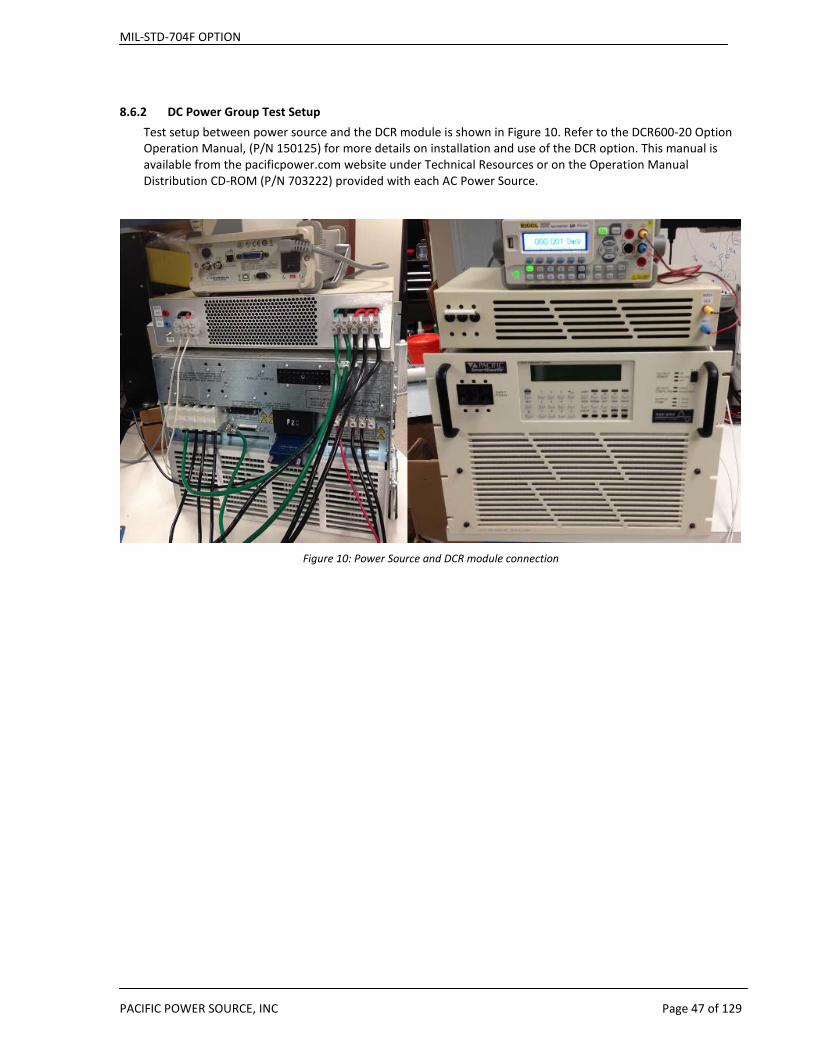
8.6.2 DC Power Group Test Setup Test setup between power source and the DCR module is shown in Figure 10. Refer to the DCR600-20 Option Operation Manual, (P/N 150125) for more details on installation and use of the DCR option. This manual is available from the pacificpower.com website under Technical Resources or on the Operation Manual Distribution CD-ROM (P/N 703222) provided with each AC Power Source.
Figure 10: Power Source and DCR module connection
MIL-STD-704F OPTION
PACIFIC POWER SOURCE, INC Page 48 of 129
9 MIL-STD-704F Test Sequence Coverage
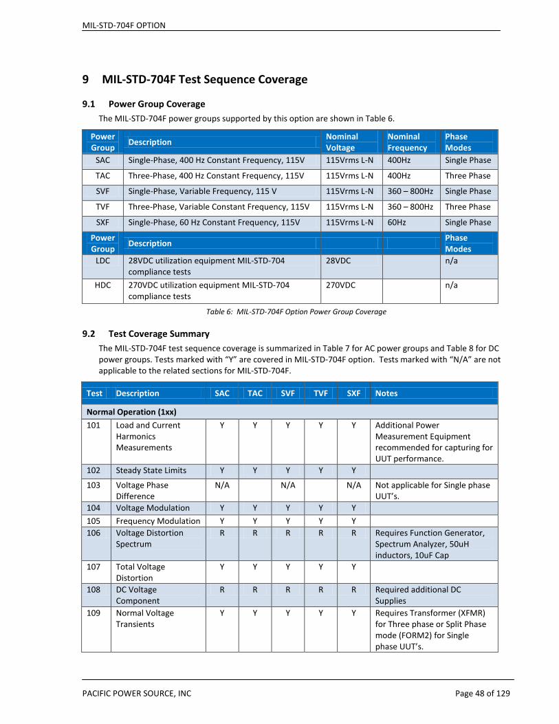
9.1 Power Group Coverage The MIL-STD-704F power groups supported by this option are shown in Table 6.
Power Group Description Nominal
Voltage Nominal Frequency
Phase Modes
SAC Single-Phase, 400 Hz Constant Frequency, 115V 115Vrms L-N 400Hz Single Phase
TAC Three-Phase, 400 Hz Constant Frequency, 115V 115Vrms L-N 400Hz Three Phase
SVF Single-Phase, Variable Frequency, 115 V 115Vrms L-N 360 – 800Hz Single Phase
TVF Three-Phase, Variable Constant Frequency, 115V 115Vrms L-N 360 – 800Hz Three Phase
SXF Single-Phase, 60 Hz Constant Frequency, 115V 115Vrms L-N 60Hz Single Phase
Power Group Description Phase
Modes LDC 28VDC utilization equipment MIL-STD-704
compliance tests 28VDC n/a
HDC 270VDC utilization equipment MIL-STD-704 compliance tests
270VDC n/a
Table 6: MIL-STD-704F Option Power Group Coverage
9.2 Test Coverage Summary The MIL-STD-704F test sequence coverage is summarized in Table 7 for AC power groups and Table 8 for DC power groups. Tests marked with “Y” are covered in MIL-STD-704F option. Tests marked with “N/A” are not applicable to the related sections for MIL-STD-704F.
Test Description SAC TAC SVF TVF SXF Notes
Normal Operation (1xx) 101 Load and Current
Harmonics Measurements
Y Y Y Y Y Additional Power Measurement Equipment recommended for capturing for UUT performance.
102 Steady State Limits Y Y Y Y Y
103 Voltage Phase Difference
N/A N/A N/A Not applicable for Single phase UUT’s.
104 Voltage Modulation Y Y Y Y Y 105 Frequency Modulation Y Y Y Y Y 106 Voltage Distortion
Spectrum R R R R R Requires Function Generator,
Spectrum Analyzer, 50uH inductors, 10uF Cap
107 Total Voltage Distortion
Y Y Y Y Y
108 DC Voltage Component
R R R R R Required additional DC Supplies
109 Normal Voltage Transients
Y Y Y Y Y Requires Transformer (XFMR) for Three phase or Split Phase mode (FORM2) for Single phase UUT’s.

MIL-STD-704F OPTION
PACIFIC POWER SOURCE, INC Page 49 of 129
Test Description SAC TAC SVF TVF SXF Notes
110 Normal Frequency Transients
Y Y Y Y Y
Transfer (2xx) 201
Power Interrupt
Y Y Y Y Y Requires Transformer (XFMR) for Three phase or Split Phase mode (FORM2) for Single phase UUT’s.
Abnormal Operation (3xx) 301 Abnormal Limits for
Voltage and Frequency
Y Y Y Y Y
302 Abnormal Voltage Transients
Y Y Y Y Y Requires Transformer (XFMR) for Three phase or Split Phase mode (FORM2) for Single phase UUT’s.
303 Abnormal Frequency Transients
Y Y Y Y Y
Emergency Operation (4xx) 401 Emergency Limits for
Voltage and Frequency
Y Y Y Y Y
Starting (5xx)
501 Not Typically Required N/A N/A N/A N/A N/A Not applicable to AC powered equipment
Power Failure (6xx) 601 Power Failure Y Y Y Y Y 602 One Phase and Two
Phase Power Failures N/A Y N/A Y N/A
603 Phase Reversal Y Y Y Y Y Table 7: MIL-STD-704F Test Coverage Summary Table – AC Power Groups
Legend: Y = Full support N/A = Not Applicable – No Test Required R = Requires Additional Equipment Z = Requires Prog-Z option on AC Source N = Not supported

MIL-STD-704F OPTION
PACIFIC POWER SOURCE, INC Page 50 of 129
Test Description LDC HDC Notes
101 Load Measurements Y Y 102 Steady State Limits for Voltage (Normal) Y Y
103 Voltage Distortion Spectrum R R Requires additional equipment 104 Total Ripple N N Test is not supported 105 Normal Voltage Transients Y Y
201 Power Interrupt Y Y 301 Steady State Limits for Voltage
(Abnormal) Y Y
302 Abnormal Voltage Transients Y Y
401 Steady State Limits for Voltage (Emergency)
Y Y
501 Starting Voltage Transients Y Y 601 Power Failure Y Y 602 Polarity Reversal Y Y
Table 8: MIL-STD-704F Test Coverage Summary Table – DC Power Groups
Legend: Y = Full support N/A = Not Applicable – No Test Required R = Requires Additional Equipment Z = Requires Prog-Z option on AC Source N = Not supported
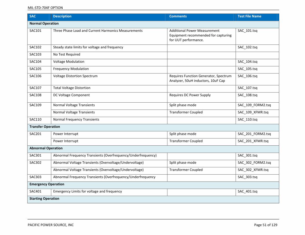
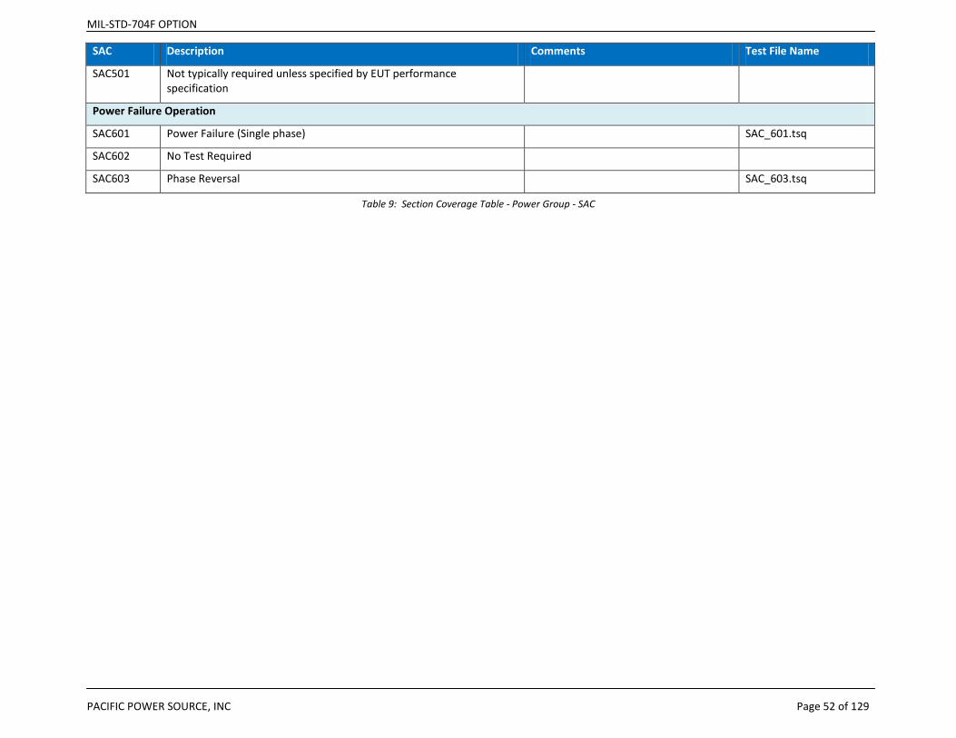
9.3 Test Sequence Files by Power Group Tables For each supported Power Group, the tables in this section show the test numbers, a short description of the test, any comments relating to this test and associated test sequence file names as provided by this option.
NOTE: Depending on the power source used to perform tests with the MIL-STD-704F option, additional equipment may be required if the test or load requirements are beyond the power source capabilities. These additional requirements are specified in the following test section coverage tables, ”Comments” column.
MIL-STD-704F OPTION
PACIFIC POWER SOURCE, INC Page 51 of 129
SAC Description Comments Test File Name
Normal Operation
SAC101 Three Phase Load and Current Harmonics Measurements Additional Power Measurement Equipment recommended for capturing for UUT performance.
SAC_101.tsq
SAC102 Steady state limits for voltage and frequency SAC_102.tsq
SAC103 No Test Required
SAC104 Voltage Modulation SAC_104.tsq
SAC105 Frequency Modulation SAC_105.tsq
SAC106 Voltage Distortion Spectrum Requires Function Generator, Spectrum Analyzer, 50uH inductors, 10uF Cap
SAC_106.tsq
SAC107 Total Voltage Distortion SAC_107.tsq
SAC108 DC Voltage Component Requires DC Power Supply SAC_108.tsq
SAC109 Normal Voltage Transients Split phase mode SAC_109_FORM2.tsq
Normal Voltage Transients Transformer Coupled SAC_109_XFMR.tsq
SAC110 Normal Frequency Transients SAC_110.tsq
Transfer Operation
SAC201 Power Interrupt Split phase mode SAC_201_FORM2.tsq
Power Interrupt Transformer Coupled SAC_201_XFMR.tsq
Abnormal Operation
SAC301 Abnormal Frequency Transients (Overfrequency/Underfrequency) SAC_301.tsq
SAC302 Abnormal Voltage Transients (Overvoltage/Undervoltage) Split phase mode SAC_302_FORM2.tsq
Abnormal Voltage Transients (Overvoltage/Undervoltage) Transformer Coupled SAC_302_XFMR.tsq
SAC303 Abnormal Frequency Transients (Overfrequency/Underfrequency SAC_303.tsq
Emergency Operation
SAC401 Emergency Limits for voltage and frequency SAC_401.tsq
Starting Operation
MIL-STD-704F OPTION
PACIFIC POWER SOURCE, INC Page 52 of 129
SAC Description Comments Test File Name
SAC501 Not typically required unless specified by EUT performance specification
Power Failure Operation
SAC601 Power Failure (Single phase) SAC_601.tsq
SAC602 No Test Required
SAC603 Phase Reversal SAC_603.tsq
Table 9: Section Coverage Table - Power Group - SAC

MIL-STD-704F OPTION
PACIFIC POWER SOURCE, INC Page 53 of 129
TAC Description Comments Test File Name
Normal Operation
TAC101 Three Phase Load and Current Harmonics Measurements Additional Power Measurement Equipment recommended for capturing for UUT performance.
TAC_101.tsq
TAC102 Steady state limits for voltage and frequency TAC_102.tsq
TAC103 No Test Required TAC_103.tsq
TAC104 Voltage Modulation TAC_104.tsq
TAC105 Frequency Modulation TAC_105.tsq
TAC106 Voltage Distortion Spectrum Requires Function Generator, Spectrum Analyzer, 50uH inductors, 10uF Cap
TAC_106.tsq
TAC107 Total Voltage Distortion TAC_107.tsq
TAC108 DC Voltage Component Requires DC Power Supply TAC_108.tsq
TAC109 Normal Voltage Transients TAC_109.tsq
TAC110 Normal Frequency Transients TAC_110.tsq
Transfer Operation
TAC201 Power Interrupt TAC_201.tsq
Abnormal Operation
TAC301 Abnormal Frequency Transients (Overfrequency/Underfrequency TAC_301.tsq
TAC302 Abnormal Voltage Transients (Overvoltage/Undervoltage) TAC_302.tsq
TAC303 Abnormal Frequency Transients (Overfrequency/Underfrequency TAC_303.tsq
Emergency Operation
TAC401 Emergency Limits for voltage and frequency TAC_401.tsq
Starting Operation
TAC501 Not typically required unless specified by EUT performance specification
Power Failure Operation
MIL-STD-704F OPTION
PACIFIC POWER SOURCE, INC Page 54 of 129
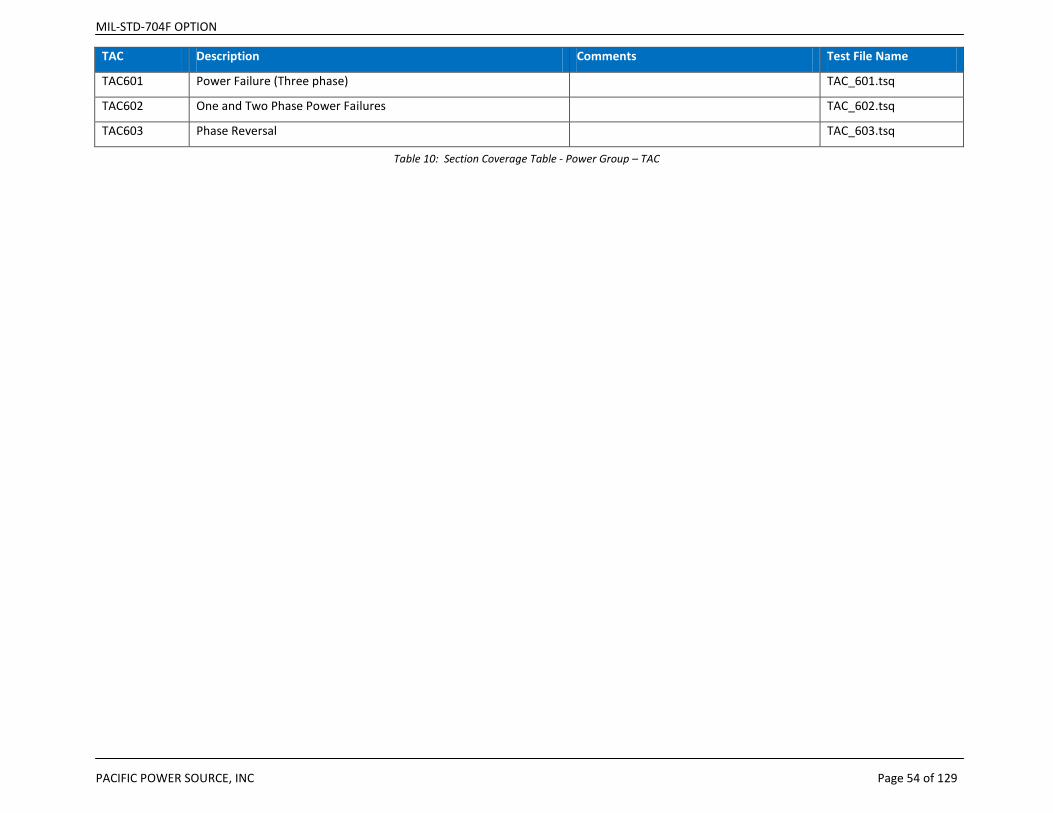
TAC Description Comments Test File Name
TAC601 Power Failure (Three phase) TAC_601.tsq
TAC602 One and Two Phase Power Failures TAC_602.tsq
TAC603 Phase Reversal TAC_603.tsq
Table 10: Section Coverage Table - Power Group – TAC
MIL-STD-704F OPTION
PACIFIC POWER SOURCE, INC Page 55 of 129
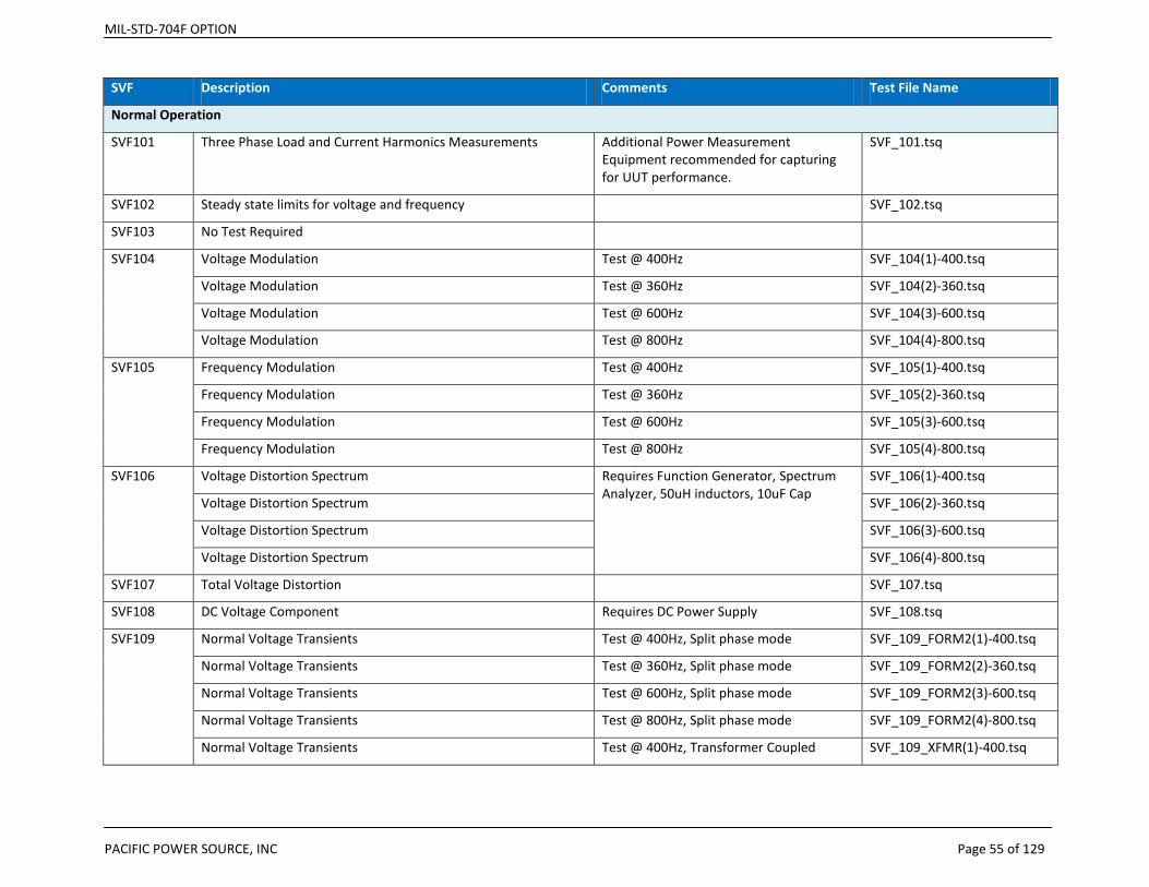
SVF Description Comments Test File Name
Normal Operation
SVF101 Three Phase Load and Current Harmonics Measurements Additional Power Measurement Equipment recommended for capturing for UUT performance.
SVF_101.tsq
SVF102 Steady state limits for voltage and frequency SVF_102.tsq
SVF103 No Test Required
SVF104 Voltage Modulation Test @ 400Hz SVF_104(1)-400.tsq
Voltage Modulation Test @ 360Hz SVF_104(2)-360.tsq
Voltage Modulation Test @ 600Hz SVF_104(3)-600.tsq
Voltage Modulation Test @ 800Hz SVF_104(4)-800.tsq
SVF105 Frequency Modulation Test @ 400Hz SVF_105(1)-400.tsq
Frequency Modulation Test @ 360Hz SVF_105(2)-360.tsq
Frequency Modulation Test @ 600Hz SVF_105(3)-600.tsq
Frequency Modulation Test @ 800Hz SVF_105(4)-800.tsq
SVF106 Voltage Distortion Spectrum Requires Function Generator, Spectrum Analyzer, 50uH inductors, 10uF Cap
SVF_106(1)-400.tsq
Voltage Distortion Spectrum SVF_106(2)-360.tsq
Voltage Distortion Spectrum SVF_106(3)-600.tsq
Voltage Distortion Spectrum SVF_106(4)-800.tsq
SVF107 Total Voltage Distortion SVF_107.tsq
SVF108 DC Voltage Component Requires DC Power Supply SVF_108.tsq
SVF109 Normal Voltage Transients Test @ 400Hz, Split phase mode SVF_109_FORM2(1)-400.tsq
Normal Voltage Transients Test @ 360Hz, Split phase mode SVF_109_FORM2(2)-360.tsq
Normal Voltage Transients Test @ 600Hz, Split phase mode SVF_109_FORM2(3)-600.tsq
Normal Voltage Transients Test @ 800Hz, Split phase mode SVF_109_FORM2(4)-800.tsq
Normal Voltage Transients Test @ 400Hz, Transformer Coupled SVF_109_XFMR(1)-400.tsq
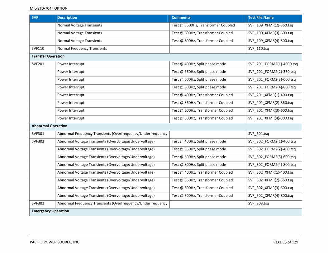
MIL-STD-704F OPTION
PACIFIC POWER SOURCE, INC Page 56 of 129
SVF Description Comments Test File Name
Normal Voltage Transients Test @ 3600Hz, Transformer Coupled SVF_109_XFMR(2)-360.tsq
Normal Voltage Transients Test @ 600Hz, Transformer Coupled SVF_109_XFMR(3)-600.tsq
Normal Voltage Transients Test @ 800Hz, Transformer Coupled SVF_109_XFMR(4)-800.tsq
SVF110 Normal Frequency Transients SVF_110.tsq
Transfer Operation
SVF201 Power Interrupt Test @ 400Hz, Split phase mode SVF_201_FORM2(1)-4000.tsq
Power Interrupt Test @ 360Hz, Split phase mode SVF_201_FORM2(2)-360.tsq
Power Interrupt Test @ 600Hz, Split phase mode SVF_201_FORM2(3)-600.tsq
Power Interrupt Test @ 800Hz, Split phase mode SVF_201_FORM2(4)-800.tsq
Power Interrupt Test @ 400Hz, Transformer Coupled SVF_201_XFMR(1)-400.tsq
Power Interrupt Test @ 360Hz, Transformer Coupled SVF_201_XFMR(2)-360.tsq
Power Interrupt Test @ 600Hz, Transformer Coupled SVF_201_XFMR(3)-600.tsq
Power Interrupt Test @ 800Hz, Transformer Coupled SVF_201_XFMR(4)-800.tsq
Abnormal Operation
SVF301 Abnormal Frequency Transients (Overfrequency/Underfrequency SVF_301.tsq
SVF302 Abnormal Voltage Transients (Overvoltage/Undervoltage) Test @ 400Hz, Split phase mode SVF_302_FORM2(1)-400.tsq
Abnormal Voltage Transients (Overvoltage/Undervoltage) Test @ 360Hz, Split phase mode SVF_302_FORM2(2)-400.tsq
Abnormal Voltage Transients (Overvoltage/Undervoltage) Test @ 600Hz, Split phase mode SVF_302_FORM2(3)-600.tsq
Abnormal Voltage Transients (Overvoltage/Undervoltage) Test @ 800Hz, Split phase mode SVF_302_FORM2(4)-800.tsq
Abnormal Voltage Transients (Overvoltage/Undervoltage) Test @ 400Hz, Transformer Coupled SVF_302_XFMR(1)-400.tsq
Abnormal Voltage Transients (Overvoltage/Undervoltage) Test @ 360Hz, Transformer Coupled SVF_302_XFMR(2)-360.tsq
Abnormal Voltage Transients (Overvoltage/Undervoltage) Test @ 600Hz, Transformer Coupled SVF_302_XFMR(3)-600.tsq
Abnormal Voltage Transients (Overvoltage/Undervoltage) Test @ 800Hz, Transformer Coupled SVF_302_XFMR(4)-800.tsq
SVF303 Abnormal Frequency Transients (Overfrequency/Underfrequency SVF_303.tsq
Emergency Operation
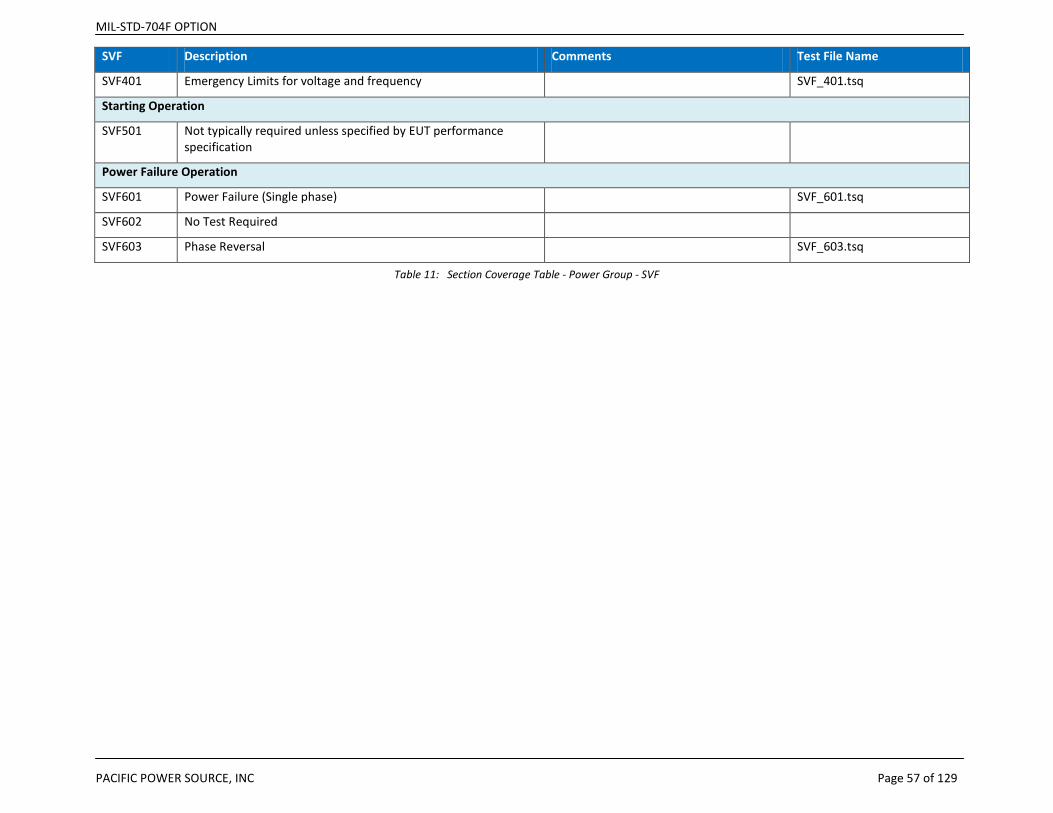
MIL-STD-704F OPTION
PACIFIC POWER SOURCE, INC Page 57 of 129
SVF Description Comments Test File Name
SVF401 Emergency Limits for voltage and frequency SVF_401.tsq
Starting Operation
SVF501 Not typically required unless specified by EUT performance specification
Power Failure Operation
SVF601 Power Failure (Single phase) SVF_601.tsq
SVF602 No Test Required
SVF603 Phase Reversal SVF_603.tsq
Table 11: Section Coverage Table - Power Group - SVF
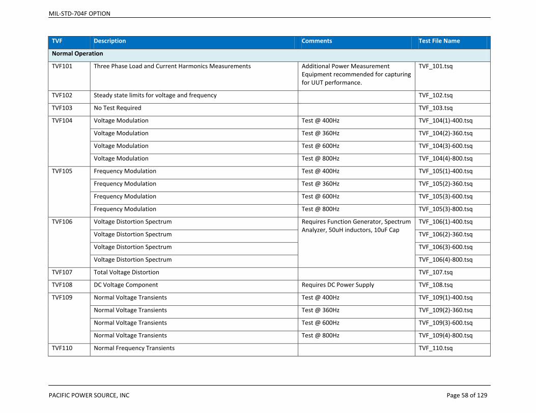
MIL-STD-704F OPTION
PACIFIC POWER SOURCE, INC Page 58 of 129
TVF Description Comments Test File Name
Normal Operation
TVF101 Three Phase Load and Current Harmonics Measurements Additional Power Measurement Equipment recommended for capturing for UUT performance.
TVF_101.tsq
TVF102 Steady state limits for voltage and frequency TVF_102.tsq
TVF103 No Test Required TVF_103.tsq
TVF104 Voltage Modulation Test @ 400Hz TVF_104(1)-400.tsq
Voltage Modulation Test @ 360Hz TVF_104(2)-360.tsq
Voltage Modulation Test @ 600Hz TVF_104(3)-600.tsq
Voltage Modulation Test @ 800Hz TVF_104(4)-800.tsq
TVF105 Frequency Modulation Test @ 400Hz TVF_105(1)-400.tsq
Frequency Modulation Test @ 360Hz TVF_105(2)-360.tsq
Frequency Modulation Test @ 600Hz TVF_105(3)-600.tsq
Frequency Modulation Test @ 800Hz TVF_105(3)-800.tsq
TVF106 Voltage Distortion Spectrum Requires Function Generator, Spectrum Analyzer, 50uH inductors, 10uF Cap
TVF_106(1)-400.tsq
Voltage Distortion Spectrum TVF_106(2)-360.tsq
Voltage Distortion Spectrum TVF_106(3)-600.tsq
Voltage Distortion Spectrum TVF_106(4)-800.tsq
TVF107 Total Voltage Distortion TVF_107.tsq
TVF108 DC Voltage Component Requires DC Power Supply TVF_108.tsq
TVF109 Normal Voltage Transients Test @ 400Hz TVF_109(1)-400.tsq
Normal Voltage Transients Test @ 360Hz TVF_109(2)-360.tsq
Normal Voltage Transients Test @ 600Hz TVF_109(3)-600.tsq
Normal Voltage Transients Test @ 800Hz TVF_109(4)-800.tsq
TVF110 Normal Frequency Transients TVF_110.tsq
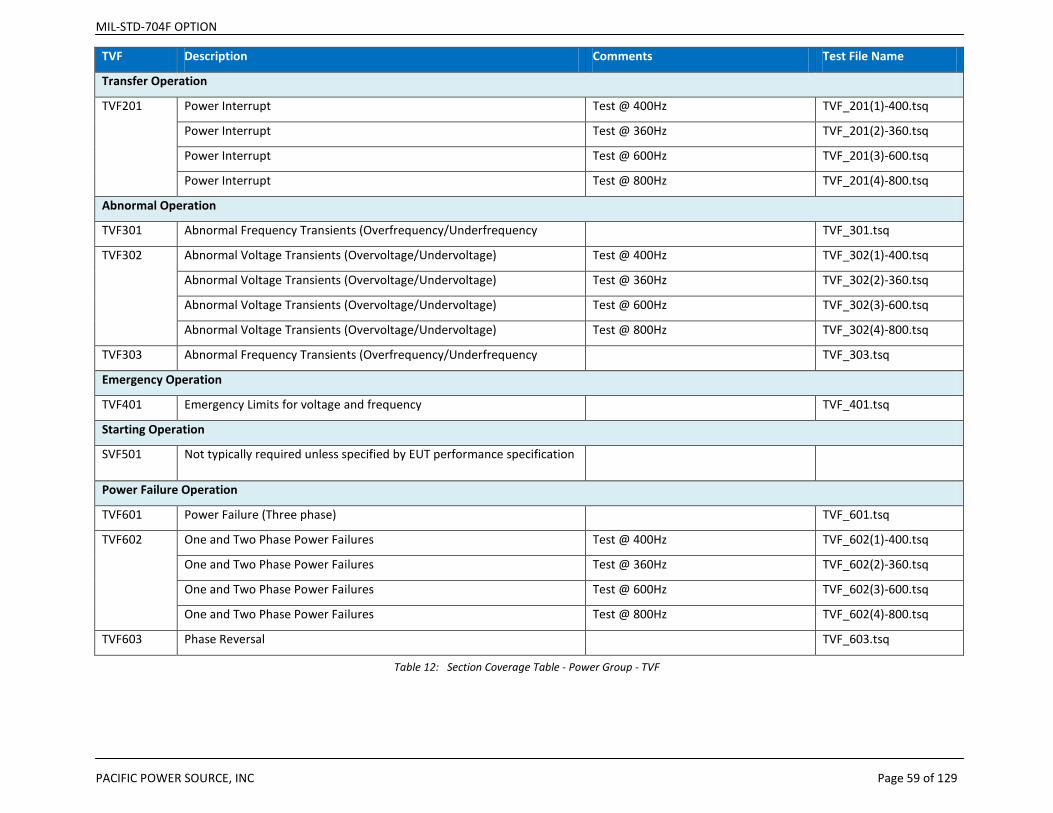
MIL-STD-704F OPTION
PACIFIC POWER SOURCE, INC Page 59 of 129
TVF Description Comments Test File Name
Transfer Operation
TVF201 Power Interrupt Test @ 400Hz TVF_201(1)-400.tsq
Power Interrupt Test @ 360Hz TVF_201(2)-360.tsq
Power Interrupt Test @ 600Hz TVF_201(3)-600.tsq
Power Interrupt Test @ 800Hz TVF_201(4)-800.tsq
Abnormal Operation
TVF301 Abnormal Frequency Transients (Overfrequency/Underfrequency TVF_301.tsq
TVF302 Abnormal Voltage Transients (Overvoltage/Undervoltage) Test @ 400Hz TVF_302(1)-400.tsq
Abnormal Voltage Transients (Overvoltage/Undervoltage) Test @ 360Hz TVF_302(2)-360.tsq
Abnormal Voltage Transients (Overvoltage/Undervoltage) Test @ 600Hz TVF_302(3)-600.tsq
Abnormal Voltage Transients (Overvoltage/Undervoltage) Test @ 800Hz TVF_302(4)-800.tsq
TVF303 Abnormal Frequency Transients (Overfrequency/Underfrequency TVF_303.tsq
Emergency Operation
TVF401 Emergency Limits for voltage and frequency TVF_401.tsq
Starting Operation
SVF501 Not typically required unless specified by EUT performance specification
Power Failure Operation
TVF601 Power Failure (Three phase) TVF_601.tsq
TVF602 One and Two Phase Power Failures Test @ 400Hz TVF_602(1)-400.tsq
One and Two Phase Power Failures Test @ 360Hz TVF_602(2)-360.tsq
One and Two Phase Power Failures Test @ 600Hz TVF_602(3)-600.tsq
One and Two Phase Power Failures Test @ 800Hz TVF_602(4)-800.tsq
TVF603 Phase Reversal TVF_603.tsq
Table 12: Section Coverage Table - Power Group - TVF

MIL-STD-704F OPTION
PACIFIC POWER SOURCE, INC Page 60 of 129
SXF Description Comments Test File Name
Normal Operation
SXF101 Three Phase Load and Current Harmonics Measurements
Additional Power Measurement Equipment recommended for capturing for UUT performance.
SXF_101.tsq
SXF102 Steady state limits for voltage and frequency SXF_102.tsq
SXF103 No Test Required SXF_103.tsq
SXF104 Voltage Modulation SXF_104.tsq
SXF105 Frequency Modulation SXF_105.tsq
SXF106 Voltage Distortion Spectrum Requires Function Generator, Spectrum Analyzer, 50uH inductors, 10uF Cap
SXF_106.tsq
SXF107 Total Voltage Distortion SXF_107.tsq
SXF108 DC Voltage Component Requires DC Power Supply SXF_108.tsq
SXF109 Normal Voltage Transients Split phase mode SXF_109_FORM2.tsq
Normal Voltage Transients Transformer Coupled SXF_109_XFMR.tsq
SXF110 Normal Frequency Transients SXF_110.tsq
Transfer Operation
Power Interrupt SXF_201.tsq
Abnormal Operation
SXF301 Abnormal Frequency Transients (Overfrequency/Underfrequency
SXF_301.tsq
SXF302 Abnormal Voltage Transients (Overvoltage/Undervoltage)
Split phase mode SXF_302_FORM2.tsq
Abnormal Voltage Transients (Overvoltage/Undervoltage)
Transformer Coupled SXF_302_XFMR.tsq
SXF303 Abnormal Frequency Transients (Overfrequency/Underfrequency
SXF_303.tsq
Emergency Operation

MIL-STD-704F OPTION
PACIFIC POWER SOURCE, INC Page 61 of 129
SXF Description Comments Test File Name
SXF401 Emergency Limits for voltage and frequency SXF_401.tsq
Starting Operation
SXF501 Not typically required unless specified by EUT performance specification
SXF_501.tsq
Power Failure Operation
SXF601 Power Failure (Single phase) SXF_601.tsq
SXF602 No Test Required SXF_602.tsq
SXF603 Phase Reversal SXF_603.tsq
Table 13: Section Coverage Table - Power Group – SXF
LDC Description Comments Test File Name
LDC101 Load Measurements LDC_101.tsq
LDC102 Steady State Limits for Voltage (Normal) LDC_102.tsq
LDC103 Voltage Distortion Spectrum Requires additional equipment LDC_103.tsq
LDC104 Total Ripples This test is not supported by DCR
LDC105 Normal Voltage Transients LDC_105.tsq
LDC201 Power Interrupt LDC_201.tsq
LDC301 Steady State Limits for Voltage (Abnormal) LDC_301.tsq
LDC302 Abnormal Voltage Transients LDC_302.tsq
LDC401 Steady State Limits for Voltage (Emergency) LDC_401.tsq
LDC501 Starting Voltage Transients LDC_501.tsq
LDC601 Power Failure LDC_601.tsq
LDC602 Polarity Reversal LDC_602.tsq
Table 14: Section Coverage Table – LDC-28VDC
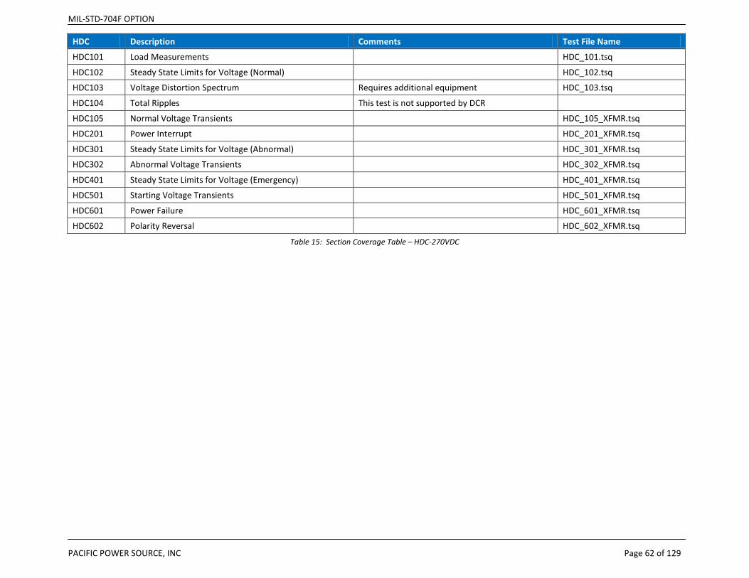
MIL-STD-704F OPTION
PACIFIC POWER SOURCE, INC Page 62 of 129
HDC Description Comments Test File Name
HDC101 Load Measurements HDC_101.tsq
HDC102 Steady State Limits for Voltage (Normal) HDC_102.tsq
HDC103 Voltage Distortion Spectrum Requires additional equipment HDC_103.tsq
HDC104 Total Ripples This test is not supported by DCR
HDC105 Normal Voltage Transients HDC_105_XFMR.tsq
HDC201 Power Interrupt HDC_201_XFMR.tsq
HDC301 Steady State Limits for Voltage (Abnormal) HDC_301_XFMR.tsq
HDC302 Abnormal Voltage Transients HDC_302_XFMR.tsq
HDC401 Steady State Limits for Voltage (Emergency) HDC_401_XFMR.tsq
HDC501 Starting Voltage Transients HDC_501_XFMR.tsq
HDC601 Power Failure HDC_601_XFMR.tsq
HDC602 Polarity Reversal HDC_602_XFMR.tsq
Table 15: Section Coverage Table – HDC-270VDC
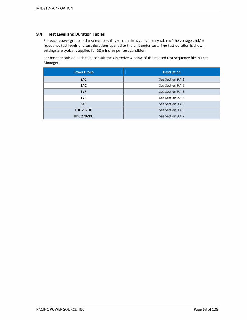
MIL-STD-704F OPTION
PACIFIC POWER SOURCE, INC Page 63 of 129
9.4 Test Level and Duration Tables For each power group and test number, this section shows a summary table of the voltage and/or frequency test levels and test durations applied to the unit under test. If no test duration is shown, settings are typically applied for 30 minutes per test condition.
For more details on each test, consult the Objective window of the related test sequence file in Test Manager.
Power Group Description
SAC See Section 9.4.1
TAC See Section 9.4.2
SVF See Section 9.4.3
TVF See Section 9.4.4
SXF See Section 9.4.5
LDC 28VDC See Section 9.4.6
HDC 270VDC See Section 9.4.7
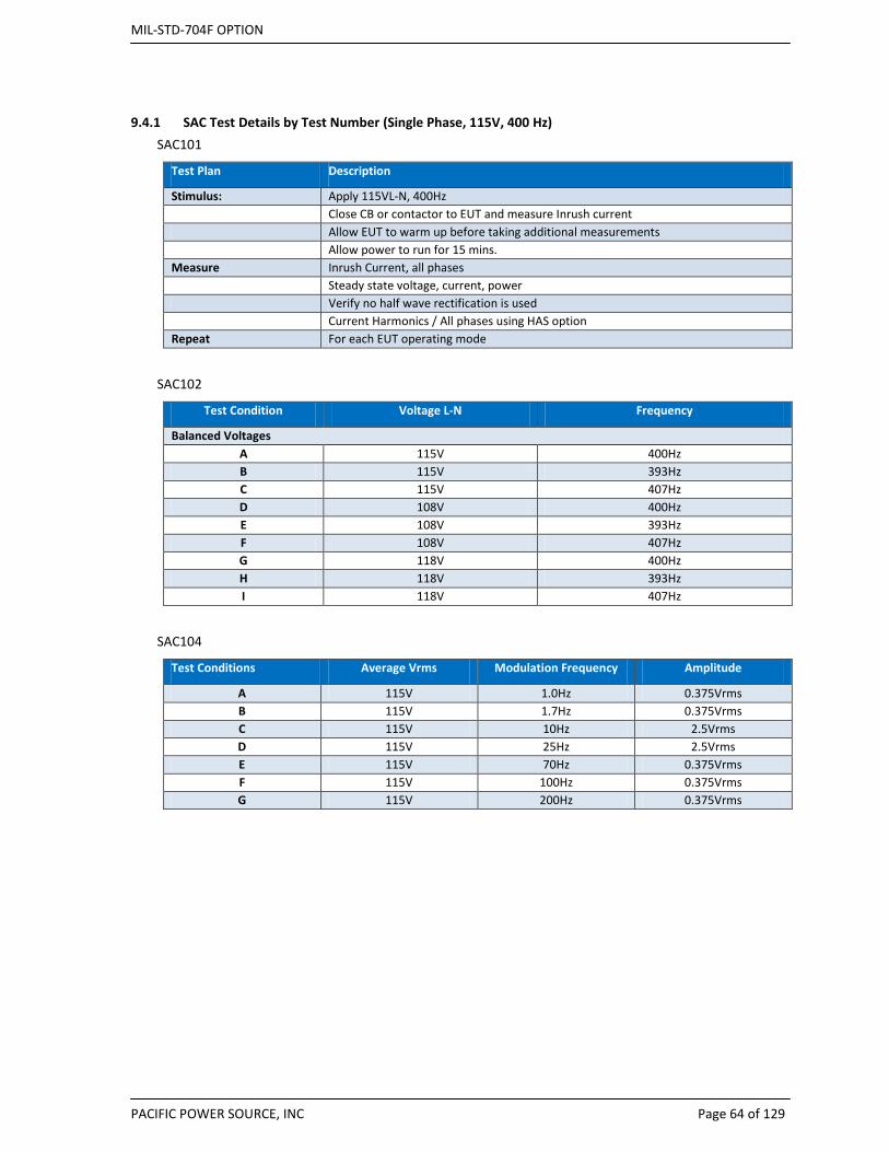
MIL-STD-704F OPTION
PACIFIC POWER SOURCE, INC Page 64 of 129
9.4.1 SAC Test Details by Test Number (Single Phase, 115V, 400 Hz) SAC101
Test Plan Description
Stimulus: Apply 115VL-N, 400Hz Close CB or contactor to EUT and measure Inrush current Allow EUT to warm up before taking additional measurements Allow power to run for 15 mins. Measure Inrush Current, all phases Steady state voltage, current, power Verify no half wave rectification is used Current Harmonics / All phases using HAS option Repeat For each EUT operating mode
SAC102
Test Condition Voltage L-N Frequency
Balanced Voltages A 115V 400Hz B 115V 393Hz C 115V 407Hz D 108V 400Hz E 108V 393Hz F 108V 407Hz G 118V 400Hz H 118V 393Hz I 118V 407Hz
SAC104
Test Conditions Average Vrms Modulation Frequency Amplitude
A 115V 1.0Hz 0.375Vrms B 115V 1.7Hz 0.375Vrms C 115V 10Hz 2.5Vrms D 115V 25Hz 2.5Vrms E 115V 70Hz 0.375Vrms F 115V 100Hz 0.375Vrms G 115V 200Hz 0.375Vrms
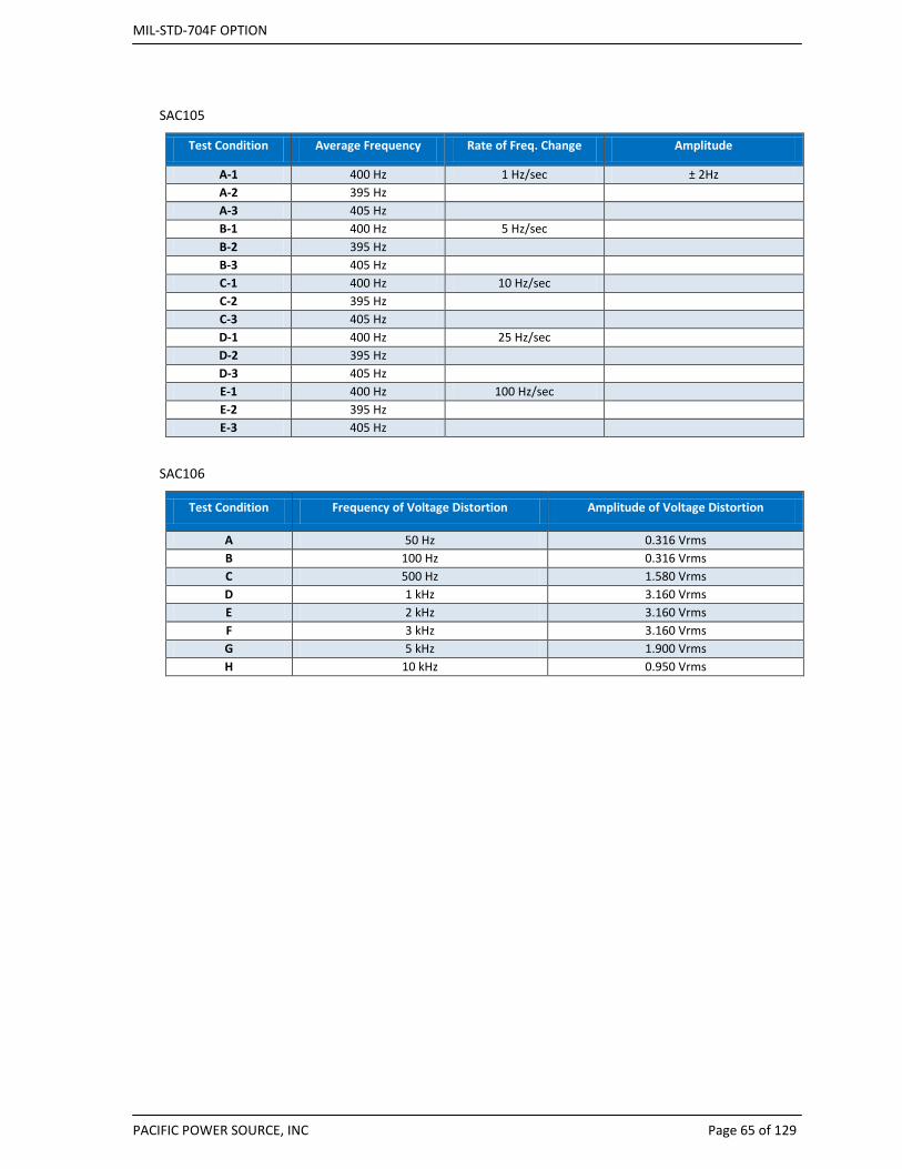
MIL-STD-704F OPTION
PACIFIC POWER SOURCE, INC Page 65 of 129
SAC105
Test Condition Average Frequency Rate of Freq. Change Amplitude
A-1 400 Hz 1 Hz/sec ± 2Hz A-2 395 Hz
A-3 405 Hz
B-1 400 Hz 5 Hz/sec
B-2 395 Hz
B-3 405 Hz
C-1 400 Hz 10 Hz/sec
C-2 395 Hz
C-3 405 Hz
D-1 400 Hz 25 Hz/sec
D-2 395 Hz
D-3 405 Hz
E-1 400 Hz 100 Hz/sec
E-2 395 Hz
E-3 405 Hz
SAC106
Test Condition Frequency of Voltage Distortion Amplitude of Voltage Distortion
A 50 Hz 0.316 Vrms B 100 Hz 0.316 Vrms C 500 Hz 1.580 Vrms D 1 kHz 3.160 Vrms E 2 kHz 3.160 Vrms F 3 kHz 3.160 Vrms G 5 kHz 1.900 Vrms H 10 kHz 0.950 Vrms

MIL-STD-704F OPTION
PACIFIC POWER SOURCE, INC Page 66 of 129
SAC107
Harmonic MIL-STD-704 Rev B - F Percent of Fund.
Fundamental 100% 2nd 0% 3rd 2.75% 4th 0% 5th 2.75% 6th 0% 7th 1.97% 8th 0% 9th 1.53%
10th 0% 11th 1.25% 12th 0% 13th 1.06% 14th 0% 15th 0.92%
SAC108
Test Condition Direct Current Component of AC Voltage
A + 0.10V B - 0.10 V
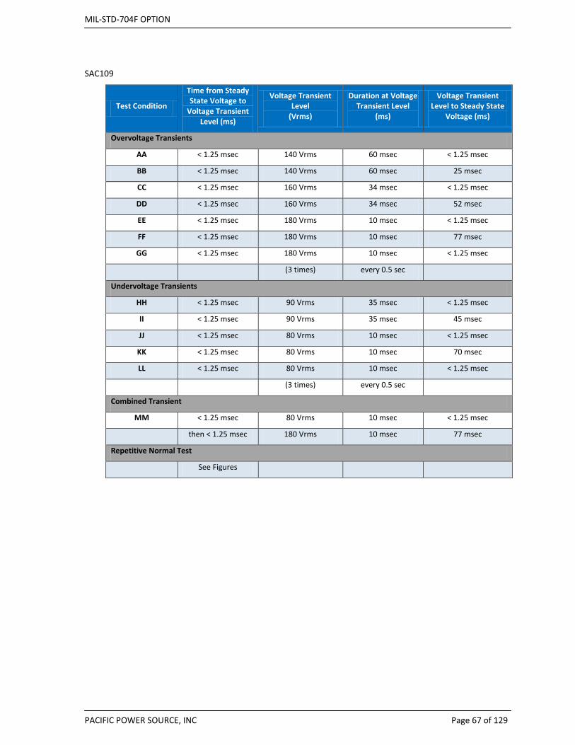
MIL-STD-704F OPTION
PACIFIC POWER SOURCE, INC Page 67 of 129
SAC109
Test Condition
Time from Steady State Voltage to
Voltage Transient Level (ms)
Voltage Transient Level
(Vrms)
Duration at Voltage Transient Level
(ms)
Voltage Transient Level to Steady State
Voltage (ms)
Overvoltage Transients
AA < 1.25 msec 140 Vrms 60 msec < 1.25 msec
BB < 1.25 msec 140 Vrms 60 msec 25 msec
CC < 1.25 msec 160 Vrms 34 msec < 1.25 msec
DD < 1.25 msec 160 Vrms 34 msec 52 msec
EE < 1.25 msec 180 Vrms 10 msec < 1.25 msec
FF < 1.25 msec 180 Vrms 10 msec 77 msec
GG < 1.25 msec 180 Vrms 10 msec < 1.25 msec
(3 times) every 0.5 sec
Undervoltage Transients
HH < 1.25 msec 90 Vrms 35 msec < 1.25 msec
II < 1.25 msec 90 Vrms 35 msec 45 msec
JJ < 1.25 msec 80 Vrms 10 msec < 1.25 msec
KK < 1.25 msec 80 Vrms 10 msec 70 msec
LL < 1.25 msec 80 Vrms 10 msec < 1.25 msec
(3 times) every 0.5 sec
Combined Transient
MM < 1.25 msec 80 Vrms 10 msec < 1.25 msec
then < 1.25 msec 180 Vrms 10 msec 77 msec
Repetitive Normal Test
See Figures

MIL-STD-704F OPTION
PACIFIC POWER SOURCE, INC Page 68 of 129
Figure 11: Voltage Transition Pulse Details
Figure 12: Repetitive Voltage transients.
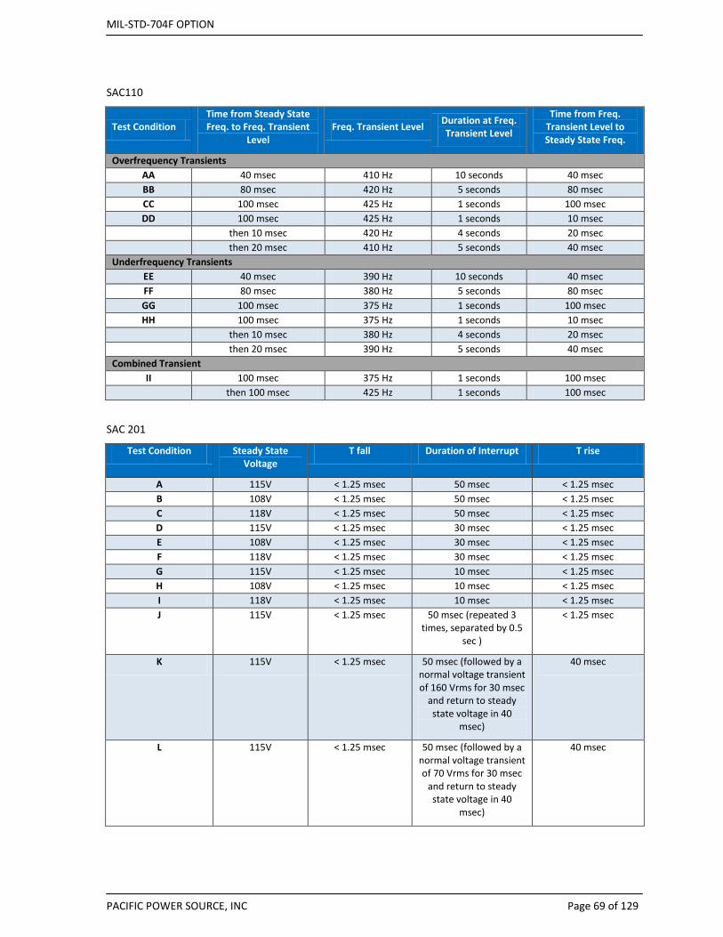
MIL-STD-704F OPTION
PACIFIC POWER SOURCE, INC Page 69 of 129
SAC110
Test Condition Time from Steady State Freq. to Freq. Transient
Level Freq. Transient Level Duration at Freq.
Transient Level
Time from Freq. Transient Level to Steady State Freq.
Overfrequency Transients AA 40 msec 410 Hz 10 seconds 40 msec BB 80 msec 420 Hz 5 seconds 80 msec CC 100 msec 425 Hz 1 seconds 100 msec DD 100 msec 425 Hz 1 seconds 10 msec
then 10 msec 420 Hz 4 seconds 20 msec then 20 msec 410 Hz 5 seconds 40 msec Underfrequency Transients
EE 40 msec 390 Hz 10 seconds 40 msec FF 80 msec 380 Hz 5 seconds 80 msec GG 100 msec 375 Hz 1 seconds 100 msec HH 100 msec 375 Hz 1 seconds 10 msec
then 10 msec 380 Hz 4 seconds 20 msec then 20 msec 390 Hz 5 seconds 40 msec Combined Transient
II 100 msec 375 Hz 1 seconds 100 msec
then 100 msec 425 Hz 1 seconds 100 msec
SAC 201
Test Condition Steady State Voltage
T fall Duration of Interrupt T rise
A 115V < 1.25 msec 50 msec < 1.25 msec B 108V < 1.25 msec 50 msec < 1.25 msec C 118V < 1.25 msec 50 msec < 1.25 msec D 115V < 1.25 msec 30 msec < 1.25 msec E 108V < 1.25 msec 30 msec < 1.25 msec F 118V < 1.25 msec 30 msec < 1.25 msec G 115V < 1.25 msec 10 msec < 1.25 msec H 108V < 1.25 msec 10 msec < 1.25 msec I 118V < 1.25 msec 10 msec < 1.25 msec J 115V < 1.25 msec 50 msec (repeated 3
times, separated by 0.5 sec )
< 1.25 msec
K 115V < 1.25 msec 50 msec (followed by a normal voltage transient of 160 Vrms for 30 msec
and return to steady state voltage in 40
msec)
40 msec
L 115V < 1.25 msec 50 msec (followed by a normal voltage transient of 70 Vrms for 30 msec
and return to steady state voltage in 40
msec)
40 msec

MIL-STD-704F OPTION
PACIFIC POWER SOURCE, INC Page 70 of 129
SAC301
Test Condition Voltage Frequency
Abnormal Limit 704F
A 115 380
Voltage 100 V
B 115 420
ALSS C 100 400
Voltage 125 V
D 100 380
AHSS E 100 420
Frequency 380 Hz
F 125 400
ALSS
G 125 380
Frequency 420 Hz
H 125 420
AHSS
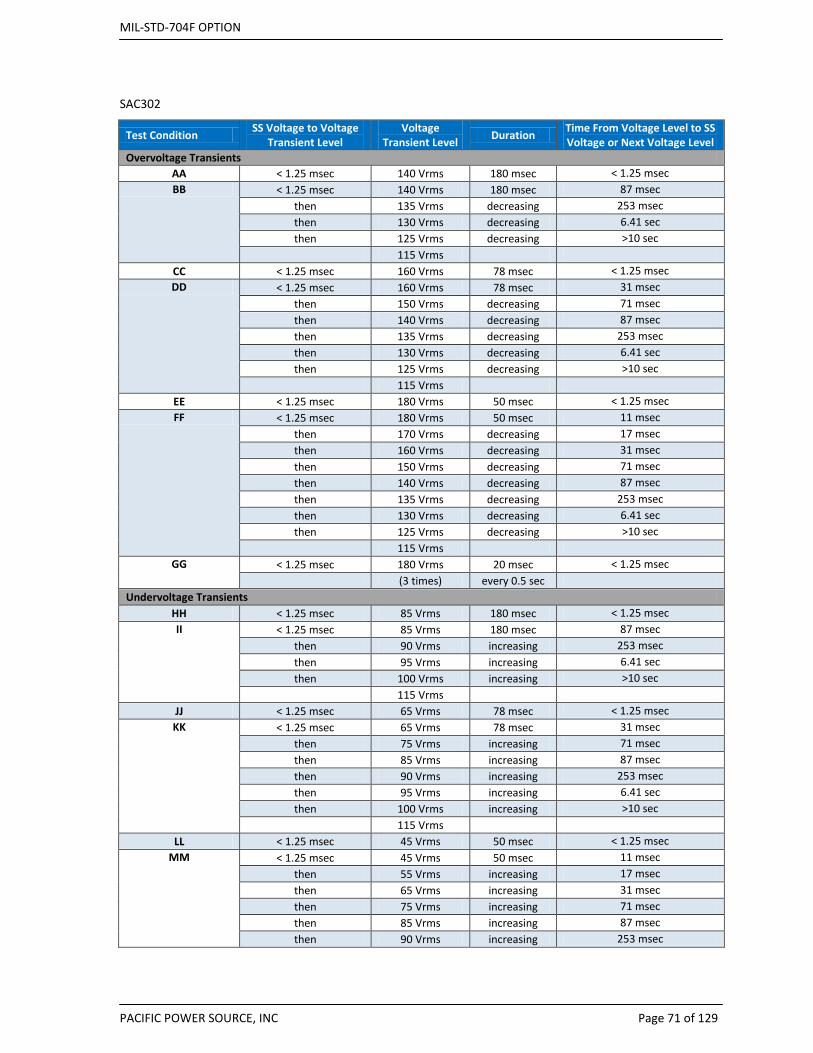
MIL-STD-704F OPTION
PACIFIC POWER SOURCE, INC Page 71 of 129
SAC302
Test Condition SS Voltage to Voltage Transient Level
Voltage Transient Level Duration Time From Voltage Level to SS
Voltage or Next Voltage Level Overvoltage Transients
AA < 1.25 msec 140 Vrms 180 msec < 1.25 msec BB < 1.25 msec 140 Vrms 180 msec 87 msec
then 135 Vrms decreasing 253 msec then 130 Vrms decreasing 6.41 sec then 125 Vrms decreasing >10 sec
115 Vrms CC < 1.25 msec 160 Vrms 78 msec < 1.25 msec DD < 1.25 msec 160 Vrms 78 msec 31 msec
then 150 Vrms decreasing 71 msec then 140 Vrms decreasing 87 msec then 135 Vrms decreasing 253 msec then 130 Vrms decreasing 6.41 sec then 125 Vrms decreasing >10 sec
115 Vrms EE < 1.25 msec 180 Vrms 50 msec < 1.25 msec FF < 1.25 msec 180 Vrms 50 msec 11 msec
then 170 Vrms decreasing 17 msec then 160 Vrms decreasing 31 msec then 150 Vrms decreasing 71 msec then 140 Vrms decreasing 87 msec then 135 Vrms decreasing 253 msec then 130 Vrms decreasing 6.41 sec then 125 Vrms decreasing >10 sec
115 Vrms GG < 1.25 msec 180 Vrms 20 msec < 1.25 msec
(3 times) every 0.5 sec Undervoltage Transients
HH < 1.25 msec 85 Vrms 180 msec < 1.25 msec II < 1.25 msec 85 Vrms 180 msec 87 msec
then 90 Vrms increasing 253 msec then 95 Vrms increasing 6.41 sec then 100 Vrms increasing >10 sec
115 Vrms JJ < 1.25 msec 65 Vrms 78 msec < 1.25 msec KK < 1.25 msec 65 Vrms 78 msec 31 msec
then 75 Vrms increasing 71 msec then 85 Vrms increasing 87 msec then 90 Vrms increasing 253 msec then 95 Vrms increasing 6.41 sec then 100 Vrms increasing >10 sec
115 Vrms LL < 1.25 msec 45 Vrms 50 msec < 1.25 msec
MM < 1.25 msec 45 Vrms 50 msec 11 msec then 55 Vrms increasing 17 msec then 65 Vrms increasing 31 msec then 75 Vrms increasing 71 msec then 85 Vrms increasing 87 msec then 90 Vrms increasing 253 msec
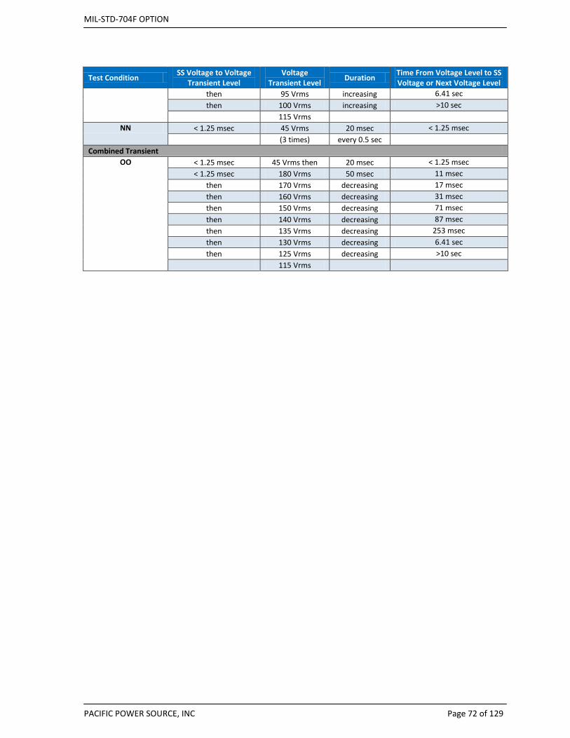
MIL-STD-704F OPTION
PACIFIC POWER SOURCE, INC Page 72 of 129
Test Condition SS Voltage to Voltage Transient Level
Voltage Transient Level Duration Time From Voltage Level to SS
Voltage or Next Voltage Level then 95 Vrms increasing 6.41 sec then 100 Vrms increasing >10 sec
115 Vrms NN < 1.25 msec 45 Vrms 20 msec < 1.25 msec
(3 times) every 0.5 sec Combined Transient
OO
< 1.25 msec 45 Vrms then 20 msec < 1.25 msec < 1.25 msec 180 Vrms 50 msec 11 msec
then 170 Vrms decreasing 17 msec then 160 Vrms decreasing 31 msec then 150 Vrms decreasing 71 msec then 140 Vrms decreasing 87 msec then 135 Vrms decreasing 253 msec then 130 Vrms decreasing 6.41 sec then 125 Vrms decreasing >10 sec
115 Vrms

MIL-STD-704F OPTION
PACIFIC POWER SOURCE, INC Page 73 of 129
SAC303
Test Condition Transition Time Transient Level Duration Transition2
Overfrequency Transients AA 160 msec 480 Hz ½ cycle 160 msec
BB 160 msec 480 Hz 4.78 secs 160 msec
Underfrequency Transients CC 160 msec 320 Hz ½ cycle 160 msec
DD 160 msec 320 Hz 4.78 secs 160 msec
Combined Transient EE 160 msec 320 Hz then ½ cycle 160 msec
160 msec 480 Hz ½ cycle 160 msec
SAC401
Test Condition Voltage Frequency
Abnormal Limit 704F
A 115 393
Voltage 108V
B 115 407
ELSS
C 108 400
Voltage 118V
D 108 393
EHSS
E 108 407
Frequency 393Hz
F 118 400
ELSS
G 118 393
Frequency 407Hz
H 118 407
EHSS
SAC601
Test Condition Duration of Power Failure
A 100 msec
B 500 msec
C 3 secs
D 7 secs
SAC603
Test Condition Phases Duration
Physical Means Prevention Verify/Check If Not: Reversed Phase Rotation N-A 30 mins
Correct Phase Rotation A-N 30 mins
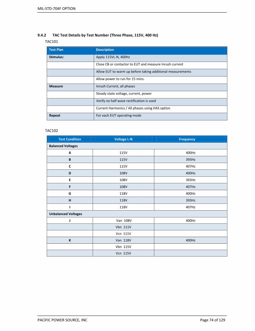
MIL-STD-704F OPTION
PACIFIC POWER SOURCE, INC Page 74 of 129
9.4.2 TAC Test Details by Test Number (Three Phase, 115V, 400 Hz) TAC101
Test Plan Description
Stimulus: Apply 115VL-N, 400Hz
Close CB or contactor to EUT and measure Inrush current
Allow EUT to warm up before taking additional measurements
Allow power to run for 15 mins.
Measure Inrush Current, all phases
Steady state voltage, current, power
Verify no half wave rectification is used
Current Harmonics / All phases using HAS option
Repeat For each EUT operating mode
TAC102
Test Condition Voltage L-N Frequency
Balanced Voltages
A 115V 400Hz
B 115V 393Hz
C 115V 407Hz
D 108V 400Hz
E 108V 393Hz
F 108V 407Hz
G 118V 400Hz
H 118V 393Hz
I 118V 407Hz
Unbalanced Voltages
J Van 108V 400Hz
Vbn 111V
Vcn 111V
K Van 118V 400Hz
Vbn 115V
Vcn 115V
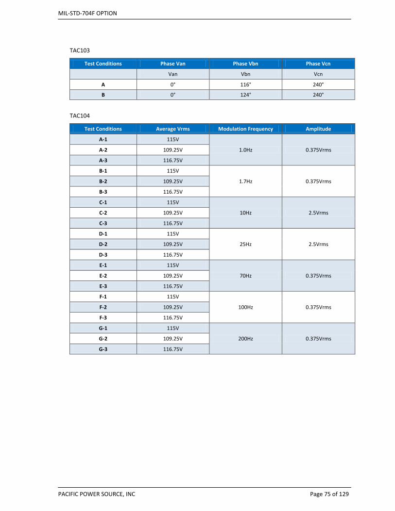
MIL-STD-704F OPTION
PACIFIC POWER SOURCE, INC Page 75 of 129
TAC103
Test Conditions Phase Van Phase Vbn Phase Vcn
Van Vbn Vcn
A 0° 116° 240°
B 0° 124° 240°
TAC104
Test Conditions Average Vrms Modulation Frequency Amplitude
A-1 115V
1.0Hz 0.375Vrms A-2 109.25V
A-3 116.75V
B-1 115V
1.7Hz 0.375Vrms B-2 109.25V
B-3 116.75V
C-1 115V
10Hz 2.5Vrms C-2 109.25V
C-3 116.75V
D-1 115V
25Hz 2.5Vrms D-2 109.25V
D-3 116.75V
E-1 115V
70Hz 0.375Vrms E-2 109.25V
E-3 116.75V
F-1 115V
100Hz 0.375Vrms F-2 109.25V
F-3 116.75V
G-1 115V
200Hz 0.375Vrms G-2 109.25V
G-3 116.75V
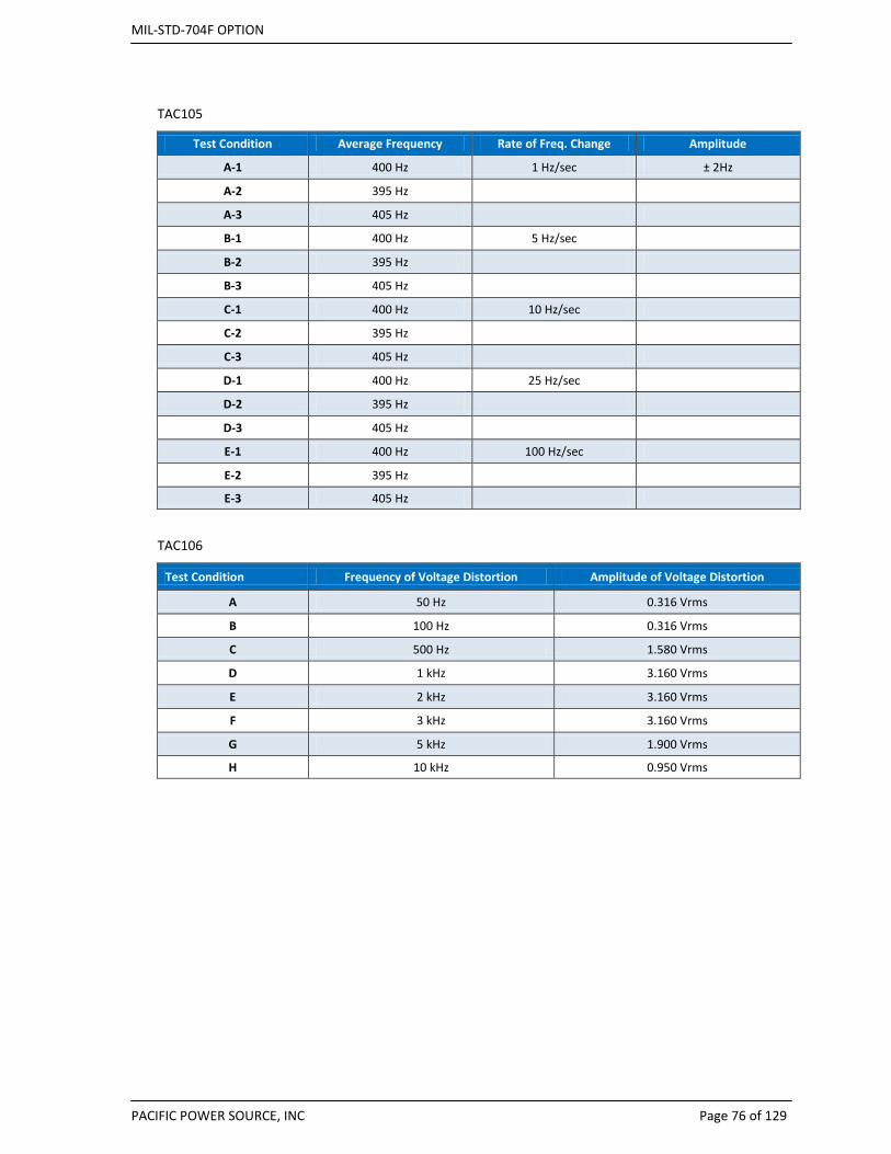
MIL-STD-704F OPTION
PACIFIC POWER SOURCE, INC Page 76 of 129
TAC105
Test Condition Average Frequency Rate of Freq. Change Amplitude
A-1 400 Hz 1 Hz/sec ± 2Hz
A-2 395 Hz
A-3 405 Hz
B-1 400 Hz 5 Hz/sec
B-2 395 Hz
B-3 405 Hz
C-1 400 Hz 10 Hz/sec
C-2 395 Hz
C-3 405 Hz
D-1 400 Hz 25 Hz/sec
D-2 395 Hz
D-3 405 Hz
E-1 400 Hz 100 Hz/sec
E-2 395 Hz
E-3 405 Hz
TAC106
Test Condition Frequency of Voltage Distortion Amplitude of Voltage Distortion
A 50 Hz 0.316 Vrms
B 100 Hz 0.316 Vrms
C 500 Hz 1.580 Vrms
D 1 kHz 3.160 Vrms
E 2 kHz 3.160 Vrms
F 3 kHz 3.160 Vrms
G 5 kHz 1.900 Vrms
H 10 kHz 0.950 Vrms

MIL-STD-704F OPTION
PACIFIC POWER SOURCE, INC Page 77 of 129
TAC107
Harmonic MIL-STD-704 Rev B - F Percent of Fund.
Fundamental 100% 2nd 0% 3rd 2.75% 4th 0% 5th 2.75% 6th 0% 7th 1.97% 8th 0% 9th 1.53%
10th 0% 11th 1.25% 12th 0% 13th 1.06% 14th 0% 15th 0.92%
TAC108
Test Condition Direct Current Component of AC Voltage
A + 0.10V B - 0.10 V
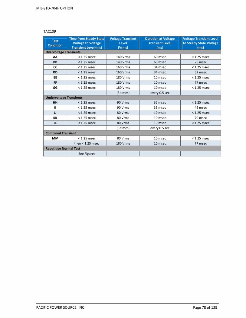
MIL-STD-704F OPTION
PACIFIC POWER SOURCE, INC Page 78 of 129
TAC109
Test Condition
Time from Steady State Voltage to Voltage
Transient Level (ms)
Voltage Transient Level
(Vrms)
Duration at Voltage Transient Level
(ms)
Voltage Transient Level to Steady State Voltage
(ms) Overvoltage Transients
AA < 1.25 msec 140 Vrms 60 msec < 1.25 msec BB < 1.25 msec 140 Vrms 60 msec 25 msec CC < 1.25 msec 160 Vrms 34 msec < 1.25 msec DD < 1.25 msec 160 Vrms 34 msec 52 msec EE < 1.25 msec 180 Vrms 10 msec < 1.25 msec FF < 1.25 msec 180 Vrms 10 msec 77 msec GG < 1.25 msec 180 Vrms 10 msec < 1.25 msec
(3 times) every 0.5 sec Undervoltage Transients
HH < 1.25 msec 90 Vrms 35 msec < 1.25 msec II < 1.25 msec 90 Vrms 35 msec 45 msec JJ < 1.25 msec 80 Vrms 10 msec < 1.25 msec KK < 1.25 msec 80 Vrms 10 msec 70 msec LL < 1.25 msec 80 Vrms 10 msec < 1.25 msec (3 times) every 0.5 sec
Combined Transient MM < 1.25 msec 80 Vrms 10 msec < 1.25 msec
then < 1.25 msec 180 Vrms 10 msec 77 msec Repetitive Normal Test
See Figures

MIL-STD-704F OPTION
PACIFIC POWER SOURCE, INC Page 79 of 129
Figure 13: Voltage Transition Pulse Details
Figure 14: Repetitive Voltage transients.
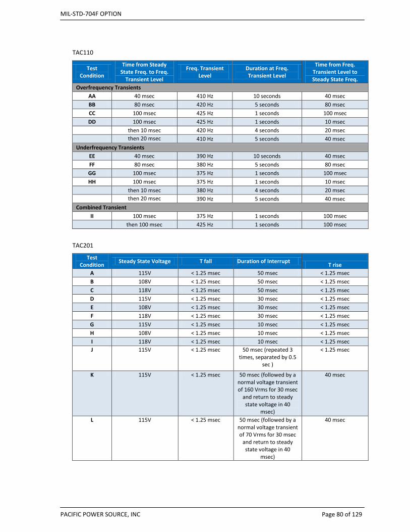
MIL-STD-704F OPTION
PACIFIC POWER SOURCE, INC Page 80 of 129
TAC110
Test Condition
Time from Steady State Freq. to Freq.
Transient Level
Freq. Transient Level
Duration at Freq. Transient Level
Time from Freq. Transient Level to Steady State Freq.
Overfrequency Transients AA 40 msec 410 Hz 10 seconds 40 msec BB 80 msec 420 Hz 5 seconds 80 msec CC 100 msec 425 Hz 1 seconds 100 msec DD 100 msec 425 Hz 1 seconds 10 msec
then 10 msec 420 Hz 4 seconds 20 msec then 20 msec 410 Hz 5 seconds 40 msec
Underfrequency Transients EE 40 msec 390 Hz 10 seconds 40 msec FF 80 msec 380 Hz 5 seconds 80 msec GG 100 msec 375 Hz 1 seconds 100 msec HH 100 msec 375 Hz 1 seconds 10 msec
then 10 msec 380 Hz 4 seconds 20 msec
then 20 msec 390 Hz 5 seconds 40 msec
Combined Transient II 100 msec 375 Hz 1 seconds 100 msec
then 100 msec 425 Hz 1 seconds 100 msec
TAC201
Test Condition Steady State Voltage T fall Duration of Interrupt T rise
A 115V < 1.25 msec 50 msec < 1.25 msec B 108V < 1.25 msec 50 msec < 1.25 msec C 118V < 1.25 msec 50 msec < 1.25 msec D 115V < 1.25 msec 30 msec < 1.25 msec E 108V < 1.25 msec 30 msec < 1.25 msec F 118V < 1.25 msec 30 msec < 1.25 msec G 115V < 1.25 msec 10 msec < 1.25 msec H 108V < 1.25 msec 10 msec < 1.25 msec I 118V < 1.25 msec 10 msec < 1.25 msec J 115V < 1.25 msec 50 msec (repeated 3
times, separated by 0.5 sec )
< 1.25 msec
K 115V < 1.25 msec 50 msec (followed by a normal voltage transient of 160 Vrms for 30 msec
and return to steady state voltage in 40
msec)
40 msec
L 115V < 1.25 msec 50 msec (followed by a normal voltage transient of 70 Vrms for 30 msec
and return to steady state voltage in 40
msec)
40 msec
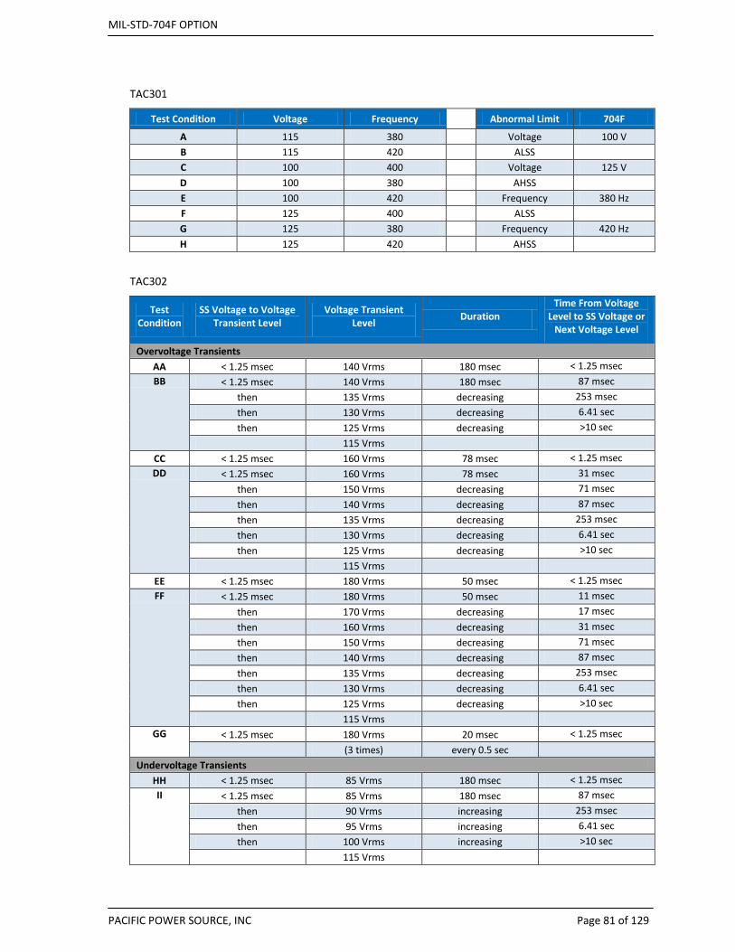
MIL-STD-704F OPTION
PACIFIC POWER SOURCE, INC Page 81 of 129
TAC301
Test Condition Voltage Frequency
Abnormal Limit 704F
A 115 380
Voltage 100 V B 115 420
ALSS
C 100 400
Voltage 125 V D 100 380
AHSS
E 100 420
Frequency 380 Hz F 125 400
ALSS
G 125 380
Frequency 420 Hz H 125 420
AHSS
TAC302
Test Condition
SS Voltage to Voltage Transient Level
Voltage Transient Level Duration
Time From Voltage Level to SS Voltage or
Next Voltage Level
Overvoltage Transients AA < 1.25 msec 140 Vrms 180 msec < 1.25 msec BB < 1.25 msec 140 Vrms 180 msec 87 msec
then 135 Vrms decreasing 253 msec then 130 Vrms decreasing 6.41 sec then 125 Vrms decreasing >10 sec
115 Vrms CC < 1.25 msec 160 Vrms 78 msec < 1.25 msec DD < 1.25 msec 160 Vrms 78 msec 31 msec
then 150 Vrms decreasing 71 msec then 140 Vrms decreasing 87 msec then 135 Vrms decreasing 253 msec then 130 Vrms decreasing 6.41 sec then 125 Vrms decreasing >10 sec
115 Vrms EE < 1.25 msec 180 Vrms 50 msec < 1.25 msec FF < 1.25 msec 180 Vrms 50 msec 11 msec
then 170 Vrms decreasing 17 msec then 160 Vrms decreasing 31 msec then 150 Vrms decreasing 71 msec then 140 Vrms decreasing 87 msec then 135 Vrms decreasing 253 msec then 130 Vrms decreasing 6.41 sec then 125 Vrms decreasing >10 sec
115 Vrms GG < 1.25 msec 180 Vrms 20 msec < 1.25 msec
(3 times) every 0.5 sec Undervoltage Transients
HH < 1.25 msec 85 Vrms 180 msec < 1.25 msec II < 1.25 msec 85 Vrms 180 msec 87 msec
then 90 Vrms increasing 253 msec then 95 Vrms increasing 6.41 sec then 100 Vrms increasing >10 sec
115 Vrms
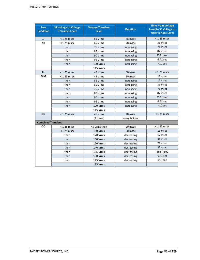
MIL-STD-704F OPTION
PACIFIC POWER SOURCE, INC Page 82 of 129
Test Condition
SS Voltage to Voltage Transient Level
Voltage Transient Level Duration
Time From Voltage Level to SS Voltage or
Next Voltage Level
JJ < 1.25 msec 65 Vrms 78 msec < 1.25 msec KK < 1.25 msec 65 Vrms 78 msec 31 msec
then 75 Vrms increasing 71 msec then 85 Vrms increasing 87 msec then 90 Vrms increasing 253 msec then 95 Vrms increasing 6.41 sec then 100 Vrms increasing >10 sec
115 Vrms LL < 1.25 msec 45 Vrms 50 msec < 1.25 msec
MM < 1.25 msec 45 Vrms 50 msec 11 msec then 55 Vrms increasing 17 msec then 65 Vrms increasing 31 msec then 75 Vrms increasing 71 msec then 85 Vrms increasing 87 msec then 90 Vrms increasing 253 msec then 95 Vrms increasing 6.41 sec then 100 Vrms increasing >10 sec
115 Vrms NN < 1.25 msec 45 Vrms 20 msec < 1.25 msec
(3 times) every 0.5 sec Combined Transient
OO < 1.25 msec 45 Vrms then 20 msec < 1.25 msec < 1.25 msec 180 Vrms 50 msec 11 msec
then 170 Vrms decreasing 17 msec then 160 Vrms decreasing 31 msec then 150 Vrms decreasing 71 msec then 140 Vrms decreasing 87 msec then 135 Vrms decreasing 253 msec then 130 Vrms decreasing 6.41 sec then 125 Vrms decreasing >10 sec
115 Vrms
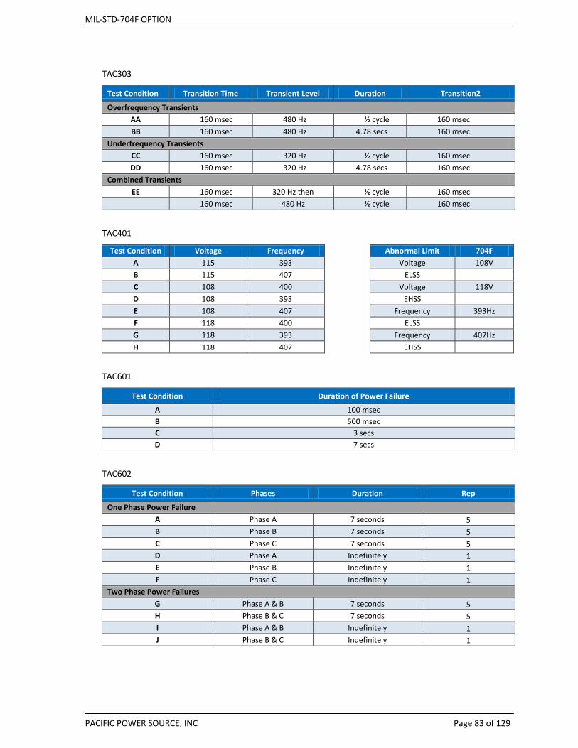
MIL-STD-704F OPTION
PACIFIC POWER SOURCE, INC Page 83 of 129
TAC303
Test Condition Transition Time Transient Level Duration Transition2
Overfrequency Transients AA 160 msec 480 Hz ½ cycle 160 msec BB 160 msec 480 Hz 4.78 secs 160 msec
Underfrequency Transients CC 160 msec 320 Hz ½ cycle 160 msec DD 160 msec 320 Hz 4.78 secs 160 msec
Combined Transients EE 160 msec 320 Hz then ½ cycle 160 msec
160 msec 480 Hz ½ cycle 160 msec
TAC401
Test Condition Voltage Frequency
Abnormal Limit 704F A 115 393
Voltage 108V
B 115 407
ELSS C 108 400
Voltage 118V
D 108 393
EHSS E 108 407
Frequency 393Hz
F 118 400
ELSS G 118 393
Frequency 407Hz
H 118 407
EHSS
TAC601
Test Condition Duration of Power Failure
A 100 msec B 500 msec C 3 secs D 7 secs
TAC602
Test Condition Phases Duration Rep
One Phase Power Failure A Phase A 7 seconds 5 B Phase B 7 seconds 5 C Phase C 7 seconds 5 D Phase A Indefinitely 1 E Phase B Indefinitely 1 F Phase C Indefinitely 1
Two Phase Power Failures G Phase A & B 7 seconds 5 H Phase B & C 7 seconds 5 I Phase A & B Indefinitely 1 J Phase B & C Indefinitely 1

MIL-STD-704F OPTION
PACIFIC POWER SOURCE, INC Page 84 of 129
TAC603
Test Condition Phases Duration
Physical Means Prevention Verify/Check If Not: Reversed Phase Rotation C-B-A 30 mins
Correct Phase Rotation A-B-C 30 mins
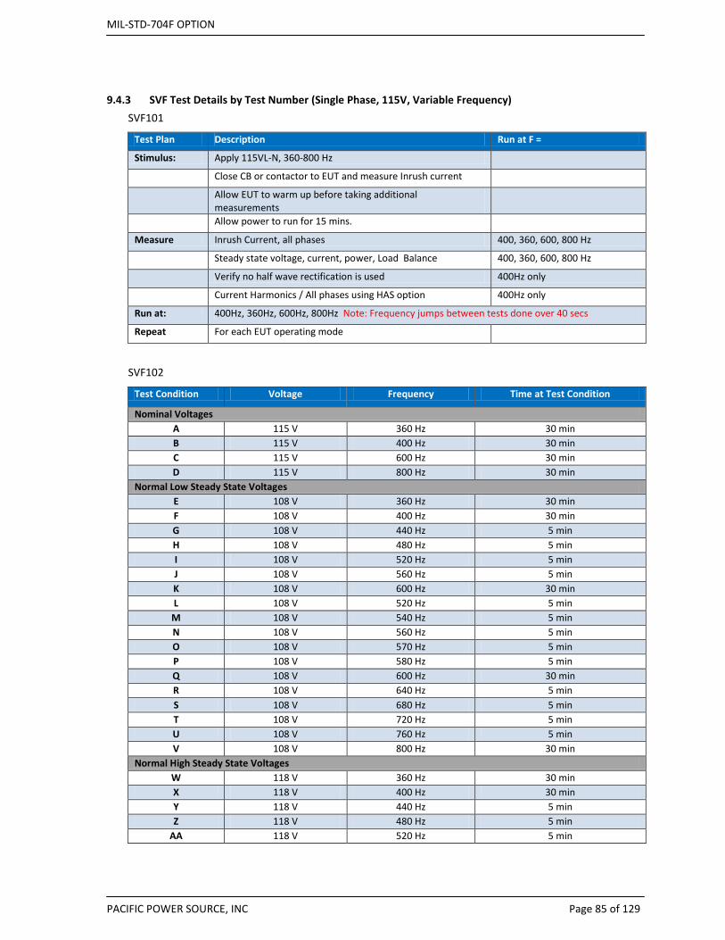
MIL-STD-704F OPTION
PACIFIC POWER SOURCE, INC Page 85 of 129
9.4.3 SVF Test Details by Test Number (Single Phase, 115V, Variable Frequency) SVF101
Test Plan Description Run at F =
Stimulus: Apply 115VL-N, 360-800 Hz
Close CB or contactor to EUT and measure Inrush current
Allow EUT to warm up before taking additional measurements
Allow power to run for 15 mins.
Measure Inrush Current, all phases 400, 360, 600, 800 Hz
Steady state voltage, current, power, Load Balance 400, 360, 600, 800 Hz
Verify no half wave rectification is used 400Hz only
Current Harmonics / All phases using HAS option 400Hz only
Run at: 400Hz, 360Hz, 600Hz, 800Hz Note: Frequency jumps between tests done over 40 secs
Repeat For each EUT operating mode
SVF102
Test Condition Voltage Frequency Time at Test Condition
Nominal Voltages A 115 V 360 Hz 30 min B 115 V 400 Hz 30 min C 115 V 600 Hz 30 min D 115 V 800 Hz 30 min
Normal Low Steady State Voltages E 108 V 360 Hz 30 min F 108 V 400 Hz 30 min G 108 V 440 Hz 5 min H 108 V 480 Hz 5 min I 108 V 520 Hz 5 min J 108 V 560 Hz 5 min K 108 V 600 Hz 30 min L 108 V 520 Hz 5 min
M 108 V 540 Hz 5 min N 108 V 560 Hz 5 min O 108 V 570 Hz 5 min P 108 V 580 Hz 5 min Q 108 V 600 Hz 30 min R 108 V 640 Hz 5 min S 108 V 680 Hz 5 min T 108 V 720 Hz 5 min U 108 V 760 Hz 5 min V 108 V 800 Hz 30 min
Normal High Steady State Voltages W 118 V 360 Hz 30 min X 118 V 400 Hz 30 min Y 118 V 440 Hz 5 min Z 118 V 480 Hz 5 min
AA 118 V 520 Hz 5 min
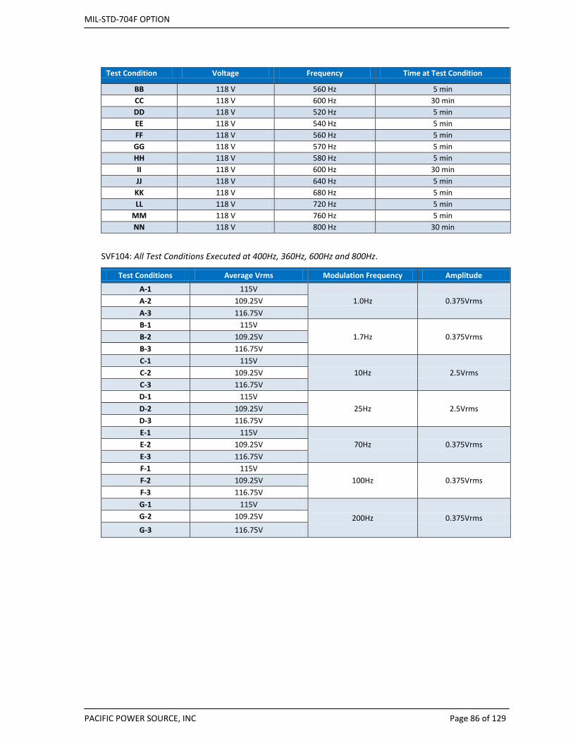
MIL-STD-704F OPTION
PACIFIC POWER SOURCE, INC Page 86 of 129
Test Condition Voltage Frequency Time at Test Condition
BB 118 V 560 Hz 5 min CC 118 V 600 Hz 30 min DD 118 V 520 Hz 5 min EE 118 V 540 Hz 5 min FF 118 V 560 Hz 5 min GG 118 V 570 Hz 5 min HH 118 V 580 Hz 5 min II 118 V 600 Hz 30 min JJ 118 V 640 Hz 5 min KK 118 V 680 Hz 5 min LL 118 V 720 Hz 5 min
MM 118 V 760 Hz 5 min NN 118 V 800 Hz 30 min
SVF104: All Test Conditions Executed at 400Hz, 360Hz, 600Hz and 800Hz.
Test Conditions Average Vrms Modulation Frequency Amplitude
A-1 115V 1.0Hz 0.375Vrms A-2 109.25V
A-3 116.75V B-1 115V
1.7Hz 0.375Vrms B-2 109.25V B-3 116.75V C-1 115V
10Hz 2.5Vrms C-2 109.25V C-3 116.75V D-1 115V
25Hz 2.5Vrms D-2 109.25V D-3 116.75V E-1 115V
70Hz 0.375Vrms E-2 109.25V E-3 116.75V F-1 115V
100Hz 0.375Vrms F-2 109.25V F-3 116.75V G-1 115V
200Hz 0.375Vrms G-2 109.25V
G-3 116.75V
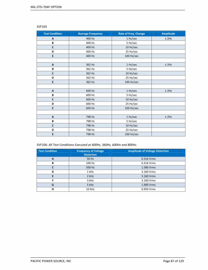
MIL-STD-704F OPTION
PACIFIC POWER SOURCE, INC Page 87 of 129
SVF105
Test Condition Average Frequency Rate of Freq. Change Amplitude
A 400 Hz 1 Hz/sec ± 2Hz B 400 Hz 5 Hz/sec C 400 Hz 10 Hz/sec D 400 Hz 25 Hz/sec E 400 Hz 100 Hz/sec
A 362 Hz 1 Hz/sec ± 2Hz B 362 Hz 5 Hz/sec C 362 Hz 10 Hz/sec D 362 Hz 25 Hz/sec E 362 Hz 100 Hz/sec
A 600 Hz 1 Hz/sec ± 2Hz B 600 Hz 5 Hz/sec C 600 Hz 10 Hz/sec D 600 Hz 25 Hz/sec E 600 Hz 100 Hz/sec
A 798 Hz 1 Hz/sec ± 2Hz B 798 Hz 5 Hz/sec C 798 Hz 10 Hz/sec D 798 Hz 25 Hz/sec E 798 Hz 100 Hz/sec
SVF106: All Test Conditions Executed at 400Hz, 360Hz, 600Hz and 800Hz.
Test Condition Frequency of Voltage Distortion
Amplitude of Voltage Distortion
A 50 Hz 0.316 Vrms B 100 Hz 0.316 Vrms C 500 Hz 1.580 Vrms D 1 kHz 3.160 Vrms E 2 kHz 3.160 Vrms F 3 kHz 3.160 Vrms G 5 kHz 1.900 Vrms H 10 kHz 0.950 Vrms
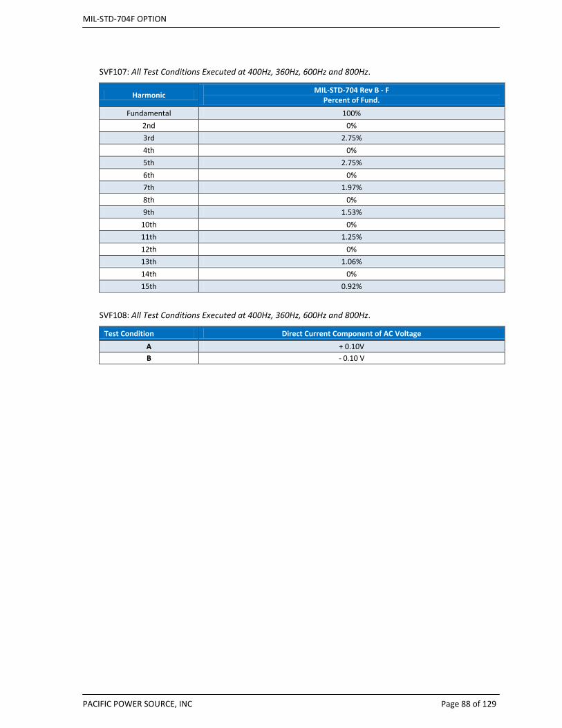
MIL-STD-704F OPTION
PACIFIC POWER SOURCE, INC Page 88 of 129
SVF107: All Test Conditions Executed at 400Hz, 360Hz, 600Hz and 800Hz.
Harmonic MIL-STD-704 Rev B - F Percent of Fund.
Fundamental 100% 2nd 0% 3rd 2.75% 4th 0% 5th 2.75% 6th 0% 7th 1.97% 8th 0% 9th 1.53%
10th 0% 11th 1.25% 12th 0% 13th 1.06% 14th 0% 15th 0.92%
SVF108: All Test Conditions Executed at 400Hz, 360Hz, 600Hz and 800Hz.
Test Condition Direct Current Component of AC Voltage A + 0.10V B - 0.10 V

MIL-STD-704F OPTION
PACIFIC POWER SOURCE, INC Page 89 of 129
SVF109: All Test Conditions Executed at 400Hz, 360Hz, 600Hz and 800Hz.
Test Condition Time from Steady State Voltage to
Voltage Transient Level (ms)
Voltage Transient Level
(Vrms)
Duration at Voltage
Transient Level (ms)
Voltage Transient Level to Steady
State Voltage (ms)
Overvoltage Transients A < ½ cycle 140 Vrms 60 msec < ½ cycle B < ½ cycle 140 Vrms 60 msec 25 msec C < ½ cycle 160 Vrms 34 msec < ½ cycle D < ½ cycle 160 Vrms 34 msec 52 msec E < ½ cycle 180 Vrms 10 msec < ½ cycle F < ½ cycle 180 Vrms 10 msec 77 msec G < ½ cycle 180 Vrms 10 msec < ½ cycle (3 times) every 0.5 sec
Undervoltage Transients H < ½ cycle 90 Vrms 35 msec < ½ cycle I < ½ cycle 90 Vrms 35 msec 45 msec J < ½ cycle 80 Vrms 10 msec < ½ cycle K < ½ cycle 80 Vrms 10 msec 70 msec L < ½ cycle 80 Vrms 10 msec < ½ cycle (3 times) every 0.5 sec
Combined Transient M < ½ cycle 80 Vrms 10 msec < ½ cycle then < ½ cycle 180 Vrms 10 msec 77 msec
Repetitive Normal Test See Figures
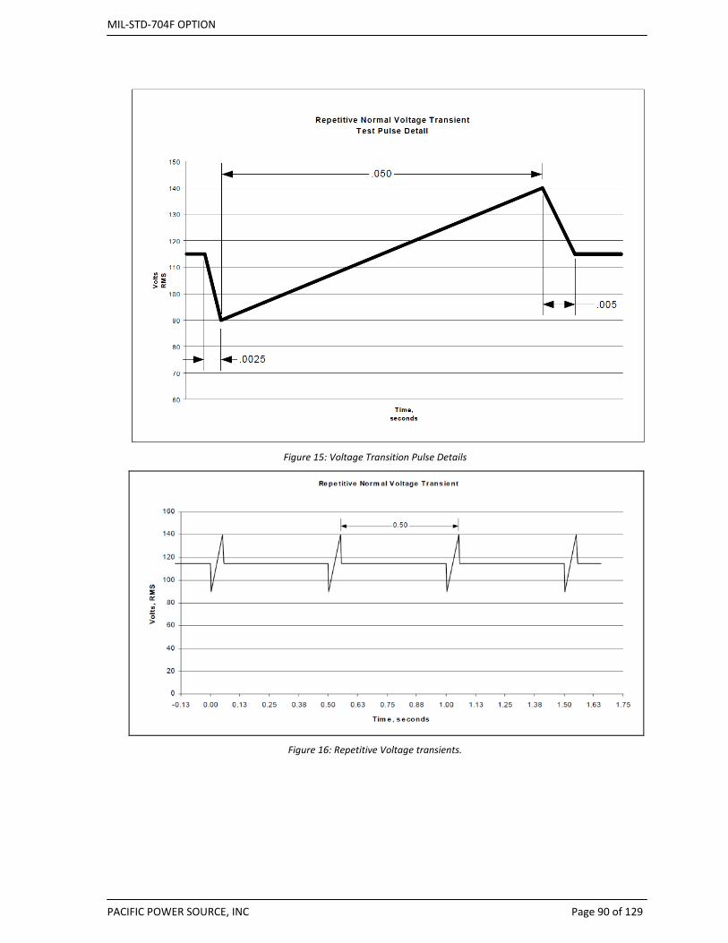
MIL-STD-704F OPTION
PACIFIC POWER SOURCE, INC Page 90 of 129
Figure 15: Voltage Transition Pulse Details
Figure 16: Repetitive Voltage transients.
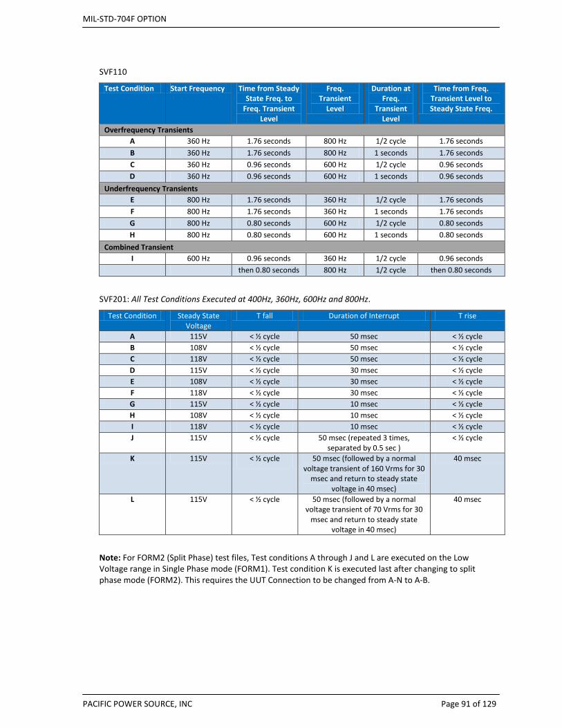
MIL-STD-704F OPTION
PACIFIC POWER SOURCE, INC Page 91 of 129
SVF110
Test Condition Start Frequency Time from Steady State Freq. to
Freq. Transient Level
Freq. Transient
Level
Duration at Freq.
Transient Level
Time from Freq. Transient Level to Steady State Freq.
Overfrequency Transients A 360 Hz 1.76 seconds 800 Hz 1/2 cycle 1.76 seconds B 360 Hz 1.76 seconds 800 Hz 1 seconds 1.76 seconds C 360 Hz 0.96 seconds 600 Hz 1/2 cycle 0.96 seconds D 360 Hz 0.96 seconds 600 Hz 1 seconds 0.96 seconds
Underfrequency Transients E 800 Hz 1.76 seconds 360 Hz 1/2 cycle 1.76 seconds F 800 Hz 1.76 seconds 360 Hz 1 seconds 1.76 seconds G 800 Hz 0.80 seconds 600 Hz 1/2 cycle 0.80 seconds H 800 Hz 0.80 seconds 600 Hz 1 seconds 0.80 seconds
Combined Transient I 600 Hz 0.96 seconds 360 Hz 1/2 cycle 0.96 seconds then 0.80 seconds 800 Hz 1/2 cycle then 0.80 seconds
SVF201: All Test Conditions Executed at 400Hz, 360Hz, 600Hz and 800Hz.
Test Condition Steady State Voltage
T fall Duration of Interrupt T rise
A 115V < ½ cycle 50 msec < ½ cycle B 108V < ½ cycle 50 msec < ½ cycle C 118V < ½ cycle 50 msec < ½ cycle D 115V < ½ cycle 30 msec < ½ cycle E 108V < ½ cycle 30 msec < ½ cycle F 118V < ½ cycle 30 msec < ½ cycle G 115V < ½ cycle 10 msec < ½ cycle H 108V < ½ cycle 10 msec < ½ cycle I 118V < ½ cycle 10 msec < ½ cycle J 115V < ½ cycle 50 msec (repeated 3 times,
separated by 0.5 sec ) < ½ cycle
K 115V < ½ cycle 50 msec (followed by a normal voltage transient of 160 Vrms for 30
msec and return to steady state voltage in 40 msec)
40 msec
L 115V < ½ cycle 50 msec (followed by a normal voltage transient of 70 Vrms for 30
msec and return to steady state voltage in 40 msec)
40 msec
Note: For FORM2 (Split Phase) test files, Test conditions A through J and L are executed on the Low Voltage range in Single Phase mode (FORM1). Test condition K is executed last after changing to split phase mode (FORM2). This requires the UUT Connection to be changed from A-N to A-B.
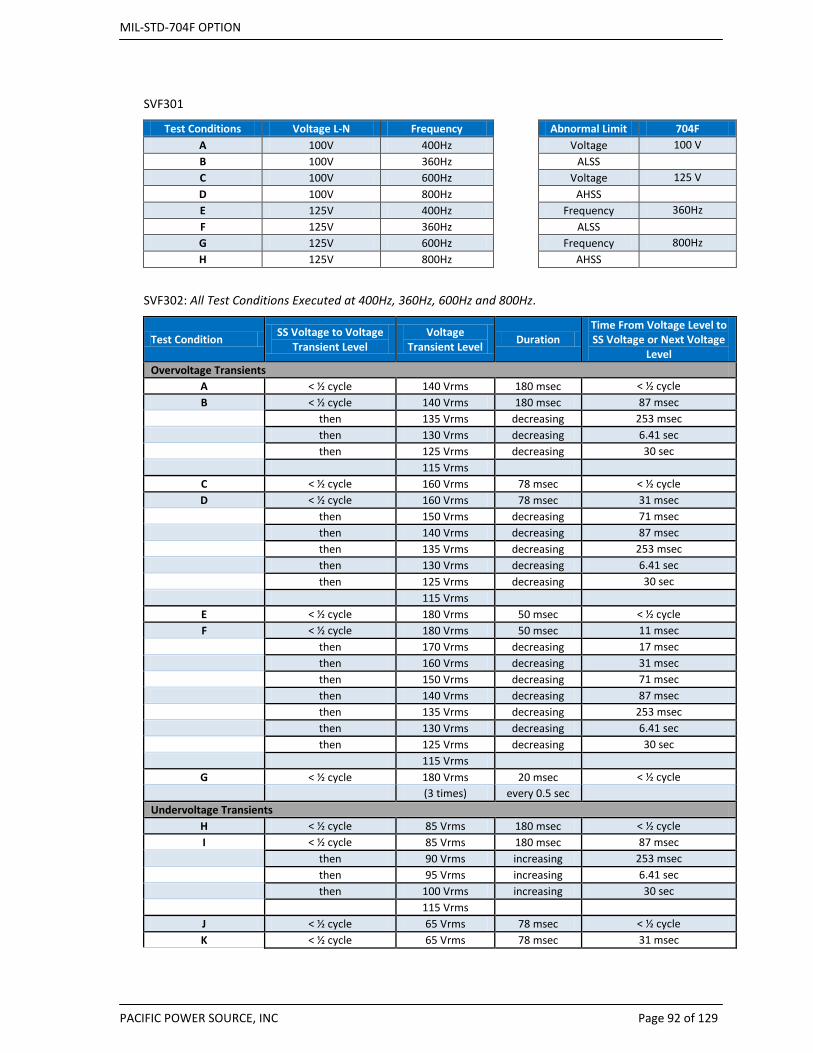
MIL-STD-704F OPTION
PACIFIC POWER SOURCE, INC Page 92 of 129
SVF301
Test Conditions Voltage L-N Frequency Abnormal Limit 704F A 100V 400Hz
Voltage 100 V
B 100V 360Hz
ALSS C 100V 600Hz
Voltage 125 V
D 100V 800Hz
AHSS E 125V 400Hz
Frequency 360Hz
F 125V 360Hz
ALSS G 125V 600Hz
Frequency 800Hz
H 125V 800Hz
AHSS
SVF302: All Test Conditions Executed at 400Hz, 360Hz, 600Hz and 800Hz.
Test Condition SS Voltage to Voltage Transient Level
Voltage Transient Level Duration
Time From Voltage Level to SS Voltage or Next Voltage
Level Overvoltage Transients
A < ½ cycle 140 Vrms 180 msec < ½ cycle B < ½ cycle 140 Vrms 180 msec 87 msec then 135 Vrms decreasing 253 msec then 130 Vrms decreasing 6.41 sec then 125 Vrms decreasing 30 sec 115 Vrms
C < ½ cycle 160 Vrms 78 msec < ½ cycle D < ½ cycle 160 Vrms 78 msec 31 msec then 150 Vrms decreasing 71 msec then 140 Vrms decreasing 87 msec then 135 Vrms decreasing 253 msec then 130 Vrms decreasing 6.41 sec then 125 Vrms decreasing 30 sec 115 Vrms
E < ½ cycle 180 Vrms 50 msec < ½ cycle F < ½ cycle 180 Vrms 50 msec 11 msec then 170 Vrms decreasing 17 msec then 160 Vrms decreasing 31 msec then 150 Vrms decreasing 71 msec then 140 Vrms decreasing 87 msec then 135 Vrms decreasing 253 msec then 130 Vrms decreasing 6.41 sec then 125 Vrms decreasing 30 sec 115 Vrms
G < ½ cycle 180 Vrms 20 msec < ½ cycle
(3 times) every 0.5 sec Undervoltage Transients
H < ½ cycle 85 Vrms 180 msec < ½ cycle I < ½ cycle 85 Vrms 180 msec 87 msec then 90 Vrms increasing 253 msec then 95 Vrms increasing 6.41 sec then 100 Vrms increasing 30 sec 115 Vrms J < ½ cycle 65 Vrms 78 msec < ½ cycle K < ½ cycle 65 Vrms 78 msec 31 msec
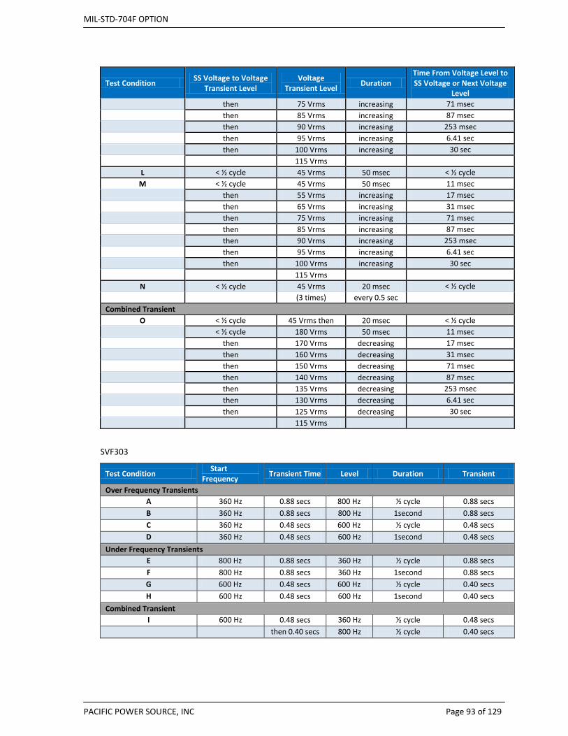
MIL-STD-704F OPTION
PACIFIC POWER SOURCE, INC Page 93 of 129
Test Condition SS Voltage to Voltage Transient Level
Voltage Transient Level Duration
Time From Voltage Level to SS Voltage or Next Voltage
Level then 75 Vrms increasing 71 msec then 85 Vrms increasing 87 msec then 90 Vrms increasing 253 msec then 95 Vrms increasing 6.41 sec then 100 Vrms increasing 30 sec 115 Vrms L < ½ cycle 45 Vrms 50 msec < ½ cycle
M < ½ cycle 45 Vrms 50 msec 11 msec then 55 Vrms increasing 17 msec then 65 Vrms increasing 31 msec then 75 Vrms increasing 71 msec then 85 Vrms increasing 87 msec then 90 Vrms increasing 253 msec then 95 Vrms increasing 6.41 sec then 100 Vrms increasing 30 sec 115 Vrms
N < ½ cycle 45 Vrms 20 msec < ½ cycle
(3 times) every 0.5 sec Combined Transient
O < ½ cycle 45 Vrms then 20 msec < ½ cycle < ½ cycle 180 Vrms 50 msec 11 msec then 170 Vrms decreasing 17 msec then 160 Vrms decreasing 31 msec then 150 Vrms decreasing 71 msec then 140 Vrms decreasing 87 msec then 135 Vrms decreasing 253 msec then 130 Vrms decreasing 6.41 sec then 125 Vrms decreasing 30 sec 115 Vrms
SVF303
Test Condition Start Frequency Transient Time Level Duration Transient
Over Frequency Transients A 360 Hz 0.88 secs 800 Hz ½ cycle 0.88 secs B 360 Hz 0.88 secs 800 Hz 1second 0.88 secs C 360 Hz 0.48 secs 600 Hz ½ cycle 0.48 secs D 360 Hz 0.48 secs 600 Hz 1second 0.48 secs
Under Frequency Transients E 800 Hz 0.88 secs 360 Hz ½ cycle 0.88 secs F 800 Hz 0.88 secs 360 Hz 1second 0.88 secs G 600 Hz 0.48 secs 600 Hz ½ cycle 0.40 secs H 600 Hz 0.48 secs 600 Hz 1second 0.40 secs
Combined Transient I 600 Hz 0.48 secs 360 Hz ½ cycle 0.48 secs then 0.40 secs 800 Hz ½ cycle 0.40 secs
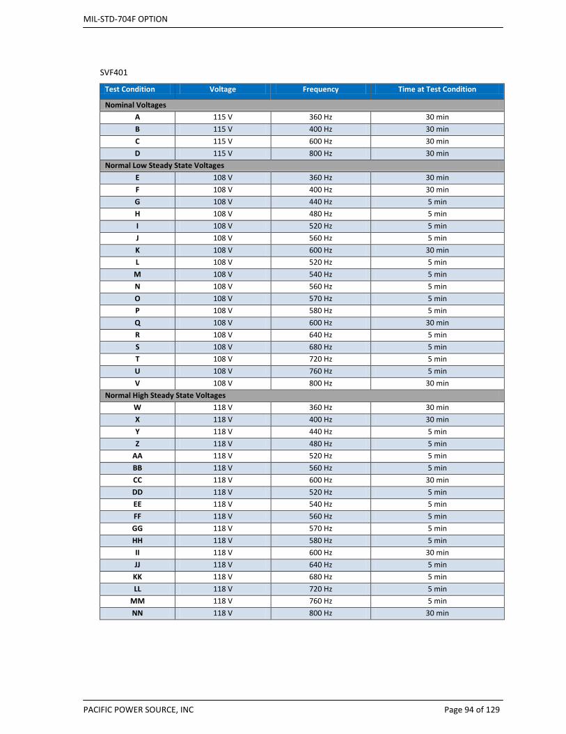
MIL-STD-704F OPTION
PACIFIC POWER SOURCE, INC Page 94 of 129
SVF401
Test Condition Voltage Frequency Time at Test Condition
Nominal Voltages A 115 V 360 Hz 30 min B 115 V 400 Hz 30 min C 115 V 600 Hz 30 min D 115 V 800 Hz 30 min
Normal Low Steady State Voltages E 108 V 360 Hz 30 min F 108 V 400 Hz 30 min G 108 V 440 Hz 5 min H 108 V 480 Hz 5 min I 108 V 520 Hz 5 min J 108 V 560 Hz 5 min K 108 V 600 Hz 30 min L 108 V 520 Hz 5 min
M 108 V 540 Hz 5 min N 108 V 560 Hz 5 min O 108 V 570 Hz 5 min P 108 V 580 Hz 5 min Q 108 V 600 Hz 30 min R 108 V 640 Hz 5 min S 108 V 680 Hz 5 min T 108 V 720 Hz 5 min U 108 V 760 Hz 5 min V 108 V 800 Hz 30 min
Normal High Steady State Voltages W 118 V 360 Hz 30 min X 118 V 400 Hz 30 min Y 118 V 440 Hz 5 min Z 118 V 480 Hz 5 min
AA 118 V 520 Hz 5 min BB 118 V 560 Hz 5 min CC 118 V 600 Hz 30 min DD 118 V 520 Hz 5 min EE 118 V 540 Hz 5 min FF 118 V 560 Hz 5 min GG 118 V 570 Hz 5 min HH 118 V 580 Hz 5 min II 118 V 600 Hz 30 min JJ 118 V 640 Hz 5 min KK 118 V 680 Hz 5 min LL 118 V 720 Hz 5 min
MM 118 V 760 Hz 5 min NN 118 V 800 Hz 30 min

MIL-STD-704F OPTION
PACIFIC POWER SOURCE, INC Page 95 of 129
SVF601: All Test Conditions Executed at 400Hz, 360Hz, 600Hz and 800Hz.
Test Condition Duration of Power Failure
A 100 msec B 500 msec C 3 secs D 7 secs
SVF603: All Test Conditions Executed at 400Hz, 360Hz, 600Hz and 800Hz.
Test Condition Phases Duration
Physical Means Prevention Verify/Check If Not: Reversed Phase Rotation C-B-A 30 mins
Correct Phase Rotation A-B-C 30 mins

MIL-STD-704F OPTION
PACIFIC POWER SOURCE, INC Page 96 of 129
9.4.4 TVF Test Details by Test Number (Three Phase, 115V, Variable Frequency) TVF101
Test Plan Description Run at F =
Stimulus: Apply 115VL-N, 360-800 Hz
Close CB or contactor to EUT and measure Inrush current
Allow EUT to warm up before taking additional measurements
Allow power to run for 15 mins.
Measure Inrush Current, all phases 400, 360, 600, 800 Hz
Steady state voltage, current, power, Load Balance 400, 360, 600, 800 Hz
Verify no half wave rectification is used 400Hz only
Current Harmonics / All phases using HAS option 400Hz only
Run at: 400Hz, 360Hz, 600Hz, 800Hz Note: Frequency jumps between tests done over 40 secs
Repeat For each EUT operating mode
TVF102
Test Condition Voltage Frequency Time at Test Condition
Nominal Voltages A 115 V 360 Hz 30 min B 115 V 400 Hz 30 min C 115 V 600 Hz 30 min D 115 V 800 Hz 30 min
Normal Low Steady State Voltages E 108 V 360 Hz 30 min F 108 V 400 Hz 30 min G 108 V 440 Hz 5 min H 108 V 480 Hz 5 min I 108 V 520 Hz 5 min J 108 V 560 Hz 5 min K 108 V 600 Hz 30 min L 108 V 520 Hz 5 min
M 108 V 540 Hz 5 min N 108 V 560 Hz 5 min O 108 V 570 Hz 5 min P 108 V 580 Hz 5 min Q 108 V 600 Hz 30 min R 108 V 640 Hz 5 min S 108 V 680 Hz 5 min T 108 V 720 Hz 5 min U 108 V 760 Hz 5 min V 108 V 800 Hz 30 min
Normal High Steady State Voltages W 118 V 360 Hz 30 min X 118 V 400 Hz 30 min Y 118 V 440 Hz 5 min Z 118 V 480 Hz 5 min
AA 118 V 520 Hz 5 min
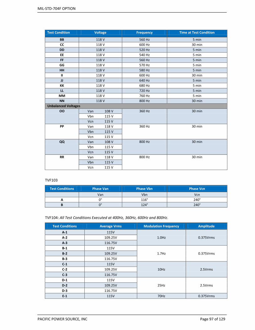
MIL-STD-704F OPTION
PACIFIC POWER SOURCE, INC Page 97 of 129
Test Condition Voltage Frequency Time at Test Condition
BB 118 V 560 Hz 5 min CC 118 V 600 Hz 30 min DD 118 V 520 Hz 5 min EE 118 V 540 Hz 5 min FF 118 V 560 Hz 5 min GG 118 V 570 Hz 5 min HH 118 V 580 Hz 5 min II 118 V 600 Hz 30 min JJ 118 V 640 Hz 5 min KK 118 V 680 Hz 5 min LL 118 V 720 Hz 5 min
MM 118 V 760 Hz 5 min NN 118 V 800 Hz 30 min
Unbalanced Voltages OO Van 108 V 360 Hz 30 min
Vbn 115 V Vcn 115 V
PP Van 118 V 360 Hz 30 min Vbn 115 V Vcn 115 V
QQ Van 108 V 800 Hz 30 min Vbn 115 V Vcn 115 V
RR Van 118 V 800 Hz 30 min Vbn 115 V Vcn 115 V
TVF103
Test Conditions Phase Van Phase Vbn Phase Vcn
Van Vbn Vcn A 0° 116° 240° B 0° 124° 240°
TVF104: All Test Conditions Executed at 400Hz, 360Hz, 600Hz and 800Hz.
Test Conditions Average Vrms Modulation Frequency Amplitude
A-1 115V 1.0Hz 0.375Vrms A-2 109.25V
A-3 116.75V B-1 115V
1.7Hz 0.375Vrms B-2 109.25V B-3 116.75V C-1 115V
10Hz 2.5Vrms C-2 109.25V C-3 116.75V D-1 115V
25Hz 2.5Vrms D-2 109.25V D-3 116.75V E-1 115V 70Hz 0.375Vrms
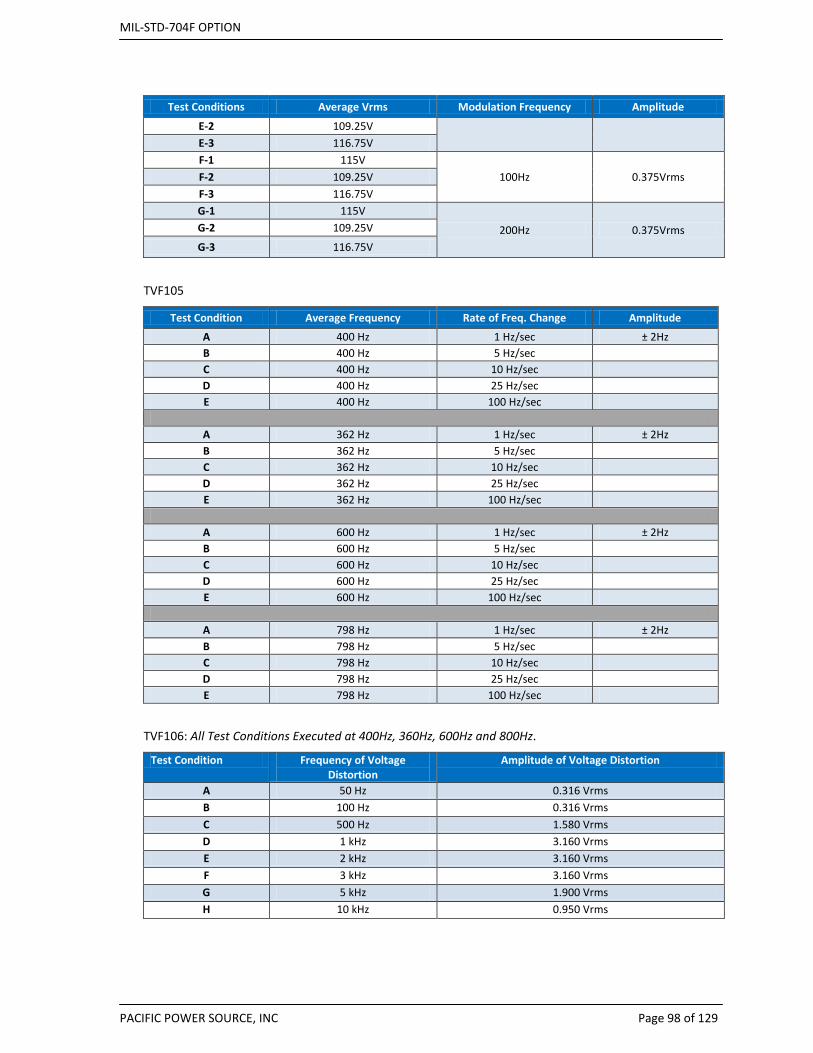
MIL-STD-704F OPTION
PACIFIC POWER SOURCE, INC Page 98 of 129
Test Conditions Average Vrms Modulation Frequency Amplitude
E-2 109.25V E-3 116.75V F-1 115V
100Hz 0.375Vrms F-2 109.25V F-3 116.75V G-1 115V
200Hz 0.375Vrms G-2 109.25V
G-3 116.75V
TVF105
Test Condition Average Frequency Rate of Freq. Change Amplitude
A 400 Hz 1 Hz/sec ± 2Hz B 400 Hz 5 Hz/sec C 400 Hz 10 Hz/sec D 400 Hz 25 Hz/sec E 400 Hz 100 Hz/sec
A 362 Hz 1 Hz/sec ± 2Hz B 362 Hz 5 Hz/sec C 362 Hz 10 Hz/sec D 362 Hz 25 Hz/sec E 362 Hz 100 Hz/sec
A 600 Hz 1 Hz/sec ± 2Hz B 600 Hz 5 Hz/sec C 600 Hz 10 Hz/sec D 600 Hz 25 Hz/sec E 600 Hz 100 Hz/sec
A 798 Hz 1 Hz/sec ± 2Hz B 798 Hz 5 Hz/sec C 798 Hz 10 Hz/sec D 798 Hz 25 Hz/sec E 798 Hz 100 Hz/sec
TVF106: All Test Conditions Executed at 400Hz, 360Hz, 600Hz and 800Hz.
Test Condition Frequency of Voltage Distortion
Amplitude of Voltage Distortion
A 50 Hz 0.316 Vrms B 100 Hz 0.316 Vrms C 500 Hz 1.580 Vrms D 1 kHz 3.160 Vrms E 2 kHz 3.160 Vrms F 3 kHz 3.160 Vrms G 5 kHz 1.900 Vrms H 10 kHz 0.950 Vrms

MIL-STD-704F OPTION
PACIFIC POWER SOURCE, INC Page 99 of 129
TVF107: All Test Conditions Executed at 400Hz, 360Hz, 600Hz and 800Hz.
Harmonic MIL-STD-704 Rev B - F Percent of Fund.
Fundamental 100% 2nd 0% 3rd 2.75% 4th 0% 5th 2.75% 6th 0% 7th 1.97% 8th 0% 9th 1.53%
10th 0% 11th 1.25% 12th 0% 13th 1.06% 14th 0% 15th 0.92%
TVF108: All Test Conditions Executed at 400Hz, 360Hz, 600Hz and 800Hz.
Test Condition Direct Current Component of AC Voltage A + 0.10V B - 0.10 V
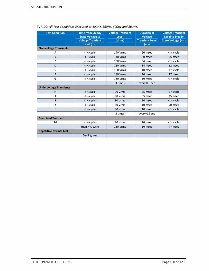
MIL-STD-704F OPTION
PACIFIC POWER SOURCE, INC Page 100 of 129
TVF109: All Test Conditions Executed at 400Hz, 360Hz, 600Hz and 800Hz.
Test Condition Time from Steady State Voltage to
Voltage Transient Level (ms)
Voltage Transient Level
(Vrms)
Duration at Voltage
Transient Level (ms)
Voltage Transient Level to Steady
State Voltage (ms)
Overvoltage Transients A < ½ cycle 140 Vrms 60 msec < ½ cycle B < ½ cycle 140 Vrms 60 msec 25 msec C < ½ cycle 160 Vrms 34 msec < ½ cycle D < ½ cycle 160 Vrms 34 msec 52 msec E < ½ cycle 180 Vrms 10 msec < ½ cycle F < ½ cycle 180 Vrms 10 msec 77 msec G < ½ cycle 180 Vrms 10 msec < ½ cycle (3 times) every 0.5 sec
Undervoltage Transients H < ½ cycle 90 Vrms 35 msec < ½ cycle I < ½ cycle 90 Vrms 35 msec 45 msec J < ½ cycle 80 Vrms 10 msec < ½ cycle K < ½ cycle 80 Vrms 10 msec 70 msec L < ½ cycle 80 Vrms 10 msec < ½ cycle (3 times) every 0.5 sec
Combined Transient M < ½ cycle 80 Vrms 10 msec < ½ cycle then < ½ cycle 180 Vrms 10 msec 77 msec
Repetitive Normal Test See Figures

MIL-STD-704F OPTION
PACIFIC POWER SOURCE, INC Page 101 of 129
Figure 17: Voltage Transition Pulse Details
Figure 18: Repetitive Voltage transients.
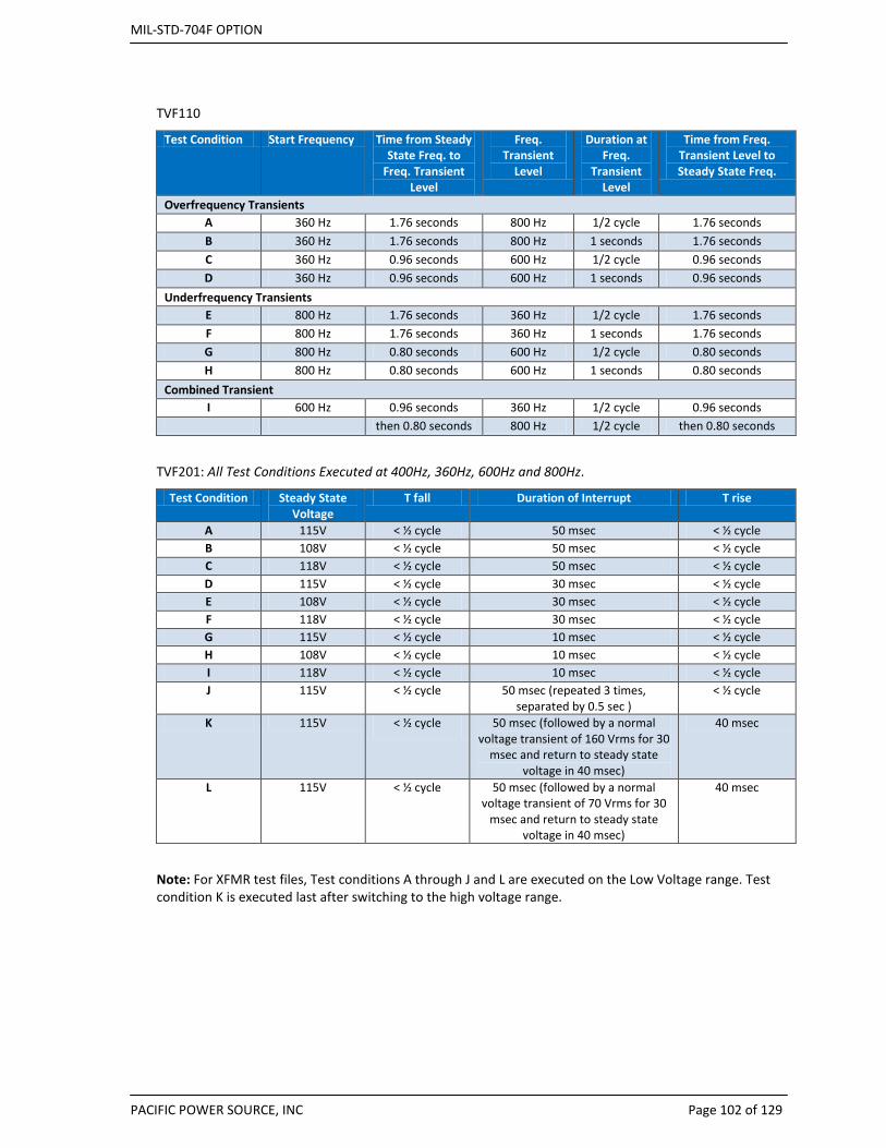
MIL-STD-704F OPTION
PACIFIC POWER SOURCE, INC Page 102 of 129
TVF110
Test Condition Start Frequency Time from Steady State Freq. to
Freq. Transient Level
Freq. Transient
Level
Duration at Freq.
Transient Level
Time from Freq. Transient Level to Steady State Freq.
Overfrequency Transients A 360 Hz 1.76 seconds 800 Hz 1/2 cycle 1.76 seconds B 360 Hz 1.76 seconds 800 Hz 1 seconds 1.76 seconds C 360 Hz 0.96 seconds 600 Hz 1/2 cycle 0.96 seconds D 360 Hz 0.96 seconds 600 Hz 1 seconds 0.96 seconds
Underfrequency Transients E 800 Hz 1.76 seconds 360 Hz 1/2 cycle 1.76 seconds F 800 Hz 1.76 seconds 360 Hz 1 seconds 1.76 seconds G 800 Hz 0.80 seconds 600 Hz 1/2 cycle 0.80 seconds H 800 Hz 0.80 seconds 600 Hz 1 seconds 0.80 seconds
Combined Transient I 600 Hz 0.96 seconds 360 Hz 1/2 cycle 0.96 seconds then 0.80 seconds 800 Hz 1/2 cycle then 0.80 seconds
TVF201: All Test Conditions Executed at 400Hz, 360Hz, 600Hz and 800Hz.
Test Condition Steady State Voltage
T fall Duration of Interrupt T rise
A 115V < ½ cycle 50 msec < ½ cycle B 108V < ½ cycle 50 msec < ½ cycle C 118V < ½ cycle 50 msec < ½ cycle D 115V < ½ cycle 30 msec < ½ cycle E 108V < ½ cycle 30 msec < ½ cycle F 118V < ½ cycle 30 msec < ½ cycle G 115V < ½ cycle 10 msec < ½ cycle H 108V < ½ cycle 10 msec < ½ cycle I 118V < ½ cycle 10 msec < ½ cycle J 115V < ½ cycle 50 msec (repeated 3 times,
separated by 0.5 sec ) < ½ cycle
K 115V < ½ cycle 50 msec (followed by a normal voltage transient of 160 Vrms for 30
msec and return to steady state voltage in 40 msec)
40 msec
L 115V < ½ cycle 50 msec (followed by a normal voltage transient of 70 Vrms for 30
msec and return to steady state voltage in 40 msec)
40 msec
Note: For XFMR test files, Test conditions A through J and L are executed on the Low Voltage range. Test condition K is executed last after switching to the high voltage range.
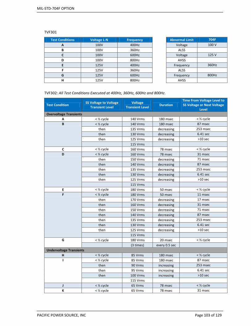
MIL-STD-704F OPTION
PACIFIC POWER SOURCE, INC Page 103 of 129
TVF301
Test Conditions Voltage L-N Frequency Abnormal Limit 704F A 100V 400Hz
Voltage 100 V
B 100V 360Hz
ALSS C 100V 600Hz
Voltage 125 V
D 100V 800Hz
AHSS E 125V 400Hz
Frequency 360Hz
F 125V 360Hz
ALSS G 125V 600Hz
Frequency 800Hz
H 125V 800Hz
AHSS
TVF302: All Test Conditions Executed at 400Hz, 360Hz, 600Hz and 800Hz.
Test Condition SS Voltage to Voltage Transient Level
Voltage Transient Level Duration
Time From Voltage Level to SS Voltage or Next Voltage
Level Overvoltage Transients
A < ½ cycle 140 Vrms 180 msec < ½ cycle B < ½ cycle 140 Vrms 180 msec 87 msec
then 135 Vrms decreasing 253 msec then 130 Vrms decreasing 6.41 sec then 125 Vrms decreasing >10 sec
115 Vrms C < ½ cycle 160 Vrms 78 msec < ½ cycle D < ½ cycle 160 Vrms 78 msec 31 msec
then 150 Vrms decreasing 71 msec then 140 Vrms decreasing 87 msec then 135 Vrms decreasing 253 msec then 130 Vrms decreasing 6.41 sec then 125 Vrms decreasing >10 sec
115 Vrms E < ½ cycle 180 Vrms 50 msec < ½ cycle F < ½ cycle 180 Vrms 50 msec 11 msec
then 170 Vrms decreasing 17 msec then 160 Vrms decreasing 31 msec then 150 Vrms decreasing 71 msec then 140 Vrms decreasing 87 msec then 135 Vrms decreasing 253 msec then 130 Vrms decreasing 6.41 sec then 125 Vrms decreasing >10 sec
115 Vrms G < ½ cycle 180 Vrms 20 msec < ½ cycle
(3 times) every 0.5 sec Undervoltage Transients
H < ½ cycle 85 Vrms 180 msec < ½ cycle I < ½ cycle 85 Vrms 180 msec 87 msec
then 90 Vrms increasing 253 msec then 95 Vrms increasing 6.41 sec then 100 Vrms increasing >10 sec
115 Vrms J < ½ cycle 65 Vrms 78 msec < ½ cycle K < ½ cycle 65 Vrms 78 msec 31 msec
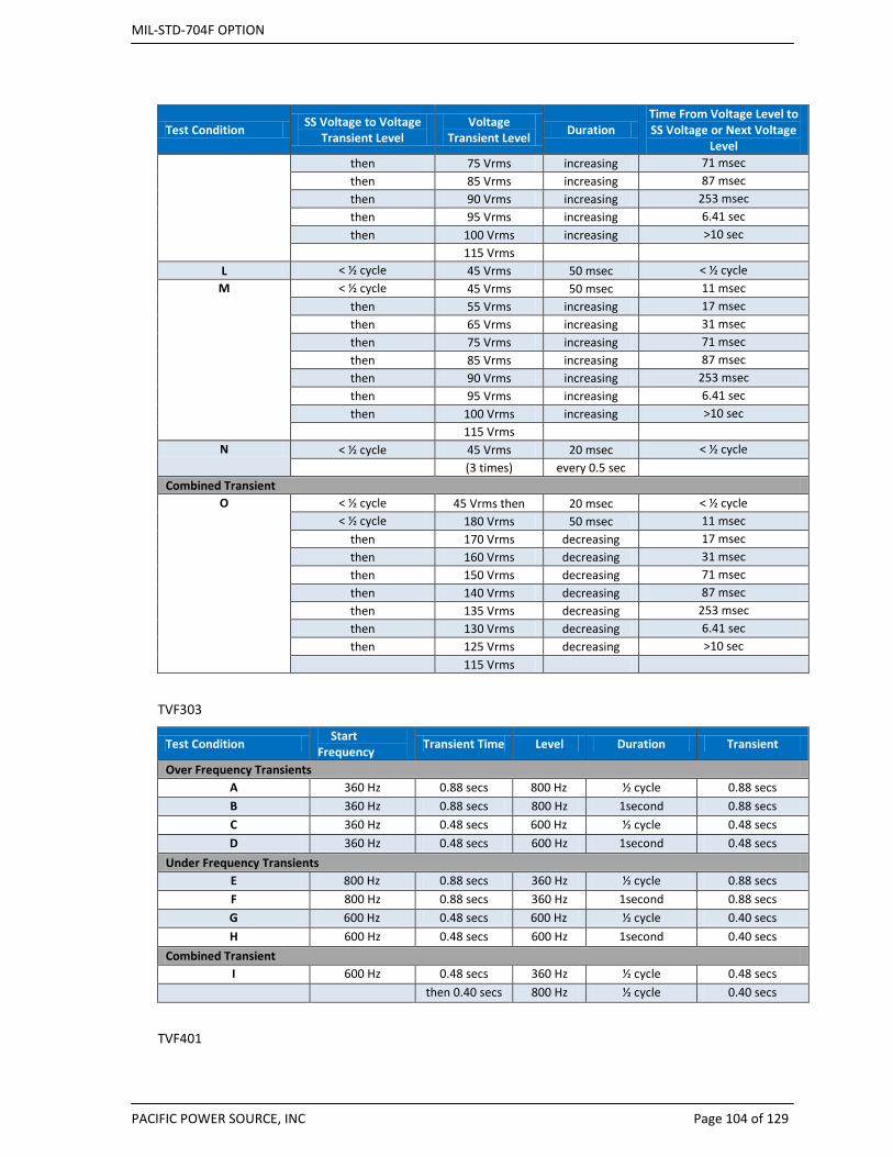
MIL-STD-704F OPTION
PACIFIC POWER SOURCE, INC Page 104 of 129
Test Condition SS Voltage to Voltage Transient Level
Voltage Transient Level Duration
Time From Voltage Level to SS Voltage or Next Voltage
Level then 75 Vrms increasing 71 msec then 85 Vrms increasing 87 msec then 90 Vrms increasing 253 msec then 95 Vrms increasing 6.41 sec then 100 Vrms increasing >10 sec
115 Vrms L < ½ cycle 45 Vrms 50 msec < ½ cycle
M < ½ cycle 45 Vrms 50 msec 11 msec then 55 Vrms increasing 17 msec then 65 Vrms increasing 31 msec then 75 Vrms increasing 71 msec then 85 Vrms increasing 87 msec then 90 Vrms increasing 253 msec then 95 Vrms increasing 6.41 sec then 100 Vrms increasing >10 sec
115 Vrms N < ½ cycle 45 Vrms 20 msec < ½ cycle
(3 times) every 0.5 sec Combined Transient
O < ½ cycle 45 Vrms then 20 msec < ½ cycle < ½ cycle 180 Vrms 50 msec 11 msec
then 170 Vrms decreasing 17 msec then 160 Vrms decreasing 31 msec then 150 Vrms decreasing 71 msec then 140 Vrms decreasing 87 msec then 135 Vrms decreasing 253 msec then 130 Vrms decreasing 6.41 sec then 125 Vrms decreasing >10 sec
115 Vrms
TVF303
Test Condition Start Frequency Transient Time Level Duration Transient
Over Frequency Transients A 360 Hz 0.88 secs 800 Hz ½ cycle 0.88 secs B 360 Hz 0.88 secs 800 Hz 1second 0.88 secs C 360 Hz 0.48 secs 600 Hz ½ cycle 0.48 secs D 360 Hz 0.48 secs 600 Hz 1second 0.48 secs
Under Frequency Transients E 800 Hz 0.88 secs 360 Hz ½ cycle 0.88 secs F 800 Hz 0.88 secs 360 Hz 1second 0.88 secs G 600 Hz 0.48 secs 600 Hz ½ cycle 0.40 secs H 600 Hz 0.48 secs 600 Hz 1second 0.40 secs
Combined Transient I 600 Hz 0.48 secs 360 Hz ½ cycle 0.48 secs then 0.40 secs 800 Hz ½ cycle 0.40 secs
TVF401
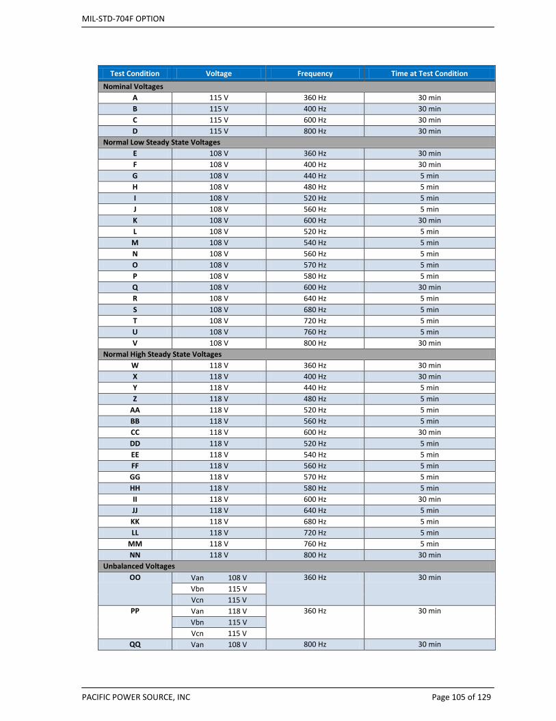
MIL-STD-704F OPTION
PACIFIC POWER SOURCE, INC Page 105 of 129
Test Condition Voltage Frequency Time at Test Condition
Nominal Voltages A 115 V 360 Hz 30 min B 115 V 400 Hz 30 min C 115 V 600 Hz 30 min D 115 V 800 Hz 30 min
Normal Low Steady State Voltages E 108 V 360 Hz 30 min F 108 V 400 Hz 30 min G 108 V 440 Hz 5 min H 108 V 480 Hz 5 min I 108 V 520 Hz 5 min J 108 V 560 Hz 5 min K 108 V 600 Hz 30 min L 108 V 520 Hz 5 min
M 108 V 540 Hz 5 min N 108 V 560 Hz 5 min O 108 V 570 Hz 5 min P 108 V 580 Hz 5 min Q 108 V 600 Hz 30 min R 108 V 640 Hz 5 min S 108 V 680 Hz 5 min T 108 V 720 Hz 5 min U 108 V 760 Hz 5 min V 108 V 800 Hz 30 min
Normal High Steady State Voltages W 118 V 360 Hz 30 min X 118 V 400 Hz 30 min Y 118 V 440 Hz 5 min Z 118 V 480 Hz 5 min
AA 118 V 520 Hz 5 min BB 118 V 560 Hz 5 min CC 118 V 600 Hz 30 min DD 118 V 520 Hz 5 min EE 118 V 540 Hz 5 min FF 118 V 560 Hz 5 min GG 118 V 570 Hz 5 min HH 118 V 580 Hz 5 min II 118 V 600 Hz 30 min JJ 118 V 640 Hz 5 min KK 118 V 680 Hz 5 min LL 118 V 720 Hz 5 min
MM 118 V 760 Hz 5 min NN 118 V 800 Hz 30 min
Unbalanced Voltages OO Van 108 V 360 Hz 30 min
Vbn 115 V Vcn 115 V
PP Van 118 V 360 Hz 30 min Vbn 115 V Vcn 115 V
QQ Van 108 V 800 Hz 30 min
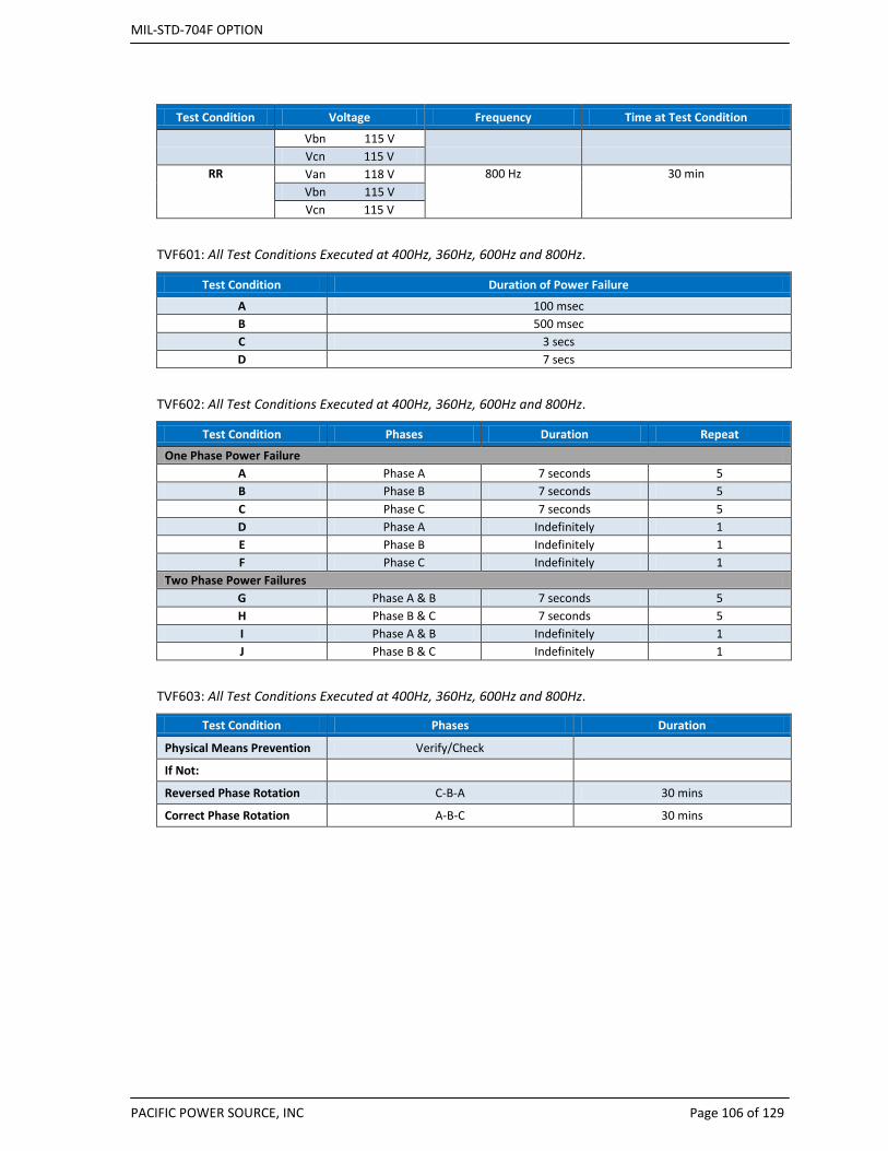
MIL-STD-704F OPTION
PACIFIC POWER SOURCE, INC Page 106 of 129
Test Condition Voltage Frequency Time at Test Condition
Vbn 115 V Vcn 115 V
RR Van 118 V 800 Hz 30 min Vbn 115 V Vcn 115 V
TVF601: All Test Conditions Executed at 400Hz, 360Hz, 600Hz and 800Hz.
Test Condition Duration of Power Failure
A 100 msec B 500 msec C 3 secs D 7 secs
TVF602: All Test Conditions Executed at 400Hz, 360Hz, 600Hz and 800Hz.
Test Condition Phases Duration Repeat
One Phase Power Failure A Phase A 7 seconds 5 B Phase B 7 seconds 5 C Phase C 7 seconds 5 D Phase A Indefinitely 1 E Phase B Indefinitely 1 F Phase C Indefinitely 1
Two Phase Power Failures G Phase A & B 7 seconds 5 H Phase B & C 7 seconds 5 I Phase A & B Indefinitely 1 J Phase B & C Indefinitely 1
TVF603: All Test Conditions Executed at 400Hz, 360Hz, 600Hz and 800Hz.
Test Condition Phases Duration
Physical Means Prevention Verify/Check If Not: Reversed Phase Rotation C-B-A 30 mins
Correct Phase Rotation A-B-C 30 mins

MIL-STD-704F OPTION
PACIFIC POWER SOURCE, INC Page 107 of 129
9.4.5 SXF Test Details by Test Number (Single Phase, 115V, 60 Hz) SXF101
Test Plan Description
Stimulus: Apply 115VL-N, 60Hz Close CB or contactor to EUT and measure Inrush current Allow EUT to warm up before taking additional measurements Allow power to run for 15 mins. Measure Inrush Current, all phases Steady state voltage, current, power Verify no half wave rectification is used Current Harmonics / All phases using HAS option Repeat For each EUT operating mode
SXF102
Test Condition Voltage L-N Frequency
Balanced Voltages A 115V 60.0Hz B 115V 59.5Hz C 115V 60.5Hz D 108V 60.0Hz E 108V 59.5Hz F 108V 60.5Hz G 118V 60.0Hz H 118V 59.5Hz I 118V 60.5Hz
SXF104
Test Conditions Average Vrms Modulation Frequency Amplitude
A 115V 1.0Hz 0.375Vrms 109V 117V
B 115V 1.5Hz 2.5Vrms 109V 117V
C 115V 4Hz 2.5Vrms 109V 117V
D 115V 10Hz 0.375Vrms 109V 117V
E 115V 15Hz 0.375Vrms 109V 117V
F 115V 30Hz 0.375Vrms 109V 117V
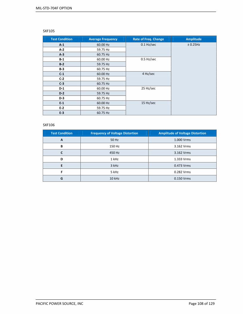
MIL-STD-704F OPTION
PACIFIC POWER SOURCE, INC Page 108 of 129
SXF105
Test Condition Average Frequency Rate of Freq. Change Amplitude A-1 60.00 Hz 0.1 Hz/sec ± 0.25Hz A-2 59.75 Hz A-3 60.75 Hz B-1 60.00 Hz 0.5 Hz/sec B-2 59.75 Hz B-3 60.75 Hz C-1 60.00 Hz 4 Hz/sec C-2 59.75 Hz C-3 60.75 Hz D-1 60.00 Hz 25 Hz/sec D-2 59.75 Hz D-3 60.75 Hz E-1 60.00 Hz 15 Hz/sec E-2 59.75 Hz E-3 60.75 Hz
SXF106
Test Condition Frequency of Voltage Distortion Amplitude of Voltage Distortion
A 50 Hz 1.000 Vrms
B 150 Hz 3.162 Vrms
C 450 Hz 3.162 Vrms
D 1 kHz 1.333 Vrms
E 3 kHz 0.473 Vrms
F 5 kHz 0.282 Vrms
G 10 kHz 0.150 Vrms
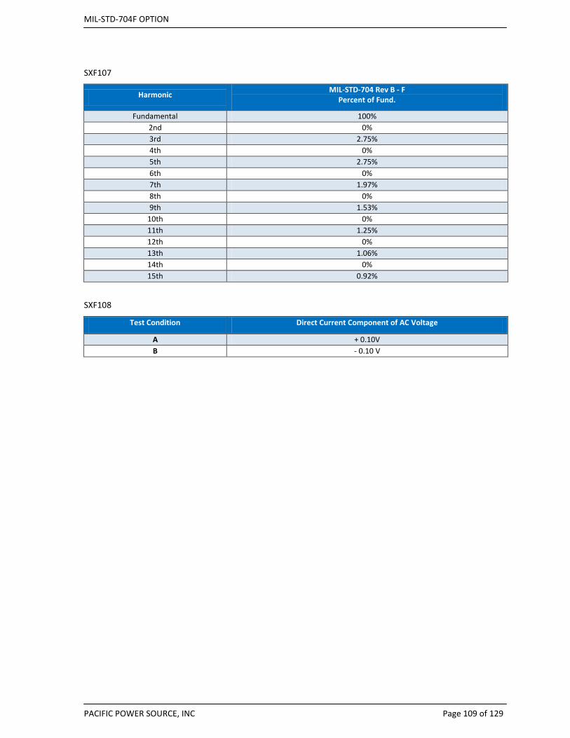
MIL-STD-704F OPTION
PACIFIC POWER SOURCE, INC Page 109 of 129
SXF107
Harmonic MIL-STD-704 Rev B - F Percent of Fund.
Fundamental 100% 2nd 0% 3rd 2.75% 4th 0% 5th 2.75% 6th 0% 7th 1.97% 8th 0% 9th 1.53%
10th 0% 11th 1.25% 12th 0% 13th 1.06% 14th 0% 15th 0.92%
SXF108
Test Condition Direct Current Component of AC Voltage
A + 0.10V B - 0.10 V
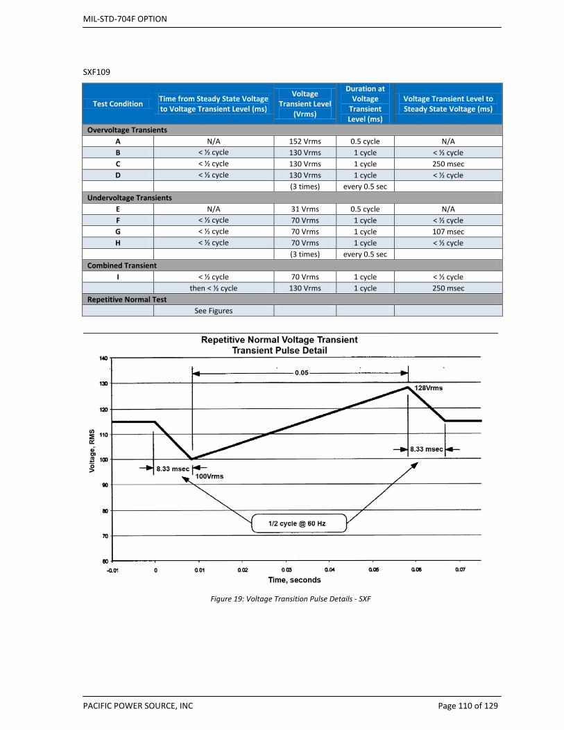
MIL-STD-704F OPTION
PACIFIC POWER SOURCE, INC Page 110 of 129
SXF109
Test Condition Time from Steady State Voltage to Voltage Transient Level (ms)
Voltage Transient Level
(Vrms)
Duration at Voltage
Transient Level (ms)
Voltage Transient Level to Steady State Voltage (ms)
Overvoltage Transients A N/A 152 Vrms 0.5 cycle N/A B < ½ cycle 130 Vrms 1 cycle < ½ cycle C < ½ cycle 130 Vrms 1 cycle 250 msec D < ½ cycle 130 Vrms 1 cycle < ½ cycle (3 times) every 0.5 sec
Undervoltage Transients E N/A 31 Vrms 0.5 cycle N/A F < ½ cycle 70 Vrms 1 cycle < ½ cycle G < ½ cycle 70 Vrms 1 cycle 107 msec H < ½ cycle 70 Vrms 1 cycle < ½ cycle (3 times) every 0.5 sec
Combined Transient I < ½ cycle 70 Vrms 1 cycle < ½ cycle
then < ½ cycle 130 Vrms 1 cycle 250 msec Repetitive Normal Test
See Figures
Figure 19: Voltage Transition Pulse Details - SXF

MIL-STD-704F OPTION
PACIFIC POWER SOURCE, INC Page 111 of 129
Figure 20: Repetitive Voltage transients.
SXF110
Test Condition Time from Steady
State Freq. to Freq. Transient Level
Freq. Transient Level Duration at Freq. Transient Level
Time from Freq. Transient Level to Steady State Freq.
Overfrequency Transients A 10 msec 61 Hz 0.5 cycle 10 msec B 10 msec 61 Hz 5 seconds 10 msec
Underfrequency Transients C 10 msec 59 Hz 0.5 cycle 10 msec D 10 msec 59 Hz 5 seconds 10 msec
Combined Transient E 10 msec 59 Hz 0.5 cycle 10 msec
then 10 msec 61 Hz 0.5 cycle 10 msec

MIL-STD-704F OPTION
PACIFIC POWER SOURCE, INC Page 112 of 129
SXF 201
Test Condition Steady State Voltage T fall Duration of Interrupt T rise A 115V < ½ cycle 50 msec < ½ cycle B 105V < ½ cycle 50 msec < ½ cycle C 125V < ½ cycle 50 msec < ½ cycle D 115V < ½ cycle 30 msec < ½ cycle E 105V < ½ cycle 30 msec < ½ cycle F 125V < ½ cycle 30 msec < ½ cycle G 115V < ½ cycle 10 msec < ½ cycle H 105V < ½ cycle 10 msec < ½ cycle I 125V < ½ cycle 10 msec < ½ cycle J 115V < ½ cycle 50 msec (repeated 3 times,
separated by 0.5 sec ) < ½ cycle
K 115V < ½ cycle 50 msec (followed by a normal voltage transient of 130 Vrms
for 30 msec and return to steady state voltage in 250
msec)
250 msec
L 115V < ½ cycle 50 msec (followed by a normal voltage transient of 70 Vrms for
1 cycle and return to steady state voltage in 107 msec)
107 msec
SXF301
Test Condition Voltage Frequency
Abnormal Limit 704F
A 115 59.5 Voltage 100 V B 115 60.5 ALSS C 100 60.0 Voltage 125 V D 100 59.5 AHSS E 100 60.5 Frequency 59.5 Hz F 125 60.0 ALSS G 125 59.5 Frequency 60.5 Hz H 125 60.5 AHSS

MIL-STD-704F OPTION
PACIFIC POWER SOURCE, INC Page 113 of 129
SXF302
Test Condition Time From Steady State Voltage to
Voltage Transient Level milliseconds
Voltage Transient Level Vrms
Duration at Voltage Transient Level
milliseconds
Time From Voltage Transient Level to
Steady State Voltage or Next Voltage Level
Overvoltage Transients A < ½ cycle 180 Vrms ½ cycle < ½ cycle B < ½ cycle 180 Vrms ½ cycle 1 cycle
then 147 Vrms Decreasing 1 cycle then 140 Vrms Decreasing 2.0 sec
115 Vrms C < ½ cycle 160 Vrms 1 cycle < ½ cycle D < ½ cycle 160 Vrms 1 cycle 1 cycle
then 140 Vrms Decreasing 2.0 sec
115 Vrms E < ½ cycle 180 Vrms ½ cycle < ½ cycle
(3 times) every 0.5 sec Undervoltage Transients
F < ½ cycle 50 Vrms ½ cycle < ½ cycle G < ½ cycle 50 Vrms ½ cycle 1 cycle
then 83 Vrms Increasing 1 cycle then 90 Vrms Increasing 2.0 sec
115 Vrms H < ½ cycle 70 Vrms 1 cycle < ½ cycle I < ½ cycle 70 Vrms 1 cycle 1 cycle
then 90 Vrms Increasing 2.0 sec 115 Vrms
J < ½ cycle 50 Vrms ½ cycle < ½ cycle (3 times) every 0.5 sec
Combined Transient K < ½ cycle 50 Vrms ½ cycle < ½ cycle
< ½ cycle 180 Vrms ½ cycle 1 cycle then 147 Vrms Decreasing 1 cycle then 140 Vrms Decreasing 2.0 sec
115 Vrms

MIL-STD-704F OPTION
PACIFIC POWER SOURCE, INC Page 114 of 129
SXF303
Test Condition Transition Time Transient Level Duration Transition2
Overfrequency Transients A ½ cycle 61 Hz ½ cycle ½ cycle B ½ cycle 61 Hz 6.968 secs ½ cycle
Underfrequency Transients C ½ cycle 50 Hz ½ cycle ½ cycle D ½ cycle 50 Hz 6.968 secs ½ cycle
Combined Transient E ½ cycle 50 Hz then ½ cycle ½ cycle
½ cycle 61 Hz ½ cycle ½ cycle
SXF401
Test Condition Voltage Frequency
Abnormal Limit 704F
A 115 59.5
Voltage 105V
B 115 60.5
ELSS
C 105 60.0
Voltage 125V
D 105 59.5
EHSS
E 105 60.5
Frequency 59.5Hz
F 125 60.0
ELSS
G 125 59.5
Frequency 60.5Hz
H 125 60.5
EHSS
SXF601
Test Condition Duration of Power Failure
A 100 msec
B 500 msec
C 2 secs
SXF603
Test Condition Phases Duration
Physical Means Prevention Verify/Check If Not: Reversed Phase Rotation N-A 30 mins
Correct Phase Rotation A-N 30 mins

MIL-STD-704F OPTION
PACIFIC POWER SOURCE, INC Page 115 of 129
9.4.6 LDC 28VDC LDC101
Test Plan Description DCR AC Setting Scaling
Stimulus: Apply 28Vdc 14.8Vac 1.99
Close CB or contactor to EUT and measure Inrush current
Allow EUT to warm up before taking additional measurements
Allow power to run for 15 mins.
Measure Inrush Current, all phases
Steady state voltage, current, power
Verify no half wave rectification is used
Current Harmonics / All phases using HAS option
Repeat For each EUT operating mode
LDC102
Test Condition Voltage DC DCR AC Setting Scaling
A 28 Vdc 14.8Vac 1.99
B 22 Vdc 11.8Vac 1.99
C 29 Vdc 15.3Vac 1.99
LDC103 DCR AC Setting = 14.8Vac, Scaling = 1.99
Test Condition Frequency of Voltage Distortion
Amplitude of Voltage Distortion Rev B, C, D
Amplitude of Voltage Distortion
Rev E, F
A 10 Hz 0.100 Vrms 0.100 Vrms
B 25 Hz 0.158 Vrms 0.158 Vrms
C 50 Hz 0.200 Vrms 0.223 Vrms
D 60 Hz 0.224 Vrms 0.245 Vrms
E 250 Hz 0.398 Vrms 0.500 Vrms
F 1 kHz 0.707 Vrms 1.000 Vrms
G 1.7 kHz 0.891 Vrms 1.000 Vrms
H 2 kHz 1.000 Vrms 1.000 Vrms
I 5 kHz 0.316 Vrms 1.000 Vrms
J 6.5 kHz 0.707 Vrms 0.707 Vrms
K 10 kHz 0.125 Vrms 0.500 Vrms

MIL-STD-704F OPTION
PACIFIC POWER SOURCE, INC Page 116 of 129
LDC104 - NOT SUPPORTED BY DCR
Test Condition Ripple Frequency Components MIL-STD-704B, C, D, E, & F Vrms
A 1200 Hz 0.80 Vrms
2400 Hz 0.16 Vrms
3600 Hz 0.26 Vrms
4800 Hz 0.08 Vrms
6000 Hz 0.13 Vrms
7200 Hz 0.04 Vrms
8400 Hz 0.06 Vrms
B 2400 Hz 0.80 Vrms
4800 Hz 0.16 Vrms
7200 Hz 0.26 Vrms
9600 Hz 0.08 Vrms
12000 Hz 0.13 Vrms
14400 Hz 0.04 Vrms
16800 Hz 0.06 Vrms
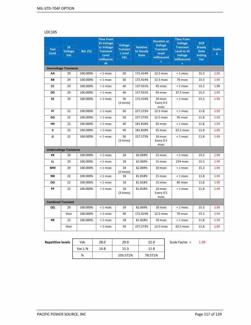
MIL-STD-704F OPTION
PACIFIC POWER SOURCE, INC Page 117 of 129
LDC105
Test Cond.
SS Voltage
Vdc Rel. (%)
Time From SS Voltage to Voltage Transient
Level millisecon
ds
Voltage Transient Level
Vdc
Relative to Steady
State
Duration at Voltage
Transient Level
milliseconds
Time From Voltage
Transient Level to SS
Voltage millisecond
s
DCR Steady State
Setting Vac
Scaling
Overvoltage Transients AA 29 100.000% < 1 msec 50 172.414% 12.5 msec < 1 msec 15.3 1.99
BB 29 100.000% < 1 msec 50 172.414% 12.5 msec 70 msec 15.3 1.99
CC 29 100.000% < 1 msec 40 137.931% 45 msec < 1 msec 15.3 1.99
DD 29 100.000% < 1 msec 40 137.931% 45 msec 37.5 msec 15.3 1.99
EE 29 100.000% < 1 msec 50 (3 times)
172.414% 10 msec Every 0.5
msec
< 1 msec 15.3 1.99
FF 22 100.000% < 1 msec 50 227.273% 12.5 msec < 1 msec 11.8 1.99
GG 22 100.000% < 1 msec 50 227.273% 12.5 msec 95 msec 11.8 1.99
HH 22 100.000% < 1 msec 40 181.818% 45 msec < 1 msec 11.8 1.99
II 22 100.000% < 1 msec 40 181.818% 45 msec 62.5 msec 11.8 1.99
JJ 22 100.000% < 1 msec 50 (3 times)
227.273% 10 msec Every 0.5
msec
< 1 msec 11.8 1.99
Undervoltage Transients
KK 29 100.000% < 1 msec 18 62.069% 15 msec < 1 msec 15.3 1.99
LL 29 100.000% < 1 msec 18 62.069% 15 msec 234 msec 15.3 1.99
MM 29 100.000% < 1 msec 18 (3 times)
62.069% 10 msec < 1 msec 15.3 1.99
NN 22 100.000% < 1 msec 18 81.818% 15 msec < 1 msec 11.8 1.99
OO 22 100.000% < 1 msec 18 81.818% 15 msec 85 msec 11.8 1.99
PP 22 100.000% < 1 msec 18 (3 times)
81.818% 10 msec Every 0.5
msec
< 1 msec 11.8 1.99
Combined Transient
QQ 29 100.000% < 1 msec 18 62.069% 10 msec < 1 msec 15.3 1.99
then 100.000% < 1 msec 50 172.414% 12.5 msec 70 msec 15.3 1.99
RR 22 100.000% < 1 msec 18 81.818% 10 msec < 1 msec 11.8 1.99
then < 1 msec 50 227.273% 12.5 msec 62.5 msec 11.8 1.99
Repetitive levels Vdc 28.0 29.0 22.0 Scale Factor = 1.99
Vac L-N 14.8 15.3 11.8
% 103.571% 78.571%
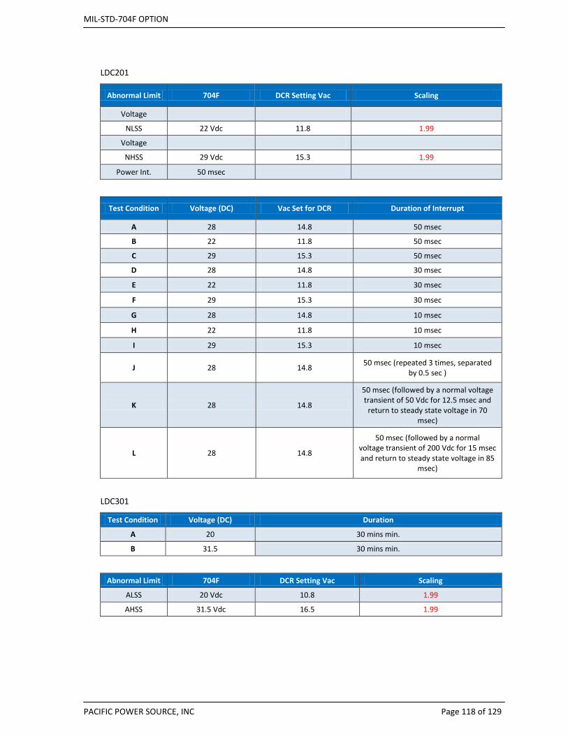
MIL-STD-704F OPTION
PACIFIC POWER SOURCE, INC Page 118 of 129
LDC201
Abnormal Limit 704F DCR Setting Vac Scaling
Voltage
NLSS 22 Vdc 11.8 1.99
Voltage
NHSS 29 Vdc 15.3 1.99
Power Int. 50 msec
Test Condition Voltage (DC) Vac Set for DCR Duration of Interrupt
A 28 14.8 50 msec
B 22 11.8 50 msec
C 29 15.3 50 msec
D 28 14.8 30 msec
E 22 11.8 30 msec
F 29 15.3 30 msec
G 28 14.8 10 msec
H 22 11.8 10 msec
I 29 15.3 10 msec
J 28 14.8 50 msec (repeated 3 times, separated by 0.5 sec )
K 28 14.8
50 msec (followed by a normal voltage transient of 50 Vdc for 12.5 msec and
return to steady state voltage in 70 msec)
L 28 14.8
50 msec (followed by a normal voltage transient of 200 Vdc for 15 msec and return to steady state voltage in 85
msec)
LDC301
Test Condition Voltage (DC) Duration
A 20 30 mins min.
B 31.5 30 mins min.
Abnormal Limit 704F DCR Setting Vac Scaling
ALSS 20 Vdc 10.8 1.99
AHSS 31.5 Vdc 16.5 1.99

MIL-STD-704F OPTION
PACIFIC POWER SOURCE, INC Page 119 of 129
LDC302
Test Conditio
n
Steady State
Voltage Vdc
Time From SS V to V Transient
Level msec
Voltage Transient Level Vdc
Relative to Steady
State
Duration at Voltage
Transient Level
Time From V Transient
Level to SS Voltage or
Next V Level
DCR AC Setting Scaling
Overvoltage Transients AAA 29 < 1 msec 50 172.414% 50 msec < 1 msec 15.3 1.99
BBB 29 < 1 msec 50 172.414% 50 msec 15 msec 15.3 1.99
then 45 155.172% decreasing 30 msec 15.3 1.99
then 40 137.931% decreasing 60 msec 15.3 1.99
then 35 120.690% decreasing 4.85 sec 15.3 1.99
then 30 103.448% decreasing 1 sec 15.3 1.99
then 29 100.000% 15.3 1.99
CCC 29 < 1 msec 50 (3 times)
172.414% 50 msec Every 0.5
sec
< 1 msec 15.3 1.99
DDD 22 < 1 msec 50 227.273% 50 msec < 1 msec 11.8 1.99
EEE 22 < 1 msec 50 227.273% 50 msec 15 msec 11.8 1.99
then 45 204.545% decreasing 30 msec 11.8 1.99
then 40 181.818% decreasing 60 msec 11.8 1.99
then 35 159.091% decreasing 4.85 sec 11.8 1.99
then 30 136.364% decreasing 8 sec 11.8 1.99
then 22 100.000% 11.8 1.99
FFF 22 < 1 msec 50 (3 times)
227.273% 50 msec Every 0.5
sec
< 1 msec 11.8 1.99
Undervoltage Transients GGG 29 < 1 msec 7 24.138% 50 msec < 1 msec 15.3 1.99 HHH 29 < 1 msec 7 24.138% 50 msec 15 msec 15.3 1.99
then 12 41.379% increasing 30 msec 15.3 1.99 then 17 58.621% increasing 60 msec 15.3 1.99 then 22 75.862% increasing 4.85 sec 15.3 1.99 then 28 96.552% increasing 1 sec 15.3 1.99 then 29 100.000% 15.3 1.99
III 29 < 1 msec 7 (3 times)
24.138% 50 msec Every 0.5
sec < 1 msec 15.3 1.99
JJJ 22 < 1 msec 7 31.818% 50 msec < 1 msec 11.8 1.99 KKK 22 < 1 msec 7 31.818% 50 msec 15 msec 11.8 1.99
then 12 54.545% increasing 30 msec 11.8 1.99 then 17 77.273% increasing 60 msec 11.8 1.99 then 22 100.000% 11.8 1.99
LLL 22 < 1 msec 7 (3 times)
31.818% 50 msec Every 0.5 < 1 msec 11.8 1.99
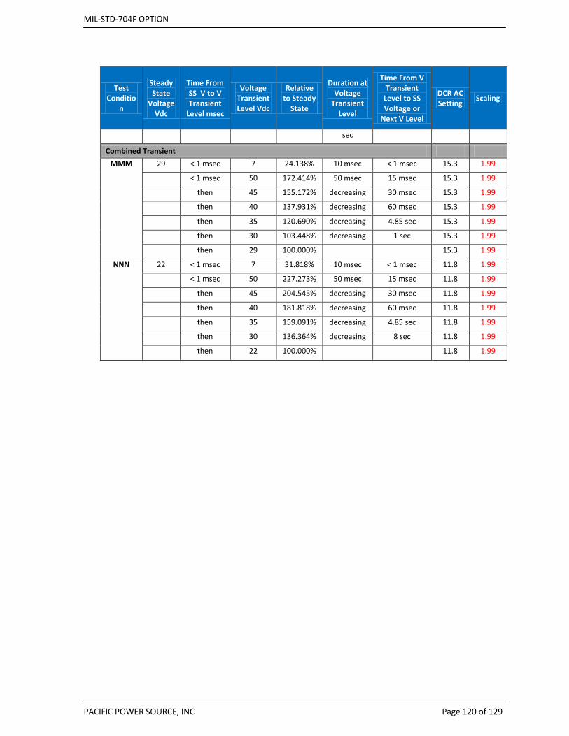
MIL-STD-704F OPTION
PACIFIC POWER SOURCE, INC Page 120 of 129
Test Conditio
n
Steady State
Voltage Vdc
Time From SS V to V Transient
Level msec
Voltage Transient Level Vdc
Relative to Steady
State
Duration at Voltage
Transient Level
Time From V Transient
Level to SS Voltage or
Next V Level
DCR AC Setting Scaling
sec
Combined Transient MMM 29 < 1 msec 7 24.138% 10 msec < 1 msec 15.3 1.99
< 1 msec 50 172.414% 50 msec 15 msec 15.3 1.99
then 45 155.172% decreasing 30 msec 15.3 1.99
then 40 137.931% decreasing 60 msec 15.3 1.99
then 35 120.690% decreasing 4.85 sec 15.3 1.99
then 30 103.448% decreasing 1 sec 15.3 1.99
then 29 100.000% 15.3 1.99
NNN 22 < 1 msec 7 31.818% 10 msec < 1 msec 11.8 1.99
< 1 msec 50 227.273% 50 msec 15 msec 11.8 1.99
then 45 204.545% decreasing 30 msec 11.8 1.99
then 40 181.818% decreasing 60 msec 11.8 1.99
then 35 159.091% decreasing 4.85 sec 11.8 1.99
then 30 136.364% decreasing 8 sec 11.8 1.99
then 22 100.000% 11.8 1.99
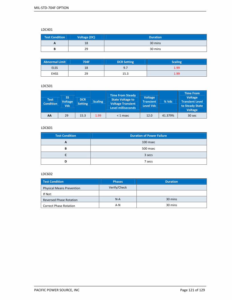
MIL-STD-704F OPTION
PACIFIC POWER SOURCE, INC Page 121 of 129
LDC401
Test Condition Voltage (DC) Duration
A 18 30 mins
B 29 30 mins
Abnormal Limit 704F DCR Setting Scaling
ELSS 18 9.7 1.99
EHSS 29 15.3 1.99
LDC501
Test Condition
SS Voltage
Vdc
DCR Setting Scaling
Time From Steady State Voltage to
Voltage Transient Level milliseconds
Voltage Transient Level Vdc
% Vdc
Time From Voltage
Transient Level to Steady State
Voltage
AA 29 15.3 1.99 < 1 msec 12.0 41.379% 30 sec
LDC601
Test Condition Duration of Power Failure
A 100 msec
B 500 msec
C 3 secs
D 7 secs
LDC602
Test Condition Phases Duration
Physical Means Prevention Verify/Check
If Not:
Reversed Phase Rotation N-A 30 mins
Correct Phase Rotation A-N 30 mins
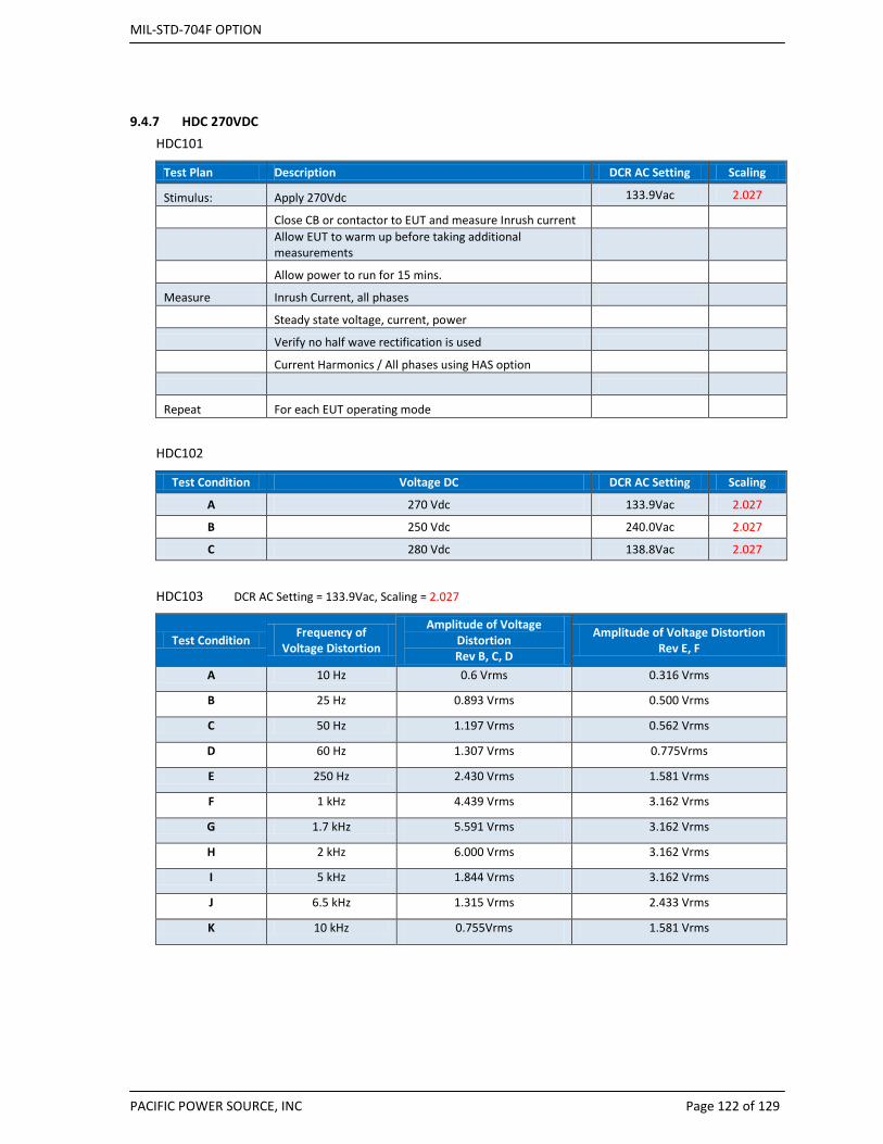
MIL-STD-704F OPTION
PACIFIC POWER SOURCE, INC Page 122 of 129
9.4.7 HDC 270VDC HDC101
Test Plan Description DCR AC Setting Scaling
Stimulus: Apply 270Vdc 133.9Vac 2.027
Close CB or contactor to EUT and measure Inrush current
Allow EUT to warm up before taking additional measurements
Allow power to run for 15 mins. Measure Inrush Current, all phases Steady state voltage, current, power Verify no half wave rectification is used Current Harmonics / All phases using HAS option
Repeat For each EUT operating mode
HDC102
Test Condition Voltage DC DCR AC Setting Scaling
A 270 Vdc 133.9Vac 2.027
B 250 Vdc 240.0Vac 2.027
C 280 Vdc 138.8Vac 2.027
HDC103 DCR AC Setting = 133.9Vac, Scaling = 2.027
Test Condition Frequency of Voltage Distortion
Amplitude of Voltage Distortion Rev B, C, D
Amplitude of Voltage Distortion Rev E, F
A 10 Hz 0.6 Vrms 0.316 Vrms
B 25 Hz 0.893 Vrms 0.500 Vrms
C 50 Hz 1.197 Vrms 0.562 Vrms
D 60 Hz 1.307 Vrms 0.775Vrms
E 250 Hz 2.430 Vrms 1.581 Vrms
F 1 kHz 4.439 Vrms 3.162 Vrms
G 1.7 kHz 5.591 Vrms 3.162 Vrms
H 2 kHz 6.000 Vrms 3.162 Vrms
I 5 kHz 1.844 Vrms 3.162 Vrms
J 6.5 kHz 1.315 Vrms 2.433 Vrms
K 10 kHz 0.755Vrms 1.581 Vrms

MIL-STD-704F OPTION
PACIFIC POWER SOURCE, INC Page 123 of 129
HDC104 - NOT SUPPORTED BY DCR
Test Condition Ripple Frequency Components MIL-STD-704B, C, D, E, & F Vrms A 1200 Hz 3.16 Vrms
2400 Hz 0.96 Vrms
3600 Hz 1.56 Vrms
4800 Hz 0.48 Vrms
6000 Hz 0.78 Vrms
7200 Hz 0.24 Vrms
8400 Hz 0.36 Vrms
B 2400 Hz 3.16 Vrms
4800 Hz 0.96 Vrms
7200 Hz 1.56 Vrms
9600 Hz 0.48 Vrms
12000 Hz 0.78 Vrms
14400 Hz 0.24 Vrms
16800 Hz 0.36 Vrms
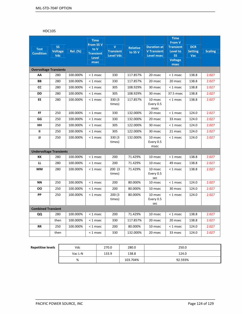
MIL-STD-704F OPTION
PACIFIC POWER SOURCE, INC Page 124 of 129
HDC105
Test Condition
SS Voltage
Vdc Rel. (%)
Time From SS V
to V Transient
Level msec
V Transient Level Vdc
Relative to SS V
Duration at V Transient Level msec
Time From V
Transient Level to
SS Voltage
msec
DCR Setting
Vac Scaling
Overvoltage Transients AA 280 100.000% < 1 msec 330 117.857% 20 msec < 1 msec 138.8 2.027
BB 280 100.000% < 1 msec 330 117.857% 20 msec 20 msec 138.8 2.027
CC 280 100.000% < 1 msec 305 108.929% 30 msec < 1 msec 138.8 2.027
DD 280 100.000% < 1 msec 305 108.929% 30 msec 37.5 msec 138.8 2.027
EE 280 100.000% < 1 msec 330 (3 times)
117.857% 10 msec Every 0.5
msec
< 1 msec 138.8 2.027
FF 250 100.000% < 1 msec 330 132.000% 20 msec < 1 msec 124.0 2.027
GG 250 100.000% < 1 msec 330 132.000% 20 msec 33 msec 124.0 2.027
HH 250 100.000% < 1 msec 305 122.000% 30 msec < 1 msec 124.0 2.027
II 250 100.000% < 1 msec 305 122.000% 30 msec 21 msec 124.0 2.027
JJ 250 100.000% < 1 msec 330 (3 times)
132.000% 10 msec Every 0.5
msec
< 1 msec 124.0 2.027
Undervoltage Transients KK 280 100.000% < 1 msec 200 71.429% 10 msec < 1 msec 138.8 2.027
LL 280 100.000% < 1 msec 200 71.429% 10 msec 49 msec 138.8 2.027
MM 280 100.000% < 1 msec 200 (3 times)
71.429% 10 msec Every 0.5
sec
< 1 msec 138.8 2.027
NN 250 100.000% < 1 msec 200 80.000% 10 msec < 1 msec 124.0 2.027
OO 250 100.000% < 1 msec 200 80.000% 10 msec 30 msec 124.0 2.027
PP 250 100.000% < 1 msec 200 (3 times)
80.000% 10 msec Every 0.5
sec
< 1 msec 124.0 2.027
Combined Transient QQ 280 100.000% < 1 msec 200 71.429% 10 msec < 1 msec 138.8 2.027
then 100.000% < 1 msec 330 117.857% 20 msec 20 msec 138.8 2.027
RR 250 100.000% < 1 msec 200 80.000% 10 msec < 1 msec 124.0 2.027
then < 1 msec 330 132.000% 20 msec 33 msec 124.0 2.027
Repetitive levels Vdc 270.0 280.0 250.0
Vac L-N 133.9 138.8 124.0
% 103.704% 92.593%

MIL-STD-704F OPTION
PACIFIC POWER SOURCE, INC Page 125 of 129
HDC201
Abnormal Limit 704F DCR Setting Vac Scaling
Voltage
NLSS 250 Vdc 124.0 2.027
Voltage
NHSS 280 Vdc 138.8 2.027
Power Int. 50 msec
Test Condition Voltage (DC) Vac Set for DCR Duration of Interrupt
A 270 133.9 50 msec
B 250 124.0 50 msec
C 280 138.8 50 msec
D 270 133.9 30 msec
E 250 124.0 30 msec
F 280 138.8 30 msec
G 270 133.9 10 msec
H 250 124.0 10 msec
I 280 138.8 10 msec
J 270 133.9 50 msec (repeated 3 times, separated by 0.5 sec )
K 270 133.9 50 msec (followed by a normal voltage transient of 330 Vdc for 20 msec and
return to steady state voltage in 20 msec)
L 270 133.9 50 msec (followed by a normal
voltage transient of 200 Vdc for 15 msec and return to steady state voltage in 85
msec)
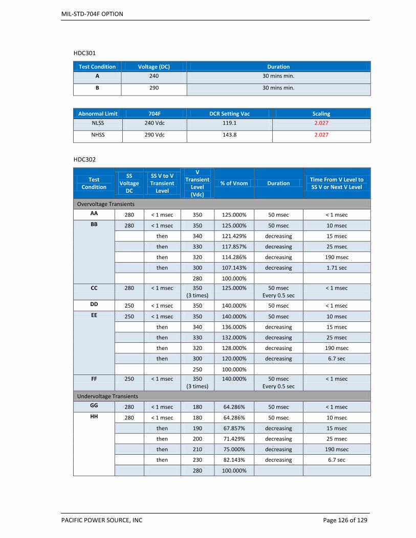
MIL-STD-704F OPTION
PACIFIC POWER SOURCE, INC Page 126 of 129
HDC301
Test Condition Voltage (DC) Duration A 240 30 mins min.
B 290 30 mins min.
Abnormal Limit 704F DCR Setting Vac Scaling NLSS 240 Vdc 119.1 2.027
NHSS 290 Vdc 143.8 2.027
HDC302
Test Condition
SS Voltage
DC
SS V to V Transient
Level
V Transient
Level (Vdc)
% of Vnom Duration Time From V Level to SS V or Next V Level
Overvoltage Transients AA 280 < 1 msec 350 125.000% 50 msec < 1 msec BB 280 < 1 msec 350 125.000% 50 msec 10 msec
then 340 121.429% decreasing 15 msec
then 330 117.857% decreasing 25 msec
then 320 114.286% decreasing 190 msec
then 300 107.143% decreasing 1.71 sec
280 100.000% CC 280 < 1 msec 350
(3 times) 125.000% 50 msec
Every 0.5 sec < 1 msec
DD 250 < 1 msec 350 140.000% 50 msec < 1 msec EE 250 < 1 msec 350 140.000% 50 msec 10 msec
then 340 136.000% decreasing 15 msec
then 330 132.000% decreasing 25 msec
then 320 128.000% decreasing 190 msec
then 300 120.000% decreasing 6.7 sec
250 100.000% FF 250 < 1 msec 350
(3 times) 140.000% 50 msec
Every 0.5 sec < 1 msec
Undervoltage Transients GG 280 < 1 msec 180 64.286% 50 msec < 1 msec HH 280 < 1 msec 180 64.286% 50 msec 10 msec
then 190 67.857% decreasing 15 msec
then 200 71.429% decreasing 25 msec
then 210 75.000% decreasing 190 msec
then 230 82.143% decreasing 6.7 sec
280 100.000%
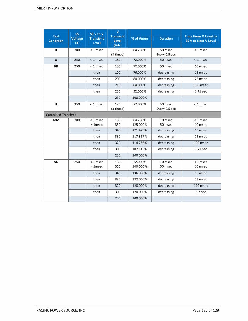
MIL-STD-704F OPTION
PACIFIC POWER SOURCE, INC Page 127 of 129
Test Condition
SS Voltage
DC
SS V to V Transient
Level
V Transient
Level (Vdc)
% of Vnom Duration Time From V Level to SS V or Next V Level
II 280 < 1 msec 180 (3 times)
64.286% 50 msec Every 0.5 sec
< 1 msec
JJ 250 < 1 msec 180 72.000% 50 msec < 1 msec
KK 250 < 1 msec 180 72.000% 50 msec 10 msec
then 190 76.000% decreasing 15 msec
then 200 80.000% decreasing 25 msec
then 210 84.000% decreasing 190 msec
then 230 92.000% decreasing 1.71 sec
250 100.000%
LL 250 < 1 msec 180 (3 times)
72.000% 50 msec Every 0.5 sec
< 1 msec
Combined Transient MM 280 < 1 msec
< 1msec 180 350
64.286% 125.000%
10 msec 50 msec
< 1 msec 10 msec
then 340 121.429% decreasing 15 msec
then 330 117.857% decreasing 25 msec
then 320 114.286% decreasing 190 msec
then 300 107.143% decreasing 1.71 sec
280 100.000%
NN 250 < 1 msec < 1msec
180 350
72.000% 140.000%
10 msec 50 msec
< 1 msec 10 msec
then 340 136.000% decreasing 15 msec
then 330 132.000% decreasing 25 msec
then 320 128.000% decreasing 190 msec
then 300 120.000% decreasing 6.7 sec
250 100.000%
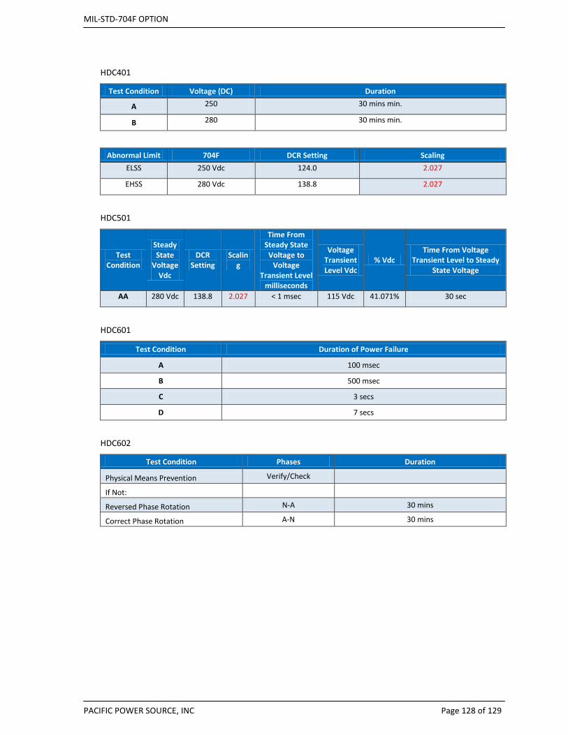
MIL-STD-704F OPTION
PACIFIC POWER SOURCE, INC Page 128 of 129
HDC401
Test Condition Voltage (DC) Duration
A 250 30 mins min.
B 280 30 mins min.
Abnormal Limit 704F DCR Setting Scaling ELSS 250 Vdc 124.0 2.027
EHSS 280 Vdc 138.8 2.027
HDC501
Test Condition
Steady State
Voltage Vdc
DCR Setting
Scaling
Time From Steady State
Voltage to Voltage
Transient Level milliseconds
Voltage Transient Level Vdc
% Vdc Time From Voltage
Transient Level to Steady State Voltage
AA 280 Vdc 138.8 2.027 < 1 msec 115 Vdc 41.071% 30 sec
HDC601
Test Condition Duration of Power Failure
A 100 msec
B 500 msec
C 3 secs
D 7 secs
HDC602
Test Condition Phases Duration
Physical Means Prevention Verify/Check
If Not:
Reversed Phase Rotation N-A 30 mins
Correct Phase Rotation A-N 30 mins
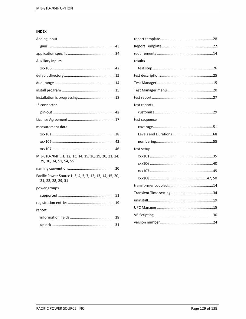
MIL-STD-704F OPTION
PACIFIC POWER SOURCE, INC Page 129 of 129
INDEX
Analog Input
gain .................................................................. 43
application specific .............................................. 34
Auxiliary Inputs
xxx106 .............................................................. 42
default directory .................................................. 15
dual-range ........................................................... 14
install program .................................................... 15
installation is progressing .................................... 18
J5 connector
pin-out ............................................................. 42
License Agreement .............................................. 17
measurement data
xxx101 .............................................................. 38
xxx106 .............................................................. 43
xxx107 .............................................................. 46
MIL-STD-704F .. 1, 12, 13, 14, 15, 16, 19, 20, 21, 24, 29, 30, 34, 51, 54, 55
naming convention .............................................. 20
Pacific Power Source 1, 3, 4, 5, 7, 12, 13, 14, 15, 20, 21, 22, 28, 29, 31
power groups
supported ........................................................ 51
registration entries .............................................. 19
report
information fields ............................................ 28
unlock .............................................................. 31
report template .................................................... 28
Report Template .................................................. 22
requirements ....................................................... 14
results
test step ........................................................... 26
test descriptions ................................................... 25
Test Manager ....................................................... 15
Test Manager menu ............................................. 20
test report ............................................................ 27
test reports
customize ......................................................... 29
test sequence
coverage ........................................................... 51
Levels and Durations ........................................ 68
numbering ........................................................ 55
test setup
xxx101 .............................................................. 35
xxx106 .............................................................. 40
xxx107 .............................................................. 45
xxx108 ........................................................ 47, 50
transformer coupled ............................................ 14
Transient Time setting ......................................... 34
uninstall ................................................................ 19
UPC Manager ....................................................... 15
VB Scripting .......................................................... 30
version number .................................................... 24