MIL-S-17000N
89
MIL-S-17000N(SH) 2 May 1983 . — SUPERSEDING MIL-S-17000M(SH) 30 April 1980 MIL-S-15001G(SHIPS) 28 September 1965 (See 6.7) MILITARY SPECIFICATION SWITCHING EQUIPMENT, COMBAT SYSTEM, COMMAND AND CONTROL, FIRE CONTROL, AND INTERIOR COMMUNICATION GENERAL SPECIFICATION FOR This specification is approved for use by the Naval Sea Systems Command Department of the Navy, and is available for use by all Departments and Agencies of the Department of Defense. 1. SCOPE 101 Scope. This specification covers the general design requirements, operating conditions, and tests for Naval shipboard switching equipment (see 6.1). 1.2 Classification. Switching equipment consists of switchboards and control indicators. Detail design requirements will be specified for each acquisition of this equipment to suit the requirements of the specific control systems. 1.2.1 Switchboards. Switchboards shall be of the following types as specified (see 3.1 and 6.2.1): Type II - Switchboard, surface ship, connected) . Type III - Switchboard, surface ship, connected). Type IV - Switchboard, surface ship, Type V - Switchboard, surface ship, Type VI - Switchboard, surface ship, sections, (terminal board Type VII - Switchboard, surface ship, (terminal board connected). deck-mounted, (terminal board bulkhead-mounted (terminal board deck-mounted, (plug connected). bulkhead-mounted, (plug connected). deck-mounted, two separate and plug connected). deck-mounted, power distribution, Beneficial comments (recommendations, additions, deletions) and any pertinent data which may be of use in improving this document should be addressed to: Commander, Naval Sea Systems Command, SEA 55Z3, Department of the Navy, Washington, DC 20362 by using the self-addressed Standardization Document Improvement Proposal (DD Form 1426) appearing at the end of this document or by letter. FSC 1290 Downloaded from http://www.everyspec.com on 2010-12-22T18:52:36.
-
Upload
steve93030 -
Category
Documents
-
view
112 -
download
2
Transcript of MIL-S-17000N
MIL-S-17000N(SH)2 May 1983. —SUPERSEDINGMIL-S-17000M(SH)30 April 1980MIL-S-15001G(SHIPS)28 September 1965(See 6.7)
MILITARY SPECIFICATION
SWITCHING EQUIPMENT, COMBAT SYSTEM, COMMANDAND CONTROL, FIRE CONTROL, AND INTERIOR COMMUNICATION
GENERAL SPECIFICATION FOR
This specification is approved for use by the Naval Sea Systems CommandDepartment of the Navy, and is available for use by all Departments andAgencies of the Department of Defense.
1. SCOPE
101 Scope. This specification covers the general design requirements,operating conditions, and tests for Naval shipboard switching equipment (see 6.1).
1.2 Classification. Switching equipment consists of switchboards andcontrol indicators. Detail design requirements will be specified for eachacquisition of this equipment to suit the requirements of the specific controlsystems.
1.2.1 Switchboards. Switchboards shall be of the following types asspecified (see 3.1 and 6.2.1):
Type II - Switchboard, surface ship,connected) .
Type III - Switchboard, surface ship,connected).
Type IV - Switchboard, surface ship,Type V - Switchboard, surface ship,Type VI - Switchboard, surface ship,
sections, (terminal boardType VII - Switchboard, surface ship,
(terminal board connected).
deck-mounted, (terminal board
bulkhead-mounted (terminal board
deck-mounted, (plug connected).bulkhead-mounted, (plug connected).deck-mounted, two separateand plug connected).deck-mounted, power distribution,
Beneficial comments (recommendations, additions, deletions) and any pertinentdata which may be of use in improving this document should be addressed to:Commander, Naval Sea Systems Command, SEA 55Z3, Department of the Navy,Washington, DC 20362 by using the self-addressed Standardization DocumentImprovement Proposal (DD Form 1426) appearing at the end of this documentor by letter.
FSC 1290
Downloaded from http://www.everyspec.com on 2010-12-22T18:52:36.
MIL-S-17000N(SH)
Type VIII -
Type IX -
Type X -
Type XI -
Type XII -
1.2.2 Switching
Switchboard, surface ship, deck-mounted, digital switching,(plug connected).
Switchboard, submarine, (as specified in the acquisitiontechnical data package).
Switchboard, surface ship, deck-mounted, interior communi-cation, (terminal board connected).
Switchboard, surface ship, bulkhead-mounted, interiorcommunication, (terminal board connected).
Switchboard, submarine, deck-mounted, command and control(plug connected).
control. Control indicator shall be as specified (see 3.1and 6.2.1).
2. APPLICABLE DOCUMENTS
2.1 Government documents.
2.1.1 Specifications, standards, and handbooks. Unless otherwise speci-fied, the following specifications, standards, and handbooks of the issue listedin that issue of the Department of Defense Index of Specifications and Standards(DoDISS) specified in the solicitation form a part of this specification to theextent specified herein.
SPECIFICATIONS
FEDERALL-P-387 -
QQ-A-200 -
QQ-A-225 -
QQ-A-250 -
QQ-A-591 -QQ-A-596 -
QQ-A-601 -QQ-C-320 -QQ-C-591 -
QQ-W-423 -MMM-A-121 -
PPP-B-601 -PPP-B-621 -
Plastic Sheet, Laminated, Thermosetting (for Designa-tion Plates).
Aluminum Alloy, Bar, Rod, Shapes, Structural Shapes,Tube and Wire, Extruded: General Specification for.
Aluminum and Aluminum Alloy Bar, Rod, Wire, or SpecialShapes; Rolled, Drawn, or Cold Finished; GeneralSpecification for.
Aluminum and Aluminum Alloy Plate and Sheet: GeneralSpecification for.
Aluminum Alloy Die Castings.Aluminum Alloy Permanent and Semipermanent MoldCastings.
Aluminum Alloy Sand Castings.Chromium Plating (Electrodeposited).Copper-Silicon, Copper-Zinc-Silicon, and Copper-Nickel-Silicon Alloys: Rod, Wire, Shapes, Forgings,and Flat Products (Flat Wire, Strip, Sheet, Bar,and Plate).
Wire, Steel, Corrosion-Resisting.Adhesive, Bonding Vulcanized Synthetic Rubber toSteel.
Boxes, Wood, Cleated-Plywood.Boxes, Wood, Nailed and Lock-Corner.
2
Downloaded from http://www.everyspec.com on 2010-12-22T18:52:36.
MIL-S-17000N(SH)
MILITARYMIL-C-5/l -MIL-C-17 -
MIL-T-27 -
MIL-P-116 -MIL-I-631 -
MIL-S-901 -
MIL-C-915 -
MIL-C-915/28 -MIL-C-915/29 -MIL-c-915/30 -MIL-c-915/31 -MIL-C-915/60 -
MIL-C-915/63 -MIL-I-1361 -
MIL-C-2212 -
MIL-L-3661 -
MIL-L-3661/60 -MIL-L-3661/61 -MIL-L-3661/62 -
MIL-L-3661/63 -MIL-L-3661/64-MIL-L-3661/65 -MIL-S-3950
MIL-C-5015
MIL-B-5423
MIL-P-5425MIL-C-5541
MIL-B-5687
MIL-R-5757MIL-R-6106
MIL-L-6363
MIL-T-7928
Capacitors, Fixed, Mica Dielectric, Style CM 15.Cables, Radio Frequency, Flexible and Semirigid,General Specification for.
Transformers and Inductors (Audio, Power, and High-Power Pulse), General Specification for.
Preservation, Methods of.Insulation, Electrical, Synthetic-Resin Composi-tion, Nonrigid.
Shock Tests, H.I. (High-Impact); Shipboard Machin-ery, Equipment and Systems, Requirements for.
Cable and Cord Electrical, For Shipboard UseGeneral Specifications for.
Cable, Electrical, 1000 Volts, Type SSGU.Cable, Electrical, 1000 Volts, Type DSGU.Cable, Electrical, 1000 Volts, Type TSGU.Cable, Electrical, 1000 Volts, Type FSGU.Cable, Electrical, 600 Volts, Types 2SJ, 3SJ, and4SJ.
Cable, Electrical, 300 Volts, Type 2U.Instrument Auxiliaries, Electrical Measuring:Shunts, Resistors, and Transformers*
Controllers, Electric Motor A.C. or D.C., andAssociated Switching Devices.
Lampholders, Indicator Lights, Indicator-LightHousings, and Indicator-Light Lenses, GeneralSpecification for.
Lights, Indicator (Transformer), Style LH93.Lampholder, Lights, Indicator (Housing), Style LH94.Lampholder, Lights, Indicator (Housing), Style LH95(for D.C. Applications).
Lampholder, Lights, Indicator (Housing), Style LH96.Lampholder, Lights, Indicator (Housing), Style LH97.Lampholder, Lights, Indicator (Housing), Style LH98.Switches, Toggle, Environmentally Sealed, GeneralSpecification for.
Connectors, Electrical, Circular Threaded, AN Type,General Specification for.
Boots , Dust and Water Seal (for Toggle and Push-button Switches, Circuit Breakers, and Rotary-Actuated Parts), General Specification for.
Plastic Sheet, Acrylic, Heat Resistant.Chemical Conversion Coatings on Aluminum andAluminum Alloys.
Bearings, Sleeve; Washers, Thrust; Sintered, MetalPowder, Oil-Impregnated.
Relays, Electromagnetic, General Specification for.Relays, Electromagnetic, Including EstablishingReliability (ER Types), General Specification for.
Lamps, Incandescent, Aviation Service, GeneralSpecification for.
Terminals, Lug: Splices, Conductor: Crimp Style,Copper, General Specification for.
3
Downloaded from http://www.everyspec.com on 2010-12-22T18:52:36.
MIL-S-17000N(SH)
MIL-T-7928/l
MIL-T-7928/2
MIL-T-7928/3
MIL-T-7928/5
MIL-W-8604
MIL-S-8805
MIL-S-12883
MIL-P-13949
MIL-P-15024
MIL-P-15024/5MIL-L-15098
- Terminals, Lug and Splices, Conductor, CrimpStyle, Copper Terminal, Lug, Crimp Style,Copper, Insulated, Ring Tongue, For Thin WallWire, Type 11 Class I For 105°C Total ConductorTemperature.
- Terminals, Lug and Splices, Conductor, CrimpStyle, Copper, Insulated, Rectangular Tongue,For Thin Wall Wire, Type II Class 1 for 105°CTotal Conductor Temperature.
- Splice, Conductor, Electric, (Permanent, Crimp-Style, Copper, Insulated, Type II, Class 1).
- Terminals, Lug and Splices, Conductor, CrimpStyle, Splice, Electric, (Permanent, Type II,Class 1) For 105°C Total Conductor Temperature.
- Welding, Fusion; Aluminum A11oys; process andPerformance of.
- Switches and Switch Assemblies, Sensitive, andPush (Snap Action), General Specification for.
- Sockets and Accessories for Plug-in ElectronicComponents, General Specification for.
- Plastic Sheet, Laminated, Metal Clad (For PrintedWiring Boards), General Specification for.
- Plates, Tags and Bands for Identification ofEquipment.
- Plates, Identification.- Lamps. Glow General Specification for.
MIL-L-15098/11 - Lamps, Glow, Indicator, Types C7A, C9A, AIG, andAIH.
MIL-F-15160/3 - Fuses; Instrument, Power, and Telephone (Non-Indicating), Style F03.
MIL-F-15160/77 - Fuses (Indicating), Style F77A.MIL-S-15291 - Switches, Rotary, Snap Action and Detent/Spring
Return Action General Specification for.MIL-A-15303 - Audible Signals: Alarms, Bells, Buzzers, Horns,
Sirens, and Electronic Shipboard.MIL-M-15562 - Matting or Sheet, Floor Covering, Insulating
for High Voltage Application.MIL-M-16125 - Meters, Electrical, Frequency.MIL-T-16366 - Terminals, Electrical Lug and Conductor Splices,
Crimp-Style.MIL-F-16377 - Fixtures, Lighting; and Associated Parts; Ship-
board Use, General Specification for.MIL-F-16377/4 - Light, Fluorescent, Detail Lighting for Secretary
Bureau, 8 Watts, 115 Volts, 60 Hertz AlternatingCurrent, Symbol 142.2.
MIL-F-16377/46 - Fixtures, Light, Ballast Box, for One 8 WattFluorescent Lamp, T-5, Symbol 514.
MIL-E-16400 - Electronic, Interior Communication and NavigationEquipment, Naval Ship and Shore: GeneralSpecification fOr.
MIL-W-L6878 - Wire, Insulated, General Specification for.MIL-W-16878/17 - Wire, Electrical, Polyvinyl Chloride (PVC) Insu-
lated, 105°C, 600 Volts, Polyamide Jacket.
4
Downloaded from http://www.everyspec.com on 2010-12-22T18:52:36.
MIL-S-17000N(SH)
MIL-W-16878/18 -
MIL-W-16878/19 -
MIL-R-16999 -MIL-C-17361 -
MIL-C-17588 -
MIL-S-17773 -
MIL-S-18396 -MIL-F-19207 -
MIL-F-19207/l -
MIL-F-19207/18 -
MIL-F-19207/38 -
MIL-A-21180 -MIL-S-21604 -
MIL-S-21604/2 -
MIL-E-22118 -MIL-S-22473 -
MIL-S-22710 -
MIL-S-22885 -
MIL-I-23053 -
MIL-I-23053/5 -
MIL-M-23167 -
MIL-S-23190 -
MIL-C-24105 -MIL-S-24187 -
MIL-S-24187/l -
MIL-S-24187/2 -
MIL-S-24187/3 -
MIL-S-24187/4 -
Wire, Electrical, Polyvinyl Chloride (PVC) Insu-lated, 105°C, 1000 Volts, Polyamide Jacket.
Wire, Electrical, Polyvinyl Chloride (PVC) Insu-lated, 105°C, 3000 Volts, Polyamide Covering.
Remote-Operated Switch Assemblies.Circuit Breakers, Air, Electric, InsulatedHousing (Shipboard Use).
Circuit Breakers (Automatic-ALB-1) and Switch,Toggle (Circuit Breaker, Non Automatic-NLB-l),Air, Insulated Housing, 125 Volts and Below,A.C. and D.C., (Naval Shipboard Use).Switching Unit, Power Transfer (Bus Transfer)(Naval Shipboard Use).
Switches, Meter and Control, Naval Shipboard.Fuseholders, Extractor Post Type, Blown FuseIndicating and Nonindicating General Specifi-cation for.
Fuseholders,Indicating,
Fuseholders,Indicating,
Fuseholders,Indicating,
Extractor Post Type, Blown FuseType FHL1OU.Extractor Post Type, Blown FuseType FHL29G.Extractor Post Type, Blown FuseType FHL57G.
Aluminum-Alloy castings, High strength”Switches, Rotary, Multipole and Selector;General Specification for.Switch, Rotary, Multipole and Selector, 5 Ampere,Style JK.
Enamel, Electrical-Insulating.Sealing, Locking, and Retaining Compounds;Single-Component.
Switches, Rotary (Printed Circuits), (Thumbwheeland Pushbutton), General Specification for.
Switch, Push Button, Illuminated, General Specifi-cation for.
Insulation Sleeving, Electrical, Heat Shrinkable,General Specification for.
Insulation Sleeving, Electrical, Heat Shrinkable,Polyolefin, Flexible, Crosslinked.
Meter, Frequency, Expanded Scale SwitchboardType (Naval Shipboard Use).
Straps, Clamps, and Mounting Hardware, Plasticfor Cable Harness Tying and Support.
Converters, Synchro Signal (Panel Mounted).Switch Assemblies, Linear Movement, Manual andRemote Operation, General Specification for.Switch Assemblies, Linear Movement, Manual andRemote Operation, Style LS*Switch Assemblies, Linear Movement, ManualOperation, Style BLS.
Switch Assemblies, Linear Movement, ManualOperation, Style CLS.Switch Assemblies, Linear Movement, Manual andRemote Operation, Style DLS.
5
Downloaded from http://www.everyspec.com on 2010-12-22T18:52:36.
MIL-S-17000N(SH)
MIL-S-24187/5 - Switch Assemblies, Linear Movement, ManualOperation, Style JLS.
MIL-S-24187/6 - Switch Assemblies, Linear Movement, Manualand Remote Operation, Snap-Action, Style SLS.
MIL-S-24187/7 - Switch Assemblies, Linear Movement, ManualOperation, Style KLS.
MIL-T-24558 - Terminal Boxes, Connection for Electrical andElectronic Systems, General Specification for.
MIL-T-24558/18 - Terminal Boxes, Connection, Submersible (15-Foot), 600 Volts, 4-Terminal, 8-Wire, Symbols400.1 and 400.4, 4-Terminal, 12-Wire, Symbols400.2 and 400.3.
MIL-B-26195 - Boxes, Wood-Cleated, Skidded, Load-BearingBase. .
MIL-C-28731 - Connectors, Electrical, Rectangular, RemovableContact, Formed Blade, Fork Type (for Rack andPanel and Other Applications), General Speci-fication for.
MIL-C-28731/23 - Connector, Electrical, Contact, Fork Type,Removable, Double Wire Crimp.
NIL-C-28748 - Connectors, Electrical, Rectangular, Rack andPanel, Solder Type and Crimp Type ContactsGeneral Specification for.
MIL-C-28748/9 - Connectors, Electrical, Rectangular, Rack andPanel, Polarized Center Jackscrew or GuidepinStyle, Crimp Type Removable Pin Contacts, Size 16.
MIL-C-28748/10 - Connectors, Electrical, Rectangular, Rack andPanel, Polarized Center Jackscrew or GuidepinStyle, Crimp Type Removable Socket Contacts,Size 16.
MIL-C-39012 - Connectors, Coaxial, Radiofrequency; GeneralSpecification for.
MIL-C-39029 - Contacts, Electrical Connector, General Specifi-cation for.
MIL-P-5511O - Printed-Wiring Boards.MIL-T-55164 - Terminal Boards, Molded, Barrier, Screw and Stud
Types, and Associated Accessories, GeneralSpecification for.
MIL-M-81531 - Marking of Electrical Insulating Materials.
(See Supplement 1 for list of associated specification sheets.)
STANDARDS
FEDERALFED-STD-595 - Colors.
MILITARYMIL-STD-104 - Limits for Electrical Insulation Color.MIL-STD-108 - Definitions of and Basic Requirements for Enclo-
sures for Electric and Electronic Equipment.MIL-STD-129 - Marking for Shipment and Storage.
6
Downloaded from http://www.everyspec.com on 2010-12-22T18:52:36.
MIL-S-17000N(SH)
MIL-STD-167-1 - Mechanical Vibrations of Shipboard Equipment(Type I - Environmental and Type II - InternallyExcited).
MIL-STD-242 - Electronic Equipment Parts Selected Standards.MIL-STD-275 - Printed Wiring for Electronic Equipment.MIL-STD-454 - Standard General Requirements for Electronic
Equipment.MIL-STD-794 - Parts and Equipment, Procedures for Packaging of.MIL-STD-889 - Dissimilar Metals.MIL-STD-965 - Parts Control Program.MIL-STD-1303 - Painting of Naval Ordnance Equipment.MIL-STD-1310 - Shipboard Bonding, Grounding, and Other Techniques
for Electromagnetic Compatibility and Safety.MIL-STD-1399, - Interface Standard for Shipboard Systems, AmbientSection 204 Air Conditions in Surface Ship Compartments.
DOD-STD-1399, - Interface Standard for Shipboard Systems, ElectricSection 300 Power, Alternating Current (Metric).
MIL-STD-1657 - Switching Equipment, Combat System, Command and
MS3105MS3187
MS3402
MS3406
MS3415MS3417
MS15571
MS15572
MS15573
MS17143
MS18121
MS21981
MS24140
MS24168
MS25181
MS25237
MS25274
Control, and Fire Control and Fire Control Require-ments for.
- Connector, Receptacle, Electric Dummy Stowage.- Plug, End Seal, For MIL-C-26482, MIL-C-5015,
MIL-C-81703 and MIL-C-83723 Electrical Connectors.- Connectors, Receptacle, Electric, BOX Mounting,
Front Release, Crimp Contact, AN Type.- Connectors, Plug, Electric, Front Release, Crimp
Contact AN Type.- Clamps, Strain Relief, 45°, for Electric Connectors.- Clamps, Strain Relief, Straight, for Electric
Connectors.- Lamps, Incandescent, T-3-l/4, Miniature Bayonet,
Single Contact.- Lamps, Incandescent, G-4-l/2, Miniature Bayonet,
Single Contact.- Lamp, Incandescent, G-3-l/2, Miniature Bayonet
Base, Single Contact.- Terminal, Lug, Crimp Style, copper, Insulated,
Rectangular Tongue, Type II, Class 1 for 105°CTotal Conductor Temperature.
- Ferrules, Outer, Insulated, Shield TerminatingType II, Two-Piece, Class 1, for Shielded Cable.
- Ferrule, Inner, Uninsulated, Shield Terminating,Type I, Two-Piece, Class 1, for Shielded Cable.
- Relay, SO Amp, IPST, N.O. Type 1, HermeticallySealed.
- Relay, 100 Amp, 3PST, N.O. Type I, HermeticallySealed.
- Splice, Electric, permanent, Crimp Style, CoPPer>Insulated, Type 11, Class 1.
- Lamp, Incandescent, Single Contact Midget FlangedBase (T-1-3/4 Bulb):
- Cap, Electrical (Wire End, Crimp Style, Type II,Class 1) for 105°C Total Conductor Temperature.
7
Downloaded from http://www.everyspec.com on 2010-12-22T18:52:36.
MIL-S-17000N(SH)
MS27400 - Relay, Permanent Magnet Drive, 10 Amp, 4PDT, AllWelded, Hermetically Sealed.
MS27429 - Splice, Conductor, Disconnect, Crimp Style, copper,Insulated Barrel, Type II, Class 1 for 105°C TotalConductor Temperature.
MS27745 - Relay, Magnetic Latch, 10 Amp, 4 PDT, All Welded,Hermetically Sealed.
MS27997 - Relay, 25 Amp, 3PST, N.O. Type I, Hermetically Sealed.
HANDBOOK
MILITARYMIL-HDBK-225 - Synchros Description and Operation.
2.1.2 Drawings and publications. The following drawings and publicationsform a part of this specification to the extent specified herein.
DRAWINGS
NAVAL SEA SYSTEMS COMMANDNAVSHIPS
9000-S6508-73868 -
9000-S6501-74120 -
804-1853042 -
815-1853048 -
815-1853049 -
803-1853221 -803-4680139 -
80’3-4680146 -
803-4680149 -803-4680150 -803-4680151 -
NAVSEA803-5002567 -803-5002990 -
803-5476797 -
Typical Arrangement and Construction Detailsof IC Switchboards.Sound Powered Telephone Jack Panel MountedType H-27A.Bus Failure Alarm Signal (Electronic TypeIC/EIDl Monitoring 115 Volts D.C., or 115Volts A.C., 60-400 Cycles).Switch, Linear, Type RLS Remote OperatedAssembly Arrangement.Switch, Type RLS Assembly, Remote OperationBulkhead and Panel Mounted.
Switch, Linear Movement, Style BLS.Switching Equipment, Command and Control,and Fire Control; Identification Plates.
Relays, 24 Pole Double Throw and 48 PoleDouble Throw (Source Control Drawing).
Switch, Linear Movement, Style DLS.Switch, Linear Movement, Style CLS.Switch, Linear Movement, Style JLS.
Panel-Mounted Assembly Test Cables.Switch, Assemblies, Linear Movement ManualOperation Style KLS.
Solid State Flasher Panel.
8
Downloaded from http://www.everyspec.com on 2010-12-22T18:52:36.
MIL-S-17000N(SH)
PUBLICATIONS
NAVAL SEA SYSTEMS COMMAND (NAVSEA)SE 670-FO-MM0-010/Swbds - Care, Preservation, Installation
and Maintenance of Switchboardsand Control Indicators Panel byDepots and Shipyards Command andControl, Command and Decision,Fire Control Combat Systems andPower Distribution.
DESIGN DATA SHEETS (DDS)430-1 - Interior Communication Systems, List of Importance,
Readiness and Designation Classification.
(Copies of specifications, standards, handbooks, drawings, and publicationsrequired by contractors in connection with specific acquisition functions shouldbe obtained from the contracting activity or as directed by the contractingofficer.)
2.2 Other publications. The following document(s) form a part of thisspecification to the extent specified herein. The issues of the documentswhich are indicated as DoD adopted shall be the issue listed in the currentDoDISS and the supplement thereto, if applicable
AMERICAN NATIONAL STANDARDS INSTITUTE (ANSI)ANSI Y14.1 - Drawing Sheet Size and Format, Engineering Drawing
and Related Documentation Practices. (DoD adopted)
(Application for copies should be addressed to the American NationalStandards Institute, Inc., 1430 Broadway, New York, NY 10018.)
AMERICAN SOCIETY FOR TESTING AND MATERIALS (ASTM)A 153 - Zinc Coating (Hot-Dip) on Iron and Steel Hardware.
(DoD adopted)B 633 - Electrodeposited Coatings of Zinc or Iron and Steel.
(DoD adopted)
(Application for copies should be addressed to the American Society forTesting and Materials, 1916 Race Street, Philadelphia, PA 19103.)
UNIFORM CLASSIFICATION COMMITTEEUniform Freight Classification Ratings, Rules, and Regulations
(Application for copies should be addressed to the Uniform ClassificationCommittee Agent, Tariff Publication Officer, Room 1106, 222 South RiversidePlaza, Chicago, IL 60606.)
(Industry association specifications and standards are generally availablefor reference from libraries. They are also distributed among technical groupsand using Federal agencies.)
9
Downloaded from http://www.everyspec.com on 2010-12-22T18:52:36.
MIL-S-17000N(SH)
2.3 Order of precedence. In the event of a conflict between the text ofthis specification and the references cited herein, the text of this specifi-cation shall take precedence.
3. REQUIREMENTS
3.1 Specification sheets. The individual equipment requirements shall beas specified herein and in accordance with the applicable specification sheets(see 6.2.1). In the event of any conflict between the general requirements ofthis specification and the various other documents, the order of precedenceshall be as follows: the Acquisition Technical Data Package (ATDP) (see 6.5.9),the specification sheets, this specification and MIL-STD-1657.
3.1.1 Classification of requirements. The requirements for switchingequipment are classified as follows:
Requirement Paragraph
General features 3.3Materials and processes 3.4Parts and features - mechanical 3.5Parts and features - electrical 3.6Features - environmental and miscellaneous 3.7Wiring fixture 3.8Installation and check out repair parts 3.9Panel-mounted assembly test cables 3.10Services 3.11Drawings 3.12Workmanship 3.13
3.2 Qualification. Switching equipment furnished under this specifica-tion shall be products which are qualified for listing on the applicablequalified products list at the time set for opening of bids (see 4.3 and 6.3).
3.3 General features. Equipment shall be in accordance with the require-ments specified in 3.3.1 through 3.3.3.
3.3.1 Primary requirements. Characteristics not normally incorporated inthe design of commercial equipment are required on Naval ships. Primary require-ments which are the basis for the design of Naval equipment are:
(a)
(b)
(c)(d)
(e)
(f)(g)(h)
Maximum reliability for operation under shipboard conditionsof heat, moisture, vibration, shock, and ship motion asspecified herein.
Material and design shall be lightweight and compact consistentwith reliable shipboard operation.
Maximum accessibility for inspection and maintenance.Maximum simplicity of design consistent with other requirementsspecified herein.
Maximum resistance to corrosive action, in particular, that ofmoist sea air and ultraviolet radiation.
Maximum operating and maintenance economy.Maximum interchangeability of parts.Minimum number of necessary maintenance parts.
10
Downloaded from http://www.everyspec.com on 2010-12-22T18:52:36.
MIL-S-17000N(SH)
(i) Identification of equipment and parts for ease in accuraterequisitioning.
(j) Drawings with complete and concise manufacturing instructions.(k) Maximum ease of repair by Naval personnel and with the facilities
normally found on board ships of the Navy.(1) Maximum protection for operating and maintenance personnel.(m) Maximum ease of installation.
3.3.2 Standard stock items. Standard stock materials, parts, and hardwareshall be used to as great an extent as practicable (see 3.6.2). For the purposeof this specification, standard stock is defined as material listed in theFederal Supply Catalog and includes such items as bearings, grease, oil, wire,bolts, ‘- ~ nuts, and washers.screws (Copies of this catalogthe office of the Defense Contract Administration Services(DCASMA)). Proprietary parts or parts available from onlybe used where equivalent or similar parts are available asavailable from two or more sources.
may be consulted inManagement Areaone source shall notstandard parts or are
3.3.3 Interchangeability. Parts shall be interchangeable in accordancewith requirement 7 of MIL-STD-454. In no case shall parts be physically inter-.changeable or reversible unless such parts are also interchangeable or reversiblewith regard to function, performance, and strength.
3.4 Materials and processes. The following material and processes areapplicable to the switching equipment described herein.
3.4.1 The following requirements of MIT.-STD-454 are applicable:
Requirement 3 - Flammable materials.Requirement 4 - Fungus-inert materials.Requirement 11 - Insulating materials, electrical (see 3.4.5 and
3.6.27.3.1).Requirement 13 - Structural welding. Test and inspection require-
ments noted in MIL-w-8604 are not required.Requirement 15 - Ferrous alloys, corrosion-resistance (only austenitic
corrosion-resistant steel shall be used).Requirement 21 - Casting.Requirement 26 - Arc-resistant materials.Requirement 43 - Lubricants.
3.4.1.1 Recovered materials. Unless otherwise specified herein, all equip-ment, material, and articles incorporated in the switching equipment covered bythis specification shall be new and shall be fabricated using materials producedfrom recovered materials to the maximum extent practicable without jeopardizingthe intended use. The term “recovered materials” means materials which have beencollected or recovered from solid waste and reprocessed to become a source ofraw materials, as opposed to virgin raw materials. None of the above shall beinterpreted to mean that the use of used or rebuilt products is allowed underthis specification unless otherwise specifically specified.
3.4.2 Toxic materials. Radioactive materials, materials containingmercury, and heavy metal biocides shall not: be used.
3.4.3 Wood. Wood shall not be used.
11
Downloaded from http://www.everyspec.com on 2010-12-22T18:52:36.
MIL-S-17000N(SH)
3.4.4 Metals.
3.4.4.1 Aluminum. Where the use of lightweight corrosion-resistant metalis desired, wrought aluminum alloys of the 5000 series shall be used insofar aspracticable. These aluminum alloys shall conform to QQ-A-200, QQ-A-225, orQQ-A-250. In general, aluminum alloy castings shall conform to alloy A360 ofQQ-A-591 or to alloy A356 of QQ-A-596, or QQ-A-601. High strength aluminumalloy castings shall conform to alloy A356 of MIL-A-21180.
3.4.4.2 Magnesium. Magnesium and magnesium alloys shall not be used.
3.4.4.3 Nonferrous metals. Nonferrous metals, except as specifiedherein, shall not be used.
3.4.4.3.1 Zinc. Zinc shall not be used where the increased electricalresistance of the surface, due to the protective treatment, might have adetrimental effect on electrical performance.
3.4.4.4 Springs (material). Material for springs shall be in accordancewith QQ-W-423.
3.4.5 Plastics. Plastics used in switching equipment shall be in accord-ance with requirement 11 of MIL-STD-454 and 3.4.5.1 through 3.4.5.3.
3.4.5.1 Molded parts. Molded parts for circuit breaker mounting basesshall conform to the requirements of MIL-C-17361 or MIL-C-17588 as applicable.
3.4.5.2 Plastic description plates. Plastic for description plates (see6.5.8) shall be in accordance with L-P-387.
3.4.5.3 Dials and transparent or translucent parts. Plastic for dials(for other than switchboard meters) and other transparent or translucent appli-cations shall be in accordance with MIL-P-5425. Polystyrene, methacrylates,allyls, cellulose acetate butyrate, vinyl chloride-acetates, and melamine areacceptable materials for dials and related translucent or transparent parts.
3.4.6 Ceramics. Ceramics shall not be used.
3.4.7 Glass. Glass, when used for meter and indicator dials, shall beclear, presenting no evidence of distortion when viewed from any angle.
3.4.8 Painting. After machining, welding, and brazing operations havebeen complete, the surfaces of metal enclosures and parts to be painted shallhave rust or other visible corrosion products removed and shall be thoroughlycleaned of grease, oil, and dirt and painted in accordance with the requirementsof system 37 of MIL-STD-13030 (Chemical conversion coating in accordance withclass 1A of MIL-C-5541 may be used as an alternative to the primers specifiedin system 37. See 3.4.9.l(d) for modification of MIL-C-5541.) Specific surfacesthat require painting are shown in the applicable specification sheet and inrequirements of MIL-sTD-1657.
12
Downloaded from http://www.everyspec.com on 2010-12-22T18:52:36.
MIL-S-17000N(SH)
3.4.9 Protection against corrosion. In order to prevent corrosion, metalparts which are not to be painted shall be of corrosion-resistant materials orother materials treated as specified in 3.4.9.1 to render them adequatelyresistant to corrosion. Internal parts fabricated from nonferrous materialscontained in a watertight enclosure need not be given a corrosion-resistanttreatment.
3.4.9.1 Corrosion-resistant treatments. Corrosion-resistant treatmentsshall not be applied to surfaces which are in functional contact where gougingor binding may be a factor or where the treatment might interfere with normalfunctioning or where electrical grounding through the surface is required. Themost applicable corrosion-resistant treatment of those listed below shall beapplied after fabricating operations such as welding, machining, drilling, andtapping have been completed.
(a)
(b)
(c)(d)
3.4.9.2
Zinc coating, hot dip galvanizing conforming to ASTM A 153,for parts other than threaded fasteners, unless part speci-fications contain other requirements.
Electroplating of zinc conforming to type II, Fe/Zn 13 ofASTM B 633, for surfaces not to be painted except that Fe/Zn 8thickness may be used for externally threaded parts, bolts,studs, and washers. Type 1, Fe/Zn 13 of ASTM B 633 may beused on parts which are continuously exposed to temperaturesin excess of 150 degrees Fahrenheit (“F), or are intermittentlyexposed for short periods to temperatures of approximately300°F. Either Fe/Zn 13, type II, or Fe/Zn 13, type IV ofASTM B 633 shall be used on surfaces that are to be painted.
Electroplating of chromium conforming to QQ-c-320.Chemical conversion coating in accordance with class 1A ofMIL-C-5541, except the surface temperature of the coatingmay not exceed 140°F during drying or curing and the saltspray test is not required.
Selection of metals. In order to minimize corrosion attack dueto electrolytic action between dissimilar metals when used in contact with eachother, selection shall be in accordance with MIL-STD-889.
3.4.10 Printed wiring board materials. Materials for printed wiringboards shall be in accordance with MIL-P-13949.
3.4.11 Laminated materials. The use of laminated materials (that ismelamine, glass epoxy) for mechanical insulating linkages is prohibited.
3.5 Parts and features - mechanical. The following mechanical parts andfeatures are applicable to the switching equipment specified herein:
3.5.1 The following requirements of MIL-STD-454 shall apply:
Requirement 12 - Fastener hardware (see 3.5.1.1)Requirement 21 - CastingsRequirement 63 - Special tools
13
Downloaded from http://www.everyspec.com on 2010-12-22T18:52:36.
MIL-S-17000N(SH)
3.5.1.1 Fastener hardware. Thread cutting and self-tapping screws shallnot be used. A lock washer shall be installed under the head of other thanflat head machine screws. Flat head machine screws shall be secured with alocking compound in accordance with MIL-S-22473 applied to the thread of thescrew.
3.5.2 Enclosures.
3.5.2.1 General. Switchboard section enclosures shall be fabricatedfrom aluminum shapes or formed members and sheets by welding or bolting inaccordance with the structure shown in the applicable specification sheet.Control indicators shall be fabricated in accordance with the structure shownin the applicable specification sheet. Framework of deck mounted switchboardsections shall have sufficient strength to support the door, where applicable,in any position with only the deck mounting bolts installed.
3.5.2.2 Enclosure design. Design of enclosures shall be in accordancewith the applicable specification sheet. Enclosures shall be perpendicular,parallel, and flat in accordance with the applicable specification sheetwhen tested in accordance with 4.6.11.
3.5.2.2.1 Geometric control of enclosures (deck mounted). Switchboardenclosures shall—be perpendicular, parallel, and flat in–accordance with thefollowing (see figure 1):
(a) The base of the assembled switchboard section enclosure,consisting of a front and back section, is designated surface"A” which is to interface with the shipboard site installationmounting foundation (see figure 1).
(b) For switchboards of more than one section, surface “A” shallinclude the base plane of all sections and surface “D” shallinclude the front surface plane of all sections. Prior todelivery, each switchboard shall be tested for compliancewith the requirements listed (see 4.6.11). All sections ofmultiple section switchboard shall be assembled on a commonfoundation and bolted together with their intersection fasteninghardware for this test.
3.5.2.2.2 Geometric control of enclosures (bulkhead mounted). Switchboardenclosures shall be perpendicular, parallel, and flat in accordance with thefollowing (see figure 2):
(a) The mounting surface of the assembled switchboard enclosure,is designated surface “A” which is to interface with theshipboard or site installation mounting foundation (seefigure 2).
3.5.2.3 Size. Size of switchboard sections (see 6.5.2) and control indi-cators (see 6.5.5) shall be in accordance with the requirements of the applica-ble specification sheet.
3.5.2.4 Degree of enclosure. Degree of enclosure of switchboards andcontrol indicators shall be as specified in 3.5.2.4.1 and 3.5.2.4.2 and shallbe in accordance with MIL-STD-108.
14
Downloaded from http://www.everyspec.com on 2010-12-22T18:52:36.
MIL-S-17000N(SH)
3.5.2.4.1 Switchboards. Enclosures for switchboards (see 6.5.1) shallbe dripproof and in accordance with the applicable specification sheet. Wherethe requirement is dripproof for a zero degree angle of drip, gaskets andshields over openings on the front of the switchboard will not be required.The top of dripproof enclosures shall prevent dripping water from entering theswitchboard enclosure of damaging meters on the front of the enclosure.Effectiveness of the switchboard enclosure shall not be tested.
3.5.2.4.2 Control indicators. When specified (see 6.2.1), enclosuresfor control indicators to be mounted in locations exposed to the weather shallbe watertight and enclosures for control indicators to be mounted in interiorlocations shall be dripproof, for a zero degree angle of drip except thatgaskets and shields over openings on the front of the control indicator willnot be required. The watertight enclosure shall pass the test specified in4.6.9. Effectiveness of dripproof enclosures shall not be tested.
3.5.2.5 Mounting. Enclosure mounting shall be in accordance with therequirements of the applicable specification sheet.
3.5.2.5.1 Mounting hardware and sway braces will be provided by theinstalling activity. Intersection fastening hardware shall be provided bythe manufacturer (see 5.1.3).
3.5.2.6 Enclosure accessibility. Enclosures shall be constructed inaccordance with requirement 36 of MIL-STD-454 to provide maximum accessibilityfor maintenance.
3.5.2.6.1 If access to the inside of the back of the control indicatorenclosure is required, hinged panel or subpanels shall be provided to permitaccess from the front of the enclosure. It shall not be necessary to removeany of the permanently mounted internal parts or subassemblies in order forthe enclosures to be mounted. Parts and subassemblies shall be mounted topermit easy replacement.
3.5.2.6.2 Enclosure construction shall be such that wiring, terminals,and electrical connections shall be accessible for servicing and test purposeswithout requiring the removal of a part or subassembly from the enclosure inwhich it is mounted, except where plug and jack connections are used. Itemswhich are subject to replacement or servicing under normal maintenance shallnot be secured by rivets, welding, or other means which prevent ready removal.Equipment shall be completely dead front (except for such items as fuse testerswhere less than 6 volts (V) are used).
3.5.2.7 Doors. Switchboard doors (see 6.5.2.1) shall be in accordancewith the applicable specification sheet. Unless otherwise specified (see 6.2.1),the hinges for the doors on types II through V, VII, IX, X and XII switchboardsshall be on the left side of the door when viewed by an operator facing thedoor. A temporary information plate shall be attached to the upper latch ontypes II, IV, VII, IX, X and XII switchboard sections cautioning against openingof the door prior to installation or otherwise securing the section againsttoppling over. Door positioner and detent mechanisms shall incorporate positivestops to prevent the door from striking or damaging parts mounted on an adjacentswitchboard section or other equipments. Operation of the positioner ordetent mechanism shall be from the front of the switchboard and shall not
15
Downloaded from http://www.everyspec.com on 2010-12-22T18:52:36.
MIL-S-17000N(SH)
constitute a personnel hazard. Door hinge and door latch thrust and sleevebearings shall be made from oil-impregnated material, type I, in accordancewith MIL-B-5687. Door rollers shall be made from copper-silicon alloy inaccordance with QQ-C-591.
3.5.2.8 Panel-mounted assemblies. Panel-mounted assemblies shall be inaccordance with requirements of MIL-STD-1657. When any of these panel-mountedassemblies are located in the vertical column of panel spaces next to the doorlatches on the front panel layout drawing, the “short depth” (length) dimensionsas shown on the figures in requirements 5 through 15, 17, and 18 of MIL-STD-1657shall apply.
3.5.2.9 Cable entrance. Cable entrance shall be as specified in theapplicable specification sheet.
3.5.2.10 Step plate. A step plate or protective plate shall be providedas specified in the applicable specification sheet. Gray rubber matting inaccordance with MIL-M-15562 (secured with adhesive in accordance with MMM-A-121)shall be provided on these plates.
3.5.2.11 Lifting eyebolts. Provision shall be made for lifting eyeboltsas specified in the applicable specification sheet. Lifting eyebolts shall beprovided by the manufacturer.
3.5.2.12 Grounding and bonding. Doors and supporting framework, front andback switchboard sections, and adjacent switchboard sections shall be bonded inaccordance with the requirements of MIL-STD-131O. A grounding terminal (or busas required) shall be located on the inside of the left hand (when viewed fromthe front of the switchboards) bottom side frame member of each type II, IV, VI,VII, IX, X, and XII switchboard front section (back section for type VIII) forgrounding the frame to its foundation. For types III, V, and XI switchboardsand control indicators, the grounding terminal shall be located on the lowerright side (when viewed from the front of the switchboard) of the outside ofthe enclosure. Grounding strap will be provided by the installing activity.Those circuits identified as “SWBD GND” shall be wired to this ground terminaleither directly or via terminals on a terminal board in the bottom module. Ifvibration or shock mounts are used to protect an internal chassis or items onthe chassis, the chassis shall be bonded to the unit enclosure. The ship hull,internal chassis, or unit enclosure shall not be used in lieu of appropriateelectric conductors in equipment circuitry. No electric circuit which connectsdirectly to ship wiring external to the unit enclosure shall be electricallyconnected to the ship hull (placed at ship hull potential), Meter cases shallbe securely grounded to the switchboard frame, either through the mountinghardware or by grounding straps.
3.5.2.13 Card holder. When specified (see 6.2.1), a card holder shall beprovided inside each switchboard section to hold the revision record card (see3.5.10.4). This holder shall be located on the right hand side of the switch-board section, horizontally at the top of the switchboard section, or on theright side of the door assembly.
3.5.2.14 Hinged module stops. Means shall be provided on hinged modulesto prevent their opening beyond the angle specified in the applicable specifi-cation sheet.
16
Downloaded from http://www.everyspec.com on 2010-12-22T18:52:36.
MIL-S-17000N(SH)
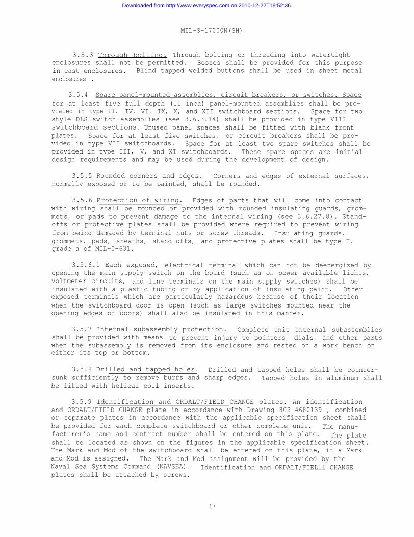
3.5.3 Through bolting. Through bolting or threading into watertightenclosures shall not be permitted. Bosses shall be provided for this purposein cast enclosures. Blind tapped welded buttons shall be used in sheet metalenclosures .
3.5.4 Spare panel-mounted assemblies, circuit breakers, or switches. Spacefor at least five full depth (11 inch) panel-mounted assemblies shall be pro-vialed in type II, IV, VI, IX, X, and XII switchboard sections. Space for twostyle DLS switch assemblies (see 3.6.3.14) shall be provided in type VIIIswitchboard sections. Unused panel spaces shall be fitted with blank frontplates. Space for at least five switches, or circuit breakers shall be pro-vided in type VII switchboards. Space for at least two spare switches shall beprovided in type III, V, and XI switchboards. These spare spaces are initialdesign requirements and may be used during the development of design.
3.5.5 Rounded corners and edges. Corners and edges of external surfaces,normally exposed or to be painted, shall be rounded.
3.5.6 Protection of wiring. Edges of parts that will come into contactwith wiring shall be rounded or provided with rounded insulating guards, grom–mets, or pads to prevent damage to the internal wiring (see 3.6.27.8). Stand-offs or protective plates shall be provided where required to prevent wiringfrom being damaged by terminal nuts or screw threads. Insulating guards,grommets, pads, sheaths, stand-offs, and protective plates shall be type F,grade a of MIL-I-631.
3.5.6.1 Each exposed, electrical terminal which can not be deenergized byopening the main supply switch on the board (such as on power available lights,voltmeter circuits, and line terminals on the main supply switches) shall beinsulated with a plastic tubing or by application of insulating paint. Otherexposed terminals which are particularly hazardous because of their locationwhen the switchboard door is open (such as large switches mounted near theopening edges of doors) shall also be insulated in this manner.
3.5.7 Internal subassembly protection. Complete unit internal subassembliesshall be provided with means to prevent injury to pointers, dials, and other partswhen the subassembly is removed from its enclosure and rested on a work bench oneither its top or bottom.
3.5.8 Drilled and tapped holes. Drilled and tapped holes shall be counter-sunk sufficiently to remove burrs and sharp edges. Tapped holes in aluminum shallbe fitted with helical coil inserts.
3.5.9 Identification and ORDALT/FIELD CHANGE plates. An identificationand ORDALT/FIELD CHANGE plate in accordance with Drawing 803-4680139 , combinedor separate plates in accordance with the applicable specification sheet shallbe provided for each complete switchboard or other complete unit. The manu-facturer’s name and contract number shall be entered on this plate. The plateshall be located as shown on the figures in the applicable specification sheet.The Mark and Mod of the switchboard shall be entered on this plate, if a Markand Mod is assigned. The Mark and Mod assignment will be provided by theNaval Sea Systems Command (NAVSEA). Identification and ORDALT/FIELll CHANGEplates shall be attached by screws.
17
Downloaded from http://www.everyspec.com on 2010-12-22T18:52:36.
MIL-S-17000N(SH)
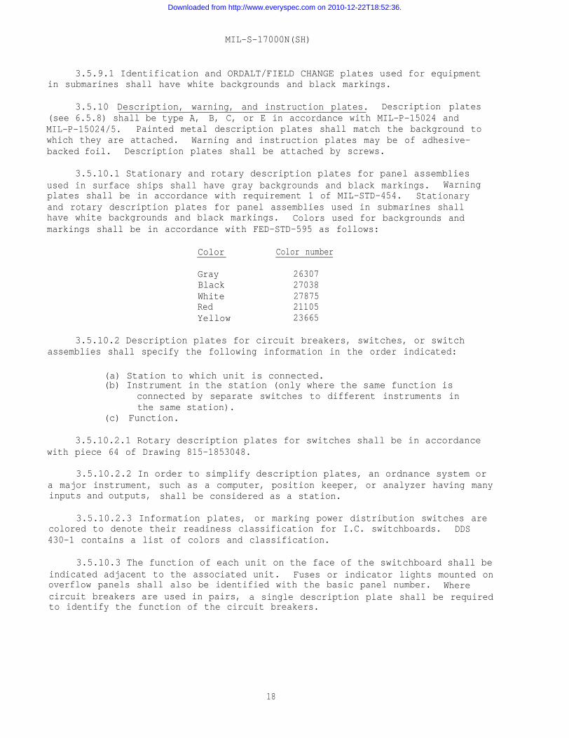
3.5.9.1 Identification and ORDALT/FIELD CHANGE plates used for equipmentin submarines shall have white backgrounds and black markings.
3.5.10 Description, warning, and instruction plates. Description plates(see 6.5.8) shall be type A, B, C, or E in accordance with MIL-P-15024 andMIL-P-15024/5. Painted metal description plates shall match the background towhich they are attached. Warning and instruction plates may be of adhesive-backed foil. Description plates shall be attached by screws.
3.5.10.1 Stationary and rotary description plates for panel assembliesused in surface ships shall have gray backgrounds and black markings. Warningplates shall be in accordance with requirement 1 of MIL-STD-454. Stationaryand rotary description plates for panel assemblies used in submarines shallhave white backgrounds and black markings. Colors used for backgrounds andmarkings shall be in accordance with FED-STD-595 as follows:
Color Color number
Gray 26307Black 27038White 27875Red 21105Yellow 23665
3.5.10.2 Description plates for circuit breakers, switches, or switchassemblies shall specify the following information in the order indicated:
(a) Station to which unit is connected.(b) Instrument in the station (only where the same function is
connected by separate switches to different instruments inthe same station).
(c) Function.
3.5.10.2.1 Rotary description plates for switches shall be in accordancewith piece 64 of Drawing 815-1853048.
3.5.10.2.2 In order to simplify description plates, an ordnance system ora major instrument, such as a computer, position keeper, or analyzer having manyinputs and outputs, shall be considered as a station.
3.5.10.2.3 Information plates, or marking power distribution switches arecolored to denote their readiness classification for I.C. switchboards. DDS430-1 contains a list of colors and classification.
3.5.10.3 The function of each unit on the face of the switchboard shall beindicated adjacent to the associated unit. Fuses or indicator lights mounted onoverflow panels shall also be identified with the basic panel number. Wherecircuit breakers are used in pairs, a single description plate shall be requiredto identify the function of the circuit breakers.
18
Downloaded from http://www.everyspec.com on 2010-12-22T18:52:36.
MIL-S-17000N(SH)
3.5.10.4 Revision record card (see 6.5.8.1). When specified (see 6.2.1),a card approximately 8 by 10 inches in size shall be provided for each switch-board. This card shall contain a list of detail schematic wiring diagrams,back section terminal layout or back section connector location (as applicable)and front panel layout applicable to the switchboard together with the revisionof these drawings in effect at time of delivery. This card shall be suitablefor recording the revision changes as described in the ORDALT or field changeinstructions. It shall be stowed in the card holder (see 3.5.2.13).
3.5.11 Designation of panel assemblies, terminals, and parts.
3.5.11.1 Panel assembly number. Each panel-mounted assembly or switchspace on the switchboard shall be numbered consecutively starting at the left(operator’s left) top corner of the switchboard and numbering downward in eachcolumn and in successive columns to the right. Stationary description plateshall be marked with the applicable number. This number shall also be markedon the back of the door or switchboard frame for all panel spaces.
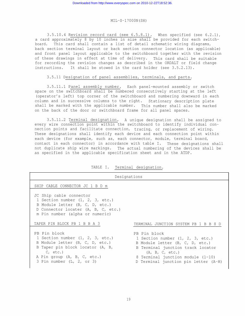
3.5.11.2 Terminal designation. A unique designation shall be assigned toevery wire connection point within the switchboard to identify individual con-nection points and facilitate connection, tracing, or replacement of wiring.These designations shall identify each device and each connection point withineach device (for example, such as, each connector, module, terminal board,contact in each connector) in accordance with table I. These designations shallnot duplicate ship wire markings. The actual numbering of the devices shall beas specified in the applicable specification sheet and in the ATDP.
TABLE I. Terminal designation.
Designations
SHIP CABLE CONNECTOR JC 1 B D m
JC Ship cable connector1 Section number (1, 2, 3, etc.)B Module letter (B, C, D, etc.)D Connector locater (A, B, C, etc.)m Pin number (alpha or numeric)
TAPER PIN BLOCK PB 1 B B A 3
PB Pin block1 Section number (1, 2, 3, etc.)B Module letter (B, C, D, etc.)B Taper pin block locator (A, B,
C, etc.)A Pin group (A, B, C, etc.)3 Pin number (L, 2, or 3)
TERMINAL JUNCTION SYSTEM PB 1 B B 8 D
PB Pin block1 Section number (1, 2, 3, etc.)B Module letter (B, C, D, etc.)B Terminal junction track locator
(A, B, C, etc.)8 Terminal junction module (1-10)D Terminal junction pin letter (A-H)
19
Downloaded from http://www.everyspec.com on 2010-12-22T18:52:36.
MIL-S-17000N(SH)
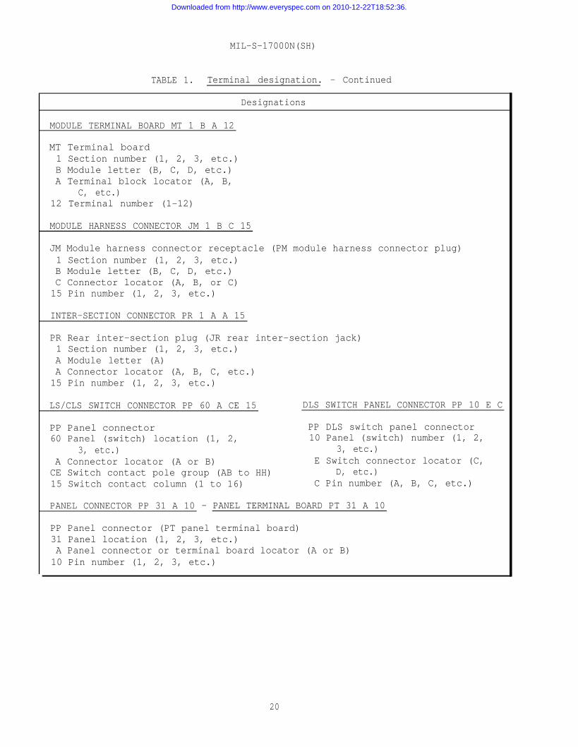
TABLE 1. Terminal designation. - Continued
Designations
MODULE TERMINAL BOARD MT 1 B A 12
MT Terminal board1 Section number (1, 2, 3, etc.)B Module letter (B, C, D, etc.)A Terminal block locator (A, B,
C, etc.)12 Terminal number (1-12)
MODULE HARNESS CONNECTOR JM 1 B C 15
JM Module harness connector receptacle (PM module harness connector plug)1 Section number (1, 2, 3, etc.)B Module letter (B, C, D, etc.)C Connector locator (A, B, or C)15 Pin number (1, 2, 3, etc.)
INTER-SECTION CONNECTOR PR 1 A A 15
PR Rear inter-section plug (JR rear inter-section jack)1 Section number (1, 2, 3, etc.)A Module letter (A)A Connector locator (A, B, C, etc.)15 Pin number (1, 2, 3, etc.)
LS/CLS SWITCH CONNECTOR PP 60 A CE 15 DLS SWITCH PANEL CONNECTOR PP 10 E C
PP Panel connector PP DLS switch panel connector60 Panel (switch) location (1, 2, 10 Panel (switch) number (1, 2,
3, etc.) 3, etc.)A Connector locator (A or B) E Switch connector locator (C,CE Switch contact pole group (AB to HH) D, etc.)15 Switch contact column (1 to 16) C Pin number (A, B, C, etc.)
PANEL CONNECTOR PP 31 A 10 - PANEL TERMINAL BOARD PT 31 A 10
PP Panel connector (PT panel terminal board)31 Panel location (1, 2, 3, etc.)A Panel connector or terminal board locator (A or B)10 Pin number (1, 2, 3, etc.)
20
Downloaded from http://www.everyspec.com on 2010-12-22T18:52:36.
MIL-S-17000N(SH)
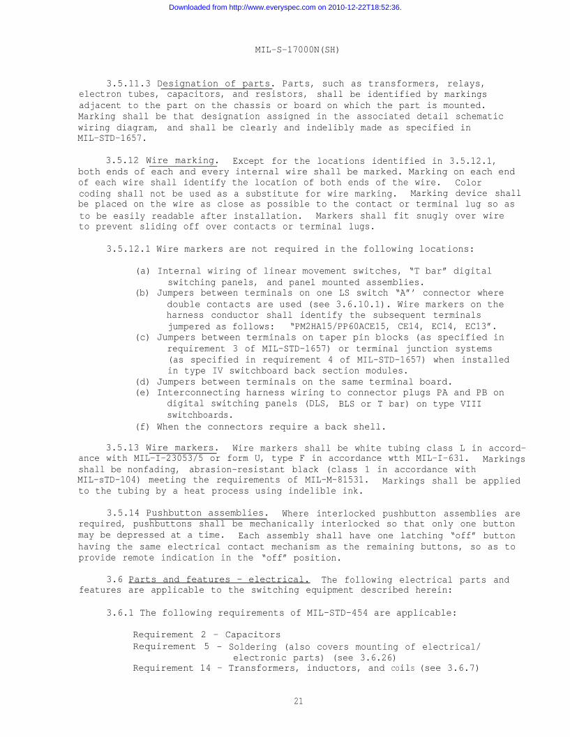
3.5.11.3 Designation of parts. Parts, such as transformers, relays,electron tubes, capacitors, and resistors, shall be identified by markingsadjacent to the part on the chassis or board on which the part is mounted.Marking shall be that designation assigned in the associated detail schematicwiring diagram, and shall be clearly and indelibly made as specified inMIL-STD-1657.
3.5.12 Wire marking. Except for the locations identified in 3.5.12.1,both ends of each and every internal wire shall be marked. Marking on each endof each wire shall identify the location of both ends of the wire. Colorcoding shall not be used as a substitute for wire marking. Marking device shallbe placed on the wire as close as possible to the contact or terminal lug so asto be easily readable after installation. Markers shall fit snugly over wireto prevent sliding off over contacts or terminal lugs.
3.5.12.1 Wire markers are not required in the following locations:
(a) Internal wiring of linear movement switches, “T bar” digitalswitching panels, and panel mounted assemblies.
(b) Jumpers between terminals on one LS switch “A”’ connector wheredouble contacts are used (see 3.6.10.1). Wire markers on theharness conductor shall identify the subsequent terminalsjumpered as follows: “PM2HA15/PP60ACE15, CE14, EC14, EC13”.
(c) Jumpers between terminals on taper pin blocks (as specified inrequirement 3 of MIL-STD-1657) or terminal junction systems(as specified in requirement 4 of MIL-STD-1657) when installedin type IV switchboard back section modules.
(d) Jumpers between terminals on the same terminal board.(e) Interconnecting harness wiring to connector plugs PA and PB on
digital switching panels (DLS, BLS or T bar) on type VIIIswitchboards.
(f) When the connectors require a back shell.
3.5.13 Wire markers. Wire markers shall be white tubing class L in accord-ance with MIL-I-23053/5 or form U, type F in accordance wtth MIL-I-631. Markingsshall be nonfading, abrasion-resistant black (class 1 in accordance withMIL-sTD-104) meeting the requirements of MIL-M-81531. Markings shall be appliedto the tubing by a heat process using indelible ink.
3.5.14 Pushbutton assemblies. Where interlocked pushbutton assemblies arerequired, pushbuttons shall be mechanically interlocked so that only one buttonmay be depressed at a time. Each assembly shall have one latching “off” buttonhaving the same electrical contact mechanism as the remaining buttons, so as toprovide remote indication in the “off” position.
3.6 Parts and features - electrical. The following electrical parts andfeatures are applicable to the switching equipment described herein:
3.6.1 The following requirements of MIL-STD-454 are applicable:
Requirement 2 - CapacitorsRequirement 5 - Soldering (also covers mounting of electrical/
electronic parts) (see 3.6.26)Requirement 14 – Transformers, inductors, and COilS (see 3.6.7)
21
Downloaded from http://www.everyspec.com on 2010-12-22T18:52:36.
MIL-S-17000N(SH)
RequirementRequirementRequirementRequirementRequirementRequirementRequirementRequirement
18 -24 -29 -30 -33 -37 -56 -69 -
Derating of electronic parts and materialsWelds, resistance, electrical interconnectionsElectron tubesSemiconductor devicesResistorsCircuit breakersRotary servo devicesInternal wiring practices
3.6.1.1 Figures 3 and 4 show one-line wiring diagrams of typical I.C.switchboards. The characteristics of each I.C. switchboard, the power suppliesand bus arrangements and the switchboard parts required shall be as specified(see 6.2.1). (See figures 3 and 4.)
3.6.2 Standard electronic and electrical parts. Standard electronic andelectrical parts, defined as tHose listed in MIL-STD-242, shall be used whenthe part is not specified herein. The procedure for the selection of electronicand electrical parts and materials not specified herein or in MIL-STD-242 shallbe in accordance with MIL-STD-965 and the data ordering document included inthe contract (see 6.2.2).
3.6.3 Switches. Type LS switches (see 3.6.3.14) shall be used as theprimary switch in all switchboards except for type VII.
3.6.3.1 Switch assemblies (see 6.5.3). Normally only one switch of therotary selector or snap––type along with associated fuseholders and indicatorlights shall be mounted in a panel assembly (see 6.5.4). However, when speci-fied in the ATDP, two rotary or snap switches may be mounted in one panelassembly. Where sufficient space is not available within the assembly for theassociated items, those i.n excess may be located on a nearby panel on the sameswitchboard section, preferably in the same horizontal row.
3.6.3.1.1 Type JR 10 rotary switches shall be used in place of snap typerotary switches as “power supply (ON/OFF)” switches, for loads not in excessof 10 amperes (A) unless otherwise specified in the ATDP.
3.6.3.1.2 For rotary or snap type switch assemblies, internal switchwiring shall terminate on the fixed part of a connector receptacle with pincontacts (or terminal board for loads in excess of 10 A) which shall be mountedon the rear of the assembly.
3.6.3.1.3 Remotely operated RLS switches include remote control circuitaccessories (toggle switch, indicator lights, and fuseholders) and provide spacefor mounting up to four additional fuseholders to accommodate up to eight loadcircuit fuses. Manually operated MLS and MBLS switches provide space for mountingup to six fuseholders to accommodate up to 12 load circuit fuses. Manuallyoperated MCLS switches may have provisions for any load circuit fuses. Remotelyoperated RDLS switches include remote control circuit accessories (same as forRLS but do not have provision for any load circuit fuses).
3.6.3.1.4 When supplying power, switch contacts shall not be paralleledto obtain increased current carrying capacity. The large load shall be splitbetween two separate sets of switch contacts and associated separate wiring.
22
Downloaded from http://www.everyspec.com on 2010-12-22T18:52:36.
MIL-S-17000N(SH)
3.6.3.2 Switch mounting. Switches shall be mounted so that the switchhandle will be vertical on vertical panels or perpendicular to the operatingedge on sloping or horizontal panels, when the switches are in their normaloperating position. Normal operating position will be specified in the ATDP.Switch styles JR, JM, JK, lSR, and 6SR over nine sections and JL, MO and MCover five sections shall be secured at the rear to protect against damage dueto shock.
3.6.3.3 Blank switch positions. Blank positions shall not be locatedbetween two used positions of rotary or linear movement switches used for systemcircuit switching. Transfer of circuits shall be from one active position ofthe switch to an adjacent active position. Stops shall be provided on rotaryand linear movement switches to prevent moving switch contacts to blank positions.
3.6.3.4 Spare switch poles. Where two or more switches are required toswitch one group of functions to a particular station (such as a launcher assignswitch), at least 10 percent of the total poles shall be provided as spares onone switch of the group. (See 3.6.27.1 regarding information on grouping ofcircuits through a switch.) Where five or more switches are specified in theATDP to switch one group of functions, a spare panel space (see 3.5.4) shallbe provided adjacent to these switches. Switch pole requirements specifiedherein are minimum requirements and are not intended to restrict the use ofmore switches where separation of circuits would help in eliminating electricalinterference between circuits. Spare switch poles specified herein are require-ments applicable to the initial design of the switchboard and may be used upduring development of the design.
3.6.3.5 Switch arrangement. Switch assemblies shall be arranged or groupedtogether for one station (such as a signal data converter or a fire control sys-tem) without regard to whether switches are manually or remotely operated. Whenpracticable, switches for one station shall be in one vertical column andswitches for one function or related functions shall be in one horizontal row.In order to reduce inter-switch harness density, switch assemblies for onestation may be located adjacent to each other or in separate switchboard sectionsof a multi-section switchboard.
3.6.3.6 Thumbwheel switches. Rotary (thumbwheel, in-line) switches shallbe in accordance with MIL-s-2271O.
3.6.3.7 Toggle switches. Toggle switches shall be in accordance withMIL-S-3950.
3.6.3.8 Sensitive switches. Sensitive switches shall be in accordancewith MIL-S-8805.
3.6.3.9 Manual operated rotary selector switches. Rotary selector switchesshall be in accordance with MIL-S-21604, or as specified in the ATDP. StyleJR and JM switches shall be 25 sections, except that 15 sections or less maybe used where these switches are specified in a switchboard using style LS,BLS, CLS, or JLS switches (see 3.6.3.1.1 for exception).
3.6.3.9.1 Type S-JF shall not be used in I.C. switchboards.
23
Downloaded from http://www.everyspec.com on 2010-12-22T18:52:36.
MIL-S-17000N(SH)
3.6.3.10 Remote operated rotary selector switches. Remote operatedrotary selector switches in accordance with MIL-R-16999 shall not be used inswitchboards.
3.6.3.10.1 Unless specified in the ATDP, modified bus transfer switchesin accordance with MIL-S-17773 shall be used for direct current (d.c.) circuitsor for higher voltages and currents than the rating of the type S-JR switch.
3.6.3.11 Power type rotary switches. Power type rotary switches (snapswitches) shall be in accordance with MIL-S-15291 (see 3.6.3.1.1 for exception).Remote operated power type rotary switches shall be in accordance with the ATDP.
3.6.3.11.1 Master switches. Master switches for power conversion equipmentconnected to the switchboard shall be 3 wire pushbutton type in accordance withMIL-C-2212 and as specified (see 6.2.1.)
3.6.3.11.2 Switching units, power transfer. Switching units, power transfershall be in accordance with MIL-S-17773.
3.6.3.12 Pushbutton switches. Illuminated pushbutton switches shall bein accordance with MIL-S-22885, as specified in the ATDP. Panel seals, ifrequired for watertight applications, shall be in accordance with MIL-S-22885.Nonilluminated push button switches shall be in accordance with MIL-S-8805.Boots, if required for watertight applications, shall be in accordance withMIL-B-5423.
3.6.3.13 Meter switches. Separate switches shall be provided for bothalternating current (a.c.) and d.c. voltmeters. Power distribution switchboards(type VII) meter switching shall be in accordance with MIL-S-18396 or asspecified in the ATDP.
3.6.3.13.1 Voltmeter select switches shall be type 1SR2E2 in accordancewith MIL-S-15291, or as specified in the ATDP. Voltmeter select switchesshall provide ground detector readings on each side of a.c. and d.c. buses.
3.6.3.13.2 Bus select switches shall be type S3JK3 in accordance withMIL-S-21604/2. Where more than 15 buses are required to be monitored, two busselect switches shall be installed. Bus select switches shall provide voltagereadings on each phase of each a.c. bus and each d.c. bus.
3.6.3.13.3 Resistors and shunts for metering shall be in accordance withMIL-I-1361 and shall be high-impact (H.I.) shock resistant. Variable resistorsfor voltage and frequency control of motor generators or static power supplieswhen they are to be controlled from the I.C. switchboard shall be as specified.
3.6.3.14 Linear movement switches. Linear movement switches shall be inaccordance with the following:
24
Downloaded from http://www.everyspec.com on 2010-12-22T18:52:36.
MIL-S-17000N(SH)
Switch style Specification sheet Drawing number
LSBLSCLSDLS
Enclosed LSJLSSLS
KLS
MIL-S-24187/lMIL-S-24187/2MIL-S-24187/3MIL-S-24187/4MIL-S-24187/lMIL-S-24187/5MIL-S-24187/6
MIL-S-24187/7
815-1853048803-1853221803-4680150803-4680149815-1853049803-4680151(Inactive fornew design)
803-5002990
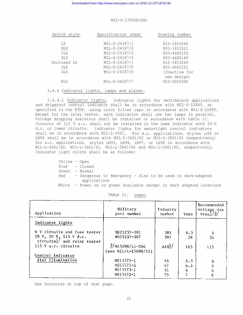
3.6.4 Indicator lights, lamps and alarms.
3.6.4.1 Indicator lights. Indicator lights for switchboard applicationsand dripproof control indicator shall be in accordance with MIL-S-22885, asspecified in the ATDP, using color filter caps in accordance with MIL-S-22885.Except for the relay tester, each indication shall use two lamps in parallel.Voltage dropping resistors shall be installed in accordance with table II.Circuits of 115 V a.c. shall not be installed in the same indicator with 50-Vd.c. or lower circuits. Indicator lights for watertight control indicatorsshall be in accordance with MIL-L-3661. For d.c. applications, styles LH95 orLH96 shall be in accordance with MIL-L-3661/62 or MIL-L-3661/63 respectively;for a.c. applications, styles LH93, LH94, LH97, or LH98 in accordance withMIL-L-3661/60, MIL-L-3661/61, MIL-L-3661/64 and MIL-L-3661/65, respectively.Indicator light colors shall be as follows:
Yellow - OpenBlue - ClosedGreen - NormalRed - Dangerous or Emergency - Also to be used in dark-adapted
applicationsWhite - Power on or power available except in dark adapted locations
TABLE II. Lamps.
See footnotes at top of next page.
25
Downloaded from http://www.everyspec.com on 2010-12-22T18:52:36.
MIL-S-17000N(SH)
1 / On 50-V circuits, use one 2-watt 620-ohm voltage dropping resistor for eachlamp. On 28-V circuits, use one l-watt 100-ohm voltage dropping resistorfor each lamp. On 115 V d.c. circuits use one 7-watt 2260-ohm voltagedropping resistor for each lamp.
2 / AIH lamps require the use of an external l/4-watt 47K ohm current limitingresistor.
2 / Conforming to MIL-L-15098 and MIL-L-15098/11.
3.6.4.1.1 Indicator light and push button switch combinations shall be inaccordance with MIL-S-22885, as specified in the ATDP.
3.6.4.1.2 Power available lights. Unless otherwise specified in the ATDP,power available indicator lights in accordance with MIL-S-22885 shall be providedfor supply circuits entering a switchboard, other control switchboards, andcontrol system components. For 3-phase power supplies, power available lightsshall be provided for all three phases. Power available lights need not beprovided on I.C. switchboards for supplies which are connected via ABT switcheshaving power available lights that are visible to the switchboard operator.
3.6.4.1.2.1 The cutouts for indicator lights or indicator light and pushbutton switches shall conform to the applicable specification sheet ofMIL-S-22885.
3.6.4.2 Lamps. Lamps shall be in accordance with MIL-L-6363, MIL-L-15098and MIL-L-15098/11 for the applications as specified in table II. Lamps used forcontrol indicator dial illumination shall be energized from the secondary ofa transformer, and the lighting circuit shall be equipped with a control deviceto vary light intensity from maximum value to full extinction when all lamps,or 50 percent of the lamps are operative. At 115 V input to the illuminationtransformer, and with all lamps operative, the lamp socket voltages shall notexceed the values as shown in table II. Rheostats shall not be used.
3.6.4.3 Bus failure alarms. Provision shall be made on main I.C. switch-boards for connection of a bus failure alarm to each 28 V, 50 V, 120 V and 450 Vbus (see figure 3) unless it is supplied from a local source for which audiblepower failure indication already exists (see 6.2.1).
3.6.4.3.1 Bus failure alarms shall be in accordance with Drawing804-1853042, type IC/EIDl in accordance with MIL-A-15303, except for constantfrequency buses which shall be as specified in 3.6.4.3.2. When used to monitor28 V, d.c. or 50 V, d.c. buses, type IC/EIDl alarms shall be connected to 120 V,60 hertz (Hz) power, and controlled by a relay connected to the bus. When usedto monitor 450 V, 60 or 400 Hz buses, type IC/EIDl alarms shall be connectedto the bus through a transformer to provide the necessary operating voltage tothe alarm unit. Associated batteries, relays, and transformers shall befurnished by the installin~ activity.
3.6.4.3.2 The alarm circuit for the constant frequency bus shall providefor indication of maloperation or failure of the constant frequency controlunit. The circuit arrangement shown on figure 3 shall be followed. An audiblesignal (type IC/BlS4, or H2S4) in accordance with MIL-A-15303, and all necesaryrelays, will be furnished by the switchboard installing activity.
26
Downloaded from http://www.everyspec.com on 2010-12-22T18:52:36.
MIL-S-17000N( SH)
3.6.5 Fuses, fuseholders, fusing, and circuit breakers.
3.6.5.1 Fuses. Fuses shall be style F03 or F77A in accordance withMIL-F-15160/3 or MIL-F-15160/77 and shall be provided and installed as requiredby the applicable detail schematic wiring diagrams. Fuses under 1 A ratingshall not be used. Fuse size shall be indicated by marking adjacent to eachfuse. Unless required by the detail schematic wiring diagrams to be on thesupply side of the switch, fuses shall be on the load side of the switch.
3.6.5.1.1 Spare fuse stowage. One “short depth” panel space for sparefuse stowage shall be provided for each three switchboard sections or fractionthereof. Each panel space shall contain four sectioned drawers of sufficientsize to stow the spare fuses provided for the associated sections (see 3.9 forapproximate quantities). Drawers shall be provided with a door to preventtheir being dislodged under shock. Door shall be secured with a flush cabinetlatch.
3.6.5.2 Fuseholders. Fuseholders shall be located on the operating surfaceof equipments, except where location within equipment is specified in the ATDP.Inside locations of fuseholders will be specified only where utmost space economyis necessary and the fused circuit is nonvital. Where a color cap is used toindicate a specific voltage rating of a fuseholder, a paint or decal marker (thesame color as the cap of the fuse carrier) shall be located adjacent to the fuse-holder.
3.6.5.2.1 Fuseholders shall be of the dead-front blown-fuse indicatingtypes as specified in 3.6.5.2.1.1 and 3.6.5.2.1.2.
3.6.5.2.1.1 For circuit loads from 1 to 15 A and voltages up to 125 V a.c.and d.c. type FHL57G fuseholders conforming to MIL-F-19207 and MIL-F-19207/38shall be used, using fuse style F77A in accordance with MIL-F-15160/77.
3.6.5.2.1.2 For circuit loads of 16 to 30 A, type FHL29G fuseholdersconforming to MIL-F-19207 and MIL-F-19207/18 shall be used on 12- to 90-Vcircuits and type FHL1OU fuseholders conforming to MIL-F-19207 and MIL-F-19207/lshall be used on 91- to 250-V circuits, using fuse style F03 in accordancewith MIL-F-15160/3.
3.6.5.2.1.3 Meter circuits, buses, bus transfers, alarms, and feeders toand from I.C. power converting equipment shall be in accordance with applicableportions of figure 3. Fuses of 65 A or higher ratings which are used in trans-formers bank primary circuits in accordance with figure 3 may be mounted inshock and vibration proof open clips within the switchboard enclosure (450 Vunit) provided that associated blown fuse indicators are mounted on the hingedpanel and are plainly visible from the front of the switchboard with doorsclosed. Secondary coils of current transformers shall be connected in such amanner that whenever the coil, if not supplying current for a particular use,will be shorted by the connecting transfer switch.
3.6.5.3 Blown fuse indicator circuit. Blown fuse indicator circuit usedwith the type FHL57G fuseholders conforming to MIL-F-19207 and MIL-F-19207/38shall be energized from the 115-V 60-Hz miscellaneous supply circuit throughfuses located on the power available indicator light panel. Specific circuitswill be shown on the applicable detail schematic wiring diagrams.
27
Downloaded from http://www.everyspec.com on 2010-12-22T18:52:36.
MIL-S-17000N(SH)
3.6.5.4 Circuit breakers. Circuit breakers, type ALB in accordance withMIL-C-17588, or type AQB in accordance with MIL-C-17361 as applicable, may beused in motor supply circuits having inrush currents. Unless specified in theATDP, circuit breakers shall not be used in other circuits.
3.6.6 Connectors. Connectors shall be of the type that use crimp typeremovable contacts in accordance with 3.6.6.1 through 3.6.6.3. A minimum ofone of each type of mating connector shall be provided as spares in the INCOkits as pertains to each respective switchboard.
3.6.6.1 Harness wiring connectors. Unless otherwise specified in theATDP, connectors used on internal harness wiring (on back section modules andon panel-mounted assemblies) shall be in accordance with MIL-C-28748. Partnumber M28748/09FONOlA in accordance with MIL-C-28748/9 shall be used on fixedstructures and part number M28748/10FOALIA in accordance with MIL-C-28748/10shall be used on harness and intersection wiring.
3.6.6.2 Linear movement switch connectors. Connectors used on linearmovement switches shall be in accordance with MIL-C-28731 or as specified onthe applicable drawings listed in 3.6.3.14.
3.6.6.3 Ship cable connectors. For types IV, V, VI, IX, and XII switch-boards and when specified (see 6.2.1) for control indicators, connectors usedwith ship cables shall be class D in accordance with MIL-C-5015 or equivalentor MIL-C-39012 (for coaxial cables) as specified in the ATDP. Box mountedconnector receptacles in accordance with MS3402 (with pin contacts) shall beinstalled on the switchboards and the control indicator. When the connectorreceptacle is mounted in a vertical or angled position, the keyway shall be atthe top. When the connector receptacle is mounted in a horizontal position, thekeyway shall be towards the front of the switchboard. Mating connector plugsto be installed on ship cables shall be in accordance with MS3406 (with socketcontacts). For type IV switchboards, the back shells shall be 45-degree strainrelief clamps in accordance with MS3415. For type V switchboards, the backshells shall be straight strain relief clamps in accordance with MS3417. Fortypes VI and IX switchboards, the backshells shall be specified in the ATDP.Connector plugs used with type 2U45 cable conforming to MIL-C-915/63 shall useinsert arrangement 44-52 with size 16-22 socket contacts. For type VIII switch-boards, connectors used with ship cables shall be in accordance with MIL-C-28731.The specific part numbers of the connector receptacles on the switchboard andof the connector plugs on the ship cables shall be specified in the ATDP.Mating ship cable connector plugs shall be furnished and shipped with eachswitchboard if not furnished as part of the wiring fixture (see 3.8 and 5.1.3).Connector contacts for size 8 AWG wire or larger may be solder type.
3.6.6.3.1 MS sheets specified herein shall be adhered to and all connectorsshall be of the front release type. Tool and ancillary items shall be compatiblewith the specific connectors provided.
3.6.7 Transformers and inductors. Transformers and inductors shall be in— .accordance with requirement 14 of MIL-STD-454 and transformers shall be grade 5,class S of MIL-T-27.
28
Downloaded from http://www.everyspec.com on 2010-12-22T18:52:36.
MIL-S-17000N(SH)
3.6.7.1 Current transformers. Current transformers for metering andrelaying shall be in accordance with MIL-I-1361, shall have a Navy classifica-tion accuracy NSS, and shall be H.I. resistant. Transformer protective devicesshall be in accordance with MIL-I-1361.
3.6.7.2 Potential transformers. Potential transformers for meteringshall be in accordance with MIL-I-1361, shall have a Navy classificationaccuracy NSS, shall be H.I. shock resistant, and shall have a standard burdenrating of not less than 100 V A.
3.6.8 Relays. Relays shall be provided and installed (see 3.6.14) asspecified in the ATDP and shall conform to the following:
(a) D.C. relays shall have arc suppression circuitry for the coilprovided as an integral part of the relay.
(b) 4PDT relays shall be 28 V d.c., 48 V d.c. 115 V 60 Hz, or115 V 400 Hz in accordance with MIL-R-6106 and MS27400.
(c) 24PDT and 48PDT relays shall be in accordance with MIL-R-5757and Drawing 803-4680146.
(d) 4PDT latching relays shall be in accordance with MIL-R-6106and MS27745.
(e) lPST and 3PST relays used in type VII switchboards shall be inaccordance with MIL-R-6106 and MS24140, MS24168, or MS27997.
3.6.9 Synchros. Internal unit connections and wire markings shall be inaccordance with requirement 2 of MIL-STD-1657.
3.6.9.1 Synchro capacitors. Synchro capacitors as specified in the ATDPshall be connected across the stator leads of differential transmitters andcontrol transformers. Synchro capacitors shall be delta connected, and ratedat 600 V d.c. for 60 Hz synchros and 1,000 V d.c. for 400 Hz synchros. Thethree capacitors used as a bank for one synchro shall be matched within 1percent. Each capacitor shall have the values shown in MIL-HDBK-225 withinplus or minus 10 percent.
3.6.9.2 Synchro electrical zero and equipment mechanical zero. It isessential that synchro components be correctly alined with respect to each other,and to the device or parent equipment with which they are used. Electricalzero is the reference point for alinement of all synchro components. Mechanicalzero or reference point for the device or parent equipment using synchro compo-nents depends upon the particular application of the equipment involved.Whenever a synchro component is used, either as a transmitter or receiver, thesynchro electrical zero and the equipment mechanical zero, unless otherwisespecified in the ATDP, shall be physically positioned to the same point. Synchrosshall be electrically zeroed by the methods specified in MIL-HDBK-225 prior todelivery of equipment.
3.6.10 Wire terminal lugs. Except for contacts used with connectors,pressure grip terminal lugs in accordance with figure titled “Type WTG terminals,square tongue, one bolt hole” of MIL-T-16366 or MIL-T-7928 shall be used. In-sulated barrel terminal lugs shall be used. Terminal lugs with projections or“lips” shall be used in cases where necessary to prevent turning of terminallugs and shorting due to close clearances. Terminal lugs for connection of shipwiring are not required to be provided by the manufacturer.
29
Downloaded from http://www.everyspec.com on 2010-12-22T18:52:36.
MIL-S-17000N(SH)
3.6.10.1 Only one wire shall be crimped to a terminal lug or a singleconnector contact except where specified in the ATDP for DLS switches and wherea double wire crimp contact in accordance with MIL-C-28731/23 is used on classLS switches. When the double contact is used an insulated sleeve (class 1,black, in accordance with MIL-I-23053 and MIL-I-23053/5) shall be installedover the double contact after the wires are crimped. In-line splices shallnot be used as a substitute for the double wire contact. Frequency used combina-tions of wires that may be crimped in the double contact are as follows:
(a) Two 16-AWG wires(b) Two 18-AWG wires(c) Two 20-AWG wires(d) One 20-AWG wire and one 16-AWG wire
3.6.11 Terminal boards. Terminal boards shall be of the stud type inaccordance with MIL-T-55164 as specified in the ATDP and as specified in 3.6.11.1through 3.6.11.4.
3.6.11.1 The maximum number of wires to be connected to any one terminalshall be as specified in the applicable specification sheet of MIL-T-55164. Inwiring these terminal boards with the terminal lugs specified in the applicablespecification sheet of MIL-T-55164, lock washers are not required. The studs ofterminal boards, except those designated to receive ship wiring, shall be fittedwith a full complement of barrel nuts. Barrel nuts for securing the terminallugs of ship wiring shall not be assembled on the equipment but shall be fur-nished in sturdy textile bags (one size per bag) and packed as required in 5.1.3.Solder type terminals boards shall not be used.
3.6.11.2 Terminal board mounting. Terminal boards for receiving shipcables on other than types VI and IX switchboards shall be secured to a fixedportion of the enclosure, not to hinged panels or other movable assemblies thatmay require flexing of the ship wiring during normal operation or servicing.Terminal boards shall be mounted so that they will not be broken or stressedby distortion of the enclosure. Terminal boards shall be secured only bymachine screws threaded into the supporting member (an insert is required inaccordance with requirement 12 of MIL-STD-454 if the tapped material is aluminumalloy) and shall be capable of ready removal of replacement. Access to thebackside of the supporting member shall not be required for removal of terminalboards.
3.6.11.3 Spare module terminals. At least 20 percent of the terminals oneach module shall be spares. Spare terminals shall not be wired to the moduleconnectors. These spare terminals are initial design requirements and may beused during development of the design.
3.6.11.4 Terminating large conductor ship cables. Provision shall be madefor terminating large conductor ship cables for power supplies to switchboardbusses or those that may be increased in size for voltage drop considerationsby the use of jumper straps or terminal boards with larger current ratings asspecified in requirement 1 of MIL-STD-1657. The large terminal boards shall belocated on modules located in the lower positions of the back section. In someinstances, internal switchboard branch circuits may require the use of morethan one terminal on a terminal board. Jumper straps shall be provided to
30
Downloaded from http://www.everyspec.com on 2010-12-22T18:52:36.
MIL-S-17000N(SH)
either connect one large ship conductor or two or more terminals or connecttwo or more terminals together for internal switchboard branching. Specialcare shall be taken to maintain the clearances specified in 3.6.29 for thesestraps between adjacent terminal boards.
3.6.12 Taper pin blocks. Taper pin blocks as used in switchboards shallbe in accordance with requirement 3 of MIL-STD-1657.
3.6.13 Terminal junction systems. Terminal junction systems as used inswitchboards shall be in accordance with requirement 4 of MIL-STD-1657.
3.6.14 Sockets. Tube, relay, or capacitor sockets shall be of the singleunit type in accordance with MIL-S-12883 and as specified in 3.6.14.1 through3.6.14.4. Gang type sockets are not acceptable. (This requirement is notintended to preclude the assembly of several sockets on a supporting frameproviding the contact clips for any socket are on insulating material which isnot continuous with that of any other socket.) Contact springs shall havepositive contact and positive action.
3.6.14.1 Relay sockets for a.c. 4PDT relays shall be DAN-L, Inc. partnumber 62OO-104SXH, or equal.
3.6.14.2 Relay sockets for d.c. 4PDT relays shall be DAN-L, Inc. partnumber 62OO-104SH, or equal.
3.6.14.3 Relay sockets for 4PDT latching relays shall be DAN-L, Inc. partnumber 32823-17SH, or equal.
3.6.14.4 Relay sockets for the relay tester shall be in accordance withrequirement 13 of MIL-STD-1657.
3.6.15 Interior section illumination. Interior illumination shall beprovided on all switchboards except types III, V, VI, and VIII by the instal-lation of a fluorescent 8-watt desk light in accordance with MIL-F-16377 andMIL-F-16377/4, and a ballast box in accordance with MIL-F-16377 and MIL-F-16377/46.Power for this light shall be obtained from the ships emergency lighting system.Wiring from the light shall be run to a terminal box (in accordance withMIL-T-24558 and MIL-T-24558/18 symbol 400.1) mounted inside the frame of eachsection. This wiring shall be kept completely separated from other switchboardwiring.
3.6.16 Flasher Panel.
3.6.16.1 Solid state flasher panel. When a solid state flasher panel isspecified in the ATDP, it shall be in accordance with Drawing 803-5476797.
3.6.16.1.1 Spare module cards (as required) shall be included in the SolidState Flasher Panel: Piece numbers 45, 46 and or 47 on Drawing 803-5476797.
3.6.16.2 Mechanical flasher panel. Where a mechanical flasher panel isspecified in the ATDP, it shall be in accordance with requirement 14 ofMIL-STD-1657.
31
Downloaded from http://www.everyspec.com on 2010-12-22T18:52:36.
MIL-S-17000N(SH)
3.6.17 Synchro signal converter. Where a synchro signal converter isspecified in the ATDP, it shall be in accordance with requirement 16 ofMIL-STD-1657, and conform to the requirements of MIL-C-24105.
3.6.18 Test equipment.
3.6.18.1 Meters. Voltmeters and voltmeter switch panels on switchboardsshall be in accordance with requirement 10 of MIL-STD-1657.
3.6.18.1.1 Frequency meters shall be MR49W60BH or MR49W400DH in accord-ance with MIL-M-16125, except frequency meters for measuring type 111 powerfrequency as described in DOD-STD-1399, section 300. Frequency meters formeasuring type 111 power frequency shall be type MR49W41AFH or MR49W42AFH inaccordance with MIL-M-23167.
3.6.18.2 Fuse tester. When specified in the ATDP, a fuse tester inaccordance with requirement 12 of MIL-STD-1657 shall be installed in eachswitchboard.
3.6.18.3 Relay tester. When specified in the ATDP, a relay testerincorporating facilities to test each type of DPDT or 4PDT plug-in relay usedin a switchboard shall be installed. Features and arrangement shall be inaccordance with requirement 13 of MIL-STD-1657.
3.6.18.4 Bus selector switches. Bus selector switch panels on switchboardshall be in accordance with requirement 9 of MIL-STD-1657.
3.6.19 Telephone jack box. One telephone jack in accordance with Drawing9000-S6501-74120, when specified in the ATDP, shall be provided. It shall belocated on the lower panel (kick plate) of the center section of an odd numberedmultiple section switchboard and on the section to the right of center on alleven numbered multiple section switchboards (when viewed from the front of theswitchboard).
3.6.20 Wire.
3.6.20.1 Wire type. Wire type shall be in accordance with the requirementsspecified in 3.6.20.1.1 through 3.6.20.1.4. Wire, except coaxial cables, shallbe of at least 19 strand.
3.6.20.1.1 Wire shall be in accordance with MIL-W-16878 and MIL-W-16878/17(with outer jacket), or MIL-W-16878/18 (with or without outer jacket), or withMIL-W-16878/19, or as specified herein.
3.6.20.1.2 Single conductor shielded wire for radio frequency applicationsshall be coaxial cable in accordance with MIL-C-17.
3.6.20.1.3 Two- and three-conductor unshielded twisted cables shall besimilar to types 2S.J and 3SJ in accordance with MIL-C-915/60 without theshielding braid, fillers, and outer jacket.
32
Downloaded from http://www.everyspec.com on 2010-12-22T18:52:36.
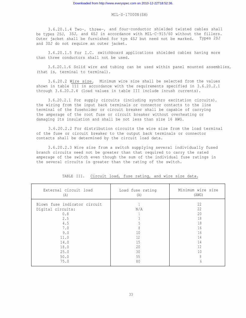
MIL-S-17000N(SH)
3.6.20.1.4 Two-, three-, and four-conductor shielded twisted cables shallbe types 2SJ, 3SJ, and 4SJ in accordance with MIL-C-915/60 without the fillers.Outer jacket shall be furnished for tye 4SJ but need not be marked. Types 2SJand 3SJ do not require an outer jacket.
3.6.20.1.5 For I.C. switchboard applications shielded cables having morethan three conductors shall not be used.
3.6.20.1.6 Solid wire and tubing can be used within panel mounted assemblies,(that is, terminal to terminal).
3.6.20.2 Wire size. Minimum wire size shall be selected from the valuesshown in table 111 in accordance with the requirements specified in 3.6.20.2.1through 3.6.20.2.4 (load values in table III include inrush currents).
3.6.20.2.1 For supply circuits (including synchro excitation circuits),the wiring from the input back terminals or connector contacts to the lineterminal of the fuseholder or circuit breaker shall be capable of carryingthe amperage of the root fuse or circuit breaker without overheating ordamaging its insulation and shall be not less than size 16 AWG.
3.6.20.2.2 For distribution circuits the wire size from the load terminalof the fuse or circuit breaker to the output back terminals or connectorcontacts shall be determined by the circuit load data.
3.6.20.2.3 Wire size from a switch supplying several individually fusedbranch circuits need not be greater than that required to carry the ratedamperage of the switch even though the sum of the individual fuse ratings inthe several circuits is greater than the rating of the switch.
TABLE III. Circuit load, fuse rating, and wire size data.
External circuit load(A)
Blown fuse indicator circuitDigital circuits:
0.82.54.57.09.0
11.014.018.025.050.075.0
Load fuse rating(A)
1N/A1358
10121520305580
Minimum wire size(AWG)
222220181816161414121086
33
Downloaded from http://www.everyspec.com on 2010-12-22T18:52:36.
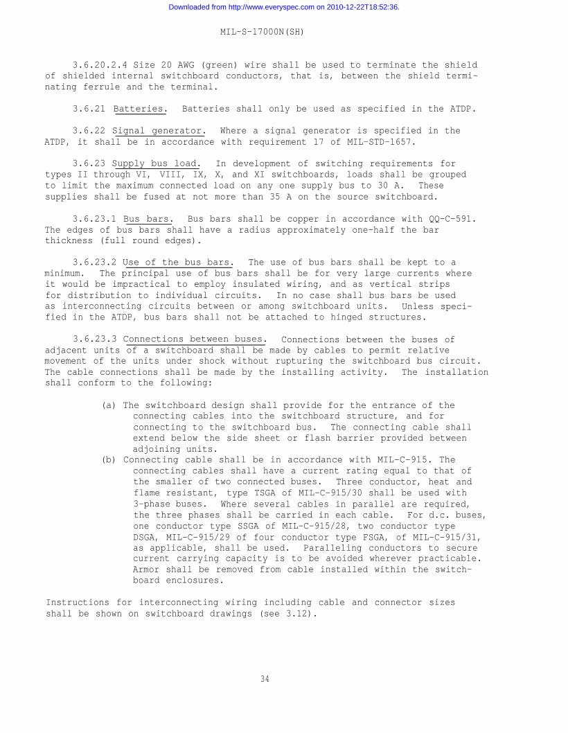
MIL-S-17000N(SH)
3.6.20.2.4 Size 20 AWG (green) wire shall be used to terminate the shieldof shielded internal switchboard conductors, that is, between the shield termi-nating ferrule and the terminal.
3.6.21 Batteries. Batteries shall only be used as specified in the ATDP.
3.6.22 Signal generator. Where a signal generator is specified in theATDP, it shall be in accordance with requirement 17 of MIL-STD-1657.
3.6.23 Supply bus load. In development of switching requirements fortypes II through VI, VIII, IX, X, and XI switchboards, loads shall be groupedto limit the maximum connected load on any one supply bus to 30 A. Thesesupplies shall be fused at not more than 35 A on the source switchboard.
3.6.23.1 Bus bars. Bus bars shall be copper in accordance with QQ-C-591.The edges of bus bars shall have a radius approximately one-half the barthickness (full round edges).
3.6.23.2 Use of the bus bars. The use of bus bars shall be kept to aminimum. The principal use of bus bars shall be for very large currents whereit would be impractical to employ insulated wiring, and as vertical stripsfor distribution to individual circuits. In no case shall bus bars be usedas interconnecting circuits between or among switchboard units. Unless speci-fied in the ATDP, bus bars shall not be attached to hinged structures.
3.6.23.3 Connections between buses. Connections between the buses ofadjacent units of a switchboard shall be made by cables to permit relativemovement of the units under shock without rupturing the switchboard bus circuit.The cable connections shall be made by the installing activity. The installationshall conform to the following:
(a) The switchboard design shall provide for the entrance of theconnecting cables into the switchboard structure, and forconnecting to the switchboard bus. The connecting cable shallextend below the side sheet or flash barrier provided betweenadjoining units.
(b) Connecting cable shall be in accordance with MIL-C-915. Theconnecting cables shall have a current rating equal to that ofthe smaller of two connected buses. Three conductor, heat andflame resistant, type TSGA of MIL-C-915/30 shall be used with3-phase buses. Where several cables in parallel are required,the three phases shall be carried in each cable. For d.c. buses,one conductor type SSGA of MIL-C-915/28, two conductor typeDSGA, MIL-C-915/29 of four conductor type FSGA, of MIL-C-915/31,as applicable, shall be used. Paralleling conductors to securecurrent carrying capacity is to be avoided wherever practicable.Armor shall be removed from cable installed within the switch–board enclosures.
Instructions for interconnecting wiring including cable and connector sizesshall be shown on switchboard drawings (see 3.12).
34
Downloaded from http://www.everyspec.com on 2010-12-22T18:52:36.
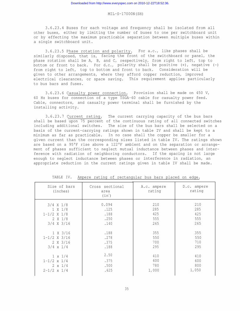
MIL-S-17000N(SH)
3.6.23.4 Buses for each voltage and frequency shall be isolated from allother buses, either by limiting the number of buses to one per switchboard unitor by effecting the maximum practicable separation between multiple buses withina single switchboard unit.
3.6.23.5 Phase rotation and polarity. For a.c., like phases shall besimilarly disposed, that is, facing the front of the switchboard or panel, thephase rotation shall be A, B, and C, respectively, from right to left, top tobottom or front to back. For d.c., polarity shall be positive (+), negative (-)from right to left, top to bottom and front to back. Consideration will begiven to other arrangements, where they afford copper reduction, improved—electrical clearances, or space saving. This requirement applies particularlyto bus bars and fuses.
3.6.23.6 Casualty power connection. Provision shall be made on 450 V,60 Hz buses for connection of a type TSGA-60 cable for casualty power feed.Cable, connectors, and casualty power terminal shall be furnished by theinstalling activity.
3.6.23.7 Current rating. The current carrying capacity of the bus barsshall be based upon 75 percent of the continuous rating of all connected switchesincluding additional switches. The size of the bus bars shall be selected on abasis of the current-carrying ratings shown in table IV and shall be kept to aminimum as far as practicable. In no case shall the copper be smaller for agiven current than the corresponding sizes listed in table IV. The ratings shownare based on a 95°F rise above a 122°F ambient and on the separation or arrange-ment of phases sufficient to neglect mutual inductance between phases and inter-ference with radiation of neighboring conductors. If the spacing is not largeenough to neglect inductance between phases or interference in radiation, anappropriate reduction in the current ratings given in table IV shall be made.
TABLE IV. Ampere rating of rectangular bus bars placed on edge.
Size of bars(inches)
3/4 X 1/81 X 1/8
1-1/2 X 1/82 X 1/8
3/4 X 3/16
1 X 3/161-1/2 X 3/16
2 X 3/163/4 x l/4
1 x 1/41-1/2 x 1/4
2 x 1/42-1/2 x 1/4
Cross sectionalarea(in2)
0.094.125.188.250.140
.188
.278
.375
.188
2.50
.375
.500
.625
A.c. ampererating
210285425555265
355550700295
410600780
1,000
D.c. ampererating
210285425555265
355550710295
410600800
1,050
35
Downloaded from http://www.everyspec.com on 2010-12-22T18:52:36.
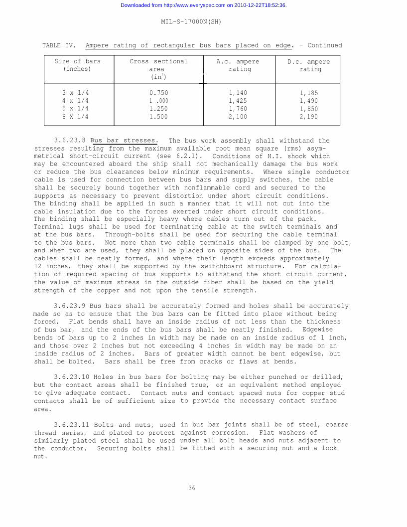
MIL-S-17000N(SH)
TABLE IV. Ampere rating of rectangular bus bars placed on edge. - Continued
Size of bars(inches)
3 x 1/44 x 1/45 x 1/46 X 1/4
Cross sectional A.c. amperearea rating(inZ)
0.750 1,1401 .000 1,4251.250 1,7601.500 2,100
D.c. ampererating
1,1851,4901,8502,190
3.6.23.8 Bus bar stresses. The bus work assembly shall withstand thestresses resulting from the maximum available root mean square (rms) asym-metrical short-circuit current (see 6.2.1). Conditions of H.I. shock whichmay be encountered aboard the ship shall not mechanically damage the bus workor reduce the bus clearances below minimum requirements. Where single conductorcable is used for connection between bus bars and supply switches, the cableshall be securely bound together with nonflammable cord and secured to thesupports as necessary to prevent distortion under short circuit conditions.The binding shall be applied in such a manner that it will not cut into thecable insulation due to the forces exerted under short circuit conditions.The binding shall be especially heavy where cables turn out of the pack.Terminal lugs shall be used for terminating cable at the switch terminals andat the bus bars. Through-bolts shall be used for securing the cable terminalto the bus bars. Not more than two cable terminals shall be clamped by one bolt,and when two are used, they shall be placed on opposite sides of the bus. Thecables shall be neatly formed, and where their length exceeds approximately12 inches, they shall be supported by the switchboard structure. For calcula-tion of required spacing of bus supports to withstand the short circuit current,the value of maximum stress in the outside fiber shall be based on the yieldstrength of the copper and not upon the tensile strength.
3.6.23.9 Bus bars shall be accurately formed and holes shall be accuratelymade so as to ensure that the bus bars can be fitted into place without beingforced. Flat bends shall have an inside radius of not less than the thicknessof bus bar, and the ends of the bus bars shall be neatly finished. Edgewisebends of bars up to 2 inches in width may be made on an inside radius of 1 inch,and those over 2 inches but not exceeding 4 inches in width may be made on aninside radius of 2 inches. Bars of greater width cannot be bent edgewise, butshall be bolted. Bars shall be free from cracks or flaws at bends.
3.6.23.10 Holes in bus bars for bolting may be either punched or drilled,but the contact areas shall be finished true, or an equivalent method employedto give adequate contact. Contact nuts and contact spaced nuts for copper studcontacts shall be of sufficient sizearea.
3.6.23.11 Bolts and nuts, usedthread series, and plated to protectsimilarly plated steel shall be usedthe conductor. Securing bolts shallnut.
to provide the necessary contact surface
in bus bar joints shall be of steel, coarseagainst corrosion. Flat washers ofunder all bolt heads and nuts adjacent tobe fitted with a securing nut and a lock
36
Downloaded from http://www.everyspec.com on 2010-12-22T18:52:36.
MIL-S-17000N(SH)
3.6.23.12 Bus bar joints shall be made in accordance with Drawing9000-S6508-73868. The joint shall have sufficient pressure so that the tem-perature rise in the contact shall not increase the temperature of the bus barin that area. Care shall be taken not to paint the contact areas.
3.6.23.13 Sufficient spare connecting holes shall be provided in bus barsfor changing the phase connections of all switches energized from the buses.
3.6.23.14 Bus bars on switchboards shall have two coats of red coloredinsulating paint conforming to MIL-E-22118. Coating shall be flexible, tough,and moisture and acid resisting, and have an insulation resistance value of atleast 500 V per mil thickness. Two coats each, between 0.004 and 0.006 inchthick, shall be applied. Before painting, burrs and sharp edges shall beremoved and bus bars cleaned to remove dust, grease, oil or other foreignmaterial. Coatings shall be applied evenly and be free from pin holes, withspecial attention given to all edges and projecting parts such as joints, bolts,and nuts. Additional coats shall be applied over these parts as necessary toensure complete insulation and to prevent entrance of air or moisture to joints.Scratches and mars on bus bar painting and joints disassembled during installa-tion shall be repainted as required for painting bus bars before installation.
3.6.24 Switching and fusing requirements. Due to the variations in sizeand function of switchboards, no detailed description of switching and fusingrequirements is included in this specification. These requirements will bespecified on the detail schematic wiring diagrams provided in the ATDP.
3.6.25 Power supply tolerances. Equipment used in the switchboard shalloperate within the input power supply tolerances as specified in DOD-STD-1399,section 300 for 115-V 60-Hz type I power unless otherwise specified in theapplicable requirements of MIL-STD-1657.
3.6.26 Electrical parts mounting. Small parts, such as resistors andcapacitors which are mounted by their leads, shall be mounted on terminal orconnection boards in accordance with requirement 5 of MIL-STD-454. Largerparts such as relays, transformers, switches, circuit breakers, and meters,shall be readily removable (that is, not secured by rivets). These partsshall be listed as independent items in the lists of parts (not as part ofa subassembly) using the actual manufacturer’s part number.
3.6.27 Wiring. Internal wiring for the switchboard shall be provided bythe contractor, and as specified in the ATDP. This shall include:
(a) Internal wiring of panel-mounted assemblies, including linearswitch remote control circuit wiring. For switch contactwiring see 3.6.27.4.
(b) Flexible harness wiring between items mounted on the door andconnectors or terminal boards mounted on the fixed structure.
(c) Wiring on the modules.(d) Intersection wiring between sections except where sections are
not mounted adjacent to each other.(e) Wiring for sound powered telephone jack box and switchboard
internal light.
37
Downloaded from http://www.everyspec.com on 2010-12-22T18:52:36.
MIL-S-17000N(SH)
3.6.27.1 Grouping of circuits and conductors. Circuits shall be carriedthrough the switchboard on the same type of wire as that of the external shipcable. For example, where a circuit enters the switchboard on a twisted triadshielded cable, the circuit within the switchboard shall be run in a twistedtriad cable (type 3SJ of MIL-C-915/60 without the shield) (see 3.6.20.1.3).Where a synchro excitation circuit enters the switchboard on a twisted triadshielded cable, the circuit within the switchboard shall be run in a twistedpair cable (type 2SJ of MIL-C-915/60 without the shield) (see 3.6.20.1.3).Conductors of associated circuits such as synchro excitation, synchro signal,associated reference, and response, and including the shielded connection forshielded circuits to back section module terminals (see 3.6.27.2), shall beconnected to adjacent terminals, switch contacts or plug connector contacts.For example, ship wire designations 36GNA11B130, 36GNA11B130R, 36GNA11B130S,36GNA11B131, 36GNA11B132, 36GNA11B133, 36GNA11B131S, 36GNA11B134, 36GNA11B135,36GNA11B136, and 36GNA11B134S shall be connected to adjacent terminals on aback section module terminal board.
3.6.27.2 Shielded wiring. Shielded wiring for scaled voltage circuitsshall be installed through the back section modules, harness wiring, switches,and other panel assemblies as shown in the ATDP. For other 400 Hz circuits,the ship cable shields shall be terminated and grounded at the back sectionterminal board or cable connector plug. The method of terminating and groundingshields at cable connector plugs shall be in accordance with Sunbank DrawingSE95, or equal. See figures to requirement 20 of MIL-STD-1657 for typicalconnections.
3.6.27.3 Harness wiring. Use of preformed cables and wiring harnesses ispreferred to the point-to-point method of wiring. The following requirementsshall be taken into consideration in fabricating wiring harnesses:
(a) In-line splices shall not be used. Wire shall be crimped asspecified in the ATDP. Where LS style switches require a doublewire, use MIL-C-28731/23 double contact (see 3.6.10.1).
(b) Wiring from panel-mounted assemblies, circuit breakers, orswitches shall connect to back section modules or terminalboards at approximately the same horizontal level.
(c) Wiring between panel-mounted assemblies, circuit breakers, orswitches in different horizontal rows shall be kept to the abso-lute minimum. This wiring, if required, shall be run on the sideof the door or in the hinge riser, not on the back of the door.
(d) There shall be a minimum of intersection connections consistentwith the requirement of 3.6.3.5.
(e) Flexible harness loop shall have a vertical portion of at least6 inches in the area of the door hinge to permit twist of theharness. Whenever possible, the flexible harness loop shall bepretwisted so that zero twist shall be at a point equal to halfthe maximum opening of the door. The vertical riser (if existing)which results from the crossing of the flexible wiring betweenswitches and modules shall be located as shown on the applicablespecification sheet. Flexible wiring shall be arranged so thatthe crossing of wiring in the vertical riser (if existing) isminimized.
38
Downloaded from http://www.everyspec.com on 2010-12-22T18:52:36.
MIL-S-17000N(SH)
(f) Harness wiring between the panel-mounted assemblies, circuitbreakers, or switches and module connectors or terminal boardsshall be broken down into individual bundles not over 1.75inches in diameter to permit easy closing of the door. Wiringshall be arranged so that access to individual contacts of theconnectors is provided. A minimum of 4 inches of clear spaceshall be provided between wiring on the back of the door andthe modules when the door is closed.
3.6.27.3.1 Wiring shall be arranged to permit bundling by one or more ofthe following methods:
(a) Binding. Tape for binding shall be as specified in requirement11 of MIL-STD-4540
(b) Sleeving insulation. Sleeving insulation shall be in accordancewith requirement 11 of MIL-STD-454.
(c) Tying. Plastic devices for tying shall be in accordance withMIL-S-23190. When the wire bundle is formed and secured, thedevice shall not loosen under vibration.
3.6.27.4 Switch contact wiring. For rotary switches, wiring shall beinstalled between the switch contacts, the panel connector(s) (or terminalboard(s)), and other parts mounted within the panel assembly. For linear move-ment switches, no internal wiring shall be required for the switch contacts.
3.6.27.5 Panel-mounted assemblies. Wiring leaving or entering the panel-mounted assembly shall connect to the connector receptacles, or when the circuitload exceeds 10 A, to the appropriate terminal boards.
3.6.27.6 Interpanel wiring. Wiring between panel-mounted assemblies onthe same section shall be routed directly from the connector or terminal boardof one assembly to the connector or terminal board of the other assembly.
3.6.27.7 Intersection wiring. Wiring between sections shall be routedfrom panel assemblies or back section modules directly to the top (A) moduleconnector plug. One module (A) (see MIL-S-17000/1, MIL-S-17000/3, andMIL-S-17000/10 for detail of (A) connector plug) connector plug shall not beused to terminate wiring from both a panel assembly and a back section module.Wiring between sections shall be terminated in connector receptacles with pincontacts.
3.6.27.8 Wiring, both fixed and flexible, shall be protected to preventchafing and abrasion due to vibration or flexing as required by 3.5.6. Plasticsheaths shall be in accordance with type C of MIL-I-631 and may be similar toa covering known as “Zipper tubing”. A sealing compound shall be used with thistubing. The use of clamps or wrapping and tying devices (see 3.6.27.3.1(c))with integral mounting facilities is preferred for securing fixed wiring. Metalclamps, if used, shall be insulated and shall not form a complete loop aroundthe wiring.
3.6.28 Wiring space. Provision shall be made for sufficient wireway spacewithin the equipment to facilitate connection (by the installing activity) ofthe ship cables to the equipment, so that these cables will not result in
39
Downloaded from http://www.everyspec.com on 2010-12-22T18:52:36.
MIL-S-17000N(SH)
restriction of access features. In types II, IV, VI, VII, IX, X, and XIIswitchboards, provision shall be made for termination of large conductor shipcables as necessary to energize the various switchboard loads (see 3.6.11.4).
3.6.29 Dielectric withstanding voltage and insulation resistance clearances.Clearances between any two electrical circuits or between any electrical circuitand ground (metal enclosure or chassis) shall meet the test conditions for dielec-tric withstanding voltages specified in 4.6.3. The insulation resistance of thecircuits following the dielectric withstanding voltage test shall be not lessthan 10 megohms when tested as specified in 4.6.4. Creepage and clearancedistances between conductors and other conductors, ground, or frame in the equip-ment shall conform to those listed in requirement 69 of MIL-STD-454 and in nocase shall be less than that necessary to prevent arcing or leakage during opera-tion or service.
3.6.30 Printed wiring boards. Printed wiring boards shall be in accord-ance with MIL-STD-275 and MIL-P-13949. The requirements of MIL-P-55110 arenot applicable. Size of printed wiring boards shall be in accordance with thosespecified in requirement 17 of MIL-STD-454.
3.7 Features - environmental and miscellaneous. The following environ-mental and miscellaneous features are applicable to the switching equipmentspecified herein:
3.7.1 The following requirements of MIL-STD-454 are applicable:
Requirement 1 - Safety (personnel hazard)Requirement 62 - Human engineering
3.7.2 Shock. Equipment shall withstand the shock specified in 4.6.7,without damage or distortion of sufficient magnitude to impair the operationof the equipment contained therein. Minor derangements which do not causemalfunction or inoperation shall be referred to NAVSEA for specific approvalof design consideration. Acceptance criteria shall be as specified inMIL-S-901. This test shall be made after all other tests have been concluded
3.7.2.1 During these tests, circuits as specified in the appendix shallbe energized to ensure continuity of the circuits through the switchboard.Failure of the circuits to operate shall not be considered a failure of theswitchboard, provided failure was caused by failure of a part, rather than byfailure of switchboard wiring.
l
3.7.3 Vibration. Equipment shall withstand, without mechanical orelectrical damage, the vibration specified in 4.6.6. Acceptance criteriashall be as specified in MIL-STD-167-1. During these tests, circuits as speci-fied in the appendix shall be energized to ensure continuity of the circuitsthrough the switchboard. Failure of the circuits to operate shall not beconsidered a failure of the switchboard, provided failure was caused by failureof a part rather than any failure of switchboard wiring.
40
Downloaded from http://www.everyspec.com on 2010-12-22T18:52:36.
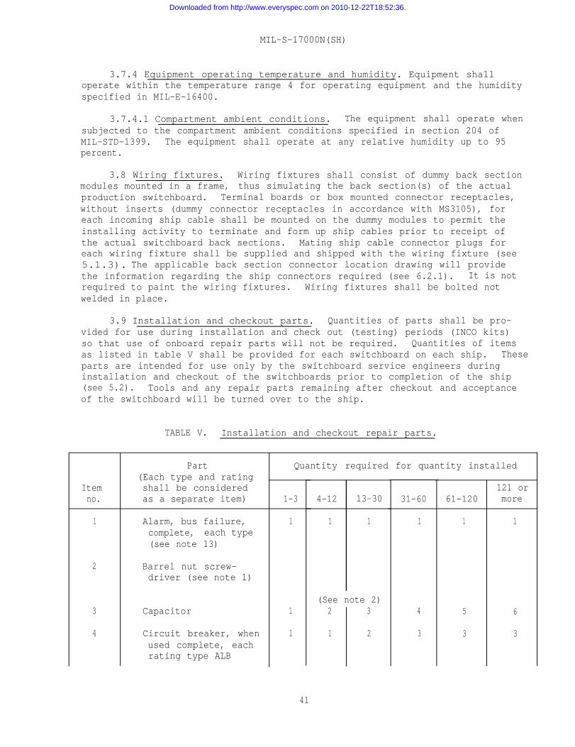
MIL-S-17000N(SH)
3.7.4 Equipment operating temperature and humidity. Equipment shalloperate within the temperature range 4 for operating equipment and the humidityspecified in MIL-E-16400.
3.7.4.1 Compartment ambient conditions. The equipment shall operate whensubjected to the compartment ambient conditions specified in section 204 ofMIL-STD-1399. The equipment shall operate at any relative humidity up to 95percent.
3.8 Wiring fixtures. Wiring fixtures shall consist of dummy back sectionmodules mounted in a frame, thus simulating the back section(s) of the actualproduction switchboard. Terminal boards or box mounted connector receptacles,without inserts (dummy connector receptacles in accordance with MS3105), foreach incoming ship cable shall be mounted on the dummy modules to permit theinstalling activity to terminate and form up ship cables prior to receipt ofthe actual switchboard back sections. Mating ship cable connector plugs foreach wiring fixture shall be supplied and shipped with the wiring fixture (see5.1.3). The applicable back section connector location drawing will providethe information regarding the ship connectors required (see 6.2.1). It is notrequired to paint the wiring fixtures. Wiring fixtures shall be bolted notwelded in place.
3.9 Installation and checkout parts. Quantities of parts shall be pro-vided for use during installation and check out (testing) periods (INCO kits)so that use of onboard repair parts will not be required. Quantities of itemsas listed in table V shall be provided for each switchboard on each ship. Theseparts are intended for use only by the switchboard service engineers duringinstallation and checkout of the switchboards prior to completion of the ship(see 5.2). Tools and any repair parts remaining after checkout and acceptanceof the switchboard will be turned over to the ship.
Itemno.
1
2
3
4
TABLE V. Installation and checkout repair parts.
Part(Each type and ratingshall be consideredas a separate item)
Alarm, bus failure,complete, each type(see note 13)
Barrel nut screw-driver (see note 1)
Capacitor
Circuit breaker, whenused complete, eachrating type ALB
Quantity required
1-3
1
1
1
4-12 13-30
1 1
(See note 2)2 3
1 2
for quantity installed
31-60
1
4
3
61-120
1
5
3
121 ormore
1
6
3
41
Downloaded from http://www.everyspec.com on 2010-12-22T18:52:36.
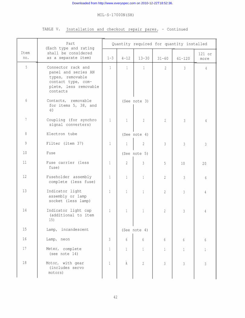
Itemno.
5
6
7
8
9
10
11
12
13
14
15
16
17
18
MIL-S-17000N(SH)
TABLE V. Installation and checkout repair pares. - Continued
Part(Each type and ratingshall be consideredas a separate item)
Connector rack andpanel and series ANtypes, removablecontact type, com-plete, less removablecontacts
Contacts, removablefor items 5, 38, and40
Coupling (for synchrosignal converters)
Electron tube
Filter (item 37)
Fuse
Fuse carrier (lessfuse)
Fuseholder assemblycomplete (less fuse)
Indicator lightassembly or lampsocket (less lamp)
Indicator light cap(additional to item15)
Lamp, incandescent
Lamp, neon
Meter, complete(see note 14)
Motor, with gear(includes servomotors)
Quantity required for quantity installed
1-3
1
1
1
1
1
1
1
3
1
1
4-12
1
13-30
1
(See note 3)
1 2
(See note 4)
1 2
(See note 5)
2
1
1
1
3
1
1
1
(See note 4)
6
1
1A
6
1
2
31-60
2
2
3
5
2
2
2
6
1
3
61-120
3
3
3
10
3
3
3
6
1
3
121 ormore
4
4
3
20
6
4
4
6
1
3
42
Downloaded from http://www.everyspec.com on 2010-12-22T18:52:36.
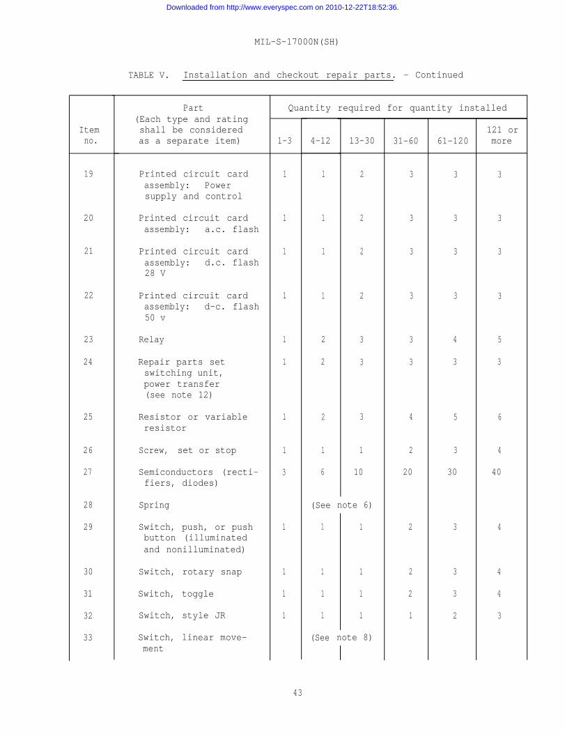
Itemno.
19
20
21
22
23
24
25
26
27
28
29
30
31
32
33
MIL-S-17000N(SH)
TABLE V. Installation and checkout repair parts. - Continued
Part(Each type and ratingshall be consideredas a separate item)
Printed circuit cardassembly: Powersupply and control
Printed circuit cardassembly: a.c. flash
Printed circuit cardassembly: d.c. flash28 V
Printed circuit cardassembly: d-c. flash50 v
Relay
Repair parts setswitching unit,power transfer(see note 12)
Resistor or variableresistor
Screw, set or stop
Semiconductors (recti-fiers, diodes)
Spring
Switch, push, or pushbutton (illuminatedand nonilluminated)
Switch, rotary snap
Switch, toggle
Switch, style JR
Switch, linear move-ment
Quantity required for quantity installed
1-3
1
1
1
1
1
1
1
1
3
1
1
1
1
4-12
1
1
1
1
2
2
2
1
6
(See
1
1
1
1
(See
13-30
2
2
2
2
3
3
3
1
10
note 6)
1
1
1
1
note 8)
31-60
3
3
3
3
3
3
4
2
20
2
2
2
1
61-120
3
3
3
3
4
3
5
3
30
3
3
3
2
121 ormore
3
3
3
3
5
3
6
4
40
4
4
4
3
43
Downloaded from http://www.everyspec.com on 2010-12-22T18:52:36.
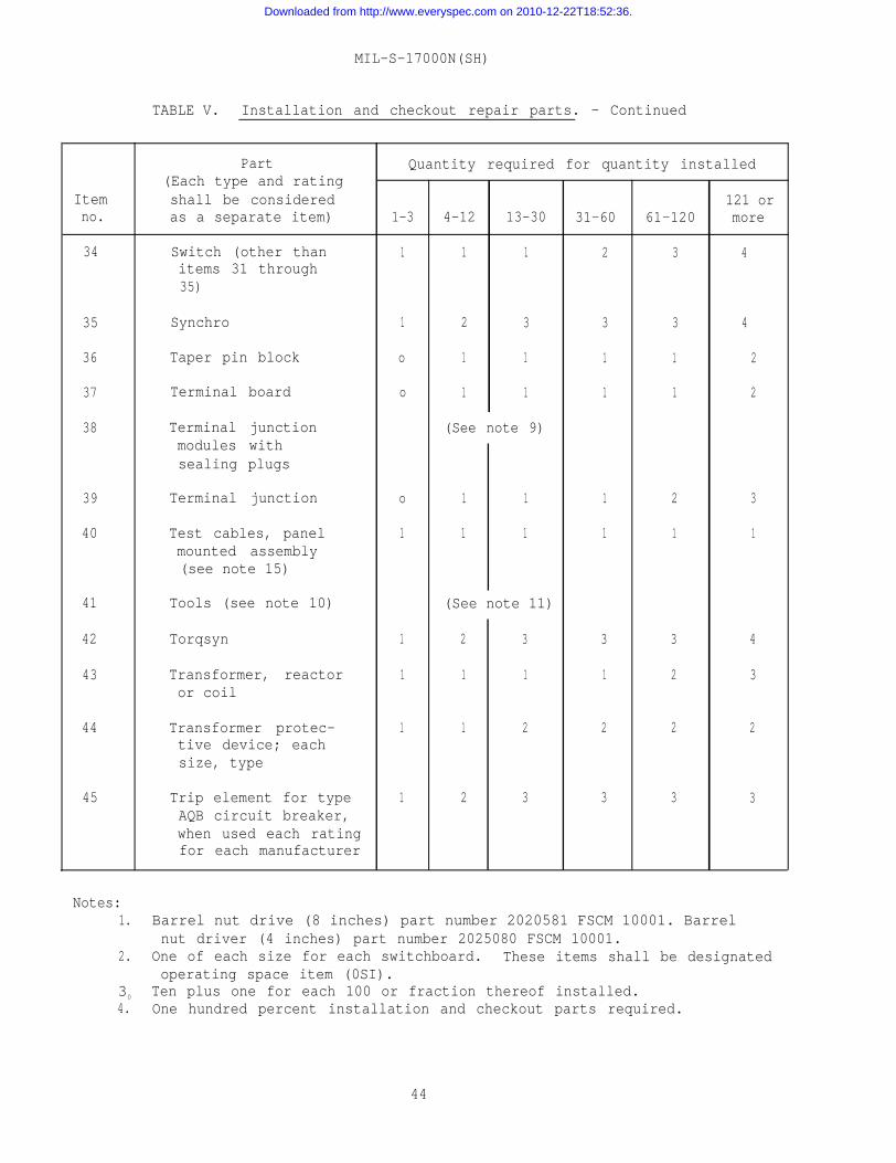
MIL-S-17000N(SH)
TABLE V. Installation and checkout repair parts. - Continued
Part Quantity required for quantity installed(Each type and rating
Item shall be considered 121 orno. as a separate item) 1-3 4-12 13-30 31-60 61-120 more
34 Switch (other than 1 1 1 2 3 4items 31 through35)
35 Synchro 1 2 3 3 3 4
36 Taper pin block o 1 1 1 1 2
37 Terminal board o 1 1 1 1 2
38 Terminal junction (See note 9)modules withsealing plugs
39 Terminal junction o 1 1 1 2 3
40 Test cables, panel 1 1 1 1 1 1mounted assembly(see note 15)
41 Tools (see note 10) (See note 11)
42 Torqsyn 1 2 3 3 3 4
43 Transformer, reactor 1 1 1 1 2 3or coil
44 Transformer protec- 1 1 2 2 2 2tive device; eachsize, type
45 Trip element for type 1 2 3 3 3 3AQB circuit breaker,when used each ratingfor each manufacturer
Notes:1. Barrel nut drive (8 inches) part number 2020581 FSCM 10001. Barrel
nut driver (4 inches) part number 2025080 FSCM 10001.2. One of each size for each switchboard. These items shall be designated
operating space item (0SI).30 Ten plus one for each 100 or fraction thereof installed.4. One hundred percent installation and checkout parts required.
44
Downloaded from http://www.everyspec.com on 2010-12-22T18:52:36.
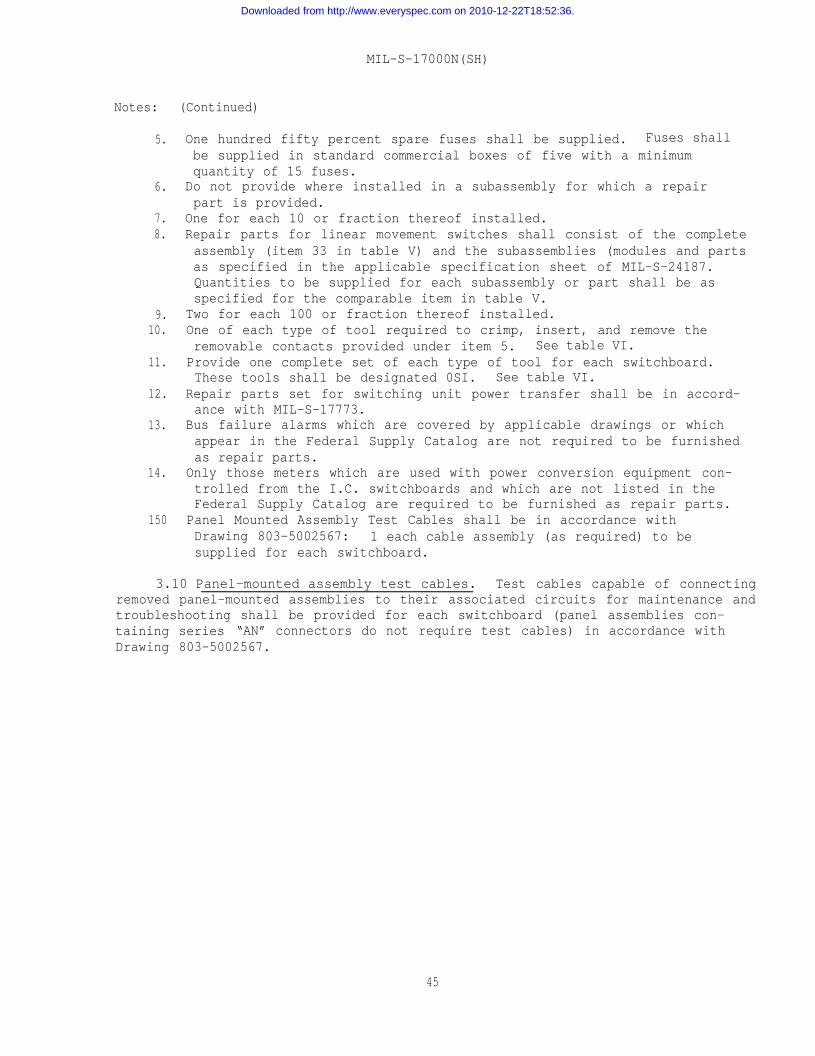
MIL-S-17000N(SH)
Notes: (Continued)
5.
6.
7.8.
9.10.
11.
12.
13.
14.
150
One hundred fifty percent spare fuses shall be supplied. Fuses shallbe supplied in standard commercial boxes of five with a minimumquantity of 15 fuses.
Do not provide where installed in a subassembly for which a repairpart is provided.
One for each 10 or fraction thereof installed.Repair parts for linear movement switches shall consist of the completeassembly (item 33 in table V) and the subassemblies (modules and partsas specified in the applicable specification sheet of MIL-S-24187.Quantities to be supplied for each subassembly or part shall be asspecified for the comparable item in table V.
Two for each 100 or fraction thereof installed.One of each type of tool required to crimp, insert, and remove theremovable contacts provided under item 5. See table VI.Provide one complete set of each type of tool for each switchboard.These tools shall be designated 0SI. See table VI.
Repair parts set for switching unit power transfer shall be in accord-ance with MIL-S-17773.
Bus failure alarms which are covered by applicable drawings or whichappear in the Federal Supply Catalog are not required to be furnishedas repair parts.
Only those meters which are used with power conversion equipment con-trolled from the I.C. switchboards and which are not listed in theFederal Supply Catalog are required to be furnished as repair parts.
Panel Mounted Assembly Test Cables shall be in accordance withDrawing 803-5002567: 1 each cable assembly (as required) to besupplied for each switchboard.
3.10 Panel-mounted assembly test cables. Test cables capable of connectingremoved panel-mounted assemblies to their associated circuits for maintenance andtroubleshooting shall be provided for each switchboard (panel assemblies con-taining series “AN” connectors do not require test cables) in accordance withDrawing 803-5002567.
45
Downloaded from http://www.everyspec.com on 2010-12-22T18:52:36.
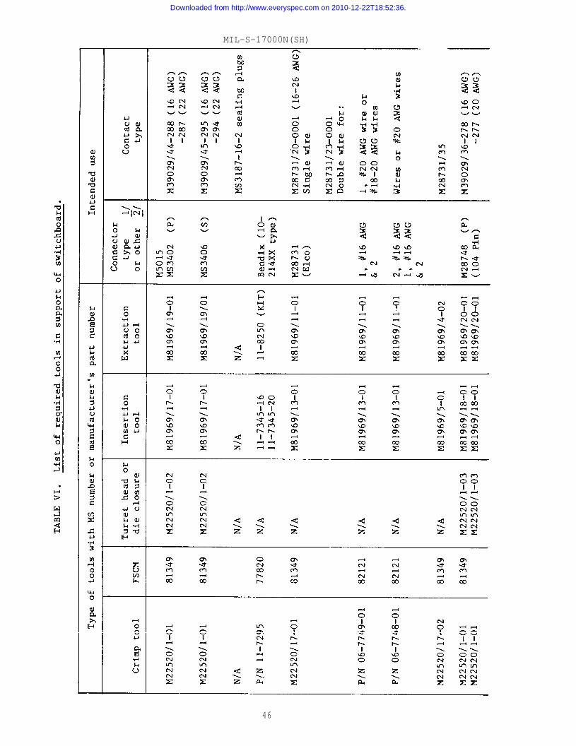
MIL-S-17000N(SH)
46
Downloaded from http://www.everyspec.com on 2010-12-22T18:52:36.
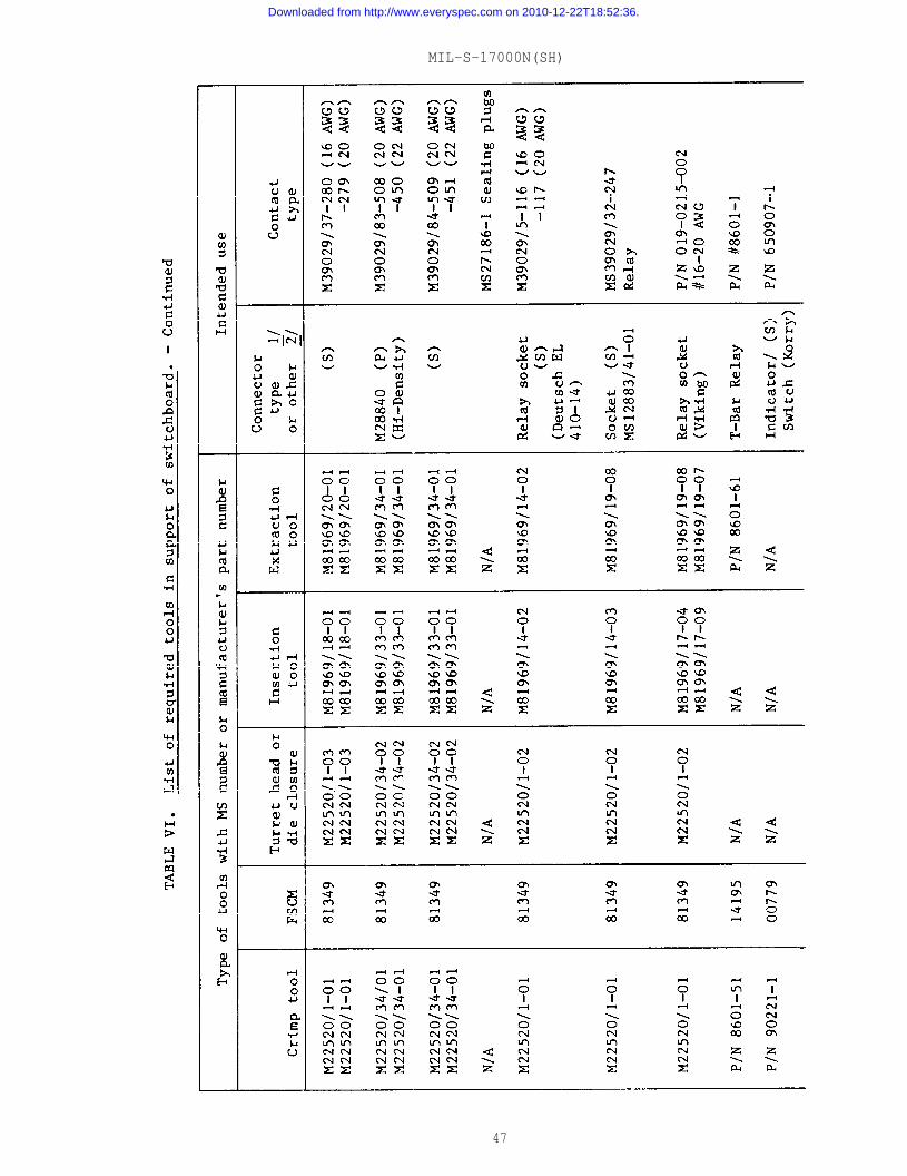
MIL-S-17000N(SH)
47
Downloaded from http://www.everyspec.com on 2010-12-22T18:52:36.
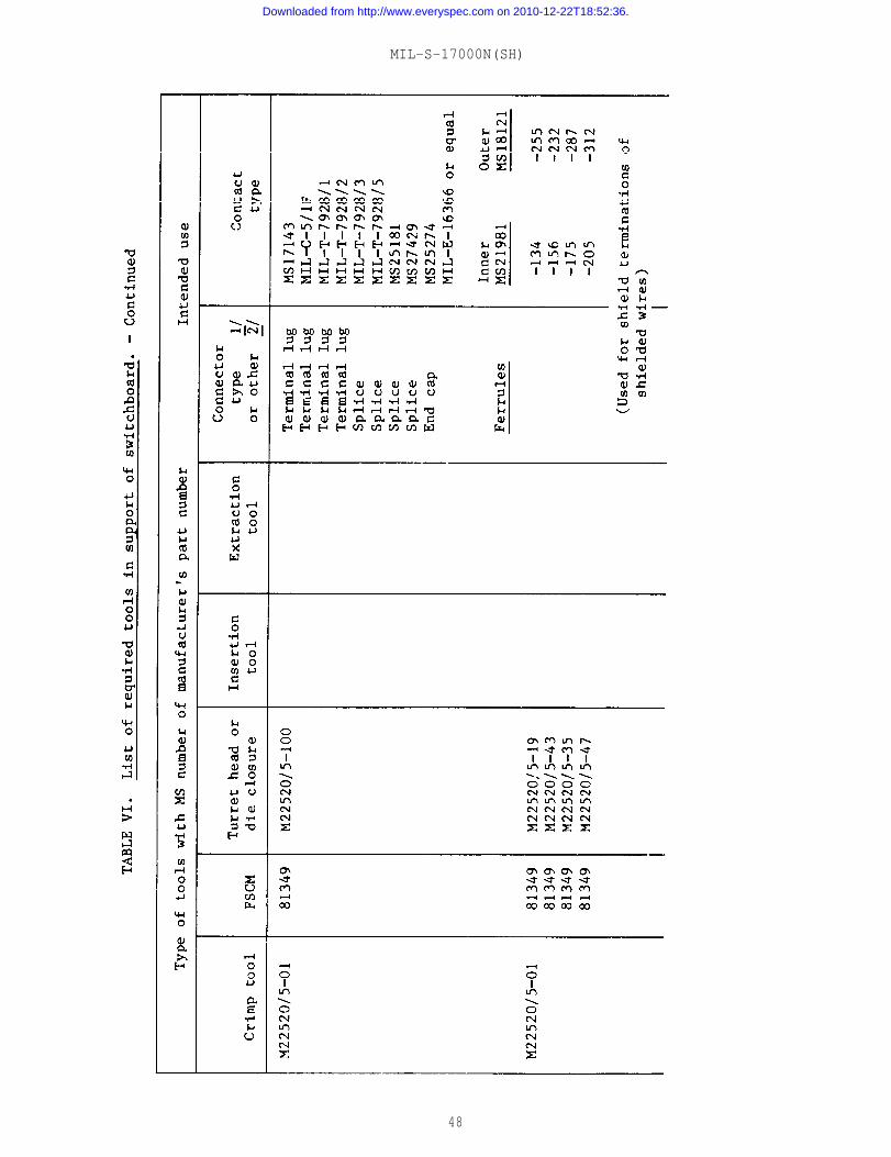
MIL-S-17000N(SH)
48
Downloaded from http://www.everyspec.com on 2010-12-22T18:52:36.

MIL-S-17000N(SH)
49
Downloaded from http://www.everyspec.com on 2010-12-22T18:52:36.
MIL-S-17000N(SH)
3.11 Services. When specified (see 6.2.1), the services of a competentengineer shall be furnished for checking and placing switching equipment in asatisfactory operating condition. Due to the complicated nature of the systemsinvolved, these services are considered essential, and special attention isinvited to this requirement. The establishment of a competent engineeringservice department will be considered as a condition precedent to bidding onswitching equipment. The Government may conduct such investigations as maybe considered necessary to establish the competency of engineering services ofa contractor. Travel orders of field engineers shall contain informationsimilar to figure 5. These services shall consist of the following:
(a)
(b)
(c)
(d)
(e)
(f)
Installing connecting wiring between front and back sectionsand between the sections of a switchboard (preformed factorywiring).
Ensuring proper operation of switchboard equipment (remoteoperated switches, relays and power supplies).
Correction of switchboard manufacturing errors which may existin spite of thorough checking of drawings and equipment.
Installing system changes which occur in the late stages of theoverall control system installation and which timewise cannotbe immediately incorporated in the manufacturer’s drawings norin the switchboard prior to the system circuit tests.
Modifying wiring as necessary during the system circuit test toensure compatibility with control system equipment. Thesechanges occur because of the on-the-spot changes by equipmentmanufacturer’s engineers to make individual control systemsequipment function properly. Such changes shall be recordedby the engineer at the time of the change and both the con-tractor and the contracting officer shall be immediatelyinformed of the changes in order to ensure the accuracy ofswitchboard documentation.
Ensuring that a complete, up-to-date set of the electricaldrawings in 6.5.9.1 through 6.5.9.7 for each switchboard ismade available to the ship just prior to the builder’s trials.These prints shall be obtained from the reproducible copiesprovided the installing activity and marked up to include anychanges made during the last stages of completion of the ship.
3.11.1 Engineering service reports shall be prepared in accordance withthe data ordering document included in the contract (see 6.2.2). An engineeringservice report shall be prepared for each trip made in connection with switch-board modifications of other services relating to installation, checkout, ortests of switching equipment. The report shall be submitted as specified in thedata ordering document included in the contract or order. In the event thatservices exceed one week, a weekly report shall be submitted within one weekafter the end of the work week. Reports shall contain the following informationsubmitted on a form similar to figure 6.
(a) Activity visited.(b) Dates and times of arrival and departure.(c) Description of work accomplished (for example, routine checkout,
installed Field Change No. , dressed switchboards, clearedcasualties or corrected discrepancies found during shipboard
50
Downloaded from http://www.everyspec.com on 2010-12-22T18:52:36.
MIL-S-17000N(SH)
system circuit test), with a narrative technical report onproblems encountered (such as improper installation orconnection of ship wiring, damage to switchboard duringinstallation, missing or delayed material that is affectingcompletion of modifications), recommendations made or actionstaken for their solution.
(d) Authority for trip, types of hours worked, contract number,ship(s) worked on.
3.11.2 A monthly engineering service report on the status of unexpectedservices shall be submitted by the manufacturer prior to the 10th day of thesucceeding month containing the following information:
(a) Amount of engineering services and support (overtime, travel,subsistence) under the contract.
(b) Amount of engineering services and support expended at eachactivity on a weekly basis, for the period covered by the report.
(c) The unexpended balance of engineering service time and supportremaining under the contract.
3.12 Drawings. The contractor shall prepare drawings in accordance withthe data ordering documents included in the contract or order (see 6.2.2). Inaddition to the drawing content required by the data order documents (see6.2.2), the features specified in 3.12.1 through 3.12.1.6 shall be included.A complete set of drawings shall be submitted. Drawings previously submittedunder earlier contracts may be used whenever applicable, but shall be re-submittedfor approval under the instant contract.
3.12.1 Mechanical drawings. The contractor shall prepare drawings asspecified in 3.12.1.1 through 3.12.1.6 covering the mechanical features of theswitchboard to
(a)
(b)
(c)
3.12.1.1
provide the following information:
To permit the contracting activity to determine that theswitchboard design complies with the requirements of this specification and when applicable to document switchboarddesigns submitted for qualification testing.
To provide the installing activity with accurate informationregarding mounting bolt hole and sway brace bolt hole locations.
To provide maintenance and supply activities with detail infor-mation regarding parts used in the switchboard and to determinethe interchangeability of the various panel-mounted assemblies.
Mechanical assembly drawing. Mechanical assembly drawing shallinclude dimensioned outline front view, plan view, end views, and such otherviews as are required to show clearly the details of mechanical design, con-struction, and assembly of one complete switchboard section. An assemblydrawing shall also be prepared for a control indicator. This drawing shall betitled “Type 11 switchboard section assembly” for example.
51
Downloaded from http://www.everyspec.com on 2010-12-22T18:52:36.
MIL-S-17000N(SH)
3.12.1.2 Switchboard overall assembly drawing. Overall assembly drawingshall show the overall dimensions, foundation bolt hole locations, and clearancesrequired for the complete switchboard. Weight and location of the center ofgravity of the switchboard, the location of the sway brace mounting holes,heat dissipation, and location and purpose of the connector box for the internallight shall be shown on this drawing. When applicable, the Mark and Mod numberof the switchboard shall be shown. Parts list shall identify each panel-mountedassembly installed in the switchboard. Diameter, type, quantity, and torquevalues required for foundation and intersection fastening hardware shall beS hewn . A note for the installing activity shall reference Publication NAVSEA SE670-FO-MMD-010/Swbds for installation criteria. A separate drawing shall beprepared for each different switchboard, each control indicator, or each remoteoperated switch assembly on each contract.
3.12.1.3 Panel-mounted assemblies. These drawings shall depict the mechani-cal design, construction, and assembly of panel-mounted assemblies, includingbasic or blank panel assemblies. These drawings shall include views depictingparts and a tabulation of the specific parts for each panel-mounted assembly.Marking information of description plates shall be shown either on the individualassembly drawing or on a combined marking information drawing. Overall dimensionsof the assembly shall be shown.
3.12.1.4 Subassemblies and mechanical details. Drawings shall be preparedto show the complete details of parts (such as designation plates, front panel,and chassis) and assemblies such as module assemblies that are not clearly shownon other drawings. Overall dimensions of each subassembly shall be shown inaddition to these details. Parts from vendors, when shown as part of a sub-assembly shall be listed as independent items on the parts list.
3.12.1.5 Part identification. Each replaceable part shall be identifiedwith the following and include the maximum information that may be necessary todefine the required data on at least one of the drawings specified in 3.12.1.1through 3.12.1.4.
(a)(b)(c)
(d)(e)
(f)(g)(h)
Nomenclature or description.Military part number.Part or identifying number as used by the actual manufacturerof the part (not the switchboard manufacturers part numberunless the part is made by the switchboard manufacturer).
Actual manufacturer’s name or code identification number.Government specification number or MS sheet number (for example)(or commercial designations where there is no applicableGovernment specification).
Material (unless the item is an assembly using several materials).Mechanical, electrical, and physical characteristics.National stock number (if available).
The above information may be tabulated in a parts list on an assembly or sub-assembly drawing (such as a switch assembly or module assembly) or shown on thedetail drawing of the part. Where several assemblies requiring varying numbersof the same parts are shown on a drawing, each part shall be listed only oncein the parts list, each assembly shall be assigned a number and the “No. Reqd.”
52
Downloaded from http://www.everyspec.com on 2010-12-22T18:52:36.
MIL-S-17000N(SH)
column shall be replaced by a “No. Reqd. for No. “ column for each assembly.The unit weight and stock number need not be listed Each wire type and theapproximate total length of each type used shall be listed.
3.12.1.6 Parts list (parts population). Manufacturer shall prepare atabulation of parts used on the switchboards being furnished on the contract.This tabulation shall show the quantities used on each individual switchboard.
3.12.2 Preparation of drawings. In addition to the requirements of thedata ordering documents, the features specified in 3.12.2.1 through 3. 12.2.5.5shall be included in the drawings specified in 3.12.1.1. through 3.12.1.6.
3.12.2.1 Size. The maximum size of original drawings shall be size Hwith a maximum length of 88 inches. All sheets of a multisheet drawing shallbe the same size. Size E drawings shall not be used. (See ANSI Y14.1 fordescription of size E and H drawings.)
3.12.2.2 Prints for submittal. Prints made to be submitted for approvalshall be approximately 11 by 34 inches with borders not less than 10-1/2inches high.
3.12.2.3 Detail accuracy. Drawings of assemblies or subassemblies shallbe correct in content and details to permit checking for interference or mis-mating or working parts.
3.12.2.4 Drawing numbering and titles. All sheets of a multisheet drawingshall have the same basic title. Subtitles may be used on other than the firstsheet to locate major features. The title shall clearly indicate the infor-mation shown on the drawing. Multisheet drawings shall bear the same drawingnumber followed by sheet 1, sheet 2, sheet 3, and so on. Only the first sheetshall show the total number of sheets. Drawing numbers assigned by the manu-facturer shall not contain prefix or suffix letters that could be confused withdrawing size or revision letters. The first sheet of multisheet drawings shallinclude a tabulation “Revision status of sheets” showing the revision letterof each sheet. This tabulation shall be located immediately over the titleblock. Title blocks of continuation sheets shall be in accordance with ANSIY14.1.
3.12.2.5 Revision of drawings.
3.12.2.5.1 Revision of a drawing will be issued as a Notice of Revision(NOR) showing only the area of the drawing affected by the change in the contractor order (see 6.2.2).
3.12.2.5.2 The revision block of revised drawings shall show the basicauthority for the change. The “Revision status of sheets” block (see 3.12.2.4)shall show the revision status of each sheet.
3.12.2.5.3 Drawings shall be revised prior to modification of the equip-ment and submitted as specified in the contract prior to their release for usein modifying the equipment. For urgent modifications of equipment, authorityto proceed with the work prior to drawing revision shall be obtained from thecontracting activity. Where drawings are "approved subject to modifications”,they shall be revised and distributed for information to the destinations
53
Downloaded from http://www.everyspec.com on 2010-12-22T18:52:36.
MIL-S-17000N(SH)
specified in the contract. Where an Engineering Change Proposal (ECP) isauthorized for use on a contract, all drawings affected shall be revised andresubmitted for approval to the destinations specified in the contract ororder (see 6.2.2). After drawings have been approved, no changes shall beinitiated by the contractor without resubmission of the revised drawing forapproval of the change. Where drawings are revised for reasons other thanauthorized modification (such as developments necessary to comply with theintent of the contract, for proper and satisfactory completion of the contract,contractor initiated design improvements or simplification for manufacturingpurposes), the letter forwarding the revised drawings shall cite the approvedECP which covers the modification.
3.12.2.5.4 The file number, serial number, and date of acceptance lettershall be entered in the revision column of the drawings. The drawings shallthen be redistributed in accordance with the requirements of the contract.
3.12.2.5.5 The record of previous revisions on drawings shall be retainedwhen these drawings are revised for final delivery in the contract or order(see 6.2.2).
3.13 Workmanship. Workmanship shall be in accordance with requirement 9of MIL-STD-454.
4. QUALITY ASSURANCE PROVISIONS
4.1 Responsibility for inspection. Unless otherwise specified in the con-tract or purchase order, the contractor is responsible for the performance ofall inspection requirements as specified herein. Except as otherwise specifiedin the contract or purchase order, the contractor may use his own or any otherfacilities suitable for the performance of the inspection requirements specifiedherein, unless disapproved by the Government. The Government reserves the rightto perform any of the inspections set forth in the specification where suchinspections are deemed necessary to assure that the supplies and services conformto prescribed requirements.
4.1.1 Quality program. The contractor shall provide and maintain aquality program acceptable to the Government for supplies and services coveredby this specification as specified in the contract or order (see 6.2.1).
4.2 Classification of inspection. The inspection requirements specifiedherein are classified as follows:
(a) Qualification inspection (see 4.3).(b) Quality conformance inspection (see 4.4).
4.3 Qualification inspection. Qualification inspection shall be con-ducted at a laboratory satisfactory to NAVSEA. Qualification inspectionshall consist of the examination and tests shown in table VII.
54
Downloaded from http://www.everyspec.com on 2010-12-22T18:52:36.
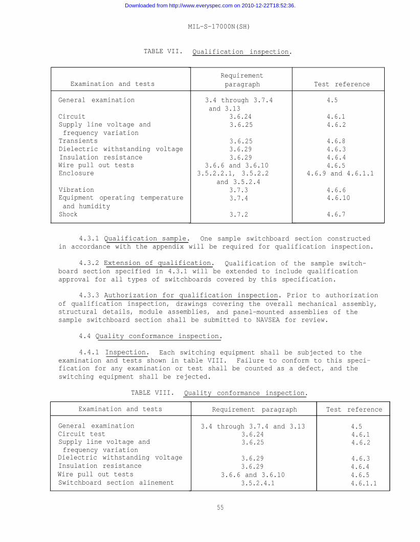
MIL-S-17000N(SH)
TABLE VII. Qualification inspection.
Examination and tests
General examination
CircuitSupply line voltage andfrequency variation
TransientsDielectric withstanding voltageInsulation resistanceWire pull out testsEnclosure
VibrationEquipment operating temperatureand humidity
Shock
Requirementparagraph
3.4 through 3.7.4and 3.13
3.6.243.6.25
3.6.253.6.293.6.29
3.6.6 and 3.6.103.5.2.2.1, 3.5.2.2
and 3.5.2.43.7.33.7.4
3.7.2
Test reference
4.5
4.6.14.6.2
4.6.84.6.34.6.44.6.5
4.6.9 and 4.6.1.1
4.6.64.6.10
4.6.7
4.3.1 Qualification sample. One sample switchboard section constructedin accordance with the appendix will be required for qualification inspection.
4.3.2 Extension of qualification. Qualification of the sample switch-board section specified in 4.3.1 will be extended to include qualificationapproval for all types of switchboards covered by this specification.
4.3.3 Authorization for qualification inspection. Prior to authorizationof qualification inspection, drawings covering the overall mechanical assembly,structural details, module assemblies, and panel-mounted assemblies of thesample switchboard section shall be submitted to NAVSEA for review.
4.4 Quality conformance inspection.
4.4.1 Inspection. Each switching equipment shall be subjected to theexamination and tests shown in table VIII. Failure to conform to this speci-fication for any examination or test shall be counted as a defect, and theswitching equipment shall be rejected.
TABLE VIII. Quality conformance inspection.
Examination and tests
General examinationCircuit testSupply line voltage andfrequency variation
Dielectric withstanding voltageInsulation resistanceWire pull out testsSwitchboard section alinement
Requirement paragraph
3.4 through 3.7.4 and 3.133.6.243.6.25
3.6.293.6.29
3.6.6 and 3.6.103.5.2.4.1
55
Test reference
4.54.6.14.6.2
4.6.34.6.44.6.54.6.1.1
Downloaded from http://www.everyspec.com on 2010-12-22T18:52:36.
MIL-S-17000N(SH)
4.4.2 Test conditions. Except for those tests where the followingfactors are the variables, tests shall be conducted with the equipment operat-ing under the following conditions:
(a) Ambient temperature and humidity shall be between 70 and 80°Fand the relative humidity shall be between 25 and 50 percent.
(b) Supply voltage shall be the nominal operating voltage.(c) Supply frequency shall be the nominal operating frequency.
4.5 General examination. The completed unit shall be given a thoroughexamination to determine that it conforms to the applicable specification anddrawings with respect to material, finish, workmanship, construction, assembly,dimensions, weight, and marking of identification and description plates. Thisexamination shall be limited to those that can be performed without disassemblingthe unit in such a manner that its performance, durability, or appearance wouldbe affected. This examination shall include a check of operating controls,circuit functions, synchro connections for compliance with requirement 2 ofMIL-STD-1657, test facilities, and adjustments, as applicable.
4.6 Tests.
4.6.1 Circuit tests. Circuit tests shall be performed by the use ofappropriate test equipments. Tests specified in 4.6.3 and 4.6.4 (dielectricwithstanding voltage and insulation resistance tests) may also be performed bythis test equipment during the circuit tests (see 4.6.3.1). When used fortests outlined in 4.6.1.1, the test equipment shall be connected to the shipwire terminals or ship cable connectors on the modules. Remote operated switchassemblies, relays, flasher, and similar items, shall be electrically operatedat least ten times, either during production tests on the individual items oras part of the hot tests required in 4.6.1.1(b). These tests shall be con-ducted to ensure that short circuits are not present in the equipment.
4.6.1.1 Switchboards. Each switchboard of one or more sections shall becompletely assembled and interconnected and tested for the features listed below:
(a) “Cold’* tests. Continuity shall be checked for circuits thatdo not connect to a conversion device (such as a signalgenerator, transformer, or synchro signal converter) todetermine that the signals are transmitted in accordancewith the requirements specified on the detail schematicwiring diagrams. Discontinuity shall be checked byrepositioning switches and removing fuses in the circuitto verify power interruption in accordance with the require-ments specified on the detail schematic wiring diagrams.The circuits shall be tested to ground to verify properisolation from ground.
(b) “Hot” tests. Operation of switchboard units and relatedcircuitry (such as remote operated switch assemblies, relays,signal generators, meters, lights, power supplies, flashers)and synchro signal converters) shall be checked to verifyproper operation of the unit and related circuitry in accord-ance with the requirements specified on the detail schematic
56
Downloaded from http://www.everyspec.com on 2010-12-22T18:52:36.
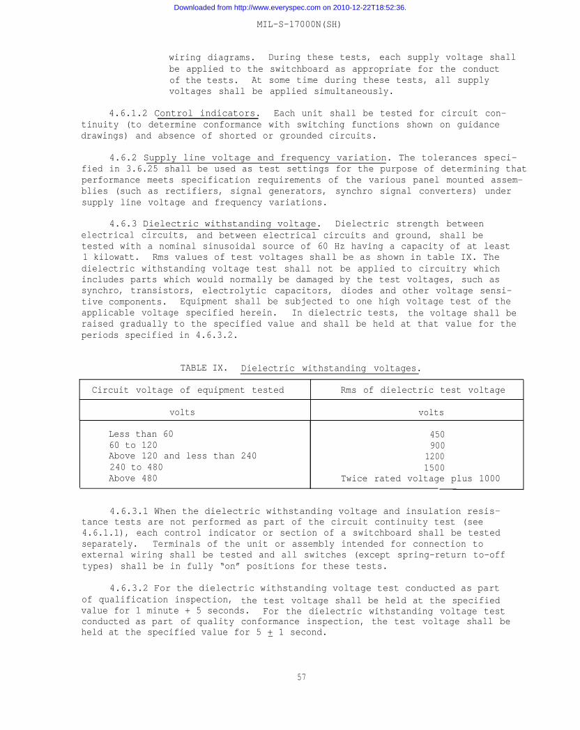
MIL-S-17000N(SH)
wiring diagrams. During these tests, each supply voltage shallbe applied to the switchboard as appropriate for the conductof the tests. At some time during these tests, all supplyvoltages shall be applied simultaneously.
4.6.1.2 Control indicators. Each unit shall be tested for circuit con-tinuity (to determine conformance with switching functions shown on guidancedrawings) and absence of shorted or grounded circuits.
4.6.2 Supply line voltage and frequency variation. The tolerances speci-fied in 3.6.25 shall be used as test settings for the purpose of determining thatperformance meets specification requirements of the various panel mounted assem-blies (such as rectifiers, signal generators, synchro signal converters) undersupply line voltage and frequency variations.
4.6.3 Dielectric withstanding voltage. Dielectric strength betweenelectrical circuits, and between electrical circuits and ground, shall betested with a nominal sinusoidal source of 60 Hz having a capacity of at least1 kilowatt. Rms values of test voltages shall be as shown in table IX. Thedielectric withstanding voltage test shall not be applied to circuitry whichincludes parts which would normally be damaged by the test voltages, such assynchro, transistors, electrolytic capacitors, diodes and other voltage sensi-tive components. Equipment shall be subjected to one high voltage test of theapplicable voltage specified herein. In dielectric tests, the voltage shall beraised gradually to the specified value and shall be held at that value for theperiods specified in 4.6.3.2.
TABLE IX. Dielectric withstanding voltages.
Circuit voltage of equipment tested Rms of dielectric test voltage
volts volts
Less than 60 45060 to 120 900Above 120 and less than 240 1200240 to 480 1500Above 480 Twice rated voltage plus 1000
4.6.3.1 When the dielectric withstanding voltage and insulation resis-tance tests are not performed as part of the circuit continuity test (see4.6.1.1), each control indicator or section of a switchboard shall be testedseparately. Terminals of the unit or assembly intended for connection toexternal wiring shall be tested and all switches (except spring-return to-offtypes) shall be in fully “on” positions for these tests.
4.6.3.2 For the dielectric withstanding voltage test conducted as partof qualification inspection, the test voltage shall be held at the specifiedvalue for 1 minute + 5 seconds. For the dielectric withstanding voltage testconducted as part of quality conformance inspection, the test voltage shall beheld at the specified value for 5 + 1 second.—
57
Downloaded from http://www.everyspec.com on 2010-12-22T18:52:36.
MIL-S-17000N(SH)
4.6.4 Insulation resistance test. Insulation resistance of electricalcircuits following the dielectric withstanding voltage test specified in 4.6.3shall be tested at 50 V d.c. at room ambient temperature and humidity to deter-mine conformance with 3.6.29. Insulation resistance test voltage shall not beapplied to circuitry which includes parts which would normally be damaged bythe test voltage, such as synchro, transistors, electrolytic capacitors, diodesand other voltage sensitive components.
4.6.5 Wire pullout tests. Daily production check tests of the quality ofcrimped connections for connector contacts and solderless wire terminal lugsshall be made. Approximately ten crimps of each type (connector or wire terminal)made each day shall be checked for pullout (crimp, tensile strength) in accord-ance with MIL-C-28731, MIL-C-39029, MIL-T-16366, or MIL-T-7928, as applicable.
4.6.6 Vibration test. Vibration test to determine conformance with 3.7.3shall be conducted in accordance with type I (environmental vibration) ofMIL-STD-167-1, except that the variable-frequency test shall be omitted. Afterthe tests, the circuits shall be checked to ensure proper operation and con-tinuity (see 6.2.2).
4.6.7 Shock test. Shock test to determine conformance with 3.7.2 shall beconducted in accordance with type A, class I of MIL-S-901. After the tests, thecircuits shall be checked to ensure proper operation and continuity. Units whichhave been subjected to the shock test shall not be installed on board ship.A shock test report shall be prepared in accordance with the data orderingdocument included in the contract or order (see 6.2.2).
4.6.8 Transient test. A l-millisecond pulse of a magnitude sufficient toprovide 300 percent over voltage of the peak supply voltage shall be super-imposed on the nominal supply voltage to the switchboard. The output of theequipment power supply shall be observed on a calibrated oscilloscope todetermine conformance with 3.6.25. With a constant power supply input, theoutput of the equipment power supply shall be observed on a calibrated oscillo-scope, while the equipment is switched through all operational modes to determineconformance with 3.6.25.
4.6.9 Enclosure test. Watertight requirements shall be subjected to thetest conditions in MIL-STD-108, except that the requirement for breaking andreassembling joints sealed by gaskets prior to test applies only to cover ordoor openings, not indicator or observation windows. Dripproof enclosuresshall be visually examined to verify that the unit conforms to the applicableassembly drawing.
4.6.10 Equipment operating temperatures. The applicable component speci-fications (for example, MIL-S-24187) shall be reviewed to verify that the variouscomponents have been operated at temperatures and humidities equal to or exceedingthose specified for temperature range 4 for operating equipment in MIL-E-16400.
4.6.11 Geometric control of enclosures. After completion of the installa-tion of all panel assemblies, back section modules, and harness wiring, theindividual front and back sections of each switchboard shall be assembled on acommon foundation. Individual sections shall be bolted to the foundation andto each other using the intersection fastening hardware required to be shipped
58
Downloaded from http://www.everyspec.com on 2010-12-22T18:52:36.
MIL-S-17000N(SH)
with the switchboards. Flatness, perpendicularity, and parallelism of the overallswitchboard shall conform to 3.5.2.2. Assembly procedure outlined in NAVSEA SE670-FO-MMO-O10/Swbds shall be followed.
4.7 Test procedures and test reports. The contractor shall prepare testprocedures and test reports in accordance with the data ordering documentsincluded in the contract or order (see 6.2.2).
4.8 Inspection of packaging. Sample packages and packs and the inspectionof the preservation-packaging, packing, and marking for shipment and storage shallbe in accordance with the requirements of section 5 and documents specifiedtherein.
5. PACKAGING
(The preparation for delivery requirements specified herein apply only fordirect Government acquisition. For the extent of applicability of the prepara-tion for delivery requirements of referenced documents listed in section 2,see 6.4.)
5.1 Switchboards and control indicators. Types II, IV, VI, VII, VIII, IX,X, XI, and XII switchboard sections, types III, V, and XI switchboards, andcontrol indicators shall be prepared for delivery in accordance with the require-ments specified in 5.1.1 through 5.1.2.2 for the level of shipment as specified(see 6.2.1).
5.1.1 Packaging.
5.1.1.1 Level A. Packaging shall be in accordance with submethod IIa ofMIL-P-116. An inspection window shall be required.
5.1.1.2 Level C. Packaging shall protect against corrosion, deterioration,and physical damage during shipment from the supply source to the using activity.
5.1.2 Packing. Types II, IV, VII, VIII, IX, X, and XII switchboards shallbe placed in the shipping containers horizontally or vertically. Type VI switch-board sections may be placed in the shipping containers on a side. Drip shieldsshall be packed with the switchboard.
5.1.2.1 Level A. Each type II, IV, VI, VII, VIII, IX, X, XI, and XIIswitchboards shall be packed horizontally or vertically in boxes conforming totype I of MIL-B-26195. Each box shall be provided with an inspection windowwith readily removable cover opposite the inspection window in the barrier bag(see 5.1.1.1). Each type III, V, and XI switchboard and each control indicatorshall be packed in a box conforming to overseas type of PPP-B-601 or class 2of PPP-B-621.
5.1.2.2 Level C. Types II, IV, VI, VII, VIII, IX, X, XI, and XII switch-boards packaged as specified (see 5.1.1.2), shall be mounted horizontally orvertically on wood shipping skids of a type and style to ensure acceptance bycommon carrier and to permit forklift truck handling from either side. TypeIII, V, and XI switchboards and control indicators shall be packed to ensureacceptance by common carrier and in compliance with the Uniform Freight Clas-sification Ratings, Rules, and Regulations.
59
Downloaded from http://www.everyspec.com on 2010-12-22T18:52:36.
MIL-S-17000N(SH)
5.1.3 Packing of barrel nuts, intersection fastening hardware, and matingship connector plugs. Barrel nuts and connector plugs required for connectionof ship wires to back section terminal boards and connector receptacles, respec-tively, shall be packed in the same box as the associated back section. Barrelnuts shall be packaged in sturdy textile bags, one size per bag. Connector plugsshall be packaged method IC in accordance with MIL-P-116. Intersection fasteninghardware shall be packaged in sturdy textile bags and packed in the same box asthe front section.
5.2 Installation and checkout repair parts. Installation and checkoutrepair parts (INCO KITS) shall be preserved and packaged level A and packedlevel A or C in accordance with the requirements of MIL-STD-794 for the shipmentlevels as specified (see 6.2.1). The level of packaging shall be the same asthat specified for the switchboard or control indicator. Installation andcheckout repair parts shall be packed in a separate shipping container andshipped to the installing activity in care of the Receiving Officer,
5.3 Drawings. Drawings shall be prepared for delivery as specified (see6.2.1).
5.4 Marking. In addition to(see 6.2.1), interior packages andshipment for levels A, B, and C in
6. NOTES
6.1 Intended use. Equipmentinterconnect, protect, and provide
any special marking required by the contractshipping containers shall be marked foraccordance with MIL-STD-129.
covered in this specification is intended tofault isolation in the electrical circuits
of Naval shipboard fire control systems, command and control systems, interiorcommunication systems and combat systems.
6.2 Ordering data.
6.2.1 Acquisition requirements. Acquisition documents should specify thefollowing:
(a)
(b)
(c)(d)(e)(f)
(g)
(h)(i)(j)(k)
Title, number, and date of this specification and the applicablespecification sheet.
Type switchboard (see 1.2.1) and control indicator (see 1.2.2)required (see 3.1).
Number of sections required (see 3.1).Detail mechanical requirements of type IX switchboards (see 3.1).Type of cable entrance required into control indicator (see 3.1).Whether dripproof or watertight requirements is required (see3.5.2.4.2).
Whether a nonstandard (right side) hinge on a switchboardsection door is required (see 3.5.2.7).
Whether a card holder is required (see 3.5.2.13).Whether revision record card is required (see 3.5.10.4).Power supplies and parts required for switchboard (see 3.6.1).Additional master switch requirements (see 3.6.3.11.1).
60
Downloaded from http://www.everyspec.com on 2010-12-22T18:52:36.
(1)
(m)
(n)(o)(p)(q)(r)
(s)
MIL-S-17000N(SH)
Whether provision is to be made for connection of bus failurealarm (see 3.6.4.3).
Whether ships cable connectors are required for control indica-tors (see 3.6.6.3).
Bus bar stresses (see 3.6.23.8).Number of wiring fixtures required, if any (see 3.8).Engineering services required (see 3.11).Quality program in accordance with MIL-Q-9858 (see 4.1.1).Levels of packaging, packing, and marking required (see 5.1, 5.2,5.3, and 5.4).
Listing of applicable electrical drawings to be included in theATDP provided with the IFB (see 6.5.9).
6.2.2 Data requirements. When this specification is used in an acquisitionwhich incorporates a DD Form 1423, Contract Data Requirements List (CDRL), thedata requirements identified below shall be developed as specified by anapproved Data Item Description (DD Form 1664) and delivered in accordance withthe approved CDRL incorporated into the contract. When the provisions of DAR7-104.9 (n)(2) are invoked and the DD Form 1423 is not used, the data speci-fied below shall be delivered by the contractor in accordance with the contractor purchase order requirements. Deliverable data required by this specifica-tion is cited in the following paragraphs.
Paragraph no. Data requirement title Applicable DID no. Option
3.6.2 Nonstandard part approval DI-E-7028 ---requests/proposedadditions to an approvedprogram parts selectionlist
Report, contractor engi-neering and technicalservices (CETS)
Drawings, engineering andassociated lists
3.11.1
3.12
UDI-E-23127
DI-E-7031
---
Level 2Design activitydesignation -contractor
Drawing number -contractor
Delivery of hardcopies - contractingactivity
3.12.2.5.1 Notice of revision/specification changenotice
3.12.2.5.3 Engineering change pro-posals (ECPs) and requestsfor deviations and waivers(long form)
61
DI-E-1126
DI-E-2037
---
---
Downloaded from http://www.everyspec.com on 2010-12-22T18:52:36.
MIL-S-17000N(SH)
Paragraph no.
3.12.2.5.5
4.6.6
4.6.7
4.7
4.7
3.1101
3.11.1
Data requirement title Applicable DID no.
Status summary, engineer- UDI-23149ing change documentation
Report, vibration testing UDI-T-23762
Reports, equipment shock test UDI-T-23753
Procedures, test UDI-T-20503
Reports, test DI-T-2072
Report, failure/malfunction UDI-T-23724
Report, failed item analysis DI-R-7039
Option
---
(Data item descriptions related to this specification, and identified insection 6 will be approved and listed as such in DoD 5000.19L., Vol. II, AMSDL.Copies of data item descriptions required by the contractors in connection withspecific acquisition functions should be obtained from the Naval Publicationsand Forms Center or as directed by the contracting officer.)
6.2.2.1 The data requirements of 6.2.2 and any task in section 3, 4, or 5of this specification required to be performed to meet a data requirement maybe waived by the contracting/acquisition activity upon certification by theofficer that identical data were submitted by the offeror and accepted by theGovernment under a previous contract for identical item acquired to thisspecification. This does not apply to specific data which may be required foreach contract regardless of whether an identical item has been supplied pre-viously (for example, test reports).
6.3 With respect to products requiring qualification, awards will be madeonly for products which are, at the time set for opening of bids, qualified forinclusion in applicable Qualified Products List QPL-17000 whether or not suchproducts have actually been so listed by that date. The attention of the con-tractors is called to these requirements, and manufacturers are urged to arrangeto have the products that they propose to offer to the Federal Government testedfor qualification in order that they may be eligible to be awarded contracts orpurchase orders for the products covered by this specification. The activityresponsible for the Qualified Products List is the Naval Sea Systems Command, SEA5523, Department of the Navy, Washington, DC 20362, and information pertaining toqualification of products may be obtained from that activity. Application forqualification tests shall be made in accordance wit-h “Provisions GoverningQualification SD-6" (see 6.3.1).
6.3.1 Copies of “provisions Governing Qualification SD-6” may be obtainedupon application to Commanding Officer, Naval Publications and Forms Center,5801 Tabor Avenue, Philadelphia, PA 19120.
6.4 Sub-contracted material and parts. The preparation for deliveryrequirements of referenced documents listed in section 2 do not apply whenmaterial and parts are acquired by the contractor for incorporation into theequipment and lose their separate identity when the equipment is shipped.
---
---
---
---
---
---
62
Downloaded from http://www.everyspec.com on 2010-12-22T18:52:36.
MIL-S-17000N(SH)
6.5 Definitions. For the purposes of this specification, the definitionsspecified in 6.5.1 through 6.5.9.8 shall apply.
6.5.1 Switchboard. A switchboard is a device which contains such itemsas switch assemblies, panel assemblies, switches, fuses, monitoring instruments,terminal boards, and wiring with associated framework and enclosure and which isused specifically to energize, switch, protect, and coordinate shipboard controlcircuits or equipment. A switchboard may consist of one or more sections.
6.5.2 Switchboard section. A switchboard section is a self-containedstructure composed of a front section and a back section. The front sectionconsists of a complete framework on which are mounted panels containing equip-ment such as switch assemblies, indicator lights, fuses, relays, and other itemsas required for energizing, protecting, connecting and coordinating shipboardcontrol circuits or equipment. The panels may be mounted on a hinged door withthe connections to the back section made by connectors to the flexible wiringharness. The back section may be separable (for example, attached by bolts)from the front section or it may be a completely separate section. The backsection consists of a complete framework on which are mounted modules con-taining terminal boards or connectors for connecting to ship wiring and con-nectors for connecting to the front section harness wiring.
6.5.2.1 Door. A door is a framework supporting an assembly of switches,indicator lights, relays, and other items that make up a switching system.Its components are connected to ship wiring by means of flexible wiring harnessto the back section modules.
6.5.3 Switch assembly. A switch assembly is a mechanical grouping of oneor more switches associated with accessories, such as remote operating mechanism,wiring, connectors, fuses, and indicator lights. The components may be fixed orjoined into an assembly which may be removed readily as a unit from the parentswitchboard.
6.5.4 Panel assembly. A panel assembly is a mechanical grouping of oneor more components fixed or joined into a unit that may be readily removed fromthe parent switchboard. See MIL-STD-1657 for a description of the types ofpanel assemblies used.
6.5.5 Control indicator. A control indicator is an item which performsthe essential, dual function of presenting visual information from, and regu-lating the mode of operation of, another equipment.
6.5.6 Set-up control system. A set-up control system is one which permitsthe operator to effect any predetermined control switching pattern with oneoperation, such as pushing a button.
6.5.7 Switch, programming. A programming switch is a remote operatedswitch which is positioned by a pushbutton or switch from a remote station andwhich in turn operates other remote operated switch assemblies throughout theship to establish a predetermined control switching pattern. Programmingswitches may be incorporated in switchboards or control indicators.
63
Downloaded from http://www.everyspec.com on 2010-12-22T18:52:36.
MIL-S-17000N(SH)
6.5.8 Description plate. A description plate is a plate that is markedto show panel assembly number, panel assembly nomenclature, and switch operatingposition information. The switch position dial is also a description plate.
6.5.8.1 Revision record card. A revision record card is a descriptionplate that will contain a list of the detail schematic wiring diagrams, thefront panel layout, back section terminal layout or back section connectorlocation drawings with the revision letter of each drawing.
6.5.9 Acquisition technical data package. The Acquisition Technical DataPackage (ATDP) to be provided by the Government with an Invitation for Bids (IFB)will consist of the data list, a set of detail schematic wiring diagrams, thefront panel layout, the back section terminal layout or back section connectorlocation, the wiring details, the parts list (electrical), and a mechanicalguidance drawing. The content and purpose of these drawings is defined in6.5.9.1 through 6.5.9.8. The electrical drawings will contain all terminationdata required to completely wire the switchboard. These drawings will beassigned Government drawing numbers and will be under the configurationcontrol of the Government (see 6.2.1).
6.5.9.1 Data list. The data list provided in the ATDP should be updatedby the switchboard manufacturer to include all drawings applicable to the switch-boards under the contract along with the titles and revision letters of the addeddrawings. Government standard drawings (such as Drawing 815-1853048 covering LSswitches) shall be included.
6.5.9.2 Detail schematic wiring diagrams. Detail schematic wiring dia-grams (DSWD’s) shall be in the form shown in requirement 20 of MIL-STD-1657.DSWD’s shall contain the applicable rear terminal, rear module connector, panelconnector, internal switch contact, internal panel assembly and intersectionconnector-designations for each circuit through the switchboard as describedin requirement 20 of MIL-STD-1657.
6.5.9.3 Front panel layout. Front panel layout drawing shall show thelocation of panel-mounted assemblies on the switchboard. The function of eachpart (fuse, indicator light, relay, transformer, or circuit breaker) and legendof each switch description plate shall be shown.
6.5.9.4 Back section terminal arrangement (types II, III, VI, VIII, X andXI switchboards. Arrangement of back section terminal boards (modules shallshow the position and designation of terminals to which ship wiring is con-nected. Ship wire designations shall be shown with the corresponding terminalboard terminals. Internal switchboard wiring that connects to the back sectionterminal boards shall be shown.
6.5.9.5 Back section connector location.
6.5.9.5.1 Type IV, V, and XII switchboards. This drawing shall show thelocation, shell size, and insert rotation of ship cable connectors for eachsection. The ship cable number and type shall be shown.
64
Downloaded from http://www.everyspec.com on 2010-12-22T18:52:36.
MIL-S-17000N(SH)
6.5.9.5.2 Type VIII switchboards. This drawing shall show the panelnumber and switch assembly connector receptacle number with the correspondingship cable number arranged in panel number sequence.
6.5.9.6 Wiring details. A tabulation shall list each segment of internalswitchboard wiring in a form that can be used to actually wire the switchboard.In addition to the component identification and connection points, this tabula-tion shall include the wire type, size, and color. These tabulations shall bearranged in three groups: the back section module wiring details, the internalwiring details of panel-mounted assemblies other than linear movement switch con-trol circuit wiring (such as meter panels), and harness wiring details frompanel-mounted assembly connectors to module connectors, or other panel-mountedassembly connectors. Internal control circuit wiring details of linear movementswitches are specifically omitted since this wiring is identical for all switches.
6.5.9.7 Parts list (electrical). This drawing shall be a tabulation ofthe electrical parts required in a switchboard such as number and types ofswitches, connectors, fuses, fuseholders, relays, indicator lights, and terminalboards. This drawing is provided for information only.
6.5.9.8 Mechanical guidance drawing. This drawing shall contain require-ments for the mechanical configuration of the switchboard.
6.6 Provisioning. Provisioning Technical Documentation (PTD), spare parts,and repair parts should be furnished as specified in the contract.
6.6.1 When ordering spare parts or repair parts for the equipment coveredby this specification, the contract should state that such spare parts andrepair parts should meet the same requirements and quality assurance provisionsas the parts used in the manufacture of the equipment. Packaging for such partsshould also be specified.
6.7 Cross-reference of classification. Table X lists the switchboard typescovered by the superseded specifications together with the new types covered inthis specification.
65
Downloaded from http://www.everyspec.com on 2010-12-22T18:52:36.
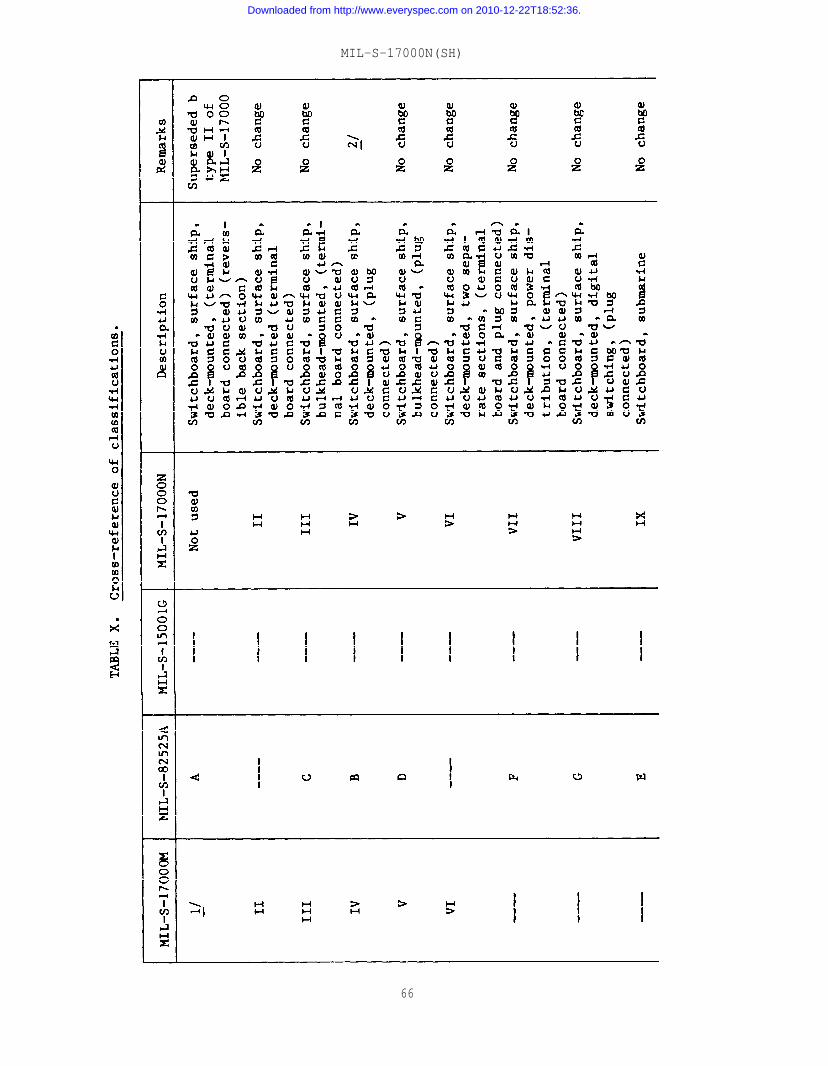
MIL-S-17000N(SH)
66
Downloaded from http://www.everyspec.com on 2010-12-22T18:52:36.
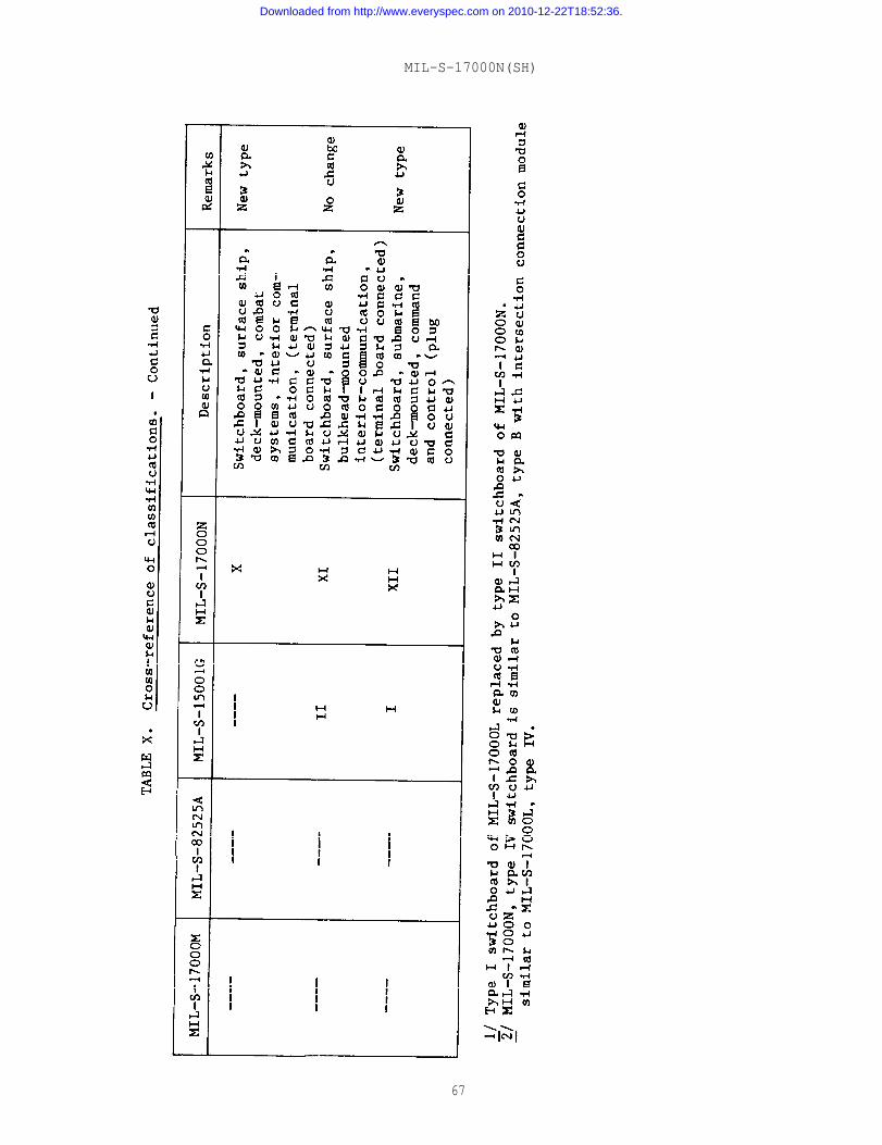
MIL-S-17000N(SH)
67
Downloaded from http://www.everyspec.com on 2010-12-22T18:52:36.
MIL-S-17000N(SH)
6.8 Changes from previous issue. Asterisks are not used in this revisionto identify changes with respect to the previous issue due to the extensiveness
of the changes.
Preparing activity:Navy - SH(Project 1290-N376)
68
Downloaded from http://www.everyspec.com on 2010-12-22T18:52:36.
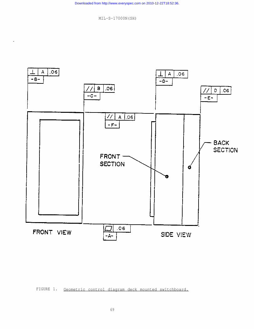
MIL-S-17000N(SH)
FIGURE 1. Geometric control diagram deck mounted switchboard.
69
Downloaded from http://www.everyspec.com on 2010-12-22T18:52:36.
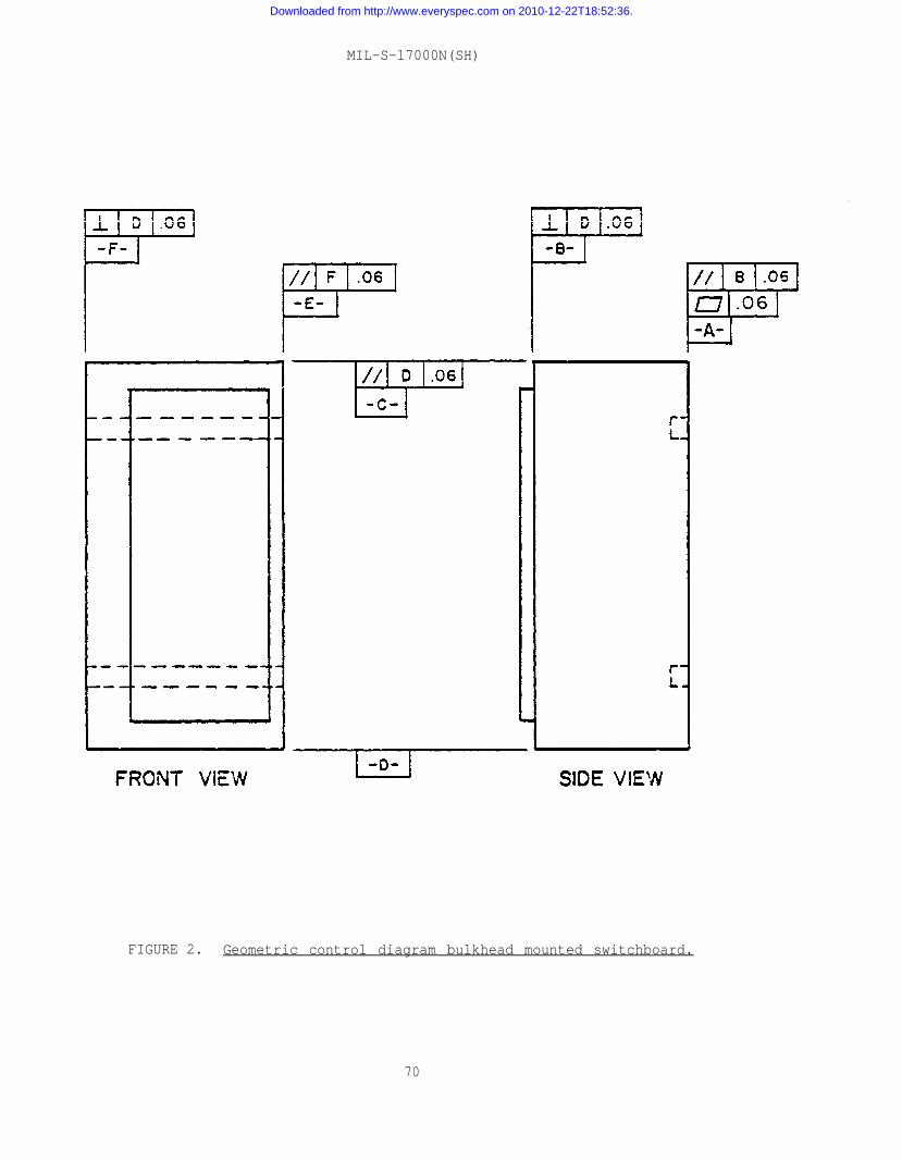
MIL-S-17000N(SH)
FIGURE 2. Geometric control diagram bulkhead mounted switchboard.
70
Downloaded from http://www.everyspec.com on 2010-12-22T18:52:36.
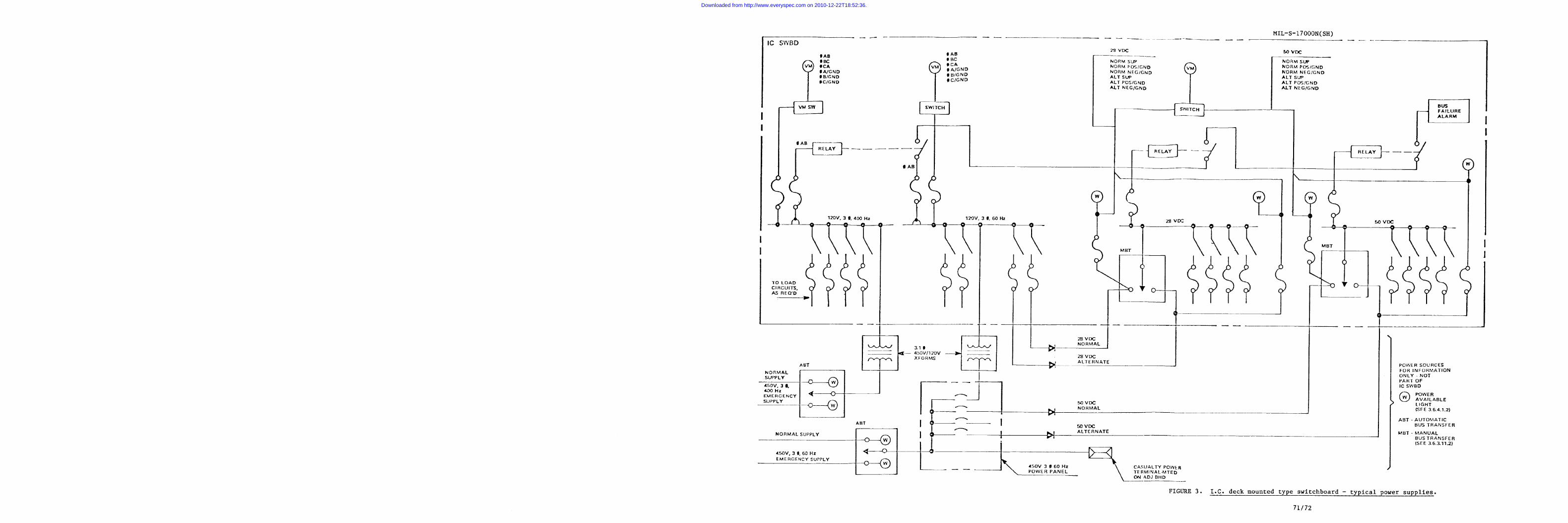
Downloaded from http://www.everyspec.com on 2010-12-22T18:52:36.
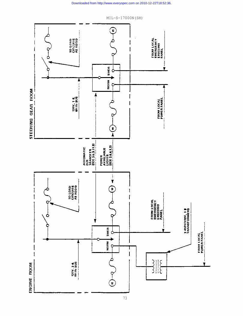
MIL-S-17000N(SH)
73
Downloaded from http://www.everyspec.com on 2010-12-22T18:52:36.
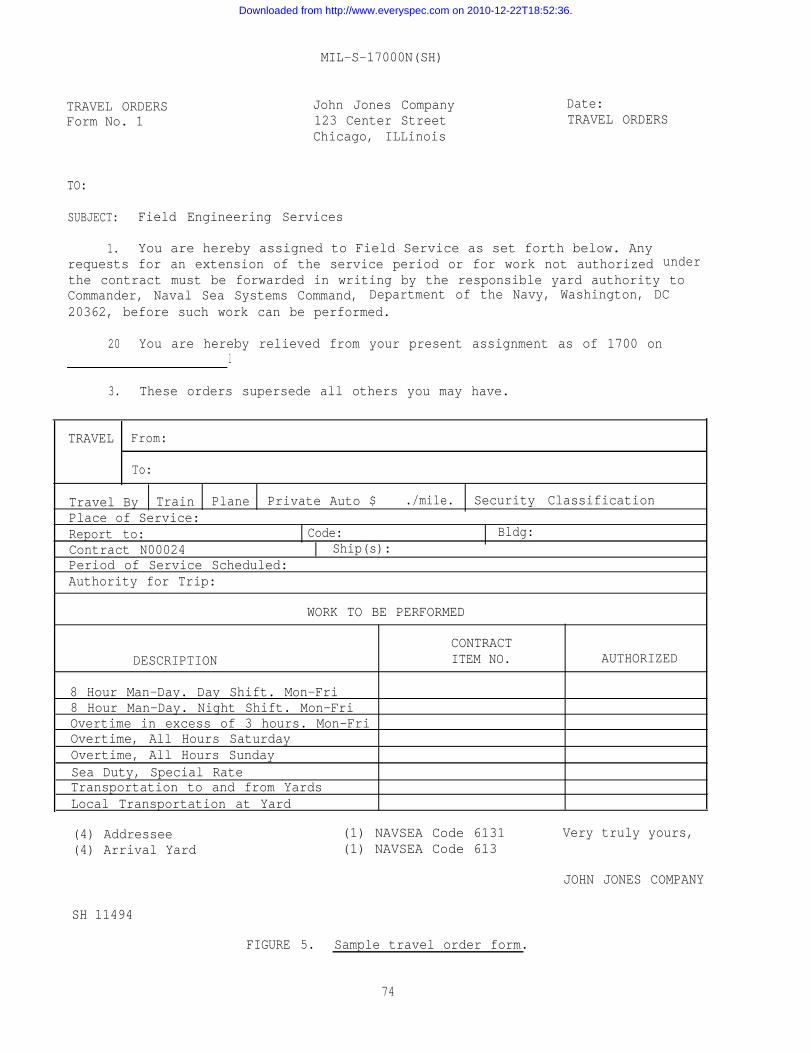
MIL-S-17000N(SH)
TRAVEL ORDERSForm No. 1
John Jones Company123 Center StreetChicago, ILLinois
Date:TRAVEL ORDERS
TO:
SUBJECT: Field Engineering Services
1. You are hereby assigned to Field Service as set forth below. Anyrequests for an extension of the service period or for work not authorized underthe contract must be forwarded in writing by the responsible yard authority toCommander, Naval Sea Systems Command, Department of the Navy, Washington, DC20362, before such work can be performed.
20 You are hereby relieved from your present assignment as of 1700 onl
3. These orders supersede all others you may have.
TRAVEL From:
To:
Travel By Train Plane Private Auto $ ./mile. Security ClassificationPlace of Service:Report to: Code: Bldg:Contract N00024 Ship(s):Period of Service Scheduled:Authority for Trip:
WORK TO BE PERFORMED
CONTRACTDESCRIPTION ITEM NO. AUTHORIZED
8 Hour Man-Day. Day Shift. Mon-Fri8 Hour Man-Day. Night Shift. Mon-FriOvertime in excess of 3 hours. Mon-FriOvertime, All Hours SaturdayOvertime, All Hours SundaySea Duty, Special RateTransportation to and from YardsLocal Transportation at Yard
(4) Addressee (1) NAVSEA Code 6131 Very truly yours,(4) Arrival Yard (1) NAVSEA Code 613
JOHN JONES COMPANY
SH 11494
FIGURE 5. Sample travel order form.
74
Downloaded from http://www.everyspec.com on 2010-12-22T18:52:36.
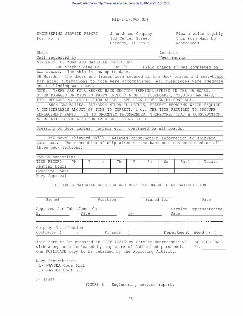
—
MIL-S-17000N(SH)
ENGINEERING SERVICE REPORTForm No. 2
John Jones Company Please write legibly123 Center Street This Form Must beChicago, Illinois Reproduced
Ships LocationCall requested by Week endingSTATEMENT OF WORK AND MATERIAL FURNISHED:
ABC Shipbuilding Co. BB 60: Field Change T7 was completed onall boards. The ship is now up to date.UB Boards: The doors and frames were secured to the deck plates and sway-bracebar after alterations to both were accomplished. All clearances were adequateand no binding was noted.NOTE: THERE ARE FOUR BROKEN BACK SECTION TERMINAL STRIPS IN THE UB BOARD.OTHER DAMAGED OR MISSING PARTS INCLUDE A SPLIT FUSEHOLDER, MISSING HARDWARE,ETC. BECAUSE NO CONSTRUCTION SPACES HAVE BEEN PROVIDED BY CONTRACT.
SUCH CASUALTIES, ALTHOUGH MINOR IN NATURE, PRESENT PROBLEMS WHICH REQUIREA CONSIDERABLE AMOUNT OF TIME TO CORRECT, i.e., THE TIME REQUIRED TO PROCUREREPLACEMENT PARTS. IT IS URGENTLY RECOMMENDED, THEREFORE, THAT A CONSTRUCTIONSPARE KIT BE SUPPLIED FOR EACH SHIP BEING BUILT.
Dressing of door cables, jumpers etc., continued on all boards.
XYZ Naval Shipyard-DD720: Relaved construction information to shipyardpersonnel. The connection of ship wires to the back sections continued on allthree back sections.
NAVSEA Authority:TIME RECORD “M T w Th F Sa Su Shift I TotalsRegular HoursOvertime Hours 1Navy Approval
THE ABOVE MATERIAL RECEIVED AND WORK PERFORMED TO MY SATISFACTION
Signed Position Signed for Date
Approved for John Jones Co. Service RepresentativeBy Date By Date
Company DistributionContracts ( ) Finance ( ) Department Head ( )
This Form to be prepared in TRIPLICATE by Service Representative SERVICE CALLwith acceptance indicated by signature of Authorized personnel. No.One DUPLICATE copy to be retained by the Approving Activity.
Navy Distribution(1) NAVSEA Code 6131(1) NAVSEA Code 613
SH 11495FIGURE 6. Engineering service report.
75
Downloaded from http://www.everyspec.com on 2010-12-22T18:52:36.
MIL-S-17000N(SH)
APPENDIX
SWITCHBOARD, SURFACE SHIP, DECK MOUNTED (TERMINALBOARD - PLUG CONNECTED), QUALIFICATION SAMPLE
10. SCOPE
10.1 Scope. This appendix details the requirements for the constructionof a sample switchboard for submission to qualification tests as specified inthis specification.
20• APPLICABLE DOCUMENTS
20.1 Government documents.
20.1.1 Specifications and standards. Unless otherwise specified, thefollowing specifications and standards of the issue listed in that issue ofthe Department of Defense Indexfied in the solicitation form aherein.
SPECIFICATIONS
MILITARYMIL-S-24187/l -
MIL-C-28748/9 -
MIL-T-55164/13 -
STANDARDS
MILITARYMIL-STD-1657 -
MS3402
MS3409
of Specifications and Standards (DoDISS) speci-part of this appendix to the extent specified
.
Switch Assemblies, Linear Movement, Manual andRemote Operation, Style LS.Connectors, Electrical, Rectangular, Rack andPanel, Polarized Center Jackscrew or GuidepinStyle, Crimp Type Removable Pin Contacts,Size 16.
Terminal Boards, Molded, Barrier, Stud Type,Class 7TB.
Switching Equipment, Combat System, Commandand Control, and Fire Control, Requirements for.
Connectors, Receptacle, Electric, BOX Mounting,Front Release, Crimp Contact, AN Type.
Connectors, Plug Electric, 45 Degree Assembly,Crimp Contacts, AN Type.
(Copies of specifications and standards required by manufacturers in con-nection with specific acquisition functions should be obtained from the con-tracting activity or as directed by the contracting officer.)
76
Downloaded from http://www.everyspec.com on 2010-12-22T18:52:36.
MIL-S-17000N(SH)
300 REQUIREMENTS
30.1 Switchboard section frame. A type II switchboard section frame shallconform to the design shown on the applicable specification sheet (see supple-ment 1), modified as shown on figure 7.
30.2 Modules. Two modules shall be provided and located as shown onfigure 7. The modules shall be as specified in 30.2.1 and 30.2.2.
30.2.1 Module B shall contain one terminal board (type 7TB12) in accord-ance with MIL-T-55164/13 and one module connector receptacle in accordance withMIL-C-28748/9 (part number M28748/09FoNo1A). Weights shall be provided on thismodule to simulate 21 type 7TB12 terminal boards, two harness connectors, andthe associated wiring.
30.2.2 Module D shall contain one MS3402D22-14P box mounted connector,one MS3409D22-14S connector plug, one taper pin block in accordance withrequirement 3 of MIL-sTD-1657, and one module connector receptacle in accord-ance with MIL-C-28748/9 (part number M28748/09FONOlA). Weights shall be providedon this module to simulate four MS3402D40-56P and MS3409D40-56S connectors, 15taper pin blocks, two harness connectors, and the associated wiring.
30.3 Module wiring. Module wiring shall be in accordance with thefollowing:
(a) Wiring from the 7TB12 terminal board to the module connectorreceptacle shall be installed on module B.
(b) Wiring from the 20 circuits of the taper pin block shall beinstalled between the ship and the module connector receptaclesfor module D.
(c) For module D, adequate slack shall be left in the wiring to thetaper pin block from the ship connector and the module connectorso that the front panel of the module will be able to swing downto a 130-degree opening.
30.4 Harness wiring. Flexible harness wiring bundles, containing 312conductors from each module, shall be installed from modules B and D to thepanel mounted assemblies, and interconnected as shown on figure 8.
30.5 Panel-mounted assemblies. Panel-mounted assemblies listed below shallbe provided and located as shown on figure 7. Panel-mounted assemblies shall bein accordance with the applicable requirements of MIL-sTD-1657. These panelassemblies shall be interconnected as shown on figure 8.
(a) One type R3LS4 switch (see 30.7).(b) One indicator light panel. (Requirement 8)(c) One meter panel. (Requirement 10)(d) One relay and fuse panel. (Requirement 6)(e) One switch potential transformer panel. (Requirement 11)(f) One dual switch panel. - This panel shall be similar to the snap
switch panel of requirement 18 of MIL-STD-1657 using one typeS3JK3 switch and one type 1SR2E2 switch.
77
Downloaded from http://www.everyspec.com on 2010-12-22T18:52:36.
MIL-S-17000N(SH)
30.6 Spare panel spaces. The remaining full depth panel spaces in thefront section shall be loaded with weights simulating type RLS remote operatedswitch assemblies. These weights shall be distributed over the full depth ofthe door to accurately simulate the full weight of the switches, the associatedplug connectors, and flexible harness wiring (see figure 7).
30.7 Remote operated switch assembly. The remote operated switch assemblyinstalled in the switchboard shall be in accordance with MIL-S-24187/l.
30.8 Switchboard section shall be assembled in the manufacturers plant.
78
Downloaded from http://www.everyspec.com on 2010-12-22T18:52:36.
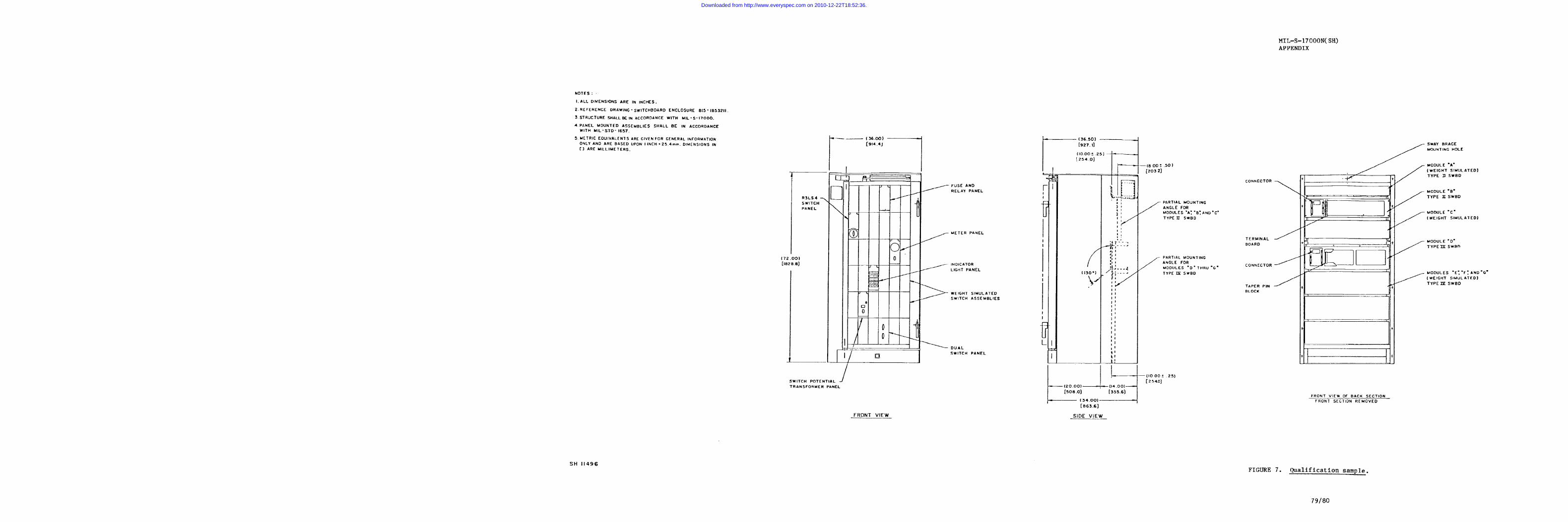
Downloaded from http://www.everyspec.com on 2010-12-22T18:52:36.
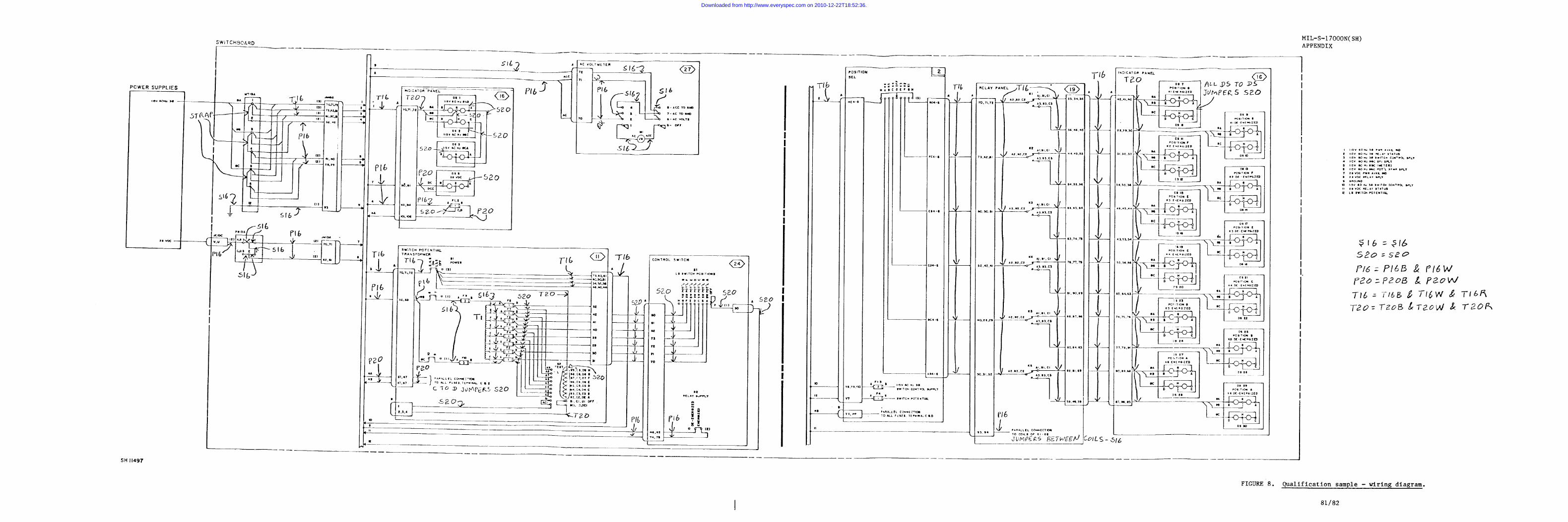
Downloaded from http://www.everyspec.com on 2010-12-22T18:52:36.
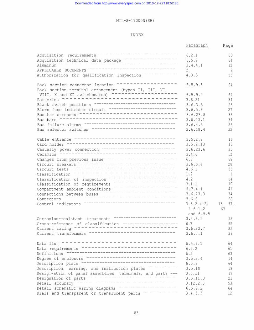
MIL-S-17000N(SH)
INDEX
Acquisition requirements -----------------------
Acquisition technical data package -------------------
Aluminum - - - - - - - - - - - - - - - - - - - - - - -
APPLICABLE DOCUMENTS ----------------------------
Authorization for qualification inspection --------------
Back section connector location ------------------
Back section terminal arrangement (types II, III, VI,VIII, X and XI switchboards) --------------------
Batteries - - - - - - - - - - - - - - - - - - - - - - - - - - - - - -
Blank switch positions ----------------------------------
Blown fuse indicator circuit ----------------------------
Bus bar stresses -----------------------------
Bus bars ------------------------------------
Bus failure alarms --------------------------------------
Bus selector switches ------------------------------
Cable entrance ---------------------------------
Card holder ------------------------------------
Casualty power connection --------------------------------
Ceramics --------------------------------------
Changes from previous issue -------------------------
Circuit breakers -------------------------------------
Circuit tests ------------------------------------
Classification - - - - - - - - - - - - - - - - - - - - - - - - - - -
Classification of inspection ---------------------------
Classification of requirements --------------------------
Compartment ambient conditions ---------------------------
Connections between buses --------------------------------
Connectors ------------------------------------------
Control indicators --------------------------------------
Corrosion-resistant treatments --------------------------
Cross-reference of classification -----------------------Current rating - - - - - - - - - - - - - - - - - - - - - - - - - - - - -
Current transformers ------------------------------
Data list - - - - - - - - - - - - - - - - - - - - - - - - - - - - -
Data requirements -----------------------------
Definitions ------------------------------------------
Degree of enclosure -------------------------------
Description plate ------------------------------------
Description, warning, and instruction plates ------------
Desig.~ation of panel assemblies, terminals, and parts ---Designation of parts ------------------------------------
Detail accuracy -----------------------------------------
Detail schematic wiring diagrams ------------------------
Dials and transparent or translucent parts --------------
Paragraph
6.2.16.5.93.4.4.12.4.3.3
6.5.9.5
6.5.9.43.6.213.6.3.33.6.5.33.6.23.83.6.23.13.6.4.33.6.18.4
3.5.2.93.5.2.133.6.23.63.4.66.83.6.5.44.6.11.24.23.1.13.7.4.13.6.23.33.6.63.5.2.4.2,4.6.1.2and 6.5.5
3.4.9.16.73.6.23.73.6.7.1
6.5.9.16.2.26.53.5.2.46.5.83.5.103.5.113.5.11.33.12.2.36.5.9.23.4.5.3
Page
15,63
6064122
55
64
6434232736342632
161635126828561
541041342857,
13653529
6461631464181921536412
83
Downloaded from http://www.everyspec.com on 2010-12-22T18:52:36.
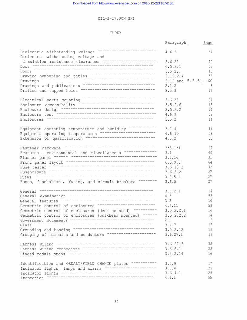
MIL-S-17000N(SH)
INDEX
Paragraph Page
Dielectric withstanding voltage -------------------------
Dielectric withstanding voltage andinsulation resistance clearances -----------------------
Door ----------------------------------------------------
Doors ---------------------------------------------------
Drawing numbering and titles ----------------------------
Drawings ------------------------------------------------
Drawings and publications -------------------------------
Drilled and tapped holes --------------------------------
Electrical parts mounting -------------------------------
Enclosure accessibility ---------------------------------
Enclosure design ----------------------------------------
Enclosure test -------------------------------------------
Enclosures ----------------------------------------------
Equipment operating temperature and humidity ------------
Equipment operating temperatures ------------------------Extension of qualification -----------------------------
Fastener hardware ---------------------------------------
Features - environmental and miscellaneous --------------
Flasher panel ------ -------------------------------------
Front panel layout --------------------------------------
Fuse tester ---------------------------------------------
Fuseholders ---------------------------------------------
Fuses ---------------------------------------------------Fuses, fuseholders, fusing, and circuit breakers --------
General -------------------------------------------------General examination -------------------------------------
General features ----------------------------------------
Geometric control of enclosures -------------------------
Geometric control of enclosures (deck mounted) ----------
Geometric control of enclosures (bulkhead mounted) ------
Government documents ------------------------------------
Glass ---------------------------------------------------
Grounding and bonding -----------------------------------
Grouping of circuits and conductors ---------------------
Harness wiring ------------------------------------------
Harness wiring connectors -------------------------------
Hinged module stops ------------------------------------
Identification and ORDALT/FIELD CHANGE plates -----------
Indicator lights, lamps and alarms ----------------------
Indicator lights ----------------------------------------
Inspection ----------------------------------------------
4.6.3
3.6.296.5.2.13.5.2.73.12.2.43.12 and2.1.23.5.8
3.6.263.5.2.63.5.2.24.6.93.5.2
3.7.44.6.104.3.2
3*5.1*13.73.6.166.5.9.33.6.18.23.6.5.23.6.5.13.6.5
3.5.2.14.53.34.6.113.5.2.2.13.5.2.2.22.13.4.73.5.2.123.6.27.1
3.6.27.33.6.6.13.5.2.14
3.5.93.6.43.6.4.14.4.1
57
40631553
5.3 51, 608
17
3715145814
415855
1440316432272727
1456105814142
121638
382816
17252555
84
Downloaded from http://www.everyspec.com on 2010-12-22T18:52:36.
MIL-S-17000N(SH)
INDEX
Inspection of packaging ----------------------------------
Installation and checkout parts -------------------------
Installation and checkout repair parts ------------------
Insulation resistance test ------------------------------
Intended use --------------------------------------------
Interchangeability - - - - - - - - - - - - - - - - - - - - - - - - -
Interior section illumination ----------------------------
Internal subassembly protection --------------------------
Interpanel wiring --------------------------------------
Intersection wiring -------------------------------------
Laminated materials -------------------------------------
Lamps -----------------------------------------
Level A - - - - - - - - - - - - - - - - - - - - - - - - - - - -
Level C -------------------------------------
Lifting eyebolts - - --------------------------
Linear movement switch connectors ----------------------
Linear movement switches -----------------------------
Magnesium ------------------------------------
Master switches - - - - - - - - - - - - - - - - - - - - - - - - - - - -
Manual operated rotary selector switches -----------------Marking - - - - - - - - - - - - - - - - - - - - - - - - - - - - -
Materials and processes ---------------------------------
Mechanical assembly drawing --------------------------
Mechanical drawings ---------------------------
Mechanical flasher panel --------------------------------Mechanical guidance drawing ------------------------
Metals ------------------------------------
Meter switches -------------------------------Meters -------------------------------------
Molded parts -------------------------------------
Mounting - - --------------------------------
Nonferrous metals ------------------------------------
NOTES -----------------------------------------
Order of precedence -----------------------------------
Ordering data - - - - - - - - - - - - - - - - - - - - - - - - - - - - -
Other publications --------------------------------------
PACKAGING ------------------------------------------
Packaging --------------------------------------
Packing -------------------------------------
Packing of barrel nuts, intersection fastening hardware,and mating ship connector plugs ------------------------
Painting ------------------------------------------
Panel assembly - - - - - - - - - - - - - - - - - - - - - - - - - -Panel assembly number - - - - - - - - - - - - - - - - - - - - - - - -
Paragraph
4.83.95.24.6.46.13.3.33.6.153.5.73.6.27.63.6.27.7
Page
59416058601131173939
3.4.11 133.6.4.2 265.1.1.1and 5.1.2.1 595.1.1.2and 5.1.2.2 59
3.5.2.11 163.6.6.2 283.6.3.14 24
3.4.4.23.6.3.11.13.6.3.95.43.42.12.1.13.12.13.6.16.26.5.9.83.4.43.6.3.133.6.18.13.4.5.13.5.2.5
1224236011515131651224321215
3.4.4.3 126. 60
2.3 106.2 602*2 9
50 595.1.1 595.1.2 59
5.1.3 603.4.8 126.5.4 633.5.11.1 19
85
Downloaded from http://www.everyspec.com on 2010-12-22T18:52:36.
MIL-S-17000N(SH)
INDEX
Paragraph P a g e
Panel-mounted assemblies --------------------------------
Panel-mounted assembly test cables ----------------------
Part identification -------------------------------------
Parts and features - electrical -------------------------
Parts and features - mechanical -------------------------
Parts list (electrical) ---------------------------------
Parts list (parts population) ---------------------------
Phase rotation and polarity -----------------------------
Plastic description plates ------------------------------
Plastics ------------------------------------------------
Potential transformers ----------------------------------
Power available lights ----------------------------------
Power supply tolerances ---------------------------------
Power type rotary switches ------------------------------
Preparation of drawings ---------------------------------
Primary requirements ----------------------------------
Printed wiring board materials ---------------------------
Printed wiring boards -----------------------------------
Prints for submittal ------------------------------------
Protection against corrosion --------------------------
Protection of wiring ------------------------------------
Provisioning --------------------------------------------
Pushbutton assemblies ----------------------------------
Pushbutton switches -------------------------------------
3.5.2.8, 16, 393.6.27.5 52and 3.12.1.3
3.10 453.12.1.5 523.6 213.5 136.5.9.7 653.12.1.6 533.6.23.5 353.4.5.2 123.4.5 123.6.7.2 293.6.4.1.2 263.6.25 373.6.3.11 243.12.2 533.3.1 103.4.10 133.6.30 403.12.2.2 533.4.9 133.5.6 176.6 653.5.14 213.6.3.12 24
Qualification ------------------------------------------- 3.2 10Qualification inspection -------------------------------- 4.3 54Qualification sample ----------------------------------- 4.3.1 55QUALITY ASSURANCE PROVISIONS ---------------------------- 4. 54Quality conformance inspection -------------------------- 4.4 55Quality program ----------------------------------------- 4.1.1 54
Recovered materials -------------------------------------
Relay tester --------------------------------------------
Relays --------------------------------------------------
Remote operated rotary selector switches ----------------
REQUIREMENTS --------------------------------------------
Responsibility for inspection ------------------------
Revision of drawings ------------------------------------
Revision record card ------------------------------------
Rounded corners and edges -------------------------------
3.4.1.1 113.6.18.3 323.6.8 293.6.3.10 243. 104.1 543.12.2.5 533.5.10.4 and 19, 646.5.8.1
3*5*5 17
SCOPE --------------------------------------------------- 1. 1Scope --------------------------------------------------- 1.1 1Selection of metals ------------------------------------- 3.4.9.2 13Sensitive switches -------------------------------------- 3.6.3.8 23Services ------------------------------------------------ 3.11 50
86
Downloaded from http://www.everyspec.com on 2010-12-22T18:52:36.
MIL-S-17000N(SH)
INDEX
Set-up control system --------------------------------
Shielded wiring -----------------------------------------
Ship cable connectors -----------------------------------
Shock ---------------------------------------------------
Shock test ----------------------------------------------
Signal generator ----------------------------------------
Size ----------------------------------------------------
Sockets -------------------------------------------------
Solid state flasher panel -------------------------------
Spare fuse stowage --------------------------------------
Spare panel-mounted assemblies, circuit breakers,or switches ------------------------------------------—
Spare module terminals ----------------------------------
Spare switch poles --------------------------------------
Specification sheets ------------------------------------
Specifications, standards, and handbooks --------------
Springs (material) --------------------------------------
Standard electronic and electrical parts -------------
Standard stock items ------------------------------------
Step plate ----------------------------------------------
Sub-contracted material and parts -----------------------
Subassemblies and mechanical details -----------------
Suppy bus load ------------------------------------------
Supply line voltage and frequency variation -------------
Switch arrangement --------------------------------------
Switch assembly -----------------------------------------
Switch assemblies ---------------------------------------
Switch contact wiring -----------------------------------
Switch mounting -----------------------------------------
Switch, programming -------------------------------------
Switchboard ---------------------------------------------
Switchboard overall assembly drawing - - - - - - - - - - - -
Switchboard section -------------------------------------
Switchboards --------------------------------------------
Switchboards and control indicators -----------------
Switches ------------------------------------------------
Switching and fusing requirements -----------------------
Switching control ---------------------------------------
Switching units, power transfer -------------------------
Synchro capacitors ------------------------------------
Synchro electrical zero and equipmentmechanical zero ----------------------------------------
Synchro signal converter -------------------------------
Synchros ------------------------------------------------
Taper pin blocks ----------------------------------------
Telephone jack box --------------------------------------
Paragraph
6.5.63.6.27.23.6.6.33.7.24.6.73.6.223.5.2.3 and3.12.2.1
3.6.143.6.16.13.6.5.1.1
3.5.43.6.11.33.6.3.43.1201.13.4.4.43.6.23.3.23.5.2.106.43.12.1.43.6.234.6.23.6.3.56.5.33.6.3.13.6.27.43.6.3.26.5.76.5.13.12.1.26.5.21.2.1,3.5.2.4.1,4.6.1.1
5.13.6.33.6.241*2.23.6.3.11.23.6.9.1
3.6.9.23.6.173.6.9
3.6.123.6.19
Page
14,
1,
63382840583453
313127
173023102
122211166252345723632239236363526315,
56
5922372
2429
293229
3132
87
Downloaded from http://www.everyspec.com on 2010-12-22T18:52:36.
MIL-S-17000N(SH)
INDEX
Terminal board mounting -------------------------------—Terminal boards ---------------------------------------
Terminal designation ----------------------------------—
Terminal junction systems -------------------------------
Terminating large conductor ship cables --------------—
Test conditions -----------------------------------------
Test equipment ------------------------------------------Test procedures and test reports ------------------------
Tests ---------------------------------------------------
Through bolting -----------------------------------------Thumbwheel switches -----------------------------------—
Toggle switches -----------------------------------------
Toxic materials ------------------------------------Transformers and inductors ------------------------------
Transient test ---------------------------------------
Type IV, V, and XII switchboards ------------------------
Type VIII switchboards -------------------------------—-
Use of the bus bars --------------------------------
Vibration ------------------------------------------
Vibration test ------------------------------------------
Wire -------------------------------------------------
Wire markers --------------------------------------------
Wire marking ------------------------------------------Wire pullout tests -------------------------------------
Wire size ---------------------------------------------
Wire terminal lugs -------------------------------------Wire type ---------------------------------------------
Wiring --------------------------------------------------Wiring details --------------------------------------Wiring fixtures -----------------------------------------
Wiring space ------------------------------------------
Wood ----------------------------------------------------
Workmanship ------------------------------------------
Zinc - - - - - - - - - - - - - - - - - - - - - - - - - - - - - - - - - - - - -
Figure 1 -Figure 2 -Figure 3 -Figure 4 -Figure 5 -Figure 6 -Figure 7 -Figure 8 -
FIGURES
Paragraph
3.6.11.23.6.113.5.11.23.6.133.6.11.44.4.23.6.184.74.63.5.33.6.3.63.6.3.73.4.23.6.74.6.86.5.9.5.16.5.9.5.2
3.6.23.2
3.7.34.6.6
3.6.203.5.133.5.124.6.53.6.20.23.6.103.6.20.13.6.27 6.5.9.63.83.6.283.4.33.13
3.4.4.3.1
Geometric control diagram deck mounted switchboard -----------
Geometric control diagram bulkhead mounted switchboard -------
I.C. deck mounted type switchboard - typical power supplies --I.C. bulkhead local I.C. switchboards ------------------------
Sample travel order form -------------------------------------Engineering service report -----------------------------------
Qualification sample -----------------------------------------
Qualification sample - wiring diagram ------------------------
Page
3030193130563259561723231128586465
34
4058
32212158332932376541391154
12
697071/7273747579/8081/82
88
Downloaded from http://www.everyspec.com on 2010-12-22T18:52:36.
TableTableTableTableTableTableTableTableTableTable
MIL-S-17000N(SH)
INDEX
TABLES
I - Terminal designation ------------------------------------
II - Lamps -------------------------------------------III - Circuit load, fuse rating, and wire size data -------------
IV - Ampere rating of rectangular bus bars placed on edge ------
V - Installation and checkout repair parts --------------------VI - List of required tools in support of switchboard ----------
VII - Qualification inspection ----------------------------------
VIII - Quality conformance inspection ----------------------------xx - Dielectric withstanding voltages --------------------------
x - Cross-reference of classifications ------------------------
APPENDIX
Appendix - Switchboard, Surface Ship, Deck Mounted (Terminal Board -Plug Connected), Qualification Sample --------------------
U.S. GOVERNMENT PRINTING OFFICE: 1983-605-034/2564
89
Page
19253335414655555766
76
Downloaded from http://www.everyspec.com on 2010-12-22T18:52:36.

Downloaded from http://www.everyspec.com on 2010-12-22T18:52:36.
Downloaded from http://www.everyspec.com on 2010-12-22T18:52:36.
Downloaded from http://www.everyspec.com on 2010-12-22T18:52:36.


![IINCH-POUND ] MIL-S-24235/16B (SH) 28 December 1992 …everyspec.com/MIL-SPECS/MIL-SPECS-MIL-S/download.php?... · iinch-pound ] mil-s-24235/16b (sh) 28 december 1992 superseding](https://static.fdocuments.us/doc/165x107/614879662918e2056c22b67c/iinch-pound-mil-s-2423516b-sh-28-december-1992-iinch-pound-mil-s-2423516b.jpg)