Mikoyan & Gurevich MiG 15UTI, VH-LSN Canberra, ACT 13 ... · INVESTIGATION REPORT 9300484 Mikoyan &...
30
Department of Transport and Regional Development Bureau of Air Safety Investigation INVESTIGATION REPORT 9300484 Mikoyan & Gurevich MiG 15UTI, VH-LSN Canberra, ACT 13 March 1993 Released by the Secretary of the Department of Transport and Regional Development under the provisions of Section 19CU of part 2A of the Air Navigation Act (1920).
Transcript of Mikoyan & Gurevich MiG 15UTI, VH-LSN Canberra, ACT 13 ... · INVESTIGATION REPORT 9300484 Mikoyan &...

Department of Transport and Regional Development
Bureau of Air Safety Investigation
INVESTIGATION REPORT
9300484
Mikoyan & GurevichMiG 15UTI, VH-LSNCanberra, ACT13 March 1993
Released by the Secretary of the Department of Transport and Regional Development
under the provisions of Section 19CU of part 2A of the Air Navigation Act (1920).

ii
ISBN 0 642 25624 1 September 1996
When the Bureau makes recommendations as a result of itsinvestigations or research, safety, (in accordance with itscharter), is its primary consideration. However, the Bureaufully recognises that the implementation of recommendationsarising from its investigations will in some cases incur a costto the industry.
Readers should note that the information in BASI reports isprovided to promote aviation safety: in no case is it intendedto imply blame or liability.
This report was produced by the Bureau of Air Safety Investigation (BASI), PO Box 967, Civic Square ACT 2608.
Readers are advised that the Bureau investigates for the sole purpose of enhancing aviation safety. Consequently,Bureau reports are confined to matters of safety significance and may be misleading if used for any other purpose.
As BASI believes that safety information is of greatest value if it is passed on for the use of others, readers areencouraged to copy or reprint for further distribution, acknowledging BASI as the source.

iii
FOREWORD
Having received additional factual information at the coronial inquest (Canberra,July 1995) into the deaths of the pilot and passenger of VH-LSN, and followingrepresentation by interested parties, the Bureau of Air Safety Investigation re-openedthe investigation of this accident. As a result, the original investigation report(published July 1994) is withdrawn and is superseded by this present report.

iv

v
CONTENTS
Glossary of terms and abbreviations ... . . . . . . . . . . . . . . . . . . . . . . . . . . . . . . . . . . . . . . . . . . . . . . . . . . . . . . . . . . . . . . . . . . . . . . . . . . . . . . . . . . . . . . . . . . . . . . . . . . . . . . . . . . . . . . . . . . . . . . . . . . . . . . . . . . . . . . . . . . . . . . . . . . . . . . . . . . . . . . . . . . . . vii
Approximate flight path and impact location of VH-LSN ... . . . . . . . . . . . . . . . . . . . . . . . . . . . . . . . . . . . . . . . . . . . . . . . . . . . . . . . . . . . . . . . . . . . . . . . . . . . . . . . . . . . . . . . . . . . . . . . viii
SYNOPSIS ... . . . . . . . . . . . . . . . . . . . . . . . . . . . . . . . . . . . . . . . . . . . . . . . . . . . . . . . . . . . . . . . . . . . . . . . . . . . . . . . . . . . . . . . . . . . . . . . . . . . . . . . . . . . . . . . . . . . . . . . . . . . . . . . . . . . . . . . . . . . . . . . . . . . . . . . . . . . . . . . . . . . . . . . . . . . . . . . . . . . . . . . . . . . . . . . . . . . . . . . . . . . . . . . . . . . . . . . . . . . . . . . . . . . . . . . . . . . . . . . . . . . . . . . . 1
1. FACTUAL INFORMATION .... . . . . . . . . . . . . . . . . . . . . . . . . . . . . . . . . . . . . . . . . . . . . . . . . . . . . . . . . . . . . . . . . . . . . . . . . . . . . . . . . . . . . . . . . . . . . . . . . . . . . . . . . . . . . . . . . . . . . . . . . . . . . . . . . . . . . . . . . . . . . . . . . . . . . . . . . . . . . . . . . . . . . . . . . . . 1
1.1 History of the flight ... . . . . . . . . . . . . . . . . . . . . . . . . . . . . . . . . . . . . . . . . . . . . . . . . . . . . . . . . . . . . . . . . . . . . . . . . . . . . . . . . . . . . . . . . . . . . . . . . . . . . . . . . . . . . . . . . . . . . . . . . . . . . . . . . . . . . . . . . . . . . . . . . . . . . . . . . . . . . . . . . . . . . . . . . . . . . . 1
1.2 Injuries to persons ... . . . . . . . . . . . . . . . . . . . . . . . . . . . . . . . . . . . . . . . . . . . . . . . . . . . . . . . . . . . . . . . . . . . . . . . . . . . . . . . . . . . . . . . . . . . . . . . . . . . . . . . . . . . . . . . . . . . . . . . . . . . . . . . . . . . . . . . . . . . . . . . . . . . . . . . . . . . . . . . . . . . . . . . . . . . . . . . . . 2
1.3 Damage to aircraft ... . . . . . . . . . . . . . . . . . . . . . . . . . . . . . . . . . . . . . . . . . . . . . . . . . . . . . . . . . . . . . . . . . . . . . . . . . . . . . . . . . . . . . . . . . . . . . . . . . . . . . . . . . . . . . . . . . . . . . . . . . . . . . . . . . . . . . . . . . . . . . . . . . . . . . . . . . . . . . . . . . . . . . . . . . . . . . . . . . 2
1.4 Other damage ... . . . . . . . . . . . . . . . . . . . . . . . . . . . . . . . . . . . . . . . . . . . . . . . . . . . . . . . . . . . . . . . . . . . . . . . . . . . . . . . . . . . . . . . . . . . . . . . . . . . . . . . . . . . . . . . . . . . . . . . . . . . . . . . . . . . . . . . . . . . . . . . . . . . . . . . . . . . . . . . . . . . . . . . . . . . . . . . . . . . . . . . . . . . . . . . . 2
1.5 Personnel information ... . . . . . . . . . . . . . . . . . . . . . . . . . . . . . . . . . . . . . . . . . . . . . . . . . . . . . . . . . . . . . . . . . . . . . . . . . . . . . . . . . . . . . . . . . . . . . . . . . . . . . . . . . . . . . . . . . . . . . . . . . . . . . . . . . . . . . . . . . . . . . . . . . . . . . . . . . . . . . . . . . . . . . 2
1.5.1 Pilot MiG 15UTI experience ... . . . . . . . . . . . . . . . . . . . . . . . . . . . . . . . . . . . . . . . . . . . . . . . . . . . . . . . . . . . . . . . . . . . . . . . . . . . . . . . . . . . . . . . . . . . . . . . . . . . . . . . . . . . . . . . . . . . . . . . . . . 3
1.6 Aircraft information ... . . . . . . . . . . . . . . . . . . . . . . . . . . . . . . . . . . . . . . . . . . . . . . . . . . . . . . . . . . . . . . . . . . . . . . . . . . . . . . . . . . . . . . . . . . . . . . . . . . . . . . . . . . . . . . . . . . . . . . . . . . . . . . . . . . . . . . . . . . . . . . . . . . . . . . . . . . . . . . . . . . . . . . . . . . . 3
1.6.1 Aircraft .. . . . . . . . . . . . . . . . . . . . . . . . . . . . . . . . . . . . . . . . . . . . . . . . . . . . . . . . . . . . . . . . . . . . . . . . . . . . . . . . . . . . . . . . . . . . . . . . . . . . . . . . . . . . . . . . . . . . . . . . . . . . . . . . . . . . . . . . . . . . . . . . . . . . . . . . . . . . . . . . . . . . . . . . . . . . . . . . . . . . . . . . . . . . . . . . 3
1.6.2 Engine ... . . . . . . . . . . . . . . . . . . . . . . . . . . . . . . . . . . . . . . . . . . . . . . . . . . . . . . . . . . . . . . . . . . . . . . . . . . . . . . . . . . . . . . . . . . . . . . . . . . . . . . . . . . . . . . . . . . . . . . . . . . . . . . . . . . . . . . . . . . . . . . . . . . . . . . . . . . . . . . . . . . . . . . . . . . . . . . . . . . . . . . . . . . . . . . . . . 4
1.7 Meteorological information ... . . . . . . . . . . . . . . . . . . . . . . . . . . . . . . . . . . . . . . . . . . . . . . . . . . . . . . . . . . . . . . . . . . . . . . . . . . . . . . . . . . . . . . . . . . . . . . . . . . . . . . . . . . . . . . . . . . . . . . . . . . . . . . . . . . . . . . . . . . . . . . . . . . . . 4
1.8 Aids to navigation ... . . . . . . . . . . . . . . . . . . . . . . . . . . . . . . . . . . . . . . . . . . . . . . . . . . . . . . . . . . . . . . . . . . . . . . . . . . . . . . . . . . . . . . . . . . . . . . . . . . . . . . . . . . . . . . . . . . . . . . . . . . . . . . . . . . . . . . . . . . . . . . . . . . . . . . . . . . . . . . . . . . . . . . . . . . . . . . . . . . 4
1.9 Communications ... . . . . . . . . . . . . . . . . . . . . . . . . . . . . . . . . . . . . . . . . . . . . . . . . . . . . . . . . . . . . . . . . . . . . . . . . . . . . . . . . . . . . . . . . . . . . . . . . . . . . . . . . . . . . . . . . . . . . . . . . . . . . . . . . . . . . . . . . . . . . . . . . . . . . . . . . . . . . . . . . . . . . . . . . . . . . . . . . . . . . . . 4
1.10 Aerodrome information ... . . . . . . . . . . . . . . . . . . . . . . . . . . . . . . . . . . . . . . . . . . . . . . . . . . . . . . . . . . . . . . . . . . . . . . . . . . . . . . . . . . . . . . . . . . . . . . . . . . . . . . . . . . . . . . . . . . . . . . . . . . . . . . . . . . . . . . . . . . . . . . . . . . . . . . . . . . . . . . . 4
1.11 Flight recorders .. . . . . . . . . . . . . . . . . . . . . . . . . . . . . . . . . . . . . . . . . . . . . . . . . . . . . . . . . . . . . . . . . . . . . . . . . . . . . . . . . . . . . . . . . . . . . . . . . . . . . . . . . . . . . . . . . . . . . . . . . . . . . . . . . . . . . . . . . . . . . . . . . . . . . . . . . . . . . . . . . . . . . . . . . . . . . . . . . . . . . . . . . . . . . 5
1.12 Wreckage and impact information ... . . . . . . . . . . . . . . . . . . . . . . . . . . . . . . . . . . . . . . . . . . . . . . . . . . . . . . . . . . . . . . . . . . . . . . . . . . . . . . . . . . . . . . . . . . . . . . . . . . . . . . . . . . . . . . . . . . . . . . . . . . . . . 5
1.12.1 Engine examination ... . . . . . . . . . . . . . . . . . . . . . . . . . . . . . . . . . . . . . . . . . . . . . . . . . . . . . . . . . . . . . . . . . . . . . . . . . . . . . . . . . . . . . . . . . . . . . . . . . . . . . . . . . . . . . . . . . . . . . . . . . . . . . . . . . . . . . . . . . . . . . . 6
1.12.2 Barometric pressure controller .. . . . . . . . . . . . . . . . . . . . . . . . . . . . . . . . . . . . . . . . . . . . . . . . . . . . . . . . . . . . . . . . . . . . . . . . . . . . . . . . . . . . . . . . . . . . . . . . . . . . . . . . . . . . . 7
1.12.3 Throttle valve ... . . . . . . . . . . . . . . . . . . . . . . . . . . . . . . . . . . . . . . . . . . . . . . . . . . . . . . . . . . . . . . . . . . . . . . . . . . . . . . . . . . . . . . . . . . . . . . . . . . . . . . . . . . . . . . . . . . . . . . . . . . . . . . . . . . . . . . . . . . . . . . . . . . . . . . . . . . . . . . . . . . 7
1.12.4 Engine lower high pressure fuel pump ... . . . . . . . . . . . . . . . . . . . . . . . . . . . . . . . . . . . . . . . . . . . . . . . . . . . . . . . . . . . . . . . . . . . . . . . . . . . . . . . . . . 7
1.12.5 Engine upper high pressure fuel pump ... . . . . . . . . . . . . . . . . . . . . . . . . . . . . . . . . . . . . . . . . . . . . . . . . . . . . . . . . . . . . . . . . . . . . . . . . . . . . . . . . 7
1.12.6 Number three rear fuel tank ... . . . . . . . . . . . . . . . . . . . . . . . . . . . . . . . . . . . . . . . . . . . . . . . . . . . . . . . . . . . . . . . . . . . . . . . . . . . . . . . . . . . . . . . . . . . . . . . . . . . . . . . . . . . . . . . . . . . 7
1.12.7 Number three tank boost pump ... . . . . . . . . . . . . . . . . . . . . . . . . . . . . . . . . . . . . . . . . . . . . . . . . . . . . . . . . . . . . . . . . . . . . . . . . . . . . . . . . . . . . . . . . . . . . . . . . . . . . . . 7
1.12.8 Rudder and elevator control push-pull tubes ... . . . . . . . . . . . . . . . . . . . . . . . . . . . . . . . . . . . . . . . . . . . . . . . . . . . . . . . . . . . . . 8
1.12.9 Fire extinguishing system ... . . . . . . . . . . . . . . . . . . . . . . . . . . . . . . . . . . . . . . . . . . . . . . . . . . . . . . . . . . . . . . . . . . . . . . . . . . . . . . . . . . . . . . . . . . . . . . . . . . . . . . . . . . . . . . . . . . . . . . . . . . . . 9
1.13 Medical and pathological information ... . . . . . . . . . . . . . . . . . . . . . . . . . . . . . . . . . . . . . . . . . . . . . . . . . . . . . . . . . . . . . . . . . . . . . . . . . . . . . . . . . . . . . . . . . . . . . . . . . . . . . . . . . . . . . . . . . 9
1.14 Fire ... . . . . . . . . . . . . . . . . . . . . . . . . . . . . . . . . . . . . . . . . . . . . . . . . . . . . . . . . . . . . . . . . . . . . . . . . . . . . . . . . . . . . . . . . . . . . . . . . . . . . . . . . . . . . . . . . . . . . . . . . . . . . . . . . . . . . . . . . . . . . . . . . . . . . . . . . . . . . . . . . . . . . . . . . . . . . . . . . . . . . . . . . . . . . . . . . . . . . . . . . . . . . . . . . . . . . . . . . . . . . . . . . . . 9
1.15 Survival aspects .. . . . . . . . . . . . . . . . . . . . . . . . . . . . . . . . . . . . . . . . . . . . . . . . . . . . . . . . . . . . . . . . . . . . . . . . . . . . . . . . . . . . . . . . . . . . . . . . . . . . . . . . . . . . . . . . . . . . . . . . . . . . . . . . . . . . . . . . . . . . . . . . . . . . . . . . . . . . . . . . . . . . . . . . . . . . . . . . . . . . . . . . . . 10
1.16 Prior event ... . . . . . . . . . . . . . . . . . . . . . . . . . . . . . . . . . . . . . . . . . . . . . . . . . . . . . . . . . . . . . . . . . . . . . . . . . . . . . . . . . . . . . . . . . . . . . . . . . . . . . . . . . . . . . . . . . . . . . . . . . . . . . . . . . . . . . . . . . . . . . . . . . . . . . . . . . . . . . . . . . . . . . . . . . . . . . . . . . . . . . . . . . . . . . . . . . . . . . . . 11
1.17 Fuselage fire detection system ... . . . . . . . . . . . . . . . . . . . . . . . . . . . . . . . . . . . . . . . . . . . . . . . . . . . . . . . . . . . . . . . . . . . . . . . . . . . . . . . . . . . . . . . . . . . . . . . . . . . . . . . . . . . . . . . . . . . . . . . . . . . . . . . . . . . . . . . . . . 11
1.18 Aircraft documentation ... . . . . . . . . . . . . . . . . . . . . . . . . . . . . . . . . . . . . . . . . . . . . . . . . . . . . . . . . . . . . . . . . . . . . . . . . . . . . . . . . . . . . . . . . . . . . . . . . . . . . . . . . . . . . . . . . . . . . . . . . . . . . . . . . . . . . . . . . . . . . . . . . . . . . . . . . . . . . . . 11
1.19 Permit to fly ... . . . . . . . . . . . . . . . . . . . . . . . . . . . . . . . . . . . . . . . . . . . . . . . . . . . . . . . . . . . . . . . . . . . . . . . . . . . . . . . . . . . . . . . . . . . . . . . . . . . . . . . . . . . . . . . . . . . . . . . . . . . . . . . . . . . . . . . . . . . . . . . . . . . . . . . . . . . . . . . . . . . . . . . . . . . . . . . . . . . . . . . . . . . . . . . . . . 12
1.20 Aircraft test flight .. . . . . . . . . . . . . . . . . . . . . . . . . . . . . . . . . . . . . . . . . . . . . . . . . . . . . . . . . . . . . . . . . . . . . . . . . . . . . . . . . . . . . . . . . . . . . . . . . . . . . . . . . . . . . . . . . . . . . . . . . . . . . . . . . . . . . . . . . . . . . . . . . . . . . . . . . . . . . . . . . . . . . . . . . . . . . . . . . . . 12
1.21 CAA endorsement requirements .. . . . . . . . . . . . . . . . . . . . . . . . . . . . . . . . . . . . . . . . . . . . . . . . . . . . . . . . . . . . . . . . . . . . . . . . . . . . . . . . . . . . . . . . . . . . . . . . . . . . . . . . . . . . . . . . . . . . . . . . . . . . . . . . . . . 12
1.22 CAA documents ... . . . . . . . . . . . . . . . . . . . . . . . . . . . . . . . . . . . . . . . . . . . . . . . . . . . . . . . . . . . . . . . . . . . . . . . . . . . . . . . . . . . . . . . . . . . . . . . . . . . . . . . . . . . . . . . . . . . . . . . . . . . . . . . . . . . . . . . . . . . . . . . . . . . . . . . . . . . . . . . . . . . . . . . . . . . . . . . . . . . . . 13
1.23 Video tape ... . . . . . . . . . . . . . . . . . . . . . . . . . . . . . . . . . . . . . . . . . . . . . . . . . . . . . . . . . . . . . . . . . . . . . . . . . . . . . . . . . . . . . . . . . . . . . . . . . . . . . . . . . . . . . . . . . . . . . . . . . . . . . . . . . . . . . . . . . . . . . . . . . . . . . . . . . . . . . . . . . . . . . . . . . . . . . . . . . . . . . . . . . . . . . . . . . . . . . . . . 13
2. ANALYSIS ... . . . . . . . . . . . . . . . . . . . . . . . . . . . . . . . . . . . . . . . . . . . . . . . . . . . . . . . . . . . . . . . . . . . . . . . . . . . . . . . . . . . . . . . . . . . . . . . . . . . . . . . . . . . . . . . . . . . . . . . . . . . . . . . . . . . . . . . . . . . . . . . . . . . . . . . . . . . . . . . . . . . . . . . . . . . . . . . . . . . . . . . . . . . . . . . . . . . . . . . . . . . . . . . . . . . . . . . . . . . . . . . . . 15
2.1 Introduction ... . . . . . . . . . . . . . . . . . . . . . . . . . . . . . . . . . . . . . . . . . . . . . . . . . . . . . . . . . . . . . . . . . . . . . . . . . . . . . . . . . . . . . . . . . . . . . . . . . . . . . . . . . . . . . . . . . . . . . . . . . . . . . . . . . . . . . . . . . . . . . . . . . . . . . . . . . . . . . . . . . . . . . . . . . . . . . . . . . . . . . . . . . . . . . . . . . . 15
2.2 In-flight fuselage fire ... . . . . . . . . . . . . . . . . . . . . . . . . . . . . . . . . . . . . . . . . . . . . . . . . . . . . . . . . . . . . . . . . . . . . . . . . . . . . . . . . . . . . . . . . . . . . . . . . . . . . . . . . . . . . . . . . . . . . . . . . . . . . . . . . . . . . . . . . . . . . . . . . . . . . . . . . . . . . . . . . . . . . . . . 15
2.3 Turbine blade failures .. . . . . . . . . . . . . . . . . . . . . . . . . . . . . . . . . . . . . . . . . . . . . . . . . . . . . . . . . . . . . . . . . . . . . . . . . . . . . . . . . . . . . . . . . . . . . . . . . . . . . . . . . . . . . . . . . . . . . . . . . . . . . . . . . . . . . . . . . . . . . . . . . . . . . . . . . . . . . . . . . . . . . . 16

2.4 Airframe and aircraft component documentation ... . . . . . . . . . . . . . . . . . . . . . . . . . . . . . . . . . . . . . . . . . . . . . . . . . . . . . . . . . . . . . . . . . . . . . . . . . . . . 17
2.5 Flight crew qualifications for the operation of ex-military aircraft .. . . . . . . . . . . . . . . . . . . . . . . . . . 17
2.6 Ex-military aircraft operations ... . . . . . . . . . . . . . . . . . . . . . . . . . . . . . . . . . . . . . . . . . . . . . . . . . . . . . . . . . . . . . . . . . . . . . . . . . . . . . . . . . . . . . . . . . . . . . . . . . . . . . . . . . . . . . . . . . . . . . . . . . . . . . . . . . . . . . . . . . . 17
3. CONCLUSIONS .... . . . . . . . . . . . . . . . . . . . . . . . . . . . . . . . . . . . . . . . . . . . . . . . . . . . . . . . . . . . . . . . . . . . . . . . . . . . . . . . . . . . . . . . . . . . . . . . . . . . . . . . . . . . . . . . . . . . . . . . . . . . . . . . . . . . . . . . . . . . . . . . . . . . . . . . . . . . . . . . . . . . . . . . . . . . . . . . . . . . . . . . . . . . . . . . . . . . . . . . . . . . . . . 19
3.1 Findings ... . . . . . . . . . . . . . . . . . . . . . . . . . . . . . . . . . . . . . . . . . . . . . . . . . . . . . . . . . . . . . . . . . . . . . . . . . . . . . . . . . . . . . . . . . . . . . . . . . . . . . . . . . . . . . . . . . . . . . . . . . . . . . . . . . . . . . . . . . . . . . . . . . . . . . . . . . . . . . . . . . . . . . . . . . . . . . . . . . . . . . . . . . . . . . . . . . . . . . . . . . . . . . . . . . . 19
3.2 Significant factors .. . . . . . . . . . . . . . . . . . . . . . . . . . . . . . . . . . . . . . . . . . . . . . . . . . . . . . . . . . . . . . . . . . . . . . . . . . . . . . . . . . . . . . . . . . . . . . . . . . . . . . . . . . . . . . . . . . . . . . . . . . . . . . . . . . . . . . . . . . . . . . . . . . . . . . . . . . . . . . . . . . . . . . . . . . . . . . . . . . . . . . 19
4. SAFETY ACTION ... . . . . . . . . . . . . . . . . . . . . . . . . . . . . . . . . . . . . . . . . . . . . . . . . . . . . . . . . . . . . . . . . . . . . . . . . . . . . . . . . . . . . . . . . . . . . . . . . . . . . . . . . . . . . . . . . . . . . . . . . . . . . . . . . . . . . . . . . . . . . . . . . . . . . . . . . . . . . . . . . . . . . . . . . . . . . . . . . . . . . . . . . . . . . . . . . . . . . . . . . . . . 20
4.1 Safety action taken ... . . . . . . . . . . . . . . . . . . . . . . . . . . . . . . . . . . . . . . . . . . . . . . . . . . . . . . . . . . . . . . . . . . . . . . . . . . . . . . . . . . . . . . . . . . . . . . . . . . . . . . . . . . . . . . . . . . . . . . . . . . . . . . . . . . . . . . . . . . . . . . . . . . . . . . . . . . . . . . . . . . . . . . . . . . . . . . . . . 20
vi

vii
GLOSSARY OF TERMS AND ABBREVIATIONS
AGL above ground level
AMSL above mean sea level
ATC air traffic control
ATIS Automatic Terminal Information Service
ATPL Airline Transport Pilot Licence
AWI Airworthiness Instructions
BPC barometric pressure controller
CAA Civil Aviation Authority
CAO Civil Aviation Orders
CAR Civil Aviation Regulations
cm centimetres
EST Eastern Standard Time
FOI Flying Operations Instructions
HP high pressure
IAS indicated airspeed
ICAO International Civil Aviation Organisation
j.p.t. jet pipe temperature
NGV nozzle guide vane(s)
NSW New South Wales
psi pounds per square inch
RPM revolutions per minute
RFFS rescue fire fighting service
SEM Scanning Electron Microscope
SN Serial Number
TSI time since last inspection
TTIS total time in service
°C degrees Celsius
Blade creep Plastic deformation of a blade under prolonged load, greatly accelerated byhigh temperatures.
QNH The altimeter sub-scale setting in hectopascals which when set on thealtimeter, provides the pilot a reference in height as related to mean sea level.
All times are Eastern Standard Time (Co-ordinated Universal Time plus 10 hours) unlessspecifically stated.

viii
WODEN VALLEY
SOUTH CANBERRA
FYSHWICK
QUEANBEYAN
NORTH CANBERRA
LakeBurley
Griffin Canberra Airport
Jerrabomberra Hill779 m
Mt Ainslie 843 m
Mt Majura 888 m
NARRABUNDAH
Black Mountain 812 m
Red Hill 720 m
Hindmarsh D rive
Canberra Avenue
CRASH SITE
Monaro H
ighway
Figure 1. Approximate flight path and impact location of VH-LSN

1
1. FACTUAL INFORMATION
1.1 History of the flight
On 13 March 1993, the MiG 15UTI VH-LSN with the pilot and one passenger on board tookoff from Canberra Airport for a city sight-seeing tour and a flight to one of the local trainingareas. Prior to receiving taxi clearance, the pilot was given ATIS information and was clearedfor a standard city route at 4,000 ft. The aircraft then taxied for runway 12 at 1605:30 EST.
After receiving a take-off clearance, the aircraft was observed to enter runway 12 andcommence the take-off roll. No abnormalities were observed by eye witnesses. After becomingairborne, the aircraft levelled briefly at about 15 ft AGL and the landing gear was retracted. Theaircraft then entered a left climbing turn and levelled again at about 1,200 ft AGL.
At 1611:25 the pilot reported that he was downwind for runway 12 and requested a clearanceto land due to a minor unserviceability. The pilot then reported that he was at 3,000 ft AMSLand requested minimum delay. He was advised of a B737 on left base for runway 35 and wasasked to report sighting the aircraft. At 1612:25 the pilot stated that he would take runway 12and when he was advised by the aerodrome controller that he would be number two, he statedthat he had the B737 in sight and that he would land on runway 35. At 1613:55 the pilotrequested a wind check. No further transmissions from the pilot were recorded. During thelatter part of the flight the aircraft was in a shallow descent and had descended to about 500 ftAGL when it was observed to enter a nose-down attitude of about 30°.
A diagram depicting the approximate flight path and impact location of VH-LSN is at figure 1.
Shortly afterwards a fire and smoke plume were observed by tower personnel and the crashalarm was activated. Two units of the Canberra Airport rescue fire fighting service weredispatched to the scene.
Impact occurred about 2 minutes and 30 seconds after the pilot advised that he had a problem.
SYNOPSIS
The MiG 15UTI, VH-LSN, took off from runway 12 at Canberra Airport with thepilot and one passenger on board. After becoming airborne, the aircraft entered aclimbing left turn and levelled at about 1,200 ft above ground level. The pilotadvised the tower controller that he was having a minor technical problem andrequested a landing. After a short discussion, the aircraft was cleared to land onrunway 35. When the aircraft was about 4 km from the threshold of runway 35, itwas seen to enter a steep nose-down attitude. The aircraft subsequentlyimpacted the ground and the pilot and passenger were killed.
The Bureau of Air Safety Investigation’s analysis determined that an in-flight fire,fuelled by an unknown source of combustible material, melted and burned therudder and elevator control tubes located in the fuselage aft of frame 21. As aresult of the damage to these items, control of the aircraft was lost. The areawhere the fire occurred was not monitored by over-heat or fire detection devices.The pilot was probably not aware of the fire and was therefore unable to takeemergency action.
2
Two witnesses who had observed the aircraft during its downwind leg, saw what they believedwere fuel vapours or smoke trailing behind the aircraft prior to the nose dropping. Both alsostated that they saw flames coming from the vicinity of the aircraft speed brakes. An amateurvideo tape recording taken of the aircraft during the accident flight also shows a short smoketrail behind the aircraft about 20 seconds before the nose-down pitch occurred.
The crash site was located 300 m west and 200 m north of the intersection of the MonaroHighway and Hindmarsh Drive about 4 km south-west of Canberra Airport. The pilot andpassenger were fatally injured and the aircraft was destroyed by impact, explosion and fire.
The accident occurred at 1614 EST during the hours of daylight at latitude 35°22’ south andlongitude 149°09’ east.
1.2 Injuries to persons
Injuries Fatal Serious Minor None Total
Crew 1 0 0 0 1
Passengers 1 0 0 0 1
Total 2 0 0 0 2
1.3 Damage to aircraft
The aircraft was destroyed.
1.4 Other damage
A paddock fence and several trees were damaged by impact and fire.
1.5 Personnel information
Licence category Aeroplane
Licence type ATPL 1st Class
Total flying time 7,027 hours
Total on type 16 hours
Total last 90 days 141 hours
Total on type last 90 days 0.5 hours
Total last 24 hours 0.5 hours
The pilot had attained 4,289 hours of experience on a variety of military single engine jetaircraft. Of these, about 1,095 hours were flown in de Havilland Vampire aircraft which had anengine fuel system very similar to that of the MiG 15UTI.
On the day prior to the accident, the pilot had completed a standby period as second officer foran airline company in Sydney. He was not recalled to duty during that time and had not flownsince 3 March 1993.
On the night prior to the accident the pilot had about eight hours sleep at his Canberraresidence. He awoke in the early morning and drove to Nowra NSW where he carried out apre-flight check of the aircraft and then flew the aircraft to Canberra. The flight duration wasapproximately 25 minutes. He then drove to his home, returning to the airport in the early

3
afternoon with the expectation of carrying out a passenger flight at about 1500 hours. Thescheduled passenger did not arrive for the flight. As the pilot was preparing to return home, anacquaintance of the pilot requested a flight in the MiG. The passenger had been introduced tothe aircraft owner by the pilot’s wife. Prior to the flight departure several witnesses saw thepilot apparently briefing the passenger in the cockpit.
Except for the flight from Nowra, the pilot’s most recent flight in a MiG 15UTI was on 27November 1992, i.e. 105 days prior to the day of the accident.
1.5.1 Pilot MiG 15UTI experience
The pilot undertook a MiG technical training course which was provided by the organisationwhich conducted the maintenance on the aircraft. He also discussed various aspects of the MiG15 operation and flight characteristics with a current and qualified MiG 15 pilot. Prior to hisfirst flight, the pilot conducted several ground runs and taxi tests.
On 14 March 1992 the pilot flew his first flight on the MiG 15UTI solo while positioning theaircraft from Bankstown NSW to Richmond. He then conducted one test flight alone andseveral later flights with maintenance personnel and the aircraft owner. On 21 April 1992, aCAA flying operations inspector wrote to the pilot and instructed him to have a certification ofaircraft endorsement, approval and rating signed by a chief flying instructor. This was done onthe 28 April 1992. The person (delegate) signing the document was not qualified on, nor hadhe flown, the MiG 15UTI. The delegate’s signature certifies in part that
the person named on the Certificate of Aircraft Endorsement has satisfactorily completed therequirements of the relevant Regulations or Orders, has been tested & found competent & isnow approved to exercise the authority permitted by the following pilot qualification.
That endorsement was provided on the strength that the pilot had conducted the test flights.The pilot also received CAA authority to conduct endorsement training. During the followingyear, the pilot flew ten hours on the aircraft.
The pilot had flown with another pilot and had given that pilot his MiG endorsement. Theyhad discussed emergency procedures and had practised the procedure for engine failureimmediately after takeoff.
1.6 Aircraft information
1.6.1 Aircraft
Manufacturer Mikoyan & Gurevich
Model MiG 15UTI
Serial number 1A06015
Registration VH-LSN
Year of manufacture 1955
Certificate of airworthiness Not issued
Certificate of registration 13 March 1992
Permit to fly Valid to 2 April 1993
Maintenance release number 07482—valid to 2 April 1993
Total airframe hours 1,599
Fuel Jet A1
Fuel auto-ignition temperature 225–245°C

4
The aircraft was flown by the Polish Air Force prior to being imported to Australia. When theaircraft was purchased in 1989, aircraft logbooks were not provided to the current owner.However, some basic information concerning airframe and major component histories wasmade available. That information could not be checked against original logbook entries.
The aircraft maximum take-off weight as stated in the aircraft weight and balancedocumentation submitted to the CAA was 5,400 kg. The centre of gravity limits were 22.2% to29.9% of the mean aerodynamic chord. The aircraft was refuelled at Nowra prior to the ferryflight to Canberra on the day of the accident. Estimated fuel usage from Nowra to Canberrawas 1,060 L. Witnesses stated that only the two wing- mounted drop tanks were refuelled atCanberra prior to the occurrence flight. Working with each occupant weighing 77 kg, and abasic aircraft weight of 3,747 kg, the MTOW for this aircraft on the occurrence flight wascalculated to be 5,076 kg. Accordingly, aircraft weight and centre of gravity were notconsidered factors in the accident.
1.6.2 Engine
The engine was manufactured by V. Ya. Klimov and is a close copy of the Rolls-Royce Neneengine. Most of the data used during the investigation was based on the Nene enginedocumentation as comprehensive facts regarding the Klimov VK-1/RD-45 engine were notavailable. The Klimov VK-1/RD-45 engine has some design variations from the Nene engineand the investigation team was required to interpret how those variations would affect theaircraft operational and performance characteristics.
Manufacturer Klimov
Model VK-1/RD-45
Serial number 52644
Total time in service 1,184 hours
Time since last inspection 216 hours
Last inspection type Unknown
Date of last inspection 1986
1.7 Meteorological information
When the pilot was preparing for departure, the current ATIS was relayed to the pilot by thesurface movement controller. The information passed to the pilot was: runway 35 in use, wind030°M at 8 kts, QNH 1021, temperature 22°C, cloud 3 octas at 4,000 ft.
There was no restriction to visibility and no reported turbulence or other significant weatherphenomenon at the time of the occurrence.
1.8 Aids to navigation
Not relevant.
1.9 Communications
During the taxi, takeoff and the duration of the flight, satisfactory communications weremaintained between the appropriate ATC agencies and the pilot of VH-LSN.
1.10 Aerodrome information
Canberra Airport is at an elevation of 1,888 ft AMSL and is operated jointly by the Departmentof Defence (Air Force Office) and the Federal Airports Corporation. Two runways are availablefor operations: runway 12/30 which is 1,679 m long and 45 m wide, and runway 17/35 which is2,683 m long and 45 m wide.

1.11 Flight recorders
Neither a flight data recorder nor a cockpit voice recorder was fitted in the aircraft. Neither wasrequired by regulations.
1.12 Wreckage and impact information
The aircraft crash site (figure 2) was located 300 m west and 200 m north of the intersection ofthe Monaro Highway and Hindmarsh Drive in the suburb of Narrabundah, Canberra. Physicalevidence at the site indicated that the aircraft impacted the ground in a near wings-level, 25°nose-down attitude. When the aircraft struck the ground, immediate breakup anddisintegration of the structure occurred. Wreckage as shown in figure 2 was scattered over anarea about 200 m long in the direction of flight and 100 m wide. The extent of the wreckageand impact area were consistent with the aircraft impacting the ground at a speed in excess of150 kts.
Examination of the wreckage showed that the landing gear was down, and the wing flaps andspeed brakes were retracted at impact. An evaluation of the elevator trim jack shaft positionshowed that the elevator trim was set at a slight tab-up/elevator-down position. Smokedeposits on the tab and elevator confirmed this position. All flight control surfaces wereaccounted for, as were the majority of the flight control mechanical actuating systems andpush-pull tubes.
5
Point of impact
Jet/tail pipe
Engine
Power turbinewheel
CanopyTail section
Figure 2. Impact point and major wreckage items of VH-LSN.

6
1.12.1 Engine examination
The engine rotating elements had separated at impact and overload fractures were evident inall examined surfaces. Some of the compressor impeller vanes were damaged and the damagewas assessed as impact related. Partial circumferential marks on the inside of thecompressor/diffuser case suggest some impact rotation but no sign of in-service tip rubbingwas evident. There was no evidence of foreign object damage to, or fatigue failure of, any of thevanes. All bearings had impact-related damage consisting mainly of displaced rollers and bentretaining cages. There was no evidence of service damage to the thrust faces.
The turbine wheel (figure 3) was liberated by failure of the drive shaft coupling attachmentbolts and departed the airframe vertically with sufficient energy to cut a slot through theturbine case and jet-pipe entry. It came to rest approximately 50 m from the initial impactpoint along the direction of flight. All the turbine blades remained in the turbine wheel andthere was no evidence of blade dislodgment.
Figure 3. Engine turbine wheel showing damage to all blades.Note: Several blades had been removed for examination.
The turbine nozzle guide vanes were visually examined. Some of the vanes exhibited trailingedge thermal distortion, erosion and/or cracking. However, as the damage was not consistentacross all the vanes, it was assessed as being the effects of normal engine operations on oldervanes.
The inner circumference of the turbine case showed signs of turbine blade rub. Microscopicexamination of a section of the case revealed build-up of material on the case to a depth of 1mm. Spectrographic analysis of the material found it to be an alloy, nimonic 80, and of thesame composition as the blade material. Further examination of the deposited material showedthat, although smearing had occurred, a large proportion of it exhibited the same crystallineproperties as the turbine blade tips.
The turbine blades were subjected to detailed metallurgical examination. This examinationconcluded that the sample turbine blades had failed through creep rupture. Failure resulted inthe loss of 25–30 mm from each tip of the blades examined.
Creep is a phenomenon dependent upon strain, temperature and time. The metallurgicalexamination conducted found no evidence to suggest the blades experienced excessivetemperature. Also, no evidence existed to suggest that the engine was subjected to excessiveRPM (i.e. strain). Hence, the primary reason for the failure of the turbine blades examined wasthe length of their time in service.
The nine combustion cans were examined and found to be free of defects.
The jet-pipe, tail-pipe and exhaust nozzle were recovered. Except for remnants of the jet pipeattached to the turbine shroud, the jet-pipe, tail-pipe and exhaust nozzle had beencompression-buckled to about one-half their normal length at impact. There were no pre-existing hot gas-path leaks found and all bolts and fasteners remained secure.
1.12.2 Barometric pressure controller
The barometric pressure controller was recovered and examined externally and internally. Noabnormalities were found.
1.12.3 Throttle valve
The throttle valve was recovered from a ground fire area. Examination showed that the mainfuel inlet and outlet fittings had failed in overload and the body of the valve sustained externalimpact damage. Prior to dismantling of the valve a radiograph was conducted. The internalspool was found in the idle position.
1.12.4 Engine lower high pressure fuel pump
The lower of the two engine fuel pumps was radiographed and disassembled. The pumpappeared to have been serviceable and without signs of abnormal operation prior to impact.
1.12.5 Engine upper high pressure fuel pump
The upper fuel pump was examined externally, radiographed and then dismantled. Theradiograph examination revealed that the servo piston attachment nut was only engaging a fewthreads of the servo piston rod. This condition could allow the upper fuel pump tomalfunction, overfuelling the engine. However, due to the fail-safe design of the fuel system,any malfunction is accommodated through the integral fuel pressure relief mechanisms withinthe barometric pressure control unit and the over-speed governors.
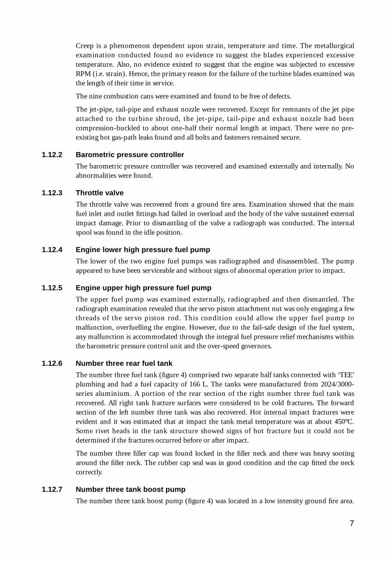
1.12.6 Number three rear fuel tank
The number three fuel tank (figure 4) comprised two separate half tanks connected with ‘TEE’plumbing and had a fuel capacity of 166 L. The tanks were manufactured from 2024/3000-series aluminium. A portion of the rear section of the right number three fuel tank wasrecovered. All right tank fracture surfaces were considered to be cold fractures. The forwardsection of the left number three tank was also recovered. Hot internal impact fractures wereevident and it was estimated that at impact the tank metal temperature was at about 450°C.Some rivet heads in the tank structure showed signs of hot fracture but it could not bedetermined if the fractures occurred before or after impact.
The number three filler cap was found locked in the filler neck and there was heavy sootingaround the filler neck. The rubber cap seal was in good condition and the cap fitted the neckcorrectly.
1.12.7 Number three tank boost pump
The number three tank boost pump (figure 4) was located in a low intensity ground fire area.
7
The inlet pipe was fractured and the fracture was indicative of overload failure. There weresoot deposits in the inlet pipe tube indicative of flash-over from ground fire. Only minorburning was evident on the outer surface of the pump. The outlet was intact, with a section ofhose attached. Some burning near the outlet was evident. The area around the main gasketshowed signs of external fire.
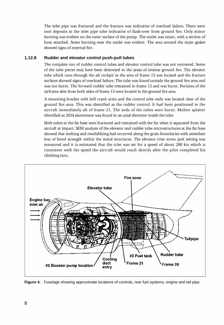
1.12.8 Rudder and elevator control push-pull tubes
The complete run of rudder control tubes and elevator control tube was not recovered. Someof the tube pieces may have been destroyed in the areas of intense ground fire. The elevatortube which runs through the aft cockpit in the area of frame 13 was located and the fracturesurfaces showed signs of overload failure. The tube was found outside the ground fire area andwas not burnt. The forward rudder tube remained in frame 13 and was burnt. Portions of theairframe skin from both sides of frame 13 were located in the ground fire area.
A mounting bracket with bell crank arms and the control tube ends was located clear of theground fire area. This was identified as the rudder control. It had been positioned in theaircraft immediately aft of frame 21. The ends of the tubes were burnt. Molten splatteridentified as 2024 aluminium was found in an axial direction inside the tube.
Both tubes in the fin base were fractured and remained with the fin when it separated from theaircraft at impact. SEM analysis of the elevator and rudder tube microstructures at the fin baseshowed that melting and resolidifying had occurred along the grain boundaries with attendantloss of bond strength within the metal structures. The elevator trim screw jack setting wasmeasured and it is estimated that the trim was set for a speed of about 280 kts which isconsistent with the speed the aircraft would reach shortly after the pilot completed hisclimbing turn.
Figure 4. Fuselage showing approximate locations of controls, rear fuel systems, engine and tail pipe.
8
1.12.9 Fire extinguishing system
Portions of the panels containing both front and rear cockpit fire-bottle firing buttons werelocated. The condition of the front firing button and the remains of the system precluded anydetermination as to whether or not the fire extinguishing system had been activated by thepilot. The rear cockpit fire-bottle firing button cover was lock-wired in the closed position.
Both fire extinguisher bottles were recovered. The firing heads, which were broken from thebottles, were recovered and matched to the bottles by matching fracture surfaces. The firingheads have within them an electrical firing mechanism below which is located a thin metaldiaphragm which seals the extinguishing agent inside the bottle. When the firing button ineither cockpit is activated, the cartridges in both bottles are fired simultaneously and theextinguishing agent is directed into the engine bay area.
The diaphragm of one firing head was dented from the striker. Evidence of the cartridge havingfired was shown by the remains of green/yellow nitrate based explosive primer-mix in thecylinder and piston top. The external electrical contacts were impact damaged.
The striker of the second firing head had penetrated the diaphragm. The associated cartridgeand connections were lost. There was no evidence of the green/yellow primer mix in thepiston/cylinder cavity.
1.13 Medical and pathological information
There is no evidence that the pilot had any prior medical or psychological condition whichmight have contributed to the accident.
1.14 Fire
Examination of the wreckage and impact area revealed evidence of in-flight and ground fire.Witnesses who viewed the aircraft just prior to impact confirmed the presence of fire in the rearof the aircraft. The in-flight fire zone is shown in figure 4. Also shown is the interrelationship ofthe engine, the number three fuel tank, the number three tank boost pump and the rudder andelevator flight control tubes.
The fire was confined to the area between frames 21 and 24. Evidence of extreme temperaturesand in-flight fire was identified on all major structures aft of frame 24, whereas evidence ofrelatively lower temperatures was revealed forward of frame 21 (engine bay). This wasconfirmed by the following observations:
• Deposits of combustion products were found throughout the number three fuel tank bay.
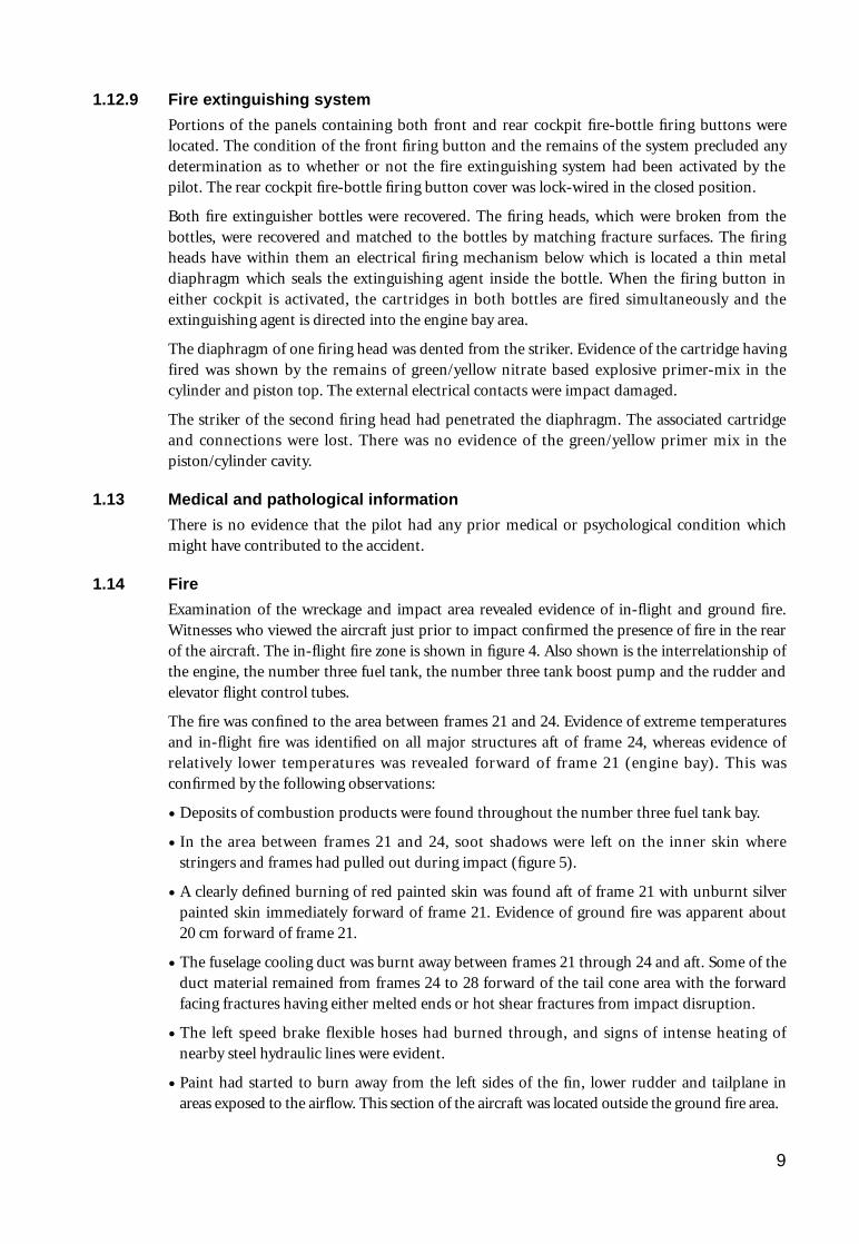
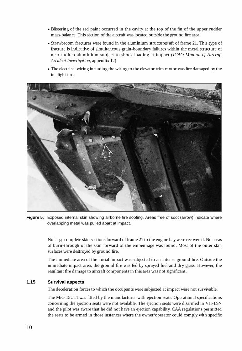
• In the area between frames 21 and 24, soot shadows were left on the inner skin wherestringers and frames had pulled out during impact (figure 5).
• A clearly defined burning of red painted skin was found aft of frame 21 with unburnt silverpainted skin immediately forward of frame 21. Evidence of ground fire was apparent about20 cm forward of frame 21.
• The fuselage cooling duct was burnt away between frames 21 through 24 and aft. Some of theduct material remained from frames 24 to 28 forward of the tail cone area with the forwardfacing fractures having either melted ends or hot shear fractures from impact disruption.
• The left speed brake flexible hoses had burned through, and signs of intense heating ofnearby steel hydraulic lines were evident.
• Paint had started to burn away from the left sides of the fin, lower rudder and tailplane in areas exposed to the airflow. This section of the aircraft was located outside the ground fire area.
9
• Blistering of the red paint occurred in the cavity at the top of the fin of the upper ruddermass-balance. This section of the aircraft was located outside the ground fire area.
• Strawbroom fractures were found in the aluminium structures aft of frame 21. This type offracture is indicative of simultaneous grain-boundary failures within the metal structure ofnear-molten aluminium subject to shock loading at impact (ICAO Manual of AircraftAccident Investigation, appendix 12).
• The electrical wiring including the wiring to the elevator trim motor was fire damaged by thein-flight fire.
Figure 5. Exposed internal skin showing airborne fire sooting. Areas free of soot (arrow) indicate whereoverlapping metal was pulled apart at impact.
No large complete skin sections forward of frame 21 to the engine bay were recovered. No areasof burn-through of the skin forward of the empennage was found. Most of the outer skinsurfaces were destroyed by ground fire.
The immediate area of the initial impact was subjected to an intense ground fire. Outside theimmediate impact area, the ground fire was fed by sprayed fuel and dry grass. However, theresultant fire damage to aircraft components in this area was not significant.
1.15 Survival aspects
The deceleration forces to which the occupants were subjected at impact were not survivable.
The MiG 15UTI was fitted by the manufacturer with ejection seats. Operational specificationsconcerning the ejection seats were not available. The ejection seats were disarmed in VH-LSNand the pilot was aware that he did not have an ejection capability. CAA regulations permittedthe seats to be armed in those instances where the owner/operator could comply with specific
10

requirements. At the time of the occurrence none of the operators of MiG 15 aircraft inAustralia maintained an ejection seat capability in their aircraft.
1.16 Prior event
On 27 November 1992, immediately after takeoff from Avalon Victoria, the pilot was reportedto have experienced fluctuating jet pipe temperature gauge readings. A definitive explanationof what occurred could not be obtained as differing versions of the occurrence were related tothe investigation team. It was reported that upon noticing that the jet pipe temperature hadincreased to a reading above the maximum allowable for the engine, the pilot immediatelyretarded the throttle to idle. The jet pipe temperature reduced to a reading of zero thenfluctuated. When the throttle was advanced the jet pipe temperature readings returned tonormal. Changes in throttle settings produced normal readings. The pilot assessed thesituation as a gauge problem and continued the flight. The incident was reported to themaintenance organisation as a possible gauge problem. A post-flight inspection did not revealany specific fault and an engine run confirmed that the gauge was operating to specifiedrequirements. It was suspected by maintenance personnel that moisture ingress into one of theelectrical connections may have caused the erratic indications as the aircraft had been parkedoutdoors while awaiting repairs at Avalon. This malfunction was not recorded in any aircraftlogbook nor was there a record of the actions taken by maintenance personnel.
1.17 Fuselage fire detection system
The aircraft was fitted with a fuselage over-temperature or fire detection system. This systemwas fitted on the forward face of frame 21. As the in-flight fire did not extend forward of frame21, the fire detection system would not have activated. The temperature sensing range abovewhich the cockpit warning is activated is 140–160°C.
1.18 Aircraft documentation
The MiG 15UTI was purchased in Poland and had been operated by the Polish Air Force.Documentation which would normally accompany an aircraft when a change of ownershipoccurred was not available for review during the investigation. The owner stated that when theaircraft was purchased, the Polish Air Force would not release any maintenance documentationor logbooks pertaining to the aircraft.
A document with a Polish Ministry of Trade and Commerce letterhead dated in Warsaw on 1December 1989 provided the following information:
• The aircraft airframe 1A06015 had 1,582 hours total time in service, with a time since lastinspection of 450 hours. Last inspection was in 1984.
• The engine SN 52644 had a TTIS of 1,167 hours and a TSI of 199 hours. Last inspection wasin 1986.
• No defects stated at time of retirement of all aircraft and engines.
• All modifications applied in the Polish Air Force are incorporated.
The document did not provide any information on the type of inspection carried out nor did itindicate what type of inspection was next due or when.
The Australian logbook shows that the following ‘lifed’ components were installed in VH-LSN:generator, starter, system hydraulic pump, aileron hydraulic pump, upper fuel pump, lowerfuel pump, barometric control, throttle valve and HP shut-off cock. The logbook annotationindicates that all the components were installed on the aircraft at 1,383 hours time since newand had a mandatory component life of 1,800 hours. At installation, these component timessince overhaul as annotated in the Australian logbooks were 0 (zero) hours with the
11

components due for removal at 3,183 airframe hours. The components were installed on theengine and/or airframe in Poland and there was no documentation to support the datacontained in the logbooks of VH-LSN.
Information received from the CAA states that the main fuel pumps were identified for inspectionevery 900 hours TIS and the engine hot end required inspection at intervals of 200 hours.
Unfortunately, the data relating to individual airframe, engine and component lives cannot beused with confidence. This data is subject to an Australian Federal Police investigation as it issuspected of being forged.
1.19 Permit to fly
A CAA Permit to Fly for historical and ex-military aircraft was issued on 3 April 1992 and wasvalid for one year. Sub-paragraph (d)(ii) of the permit states the following limitation:
The aircraft shall not be flown over a populous area except that, where a positioning flight isrequired, the aircraft may be flown over a populous area to the minimum extent necessaryalong a route approved by the Authority.
Sub-paragraph (c) which prohibits the carriage of passengers was deleted and under theSpecial Conditions section paragraph 2 was added which states:
The carriage of passengers is permitted only for the purpose of regulation 134(1) (bc) of theCivil Aviation Regulations.
Civil Aviation Regulation 134(1)(bc)(i) states:
134. (1) The Authority or an authorised person may give permission to fly an aircraft inAustralian territory on a particular flight, or on all flights during a specified period, for thepurpose of:
(bc) carrying passengers on a flight of the aircraft, being a flight that:
(i)begins at a particular place and ends at the same place without the aircraftlanding at any other place during the flight…
1.20 Aircraft test flight
The accident pilot flew a test flight on VH-LSN on 14 March 1992 at RAAF Richmond. Thefollowing extracts are taken from the test flight schedule document:
• stalling flaps retracted – 113K (IAS)
• stalling flaps extended T/O – 110k
• stalling flaps extended landing – 110k
• stalling flaps extended landing gear down – 110k
A note with reference to the stalls on the document states: ‘Wallows longitudinally below 120k-125k clean & 115k (approach config). A/C not flown to point of stall (for safetyconsiderations)’. The test flight document did not state at what altitude or weight the stallportion of the flight was conducted.
In the comments section, paragraph 12 of the document, the following note was inscribed:‘Stable in all planes >160k clean (min. man. IAS)’. The comments in brackets are believed to bein reference to the minimum manoeuvring indicated air speed.
1.21 CAA endorsement requirements
Civil Aviation Orders, part 40, section 40.1.0 details the requirements for the issuing of typeendorsements for specific aeroplanes. Subsection 6.1 which was current at the time the pilotreceived his endorsement identifies the specific requirements for the issue of a typeendorsement for aircraft such as the MiG 15UTI. Subsection 6.1 states in part:
12
6.1 – The endorsement of a pilot licence for a type or category of aeroplane not exceeding 5,700kg maximum take-off weight shall be conditional upon the applicant undergoing training andpasses(sic) tests of his or her knowledge of the operating limitations of the type or category ofaeroplane and of his or her ability to perform all normal and emergency flight manoeuvres inthe particular type or category.
In addition, Flying Operations Instructions No. 13-1 titled ‘Operation of ex-military aircraft’issued by the CAA contains information concerning the endorsement requirements for pilotsflying ex-military aircraft. The MiG 15UTI is classed as a Group C aircraft in that document.With reference to endorsement training the FOI states:
4.6 – To gain endorsement on a Group C aeroplane, an applicant shall demonstrate to a personspecifically approved by a Manager, Flying Operations of the CAA that he/she has completed aflying training sequence in a suitable two-place dual control aeroplane. Aeroplanes which havebeen assessed as suitable for the flying training for turbojet aeroplanes include the DH115Vampire T Mk 35 and the dual place MiG 15 and 17. On completion of this training theapplicant shall carry out 6 hours of command flight time under the direct supervision of anapproved person on the aeroplane type for which the endorsement is sought, including at least6 take-offs and 6 landings to a complete stop.
Part 3.5 of the FOI details the currency requirements of a pilot of a Group C aeroplane andstates in part that the pilot must have flown one hour on type with at least three takeoffs andthree landings in the preceding 90 days or if he has not met these requirements he mustundertake supervised training or obtain the approval of a CAA examiner prior to conductingunsupervised flights.
At the time the pilot requested an endorsement and at the time of the accident, FOI 13-1formed part of the instructions issued by the Authority to their officers. The documentcontains obligatory words such as ‘shall’.
Civil Aviation Regulations require the pilot, within the period 90 days immediately before theday of the proposed flight, to have carried out at least three takeoffs and three landings whileflying an aeroplane as pilot in command. The pilot met this requirement by virtue of flyinganother aircraft type.
1.22 CAA documents
The CAA regulates the operation of aircraft, pilot qualification requirements and maintenancerequirements in part by promulgating orders and regulations, issuing licences and permits, andmonitoring civil aviation activity. With respect to the operation of ex-military or warbirdaircraft, the CAA has issued a separate Permit to Fly, FOI 13-1 and AWI. The FOI and AWIwere produced by the CAA to provide direction and guidance for its staff and unlessspecifically requested are not made available to an aircraft owner or operator. During theinvestigation, it was determined that some operators and pilots of ex-military aircraft were notaware of the contents of the various CAA documents which detail flight restrictions andrecommend the training requirements of that class of aircraft.
1.23 Video tape
A home video was taken of the aircraft during the start, taxi to the runway, the takeoff andclimb, portions of the flight, and the descent of the aircraft just prior to impacting the ground.It showed the aircraft taxiing onto the runway and commencing an immediate takeoff. Theacceleration appeared uniform. As the aircraft lifted off it was levelled at about 15 ft and thelanding gear was raised. The aircraft then commenced a smooth, coordinated climb and leftturn to an altitude of about 1,200 ft AGL. The aircraft then continued in a gradual left turn,away from the airfield. A puff of dark smoke was observed behind the tail pipe shortly after theaircraft completed its climbing turn. As the flight progressed the height appeared to remain
13
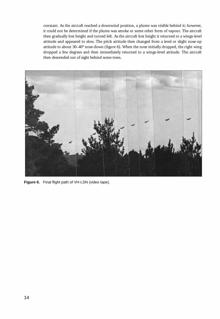
constant. As the aircraft reached a downwind position, a plume was visible behind it; however,it could not be determined if the plume was smoke or some other form of vapour. The aircraftthen gradually lost height and turned left. As the aircraft lost height it returned to a wings-levelattitude and appeared to slow. The pitch attitude then changed from a level or slight nose-upattitude to about 30–40° nose-down (figure 6). When the nose initially dropped, the right wingdropped a few degrees and then immediately returned to a wings-level attitude. The aircraftthen descended out of sight behind some trees.
14
Figure 6. Final flight path of VH-LSN (video tape).

2. ANALYSIS
2.1 Introduction
The investigation focused on the flight of the aircraft which led to the ground impact. Theevidence gathered was analysed in detail in an attempt to determine and understand the eventsleading to the pilot’s apparent loss of control. Aircraft operational data specific to the MiG15UTI was sparse and where available its origin could not be verified. Because of the limitedinformation on the MiG 15UTI, the documentation including the logbooks for VH-LSN wasreviewed in an attempt to determine the status of various aircraft components and the impactthe component status may have had on the occurrence. The CAA process of certifying theaircraft and providing pilot endorsements was reviewed.
2.2 In-flight fuselage fire
The effects of the in-flight fire on VH-LSN were contained in the aft fuselage. As such, areasonable conclusion to reach would be that the source of combustible material and theignition source were located in the aft fuselage. However, a flammable liquid leak (JetA1 orhydraulic oil) could be carried from the forward fuselage through to the tailpipe beforeencountering a suitable ignition source. With all aircraft systems working normally, suitableignition sources could be the hot metal of the nozzle guide vane casing and the turbine shroud,or hot engine exhaust gases. Hence, for this purpose of this analysis, all flammable liquidscarried on the MiG-15 aircraft were considered.
With the engine operating above ground idle, the gas temperatures in the jet pipe would be inexcess of 500°C. Even when considering the time taken to heat-soak the nozzle guide vanecasing and the turbine shroud, the temperature of these items would eventually exceed theauto-ignition temperature for JetA1 and MIL-H-5606C hydraulic oil (max. 230°C). However, ifthis assessment is incorrect, or the fuel vapour did not contact these hot surfaces, thetemperature of the surrounding air would be rapidly rising as it carries away heat from theengine hot section and jet pipe. Eventually, this air would be at the auto-ignition temperatureof the flammable liquid being considered, either within the confines of the cooling duct or as itmeets the engine exhaust gases aft of the tail pipe. Therefore, a flammable liquid leak from theforward fuselage or engine bay would eventually be ignited. With the effects of the ram air inthe cooling duct, the temperature of the burning fuel (estimated to be a minimum of 1,300°C)would be well in excess of that required to melt the cooling duct and jet pipe lining material.This fire would rapidly burn into the aft fuselage cavity and weaken the elevator control rods.
Flammable liquid sources aft of frame 21 are the number three fuel tank and transfer piping,and the speed brake actuator hydraulic system. The number three tank normally holds 166 L offuel. However, this tank was not refuelled at Canberra before the accident flight. As it was lastfilled at Nowra, prior to the flight to Canberra, and as it feeds first when holding fuel, thenumber three tank must have been empty on the accident flight. Even considering tankunusable fuel (estimated to be less than 1 L) or possible fuel spillage accumulating in the tankaccess hatch (less than 1 L), there is insufficient fuel to sustain a fire of sufficient energy to burnaround the cooling duct and melt the control rods. Therefore, the number three fuel tanksystem was not the source of the flammable liquid of the in-flight fire.
The speed brake actuator hydraulic lines are steel and are located in the same region of the aftfuselage as the control rods. For this hydraulic system to be the source of flammable liquid,these lines would have to be compromised. This could occur by failure due to a pre-existingdefect or being severed. A ruptured hydraulic line would spray fluid around the fuselage cavity,
15

creating the mist required for ignition. However, the normal operating temperature of thiscavity would be below the auto-ignition temperature of hydraulic fluid. Further, as the aftfuselage cavity around the cooling duct would not be well ventilated, there is little likelihoodthat a suitable air/fuel mixture could exist for combustion to occur. Accordingly, under thesecircumstances, the speed brake hydraulic system is unlikely to have been the source of fuel forthe in-flight fire.
The in-flight fire occurred on VH-LSN in the fuselage aft of frame 21. As a result of this fire,the elevator control rod was burnt, or melted, and control of the aircraft was lost. Examinationof the evidence available failed to positively identify the source of flammable liquid and theignition source responsible for the fire. However, based on the circumstances of the fire, areasonable hypothesis can be drawn. This hypothesis is that a JetA1 fuel or MIL-H-5606Chydraulic oil leak from forward of frame 21 ignited in the airframe cooling duct from contactwith either the hot metal of the turbine section of the engine, hot gases in the duct, or theengine exhaust aft of the aircraft. This fire could have been contained to the cooling duct dueto the lack of a suitable air/fuel mixture forward of frame 21. The fire quickly burnt throughthe cooling duct wall, and subsequently weakened the elevator control rod.
2.3 Turbine blade failures
The metallurgical analysis of the turbine blades conducted by the CASA Materials EvaluationFacility concluded that they had failed through creep rupture. Failure resulted in the loss of25–30 mm from each blade tip. The damage was consistent across the nine sample bladesavailable for examination.
The Materials Evaluation Facility report stated that the creep phenomenon is dependent uponthree variables—temperature, strain and time. This report stated there was no evidence thatthese blades experienced excessive temperature during their operating life. Witness commentshave highlighted instances where the jet pipe temperature apparently exceeded the specifiedlimits. As metallurgical examination failed to identify crystalline structure changes due toexcessive temperature, the instances of over-temperature were obviously very minor, or weregauge problems as suggested by the pilot. Notwithstanding this uncertainty, established turbineblade theory states that the operating life of a blade is reduced when it experiencestemperatures in excess of the specified maximum value. Hence, if these turbine bladesexperienced temperatures in excess of the maximum specified limits, they would have areduced operating life.
The post-accident review of both fuel pump over-speed governors found no evidence ofmalfunctioning. Therefore, excessive strain, caused by out-of-tolerance rotor RPM, should nothave contributed to the observed blade creep.
With temperature and strain removed as contributing factors to the creep failure of theseblades, their operating life becomes the prime consideration.
In simple terms, creep is the gradual lengthening of a material subjected to temperature, strainand time. A turbine blade suffering creep will eventually contact the outer casing, resulting intip rub. Turbine blade tip rub is typically discernible through longer engine start and shorterengine run-down times due to increased friction in the engine. Such symptoms should bediscernible to an experienced pilot and would, as a minimum, result in an inspection of theengine by qualified maintenance personnel. However, no evidence exists to indicate whetherthe pilot of VH-LSN was aware of the tip rub occurring in his engine, or whether he discussedthis problem with the aircraft owner or maintenance organisation.
16

2.4 Airframe and aircraft component documentation
When the aircraft was imported from Poland it was not accompanied by any documentationspecific to the defective engine-driven fuel pump. The Australian aircraft logbooks indicatethat the fuel pump was installed as a 0 (zero) time component at 1,383 airframe hours or 216hours before the accident with an overhaul life of 1,800 hours. Due to the fact that the figuresused by the owner could not be verified, the assumption of time remaining on the componentmight be in error by several hundred hours and the component might have been near timeexpiry when the aircraft was imported to Australia. This premise is further supported by theallegations that the original figures were forged.
During the examination of the aircraft documentation and CAA approval process, it wasevident that the logbook documentation for the aircraft was almost non-existent and in theinstances of time life components, the times inserted into the logbooks could not be verified orvalidated. Nor could it be determined how the time of installation, time since overhaul ormandatory overhaul life on the component were determined. The CAA provided the Bureauwith information on some time life components which varied significantly from the timesinscribed in the Australian logbooks. Even though the times were at variance, the CAA issued aPermit to Fly for the aircraft.
It is not uncommon for airframe and engine sub-components to be changed in-servicewithout ensuring that the time remaining is matched to other components; thus it is possiblethat none of the components other than the engine and airframe had the hours remaining aslisted in the Australian aircraft logbooks.
2.5 Flight crew qualifications for the operation of ex-military aircraft
At the time the pilot obtained his CAA authority to fly the MiG 15UTI on test flights and later,when he obtained his endorsement, there were no regulations or orders specific to the MiGaircraft. There were, however, appropriate regulations, orders and instructions within FlyingOperations Instructions No. 13-1 which provided specific guidance for CAA inspectors for theissuing of endorsements to pilots flying ex-military aircraft. In the case of the accident pilot,these instructions were not followed by the CAA inspectors, or if they were, documentation ofthe process was incomplete.
In addition to the FOIs not being followed, the files held by the CAA did not indicate whatprocess was used by them to determine whether or not the pilot was qualified to conduct thetest flights. If the CAA inspector considered the pilot qualified to conduct the test flights, thenhe should have granted written approval to the pilot to fly the MiG on the test flight underRegulation 66(4) prior to the test flights being conducted.
When the pilot did request an endorsement, he was instructed by a CAA inspector to obtainthe signature of a CFI on a certificate of endorsement, approval and rating. The pilot wasadvised that this was a formality. The certificate was then signed by an individual who did nothave any knowledge of the operation of the MiG aircraft. The CAA accepted the endorsementdocument. Thus, the pilot was endorsed on type without anyone in authority ensuring that heunderstood the normal and emergency operation of the aircraft. Anecdotal evidence suggeststhat the pilot was aware of the limitations of the MiG 15UTI and was cautious in his approachto piloting the aircraft.
2.6 Ex-military aircraft operations
A number of inconsistencies were identified during the investigation which indicated thatsome owners, operators, pilots and CAA field inspectors were probably not conversant with theorders, regulations or instructions governing the operation of ex-military aircraft. Some ofthese issues were:
17

• The CAA issued a Permit to Fly for test flight purposes even though the owner of the aircraftcould not provide detailed records of the aircraft history. Times entered into the Australianaircraft logbooks could not be verified.
• The CAA did not document the process it applied when approving the pilot to test fly theaircraft.
• While the test flight Permit to Fly was in effect, the aircraft was flown for other than testflight requirements and the carriage of other crew and passengers occurred.
• On the accident flight the pilot planned a city scenic flight which would place the aircraftover a built-up area, which was not in accordance with the restrictions of the existing Permitto Fly.
Based on discussions with various individuals, it is probable that the inconsistencies identifiedabove were not an intentional disregard of orders, regulations and instructions but were,rather, well-intentioned efforts in support of the ex-military aircraft movement. The MiG wasa new arrival in Australia and its appearance on the aviation registry brought to Australia anaircraft of historical significance. What the above events do emphasise is the importance for allthe groups involved in aviation activities, especially those which are not conventional in nature,to ensure that they are fully conversant with all the regulations governing their particularactivity.
During the investigation it became apparent that there is a need to consolidate all orders,regulations and instructions which pertain to aircraft generally referred to as ex-military orwarbirds. Aircraft flown in this category generally do not meet CAA certification requirementsas the aircraft were built for a specific military role. As in early fighter aircraft, their service lifeexpectancy was often low. Because of this short life expectancy, design criteria often did nottake into consideration the high stresses imposed on the aircraft during their extended militaryoperation, especially where the aircraft were used for training.
Aircraft such as the MiG 15UTI entered military service 40–45 years ago. The technology usedin the production of jet aircraft was in its infancy and cannot be compared to the second orthird generation of military jet aircraft operated today. These aircraft may appear to besimplistic in construction when compared to modern aircraft, but a pilot operating a modernaircraft has the benefit of multiple backup and warning systems not available in older aircraft.During the investigation it was apparent that there were inconsistencies in the application andunderstanding of the orders, regulations and instructions applicable to the operation of ex-military aircraft. In view of the inconsistencies identified during the investigation, the Bureaubelieves there is a need for the CAA to develop Civil Aviation Regulations and Civil AviationOrders which are specific to the registration, certification and pilot endorsements for all ex-military aircraft flown with an Australian registration.
18

3. CONCLUSIONS
3.1 Findings
1. The aircraft was within operational weight and centre-of-gravity limitations.
2. The pilot held a MiG 15UTI endorsement.
3. The CAA did not document the pilot test flight approval which was granted underRegulation 66.
4. The CAA did not issue the pilot’s MiG 15UTI endorsement in accordance with theexisting CAOs or CAA instructions as specified in FOI No. 13-1.
5. The pilot did not receive any dual training on the MiG 15UTI nor was any required.
6. There was no available documentation from the Polish Air Force concerning the lifehistory of the aircraft and its components.
7. Documentation concerning component installation, last inspection type and date, andnext inspection time, type and date as imported from Poland was not available.
8. The in-service time of the aircraft components could not be verified.
9. An in-flight fire occurred aft of frame 21 and because the area is not monitored by a firewarning or overheat sensing device, the pilot was probably unaware of the fire.
10. The in-flight fire burned the electrical wiring which resulted in the loss of elevator trimcontrol during flight.
11. The source of combustible material was probably located forward of frame 21.
12. The source of ignition of the combustible material was located aft of frame 21.
13. The effects of the resulting fire were restricted to aft of frame 21.
14. The in-flight fire weakened the elevator control tubes located in the fuselage cavity aft offrame 21.
15. The in-flight fire melted and burned the rudder and elevator control tubes which led touncontrolled flight and ground impact.
16. The ejection seats were disarmed and the pilot was aware that he did not have an ejectioncapability.
3.2 Significant factors
1. There was probably an undetected flammable fluid leakage from forward of frame 21.
2. This flammable fluid ignited and burned in the cooling duct, destroying this duct andraising the temperature of the fuselage cavity behind it significantly.
3. No overheat or fire detection sensors were installed in the area of the fire.
4. The melting and burning of flight controls deprived the pilot of control of the aircraft.
19

4. SAFETY ACTION
4.1 Safety action taken
During the course of the investigation the Bureau of Air Safety Investigation made thefollowing recommendations.
IR930105
It is recommended that the Civil Aviation Authority produce a single publication whichbrings together all of the various requirements which relate to the operation of aircraftissued with a Permit to Fly under Civil Aviation Regulation 134.
The document should include all relevant information which is currently contained inAirworthiness Instructions, Flying Operations Instructions, Civil Aviation Orders, CivilAviation Regulations and the General Permission issued in relation to Regulation 134.This single document should be made available to the public.
IR930108
It is recommended that the Civil Aviation Authority review its procedures that relate tothe use of ejection seats in civil registered aircraft to ensure that:
• information on the requirements for ejection seats is included in documentation thatis readily available to the public; and
• the CAA’s approach to ejection seats is standardised.
IR930109
It is recommended that the Civil Aviation Authority amend the General Permissionunder Regulation 134, CAO 29.4 para. 4.1f and the Permit to Fly document to prohibitthe carriage of non-essential passengers or crew on display flights in ‘warbird’ aircraft,which are not designed for the carriage of passengers.
A collective response was received for interim recommendations IR930105, IR930108and IR930109, which stated in part:
we are hosting an Ex-military Aircraft Conference in Canberra on 15 July and it isexpected that all of the above issues will be considered at that meeting.
IR930107
It is recommended that the Civil Aviation Authority remind all operators of aircraftoperating on a Permit to Fly under Regulation 134, of their obligation to comply withthe restrictions contained in the Permit to Fly and to standardise the interpretation ofthe restrictions among the various CAA offices, in an effort to ensure that all personsinvolved are aware of the restrictions.
The response from the CAA in part stated:
A new Permit to Fly document is being developed in consultation with the ‘warbird’industry. A meeting of 85 representatives of the industry was held on 15 July 1993 whichcovered the points raised in the Interim Recommendation amongst other matters. Whenthe new permit is finalised, existing permits will be withdrawn and operators will bereminded of their obligations under the Permission to fly these aircraft.
20

IR930286
The Bureau of Air Safety Investigation recommends that the Civil Aviation Authority:
1. introduce a mandatory requirement to strip-inspect/overhaul the upper and lowerfuel pumps of the engines fitted to MiG 15 aircraft to ensure integrity of assembly andtheir subsequent operation; and
2. introduce and detail repetitive inspection/overhaul requirements for the upper andlower fuel pumps of the engines fitted to MiG 15 aircraft.
The response from the CAA stated:
We have discussed your fuel pump concerns with the industry organisations concerned,with our specialists and with our regional inspection staff.
The matter is complicated by the fact that we do not know why the internalmechanism of the pump became disassembled. Your further advice on the matterwould be appreciated. If it was caused by a mistake in some earlier strip down there isa telling argument that the risk is only increased by further attempts to take the pumpsapart. As you know, it is common aeronautical practice to carry out regularperformance checks to assess the adequacy of equipment and, in certain cases, thisincludes the complete engine. Overhauling is but one way to be assured of mechanicalperformance and may not be appropriate or necessary in all cases.
In this instance, there is a direct correlation between indicated EGTs and pumpperformance which should flag a tendency for over-fuelling. Subsequent maintenanceinvestigation associated with pump set up and isolation valve setting should, in turn,have identified the problem.
AD/MiG15/1 specifically addresses the fuel pump set up as requirement 3.
Please be assured that the Authority is well aware of our responsibilities with respect tothis issue and that aircraft will not be released for flying until we are satisfied that thisarea has been adequately addressed.
R930298
The Bureau of Air Safety Investigation recommends that the Civil Aviation Authorityreview the procedures used to assess the safe life of aircraft and components importedwithout adequate historical documentation before approving a Permit to Fly underRegulation 134.
The response from the CAA stated:
The Ex-Military Aircraft Conference, which was held in Canberra on 15 July 1993,identified the need for a Maintenance Review Panel to review the maintenanceprocedures not only of the MiG 15 aircraft but also all Australian registered ‘warbirds’aircraft.
The Authority accepts the recommendation and has established a Maintenance ReviewPanel which is chaired by a senior CAA Officer and consists of representatives from theAuthority and the Warbirds Association.
The Panel is developing a means to be able to establish an appropriate level of integrityfor entry into service and continuing airworthiness of this class of aircraft.
21

R930299
The Bureau of Air Safety Investigation recommends that the Civil Aviation Authority:
1. introduce a standardised process for approving pilots to carry out training on aircraftoperating on a Permit to Fly under regulation 134; and
2. adopt standard endorsement requirements for pilots who wish to operate aircraft on aPermit to Fly under regulation 134, with special attention to training, experience andcurrency.
The response from the CAA stated:
This Authority agrees with R930299 and will take action to implement therecommendations contained therein.
BASI note: The Civil Aviation Safety Authority has undertaken to incorporate all the Bureauof Air Safety Investigation recommendations in a new publication titled Guidance Material ofIntending Operators of Historic or Ex-Military Aircraft.
22