
Middle East India Deepwater Pipeline (MEIDP) findings and ... faculteit/Afdelingen... · Middle...
7
Middle East India Deepwater Pipeline (MEIDP) – findings and implications of the 2013 reconnaissance survey I.F.J. Nash, Peritus International Ltd, Pertius International Ltd, Export House, 6 Cawsey Way, Woking, Surrey, UK, GU21 6QX [email protected] Abstract The Middle East to India Pipeline (MEIDP) will provide an economic and secure source of gas for India, where the demand for energy will continue to increase over the coming decades. The proposed pipeline will be the deepest major infrastructure pipeline laid with water depths exceeding 3000m for significant sections of the 1200km route. This paper aims to present the findings of the 2013 geophysical reconnaissance survey with particular focus on the geohazard areas that have to be crossed including the Omani and Indian Continental slopes, the Indus Fan, the Owen Fracture Zone and the potential location of compression facilities on the Qalhat seamount. Examples of data will demonstrate the challenges that need to be overcome in laying the pipe in these geohazard zones. The results of the survey will be discussed together with the process required to identify a feasible route and necessary intervention works to bring this project closer to reality. Introduction In order to more clearly define the pipeline route and understand the geohazard areas that have to be crossed, SAGE commissioned Peritus to define and oversee a reconnaissance survey campaign to cover the full 1200km route. This entailed defining a primary route and numerous alternative subroutes block areas where detailed investigation was required to allow multiple route options to be investigated. Five block areas were of particular interest: Omani and Indian Continental slopes; the Indus Fan; the Owen Fracture Zone where the Arabia-India plate boundary meet and the potential location of compression facilities on the Qalhat seamount. The MEIDP Reconnaissance survey combines the route corridor and Area/Block surveys into a single geophysical campaign as detailed in Figure 1. Figure 1 MEIDP Geophysical Survey Campaign
Transcript of Middle East India Deepwater Pipeline (MEIDP) findings and ... faculteit/Afdelingen... · Middle...

Middle East India Deepwater Pipeline (MEIDP) – findings and implications of the 2013 reconnaissance survey I.F.J. Nash, Peritus International Ltd, Pertius International Ltd, Export House, 6 Cawsey Way, Woking, Surrey, UK, GU21 6QX
Abstract The Middle East to India Pipeline (MEIDP) will provide an economic and secure source of gas for India, where the demand for energy will continue to increase over the coming decades. The proposed pipeline will be the deepest major infrastructure pipeline laid with water depths exceeding 3000m for significant sections of the 1200km route.
This paper aims to present the findings of the 2013 geophysical reconnaissance survey with particular focus on the geohazard areas that have to be crossed including the Omani and Indian Continental slopes, the Indus Fan, the Owen Fracture Zone and the potential location of compression facilities on the Qalhat seamount. Examples of data will demonstrate the challenges that need to be overcome in laying the pipe in these geohazard zones. The results of the survey will be discussed together with the process required to identify a feasible route and necessary intervention works to bring this project closer to reality.
Introduction In order to more clearly define the pipeline route and understand the geohazard areas that have to be crossed, SAGE commissioned Peritus to define and oversee a reconnaissance survey campaign to cover the full 1200km route. This entailed defining a primary route and numerous alternative subroutes block areas where detailed investigation was required to allow multiple route options to be investigated. Five block areas were of particular interest: Omani and Indian Continental slopes; the Indus Fan; the Owen Fracture Zone where the Arabia-India plate boundary meet and the potential location of compression facilities on the Qalhat seamount. The MEIDP Reconnaissance survey combines the route corridor and Area/Block surveys into a single geophysical campaign as detailed in Figure 1.
Figure 1 MEIDP Geophysical Survey Campaign
2
Middle East India Deepwater Pipeline (MEIDP) – findings and implications of the 2013 reconnaissance survey
I.F.J. Nash, Peritus International Ltd,
The objectives of the reconnaissance survey include the acquisition, processing, interpretation and reporting of appropriate hydrographic, geophysical, geological and geotechnical data as required to:
Establish seabed topography
Evaluation of seabed and shallow subseabed geological and geotechnical parameters
Identify and map potential geological features, geotechnical phenomena and environmental constraints that may have the potential to influence the pipeline routing, construction or operation of the proposed pipeline development.
The reconnaissance survey was executed by Fugro OSAE using the MV Fugro Gauss survey vessel, over a period of 49 days (excluding Mob and Demob) immediately preceding the onset of the Southwest monsoon, commencing in India, offshore the Gujurat coast on 2nd May and completing in Oman on 20th June. The Geophysical survey consisted of multibeam (MBES) bathymetric data acquisition using Knogsberg EM122 and EM710 equipment and Sub Bottom Profiles (SBP) using Innomar SES-2000 Deep equipment. Backscatter processing was also performed on the multibeam data to allow visualisation of seabed geology. In total 1780km of route corridor survey on seven route segments and 26,207 Sq km of block surveys in five feature areas were performed.
Safety and Security At least half the survey route was within the limit of Somali Pirate attacks recorded in 2010 and the whole route designated as a high risk area. Fugro employed a marine security company to develop a security plan in accordance with Best Management Practice 4 (BMP 4) and provide onboard vessel security against Pirate attack. The critical purpose of the security plan during the survey operation was to provide a deterrent through physical presence and observation operations; coordinate external security requirements to the survey team including early detection (day and night); provide a quick response to breaches of the exclusion zone around the survey vessel and to identifying and deterring potential attackers. The security measures took the form of four armed maritime guards being present on the vessel, together with static vessel hardening by razor wire at key locations on the vessel. Regular safety and security drills were held which included evacuation of personnel to the “Citadel” for protection. In total 9 safety drills were carried out during the survey operations. There were no Accidents, Incidents or Near Misses reported.
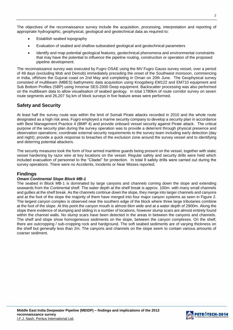
Findings Omani Continental Slope Block MB-1 The seabed in Block MB-1 is dominated by large canyons and channels coming down the slope and extending seawards from the Continental shelf. The water depth at the shelf break is approx. 100m. with many small channels and gullies at the shelf break. As the channels continue down the slope, they merge into larger channels and canyons and at the foot of the slope the majority of them have merged into four major canyon systems as seen in Figure 2. The largest canyon complex is observed near the southern edge of the block where three large tributaries combine at the foot of the slope. At this point the canyon mouth is almost 6km wide and at a water depth of 2900m. Along the slope there evidence of slumping and sliding in a number of locations, however slump scars are almost entirely found within the channel walls. No slump scars have been detected in the areas in between the canyons and channels. The shelf and slope show homogeneous sediments on the slope, between the canyon complexes. On the shelf, there are outcropping / sub-cropping rock and hardground. The soft seabed sediments are of varying thickness on the shelf but generally less than 2m. The canyons and channels on the slope seem to contain various amounts of coarser sediment.
3
Middle East India Deepwater Pipeline (MEIDP) – findings and implications of the 2013 reconnaissance survey
I.F.J. Nash, Peritus International Ltd,
Figure 2 Omani Continental slope Canyon Systems
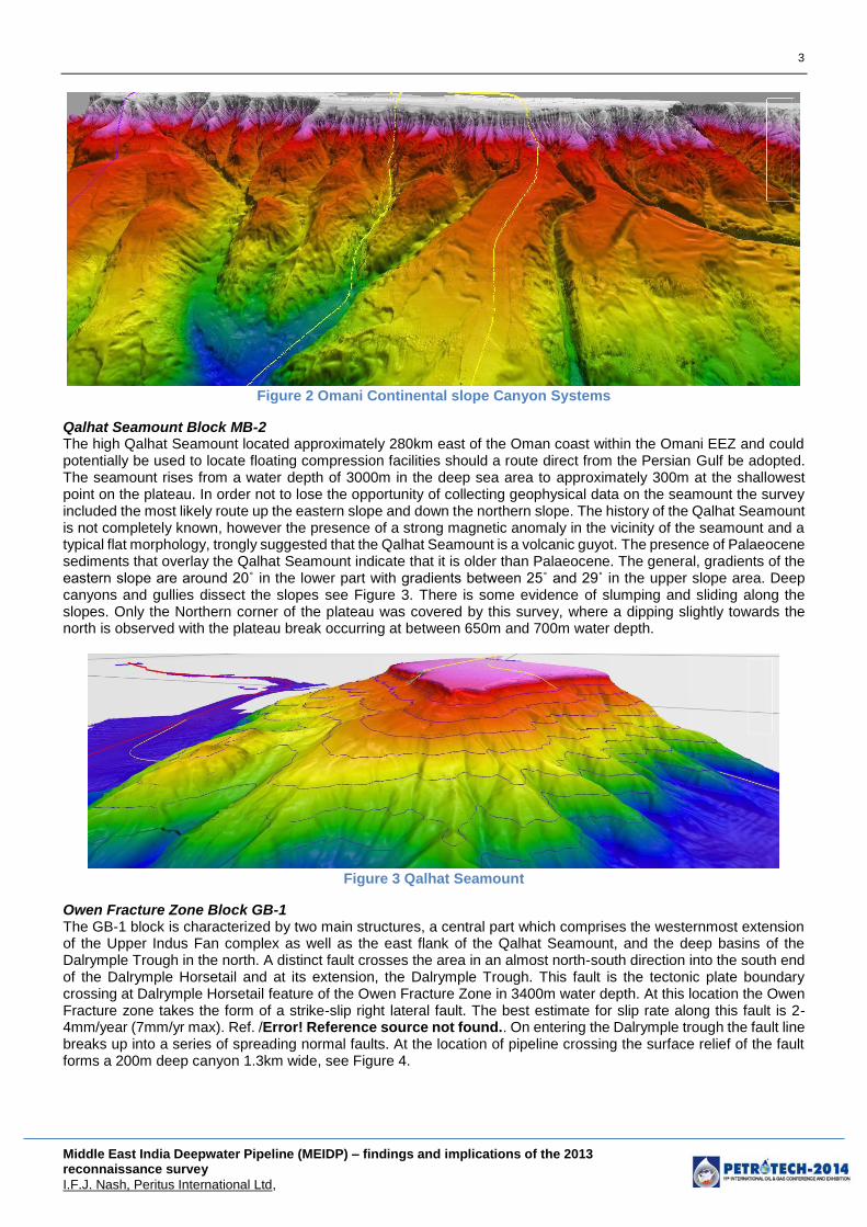
Qalhat Seamount Block MB-2 The high Qalhat Seamount located approximately 280km east of the Oman coast within the Omani EEZ and could potentially be used to locate floating compression facilities should a route direct from the Persian Gulf be adopted. The seamount rises from a water depth of 3000m in the deep sea area to approximately 300m at the shallowest point on the plateau. In order not to lose the opportunity of collecting geophysical data on the seamount the survey included the most likely route up the eastern slope and down the northern slope. The history of the Qalhat Seamount is not completely known, however the presence of a strong magnetic anomaly in the vicinity of the seamount and a typical flat morphology, trongly suggested that the Qalhat Seamount is a volcanic guyot. The presence of Palaeocene sediments that overlay the Qalhat Seamount indicate that it is older than Palaeocene. The general, gradients of the eastern slope are around 20˚ in the lower part with gradients between 25˚ and 29˚ in the upper slope area. Deep canyons and gullies dissect the slopes see Figure 3. There is some evidence of slumping and sliding along the slopes. Only the Northern corner of the plateau was covered by this survey, where a dipping slightly towards the north is observed with the plateau break occurring at between 650m and 700m water depth.
Figure 3 Qalhat Seamount
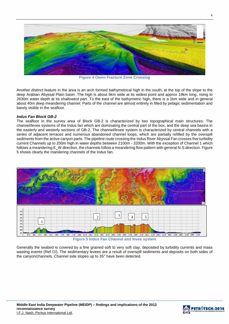
Owen Fracture Zone Block GB-1 The GB-1 block is characterized by two main structures, a central part which comprises the westernmost extension of the Upper Indus Fan complex as well as the east flank of the Qalhat Seamount, and the deep basins of the Dalrymple Trough in the north. A distinct fault crosses the area in an almost north-south direction into the south end of the Dalrymple Horsetail and at its extension, the Dalrymple Trough. This fault is the tectonic plate boundary crossing at Dalrymple Horsetail feature of the Owen Fracture Zone in 3400m water depth. At this location the Owen Fracture zone takes the form of a strike-slip right lateral fault. The best estimate for slip rate along this fault is 2-4mm/year (7mm/yr max). Ref. /Error! Reference source not found.. On entering the Dalrymple trough the fault line breaks up into a series of spreading normal faults. At the location of pipeline crossing the surface relief of the fault forms a 200m deep canyon 1.3km wide, see Figure 4.
4
Middle East India Deepwater Pipeline (MEIDP) – findings and implications of the 2013 reconnaissance survey
I.F.J. Nash, Peritus International Ltd,
Figure 4 Owen Fracture Zone Crossing
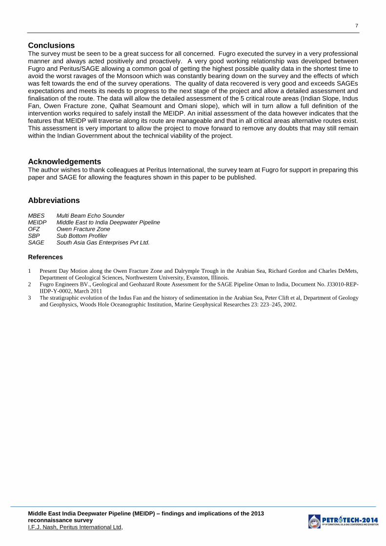
Another distinct feature in the area is an arch formed bathymetrical high in the south, at the top of the slope to the deep Arabian Abyssal Plain basin. The high is about 6km wide at its widest point and approx 19km long, rising to 2630m water depth at its shallowest part. To the east of the bathymetric high, there is a 1km wide and in general about 40m deep meandering channel. Parts of the channel are almost entirely in filled by pelagic sedimentation and barely visible in the seafloor. Indus Fan Block GB-2 The seafloor in the survey area of Block GB-2 is characterized by two topographical main structures: The channel/levee systems of the Indus fan which are dominating the central part of the box; and the deep sea basins in the easterly and westerly sections of GB-2. The channel/levee system is characterized by central channels with a series of adjacent terraces and numerous abandoned channel loops, which are partially refilled by the overspill sediments from the active canyon parts. The pipeline route crossing the Indus River Abyssal Fan crosses five turbidity current Channels up to 200m high in water depths between 2100m - 3200m. With the exception of Channel 1 which follows a meandering E_W direction, the channels follow a meandering flow pattern with general N-S direction. Figure 5 shows clearly the mandering channels of the Indus fan.
Figure 5 Indus Fan Chaneel and levee system
Generally the seabed is covered by a fine grained soft to very soft clay, deposited by turbidity currents and mass wasting events (Ref /2/). The sedimentary levees are a result of overspill sediments and deposits on both sides of the canyon/channels. Channel side slopes up to 35° have been detected.
1 2
3 4 5

5
Middle East India Deepwater Pipeline (MEIDP) – findings and implications of the 2013 reconnaissance survey
I.F.J. Nash, Peritus International Ltd,
Of the four channels crossed it is only channel 4 that appears to be recently active in geological time, with a potential activity date around the last sea level low during the Pleistocene era. Ref /3/
Figure 6 Indus Fan Channel 4 Crossing
Indian Continental Slope Block GB-3 The seabed in the survey area of Box GB-3 consists of a narrow shelf section at the eastern edge of the box and a broad area covering the continental slope in the middle and western part of the survey area. The water depth ranges from 70m at the East to around 150m at the shelf break. Towards the open sea the continental slope becomes the dominating morphological feature. The water depth ranges from 150m at the shelf break to around 2500m at the base of the slope. The upper slope area is dominated by numerous steep incised gullies with slopes of up to 30 ˚ observed near the shelf break (See slope map below). Down Slope most of them join together to form smaller canyons, which on her part forming mayor canyons. Between the canyons sediment ridges/mounts are developed. Slump deposits can be observed in MBES data which usually end up at the base of the slope contained within canyon walls
Figure 7 Indian Continental slope Canyon Systems
Implications Omani Continental Slope Two route options have considered feasible to cross the Omani Contiental slope, based on initial inspection. A northern route that utilises, in the main part, a broad promentry between two major canyons to to ensure a smooth decesnt onto the abyssal plain. A southern route utilises one of the canyon systems to route the pipeline to the abyssal plain. The slopes encountered by the northern route are generally less than 10° with a maximum slope at the shelf break of 20° as the pipeline passes into one of the numerous small gullies that characterise the shelf break. The southern route descends more quickly initially experiencing maximum slopes near the shelf break of arounf 30°, however once fully in the canyon system the general slopes are less than 10°. It is likely that as the seabed on both pipeline routes will require modification in the form of trenching to smooth the transition into the small gullies at the shelf break. The northern route may require some gravel berm support at it moves from its initial gully onto the promentry in approx. 700m water depth. The southern route whilst similar in average slope to the northern route, experiences much greater variation in slopes locally and may require span supports at numerous locations. Qalhat Seamount Two route have considered feasible to ascend and descend the Qalhat Seamount, based on initial inspection. A north western route (ascent) that utilises, in the main part, a straight gully feature to allow a smooth ascesnt from the

6
Middle East India Deepwater Pipeline (MEIDP) – findings and implications of the 2013 reconnaissance survey
I.F.J. Nash, Peritus International Ltd,
abyssal plain to the flat top of the seamount. A northeastern route utilises the northern most canyon systems on the eastern side to descend back to the abyssal plain. The slopes encountered by the north western route are generally less than 12° with a maximum slope midway down the gully of 22°. The north eastern route descends initially within the gully system where the general slopes are less than 12° with the maximum slopes near the shelf break and at the base of the seamont of around 25°. It is likely that as the seabed on both pipeline routes will require modification in the form of trenching to smooth the transition into the small gullies at the shelf break. The north eastern route may also require trenching in specific locations to protect the pipeline from impingement by debris flows from tributary canyons and gullies and improve the profile at the base of the seamount.. Owen Fracture Zone
The preliminary pipeline route determined during the survey activity has been used to perform an initial bottom roughness assessment of the pipeline, to determine the stress state and spanning condition of the pipeline in the areas of the OFZ. It is clear from the assessment made that the initial goals of the routing to: minimise spans; avoid areas of steep slopes; avoiding water depths greater than 3400m and give flexibility to the pipeline to accommodate a potential movement of the faulthave been achieved. The spans associated with the canyon of the Dalrymple Horsetail are relatively minor, having height less than 0.35m and lengths less than 70m. The maximum span height and length are associated with the relic channel of the Indus fan on the eastern edge of Block GB-1. At the pipeline crossing of the relic channel the anticipated installation span length is 120m with a height of 1.0m. The exact nature of optimum intervention has jet to be defined however given the size and nature of the spans predicted from the bottom roughness assessment it is most likely that vortex shedding stakes will be used for spans requiring remediation in the immediate vicinity of the main plate boundary fault, as it is clear that the flexibility afforded to the pipeline by the freespan will be beneficial in accommodating fault movements. Spans associated with the irregular seabed caused by the displaced blocks may best be remediated by mechanical supports or matresses. The long span associated with the relic channel may best be remediated by shoulder lowering using mas flow excavation techniques, providing the soils are suitable. Indus Fan The pipeline route across the Indus Fan runs predominantly from west to east. Given the general E-W nature of channel 1, the route tracks this channel to in the deepwater basin to its north in approximately 3050m water depth for 24km until a suitable crossing is afforded in a NW-SE direction. After crossing Channel 1 the pipeline route passes into the deepwater basin south of channel 1 and traversing ESE for 85km in this deep basin area crossing several infilled relic channels and channel loops in water depths between 2840m and 2940m before climbing to 2590m water depth over the final 3.5km to reach the N-S orientated channel 2. Channel 2 marks the start of the main N-S trending of the Indus Fan within Block GB-2 which contains 4 main channel features (channels 2-5). In the southern, deeper water part of the block, Channels 2-5 are spaced between 20km-30km from each other, diverging slightly as they meander their way from north to south. The exact nature of optimum intervention has yet to be defined however given the size and nature of the spans predicted from the bottom roughness assessment it is most likely that vortex shedding stakes will be used for spans requiring remediation in the immediate vicinity of the base of the channels. Spans associated with the irregular seabed caused by the channel flanks and extinct channel loops may best be remediated by mass flow excavation or mechanical trenching equipment. Mechanical supports or matresses may be used where span heights are small and where the foundation soils are adequate. Indian Continental Slope Two route options have considered feasible to cross the Indian Contiental slope, based on initial inspection. A southern route that utilises, in the main part, a broad promentry south of the main central canyon feature to allow a smooth ascesnt from the abyssal plain to the continental shelf. A northern route utilises one of the smaller canyon systems to the north of the main central canyon feature to route the pipeline to the continental shelf. The slopes encountered by the southern route are generally less than 5° with a maximum slope at the shelf break of 15° as the pipeline passes into one of the numerous small gullies that characterise the shelf break. The northern route climbs gently within the gully system where the general slopes are less than 10° with the maximum slopes near the shelf break of around 28°. It is likely that as the seabed on both pipeline routes will require modification in the form of trenching to smooth the transition into the small gullies at the shelf break. The northern route may require some gravel berm support at it moves from its initial gully onto the promentry in approx. 200m water depth. The northern route may also require trenching in specific locations to protect the pipeline from impingement by debris flows from tributary canyons and gullies. The southern route is very smooth and is unlikely to require significant span support or intervention, however evidence of surface slides on this route will need to be assess in more detail before required intervention can be determined.
7
Middle East India Deepwater Pipeline (MEIDP) – findings and implications of the 2013 reconnaissance survey
I.F.J. Nash, Peritus International Ltd,
Conclusions The survey must be seen to be a great success for all concerned. Fugro executed the survey in a very professional manner and always acted positively and proactively. A very good working relationship was developed between Fugro and Peritus/SAGE allowing a common goal of getting the highest possible quality data in the shortest time to avoid the worst ravages of the Monsoon which was constantly bearing down on the survey and the effects of which was felt towards the end of the survey operations. The quality of data recovered is very good and exceeds SAGEs expectations and meets its needs to progress to the next stage of the project and allow a detailed assessment and finalisation of the route. The data will allow the detailed assessment of the 5 critical route areas (Indian Slope, Indus Fan, Owen Fracture zone, Qalhat Seamount and Omani slope), which will in turn allow a full definition of the intervention works required to safely install the MEIDP. An initial assessment of the data however indicates that the features that MEIDP will traverse along its route are manageable and that in all critical areas alternative routes exist. This assessment is very important to allow the project to move forward to remove any doubts that may still remain within the Indian Government about the technical viability of the project.
Acknowledgements The author wishes to thank colleagues at Peritus International, the survey team at Fugro for support in preparing this paper and SAGE for allowing the feaqtures shown in this paper to be published.
Abbreviations MBES Multi Beam Echo Sounder MEIDP Middle East to India Deepwater Pipeline OFZ Owen Fracture Zone SBP Sub Bottom Profiler SAGE South Asia Gas Enterprises Pvt Ltd.
References 1 Present Day Motion along the Owen Fracture Zone and Dalrymple Trough in the Arabian Sea, Richard Gordon and Charles DeMets,
Department of Geological Sciences, Northwestern University, Evanston, Illinois.
2 Fugro Engineers BV., Geological and Geohazard Route Assessment for the SAGE Pipeline Oman to India, Document No. J33010-REP-
IIDP-Y-0002, March 2011
3 The stratigraphic evolution of the Indus Fan and the history of sedimentation in the Arabian Sea, Peter Clift et al, Department of Geology
and Geophysics, Woods Hole Oceanographic Institution, Marine Geophysical Researches 23: 223–245, 2002.