MIDAS Expert Engineer Webinar Series Case Study ... Academy...MIDAS AU Expert Engineer Webinar...
24
MIDAS AU Expert Engineer Webinar Series MIDAS Expert Engineer Webinar Series Case Study: Incrementally launched Bridge Yeuk-Ho Goei, Associate Director AECOM Australia
Transcript of MIDAS Expert Engineer Webinar Series Case Study ... Academy...MIDAS AU Expert Engineer Webinar...

MIDAS AU Expert Engineer Webinar Series
MIDAS Expert Engineer Webinar Series
Case Study: Incrementally
launched Bridge
Yeuk-Ho Goei,
Associate Director
AECOM Australia

MIDAS AU Expert Engineer Webinar Series
Introduction
• Personal Profile
• AECOM

MIDAS AU Expert Engineer Webinar Series
Personal Profile
Yeuk-Ho Goei • 16 years of experience in bridge engineering
• Go-Between Bridge (Brisbane, QLD) – in-situ balanced cantilever bridge with
117m main span
• South Road Superway (Adelaide, SA) – 2.8km long viaduct built by precast
segmental balanced cantilever method
• Omega Bridge in Gerringong Upgrade Project (Gerringong, NSW) – 345m long
incrementally launched prestressed concrete bridge
• North West Rail Link (Sydney, NSW) – 4km rail viaduct built by precast
segmental span by span method
• Darlington Upgrade Project (Adelaide, SA) – Composite box girder bridge built
using self propelled modular transporter (SPMT)
• West Gate Tunnel Proof Engineering (Melbourne, VIC)

MIDAS AU Expert Engineer Webinar Series
AECOM is built to deliver a better world. We design, build, finance and
operate infrastructure assets for governments, businesses and organizations
in more than 150 countries. Our markets include: Cities, Commercial &
Residential, Education, Government, Healthcare, Industrial, Leisure &
Hospitality, Oil, Gas & Chemicals, Power, Sports & Venues, Transportation,
Water.
AECOM’s global bridge offering:
We’ve punctuated our 80 years of experience by designing, developing and
managing some of the world’s most striking long-span and complex bridges.
Our bridge practice is led by world renowned engineers who tailor each and
every program to meet our clients’ specific needs. We provide such services as:
• Bridge planning
• Modelling
• Design
• Alternate delivery
• Erection calculation
• Construction supervision
• Bridge inspection, maintenance and management
Fast facts:
• 87,000 staff globally
• 3,000 staff across Australia, with local operations in Melbourne totaling 700 staff, and an additional 800 within ANZ.
• AECOM was formed by the merger of five entities in 1990, some dating back more than 115 years
• Publicly listed on the New York Stock Exchange in 2007, reported US$20.2B revenue for the 2018 financial year
• Ranked #1 in Transportation and General Building in Engineering News-Record’s 2019 “Top 500 Design Firms”
• Ranked # 157 on the Fortune 500
• Named one of Fortune magazine's "World's Most Admired Companies" for the fifth consecutive year

MIDAS AU Expert Engineer Webinar Series
INCREMENTAL LAUNCHING - INTRODUCTION
• A method to overcome access problems or minimise disruption at ground level
• Special knowledge and high degree of temporary works integration are required
• Generally used for bridge spans less than 60m• Two distinctive analysis stages• Two distinctive group of prestress

MIDAS AU Expert Engineer Webinar Series
1 Design of Launch Geometry
2 Temporary Works
3 Temporary Works in Midas Model
4 Cross Section of a Launched Bridge
5 Analysis using Midas Civil
6 Launching Stage Analysis
7 In-service Stage Analysis
8 Section Capacity Check to AS5100
9 Deflection due to Permanent Effects
CONTENTS

MIDAS AU Expert Engineer Webinar Series
• Launch geometry is defined by:• Coordinates and level of centre• Radius• Inclination of axis of rotation• Bearing angle of vertical radial section
• Circular arc in 3-D space. • Launch geometry does
not match roadalignment in terms of • Coordinates• Level• Crossfall• Bearing angle at
supports
Centre of launch geometry
Radius of launch geometry
Axis of rotation
VerticalLaunch geometry
Vertical radial cross section
DESIGN OF LAUNCH GEOMETRY
Vertical plane

MIDAS AU Expert Engineer Webinar Series
DESIGN OF LAUNCH GEOMETRY
Abutment A from road geometry
Mid-point between A and B along road
geometry
Abutment Bfrom road geometry

MIDAS AU Expert Engineer Webinar Series
Launch nose
Temporary tower
Casting bed
Launchjack
Braking saddle
Pulling frame
Table form
Launch bearing
Side guide
TEMPORARY WORKS

MIDAS AU Expert Engineer Webinar Series
Temporary Works Input to Midas Output for design
Casting bed Vertical stiffness Support reaction
Launch nose Modelled as beam elements
Bending moment and shear force
Temporary Tower Vertical and rotational stiffness
Support reaction
Launch jack and braking saddle
N/A Support reaction at launch abutment to determine available friction
Pulling frame Self weight as load N/A
Temporary bearing Vertical pier stiffness Support reaction
Side guide Lateral restraint N/A
Table form Self weight as load N/A
TEMPORARY WORKS IN MIDAS MODEL

MIDAS AU Expert Engineer Webinar Series
First pour
Second pour
Cross fall at bottom flange
Bearing eccentricity
Continuous path for table rolling of table form
1% fall
Webthickening
Tendon ducts and
anchorages
CROSS SECTION OF A LAUNCHED BOX GIRDER BRIDGE

MIDAS AU Expert Engineer Webinar Series
CROSS SECTION INPUT IN MIDAS
MIDAS AU Expert Engineer Webinar Series
ANALYSIS USING MIDAS CIVIL
Go through the set up of model from Midas

MIDAS AU Expert Engineer Webinar Series
Purposes of launching stage analysis:• To ensure the stresses in the superstructure during launching comply
with the appropriate requirements. • To evaluate the load during launching for the design of launching
nose, temporary bearings, temporary pier, launching abutment andcasting bed.
• To calculate the cumulative shortening of bridge deck due to prestress, creep and shrinkage during construction.
LAUNCHING STAGE ANALYSIS

MIDAS AU Expert Engineer Webinar Series
MOMENT ENVELOPE FROM LAUNCHING STAGE ANALYSIS

MIDAS AU Expert Engineer Webinar Series
• Identify critical stages from the moment envelope by comparing the result of each individual stage with the result at “Max/Min” Stage
• Save critical stages as separate models• Apply various transient effects to the saved models
TRANSIENT EFFECTS AT CRITICAL LAUNCHING STAGES

MIDAS AU Expert Engineer Webinar Series
Lapping Coupling
Higher stressing force / strand Occupy less space
Strands installed after reo fixing Simpler details
More congested flanges Strands cannot be replaced
Require additional reinforcement Smaller jacking force / strand
Longer tendons Strands interfere with reo fixing
ARRANGEMENT OF LAUNCHING PRESTRESS
MIDAS AU Expert Engineer Webinar Series
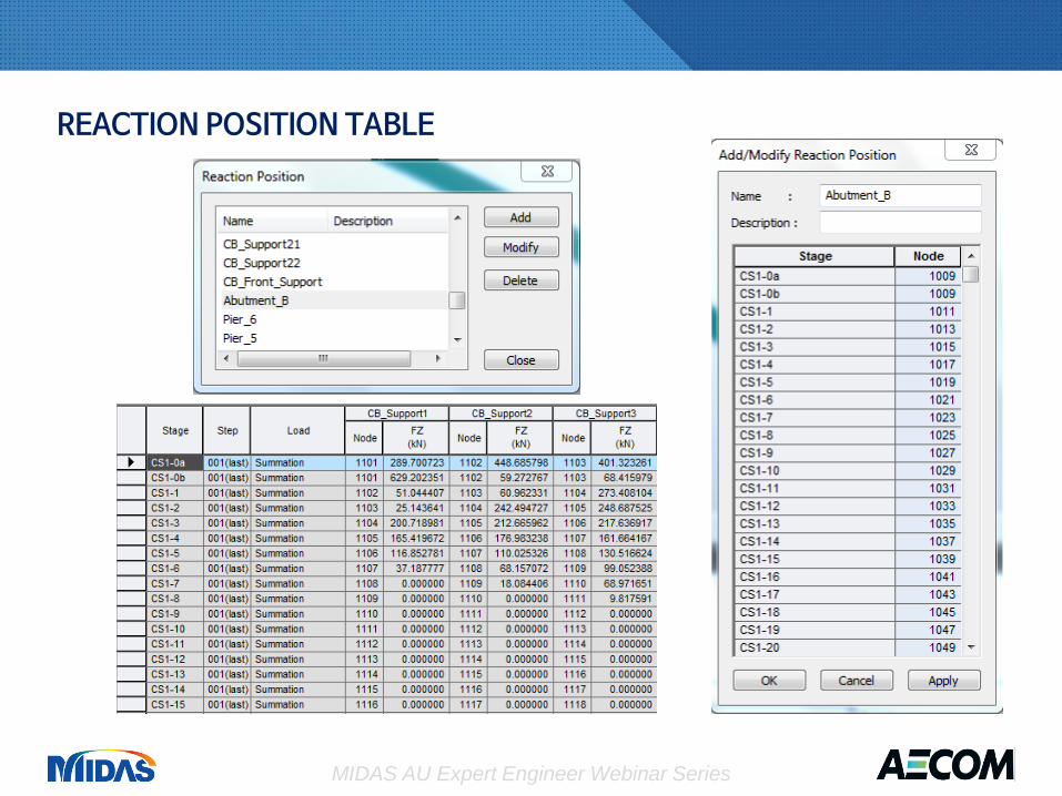
REACTION POSITION TABLE
MIDAS AU Expert Engineer Webinar Series
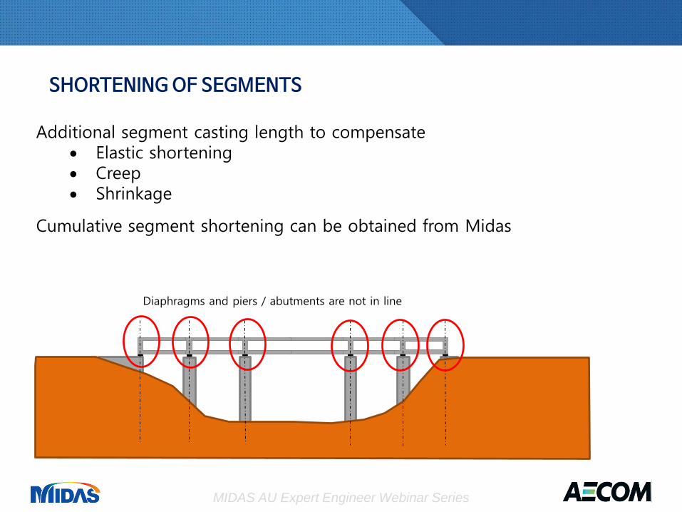
Additional segment casting length to compensate• Elastic shortening• Creep• Shrinkage
Cumulative segment shortening can be obtained from Midas
Diaphragms and piers / abutments are not in line
SHORTENING OF SEGMENTS

MIDAS AU Expert Engineer Webinar Series
Transient Effects• Road traffic (Influence line analysis)• Thermal effects (Beam section temperature)• Wind• Differential Settlement• Bearing replacement
Design envelopes and co-existing actions can be conveniently obtainedfrom Midas
IN-SERVICE STAGE ANALYSIS

MIDAS AU Expert Engineer Webinar Series
• SLS Bending Stress at Tendon level for Exposure B2, C1, C2, U(AS5100.5 Clause 8.6.2.3)
• SLS Stress Increment Check (AS5100.5 Clause 8.6.2.1(b)• ULS Bending Moment Capacity (AS5100.5 Clause 8.1)• ULS Shear and Torsion Capacity (AS5100.5 Clause 8.2)
Note the requirement of VicRoads BTN025• Transverse Analysis• ULS Longitudinal Shear at CJ and Web / Flange Interface
(AS5100.5 Clause 8.4)
SECTION CAPACITY CHECK TO AS5100

MIDAS AU Expert Engineer Webinar Series
Internal Prestress External Prestress
Larger eccentricity Max length about 300m
Higher strength at ultimate Lower immediate prestress loss
Efficient tendon profile Easier installation
Max length about 150m More expensive hardware
More complicated segmentconstruction
Provision for future replacement
CONTINUITY PRESTRESS

MIDAS AU Expert Engineer Webinar Series
• Deflection of bridge can be output from Midas• AS5100.2 Clause 7.11 requires no sag deflection under permanent loads• Self weight will create sag deflection• An incrementally launched bridge cannot be pre-cambered• Uneconomical to eliminate sag deflection by continuity prestress • Assess the effect of net sag deflections of the bridge for
• visual impact• required clearance underneath the bridge• bridge deck drainage• loading (e.g. extra surfacing thickness)
• Dispensation from the asset owner
PERMANENT LOAD DEFLECTION