MICROWAVE OVEN SERVICE MANUAL - SEM Boutique
32
MICROWAVE OVEN SERVICE MANUAL MODEL: MS-2324F CAUTION BEFORE SERVICING THE UNIT,READ THE SAFETY PRECAUTIONS IN THIS MANUAL. Website http://biz.lgservice.com P/NO : 3828W5S3766 April, 2004 Printed in Korea
Transcript of MICROWAVE OVEN SERVICE MANUAL - SEM Boutique

MICROWAVE OVENSERVICE MANUALMODEL: MS-2324FCAUTIONBEFORE SERVICING THE UNIT,READ THE SAFETY PRECAUTIONS IN THIS MANUAL.
Website http://biz.lgservice.com
P/NO : 3828W5S3766April, 2004
Printed in Korea

This device is to be serviced only by properly qualified service personnel.Consult the service manual for proper service procedures to assure continued safety operation and for precautions to betaken to avoid possible exposure to excessive microwave energy.
PRECAUTIONS TO BE OBSERVED BEFORE ANDDURING SERVICING TO AVOID POSSIBLEEXPOSURE TO EXCESSIVE MICROWAVE ENERGYA) Do not operate or allow the oven to be operated with the door open.
B) Make the following safety checks on all ovens to be serviced before activating the magnetron or other
microwave source, and make repairs as necessary; (1) interlock operation, (2) proper door closing, (3)
seal and sealing surfaces (arcing, wear, and other damage), (4) damage to or loosening of hinges and
latches, (5) evidence of dropping or abuse.
C) Before turning on microwave power for any service test or inspection within the microwave generating
compartments, check the magnetron, wave guide or transmission line, and cavity for proper alignment,
integrity, and connections.
D) Any defective or misadjusted components in the interlock, monitor, door seal, and microwave generation
and transmission systems shall be repaired, replaced, or adjusted by procedures described in this manual
before the oven is released to the owner.
E) A microwave leakage check to verify compliance with the Federal Performance Standard should be
performed on each oven prior to release to the owner.
SAFETY PRECAUTIONS
CAUTIONMICROWAVE RADIATION
DO NOT BECOME EXPOSED TO RADIATION FROM THE MICROWAVE GENERATOROR OTHER PARTS CONDUCTING MICROWAVE ENERGY.

CONTENTS(Page)
SAFETY PRECAUTIONS - - - - - - - - - - - - - - - - - - - - - - - - - - - - - - - - - - - - - - - - - - - - - - - - - - - - - - - - - - - - - - - - - - - - - Inside front cover
SPECIFICATIONS - - - - - - - - - - - - - - - - - - - - - - - - - - - - - - - - - - - - - - - - - - - - - - - - - - - - - - - - - - - - - - - - - - - - - - - - - - - - - - - - - - - - - - - - - - - - - - - - - - - - - 1-1
CAUTIONS - - - - - - - - - - - - - - - - - - - - - - - - - - - - - - - - - - - - - - - - - - - - - - - - - - - - - - - - - - - - - - - - - - - - - - - - - - - - - - - - - - - - - - - - - - - - - - - - - - - - - - - - - - - - - - 2-1
INSTALLATIONS - - - - - - - - - - - - - - - - - - - - - - - - - - - - - - - - - - - - - - - - - - - - - - - - - - - - - - - - - - - - - - - - - - - - - - - - - - - - - - - - - - - - - - - - - - - - - - - - - - - - - - 3-1
OPERATING INSTRUCTIONS - - - - - - - - - - - - - - - - - - - - - - - - - - - - - - - - - - - - - - - - - - - - - - - - - - - - - - - - - - - - - - - - - - - - - - - - - - - - - - - - - - - - 4-1
FEATURES - - - - - - - - - - - - - - - - - - - - - - - - - - - - - - - - - - - - - - - - - - - - - - - - - - - - - - - - - - - - - - - - - - - - - - - - - - - - - - - - - - - - - - - - - - - - - - - - - - - - - - - - - - - - - - - - - - - - - - - 4-1
CONTROL PANEL - - - - - - - - - - - - - - - - - - - - - - - - - - - - - - - - - - - - - - - - - - - - - - - - - - - - - - - - - - - - - - - - - - - - - - - - - - - - - - - - - - - - - - - - - - - - - - - - - - - - - - - - - - - - - 4-1
OPERATING SEQUENCE - - - - - - - - - - - - - - - - - - - - - - - - - - - - - - - - - - - - - - - - - - - - - - - - - - - - - - - - - - - - - - - - - - - - - - - - - - - - - - - - - - - - - - - - - - - - - - - - - - - 4-2
SCHEMATIC DIAGRAM - - - - - - - - - - - - - - - - - - - - - - - - - - - - - - - - - - - - - - - - - - - - - - - - - - - - - - - - - - - - - - - - - - - - - - - - - - - - - - - - - - - - - - - - - - - - - - - - - - - - - - 4-3
CIRCUIT DESCRIPTION - - - - - - - - - - - - - - - - - - - - - - - - - - - - - - - - - - - - - - - - - - - - - - - - - - - - - - - - - - - - - - - - - - - - - - - - - - - - - - - - - - - - - - - - - - - - - - - - - - - - - 4-4
SERVICE INFORMATION - - - - - - - - - - - - - - - - - - - - - - - - - - - - - - - - - - - - - - - - - - - - - - - - - - - - - - - - - - - - - - - - - - - - - - - - - - - - - - - - - - - - - - - - - - 5-1
TOOLS AND MEASURING INSTRUMENTS - - - - - - - - - - - - - - - - - - - - - - - - - - - - - - - - - - - - - - - - - - - - - - - - - - - - - - - - - - - - - - - - - - - - - - - - - - 5-1
MICROWAVE LEAKAGE TEST - - - - - - - - - - - - - - - - - - - - - - - - - - - - - - - - - - - - - - - - - - - - - - - - - - - - - - - - - - - - - - - - - - - - - - - - - - - - - - - - - - - - - - - - - - - - 5-1
MEASUREMENT OF MICROWAVE POWER OUTPUT - - - - - - - - - - - - - - - - - - - - - - - - - - - - - - - - - - - - - - - - - - - - - - - - - - - - - - - - - - - 5-3
DISASSEMBLY AND ADJUSTMENT - - - - - - - - - - - - - - - - - - - - - - - - - - - - - - - - - - - - - - - - - - - - - - - - - - - - - - - - - - - - - - - - - - - - - - - - - - - - - - - - - - - - 5-3
INTERLOCK CONTINUITY TEST - - - - - - - - - - - - - - - - - - - - - - - - - - - - - - - - - - - - - - - - - - - - - - - - - - - - - - - - - - - - - - - - - - - - - - - - - - - - - - - - - - - - - - - - - 5-7
COMPONENT TEST PROCEDURE - - - - - - - - - - - - - - - - - - - - - - - - - - - - - - - - - - - - - - - - - - - - - - - - - - - - - - - - - - - - - - - - - - - - - - - - - - - - - - - - - - - - - - 5-8
TROUBLE SHOOTING - - - - - - - - - - - - - - - - - - - - - - - - - - - - - - - - - - - - - - - - - - - - - - - - - - - - - - - - - - - - - - - - - - - - - - - - - - - - - - - - - - - - - - - - - - - - - - - - - - - - - 5-12
EXPLODED VIEW - - - - - - - - - - - - - - - - - - - - - - - - - - - - - - - - - - - - - - - - - - - - - - - - - - - - - - - - - - - - - - - - - - - - - - - - - - - - - - - - - - - - - - - - - - - - - - - - - - - - - 6-1
REPLACEMENT PARTS LIST - - - - - - - - - - - - - - - - - - - - - - - - - - - - - - - - - - - - - - - - - - - - - - - - - - - - - - - - - - - - - - - - - - - - - - - - - - - - - - - - - - - - 7-1

SPECIFICATIONS
1-1
This microwave oven is designed for household use only.
It is not recommended for commercial purposes.
DESCRIPTION
MS-2324F
230 Volts AC 50 Hz
1,250 Watts
Single phase, 3 wire grounded
850 Watts full microwave power (IEC60705)
2,450 MHz
2M167B - M47J1
0 ~ 60 min.
507 (W) x 283 (H) x 418 (D) mm
331 (W) x 203 (H) x 360 (D) mm
14.0 kg (approx.)
16.0 kg (approx.)
Microwave Power for Variable Cooking
Power level
Max
620W
380W
cDefrost
90W
Owner's manual
Glass turntable
Roller Rest
ITEM
MODEL
Power Requirement
Power Output
Microwave Frequency
Magnetron
Timer
Outside Dimensions
Cavity Dimensions
Net Weight
Shipping weight
Control Complement
Nameplate Location
Accessories
Back Side

• DO NOT operate on a 2-wire extension cord duringrepair and use.
• NEVER TOUCH any oven components or wiring duringoperation.
• BEFORE TOUCHING any parts of the oven, alwaysremove the power plug from the outlet.
• For about 30 seconds after the oven stop, an electriccharge remains in the high voltage capacitor. Whenreplacing or checking, you must discharge the highvoltage capacitor by shorting across the two terminalswith an insulated screwdriver.
• Remove your watches whenever working close to orreplacing the Magnetron.
• DO NOT touch any parts of the control panel circuit. Aresulting static electric discharge may damage thisP.C.B.
• NEVER operate the oven with no load.• NEVER injure the door seal and front plate of the oven
cavity.• NEVER put iron tools on the magnetron.• NEVER put anything into the latch hole and the
interlock switches area.
• Proper operation of the microwave oven requiresthat the magnetron be assembled to the waveguideand cavity. Never operate the magnetron unless it isproperly installed.
• Be sure that the magnetron gasket is properlyinstalled around the dome of the tube wheneverinstalling the magnetron.
2-1
CAUTIONS
Unlike other appliances, the microwave oven ishigh-voltage and high-current equipment.Though it is free from danger in ordinary use,extreme care should be taken during repair.
THE OVEN IS TO BE SERVICED ONLYBY PROPERLY QUALIFIED SERVICEPERSONNEL.
MICROWAVE RADIATIONPersonnel should not be exposed to themicrowave energy which may radiate from themagnetron or other microwave generatingdevice if it is improperly used or connection.All input and output microwave connections,waveguide, flange and gasket must be securenever operate the device without a microwaveenergy absorbing load attached.Never look into an open waveguide or antennawhile the device is energized.
GasketANTENNA
COOLING FIN
MAGNETRONCHASSIS GROUND
FILAMENTTERMINALS
MAGNETRON

3-1
INSTALLATIONS
INSTALLING1. Empty the microwave oven and clean inside it with
a soft, damp cloth. Check for damage such asmisaligned door, damage around the door or dentsinside the cavity or on the exterior.
2. Put the oven on a counter, table, or shelf that isstrong enough to hold the oven and the food andutensils you put in it. (The control panel side of theoven is the heavy side. Use care when handling.)
3. Do not block the vent and the air intake openings.Blocking vent or air intake openings can causedamage to the oven and poor cooking results.Make sure the microwave oven legs are in place toensure proper air flow.
4. The oven should not be installed in any area whereheat and steam are generated, because they maydamage the electronic or mechanical parts of theunit.Do not install the oven next to a conventionalsurface unit or above a conventional wall oven.
5. Use microwave oven in an ambient temperatureless than 104°F(40°C).
6. Place the microwave oven on a sturdy and flatsurface at least 10 cm(4 inches) from the wall.
7. Place the microwave oven as far away as possiblefrom TV, RADIO, COMPUTER, etc., to preventinterference.
EARTHING INSTRUCTIONSThis microwave oven is designed to be used in a fullyearthed condition.It is imperative, therefore, to make sure it is properlyearthed before servicing
WARNING-THIS APPLIANCEMUST BE EARTHED
IMPORTANT
As the colors of the wires in the mains lead of thisappliance may not correspond with the coloredmarkings identifying the terminals in your plug,proceed as follows.
The wire which is colored green-and-yellow must beconnected to the terminal in the plug which is markedwith the letter E or by the earth symbol ( ) orcolored green or green-and-yellow.
The wire which is colored blue must be connected tothe terminal in the plug which is marked with the letterN or colored black.
The wire which is colored brown must be connectedto the terminal in the plug which is marked with theletter L or colored red.
BEFORE YOU BEGIN, READ THE FOLLOWING INSTRUCTIONS COMPLETELY AND CAREFULLY.
10cm
The wires in this mains lead are colored inaccordance with the following code:
Green-and-yellow: EarthBlue: NeutralBrown: Live

FEATURES
CONTROL PANEL
4-1
OPERATING INSTRUCTIONS
Glass Tray
Roller Rest
Oven Front Plate
Door Seal
Control Panel
Safety Door Lock System
Window Door Screen
1
22
1. POWER CONTROL KNOB: Used in selected the desired power level for cooking.
2. TIMER KNOB: Used to set the cooking time.

4-2
OPERATING SEQUENCE
MICROWAVE COOKING1. Open the oven door, place the food on the turntable
in the oven, and close the oven door.
2. Set the microwave power selector to the desiredpower level. There are five power levels from 90Wto MAX. The power selector can be set to any oneof these positions.
3. Set the timer to the desired cooking time. Theturntable begins to rotate and cooking starts. At theend of cooking time you will a single ring sound,and the lamp is turn off.
NOTE:• Each number represents minutes. To ensure
accurate timing, it is advisable to turn the timer knobslightly passed the desired cooking time and thenback to the proposed setting.
• Press the door opener to check the cookingcondition during oven operation. Opening the doorduring oven operation automatically turns off theoven and stops the timer. If cooking is to continue,close the door. Cooking will be resumed until the fullcooking time has elapsed.
POSITIONSMax
620W380WcDefrost
90W

SCHEMATIC DIAGRAM
4-3
SC
HE
MA
TIC
DIA
GR
AM
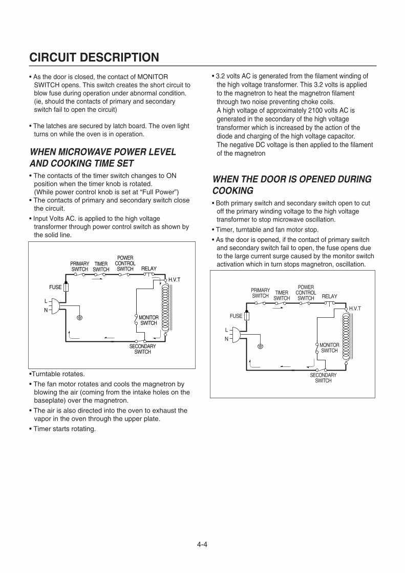
CIRCUIT DESCRIPTION• As the door is closed, the contact of MONITOR
SWITCH opens. This switch creates the short circuit toblow fuse during operation under abnormal condition.(ie, should the contacts of primary and secondaryswitch fail to open the circuit)
• The latches are secured by latch board. The oven lightturns on while the oven is in operation.
WHEN MICROWAVE POWER LEVELAND COOKING TIME SET• The contacts of the timer switch changes to ON
position when the timer knob is rotated. (While power control knob is set at “Full Power”)
• The contacts of primary and secondary switch closethe circuit.
• Input Volts AC. is applied to the high voltagetransformer through power control switch as shown bythe solid line.
•Turntable rotates.
• The fan motor rotates and cools the magnetron byblowing the air (coming from the intake holes on thebaseplate) over the magnetron.
• The air is also directed into the oven to exhaust thevapor in the oven through the upper plate.
• Timer starts rotating.
• 3.2 volts AC is generated from the filament winding ofthe high voltage transformer. This 3.2 volts is appliedto the magnetron to heat the magnetron filamentthrough two noise preventing choke coils. A high voltage of approximately 2100 volts AC isgenerated in the secondary of the high voltagetransformer which is increased by the action of thediode and charging of the high voltage capacitor.The negative DC voltage is then applied to the filamentof the magnetron
WHEN THE DOOR IS OPENED DURINGCOOKING• Both primary switch and secondary switch open to cut
off the primary winding voltage to the high voltagetransformer to stop microwave oscillation.
• Timer, turntable and fan motor stop.
• As the door is opened, if the contact of primary switchand secondary switch fail to open, the fuse opens dueto the large current surge caused by the monitor switchactivation which in turn stops magnetron, oscillation.
4-4
FUSE
PRIMARYSWITCH
SECONDARYSWITCH
MONITORSWITCH
L
N
H.V.T
RELAYTIMER
SWITCH
POWERCONTROLSWITCH
FUSE
PRIMARYSWITCH
SECONDARYSWITCH
L
N
H.V.T
RELAYTIMER
SWITCH
POWERCONTROLSWITCH
MONITORSWITCH

NECESSARY TOOLSTools normally used for TV servicing are sufficient.
Standard tools are listed below.
• Diagonal pliers• Long nose pliers• Phillips screwdriver• Flat blade screwdriver• Wrench (size 5mm)• Nutdriver (size 5mm)• Adjustable wrench• Soldering iron• Solder• Vinyl insulation tape• Polishing cloth
CAUTIONS• Be sure to check microwave leakage prior to
servicing the oven if the oven is operative prior toservicing.
• The service personnel should inform themanufacture importer, or assembler of any certifiedoven unit found to have a microwave emissionlevel in excess of 5 mW/cm2 and should repair anyunit found to have excessive emission levels at no costto the owner and should ascertain the cause of theexcessive leakage. The service personnel shouldinstruct the owner not to use the unit until the oven hasbeen brought into compliance.
• If the oven operates with the door open, the servicepersonnel should:-Tell the user not to operate the oven.-Contact the manufacturer.
• The service personnel should check all surface andvent openings for microwave leakage.
• Check for microwave leakage after every servicing. Thepower density of the microwave radiation leakageemitted by the microwave oven should not exceed 5 mW/cm2. Always start measuring of an unknown fieldto assure safety for operating personnel from radiationleakage.
NECESSARY MEASURING INSTRUMENTS• TESTER (VOLTS-DC, AC., Ohmmeter)• Microwave survey meter- Holaday HI-1500
HI-1501- Narda 8100
8200• Inch scale• 600 cc non conductive material beaker (glass or
plastic), inside diameter: approx. 8.5 cm(31/2 in.)• Cylindrical and made of borosilicate glass vessel.
max. thickness: 3 mmoutside diameter: approx. 190mmheight: approx. 90mm
• Glass thermometer: 100°C or 212°F (1 deg scale)
MEASURING MICROWAVE ENERGYLEAKAGE• Pour 275±15 cc of 20±5°C(68±9°F) water in a beaker
which is graduated to 600 cc, and place the beakeron the center of the turntable.
• Set the energy leakage monitor to 2,450 MHz anduse it following the manufacturer's recommendedtest procedure to assure correct result.
• When measuring the leakage, always use the 2-inch(5 cm) spacer supplied with the probe.
• Operate the oven at its maximum output.• Measure the microwave radiation using and
electromagnetic radiation monitor by holding theprobe perpendicular to the surface being measured
Move probe along shaded area
Probe scanning speedLess than 2.5 cm/sec(1 in/sec)
5-1
SERVICE INFORMATIONTOOLS AND MEASURING INSTRUMENTS
MICROWAVE LEAKAGE TEST

MEASUREMENT WITH OUTER CASEREMOVED• When you replace the magnetron, measure for
microwave energy leakage before the outer case isinstalled and after all necessary components arereplaced or adjusted.Special care should be taken in measuring thefollowing parts. (Circled area of below Fig.)- Around the magnetron- The waveguide
MEASUREMENT WITH A FULLYASSEMBLED OVEN• After all components, including the outer case, are fully
assembled, measure for microwave energy leakagearound the door viewing window, the exhaust opening,and air inlet openings.
• Microwave energy leakage must not exceed the valuesprescribed below.
NOTE : Leakage with the outer case removedless than5 mW/cm.sq. Leakage for a fully assembledoven (Before the latch switch (primary) isinterrupted) with the door in a slightly openedposition-less than 2 mW/cm.sq.
NOTES WHEN MEASURING• Do not exceed meter full scale deflection.• The test probe must be removed no faster than
1 inch/sec (2.5 cm/sec) along the shaded area,otherwise a false reading may result.
• The test probe must be held with the grip portion of thehandle.A false reading may result if the operator's hand isbefween the handle and the probe.
• When testing near a corner of the door, keep the probeperpendicular to the surface making sure the probehorizontally along the oven surface, this may possiblycause probe damage.
RECORD KEEPING AND NOTIFICATIONAFTER MEASUREMENT• After adjustment and repair of any microwave energy
interruption or microwave energy blocking device,record the measured values for future reference. Alsoenter the information on the service invoice.
• The microwave energy leakage should not be morethan 4 mW/cm.sq. after determining that all parts are ingood condition, functioning properly and genuinereplacement parts which are listed in this manual havebeen used.
• At least once a year, have the electromagnetic energyleakage monitor checked for calibration by itsmanufacturer.
5-2
WARNING : AVOID CONTACTING ANYHIGH VOLTAGE PARTS
(Magnetron, H.V. Transformer,H.V. Capacitor, H.V. Cable Ass’y,H.V. Circuit Protector)

• Microwave power output measurement is made withthe microwave oven supplied at its rated voltage andoperated at its maximum microwave power setting witha load of (1000±5) g of potable water.
• The water is contained in a cylindrical borosilicate glassvessel having a maximum material thickness of 3 mmand an outside diameter of approximately 190mm.
• The oven and the empty vessel are at ambienttemperature prior to the start of the test.
• The initial temperature (±1) of the water is (10±2)°C. Itis measured immediately before the water is added tothe vessel. After addition of the water to the vessel,the load is immediately placed on the center of theturntable which is in thd lowest position and themicrowave power switched on.
• The time T for the temperature of the water to rise by avalue ∆ T of (10±2)°K is measured, where T is the timein seconds and ∆T is the temperature rise. The initialand final water temperatures are selected so that themaximum difference between the final watertemperature and the ambient temperature is 5°K.
• The microwave power output P in watts is calculatedfrom the following formula :
4187 x (∆T)
T
is measured while the microwave generator isoperating at full power. Magnetron filament heat-uptime is not included. (about 3 sec)
• The water is stirred to equalize temperature throughoutthe vessel, prior to measuring the final watertemperature.
• Stirring devices and measuring instruments areselected in order to minimize addition or removal ofheat.
A. OUTER CASE REMOVAL
1) Disconnect the power supply cord from the outlet.2) Remove the screws from the rear and along side
edges of the case. The outer case must be moved backward to be liftedoff.
B. POWER SUPPLY CORD1) Remove the outer case.2) Disconnect two terminals, and remove one screw of
the earth terminal.
CAUTION: DISCHARGE THE HIGH VOLTAGE CAPACITOR BEFORE SERVICING(refer to page 2-1)
C. CONTROL PANEL ASSEMBLY1) Disconnect the leadwire from the Timer motor2) Remove the screws for securing the control panel.3) Lift control panel ASS ’Y from the oven by the tab
unhooked.
5-3
WATER LOAD
TURNTABLE
MEASUREMENT OF MICROWAVE POWER OUTPUT
DISASSEMBLY AND ADJUSTMENT
P =

D. DOOR GROSS ASSEMBLY REMOVAL1) Open the door.2) Remove the choke cover cap very carefully with a
flat-blade screwdriver.CAUTION : Be careful not to damage door seal plate
by screwdriver.3) Lift up and push the door.
NOTE:1. After replacing the door, be sure to check that the
primary switch, monitor switch, and secondary switchoperate normally.
2. After replacing the door, check for microwave energyleakage with a survey meter. Microwave energy mustbe below the limit of 5 mW/cm. (with a 275 ml waterload)
3. When mounting the door assembly to the ovenassembly, be sure to adjust the door assembly parallelto the chassis. Also adjust so the door has no playbetween the inner door surface and oven frameassembly. If the door assembly is not mountedproperly, microwaves may leak from the clearancebetween the door and the oven.
E. HIGH VOLTAGE TRANSFORMERREMOVAL
1) Discharge the high voltage capacitor.2) Disconnect the leadwire from magnetron, high voltage
transformer, and capacitor.3) Remove the screw holding the high voltage
transformer to the baseplate.
F. FAN MOTOR ASSEMBLY REMOVAL1) Discharge the high voltage capacitor.2) Disconnect the leadwire from fan motor, noise filter
and high voltage capacitor.3) Remove the two screws holding the the suction guide
ASS’Y to the oven cavity and remove the high voltagediode earth screw.
4) Remove the screw of the capacitor bracket.5) Remove the two screws holding the fan motor ASS’Y
to the suction guide ASS’Y.
G. HIGH VOLTAGE CAPACITOR ANDDIODE REMOVAL
1) Discharge the high voltage capacitor.2) Disconnect the leadwire from fan motor, noise filter
and high voltage capacitor.3) Remove the screw holding the suction guide ASS’Y to
the oven cavity and remove the high voltage diodeearth screw.
4) Remove the screw holding the high voltage capacitorbracket.
5-4
Remove Hinge Plate
Remove Door Assembly
H.VTransformer
SuctionGuide
Fan Motor ASS Y
H.VCapacitor
H.V.Diode

H. AIR DUCT ASSEMBLY REMOVAL1) Disconnect the leadwire from lamp, A.C Relay and
monitor resistor.2) Remove the mounting screw to the magnetron.
I. MAGNETRON REMOVAL1) Disconnect the leadwire from the high voltage
transformer and high voltage capacitor.2) Carefully remove the mounting screws holding the
magnetron and the waveguide.3) Remove the magnetron ASS’Y until the tube is
clear from the waveguide.
NOTE:1. When removing the magnetron, make sure its
dome does not hit any adjacent parts, or it may bedamaged.
2. When replacing the magnetron, be sure to installthe magnetron gasket in the correct position andbe sure that the gasket is in good condition.
3. After replacing the magnetron, check for microwaveleakage with a survey meter around themagnetron. Microwave energy must be below thelimit of 5 mW/cm2. (With a 275 ml. water load).Make sure that gasket is rigidly attached to themagnetron. To prevent microwave leakage,tighten the mounting screws properly, making surethere is no gap between the waveguide and themagnetron.
J. REMOVING THE TURNTABLE MOTOR1) Remove the turntable.2) Remove the turntable shaft VERY CAREFULLY.3) Lay the unit down on its back.4) Remove the turntable motor cover.
The turntable base cover is easily removed bypinching the six parts with a wire cutting.
5) Disconnect the leadwire from the turntable motorterminals.
6) Remove the screw securing the turntable motor tothe oven cavity ASS’Y
7) After repairing the motor, rotate the removedturntable motor cover.
8) Fit the turntable motor cover’s projecting part to thebase plate slit.
NOTE:1. Remove the wire lead from the turntable motor
VERY CAREFULLY.2. Be sure to grasp the connector, not the wires, when
removing.
5-5
Waveguide
MagnetronGasketMagnetron
Dome
Waveguide Bracket
Magnetron
Wire Leads
Turntable Motor

K. TIMER MOTOR REMOVAL1) Remove the control panel assembly from the
cavity.2) Remove screws which hold the timer motor to the
control panel.3) Remove the timer motor from the control panel. 4) Remove the power control knob and the timer
knob.
L. INTERLOCK SYSTEM1) INTERLOCK MECHANISM
The door lock mechanism is a device which hasbeen specially designed to eliminate completelymicrowave activity when the door is opened duringcooking and thus to prevent the danger resultingfrom the microwave leakage.
2) MOUNTING OF THE PRIMARY/MONITOR/SECONDARY SWITCHES TO THE LATCHBOARD
3) INSTALLATION AND ADJUSTMENT OF THELATCH BOARD TO THE OVEN ASSEMBLY
• Mount the latch board to the oven assembly.• Adjust the latch board in the arrow direction so that
oven door will not have any play in it when the dooris closed.
• Tighten the mounting screw.• Check for play in the door by pushing the door
release button.Door movement should be lessthan 0.5 mm.(1/64 inch)Don't push the door release button while makingadjustment. Make sure that the latch movessmoothly after adjustment are completed and thatthe screws are tight. Make sure the primary, monitor, and secondary switches operate properly byfollowing the continuity test procedure.
5-6
PRIMARYSWITCH
ADJUSTMENTDIRECTION
MONITORSWITCH
SECONDARYSWITCH
CAUTION: CHECK THE CORRECT POSITION
MAGNETRON
H.V. TRANSFORMER
PRIMARY CIRCUIT PROTECTOR
H.V. CAPACITOR
H.V.DIODE
FIG. 1

COMNO
COM
NC
COM NO
A. PRIMARY INTERLOCK SWITCH TESTWhen the door release button is depressed slowlywith the door closed, an audible click should beheard at the same time or successively atintervals. When the button is released slowly, thelatches should activate the switches with anaudible click.If the latches do not activate the switches whenthe door is closed, the switches should be aadjusted in accordance with the adjustmentprocedure. Disconnect the wire lead from theprimary switch. Connect the ohmmeter leads tothe common (COM) and normally open (NO)terminal of the switch. The meter should indicatean open circuit in the door open condition.When the door is closed, the meter shouldindicate a closed circuit. When the primary switch operation is abnormal,make the necessary adjustment or replace theswitch only with the same type of switch.
B. SECONDARY INTERLOCK SWITCH TESTDisconnect the wire lead from the secondaryswitch. Connect the ohmmeter leads to the common(COM) and normally open (NO) terminals of theswitch. The meter should indicate a open circuit inthe door open condition. When the door is closed,meter should indicate an closed circuit. When thesecondary switch operation is abnormal, make thenecessary adjustment or replace the switch onlywith the same type of switch.
C. MONITOR SWITCH TESTDisconnect the wire lead from the monitor switch.Connect the ohmmeter leads to the common(COM) and normally closed (NC) terminals of theswitch. The meter should indicate closed circuit inthe door open condition. When the door is closed,meter should indicate an open circuit. When themonitor switch operation is abnormal, replace withthe same type of switch.NOTE: After repairing the door or the interlocksystem, it is necessary to do this continuity test before operating the oven.
5-7
INTERLOCK CONTINUITY TEST
WARNING : FOR CONTINUED PROTECTION AGAINST EXCESSIVE RADIATIONEMISSION,REPLACE ONLY WITH IDENTICAL REPLACEMENT PARTS.
TYPE NO.SZM-V 16-FA-63 OR VP-533A-OF FOR PRIMARY SWITCHTYPE NO.SZM-V 16-FA-62 OR VP-532A-OF FOR MONITOR SWITCHTYPE NO.SZM-V 16-FA-63 OR VP-533A-OF FOR SECONDARY SWITCH
COMPONENTS TEST PROCEDURE RESULTSSWITCHES Check for continuity of the Door Door(Wire leads removed) switch with an Ohm-meter open closed
PrimarySwitch
MonitorSwitch
SecondarySwitch
NOTE : After checking for the continuity of switches, make sure that areconnected correctly.

5-8
COMPONENT TEST PROCEDURE
CAUTIONS1. DISCONNECT THE POWER SUPPLY CORD FROM THE OUTLET WHENEVER REMOVING THE
OUTER CASE FROM THE UNIT. PROCEED WITH THE TEST ONLY AFTER DISCHARGING THE HIGHVOLTAGE CAPACITOR AND REMOVING THE WIRE LEADS FROM THE PRIMARY WINDING OF THEHIGH VOLTAGE TRANSFORMER. (SEE PAGE 2-1)
2. ALL OPERATIONAL CHECKS WITH MICROWAVE ENERGY MUST BE DONE WITH A LOAD (1 LITEROF WATER IN CONTAINER) IN THE OVEN.
HIGH VOLTAGETRANSFORMER(Wire leads removed)
MAGNETRON(Wire leads removed)
Approx.: 1.4 ohmApprox.: 90 ohmLess than: 1 ohm
Normal: InfiniteNormal: Infinite
Normal: Less than 1 ohm
Normal: Infinite
PRIMARY TERMINAL
SECONDARY TERMINAL
WINDINGFILAMENT
TERMINAL
COMPONENTS TEST PROCEDURE RESULTS
1. Measure the resistance.(Ohm-meter scale: Rx1)• Primary winding• Secondary winding• Filament winding
2. Measure the resistance.(Ohm-meter scale: Rx1000)• Primary winding to ground• Filament winding to ground
1. Measure the resistance.(Ohm-meter scale: Rx1)• Filament terminal
2. Measure the resistance.(Ohm-meter scale: Rx1000)• Filament to chassis
5-9
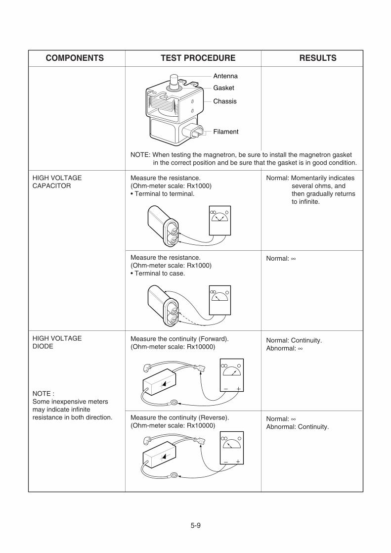
NOTE: When testing the magnetron, be sure to install the magnetron gasketin the correct position and be sure that the gasket is in good condition.
Antenna
Gasket
Chassis
Filament
HIGH VOLTAGECAPACITOR
Measure the resistance.(Ohm-meter scale: Rx1000)• Terminal to terminal.
Normal: Momentarily indicatesseveral ohms, andthen gradually returnsto infinite.
Normal: ∞
Normal: ∞Abnormal: Continuity.
Normal: Continuity.Abnormal: ∞
Measure the resistance.(Ohm-meter scale: Rx1000)• Terminal to case.
Measure the continuity (Forward).(Ohm-meter scale: Rx10000)
Measure the continuity (Reverse).(Ohm-meter scale: Rx10000)
HIGH VOLTAGEDIODE
NOTE :Some inexpensive metersmay indicate infiniteresistance in both direction.
COMPONENTS TEST PROCEDURE RESULTS

5-10
COMPONENTS TEST PROCEDURE RESULTSMAIN FUSE Check for continuity of the fuse with an
multi-meter.
NOTE: If the fuse is blown, check the primary, the secondary, and the monitorswitches, H.V.D. and H.V.C. before replacing the fuse.If the fuse is blown by improper switch operation replace the defective switchand the fuse at the same time. Replace just the fuse if the switches operatenormally.
Normal Abnormal

5-11
COMPONENTS TEST PROCEDURE RESULTS
TIMER MOTOR(Wire leads removed)
FAN MOTOR(Wire leads removed)
TURNTABLEMOTOR(Wire leads removed)
Measure the resistance.(Ohm-meter scale: R x 100)
Measure the resistance.(Ohm-meter scale: R x 1000)
Normal:
Abnormal: or several
Normal: Approx. 100~200Abnormal: or several
Note: A is ON,OFF switch B ispower supply terminal of thetimer motor C is defrost switch
NOTE : • A MICROWAVE LEAKAGE TEST MUST ALWAYS BE PERFORMED WHEN THE UNIT ISSERVICED FOR ANY REASON.
• MAKE SURE THE WIRE LEADS ARE IN THE CORRECT POSITION.• WHEN REMOVING THE WIRE LEADS FROM THE PARTS, BE SURE TO GRASP THE
CONNECTOR, NOT THE WIRES.
A ~ B A ~ C
30 ~ 50 300 ~ 500
Turn on
A
B Approx. 25 K
Turn Off
A
B
Microwave Switch
AB
C

5-12
CONDITION
Microwave ovendoes not work.
Inserting many plug into oneplug outlet and usingthem at the same time(causes overloading).
Microwave oven plug is notinserted tightly.
Output power is too low. Low AC input voltage.
Food temperature is too low.
Using metallic ware andallowing it to touch the ovenwall.
Sparks occur.
Inconsistent intensity ofmicrowave by theircharacteristics.
1. Use plastic wrap or lid.2. Stir once or twice while
cooking soup, cocoa ormilk, etc.
Uneven cooking.
Ceramic ware trimmed ingold or silver powder is used.
Avoid using other electricalappliances when you use themicrowave oven.
Insert microwave oven plugsecurely.
Use the microwave oven atadequate line voltage.
This may not be a defect.It is possible that the foodshould be cooked for alonger time period.
Do not use metallic ware forcooking except where notedin the cooking guide.
Do not use any type ofcookware with metallictrimming.
CAUSE REMEDY
Excessive weight on tray orimproperly balanced.
Distribute food evenly. Cooksmaller portions and, or uselighter weight cookware.
Turntable drags or makesnoise.
TROUBLE SHOOTING
CAUTIONS1. Check grounding before checking for trouble.2. Be careful of the high voltage circuit.3. Discharge the high voltage capacitor. (See page 2-1)4. When checking the continuity of the switches or of the high voltage transformer, disconnect one lead wire
from these parts and then check continuity with the AC plug removed. To do otherwise may result in afalse reading or damage to your meter.
WHEN YOU GET A COMPLAINT FROM YOUR CUSTOMER, EVALUATE THE COMPLAINT CAREFULLY. IF
THE FOLLOWING SYMPTOMS APPLY, PLEASE INSTRUCT THE CUSTOMER IN THE PROPER USE OF THE
MICROWAVE OVEN. THIS CAN ELIMINATE AN UNNECESSARY SERVICE CALL.
5-13
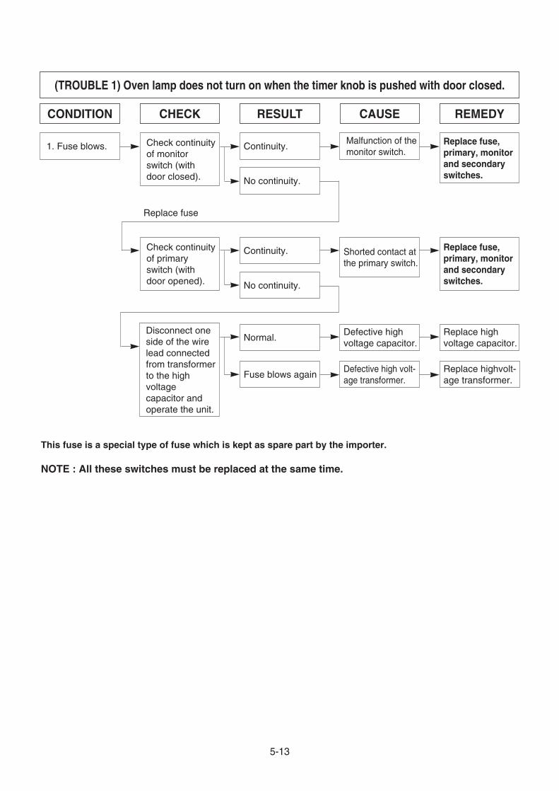
CONDITION CHECK RESULT CAUSE REMEDY
1. Fuse blows. Continuity.
No continuity.
Continuity. Shorted contact atthe primary switch.
Replace fuse,primary, monitorand secondaryswitches.No continuity.
Normal.Defective highvoltage capacitor.
Replace highvoltage capacitor.
Fuse blows againDefective high volt-age transformer.
Replace highvolt-age transformer.
Malfunction of themonitor switch.
Replace fuse,primary, monitorand secondaryswitches.
Check continuityof monitorswitch (withdoor closed).
Check continuityof primaryswitch (withdoor opened).
Disconnect oneside of the wirelead connectedfrom transformerto the highvoltagecapacitor andoperate the unit.
Replace fuse
(TROUBLE 1) Oven lamp does not turn on when the timer knob is pushed with door closed.
This fuse is a special type of fuse which is kept as spare part by the importer.
NOTE : All these switches must be replaced at the same time.

5-14
CONDITION CHECK RESULT CAUSE REMEDY
Output is low Lower than 207V.
Normal
Less than 8.5˚C. Faulty magnetron. Replace.
Decrease in powersource voltagewith load.
Suggest customercontact localelectric powerutility co. orqualifiedelectrician.
Check thepower sourcevoltageoscillating.
Measure themagnetron’soutput(See testprocedure).
(TROUBLE 3) Output power is low.
CONDITION CHECK RESULT CAUSE REMEDY
1.Oven does notoperate. No continuity.
No continuity.
No continuity.
No continuity.
Malfunction of theprimary switch.
Malfunction of thesecondary switch.
Malfunction of thetimer switch.
Faulty thermostat.
Adjust or replace.
Adjust or replace.
replace.
replace.
Check thecontinuity of theprimary switchwith doorclosed.
Check thecontinuity of thesecondaryswitch withsecondaryswitch pushed.
Check thecontinuity of thetimer switchcontacts.
Check thecontinuity of thethermostat.
(TROUBLE 2) Oven does not start even though the timer is set.

5-15
(TROUBLE 4) Oven does not cook at all even though turntable rotates.
No microwaveoscillation.
No continuity.
Continuity.
Malfunction of thepower controlswitch.
Replace the powercontrol switch.Check the
power controlswitch(cookingstate).
Abnormal or burnout.
Abnormal
Abnormal
Defective monitorresistor.
Defective ACrelay.
Open thesecondary windingof the high voltagetransformer offaulty insulation offilament winding.
Replace.
Replace.
Replace.
Check themonitor resistor.
Check the ACrealy.
Check H.V.transformer.
Normal
Abnormal Shorted H.V.diode Replace.Check H.V.diode.
Abnormal Faulty capacitor. Replace.Check H.V.capacitor.
Abnormal Faulty magnetron. Replace.Magnetron
CONDITION CHECK RESULT CAUSE REMEDY

DOOR PARTS
LATCH BOARD PARTS
CONTROL PANEL PARTS
INTERIOR PARTS
BASE PLATE PARTS
OVEN CAVITY PARTS
6-1
EXPLODED VIEW
INTRODUCTION

6-2
DOOR PARTS
13552A
14890A
13213A
13720D
14026A
14970AWTT028
13581A
13536A
13650A

6-3
CONTROLLER PARTS
26549T
24781T
249402
249401
23572A
WTT021

6-4
OVEN CAVITY PARTS
WTT011
35052M
36549S
33390G
34370T
35889A
33112U
WTP013
WTT010

6-5
LATCH BOARD PARTS
466001
466003
WSZ085
466001
43500A

6-6
INTERIOR PARTS
568771
56930G
WSZ062
56411A
50FZZA
56549F56201AWTT028
WSZ002 54974S
WTT03755900A
50CZZH
WSZ002
WTT02854810C
WSZ002
WTT021
30RMZZ
56912B
55262A
948501
56324A
WSZ002
WTP004
969201
56201B
56851C

6-7
BASE PLATE PARTS
56170D
63303A
WSZ002
WTT021
63302A
65006B