![¸ารกำกับดูแล... · 1. 2. 3. 4. 5. 6. 8. IJnn. IJnn. IJmn. l]nn. IJnn. (Conflict of Interest) llnn. nYJå1tuunYJlîl IJnn. nn IJmq. IJnn. IJnn. IJnn. l]nn. Govemance](https://static.fdocuments.us/doc/165x107/5f88be5d657f5364e83927d7/aaaaaaaaaaa-1-2-3-4-5-6-8-ijnn-ijnn-ijmn.jpg)
Microwave Oven NN-ST340W NN-ST340M - Panasonic · 1 FEATURE CHART 4 2 CONTROL PANEL 4 3 SCHEMATIC...
31
© Panasonic Home Appliances Microwave Oven (Shanghai) Co., Ltd. 2011. NN-ST340W NN-ST340M CPH (CANADA) RPH (MEXICO & LATIN AMERICA) Microwave Oven ORDER NO.PHAMOS1101009C1 E1
Transcript of Microwave Oven NN-ST340W NN-ST340M - Panasonic · 1 FEATURE CHART 4 2 CONTROL PANEL 4 3 SCHEMATIC...

© Panasonic Home Appliances Microwave Oven(Shanghai) Co., Ltd. 2011.
NN-ST340WNN-ST340M
CPH (CANADA)RPH (MEXICO & LATIN AMERICA)
Microwave Oven
ORDER NO.PHAMOS1101009C1E1

2
NN-ST340W / NN-ST340M
1 FEATURE CHART 4 2 CONTROL PANEL 4 3 SCHEMATIC DIAGRAM 5
3.1. NN-ST340W CPH 5
3.2. NN-ST340M RPH 6
4 DESCRIPTION OF OPERATING SEQUENCE 7 4.1. Variable power cooking control 7
4.2. Turbo Defrost, Auto Reheat, Auto Cook control 7
5 CAUTIONS TO BE OBSERVED WHEN TROUBLESHOOTING 8 5.1. Check the grounding 8
5.2. Warning about the electric charge in the high voltage
capacitor 8
5.3. Part replacement. 8
5.4. When the 15 Amp fuse is blown due to the malfunction of
the monitor interlock switch: 8
5.5. Avoid inserting nails, wire, etc. through any holes in the
unit during operation. 8
5.6. Verification after repair 8
6 DISASSEMBLY AND PARTS REPLACEMENT PROCEDURE 9 6.1. Magnetron 9
6.2. Digital programmer circuit (D.P.C) & Membrane switch 9
6.3. Low voltage transformer and/or power relays (RY1) 10
6.4. Fan motor 11
6.5. Door assembly 11
6.6. Turntable motor 13
7 COMPONENT TEST PROCEDURE 14 7.1. Primary, Secondary Latch Switch Interlocks 14
7.2. Monitor Interlock Switch 14
7.3. High voltage transformer 14
7.4. High voltage capacitor 14
7.5. Magnetron 14
7.6. Diode 15
7.7. Membrane keyboard (Membrane switch assembly) 15
8 MEASUREMENTS AND ADJUSTMENTS 16 8.1. Adjustment of primary latch switch, secondary latch switch
and monitor interlock switch. 16
8.2. Measurement of microwave output 16
9 PROCEDURE FOR MEASURING MICROWAVE ENERGYLEAKAGE 17 9.1. Equipment 17
9.2. Procedure for measuring radiation leakage 17
9.3. Record keeping and notification after measurement 17
9.4. At least once a year, have the radiation monitor checked
for calibration by its manufacturer. 18
10 TROUBLESHOOTING GUIDE 19 10.1. Trouble related to Digital Programmer Circuit 21
10.2. How to check the semiconductors using an OHM meter 21
11 EXPLODED VIEW AND PARTS LIST 22 11.1. EXPLODED VIEW 22
11.2. PARTS LIST 23
11.3. ESCUTCHEON BASE ASSEMBLY 25
11.4. DOOR ASSEMBLY 26
11.5. WIRING MATERIALS 27
11.6. PACKING AND ACCESSORIES 28
12 DIGITAL PROGRAMMER CIRCUIT 29 12.1. SCHEMATIC DIAGRAM 29
12.2. PARTS LIST 31
CONTENTS Page Page
3
NN-ST340W / NN-ST340M

1 FEATURE CHART
2 CONTROL PANEL
4
NN-ST340W / NN-ST340M

3 SCHEMATIC DIAGRAM3.1. NN-ST340W CPH
5
NN-ST340W / NN-ST340M

3.2. NN-ST340M RPH
6
NN-ST340W / NN-ST340M

4.1. Variable power cookingcontrol
The coil of power relay B (RY1) is energized intermittently bythe digital programmer circuit, when the oven is set at anypower selection except for High power position. The digitalprogrammer circuit controls the ON-OFF time of power relay Bcontacts in order to vary the output power of the microwaveoven from ”Low” to “High” power. One complete ON and OFFcycle of power relay B is 22 seconds. The relation betweenindications on the control panel and the output of themicrowave oven is as shown in table.NOTE:
The ON/OFF time ratio does not correspond with thepercentage of microwave power since approximately 2seconds are required for heating of magnetronfilament.
OUTPUT ON-OFF TIME OFPOWER SETTING POWER(%) POWER RELAY B (RY1)
APPROX. ON(SEC) OFF(SEC)800W 100% 22 0560W 70% 17 5440W 55% 13 9
240W (DEFROST) 30% 9 1380W 10% 5 17
4.2. Turbo Defrost, Auto Reheat,Auto Cook control
When those Auto Control feature is selected and the Start Padis tapped: 1. The digital programmer circuit determines the power level
and cooking time to complete cooking and indicates theoperating state in the display window.Table shows the corresponding cooking times forrespective serving or weight by categories.
2. When cooking time in the display window has elapsed, theoven turns off automatically by a control signal from thedigital programmer circuit.
Turbo DefrostWEIGHT SELECTED COOKING TIME
1.0Kg 15 min.00 sec.
Auto ReheatWEIGHT SELECTED COOKING TIME
1 serving 2 min.00 sec.
Auto CookCATEGORY WEIGHT SELECTED COOKING TIME
Fresh Vegetables 110g 2 min.40 sec.
4 DESCRIPTION OF OPERATING SEQUENCE
7
NN-ST340W / NN-ST340M

Unlike many other appliances, the microwave oven is highvoltage, high current device. Though it is free from danger inordinary use, extreme care should be taken during repair.
CAUTIONServicemen should remove their watches and rings whenever workingclose to or replacing the magnetron.
5.1. Check the groundingDo not operate on a 2-wire extension cord. The microwaveoven is designed to be grounded when used. It is imperative,therefore, to make sure it is grounded properly beforebeginning repair work.
5.2. Warning about the electriccharge in the high voltagecapacitor
For about 30 seconds after the oven is turned off, an electriccharge remains in the high voltage capacitor.When replacing orchecking parts, remove the power plug from the outlet andshort the terminal of the high voltage capacitor (terminal of leadwire from diode) to chassis ground with an insulated handlescrewdriver to discharge. Please be sure to contact the chassisground side first and then short to the output terminal.
WARNINGThere is high voltage present with high current capabilities in thecircuits of the primary and secondary winding and filament winding ofthe high voltage transformer. It is extremely dangerous to work on ornear these circuits with the oven energized.DO NOT measure the voltage in the high voltage circuit includingfilament voltage of the magnetron.
WARNINGNever touch any circuit wiring with your hand nor with an insulatedtool during operation.
5.3. Part replacement.When troubleshooting any part of component is to be replaced,always ensure that the power cord is unplugged from the walloutlet.
5.4. When the 15 Amp fuse isblown due to the malfunctionof the monitor interlockswitch:
WARNINGWhen the 15 Amp fuse is blown due to malfunction of the monitorinterlock switch, replace all of the components (Primary latch switch,Secondary latch switch, Monitor interlock switch).
1. This is mandatory. Refer to “Measurements andAdjustments” for the location of these switches.
2. When replacing the fuse, confirm that it has the appropriaterating for these models.
3. When replacing faulty switches, be sure mounting tabs arenot bent, broken or deficient in their ability to hold theswitches.
5.5. Avoid inserting nails, wire, etc.through any holes in the unitduring operation.
Never insert a wire, nail or any other metal object through thelamp holes on the cavity or any holes or gaps, because suchobjects may work as an antenna and cause microwaveleakage.
5.6. Verification after repair 1. After repair or replacement of parts, make sure that the
screws of the oven, etc. are neither loose nor missing.Microwave energy might leak if screws are not properlytightened.
2. Make sure that all electrical connections are tight beforeinserting the plug into the wall outlet.
3. Check for microwave energy leakage.
CAUTION OFMICROWAVE RADIATION OF LEAKAGE
USE CAUTION NOT TO BECOME EXPOSED TO RADIATIONFROM THE MICROWAVE MAGNETRON OR OTHER PARTSCONDUCTING MICROWAVE ENERGY.
IMPORTANT NOTICE1.The following components have potentials above 2000V while theappliance is operated.* Magnetron* High voltage transformer* High voltage diode* High voltage capacitorPay special attention to these areas.2.When the appliance is operated with the door hinges or magnetroninstalled incorrectly, the microwave leakage can exceed more than5mW/cm2. After repair or exchange, it is very important to check if themagnetron and the door hinges are is correctly installed.
5 CAUTIONS TO BE OBSERVED WHENTROUBLESHOOTING
8
NN-ST340W / NN-ST340M

6.1. Magnetron 1. Discharge the high voltage capacitor. 2. Remove 1 screw holding supporter on the magnetron. 3. Remove 1 screw holding air guide A on cavity top plate.
4. Remove 1 screw holding air guide A on the wave guide,then remove the air guide A.
5. Remove 2 screws holding the magnetron.
NOTE:After replacement of the magnetron,tighten mountingscrews properly, making sure there is no gap betweenthe waveguide and the magnetron to preventmicrowave leakage.
CAUTIONWhen replacing the magnetron, be sure the antenna gasket is inplace.
CAUTIONWhen connecting 2 filament lead wires to the magnetron terminals,be sure to connect the lead wires in the correct position. The lead wireof high volatge transformer should be connected to “FA terminal” andthe lead wire from high voltage capacitor should be connected to “Fterminal”.
6.2. Digital programmer circuit(D.P.C) & Membrane switch
NOTE:Be sure to ground any static electric charge built up onyour body before handling the D.P.C.
1. Remove 1 screw holding escutcheon base on cavity frontplate.
2. Disconnect all connectors from D.P.C. board.
3. Disconnect red case connector from secondary latchswitch.
4. Remove 5 screws holding D.P.C. board on escutcheonbase.
6 DISASSEMBLY AND PARTS REPLACEMENTPROCEDURE
9
NN-ST340W / NN-ST340M
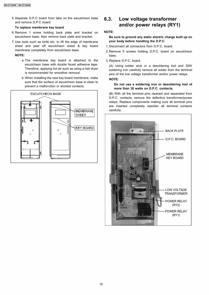
5. Separate D.P.C board from tabs on the escutcheon baseand remove D.P.C board.To replace membrane key board
6. Remove 1 screw holding back plate and bracket onescutcheon base, then remove back plate and bracket.
7. Use tools such as kinfe etc. to lift the edge of membranesheet and peel off escutcheon sheet & key boardmembrane completely from escutcheon base.NOTE:
a. The membrane key board is attached to theescutcheon base with double faced adhesive tape.Therefore, applying hot air such as using a hair dryeris recommended for smoother removal.
b. When installing the new key board membrane, makesure that the surface of escutcheon base is clean toprevent a malfunction or shorted contacts.
6.3. Low voltage transformerand/or power relays (RY1)
NOTE:Be sure to ground any static electric charge built up onyour body before handling the D.P.C.
1. Disconnect all connectors from D.P.C. board. 2. Remove 5 screws holding D.P.C. board on escutcheon
base. 3. Replace D.P.C. board.
(A) Using solder wick or a desoldering tool and 30Wsoldering iron carefully remove all solder from the terminalpins of the low voltage transformer and/or power relays.NOTE:
Do not use a soldering iron or desoldering tool ofmore than 30 watts on D.P.C. contacts.
(B) With all the terminal pins cleaned and separated fromD.P.C. contacts, remove the defective transformer/powerrelays, Replace components making sure all terminal pinsare inserted completely resolder all terminal contactscarefully.
10
NN-ST340W / NN-ST340M

6.4. Fan motor 1. Disconnect 2 lead wires from fan motor terminals. 2. Remove 3 screws holding orifice assy and detach the orifice
assy from oven assy.
3. Remove fan blade from the motor shaft by pulling it straightout.
4. Remove 2 screws holding fan motor on orifice assy anddetach the fan motor from orifice assy.
6.5. Door assembly 1. Support the door, remove 2 screws holding hinge A.
2. Open the door, remove door(U) and hinge A from cavity.NOTE:
Support the door before opening.
3. Remove door C from door A (U) & door E by carefullypulling outward starting from upper right hand corner usinga flat blade screwdriver.
4. Separate door E from tabs on door A (U) and remove doorA (U).
11
NN-ST340W / NN-ST340M

5. Remove door key and door key spring from door E. 6. Replace other components.
To re-install components:NOTE:
After replacement of the defective component partsof the door, reassemble it properly and adjustmentso as to prevent an excessive microwave leakage.Adjustment of the door assembly (Refer page 16).
7. Place the hole of hinge A into the door’s upper hinge pin.
8. Use your left index finger to support the door’s lower hingepin while guiding the door’s hinge A into the cavity slot.Then lower your finger to seat the door onto the hinge.
NOTE:Door alignment is crucial. If door is misaligned,apply pressure until alignment is achieved.
NOTE:Adjust so that the upper portion of the door willtouch firmly to the oven cavity front plate, withoutpushing the door. If the door assembly is notmounted properly, microwave power may leak fromthe clearance between the door and oven.
9. Tighten 2 mounting screws.
Be sure the gap between door E and cavity front plate willbe 0.3~0.7mm.
NOTE:Always perform the microwave leakage measurementtest after installation and adjustment of door assembly.
12
NN-ST340W / NN-ST340M
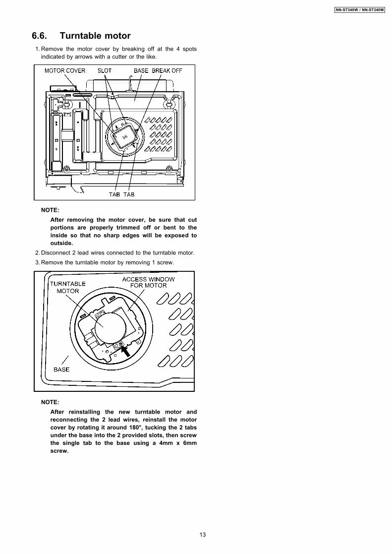
6.6. Turntable motor 1. Remove the motor cover by breaking off at the 4 spots
indicated by arrows with a cutter or the like.
NOTE:After removing the motor cover, be sure that cutportions are properly trimmed off or bent to theinside so that no sharp edges will be exposed tooutside.
2. Disconnect 2 lead wires connected to the turntable motor. 3. Remove the turntable motor by removing 1 screw.
NOTE:After reinstalling the new turntable motor andreconnecting the 2 lead wires, reinstall the motorcover by rotating it around 180°, tucking the 2 tabsunder the base into the 2 provided slots, then screwthe single tab to the base using a 4mm x 6mmscrew.
13
NN-ST340W / NN-ST340M

WARNING1. High voltage is present at the high voltage terminal of the highvoltage transformer during any cook cycle.2. It is neither necessary nor advisable to attempt measurement of thehigh voltage.3. Before touching any oven components, or wiring, always unplugthe power cord and discharge the high voltage capacitor (see page 8).
7.1. Primary, Secondary LatchSwitch Interlocks
1. Unplug lead connectors to Primary Latch Switch andSecondary Latch Switch.
2. Test the continuity of switches at door opened and closedpositions with ohm meter (low scale).Normal continuity readings should be as follows.
7.2. Monitor Interlock Switch 1. Unplug lead wires from H.V.transformer primary terminals. 2. Connect test probes of ohm meter to the disconnected
leads of the H.V. Transformer. 3. Test the continuity of Monitor Interlock Switch with door
opened and closed positions using lowest scale of the ohmmeter.Normal continuity readings should be as follows.
7.3. High voltage transformer 1. Remove connectors from the transformer terminals and
check continuity. 2. Normal (cold) resistance readings should be as follows:
Secondary winding......................... Approx. 195 Ω~240 Ω
Filament winding.............................. Approx. 0 Ω
Primary winding................................. Approx. 0 Ω ~3 Ω
7.4. High voltage capacitor 1. Check continuity of capacitor with meter on highest OHM
scale. 2. A normal capacitor will show continuity for a short time, and
then indicate 9MΩ once the capacitor is charged. 3. A shorted capacitor will show continuous continuity. 4. An open capacitor will show constant 9MΩ. 5. Resistance between each terminal and chassis should be
infinite.
7.5. MagnetronContinuity checks can only indicate an open filament or ashorted magnetron. To diagnose for an open filament orshorted magnetron: 1. Isolate magnetron from the circuit by disconnecting the
leads. 2. A continuity check across magnetron filament terminals
should indicate one ohm or less. 3. A continuity check between each filament terminal and
magnetron case should read open.
7 COMPONENT TEST PROCEDURE
14
NN-ST340W / NN-ST340M

7.6. Diode 1. Isolate the diode from the circuit by disconnecting the leads. 2. With the ohmmeter set on the highest resistance scale,
measure the resistance across the diode terminals.Reversethe meter leads and again observe the resistancereading.Meter with 6V, 9V or higher voltage batteries shouldbe used to check the front-to-back resistance of the diode,otherwise an infinite resistance may be read in bothdirections.A normal diode’s resistance will be infinite in one directionand several hundred KΩ in the other direction.
7.7. Membrane keyboard(Membrane switch assembly)
Check continuity between switch terminals, by tapping anappropriate pad on the key board. The contacts assignment ofthe respective pads on the key board is as shown in digitalprogrammer circuit.
15
NN-ST340W / NN-ST340M

8.1. Adjustment of primary latchswitch, secondary latch switchand monitor interlock switch.
1. Mount the Primary latch switch, the Secondary latch switchand the Monitor interlock switch to the door hook assemblyas shown in illustration.NOTE:
No specific individual adjustments duringinstallation of the Primary latch switch, Secondarylatch switch or Monitor interlock switch to the doorhook are required.
2. When mounting the door hook assembly to the ovenassembly, adjust the door hook assembly by moving it inthe direction of the arrows in the illustration so that the ovendoor will not have any play in it. Check for play in the doorby pulling the door assembly. Make sure that the latch keysmove smoothly after adjustment is completed. Completelytighten the screws holding the door hook assembly to theoven assembly.
3. Reconnect the monitor interlock switch and check thecontinuity of the monitor circuit and all latch switches againby following the component test procedures.
8.2. Measurement of microwaveoutput
The output power of the magnetron can be determined byperforming IEC standard test procedures. However, due to thecomplexity of IEC test procedures, it is recommended to testthe magnetron using the simple method outlined below.Necessary Equipment:*1 liter beaker *Glass thermometer*Wrist watch or stopwatchNOTE:
Check the line voltage under load. Low voltage willlower the magnetron output. Take the temperaturereadings and heating time as accurately as possible.
1. Fill the beaker with exactly one liter of tap water. Stir thewater using the thermometer and record the water’stemperature. (recorded as T1).
2. Place the beaker on the center of glass tray.Set the oven for High power and heat it for exactly oneminute.
3. Stir the water again and read the temperature of the water.(recorded as T2).
4. The normal temperature rise at High power level for eachmodel is as shown in table.
TABLE (1L-1min. test)RATED OUTPUT TEMPERATURE RISE
800W Min. 12.6°F(7.0°C)
8 MEASUREMENTS AND ADJUSTMENTS
16
NN-ST340W / NN-ST340M

NOTE:The U.S. Government standard is 5 mW/cm2 while in thecustomer’s home. 2mW/cm2 stated here is our ownvoluntary standard. (1mW/cm2 for Canada)
9.1. Equipment • Electromagnatic radiation monitor • Glass thermometer 212°F or 100°C • 600cc glass beaker
9.2. Procedure for measuringradiation leakage
Note before measuring: • Do not exceed meter full scale deflection. Leakage monitor
should initially be set to the highest scale. • To prevent false readings, the test probe should be held by
the grip portion of the handle only and moved along theshaded area in Figure no faster than 1 inch/sec(2.5cm/sec).
• Leakage with the outer panel removed: less than 5mW/cm2. • Leakage for a fully assembled oven with door normally
closed: less than 2mW/cm 2 (1mW/cm 2 for Canada). • Leakage for a fully assembled oven [Before the latch switch
(primary) is interrupted] while pulling the door: less than2mW/cm 2.
1. Pour 275 ± 15cc (9ozss± 1/2oz) of 20°C ± 5°C (68° ± 9°F)water in a beaker which is graduated to 600cc, and place inthe center of the oven.
2. Set the radiation monitor to 2450MHz and use it followingthe manufacturer´s recommended test procedure to assurecorrect results.
3. When measuring the leakage, always use the 2 inch (5cm)spacer supplied with the probe.
4. Tap the [Start] button or set the timer and with themagnetron oscillating, measure the leakage by holding theprobe perpendicular to the surface being measured.
9.2.1. Measurement with the outer panelremoved.
Whenever you replace the magnetron, measure for radiationleakage before the outer panel is installed and after allnecessary components are replaced or adjusted. Special careshould be taken in measuring around the magnetron.
9.2.2. Measurements with a fullyassembled oven.
After all components, including outer panel are fully assembled,measure for radiation leakage around the door periphery, thedoor viewing window, the exhaust opening, control panel andair inlet openings.
9.3. Record keeping andnotification after measurement
• After any adjustment or repair to a microwave oven, aleakage reading must be taken. Record this leakagereading on the repair ticket even if it is zero.A copy of this repair ticket and the microwave leakagereading should be kept by repair facility.
• Should the radiation leakage be more than 2 mW/cm2
(1mW/cm2 for Canada) after determining that all parts are ingood condition, functioning properly, and genuinereplacement parts as listed in this manual have been used,immediately notify PSTC, PPR or PCI.
9 PROCEDURE FOR MEASURING MICROWAVE ENERGYLEAKAGE
17
NN-ST340W / NN-ST340M
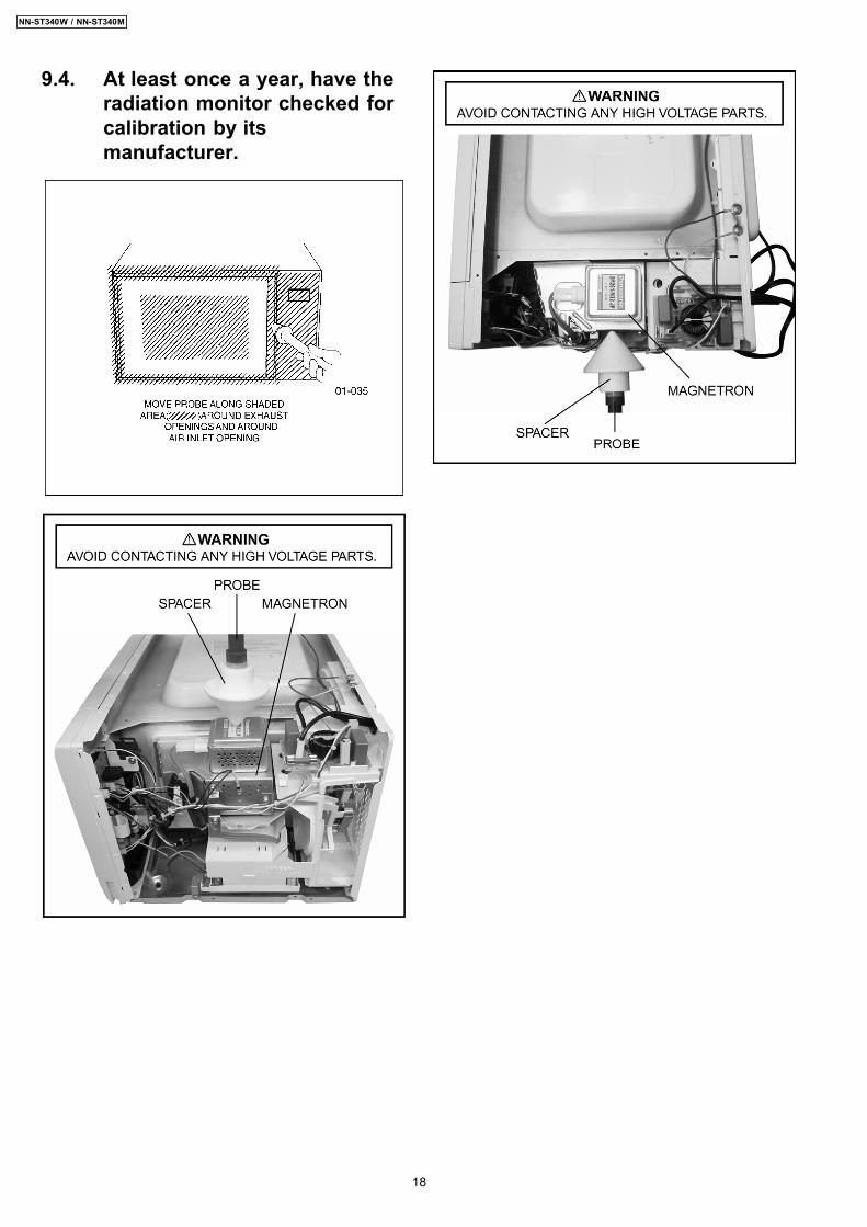
9.4. At least once a year, have theradiation monitor checked forcalibration by itsmanufacturer.
18
NN-ST340W / NN-ST340M

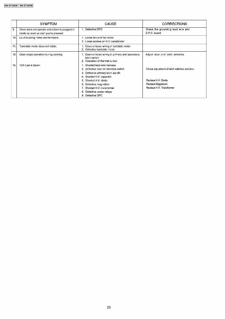
10 TROUBLESHOOTING GUIDEDANGER: HIGH VOLTAGES
1. Ensure proper grounding before troubleshooting.2. Be careful of high voltage circuit.3. Discharge high voltage capacitor.4. When checking the continuity of the switches or the high voltage transformer,disconnect one lead wire from these parts and then checkcontinuity with the AC plug removed. To do otherwise may result in a false reading or damage to your meter.When disconnecting a plastic connector from a terminal, you must hold the plastic connector instead of the lead wire and then disconnect it,otherwise lead wire may be damaged or the connector cannot be removed.5. Do not touch any parts of the circuitry on the digital programmer circuit, since static electric discharge may damage this control panel.Always touch yourself to ground while working on this panel to discharge any static charge in your body.6. 120V AC is present on the digital programmer circuit (Terminals of power relay´s and primary circuit of low voltage transformer). Whentroubleshooting, be cautious of possible electrical shock hazard.
Before troubleshooting, operate the microwave oven following the correct operating procedures in the instruction manual in orderto find the exact cause of any trouble, since operator error may be mistaken for the oven’s malfunction.
19
NN-ST340W / NN-ST340M
20
NN-ST340W / NN-ST340M
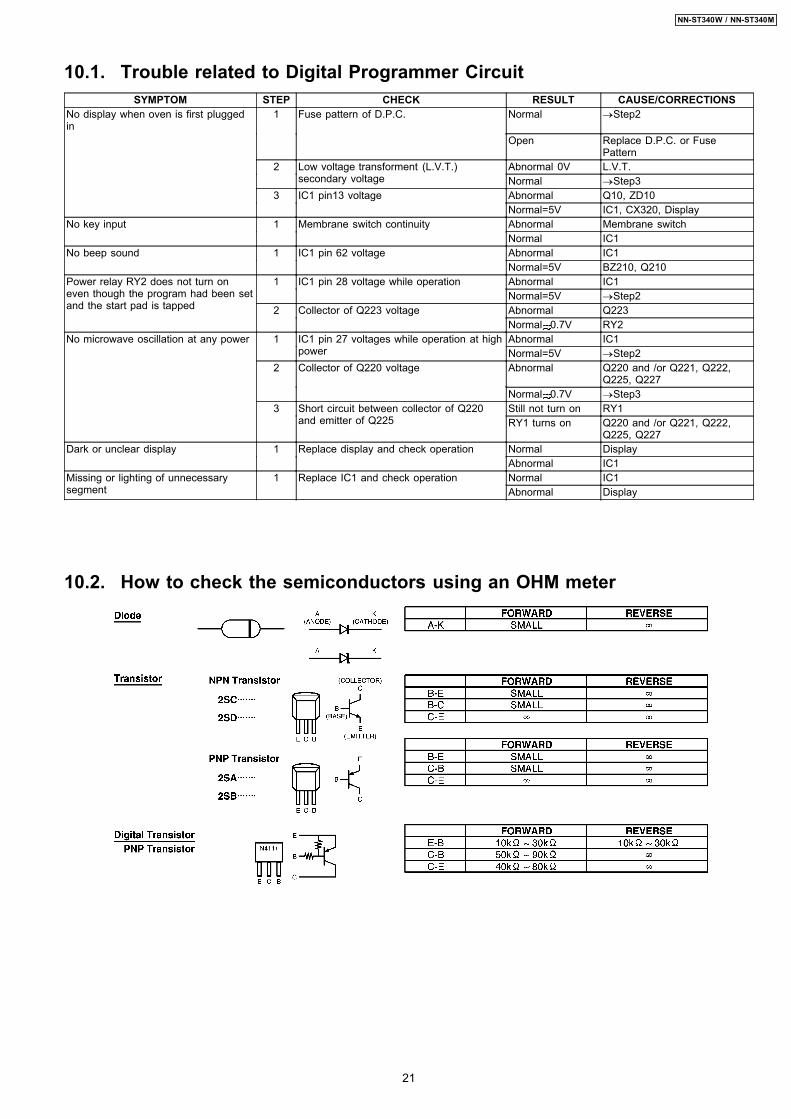
10.1. Trouble related to Digital Programmer CircuitSYMPTOM STEP CHECK RESULT CAUSE/CORRECTIONS
No display when oven is first pluggedin
1 Fuse pattern of D.P.C. Normal →Step2
Open Replace D.P.C. or FusePattern
2 Low voltage transforment (L.V.T.)secondary voltage
Abnormal 0V L.V.T.Normal →Step3
3 IC1 pin13 voltage Abnormal Q10, ZD10Normal=5V IC1, CX320, Display
No key input 1 Membrane switch continuity Abnormal Membrane switchNormal IC1
No beep sound 1 IC1 pin 62 voltage Abnormal IC1Normal=5V BZ210, Q210
Power relay RY2 does not turn oneven though the program had been setand the start pad is tapped
1 IC1 pin 28 voltage while operation Abnormal IC1Normal=5V →Step2
2 Collector of Q223 voltage Abnormal Q223Normal 0.7V RY2
No microwave oscillation at any power 1 IC1 pin 27 voltages while operation at highpower
Abnormal IC1Normal=5V →Step2
2 Collector of Q220 voltage Abnormal Q220 and /or Q221, Q222,Q225, Q227
Normal 0.7V →Step33 Short circuit between collector of Q220
and emitter of Q225Still not turn on RY1RY1 turns on Q220 and /or Q221, Q222,
Q225, Q227Dark or unclear display 1 Replace display and check operation Normal Display
Abnormal IC1Missing or lighting of unnecessarysegment
1 Replace IC1 and check operation Normal IC1Abnormal Display
10.2. How to check the semiconductors using an OHM meter
21
NN-ST340W / NN-ST340M
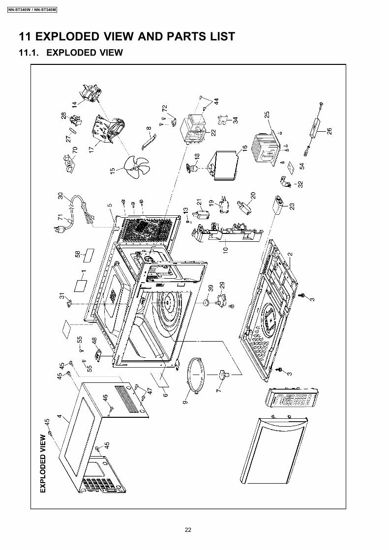
11 EXPLODED VIEW AND PARTS LIST11.1. EXPLODED VIEW
22
NN-ST340W / NN-ST340M

11.2. PARTS LISTNOTE:
1. When ordering replacement part(s), please use part number(s) shown in this part list.Do not use description of the part.
2. Important safety notice:Components identified by mark have special characteristics important for safety.When replacing any of these components, use only manufacture’s specified parts.
NOTE:“A” parts are supplied by MOBU (Japan)“F” parts are supplied by PHAMOS (China)
Ref. No. Part No. Part Name & Description Pcs/Set Remarks1 F00079V30HCP NAME PLATE 1 ST340W CPH1 F00079V30SRP NAME PLATE 1 ST340M RPH2 F10019V00XP BASE 13 F10084T00APS RUBBER FOOT 24 F10099V00HXP CABINET BODY 1 ST340W CPH4 F10099V00SXP CABINET BODY 1 ST340M RPH5 F200A9V60AP OVEN 1
6 F20559V00XP COVER 17 F21319W00XP PULLY SHAFT 18 F20349V00XP SUPPORTER 19 F290D9W00XP ROLLER RING (U) 110 F30209V00XP DOOR HOOK 1
13 F30799V00XP SPRING 114 F400A9V60AP FAN MOTOR 115 F4008-1N00 FAN BLADE 1
16 F40259V00XP AIR GUIDE A 117 F41449V00XP ORIFICE 118 F612E9V30AP INCANDESCENT LAMP (U) 119 F61425U30XN MICRO SWITCH B 1 (PRIMARY LATCH SWITCH)20 F61415U30XN MICRO SWITCH A 1 (SECONDARY LATCH SWITCH)
21 F61789V00XP MICRO SWITCH 1 (MONITOR INTERLOCK SWITCH)22 2M210-M36R MAGNETRON 123 F60909V30HP H.V. CAPACITOR 1 (0.94µF/2100V)25 F621B9V30HP H.V.TRANSFORMER 1
26 F62025G10XN DIODE 127 F62306V60AP FUSE 1 15A28 F62319V00XP FUSE HOLDER 1 RPH29 F63266S30AP TURNTABLE MOTOR 130 F900C9V30AP AC CORD W/PLUG 1
31 F61459V00XP THERMAL CUTOUT 1 130°C OPEN, -20°C CLOSE32 F60379V00XP CAPACITOR BRACKET 134 F60706S10XP INSULATE BRACKET 1
39 F21766S10XP SEAL 1
44 XTWFL4+12T SCREW 2 FOR MAGNETRON45 XTWBFE4+8D SCREW 4 FOR CABINET BODY
46 XTC4+10BFN SCREW 1 FOR CABINET BODY SIDE (UPPER SIDE)47 XTTFL4+6BN SCREW 2 FOR CABINET BODY SIDE (LOWER SIDE)48 F30069V00XP HINGE A 1
54 F60709V00XP INSULATION SHEET 155 XTWFA4+12LR SCREW 2 FOR HINGE A
58 F00067600CP CAUTION LABEL 1 CPH58 F00069660AP CAUTION LABEL 1 RPH
70 F692Y9V60AP NOISE FILTER (U) 1 CPH72 F61456S10XP THERMAL CUTOUT 1 180°C OPEN,60°C CLOSE (ST340W CPH)
76 F00339V30AP FUSE LABEL 1
23
NN-ST340W / NN-ST340M

Ref. No. Part No. Part Name & Description Pcs/Set Remarks77 F00067C50CP CAUTION LABEL 1 CPH78 F03349V30CP MENU LABEL 1 ST340W CPH78 F03349V30RP MENU LABEL 1 ST340M RPH
24
NN-ST340W / NN-ST340M
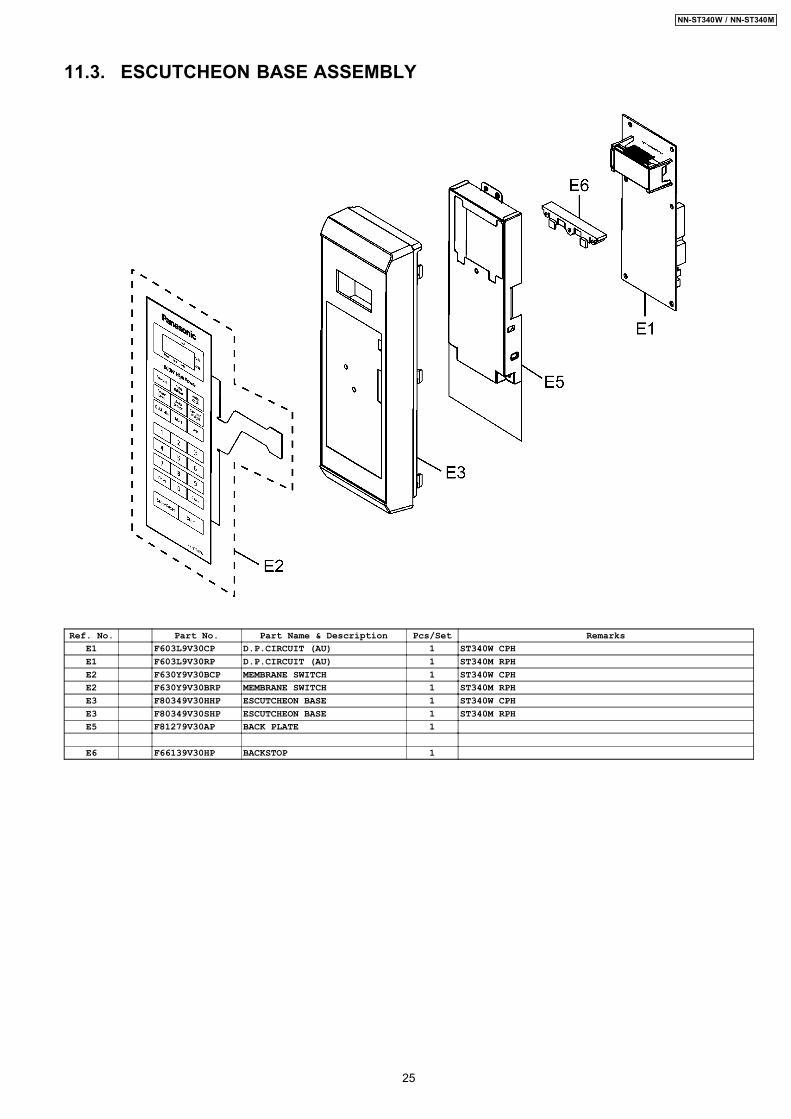
11.3. ESCUTCHEON BASE ASSEMBLY
Ref. No. Part No. Part Name & Description Pcs/Set RemarksE1 F603L9V30CP D.P.CIRCUIT (AU) 1 ST340W CPHE1 F603L9V30RP D.P.CIRCUIT (AU) 1 ST340M RPHE2 F630Y9V30BCP MEMBRANE SWITCH 1 ST340W CPHE2 F630Y9V30BRP MEMBRANE SWITCH 1 ST340M RPHE3 F80349V30HHP ESCUTCHEON BASE 1 ST340W CPHE3 F80349V30SHP ESCUTCHEON BASE 1 ST340M RPHE5 F81279V30AP BACK PLATE 1
E6 F66139V30HP BACKSTOP 1
25
NN-ST340W / NN-ST340M

11.4. DOOR ASSEMBLY
Ref. No. Part No. Part Name & Description Pcs/Set RemarksD1 F30189V00XP DOOR KEY A 1D2 F302A9V00HXP DOOR A (U) 1 ST340W CPHD2 F302A9V00SXP DOOR A (U) 1 ST340M RPHD3 F302K9V00XP DOOR E (U) 1D4 F30215G10XN DOOR KEY SPRING 1D5 F30859V00XP DOOR C 1
D6 F31455G10AP DOOR SCREEN A 1 ST340W CPHD6 F31455G10XN DOOR SCREEN A 1 ST340M RPHD9 F04114180CP HC LABEL 1 CPHD9 F02459660AP DHHS LABEL 1 RPH
26
NN-ST340W / NN-ST340M

11.5. WIRING MATERIALS
Ref. No. Part No. Part Name & Description Pcs/Set RemarksW1 F030A9V30CP LEAD WIRE HARNESS 1 ST340W CPHW1 F030A9V30RP LEAD WIRE HARNESS 1 ST340M RPH
27
NN-ST340W / NN-ST340M

11.6. PACKING AND ACCESSORIES
Ref. No. Part No. Part Name & Description Pcs/Set RemarksP1 F00039V30CP INSTRUCTION MANUAL 1 ST340W CPHP1 F00039V30RP INSTRUCTION MANUAL 1 ST340M RPHP2 F01029V30HCP PACKING CASE,PAPER 1 ST340W CPHP2 F01029V30SRP PACKING CASE,PAPER 1 ST340M RPHP3 F01049V00XP UPPER FILLER 1P4 F01059V00XP LOWER FILLER 1P5 F01068100XN P.E.BAG 1
P6 F01075G10XN DOOR SHEET 1P7 F06019W00XP COOKING TRAY 1P8 F01924T00AP SHEET 1
P10 F00065G40AP CAUTION LABEL 1 RPHP12 F04459V30HCP OVERLAY 1 ST340W CPH
P17 F01569M50MP OPERATION PRECAUTION 1 RPH
28
NN-ST340W / NN-ST340M

12 DIGITAL PROGRAMMER CIRCUIT12.1. SCHEMATIC DIAGRAM
29
NN-ST340W / NN-ST340M

30
NN-ST340W / NN-ST340M

12.2. PARTS LISTRef. No. Part No. Part Name & Description Pcs/Set Remarks
BZ210 L0DDEA000014 BUZZER 1 2.0KHzC10 F2A1V221B280 AL CHEM CAPACITOR 1 220µF/35VC11 F2A1C220B624 AL CHEM CAPACITOR 1 22µF/16VDISP110 AEDDHL9V30QP LCD 1
F66179V30HP LCD HOLDER 1D40,D41,D220,D221,D223,D227,D228
B0AACK000004 DIODE 7
D10-D13 B0EAKT000025 DIODE 4D25 D4EAY271A036 ZENER RESISTOR 1 270VD26,D27 D4EAY112A036 ZENER RESISTOR 2 1100VIC1 MN69F009AAB L.S.I. 1Q10,Q180 B1BAAJ000003 TRANSISTOR 2RY1 K6B1AZA00016 POWER RELAY 1RY2 K6B1AZA00010 POWER RELAY 1ZD10 B0BA5R600016 ZENER DIODE 1T10 G4C2AAD00006 LOW VOLTAGE TRANSFORMER 1
31
NN-ST340W / NN-ST340M
01/11S-9V3Printed in China