Microwave Oven NN-SE992S NN-SD982S NN-ST962S · Unlike many other appliances, the microwave oven is...
38
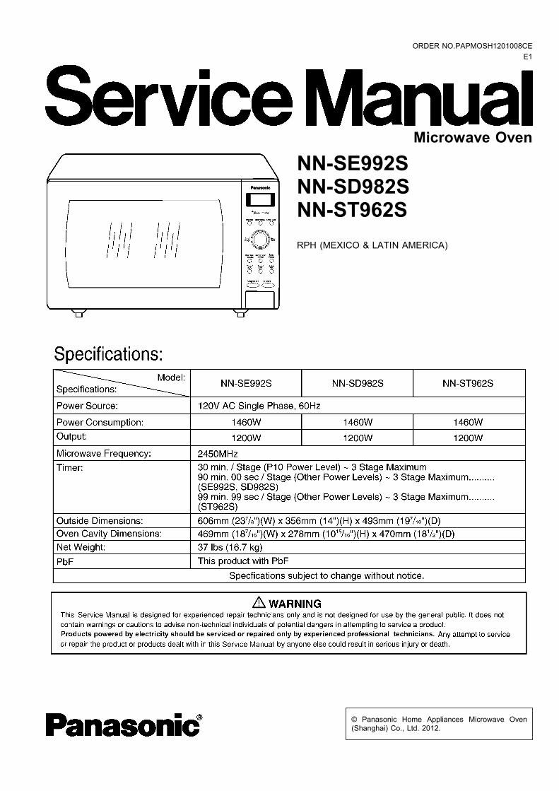
© Panasonic Home Appliances Microwave Oven (Shanghai) Co., Ltd. 2012. NN-SE992S NN-SD982S NN-ST962S RPH (MEXICO & LATIN AMERICA) Microwave Oven ORDER NO.PAPMOSH1201008CE E1
Transcript of Microwave Oven NN-SE992S NN-SD982S NN-ST962S · Unlike many other appliances, the microwave oven is...
© Panasonic Home Appliances Microwave Oven(Shanghai) Co., Ltd. 2012.
NN-SE992SNN-SD982SNN-ST962SRPH (MEXICO & LATIN AMERICA)
Microwave Oven
ORDER NO.PAPMOSH1201008CEE1
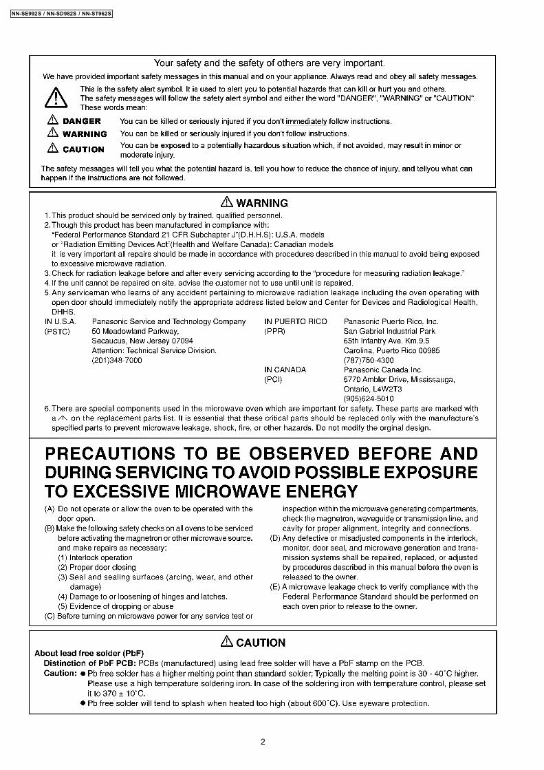
2
NN-SE992S / NN-SD982S / NN-ST962S
3
NN-SE992S / NN-SD982S / NN-ST962S

1 SCHEMATIC DIAGRAM 5 2 DESCRIPTION OF OPERATING SEQUENCE 6
2.1. Variable power cooking control 6
2.2. Inverter power supply circuit 6
2.3. Inverter defrost 6
2.4. Sensor cooking 6
2.5. Sensor reheat 7
2.6. Steam sensor and digital programmer circuit 7
3 CAUTIONS TO BE OBSERVED WHEN TROUBLESHOOTING 8 3.1. Check the grounding 8
3.2. Inverter warnings 8
3.3. Part replacement. 9
3.4. When the 20A fuse is blown due to the malfunction of the
monitor switch: 9
3.5. Avoid inserting nails, wire etc. through any holes in the
unit during operation. 9
3.6. Verification after repair 9
3.7. Sharp edges 9
4 DISASSEMBLY AND PARTS REPLACEMENT PROCEDURE 10 4.1. Magnetron 10
4.2. Digital programmer circuit (D.P.C) 10
4.3. Low voltage transformer and/or power relays (RY1, RY2)
11
4.4. Fan motor 11
4.5. Door assembly 11
4.6. Turntable motor 12
4.7. Steam sensor 12
4.8. Inverter power supply 13
5 COMPONENT TEST PROCEDURE 14 5.1. Primary, Secondary Interlock Switch & Power Relay RY1
14
5.2. Monitor Switch 14
5.3. Magnetron 14
5.4. key board membrane (Membrane switch assembly) 14
5.5. Inverter power supply (U) 15
5.6. Temperature thermistor 15
6 MEASUREMENTS AND ADJUSTMENTS 16 6.1. Adjustment of primary interlock switch, secondary interlock
switch and monitor switch. 16
6.2. Measurement of microwave output 16
7 PROCEDURE FOR MEASURING MICROWAVE ENERGYLEAKAGE 17 7.1. Equipment 17
7.2. Procedure for measuring radiation leakage 17
7.3. Record keeping and notification after measurement 17
8 TROUBLESHOOTING GUIDE 18 8.1. (Troubleshooting) Oven stops operation during cooking 19
8.2. (Troubleshooting) Other problems 20
8.3. Troubleshooting of inverter circuit (U) and magnetron 21
8.4. Trouble related to Digital Programmer Circuit 22
8.5. SIMPLE WAY OF H.V. INVERTER/MAGNETRON
TROUBLESHOOTING 25
8.6. H.V.INVERTER BOARD MAIN PARTS LIST
(F606Y8X00AP) 25
8.7. How to check the semiconductors using an OHM meter 26
9 EXPLODED VIEW AND PARTS LIST 27 9.1. EXPLODED VIEW 27
9.2. PARTS LIST 28
9.3. ESCUTCHEON BASE ASSEMBLY 29
9.4. DOOR ASSEMBLY 32
9.5. WIRING MATERIALS 33
9.6. PACKING AND ACCESSORIES 34
10 DIGITAL PROGRAMMER CIRCUIT 35 10.1. SCHEMATIC DIAGRAM (NN-SE992S) 35
10.2. SCHEMATIC DIAGRAM (NN-SD982S) 37
10.3. SCHEMATIC DIAGRAM (NN-ST962S) 39
10.4. PARTS LIST 41
CONTENTS Page Page
4
NN-SE992S / NN-SD982S / NN-ST962S
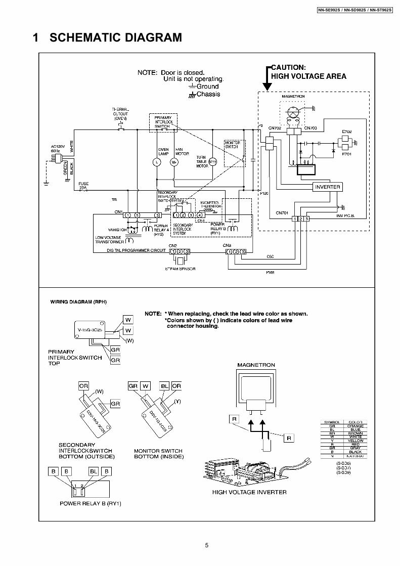
1 SCHEMATIC DIAGRAM
5
NN-SE992S / NN-SD982S / NN-ST962S
2.1. Variable power cookingcontrol
High Voltage Inverter Power Supply (U) controls output powerby the signal from Digital Programmer Circuit (DPC). Powerrelay always stay on, but PWM (Pulse Width Modulation) signalcontrols microwave output power.NOTE:
The ON/OFF time ratio does not correspond with thepercentage of microwave power since approximately 2seconds are required for heating of magnetronfilament.
Variable Power CookingPOWER SETTING OUTPUT
POWER(%)APPROX.
MANUAL MICROWAVEDUTY
ON(SEC) OFF(SEC)HIGH P10 100% 22 0
P9 90% 22 0P8 80% 22 0
MEDIUM-HIGH P7 70% 22 0MEDIUM P6 60% 22 0
P5 50% 22 0P4 40% 22 0
MEDIUM-LOW P3 30% 22 0P2 20% 15 7P1 10% 8 14
2.2. Inverter power supply circuitThe Inverter Power Supply circuit powered from the linevoltage, 120V 60Hz AC input supplies 4,000V DC to themagnetron tube, and functions in place of the H.V. transformer,the H.V. capacitor and H.V. diode. 1. The AC input voltage 120V 60Hz is rectified to DC voltage
immediately. 2. DC voltage will be supplied to the switching devices called
IGBT. These devices are switched ON-OFF by the 20 to 40kHz PWM (pulse width modulation) signal from themicrocomputer in the DPC.
3. This drives the High voltage transformer to increase voltageup to 2,000V AC.
4. Then the half-wave doubler voltage rectifier circuit,consisting of the H.V. diodes and capacitors, generates thenecessary 4,000V DC needed for the magnetron.
5. Output power of the magnetron tube is always monitored bythe signal output from the current transformer built into theinverter circuit.
6. This signal is fed back to the microcomputer in the DPC todetermine operating conditions and output necessary tocontrol PWM signal to the Inverter Power Supply for controlof the output power.
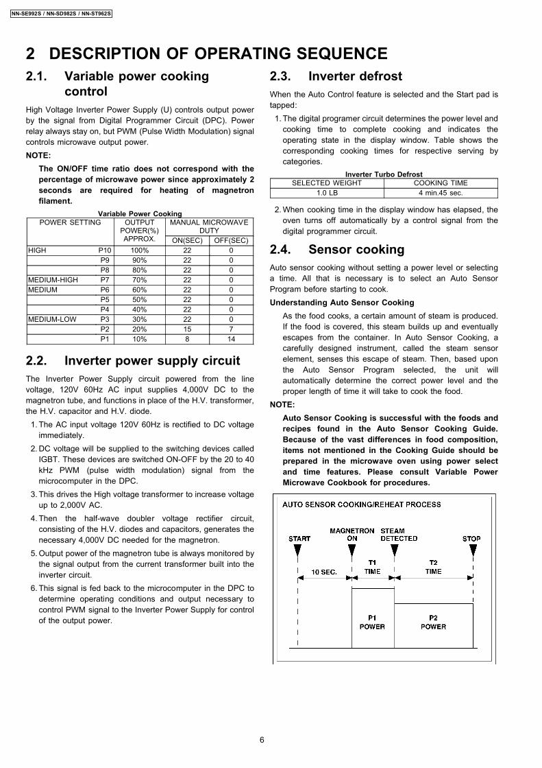
2.3. Inverter defrostWhen the Auto Control feature is selected and the Start pad istapped: 1. The digital programer circuit determines the power level and
cooking time to complete cooking and indicates theoperating state in the display window. Table shows thecorresponding cooking times for respective serving bycategories.
Inverter Turbo DefrostSELECTED WEIGHT COOKING TIME
1.0 LB 4 min.45 sec.
2. When cooking time in the display window has elapsed, theoven turns off automatically by a control signal from thedigital programmer circuit.
2.4. Sensor cookingAuto sensor cooking without setting a power level or selectinga time. All that is necessary is to select an Auto SensorProgram before starting to cook.Understanding Auto Sensor Cooking
As the food cooks, a certain amount of steam is produced.If the food is covered, this steam builds up and eventuallyescapes from the container. In Auto Sensor Cooking, acarefully designed instrument, called the steam sensorelement, senses this escape of steam. Then, based uponthe Auto Sensor Program selected, the unit willautomatically determine the correct power level and theproper length of time it will take to cook the food.
NOTE:Auto Sensor Cooking is successful with the foods andrecipes found in the Auto Sensor Cooking Guide.Because of the vast differences in food composition,items not mentioned in the Cooking Guide should beprepared in the microwave oven using power selectand time features. Please consult Variable PowerMicrowave Cookbook for procedures.
2 DESCRIPTION OF OPERATING SEQUENCE
6
NN-SE992S / NN-SD982S / NN-ST962S

Explanation of the Auto Sensor Cooking process 1. During the first 10 second period there is no microwave
activity. When calculating the T2 time by using theformula below make sure this 10 seconds is subtractedfrom the T1 time. In other words, T1 time starts at theend of the 10 second period.
2. T1 time The total amount of time it takes the microwaveoven to switch to T2 time after the 10second period.
3. T2 time When the steam escapes from the cookingcontainer placed in the oven, the steam sensor detectsit and the microprocessor calculates the balance ofcooking time. This T2 time is then shown in the displayand begins counting down.Balance of cooking time (T2 time)The balance of cooking time which is called T2 time,can be calculated by the following formula.T2 time (in sec.) = T1 time X K factor - 150
NOTE:Remember, the T1 time starts after the 10 secondperiod. The coefficient K is programmed into themicroprocessor memory and they are listed in thefollowing tables along with the P1 and P2 powers.
NOTE:When "More" or "Less" pad is selected, the K factorvaries resulting in T2 time to be increased or decreased.
Example of calculating the T2 timeExample 1: If the T1 time is measured to be 2 minutes and40 seconds after the 10 second period.T2 = T1 × K - 150 sec.= 2 min. and 40 sec. × 1.1 - 150 sec.= 160sec. × 1.1 - 150 sec.= 26 sec.
Category P1Power
P2Power
K FactorStandard
Omelet MEDIUM MEDIUM 0.6
2.5. Sensor reheatAuto Sensor Reheat is a quick and easy way to reheatrefrigerated and room temperature foods.Simply press the reheat pad. There is no need to select powerlevel and cooking time.NOTE:
The Auto Sensor Reheat process is similar as Auto SensorCooking process.
Balance of cooking time (T2 time)The balance of cooking time which is called T2 time, can becalculated by the following formula.T2 time (in sec.) = T1 time X K factor - 150NOTE:
Remember, the T1 time starts after the 10 second period.The coefficient K is programmed into the microprocessormemory and they are listed in the following tables alongwith the P1 and P2 powers.
NOTE:When "More" or "Less" pad is selected, the K factor variesresulting in T2 time to be increased or decreased.
Example of calculating the T2 timeExample 1: If the T1 time is measured to be 2 minutes and40 seconds after the 10 second period.T2 = T1 × K - 150 sec.= 2 min. and 40 sec. × 1.1 - 150 sec.= 160sec. × 1.1 - 150 sec.= 26 sec.
Category P1Power
P2Power
K FactorStandard
Sensor Reheat HIGH MEDIUM 0.2
2.6. Steam sensor and digitalprogrammer circuit
In order to determine if the steam sensor function of the digitalprogrammer circuit is working, do the following test. 1. Place a water load (100 cc) in the oven. 2. Tap Sensor Reheat pad. 3. Tap Start pad. 4. Steam Sensor detects steam about 1.5 to 2 minutes after
the Start pad is tapped. 5. T1 time cooking automatically switches to remaining time
for cooking (T2). 6. The remaining cooking time (T2) appears in display
window. If the following cooking time appears, SteamSensor function is normal.
T1 TIME T2 TIME (Remaining cookingtime)
50 Sec. ~ 2 Min. 0 Sec. ~ 24 Sec.
7
NN-SE992S / NN-SD982S / NN-ST962S
Unlike many other appliances, the microwave oven is a highvoltage, high current device. It is free from danger in ordinaryuse, though extreme care should be taken during repair.
CAUTIONServicemen should remove their watches and ringswhenever working close to or replacing the magnetron.
3.1. Check the groundingDo not operate on a two wire extension cord. The microwaveoven is designed to be grounded when used. It is imperative,therefore, to ensure the appliance is properly grounded beforebeginning repair work.
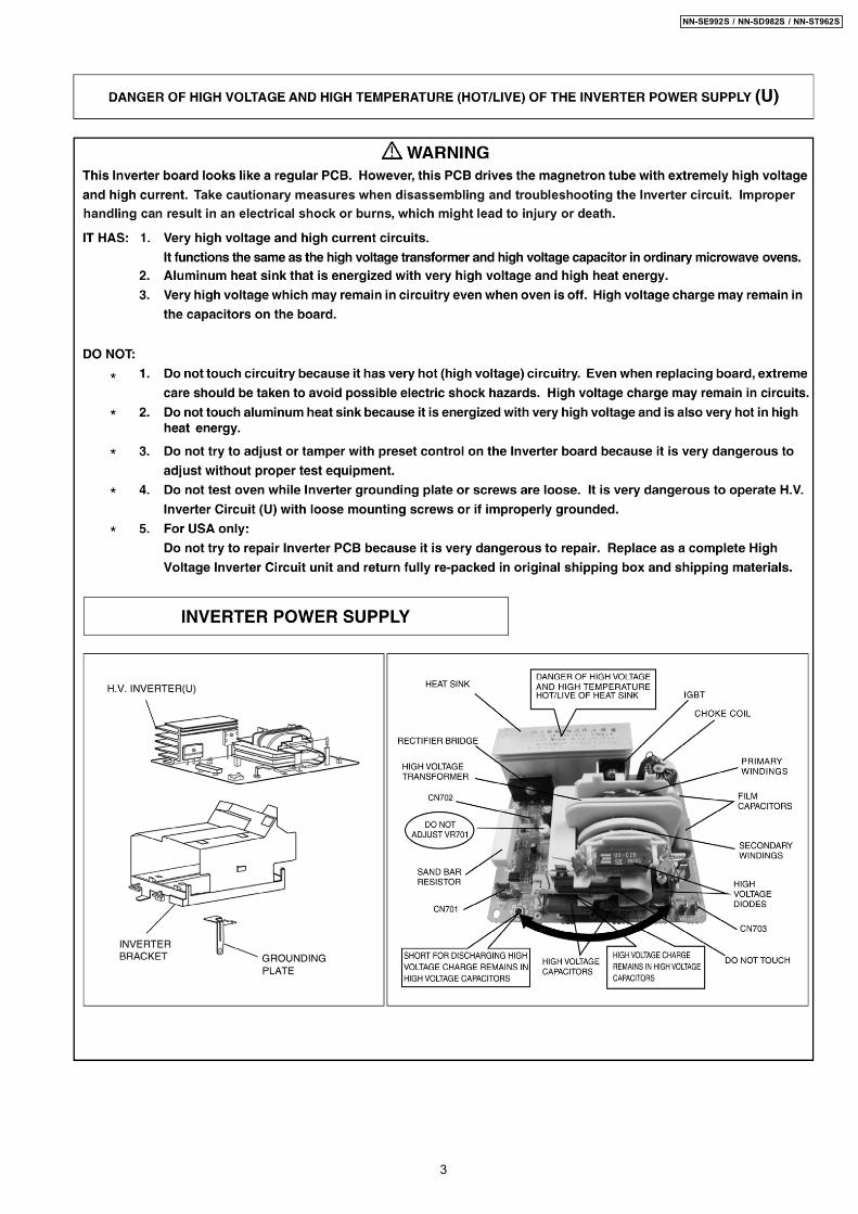
3.2. Inverter warningsWARNING HIGH VOLTAGE AND HIGHTEMPERATURE
(HOT/LIVE) OF THE INVERTERPOWER SUPPLY (U)The High Voltage Inverter Power Supply generates veryhigh voltage and current for the magnetron tube. Though itis free from danger in ordinary use, extreme care should betaken during repair.The aluminum heat sink is also energized with high voltage(HOT), do not touch when the AC input terminals areenergized. The power device Collector is directly connectedto the aluminum heat sink.The aluminum heat sink may be HOT due to heat energy,therefore, extreme care should be taken during servicing.
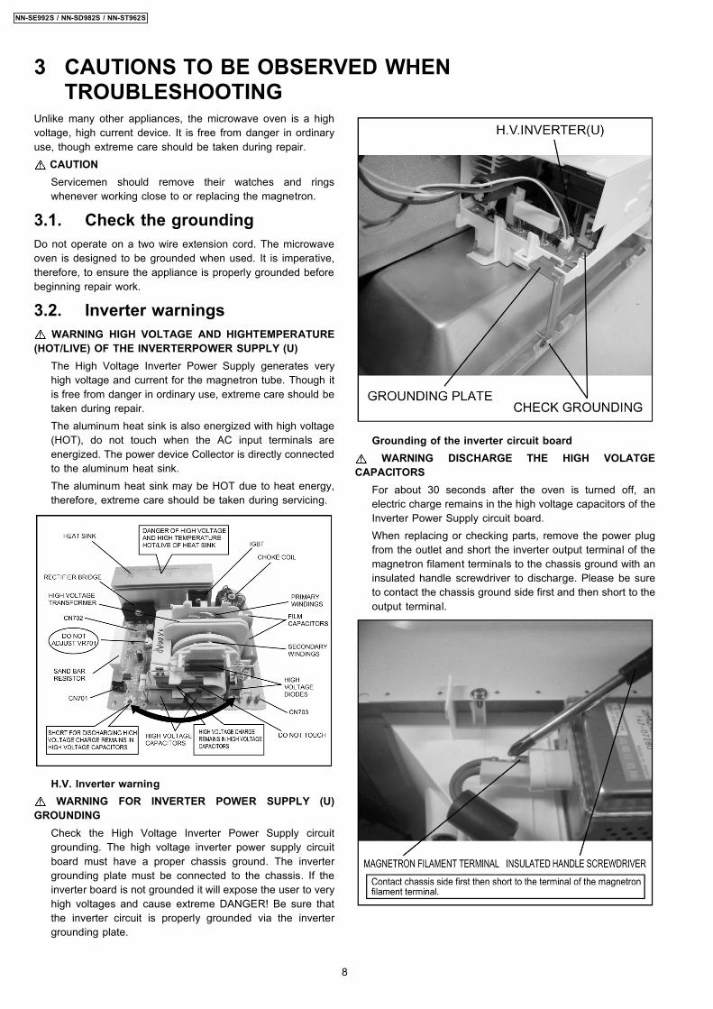
H.V. Inverter warningWARNING FOR INVERTER POWER SUPPLY (U)
GROUNDINGCheck the High Voltage Inverter Power Supply circuitgrounding. The high voltage inverter power supply circuitboard must have a proper chassis ground. The invertergrounding plate must be connected to the chassis. If theinverter board is not grounded it will expose the user to veryhigh voltages and cause extreme DANGER! Be sure thatthe inverter circuit is properly grounded via the invertergrounding plate.
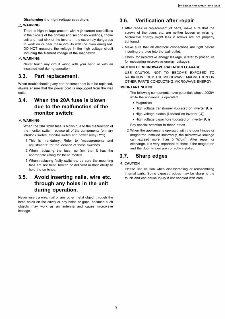
Grounding of the inverter circuit boardWARNING DISCHARGE THE HIGH VOLATGE
CAPACITORSFor about 30 seconds after the oven is turned off, anelectric charge remains in the high voltage capacitors of theInverter Power Supply circuit board.When replacing or checking parts, remove the power plugfrom the outlet and short the inverter output terminal of themagnetron filament terminals to the chassis ground with aninsulated handle screwdriver to discharge. Please be sureto contact the chassis ground side first and then short to theoutput terminal.
3 CAUTIONS TO BE OBSERVED WHENTROUBLESHOOTING
8
NN-SE992S / NN-SD982S / NN-ST962S
Discharging the high voltage capacitorsWARNINGThere is high voltage present with high current capabilitiesin the circuits of the primary and secondary windings, chokecoil and heat sink of the inverter. It is extremely dangerousto work on or near these circuits with the oven energized.DO NOT measure the voltage in the high voltage circuitincluding the filament voltage of the magnetron.WARNINGNever touch any circuit wiring with your hand or with aninsulated tool during operation.
3.3. Part replacement.When troubleshooting any part or component is to be replaced,always ensure that the power cord is unplugged from the walloutlet.
3.4. When the 20A fuse is blowndue to the malfunction of themonitor switch:
WARNINGWhen the 20A 120V fuse is blown due to the malfunction ofthe monitor switch, replace all of the components (primaryinterlock switch, monitor switch and power relay RY1). 1. This is mandatory. Refer to “measurements and
adjustments” for the location of these switches. 2. When replacing the fuse, confirm that it has the
appropriate rating for these models. 3. When replacing faulty switches, be sure the mounting
tabs are not bent, broken or deficient in their ability tohold the switches.
3.5. Avoid inserting nails, wire etc.through any holes in the unitduring operation.
Never insert a wire, nail or any other metal object through thelamp holes on the cavity or any holes or gaps, because suchobjects may work as an antenna and cause microwaveleakage.
3.6. Verification after repair 1. After repair or replacement of parts, make sure that the
screws of the oven, etc. are neither loosen or missing.Microwave energy might leak if screws are not properlytightened.
2. Make sure that all electrical connections are tight beforeinserting the plug into the wall outlet.
3. Check for microwave energy leakage. (Refer to procedurefor measuring microwave energy leakage).
CAUTION OF MICROWAVE RADIATION LEAKAGEUSE CAUTION NOT TO BECOME EXPOSED TORADIATION FROM THE MICROWAVE MAGNETRON OROTHER PARTS CONDUCTING MICROWAVE ENERGY.
IMPORTANT NOTICE 1. The following components have potentials above 2000V
while the appliance is operated. • Magnetron • High voltage transformer (Located on inverter (U)) • High voltage diodes (Located on inverter (U)) • High voltage capacitors (Located on inverter (U))Pay special attention to these areas.
2. When the appliance is operated with the door hinges ormagnetron installed incorrectly, the microwave leakagecan exceed more than 5mW/cm2. After repair orexchange, it is very important to check if the magnetronand the door hinges are correctly installed.
3.7. Sharp edgesCAUTIONPlease use caution when disassembling or reassemblinginternal parts. Some exposed edges may be sharp to thetouch and can cause injury if not handled with care.
9
NN-SE992S / NN-SD982S / NN-ST962S

WARNING1. High voltage is present at the output terminals of the High VoltageInverter (U) including aluminum heat sink during any cook cycle.2. It is neither necessary nor advisable to attempt measurement of thehigh voltage.3. Before touching any oven components, or wiring, always unplugthe power cord and discharge the high voltage capacitors (see page8 ).
5.1. Primary, Secondary InterlockSwitch & Power Relay RY1
1. Unplug lead connectors to Power Relay RY1 and verifyopen circuit of the Power Relay RY1 1-2 terminals.
2. Unplug lead connectors to Primary Interlock Switch andSecondary Interlock Switch.
3. Test the continuity of switches at door opened and closedpositions with ohm meter (low scale).Normal continuity readings should be as follows.
Door Closed Door OpenedPrimary Interlock Switch 0Ω (Close) Ω(Open)Secondary Interlock Switch 0Ω (Close) Ω(Open)Power Relay RY1 Ω (Open) Ω(Open)
5.2. Monitor Switch 1. Unplug lead wires from Inverter Power Supply (U) primary
terminals. 2. Connect test probes of ohm meter to the disconnected
leads that were connected to Inverter Power Supply (U). 3. Test the continuity of Monitor Switch with door opened and
closed positions using lowest scale of the ohm meter.Normal continuity readings should be as follows.
Door Opened Door Closed0Ω (Close) Ω (Open)
5.3. MagnetronContinuity checks can only indicate an open filament or ashorted magnetron. To diagnose for an open filament orshorted magnetron. 1. Isolate magnetron from the circuit by disconnecting the
leads. 2. A continuity check across magnetron filament terminals
should indicate one ohm or less. 3. A continuity check between each filament terminal and
magnetron case should read open.
5.4. key board membrane(Membrane switch assembly)
Check continuity between switch terminals, by tapping anappropriate pad on the key board. The contacts assignment ofthe respective pads on the key board is as shown in digitalprogrammer circuit.
5 COMPONENT TEST PROCEDURE
14
NN-SE992S / NN-SD982S / NN-ST962S
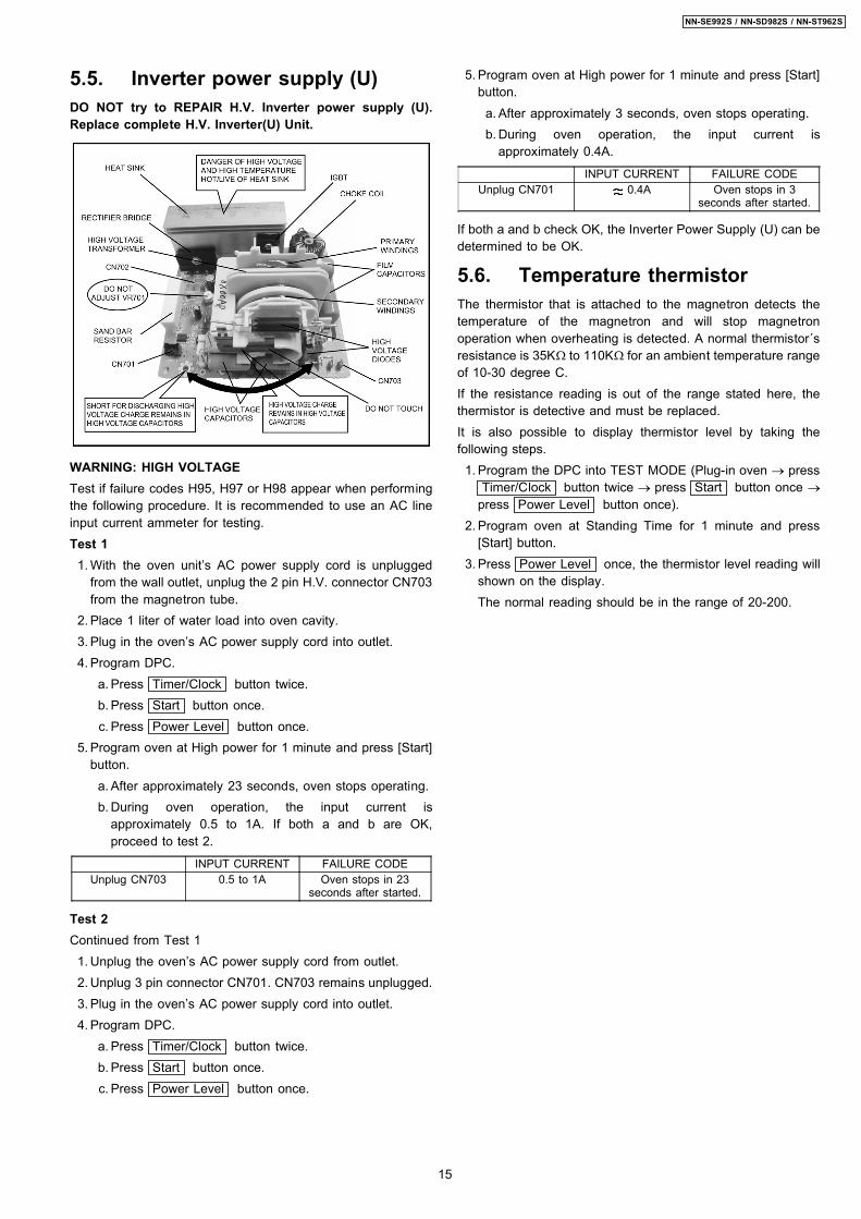
5.5. Inverter power supply (U)DO NOT try to REPAIR H.V. Inverter power supply (U).Replace complete H.V. Inverter(U) Unit.
WARNING: HIGH VOLTAGETest if failure codes H95, H97 or H98 appear when performingthe following procedure. It is recommended to use an AC lineinput current ammeter for testing.Test 1 1. With the oven unit’s AC power supply cord is unplugged
from the wall outlet, unplug the 2 pin H.V. connector CN703from the magnetron tube.
2. Place 1 liter of water load into oven cavity. 3. Plug in the oven’s AC power supply cord into outlet. 4. Program DPC.
a. Press Timer/Clock button twice. b. Press Start button once. c. Press Power Level button once.
5. Program oven at High power for 1 minute and press [Start]button. a. After approximately 23 seconds, oven stops operating. b. During oven operation, the input current is
approximately 0.5 to 1A. If both a and b are OK,proceed to test 2.
INPUT CURRENT FAILURE CODEUnplug CN703 0.5 to 1A Oven stops in 23
seconds after started.
Test 2Continued from Test 1 1. Unplug the oven’s AC power supply cord from outlet. 2. Unplug 3 pin connector CN701. CN703 remains unplugged. 3. Plug in the oven’s AC power supply cord into outlet. 4. Program DPC.
a. Press Timer/Clock button twice. b. Press Start button once. c. Press Power Level button once.
5. Program oven at High power for 1 minute and press [Start]button. a. After approximately 3 seconds, oven stops operating. b. During oven operation, the input current is
approximately 0.4A.
INPUT CURRENT FAILURE CODEUnplug CN701 0.4A Oven stops in 3
seconds after started.
If both a and b check OK, the Inverter Power Supply (U) can bedetermined to be OK.
5.6. Temperature thermistorThe thermistor that is attached to the magnetron detects thetemperature of the magnetron and will stop magnetronoperation when overheating is detected. A normal thermistor´sresistance is 35KΩ to 110KΩ for an ambient temperature rangeof 10-30 degree C.If the resistance reading is out of the range stated here, thethermistor is detective and must be replaced.It is also possible to display thermistor level by taking thefollowing steps. 1. Program the DPC into TEST MODE (Plug-in oven → press
Timer/Clock button twice → press Start button once →
press Power Level button once). 2. Program oven at Standing Time for 1 minute and press
[Start] button. 3. Press Power Level once, the thermistor level reading will
shown on the display.The normal reading should be in the range of 20-200.
15
NN-SE992S / NN-SD982S / NN-ST962S

6.1. Adjustment of primaryinterlock switch, secondaryinterlock switch and monitorswitch.
1. Mount the Primary Interlock Switch, the Secondary InterlockSwitch and the Monitor Switch to the door hook assemblyas shown in illustration.NOTE:
No specific individual adjustments duringinstallation of the Primary Interlock Switch,Secondary Interlock Switch or Monitor Switch to thedoor hook are required.
2. When mounting the door hook assembly to the ovenassembly, adjust the door hook assembly by moving it inthe direction of the arrows in the illustration so that the ovendoor will not have any play in it. Check for play in the doorby pulling the door assembly. Make sure that the latch keysmove smoothly after adjustment is completed. Completelytighten the screws holding the door hook assembly to theoven assembly.
3. Reconnect the monitor switch and check the continuity ofthe monitor circuit and all interlock switches again byfollowing the component test procedures.
6.2. Measurement of microwaveoutput
The output power of the magnetron can be determined byperforming IEC standard test procedures. However, due to thecomplexity of IEC test procedures, it is recommended to testthe magnetron using the simple method outlined below.Necessary Equipment:*1 liter beaker *Glass thermometer*Wrist watch or stopwatchNOTE:
Check the line voltage under load. Low voltage willlower the magnetron output. Take the temperaturereadings and heating time as accurately as possible.
1. Fill the beaker with exactly one liter of tap water. Stir thewater using the thermometer and record the water’stemperature. (recorded as T1).
2. Place the beaker on the center of glass tray.Set the oven for High power and heat it for exactly oneminute.
3. Stir the water again and read the temperature of the water.(recorded as T2).
4. The normal temperature rise at High power level for eachmodel is as shown in table.
TABLE (1L-1min. test)RATED OUTPUT TEMPERATURE RISE
1200W Min. 18.5°F(10.3°C)
6 MEASUREMENTS AND ADJUSTMENTS
16
NN-SE992S / NN-SD982S / NN-ST962S
7.1. Equipment • Electromagnatic radiation monitor • Glass thermometer 212°F or 100°C • 600cc glass beaker
7.2. Procedure for measuringradiation leakage
Note before measuring: • Do not exceed meter full scale deflection. Leakage monitor
should initially be set to the highest scale. • To prevent false readings, the test probe should be held by
the grip portion of the handle only and moved along theshaded area in Figure no faster than 1 inch/sec(2.5cm/sec).
• Leakage with the outer panel removed: less than 5mW/cm2. • Leakage for a fully assembled oven with door normally
closed: less than 2mW/cm 2. • Leakage for a fully assembled oven [Before the latch switch
(primary) is interrupted] while pulling the door: less than2mW/cm 2.
1. Pour 275 ± 15cc (9ozss± 1/2oz) of 20°C ± 5°C (68° ± 9°F)water in a beaker which is graduated to 600cc, and place inthe center of the oven.
2. Set the radiation monitor to 2450MHz and use it followingthe manufacturer´s recommended test procedure to assurecorrect results.
3. When measuring the leakage, always use the 2 inch (5cm)spacer supplied with the probe.
4. Tap the start button or set the timer and with the magnetronoscillating, measure the leakage by holding the probeperpendicular to the surface being measured.
7.2.1. Measurement with the outer panelremoved.
Whenever you replace the magnetron, measure for radiationleakage before the outer panel is installed and after allnecessary components are replaced or adjusted. Special careshould be taken in measuring around the magnetron.
7.2.2. Measurements with a fullyassembled oven.
After all components, including outer panel are fully assembled,measure for radiation leakage around the door periphery, thedoor viewing window, the exhaust opening, control panel andair inlet openings.
7.3. Record keeping andnotification after measurement
• After any adjustment or repair to a microwave oven, aleakage reading must be taken. Record this leakagereading on the repair ticket even if it is zero.A copy of this repair ticket and the microwave leakagereading should be kept by repair facility.
• Should the radiation leakage be more than 2 mW/cm2 afterdetermining that all parts are in good condition, functioningproperly, and genuine replacement parts as listed in thismanual have been used.
7 PROCEDURE FOR MEASURING MICROWAVE ENERGYLEAKAGE
17
NN-SE992S / NN-SD982S / NN-ST962S
8 TROUBLESHOOTING GUIDEDANGER: HIGH VOLTAGES
1. DO NOT RE-ADJUST PRESET CONTROL on the H.V.Inverter (U). It is very dangerous to repair or adjust without proper test equipmentbecause this circuit generates very large current and high voltage. Operating a misaligned inverter circuit is dangerous.
2. Ensure proper grounding before troubleshooting.3. Be careful of the high voltage circuitry, taking necessary precautions when troubleshooting.4. Discharge high voltage remaining in the H.V.Inverter (U).5. When checking the continuity of the switches or the H.V.Inverter, disconnect one lead wire from these parts and then check continuity with the
AC plug removed. Doing otherwise may result in a false reading or damage to your meter. When disconnecting a plastic connector from aterminal, you must hold the plastic connector instead of the lead wire and then disconnect it, otherwise lead wire may be damaged or theconnector cannot be removed.
6. Do not touch any parts of the circuitry on the digital programmer circuit, since static electric discharge may damage this control panel. Alwaystouch ground while working on this panel to discharge any static charge in your body.
7. 120V AC is present on the digital programmer circuit (Terminals of power relay’s and primary circuit of Digital Programmer Circuit). Whentroubleshooting, be cautious of possible electrical shock hazard.
Before troubleshooting, operate the microwave oven following the correct operating procedures in the instruction manual in orderto find the exact cause of any trouble, since operator error may be mistaken for the oven’s malfunction.
H97 & H98 error code displayIf 3 times H97 or 2 times H98 exist, microwave oven can not be used any more, even if the defective parts already be replaced &un-plug and plug-in again.How to reset for the service:
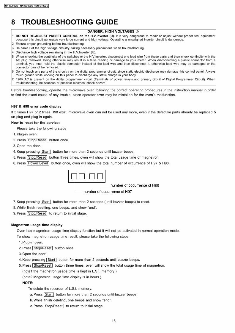
Please take the following steps 1. Plug-in oven. 2. Press Stop/Reset button once. 3. Open the door. 4. Keep pressing Start button for more than 2 seconds until buzzer beeps. 5. Press Stop/Reset button three times, oven will show the total usage time of magnetron. 6. Press Power Level button once, oven will show the total number of occurrence of H97 & H98.
7. Keep pressing Start button for more than 2 seconds (until buzzer beeps) to reset. 8. While finish resetting, one beeps, and show “end”. 9. Press Stop/Reset to return to initial stage.
Magnetron usage time displayOven has magnetron usage time display function but it will not be activated in normal operation mode.To show magnetron usage time result, please take the following steps: 1. Plug-in oven. 2. Press Stop/Reset button once. 3. Open the door. 4. Keep pressing Start button for more than 2 seconds until buzzer beeps. 5. Press Stop/Reset button three times, oven will show the total usage time of magnetron.
(note1:the magnetron usage time is kept in L.S.I. memory.)(note2:Magnetron usage time display is in hours.)NOTE:
To delete the recorder of L.S.I. memory. a. Press Start button for more than 2 seconds until buzzer beeps. b. While finish deleting, one beeps and show “end”. c. Press Stop/Reset to return to initial stage.
18
NN-SE992S / NN-SD982S / NN-ST962S
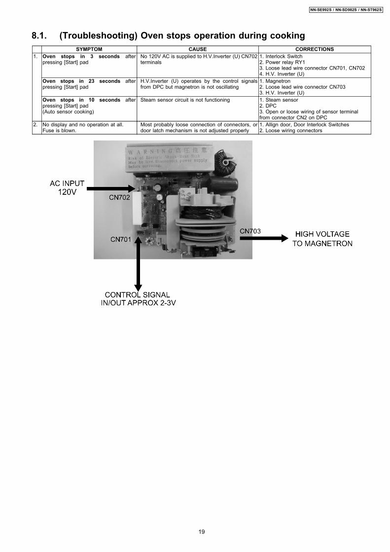
8.1. (Troubleshooting) Oven stops operation during cookingSYMPTOM CAUSE CORRECTIONS
1. Oven stops in 3 seconds afterpressing [Start] pad
No 120V AC is supplied to H.V.Inverter (U) CN702terminals
1. Interlock Switch2. Power relay RY13. Loose lead wire connector CN701, CN7024. H.V. Inverter (U)
Oven stops in 23 seconds afterpressing [Start] pad
H.V.Inverter (U) operates by the control signalsfrom DPC but magnetron is not oscillating
1. Magnetron2. Loose lead wire connector CN7033. H.V. Inverter (U)
Oven stops in 10 seconds afterpressing [Start] pad(Auto sensor cooking)
Steam sensor circuit is not functioning 1. Steam sensor2. DPC3. Open or loose wiring of sensor terminalfrom connector CN2 on DPC
2. No display and no operation at all.Fuse is blown.
Most probably loose connection of connectors, ordoor latch mechanism is not adjusted properly
1. Allign door, Door Interlock Switches2. Loose wiring connectors
19
NN-SE992S / NN-SD982S / NN-ST962S
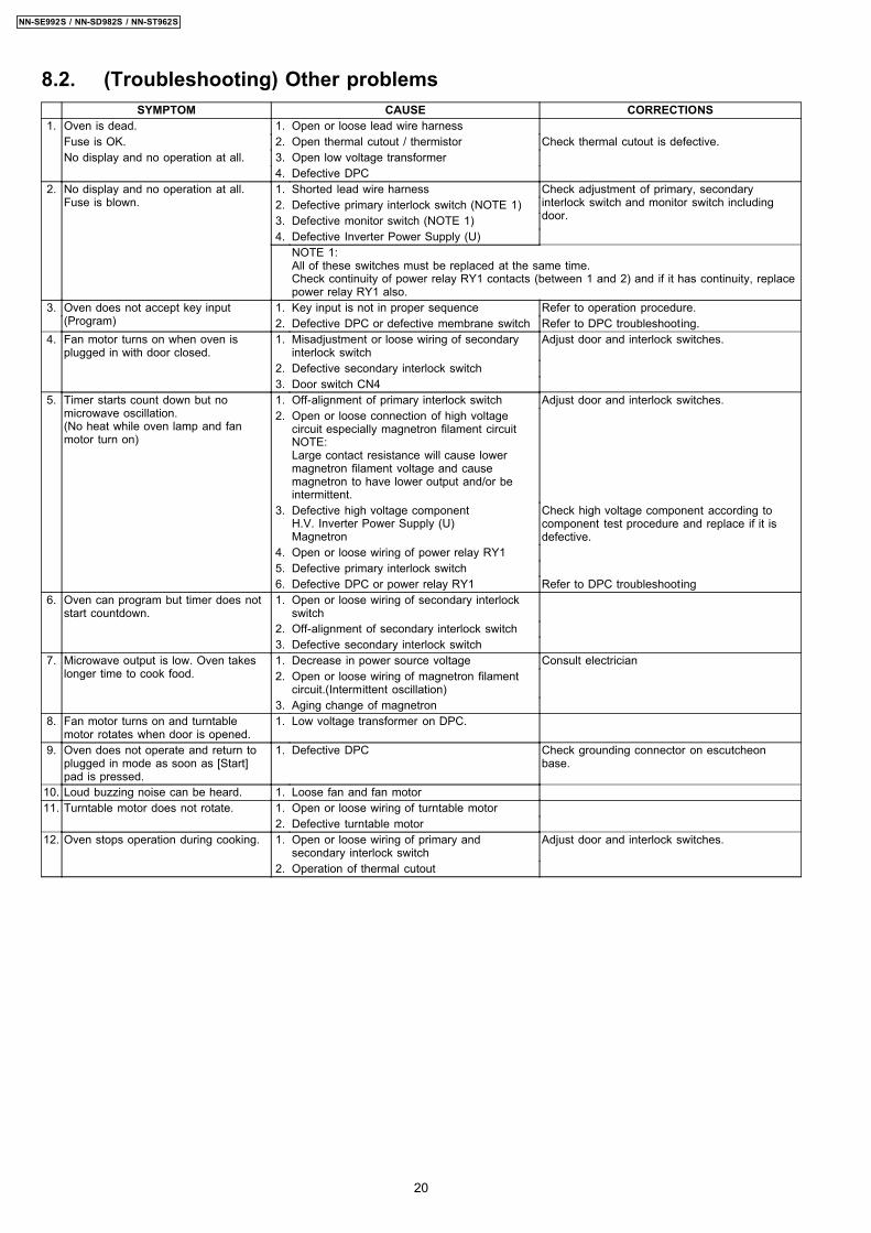
8.2. (Troubleshooting) Other problemsSYMPTOM CAUSE CORRECTIONS
1. Oven is dead. 1. Open or loose lead wire harnessFuse is OK. 2. Open thermal cutout / thermistor Check thermal cutout is defective.No display and no operation at all. 3. Open low voltage transformer
4. Defective DPC2. No display and no operation at all.
Fuse is blown.1. Shorted lead wire harness Check adjustment of primary, secondary
interlock switch and monitor switch includingdoor.
2. Defective primary interlock switch (NOTE 1)3. Defective monitor switch (NOTE 1)4. Defective Inverter Power Supply (U)
NOTE 1:All of these switches must be replaced at the same time.Check continuity of power relay RY1 contacts (between 1 and 2) and if it has continuity, replacepower relay RY1 also.
3. Oven does not accept key input(Program)
1. Key input is not in proper sequence Refer to operation procedure.2. Defective DPC or defective membrane switch Refer to DPC troubleshooting.
4. Fan motor turns on when oven isplugged in with door closed.
1. Misadjustment or loose wiring of secondaryinterlock switch
Adjust door and interlock switches.
2. Defective secondary interlock switch3. Door switch CN4
5. Timer starts count down but nomicrowave oscillation.(No heat while oven lamp and fanmotor turn on)
1. Off-alignment of primary interlock switch Adjust door and interlock switches.2. Open or loose connection of high voltage
circuit especially magnetron filament circuitNOTE:Large contact resistance will cause lowermagnetron filament voltage and causemagnetron to have lower output and/or beintermittent.
3. Defective high voltage componentH.V. Inverter Power Supply (U)Magnetron
Check high voltage component according tocomponent test procedure and replace if it isdefective.
4. Open or loose wiring of power relay RY15. Defective primary interlock switch6. Defective DPC or power relay RY1 Refer to DPC troubleshooting
6. Oven can program but timer does notstart countdown.
1. Open or loose wiring of secondary interlockswitch
2. Off-alignment of secondary interlock switch3. Defective secondary interlock switch
7. Microwave output is low. Oven takeslonger time to cook food.
1. Decrease in power source voltage Consult electrician2. Open or loose wiring of magnetron filament
circuit.(Intermittent oscillation)3. Aging change of magnetron
8. Fan motor turns on and turntablemotor rotates when door is opened.
1. Low voltage transformer on DPC.
9. Oven does not operate and return toplugged in mode as soon as [Start]pad is pressed.
1. Defective DPC Check grounding connector on escutcheonbase.
10. Loud buzzing noise can be heard. 1. Loose fan and fan motor11. Turntable motor does not rotate. 1. Open or loose wiring of turntable motor
2. Defective turntable motor12. Oven stops operation during cooking. 1. Open or loose wiring of primary and
secondary interlock switchAdjust door and interlock switches.
2. Operation of thermal cutout
20
NN-SE992S / NN-SD982S / NN-ST962S

8.3. Troubleshooting of inverter circuit (U) and magnetronThis oven is programmed with a self diagnostics failure code system which will help for troubleshooting. H95, H97, H98 and H99are the provided failure codes to indicate magnetron and inverter circuit problem areas. This section explains failure codes of H95,H97, H98 and H99. First, you must program the DPC into TEST MODE, press Timer/Clock button twice → press Start buttononce → press Power Level button once. Program unit for operation. H95, H97, H98, H99 appears in display window a short timeafter [Start] pad is pressed and there is no microwave oscillation.
Alternate way to troubleshoot oven with AC Ampere meter used
H95, H97, H98, H99 appears in display window a short time after [Start] pad is pressed and no microwave oscillation with ACAmpere meter used for troubleshooting.
21
NN-SE992S / NN-SD982S / NN-ST962S

8.4. Trouble related to Digital Programmer Circuit8.4.1. NN-SE992S
SYMPTOM STEP CHECK RESULT CAUSE/CORRECTIONSNo display when oven is first pluggedin
1 Fuse pattern of D.P.C. Normal →Step2
Open Replace D.P.C. or Fuse Pattern2 Low voltage transforment (L.V.T.)
secondary voltageAbnormal 0V L.V.T.Normal →Step3
3 IC1 pin 9 voltage Abnormal IC10, ZD10Normal=5V IC1, Display
No key input 1 Touch switch continuity Abnormal Touch switchNormal IC1
No beep sound 1 IC1 pin 5 voltage Abnormal IC1Normal=5V BZ210, Q210
No microwave oscillation at anypower
1 IC1 pin 27 voltages while operation at highpower
Abnormal IC1Normal=5V →Step2
2 Collector of Q223 voltage Abnormal Q223 and/or Q225, Q226, Q227Normal 0.7V →Step3
3 Short circuit between collector of Q223and emitter of Q225
Still not turn on RY1RY1 turns on Q223 and/or Q225, Q226, Q227
Dark or unclear display 1 Replace display and check operation Normal DisplayAbnormal IC1
Missing or lighting of unnecessarysegment
1 Replace IC1 and check operation Normal IC1Abnormal Display
H95/H97/H98 appears in window andoven stops operation.Program Highpower for 1 minute and conductfollowing test quickly, unlessH95/H97/H98 appears and ovenstops
1 Unplug CN702 (2 pin) connector andmeasure voltage between terminals
Abnormal=0V 1. Interlock Switch2. D.P.C. /Power Relay
Normal=120V →Step22 Unplug CN701 (3 pin) connector and
measure pin1 voltage of D. P. C. CN3Abnormal=0V D.P.C.Approx. AC 3V Magnetron
22
NN-SE992S / NN-SD982S / NN-ST962S
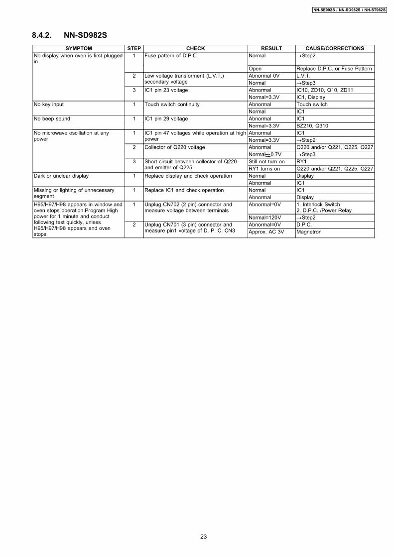
8.4.2. NN-SD982SSYMPTOM STEP CHECK RESULT CAUSE/CORRECTIONS
No display when oven is first pluggedin
1 Fuse pattern of D.P.C. Normal →Step2
Open Replace D.P.C. or Fuse Pattern2 Low voltage transforment (L.V.T.)
secondary voltageAbnormal 0V L.V.T.Normal →Step3
3 IC1 pin 23 voltage Abnormal IC10, ZD10, Q10, ZD11Normal=3.3V IC1, Display
No key input 1 Touch switch continuity Abnormal Touch switchNormal IC1
No beep sound 1 IC1 pin 29 voltage Abnormal IC1Normal=3.3V BZ210, Q310
No microwave oscillation at anypower
1 IC1 pin 47 voltages while operation at highpower
Abnormal IC1Normal=3.3V →Step2
2 Collector of Q220 voltage Abnormal Q220 and/or Q221, Q225, Q227Normal 0.7V →Step3
3 Short circuit between collector of Q220and emitter of Q225
Still not turn on RY1RY1 turns on Q220 and/or Q221, Q225, Q227
Dark or unclear display 1 Replace display and check operation Normal DisplayAbnormal IC1
Missing or lighting of unnecessarysegment
1 Replace IC1 and check operation Normal IC1Abnormal Display
H95/H97/H98 appears in window andoven stops operation.Program Highpower for 1 minute and conductfollowing test quickly, unlessH95/H97/H98 appears and ovenstops
1 Unplug CN702 (2 pin) connector andmeasure voltage between terminals
Abnormal=0V 1. Interlock Switch2. D.P.C. /Power Relay
Normal=120V →Step22 Unplug CN701 (3 pin) connector and
measure pin1 voltage of D. P. C. CN3Abnormal=0V D.P.C.Approx. AC 3V Magnetron
23
NN-SE992S / NN-SD982S / NN-ST962S
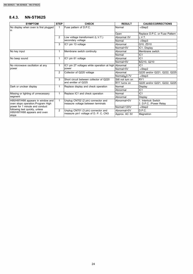
8.4.3. NN-ST962SSYMPTOM STEP CHECK RESULT CAUSE/CORRECTIONS
No display when oven is first pluggedin
1 Fuse pattern of D.P.C. Normal →Step2
Open Replace D.P.C. or Fuse Pattern2 Low voltage transforment (L.V.T.)
secondary voltageAbnormal 0V L.V.T.Normal →Step3
3 IC1 pin 13 voltage Abnormal Q10, ZD10Normal=5V IC1, Display
No key input 1 Membrane switch continuity Abnormal Membrane switchNormal IC1
No beep sound 1 IC1 pin 61 voltage Abnormal IC1Normal=5V BZ210, Q210
No microwave oscillation at anypower
1 IC1 pin 27 voltages while operation at highpower
Abnormal IC1Normal=5V →Step2
2 Collector of Q220 voltage Abnormal Q220 and/or Q221, Q222, Q225Normal 0.7V →Step3
3 Short circuit between collector of Q220and emitter of Q225
Still not turn on RY1RY1 turns on Q220 and/or Q221, Q222, Q225
Dark or unclear display 1 Replace display and check operation Normal DisplayAbnormal IC1
Missing or lighting of unnecessarysegment
1 Replace IC1 and check operation Normal IC1Abnormal Display
H95/H97/H98 appears in window andoven stops operation.Program Highpower for 1 minute and conductfollowing test quickly, unlessH95/H97/H98 appears and ovenstops
1 Unplug CN702 (2 pin) connector andmeasure voltage between terminals
Abnormal=0V 1. Interlock Switch2. D.P.C. /Power Relay
Normal=120V →Step22 Unplug CN701 (3 pin) connector and
measure pin1 voltage of D. P. C. CN3Abnormal=0V D.P.C.Approx. AC 3V Magnetron
24
NN-SE992S / NN-SD982S / NN-ST962S
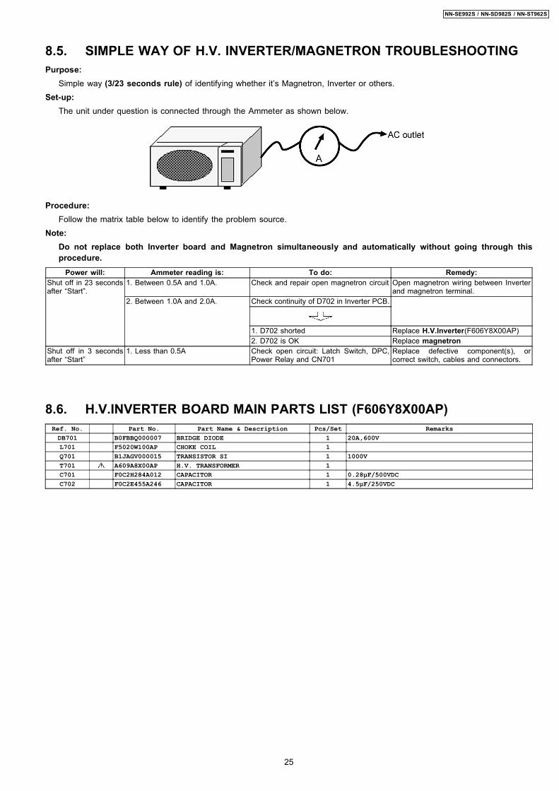
8.5. SIMPLE WAY OF H.V. INVERTER/MAGNETRON TROUBLESHOOTINGPurpose:
Simple way (3/23 seconds rule) of identifying whether it’s Magnetron, Inverter or others.Set-up:
The unit under question is connected through the Ammeter as shown below.
Procedure:Follow the matrix table below to identify the problem source.
Note:Do not replace both Inverter board and Magnetron simultaneously and automatically without going through thisprocedure.
Power will: Ammeter reading is: To do: Remedy:Shut off in 23 secondsafter “Start”.
1. Between 0.5A and 1.0A. Check and repair open magnetron circuit Open magnetron wiring between Inverterand magnetron terminal.
2. Between 1.0A and 2.0A. Check continuity of D702 in Inverter PCB.
1. D702 shorted Replace H.V.Inverter(F606Y8X00AP)2. D702 is OK Replace magnetron
Shut off in 3 secondsafter “Start”
1. Less than 0.5A Check open circuit: Latch Switch, DPC,Power Relay and CN701
Replace defective component(s), orcorrect switch, cables and connectors.
8.6. H.V.INVERTER BOARD MAIN PARTS LIST (F606Y8X00AP)Ref. No. Part No. Part Name & Description Pcs/Set RemarksDB701 B0FBBQ000007 BRIDGE DIODE 1 20A,600VL701 F5020W100AP CHOKE COIL 1Q701 B1JAGV000015 TRANSISTOR SI 1 1000VT701 A609A8X00AP H.V. TRANSFORMER 1C701 F0C2H284A012 CAPACITOR 1 0.28µF/500VDCC702 F0C2E455A246 CAPACITOR 1 4.5µF/250VDC
25
NN-SE992S / NN-SD982S / NN-ST962S

8.7. How to check the semiconductors using an OHM meter
26
NN-SE992S / NN-SD982S / NN-ST962S
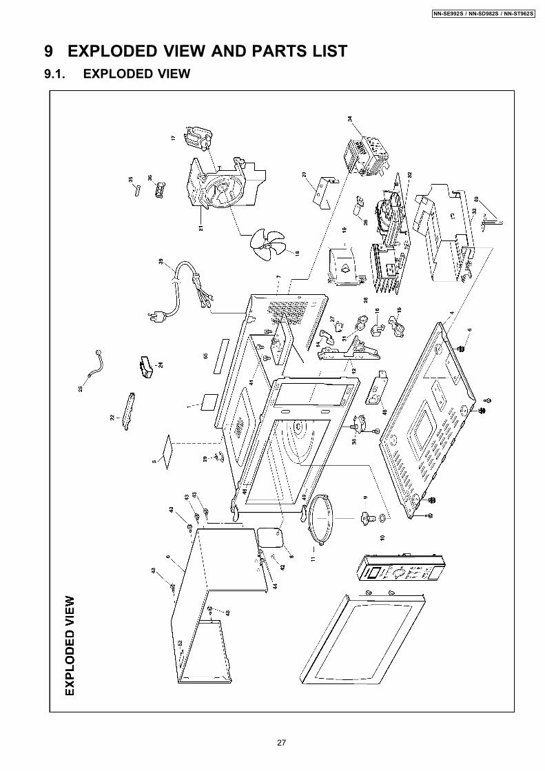
9 EXPLODED VIEW AND PARTS LIST9.1. EXPLODED VIEW
27
NN-SE992S / NN-SD982S / NN-ST962S
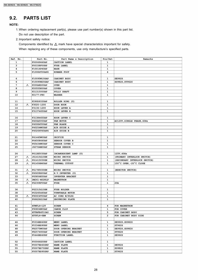
9.2. PARTS LISTNOTE:
1. When ordering replacement part(s), please use part number(s) shown in this part list.Do not use description of the part.
2. Important safety notice:Components identified by mark have special characteristics important for safety.When replacing any of these components, use only manufacture’s specified parts.
Ref. No. Part No. Part Name & Description Pcs/Set Remarks1 F00069660AP CAUTION LABEL 13 F00338F00RP FUSE LABEL 14 F10016P40AP BASE 15 F10084T00APS RUBBER FOOT 4
6 F10095W10SAP CABINET BODY 1 SE992S6 F10095W20SAP CABINET BODY 1 SD982S,ST962S7 F200A8D00AP OVEN 18 F20555K00AP COVER 19 F21315Y00AP PULLY SHAFT 110 F2177-F80 WASHER 1
11 F290D9330AP ROLLER RING (U) 112 F3020-1200 DOOR HOOK 114 F3136-1200 HOOK LEVER A 115 F31374650AP HOOK LEVER B 1
16 F31384650AP HOOK LEVER C 117 F400A5Y00AP FAN MOTOR 1 AC120V,SINGLE PHASE,60Hz18 F40084T00AP FAN BLADE 119 F40254W00AP AIR GUIDE A 120 F40264T60APG AIR GUIDE B 1
21 F41445W00AP ORIFICE 122 F64508660AP SENSOR COVER B 124 F65434W00AP SENSOR COVER C 125 J607S4M00AP STEAM SENSOR 1
26 F612E5Y30AP INCANDESCENT LAMP (U) 1 125V,60Hz27 J61415G10XN MICRO SWITCH 1 (PRIMARY INTERLOCK SWITCH)28 F61415U30XN MICRO SWITCH 1 (SECONDARY INTERLOCK SWITCH)29 F61456N60AP THERMAL CUTOUT 1 150°C OPEN,-20°C CLOSE
31 F61785U30XN MICRO SWITCH 1 (MONITOR SWITCH)32 F606Y8X00AP H.V.INVERTER (U) 133 F65856K50AP INVERTER BRACKET 134 2M261-M32KLP MAGNETRON 135 F62308F00AP FUSE 1 20A
36 F62315G10XN FUSE HOLDER 138 F63265G60AP TURNTABLE MOTOR 139 F900C4T00AP AC CORD W/PLUG 140 F66626G10AP GROUNDING PLATE 1
41 XTWFL4+12T SCREW 4 FOR MAGNETRON42 F90804W00AP CANOE CLIP 1 FOR COVER43 XTTBFE4T10A0 SCREW 5 FOR CABINET BODY44 XTTFL4+6BN SCREW 2 FOR CABINET BODY SIDE
46 F0334BD60RP MENU LABEL 1 SE992S,SD982S46 F0334BD90RP MENU LABEL 1 ST962S48 F82575W00AP DOOR OPENING BRACKET 1 SE992S,SD982S48 F82574U00AP DOOR OPENING BRACKET 1 ST962S49 F0446BD60RP FUNCTION LABEL 1 SE992S
52 F00066G00RP CAUTION LABEL 155 F0007BD60SRP NAME PLATE 1 SE992S55 F0007BD70SRP NAME PLATE 1 SD982S55 F0007BD90SRP NAME PLATE 1 ST962S
28
NN-SE992S / NN-SD982S / NN-ST962S
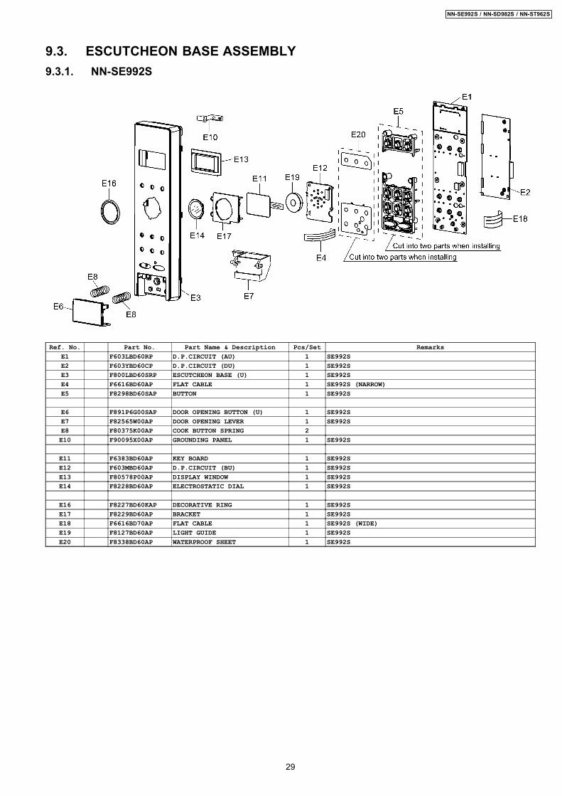
9.3. ESCUTCHEON BASE ASSEMBLY9.3.1. NN-SE992S
Ref. No. Part No. Part Name & Description Pcs/Set RemarksE1 F603LBD60RP D.P.CIRCUIT (AU) 1 SE992SE2 F603YBD60CP D.P.CIRCUIT (DU) 1 SE992SE3 F800LBD60SRP ESCUTCHEON BASE (U) 1 SE992SE4 F6616BD60AP FLAT CABLE 1 SE992S (NARROW)E5 F8298BD60SAP BUTTON 1 SE992S
E6 F891P6G00SAP DOOR OPENING BUTTON (U) 1 SE992SE7 F82565W00AP DOOR OPENING LEVER 1 SE992SE8 F80375K00AP COOK BUTTON SPRING 2E10 F90095X00AP GROUNDING PANEL 1 SE992S
E11 F6383BD60AP KEY BOARD 1 SE992SE12 F603MBD60AP D.P.CIRCUIT (BU) 1 SE992SE13 F80578P00AP DISPLAY WINDOW 1 SE992SE14 F8228BD60AP ELECTROSTATIC DIAL 1 SE992S
E16 F8227BD60KAP DECORATIVE RING 1 SE992SE17 F8229BD60AP BRACKET 1 SE992SE18 F6616BD70AP FLAT CABLE 1 SE992S (WIDE)E19 F8127BD60AP LIGHT GUIDE 1 SE992SE20 F8338BD60AP WATERPROOF SHEET 1 SE992S
29
NN-SE992S / NN-SD982S / NN-ST962S
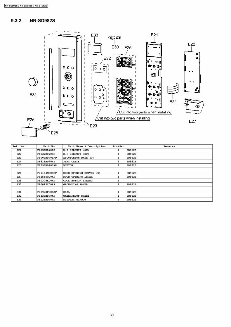
9.3.2. NN-SD982S
Ref. No. Part No. Part Name & Description Pcs/Set RemarksE21 F603LBD70RP D.P.CIRCUIT (AU) 1 SD982SE22 F603YBD70RP D.P.CIRCUIT (DU) 1 SD982SE23 F800LBD70SRP ESCUTCHEON BASE (U) 1 SD982SE24 F6616BD70AP FLAT CABLE 1 SD982SE25 F8298BD70SAP BUTTON 1 SD982S
E26 F891P4M60SCP DOOR OPENING BUTTON (U) 1 SD982SE27 F82565W00AP DOOR OPENING LEVER 1 SD982SE28 F80375K00AP COOK BUTTON SPRING 1E30 F90095X00AP GROUNDING PANEL 1 SD982S
E31 F83928P00KAP DIAL 1 SD982SE32 F8338BD70AP WATERPROOF SHEET 1 SD982SE33 F8126BD70RP DISPLAY WINDOW 1 SD982S
30
NN-SE992S / NN-SD982S / NN-ST962S
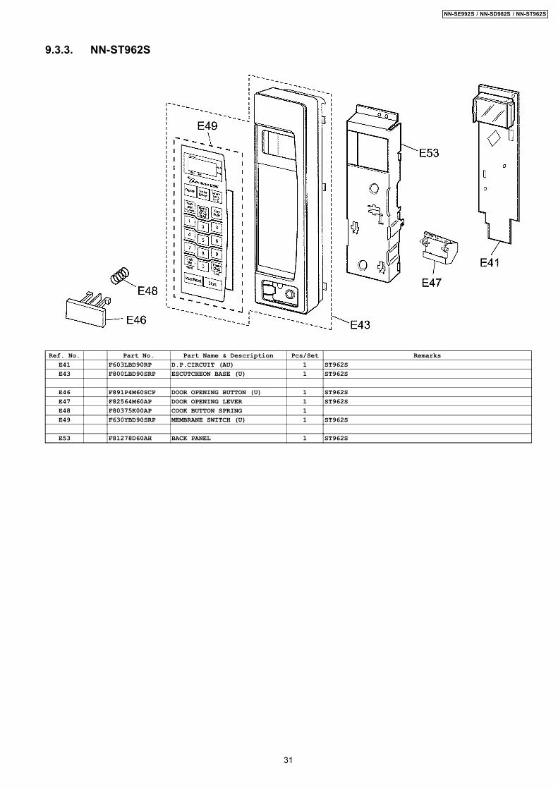
9.3.3. NN-ST962S
Ref. No. Part No. Part Name & Description Pcs/Set RemarksE41 F603LBD90RP D.P.CIRCUIT (AU) 1 ST962SE43 F800LBD90SRP ESCUTCHEON BASE (U) 1 ST962S
E46 F891P4M60SCP DOOR OPENING BUTTON (U) 1 ST962SE47 F82564M60AP DOOR OPENING LEVER 1 ST962SE48 F80375K00AP COOK BUTTON SPRING 1E49 F630YBD90SRP MEMBRANE SWITCH (U) 1 ST962S
E53 F81278D60AH BACK PANEL 1 ST962S
31
NN-SE992S / NN-SD982S / NN-ST962S
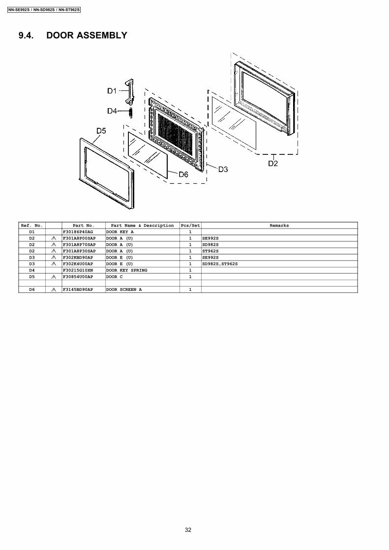
9.4. DOOR ASSEMBLY
Ref. No. Part No. Part Name & Description Pcs/Set RemarksD1 F30186P40AG DOOR KEY A 1D2 F301A8P00SAP DOOR A (U) 1 SE992SD2 F301A8P70SAP DOOR A (U) 1 SD982SD2 F301A8P30SAP DOOR A (U) 1 ST962SD3 F302KBD90AP DOOR E (U) 1 SE992SD3 F302K4U00AP DOOR E (U) 1 SD982S,ST962SD4 F30215G10XN DOOR KEY SPRING 1D5 F30854U00AP DOOR C 1
D6 F3145BD90AP DOOR SCREEN A 1
32
NN-SE992S / NN-SD982S / NN-ST962S

9.5. WIRING MATERIALS
Ref. No. Part No. Part Name & Description Pcs/Set RemarksW1 F030ABD60RP LEAD WIRE HARNESS 1W2 F030E8W50AP H.V.LEAD WIRE 1W3 F03537B70AP LEAD WIRE HARNESS (U) 1 (INCLUDING THERMISTOR)
33
NN-SE992S / NN-SD982S / NN-ST962S
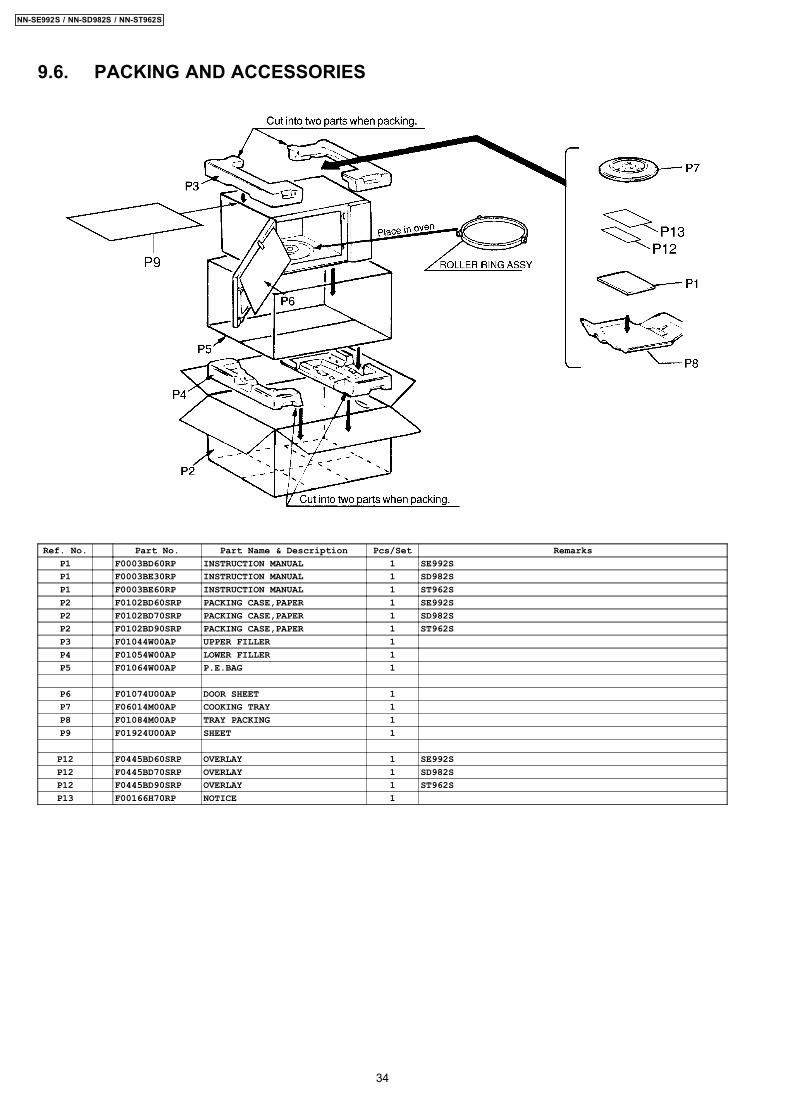
9.6. PACKING AND ACCESSORIES
Ref. No. Part No. Part Name & Description Pcs/Set RemarksP1 F0003BD60RP INSTRUCTION MANUAL 1 SE992SP1 F0003BE30RP INSTRUCTION MANUAL 1 SD982SP1 F0003BE60RP INSTRUCTION MANUAL 1 ST962SP2 F0102BD60SRP PACKING CASE,PAPER 1 SE992SP2 F0102BD70SRP PACKING CASE,PAPER 1 SD982SP2 F0102BD90SRP PACKING CASE,PAPER 1 ST962SP3 F01044W00AP UPPER FILLER 1P4 F01054W00AP LOWER FILLER 1P5 F01064W00AP P.E.BAG 1
P6 F01074U00AP DOOR SHEET 1P7 F06014M00AP COOKING TRAY 1P8 F01084M00AP TRAY PACKING 1P9 F01924U00AP SHEET 1
P12 F0445BD60SRP OVERLAY 1 SE992SP12 F0445BD70SRP OVERLAY 1 SD982SP12 F0445BD90SRP OVERLAY 1 ST962SP13 F00166H70RP NOTICE 1
34
NN-SE992S / NN-SD982S / NN-ST962S

10 DIGITAL PROGRAMMER CIRCUIT10.1. SCHEMATIC DIAGRAM (NN-SE992S)
35
NN-SE992S / NN-SD982S / NN-ST962S
36
NN-SE992S / NN-SD982S / NN-ST962S

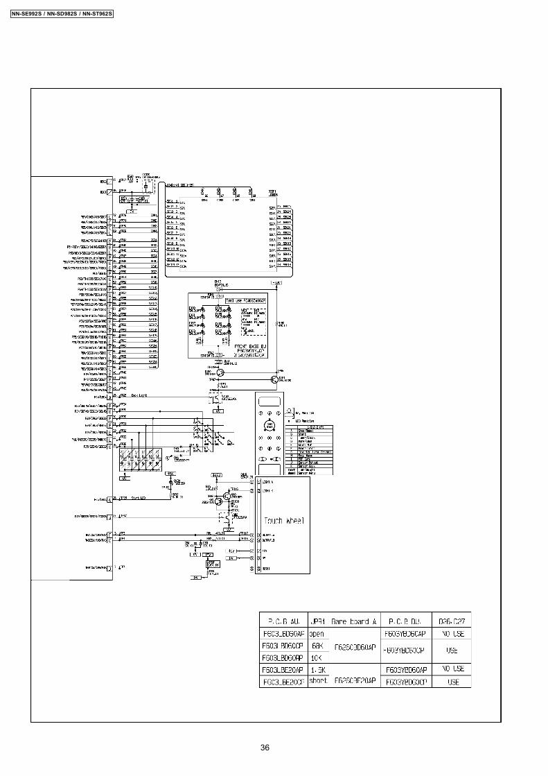
10.2. SCHEMATIC DIAGRAM (NN-SD982S)
37
NN-SE992S / NN-SD982S / NN-ST962S
38
NN-SE992S / NN-SD982S / NN-ST962S
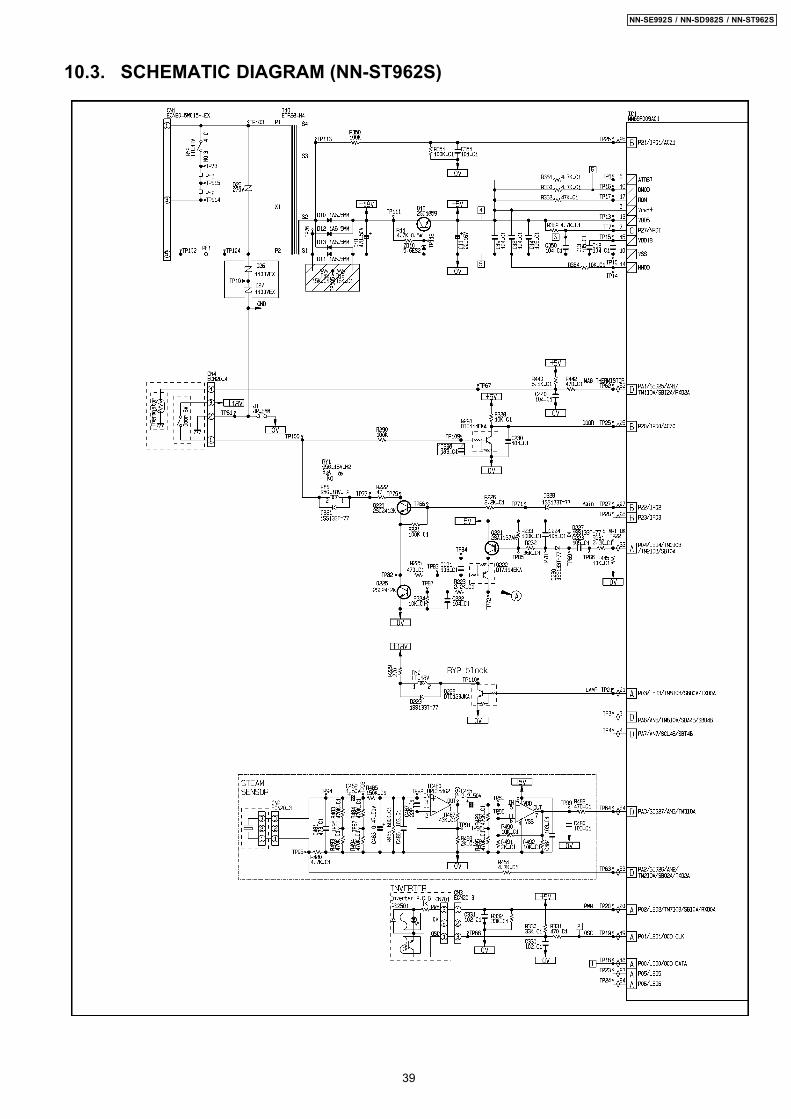
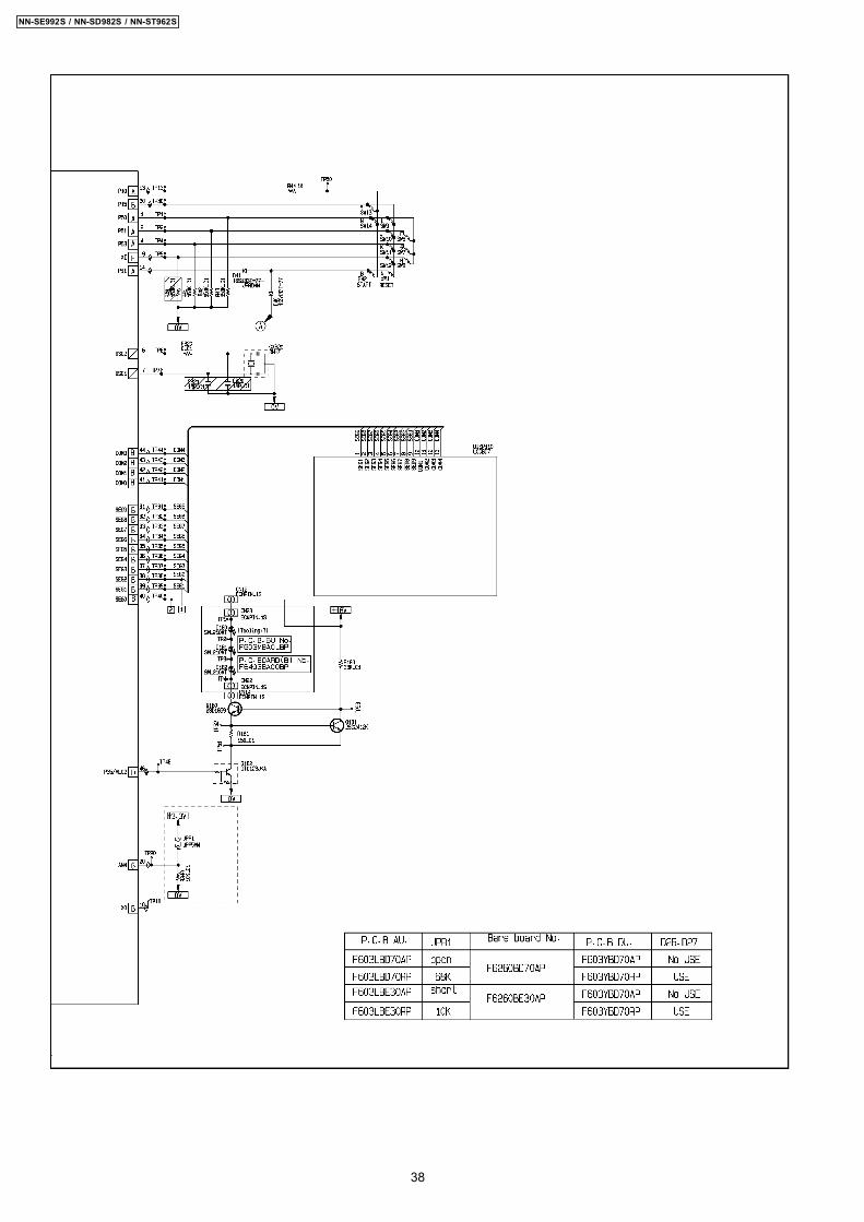
10.3. SCHEMATIC DIAGRAM (NN-ST962S)
39
NN-SE992S / NN-SD982S / NN-ST962S

40
NN-SE992S / NN-SD982S / NN-ST962S
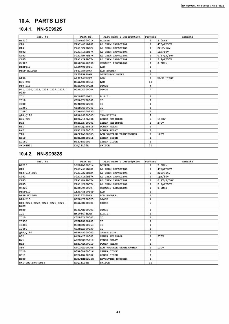
10.4. PARTS LIST10.4.1. NN-SE992S
Ref. No. Part No. Part Name & Description Pcs/Set RemarksBZ210 L0DDEA000014 BUZZER 1 2.0KHzC10 F2A1V471B281 AL CHEM CAPACITOR 1 470µF/35VC14 F2A1C220B624 AL CHEM CAPACITOR 1 22µF/16VC482 F2A1H1R0B574 AL CHEM CAPACITOR 1 1µF/50VC483 F2A1HR47B574 AL CHEM CAPACITOR 1 0.47µF/50VC485 F2A1H2R2B574 AL CHEM CAPACITOR 1 2.2µF/50VCX320 H2A8004A0038 CERAMIC RESONATOR 1 8.0MHzDISP110 L5AYAYY00167 LCD 1DISP HOLDER F66175W00AP LCD HOLDER 1
F67525E40XN DIFFUSION SHEET 1D130 AE3294UBCA7 LED 1 BLUE LIGHTD81-D90 B3AAB0000354 LED 10D10-D13 B0EAKT000025 DIODE 4D41,D220,D222,D223,D227,D229,D230
B0AACK000004 DIODE 7
IC1 MN101E31DAZ L.S.I. 1IC10 C0DAGYY00041 IC 1IC80 C0ZBZ0002004 IC 1IC380 C3EBDC000063 IC 1IC480 C0ABBA000230 IC 1Q10,Q180 B1BAAJ000003 TRANSISTOR 2D26,D27 D4EAY112A036 ZENER RESISTOR 2 1100VD32 D4EAY2710001 ZENER RESISTOR 1 270VRY1 AEBGJQC25F18 POWER RELAY 1RY2 K6B1AZA00010 POWER RELAY 1T10 G4C2AAD00005 LOW VOLTAGE TRANSFORMER 1 120VZD10 B0BA5R600016 ZENER DIODE 1ZD180 DZ2J15000L ZENER DIODE 1SW1-SW11 EVQ11L05R SWITCH 11
10.4.2. NN-SD982SRef. No. Part No. Part Name & Description Pcs/Set Remarks
BZ210 L0DDEA000014 BUZZER 1 2.0KHzC10 F2A1V471B281 AL CHEM CAPACITOR 1 470µF/35VC13,C14,C16 F2A1C220B624 AL CHEM CAPACITOR 3 22µF/16VC482 F2A1H1R0B574 AL CHEM CAPACITOR 1 1µF/50VC483 F2A1HR47B574 AL CHEM CAPACITOR 1 0.47µF/50VC485 F2A1H2R2B574 AL CHEM CAPACITOR 1 2.2µF/50VCX320 H2B800400007 CERAMIC RESONATOR 1 8.0MHzDISP110 L5AYAYY00169 LCD 1DISP HOLDER F66177D60AP LCD HOLDER 1D10-D13 B0EAKT000025 DIODE 4D40,D220,D222,D223,D226,D227,D229
B0AACK000004 DIODE 7
D480 B0JAAE000001 DIODE 1IC1 MN101C78AAN L.S.I. 1IC10 C0DAGYY00041 IC 1IC350 C0EBE0000401 IC 1IC380 C3EBDC000063 IC 1IC480 C0ABBA000230 IC 1Q10,Q180 B1BAAJ000003 TRANSISTOR 2D32 D4EAY2710001 ZENER RESISTOR 1 270VRY1 AEBGJQC25F18 POWER RELAY 1RY2 K6B1AZA00010 POWER RELAY 1T10 G4C2AAD00005 LOW VOLTAGE TRANSFORMER 1 120VZD10 B0BA5R600016 ZENER DIODE 1ZD11 B0BA4R400002 ZENER DIODE 1RE80 EVEJ1HF2224M REVOLVING ENCODER 1SW1-SW2,SW6-SW14 EVQ11L05R SWITCH 11
41
NN-SE992S / NN-SD982S / NN-ST962S
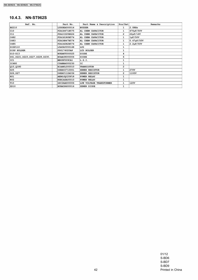
10.4.3. NN-ST962SRef. No. Part No. Part Name & Description Pcs/Set Remarks
BZ210 L0DDEA000014 BUZZER 1 2.0KHzC10 F2A1H471B575 AL CHEM CAPACITOR 1 470µF/50VC11 F2A1C220B624 AL CHEM CAPACITOR 2 22µF/16VC482 F2A1H1R0B574 AL CHEM CAPACITOR 1 1µF/50VC483 F2A1HR47B574 AL CHEM CAPACITOR 1 0.47µF/50VC485 F2A1H2R2B574 AL CHEM CAPACITOR 1 2.2µF/50VDISP110 L5AYAYY00168 LCD 1DISP HOLDER F66174U20AP LCD HOLDER 1D10-D13 B0EAKT000025 DIODE 4D41,D221,D223,D227,D228,D230. B0AACK000004 DIODE 6IC1 MN69F009CA1 L.S.I. 1IC480 C0ABBA000230 IC 1Q10,Q180 B1AAKL000010 TRANSISTOR 2D25 D4EAY2710001 ZENER RESISTOR 1 270VD26,D27 D4EAY112A036 ZENER RESISTOR 2 1100VRY1 AEBGJQC25F18 POWER RELAY 1RY2 K6B1AZA00010 POWER RELAY 1T10 G4C2AAD00006 LOW VOLTAGE TRANSFORMER 1 120VZD10 B0BA5R600016 ZENER DIODE 1
42
NN-SE992S / NN-SD982S / NN-ST962S
01/12S-BD6S-BD7S-BD9Printed in China