Microwave Interference Scanning Inspection of Nonmetallic ... · PDF fileMicrowave...
15
Microwave Interference Scanning Inspection of Nonmetallic Pipes Karl Schmidt 1, Taher Aljundi 2 , Ghazzay Al Subaii 2 and Jack Little 1 1 Evisive, Inc. 8867 Highland Road, #378 Baton Rouge, LA 70808 (225) 769-2751 [email protected] 2 Saudi Aramco Dhahran 31311, KSA +966-3-872-5783 [email protected] ABSTRACT Nonmetallic pipes are used in many petroleum extraction and processing applications. Both polyethylene and composite pipes present unique challenges for nondestructive examination (NDT). Microwave interferometry is a novel method for inspection of dielectric materials which addresses these challenges. Saudi Aramco has investigated microwave interferometry as one of the NDT techniques they are readying for field application for potential composite pipe transportation pipelines. Evisive has participated in this and other programs. Investigations with Saudi Aramco have also included application to resin overwrap repair on metal pipe. Evisive has also supported other research and service organizations in application of the microwave interferometry method to additional composite pipe applications, as well as polyethylene pipe. In this report, results are presented for microwave interference scanning with a variety of positioning systems to inspect Glassfiber Reinforced Epoxy (GRE) pipes for defects like wall thinning due to erosion, and weld inspection in high density polyethylene pipe welds. The microwave interferometry method was capable of detecting a localized gouge roughly 25% of the wall thickness in GRE material. Field demonstrations by of the system by Saudi Aramco also showed capabilities to detect voids in GRE pipe used for sea water applications. Additional field and laboratory demonstrations have shown that the microwave interferometry method is able to detect erosion in composite pipe, artificial and natural defects and bond quality in welds in HDPE pipes. INTRODUCTION The vast majority of the pipes used to transport hydrocarbons around the world are made of carbon steel pipes joined together using butt welds. These pipes are susceptible to corrosion and oil companies spend significant amounts of money on expensive corrosion inhibitor chemicals and inspections of these pipes to prevent leaks which interrupt production. Many major oil and gas companies including Saudi Aramco are moving towards the use of composite pipes for hydrocarbons transportation. The attractive characteristic of composite pipes is their immunity to corrosion. Unlike carbon steel pipes, composite pipes and fittings do not corrode. Saudi Aramco reports that this characteristic alone is worth more than $1.5 billion per year to in terms of corrosion inhabiting chemicals, replacement of corroded pipes and corrosion inspection costs. However, one of the limiting factors for the wide spread use of composite pipes in hydrocarbon applications is the inadequacy of traditional nondestructive inspection techniques to ensure the integrity of the pipes networks. High density Polyethylene pipes also offer resistance to corrosion, and present challenges to nondestructive testing. This report specifically addresses the application of microwave interference scanning to composite pipe by Saudi Aramco with Evisive; and reports briefly on relevant applications of microwave interferometry in other applications. Glassfiber Reinforced Epoxy (GRE) is a fiber glass filament embedded in a thermosetting resin (epoxy). GRE pipes and fittings targeted for this study are made by filament winding. This is a process of continuous winding of glass fibers (or tape), saturated with resin around a mandrel in a predetermined pattern under controlled tension. The inside diameter of the pipe or fitting is controlled by the diameter of the mandrel used while the wall thickness is determined by the number of windings. After the winding process is complete the pipe is cured in an autoclave at elevated temperature (each manufacturer has their own recipe for the temperature and duration of the curing
Transcript of Microwave Interference Scanning Inspection of Nonmetallic ... · PDF fileMicrowave...
Microwave Interference Scanning Inspection of Nonmetallic Pipes
Karl Schmidt1, Taher Aljundi2, Ghazzay Al Subaii2 and Jack Little1
1Evisive, Inc. 8867 Highland Road, #378 Baton Rouge, LA 70808
(225) 769-2751 [email protected]
2Saudi Aramco
Dhahran 31311, KSA +966-3-872-5783
[email protected] ABSTRACT Nonmetallic pipes are used in many petroleum extraction and processing applications. Both polyethylene and composite pipes present unique challenges for nondestructive examination (NDT). Microwave interferometry is a novel method for inspection of dielectric materials which addresses these challenges. Saudi Aramco has investigated microwave interferometry as one of the NDT techniques they are readying for field application for potential composite pipe transportation pipelines. Evisive has participated in this and other programs. Investigations with Saudi Aramco have also included application to resin overwrap repair on metal pipe. Evisive has also supported other research and service organizations in application of the microwave interferometry method to additional composite pipe applications, as well as polyethylene pipe. In this report, results are presented for microwave interference scanning with a variety of positioning systems to inspect Glassfiber Reinforced Epoxy (GRE) pipes for defects like wall thinning due to erosion, and weld inspection in high density polyethylene pipe welds. The microwave interferometry method was capable of detecting a localized gouge roughly 25% of the wall thickness in GRE material. Field demonstrations by of the system by Saudi Aramco also showed capabilities to detect voids in GRE pipe used for sea water applications. Additional field and laboratory demonstrations have shown that the microwave interferometry method is able to detect erosion in composite pipe, artificial and natural defects and bond quality in welds in HDPE pipes. INTRODUCTION The vast majority of the pipes used to transport hydrocarbons around the world are made of carbon steel pipes joined together using butt welds. These pipes are susceptible to corrosion and oil companies spend significant amounts of money on expensive corrosion inhibitor chemicals and inspections of these pipes to prevent leaks which interrupt production. Many major oil and gas companies including Saudi Aramco are moving towards the use of composite pipes for hydrocarbons transportation. The attractive characteristic of composite pipes is their immunity to corrosion. Unlike carbon steel pipes, composite pipes and fittings do not corrode. Saudi Aramco reports that this characteristic alone is worth more than $1.5 billion per year to in terms of corrosion inhabiting chemicals, replacement of corroded pipes and corrosion inspection costs. However, one of the limiting factors for the wide spread use of composite pipes in hydrocarbon applications is the inadequacy of traditional nondestructive inspection techniques to ensure the integrity of the pipes networks. High density Polyethylene pipes also offer resistance to corrosion, and present challenges to nondestructive testing. This report specifically addresses the application of microwave interference scanning to composite pipe by Saudi Aramco with Evisive; and reports briefly on relevant applications of microwave interferometry in other applications. Glassfiber Reinforced Epoxy (GRE) is a fiber glass filament embedded in a thermosetting resin (epoxy). GRE pipes and fittings targeted for this study are made by filament winding. This is a process of continuous winding of glass fibers (or tape), saturated with resin around a mandrel in a predetermined pattern under controlled tension. The inside diameter of the pipe or fitting is controlled by the diameter of the mandrel used while the wall thickness is determined by the number of windings. After the winding process is complete the pipe is cured in an autoclave at elevated temperature (each manufacturer has their own recipe for the temperature and duration of the curing
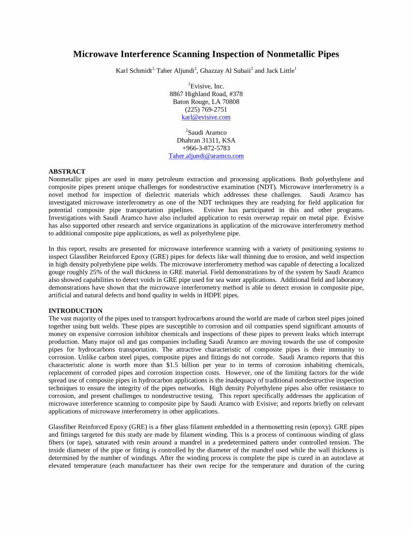
process). The winding process can be automated or it can be performed by hand. The later is more common for making the fittings which usually results in more manufacturing defects than an automated process. Composite pipes are currently used within Saudi Aramco facilities at a limited scale: mostly for non hydrocarbon applications; such as sea water treatment. Establishment of reliable NDT methods and defect acceptance criteria for quality assurance of composite pipes are important steps necessary for wide spread use in critical applications such as hydrocarbon systems.
Figure 1 a manual winding process for making a fitting and an automated winding process for making a pipe. (Courtesy of Bondstrand, KSA). Traditionally, composite pipes and fittings are inspected using visual inspection and hydrotesting. One nonmetallic pipes and fittings manufacturer reported that most of the in-service failures tracked over a period of 20 years of production were due to joints fabrication errors. This type of error cannot be detected using visual inspection or hydrotesting. In fact most of the in-service failures are due to defects that cannot be detected by visual and hydro testing as can be seen in Table 1 below for failure mechanisms compiled by a local manufacturer of composite pipes of a period of 20 years of production. Leak due to % of
leaks Description of cause Potential inspection
method
1 Adhesive bonded joint 34 Improper bonding/poor workmanship DR, IR at manufacturing 2 External impact 25 Body leak evidenced by impact marks Microwave NDT, DR 3 Overstress / over toque 15 Cracked flange AE 4 Body leak at fittings 14 Leaking body of fitting without evidence of
mishandling or external impact Hydrotesting
5 Key lock joint 5 Damaged o-ring and misalignment DR 6 Design / construction 5 Improper or insufficient supports during
hydrotesting and operation of the line Hydrotesting
7 Body leak at pipes 2 Leaking body of pipe without evidence of mishandling or impact damage
Hydrotesting
Table 1 Common Failure mechanisms experienced in-service over a period of 20 years. The Saudi Aramco study to evaluate microwave NDT to inspect composite pipes is part of an integrated program to investigate several NDT methods for possible use in a quality assurance program for composite pipes and fittings. Other techniques being investigated include low energy digital radiography, Low frequency UT, and pulsed themography. Saudi Aramco do not expect any one NDT technique to be sufficient to address all the inspection requirements for composites, instead few techniques might be needed to complement each other and satisfy the
inspection requirements. High frequency ultrasonic (≥ 1 MHz) has been successfully used for the inspection of composites in the aerospace applications. However, the composites in aerospace applications are cured under high autoclave pressures (as high as 85 psi), hence producing a high density composite. In the oil and gas applications, composite pipes and fittings are cured in autoclaves under atmospheric pressure to control cost. As a result, the composite pipes and fittings have a relatively high percentage of voids which attenuate ultrasonic waves to the extent where high frequency ultrasonic inspection is no longer a useful technique for the inspection of such material. TECHNOLOGY AND SYSTEM DESCRIPTION
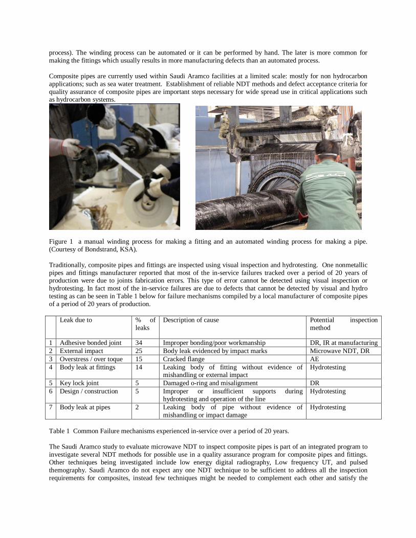
Microwaves are part of the electromagnetic spectrum with wave lengths in the centimeter range and frequencies from 0.3 to 300 GHz.
Figure 2 the electromagnetic spectrum (Courtesy of Wikipedia.com).
The basic operating principle of this technology is based on the backscattering of microwaves as they travel from one media to another media with different dielectric constant. So a defect in the nonmetallic pipe is viewed as a new media with a different dielectric constant from the surrounding material. Hence it scatters the microwaves at a different rate and phase from the surrounding medium. The microwave system used in this study has a probe configured with; a transmitter diode that generates the microwaves and projects them past two sensor diodes, which record baseline voltage strength (see Figure 3). The microwaves then penetrate the test piece and at each interface, a change in the dielectric constant in the material energy is reflected. So a delamination or a gouge in the material will have a different dielectric constant from the pipe material (GRE) and hence it will reflect and transmit the microwave energy according to the differences in dielectric constant. These reflected signals are combined with the transmitted signal and the interference pattern is converted to a voltage by the sensor diodes. The resulting signals are then amplified, digitized and converted into images. The images represent the reflected microwave energy from the entire volume of inspected material. The microwave energy transmits through gaps and material variations, and is reflected entirely by a conductive surface. This permits examination from one surface, without coupling media, through non contacting layers and coatings. The method does not work on or through metal surfaces or water. But, these conductors make effective “backing” material for inspections of liquid filled pipe or resin coated wrap on metal pipe.

The two receiver diodes are placed 1/4 a wavelength apart and each one generates an image of the received signal. The system as it scans over the surface of a pipe generates 3 images, one from diode A (called channel A) and one from diode B (called channel B) and a third image is numerically calculated as the difference between channels A and B (called channel C). The inspection system consists of a laptop computer, instrument case, umbilical cable, scanning device, and the microwave probe. The scans are performed from one side of inspected sample much like conventional ultrasonic testing with no couplant required.
Figure 4 Microwave system components.
SYSTEM PERFORMANCE The system was tested in the Saudi Aramco laboratory using composite pipes segments made by two different local manufacturers. One of the pipes had a “gouge” machined in it to simulate erosion. Other demonstrations were performed using metal coins taped on the inside of the pipe to compare the signal strengths between different probes at different frequencies. After the laboratory tests, the Saudi Aramco team took the system into the field to inspect
Figure3 Schematic of the microwave probe and principle operation.
the metal surface of a carbon steel pipes through a clock spring repair. And then to examine the composite wall of a pipe at the sea water injection plant at Qurrayah, KSA. Laboratory Tests: Laboratory testing using pipes segments continued throughout this project. Several pipe
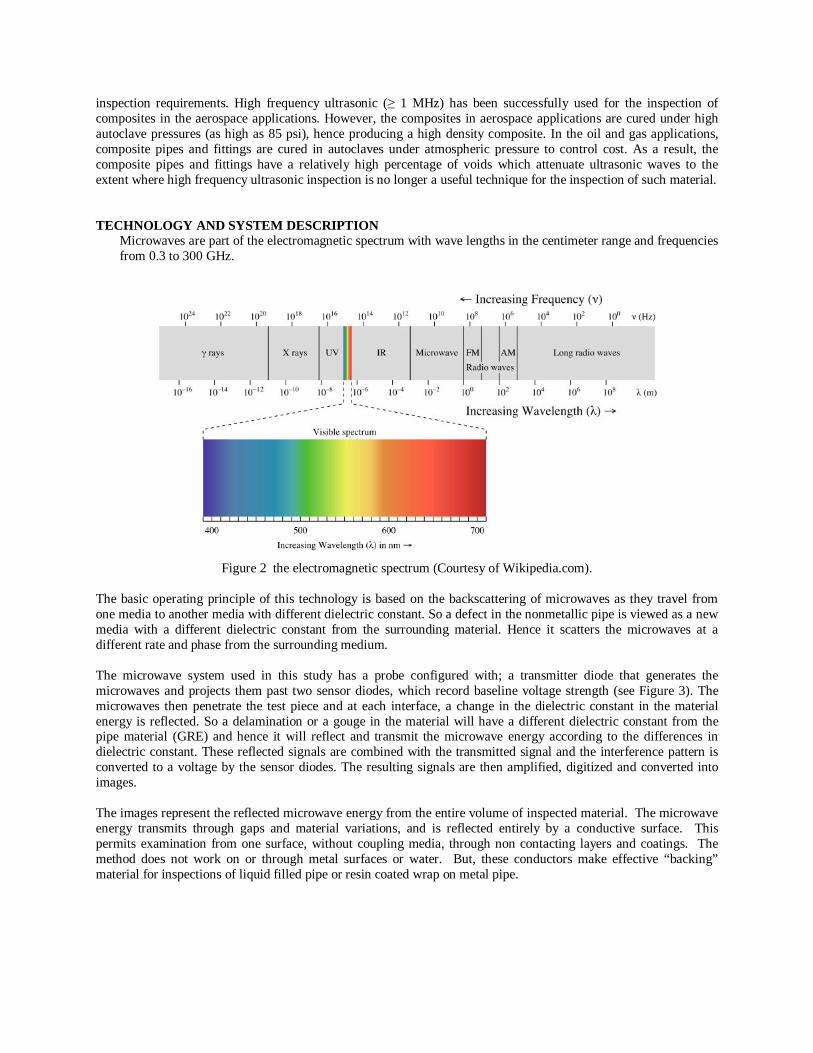
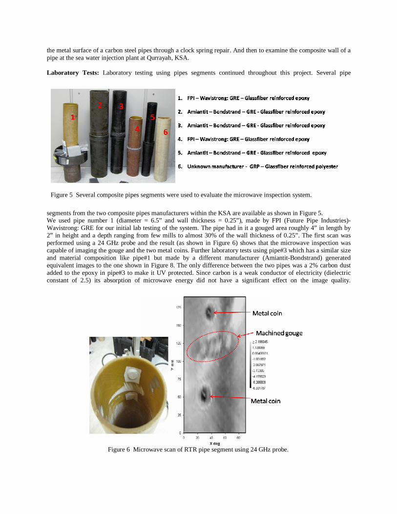
segments from the two composite pipes manufacturers within the KSA are available as shown in Figure 5. We used pipe number 1 (diameter = 6.5” and wall thickness = 0.25”), made by FPI (Future Pipe Industries)-Wavistrong: GRE for our initial lab testing of the system. The pipe had in it a gouged area roughly 4” in length by 2” in height and a depth ranging from few mills to almost 30% of the wall thickness of 0.25”. The first scan was performed using a 24 GHz probe and the result (as shown in Figure 6) shows that the microwave inspection was capable of imaging the gouge and the two metal coins. Further laboratory tests using pipe#3 which has a similar size and material composition like pipe#1 but made by a different manufacturer (Amiantit-Bondstrand) generated equivalent images to the one shown in Figure 8. The only difference between the two pipes was a 2% carbon dust added to the epoxy in pipe#3 to make it UV protected. Since carbon is a weak conductor of electricity (dielectric constant of 2.5) its absorption of microwave energy did not have a significant effect on the image quality.
Figure 6 Microwave scan of RTR pipe segment using 24 GHz probe.
Figure 5 Several composite pipes segments were used to evaluate the microwave inspection system.
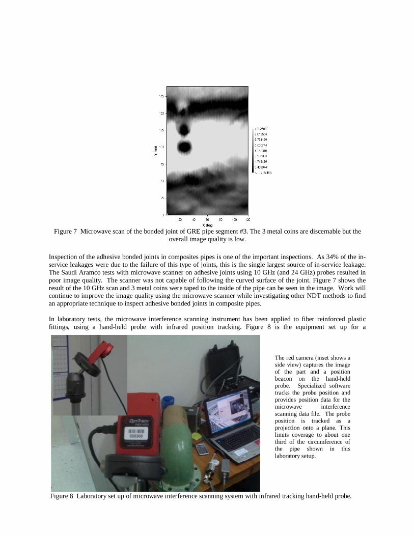
Inspection of the adhesive bonded joints in composites pipes is one of the important inspections. As 34% of the in-service leakages were due to the failure of this type of joints, this is the single largest source of in-service leakage. The Saudi Aramco tests with microwave scanner on adhesive joints using 10 GHz (and 24 GHz) probes resulted in poor image quality. The scanner was not capable of following the curved surface of the joint. Figure 7 shows the result of the 10 GHz scan and 3 metal coins were taped to the inside of the pipe can be seen in the image. Work will continue to improve the image quality using the microwave scanner while investigating other NDT methods to find an appropriate technique to inspect adhesive bonded joints in composite pipes. In laboratory tests, the microwave interference scanning instrument has been applied to fiber reinforced plastic fittings, using a hand-held probe with infrared position tracking. Figure 8 is the equipment set up for a
The red camera (inset shows a side view) captures the image of the part and a position beacon on the hand-held probe. Specialized software tracks the probe position and provides position data for the microwave interference scanning data file. The probe position is tracked as a projection onto a plane. This limits coverage to about one third of the circumference of the pipe shown in this laboratory setup.
Figure 7 Microwave scan of the bonded joint of GRE pipe segment #3. The 3 metal coins are discernable but the
overall image quality is low.
Figure 8 Laboratory set up of microwave interference scanning system with infrared tracking hand-held probe.

demonstration on a small FRP elbow. The microwave interferometry scan image of the laboratory set up on a sample elbow is shown in Figure 9. The images show a region of the part before and after inserting a 1 X ¾ by 3/8 inch deep gouge. The curved region of
the scan on the part is projected onto a plane by the infrared tracking software. The infrared tracking system has been successfully deployed in field applications for large tires (mining) and flexible couplings (nuclear power plants). Further development and testing is anticipated for piping system applications. Clock Spring Inspection: Inspection of the metal surface under a clock spring repair is another important application for microwave NDT. A clock spring repair is a composite reinforcement of carbon steel pipes to repair a leak or a corrosion pit by wrapping layers of composite material held together with epoxy. The surface of the metal is prepared using sand blasting and then the epoxy and composite wrap are applied and wrapped around the surface (usually 8 wraps) in a manual process. This repair is common in the oil and gas industry. If there is a void between the wrap and the metal surface due to poor workmanship then the corrosion process will resume. The microwave scanner was used to inspect the metal surface under such a repair and the results were successful.
Figure 10 Microwave inspection of a clock spring repair.
Figure 9 Before and after images and photograph of a gouge in an FRP elbow. Microwave interference scan was performed using the infrared tracking system and hand-held probe.
Two scans a portion of the elbow, performed by hand using infrared position tracking. Linear “trail” is from data collection with probe lifted off the part surface creating a local phase difference to the part surface. The gouge was inserted after the scan at left, and is apparent in the scan below.
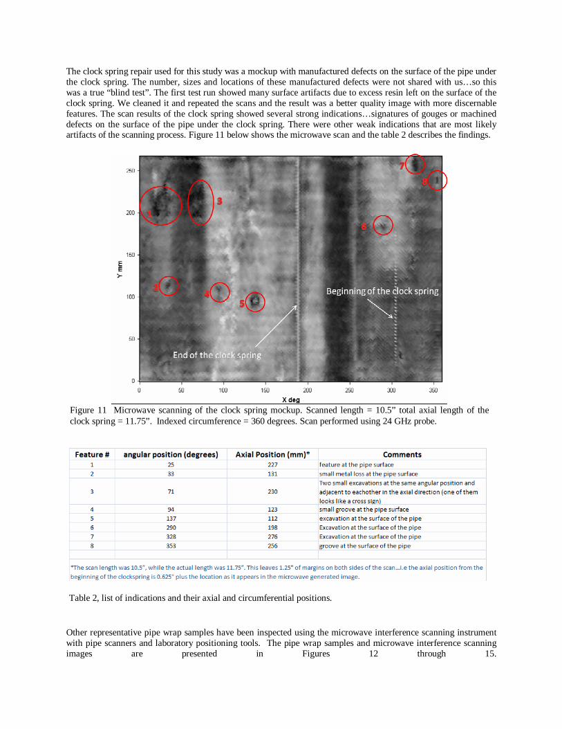
The clock spring repair used for this study was a mockup with manufactured defects on the surface of the pipe under the clock spring. The number, sizes and locations of these manufactured defects were not shared with us…so this was a true “blind test”. The first test run showed many surface artifacts due to excess resin left on the surface of the clock spring. We cleaned it and repeated the scans and the result was a better quality image with more discernable features. The scan results of the clock spring showed several strong indications…signatures of gouges or machined defects on the surface of the pipe under the clock spring. There were other weak indications that are most likely artifacts of the scanning process. Figure 11 below shows the microwave scan and the table 2 describes the findings.
Other representative pipe wrap samples have been inspected using the microwave interference scanning instrument with pipe scanners and laboratory positioning tools. The pipe wrap samples and microwave interference scanning images are presented in Figures 12 through 15.
Table 2, list of indications and their axial and circumferential positions.
Figure 11 Microwave scanning of the clock spring mockup. Scanned length = 10.5” total axial length of the clock spring = 11.75”. Indexed circumference = 360 degrees. Scan performed using 24 GHz probe.
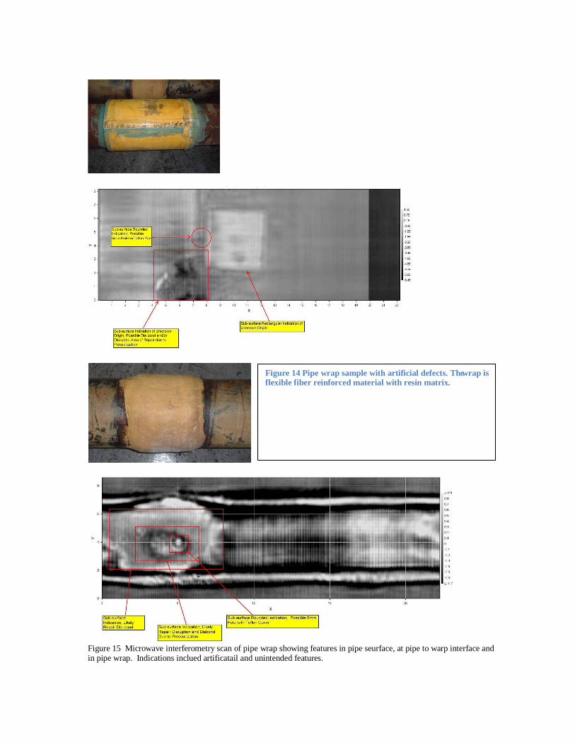
Figure 15 Microwave interferometry scan of pipe wrap showing features in pipe seurface, at pipe to warp interface and in pipe wrap. Indications inclued artificatail and unintended features.
Figure 14 Pipe wrap sample with artificial defects. The wrap is flexible fiber reinforced material with resin matrix.
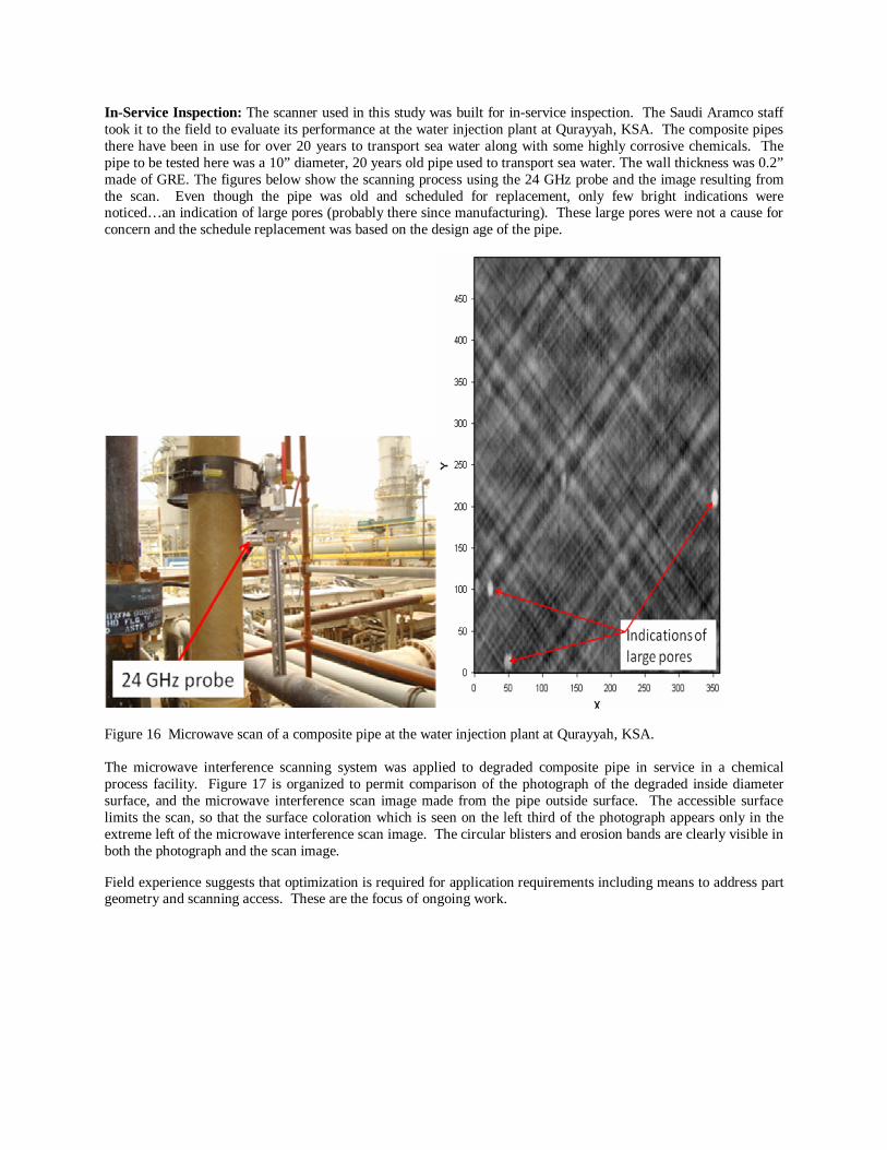
In-Service Inspection: The scanner used in this study was built for in-service inspection. The Saudi Aramco staff took it to the field to evaluate its performance at the water injection plant at Qurayyah, KSA. The composite pipes there have been in use for over 20 years to transport sea water along with some highly corrosive chemicals. The pipe to be tested here was a 10” diameter, 20 years old pipe used to transport sea water. The wall thickness was 0.2” made of GRE. The figures below show the scanning process using the 24 GHz probe and the image resulting from the scan. Even though the pipe was old and scheduled for replacement, only few bright indications were noticed…an indication of large pores (probably there since manufacturing). These large pores were not a cause for concern and the schedule replacement was based on the design age of the pipe.
Figure 16 Microwave scan of a composite pipe at the water injection plant at Qurayyah, KSA. The microwave interference scanning system was applied to degraded composite pipe in service in a chemical process facility. Figure 17 is organized to permit comparison of the photograph of the degraded inside diameter surface, and the microwave interference scan image made from the pipe outside surface. The accessible surface limits the scan, so that the surface coloration which is seen on the left third of the photograph appears only in the extreme left of the microwave interference scan image. The circular blisters and erosion bands are clearly visible in both the photograph and the scan image.
Field experience suggests that optimization is required for application requirements including means to address part geometry and scanning access. These are the focus of ongoing work.

Inspection of High Density Polyethylene Pipe: High density polyethylene (HDPE) is used in a wide range of petroleum and power industry applications. Typical applications include transportation pipelines for liquid and gas products, gathering pipelines; and service water and support system piping in process facilities. There are two major methods of forming pipe joints: thermal fusion of pipe ends and electro-fusion of couplings. Evisive licensee Exova, of Broxburn, UK, have applied the method to both thermal fusion and electro-fusion joints, and have completed a number of destructive examinations to validate the technique in each application. In this report will
Figure 18 An example of polyethylene pipe fusing equipment, courtesy McElroy, Manufacturing. The machine prepares pipe ends, heats the end surfaces, and presses the pipe sections together to form the welded joint.
Figure 17 Photograph (left) of inside surface and microwave interference scan image from outside surfaced. The circular blisters and erosion bands are clearly visible in both the photograph and the scan image.

address the thermal fusion applications.
In thermally fused joints, the pipe ends are heated by a blade element which is placed between the faces of the weld preparation. When the element is removed, the pipe ends are compressed together axially, and cool to form the welded joint. Essentially similar processes are scalable from the pipe diameters considerably smaller than that
Figure 19 Microtome of HDPE weld. Upper (outside surface) weld bead has been removed for inspection access. Inner bead has two lobes of protruded material which result from axial compression of the joint during formation.
Figure 20 Microwave interference scan image of end drilled holes in thermal fused HDPE pipe segment, and destructive sections of weld including drilled holes.
shown in Figure 18, to much larger. Large diameter pipe may have wall thickness above 3 inches. The axial compression of the weld joint leaves a bead on the inside and outside diameter of the pipe. A microtome of a thermally fused weld is shown in Figure 19. The outside bead has been removed for inspection. The variation in material properties through the weld is apparent in the change in opacity of the material. The microwave interferometry method has been applied to HDPE weld joints in laboratory and field programs.
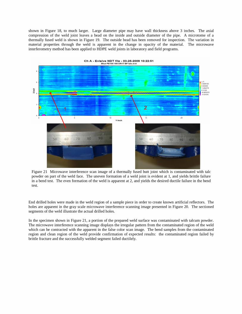
End drilled holes were made in the weld region of a sample piece in order to create known artificial reflectors. The holes are apparent in the gray scale microwave interference scanning image presented in Figure 20. The sectioned segments of the weld illustrate the actual drilled holes. In the specimen shown in Figure 21, a portion of the prepared weld surface was contaminated with talcum powder. The microwave interference scanning image displays the irregular pattern from the contaminated region of the weld which can be contracted with the apparent in the false color scan image. The bend samples from the contaminated region and clean region of the weld provide confirmation of expected results: the contaminated region failed by brittle fracture and the successfully welded segment failed ductilely.
Figure 21 Microwave interference scan image of a thermally fused butt joint which is contaminated with talc powder on part of the weld face. The uneven formation of a weld joint is evident at 1, and yields brittle failure in a bend test. The even formation of the weld is apparent at 2, and yields the desired ductile failure in the bend test.
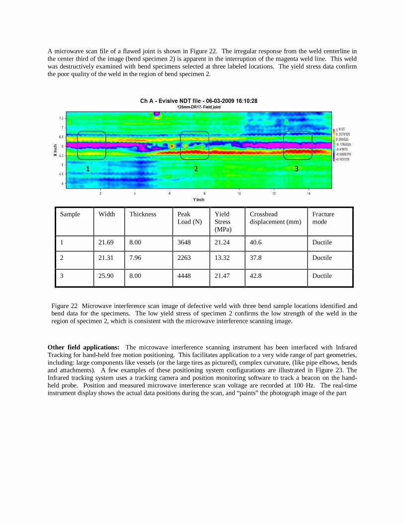
A microwave scan file of a flawed joint is shown in Figure 22. The irregular response from the weld centerline in the center third of the image (bend specimen 2) is apparent in the interruption of the magenta weld line. This weld was destructively examined with bend specimens selected at three labeled locations. The yield stress data confirm the poor quality of the weld in the region of bend specimen 2.
Other field applications: The microwave interference scanning instrument has been interfaced with Infrared Tracking for hand-held free motion positioning. This facilitates application to a very wide range of part geometries, including: large components like vessels (or the large tires as pictured), complex curvature, (like pipe elbows, bends and attachments). A few examples of these positioning system configurations are illustrated in Figure 23. The Infrared tracking system uses a tracking camera and position monitoring software to track a beacon on the hand- held probe. Position and measured microwave interference scan voltage are recorded at 100 Hz. The real-time instrument display shows the actual data positions during the scan, and “paints” the photograph image of the part
Sample Width Thickness Peak Load (N)
Yield Stress (MPa)
Crosshead displacement (mm)
Fracture mode
1 21.69 8.00 3648 21.24 40.6 Ductile
2 21.31 7.96 2263 13.32 37.8 Ductile
3 25.90 8.00 4448 21.47 42.8 Ductile
Figure 22 Microwave interference scan image of defective weld with three bend sample locations identified and bend data for the specimens. The low yield stress of specimen 2 confirms the low strength of the weld in the region of specimen 2, which is consistent with the microwave interference scanning image.
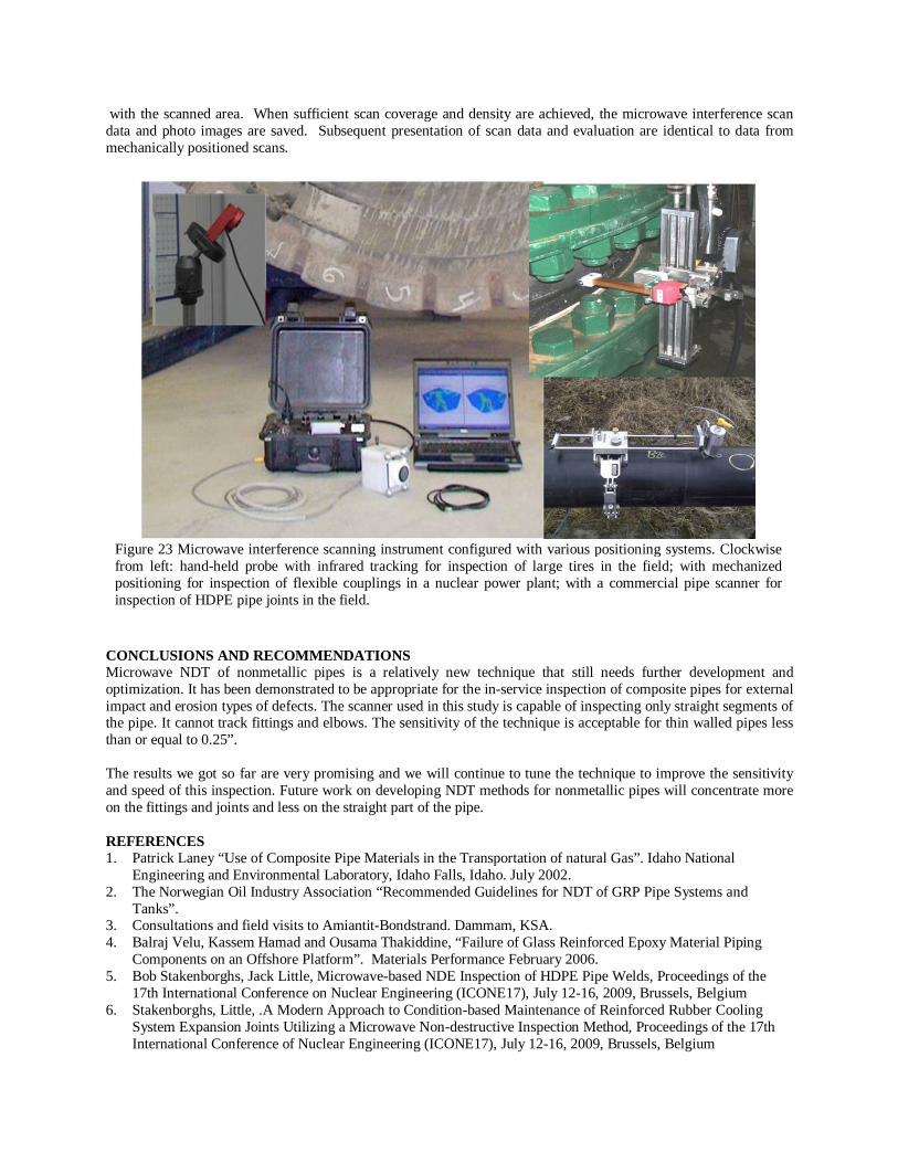
with the scanned area. When sufficient scan coverage and density are achieved, the microwave interference scan data and photo images are saved. Subsequent presentation of scan data and evaluation are identical to data from mechanically positioned scans.
CONCLUSIONS AND RECOMMENDATIONS Microwave NDT of nonmetallic pipes is a relatively new technique that still needs further development and optimization. It has been demonstrated to be appropriate for the in-service inspection of composite pipes for external impact and erosion types of defects. The scanner used in this study is capable of inspecting only straight segments of the pipe. It cannot track fittings and elbows. The sensitivity of the technique is acceptable for thin walled pipes less than or equal to 0.25”. The results we got so far are very promising and we will continue to tune the technique to improve the sensitivity and speed of this inspection. Future work on developing NDT methods for nonmetallic pipes will concentrate more on the fittings and joints and less on the straight part of the pipe. REFERENCES 1. Patrick Laney “Use of Composite Pipe Materials in the Transportation of natural Gas”. Idaho National
Engineering and Environmental Laboratory, Idaho Falls, Idaho. July 2002. 2. The Norwegian Oil Industry Association “Recommended Guidelines for NDT of GRP Pipe Systems and
Tanks”. 3. Consultations and field visits to Amiantit-Bondstrand. Dammam, KSA. 4. Balraj Velu, Kassem Hamad and Ousama Thakiddine, “Failure of Glass Reinforced Epoxy Material Piping
Components on an Offshore Platform”. Materials Performance February 2006. 5. Bob Stakenborghs, Jack Little, Microwave-based NDE Inspection of HDPE Pipe Welds, Proceedings of the
17th International Conference on Nuclear Engineering (ICONE17), July 12-16, 2009, Brussels, Belgium 6. Stakenborghs, Little, .A Modern Approach to Condition-based Maintenance of Reinforced Rubber Cooling
System Expansion Joints Utilizing a Microwave Non-destructive Inspection Method, Proceedings of the 17th International Conference of Nuclear Engineering (ICONE17), July 12-16, 2009, Brussels, Belgium
Figure 23 Microwave interference scanning instrument configured with various positioning systems. Clockwise from left: hand-held probe with infrared tracking for inspection of large tires in the field; with mechanized positioning for inspection of flexible couplings in a nuclear power plant; with a commercial pipe scanner for inspection of HDPE pipe joints in the field.