Microwave data link AL24F MP155 - radioport.ru file3.3 cross polarization of radio link ... 3.7...
63
Microwave data link AL24F MP155 Installation and operation manual Dokument Vision: 1.6 Published: 4.1.2010 Last Modification: 20.07.2010 www.alcoma.eu
Transcript of Microwave data link AL24F MP155 - radioport.ru file3.3 cross polarization of radio link ... 3.7...

Microwave data link
AL24F MP155
Installation and operation manual
Dokument Vision: 1.6 Published: 4.1.2010 Last Modification: 20.07.2010 www.alcoma.eu

CONTENTS page 1. INTRODUCTION .................................................................................................................................................. 2
1.1 BASIC DATA.................................................................................................................................................... 3 2. DESCRIPTION OF THE LINK.................................................................................................................................. 5
2.1 THE PROTECTED TERMINAL BOX ALSX .................................................................................................................. 7 2.2 THE ODU OUTDOOR UNIT .............................................................................................................................. 12
3. INSTALLATION INSTRUCTIONS.......................................................................................................................... 16 3.1 EVALUATION OF SUITABLE PLACEMENT ............................................................................................................... 16 3.2 PLACEMENT OF THE ANTENNA ON A SUPPORT CONSTRUCTION................................................................................... 16 3.3 CROSS POLARIZATION OF RADIO LINK ............................................................................................................... 18 3.4 LOCAL FREQUENCY COORDINATION .................................................................................................................... 19 3.5 STATION INSTALLATION ................................................................................................................................... 20 3.6 INSTALLATION OF THE ANTENNA SYSTEM ............................................................................................................. 21 3.7 INSTALLATION OF THE ANTENNA RADIATOR ELEMENT ON ODU ................................................................................. 21 3.8 RADIO LINK INSTALLATION ................................................................................................................................ 22 3.9 GROUNDING ................................................................................................................................................ 25 3.10 MANIPULATION WITH THE USER SPACE COVER ..................................................................................................... 26 3.11 INSTALLATION OF INTERCONNECT CABLE.............................................................................................................. 27 3.12 EXPANSION OF ALS3...................................................................................................................................... 29 3.13 BEFORE PUTTING THE RADIO LINK INTO OPERATION ............................................................................................... 30 3.14 ACCESSORIES ................................................................................................................................................ 31
4. SETTING OF THE RADIO LINK AND ITS COMMISSIONING .................................................................................. 33 4.1 ANTENNA POINTING ....................................................................................................................................... 33 4.2 CHANGE OF POLARIZATION .............................................................................................................................. 39 4.3 CONTROL CALCULATION ................................................................................................................................. 42 4.4 DIRECT CONNECTION OF A MONITORING PC........................................................................................................ 43
5. OPERATION INSTRUCTIONS.............................................................................................................................. 45 5.1 OPERATION.................................................................................................................................................. 45 5.2 SPECTRAL ANALYZER ...................................................................................................................................... 46 5.3 EMERGENCY CONDITIONS ................................................................................................................................ 47 5.4 REPAIRS ...................................................................................................................................................... 47 5.5 ENDING OF OPERATION – ECOLOGICAL LIQUIDATION ............................................................................................. 47
6. SAFETY CHECK .................................................................................................................................................. 48 7. RADIO RELAY LINK PARAMETERS...................................................................................................................... 49
7.1 FREQUENCY PLAN ..................................................................................................................................... 49 7.2 MODULATION, THRESHOLD SENSITIVITY AND TRANSFER CAPACITY OF THE CONNECTION ................................................. 50 7.3 TECHNICAL PARAMETERS................................................................................................................................. 51 7.4 ENVIRONMENT ............................................................................................................................................. 52 7.5 ANTENNA SYSTEMS ........................................................................................................................................ 53 7.6 REFERENCE RANGE OF THE AL24F MP155 RADIO LINK........................................................................................... 54
8. MAIN EQUIPMENT DIMENSIONS ...................................................................................................................... 55 8.1 ODU – OUTDOOR UNIT.............................................................................................................................. 55 8.2 PROTECTED TERMINAL BOX .............................................................................................................................. 55 8.3 ANTENNAS WITH ODU................................................................................................................................... 56
9. APPENDIX ......................................................................................................................................................... 61

AL24F MP155 Microwave Data Link
2/61 1.6
1. INTRODUCTION The radio relay link AL24F MP155 as a whole or as parts is not intended to be used by untrained personnel.
Installation, adjustments and maintenance must be performed only by a person with electrotechnical qualifications trained by the manufacturer.
The link AL24F MP155 is an information technology device, to which the ČSN EN 50 116 – Routine electrical safety testing in production standard applies. If the power supply (BKE-JS 38 – 480/UK, BKE-JS 150 – 480/DIN) is a part of delivered merchandise, a copy of its testing protocol can be ordered from the manufacturer.
Please read this operation manual carefully before installation and operation of the duplex microwave link for data transmission ALCOMA AL24F MP155. Please pay increased attention to the safety instructions that are marked like this in the text:
WARNING
Violating of thus marked safety instructions can cause serious injury to personnel.
CAUTION
Violating of thus marked instructions can cause damage to the equipment.

AL24F MP155 Microwave Data Link
3/61 1.6
1.1 BASIC DATA
License free frequency band 24 GHz
The ALCOMA AL24F MP155 link is designed as unattended
The data transmission capacity is up to 165 Mbit/s
Channel bandwidths can be adjusted either to 7 MHz, 14 MHz or 28 MHz
Digital modulations QPSK, 16 QAM, 32 QAM, 64 QAM, and 128 QAM
ATPC automatic output regulation (ATPC lowers mutual interference of links and lowers operational costs)
Advanced FEC forward error correction
ACM Adaptive Coding and Modulation
Full duplex operation
Point to Point type link
Cross polarization (vertical and horizontal polarizations at the same time)
Interfaces: 2 Ethernet 100Base-TX channels marked as User line 2 and User line 3
The spectral analyzer shows the spectra of received signal of the local and remote stations along the whole spectrum
The link consists of the outdoor ODU unit, protected terminal box ALS3, or ALS1 and the appropriate cables
The link is supervised by the ASD Client program through a web interface, hyperterminal, or SNMP protocol Ver. 1
For the monitoring program ASD Client actual version see the following web page: www.alcoma.eu
It is possible to insert several relay stations in a signal path if needed due to the path character
The radio relay link AL24F MP155 enables using of the antenna types ALCOMA ME, MP, and MPS
ODU contains the acoustic signalization of incoming signal level RSSI
WARNING
The microwave link outdoor unit contains a microwave transmitter, which causes the health risk of non-ionizing radiation while in operation. It is dangerous to look directly into the antenna, or stay close in front of it, while the transmitter is in operation. The danger increases in direct proportion to the transmitted output. It is not allowed to switch on the transmitter without connected parabolic antenna. During work on and presence by the antenna, while the transmitter is in operation, the Government Directive 480/2000 About protection of health against non-ionizing radiation requirements must be met.
AL24F MP155 Microwave Data Link
4/61 1.6
The radio relay link AL24F MP155 station consists of three main parts:
1. The outdoor microwave unit that is integral with the antenna contains:
o The RF block that includes the microwave receiver, power amplifier, and oscillators controlled by the phase-lock loop.
o The data block that includes 2 Ethernet 100/10 switches, a modem and the monitoring system supervised by a controller. The power supply block that consists of DC-DC transformers that power the whole station. This complete block has been designed on one printed circuit board (PCB) which removed a lot of circuits and thus significantly increased reliability.
(Then there is the outdoor microwave unit called ODU - Outdoor unit for short in the text.)
2. The antenna set with the parabolic antenna, the feed element and the pole attachment.
3. Considering placement of the data block in ODU, the station AL24F MP155 has an indoor unit reduced to the protected terminal box ALS3, or ALS1 that ensures transmission of customer data, powering of the station, and protection against the atmospheric origin overvoltage and overcurrent. (The protected terminal box is marked as ALSx in the further text.)
With regard to the transmitter frequency the outdoor unit is made in two versions:
• /A for the lower part of frequency range, i.e. 24 000 ÷ 24 060 MHz
• /B for the higher part of frequency range, i.e. 24 190 ÷ 24 250 MHz
ODU can be connected to the microwave parabolic antennas of the types ALCOMA AL1-24/ME, AL1-24/MPS (∅ 0.35 m), AL2-24/ME, AL2-24/MPS (∅ 0.65 m), AL3-24/MP, AL3-24/MPS (∅ 0.90 m), and AL4-24/MP, AL4-24/MPS (∅ 1.20 m). These antennas are standard equipped by icing protection (OPN) for use in demanding climatic conditions. The simply removable ODU is integrated with the antenna system into one compact whole.
Interconnection between the protected terminal box and ODU is done by a double shielded outside cable (S-STP Cat 7) with 4 pairs of conductors with the 100 Ω impedance. The link cable transmits customer data, powering for ODU and ODU monitoring signals.

AL24F MP155 Microwave Data Link
5/61 1.6
2. DESCRIPTION OF THE LINK User data are connected to the protected terminal box ALSx by the standard RJ45 connectors. The two-stage
terminal protection limits breakdowns caused by overvoltage originating in atmospheric electricity, or due to industrial breakdowns. The protected terminal box contains user selectable jumpers enabling its optimum grounding and adjustment.
Also ODU is powered using the protected terminal box. The power supply in the range of +36 to +72 V, with the typical value of +48 V, is protected by the tube thermal fuse T2.0 A. The presence of supply voltage is indicated by a green LED. The supply voltage is transported to ODU by all four pairs of connecting cable conductors.
CAUTION
It is important to keep proper link of all connecting cable conductors both in ODU and ALSx. There is danger of equipment damage in case that the links are not connected properly.
The main line power supply of the category SELV according to the ČSN EN 60950 "Information technology - Safety of information technology equipment …".
The power cable ALSx is connected by the connector that is screwed on the box of the protected terminal box, and so guarantees a reliable link.
The protected terminal box is connected to ODU by a single shielded cable with 4 pairs of conductors. This cable is both on the side of the protected terminal box, and the ODU side connected by the "Krone" cutting boxs. The link cable passes through cable screw-in grommets on both sides, and so it is firmly attached to the box. The total length of the link cable and the cable that brings data into the protected terminal box can be max. 200 m long for the 10 Mb/s Ethernet, for the Ethernet speed of 100 Mb/s it can be max. 100 m long. These lengths are set and verified for the recommended cable S-STP Cat. 7. by ACOME. The terminal box ALSx is passive and the cable length must be considered from the terminal user device all the way to ODU.
The mechanical design of the protected terminal box assumes installation into a 19" rack. The design allows sufficiently flexible arrangement of outputs without additional mechanical adjustments. The protected terminal box allows to bring the connection cable with ODU to the front, or back panel. Customer data and the power supply can be brought to the front panel only. The arrangement can be modified according to customer wishes, and it is possible to deliver an arrangement that will suit the station, while it not necessary to have the outputs identically arranged in a box.
The protected terminal box ALS1 can be installed into the 19" rack, or it is possible to supply it by a profile for installation to the DIN box TS35.
Expansion of the protected terminal box to more connections can be done at customer premises according to the description in the chapter 3.2. The customer premises expansion kit is delivered with all necessary components (printed circuit, mechanical parts and cables).
The ODU input has similar overvoltage protection as the one in the protected terminal box, including a separate supply voltage. The supply voltage separated in the overvoltage protection is brought to the switch-on power supply. Activity of the ODU supply is indicated by the green LED placed on the mother board in the space of the user terminal box. Monitoring data are added to the user line (Line3 + mgmt) in the outdoor unit (ODU).
The high frequency block of the AL24F MP155 link consists of a microwave receiver, transmitter, microwave oscillators and other support circuits.
Microwave oscillators generate signals for mixers in the receiver and transmitter. Its frequency is controlled by the PLL loop. Accuracy and stability of the frequency adjustment is determined by a crystal oscillator.
The intermediate frequency signal at the 350 MHz frequency from the modem is mixed with the signal from a microwave oscillator, filtered, and power amplified. The signal goes through a branch, where the transmitted output detection circuit resides. From there the transmitter signal goes through a diplexer to the transmitting antenna.

AL24F MP155 Microwave Data Link
6/61 1.6
A received signal from the parabolic antenna is led through the diplexer to the receiver. There it is amplified and mixed to the intermediate frequency of 140 MHz and further amplified. From there the signal goes to a modem.
Figure 1 The block schematic of the AL24F MP155 connection
The demodulated signal goes from the modem to a muldex, where user data (Ethernet) are separated from the monitoring data. The user data are sent to the protected terminal box again through the overvoltage protection by a connection cable with 4 pairs of conductors.
MW Power suply
Motherboard
Line 3 + Mgmt
Power = 48 V (+36 ÷ + 72 V)
ALSx
DC
– D
C ch
ange
r
=48
V
IF cable
Surge protection
Muldex 10/100 Eth
switch 10/100 Eth
switch
Modem QAM
µP
MW receiver
MW transmitter PLL PLL
Report
+12 V
+5 V
+3,3 V
+2,5 V
-5 V
-12 V
U det
Interface RS232C
RSSI
Line 3 + Mgmt Line 2
Surge protection
AL24F MP155 Microwave Data Link
7/61 1.6
The voltage on the RSSI connector (figure 5) is proportionate to the intensity of the signal received from the opposite station. This voltage determines the height of the tone for the acoustic transformer that serves as an indicator during pointing of the link.
Output Regulation
2.1 THE PROTECTED TERMINAL BOX ALSx
The protected terminal box (ALSx) is designated for a concurrent transmission of two Ethernet channels. The protected terminal box ALSx provides protection of the customer data transmission and the power supply of the station against overvoltage of atmospheric origin. It splits the ODU supply current to all four pairs of conductors of the cable connecting it with ODU.
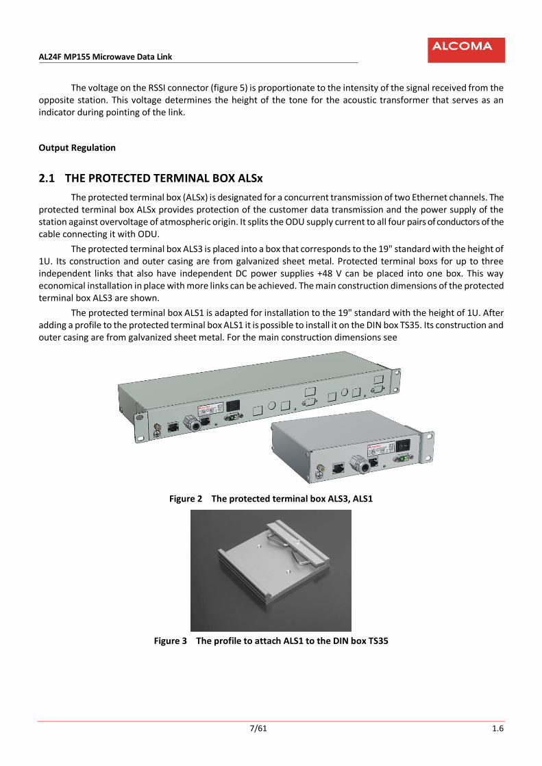
The protected terminal box ALS3 is placed into a box that corresponds to the 19" standard with the height of 1U. Its construction and outer casing are from galvanized sheet metal. Protected terminal boxs for up to three independent links that also have independent DC power supplies +48 V can be placed into one box. This way economical installation in place with more links can be achieved. The main construction dimensions of the protected terminal box ALS3 are shown.
The protected terminal box ALS1 is adapted for installation to the 19" standard with the height of 1U. After adding a profile to the protected terminal box ALS1 it is possible to install it on the DIN box TS35. Its construction and outer casing are from galvanized sheet metal. For the main construction dimensions see
Figure 2 The protected terminal box ALS3, ALS1
Figure 3 The profile to attach ALS1 to the DIN box TS35

AL24F MP155 Microwave Data Link
8/61 1.6
2.1.1 Input Connectors
Power supply connector on the front panel
+ –
The connection cable for this connector ends with the DSUB socket formed by the body type
3002W2CSXX99A10X that has power contacts of the 132C10019X type. Type designations correspond to the CONEC catalogue.
RJ45 connectors for user line input
User lines 2 and 3: 100Base-TX
Wiring Pins Description
1 +RX / +TX
2 –RX / –TX
3 +TX / +RX
4
5
Impedance ending 100 Ω
6 –TX / –RX
7 8
Impedance ending 100 Ω
Table 1 The RJ45 connector wiring - user lines Eth2 and Eth3
The AutoMDIX function assures switching of RX and TX as needed.

AL24F MP155 Microwave Data Link
9/61 1.6
2.1.2 Output Connectors
Cutting box "Krone" for the line 2
Attention!
The wiring is not the same as for the line 3
The marking of cable conductors Wiring Pins Description
S-STP Cat7 100Ω 4*ISTP
1 N/ANot connected
- - - - - -
2 Not connected
- - - - - -
3 +TX / +RX orange 1a
4 –TX / –RX white 1b
5 Shielding TX - - - Shielding S1
6 +RX / +TX green 2a
7 –RX / –TX white 2b
8 Shielding RX - - - Shielding S2
Table 2 The protected terminal box - cutting box “KRONE“ for the line 2
Cutting box "Krone" for the line 3
Attention!
The wiring is not the same as for the line 2
The marking of cable conductors Wiring Pins Description
S-STP Cat7 100Ω 4*ISTP
1 +TX / +RX brown 3a
2 –TX / –RX white 3b
3 Shielding TX - - - Shielding S3
4 +RX / +TX blue 4a
5 –RX / –TX white 4b
6 Shielding RX - - - Shielding S4
7 Not connected
- - - - - -
8 Not connected
- - - - - -
Table 3 The protected terminal box - cutting box “KRONE“ for the line 3

AL24F MP155 Microwave Data Link
10/61 1.6
The cable ACOME S-STP Cat7 has its shielding connected to ground through the metal input grommet. If the cable has the shielding coming out through one conductor it can be connected to any shielding pin.
The ARK500/2 connector for connection of power supply to PCB
Wiring Description
- Supply
+ Supply = 48 V
2.1.3 Indication
Board: Protected terminal box LED Abbreviation Meaning
POWER Power ON – indication of the station power supply being switched on

AL24F MP155 Microwave Data Link
11/61 1.6
2.1.4 Jumpers – without function for the S-STP Cat7 cable
Figure 4 The placement of jumpers on PCB of the ALSx protected terminal box
Jumper Position Description
JP1 A Shielding of the RX conductor pair for Line 2 is grounded
B Shielding of the RX conductor pair for Line 2 is not grounded
JP2 A Shielding of the TX conductor pair for Line 2 is grounded
B Shielding of the TX conductor pair for Line 2 is not grounded
JP3 A Shielding of the TX conductor pair for Line 3 is grounded
B Shielding of the TX conductor pair for Line 3 is not grounded
JP4 A Shielding of the RX conductor pair for Line 3 is grounded
B Shielding of the RX conductor pair for Line 3 is not grounded
Table 4 The meaning of jumpers of the protected terminal box ALSx
JP1 JP2 JP1 JP4 JP3

AL24F MP155 Microwave Data Link
12/61 1.6
2.2 THE ODU OUTDOOR UNIT
Figure 5 The ODU connection places
The standard station has a right side design, where the ODU and the antenna (while looking into the antenna) are on the right hand side of the support pipe. Left hand versions can be supplied if requested by a customer. Attachment of ODU depends on the used parabolic antenna.represent the right hand side installation of individual types of compact antennas and their main construction dimensions (the figure scales are not identical).
The outdoor unit (ODU) is placed into a full metal box. ODU is painted light gray that protects it from extreme temperatures, but especially contributes in creating of needed temperature balance inside of the ODU.
User terminal compartment
ConnectorN Connection IF cable
Bolt M8 Groundng ODU
Connector BNC RSSI voltage
ODU type A/B
Serial number

AL24F MP155 Microwave Data Link
13/61 1.6
Input Connectors Cutting box "Krone" for the line 2
The marking of cable conductors Wiring Pins Description
S-STP Cat7 100Ω 4*ISTP
1 Not connected
- - - - - -
2 Not connected
- - - - - -
3 +TX / +RX orange 1a
4 –TX / –RX white 1b
5 Shielding TX - - - Shielding S1
6 +RX / +TX green 2a
7 –RX / –TX white 2b
8 Shielding RX - - - Shielding S2
For simpler description the table does not consider the active functions AUTO MDIX.
Table 5 The outdoor unit - cutting box “KRONE“ for the line 2
Cutting box "Krone" for the line 3
The marking of cable conductors Wiring Pins Description
S-STP Cat7 100Ω 4*ISTP
1 +TX / +RX brown 3a
2 –TX / –RX white 3b
3 Shielding - - - Shielding S3
4 +RX / +TX blue 4a
5 –RX / –TX white 4b
6 Shielding - - - Shielding S4
7 Not connected
- - - - - -
8 Not connected
- - - - - -
Shielding S1 ÷ S4 for the cable ACOME S-STP Cat 7 is connected to ground through the metal input grommet.
Table 6 The outdoor unit - cutting box “KRONE“ for the line 3

AL24F MP155 Microwave Data Link
14/61 1.6
Figure 6 The ODU user space
Indication
LED Description Meaning
R RX LEVEL LOW Low level of the input microwave signal
R HIGH BER Increased errors on the microwave path
R FRAME LOSS Loss of frame sync
G OK Blinks = monitoring system does not register any error states at the moment. Light on / Light off = monitoring system indicates an error state
G +3.3 V Indication for stable output voltage of +3.3 V
Table 7 Meaning of LEDs in the ODU user space
User space cover
Cut connectors
Rotary selector switch
PC connector
Indications LED
ConnectorN Connection IF cable
Grounding ODU

AL24F MP155 Microwave Data Link
15/61 1.6
Rotary function switch
The rotary switch is located on the mother board. It is accessible after flipping off the lid on the ODU cover. The station does not have any other elements that can be changed during normal operation.
Position Description
0 Normal station operation
1 Pointing
2 ÷ F Reserve – not used yet
Table 8 Description of functions of the rotary switch in the ODU user space
The rotary switch in the position Pointing (1) also switches off a transmitter of the local station. Switching off of the output also in the remote station by the rotary switch can be used to find a level of interference signals (background noise) on given channels.
The AL24F MP155 station is optimally tuned during manufacture, set and tested in accordance with guaranteed parameters and customer requirements. If there is a new requirement to retune to a different channel or for a configuration change (possible on this equipment) after installation or inspection, it is possible to do this work using the monitoring program only. Retuning to a different frequency range that requires replacement of microwave filters can be done at the manufacturer only.

AL24F MP155 Microwave Data Link
16/61 1.6
3. INSTALLATION INSTRUCTIONS
3.1 EVALUATION OF SUITABLE PLACEMENT
For installation and proper operation of the radio link the following must be provided:
Direct optical visibility Place for attachment of antenna with ODU A place for the protected terminal box ALSx Path to lay the ODU – ALSx connection cable
Guaranteed direct visibility is not always sufficient guarantee of a quality connection. A condition for a trouble free propagation of electromagnetic waves is a pure radio visibility. If fixed objects, like tree tops, mountains or buildings are too close to the signal route, they can distort or attenuate a radio signal. This occurs even in cases when these obstructions do not prevent direct visibility. This phenomenon can be explained by the radio beam Fresnel zone – an elliptical area that immediately surrounds the direct visibility axis (the line between link antennas). Size of this zone varies depending on the hop length and radio signal frequency. The Fresnel zone must be calculated before design of the wireless link and it must be verified that it will not be disturbed by any obstacles.
Figure 7 The Fresnel zone
Figure 7 shows situation when a solid object penetrates a Fresnel zone of signal propagation. The obstacle, just like the one on the figure, causes bending of the beam along the sharp edge. This beam then arrives at the receiver antenna little bit later than the direct beam. In other words there are two identical signals coming to the antenna, but with various phases, which strongly degrades the signal quality; and this can cause temporary break in data transmission. Trees or other “soft” objects infringing on the Fresnel zone attenuate the radio signal. In short: The fact that you can see the opposite side does not mean that you can set up a quality radio connection.
3.2 PLACEMENT OF THE ANTENNA ON A SUPPORT CONSTRUCTION
The antenna of radio link must be placed sufficiently far away from other antennas, in order to avoid undesirable perturbation of radio signal. Badly installed antenna will cause deterioration of our transmitted signal and also of the signals of neighboring links. During installation of a radio relay link we need to calculate with a distance from the roof edge or different obstacles that can be present on the roof (A/C, elevator shaft…). The following figures show incorrect and correct ways of installation of radio relay link antenna on the supporting construction.
Line of sight
Fresnel zone

AL24F MP155 Microwave Data Link
17/61 1.6
Figure 8 Improper placement of antenna on mounting pipe
Figure 9 Proper placement of antenna on mounting pipe
1,4
m
0,3
m
Roof line Roof line
1,3 m More than 0,3 m
Roof line Roof line
0,3
m
0,6
m
0,3 m
Roof line Roof line
More than 12,5 m
2,5
m
1,4
m
1,3 m

AL24F MP155 Microwave Data Link
18/61 1.6
Obstacle distance
[m] 0 0.3 0.6 0.9 1.2 1.5 1.8 2.1 2.4 2.8 3.1 6.1 9.2 12 >12.5
Height of antenna
above ob-stacle [m]
0.3 0.6 0.9 1.2 1.3 1.4 1.4 1.4 1.4 1.5 1.5 1.8 2.1 2.3 2.5
Table 9 Recommended antenna placements considering a distance from an obstacle1
3.3 CROSS POLARIZATION OF RADIO LINK
The AL24F MP155 radio link for unlicensed 24 GHz band uses horizontal and vertical polarization. The microwave coupler of transmitted and received signal in ODU consists of the polarization switch and band filters. figure 10 is shown for easier understanding of the polarization beam splitter of transmitted and received signals.
Figure 10 The cross polarization of the radio link AL24F MP155
1 Table values correspond to an average antenna size and normal climatic conditions. Parameters of the used radio link type and climatic conditions have to be always taken into account.
Received signal polarization
ODU B horizontal polarization
Transmittedsignal polarization
ODU AVertical polarization
Transmitted signalpolarization
Received signal polarization

AL24F MP155 Microwave Data Link
19/61 1.6
3.4 LOCAL FREQUENCY COORDINATION
If there is more 24 GHz frequency band radio links in one location, polarization, or possibly link channel numbers must be selected to eliminate undesirable interference. The following figure 11 shows possible polarization combinations. Separation by channels is also possible – however, this possibility means using narrower transmitting band (lower transmission rate).
Figure 11 The examples of channel and polarization usage in case of more connections in one location
ODU A vertical transmitted polarization
ODU B horizontal transmitted polarization
>1 m
ODU A horizontal transmitted polarization
ODU B verticaltransmitted polarization
A)
B) ODU A vertical transmitted polarization
ODU B horizontal transmitted polarization
>1 m
ODU A horizontal transmitted polarization
ODU B vertical transmitted polarization

AL24F MP155 Microwave Data Link
20/61 1.6
3.5 STATION INSTALLATION
Figure 12 Attaching of the feed element to the ODU MP3
Figure 13 Attaching of the antenna radiator element to the AL3-24/MP, AL4-24/MP antennas
WARNING
The radio relay link AL24F MP155 is not intended to be used by non-specialist personnel. The equipment must be operated at least by personnel familiar with it (Paragraph 3, of the Public Notice No. 50/1978). Installation, adjusting and maintenance must be performed by the manufacturer instructed personnel with electrotechnical qualifications (Paragraph 5, Public Notice No. 50/1978). Therefore the following chapters do not contain work procedures split into individual steps.
Bolts M6 x 40
Waveguide transformer
Silicone „O“ ring
Bolts M4
Radiator
Mirror
Valve for pressure equalization Grounding ODU
ODU box
AL24F MP155 Microwave Data Link
21/61 1.6
3.6 INSTALLATION OF THE ANTENNA SYSTEM
Station antenna systems are attached to a vertical steel pipe that is a part of a girder mast structure, or to other steel constructions firmly connected to the building, on which the station is being installed. Diameters of supporting pipes are set by the table 16 on the page 53.
The antenna unit may not be installed on building equipment that have not been set or modified for this purpose.
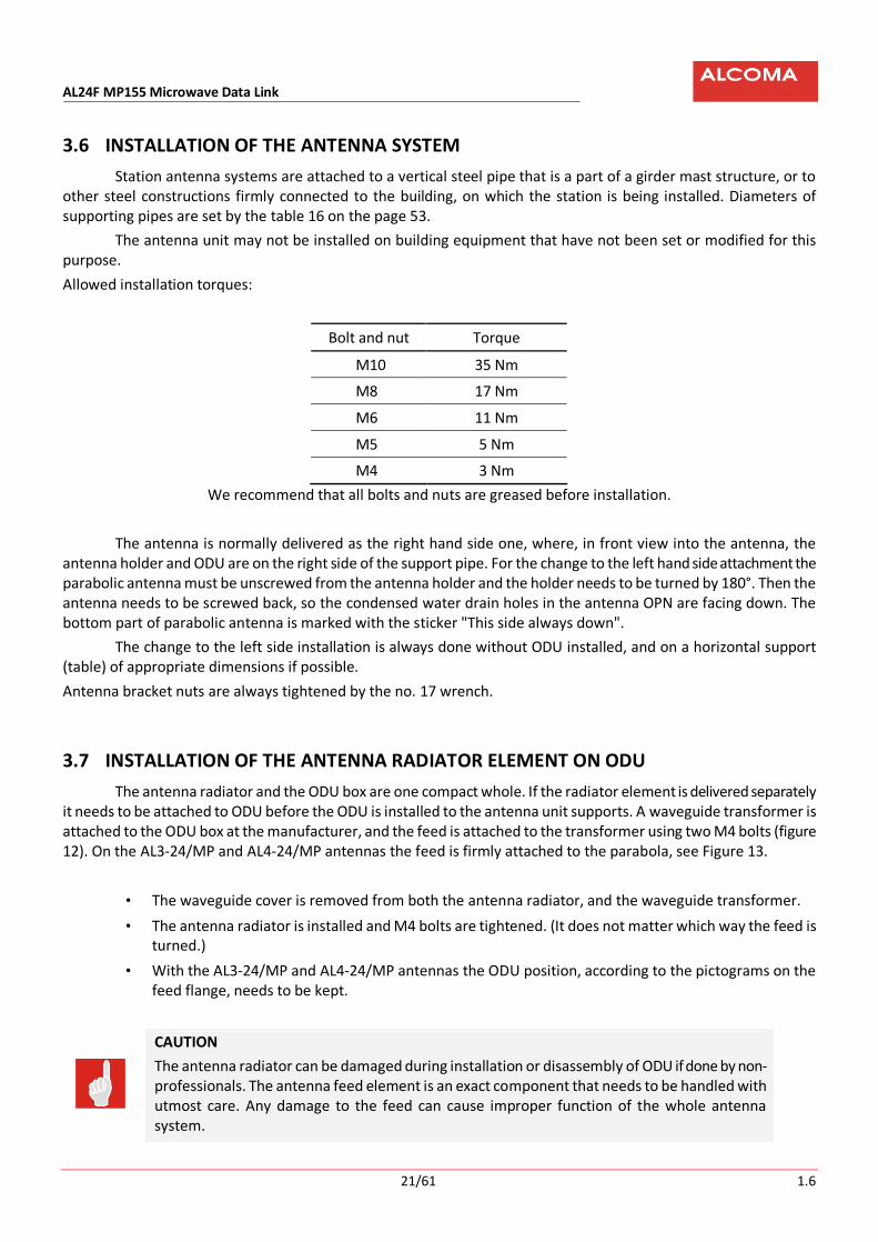
Allowed installation torques:
Bolt and nut Torque
M10 35 Nm
M8 17 Nm
M6 11 Nm
M5 5 Nm
M4 3 Nm
We recommend that all bolts and nuts are greased before installation.
The antenna is normally delivered as the right hand side one, where, in front view into the antenna, the antenna holder and ODU are on the right side of the support pipe. For the change to the left hand side attachment the parabolic antenna must be unscrewed from the antenna holder and the holder needs to be turned by 180°. Then the antenna needs to be screwed back, so the condensed water drain holes in the antenna OPN are facing down. The bottom part of parabolic antenna is marked with the sticker "This side always down".
The change to the left side installation is always done without ODU installed, and on a horizontal support (table) of appropriate dimensions if possible.
Antenna bracket nuts are always tightened by the no. 17 wrench.
3.7 INSTALLATION OF THE ANTENNA RADIATOR ELEMENT ON ODU
The antenna radiator and the ODU box are one compact whole. If the radiator element is delivered separately it needs to be attached to ODU before the ODU is installed to the antenna unit supports. A waveguide transformer is attached to the ODU box at the manufacturer, and the feed is attached to the transformer using two M4 bolts (figure 12). On the AL3-24/MP and AL4-24/MP antennas the feed is firmly attached to the parabola, see Figure 13.
• The waveguide cover is removed from both the antenna radiator, and the waveguide transformer.
• The antenna radiator is installed and M4 bolts are tightened. (It does not matter which way the feed is turned.)
• With the AL3-24/MP and AL4-24/MP antennas the ODU position, according to the pictograms on the feed flange, needs to be kept.
CAUTION
The antenna radiator can be damaged during installation or disassembly of ODU if done by non-professionals. The antenna feed element is an exact component that needs to be handled with utmost care. Any damage to the feed can cause improper function of the whole antenna system.

AL24F MP155 Microwave Data Link
22/61 1.6
3.8 RADIO LINK INSTALLATION
THE RADIO RELAY link AL24F MP155 USES CROSS POLARIZATION
ODU A is set with the opposite polarization than ODU B
(e.g.: ODU A horizontal – ODU B vertical polarization, or
ODU A vertical – ODU B horizontal polarization)
3.8.1 The AL2-24/ME antenna type
Figure 14 The AL2-24/ME antenna installation (also for the AL1-24/ME antenna)
• The antenna radiator element is attached to the outdoor unit (ODU)
• The antenna radiator element is inserted into the antenna using the center guide ring.
• Profiles for antenna and ODU attachment are attached to the parabola (do not tighten).
• ODU is attached to the profiles for attachment of the antenna and ODU (do not tighten). the angle of ODU depends on the used polarization. ODU may not be turned down with its handle!
• Gradually tighten the bolts that hold the parabola and ODU to the profile (figure 14)
3.8.2 The AL4-24/MP antenna type
Bolts M8 vertical pointing
Pipe ø 50 mm
Parabola
OPN
Parabola & ODU holder
Nuts M10 horizontal pointing
ODU
Radiator

AL24F MP155 Microwave Data Link
23/61 1.6
Figure 15 The attachment of the AL4-24/MP antenna holder (also for the AL3-24/MP antenna)
3.8.3 The AL2-24/MPS antenna type
Figure 16 The attachment of the AL2-24/MPS antenna holder (also for the AL1-24/MPS and AL3-24/MPS antennas)
Nuts M10 (allow for vertical pointing)
Bolts M6 Imb.
Mounting pipe ø 90 ÷ 115 mm
Nuts M10 (allow for horizontal pointing)
Nuts M10 (fine adjustment antenna in horizontal direction ±7°)
Nuts M10
Nuts M10 (fine adjustment antenna in vertical direction ±15°)
Antenna MPS
Mounting plate
Bolts M8 imb. 2x
Radiator
ODU
Grounding point
Nuts M10 4x allow for horizontal pointing

AL24F MP155 Microwave Data Link
24/61 1.6
3.8.4 The AL4-24/MPS antenna type
Figure 17 The attachment of the AL4-24/MPS antenna holder
The attachment of ODU with antenna must be sufficiently rigid to withstand wind acting on the ODU without making the link to point in a wrong direction. These forces are primarily caused by the front wind resistance of the microwave antenna.
The ODU box is installed with the outlet of connection cable pointing down with the vertical polarization or to the side with the horizontal one. It is never installed with the outlet pointing up.
Possible disassembly can be performed without affecting the connection pointing direction.
For easy pulling up of ODU with the ME antenna unit type to a mast, a support pipe with the Ø 50 mm that is approx. above the center of gravity of this system can be used. The parabolic antennas AL3-24/MP and AL4-24/MP are equipped by a lifting eye for this purpose.
Please note that, according to the Safety Office Public Notice no. 324/90 Coll. About safety of work and technical equipment during construction, workers must be equipped by PPE, especially a hard hat, during work on masts and in their proximity.
Firm tightening of all connections of an antenna system must be checked after installation. We especially note the tightening of the antenna unit brackets to the antenna support pipe and of the bolts that secure the vertical setting.
Fine vertical adjusting ±15°
Lifting lug
Bolts M10 4x
Nuts M10 allow for vertical pointing
Nuts M10 (allow for horizontal pointing)
Grounding point
Spacing structure 2x
Fine horizontal adjusting ±6°)

AL24F MP155 Microwave Data Link
25/61 1.6
3.9 GROUNDING
CAUTION
The antenna support pipe, antenna system, and the ODU box must be properly connected and grounded with regard to discharges of atmospheric energy.Always refer to local valid standards. and regulations.
Figure 18 The terminal grounding
A support pipe in a stand or lattice mast must be grounded by a steel galvanized wire or a copper wire with a cross section of at least 50 mm2. Also the ODU box and the antenna system must be grounded, best by a copper rope with the cross section of at least 14 mm2 that is ended by a cable eyelet. The brass bolt M8 with the grounding rope eyelet is screwed into the marked hole at the bottom of ODU that is placed under the connection cable grommet.
The antenna system grounding points for the AL1-24/ME and AL2-24/ME antennas are common with ODU MP3. The grounding points of the AL3-24/MP and AL4-24/MP antennas are at the bolts for attaching the equipment to the parabolic mirror. The grounding points of the antenna system equipment of the antennas AL1-24/MPS, AL2-24/MPS, and AL3-24/MPS are on the holder of the antenna unit. The grounding points of the antenna system equipment for the AL4-24/MPS antenna are on the antenna attachment under anchoring of the azimuth tightener (figure 17) and on reinforcing antenna ribs.
This whole equipment should be, if possible, located in the space that is protected by lightning traps against direct lightning strike. If this cannot be guaranteed even through installation of additional traps, then other corresponding modifications must be performed according to the ČSN EN 62305-4 (Protection against lightning) standard and after consultation with a professional.
Also grounding of the shielding of the connecting cable ALSx - ODU just before entering a building must be made by a copper rope with the same cross section of at least 14 mm2.
The protected terminal box ALSx in a building is grounded by a copper rope with the cross section of at least 5 mm2 with cable eyelets. This cable should be connected to the marked M4 pin on the front side of ALSx.
Lighting conductor
ODU
Cable S STP Cat7
Grounding cable (Cu, min. 50 mm2)
Grounding cable (Cu, min. 5 mm2)
Circ
uit
brok
er B
2A
Lighting arrester
Surge protector
Mai
ns o
utle
t
Power supply
Grounding cable (Cu, min. 14 mm2)

AL24F MP155 Microwave Data Link
26/61 1.6
3.10 MANIPULATION WITH THE USER SPACE COVER
The user space cover enables access to the user interfaces for connection and diagnostics of ODU only. This
eliminates a possibility of undesirable interference into other ODU parts. The cover is attached by 2 M6 bolts that can be unscrewed by an Allen wrench no. 5. One of the bolts can be
only partially loosened, which ensures attachment to the box during manipulation with the cover. Retightening of this bolt in open position enables locking of the lid in any position.
Since the user buses are located in the inside hermetically enclosed space of the box, the lid is provided with
a gasket. To protect the gasket from damage, please rigorously keep the safety notice specified below.
Figure 19 Manipulation with the user space cover
Warning
The bolt that ensures attachment of the cover during manipulation must be loosened at least by 1.5 to 2 turns during moving of the cover. In case that the bolt is tightened during moving of the cover more or completely, the gasket is sliding over the box sharp edges that can damage the gasket seriously.
Allow screw for 1,5 ÷ 2 round

AL24F MP155 Microwave Data Link
27/61 1.6
3.11 INSTALLATION OF INTERCONNECT CABLE
We recommend using the shielded cable for outside use by ACOME, type Cat 7 S-STP, or the type Telco 100 W 4*ISTP from Belden Wire, with four pairs of conductors for the connection of the terminal box ALSx and the station AL24F MP155. The cable is led into the link box through a sealing grommet that prevents penetration of climatic humidity from the surroundings and shows sufficient shielding necessary for keeping of electromagnetic compatibility of the whole device at the same time.
The connection cable must not be mechanically loaded. It has to be protected by a flexible electric installation pipe, especially in the outside environment, and attached so the mechanical loading is out of the question. We recommend using the electric installation pipe type HFX 16 by Dietzel Univolt.
It is necessary to keep a minimum curvature during installation and attachment of the cable. The critical spot, especially for vertical polarization, is at the outlet of the connection cable from ODU.
Alcoma completes the radio relay system deliveries by the modified cable of the type Cat 7 S-STP from ACOME. Additional outside insulation of the cable increases its climate resistance and also resistance against the sun UV radiation.
The procedure during installation of ACOME cable type Cat 7 S-STP
(Identical for the protected terminal box and ODU)
• The cover of the protected terminal box is removed using a Phillips screwdriver (figure 22) or the cover of the terminal box space in ODU is opened using an Allen wrench no. 5 (Figure 6).
• The pull-over nut and the sealing grommet are placed over the cable. The top 25 cm of PVC cable cover from the cable end will be removed. The silk guiding thread also needs to be cut.
• The shielding has to be compressed a little, and the conductors need to be cut by about 2 cm. Thus created overlapping shielding will be twisted together.
• The bottom washer, spring washer, and the top washer (in this order) will be pulled over the cable and pushed against the PVC cable cover.
• The twisted shield will be untwisted and released somewhat. Then it will be pulled over the washers on the cable and shortened at the bottom washer (figure 20). No wire of the shielding must go over the bottom washer, in order to tighten the sealing grommet by the pull-over nut well on the cable, and thus seal the grommet properly.
• Shielding of individual pairs will be removed all the way to the turned over top braiding.
• The cable will be inserted through the grommet, and the pulled-over nut will be completely tightened.
• The individual pairs will be divided to the internal Krone connectors that are color coded and numbered on the PCB sticker according to the color codes (for the Cat7 S-STP cable), or numbers (for the Telco 100 Ω 4*ISTP code).
• The individual conductors will be connected using the pusher knife for Krone connectors. The conductor insulation is not removed. It automatically cuts through by the knife connector contacts during installation. The conductors are automatically cut to necessary length at the same time. The cutaway ends must be removed. That is why individual conductor lengths must be sufficient in order to be able to hold the cut off ends in hand during cutting into the connector. Removing them will prevent possible defects.
• The cable installation will be finished by the reinstallation of removed cover. The attachment screws are tightened by a Phillips screwdriver or an Allen wrench.

AL24F MP155 Microwave Data Link
28/61 1.6
Figure 20 The grommet installation
If a customer uses a different cable than the recommended type Cat 7 S-STP by ACOME, the installation is similar. If the cable has separate shielding for each pair of conductors, then the shielding must be connected according to the marking on the Krone connectors. In cables with only one shielding cable taken out the shielding is connected to any shielding pin.
Corresponding after installation tightness of the grommet must be ensured for these customer selected cables too.
CAUTION
It is not allowed to unscrew the grommet from the ODU wall under any circumstances. This grommet is hermetically sealed and this seal would be damaged during disassembly.
Caution! Do not loose washers and a spring ring if you straighten the bent shielding of the connection cable during disassembly of the cable.
Figure 21 Finished assembly of the connection cable Cat7 S-STP
Folded top braid connecting cable
Contact spring ring
Sealing gland
Top plate Bottom plate Cap nut PVC cable cover

AL24F MP155 Microwave Data Link
29/61 1.6
3.12 EXPANSION OF ALS3
In places with operation of more data links ALCOMA AL24F MP155, the standard 19“ 1U protected terminal box offers a possibility to connect up to three independent stations (terminal box of the ALS type). However, unless occupation of the positions 2 and 3 is agreed ahead of time with the manufacturer, the ALS3 box is set for one station only during its manufacture and the remaining two positions are unoccupied.
The particular box design has been selected considering easy expansion to second and third stations without interruption of the already installed station for longer time and disconnection of the station. The ALS3 kit with the type designation 121/316*14 with all necessary components is delivered to expand (add to) the free positions.
CAUTION
The protected terminal box ALS is not compatible with the protected terminal box ALM
Instructions and Recommendations
All safety measures concerning installation of links, or indoor ALCOMA units, specified in other chapters are valid for expansion of ALS3 too.
In order to keep the down time of the operated link as short as possible, we recommend having the connection cable of the new station to ODU prepared and the connection thought out.
Figure 22 The removal of the ALS3 cover
Work procedure
• It is necessary to switch off the outside power before installation.
• After the ALS3 is removed from the 19“ installation cabinet remove the cover by loosening of 6 M3 bolts (see figure 22) by two or three turns, and remove it by lifting and shifting of the back part.
• Remove the front panel plug (terminal box positions are occupied in sequence from the left - front and top view figure 23).
• First install the connection cable to ODU grommet, power connector with jumper, switch, and finally attach the printed circuit board ALS3 by five M3 bolts (all is included in the kit).
• Connect the supply conductors with correct polarity figure 23, or according to already installed ALS3.
• Close the protected terminal box ALS3 by the cover by opposite procedure as used while opening.
• After function testing install the whole protected terminal box to the 19“ installation cabinet.
These 3 screws (and3 symmetrically on the left side) should be allowed
Holes for Real mounting of the connecting cable
Clamp a 19“ housing

AL24F MP155 Microwave Data Link
30/61 1.6
Figure 23 The fully occupied ALS3
Figure 24 The protected terminal box ALS1
3.13 BEFORE PUTTING THE RADIO LINK INTO OPERATION
Before putting the radio link into operation the user must verify, whether he has available documents certified by the distributor that verify that the product is in safe condition.
The manufacturer delivers “Measuring and Testing Protocol” together with the radio link, based on a special request, where basic electrical parameters measured during activation and adjusting of the connection are specified.
1st link 2nd link 3rd link
Grounding point ALS3
Power suply 48 V 1st link
Power supply 48 V 2nd link
Power supply 48 V 3rd link

AL24F MP155 Microwave Data Link
31/61 1.6
3.14 ACCESSORIES
Based on customer wishes we can deliver all accessories necessary for installation and service of the radio relay links AL24F MP155:
• interconnect cables
• KRONE pusher knife
• Lockable 19“ standard installation cabinets
• For the attachment of antenna systems and outdoor units:
o High and low stands ∅ 76 mm a ∅ 102 mm.
o Side and outside brackets
o Brackets for walls and poles
o Special brackets according to customer wishes or needs
Mechanical constructions that show requested strength, rigidity, and atmospheric resistance, and that it can be used according to actual needs.
• DC Power supply with requested characteristics.
• Overvoltage protection for the power supply.
• Cables to connect monitoring PC

AL24F MP155 Microwave Data Link
32/61 1.6
Cnnection cableS-STP Cat7
–
= 48 V
LINE2Eth
LINE3Eth
TX RXTX RX
Function AUTO MDIX
ODUAL24F MP155
Function AUTO MDIX
1 8 1 8
Protected blocksALSx
LINE3Eth
Default jumpersettings:
JP1B, JP2B, JP3B, JP4B
RXTX
LINE2Eth
TX RX
–
Power supply ODU= 48 V LINE 3LINE 2
Eth1 8
Eth1 8
100R
100R
100R
100R
1 81 8
A
B
A
B
JP1 JP2
A
B
A
B
JP4 JP3
Figure 25 Connection of the connecting cable
AL24F MP155 Microwave Data Link
33/61 1.6
4. SETTING OF THE RADIO LINK AND ITS COMMISSIONING Installation and commissioning of the radio relay AL24F MP155 radio link can be performed by the
manufacturer or by a company authorized by him only. The installation can be performed by connecting to a power grid, whose technical condition and manner of protection against electric current injury meets conditions of the ČSN 33 2000-4-41 standard and related regulations. The user must verify whether the ODU supply voltage agrees with the output voltage of a power supply. Electric power network, to which the product will be connected, must be initially inspected according to the ČSN 332000 2000-6-61 standard. If using of extension cables is absolutely necessary, then these cables must be routed in the way that would prevent their damage, overheating, or possible injuries to personnel (by tripping).
For reasons of achieving high operational reliability, parameter stability and long life the units (even enclosed in a cabinet) may not be placed near heat, water, dust, or vibration sources etc.
The ALCOMA ODU units do not contain any adjustment or tuning elements that would have to be modified during commissioning by customers. The units are delivered tuned and tested. Removal of possible defects and failures within the warranty period is done by the manufacturer or a company authorized by the manufacturer. Any manipulation with adjustment elements is prohibited. Any unprofessional interference with the equipment, especially manipulation with adjustment elements, voids the warranty.
CAUTION
An outdoor unit and a protected terminal box must be properly connected to a protection cable, and grounding must be performed due to atmospheric electricity charges. (ČSN 33 4010 - Communication line and equipment protection against atmospheric overvoltage and overcurrent).
Changing of jumpers in ALSx can be done only by personnel instructed at the manufacturer.
In case of commissioning after long term storage (in order of months) the actual time needs to be checked about 10 minutes after switching on. Data are backed up by a high capacity capacitor.
4.1 ANTENNA POINTING
Pointing of radio link is done by adjusting antennas to the maximum level of received signal. The pointing of a radio link needs to be done in the horizontal and vertical directions systematically and very carefully in several steps. The pointing is done gradually at both stations. It is not possible to point both stations at the same time.
Pointing of a radio link needs to be done during stable sunny weather (dry air). If there are meteorological fluctuations along the route (rain, snow) that cause sudden changes of the level of received signal, then it is better to interrupt the pointing a wait for better weather.
At the beginning of pointing both opposite stations must already be roughly adjusted and switched on in order to pick up their signals. This is difficult with long hops where bigger gain antennas with consequently narrower radiation diagrams are used.
To make pointing easier, ODU has the built in acoustic signalization of the size of received signal level that can be switched on by a rotary switch at the user space (Figure 6).

AL24F MP155 Microwave Data Link
34/61 1.6
Figure 26 Pointing
Pointing Procedure:
• Loosen all M10 bracket nuts of the antenna support by no. 16/17 mm and 13 mm wrench.
• Using an Allen wrench no. 5 loosen and flip up the cover on the ODU box (see the chapter 3.10 on the page 26).
• After removing the BNC connector cover at the bottom part of the ODU box connect DC voltmeter set to the min. range of 5 V to it. It is more advantageous to use an analog voltmeter for easier reading while searching for a maximum value. (In a pinch you can connect a DC ampere meter with the min. range of 5 mA).
• The rotary switch needs to be moved to the pointing position. Base tone of acoustic signalization sounds, which by its pitch (not intensity) corresponds to the strength of received signal. A deep (base) tone sounds when the unit does not receive any signal, or the signal is very weak. The tone (voltage on URSSI) increases in jumps, since it is digitally linearized.
After switching the rotary switch, it is good to wait with reading of URSSI about 5 s for the ATPC system to stabilize (if switched on).
CAUTION
The rotary switch in the position Pointing also switches off a transmitter of the local station. Switching off of the output also in the remote station by the rotary switch can be used to find a level of interference signals (background noise) on given channels.
Rough Adjustment
The rough adjustment can be done “by eye” using binoculars rested against the antenna. If the visibility is bad, or distance is too long, you need to determine the azimuth first using a compass.
Caution! Compass measurement accuracy is limited by steel mast construction! The rough pointing should have a variation of max. ±5° from the ideal antenna connecting line.
We are trying to attain a signal of the opposite station by horizontal turning of the antenna by ±30° from assumed direction.

AL24F MP155 Microwave Data Link
35/61 1.6
The vertical setting is changed gradually, and the scanning in the direction of reception is done by horizontal turning. We do not recommend changing both directions at the same time. The maximum reception is set approximately.
Figure 27 The AL2-24/ME antenna pointing (also for the AL1-24/ME antenna)
Figure 28 The pointing of the AL2-24/MPS antenna (also for the AL1-24/MPS and AL3-24/MPS antennas)
Nuts M10 allow for horizontal pointing
Screw M8 allow for vertical pointing
±180°
±25°
Nuts M10 4x allow for horizontal pointing
Nuts M8 4x allow for vertical pointing
±25°
±180°

AL24F MP155 Microwave Data Link
36/61 1.6
Fine horizontal pointing
• Loosen all M10 antenna support bracket nuts using no. 16/17 wrench. It is better to loosen the nuts without unnecessary play that would later cause a loss of exact direction after tightening. With the MPS antenna type it is better to use an auxiliary bracket that prevents the antenna sliding along the support pipe.
• Turning of the parabolic antenna by ±15° you can find the main lobe on the connected DC voltmeter and in the beginning of measurement also both side lobes of the antenna radiation characteristic.
• Setting of the maximum level on the main lobe.
• After you set the maximum level on the main lobe, fix the antenna in the found direction by tightening the antenna support M10 bracket nuts.
Vertical Pointing
• ME type antennas
§ Loosen the fixation M10 bolts without unnecessary play that would cause loss of the proper direction after tightening.
• MPS type antennas
§ Loosen the nuts of the M10 fixation bolts of the antenna support. The fixation bolts are secured against turning and it is not necessary to hold them.
• By turning of the parabolic antenna you can find the main lobe on the connected DC voltmeter and in the beginning of measurement also both side lobes of the antenna radiation characteristic.
• Set the maximum level on the main lobe.
• After you set the maximum level on the main lobe, tighten MPS type antennas by tightening of fixation bolt nuts, and ME type antennas by tightening bolts at found positions.
Figure 29 The AL3-24/MP antenna pointing (also for the AL4-24/MP antenna)
Nuts M10 (allow for horizontal pointing)
Nuts M10 (fine horizontal adjustment ±7°)
±15°
±7°
Nuts M10 allow for vertical pointing
Nuts M10 (fine vertical adjustment ±15°)

AL24F MP155 Microwave Data Link
37/61 1.6
Figure 30 The radio link pointing with the AL4-24/MPS antenna
In order to reach the direction stability and resistance against outside loads the antennas AL3-24/MP, AL4-
24/MP, and AL4-24/MPS, use a different way of attachment in comparison with smaller antennas. There is a support bracket that prevents sliding of the antenna down along a pipe at the bottom part. There is a special set of brackets above this one for a fine setting in the horizontal and vertical directions (figure 15, figure 17, figure 29, and figure 30).
The pointing of radio link with the AL4-24/MP antenna (∅ 1.20 m)
• The vertical setting bolts are loosened for the vertical pointing. For horizontal pointing then the support bracket bolts.
• During pointing of an antenna in the horizontal direction position of the antenna is roughly set and the M10 bolt on the main bracket are tightened. The antenna position for the maximum signal is set by the M10 nuts on the rotating bracket.
• All M10 bolts on the horizontal pointing brackets are tightened.
• During pointing of the antenna in vertical direction the vertical pointing bolts are loosened. The antenna is set to the highest signal level by a connecting rod with M10 nuts.
• All M10 bolts are tightened to secure the antenna vertical position.
Fine verticaladjustement ±15°)
Nuts M10 (allow for horizontal pointing)
Nuts M10 (allow for vertical pointing)
Fine horizontal adjustement ±6°) ±6°
±15°

AL24F MP155 Microwave Data Link
38/61 1.6
The pointing of connection with the AL4-24/MPS antenna (∅ 1.20 m)
• The vertical setting bolts are loosened for the vertical pointing. For horizontal pointing then the support bracket bolts.
• During pointing of an antenna in the horizontal direction position of the antenna is roughly set and the M10 bolt on the main bracket are tightened. The antenna position for the maximum signal level is set by a tensioner.
• All M10 bolts on the horizontal pointing brackets are tightened.
• During pointing of the antenna in vertical direction the vertical pointing bolts are loosened. The antenna is set to the highest level of the received signal by a tensioner.
• All M10 bolts are tightened to secure the antenna vertical position.
Figure 31 Main lobe diameter with different lengths of connection
Remark: The basic range for setting of the vertical direction is ±15°.
The pointing procedure in both horizontal and vertical directions must be repeated several times to make sure that the best maximum of the radiation characteristic was found. The opposite station antenna needs to be final adjusted the same way. It is necessary to prevent sliding of the parabolic antenna along the support pipe during horizontal pointing.
Main lobe diameter: 14 m Connection lenght: 1 Km Antenna: AL4-24/MP Building height: cca 140 m
Main lobe diameter: 74 m Connection lenght: 5 Km Antenna: AL4-24/MP Building height: cca 140 m
Receiver Receiver Main lobe diameter Main lobe diameter

AL24F MP155 Microwave Data Link
39/61 1.6
4.2 CHANGE OF POLARIZATION
The polarization change can be performed without loosing the link direction just by turning ODU by 90° that is done as follows:
ME type antennas
• Unscrew 4 M6 Allen screws that hold ODU to the supporting ODU profiles for attachment of the antenna and ODU.
• Turn the ODU together with the antenna radiator element by 90°. Turning direction is not important. However, for horizontal polarization the connecting cable output must point down and for vertical polarization to the side.
• Using the center guide ring insert the ODU into the antenna.
• The ODU profile attachment bolts are screwed in.
MP type antennas
• Unscrew 4 M6 Allen screws that hold ODU to the supporting ODU profiles for attachment of the antenna and ODU.
• Unscrew 4 M5 bolts that hold the feed element flange in the parabola, the feed is turned and then attached to the parabola again.
• ODU is turned by 90°. Turning direction is not important. However, for horizontal polarization the connecting cable output must point down and for vertical polarization to the side. The ODU position must be maintained, in order to agree with the pictograms on the feed flange (figure 13 on the page 20).
• ODU inserted on the feed element flange and placed into the parabola spacers.
• The ODU attachment bolts are screwed into the spacers.
MPS type antennas
• 4 Allen M6 screws that attach the ODU to the MP3 antenna support are unscrewed (figure 16 on the page 23).
• Turn the ODU together with the feed element by 90°. Turning direction is not important. However, for horizontal polarization the connecting cable output must point down and for vertical polarization to the side.
• Using the center guide ring insert the ODU into the antenna.
• The ODU profile attachment bolts are screwed in.
The used polarization for left hand or right hand ODU installation can be determined according to the position
of the connection cable outlet. If the outlet points down, the used polarization is horizontal, if to the side, then it is vertical.

AL24F MP155 Microwave Data Link
40/61 1.6
Figure 32 The setting of polarization for the AL24F MP155 station
Checking of Pointing
The value of received level can be determined by direct reading in the ASD monitoring program or by calculation using the calibration graph for RSSI. The RSSI voltage can be measured at the BNC connector without necessity to adjust the rotary switch.
To check for the proper pointing, it is good to calculate the signal level that should be measured. The maximum allowed deviation between the calculated and measured signal levels is ±3 dB. If the negative deviation is higher the connection needs to be better pointed.
The noise level on the receiving channel needs to be checked while the opposite station is switched off. The minimum requested separation of the noise level from the received signal is 20 dB. The opposite station can be switched off remotely using the ASD monitoring program.
• Place the pointing switches to the 0 position (in both connection stations) after pointing is finished.
• Screw the user space cover back on.
• It makes sense to write down all measured values for checking later.
Frequent problem during antenna pointing is pointing to an antenna side lobe. The antenna can then show a sharp peak, however, the signal level is about 20 dB lower. Therefore it is important to turn the antenna during pointing at least ±10° in horizontal and vertical directions, and catch the main and both side lobes of the antenna radiation diagram. We need to realize that the antenna radiation diagram is three dimensional, and if we make a setting error in one direction (for example vertical one), then it is possible to receive only the side lobes in the other direction, and they do not even need to be equal due to route conditions.
The radiation characteristics of parabolic microwave antennas are shown in the measurement protocols for ALCOMA antenna type approval. ALCOMA will provide copies of these protocols upon request.
Horizontal polarization
Vertical polarization
Horizontal polarization

AL24F MP155 Microwave Data Link
41/61 1.6
0
0,5
1
1,5
2
2,5
3
3,5
4
4,5
-80 -70 -60 -50 -40 -30 -20
Pin[dBm]
U R
SSI[V
]
Figure 33 The RSSI calibration graph
4,125

AL24F MP155 Microwave Data Link
42/61 1.6
4.3 CONTROL CALCULATION
The following relationship is valid for the calculation of a level at the output of the receiving antenna, i.e., at the input of the microwave receiver:
Pin[dBm] = Pvys[dBm] + GantV[dB] + GantP[dB] – A0[dB]
where: Pvys[dBm] is the transmitted output of the opposite station
GantV[dB] is the transmitting antenna gain
GantV[dB] is the receiving antenna gain
A0[dB] is the free environment attenuation
The following relationship is valid for the attenuation of free environment during good climatic conditions (without rain and fog):
A0[dB] = 92.44 + 20 log( d[km] ∗ f[GHz] )
where:
d[km] distance between antennas
f[GHz] used frequency.
The relationship for attenuation in the free environment with using of the medium frequency of 24.125 GHz can be reduced, so that it is valid in the range from 24.000 to 24.250 GHz with sufficient accuracy:
A0[dB] = 120.09 + 20 log(d[km]).
After substitution into the original formula, assuming that the transmitted output of the opposite station is Pvys = 0 dBm, we will get:
Pin[dBm] = GantV[dB] + GantP[dB] – 120.09 – 20 log(d[km]).
The calculated values Pin can be compared with the values measured by using the RSSI calibration graph, or by direct reading of the values given by the monitoring program.
If the constructed connection has a partially disturbed first Fresnel zone then the attenuation due to the disturbance cannot be higher than -6 dB in comparison with a free path. The optical visibility along the antenna axis has to be maintained in any case. In the opposite case retranslation would have to be used, and the critical spot would have to be circumvented.
The additional attenuation of the path given by the disturbance of the 1st Fresnel zone by a single terrain obstacle with a sharp peak is represented by the graph (figure 34). The graph shows the relative height of the obstacle z related to the ellipsoid radius of the 1st Fresnel zone. The value z = 0 represents the edge that touches the optical connection, i.e., covering of 50% of the ellipsoid of the 1st Fresnel zone. More details can be found in the book by Pavel Pechač and Stanislav Zvánovec: "Bases of wave propagation for planning of land radio relay links (Základy šíření vln pro plánování pozemních rádiových spojů)", published by BEN in 2007.

AL24F MP155 Microwave Data Link
43/61 1.6
Přídavný útlum zastínění
0
5
10
15
20
25
-2,0 -1,5 -1,0 -0,5 0,0 0,5 1,0 1,5 2,0z[-]
Ld[dB]
Figure 34 The approximation of additional attenuation behind an obstacle.
4.4 DIRECT CONNECTION OF A MONITORING PC
Normally the communication of the monitoring PC with the AL24F MP155 station takes place through data connection (TCP/IP protocol) over Ethernet, where both user data, and the monitoring data are transmitted. If this connection is not possible the monitoring PC with installed and running, ASD program can be connected directly to ODU through an RS-232 interface. The interface connector PFL10 is located on the ODU motherboard. The connector is accessible after opening of the ODU box cover. All standard signals with the RS-232 interface signal level are brought onto this connector, while the signal ground of this interface is galvanically connected with the ODU ground.
0
-1
1 z
b
Additional attenuation behind an obstacle

AL24F MP155 Microwave Data Link
44/61 1.6
A cable connected according to the following figure can be used for this connection:
Figure 35 The direct connection of the monitoring PC
If the PC frame is galvanically connected with the power grid, the direct monitoring of the PC to ODU is not recommended. With regard to possible transfer of noise signals from the ODU unit to the power grid and the other way round this connection is only an emergency solution acceptable for a short time.
For service purposes Alcoma delivers a cable ended on one side by the Cannon 9F connector and on the other by the Cannon 9M and PFL10 connectors, which connects the DCD, RX, TX, DSR, DTR, RTS, and CTS signals. The cable is intended for a temporary connection of the monitoring PC with the monitoring processor in ODU.
The minimum 4 wire connection requires the RX, RTS, TX signals and the signal grounding, i.e., using of no. 3, 4, 5, and 9 pins.
User interface
PC serial port
PC surveilance
Caution: Pins 7-4 and 8-9 may or may not be a cable connected

AL24F MP155 Microwave Data Link
45/61 1.6
5. OPERATION INSTRUCTIONS
5.1 OPERATION
The radio relay link AL24F MP155 does not require any service or maintenance during operation.
The radio relay link AL24F MP155 can be remotely monitored by the ASD program that is intended for the management and diagnostics of the ALCOMA radio relay links using a monitoring PC during operation. All actual states, events and instructions are shown in individual windows in the arrangement according to separate functions or meanings (local station window, alarm history, station configuration, etc.). The monitoring system enables diagnostics of the radio links and both local and remote ends of the connection. The monitoring system is not necessary for the link transfer function itself (the link can be operated even without monitoring elements). However, monitoring is giving us diagnostic possibilities that simplify checking of the proper link function, or localization of possible defects. Detailed description and use of the ASD monitoring program is in a separate manual.
Figure 36 Main windows of the ASD program
According to the ČSN 33 1500 standard regular inspections and checks of safe status during operation are
recommended once every 24 months. (see the chap. 6). Inspections and checks are recommended to be performed by the supplier professional service.

AL24F MP155 Microwave Data Link
46/61 1.6
5.2 SPECTRAL ANALYZER
The following figure 37 shows the function of the spectral analyzer.
• To show channel numbers and a relayed range it is necessary to read in the corresponding frequency table in the ASD monitoring program (Option / Channel Table).
• Representation of the received spectrum for local and remote ODUs. • Print will print a graph of the received signal spectrum in the whole frequency range. • Scan will start measurement of the received signal spectrum (temporary interruption of data transmis-
sion). The measured values will be written into memory, from where it can be recalled anytime. • Reload is a display of last measurement of the received signal spectrum values. • Close will close the spectral analyzer window.
Figure 37 The spectral analyzer
CAUTION
There will be a temporary interruption of data transmission during the start of measuring of received signal spectrum (Scan). (The connection is scanned for receiving frequencies of the frequency range.) Spectral data from the previous measurement will be overwritten.
Local and remote switching of ODU Frequency band Channel number
Retrieve previous measurement
Spektrum measurement

AL24F MP155 Microwave Data Link
47/61 1.6
5.3 EMERGENCY CONDITIONS
Emergency conditions are such states and equipment demonstrations that can cause property damage and endanger health and safety of persons. These states and demonstrations include: damage of covers, connection cables, loosening of the equipment mechanical connections, strong corrosion, excessive heating, smell, smoke, etc.
WARNING
In case that any emergency conditions are observed, the operator must immediately remove them.
5.4 REPAIRS
CAUTION
Equipment repairs can be performed only by personnel that have necessary professional qualifications and have been instructed at the manufacturer according to the microwave data link AL24F MP155 service manual. Operation personnel are prohibited from opening covers, breaking seals and unprofessionally interfering with the equipment.
After each product repair or discovery of emergency condition there must be demonstrable inspection of the safe product condition. This inspection must be recorded and signed by an authorized person. This record must be handed, together with the repaired product, to the user. The inspection may be performed by personnel qualified at least by Paragraph 5, Notice No. 50/1978 (knowledgeable worker).
Since the current version of the AL24F MP155 link does not support E1 transmission, it is not possible to perform any measurement loop for the purpose of error diagnostics using the ASD monitoring program.
5.5 ENDING OF OPERATION – ECOLOGICAL LIQUIDATION
The product is, from the ecological standpoint, classified as a hazardous electrotechnical object. After its service life it is, according to Law No. 7/2005 (Waste Law), an electronic waste, and as such it must be handed over to the appropriate enterprises that perform recycling of old electronic products. The product may not be liquidated as general community waste. The ALCOMA Company has concluded a Contract about liquidation of electronic waste with the SAFINA a.s. Company.
In agreement with the Public Notice No. 352/2005, Paragraph 8c, every serial label that is placed on each product shows a graphic symbol of stricken through waste bin that cautions about obligations related to liquidation of electronic waste.
The product transport packaging is made from common recyclable material (paper and polyethylene) marked as such by a label according to the ČSN 77 0052-2 standard.

AL24F MP155 Microwave Data Link
48/61 1.6
6. SAFETY CHECK Each AL24F MP155 radio link is verified within check-out inspection, and its parameters are measured
according to the ČSN 33 1500 standard (Inspection and testing of electrical installations). According to the ČSN 33 1610 standard the ODU of the radio relay link AL24F MP155 is an electrical device of the class B (appliances used in the outside environment), supplied by SELV (Safety Extra-Low Voltage) supply and inside of the unit there is no higher voltage than SELV. The unit allows connection of dead parts by a grounding bolt to a protection circuit that serves also as a protection against overvoltage and overcurrent of atmospheric origin.
In agreement with the ČSN 33 1610 standard the ODU belongs to
• the group B according to its use – appliances used in outside areas
• the class III according to protection – protection against injury by electric current is based on the connection to a SELV supply, with the voltage no higher than SELV.
According to the ČSN 33 1500 standard regular inspections and checks of safe status during operation are recommended once every 24 months. Inspections and checks are recommended to be performed by the supplier professional service.
The following activities are recommended during regular checks and inspections:
• Check of ODU tightness.
• Condition of antenna OPN (protection against icing) cover.
• Status of interconnect cable and its grommets.
• Tightening and lubrication of all attachment bolts and nuts. No construction part can be weakened or damaged by corrosion.
• Checking of grounding connection strength at grounding points and their connection to earth.
• Finding possible damage or changes of the whole system that would require further measures and the verification of safety.
• We recommend measuring and recording the level of received signal.

AL24F MP155 Microwave Data Link
49/61 1.6
7. RADIO RELAY LINK PARAMETERS
7.1 FREQUENCY PLAN
The radio relay link ALCOMA AL24F MP155 works in the frequency range of 24 000 to 24 250 MHz. Radio relay link operation in the Czech Republic is allowed based on the general authorization no. VO-R/10/06.2009-9 (CTO Telecommunication news 7/2007), and in the Slovak Republic based on the general li-cense no. VPR-05/2001 (TU SR 6.8.2001). Microwave links can be operated by physical and legal entities for their own use without any further fees or evidence according to these licenses.
In the specified frequency range the microwave units are tuned according to the frequency plan as it is specified in table 10. The table frequencies are in MHz.
A - band lower half B - band upper half
Channel number
Transmitter frequency [MHz]
Channel number
Transmitter frequency [MHz]
8 24 005,5 8´ 24 195,5
9 24 012,5 9´ 24 202,5
10 24 019,5 10´ 24 209,5
11 24 026,5 11´ 24 216,5
12 24 033,5 12´ 24 223,5
13 24 040,5 13´ 24 230,5
14 24 047,5 14´ 24 237,5
15 24 054,5 15´ 24 244,5
Channel width 7 MHz
A – band lower half B – band upper half
Channel number
Transmitter frequency [MHz]
Channel number
Transmitter frequency [MHz]
4 24 010 4´ 24 200
5 24 024 5´ 24 214
6 24 038 6´ 24 228
7 24 052 7´ 24 242
Channel width 14 MHz
A – band lower half B – band upper half
Channel number
Transmitter frequency [MHz]
Channel number
Transmitter frequency [MHz]
2 24 016 2´ 24 206
3 24 044 3´ 24 234
Channel width 28 MHz
Table 10 The ALCOMA frequency table for AL24F MP155

AL24F MP155 Microwave Data Link
50/61 1.6
The frequency tables of frequency tables are related to the data transmission speed. The frequency range for the transmitters A and B is divided as follows:
Transmitter frequency range
ODU type Min. frequency
[MHz] Max. frequency
[MHz] Duplex
separation [MHz]
AL24F MP155 / A 24 000 24 060 190
AL24F MP155 / B 24 190 24 250 190
Table 11 The frequency range of the AL24F MP155 transmitter
Stations with the frequency range in the sub range A can cooperate with all sub range B frequencies. This setting requires a proprietary frequency table. Further info is in the ASD monitoring program manual. The pair tuning according to channels is usually selected that always shows on one line of table 10.
7.2 MODULATION, THRESHOLD SENSITIVITY AND TRANSFER CAPACITY OF THE CONNECTION
The AL24F MP155 link can be set to various transmission capacities according to used modulation and channel bandwidth. The individual transmission capacities are related to different threshold sensitivities as shown in table 12.
The highest internal transmission speed, including service communication, of the link is 165 Mbit/s.
Total bit speed
[Mbit/s] Modulation
Typical
Threshold sensitivity
for BER = 10-6 [dBm]
Width
of transmitted
spectrum in [MHz]
10 QPSK -87
19 16 -80
25 32 -77
7
17 QPSK -84
39 16 QAM -82
50 32 QAM -78
61 64 QAM -75
72 128 QAM -70
14
34 QPSK -83
77 16 QAM -80
100 32 QAM -75
123 64 QAM -73
158 128 QAM -67
1652 128 QAM -67
28
Table 12 Radio link transmission speeds
2 The transmitted spectrum limited by a mask is used completely.

AL24F MP155 Microwave Data Link
51/61 1.6
7.3 TECHNICAL PARAMETERS
Parameter AL24F MP155
Transmitter frequency - lower band section (/A) - upper band section (/B)
24 000 ÷ 24 060 MHz 24 190 ÷ 24 250 MHz
Minimum channeling tuning step 50 kHz
Channel spacing see table 10
Frequency stability better than ±10 x 10–6
Transmitted output of basic version max. 5 dBm ATPC3
Transmitter spectrum mask ETSI 301 751
Typical threshold sensitivity during BER = 10–6 (max. values are by +3 dB higher than typical values) see table 12
Ethernet user interface 10Base-T / 100Base-TX
Input connectors for Ethernet user lines RJ-45
Interconnect cable protected terminal box - ODU (recommended type S-STP Cat.7 ACOME)
4 pair shielded imp. 100 Ω
Maximum length of interconnect cable4 for 10Base-T for 100Base-TX
250 m 100 m
DC supply voltage on the protected terminal box +36 V ÷ +72 V
Supply input for U = +48 V and 100 m connection cable < 25 W
Table 13 Radio link parameters
Parameter Value
ALS3 terminal box dimensions (w x h x d) 482 x 44 x 138 mm
ALS1 terminal box dimensions (w x h x d) 162 x 44 x 135 mm
ODU dimensions (without antenna radiator and antenna) (w x h x d)
255 x 301 x 133 mm
ODU weight (without antenna and antenna radiator)
5.1 kg
ALS1 weight 0.75 kg
ALS3 weight (with 1 PCB) 1.57 kg
Table 14 Technical parameters
3 The transmitter output is set during manufacturing, so the transmitted output EIRP (i.e., including parabolic antenna gain)
would in the Czech Republic be in agreement with VO-R/10/06.2009-9, and in the Slovak Republic with VPR-05/2001, max. 20 dBm.
4 Including the cable that brings data to the protected terminal strip.

AL24F MP155 Microwave Data Link
52/61 1.6
7.4 ENVIRONMENT
Operation
ODU is intended for stationary use in locations unprotected against climatic conditions. The protected terminal box is intended for stationary use in locations protected against climatic conditions.
Climatic Resistance Surrounding temperature
ALSx from -25 °C to +55 °C Operation capability
ODU from -35 °C to +55 °C
ALSx from -25 °C to +55 °C Guaranteed parameters
ODU from -33 °C to +50 °C
Storage ability ALSx and ODU from -25 °C to +55 °C
Table 15 Operatinal temperature
By operation ability we understand that the radio link can be operated within the specified temperatures, but some parameters can deviate from specified limits. There will be no irreversible or permanent change or damage to units in the specified temperature range.
ALSx and ODU units surrounding environment must not contain aggressive vapors and gases, must have a normal radiation level, and be without vibrations and shocks. All ALSx and ODU units are air-cooled by natural air circulation. They do not contain fans that would suck in dirt from surrounding areas and thus lower the reliability of the microwave link.
The radio link is resistant against effects of wind with speeds of up to 33 m/s (120 km/h) without influence to transmission quality. Reversible changes, i.e., elastic deformation occur up to the wind speed of 56 m/s (200 km/h). Permanent deformation can occur above this threshold, however, without damage to ODU itself.
ALSx can be stacked into a cabinet without forced cooling air flow with the minimum spacing of 15 mm. Moving of ODU and ALSx is possible after disconnecting of the power supply cable and other cables, in other words not while they are in operation.
If used in environment that does not meet these requirements, the user must consult the operational conditions with the supplier technical service.
Transport and Storage
The radio relay link units can be transported only in covered vehicles and the units must be protected against direct weather influence at the same time. They should be transported in suitable (best in original) packaging in order to prevent excessive loads through shaking, vibrations etc., they are not allowed to be dropped. A specific form of transport is a matter of agreement between the manufacturer and the client.
The radio relay units must be stored in dry, partially air-conditioned areas. The range of storage temperatures is -25 ÷ +55 °C, with the relative humidity max. 85 %.

AL24F MP155 Microwave Data Link
53/61 1.6
7.5 ANTENNA SYSTEMS
Parabolic antennas for fixed connection to ODU were developed for the 24 GHz band. The ALCOMA parabolic antennas can be used for horizontal and vertical polarization and left or right hand installation without modifications. All antennas are standard equipped by protection against icing (OPN). The antenna flange is EC-R220. The change of polarization is performed by turning ODU by 90°; see the chapter 4.2, page 39.
Type Compact microwave antennas AL1-24/ME AL2-24/ME AL3-24/MP AL4-24/MP
Parabola diameter ∅ 0.35 m ∅ 0.65 m ∅ 0.90 m ∅ 1.20 m
Antenna gain Gant 36 dB 41 dB 45 dB 47 dB
Main lobe 3 dB ±1.3° ±0.75° ±0.5° ±0.4°
Horizontal antenna setting ± 180° ±7°
Vertical antenna setting ±25° ±25° ±15°5 ±15°5
Weight of compact antennas
5,6 kg 8,3 kg 26 kg 36 kg
Diameter of installation stand6 min. ∅38 mm ∅48 mm ∅60 mm ∅90 mm
max. ∅115 mm
Table 16 The ME, MP antenna parameters
Type Compact microwave antennas AL1-24/MPS AL2-24/MPS AL3-24/MPS AL4-24/MPS
Parabola diameter ∅ 0.35 m ∅ 0.65 m ∅ 0.90 m ∅ 1.20 m
Antenna gain Gant 36 dB 41 dB 45 dB 47 dB
Main lobe 3 dB ±1.3° ±0.75° ±0.5° ±0.4°
Horizontal antenna setting ± 180°
Vertical antenna setting ±25° ±25° ±25° ±10°
Adjustment of supporting pipe to vertical ± 10°
Weight of compact antennas
8.6 kg 15 kg 17 kg 43 kg
Diameter of installation stand6 min. ∅38 mm ∅48 mm ∅60 mm ∅90 mm
max. ∅115 mm
Table 17 The MPS antenna parameters
5 Fine elevation adjustment. 6 Supporting pipe lengths must guarantee sufficient rigidity considering climatic influences of surrounding environment, and
∅38 ÷ 60 mm pipes can be used as lattice antenna mast parts only.

AL24F MP155 Microwave Data Link
54/61 1.6
7.6 REFERENCE RANGE OF THE AL24F MP155 RADIO LINK
The following table shows nominal lengths of the AL24F MP155 link for various communication speeds. For the last mile link (level MG X4 for horizontal and vertical polarization): Transmission output PTX = 20 dBm EIRP
24 GHz range
Output 20 dBm EIRP
50 Mbit/s BW = 14 MHz
32 QAM
100 Mbit/s BW = 28 MHz
32 QAM
159 Mbit/s BW = 28 MHz
128 QAM
antenna 0.35 m 1.4 1.2 0.7
antenna 0.65 m 2 1.7 1
antenna 0.90 m 2.4 2.1 1.4
antenna 1.20 m 2.6 2.3 1.6
Table 18 Ranges of the AL24F MP155 radio link 20 dBm EIRP

AL24F MP155 Microwave Data Link
55/61 1.6
8. MAIN EQUIPMENT DIMENSIONS
8.1 ODU – OUTDOOR UNIT
301
4
75
220
220
255
39
10
133
O79
,8
Figure 38 The ODU main dimensions
8.2 PROTECTED TERMINAL BOX
465
3213
625 440
481
Figure 39 Protected terminal box ALS3

AL24F MP155 Microwave Data Link
56/61 1.6
4413
725 165 21
32
Figure 40 Protected terminal box ALS1
8.3 ANTENNAS WITH ODU
235
500
241
333
220
x 22
0
255
x 25
5
O37
1
Figure 41 Antenna AL1-24/ME

AL24F MP155 Microwave Data Link
57/61 1.6
404
496
235
674
220
x 22
0
O71
7
Figure 42 Antenna AL2-24/ME
329
904496
596
220
220
O99
4
Figure 43 Antenna AL3-24/ME

AL24F MP155 Microwave Data Link
58/61 1.6
3161001
220
220
648748
O12
14
Figure 44 Antenna AL4-24/ME
284
21028
8
287362
O37
1
Figure 45 Antenna AL1-24/MPS

AL24F MP155 Microwave Data Link
59/61 1.6
284
643
220
220
452
527
O71
7
Figure 46 Antenna AL2-24/MPS
286
908
220
518
594
Figure 47 Antenna AL3-24/MPS

AL24F MP155 Microwave Data Link
60/61 1.6
295
1017
822
993
220
O12
21
Figure 48 Antenna AL3-24/MPS

AL24F MP155 Microwave Data Link
61/61 1.6
9. APPENDIX List of figures The block schematic of the AL24F MP155 connection 6 The protected terminal box ALS3, ALS1 7 The profile to attach ALS1 to the DIN box TS35 7 The placement of jumpers on PCB of the ALSx protected terminal box 11 The ODU connection places 12 The ODU user space 14 The Fresnel zone 16 Improper placement of antenna on mounting pipe 17 Proper placement of antenna on mounting pipe 17 The cross polarization of the radio link AL24F MP155 18 The examples of channel and polarization usage in case of more connections in one location 19 Attaching of the feed element to the ODU MP3 20 Attaching of the antenna radiator element to the AL3-24/MP, AL4-24/MP antennas 20 The AL2-24/ME antenna installation (also for the AL1-24/ME antenna) 22 The attachment of the AL4-24/MP antenna holder (also for the AL3-24/MP antenna) 23 The attachment of the AL2-24/MPS antenna holder (also for the AL1-24/MPS and AL3-24/MPS antennas) 23 The attachment of the AL4-24/MPS antenna holder 24 The terminal grounding 25 Manipulation with the user space cover 26 The grommet installation 28 Finished assembly of the connection cable Cat7 S-STP 28 The removal of the ALS3 cover 29
The fully occupied ALS3 30 The protected terminal box ALS1 30 Connection of the connecting cable 32 Pointing 34 The AL2-24/ME antenna pointing (also for the AL1-24/ME antenna) 35 The pointing of the AL2-24/MPS antenna (also for the AL1-24/MPS and AL3-24/MPS antennas) 35 The AL3-24/MP antenna pointing (also for the AL4-24/MP antenna) 36 The radio link pointing with the AL4-24/MPS antenna 37 Main lobe diameter with different lengths of connection 38 The setting of polarization for the AL24F MP155 station 40 The RSSI calibration graph 41 The approximation of additional attenuation behind an obstacle. 43 The direct connection of the monitoring PC 44 Main windows of the ASD program 45 The spectral analyzer 46 The ODU main dimensions 55 Protected terminal box ALS3 55 Protected terminal box ALS1 56 Antenna AL1-24/ME 56 Antenna AL2-24/ME 57 Antenna AL3-24/ME 57 Antenna AL4-24/ME 58 Antenna AL1-24/MPS 58 Antenna AL2-24/MPS 59 Antenna AL3-24/MPS 59 Antenna AL3-24/MPS 60
List of tables The RJ45 connector wiring - user lines Eth2 and Eth3 8 The protected terminal box - cutting box “KRONE“ for the line 2 9 The protected terminal box - cutting box “KRONE“ for the line 3 9 The meaning of jumpers of the protected terminal box ALSx 11 The outdoor unit - cutting box “KRONE“ for the line 2 13 The outdoor unit - cutting box “KRONE“ for the line 3 13 Meaning of LEDs in the ODU user space 14
Description of functions of the rotary switch in the ODU user space 15 Recommended antenna placements considering a distance from an obstacle 18 The ALCOMA frequency table for AL24F MP155 49 The frequency range of the AL24F MP155 transmitter 50 Radio link transmission speeds 50 Radio link parameters 51 Technical parameters 51 Operatinal temperature 52 The ME, MP antenna parameters 53 The MPS antenna parameters 53 Ranges of the AL24F MP155 radio link 20 dBm EIRP 54

ALCOMA spol. s r. o. | Vinšova 11 | 106 00 Praha 10
Tel: +420 225 375 450, +420 274 810 751
E-mail: [email protected], [email protected]