Microwave antenna design and simulation for dynamic ... · Microwave antenna design and simulation...
14
1 Microwave antenna design and simulation for dynamic nuclear polarization experiments in semiconductor thin films Kelley Daenzer 1 , J. T. Tokarski, III 2 , Dr. C. R. Bowers 2 1. Department of Physics, University of Colorado at Colorado Springs, Colorado Springs, CO 80918 2. Department of Chemistry, University of Florida, Gainesville, FL 32611 ABSTRACT Nuclear magnetic resonance (NMR) experiments are powerful and versatile, but they are inherently insensitive due to low polarization at thermal equilibrium. Dynamic nuclear polarization (DNP) is a “hyperpolarization” method that can enhance the NMR sensitivity, enabling experiments on semiconductor thin films and quantum structures. In this REU project, several microwave antenna designs, a horn and a simple dipole antenna, were simulated. Based on the simulations and space constraints of the low temperature cryostat, the geometry and simplicity of the coax-fed dipole antenna was found to be the most appropriate for DNP experiments on semiconductor films at low temperatures (3-5 K). A dipole antenna optimized for 18.5 GHz, fabricated, tested, and integrated into a low-temperature NMR probe. Preliminary data were collected showing a successful DNP effect in the conduction electrons in a GaAs thin film sample.
Transcript of Microwave antenna design and simulation for dynamic ... · Microwave antenna design and simulation...
1
Microwave antenna design and simulation for dynamic nuclear polarization
experiments in semiconductor thin films
Kelley Daenzer1, J. T. Tokarski, III2, Dr. C. R. Bowers2
1. Department of Physics, University of Colorado at Colorado Springs, Colorado Springs, CO 80918
2. Department of Chemistry, University of Florida, Gainesville, FL 32611
ABSTRACT
Nuclear magnetic resonance (NMR) experiments are powerful and versatile, but
they are inherently insensitive due to low polarization at thermal equilibrium.
Dynamic nuclear polarization (DNP) is a “hyperpolarization” method that can
enhance the NMR sensitivity, enabling experiments on semiconductor thin films
and quantum structures. In this REU project, several microwave antenna designs, a
horn and a simple dipole antenna, were simulated. Based on the simulations and
space constraints of the low temperature cryostat, the geometry and simplicity of
the coax-fed dipole antenna was found to be the most appropriate for DNP
experiments on semiconductor films at low temperatures (3-5 K). A dipole antenna
optimized for 18.5 GHz, fabricated, tested, and integrated into a low-temperature
NMR probe. Preliminary data were collected showing a successful DNP effect in
the conduction electrons in a GaAs thin film sample.

2
I. INTRODUCTION
Nuclear magnetic resonance (NMR) is a ubiquitous spectroscopic tool used in chemistry,
biology, medicine and physics to gain insight into molecular structure, dynamics, and interesting
spin phenomena1,2. Despite its versatility, NMR is inherently insenstive3 due to the small energy
differences between spin states in comparison to the available thermal energy (i.e. kT). This
leads to small population differences between spin states, also known as low polarization, at
thermal equilibrium. There are multiple methods to increase the nuclear spin polarization beyond
its thermal equilibrium state, leading to what is known as hyperpolarization. When materials
become hyperpolarized, the signal intensity will increase, and this allows NMR to investigate
much smaller samples, such as thin films of quantum wells or quantum dots. In our work, we
will utilize a hyperpolarization technique called dynamic nuclear polarization (DNP). DNP is
commonly achieved using a high-power, high-frequency microwave sources4, such as a gyrotron,
which produce a quasi-optical beam of microwaves. However, these can be expensive,
cumbersome to operate, and may require other specialized equipment. We propose an alternative
microwave system for DNP using a YIG (Yttrium Iron Garnet) source and simple microwave
antenna for the study of conduction-electron-nuclear spin interactions in quantum well (QW) thin
film of GaAs/AlGaAs. Such quantum confined structures have garnered a lot of attention5 for
possible spintronics and quantum computing purposes. The objective of this NSF/UF Physics
REU project was to design and simulate several types of antennas to figure out which would be
the best for our experimental setup, to optimize, test and fabricate the antenna. Having met these
objectives, the antenna was incorporated into an existing cryogenic NMR probe and
demonstrated in preliminary experiments.

3
II. THEORY
A. NMR and DNP
Nuclei and electrons have intrinsic angular momenta known as “spin”. Spin can be a
whole- or half-integer value. This spin value defines the range of allowed values for a particle,
ranging from the positive value to the negative value in integer steps. Usually these allowed spin
states are indistinguishable, or “degenerate”. However, when the atoms are placed in a magnetic
field, the spin states become separated by some energy3
Δ𝐸 =
ℎ𝛾𝐵
2𝜋 ,
(1)
where ΔE is the energy gap between spin states, B is the external magnetic field, and γ is the
gyromagnetic ratio particular to the particle of interest. This phenomenon is called Zeeman
splitting. The resonant frequency between states is called the Larmor frequency3 ν and it can be
found by relating equation (1) to Planck’s equation,
∆𝐸 = ℎ𝜈 . (2)
Solve for ν to obtain the Larmor frequency:
𝜈 =
𝛾𝐵
2𝜋 .
(3)
Typically, at moderate field strengths (3 T) the Larmor frequency is on the order of MHz for
nuclei, and GHz for electrons.
A sample is placed in a large external magnetic field, called B0, and allowed to
come to thermal equilibrium, or “relax”. Then a strong radio frequency (RF) pulse with
frequency equal to the nuclear Larmor frequency irradiates the sample. The RF pulse will be
timed such that the magnetic field of the RF pulse, called the B1 field, rotates the nuclear
magnetization (i.e. the nuclear spins) into the plane perpendicular to the magnetic field. Once the

4
pulse dissipates and the B1 field is removed, the spins will want to relax back to the direction of
the applied field B0. They will rotate, or precess, around the axis of the magnetic field. The
precessing spins will induce a current in a pickup coil wrapped around the sample, which is
measured as a function of time. The signal strength is directly proportional to the polarization of
the material. We take the Fourier transform of the signal to obtain the NMR spectrum.
The polarization across a ground state (n1) and an excited state (n2) can be approximated
in the high temperature limit by following equation6
𝑃(𝑛2)
𝑃(𝑛1)= 𝑒
−Δ𝐸𝑘𝑇⁄ ,
(4)
where ΔE is found from equation (1), k is Boltzmann’s constant, and T is the temperature in
kelvins. At room temperature, ΔE is 3 orders of magnitude smaller than kT and so the population
difference between the two nuclear spin states is extremely small – on the order of one part in a
million. The net polarization of the sample is small, and so the signal is weak. Researchers
overcome this intrinsic insensitivity by using large quantities of sample, larger magnetic fields,
very low temperatures, or a combination of the three. However, this is not always accessible to
everyone.
To increase the NMR sensitivity, we can utilize DNP. We will focus on Overhauser
DNP4 where an electron has a hyperfine Fermi contact – a quantum mechanical and magnetic
interaction between the electron and a nucleus. If a microwave source at the electron’s Larmor
frequency is directed at the material, the electronic spin states will be excited to a higher energy.
Then, by a quantum mechanical process called the Overhauser effect, the electronic and nuclear
spins can switch, or “flip-flop” with each other. Thus the nuclear spin state can be excited,
thermodynamic concerns can be bypassed, and the sample becomes hyperpolarized. This process
5
is called dynamic nuclear polarization (DNP). Higher polarization leads to stronger detected
signals.
B. Antenna design
1. Horn antennas
Horn antennas couple electromagnetic waves from inside a waveguide into free space7.
Their dimensions and flare angle depend on the wavelength used. Additionally, the flare angle of
one side will correspond to the electric field of the enclosed light, and those of the other side
correspond to the magnetic field. For the most optimal horn, the flare angles for each side are
related to the wavelength by
cos
𝜑
2=
𝐿𝜆⁄
𝑆 + 𝐿𝜆⁄
, (5)
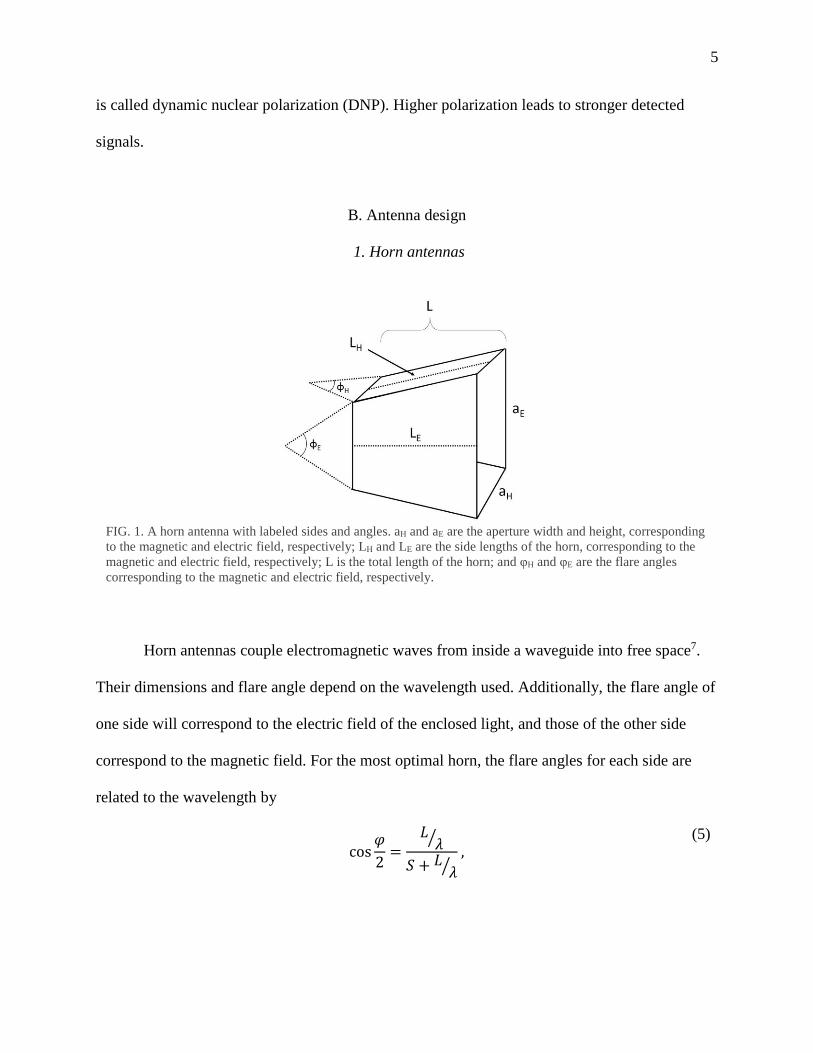
FIG. 1. A horn antenna with labeled sides and angles. aH and aE are the aperture width and height, corresponding
to the magnetic and electric field, respectively; LH and LE are the side lengths of the horn, corresponding to the
magnetic and electric field, respectively; L is the total length of the horn; and φH and φE are the flare angles
corresponding to the magnetic and electric field, respectively.
6
where φ is the flare angle of either the electric or magnetic field (φ H or φ E, respectively), L is the
total length of the horn, λ is the wavelength, SH=0.4 and SE=0.25 (Ref. 8). The dimensions of the
aperture are related to the wavelength by
𝑎𝐸 = √2𝜆𝐿𝐸 ,
𝑎𝐻 = √3𝜆𝐿𝐻 , (6)
where LH and LE are the lengths of the flared sides9 and can be calculated using the angle and
total length calculated from equation (5). A labeled horn is shown in Fig. 1. The aperture width
should be greater than the wavelength of the enclosed light. The aperture height is arbitrary, but
it must be less than the aperture width. The horn serves to guide waves into free space with as
little distortion as possible. If the surroundings of the wave change too rapidly, there will be
distortion around the edges. For this reason, the horn must expand gradually at a flare angle of
less than 40 degrees.
2. Dipole antennas
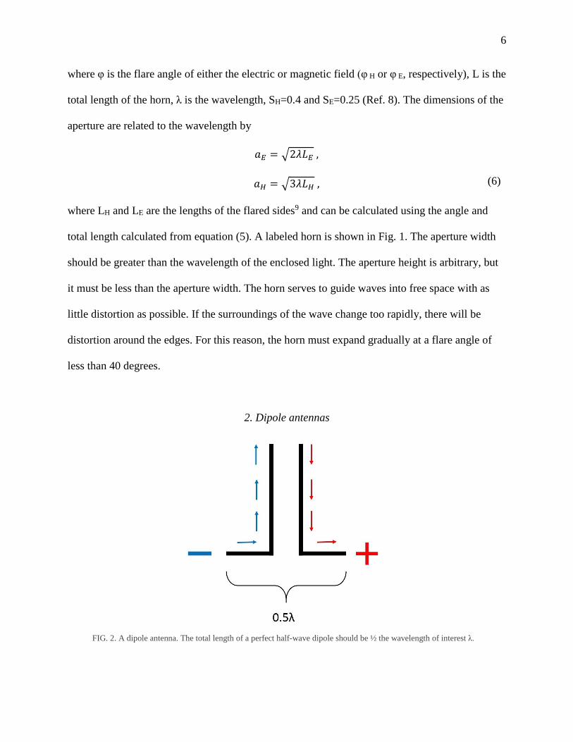
FIG. 2. A dipole antenna. The total length of a perfect half-wave dipole should be ½ the wavelength of interest λ.

7
Dipole antennas are formed from two conductors parallel to each other on the same axis
as shown in Fig. 2. Their length will depend on the desired wavelength. For a perfect half-wave
dipole, the total length should be half of the desired wavelength10. A half-wave dipole produces a
standing wave which radiates isotropically perpendicular to the axis of the two conductors.
III. METHODS & MATERIALS
To select the best antenna design, I used CST Microwave Studio 2017 to digitally build
and simulate antennas. 3D CAD models of an antenna are made by generating elemental shapes
and defining material parameters. These models are shown in Fig. 3.
The time-domain solver solves Maxwell’s equations inside the antenna. It approximates
the expectation values throughout the antenna via Finite Element Modelling. The elements are
generated from a mesh – a grid with cell sizes determined by the user. An example of this mesh
can be seen in Fig. 4.
(a) (b)
FIG. 3. (a) 3D model of a horn antenna. (b) 3D model of a dipole antenna.

8
The simulations provide important information about the antenna, such as the
propagation of the electric and magnetic fields and the scattering parameters (S-parameters).
Scattering parameters give the relationships between the incident, reflected, and transmitted
signals in a system. For systems with multiple ports, the S-parameters are represented by a multi-
dimensional square matrix. Our system is a one-port system, so the S-parameter is a one-
dimensional square matrix, and represents the ratio of reflected to incident signal. Using the
time-domain solver, I simulated data for several iterations of horn and dipole antennas. In many
cases it was necessary to sweep various parameters to find the optimum dimensions of the
antenna for our specifications.
Once the simulations were complete, we constructed a dipole antenna and the assembly
required to operate it. The antenna itself is made from an Anritsu K118 semi-rigid coaxial cable,
suitable from 0-46 GHz, terminated at one end by a half-wave dipole antenna. It is placed inside
a homebuilt probe. The microwave source is a MicroLambda YIG oscillator being run between 0
FIG. 4. Mesh view of the dipole antenna.

9
V and -2 V to achieve the resonance frequency needed (16.5-18.5 GHz). The YIG is coupled into
a DBS Microwave Doubling Amplifier, which both doubles the frequency and amplifies the
microwave field. This produces microwaves with a frequency of 18.5 GHz, with a wavelength of
approximately 16 mm, which are coupled into the coaxial cable via an Anritsu K-connector. The
RF pulse is generated by a Tecmag Scout Spectrometer and amplified by an American
Microwave Technologies Linear Amplifier. We used a 3 T Oxford wide bore superconducting
magnet. The probe is operated inside an Oxford Continuous Flow Cryostat (CF1200) at 3.8 K.
Temperature was monitored at the sample space with a Cernox temperature sensor.
IV. RESULTS & DISCUSSION
The S-parameters obtained from optimizing the horn aperture width are shown in Fig. 5.
Lower scattering occurs for lower values on the graph. As shown in the figure, the least
FIG. 5. A graph of S-parameters versus frequency, generated from varying the aperture width of the horn from 18 to 48 mm.
10
scattering occurs at a horn width of ~32 mm at 18.5 GHz. This size is impractically large
compared to the space available in our probe. Furthermore, the aperture was so much larger than
our sample size that the radiated power would have been weak and inefficient.
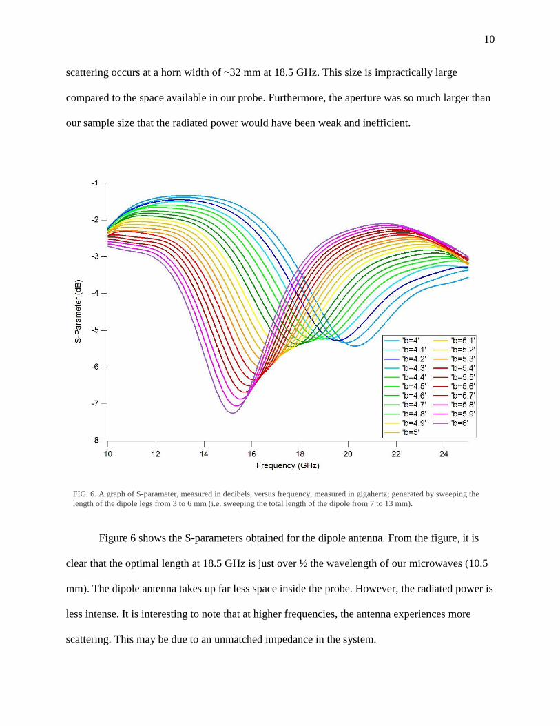
Figure 6 shows the S-parameters obtained for the dipole antenna. From the figure, it is
clear that the optimal length at 18.5 GHz is just over ½ the wavelength of our microwaves (10.5
mm). The dipole antenna takes up far less space inside the probe. However, the radiated power is
less intense. It is interesting to note that at higher frequencies, the antenna experiences more
scattering. This may be due to an unmatched impedance in the system.
FIG. 6. A graph of S-parameter, measured in decibels, versus frequency, measured in gigahertz; generated by sweeping the
length of the dipole legs from 3 to 6 mm (i.e. sweeping the total length of the dipole from 7 to 13 mm).

11
Looking at radiated power, the horn antenna would be ideal because it produces higher
power microwaves. However, the beam width of those microwaves is much larger than the
sample, so a lot of that power would be wasted. Also, the horn, with its width of 32 mm, is
simply too big to fit inside our probe. The dipole antenna, while producing less intense
microwaves, can fit easily inside our probe, with a width of only 10.5 mm. Therefore, we
determined that the dipole antenna is the best option for our probe.
Figure 7 shows the dipole antenna installed in the probe. One arm is made directly from
the center conductor of the coaxial cable, and the other is made from the same material and
soldered to the outer conductor. We implemented what is called a “common-mode choke” by
grounding the antenna (i.e. attaching the arm to the outer conductor) several wavelengths away
from the antenna arms. Through preliminary testing, we have determined that the antenna is
successfully producing microwaves.
FIG. 7. Microwave antenna installed in the probe, indicated by a black arrow. The copper coil encloses the sample just to the
right of the antenna.

12
We acquired DNP NMR with a 30 nm quantum well affixed to a silicon substrate (sample
EA124). The previously undetected thin film gave ample signal when irradiated with
microwaves and laser light to promote carriers for DNP. As is seen in Fig. 8, we have sizeable
enhancement.
V. CONCLUSION
CST Microwave Studio was employed to simulate horn and half-wave dipole antennas at 18.5
GHz. From the simulated antennas, we determined that a half-wave dipole antenna was best
suited for our experimental setup. Once we determined this, we constructed the dipole antenna
FIG. 8. Preliminary DNP NMR data. The bottom trace shows the thermal signal, i.e. the signal obtained at thermal
equilibrium with no microwave radiation. The top trace shows the enhancement achieved by irradiating with microwaves.
This signal was acquired at 3 T, 3.8 K, with 200 mW laser power, and with microwaves swept from 17.3-18.5 GHz at a rate
of 0.01 GHz min-1.

13
based on the simulation data and attempted to perform DNP-NMR using it. With further testing,
we can fine-tune our antenna so that it works optimally in our probe. Once we fabricated the
dipole antenna, we were able to observe signal enhancement in a sample of EA124. Further work
will look to optimize the signal, including frequency sweep rate, frequency range, and laser
intensity.
ACKNOWLEDGEMENTS
I would like to thank the University of Florida for hosting this REU program, and Dr. Selman
Hershfield for coordinating it. I would also like to thank Dr. Russ Bowers, John Tokarski III, and
the Bowers Research Group for all their help this summer. This project was funded by NSF
DMR-1461019.

14
REFERENCES
1M. Rosay et al., Phys. Chem. Chem. Phys. 12, 22 (2010).
2M. Rosay et al., J. Am. Chem. Soc. 123, 5 (2001).
3James Keeler, Understanding NMR Spectroscopy (John Wiley & Sons, West Sussex, 2005), p.
14-47.
4T. V. Can et al., J. Chem. Phys. 141, 6 (2014).
5Daniel Loss and David P. DiVincenzo, Phys. Rev. A 57, 1 (1998).
6Daniel V. Schroeder, An Introduction to Thermal Physics (Addison Wesley Longman, San
Francisco, 2000), p. 223.
7Andrew Alford, Very High-Frequency Techniques, edited by Herbert J. Reich et al. (Boston
Technical Publishers, inc., Cambridge, 1965), p. 1-25; Jessie A. Nelson, David Lazarus, John W.
Christensen, and Robert R. Buss, ibid., p. 138-170.
8William Sinnema, Electronic Transmission Technology (Prentice Hall, Upper Saddle River,
1988), p. 296.
9Tasuku Teshirogi, Modern Millimeter-wave Technologies (IOS Press, Clifton, 2000), p. 87.
10Clayton R. Paul, Introduction to Electromagnetic Compatibility (John Wiley & Sons, West
Sussex, 2006), p. 433