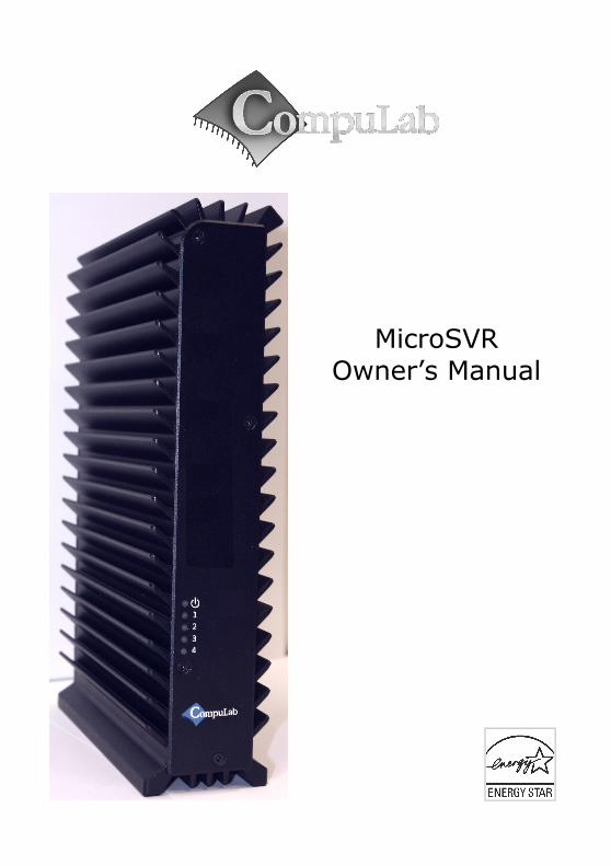
MicroSVR Owner’s Manual
10
MicroSVR Owner’s Manual
Transcript of MicroSVR Owner’s Manual
MicroSVROwner’s Manual
MicroSVR Owner’s Manual27. Sep. 2012
Introduction
Package contents
Hardware specifications
MicroSVR features
Quick start guide
Connecting MicroSVR
Booting Linux
Booting Windows 7
Maintenance
Opening service door
Service bay
BIOS Setup Utility
Warranty and RMA
Warranty
RMA
Tips for saving power
General
In Operating System
For more information and to obtain the latest revision of this document, please visit
www. compulab.co.il
2
Introduction
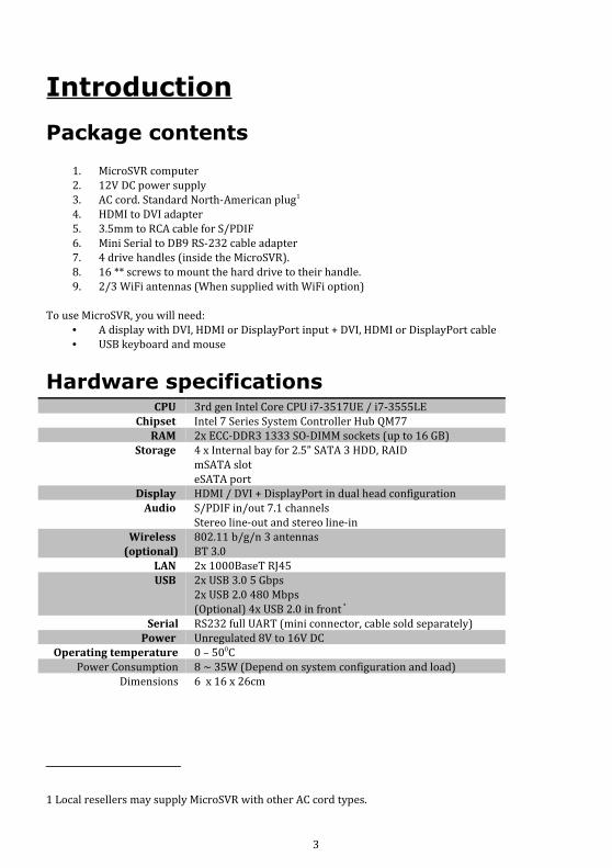
Package contents
1. MicroSVR computer2. 12V DC power supply3. AC cord. Standard North-American plug1
4. HDMI to DVI adapter5. 3.5mm to RCA cable for S/PDIF6. Mini Serial to DB9 RS-232 cable adapter7. 4 drive handles (inside the MicroSVR).8. 16 ** screws to mount the hard drive to their handle.9. 2/3 WiFi antennas (When supplied with WiFi option)
To use MicroSVR, you will need:• A display with DVI, HDMI or DisplayPort input + DVI, HDMI or DisplayPort cable• USB keyboard and mouse
Hardware specificationsCPU 3rd gen Intel Core CPU i7-3517UE / i7-3555LE
Chipset Intel 7 Series System Controller Hub QM77RAM 2x ECC-DDR3 1333 SO-DIMM sockets (up to 16 GB)
Storage 4 x Internal bay for 2.5” SATA 3 HDD, RAIDmSATA sloteSATA port
Display HDMI / DVI + DisplayPort in dual head configurationAudio S/PDIF in/out 7.1 channels
Stereo line-out and stereo line-inWireless
(optional)802.11 b/g/n 3 antennasBT 3.0
LAN 2x 1000BaseT RJ45USB 2x USB 3.0 5 Gbps
2x USB 2.0 480 Mbps(Optional) 4x USB 2.0 in front *
Serial RS232 full UART (mini connector, cable sold separately)Power Unregulated 8V to 16V DC
Operating temperature 0 – 500CPower Consumption 8 ~ 35W (Depend on system configuration and load)
Dimensions 6 x 16 x 26cm
1 Local resellers may supply MicroSVR with other AC cord types.
3

MicroSVR features
Front panelThe front panel includes 5 LED's:
• Power, a dual function Green/Yellow led.◦ Green after the MicroSVR was turned on and initial CPU/Chipset
initialization was successfully passed.◦ Yellow when any hard disk is accessed (internal or external – eSATA).
• Drive Activity 1..4 . The Drive Activity LED's work according to SFF8489 IBPI ( International Blinking Pattern Interpretation). ◦ At power-up, the LED controller will lit all Drive Activity LED's as part of
it's wake-up self test.
Additional features of the front panel depend on the specific FACE Module used and are documented separately.
4
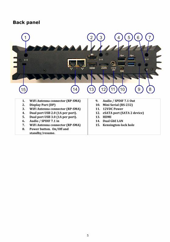
Back panel
5
1 2 3 4 5 6 7
15 14 1213 11 10 9 8
1. WiFi Antenna connector (RP-SMA)2. Display Port (DP)3. WiFi Antenna connector (RP-SMA)4. Dual port USB 2.0 (1A per port).5. Dual port USB 3.0 (1A per port).6. Audio / SPDIF 7.1 in7. WiFi Antenna connector (RP-SMA)8. Power button. On/Off and
standby/resume.
9. Audio / SPDIF 7.1 Out10. Mini Serial (RS-232)11. 12VDC Power12. eSATA port (SATA 2 device)13. HDMI14. Dual GbE LAN15. Kensington-lock hole
Quick start guide
Connecting the MicroSVR
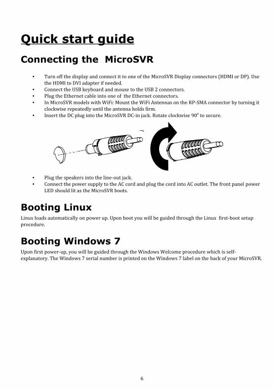
• Turn off the display and connect it to one of the MicroSVR Display connectors (HDMI or DP). Use the HDMI to DVI adapter if needed.
• Connect the USB keyboard and mouse to the USB 2 connectors.• Plug the Ethernet cable into one of the Ethernet connectors.• In MicroSVR models with WiFi: Mount the WiFi Antennas on the RP-SMA connector by turning it
clockwise repeatedly until the antenna holds firm.• Insert the DC plug into the MicroSVR DC-in jack. Rotate clockwise 900 to secure.
• Plug the speakers into the line-out jack.• Connect the power supply to the AC cord and plug the cord into AC outlet. The front panel power
LED should lit as the MicroSVR boots.
Booting Linux Linux loads automatically on power up. Upon boot you will be guided through the Linux first-boot setup procedure.
Booting Windows 7 Upon first power-up, you will be guided through the Windows Welcome procedure which is self-explanatory. The Windows 7 serial number is printed on the Windows 7 label on the back of your MicroSVR.
6
MaintenanceThe MicroSVR requires no maintenance. You should not take the MicroSVR apart other than opening the front panel to install/remove disks. Taking the MicroSVR apart will void its warranty.The following operations can be conducted by the user:
Installing the Hard drives
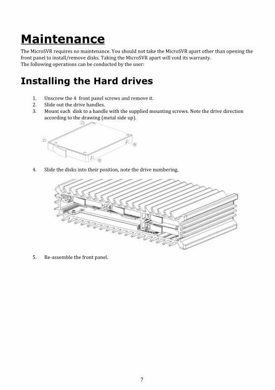
1. Unscrew the 4 front panel screws and remove it.2. Slide out the drive handles.3. Mount each disk to a handle with the supplied mounting screws. Note the drive direction
according to the drawing (metal side up).
4. Slide the disks into their position, note the drive numbering.
5. Re-assemble the front panel.
7
RAID configuration utility The RAID option must be enabled in BIOS before the system can load the Intel® RAID Option ROM code.
1. During boot, enter the BIOS setup by pressing F2.2. Go to Advanced > Drive Configuration.3. Set Configure SATA As to RAID.4. Press F10 to save setting and exit the BIOS Setup program.
At boot time the RAID configuration utility can be invoked by pressing <CTRL-I> (Control I) key combination.The Raid configuration utility is made by Intel. It it documented in: “Intel® Rapid Storage Technology (Intel® RST) user guide” which can be downloaded from the intel web site.
BIOS Setup UtilityEntering BIOS Setup UtilityTurn off the MicroSVR.Turn on while holding down the F2 key.Additional BIOS information or updates can be found in: http://fit-pc.com/wiki/index.php/IntensePC:_BIOS_Documentation
Warranty and RMA
Warranty• CompuLab guarantees products against defects in workmanship and material for a period of 24
months from the date of shipment.• Your sole remedy and CompuLab’s sole liability shall be for CompuLab, at its sole discretion, to
either repair or replace the defective product at no charge.• This warranty is void if the product has been altered or damaged by accident, misuse or abuse.
RMAKeep the original package for shipping in case of hardware failure.In case of HW failure of an MicroSVR under warranty, please contact the seller of that MicroSVR.Please provide the following required information:
• MicroSVR serial number• Name of purchaser• Address• Problem description
If the MicroSVR was purchased directly from CompuLab, please email [email protected].
8

Tips for saving power
General• Working without a connected display automatically disables the graphics controller – saving
power.• Disconnect external USB devices when not in use.
In Operating SystemUse power scheme as follows
• Turn of monitor after several minutes not in use• Turn off hard disk after several minutes not in use• System standby after an hour not in use
This PC is ENERGY STAR® compliant. The power management settings enabled by default on this PC have been selected for compliance with the current ENERGY STAR requirements. For optimal energy savings, ENERGY STAR recommends that sleep mode is entered within 30 minutes of user inactivity, and the display is turned off within 15 minutes of user inactivity.
The default power management settings on this PC are:
• Go into sleep mode within 30 minutes of inactivity.• Turn off the display within 15 minutes of inactivity.
Move the mouse or press any key on the keyboard to wake this computer from Sleep mode.
To learn more about effective power management for computers and the financial savings potential, energy savings potential, and environmental benefits, please visit www.energystar.gov/powermanagement.
To learn more about how your organization can benefit by reducing the energy consumption of their IT equipment, please visit the Low Carbon IT Campaign website.
9

10