A comparative study of copper thin films deposited using ...

i
MICROSTRUCTURAL ANALYSIS OF COPPER THIN FILMS FOR
CHARACTERIZATION OF STRESS-INDUCED VOIDING MECHANISMS
by
Ryan Camacho
Submitted to the Department of Physics and Astronomy in partial fulfillment
of graduation requirements for the degree of
Bachelor of Science
Brigham Young University
May 2003
Advisor: David Allred Thesis Coordinator: Justin Peatross
Signature: _________________________ Signature: _________________________
Department Chair: R. Steven Turley
Signature: _________________________

ii
Abstract
The amount of twin formation of electroplated and thermally treated copper thin
films was evaluated by electron back-scattering diffraction (EBSD) analysis. The result
establishes the importance of twin formation in the analysis of stress-induced voiding,
and indicates that with the inclusion of a copper alloy co-element, twin formation was
significantly reduced relative to pure-copper. Furthermore, the thermal stress hysteresis
curve of the Cu-Sn(0.01wt%) thin film indicated a higher flow stress than that of pure-
copper. These indications are consistent with the theory of suppressed grain deformation
and reduced grain boundary elimination by particle pinning of grain boundaries during
microstructure evolution of electroplated copper thin film. With the growth of the grains
inhibited, both boundary filling and vacancy generation issues are suppressed, and the
number of twin boundaries as void nucleation sites are reduced. Thus, the copper alloy
film is believed to be more resistant to stress-induced voiding.

iii
CONTENTS
1. Introduction 1 1.1 Overview 1 1.2 Background 2 1.2.1 Copper Plating 2 1.2.2 Damascene Process 3 1.2.3 Stress-Induced Voiding (SIV) 4
2. Experimental Setup 7 2.1 Electroplating System and Process Characteristics 7 2.2 Experimental Setup 7 2.2.1 300 mm Center to Edge Annealing Experiment 7 2.2.2 200 mm Cu and CuP Anode Experiment 8 2.2.3 200 mm CuSn experiment 8
3. Results 10 3.1 Experiment 1: Comparison of Center to Edge 10 3.2 Experiment 2: Comparison of using a Copper anode 14 and using a Copper-Phosphorus Anode 3.3 Experiment 3: CuSn Microsructure Analysis 16 3.3.1 Film Composition Analysis 16 3.3.2 Film Microstructural Analysis 18 3.4 Conclusions 21

1
CHAPTER I. INTRODUCTION
1.1 Overview
In the past five years, copper has replaced aluminum as the interconnect metal of
choice in microchip fabrication. The main advantage of copper is its low electrical
resistivity and high resistance to electro-migration and stress-migration, (in comparison
with aluminum.) Lower resistance means that smaller and more tightly packed metal
lines can carry the same amount of current. This leads to fewer levels of metal, faster
speed, and lower production costs.
The chief drawback to copper is its high diffusivity. To prevent copper from
diffusing into transistors, it must be encapsulated in a barrier film, usually a derivative of
tantalum or titanium. In addition, to reduce the extra parasitic capacitance in denser
circuits, dielectrics with lower dielectric constants must be used. The spin-on-coat
process of low-k dielectric material requires furnace annealing to cure the film.
During this thermal processing, however, the copper is mechanically confined in the
bulk layer by the barrier metal and in the vias/trenches by sidewalls. As the copper and
dielectric materials are heated and cooled, their different thermal coefficients of
expansion lead to a mismatch in the residual stress of the copper in the bulk layer and
trenches. The mismatch leads to stress migration and eventually stress induced voiding
(SIV) in the copper during chip operation. Voids increase the resistance and lead to chip
failure. Obviously, this causes a severe problem in chip reliability.
The current project investigates the stress characteristics of bulk copper films in an
attempt to characterize the origins of stress voiding. This project also demonstrates that
Formatted: Widow/Orphan control

2
SIV may be suppressed by replacing copper with a copper alloy. I investigated tin as a
first likely candidate. The alloy reduces the overall change in grain size during thermal
cycling, thereby suppressing the effects of mechanical confinement. My contribution to
the project was to design the relevant experiments, perform the metrology, and interpret
the results.
1.2 Background
1.2.1 Copper Plating
Electrochemical plating (ECP) is presently the most popular method used for Cu
deposition in semiconductor fabrication processes. The electrodeposition of copper (or
any other metal) is achieved by placing a piece of conducting material into a solution
(electrolyte) containing copper ions. The conductor is placed in electrical contact with a
power supply, and current passes through both the conductor and the solution. This
induces a reaction between the copper ions and the conducting surface to form a metal on
the surface of the conductor. In the present experiments, the conducting surface used is a
silicon wafer containing a thin layer of copper deposited by sputtering. As copper is
plated on the cathode (negative electrode), copper goes into the solution at the anode
(positive electrode) as copper(II) ions, maintaining a constant concentration of copper(II)
ions in the electrolytic solution. Figure 1 shows a diagram of a typical plating setup with
the relevant chemical reactions shown next to the cathode and anode.

3
Figure 1. Schematic of copper electroplating chamber and process.
1.2.2 Damascene Process
Microchips fabricated using copper interconnects are made using the damascene
process. In the damascene process, a dielectric layer is first deposited and then etched
using photolithographic techniques. Etching the dielectric layer leaves a pattern of
trenches into which copper is then deposited by plating. Electroplating, of course,
deposits a copper film covering both etched and non-etched areas; so after plating, the
whole surface must be polished down until the only copper remaining resides in the
trenches. The resulting copper lines (in the trenches) form the circuit through which
current will pass in a fully functioning microchip. These trenches are where the thermal

4
expansion and contraction of copper is most critical, due to the increased mechanical
confinement.
Until copper replaced aluminum as an interconnect metal, aluminum was first
deposited and then space was etched for the dielectric, the reverse of the damascene
process. Even though the aluminum process in many respects is less technically
challenging and certainly more thoroughly studied, it cannot be used for copper. This is
because copper is not easily etched. Since the more difficult damascene process must be
used for copper plating, the process must be much more carefully controlled in order to
properly fill trenches and prevent excessive stress migration during annealing.
1.2.3 Stress Induced Voiding (SIV)
Stress migration failure was not originally expected for Cu, since it normally has
lower diffusivity than aluminum. However, voiding in passivated (encapsulated) copper
films was observed in the very first attempts to fabricate copper interconnect structures.
[1] In films that are mechanically confined, as in the damascene process,
thermomechanical stresses are induced during cooling after thermal annealing. After
cooling, the film is in a state of hydrostatic tension. The resulting stress is the driving
force behind both void nucleation and subsequent morphological evolution. [2]
The phenomenon of stress-induced voiding is generally understood as a result of stress
mismatch in materials [3] and structures [4] in copper interconnects. Copper is
mechanically confined in the trenches and via holes by sidewall barrier metal and
encapsulation dielectric film. This results in stress mismatch after thermal cycling, which
leads to stress-induced voiding during the subsequent process steps and chip operation.
5
Microstructural analysis of copper thin film is increasingly important for
understanding stress-induced voiding kinetics. Microstructure dependence of stress-
induced voiding in copper thin films mainly comes from its effects on vacancy diffusion
and void nucleation [5-8]. The grain boundaries themselves are full of vacancies, and the
free volume released by grain growth as the result of grain boundary elimination creates
sizeable voids [5]. Also, the grain boundary is one of the fast diffusion paths in copper
interconnect, and the diffusivities are influenced by the misorientation angle of grain
boundaries [6, 7]. Moreover, twin boundaries have been found to be nucleation sites for
stress-induced voiding due to thermal stress concentration at their interfaces [8]. So,
copper films with larger grains (fewer grain boundaries) that also maintain strong
crystallographic orientation and minimum twin formation are preferred for stress-induced
voiding resistance in copper interconnects.
Many methods have been suggested to suppress stress voiding in copper interconnects.
Most of these involve either altering the geometry of the line/via structure, changing the
dielectric materials to improve passivation, or optimizing the thermal cycling process in
an attempt to make it more robust.[5] In addition, it has been theorized that the inclusion
of a small amount of a second metal in copper thin films during electroplating and its
subsequent segregation at grain boundaries by thermal treatment suppresses the copper
grain boundary diffusivity. Also, in addition to possibly creating interstitial defects in the
copper crystallite lattice, the alloyed co-element may fill the vacancies inherent at grain
boundaries. The co-element thereby affects both the grain size distribution and thermal-
mechanical properties (i.e. flow stress) of the copper thin films by particle pinning of
grain boundaries. [9] In the present study, a Cu-Sn(0.01wt%) thin film was subjected to
Deleted: ,7

6
grain size, grain orientation, and twin fraction analysis by electron backscattering
diffraction (EBSD) [10] and compared to those of pure-copper thin films to evaluate the
potential advantage for stress-induced voiding.

7
Chapter II. EXPERIMENTAL SETUP
2.1 Process Characteristics
800 nm copper thin films were deposited by electroplating over PVD copper seed (125
nm) with PVD Ta (25 nm)/Thermal-SiO2 (500 nm) underlayers on Si-substrate using a
process after that of Padhi et al. [11]. In the copper alloy experiment, tin-sulfate along
with anti-oxidation stabilizer was dosed into the electroplating bath to incorporate tin into
copper thin film while electroplating. The samples were annealed at various annealing
conditions for 1min in a forming gas ambient immediately following the deposition.
Forming gas is dilute H2 in an inert gas. Tin incorporation in the copper thin film was
confirmed by secondary ion mass spectroscopy (SIMS) analysis. Copper lattice spacing
calculation, during in-plane strain analysis by x-ray diffraction (XRD), was also
employed to complement the SIMS analysis result. EBSD was applied for grain size and
grain orientation analysis, and twin fraction was also acquired from the EBSD grain-
orientation images.
2.2 Experimental Setup
2.2.1 300 mm Center to Edge Annealing Experiment
Three experiments were performed to characterize the possible causes of stress
migration failure in copper interconnects. The first was an analysis of the differences in
the center and edge of 300-mm copper-plated wafers. It had been previously observed
that the highest rate of stress migration failure results from chips fabricated on the edge
of 300-mm wafers, while chips fabricated in the center show a dramatic reduction in
Deleted: seed(

8
failures due to stress induced voiding. Extensive microstructure analysis was therefore
performed after the samples were annealed in various ways. Table 1 shows the matrix of
annealing conditions used in this experiment. Note that the cool-down rate is changed by
varying the distance between the wafer and the cooling plate, which is at a constant
temperature.
Low Mid High Anneal Temp. 150 C 180 C 210 C Anneal Time 30 sec. 60 sec. 90 sec.
Cooling Rate 3850 steps
30 sec
3800 steps 30 sec
3500 steps 60 sec
Table 1. Matrix of annealing conditions used in 300 mm center to edge experiment.
2.2.2 200 mm Cu and CuP Anode Experiment
In the second experiment, the microstructural properties of 200-mm wafers were
analyzed with two different metal compositions used as anodes during plating. There are
two anodes currently used in industry for plating 200-mm copper wafers. The first and
most common is a high purity uniform copper wafer. The second, less commonly used
anode is composed of copper doped with phosphorus. The phosphorus is included to
prevent adverse competing reactions at the anode. Applied Materials uses pure copper
anodes, but their chief competitor uses copper phosphorus and seems to have a greater
resistance to stress migration.

9
2.2.3 200 mm CuSn experiment
The third experiment was similar to the anode experiment described in the previous
section, except that a chemical difference is introduced in the electrolyte bath rather than
changing the anode. I chose tin as the dopant in this experiment since I thought that it
may be co-deposited with the copper and integrate into the microstructure of the plated
copper film. (This turned out not to be the case because of a steep deposition potential
curve due to underpotential effects. The tin was merely flowed in.) The microstructure of
this film was then compared to the standard film.
Deleted: than changing

10
Chapter III. RESULTS
3.1 Experiment 1: Comparison of Center to Edge
Figure 2 shows that the wafer stress is not significantly different in the center than at
the edge after plating and annealing. This suggests that local stress in the copper may not
be the reason for stress migration failure. Typical tensile stress measurements for the
ECP films at both center and edge of the wafer were between 85 and 90 GPa.
Figure 2. Stress difference between center of edge of 300 copper plated wafer and sputtered copper barrier/seed film. Table 2 shows the measured crystallite size from XRD in the <111> orientation at both
the center and edge of the wafer after annealing. While the barrier/copper seed layer
shows uniform crystallite size, the plated copper shows a significant increase in
crystallite size near the wafer center. Table 3 shows the strength of the <111> preferred
orientation. While the crystallites at the edge with <111> orientation show stronger
texture ( i.e. narrower peaks) there are relatively much fewer of them. This is indicated
by the high percentage of random and other orientations at the wafer edge.
0.737200.737400.737600.737800.738000.738200.738400.738600.738800.73900
0 0.1 0.2 0.3 0.4 0.5 0.6 0.7 0.8 0.9 1sin2psi
d-sp
acin
g
ECPCenterECPEdgeB/SCenterB/SEdge

11
Table 2. Crystallite size of copper ECP film after annealing as measured by XRD.
Table 3. Strength of <111> crystallite orientation at wafer center and wafer edge measured by XRD. The table indicates the angular spread in the measured diffraction peak containing 10, 50, 63, and 90 percent of the peak. The narrower the peak, the stronger the texture.
Figure 3 shows EBSD generated pole figures that indicate that the wafer center has
much stronger <111> texture than the wafer edge after annealing, confirming the XRD
analysis shown above.
Wafer Location FWHM Corrected FWHM*
Crystallite Size (Å)
Center 0.221 0.092 473Edge 0.222 0.093 476
Center 0.172 0.043 942Edge 0.158 0.029 751
B/S
ECP
Wafer Location 10% (degrees)*
50% (degrees)*
63% (degrees)*
90% (degrees)*
% Random Other Orientations
Center 0.46 2.6 3.4 6.6 <5% NoneEdge 0.40 2.3 3.0 6.0 <5% None
Center 0.71 3.6 4.8 8.8 37% (511) and othersEdge 0.42 2.4 3.2 6.0 60% (511) and others
B/S
ECP

12
(a) (b) Figure 3. Representative EBSD pole figures of 300 mm wafers after annealing at wafer center (a) and edge (b).
The grain size distribution was also found to vary among different annealing
conditions. Notably, when the same data are graphed excluding twin grain boundaries,
the average grain size at the wafer edge is significantly higher than the average grain size
at the center.

13
Figure 4 shows the resulting grain size distribution from the matrix of annealing
conditions shown in table 1, as measured by EBSD.
Figure 4. Grain size distribution different among different post ECP anneal conditions shown in table 1.
These data reveal that with the same thermal treatment, the lattice structure at the
wafer edge is much more likely to deform to a more negative free energy, twin-boundary
state. This suggests that the lattice was in a higher energy state upon deposition and
required less energy input during thermal cycling to induce plastic deformations. As
indicated by the grain texture measurements, this is probably due to weaker texture and
hence lower binding energies. As more heat is applied, the observed disparity in twin
formation from center to edge increases. Excessive grain growth and the corresponding
weaker texture are likely the cause of stress migration failure at the wafer edge.
0
0.02
0.04
0.06
0.08
0.1
0.12
0.1 1.0 10.0Grain Size Distribution (microns)
Are
a Fr
actio
n
Low(Center)
Low(Edge)
Mid(Center)
Mid(Edge)
High(Center)
High(Edge)
0
0.02
0.04
0.06
0.08
0.1
0.12
0.14
0.16
0.18
0.2
0.1 1.0 10.0 100.0Grain Size Distribution (microns)
Are
a Fr
actio
n
Low(Center)
Low(Edge)
Mid(Center)
Mid(Edge)
High(Center)
High(Edge)
14
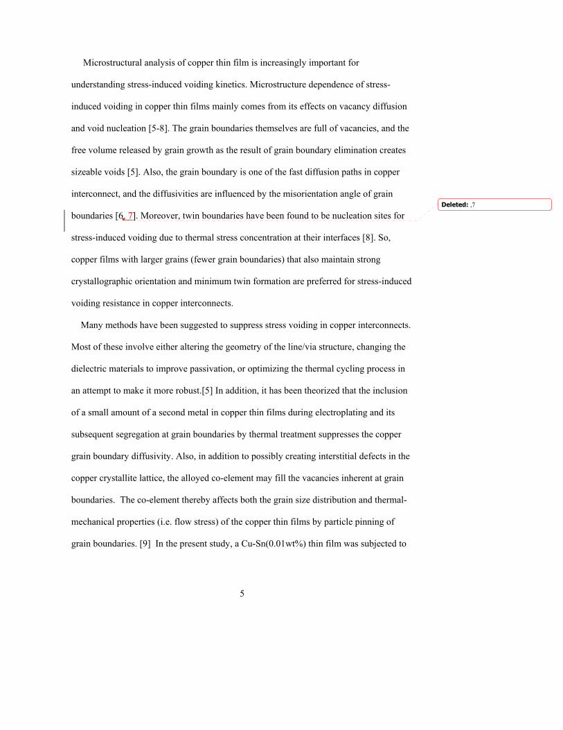
3.2 Experiment 2: Comparison of Copper anode with the Copper-
Phosphorus Anode on Microstructure of Copper Films
Figure 5 shows lattice strain and spacing measurements for wafers plated using a
copper anode system as opposed to a copper-phosphorus anode. Although the in-plane
strain (slope) in on the same order of magnitude (about 100GPa), the copper on the
wafers deposited using with the copper-phosphorus anode show different lattice spacing
(intercept) at the wafer edge than those produced with the customary pure copper anode.
Table 4. Local Stress of Cu and
Figure 5. Lattice spacing of Cu and CuP CuP ECP films
as measured by XRD
Secondary ion mass spectroscopy (Figure 6) revealed slightly higher amounts of
phosphorus in the copper films plated with the copper-phosphorus anode, suggesting that
the increased lattice parameter near the wafer edge shown in figure 5 may be due to
increased amounts of phosphorus. Recall that the center vs. edge texture data from
experiment 1 reveal weak texture at the wafer edge, implying excess volume due to grain
boundary misalignment. This suggests that the phosphorus may be accumulating at the
grain boundaries. X-ray diffraction further revealed the average crystallite size in the
copper plated with a phosphorus anode to be roughly half as large as the crystallites
0.73720
0.73740
0.73760
0.73780
0.73800
0.73820
0.73840
0.73860
0.73880
0.73900
0 0.1 0.2 0.3 0.4 0.5 0.6 0.7 0.8 0.9 1sin2psi
d-sp
acin
g
Cu MidCenter
Cu MidEdge
CuHighCenterCu HiEdge
CuPMidCenterCuPMidEdge
Wafer Location Stress (Gpa)
Center 91.2Edge 108.1
Center 111.47Edge 95.71
Center 95.70Edge 102.46
CuP
Cu High
Cu Mid

15
plated with the pure copper anode. (450 vs. 900 angstroms). This was also found to be
consistent with surface roughness and hardness analysis, which showed that the
phosphorus wafers had both harder and rougher surfaces. This suggests that the
phosphorus precipitates to the grain boundaries to fill excess volume and raises the
critical free energy necessary for both plastic and elastic deformation.
(a) (b) Figure 6. Depth profile of impurity concentrations in the electroplated copper thin films by SIMS analysis: (a) Cu and (b) CuP
X-ray diffraction texture analysis (Table 5) show that the pure copper wafers have
strong <111> orientation, while the phosphorus doped wafers have only moderate <111>
orientation. In addition, the pure copper wafers show significant <511> twinning, and
additional “other” orientation. Hence, even though, the phosphorus doped films have
weaker texture, they show much lower amounts of <511> twinning and random
components, suggesting that the grain boundaries have been effectively pinned during
thermal annealing. Electron backscattering pole figures (Figure 7) also reveal the strong
<111> texture in both films.
1E+14
1E+15
1E+16
1E+17
1E+18
1E+19
1E+20
1E+21
1E+22
0 0.2 0.4 0.6 0.8 1
DEPTH (microns)
CO
NC
EN
TRA
TIO
N (a
tom
s/cc
)
1E+00
1E+01
1E+02
1E+03
1E+04
1E+05
1E+06
1E+07
SE
CO
ND
AR
Y IO
N C
OU
NTS
Cu(counts)->
Ta(counts)->
C
O
S
P
31 Jan 20 02 Cs FILE: E4878d4 1
Wafer # 4
valid in Cu only
1E+14
1E+15
1E+16
1E+17
1E+18
1E+19
1E+20
1E+21
1E+22
0 0.2 0.4 0.6 0.8 1
DEPTH (microns)
CO
NC
EN
TRA
TIO
N (a
tom
s/cc
)
1E+00
1E+01
1E+02
1E+03
1E+04
1E+05
1E+06
1E+07
SE
CO
ND
AR
Y IO
N C
OU
NTS
Cu(counts)->
Ta(counts)->
O
S
P
C
31 Jan 2002 Cs FILE: E4878d31
Wafer # 3
valid in Cu only
CuP Cu

16
Table 5. Strength of Cu and CuP ECP films <111> crystallite orientation at wafer center and wafer edge measured by XRD.
Figure 7. EBSD generated pole figures for Cu and CuP ECP films.
3.3 Experiment 3: CuSn Microsructure Analysis
3.3.1 Film Composition Analysis
SIMS analysis indicated uniform distribution of tin incorporated across the bulk of the
electroplated copper thin film without significantly affecting the other impurity
concentrations, i.e. oxygen and carbon, as shown in Figure 8.
Wafer Location 10% (degrees)*
50% (degrees)*
63% (degrees)*
90% (degrees)*
% Random Other Orientations
Center 0.16 0.94 1.3 3.3 13 (511) traceEdge 0.21 1.2 1.7 3.8 13 (511) trace
Center 0.11 0.75 1.1 2.4 20 (511) and othersEdge 0.13 0.62 0.88 2.1 23 (511) and others
CuP
Cu
Cu CuP

17
Figure 8. Depth profile of impurity concentrations in the electroplated copper thin film by SIMS analysis: (a) Cu-Sn and (b) pure-copper. Tin concentration is uniformly distributed across the bulk of the copper film, and the increase of oxygen (by tin oxidation in the plating bath) and carbon (by dosing tin anti-oxidation stabilizer) impurities is considered to be insignificant.
Based on the SIMS data, the weight percentage of tin in the copper thin film was
calculated as shown in figure 9, which confirmed ~100ppm (by weight) of tin uniformly
incorporated across the bulk of the copper film.
Figure 9. Depth profile of tin concentration, by weight percentage, in the electroplated copper thin film by SIMS analysis. Indicated ~100ppm of tin uniformly incorporated across the bulk of the copper film.

18
XRD in-plane strain analysis revealed decreased lattice spacing of the Cu-Sn thin film,
as shown in figure 10, while obtaining the same magnitude of in-plane strain as the pure-
copper thin film (see table I). This is possibly due to the interaction of the incorporated
tin with the copper crystallite lattice structure, and thought to be consistent with the
results of grain size analysis by EBSD, explained below, and film hardness observations,
which showed that the Cu-Sn film has smaller grains and greater hardness in polishing
process. This suggests that the tin possibly precipitates at copper grain boundaries filling
excess volume and pinning the grain boundaries, which results in an increase of the
critical energy necessary for grain growth, thereby affected the lattice spacing.
Figure 10. XRD plot for in-plane strain analysis of the electroplated copper thin films. ~0.02% decrease in lattice spacing observed with the Cu-Sn thin film compared the pure-copper thin film.
3.3.2 Film Microstructural Analysis
EBSD pole figures indicate that the Cu-Sn thin film has a similarly strong (111) grain
orientation as the pure-copper thin film, as shown in figure 11.

19
Figure 11. EBSD (111) pole figures of the electroplated copper thin films: (a) Cu-Sn and (b) pure-copper. Both the Cu-Sn and pure-copper thin films showed (111) preferred orientation, although both contain slight random components.
EBSD grain-orientation images of both the Cu-Sn and pure-copper thin films were
analyzed to determine grain-size distribution. Comparing the two grain-size distributions
shown in figure 5, it is apparent that the Cu-Sn thin film has smaller grains than the pure-
copper thin film.
Figure 12. Grain size distribution plots from EBSD grain-orientation image analysis of the electroplated copper thin films: (a) Cu-Sn and (b) pure-copper. The Cu-Sn film showed significantly smaller grain size and lower twin fraction than the pure-copper film.

20
The EBSD analysis result of smaller grains with the Cu-Sn thin film after the same
thermal annealing process, also suggests improved thermal-mechanical stability of the
Cu-Sn thin film over the pure-copper thin film. A thermal stress hysteresis curve was
obtained to determine the flow stress (the maximum stress at elastic-plastic flow
transition) of the two films, and the result is shown in figure 6. The higher flow stress of
the Cu-Sn thin film consisting of smaller grains was confirmed to be consistent with Hall-
Petch model for grain size dependence of yield stress.
Figure 13. Thermal stress hysteresis curves of the electroplated thin films. A significant increase of flow stress is seen with the Cu-Sn film compared to the pure-copper film.
Finally, as seen in the grain size distribution difference between the two different grain
boundary definitions (including vs. excluding twin boundaries as grain boundaries) in
figure 5, the overall fraction of twinned grains is smaller with the Cu-Sn film compared
to the pure-copper film. This suggests that the inclusion of tin increased the resistance of

21
the copper thin film to plastic deformation and hence twin formation. The twin fractions
for the Cu-Sn and pure-copper thin films were calculated to be 0.67 and 0.72,
respectively. The number fractions of ∑3 boundaries were 0.56 and 0.59 for the Cu-Sn
and pure-copper thin films, respectively, while overall number fraction of CSL
boundaries was 0.79 for both films. This result also indicates the advantage of Cu-Sn film
over pure-copper film in suppressing the formation of ∑3 boundaries where the stress-
induced voiding is believed to nucleate.
3.4 Conclusions
Microstructural analysis of electroplated copper thin films revealed that a copper-tin
alloy has a potential advantage over pure-copper in the suppression of stress-induced
voiding. The small amount of tin co-deposited from the copper electroplating bath
apparently becomes segregated to the grain boundaries, where it fills vacancies and
lowers the grain-boundary energy and diffusivity, effectively pinning the grain
boundaries. This serves to suppress the grain growth, and the resulting small grain size
raises the flow stress and improves the thermomechanical stability of the thin film. In
addition, since grain-boundary twinning is caused by single-grain deformation during
grain growth, the suppression of grain growth also results in less twin formation. Both of
these effects, the improved thermal-mechanical stability and the decreased twin content,
contribute to the suppression of stress-induced voiding in copper-tin alloy thin films.

22
References [1] P. Borgesen, J.K. Lee, R. Gleixner, and C.Y. Li, Appl. Phys. Lett. 60, 1706 (1992). [2] M. Gungor, D. Maroudas, L. Gray, Appl. Phys. Lett. 73, 3848 (1998). [3] K. Musaka, B. Zheng, H. Wang, K. Wijekoon, L. Chen, J. Lin, K. Watanabe, K. Ohira, T. Hosoda, K. Miyata, T. Hasegawa, G. Dixit, R. Chueng, M. Yamada and S. Kadomura, Proceedings of the International Interconnect Technology Conference (IEEE, New York, 2001), p.83. [4] T. Suzuki, S. Ohtsuka, A. Yamanoue, T. Hosoda, T. Khono, Y. Matsuoka, K. Yanai, H. Matsuyama, H. Mori, N. Shimizu, T. Nakamura, S. Sugatani, K. Shono and H. Yagi, Proceedings of the International Interconnect Technology Conference (IEEE, New York, 2002), p. 229. [5] J. A. Nucci, Y. Shacham-Diamond and J. E. Sanchez, Jr., Appl. Phys. Lett. 66 (26), 3585 (1995). [6] J. A. Nucci, R. R. Keller, J. E. Sanchez, Jr. and Y. Shacham-Diamond, Appl. Phys. Lett. 69 (26), 4017 (1996). [7] J. A. Nucci, R. R. Keller, D. P. Field and Y. Shacham-Diamond, Appl. Phys. Lett. 70 (10), 1242 (1997). [8] A. Sekiguchi, J. Koike, S. Kamiya, M. Saka and K. Murayama, Appl. Phys. Lett. 79 (9), 1264 (2001). [9] J. M. E. Harper, C. Cabral, Jr., P.C. Andricacos, L. Gignac, I. C. Noyan, K. P. Rodbell and C. K. Hu, J. Appl. Phys. 86 (5), 2516 (1999). [10] D. P. Field, D. Dornisch and H. H. Tong, Scripta Materialia, 45, 1069 (2001). [11] D. Padhi, S. Gandikota, C. McGuirk, H. B. Ngyuen, S. Ramanathan, S. Parikh and G. Dixit, Proc. Adv. Metall. Conf., San Diego (2002).

23