
Microsoft PowerPoint - Impacts of Distributed Generation (Public Copy)
29
Impacts of Distributed Generation
-
Upload
george-sey-jr-pe -
Category
Documents
-
view
1.633 -
download
0
Transcript of Microsoft PowerPoint - Impacts of Distributed Generation (Public Copy)
Impacts of Distributed Generation
Overview
Brief Bio Distributed Generation
• What is Distributed Generation (DG)?• Types and Operating Characteristics of DG
DG Impacts• Islanding• Power Quality• Fault Current• Peak Load Shaving• Subtransmission
Mitigation Methods Future of Distribution Systems Summary Q&A
2
3Brief Background
George Sey, Jr.• Education BSEE, Pennsylvania State University (Dec. 2004) MESE, Pennsylvania State University (Dec. 2011)
• Certifications PA Professional Engineer as of June 2015
• Professional Experience Testex, Inc. (June 2005 – June 2006)
o Field Engineer PECO Energy (June 2006 - Present)
o Distribution System Dispatcher (June 2006 – July 2010)o Distribution Capacity Planning Engineer (July 2010 – Present)
4Distributed Generation
What is Distributed Generation?
• Distributed Generation - the production of electrical energyat, or close to, the location where it is to be used.1
Typically produces power in the form of AC. Nominal frequency dictated by residing country (60 Hz in US). Customer-owned and maintained facilities. Distributed Generation, or DG, systems classified by type of utility
interface.
1IEEE 1547-2003 Draft 6.0 – Draft Guide to Conducting Distribution Impact Studies forDistributed Resource Interconnection
5Types of Distributed Generation
Static or Solid-State Inverter• Power electronic device that converts DC power from the primary
energy source to AC power suited to the grid.2
• Typically powered by photovoltaic (PV) generation, micro turbines,wind turbines, etc. Output current is limited or controlled real-time Output voltage is regulated by utility (voltage following)
• Power factor is generally fixed near unity• Available as utility-interactive or stand alone• Like models capable of multi-inverter, parallel operation• Single, large units or micro-inverter units available
2IEEE 1547-2003 Draft 6.0 – Draft Guide to Conducting Distribution Impact Studies forDistributed Resource Interconnection
6Types of Distributed Generation
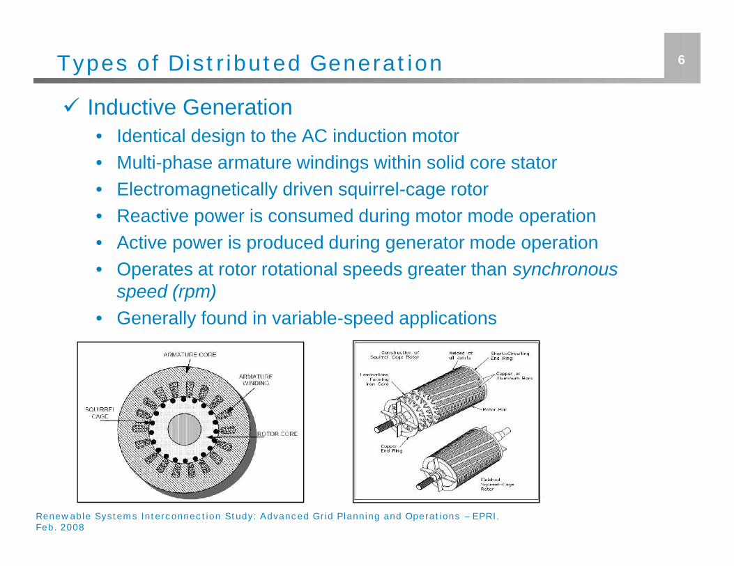
Inductive Generation• Identical design to the AC induction motor• Multi-phase armature windings within solid core stator• Electromagnetically driven squirrel-cage rotor• Reactive power is consumed during motor mode operation• Active power is produced during generator mode operation• Operates at rotor rotational speeds greater than synchronous
speed (rpm)• Generally found in variable-speed applications
Renewable Systems Interconnection Study: Advanced Grid Planning and Operations – EPRI,Feb. 2008
7Types of Distributed Generation
Synchronous Generation• Similar in design to inductive generator• Solid core stator designed with armature windings within laminated
slots• Rotor creates rotating magnetic flux via three methods
Permanent Magnets DC-powered electromagnets via slip rings/commutator system Brushless exciter alternator
• Induced current imposed upon armature windings• More costly than inductive generators due to:
Increased cost of permanent magnets Higher complexity in comparison to inductive motors Maintenance required for commutator and slip ring adjustments, replacements,
etc.
8Operating Characteristics
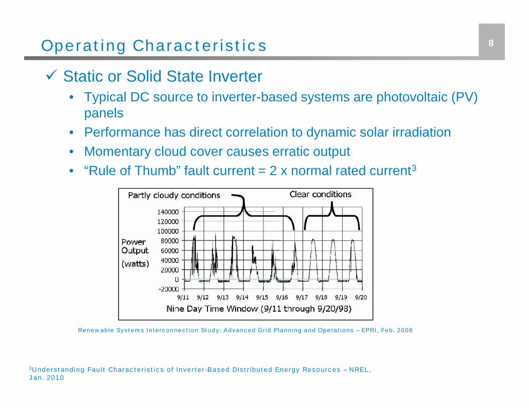
Static or Solid State Inverter• Typical DC source to inverter-based systems are photovoltaic (PV)
panels• Performance has direct correlation to dynamic solar irradiation• Momentary cloud cover causes erratic output• “Rule of Thumb” fault current = 2 x normal rated current3
Renewable Systems Interconnection Study: Advanced Grid Planning and Operations – EPRI, Feb. 2008
3Understanding Fault Characteristics of Inverter-Based Distributed Energy Resources – NREL,Jan. 2010
9Operating Characteristics
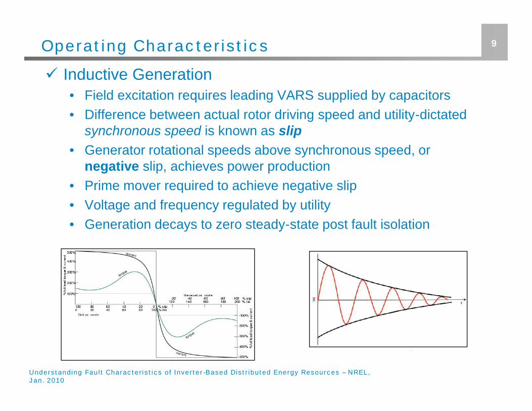
Inductive Generation• Field excitation requires leading VARS supplied by capacitors• Difference between actual rotor driving speed and utility-dictated
synchronous speed is known as slip• Generator rotational speeds above synchronous speed, or
negative slip, achieves power production• Prime mover required to achieve negative slip• Voltage and frequency regulated by utility• Generation decays to zero steady-state post fault isolation
Understanding Fault Characteristics of Inverter-Based Distributed Energy Resources – NREL,Jan. 2010
Operating Characteristics
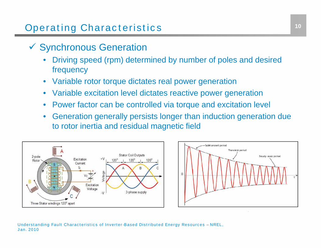
Synchronous Generation• Driving speed (rpm) determined by number of poles and desired
frequency• Variable rotor torque dictates real power generation• Variable excitation level dictates reactive power generation• Power factor can be controlled via torque and excitation level• Generation generally persists longer than induction generation due
to rotor inertia and residual magnetic field
10
Understanding Fault Characteristics of Inverter-Based Distributed Energy Resources – NREL,Jan. 2010
Benefits of Distributed Generation
Customer Benefits• Reduced apparent power consumption visible to utility, resulting in
reduced electric bill• If net metering is employed, excess energy may be exported back
to utility in exchange for billing credits
Utility Benefits• Reduced apparent power consumption may reduce overall losses• Depending upon characteristics of DG and high voltage feeder,
service transformer, and DG system, voltage support possible insome cases
• Dispatchable DG provides alternate sources of power generationto provide system redundancy and hardening Increased renewable energy DG systems (PV, Wind, Geothermal, etc.)
supports AEPS Act 213 initiatives
11
12Impacts of Distributed Generation
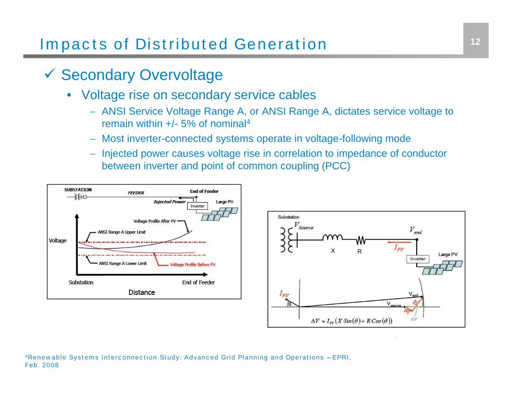
Secondary Overvoltage• Voltage rise on secondary service cables
ANSI Service Voltage Range A, or ANSI Range A, dictates service voltage toremain within +/- 5% of nominal4
Most inverter-connected systems operate in voltage-following mode Injected power causes voltage rise in correlation to impedance of conductor
between inverter and point of common coupling (PCC)
4Renewable Systems Interconnection Study: Advanced Grid Planning and Operations – EPRI,Feb. 2008
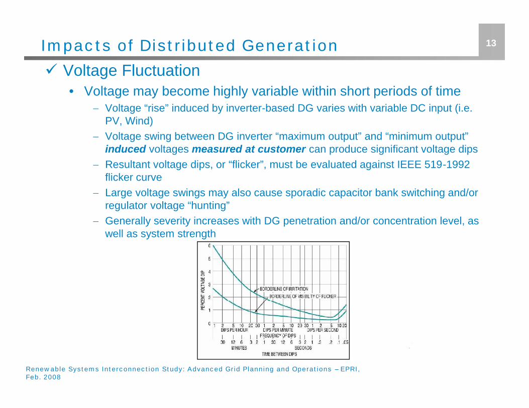
13Impacts of Distributed Generation Voltage Fluctuation
• Voltage may become highly variable within short periods of time Voltage “rise” induced by inverter-based DG varies with variable DC input (i.e.
PV, Wind) Voltage swing between DG inverter “maximum output” and “minimum output”
induced voltages measured at customer can produce significant voltage dips Resultant voltage dips, or “flicker”, must be evaluated against IEEE 519-1992
flicker curve Large voltage swings may also cause sporadic capacitor bank switching and/or
regulator voltage “hunting” Generally severity increases with DG penetration and/or concentration level, as
well as system strength
Renewable Systems Interconnection Study: Advanced Grid Planning and Operations – EPRI,Feb. 2008
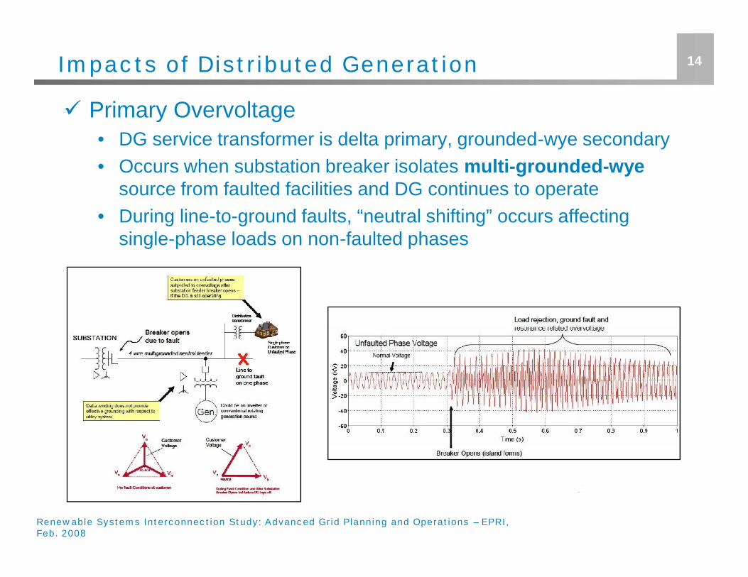
14Impacts of Distributed Generation
Primary Overvoltage• DG service transformer is delta primary, grounded-wye secondary• Occurs when substation breaker isolates multi-grounded-wye
source from faulted facilities and DG continues to operate• During line-to-ground faults, “neutral shifting” occurs affecting
single-phase loads on non-faulted phases
Renewable Systems Interconnection Study: Advanced Grid Planning and Operations – EPRI,Feb. 2008
15Impacts of Distributed Generation
"Effectively Grounded"• "Effectively grounded" is defined as:
“Grounded through a sufficiently low impedance (inherent or intentionallyadded, or both) so that the COG does not exceed 80%. This value is obtainedapproximately when, for all system conditions, the ratio of the zero-sequencereactance to the positive-sequence reactance, (X0/X1),is positive and ≤3, andthe ratio of zero-sequence resistance to positive-sequence reactance,(R0/X1), is positive and < 1”5
Key ratios to obtain “effectively grounded"o Coefficient of Ground (COG): (VL-G,fault / VL-L, nominal pre-fault) < 0.8 p.u. or 80%o R0/X1 < 1 and X0/X1 < 3
• Grounding compliance is maintained by utility source, but notnecessarily by DG during islanding conditions
• "Effectively grounded" must be maintained by DG source Compliance limits potential damage incurred by temporary “neutral shift” DG point of common coupling interconnection typically indicates severity of
grounding concern
5IEEE Std. 62.92.1-2000: Guide for the Application of Neutral Grounding in Electric UtilitySystems – Part 1 - Introduction
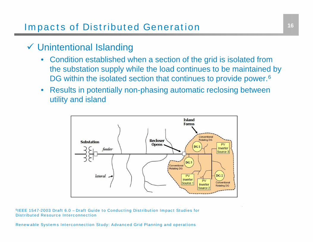
16Impacts of Distributed Generation
Unintentional Islanding• Condition established when a section of the grid is isolated from
the substation supply while the load continues to be maintained byDG within the isolated section that continues to provide power.6
• Results in potentially non-phasing automatic reclosing betweenutility and island
6IEEE 1547-2003 Draft 6.0 – Draft Guide to Conducting Distribution Impact Studies forDistributed Resource Interconnection
Renewable Systems Interconnection Study: Advanced Grid Planning and operations
17Impacts of Distributed Generation
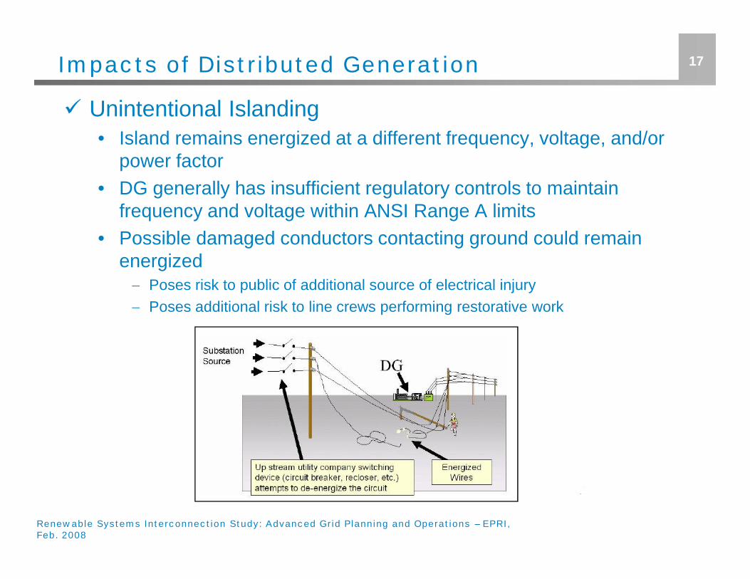
Unintentional Islanding• Island remains energized at a different frequency, voltage, and/or
power factor• DG generally has insufficient regulatory controls to maintain
frequency and voltage within ANSI Range A limits• Possible damaged conductors contacting ground could remain
energized Poses risk to public of additional source of electrical injury Poses additional risk to line crews performing restorative work
Renewable Systems Interconnection Study: Advanced Grid Planning and Operations – EPRI,Feb. 2008
18Impacts of Distributed Generation
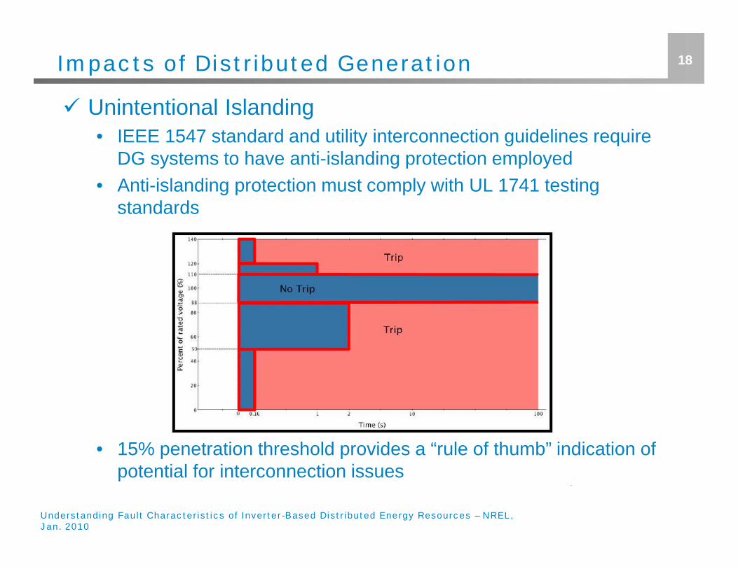
Unintentional Islanding• IEEE 1547 standard and utility interconnection guidelines require
DG systems to have anti-islanding protection employed• Anti-islanding protection must comply with UL 1741 testing
standards
• 15% penetration threshold provides a “rule of thumb” indication ofpotential for interconnection issues
Understanding Fault Characteristics of Inverter-Based Distributed Energy Resources – NREL,Jan. 2010
19Impacts of Distributed Generation
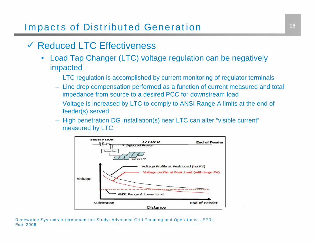
Reduced LTC Effectiveness• Load Tap Changer (LTC) voltage regulation can be negatively
impacted LTC regulation is accomplished by current monitoring of regulator terminals Line drop compensation performed as a function of current measured and total
impedance from source to a desired PCC for downstream load Voltage is increased by LTC to comply to ANSI Range A limits at the end of
feeder(s) served High penetration DG installation(s) near LTC can alter “visible current”
measured by LTC
Renewable Systems Interconnection Study: Advanced Grid Planning and Operations – EPRI,Feb. 2008
20Impacts of Distributed Generation
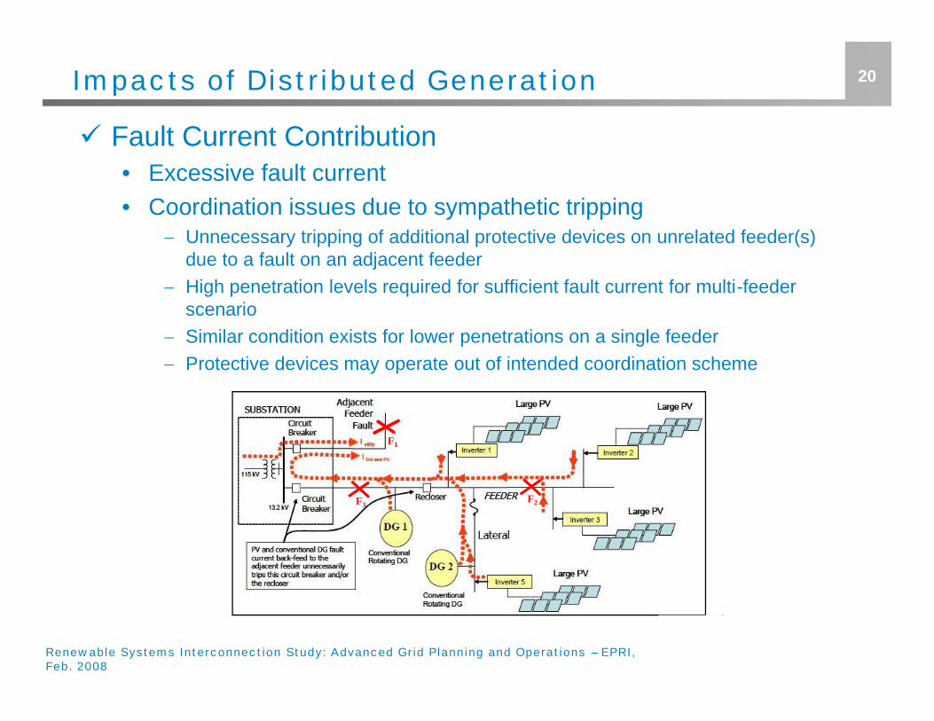
Fault Current Contribution• Excessive fault current• Coordination issues due to sympathetic tripping
Unnecessary tripping of additional protective devices on unrelated feeder(s)due to a fault on an adjacent feeder
High penetration levels required for sufficient fault current for multi-feederscenario
Similar condition exists for lower penetrations on a single feeder Protective devices may operate out of intended coordination scheme
Renewable Systems Interconnection Study: Advanced Grid Planning and Operations – EPRI,Feb. 2008
F1
F3F2
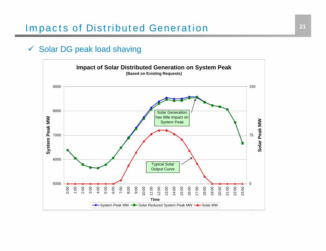
21Impacts of Distributed Generation
Impact of Solar Distributed Generation on System Peak[Based on Existing Requests]
5000
6000
7000
8000
9000
0:00
1:00
2:00
3:00
4:00
5:00
6:00
7:00
8:00
9:00
10:0
0
11:0
0
12:0
0
13:0
0
14:0
0
15:0
0
16:0
0
17:0
0
18:0
0
19:0
0
20:0
0
21:0
0
22:0
0
23:0
0
Time
Syst
em P
eak
MW
0
75
150
Sola
r Pea
k M
W
System Peak MW Solar Reduced System Peak MW Solar MW
Typical SolarOutput Curve
Solar Generationhas little impact on
System Peak
Solar DG peak load shaving
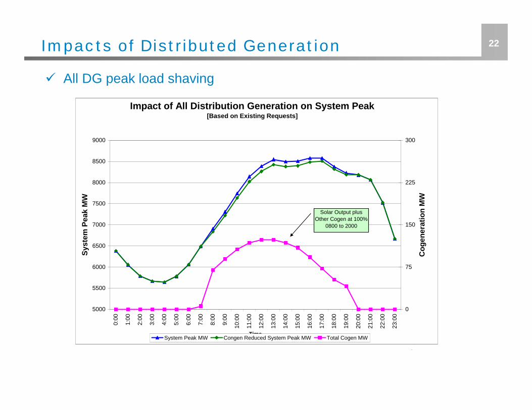
22
Impact of All Distribution Generation on System Peak[Based on Existing Requests]
5000
5500
6000
6500
7000
7500
8000
8500
9000
0:00
1:00
2:00
3:00
4:00
5:00
6:00
7:00
8:00
9:00
10:0
0
11:0
0
12:0
0
13:0
0
14:0
0
15:0
0
16:0
0
17:0
0
18:0
0
19:0
0
20:0
0
21:0
0
22:0
0
23:0
0
Time
Syst
em P
eak
MW
0
75
150
225
300
Cog
ener
atio
n M
W
System Peak MW Congen Reduced System Peak MW Total Cogen MW
Solar Output plusOther Cogen at 100%
0800 to 2000
Impacts of Distributed Generation
All DG peak load shaving
23Mitigation Methods
"Effectively Grounded"• Utility-interconnected DG systems must comply with “effectively
grounded" criteria Resolution: If system is found non-compliant, system zero sequence
impedance or positive sequence reactance must be modified.
• Ground reference absent due to delta primary, grounded-wyesecondary interconnection Resolution: Installation of isolation transformer or grounding bank (i.e. -
grounded-wye, delta), which provides neutral ground/zero sequence referenceto stabilize voltage.
Excessive Fault Current• Aggregate utility and DG fault current contribution exceeds
allowable limits Resolution: Current limiting equipment may be installed (i.e. series line
reactors) to increase impedance path to utility interconnection, reducing faultcurrent. Reduction in DG system generating capacity also a potential solution.
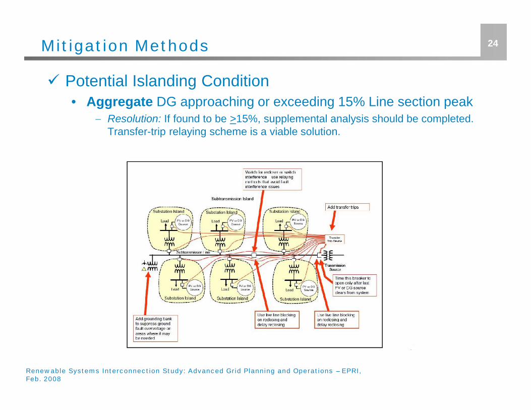
Mitigation Methods
Potential Islanding Condition• Aggregate DG approaching or exceeding 15% Line section peak
Resolution: If found to be >15%, supplemental analysis should be completed.Transfer-trip relaying scheme is a viable solution.
24
Renewable Systems Interconnection Study: Advanced Grid Planning and Operations – EPRI,Feb. 2008
25Mitigation Methods
Secondary Overvoltage• Voltage rise of utility-interactive inverter seen by customer is
greater than ANSI Range A upper limit Resolution: Reduce conductor impedance through placing inverter in closer
proximity of PCC, and/or use lower impedance conductor path.o Alternative option to reduce current injection (power output) of inverter onto system will also
provide a reduction of overvoltage.
Reduced LTC Effectiveness• DG interconnected in close proximity of LTC of feeder may lower
monitored downstream current Resolution: For aggregate lower penetrations, effects are typically insignificant.
Higher power output systems, or increasingly high aggregate penetrationlevels, may require relocation, greater dispersion, or reduced power output.
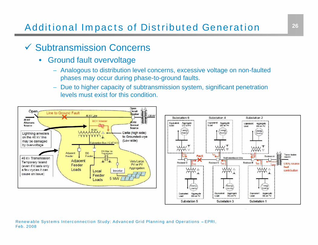
26Additional Impacts of Distributed Generation
Subtransmission Concerns• Ground fault overvoltage
Analogous to distribution level concerns, excessive voltage on non-faultedphases may occur during phase-to-ground faults.
Due to higher capacity of subtransmission system, significant penetrationlevels must exist for this condition.
Renewable Systems Interconnection Study: Advanced Grid Planning and Operations – EPRI,Feb. 2008
27Future Distribution System Design
Interactive volt/var regulation Adaptive protective relaying schemes Advanced islanding control Improved grounding compatibility Energy storage
Renewable Systems Interconnection Study: Advanced Grid Planning and Operations – EPRI,Feb. 2008
Summary
Distribution system is not designed to accommodatemultiple sources other than the substation
Future adaptations to the standard distribution systemdesign must be considered for proper integration with highDG penetration such as:• Interactive volt/var regulation• Transfer/trip communication• Communication amongst LTCs, regulators, inverter-based
systems, etc.
Effects upon local utility system varies upon characteristicsof the system, proposed DG, and its interconnection site
Severity of impacts are generally proportional topenetration level
28

29


![Author's personal copy - UAB Barcelonaicta.uab.cat/Etnoecologia/Docs/[410]-hunsberg.pdfAuthor's personal copy Livelihood impacts of biofuel crop production: Implications for governance](https://static.fdocuments.us/doc/165x107/5f33bfcc0da3f66a4c264305/authors-personal-copy-uab-410-hunsbergpdf-authors-personal-copy-livelihood.jpg)


