MICROSOFT AZURE STORSIMPLE 8000 SERIES DEPLOYMENT … · well as individuals who are familiar with...
24
MICROSOFT AZURE STORSIMPLE 8000 SERIES DEPLOYMENT BEST PRACTICES Version: 1.1
Transcript of MICROSOFT AZURE STORSIMPLE 8000 SERIES DEPLOYMENT … · well as individuals who are familiar with...

MICROSOFT AZURE STORSIMPLE 8000 SERIES
DEPLOYMENT BEST PRACTICES
Version: 1.1

Copyright
This document is provided "as-is". Information and views expressed in this document, including URL and other
Internet Web site references, may change without notice. Some examples depicted herein are provided for
illustration only and are fictitious. No real association or connection is intended or should be inferred.
This document does not provide you with any legal rights to any intellectual property in any Microsoft product.
You may copy, use and modify this document for your internal, reference purposes.
© 2016 Microsoft Corporation. All rights reserved.
Microsoft, Windows Azure, StorSimple, Hyper-V, Internet Explorer, Silverlight, SQL Server, Windows,
Windows PowerShell, and Windows Server are trademarks of the Microsoft group of companies. All other
trademarks are property of their respective owners.

3
Table of Contents
Table of Contents ................................................................................................................................................................................... 3
Introduction .............................................................................................................................................................................................. 5
Target audience ...................................................................................................................................................................................... 5
iSCSI network ........................................................................................................................................................................................... 6
Dual fabric iSCSI design ........................................................................................................................................................................ 6
Cloud connectivity .................................................................................................................................................................................. 8
Storage accounts performance .......................................................................................................................................................... 8
Initiator configuration for the StorSimple device ........................................................................................................................ 10
General BIOS settings.......................................................................................................................................................................... 10
NIC-PCIe slot allocation ....................................................................................................................................................................... 11
Server and NIC tuning ........................................................................................................................................................................ 12
Multipath input/output (MPIO) observations and configuration ........................................................................................... 13
Multisession MPIO configuration for mixed volume types and low latency ............................................................ 13
iSCSI session-path ID to IP mapping .................................................................................................................................... 13
iSCSI sessions ......................................................................................................................................................................................... 18
Volume Shadow Copy service (VSS) .............................................................................................................................................. 21
Appendix A: Creating virtual NICs on Windows Server ............................................................................................................22
Table of Tables
Table 1 Bios recommendations ........................................................................................................................................................ 10
Table 2 NIC settings............................................................................................................................................................................. 12
Table 3 Logical connection table for the selected locally pinned volume disk ID ............................................................ 14
Table 4 Logical connection table for the selected cloud tiered volume disk ..................................................................... 14
Table of Figures
Figure 1 iSCSI network topology for mixed volume types 7

4
Figure 3 Hypervisor iSCSI sessions .................................................................................................................................................. 19
Figure 4 iSCSI sessions with hyper NICs ........................................................................................................................................20

5
Introduction
This document will provide the best practices around how to build a high performance and low latency
environment while mixing volume types in your StorSimple 8000 series devices.
This document will cover:
• iSCSI network design
• Cloud Connectivity
• Initiator configuration with the StorSimple device
In the following sections, we will illustrate how to configure and optimize the previously mentioned settings to
achieve predictable performance with your StorSimple 8000 series device.
Target audience
This document is intended for storage administrators and solution architects who deploy StorSimple solutions as
well as individuals who are familiar with server hardware and software settings.

6
iSCSI network
Dual fabric iSCSI design
In order to deliver high availability, best performance, and lowest latencies, the following recommendations are
made independent from the network fabric speed.
Recommendation
Make sure that you can monitor and collect performance and utilization statistics from all your network
resources to pinpoint any component that behaves badly in your infrastructure.
The following reference design highlights the main components and their physical connectivity for highly
available, low latency, and high throughput iSCSI fabric.

7
Table 1 Port configuration
Server Vlan # Switch StorSimple 8000 Controller and Port #
Server1 10Gb NIC0 100 1 C0-Data2 and C1-Data2
Server1 10Gb NIC1 200 2 C0-Data3 and C1-Data3
Server1 1Gb NIC0 100 1 C0-Data2 and C1-Data2
Server1 1Gb NIC1 200 2 C0-Data3 and C1-Data3
Azure 300 3 C0 Data0 and C1 Data 0
Azure 400 4 C0 Data1 and C1 Data1
Figure 1 iSCSI network topology for mixed volume types
C0-D2
10Gb Switch #210Gb Switch #1
High Availability iSCSI Network Topology Example
Switch #3Switch #3 Switch #4Switch #4AzureAzure
Azure Vlan Azure Vlan
StorSimple 8000 Series Appliance
C1-D2
Server110Gb NIC0
Server 1Server 1
C0-D2
C0-D3
C0-D0
C0-D1
C1-D2
C1-D3
C1-D0
C1-D1
C0-D3
C1-D3
C0-D0 C1-D0
Server110Gb NIC1
Server11Gb NIC0
Server110Gb NIC1
8
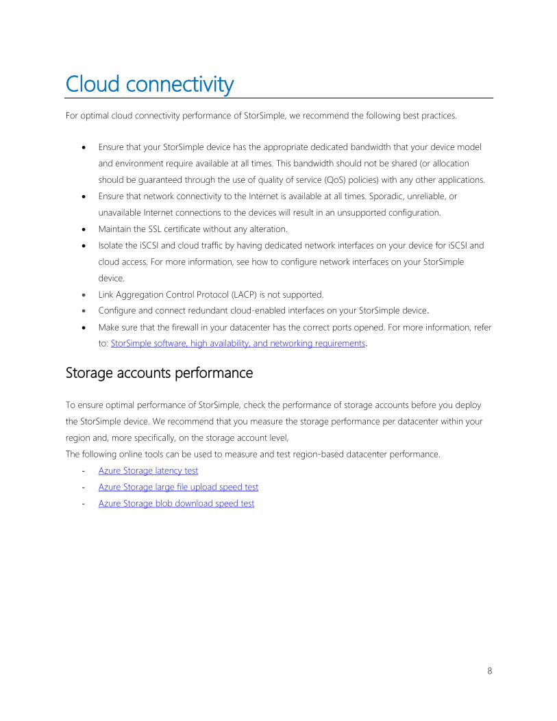
Cloud connectivity
For optimal cloud connectivity performance of StorSimple, we recommend the following best practices.
• Ensure that your StorSimple device has the appropriate dedicated bandwidth that your device model
and environment require available at all times. This bandwidth should not be shared (or allocation
should be guaranteed through the use of quality of service (QoS) policies) with any other applications.
• Ensure that network connectivity to the Internet is available at all times. Sporadic, unreliable, or
unavailable Internet connections to the devices will result in an unsupported configuration.
• Maintain the SSL certificate without any alteration.
• Isolate the iSCSI and cloud traffic by having dedicated network interfaces on your device for iSCSI and
cloud access. For more information, see how to configure network interfaces on your StorSimple
device.
• Link Aggregation Control Protocol (LACP) is not supported.
• Configure and connect redundant cloud-enabled interfaces on your StorSimple device.
• Make sure that the firewall in your datacenter has the correct ports opened. For more information, refer
to: StorSimple software, high availability, and networking requirements.
Storage accounts performance
To ensure optimal performance of StorSimple, check the performance of storage accounts before you deploy
the StorSimple device. We recommend that you measure the storage performance per datacenter within your
region and, more specifically, on the storage account level,
The following online tools can be used to measure and test region-based datacenter performance.
- Azure Storage latency test
- Azure Storage large file upload speed test
- Azure Storage blob download speed test
9
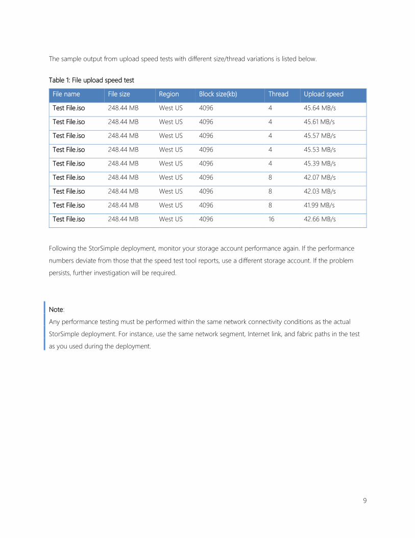
The sample output from upload speed tests with different size/thread variations is listed below.
Table 1: File upload speed test
File name File size Region Block size(kb) Thread Upload speed
Test File.iso 248.44 MB West US 4096 4 45.64 MB/s
Test File.iso 248.44 MB West US 4096 4 45.61 MB/s
Test File.iso 248.44 MB West US 4096 4 45.57 MB/s
Test File.iso 248.44 MB West US 4096 4 45.53 MB/s
Test File.iso 248.44 MB West US 4096 4 45.39 MB/s
Test File.iso 248.44 MB West US 4096 8 42.07 MB/s
Test File.iso 248.44 MB West US 4096 8 42.03 MB/s
Test File.iso 248.44 MB West US 4096 8 41.99 MB/s
Test File.iso 248.44 MB West US 4096 16 42.66 MB/s
Following the StorSimple deployment, monitor your storage account performance again. If the performance
numbers deviate from those that the speed test tool reports, use a different storage account. If the problem
persists, further investigation will be required.
Note:
Any performance testing must be performed within the same network connectivity conditions as the actual
StorSimple deployment. For instance, use the same network segment, Internet link, and fabric paths in the test
as you used during the deployment.
10
Initiator configuration for the StorSimple
device
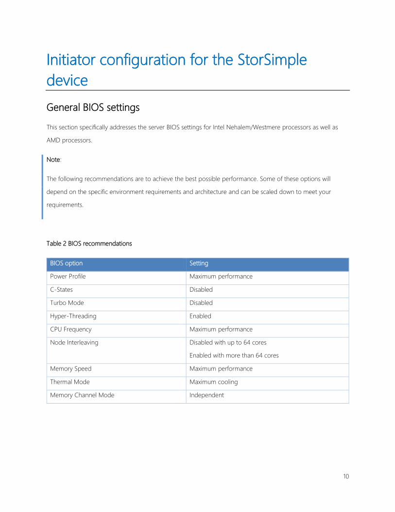
General BIOS settings
This section specifically addresses the server BIOS settings for Intel Nehalem/Westmere processors as well as
AMD processors.
Note:
The following recommendations are to achieve the best possible performance. Some of these options will
depend on the specific environment requirements and architecture and can be scaled down to meet your
requirements.
Table 2 BIOS recommendations
BIOS option Setting
Power Profile Maximum performance
C-States Disabled
Turbo Mode Disabled
Hyper-Threading Enabled
CPU Frequency Maximum performance
Node Interleaving Disabled with up to 64 cores
Enabled with more than 64 cores
Memory Speed Maximum performance
Thermal Mode Maximum cooling
Memory Channel Mode Independent

11
NIC-PCIe slot allocation
Given that every server is not designed the same way, it is important to understand your server’s hardware. The
hardware is the first building block towards creating a high performance and low latency environment.
PCIe has overcome some of the most important PCI limitations, such as having to negotiate all the devices to
the slowest device speed, by using the new PCI’s shared parallel bus architecture and by using point-to-point
connectivity. Keep in mind that not all PCIe interconnects are created equal. Most modern servers have one or
more 8, 16, or 32 lane interconnects. A PCIe lane can be visualized as lanes in a highway; theoretically the more
lanes, the faster the traffic moves. It is critical to make sure that you connect your Ethernet-NIC adapters to the
appropriate interconnect slot that your server’s hardware provides.
Connect your Ethernet adapters to interconnect slots that have a minimum of eight lanes for a single-port
adapter and 16 lanes for a dual-port adapter. In the case of a dual-adapter configuration, it is better to
distribute the load across each of the different non-uniform memory access (NUMA) nodes across your CPU
sockets. This is especially important to alleviate the additional load and latency that is created by switching
among NUMA nodes.
Just like you do with RAM by connecting DIMMs in pairs, it is important to distribute your NICs across the
NUMA node to balance the load across the nodes and avoid costly NUMA context switching across the nodes.
NICs that are connected on the wrong slots can cascade into 1-2 ms latencies and increase NUMA and CPU
utilization.

12
Server and NIC tuning
The following table shows some of the most common settings and the recommendations.
Table 3 NIC settings
Server and NIC settings Recommendation
Network resources like UDP checksums, TCP
checksums, Receive Segment Coalescing (RSC), and
Send Large Offload (LSO).
Set the maximum resources or set fixed value. Avoid
dynamic settings because these introduce higher
latencies and increase utilization on the server’s CPU
and NIC hardware.
System Management Interrupts (SMI) Set to disable. It is important to assess your server
needs first. If your server requires optimal latency,
you will lower latencies and increase throughputs at
a minimal CPU utilization increase.
Offload engines Set to enable. However, in some cases, such as
embedded NIC adapters, you should assess the
benefits.
Receive Windows autotuning Set to disable. If required, have a core processor that
shares CPU cache to handle the network adapter
interrupts and deferred procedure calls. This can be
managed from the NIC driver or Windows
PowerShell.
Receive-Side Scaling (RSS) Set the starting RSS processor to the first CPU in
each NUMA node.
Enable interrupt moderation Set to disable to achieve the lowest connectivity
latencies. Be aware that this will consume additional
CPU interrupts per I/O, because the I/O will not be
coalesced. For more information, follow the tuning
recommendations from your NIC manufacturer.
13
Multipath input/output (MPIO) observations and configuration
As with any storage solution, carefully assess and understand your workload and hardware to properly assess
your requirements and design the solution that best fits your workload. As a general rule, it’s usually not a good
practice to mix workloads. The closer to the performance edge you tune a system, the more difficult it is to
maintain, the room for error declines, and it’s more difficult to shift workloads and evolve the system. As always,
a simple system architecture is generally better than a complex one.
In previous storage schemes, system admins defined workloads as random or sequential. The introduction of
hybrid arrays adds a third category, cloud, mainly because of the difference in latencies that is incurred when
spanning I/Os to the cloud. The Least Queue Depth or Least Blocks load-balancing algorithms usually will take
care of most solutions and workloads. There are cases where a more complex design is appropriate to meet the
requirements. In the case of mixed loads, such as the low latency local volumes and cloud-tiered volumes, the
best way to solve the workload latency disparity is to dedicate or assign iSCSI sessions to each of the different
workloads. When a host serves I/Os to both tiered volumes and local volumes, we would like to have a one set
of paths that’s dedicated to the low latency workloads and a different set of paths that’s dedicated to the tiered
volumes. The most deterministic way to achieve this is to use MPIO’s Weighted Paths. In the following section,
we will illustrate this configuration.
Multisession MPIO configuration for mixed volume types and low latency
For a multisession MPIO configuration that uses mixed volumes, we recommend the Least Queue Depth or
Least Blocks algorithms because these are simpler to troubleshoot and maintain.
The following steps illustrate the configuration for one locally pinned volume and one tiered volume. The
configuration minimizes crosstalk, preserves high availability, and minimizes failover.
iSCSI session-path ID to IP mapping
1. Type Diskmgmt.msc to open the Windows Disk Management console. Note the disk ID whose
configuration you want to modify.
2. Type iscsicpl.exe to open the iSCSI Initiator Properties dialog box and then select your StorSimple
target.
a. In the iSCSI Initiator Properties dialog box, click Properties.
b. In the Properties dialog box, click MCS.

14
c. In the Multiple Connected Session (MCS) dialog box, for each session ID, note the session-path
ID, source IP, and destination IP. Repeat for all the sessions.
Table 4 Logical connection table for the selected locally pinned volume disk ID
Speed iSCSI session ID Source IP Target IP Disk ID MPIO policy Weight
10 Gb 008 10.10.172.61 10.10.172.1 Low Latency
Local Disk
Weighted Path 0
10 Gb 009 10.10.172.61 10.10.172.2 Low Latency
Local Disk
Weighted Path 0
1 Gb 00a 10.10.172.62 10.10.172.1 Low Latency
Local Disk
Weighted Path 5000
1 Gb 00b 10.10.172.62 10.10.172.2 Low Latency
Local Disk
Weighted Path 5000
*This shows just one side, that is half, of the connections for clarity. In a high availability configuration,
you would have twice the connections and NIC ports.
Table 5 Logical connection table for the selected tiered volume disk
Speed iSCSI session ID Source IP Target IP Disk ID MPIO policy Weight
10 Gb 008 10.10.172.61 10.10.172.1 Tiered volume
disk
Weighted Path 5000
10 Gb 009 10.10.172.61 10.10.172.2 Tiered volume
disk
Weighted Path 5000
1 Gb 00a 10.10.172.62 10.10.172.1 Tiered volume
disk
Weighted Path 0

15
1 Gb 00b 10.10.172.62 10.10.172.2 Tiered volume
disk
Weighted Path 0
*This shows just one side, that is half, of the connections for clarity. In a high availability configuration,
you would have twice the connections and NIC ports.
In this case, preferably, the locally pinned volume will use the 10 GB NIC, and the tiered volume will use
the 1 GB NIC.
3. In the iSCSI Initiator Properties dialog box, select your StorSimple target, and then click Properties. In
the Properties dialog box, click Devices.
4. In the Devices dialog box, highlight the device that you want to modify, and then click MPIO.
5. In the Device Details dialog box, in the dropdown list for Load balance policy, select Weighted Paths,
and then click Edit.

16
6. Edit each of the 1 Gb path-session IDs that end with (00a,00b) from 0 to 5000. This will ensure that the
selected Drive ID uses the 10 Gb NIC session. In case the connectivity is lost, it will switch to 1 Gb.

17
7. Click Apply, and then click OK until you have exited iSCSI Initiator Configuration.
If you want to share the 10 Gb NICs the next time you assign a volume to this host, you will repeat these steps. If
you want to isolate the new volume (like in the case of a tiered volume) to the 1 Gb NICs, you will do the same
but reverse the path weights. The Path-Session IDs that end with 008 and 009 will have weights of 0 and 00a
respectively, and 00b will have a weight of 5000.

18
iSCSI sessions
Failover and load-balancing configuration is important when you deploy a storage solution in your environment
to achieve optimal resource utilization, throughput, and response time. By using multiple sessions, you can
deliver a high-quality and reliable storage service with failover and load-balancing capability.
There are some cases where you can modify the queues without increasing the sessions, like when you work
with iSCSI host-bus adapters (HBAs) and VMware. On some iSCSI HBAs, which are not supported at the
moment, you can increase the queues by using the iSCSI HBA’s management interface.
Lastly, you can modify queue depths by using your server OEM virtualization stack or hypervisor virtual switch to
virtualize the NICs.
If you are confident that your queues at the host are building and this not due to either a network or appliance
saturation, you might want to want increase the number of queued I/Os. You can create “Hyper-NICs” that are
presented to the physical host. In the case of a virtual machine, you can add a couple of virtual network
adapters that are presented to the virtual machine.
This will increase your host’s overall ability to distribute I/Os across multiple sessions. It is extremely important to
remember that, in the vast majority of cases, we do not recommend an increase in the host’s ability to queue
I/Os because an increase can starve other hosts’ I/O and increase I/O jitter. After you increase the I/O queues,
make sure that the other servers have not been impacted.

19
The following diagram shows the logical configuration of multiple vNICs in a hypervisor environment
Figure 2 Hypervisor iSCSI sessions
iSCSI Volume
Azure
VM1 with high latency
vNIC2
Hypervisor
vNIC1
Hypervisor iSCSI IO queue management
iSCSI Volume
Azure
VM1 with lower latencyafter adding vNICs
vNIC2 vNIC3 vNIC4vNIC1
Hypervisor
vNIC= Hypervisor virtual NIC

20
A similar workaround is true for a bare metal host if your server vendors supports it.
Figure 3 iSCSI Sessions with Hyper NICs
iSCSI Volume
Azure
Standard Server OS
h-NIC2
Bare metal hardware
h-NIC1
Hypervisor iSCSI IO queue management
iSCSI Volume
Azure
Standard Server OS with lower latencyafter adding the server OEM s vNICs
hNIC2 hNIC3 hNIC4hNIC1
Bare metal hardware
hNIC = hyperNIC like HP Virtual Connect or IBM s virtual Fabrics
Note
The number of iSCSI sessions has to be well planned to provide an equal distribution of resources among all the
initiators with relation to the storage subsystem.

21
Volume Shadow Copy service (VSS)
When using Volume Shadow Copy service (VSS) in StorSimple volumes, we recommend that the diff area for
VSS be in a StorSimple locally pinned volume. You could also use an external disk with sufficient capacity for
your diff area.
For more information on VSS, go to Best Practices for Shadow Copies of Shared Folders
Terms:
• Volume Shadow Copy service (VSS) - This service coordinates the actions required to create a
consistent shadow copy of the data to be backed up. The shadow copy also known as a snapshot, is a
block-level set of information that represents the differences between the current content and content
from a previous point in time.
• Diff Area – This area is the storage space allocated on a volume to maintain the snapshots of contents
of the shared folder. The allocation is done by the shadow copies of shared folders.

22
Appendix A: Creating virtual NICs on Windows
Server Creation of virtual network interfaces is available with Windows Server 2012 or later and relies on Hyper-V virtual
switches, this feature provides the ability to separate between different traffic types while utilizing a single high
bandwidth physical network interface 10 Gbps or more.
Before proceeding with converged networks creation and QoS configuration some terminologies has to be
described first
▪ MaximumBandwidth<Int64>:Specifies the maximum bandwidth, in bits per second, for the virtual
network adapter. The specified value is rounded to the nearest multiple of eight. Specify zero to disable
the feature.
▪ MinimumBandwidthAbsolute<Int64>: Specifies the minimum bandwidth, in bits per second, for the
virtual network adapter. The specified value is rounded to the nearest multiple of eight. For predictable
behavior, you should specify a number larger than 100Mbps.
▪ MinimumBandwidthWeight<UInt32>: Specifies the minimum bandwidth, in terms of relative weight, for
the virtual network adapter. The weight describes how much bandwidth the virtual network adapter
intends to have in relative to other virtual network adapters connected to the same virtual switch. The
range of the value is 0 and 100. Specify zero to disable the feature.
▪ DefaultFlowMinimumBandwidthAbsolute<Int64> “To be used with Virtual Switches only set-
vmswitch”: Specifies the minimum bandwidth, in bits per second, that is allocated to a special bucket
called “default flow.” Any traffic sent by a virtual network adapter that is connected to this virtual switch
and does not have minimum bandwidth allocated will be filtered into this bucket. Specify a value for
this parameter only if the minimum bandwidth mode on this virtual switch is absolute. By default, the
virtual switch allocates 10% of the total bandwidth, which depends on the physical network adapter it
binds to, to this bucket. For example, if a virtual switch binds to a 1GbE network adapter, this special
bucket can use at least 100Mbps. If the value is not multiples of 8 it will be rounded down to the nearest
number that is. For example, input 1234567 will be converted to 1234560.
Now we will start to create and Virtual Switch, different virtual networks with different QoS bandwidth allocation
for each network as per the below table;

23
VMSW0
1
NIC1 NIC2 NIC3 NIC4
MaximumBandwidth 100000000
0
100000000
0
100000000
0
200000000
0
MinimumBandwidthAbsolute
MinimumBandwidthWeight 20 40 20 20
DefaultFlowMinimumBandwidthAbsolut
e
20
First step to configure the above network requirements is to create the virtual switch VMSW01 using physical
adapter LAN01 and set the DefaultFlowMinimumBandwidthAbsolute to be 20, to do so in windows PowerShell
run the following command “This switch will be used by Virtual Machines for guest networking access”:
New-VMSwitch “VMSW01″ -MinimumBandwidthMode weight -NetAdapterName “LAN01” –
AllowManagement 1
Set-VMSwitch “VMSW01″ -DefaultFlowMinimumBandwidthWeight 20
2. Now we will create multi iSCSI vNICs, to do so in windows PowerShell run the following commands:
Add-VMNetworkAdapter -ManagementOS -Name “NIC1” -SwitchName VMSW01″
Add-VMNetworkAdapter -ManagementOS -Name “NIC2” -SwitchName “VMSW01″
Add-VMNetworkAdapter -ManagementOS -Name “NIC3” -SwitchName “VMSW01″
Add-VMNetworkAdapter -ManagementOS -Name “NIC4” -SwitchName “VMSW01″
3. Then the final step is to set the QoS bandwidth allocation limits on each of the created networks, to do so in
windows PowerShell run the following commands:
Set-VMNetworkAdapter -ManagementOS -Name “NIC1” -MinimumBandwidthWeight 20 –
MaximumBandwidth 100000000
Set-VMNetworkAdapter -ManagementOS -Name “NIC2” -MinimumBandwidthWeight 20 –
MaximumBandwidth 1000000000
Set-VMNetworkAdapter -ManagementOS -Name “NIC3” -MinimumBandwidthWeight 20 –
MaximumBandwidth 1000000000

24
Set-VMNetworkAdapter -ManagementOS -Name “NIC4” -MinimumBandwidthWeight 20 –
MaximumBandwidth 200000000
To get all of the created virtual network adapters settings run the following PowerShell command:
Get-VMNetworkAdapter -all -Name * | fl
For more info about vmnetworkadpater https://technet.microsoft.com/en-us/library/hh848564.aspx