Microprocessors A microprocessor is essentially a computer on a single chip. It is also an example...
47
Microprocessors A microprocessor is essentially a computer on a single chip. It is also an example of a complex finite state machine or clocked sequential circuit. • The first microprocessor was introduced around 1970 • By 1974 the 8-bit Intel 8080 and Motorola 6800 were introduced • By 1978 the 16-bit Intel 8086 and Motorola 68000 were introduced Microprocessors have continued to develop along two lines : 1) Performance – modern computers are based on powerful microprocessors where the focus is on speed and processing and storage of large amounts of data. 2) Integration – smaller microprocessors that include built-in memory and interface circuitry, or microcontrollers, are often integrated into applications, such as appliances, vehicles, equipment, etc. The focus here is reduced size, reduced cost, and a reduced chipset (onboard 1 Microprocessors EGR 270 – Fundamentals of Computer Engineering
-
Upload
ella-wright -
Category
Documents
-
view
221 -
download
0
Transcript of Microprocessors A microprocessor is essentially a computer on a single chip. It is also an example...

Microprocessors
A microprocessor is essentially a computer on a single chip. It is also an example of a complex finite state machine or clocked sequential circuit.
• The first microprocessor was introduced around 1970• By 1974 the 8-bit Intel 8080 and Motorola 6800 were introduced• By 1978 the 16-bit Intel 8086 and Motorola 68000 were introduced
Microprocessors have continued to develop along two lines:
1) Performance – modern computers are based on powerful microprocessors where the focus is on speed and processing and storage of large amounts of data.
2) Integration – smaller microprocessors that include built-in memory and interface circuitry, or microcontrollers, are often integrated into applications, such as appliances, vehicles, equipment, etc. The focus here is reduced size, reduced cost, and a reduced chipset (onboard memory, for example, rather than separate memory chips). The general public is less familiar with microcontrollers, although ten times more microcontrollers are sold than microprocessors!
1Microprocessors EGR 270 – Fundamentals of Computer Engineering

Microcontroller evolution
Microcontrollers have continued to evolve. Using Motorola as an example:• Recall that in 1974 the Motorola 6800 was introduced• Later versions included the Motorola 6801, 6802, and 6808.• In 1985 the Motorola 68HC11 was introduced (including several versions)• In 1996 the Motorola 68HC12 was introduced.• July 2004 the Motorola microcontroller division broke off into a new
company: Freescale Semiconductor, Inc
68HC11-based applications – just to name a few:• Chrysler transmission and engine control modules• Ford digital instrument cluster• Chevrolet engine control modules• Canon cameras• Motorola phone systems• AIM portable gas detectors• StairMaster’s exercise machines
2Microprocessors EGR 270 – Fundamentals of Computer Engineering

3Microprocessors EGR 270 – Fundamentals of Computer Engineering
a few words from their web site (www.freescale.com)
Freescale is a leader in embedded processing solutions for the automotive, consumer, industrial and networking markets. From microcontrollers and microprocessors to sensors, analog ICs and connectivity, our technologies are fueling the next great wave of innovation. A few applications are listed below:
ConsumerAugmented RealityBoiler Heating ControlCooking ProductsDishwashersDryersRefrigeratorsSmartphones Washing Machines…
AutomotiveAlternator RegulatorBasic/Low Line Instrument ClusterBasic Rear View CameraBattery MonitoringBreaking and Stability ControlDoors, Window Lift and Seat Control DSI Airbag SystemElectric Power Steering…
Medical/Health CareBlood Glucose MonitorsBlood Pressure MonitorsContinuous Glucose Monitor Machine DefibrillatorsDigital StethoscopeDigital X–RayElectrocardiograph (ECG)…

Microcontroller boards
Microcontrollers are often available on circuit boards for learning and building
prototypes of designs. Microcontroller boards might contain:• Microcontroller• Crystal clock generator• Power supply (or regulator)• Input/output connections for downloading programs, reading keyboard inputs, and
displaying outputs• Connection points the microcontroller’s input and output pins• Additional memory
68HC11 Microcontroller Boards – just to name a few:• M68HC11EVBU (Motorola Evaluation Board)• 68HC11F1 by Allen Systems, Inc. (www.allen-systems.com)• Handy Board – developed and licensed by MIT (www.handyboard.com)• F68HC11 single chip evaluation board by NewMicros (www.newmicros.com) • MicroStamp11 by Technological Arts, Inc. (www.technologicalarts.com) – used in
EGR270 and EGR 262
4Microprocessors EGR 270 – Fundamentals of Computer Engineering

MicroStamp11
The MicroStamp11 is a microcontroller built by Technological Arts and is based on the Motorola 68HC11 microcontroller.
Technological Arts states that the MicroStamp11 is the world’s smallest 68HC11 microcontroller module.
The MicroStamp11 is about the size of a postage stamp!
5Microprocessors EGR 270 – Fundamentals of Computer Engineering

MicroStamp11 Breadboard Setup
The MicroStamp11 is easily used on a breadboard with two modules:• MicroStamp11 Module – fitted with a 20-pin connector that plugs into a
breadboard• USB-to-MCU Interface Module – allows for serial communication using a
USB port on a computer. The USB connection can also be used to provide power (5V) to the breadboard. A few wires are required as shown below.
MicroStamp11 Module USB-to-MCU Interface Module
6Microprocessors EGR 270 – Fundamentals of Computer Engineering

MicroStamp11 Features (reference: www.technologicalArts.com)
7Microprocessors EGR 270 – Fundamentals of Computer Engineering
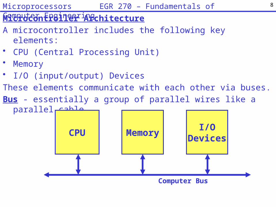
Microcontroller Architecture
A microcontroller includes the following key elements:• CPU (Central Processing Unit)• Memory• I/O (input/output) Devices
These elements communicate with each other via buses.
Bus - essentially a group of parallel wires like a parallel cable
CPU MemoryI/O
Devices
Computer Bus
8Microprocessors EGR 270 – Fundamentals of Computer Engineering

More detail is added to each element of microcontroller as illustrated below:
Control Unit
ROMI/O
Ports
Data Bus
ALU
Special Registers
Gen. Purpose Registers
CPU
RAM
Memory I/O Devices
SecondaryMemory
Address Bus
Control Bus
9Microprocessors EGR 270 – Fundamentals of Computer Engineering

Register – a temporary place to store data (to transfer data, manipulate data, etc.). An 8-bit register can be easily formed using 8 flip-flops.
Special Registers – Program Counter (PC), Stack Pointer (SP), Index Register (IR), Memory Address Register (MAR), Condition Code Register (CCR), etc
General Purpose Registers – Handy places to store values used in computations
ALU (Arithmetic Logic Unit) - performs operations such as Add, Subtract, AND, OR, XOR, complements, etc. The ALU typically has special registers (sometimes called accumulators) associated with it.
RAM (Random Access Memory) – used as a scratchpad to store variables during the execution of a program. Data stored in RAM is lost when the microcontroller is powered down.
ROM (Read Only Memory) - used to store permanent programs and data. Data stored in ROM is not erased when the microcontroller is powered down, so programs that you save will still be in memory for future use.
10Microprocessors EGR 270 – Fundamentals of Computer Engineering

68HC11 Architecture (simplified)
B MAR
ControlUnit
PC
8
ALU16
Memory
Data Bus
Address Bus
IR
A
Notes:• A and B registers (or accumulators) are used in arithmetic operations• The control unit connected to each element via control bus• An external clock connected to each element
11Microprocessors EGR 270 – Fundamentals of Computer Engineering

68HC11 Registers
Condition Code Register (CCR)Bits in the CCR are checked for carries, overflows, signs, interrupts, etc. More on this later.C – Carry from MSB V – 2’s complement overflow errorZ – Zero N – NegativeI – I-Interrupt H – Half-Carry from Bit 3X – X-Interrupt S – Stop Disable
7 A 0 7 B 0
15 PC 0
15 SP 0
15 Y 0
15 X 0
15 D 0
8-Bit accumulators A and B
16-Bit double accumulator D
Index register X
Index register Y
Stack pointer
Program Counter
S X H I N Z V C Condition Code Register
12Microprocessors EGR 270 – Fundamentals of Computer Engineering

Assembly LanguageMicrocontrollers are programmed using a precise set of instructions available in their instruction set. The 68HC11, for example, has an instruction set that contains about 150 different instructions (see the course web site for a complete list).Op Code – each instruction has a particular binary code called an op code that is used to execute the instruction. Programs written using op codes are called machine code. Assembly language – programs written in assembly language use symbols or letters (mnemonics) to represent op codes so that they are more readable. Assemblers convert assembly language programs into machine code.Example: The assembly language instruction LDAA is used to “load the A Accumulator”. LDAA is a mnemonic that represents the op code 86. In the example below, the hexadecimal number 43 is loaded into Accumulator A.
LDAA #$43 Assembler 864316 or10000110 010000112
Machine CodeAssembly Language
Op Code (86)for loadingAccumulator A Operand (data)
Mnemonic (easier to remember than 86)
13Microprocessors EGR 270 – Fundamentals of Computer Engineering

14Microprocessors EGR 270 – Fundamentals of Computer Engineering
…
The op code (86) for LDAA is highlighted below from the instruction set for the 68HC11 (full list available on course website)

High-Level Language versus Low-Level LanguageC++ is a high-level language. High-level languages are independent of the platform (type of computer), although when you compile a C++ program you generally compile it for a particular “target,” such as a Windows application.
Assembly languages are low-level languages. Each type of microprocessor has its own assembly language, so there are hundreds of different assembly languages (although they have many common features). We will learn assembly language for the 68HC11.
Programming in assembly language is different from programming in high-level languages in that the user must have knowledge of:• Microprocessor registers• Available memory addresses for temporary storage of information• Available memory addresses for permanent storage of programs
15Microprocessors EGR 270 – Fundamentals of Computer Engineering

Example: High-Level Language versus Low-Level LanguageSuppose that we wanted to store the decimal constants 10, 20, and 30 and find their sum.
C++ program:A = 10;B = 20;C = 30;Sum = A + B + C;
68HC11 program:LDAA #$0A ;Load hexadecimal $0A into register ASTAA $01 ;Store in memory location M[$01]LDAA #$14STAA $02LDAA #$1ESTAA $03ADDA $01 ;Add the contents of M[$01] to AADDA $02 ;Add the contents of M[$02] to ASTAA $04
Memory Address Contents
$01 $0A
$02 $14
$03 $1E
$04
What value is stored
here?
16Microprocessors EGR 270 – Fundamentals of Computer Engineering

Format for 68HC11 instructionsIn the last example, each 68HC11 instruction had two parts: the mnemonic for the op code and the operand.
Actually, different 68HC11 instructions may require 0, 1, or 2 operands.The general form for any instruction is: <Label> op code <0, 1, or 2 operands> ; <comment>
where < > is used to indicate an optional item.Examples:Label op codeoperand(s) comments
ABA ;add A and B and store results in ALDAA #$0A ;load hexadecimal $0A to contents of reg. A
L1 BRA L1 ;infinite loop (branch to L1)STAA $00 FF ;store A at extended (2-byte) address
M[$00FF]
Example: LDAA #$0A
op codemnemonic
operand
17Microprocessors EGR 270 – Fundamentals of Computer Engineering
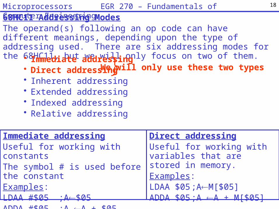
68HC11 Addressing ModesThe operand(s) following an op code can have different meanings, depending upon the type of addressing used. There are six addressing modes for the 68HC11, but we will only focus on two of them.
• Immediate addressing• Direct addressing• Inherent addressing• Extended addressing• Indexed addressing• Relative addressing
We will only use these two types
Immediate addressingUseful for working with constantsThe symbol # is used before the constantExamples:LDAA #$05 ;A$05ADDA #$05 ;A A + $05
Direct addressingUseful for working with variables that are stored in memory.Examples:LDAA $05 ;AM[$05]ADDA $05 ;A A + M[$05]
18Microprocessors EGR 270 – Fundamentals of Computer Engineering
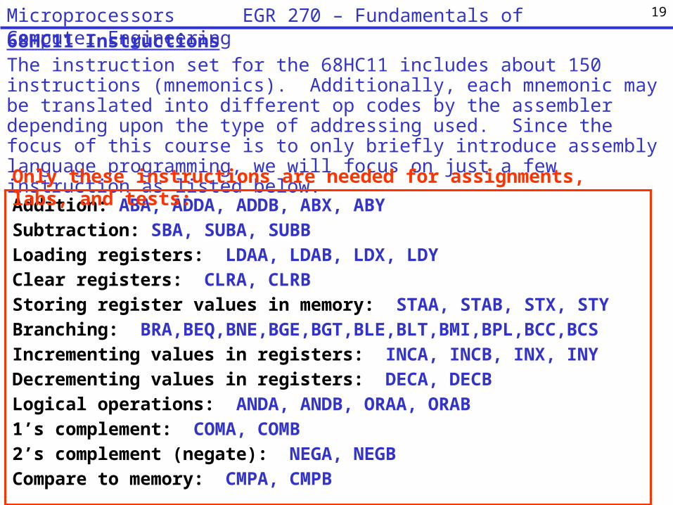
68HC11 InstructionsThe instruction set for the 68HC11 includes about 150 instructions (mnemonics). Additionally, each mnemonic may be translated into different op codes by the assembler depending upon the type of addressing used. Since the focus of this course is to only briefly introduce assembly language programming, we will focus on just a few instruction as listed below.
Addition: ABA, ADDA, ADDB, ABX, ABYSubtraction: SBA, SUBA, SUBBLoading registers: LDAA, LDAB, LDX, LDYClear registers: CLRA, CLRBStoring register values in memory: STAA, STAB, STX, STYBranching: BRA,BEQ,BNE,BGE,BGT,BLE,BLT,BMI,BPL,BCC,BCS Incrementing values in registers: INCA, INCB, INX, INYDecrementing values in registers: DECA, DECBLogical operations: ANDA, ANDB, ORAA, ORAB1’s complement: COMA, COMB2’s complement (negate): NEGA, NEGBCompare to memory: CMPA, CMPB
Only these instructions are needed for assignments, labs, and tests:
19Microprocessors EGR 270 – Fundamentals of Computer Engineering
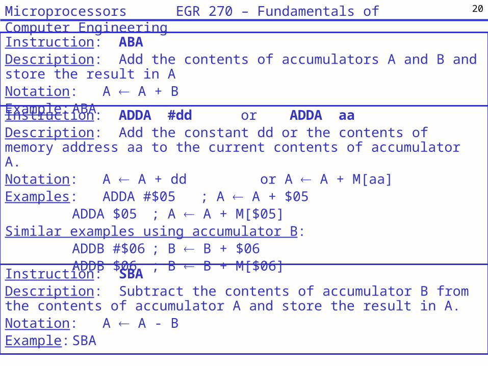
Instruction: ABADescription: Add the contents of accumulators A and B and store the result in ANotation: A A + BExample: ABA
Instruction: ADDA #dd or ADDA aaDescription: Add the constant dd or the contents of memory address aa to the current contents of accumulator A.Notation: A A + dd or A A + M[aa] Examples: ADDA #$05 ; A A + $05
ADDA $05 ; A A + M[$05]Similar examples using accumulator B:
ADDB #$06 ; B B + $06ADDB $06 ; B B + M[$06]
Instruction: SBADescription: Subtract the contents of accumulator B from the contents of accumulator A and store the result in A.Notation: A A - BExample: SBA
20Microprocessors EGR 270 – Fundamentals of Computer Engineering
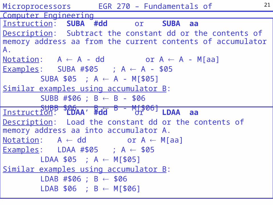
Instruction: SUBA #dd or SUBA aaDescription: Subtract the constant dd or the contents of memory address aa from the current contents of accumulator A.Notation: A A - dd or A A - M[aa] Examples: SUBA #$05 ; A A - $05
SUBA $05 ; A A - M[$05]Similar examples using accumulator B:
SUBB #$06 ; B B - $06SUBB $06 ; B B - M[$06]
Instruction: LDAA #dd or LDAA aaDescription: Load the constant dd or the contents of memory address aa into accumulator A.Notation: A dd or A M[aa] Examples: LDAA #$05 ; A $05
LDAA $05 ; A M[$05]Similar examples using accumulator B:
LDAB #$06 ; B $06LDAB $06 ; B M[$06]
21Microprocessors EGR 270 – Fundamentals of Computer Engineering
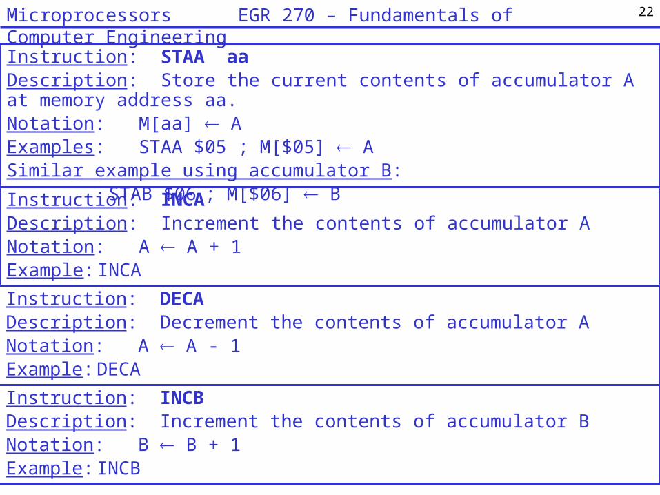
Instruction: STAA aaDescription: Store the current contents of accumulator A at memory address aa.Notation: M[aa] AExamples: STAA $05 ; M[$05] ASimilar example using accumulator B:
STAB $06 ; M[$06] BInstruction: INCADescription: Increment the contents of accumulator ANotation: A A + 1Example: INCA
Instruction: INCBDescription: Increment the contents of accumulator BNotation: B B + 1Example: INCB
Instruction: DECADescription: Decrement the contents of accumulator ANotation: A A - 1Example: DECA
22Microprocessors EGR 270 – Fundamentals of Computer Engineering

Example: Write a program to swap the values stored in memory locations M[$10] and M[$11].
23Microprocessors EGR 270 – Fundamentals of Computer Engineering

Example: Write a program to rotate the values stored in memory locations M[$10], M[$11], and M[$12]. In other words:
M[$10] M[$11]M[$11] M[$12]M[$12] M[$10]
24Microprocessors EGR 270 – Fundamentals of Computer Engineering

Branching (conditional structures) Branching is much cruder in assembly language programming than with high-level languages such as C++. Branching is generally accomplished based on the results of the Condition Code Register (CCR), which is called the status register in some microcontrollers. Bits of the CCR may be set or cleared based on the results of the last instruction executed.
Notes on the Condition Code Register (CCR):Some instructions may explicitly set or clear condition code bits. We will only focus on three bits in the CCR:Z = 1 if the result was zero, Z = 0 otherwiseN = 1 if the result was negative, N = 0 otherwiseC = 1 if the result generated a carry or borrow, C = 0 otherwise
S
Condition Code Register
X H I N Z V C
C – Carry from MSBV – 2’s complement overflow errorZ – ZeroN – NegativeI – I-InterruptH – Half-Carry from Bit 3X – X-InterruptS – Stop Disable
25Microprocessors EGR 270 – Fundamentals of Computer Engineering
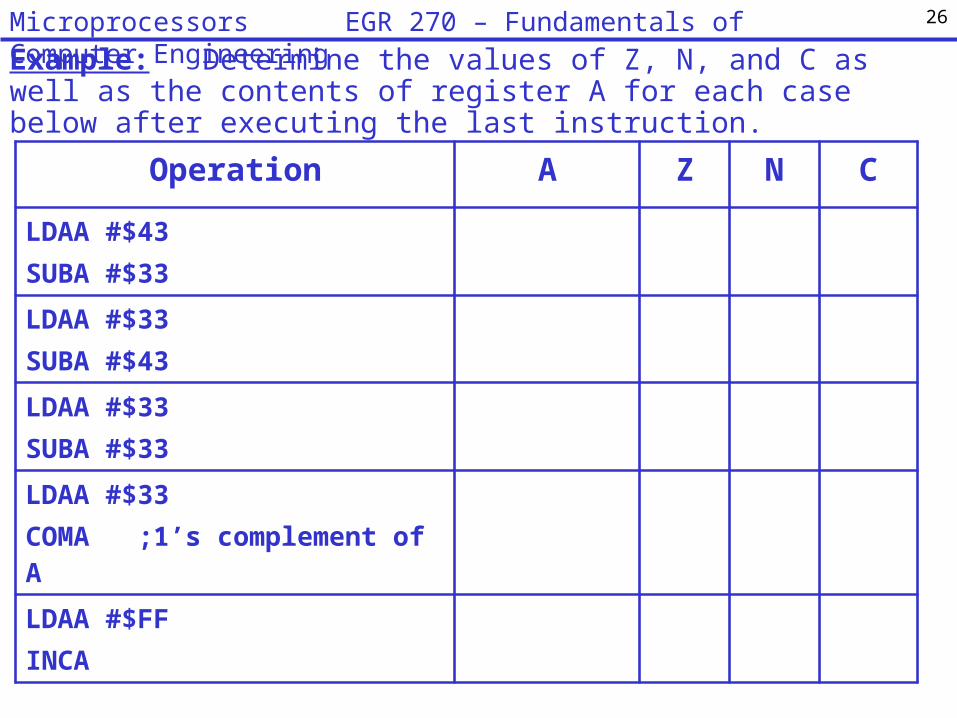
Example: Determine the values of Z, N, and C as well as the contents of register A for each case below after executing the last instruction.
Operation A Z N C
LDAA #$43SUBA #$33
LDAA #$33SUBA #$43
LDAA #$33SUBA #$33
LDAA #$33COMA ;1’s complement of A
LDAA #$FFINCA
26Microprocessors EGR 270 – Fundamentals of Computer Engineering

Instruction: BRA <label>Description: “Branch Always” - Branch always to the label indicatedExample 1: L1 BRA L1 ;infinite loopExample 2: L2 <first instruction of main loop>
<additional instructions>BRA L2 ;keep executing main loop
Instruction: BNE <label>Description: “Branch if not equal to zero” - Branch to the label indicated if Z=0 in the CCRExample: LDAA #$00 ; initialize x to 0
LDAB #$05 ; initialize y to 5L3 ABA ; add x and y, store in x
SUBB #$01 ; decrement yBNE L3 ; loop if not done
L4 BRA L4 ; all done (infinite loop)
So what are the final values in A and B in the program above?Trace (single step) through the program to see. Use the table on the following page.
27Microprocessors EGR 270 – Fundamentals of Computer Engineering
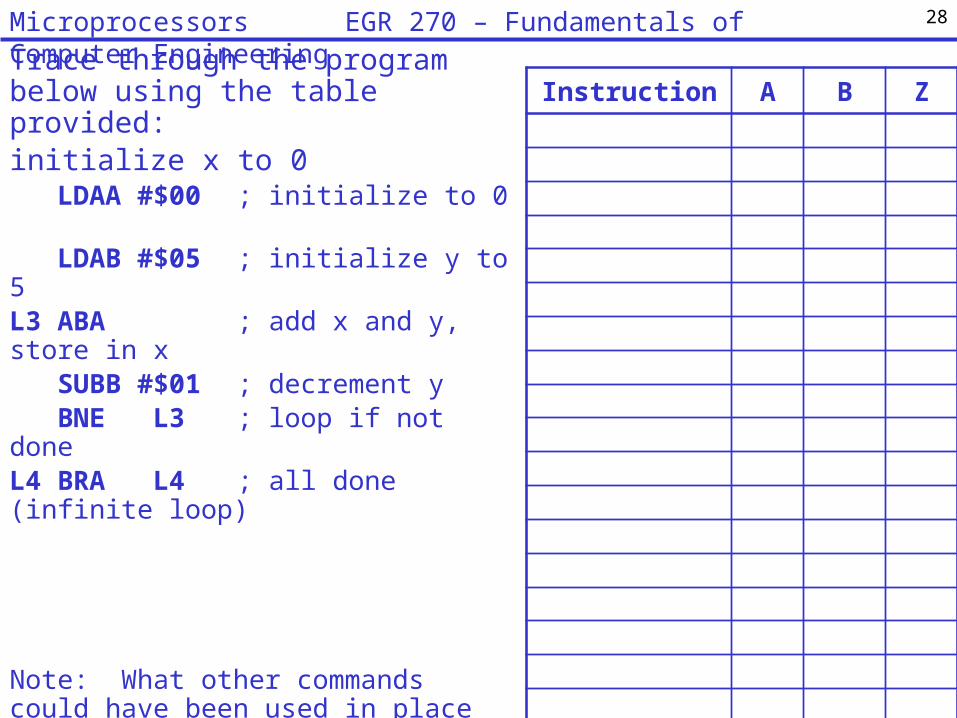
Trace through the program below using the table provided:initialize x to 0
LDAA #$00 ; initialize to 0LDAB #$05 ; initialize y to 5
L3 ABA ; add x and y, store in xSUBB #$01 ; decrement yBNE L3 ; loop if not done
L4 BRA L4 ; all done (infinite loop)
Note: What other commands could have been used in place of the commands below?1) LDAA #$00
2) SUBB #$01
Instruction A B Z
28Microprocessors EGR 270 – Fundamentals of Computer Engineering
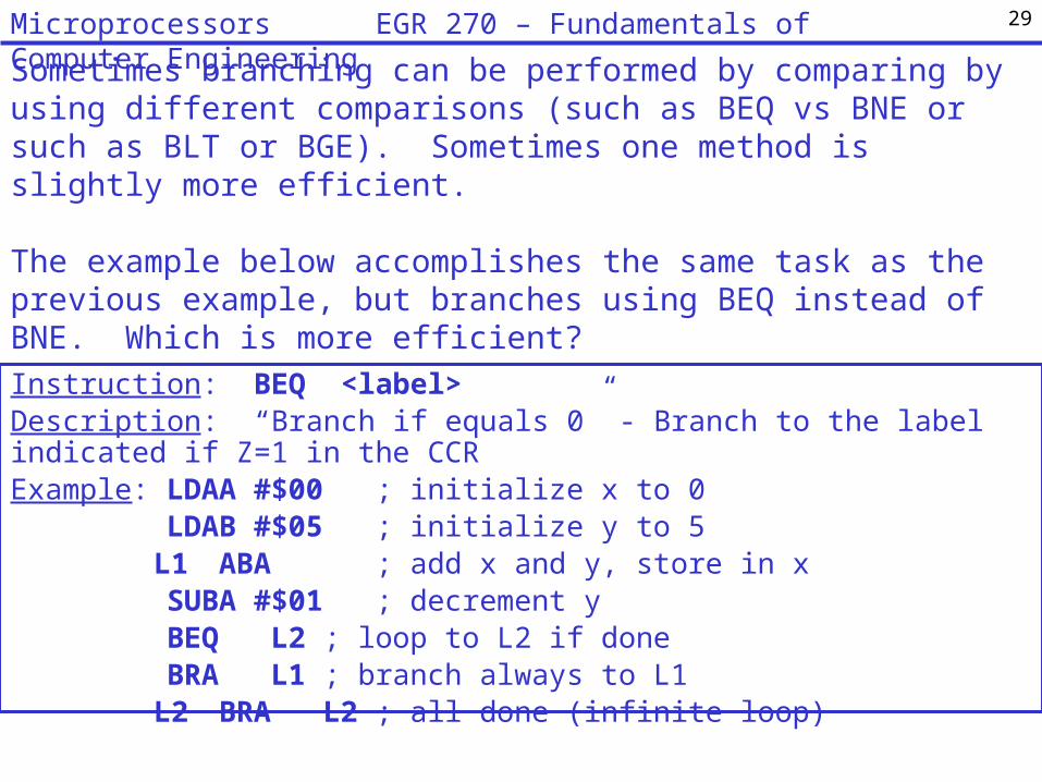
Instruction: BEQ <label>Description: “Branch if equals 0” - Branch to the label indicated if Z=1 in the CCRExample: LDAA #$00 ; initialize x to 0
LDAB #$05 ; initialize y to 5L1 ABA ; add x and y, store in x
SUBA #$01 ; decrement yBEQ L2 ; loop to L2 if doneBRA L1 ; branch always to L1
L2 BRA L2 ; all done (infinite loop)
29Microprocessors EGR 270 – Fundamentals of Computer Engineering
Sometimes branching can be performed by comparing by using different comparisons (such as BEQ vs BNE or such as BLT or BGE). Sometimes one method is slightly more efficient.
The example below accomplishes the same task as the previous example, but branches using BEQ instead of BNE. Which is more efficient?

30Microprocessors EGR 270 – Fundamentals of Computer Engineering
Instruction: CMPA aaDescription: Compare the contents of accumulator A with the contents of M[aa]. Note that the contents of A are not changed. Key result: the CCR is updated.Notation: (Update CCR) A - M[aa] Example: CMPA $05 ; (Update CCR) A - $05
BNE L1 ; Branch to L1 if the contents of A and M[aa] are not equal
Comparing a register value to memory.Sometimes it is useful to compare a register value to memory. This could be done with a subtraction operation, but then the contents of the register are changed. A compare operation, such as CMPA or CMPB, essentially performs subtraction to set the condition code register (CCR), but doesn’t change the contents of register A or B.
Other branching commands:BCC <label> ; branch to label if carry cleared, C = 0BCS <label> ; branch to label if carry set, C = 1BMI <label> ; branch to label if negative (minus), N = 1BPL <label> ; branch if positive (plus), N = 0BGT <label> ; branch if greater than zeroBGE <label> ; branch if greater than or equal to zeroBLT <label> ; branch if less than zeroBLE <label> ; branch if less than or equal to zero

Example: Form a simple loop in assembly language to perform some operation 10 times. This might be equivalent to the following in C++: for (int j = 9; j >=0; j--) { // perform operation }
31Microprocessors EGR 270 – Fundamentals of Computer Engineering

Example: Write an assembly language program to form the sum:
This could be done easily in C++ as follows: int Sum = 0;
for (int j = A; j <=B; j++) Sum += j;Assume that:• A positive value for A is stored in memory location M[$10]• A positive value for B is stored in memory location M[$11]• A < B (i.e., M[$10] < M[$11])• The result is to be stored in memory location in M[$12].
B i
A i
i Sum 39 9 8 7 6 5 4 i Sum :Example9 i
4 i
32Microprocessors EGR 270 – Fundamentals of Computer Engineering

Example: Write an assembly language program to determine the larger of two numbers. This could be done easily in C++ as follows: if (A > B) X = A; else X = B;Assume that:• A is stored in memory location M[$24]• B is stored in memory location M[$25]• The larger of the two values should be stored in M[$26].
33Microprocessors EGR 270 – Fundamentals of Computer Engineering
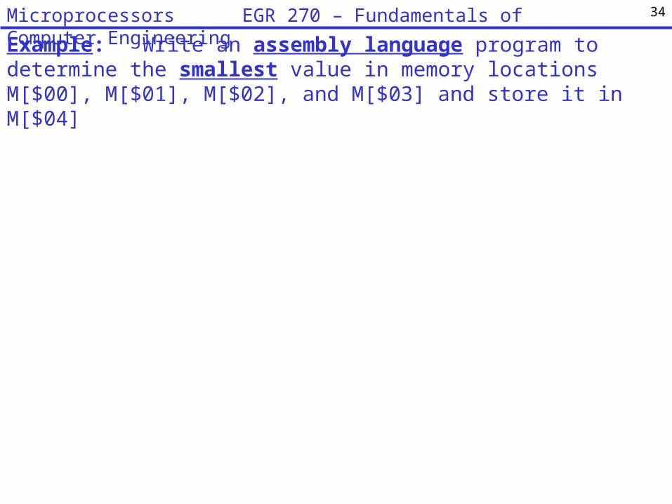
Example: Write an assembly language program to determine the smallest value in memory locations M[$00], M[$01], M[$02], and M[$03] and store it in M[$04]
34Microprocessors EGR 270 – Fundamentals of Computer Engineering
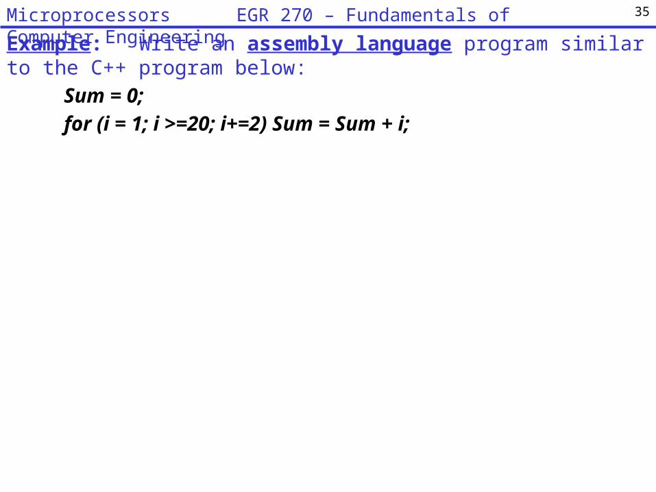
Example: Write an assembly language program similar to the C++ program below:
Sum = 0;
for (i = 1; i >=20; i+=2) Sum = Sum + i;
35Microprocessors EGR 270 – Fundamentals of Computer Engineering

Data values in 68HC11 registers.
Recall that registers A and B are 8-bit registers and that registers D, X, and Y are 16-bit registers. Since the registers contain signed binary numbers note that:
• If the MSB = 0, the value is positive• If the MSB = 1, the value is negative and in 2’s complement form
7 A 0 7 B 0
15 PC 0
15 SP 0
15 Y 0
15 X 0
15 D 0
8-Bit accumulators A and B
16-Bit double accumulator D
Index register X
Index register Y
Stack pointer
Program Counter
S X H I N Z V C Condition Code Register
36Microprocessors EGR 270 – Fundamentals of Computer Engineering
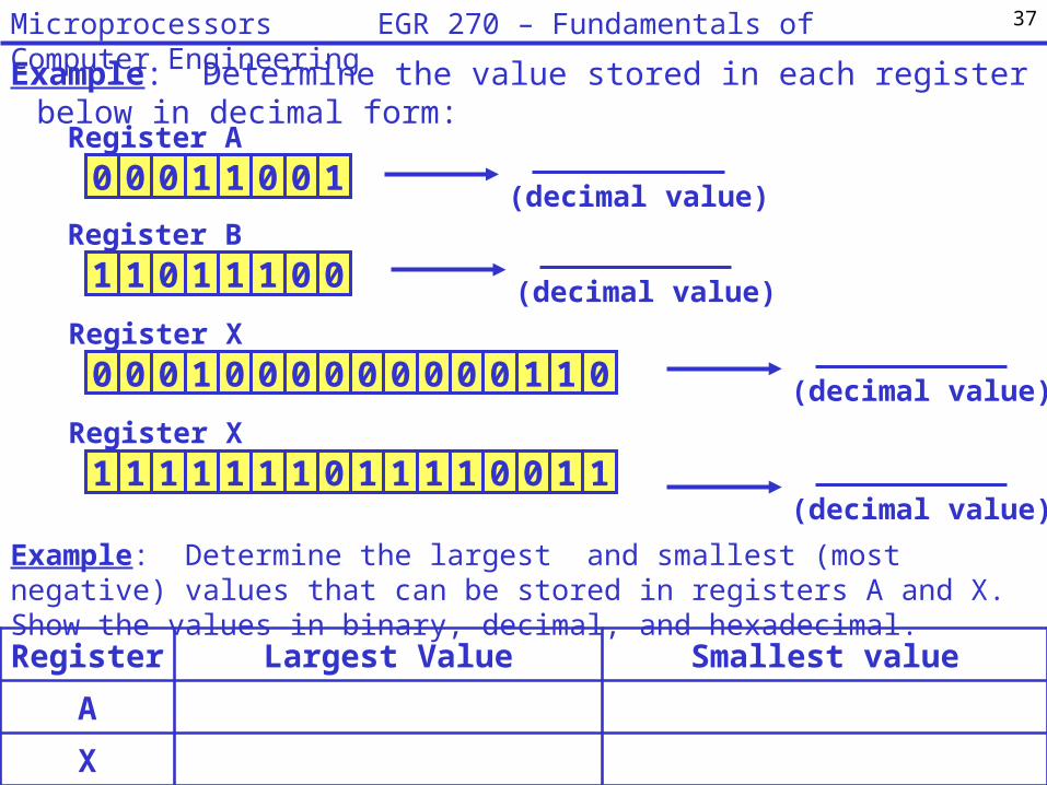
Example: Determine the value stored in each register below in decimal form:
0 0 0 1 1 0 0 1Register A
(decimal value)
1 1 0 1 1 1 0 0Register B
(decimal value)
(decimal value)0 0 0 1 0 0 0 0Register X
0 0 0 0 0 1 1 0
(decimal value)1 1 1 1 1 1 1 0Register X
1 1 1 1 0 0 1 1
Example: Determine the largest and smallest (most negative) values that can be stored in registers A and X. Show the values in binary, decimal, and hexadecimal.
Register Largest Value Smallest value
A
X
37Microprocessors EGR 270 – Fundamentals of Computer Engineering

Memory Addresses in 68HC11 registers.
Note that memory addresses are NOT signed binary numbers so no sign bit is used.
Example:
So if an 8-bit memory address is specified (2 hexadecimal digits) as in the examples below, what is the largest and smallest memory address?
STAA $00 memory address = ___________ (decimal form)
STAA $FF memory address = ___________ (decimal form)
total amount of memory addresses with 8 bits: ____________
Example:
So if an 16-bit memory address is specified (4 hexadecimal digits) as in the examples below, what is the largest and smallest memory address?
STAA $0000 memory address = ___________ (decimal form)
STAA $FFFF memory address = ___________ (decimal form)
total amount of memory addresses with 16 bits: __________
38Microprocessors EGR 270 – Fundamentals of Computer Engineering
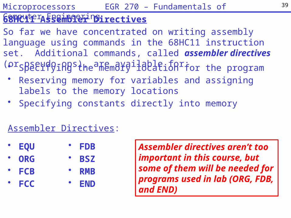
68HC11 Assembler Directives
So far we have concentrated on writing assembly language using commands in the 68HC11 instruction set. Additional commands, called assembler directives (or pseudo-ops), are available for:
• Specifying the memory location for the program• Reserving memory for variables and assigning labels to the memory
locations• Specifying constants directly into memory
Assembler Directives:
• EQU• ORG• FCB• FCC
• FDB• BSZ• RMB• END
39Microprocessors EGR 270 – Fundamentals of Computer Engineering
Assembler directives aren’t too important in this course, but some of them will be needed for programs used in lab (ORG, FDB, and END)

ORG <expression>Directs the assembler to set an address. Any code or data following an ORG will begin at the specified address.Example:ORG $8000 ;Store the following program at this location in ROMLDAA #$FF ;First line of program
<label> EQU <expression>Directs the assembler to substitute the expression value where the label appearsExample:Amount EQU $40 ;Equate the label Amount to memory address M[$40]…STAA Amount ;Store value in memory location labeled Amount
(<label>) FCB <expr> (,<expr>,…,<expr>)Form Constant Byte - 8 bit constantsDirects the assembler to store each value listed as an 8-bit constant in successive memory locationsExample:ORG $0050Fibonacci FCB 0, 1, 1, 2, 3, 5, 8, 13; ;Store constants beginning at M[$0050]
40Microprocessors EGR 270 – Fundamentals of Computer Engineering

(<label>) FDB <expr>(,<expr>,…,<expr>)
Form Double Byte - 16 bit constantsDirects the assembler to store each value listed as an 16-bit constant in successive
memory locationsExample:ORG $0040
Mask FDB %1000100110101011 ;Store binary value at M[$0040]
Data FDB 4000, 6000, 8000 ;Store 16-bit constants beginning at M[$0042]
(<label>) FCC 'String'
Form Character Constant - Character StringDirects the assembler to store the ASCII values in successive memory locations.Example:ORG $0050
Message FCC 'Hello World!‘ ;Store ASCII Code for H at M[$0050] and
;remaining ASCII codes in successive bytes
41Microprocessors EGR 270 – Fundamentals of Computer Engineering
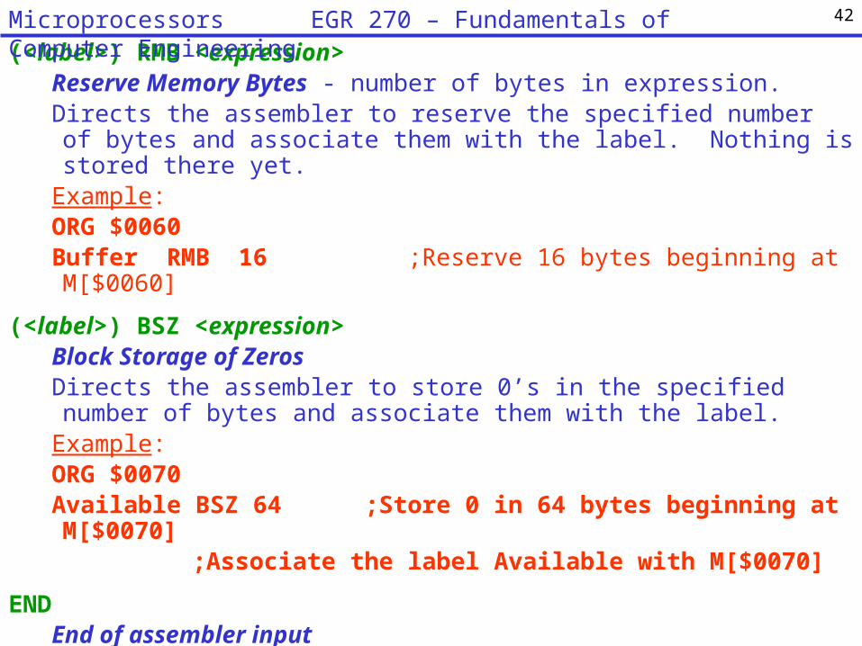
(<label>) RMB <expression>Reserve Memory Bytes - number of bytes in expression. Directs the assembler to reserve the specified number of bytes and associate them with the label. Nothing is stored there yet.
Example:ORG $0060Buffer RMB 16 ;Reserve 16 bytes beginning at M[$0060]
(<label>) BSZ <expression>Block Storage of ZerosDirects the assembler to store 0’s in the specified number of bytes and associate them with the label.
Example:ORG $0070Available BSZ 64 ;Store 0 in 64 bytes beginning at M[$0070]
;Associate the label Available with M[$0070]
ENDEnd of assembler inputDirects the assembler to stop reading the file. All lines following END are comments. If END is omitted, the assembler reads until the end of file.
42Microprocessors EGR 270 – Fundamentals of Computer Engineering

MemoryWhen working with microcontrollers and their limited memory, it is important to be aware what memory addresses are available for:
• 68HC11 registers• Storing data• Storing programs
A memory map is often used to illustrate different sections of memory. Different microcontrollers have different amounts of memory. Note that some memory addresses are used to access RAM and others are used to access ROM.RAM (Random Access Memory)• Used for temporary storage of program data and register contents• This information is lost when power is turned off to the MicroStamp11• Most MicroStamp11’s have only 256 bytes of RAM, although some versions offer
additional RAM.ROM (Read-Only Memory) or EEPROM (Electrically Erasable Programmable ROM)• Used to store programs (i.e., S19 files that are downloaded).• This information is NOT lost when power is turned off to the MicroStamp11• The MicroStamp11 is available with 8kB, 32kB, or 64kB of EEPROM. The
MicroStamp11’s to be used in lab have 32kB of EEPROM.
43Microprocessors EGR 270 – Fundamentals of Computer Engineering
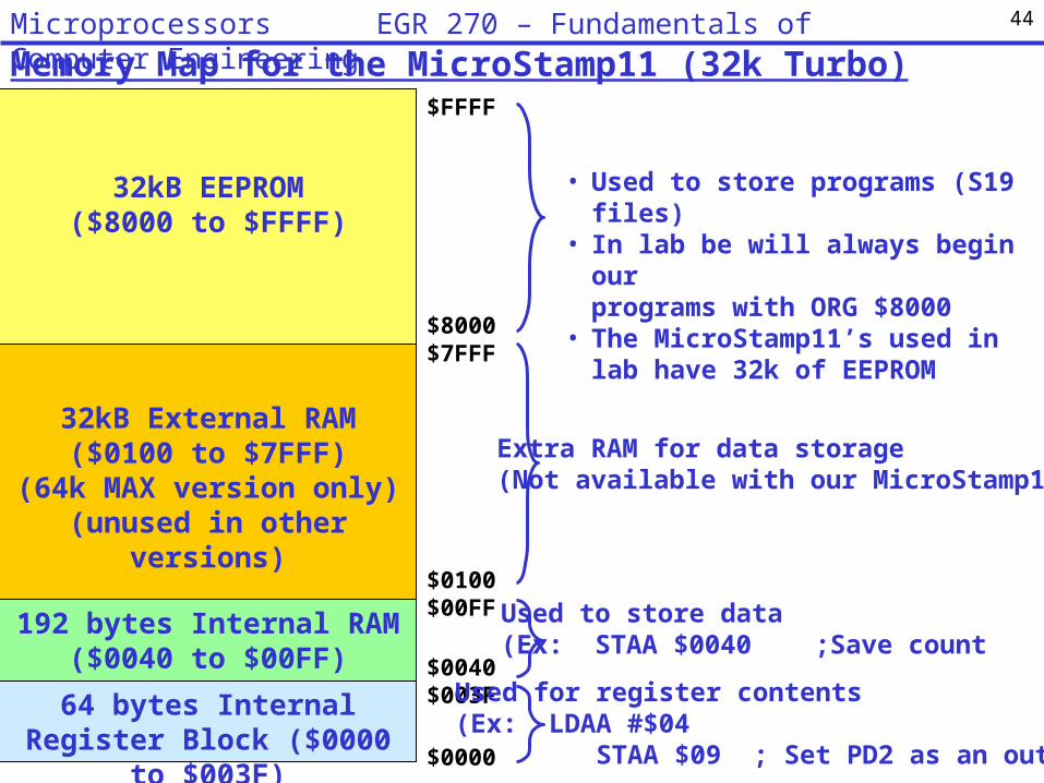
Memory Map for the MicroStamp11 (32k Turbo)
32kB EEPROM($8000 to $FFFF)
32kB External RAM($0100 to $7FFF)
(64k MAX version only)(unused in other versions)
192 bytes Internal RAM($0040 to $00FF)
64 bytes Internal Register Block ($0000 to $003F)
$FFFF
$8000$7FFF
$0100$00FF
$0040$003F
$0000
• Used to store programs (S19 files)• In lab be will always begin our
programs with ORG $8000• The MicroStamp11’s used in lab have
32k of EEPROM
Extra RAM for data storage(Not available with our MicroStamp11)
Used to store data(Ex: STAA $0040 ;Save count
Used for register contents(Ex: LDAA #$04 STAA $09 ; Set PD2 as an output)
44Microprocessors EGR 270 – Fundamentals of Computer Engineering

Compiler Directives – use in lab
Example program from the lecture for Lab 8
Don’t worry about the details now, but note that the program uses two compiler directives: ORG and FDB.
45Microprocessors EGR 270 – Fundamentals of Computer Engineering

Assemblers
An assembler converts assembly language instructions into machine code.• Most assemblers are “2-pass” assemblers, where the assembler essentially
converts mnemonics into op codes on the first pass and then determines offsets for branches, memory locations, etc., on the second pass.
• The assembler often produces two key files: the executable machine code (.S19 file) and a listing file (.LST) which shows the program listing with op codes and computed offsets.
Assembler
Assemblylanguageprogram
(Ex1.asm)
List File(Ex1.lst)
MachineCode
(Ex1.s19)
46Microprocessors EGR 270 – Fundamentals of Computer Engineering

Simulators
Simulators are used to test assembly language programs. Simulators can be used to step through programs, check memory and register contents, etc. It is always a good idea to simulate a program if possible before downloading it into a microcontroller.
Assemblers and Simulators used in this course
In this course we will use two freeware programs to assemble and simulate programs: MGTEK MiniIDE – Windows 68HC11 assembler Wookie – Windows 68HC11 simulator
Refer to the following handout available on the instructor’s webpage:
“Example: Mini IDE Assembler and Wookie Simulator”
47Microprocessors EGR 270 – Fundamentals of Computer Engineering