MICROPROCESSOR & MICROCONTROLLER - KTU B …ktubtechquestions.com/wp-content/uploads/2017/08/... ·...
45
MICROPROCESSOR & MICROCONTROLLER MODULE I Evolution of Microprocessor 4-bit Microprocessors The first microprocessor was introduced in 1971 by Intel Corp. It was named Intel 4004 as it was a 4 bit processor. It was a processor on a single chip. It could perform simple arithmetic and logic operations such as addition, subtraction, boolean AND and boolean OR. It had a control unit capable of performing control functions like fetching an instruction from memory, decoding it, and generating control pulses to execute it. It was able to operate on 4 bits of data at a time.This first microprocessor was quite a success in industry. Soon other microprocessors were also introduced. Intel introduced the enhanced version of 4004, the 4040. Some other 4 bit processors are International’s PPS4 and Thoshiba’s T3472. 8-bit Microprocessors The first 8 bit microprocessor which could perform arithmetic and logic operations on 8 bit words was introduced in 1973 again by Intel. This was Intel 8008 and was later followed by an improved version, Intel 8088. Some other 8 bit processors are Zilog- 80 and Motorola M6800. 16-bit Microprocessors The 8-bit processors were followed by 16 bit processors. They are Intel 8086 and 80286. 32-bit Microprocessors The 32 bit microprocessors were introduced by several companies but the most popular one is Intel 80386. Pentium Series Instead of 80586, Intel came out with a new processor namely Pentium processor. Its performance is closer to RISC performance. Pentium was followed by Pentium Pro CPU. Pentium Pro allows allow multiple CPUs in a single system in order to achive
Transcript of MICROPROCESSOR & MICROCONTROLLER - KTU B …ktubtechquestions.com/wp-content/uploads/2017/08/... ·...

MICROPROCESSOR & MICROCONTROLLER
MODULE I
Evolution of Microprocessor
4-bit Microprocessors
The first microprocessor was introduced in 1971 by Intel Corp. It was named Intel
4004 as it was a 4 bit processor. It was a processor on a single chip. It could perform
simple arithmetic and logic operations such as addition, subtraction, boolean AND
and boolean OR. It had a control unit capable of performing control functions like
fetching an instruction from memory, decoding it, and generating control pulses to
execute it. It was able to operate on 4 bits of data at a time.This
first microprocessor was quite a success in industry. Soon other microprocessors were
also introduced. Intel introduced the enhanced version of 4004, the 4040. Some other
4 bit processors are International’s PPS4 and Thoshiba’s T3472.
8-bit Microprocessors
The first 8 bit microprocessor which could perform arithmetic and logic operations on
8 bit words was introduced in 1973 again by Intel. This was Intel 8008 and was later
followed by an improved version, Intel 8088. Some other 8 bit processors are Zilog-
80 and Motorola M6800.
16-bit Microprocessors
The 8-bit processors were followed by 16 bit processors. They are Intel 8086 and
80286.
32-bit Microprocessors
The 32 bit microprocessors were introduced by several companies but the most
popular one is Intel 80386.
Pentium Series
Instead of 80586, Intel came out with a new processor namely Pentium processor. Its
performance is closer to RISC performance. Pentium was followed by Pentium Pro
CPU. Pentium Pro allows allow multiple CPUs in a single system in order to achive

multiprocessing. The MMX extension was added to Pentium Pro and the result was
Pentiuum II. The low cost version of Pentium II is celeron.
The Pentium III provided high performance floating point operations for certain types
of computations by using the SIMD extensions to the instruction set. These new
instructions makes the Pentium III faster than high-end RISC CPUs.
Interestingly Pentium IV could not execute code faster than the Pentium III when
running at the same clock frequency. So Pentium IV had to speed up by executing at a
much higher clock frequency.
8086 Microprocessor - Architecture and signals
8086 Microprocessor is an enhanced version of 8085Microprocessor that
was designed by Intel in 1976. It is a 16-bit Microprocessor having 20
address lines and16 data lines that provides up to 1MB storage. It consists
of powerful instruction set, which provides operations like multiplication and
division easily.
It supports two modes of operation, i.e. Maximum mode and Minimum
mode. Maximum mode is suitable for system having multiple processors
and Minimum mode is suitable for system having a single processor.
Features of 8086 The most prominent features of a 8086 microprocessor are as follows −
It has an instruction queue, which is capable of storing six instruction
bytes from the memory resulting in faster processing.
It was the first 16-bit processor having 16-bit ALU, 16-bit registers,
internal data bus, and 16-bit external data bus resulting in faster
processing.
It is available in 3 versions based on the frequency of operation −
o 8086 → 5MHz

o 8086-2 → 8MHz
o (c)8086-1 → 10 MHz
It uses two stages of pipelining, i.e. Fetch Stage and Execute Stage,
which improves performance.
Fetch stage can prefetch up to 6 bytes of instructions and stores them in
the queue.
Execute stage executes these instructions.
It has 256 vectored interrupts.
It consists of 29,000 transistors.
Comparison between 8085 & 8086
Microprocessor Size − 8085 is 8-bit microprocessor, whereas 8086 is 16-bit
microprocessor.
Address Bus − 8085 has 16-bit address bus while 8086 has 20-bit
address bus.
Memory − 8085 can access up to 64Kb, whereas 8086 can access up to
1 Mb of memory.
Instruction − 8085 doesn’t have an instruction queue, whereas 8086
has an instruction queue.
Pipelining − 8085 doesn’t support a pipelined architecture while 8086
supports a pipelined architecture.
I/O − 8085 can address 2^8 = 256 I/O's, whereas 8086 can access
2^16 = 65,536 I/O's.
Cost − The cost of 8085 is low whereas that of 8086 is high.
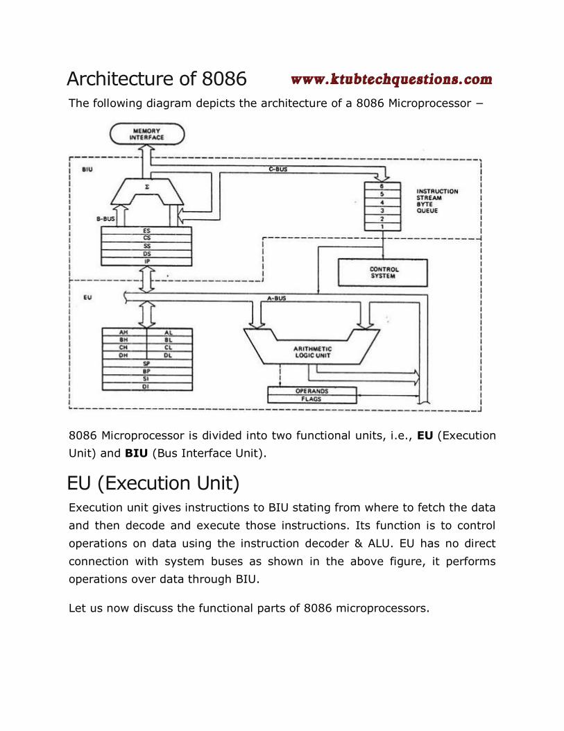
Architecture of 8086 The following diagram depicts the architecture of a 8086 Microprocessor −
8086 Microprocessor is divided into two functional units, i.e., EU (Execution
Unit) and BIU (Bus Interface Unit).
EU (Execution Unit) Execution unit gives instructions to BIU stating from where to fetch the data
and then decode and execute those instructions. Its function is to control
operations on data using the instruction decoder & ALU. EU has no direct
connection with system buses as shown in the above figure, it performs
operations over data through BIU.
Let us now discuss the functional parts of 8086 microprocessors.

ALU
It handles all arithmetic and logical operations, like +, −, ×, /, OR, AND,
NOT operations.
Flag Register
It is a 16-bit register that behaves like a flip-flop, i.e. it changes its status
according to the result stored in the accumulator. It has 9 flags and they
are divided into 2 groups − Conditional Flags and Control Flags.
Conditional Flags
It represents the result of the last arithmetic or logical instruction executed.
Following is the list of conditional flags −
Carry flag − This flag indicates an overflow condition for arithmetic
operations.
Auxiliary flag − When an operation is performed at ALU, it results in a
carry/barrow from lower nibble (i.e. D0 – D3) to upper nibble (i.e. D4 –
D7), then this flag is set, i.e. carry given by D3 bit to D4 is AF flag. The
processor uses this flag to perform binary to BCD conversion.
Parity flag − This flag is used to indicate the parity of the result, i.e.
when the lower order 8-bits of the result contains even number of 1’s,
then the Parity Flag is set. For odd number of 1’s, the Parity Flag is
reset.
Zero flag − This flag is set to 1 when the result of arithmetic or logical
operation is zero else it is set to 0.
Sign flag − This flag holds the sign of the result, i.e. when the result of
the operation is negative, then the sign flag is set to 1 else set to 0.
Overflow flag − This flag represents the result when the system
capacity is exceeded.

Control Flags
Control flags controls the operations of the execution unit. Following is the
list of control flags −
Trap flag − It is used for single step control and allows the user to
execute one instruction at a time for debugging. If it is set, then the
program can be run in a single step mode.
Interrupt flag − It is an interrupt enable/disable flag, i.e. used to
allow/prohibit the interruption of a program. It is set to 1 for interrupt
enabled condition and set to 0 for interrupt disabled condition.
Direction flag − It is used in string operation. As the name suggests
when it is set then string bytes are accessed from the higher memory
address to the lower memory address and vice-a-versa.
General purpose register
There are 8 general purpose registers, i.e., AH, AL, BH, BL, CH, CL, DH, and
DL. These registers can be used individually to store 8-bit data and can be
used in pairs to store 16bit data. The valid register pairs are AH and AL, BH
and BL, CH and CL, and DH and DL. It is referred to the AX, BX, CX, and DX
respectively.
AX register − It is also known as accumulator register. It is used to
store operands for arithmetic operations.
BX register − It is used as a base register. It is used to store the
starting base address of the memory area within the data segment.
CX register − It is referred to as counter. It is used in loop instruction to
store the loop counter.
DX register − This register is used to hold I/O port address for I/O
instruction.
Stack pointer register
It is a 16-bit register, which holds the address from the start of the
segment to the memory location, where a word was most recently stored
on the stack.
BIU (Bus Interface Unit) BIU takes care of all data and addresses transfers on the buses for the EU
like sending addresses, fetching instructions from the memory, reading data
from the ports and the memory as well as writing data to the ports and the
memory. EU has no direction connection with System Buses so this is
possible with the BIU. EU and BIU are connected with the Internal Bus.
It has the following functional parts −
Instruction queue − BIU contains the instruction queue. BIU gets upto
6 bytes of next instructions and stores them in the instruction queue.
When EU executes instructions and is ready for its next instruction, then
it simply reads the instruction from this instruction queue resulting in
increased execution speed.
Fetching the next instruction while the current instruction executes is
called pipelining.
Segment register − BIU has 4 segment buses, i.e. CS, DS, SS& ES. It
holds the addresses of instructions and data in memory, which are used
by the processor to access memory locations. It also contains 1 pointer
register IP, which holds the address of the next instruction to executed
by the EU.
o CS − It stands for Code Segment. It is used for addressing a
memory location in the code segment of the memory, where the
executable program is stored.

o DS − It stands for Data Segment. It consists of data used by the
program andis accessed in the data segment by an offset address
or the content of other register that holds the offset address.
o SS − It stands for Stack Segment. It handles memory to store
data and addresses during execution.
o ES − It stands for Extra Segment. ES is additional data segment,
which is used by the string to hold the extra destination data.
Instruction pointer − It is a 16-bit register used to hold the address of
the next instruction to be executed.
Memory organisation
As far as we know 8086 is 16-bit processor that can supports 1Mbyte (i.e. 20-bit address bus: 220) of external memory over the address range 0000016 to FFFFF16. The 8086 organizes memory as individual bytes of data. The 8086 can access any two consecutive bytes as a word of data. The lower-addressed byte is the least significant byte of the word, and the higher- addressed byte is its most significant byte.
Figure: Part of 1 Mbyte Memory The above figure represents: storage location of address 0000916 contains the value 716, while the location of address 0001016 contains the value 7D16. The 16-bit word 225A16is stored in the locations 0000C16 to 0000D16 The word of data is at an even-address boundary (i.e. address of least significant byte is even) is called aligned word. The word of data is at an odd-address boundary is called misaligned word, as shown in Figure below.
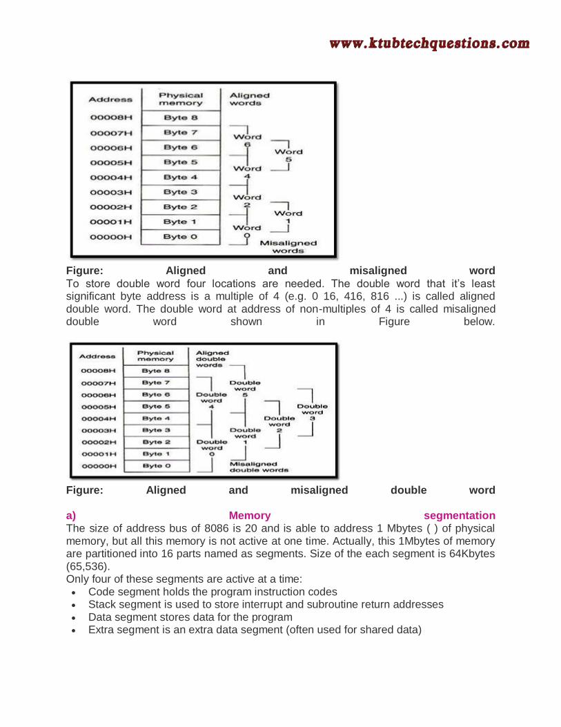
Figure: Aligned and misaligned word
To store double word four locations are needed. The double word that it’s least significant byte address is a multiple of 4 (e.g. 0 16, 416, 816 ...) is called aligned double word. The double word at address of non-multiples of 4 is called misaligned double word shown in Figure below.
Figure: Aligned and misaligned double word a) Memory segmentation The size of address bus of 8086 is 20 and is able to address 1 Mbytes ( ) of physical memory, but all this memory is not active at one time. Actually, this 1Mbytes of memory are partitioned into 16 parts named as segments. Size of the each segment is 64Kbytes (65,536). Only four of these segments are active at a time: Code segment holds the program instruction codes Stack segment is used to store interrupt and subroutine return addresses Data segment stores data for the program Extra segment is an extra data segment (often used for shared data)

Each of these segments are addressed by an address stored in corresponding segment registers: CS(code segment), SS(stack segment), DS(data segment), and ES(extra segment). These registers contain a 16-bit base address that points to the lowest addressed byte of the segment. Because the segment registers cannot store 20 bits, they only store the upper 16 bits. The BIU takes care of this problem by appending four 0's to the low-order bits of the segment register. In effect, this multiplies the segment register contents by 16.
The segment registers are user accessible, which means that the programmer can change the content of segment registers through software. b) Programming model:
How can a 20-bit address be obtained, if there are only 16-bit registers? However, the largest register is only 16 bits (64k); so physical addresses have to be calculated. These calculations are done in hardware within the microprocessor. The 16-bit contents of segment register gives the starting/ base address of particular segment. To address a specific memory location within a segment we need an offset address. The offset address is also 16-bit wide and it is provided by one of the associated pointer or index register.

Figure: Software model of 8086 microprocessor
To be able to program a microprocessor, one does not need to know all of its hardware architectural features. What is important to the programmer is being aware of the various registers within the device and to understand their purpose, functions, operating capabilities, and limitations. The above figure illustrates the software architecture of the 8086 microprocessor. From this diagram, we see that it includes fourteenl6-bit internal registers: the instruction pointer (IP), four data registers (AX, BX, CX, and DX), two pointer registers (BP and SP), two index registers (SI and DI), four segment registers (CS, DS, SS, and ES) and status register (SR), with nine of its bits implemented as status and control flags. The point to note is that the beginning segment address must begin at an address divisible by 16.Also note that the four segments need not be defined separately. It is allowable for all four segments to completely overlap (CS = DS = ES = SS). c) Logical and Physical Address
Addresses within a segment can range from address 00000h to address 0FFFFh. This corresponds to the 64K-bytelength of the segment. An address within a segment is called an offset or logical address. A logical address gives the displacement from the base address of the segment to the desired location within it, as opposed to its "real" address, which maps directly anywhere into the 1 MByte memory space. This "real" address is called the physical address. What is the difference between the physical and the logical address? The physical address is 20 bits long and corresponds to the actual binary code output by the BIU on the address bus lines. The logical address is an offset from location 0 of a
given segment.
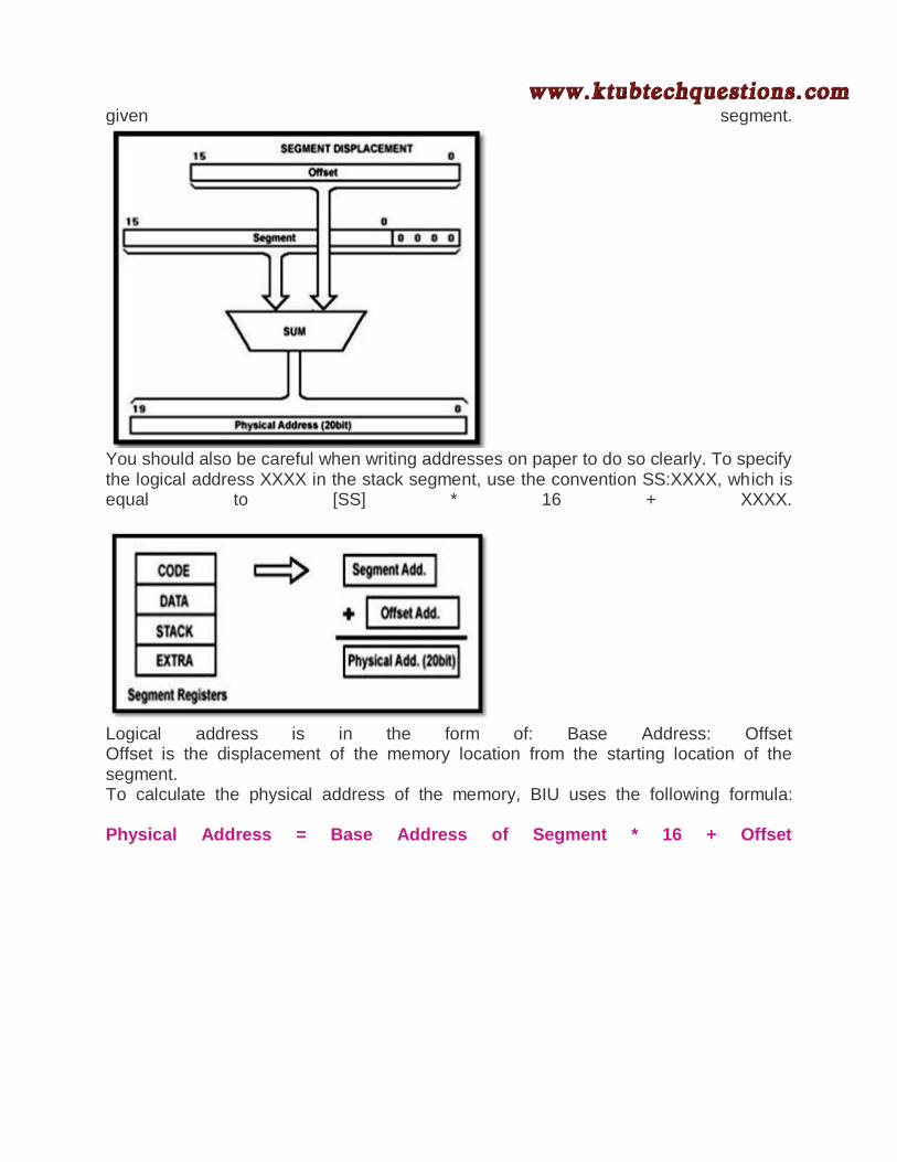
You should also be careful when writing addresses on paper to do so clearly. To specify the logical address XXXX in the stack segment, use the convention SS:XXXX, which is equal to [SS] * 16 + XXXX.
Logical address is in the form of: Base Address: Offset Offset is the displacement of the memory location from the starting location of the segment. To calculate the physical address of the memory, BIU uses the following formula: Physical Address = Base Address of Segment * 16 + Offset

Example: The value of Data Segment Register (DS) is 2222H. To convert this 16-bit address into 20-bit, the BIU appends 0H to the LSB (by multiplying with 16) of the address. After appending, the starting address of the Data Segment becomes 22220H. Data at any location has a logical address specified as:2222H: 0016H Where 0016H is the offset, 2222 H is the value of DS Therefore the physical address:22220H + 0016H : 22236 H
The following tables describes the default offset values to the corresponding memory segments.
Some of the advantages of memory segmentation in the 8086 are as follows: With the help of memory segmentation a user is able to work with registers having
only 16-bits. The data and the user’s code can be stored separately allowing for more flexibility. Also due to segmentation the logical address range is from 0000H to FFFFH the
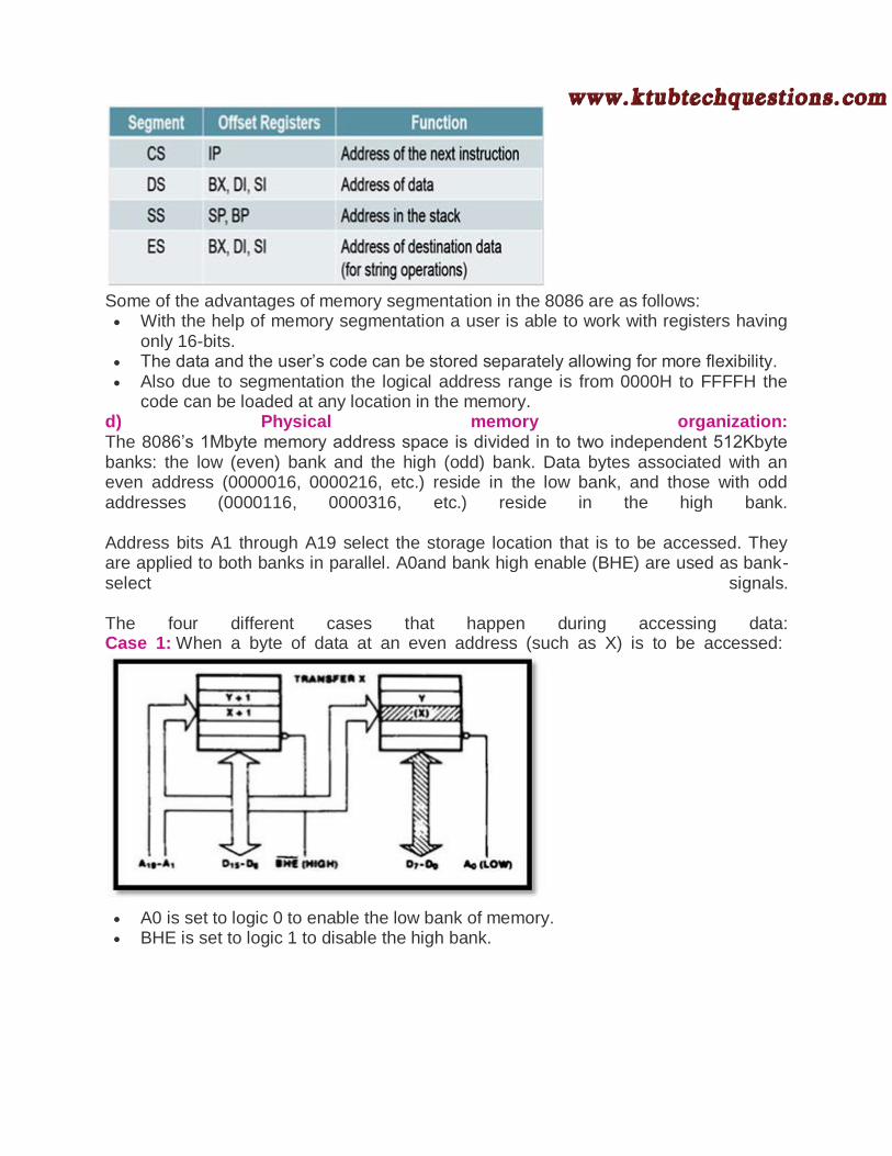
code can be loaded at any location in the memory. d) Physical memory organization: The 8086’s 1Mbyte memory address space is divided in to two independent 512Kbyte banks: the low (even) bank and the high (odd) bank. Data bytes associated with an even address (0000016, 0000216, etc.) reside in the low bank, and those with odd addresses (0000116, 0000316, etc.) reside in the high bank. Address bits A1 through A19 select the storage location that is to be accessed. They are applied to both banks in parallel. A0and bank high enable (BHE) are used as bank-select signals. The four different cases that happen during accessing data: Case 1: When a byte of data at an even address (such as X) is to be accessed:
A0 is set to logic 0 to enable the low bank of memory. BHE is set to logic 1 to disable the high bank.

Case 2: When a byte of data at an odd address (such as X+1) is to be accessed:
A0is set to logic 1 to disable the low bank of memory. BHE is set to logic 0 to enable the high bank.
Case 3: When a word of data at an even address (aligned word) is to be accessed:
A0 is set to logic 0 to enable the low bank of memory. BHE is set to logic 0 to enable the high bank.
Case 4: When a word of data at an odd address (misaligned word) is to be accessed,
then the 8086 need two bus cycles to access it: a) During the first bus cycle, the odd byte of the word (in the high bank) is addressed

A0 is set to logic 1 to disable the low bank of memory BHE is set to logic 0 to enable the high bank.
b) During the second bus cycle, the odd byte of the word (in the low bank) is addressed
A0is set to logic 0 to enable the low bank of memory. BHE is set to logic 1 to disable the high bank.
Minimum and maximum mode of operation, Minimum mode
Timing Diagram.
Difference between MAX and MIN mode
Maximum mode Minimum Mode
When MN/MX(bar) low 8086 is in maximum When MN/MX(bar) high 8086 is in

mode. minimum mode.
In maximum mode 8086 generates
QS1,QS0,S0(bar),S1(bar),S2(bar),
LOCK(bar),RQ(bar)/GT1,RQ(bar)/GT0
control signals.
In minimum mode 8086 generates
INTA(bar), ALE, DEN(bar),
DT/R(bar), M/IO(bar),
HLDA,HOLD and WR(bar) control
signals.
So clearly there are multiple processors in
the system.
There is only one processor in the
system minimum mode.
Whereas in maximum mode interfacing,
master/slave and multiplexing and several
such control signals are requiredIn
maximum mode a bus controller is required
to produce control signals. This bus
controller produces MEMRDC, MEMWRC,
IORDC, IOWRC, ALE, DEN, DT/R control
signals.
In minimum mode no interfacing
or master/slave signals is
required.In minimum mode direct
RD WR signals can be used. No
bus controller required. A simple
demultiplexer would do the job. of
producing the control signals. This
demultiplexer produces MEMRD,
MEMWR, IORD, IOWR control
signals.
TIMING DIAGRAM of MINIMUM MODE 8086
The HOLD pin is checked at the end of each bus cycle.
If it is received active by the processor before T4 of the
previous cycle of during T1 state of the current cycles, the CPU
activates HLDA in the next clock cycle and for the succeeding
bus cycles; the bus will be given to another requesting master.

The control of the bus is not regained by the processor until
the requesting master does not drop the HLDA pin low.
When the request is dropped by the requesting master, the HLDA
is dropped by the processor at the trailing edge of the next
clock, as shown in Fig

The other conditions have already been discussed in the signal
description section for the HOLD and HLDA signals.
Comparison of 8086 and 8088
8086 8088
The instruction Queue is 6 byte long. The instruction Queue is 4 byte long.
In 8086, memory divides into two banks
-even or lower bank
-odd or higher bank
The memory in 8088 does not divide into two
banks.
The data bus of 8086 is 16-bit wide The data bus of 8088 is 8-bit wide.
It has BHE (bar) signal on pin no. 34 & there is no
SSO (bar) signal.
It does not have BHE (bar) signal on pin no. 34 &
has only SSO (bar) signal. It has no S7 pin.
Control pin in 8086 is M/IO (bar). Control pin in 8088 is IO/M (bar).
It needs one machine cycle to R/W signal if it is at
even location otherwise it needs two. It needs one machine cycle to R/W signal if it is at
even location otherwise it needs two.
In 8086, all address & data Buses are multiplexed. In 8088, address bus; AD7- AD0 buses are
multiplexed.

It needs two IC 74343 for de-multiplexing AD0-
AD19. It needs one IC 74343 for de-multiplexing AD0-AD7.
Maximum supply current 360mA. Maximum supply current 340mA.
Three clock speed: 5, 8, 10 MHz Two clock speed: 5, 8 MHz
MODULE II
addressing modes
The different ways in which a source operand is denoted in an instruction is
known as addressing modes. There are 8 different addressing modes in
8086 programming −
Immediate addressing mode The addressing mode in which the data operand is a part of the instruction
itself is known as immediate addressing mode.
Example
MOV CX, 4929 H, ADD AX, 2387 H, MOV AL, FFH
Register addressing mode It means that the register is the source of an operand for an instruction.
Example
MOV CX, AX ; copies the contents of the 16-bit AX register into ; the 16-bit CX register), ADD BX, AX
Direct addressing mode The addressing mode in which the effective address of the memory location
is written directly in the instruction.
Example
MOV AX, [1592H], MOV AL, [0300H]

Register indirect addressing mode This addressing mode allows data to be addressed at any memory location
through an offset address held in any of the following registers: BP, BX, DI
& SI.
Example
MOV AX, [BX] ; Suppose the register BX contains 4895H, then the contents ; 4895H are moved to AX ADD CX, {BX}
Based addressing mode In this addressing mode, the offset address of the operand is given by the
sum of contents of the BX/BP registers and 8-bit/16-bit displacement.
Example
MOV DX, [BX+04], ADD CL, [BX+08]
Indexed addressing mode In this addressing mode, the operands offset address is found by adding the
contents of SI or DI register and 8-bit/16-bit displacements.
Example
MOV BX, [SI+16], ADD AL, [DI+16]
Based-index addressing mode In this addressing mode, the offset address of the operand is computed by
summing the base register to the contents of an Index register.
Example
ADD CX, [AX+SI], MOV AX, [AX+DI]
Based indexed with displacement mode In this addressing mode, the operands offset is computed by adding the
base register contents. An Index registers contents and 8 or 16-bit
displacement.

Example
MOV AX, [BX+DI+08], ADD CX, [BX+SI+16]
8086 Instruction set
The 8086 microprocessor supports 8 types of instructions −
Data Transfer Instructions
Arithmetic Instructions
Bit Manipulation Instructions
String Instructions
Program Execution Transfer Instructions (Branch & Loop Instructions)
Processor Control Instructions
Iteration Control Instructions
Interrupt Instructions
Let us now discuss these instruction sets in detail.
Data Transfer Instructions These instructions are used to transfer the data from the source operand to
the destination operand. Following are the list of instructions under this
group −
Instruction to transfer a word
MOV − Used to copy the byte or word from the provided source to the
provided destination.
PPUSH − Used to put a word at the top of the stack.
POP − Used to get a word from the top of the stack to the provided
location.

PUSHA − Used to put all the registers into the stack.
POPA − Used to get words from the stack to all registers.
XCHG − Used to exchange the data from two locations.
XLAT − Used to translate a byte in AL using a table in the memory.
Instructions for input and output port transfer
IN − Used to read a byte or word from the provided port to the
accumulator.
OUT − Used to send out a byte or word from the accumulator to the
provided port.
Instructions to transfer the address
LEA − Used to load the address of operand into the provided register.
LDS − Used to load DS register and other provided register from the
memory
LES − Used to load ES register and other provided register from the
memory.
Instructions to transfer flag registers
LAHF − Used to load AH with the low byte of the flag register.
SAHF − Used to store AH register to low byte of the flag register.
PUSHF − Used to copy the flag register at the top of the stack.
POPF − Used to copy a word at the top of the stack to the flag register.
Arithmetic Instructions These instructions are used to perform arithmetic operations like addition,
subtraction, multiplication, division, etc.
Following is the list of instructions under this group −
Instructions to perform addition
ADD − Used to add the provided byte to byte/word to word.
ADC − Used to add with carry.
INC − Used to increment the provided byte/word by 1.
AAA − Used to adjust ASCII after addition.
DAA − Used to adjust the decimal after the addition/subtraction
operation.
Instructions to perform subtraction
SUB − Used to subtract the byte from byte/word from word.
SBB − Used to perform subtraction with borrow.
DEC − Used to decrement the provided byte/word by 1.
NPG − Used to negate each bit of the provided byte/word and add 1/2’s
complement.
CMP − Used to compare 2 provided byte/word.
AAS − Used to adjust ASCII codes after subtraction.
DAS − Used to adjust decimal after subtraction.
Instruction to perform multiplication
MUL − Used to multiply unsigned byte by byte/word by word.
IMUL − Used to multiply signed byte by byte/word by word.
AAM − Used to adjust ASCII codes after multiplication.
Instructions to perform division
DIV − Used to divide the unsigned word by byte or unsigned double
word by word.
IDIV − Used to divide the signed word by byte or signed double word by
word.
AAD − Used to adjust ASCII codes after division.
CBW − Used to fill the upper byte of the word with the copies of sign bit
of the lower byte.
CWD − Used to fill the upper word of the double word with the sign bit of
the lower word.
Bit Manipulation Instructions These instructions are used to perform operations where data bits are
involved, i.e. operations like logical, shift, etc.
Following is the list of instructions under this group −
Instructions to perform logical operation
NOT − Used to invert each bit of a byte or word.
AND − Used for adding each bit in a byte/word with the corresponding
bit in another byte/word.
OR − Used to multiply each bit in a byte/word with the corresponding bit
in another byte/word.
XOR − Used to perform Exclusive-OR operation over each bit in a
byte/word with the corresponding bit in another byte/word.
TEST − Used to add operands to update flags, without affecting
operands.
Instructions to perform shift operations
SHL/SAL − Used to shift bits of a byte/word towards left and put
zero(S) in LSBs.

SHR − Used to shift bits of a byte/word towards the right and put
zero(S) in MSBs.
SAR − Used to shift bits of a byte/word towards the right and copy the
old MSB into the new MSB.
Instructions to perform rotate operations
ROL − Used to rotate bits of byte/word towards the left, i.e. MSB to LSB
and to Carry Flag [CF].
ROR − Used to rotate bits of byte/word towards the right, i.e. LSB to
MSB and to Carry Flag [CF].
RCR − Used to rotate bits of byte/word towards the right, i.e. LSB to CF
and CF to MSB.
RCL − Used to rotate bits of byte/word towards the left, i.e. MSB to CF
and CF to LSB.
String Instructions String is a group of bytes/words and their memory is always allocated in a
sequential order.
Following is the list of instructions under this group −
REP − Used to repeat the given instruction till CX ≠ 0.
REPE/REPZ − Used to repeat the given instruction until CX = 0 or zero
flag ZF = 1.
REPNE/REPNZ − Used to repeat the given instruction until CX = 0 or
zero flag ZF = 1.
MOVS/MOVSB/MOVSW − Used to move the byte/word from one string
to another.
COMS/COMPSB/COMPSW − Used to compare two string bytes/words.

INS/INSB/INSW − Used as an input string/byte/word from the I/O
port to the provided memory location.
OUTS/OUTSB/OUTSW − Used as an output string/byte/word from the
provided memory location to the I/O port.
SCAS/SCASB/SCASW − Used to scan a string and compare its byte
with a byte in AL or string word with a word in AX.
LODS/LODSB/LODSW − Used to store the string byte into AL or string
word into AX.
Program Execution Transfer Instructions (Branch and Loop Instructions) These instructions are used to transfer/branch the instructions during an
execution. It includes the following instructions −
Instructions to transfer the instruction during an execution without any
condition −
CALL − Used to call a procedure and save their return address to the
stack.
RET − Used to return from the procedure to the main program.
JMP − Used to jump to the provided address to proceed to the next
instruction.
Instructions to transfer the instruction during an execution with some
conditions −
JA/JNBE − Used to jump if above/not below/equal instruction satisfies.
JAE/JNB − Used to jump if above/not below instruction satisfies.
JBE/JNA − Used to jump if below/equal/ not above instruction satisfies.
JC − Used to jump if carry flag CF = 1
JE/JZ − Used to jump if equal/zero flag ZF = 1
JG/JNLE − Used to jump if greater/not less than/equal instruction
satisfies.
JGE/JNL − Used to jump if greater than/equal/not less than instruction
satisfies.
JL/JNGE − Used to jump if less than/not greater than/equal instruction
satisfies.
JLE/JNG − Used to jump if less than/equal/if not greater than
instruction satisfies.
JNC − Used to jump if no carry flag (CF = 0)
JNE/JNZ − Used to jump if not equal/zero flag ZF = 0
JNO − Used to jump if no overflow flag OF = 0
JNP/JPO − Used to jump if not parity/parity odd PF = 0
JNS − Used to jump if not sign SF = 0
JO − Used to jump if overflow flag OF = 1
JP/JPE − Used to jump if parity/parity even PF = 1
JS − Used to jump if sign flag SF = 1
Processor Control Instructions These instructions are used to control the processor action by
setting/resetting the flag values.
Following are the instructions under this group −
STC − Used to set carry flag CF to 1
CLC − Used to clear/reset carry flag CF to 0
CMC − Used to put complement at the state of carry flag CF.
STD − Used to set the direction flag DF to 1
CLD − Used to clear/reset the direction flag DF to 0
STI − Used to set the interrupt enable flag to 1, i.e., enable INTR input.
CLI − Used to clear the interrupt enable flag to 0, i.e., disable INTR
input.
Iteration Control Instructions These instructions are used to execute the given instructions for number of
times. Following is the list of instructions under this group −
LOOP − Used to loop a group of instructions until the condition satisfies,
i.e., CX = 0
LOOPE/LOOPZ − Used to loop a group of instructions till it satisfies ZF
= 1 & CX = 0
LOOPNE/LOOPNZ − Used to loop a group of instructions till it satisfies
ZF = 0 & CX = 0
JCXZ − Used to jump to the provided address if CX = 0
Interrupt Instructions These instructions are used to call the interrupt during program execution.
INT − Used to interrupt the program during execution and calling service
specified.
INTO − Used to interrupt the program during execution if OF = 1
IRET − Used to return from interrupt service to the main program

Assembler Directives - Assembly Language
Programming with Subroutines, Macros, Passing
Parameters, Use of stack.
Directives And Operator: Assembler: is a program that accepts an assembly language program as input and
converts it into an object module and prepares for loading the program into memory for execution.
Loader (linker) further converts the object module prepared by the assembler into executable form, by linking it with other object modules and library modules.
The final executable map of the assembly language program is prepared by the loader at the time of loading into the primary memory for actual execution.
The assembler prepares the relocation and linkages information (subroutine, ISR) for loader.
The operating system that actually has the control of the memory, which is to be allotted to the program for execution, passes the memory address at which the program is to be loaded for execution and the map of the available memory to the loader.
Based on this information and the information generated by the assembler, the loader generates an executable map of the program and further physically loads it into the memory and transfers control to for execution.
Thus the basic task of an assembler is to generate the object module and prepare the loading and linking information.
Procedure for assembling a program
Assembling a program proceeds statement by statement sequentially. The first phase of assembling is to analyze the program to be converted.
o It also analyses the segments used by the program types and labels and their memory requirements.
The second phase looks for the addresses and data assigned to the labels.
o It also finds out codes of the instructions from the instruction machine, code database and the program data.
o It processes the pseudo operands and directives. o It is the task of the assembler designer to select the suitable strings for using
them as directives,pseudo operands or reserved words and decides syntax. Directives
Also called as pseudo operations that control the assembly process. They indicate how an operand or section of a program to be processed by the
assembler.

They generate and store information in the memory. Assembler Memory models Each model defines the way that a program is stored in the memory system. Tiny: data fits into one segment written in .COM format Small: has two segments data and memory.
There are several other models too. Directive for string data in a memory segment DB (DEFINE BYTE) The DB directive is used to declare a byte type variable, or a set aside one or more storage locations of type byte in memory. PRICES DB 49H, 98H, 29H;Declare array of 3 bytes named PRICES and initialize
them with specified values. NAMES DB “SAKSHI”; Declare array of 6 bytes and initialize with ASCII codes for
the letters in SAKSHI. TEMP DB 100 DUP (?); Set aside 100 bytes of storage in memory and give it the
name TEMP. But leave the 100 bytes un-initialized. PRESSURE DB 20H DUP (0); Set aside 20H bytes of storage in memory, give it
the name PRESSURE and put 0 in all 20H locations. DD (DEFINE DOUBLE WORD)
The DD directive is used to declare a variable of type double word or to reserve memory locations, which can be accessed as type double word. Example: ARRAY DD 25629261H This will define a double word named ARRAY and initialize the double word with the specified value when the program is loaded into memory to be run. The low word, 9261H, will be put in memory at a lower address than the high word. DQ (DEFINE QUADWORD)
The DQ directive is used to tell the assembler to declare a variable 4 words in length or to reserve 4 words of storage in memory. Example:
BIG_NUMBER DQ 243598740192A92BH This will declare a variable named BIG_NUMBER and initialize the 4 words set aside with the specified number when the program is loaded into memory to be run. DT (DEFINE TEN BYTES)
The DT directive is used to tell the assembler to declare a variable, which is 10 bytes in length or to reserve 10 bytes of storage in memory. Example:

PACKED_BCD DT 11223344556677889900 This will declare an array named PACKED_BCD, which is 10 bytes in length. It will initialize the 10 bytes with the values 11, 22, 33, 44, 55, 66, 77, 88, 99, and 00 when the program is loaded into memory to be run. The statement RESULT DT 20H DUP (0) will declare an array of 20H blocks of 10 bytes each and initialize all 320 bytes to 00 when the program is loaded into memory to be run. DW (DEFINE WORD) The DW directive is used to tell the assembler to define a variable of type word or to reserve storage locations of type word in memory. The statement MULTIPLIER DW 437AH, for example, declares a variable of type word named MULTIPLIER, and initialized with the value 437AH when the program is loaded into memory to be run. Example: WORDS DW 1234H, 3456H; Declares an array of 2 words and initialize them with
the specified values. STORAGE DW 100 DUP (0); Reserve an array of 100 words of memory and
initialize all 100 words with 0000. Array is named as STORAGE. STORAGE DW 100 DUP (?); Reserve 100 word of storage in memory and give it
the name STORAGE, but leave the words un-initialized. Segment: The SEGMENT directive is used to indicate the start of a logical segment. Preceding the SEGMENT directive is the name you want to give the segment. For example, the statement CODE SEGMENT indicates to the assembler the start of a logical segment called CODE. The SEGMENT and ENDS directive are used to “bracket” a logical segment containing code of data. Additional terms are often added to a SEGMENT directive statement to indicate some special way in which we want the assembler to treat the segment.
The statement CODE SEGMENT WORD tells the assembler that we want the content of this segment located on the next available word (even address) when segments ate combined and given absolute addresses.
Without this WORD addition, the segment will be located on the next available paragraph (16-byte) address, which might waste as much as 15 bytes of memory.
The statement CODE SEGMENT PUBLIC tells the assembler that the segment may be put together with other segments named CODE from other assembly modules when the modules are linked together. Example Name SEGMENT Variable_name DB …….
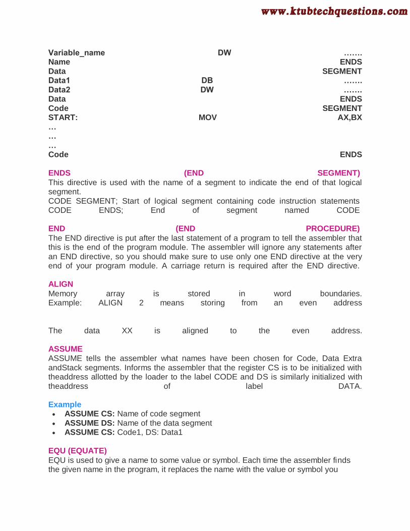
Variable_name DW ……. Name ENDS Data SEGMENT Data1 DB ……. Data2 DW ……. Data ENDS Code SEGMENT START: MOV AX,BX … … … Code ENDS
ENDS (END SEGMENT)
This directive is used with the name of a segment to indicate the end of that logical segment. CODE SEGMENT; Start of logical segment containing code instruction statements CODE ENDS; End of segment named CODE END (END PROCEDURE)
The END directive is put after the last statement of a program to tell the assembler that this is the end of the program module. The assembler will ignore any statements after an END directive, so you should make sure to use only one END directive at the very end of your program module. A carriage return is required after the END directive. ALIGN
Memory array is stored in word boundaries. Example: ALIGN 2 means storing from an even address The data XX is aligned to the even address. ASSUME ASSUME tells the assembler what names have been chosen for Code, Data Extra andStack segments. Informs the assembler that the register CS is to be initialized with theaddress allotted by the loader to the label CODE and DS is similarly initialized with theaddress of label DATA. Example ASSUME CS: Name of code segment ASSUME DS: Name of the data segment ASSUME CS: Code1, DS: Data1
EQU (EQUATE)
EQU is used to give a name to some value or symbol. Each time the assembler finds the given name in the program, it replaces the name with the value or symbol you

equated with that name. Example Data SEGMENT Num1 EQU 50H Num2 EQU 66H Data ENDS Numeric value 50H and 66H are assigned to Num1 and Num2 ORG (ORIGIN)
ORG Changes the starting offset address of the data in the data segment. As an assembler assembles a section of a data declarations or instruction statements, it uses a location counter to keep track of how many bytes it is from the start of a segment at any time. The location counter is automatically set to 0000 when assembler starts reading a segment. The ORG directive allows you to set the location counter to a desired value at any point in the program. Example:The statement ORG 2000H tells the assembler to set the location counter to
2000H. A “$” it often used to symbolically represent the current value of the location counter, the $ actually represents the next available byte location where the assembler can put a data or code byte. The $ is often used in ORG statements to tell the assembler to make some change in the location counter relative to its current value. The statement ORG $ + 100 tells the assembler increment the value of the location counter by 100 from its current value. PROC (PROCEDURE)
The PROC directive is used to identify the start of a procedure. The PROC directive follows a name you give the procedure. After the PROC directive, the term near or the term far is used to specify the type of the procedure. Example: DIVIDE PROC FAR
This identifies the start of a procedure named DIVIDE and tells the assembler that the procedure is far (in a segment with different name from the one that contains the instructions which calls the procedure). The PROC directive is used with the ENDP directive to “bracket” a procedure. NEAR: the procedure resides in the same code segment. (Local) FAR: resides at any location in the memory.
Example Add PROC NEAR
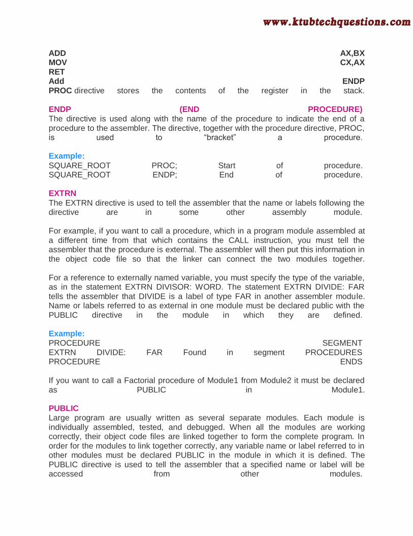
ADD AX,BX MOV CX,AX RET Add ENDP PROC directive stores the contents of the register in the stack. ENDP (END PROCEDURE) The directive is used along with the name of the procedure to indicate the end of a procedure to the assembler. The directive, together with the procedure directive, PROC, is used to “bracket” a procedure. Example:
SQUARE_ROOT PROC; Start of procedure. SQUARE_ROOT ENDP; End of procedure. EXTRN
The EXTRN directive is used to tell the assembler that the name or labels following the directive are in some other assembly module. For example, if you want to call a procedure, which in a program module assembled at a different time from that which contains the CALL instruction, you must tell the assembler that the procedure is external. The assembler will then put this information in the object code file so that the linker can connect the two modules together. For a reference to externally named variable, you must specify the type of the variable, as in the statement EXTRN DIVISOR: WORD. The statement EXTRN DIVIDE: FAR tells the assembler that DIVIDE is a label of type FAR in another assembler module. Name or labels referred to as external in one module must be declared public with the PUBLIC directive in the module in which they are defined. Example: PROCEDURE SEGMENT EXTRN DIVIDE: FAR Found in segment PROCEDURES PROCEDURE ENDS If you want to call a Factorial procedure of Module1 from Module2 it must be declared as PUBLIC in Module1. PUBLIC Large program are usually written as several separate modules. Each module is individually assembled, tested, and debugged. When all the modules are working correctly, their object code files are linked together to form the complete program. In order for the modules to link together correctly, any variable name or label referred to in other modules must be declared PUBLIC in the module in which it is defined. The PUBLIC directive is used to tell the assembler that a specified name or label will be accessed from other modules.
Example:
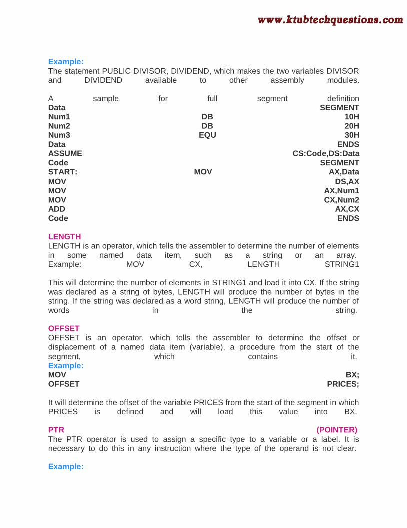
The statement PUBLIC DIVISOR, DIVIDEND, which makes the two variables DIVISOR and DIVIDEND available to other assembly modules. A sample for full segment definition Data SEGMENT Num1 DB 10H Num2 DB 20H Num3 EQU 30H Data ENDS ASSUME CS:Code,DS:Data Code SEGMENT START: MOV AX,Data MOV DS,AX MOV AX,Num1 MOV CX,Num2 ADD AX,CX Code ENDS LENGTH LENGTH is an operator, which tells the assembler to determine the number of elements in some named data item, such as a string or an array. Example: MOV CX, LENGTH STRING1 This will determine the number of elements in STRING1 and load it into CX. If the string was declared as a string of bytes, LENGTH will produce the number of bytes in the string. If the string was declared as a word string, LENGTH will produce the number of words in the string. OFFSET OFFSET is an operator, which tells the assembler to determine the offset or displacement of a named data item (variable), a procedure from the start of the segment, which contains it. Example: MOV BX; OFFSET PRICES; It will determine the offset of the variable PRICES from the start of the segment in which PRICES is defined and will load this value into BX. PTR (POINTER)
The PTR operator is used to assign a specific type to a variable or a label. It is necessary to do this in any instruction where the type of the operand is not clear. Example:

INC [BX] It will not know whether to increment the byte pointed to by BX. We use the PTR operator to clarify how we want the assembler to code the instruction.
INC BYTE PTR [BX]
This statement tells the assembler that we want to increment the byte pointed to by BX.
INC WORD PTR [BX] This statement tells the assembler that we want to increment the word pointed to by BX. The PTR operator assigns the type specified before PTR to the variable specified after PTR. We can also use the PTR operator to clarify our intentions when we use indirect Jump instructions. Example:
If we want to do a near jump, we write the instruction as JMP WORD PTR [BX]. If we want to do a far jump, we write the instruction as JMP DWORD PTR [BX]. EVEN (ALIGN ON EVEN MEMORY ADDRESS)
As an assembler assembles a section of data declaration or instruction statements, it uses a location counter to keep track of how many bytes it is from the start of a segment at any time. The EVEN directive tells the assembler to increment the location counter to the next even address, if it is not already at an even address. A NOP instruction will be inserted in the location incremented over. Example: DATA SEGMENT; SALES DB 9 DUP (?); Location counter will point to 0009 after this instruction. EVEN; Increment location counter to 000AH INVENTORY DW 100 DUP (0); Array of 100 words starting on even address for quicker read DATA ENDS; NAME The NAME directive is used to give a specific name to each assembly module when programs consisting of several modules are written. LABEL As an assembler assembles a section of a data declarations or instruction statements, it uses a location counter to be keep track of how many bytes it is from the start of a segment at any time. The LABEL directive is used to give a name to the current value in the location counter. The LABEL directive must be followed by a term that specifics the type you want to associate with that name. If the label is going to be used as the destination for a jump or

a call, then the label must be specified as type near or type far. If the label is going to be used to reference a data item, then the label must be specified as type byte, type word, or type double word. Here’s how we use the LABEL directive for a jump address. ENTRY_POINT LABEL FAR; Can jump to here from another segment NEXT: MOV AL, BL; Can not do a far jump directly to a label with a colon The following example shows how we use the label directive for a data reference. STACK_SEG SEGMENT STACK
DW 100 DUP (0); Set aside 100 words for stack STACK_TOP LABEL WORD; Give name to next location after last word in stack STACK_SEG ENDS To initialize stack pointer, use MOV SP OFFSET STACK_TOP SHORT
The SHORT operator is used to tell the assembler that only a 1 byte displacement is needed to code a jump instruction in the program. The destination must in the range of –128 bytes to +127 bytes from the address of the instruction after the jump. Example: JMP SHORT NEARBY_LABEL TYPE
The TYPE operator tells the assembler to determine the type of a specified variable. The assembler actually determines the number of bytes in the type of the variable. For a byte-type variable, the assembler will give a value of 1, for a word-type variable, the assembler will give a value of 2, and for a double word-type variable, it will give a value of 4. GLOBAL (DECLARE SYMBOLS AS PUBLIC OR EXTRN) The GLOBAL directive can be used in place of a PUBLIC directive or in place of an EXTRN directive. For a name or symbol defined in the current assembly module, the GLOBAL directive is used to make the symbol available to other modules. Example:
GLOBAL DIVISOR This statement makes the variable DIVISOR public so that it can be accessed from other assembly modules. INCLUDE (INCLUDE SOURCE CODE FROM FILE)
This directive is used to tell the assembler to insert a block of source code from the named file into the current source module.

OTHER DIRECTIVES:
There are several other directives that can be used for Conditional Assembly as listed below: IF If the expression is true IFB If the argument is blank IFNB If the argument is not blank IFDEF If the label has been defined IFNDEF If the label has not been defined IFIDN If argument 1 equals argument 2 IFDIF If argument 1 does not equal argument 2
With each of the above constructs, the code that follows gets assembled only if the stated condition is true. MACROS
Macros provide several powerful mechanisms useful for the development of generic programs. A Macro is a group of instructions with a name. When a macro is invoked, the associated set of instructions is inserted in place in to the source, replacing the macro name. This“macro expansion” is done by a Macro Preprocessor and it happens before assembly. Thus the actual Assembler sees the “expanded” source! We could consider the macro as shorthand for a piece of text; somewhat like a new pseudo code instruction. Macros and Procedures:
Macros are similar to procedures in some respects, yet are quite different in many other respects. Procedure:
Only one copy exists in memory. Thus memory consumed is less. “Called” when required;
Execution time overhead is present because of the call and return instructions. Macro: When a macro is “invoked”, the corresponding text is “inserted” in to the source.
Thus multiple copies exist in the memory leading to greater space requirements. However, there is no execution overhead because there are no additional call and
return instructions. The code is in-place. These concepts are illustrated in the following figure:
MACRO Definition:
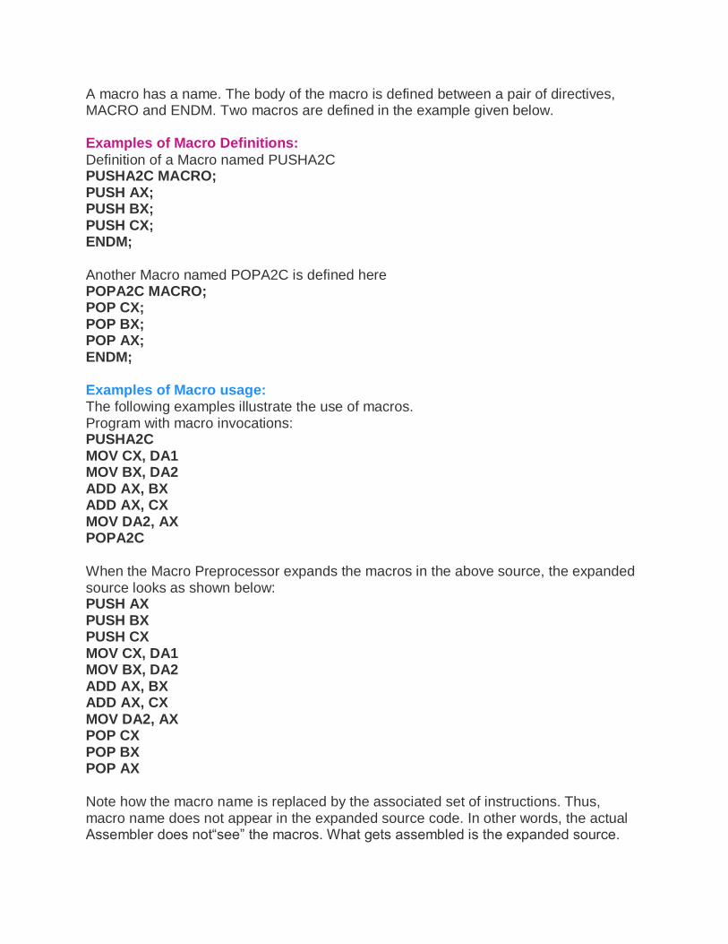
A macro has a name. The body of the macro is defined between a pair of directives, MACRO and ENDM. Two macros are defined in the example given below. Examples of Macro Definitions:
Definition of a Macro named PUSHA2C PUSHA2C MACRO; PUSH AX; PUSH BX; PUSH CX; ENDM;
Another Macro named POPA2C is defined here POPA2C MACRO; POP CX; POP BX; POP AX; ENDM; Examples of Macro usage: The following examples illustrate the use of macros. Program with macro invocations: PUSHA2C MOV CX, DA1 MOV BX, DA2 ADD AX, BX ADD AX, CX MOV DA2, AX POPA2C
When the Macro Preprocessor expands the macros in the above source, the expanded source looks as shown below: PUSH AX PUSH BX PUSH CX MOV CX, DA1 MOV BX, DA2 ADD AX, BX ADD AX, CX MOV DA2, AX POP CX POP BX POP AX
Note how the macro name is replaced by the associated set of instructions. Thus, macro name does not appear in the expanded source code. In other words, the actual Assembler does not“see” the macros. What gets assembled is the expanded source.
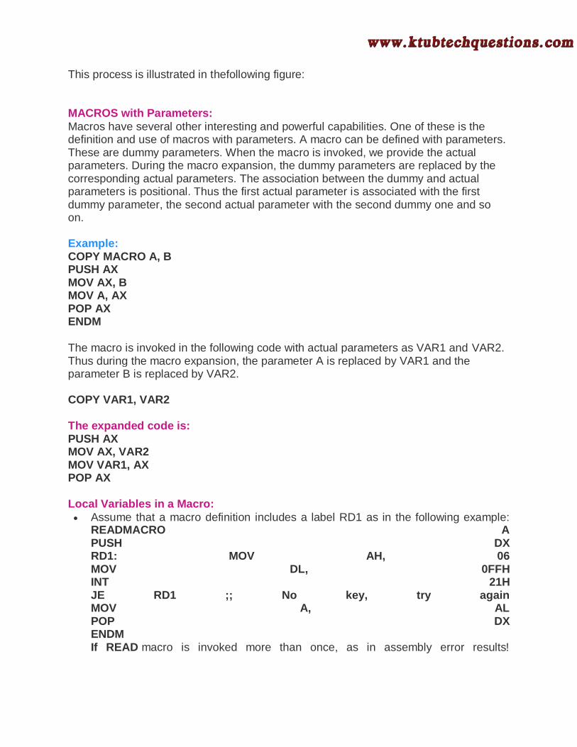
This process is illustrated in thefollowing figure: MACROS with Parameters:
Macros have several other interesting and powerful capabilities. One of these is the definition and use of macros with parameters. A macro can be defined with parameters. These are dummy parameters. When the macro is invoked, we provide the actual parameters. During the macro expansion, the dummy parameters are replaced by the corresponding actual parameters. The association between the dummy and actual parameters is positional. Thus the first actual parameter is associated with the first dummy parameter, the second actual parameter with the second dummy one and so on. Example: COPY MACRO A, B PUSH AX MOV AX, B MOV A, AX POP AX ENDM
The macro is invoked in the following code with actual parameters as VAR1 and VAR2. Thus during the macro expansion, the parameter A is replaced by VAR1 and the parameter B is replaced by VAR2. COPY VAR1, VAR2
The expanded code is: PUSH AX MOV AX, VAR2 MOV VAR1, AX POP AX Local Variables in a Macro:
Assume that a macro definition includes a label RD1 as in the following example: READMACRO A PUSH DX RD1: MOV AH, 06 MOV DL, 0FFH INT 21H JE RD1 ;; No key, try again MOV A, AL POP DX ENDM If READ macro is invoked more than once, as in assembly error results!

READVAR1 READ VAR2
The problem is that the label RD1 appears in the expansion of READ VAR1 as well as in the expansion of READ VAR2. Hence, the label RD1 appears in both the expansions. In other words, the Assembler sees the label RD1 at two different places and this results in the “Multiple Definition” error! SOLUTION: Define RD1 as a local variable in the macro. READMACRO A LOCAL RD1 PUSH DX RD1: MOV AH, 06 MOV DL, 0FFH INT 21H JE RD1 ;; No key, try again MOV A, AL POP DX ENDM
Now, in each invocation of READ, the label RD1 will be replaced, automatically, with a unique label of the form ??xxxx ; where xxxx is a unique number generated by Assembler. This eliminates the problem of multiple definitions in the expanded source.
With the use of local variable as illustrated above, READ VAR1gets expanded as: PUSH DX ??0000: MOV AH, 06 MOV DL, 0FFH INT 21H JE ??0000 ;; No key, try again MOV VAR1, AL POP DX
Subsequently, if we write READ VAR2it gets expanded as: PUSH DX ??0001: MOV AH, 06 MOV DL, 0FFH INT 21H JE ??0001 ;; No key, try again MOV VAR2, AL POP DX Note how each invocation of the READ macro gets expanded with a new and unique label,generated automatically by the Assembler, in place of the local variable RD1. Further, note that LOCAL directive must immediately follow the MACRO directive. Another feature to note is that Comments in Macros are preceded by ;; (two semicolons) , and not as usual by ; (a single semicolon).

File of Macros:
We can place all the required Macros in a file of its own and then include the file into the source. Example: Suppose the Macros are placed in D:\MYAPP\MYMAC.MAC
Advanced Features: Conditional Assembly REPEAT, WHILE, and FOR statements in MACROS
Conditional Assembly: A set of statements enclosed by IF and ENDIF are assembled if the condition
stated with IF is true; otherwise, the statements are not assembled; no code is generated.
This is an Assembly time feature; not run-time behavior! Allows development of generic programs. From such a generic program, we can
produce specific source programs for specific application contexts. Example: Assume that our generic program has the following statements: IF WIDT WIDE DB 72 ELSE WIDE DB 80 ENDIF
Now the assembly language program that is generated depends on the value of WIDT. Assume the block is preceded by WIDT EQU 1 Then the assembled code is:WIDE DB 72 REPEAT Statement:
This statement allows a block of code to be repeated the specified number of times. This avoids repetitive typing and is much more elegant than Editor-level Copy-and-Paste operation. Example: REPEAT 3 INT 21H INC DL ENDM The generated code would be 3 repetitions of the block of 2 statements enclosed within REPEAT and ENDM as shown below: INT 21H INC DL INT 21H INC DL
INT 21H INC DL
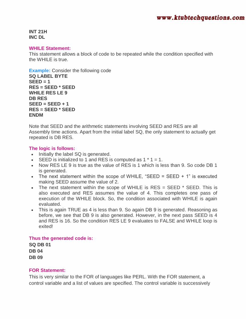
WHILE Statement:
This statement allows a block of code to be repeated while the condition specified with the WHILE is true. Example: Consider the following code SQ LABEL BYTE SEED = 1 RES = SEED * SEED WHILE RES LE 9 DB RES SEED = SEED + 1 RES = SEED * SEED ENDM
Note that SEED and the arithmetic statements involving SEED and RES are all Assembly time actions. Apart from the initial label SQ, the only statement to actually get repeated is DB RES. The logic is follows:
Initially the label SQ is generated. SEED is initialized to 1 and RES is computed as 1 * 1 = 1. Now RES LE 9 is true as the value of RES is 1 which is less than 9. So code DB 1
is generated. The next statement within the scope of WHILE, “SEED = SEED + 1” is executed
making SEED assume the value of 2. The next statement within the scope of WHILE is RES = SEED * SEED. This is
also executed and RES assumes the value of 4. This completes one pass of execution of the WHILE block. So, the condition associated with WHILE is again evaluated.
This is again TRUE as 4 is less than 9. So again DB 9 is generated. Reasoning as before, we see that DB 9 is also generated. However, in the next pass SEED is 4 and RES is 16. So the condition RES LE 9 evaluates to FALSE and WHILE loop is exited!
Thus the generated code is:
SQ DB 01
DB 04
DB 09
FOR Statement:
This is very similar to the FOR of languages like PERL. With the FOR statement, a
control variable and a list of values are specified. The control variable is successively

assigned values from the specified list and for each such value, the following block of
statements is repeated.
Example:
DISP MACRO CHR: VARARG
MOV AH, 2
FOR ARG,
MOV DL, ARG
INT 21H
ENDM
The outer Macro has one parameter which is specified as sequence of characters of
variable length. The inner FOR statement has two enclosed statements which will be
repeated for each value in the list . Thus in the following illustration, DISP is invoked
with 3 characters as parameters. The two statements within FOR scope are thus
repeated 3 times with ARG successively assuming the 3 characters.
Thus, the statement
DISP „V?,?T?,?U?gets expanded as
MOV AH, 2
MOV DL,?V?
INT 21H
MOV DL, ?T?
INT 21H
MOV DL, ?U?
INT 21H